

Fujitsu ETERNUS DX100 S4, ETERNUS DX200 S4, ETERNUS DX60 S3, ETERNUS DX100 S3, ETERNUS DX500 S3 Configuration Manual
...Page 1

P3AM-8012-10ENZ0
FUJITSU Storage
ETERNUS DX, ETERNUS AF
Configuration Guide (Power Synchronized Unit)
ETERNUS DX S4/S3 series Hybrid Storage Systems,
ETERNUS DX60 S2/DX80 S2/DX90 S2 Disk Storage Systems,
ETERNUS AF series, ETERNUS DX200F All-Flash Arrays
Page 2

This page is intentionally left blank.
Page 3

Preface
Fujitsu would like to thank you for purchasing our power synchronized unit for the ETERNUS DX/AF storage
systems.
The power synchronized unit is a device that synchronizes power operations of the ETERNUS DX/AF storage
systems with servers.
This manual introduces the user to the power synchronized unit, and explains the regular checks and
maintenance that are required.
Please carefully review the information outlined in this manual.
This manual is designed for use with the following ETERNUS DX/AF storage systems:
• ETERNUS DX60 S4/DX100 S4/DX200 S4 Hybrid Storage Systems
• ETERNUS DX500 S4/DX600 S4 Hybrid Storage Systems
• ETERNUS DX60 S3/DX100 S3/DX200 S3 Hybrid Storage Systems
• ETERNUS DX500 S3/DX600 S3 Hybrid Storage Systems
• ETERNUS DX8100 S3/DX8700 S3/DX8900 S3 Hybrid Storage Systems
• ETERNUS DX60 S2/DX80 S2/DX90 S2 Disk Storage Systems
• ETERNUS AF250 S2 All-Flash Arrays
• ETERNUS AF650 S2 All-Flash Arrays
• ETERNUS AF250 All-Flash Arrays
• ETERNUS AF650 All-Flash Arrays
• ETERNUS DX200F All-Flash Arrays
Applicable Environment
The power synchronized unit was designed and manufactured with user safety for general office
environments in mind. When using the power synchronized unit, follow the handling instructions, placement
and cautionary notes listed in this manual. If used beyond the limits described, the users may be at risk of
personal injury and/or material damage.
Using this Manual
This manual contains important information regarding safe usage.
Please read this manual carefully before using the power synchronized unit. Pay special attention to
"
Safety Precautions" (page 9), and understand the contents thoroughly before using the power synchronized
unit. Keep this manual in a safe place for future reference.
Fujitsu pays careful attention to the safe use of its products to prevent user injury and/or material damage. To
use the power synchronized unit properly, please follow the instructions in this manual.
Tenth Edition
October 2017
3
FUJITSU Storage ETERNUS DX, ETERNUS AF Configuration Guide (Power Synchronized Unit)
Copyright 2017 FUJITSU LIMITED P3AM-8012-10ENZ0
Page 4

Preface
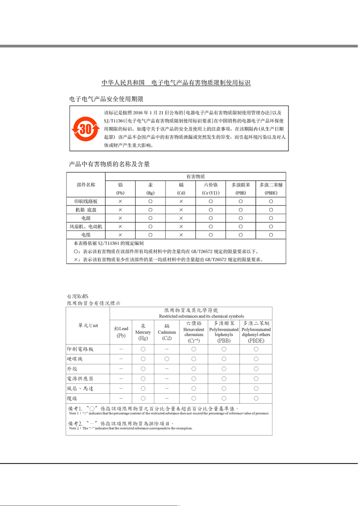
Compliance with Standards
The power synchronized unit is compliant with the following standards.
Type Standard
Product safety UL60950-1, CSA-C22.2 No. 60950-1, EN60950-1, IEC60950-1
Electromagnetic Compatibility FCC CFR47 part 15 Class A, ICES-003 Class A, EN55022 Class A, VCCI Class A
Electromagnetic Immunity EN55024
CE certification
Environmental compliance
The power synchronized unit is designed, developed and manufactured as contemplated for general use,
including without limitation, general office use, personal use, household use, and ordinary industrial use,
but is not designed, developed and manufactured for use in situations with accompanying fatal risks or
dangers that, unless extremely high safety is secured, could lead directly to death, personal injury, severe
physical damage or other loss (hereinafter "High Safety Required Use"), including without limitation,
nuclear reaction control in nuclear facility, aircraft flight control, air traffic control, mass transport control,
medical life support system, and missile launch control in weapon systems. Do not use the power
synchronized unit for High Safety Required Use without securing the sufficient safety level required. If you
wish to use the power synchronized unit for High Safety Required Use, please consult with our sales
representative before such use.
Electromagnetic Compatibility Directive 2004/108/EC
Low Voltage Directive 2006/95/EC
RoHS-compliant (Restriction of hazardous substances)
WEEE-compliant (Waste electrical and electronic equipment)
The company names, product names and service names mentioned in this document are registered
trademarks or trademarks of their respective companies.
Microsoft product screen shot(s) reprinted with permission from Microsoft Corporation.
4
FUJITSU Storage ETERNUS DX, ETERNUS AF Configuration Guide (Power Synchronized Unit)
Copyright 2017 FUJITSU LIMITED P3AM-8012-10ENZ0
Page 5
Preface
● Traditional Chinese
● Simplified Chinese
5
FUJITSU Storage ETERNUS DX, ETERNUS AF Configuration Guide (Power Synchronized Unit)
Copyright 2017 FUJITSU LIMITED P3AM-8012-10ENZ0
Page 6

Organization
This manual is composed of the following six chapters:
● Chapter 1 Overview
This chapter provides overviews, features, specifications, and system configuration examples of the power
synchronized unit. The names and usage of the various components for the power synchronized unit are
also described.
● Chapter 2 Installation
This chapter describes how to install the power synchronized unit.
● Chapter 3 Powering On and Off
This chapter describes how to turn on and off the power synchronized unit.
About this Manual
● Chapter 4 Connection and Settings
This chapter describes the connection and setup procedures to operate the power synchronized unit.
● Chapter 5 Adding a Connecting Device
This chapter describes how to connect the power synchronized unit when a device is added.
● Chapter 6 Operation and Maintenance
This chapter describes how to change the configuration and appropriate responses for any problems that
may occur.
Read this chapter when operating or performing maintenance on the power synchronized unit, or if an
error occurs.
Refer to the manuals for each peripheral concerning details not included in this manual.
6
FUJITSU Storage ETERNUS DX, ETERNUS AF Configuration Guide (Power Synchronized Unit)
Copyright 2017 FUJITSU LIMITED P3AM-8012-10ENZ0
Page 7
About this Manual
WARNING
CAUTION
Electric Shock
No Disassembly
Unplug
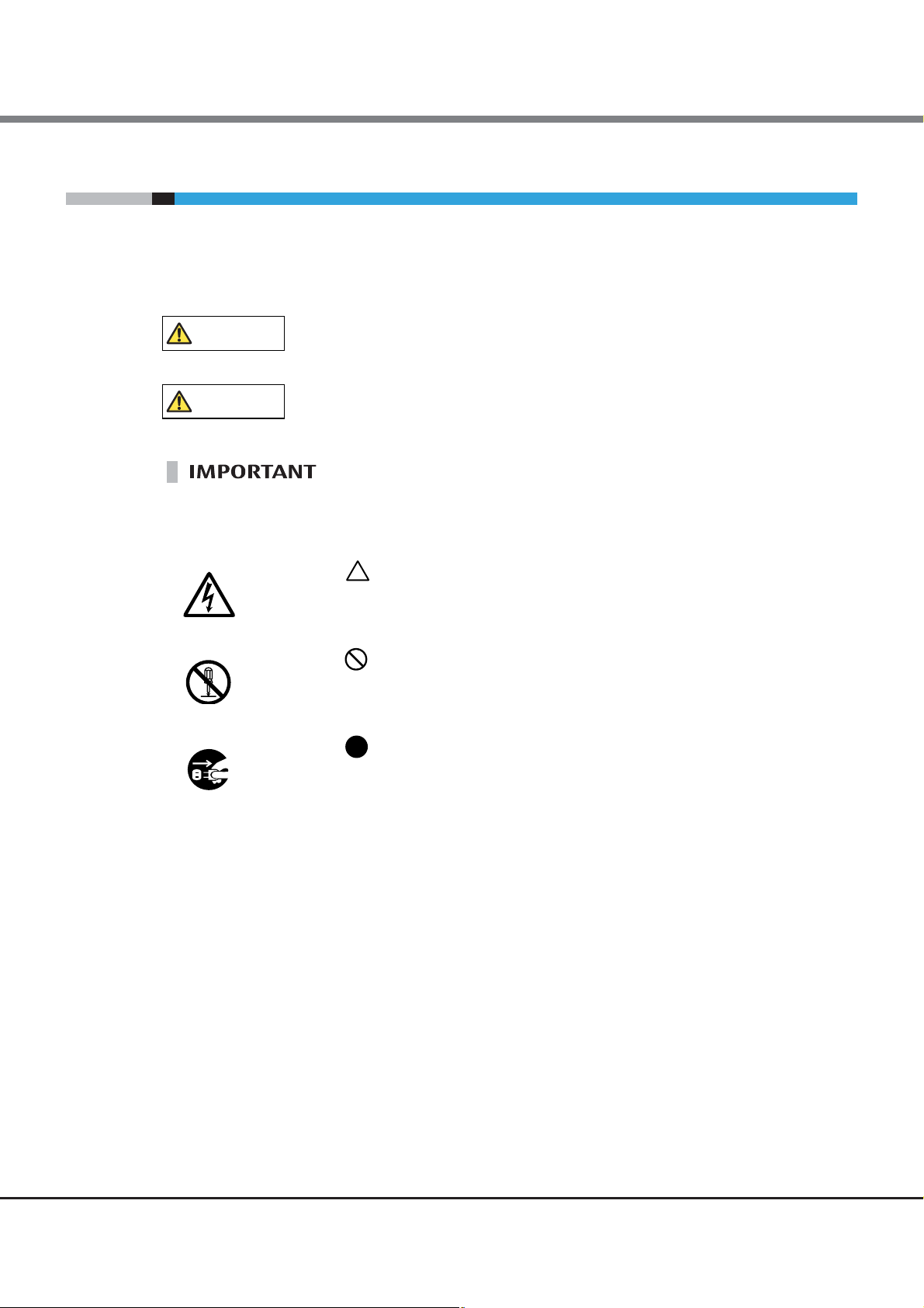
Warning Notations
Warning signs are shown throughout this manual in order to prevent injury to the user and/or material
damage. These signs are composed of a symbol and a message describing the recommended level of caution.
The following section explains the symbols, their levels of caution, and their meanings as used in this manual.
This symbol indicates the possibility of serious or fatal injury if the power
synchronized unit is not used properly.
This symbol indicates the possibility of minor or moderate personal injury, as
well as damage to the power synchronized unit and/or to other users and their
property, if the power synchronized unit is not used properly.
This symbol indicates IMPORTANT information for the user to note when using
the power synchronized unit.
The following symbols are used to indicate the type of warnings or cautions being described.
The triangle emphasizes the urgency of the WARNING and CAUTION
contents. Inside the triangle and above it are details concerning the symbol
(e.g. Electric Shock).
The barred "Do Not..." circle warns against certain actions.
The action which should be avoided is both illustrated inside the barred circle
and written above it (e.g. No Disassembly).
The black "Must Do..." circle indicates actions that must be taken.
The required action is both illustrated inside the black circle and written above
it (e.g. Unplug).
7
FUJITSU Storage ETERNUS DX, ETERNUS AF Configuration Guide (Power Synchronized Unit)
Copyright 2017 FUJITSU LIMITED P3AM-8012-10ENZ0
Page 8
About this Manual
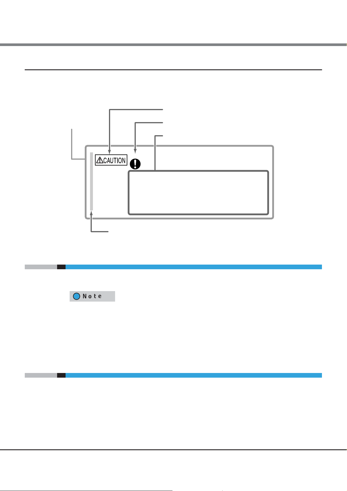
Warning Level Indicator
Warning Type Indicator
Warning Details
•
To avoid damaging the power synchronized unit, pay
attention to the following points when cleaning the power synchronized
unit.
Make sure to disconnect the power when cleaning.Be careful that no liquid seeps into the power synchronized unit
when using cleaners, etc.
-
Do not use alcohol or other solvents thinners to clean the
power synchronized unit.
-
Warning Layout Ribbon
Example Warning
Do
How Warnings are Presented in this Manual
A message is written beside the symbol indicating the caution level. This message is marked with a vertical
ribbon in the left margin, to distinguish this warning from ordinary descriptions.
An example is shown here.
Symbols Used in this Manual
About the Latest Version of this Manual and Contact Details
• The following symbol is used throughout this manual:
Functions and know how which can be useful when setting up or operating the
power synchronized unit.
• "ETERNUS DX/AF" refers to the ETERNUS DX60 S4/DX100 S4/DX200 S4, ETERNUS DX500 S4/DX600 S4,
ETERNUS DX60 S3/DX100 S3/DX200 S3, ETERNUS DX500 S3/DX600 S3, and ETERNUS DX8100 S3/DX8700 S3/
DX8900 S3 Hybrid Storage Systems; the ETERNUS DX60 S2/DX80 S2/DX90 S2 Disk Storage Systems; and
the ETERNUS AF250 S2/AF650 S2, ETERNUS AF250/AF650 and ETERNUS DX200F All-Flash Arrays in this
manual.
The information in this manual is subject to change without notice for improvement and functionality
expansion of the power synchronized unit.
The latest version of this manual and important service and support contacts (see "Contact Fujitsu") for Fujitsu
Customer Service in your country of purchase is available at the following website:
http://www.fujitsu.com/global/support/products/computing/storage/disk/manuals/manual.html
FUJITSU Storage ETERNUS DX, ETERNUS AF Configuration Guide (Power Synchronized Unit)
Copyright 2017 FUJITSU LIMITED P3AM-8012-10ENZ0
8
Page 9
Safety Precautions
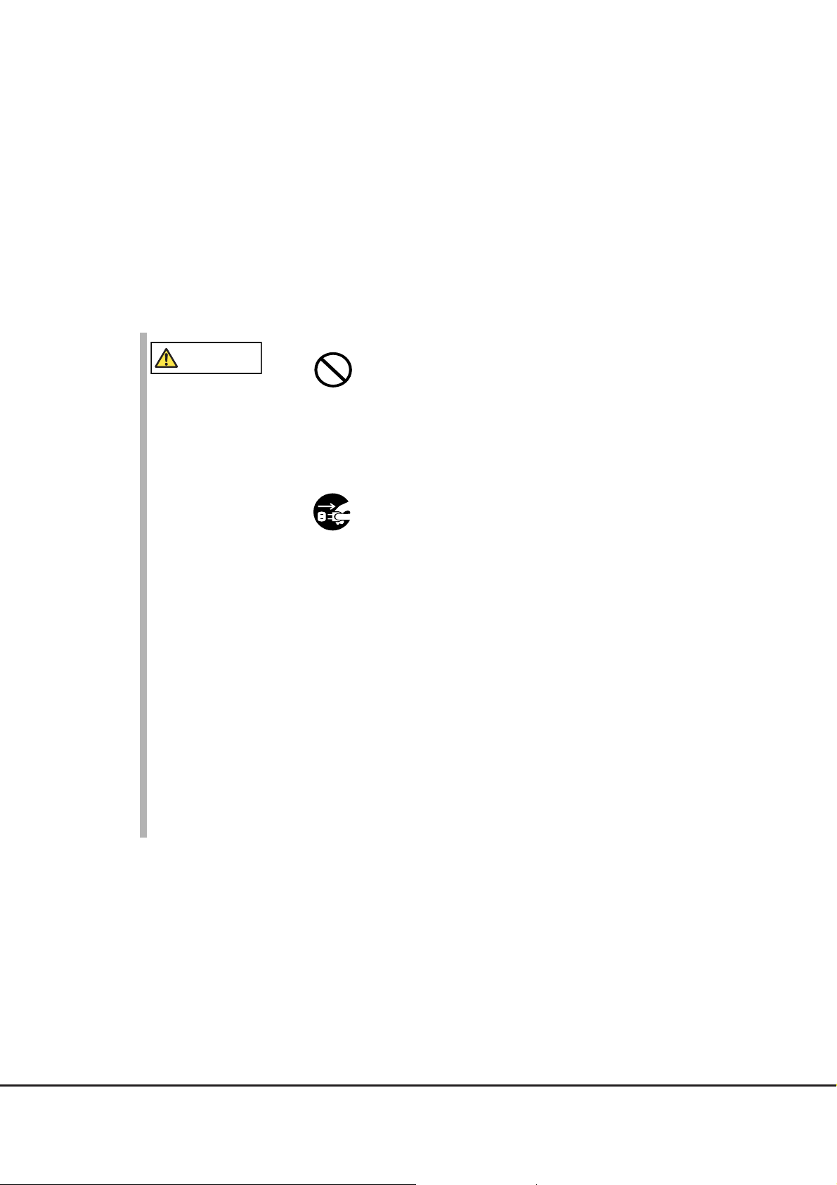
WARNING
Do Not
Unplug
This section describes safety precautions.
Make sure to follow the instructions described below to ensure the safe use of the power synchronized unit.
■ If you detect an unusual occurrence during operation
• If the power cord and/or power plug is damaged, do not use the power
synchronized unit and contact your sales representative or your maintenance
engineer. Never attempt to repair the power synchronized unit by yourself. Not
doing so may cause electric shock or fire.
• If the power synchronized unit overheats, gives off smoke or an unusual odor,
makes an unusual sound, or shakes abnormally, immediately disconnect the
power plug from the socket. After the problem has subsided, contact your
sales representative or your maintenance engineer. Never attempt to repair
the power synchronized unit by yourself. Not doing so may cause electric
shock or fire.
• If any liquids such as water or foreign objects like metal fragments get into the
power synchronized unit, immediately disconnect the power plug from the
socket. Then, contact your sales representative or your maintenance engineer.
Do not attempt to repair the power synchronized unit by yourself. Doing so
may cause electric shock or fire.
• If the power synchronized unit is dropped or covers are damaged, immediately
disconnect the power plug from the socket. Then, contact your sales
representative or your maintenance engineer. Do not attempt to repair the
power synchronized unit by yourself. Doing so may cause electric shock or fire.
9
FUJITSU Storage ETERNUS DX, ETERNUS AF Configuration Guide (Power Synchronized Unit)
Copyright 2017 FUJITSU LIMITED P3AM-8012-10ENZ0
Page 10
Safety Precautions
WARNING
Do Not
Unplug
CAUTION
Do Not
■ Instructions for installation
• Do not place the power synchronized unit in an area with bad ventilation or
where anything that may cause a fire, or flammable gases are generated.
Doing so may cause a fire and damage the power synchronized unit.
• Do not place the power synchronized unit in locations subject to oil smoke,
steam, humidity and dust, or in places where the power synchronized unit
may come into contact with water. Doing so may lead to electric shock, fire,
and/or damage the power synchronized unit.
• Do not place any objects containing water such as vases and cups on or near
the power synchronized unit. Doing so may cause water to get into the power
synchronized unit and lead to electric shock, fire, and/or damage the power
synchronized unit.
• Do not place the power synchronized unit on an unstable floor. Doing so may
cause the power synchronized unit to fall, resulting in injury or damage to the
power synchronized unit.
• Do not connect power cords or any other cables to the power synchronized unit
during thunderstorms. Doing so may lead to electric shock and/or fire.
• When the power synchronized unit is installed or moved, disconnect the power
plug from the socket. Remove all the connected cables. Watch your step during
the operation. Not doing so may damage the power cords and cause electric
shock or fire. Failure to do so may also cause the power synchronized unit to
fall and injure others.
• Do not use the power synchronized unit in an area affected by corrosive gas or
in a salty environment. Doing so may cause device failure.
• Do not knock or place heavy objects on the power synchronized unit or
optional products. Doing so may cause injury or damage the power
synchronized unit.
10
FUJITSU Storage ETERNUS DX, ETERNUS AF Configuration Guide (Power Synchronized Unit)
Copyright 2017 FUJITSU LIMITED P3AM-8012-10ENZ0
Page 11
Safety Precautions
CAUTION
Do Not
Do
WARNING
No Disassembly
Do Not
• Do not place the power synchronized unit in areas with strong magnetic fields,
such as in the vicinity of TVs or speakers. Doing so may damage the power
synchronized unit and cause the power synchronized unit to malfunction.
• Do not place power cords and other cables in locations where they may
become trip hazards. Doing so may cause injury or damage the power
synchronized unit .
• Do not place the power synchronized unit on a slanted or unstable surface or
in areas that tend to shake. Doing so may cause it to tip over and injure
others. Also, do not place the power synchronized unit in high traffic areas
such as in a hallway. Passersby can shake the unit, damage it or cause malfunction.
• Place the power synchronized unit in an environment in which the
temperature and humidity satisfy the environmental conditions described in
"1.3
Specifications" (page 23).
- For 24-hour operation, ensure that the schedule for air conditioning is able
to maintain the required temperature. Failure to do so may result in
damage to the device.
- During the winter, control the heating system to limit ambient
temperature rises to less than 15C per hour to prevent condensation.
Failure to do so could lead to electric shock and damage the power
synchronized unit.
■ Handling the power synchronized unit
• Do not attempt to repair, disassemble, or remodel the power synchronized
unit by yourself. Doing so may cause electric shock or fire.
• Do not use a voltage other than that indicated. Doing so may cause electric
shock or fire.
11
FUJITSU Storage ETERNUS DX, ETERNUS AF Configuration Guide (Power Synchronized Unit)
Copyright 2017 FUJITSU LIMITED P3AM-8012-10ENZ0
Page 12
Safety Precautions
WARNING
Do Not
Do
• Do not handle the power plug with wet hands. Doing so may cause electric
shock.
• Do not wind power cords too tightly at the root of the power cord. Doing so
stresses the cords and may expose or snap the inner wires, which can lead to
electric shock or fire.
• Do not damage or modify the power cord or the power plug. Heating, forced
bending, twisting, pulling, or placing heavy objects on the power cord or the
power plug will damage it, causing electric shock or fire.
• Do not plug all the power cords into a single outlet. Doing so may cause
electric shock or fire.
• Do not use a power cord that does not satisfy the specifications of the power
synchronized unit and the AC sensor unit. Doing so may cause electric shock,
fire, or device failure.
• Do not use any products other than the optional products for the power
synchronized unit. Doing so may cause electric shock, fire, or device failure.
• Do not insert or drop foreign objects such as metals or flammable objects into
openings in the power synchronized unit such as air vents. Doing so may
cause electric shock, fire, or device failure.
• Do not obstruct the openings in the power synchronized unit such as air vents.
Doing so may cause overheating that leads to fire and device failure.
• Do not use any flammable type cleaning sprays. Doing so may cause fire or
device failure.
• Use only power sockets that have a ground. Failure to do so may cause electric
shock, fire, or malfunction.
• Disconnect the power plug from the socket during thunderstorms. Failure to
do so may lead to electric shock, fire, or device failure.
• Ensure the power plug is fully inserted into the socket. Failure to do so may
cause electric shock or fire.
12
FUJITSU Storage ETERNUS DX, ETERNUS AF Configuration Guide (Power Synchronized Unit)
Copyright 2017 FUJITSU LIMITED P3AM-8012-10ENZ0
Page 13
Safety Precautions
WARNING
Do
Do Not Wet
Unplug
CAUTION
Do Not
Do
• Install optional products for the power synchronized unit by following the
instructions described in this manual. If an optional product is installed in any
other way, device failure or electric shock may occur.
• Do not pour or spill water on the power synchronized unit. Doing so may cause
electric shock, fire, or device failure.
• When unplugging the power plug, do not pull on the cable, hold the plug.
Pulling the cable may expose or snap the inner wires, which can lead to
electric shock or fire.
• Use a dry cloth to remove all dust from plugs and sockets. Not doing so may
cause electric shock or fire.
• When the power synchronized unit is not used for a long period of time,
unplug all power plugs. Failure to do so may lead to fire.
• When the power synchronized unit is pulled out from the rack, make sure not
to hit your head if you are operating devices under the power synchronized
unit. Not doing so may cause injury.
• Do not put your finger into the inlet/outlet. Doing so may cause injury or
device failure.
• Do not remove the cover from the power synchronized unit inlet/outlet unless
necessary. Doing so may cause device failure.
• Do not use devices such as mobile phones that emit radiation in the vicinity of
the power synchronized unit. Doing so may cause malfunction.
• Before applying insecticides for pest control, turn off the power synchronized
unit and cover it with a plastic sheet. Not doing so may damage the power
synchronized unit.
13
FUJITSU Storage ETERNUS DX, ETERNUS AF Configuration Guide (Power Synchronized Unit)
Copyright 2017 FUJITSU LIMITED P3AM-8012-10ENZ0
Page 14
Safety Precautions
CAUTION
Do
CAUTION
Do
■ Instructions for rack installation
• Note the following points when cleaning the power synchronized unit. Failure
to do so may cause device failure.
- Make sure the power synchronized unit is turned off.
- Do not allow liquids such as cleaner to get into the power synchronized
unit.
- Never use organic solvents such as alcohol or thinner to clean the power
synchronized unit.
• Especially for an enclosed rack with doors, or when multiple devices are to be
mounted and running, it is important to realize that the temperature inside
the cabinet will be considerably higher than that of the room. Make sure the
rack internal ambient temperatures do not exceed the environmental
conditions for temperature described in "1.3
to do so may damage the power synchronized unit.
• When installing the power synchronized unit with other devices into the same
rack, the airflow of the device installed on and under the power synchronized
unit may interfere with each other and reduce the effect of device cooling.
Make sure to leave plenty of room between the devices if required. Failure to
do so may damage the power synchronized unit and lead to malfunction.
• When installing the power synchronized unit in a rack, be careful not to pinch
your fingers in the rack. Doing so may cause injury.
• Install the blank panels provided with the rack where no other devices are
installed. Failure to do so may cause the power synchronized unit to overheat,
resulting in damage to the device.
• When moving the rack after installing the power synchronized unit, make sure
to contact your sales representative or your maintenance engineer. Do not
move the rack by yourself. Doing so may cause injury and/or damage the
power synchronized unit.
Specifications" (page 23). Failure
14
FUJITSU Storage ETERNUS DX, ETERNUS AF Configuration Guide (Power Synchronized Unit)
Copyright 2017 FUJITSU LIMITED P3AM-8012-10ENZ0
Page 15

Safety Precautions
CAUTION
Do Not
Do
90
Do not bend
more than 90 degrees
Do not fold
■ Handling cables
• Do not damage or modify the cables such as heating, forced bending,
twisting, pulling, or placing heavy objects on them. Doing so may damage the
cables and cause the power synchronized unit to malfunction.
• Do not forcibly bend or fold the cable. Doing so may damage the cable and
cause the power synchronized unit to malfunction.
• Firmly insert cable connectors into inlets, outlets, or sockets. Failure to do so
may cause the power synchronized unit to malfunction.
• When inserting or removing the cable, only hold the connector. Do not hold
the cable. Doing so may damage the cable and cause the power synchronized
unit to malfunction.
• Remove any dirt, dust, oil, grease, etc on cable connectors. Failure to do so
may cause the power synchronized unit to malfunction.
15
FUJITSU Storage ETERNUS DX, ETERNUS AF Configuration Guide (Power Synchronized Unit)
Copyright 2017 FUJITSU LIMITED P3AM-8012-10ENZ0
Page 16
Labels
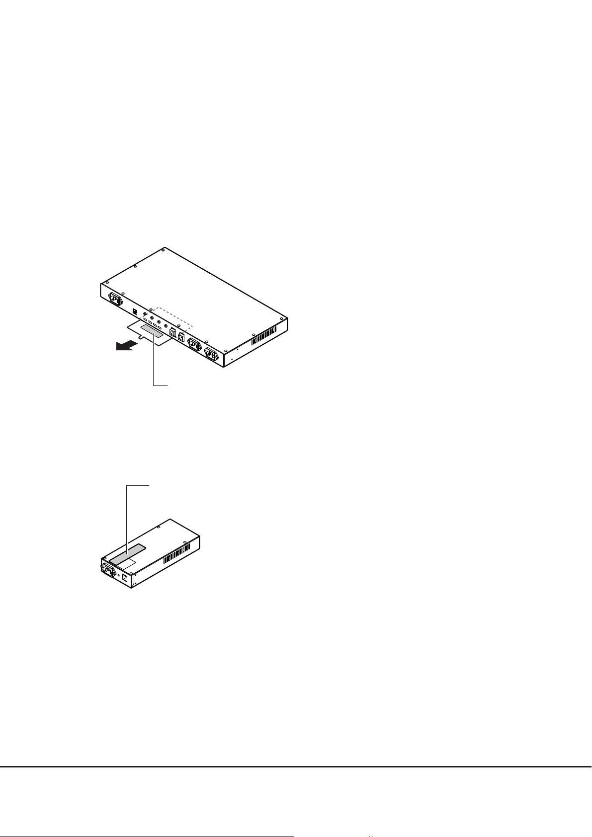
Manufacturer’s label
Indicates the model, serial number, etc.
This label is attached to the plate in the label holder
on the bottom of the power synchronized unit.
It can be checked by pulling out the plate
when the power synchronized unit is installed in a rack.
Manufacturer’s label
Indicates the model, serial number, etc.
Warning labels and manufacturer's labels are found in various places of the power synchronized unit, as
shown in the example below.
Never remove these labels from the equipment or allow them to become dirty.
■ Power synchronized unit
■ AC sensor unit
FUJITSU Storage ETERNUS DX, ETERNUS AF Configuration Guide (Power Synchronized Unit)
16
Copyright 2017 FUJITSU LIMITED P3AM-8012-10ENZ0
Page 17

Table of Contents
Chapter 1 Overview 21
1.1 External View .................................................................................................................... 21
1.2 Features ............................................................................................................................ 22
1.3 Specifications .................................................................................................................... 23
1.4 Components ...................................................................................................................... 24
1.4.1 Power Synchronized Unit ...............................................................................................................................24
1.4.2 AC Sensor Unit (Optional) .............................................................................................................................. 26
1.5 System Configuration ........................................................................................................27
1.6 Power Management for Power Synchronization ................................................................ 29
Chapter 2 Installation 33
2.1 Package Contents Check ................................................................................................... 33
2.2 Preparation ....................................................................................................................... 34
2.2.1 Installation Area ............................................................................................................................................ 34
2.2.2 Checking Power Sockets and Server UPS Unit Outlets .................................................................................... 34
2.2.3 Preparing Power Cords ...................................................................................................................................34
2.3 Installing in a Rack ........................................................................................................... 35
2.3.1 Installing a Power Synchronized Unit ............................................................................................................ 36
2.3.2 Installing an AC Sensor Unit ........................................................................................................................... 39
Chapter 3 Powering On and Off 43
Chapter 4 Connection and Settings 44
4.1 Setting the ETERNUS DX/AF ............................................................................................... 45
4.2 Turning on the Power Synchronized Unit .......................................................................... 50
4.3 Connecting Cascade Cables ............................................................................................... 53
4.4 Connecting to the Server UPS Unit ....................................................................................56
4.4.1 Connecting the Server UPS Unit to the Power Synchronized Unit ................................................................... 57
4.4.2 Connecting the AC Sensor Unit ...................................................................................................................... 58
4.5 Connecting to the ETERNUS DX/AF .................................................................................... 61
17
FUJITSU Storage ETERNUS DX, ETERNUS AF Configuration Guide (Power Synchronized Unit)
Copyright 2017 FUJITSU LIMITED P3AM-8012-10ENZ0
Page 18

Table of Contents
4.6 Checking after Connection ................................................................................................64
Chapter 5 Adding a Connecting Device 65
5.1 Connection Procedure When Adding a Server ................................................................... 65
5.2 Connection Procedure When Adding an ETERNUS DX/AF ................................................... 67
Chapter 6 Operation and Maintenance 71
6.1 Checking the Power Synchronized Unit Status .................................................................. 71
6.2 Device Replacement After Operation Startup .................................................................... 71
6.2.1 Replacing a Server .........................................................................................................................................71
6.2.2 Replacing a Power Synchronized Unit ............................................................................................................ 72
6.2.3 Replacing an AC Sensor Unit .......................................................................................................................... 72
6.3 Troubleshooting ................................................................................................................ 73
6.3.1 Check List ...................................................................................................................................................... 73
6.3.2 Trouble Record ............................................................................................................................................... 76
18
FUJITSU Storage ETERNUS DX, ETERNUS AF Configuration Guide (Power Synchronized Unit)
Copyright 2017 FUJITSU LIMITED P3AM-8012-10ENZ0
Page 19

List of Figures
Figure 1.1 External view of a power synchronized unit ................................................................................................ 21
Figure 1.2 External view of an AC sensor unit .............................................................................................................. 21
Figure 1.3 Components (power synchronized unit)...................................................................................................... 24
Figure 1.4 Components (AC sensor unit) ...................................................................................................................... 26
Figure 1.5 System configuration example (power synchronization with two server UPS units) .................................... 27
Figure 1.6 System configuration example (power synchronization with three or more server UPS units) .................... 28
Figure 1.7 Power on using a power synchronized unit ................................................................................................. 29
Figure 1.8 Operation timing chart when using a power synchronized unit (powering on) ........................................... 30
Figure 1.9 Power off using a power synchronized unit ................................................................................................. 31
Figure 1.10 Operation timing chart when using a power synchronized unit (powering off) ........................................... 32
Figure 4.1 ETERNUS DX60 S4/DX100 S4/DX200 S4, ETERNUS DX500 S4/DX600 S4,
ETERNUS DX60 S3/DX100 S3/DX200 S3, ETERNUS DX500 S3/DX600 S3,
ETERNUS DX8100 S3, ETERNUS AF250 S2/AF650 S2, ETERNUS AF250/AF650, and
ETERNUS DX200F setup (Setup Power Management screen)....................................................................... 45
Figure 4.2 ETERNUS DX8700 S3/DX8900 S3 setup (Setup Power Management screen)................................................ 47
Figure 4.3 ETERNUS DX80 S2/DX90 S2 setup (Setup Power Management screen)........................................................ 48
Figure 4.4 ETERNUS DX60 S2 setup (Setup Power Management screen)...................................................................... 49
Figure 4.5 Cascade cable connection............................................................................................................................ 53
Figure 4.6 Connection for the server UPS units and the AC sensor units....................................................................... 56
Figure 6.1 Trouble record ............................................................................................................................................. 76
19
FUJITSU Storage ETERNUS DX, ETERNUS AF Configuration Guide (Power Synchronized Unit)
Copyright 2017 FUJITSU LIMITED P3AM-8012-10ENZ0
Page 20

List of Tables
Table 1.1 Specifications .............................................................................................................................................. 23
Table 1.2 Status and meanings of each LED (for power synchronized units) .............................................................. 25
Table 1.3 Status and meanings of each LED (for AC sensor units)............................................................................... 26
Table 2.1 List of package contents (power synchronized unit).................................................................................... 33
Table 2.2 List of package contents (AC sensor unit).................................................................................................... 33
20
FUJITSU Storage ETERNUS DX, ETERNUS AF Configuration Guide (Power Synchronized Unit)
Copyright 2017 FUJITSU LIMITED P3AM-8012-10ENZ0
Page 21
Chapter 1
Overview
This chapter provides external views, features, specifications, and system configuration examples of the
power synchronized unit and the AC sensor unit (optional). The names and usages of the various components
of the power synchronized unit and the AC sensor unit are also described.
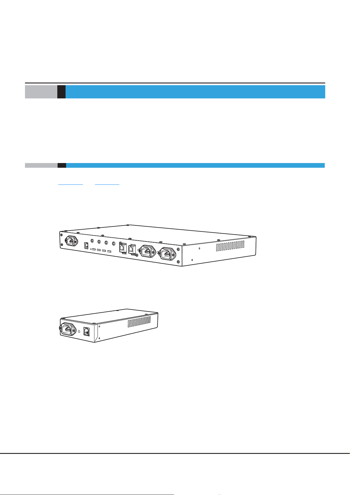
1.1 External View
Figure 1.1 and Figure 1.2 show the external views of the power synchronized unit and the AC sensor unit.
■ Power synchronized unit
Figure 1.1 External view of a power synchronized unit
■ AC sensor unit
Figure 1.2 External view of an AC sensor unit
21
FUJITSU Storage ETERNUS DX, ETERNUS AF Configuration Guide (Power Synchronized Unit)
Copyright 2017 FUJITSU LIMITED P3AM-8012-10ENZ0
Page 22

Chapter 1 Overview
1.2 Features
1.2 Features
This section explains the features of the power synchronized unit and the AC sensor unit.
• Powering the ETERNUS DX/AF on and off can be synchronized with a server by connecting to the
Uninterruptible Power Supply (UPS) unit to which the server is connected.
As well as the UPS unit to which the server is connected (referred to as "server UPS unit" in the remainder of
this manual), the power synchronized unit can be connected to a unit that can control the output of an AC
outlet.
• The sizes of the power synchronized unit and the AC sensor unit are 1U. These units can be installed in a
19-inch rack for the server or the ETERNUS DX/AF.
• Two server UPS units can be connected to manage power synchronization in a standard configuration. By
adding an AC sensor unit, up to 16 server UPS units can be connected.
• By serially connecting each AC sensor unit, the distance between a server UPS unit and a power
synchronized unit can be extended by up to 100m.
• By cascading power synchronized units, the power of up to eight ETERNUS DX/AF storage systems can be
controlled.
• A redundant configuration is available by using two power synchronized units.
• Power synchronization starts when the power synchronized unit is connected to the server UPS unit and
the ETERNUS DX/AF by cables. Connection procedures can be performed while the server UPS unit and the
ETERNUS DX/AF are operating.
• The status of the power synchronized unit and the status of the AC power output from the server UPS unit
are displayed on the LED. If an error occurs, tracking the error and error recovery can be performed based
on the LED information.
22
FUJITSU Storage ETERNUS DX, ETERNUS AF Configuration Guide (Power Synchronized Unit)
Copyright 2017 FUJITSU LIMITED P3AM-8012-10ENZ0
Page 23
Chapter 1 Overview
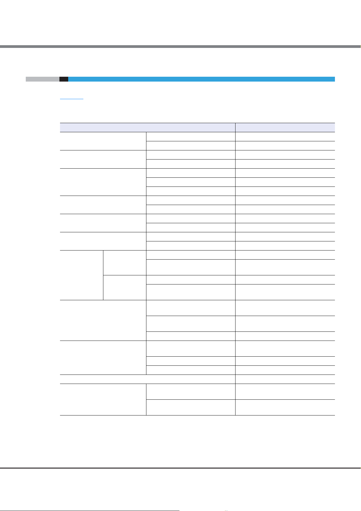
1.3 Specifications
1.3 Specifications
Table 1.1 shows the specifications of the power synchronized unit and the AC sensor unit.
Table 1.1 Specifications
Dimensions (W D H)
Weight
Power
Maximum power requirements
Maximum heat generation
Connection interface
Server UPS unit
Number of
connectable
devices
ETERNUS DX/AF
Cable length
Conditions to detect AC output
Support for a duplicated configuration Yes
Environmental condition
Item Specifications
Power synchronized unit 440 230 40 (mm) [1U]
AC sensor unit 100 150 40 (mm) [1U]
Power synchronized unit 4.0kg
AC sensor unit 1.3kg
Voltage AC100 - 120V, AC200 - 240V
Phase Single
Frequency 50Hz/60Hz
AC100 - 120V 3W
AC200 - 240V 7W
AC100 - 120V 11kJ/h
AC200 - 240V 26kJ/h
For ETERNUS DX/AF storage systems RS232C 4
For AC detection AC sensor 2
Basic 2
Maximum (when AC sensor units
are connected)
Basic 4
Maximum (when a cascade
connection is used)
Between a power synchronized unit
and an AC sensor unit (total)
Between a power synchronized unit
and the ETERNUS DX/AF
Between power synchronized units Max. 10m
Power consumption
Voltage AC100V / AC200V
Phase Single
Temperature
Humidity
0.1A or less AC output for one second or
5 - 40C (during operation)
0 - 50C (during non-operation)
20 - 80%RH (during operation)
8 - 80%RH (during non-operation)
16
8
Max. 100m
Max. 5m
more is detected.
23
FUJITSU Storage ETERNUS DX, ETERNUS AF Configuration Guide (Power Synchronized Unit)
Copyright 2017 FUJITSU LIMITED P3AM-8012-10ENZ0
Page 24
Chapter 1 Overview
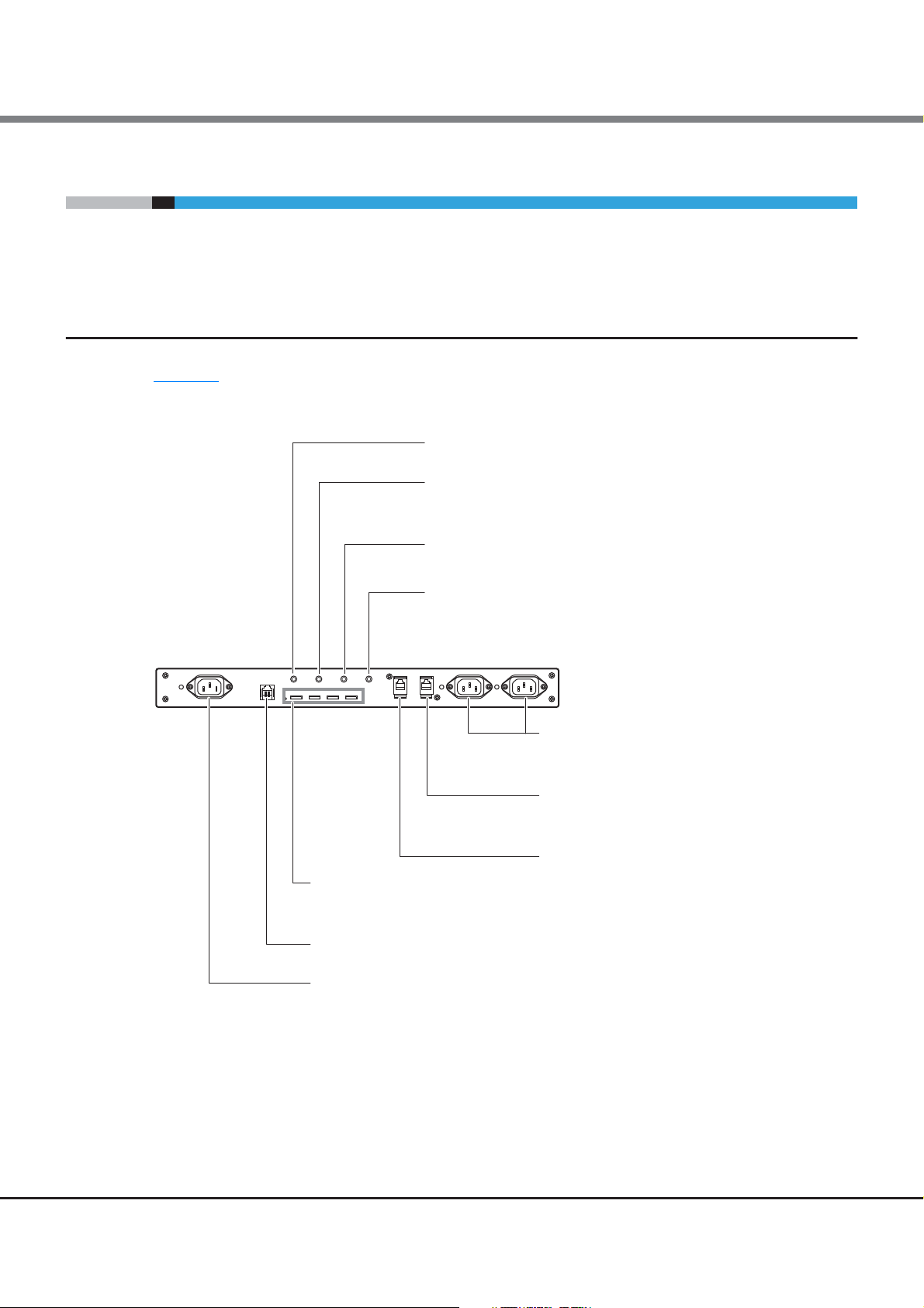
AC IN port
For power cord (for AC power input) connection
RCI port
Not used
PWC ports (#0, #1, #2, #3 from left)
For ETERNUS DX/AF connection with
RS232C cables to a power synchronized unit
AC SENSOR port
- For AC sensor unit connection
with an AC sensor port connection cable
to a power synchronized unit
- For cascading two power synchronized units
with a cascade cable to the AC SENSOR port
on the second power synchronized unit
CASCADE port
For cascading two power synchronized units
with a cascade cable to the CASCADE port
on the first power synchronized unit
SENSOR ports (left: #0, right: #1)
For power cord (for AC sensor) connection
to detect the power status of a server UPS unit
POWER LED
Displays the power status of a power synchronized unit
POWER SENSOR LED
Displays the detection status of AC output from
a server UPS unit
POWER CONTROL LED
Displays the power status of the connected ETERNUS DX/AF
CHECK LED
Displays the starting status of a power synchronized unit
1.4 Components
1.4 Components
This section describes the names and usage of the various components for the power synchronized unit and
the AC sensor unit.
1.4.1 Power Synchronized Unit
Figure 1.3 shows the names and usage of the various components for the power synchronized unit.
Figure 1.3 Components (power synchronized unit)
FUJITSU Storage ETERNUS DX, ETERNUS AF Configuration Guide (Power Synchronized Unit)
Copyright 2017 FUJITSU LIMITED P3AM-8012-10ENZ0
24
Page 25

Chapter 1 Overview
1.4 Components
Table 1.2 shows details about LEDs and the status of a power synchronized unit.
Table 1.2 Status and meanings of each LED (for power synchronized units)
LED name Function
POWER
(green)
POWER
SENSOR
(green)
POWER
CONTROL
(green)
CHECK
(Yellow)
Displays the power
status of the power
synchronized unit.
Displays that the power
synchronized unit has
commanded the
ETERNUS DX/AF to turn
on or off.
Displays the power
status of the ETERNUS
DX/AF.
Displays the starting
status of the power
synchronized unit.
LED
status
(off)
(on)
(blinks)
(off)
(on)
(off)
(on)
(blinks)
(off)
(on)
Power synchronized unit status
The power synchronized unit is off.
After the power synchronized unit is turned on, the
following condition for powering on the ETERNUS DX/AF is
detected.
• AC output from server UPS units using the SENSOR
port, the AC SENSOR port, or the CASCADE port
• Even though the power synchronized unit is turned on,
the following condition for powering on the ETERNUS
DX/AF is not detected.
- AC output from server UPS units using the SENSOR
port, the AC SENSOR port, or the CASCADE port
• The power synchronized unit is starting up.
The following condition is not detected and the power
synchronized unit commands the ETERNUS DX/AF to turn
off.
• AC output from server UPS units using the SENSOR
port, the AC SENSOR port, and the CASCADE port
The following condition is detected and the power
synchronized unit commands the ETERNUS DX/AF to turn
on.
• AC output from server UPS units using the SENSOR
port, the AC SENSOR port, or the CASCADE port
All of the ETERNUS DX/AF storage systems are off.
The ETERNUS DX/AF is on.
The ETERNUS DX/AF is still on even after the power
synchronized unit commands the ETERNUS DX/AF to turn
off (such as when shutting down the ETERNUS DX/AF).
The power synchronized unit is operating normally.
The power synchronized unit is starting up.
25
FUJITSU Storage ETERNUS DX, ETERNUS AF Configuration Guide (Power Synchronized Unit)
Copyright 2017 FUJITSU LIMITED P3AM-8012-10ENZ0
Page 26

Chapter 1 Overview
AC In port
For server UPS unit connection with
a power cord (for AC sensor) to an AC sensor unit
AC sensor output port
For power synchronized unit connection
with an AC sensor port connection cable
to an AC sensor unit
LED
Lights up green when AC output from
a server UPS unit is detected
1.4 Components
1.4.2 AC Sensor Unit (Optional)
Figure 1.4 shows the names and usage of the various components for the AC sensor unit.
Figure 1.4 Components (AC sensor unit)
Table 1.3
shows details about LEDs and the status of an AC sensor unit.
Table 1.3 Status and meanings of each LED (for AC sensor units)
LED name Function
Displays the AC output
LED
(green)
status of the
connected server UPS
unit.
LED
status
(off)
(on)
AC output from server UPS units using the AC In port is not
detected.
AC output from server UPS units using the AC In port is
detected.
AC sensor unit status
FUJITSU Storage ETERNUS DX, ETERNUS AF Configuration Guide (Power Synchronized Unit)
26
Copyright 2017 FUJITSU LIMITED P3AM-8012-10ENZ0
Page 27

Chapter 1 Overview
Server#0
UPS unit for
Server#0
UPS unit for
Server#1
Server#1
SENSOR#0 SENSOR#1
PWC#0
ETERNUS DX/AF
PWC
Power synchronized unit#0
#0 #1 #2 #3
Power cord (for AC sensor)
Power cord (for AC power input)
RS232C cable
Provided cables are indicated by solid lines.
Optional cables that can be added are indicated by dotted lines.
1.5 System Configuration
1.5 System Configuration
System configuration examples when the power synchronized unit is used are shown below.
The server UPS unit must have a function in the management software (PowerChute plus, etc.) that controls
the AC power output according to when the server powers on and off.
■ Power synchronization with two server UPS units
The following configuration is an example of power synchronization with two server UPS units.
One power synchronized unit can connect up to two server UPS units and four ETERNUS DX/AF storage
systems.
Figure 1.5 System configuration example (power synchronization with two server UPS units)
FUJITSU Storage ETERNUS DX, ETERNUS AF Configuration Guide (Power Synchronized Unit)
27
Copyright 2017 FUJITSU LIMITED P3AM-8012-10ENZ0
Page 28

Server#0
Server#1 Server#3 -
Server#2
CASCADE
AC SENSOR
Power synchronized unit#1 (*2)
#0 #1 #2 #3
SENSOR#0 SENSOR#1
AC SENSOR
AC sensor unit#0
AC sensor unit#1
PWC
~
~
Power synchronized unit#0
#0 #1 #2 #3
UPS unit for
Server#1
UPS unit for
Server#0
UPS unit for
Server#3 -
UPS unit for
Server#2
*1: Do not attach a termination resistor to
the branch connector on the AC sensor unit.
*2: For a cascade connection, do not connect
the server UPS unit to power synchronized
unit#1.
(*1)
ETERNUS DX/AF
#0
PWC
ETERNUS DX/AF
#1
PWC
ETERNUS DX/AF
#2
PWC
ETERNUS DX/AF
#3
PWC
ETERNUS DX/AF
#4
PWC
ETERNUS DX/AF
#5
PWC
ETERNUS DX/AF
#6
PWC
ETERNUS DX/AF
#7
PWC
PWC
Cascade cable
AC sensor port connection cable
RS232C cable
Provided cables are indicated by solid lines.
Optional cables that can be added are indicated by dotted lines.
Power cord (for AC sensor)
Power cord (for AC power input)
Chapter 1 Overview
1.5 System Configuration
■ Power synchronization with three or more server UPS units
The following configuration is an example of power synchronization with three or more server UPS units.
Up to 16 server UPS units can be connected by using optional AC sensor units. By cascading two power
synchronized units, up to eight ETERNUS DX/AF storage systems can be connected.
Figure 1.6 System configuration example (power synchronization with three or more server UPS units)
FUJITSU Storage ETERNUS DX, ETERNUS AF Configuration Guide (Power Synchronized Unit)
28
Copyright 2017 FUJITSU LIMITED P3AM-8012-10ENZ0
Page 29

Chapter 1 Overview
ETERNUS DX/AF
PWC
Power synchronized unit
PWC
UPS unit for
Server#0
Server#0
UPS unit for
Server#1
4
5
3, 6
3, 6
2
2
UPS management
software
Server#1
UPS management
software
ETERNUS DX/AF
UPS unit
UPS settingUPS setting
RS232C cable
An instruction is
issued to turn on the
ETERNUS DX/AF
when AC output is
detected.
1
1.6 Power Management for Power Synchronization
1.6 Power Management for Power Synchronization
This section explains power management with a power synchronized unit.
The power synchronized unit detects the AC power output of the target devices for power synchronization and
commands the ETERNUS DX/AF to synchronize the power with the target devices.
When the power synchronized unit detects the AC power output of any server UPS unit, the power
synchronized unit commands the ETERNUS DX/AF to turn on.
When the power synchronized unit does not detect AC power output in any of the server UPS units, the power
synchronized unit commands the ETERNUS DX/AF to turn off.
The server UPS unit must have a function in the management software that controls the AC power output
according to when the server powers on and off. The server UPS unit must have one unused outlet to connect
to the power synchronized unit.
Connect the power cords of the ETERNUS DX/AF and the power synchronized unit to a UPS (UPS for the
ETERNUS DX/AF) that uses a power line that is not the same as the server UPS unit. This enables power to be
supplied or stopped according to the scheduled operations and the power failure settings of the server.
■ Powering on sequence for turning on power or power recovery
Figure 1.7 Power on using a power synchronized unit
1 Power on of an ETERNUS DX/AF UPS unit
2 Issuance of command to turn on the server (power on of the server UPS units)
3 Server startup (OS startup is suspended)
The server OS startup is suspended until the ETERNUS DX/AF startup is complete. For the set suspend
time of the server, refer to "Figure 1.8
(powering on)" (page 30).
Operation timing chart when using a power synchronized unit
29
FUJITSU Storage ETERNUS DX, ETERNUS AF Configuration Guide (Power Synchronized Unit)
Copyright 2017 FUJITSU LIMITED P3AM-8012-10ENZ0
Page 30

Chapter 1 Overview
1.6 Power Management for Power Synchronization
4 Issuance of command to turn on the ETERNUS DX/AF from the power synchronized unit
5 ETERNUS DX/AF startup
6 Server OS startup
The following figure shows the timing chart of power on operations for scheduled operations and power
recovery. For details about setting items and values, refer to the manual of the expansion card that is
installed in the UPS unit and the manual of the UPS management software that is used.
Figure 1.8 Operation timing chart when using a power synchronized unit (powering on)
2 Issuance of command to turn on the server
S1 (>E1)
Server
Server UPS unit
ETERNUS DX/AF
ETERNUS DX/AF
UPS unit
S1: Waiting time interval starting from when the command is issued to turn on the server to the beginning of the OS startup process.
Set a longer time than the time that is required to complete ETERNUS DX/AF startup (E1).
E1: Time that is required to complete ETERNUS DX/AF startup from the start of powering on of the ETERNUS DX/AF.
For details, refer to the manual that is provided with the connected ETERNUS DX/AF.
Shutdown state
2 Power on of the server UPS unit (Power supply starts)
OFF
4 Issuance of command to turn on the ETERNUS DX/AF from the power synchronized unit
1 Power on of an ETERNUS DX/AF UPS unit (Power supply starts)
OFF
3 OS startup suspension
E1
5 Startup Operating
6 OS startup
ON
ON
Operating
30
FUJITSU Storage ETERNUS DX, ETERNUS AF Configuration Guide (Power Synchronized Unit)
Copyright 2017 FUJITSU LIMITED P3AM-8012-10ENZ0
Page 31

Chapter 1 Overview
ETERNUS DX/AF
PWC
Power synchronized unit
PWC
UPS unit for
Server#0
Server#0
UPS unit for
Server#1
3
4
1 1
2 2
5
UPS management
software
Server#1
UPS management
software
ETERNUS DX/AF
UPS unit
UPS settingUPS setting
RS232C cable
An instruction is issued
to turn off the
ETERNUS DX/AF
when no AC output is
detected.
1.6 Power Management for Power Synchronization
■ Powering off sequence for turning off power or power recovery
Figure 1.9 Power off using a power synchronized unit
(0 Power failure occurred (commercial power is stopped))
1 Shutdown of all the servers
2 Shutdown of all the server UPS units
3 Issuance of command to turn off the ETERNUS DX/AF from the power synchronized unit
4 ETERNUS DX/AF shutdown
5 Shutdown of the ETERNUS DX/AF UPS unit
31
FUJITSU Storage ETERNUS DX, ETERNUS AF Configuration Guide (Power Synchronized Unit)
Copyright 2017 FUJITSU LIMITED P3AM-8012-10ENZ0
Page 32

Chapter 1 Overview
Shutdown state
Operating
ON
OFF
OFF
ON OFF
ETERNUS DX/AF
Server UPS unit
Server
ETERNUS DX/AF
UPS unit
1 Shutdown of the server
(Server shutdown starts)
3 Issuance of command to shut down the ETERNUS DX/AF
from the power synchronized unit
S3 (>S2)
S2
E3 (>S3+E2)
Operating (Power is on)
E2
5 UPS shutdown
(Power supply stops)
S2: Processing time for server shutdown.
E2: Required time to turn off the ETERNUS DX/AF.
For details, refer to the manual that is provided with the connected ETERNUS DX/AF.
S3: Battery operation time until server UPS unit shutdown when a power failure occurs.
E3: Battery operation time until ETERNUS DX/AF UPS unit shutdown when a power failure occurs.
Shutdown process
4 Shutdown process
2 UPS shutdown
(Power supply stops)
(0 Power failure occurred (commercial power is stopped))
1.6 Power Management for Power Synchronization
The following figure shows the timing chart of power off operations for scheduled operations or for when a
power failure occurs. For details about setting items and values, refer to the manual of the expansion card
that is installed in the UPS unit and the manual of the UPS management software that is used.
Figure 1.10 Operation timing chart when using a power synchronized unit (powering off)
FUJITSU Storage ETERNUS DX, ETERNUS AF Configuration Guide (Power Synchronized Unit)
32
Copyright 2017 FUJITSU LIMITED P3AM-8012-10ENZ0
Page 33

Chapter 2
Installation
This chapter describes the installation procedures for the power synchronized unit and the AC sensor unit.
Make sure to check "
Safety Precautions" (page 9) before installation.
2.1 Package Contents Check
Check the list of package contents in Table 2.1 and Table 2.2 to confirm that there are no missing parts.
If there are missing parts, contact your sales representative.
Table 2.1 List of package contents (power synchronized unit)
Package contents Quantity Note
Power synchronized unit 1 —
RS232C cable 2
Rack mount kit One set —
Safety Precautions 1 —
Read Me First 1 —
Table 2.2 List of package contents (AC sensor unit)
1m
For ETERNUS DX/AF connection
Package contents Quantity Note
AC sensor unit 1 —
AC sensor port connection cable 1
Branch connector 1 —
Rubber foot 4
Rack mount kit One set —
4m
For power synchronized unit connection
This is not used when the AC sensor unit is installed in a
rack.
33
FUJITSU Storage ETERNUS DX, ETERNUS AF Configuration Guide (Power Synchronized Unit)
Copyright 2017 FUJITSU LIMITED P3AM-8012-10ENZ0
Page 34

Chapter 2 Installation
2.2 Preparation
2.2 Preparation
2.2.1 Installation Area
■ Placement area
Refer to the placement area of the rack to install the power synchronized unit and the AC sensor unit.
■ Installation condition
Install the power synchronized unit and the AC sensor unit in an area that meets all the conditions described
in "
Instructions for installation" (page 10) of "Safety Precautions".
2.2.2 Checking Power Sockets and Server UPS Unit Outlets
Check the required number and specifications of power sockets and server UPS unit outlets.
• One power socket is required for each power synchronized unit. Make sure to check the plug type of the
power socket.
Connect the power synchronized unit to the same power socket line as the ETERNUS DX/AF.
• Make sure each server UPS unit has an unused outlet for connecting a power synchronized unit or an AC
sensor unit. In addition, make sure to check the plug type of the outlet.
2.2.3 Preparing Power Cords
Note that power cords (for AC power input) for power synchronized units and power cords (for AC sensor) to
connect server UPS units to power synchronized units or AC sensor units are not supplied with power
synchronized units.
The IEC 60320-C14 port type is used for the AC IN ports and the SENSOR ports of the power synchronized units.
This port type is also used for the AC IN ports of the AC sensor units.
Check the specifications of the power sockets and server UPS unit outlets that are to be used for the power
synchronized units and AC sensor units. Prepare the required number of appropriate power cords.
• Power cord (for AC power input)
- Each power synchronized unit requires one power cord.
- The voltage for the AC IN port is 10A 250V or less.
• Power cord (for AC sensor)
- Each server UPS unit that is to be connected to the power synchronized unit requires one power cord.
- Each AC sensor unit requires one power cord.
Be sure that the power cords have the approval of the appropriate safety agencies of the country where the
equipment will be used.
34
FUJITSU Storage ETERNUS DX, ETERNUS AF Configuration Guide (Power Synchronized Unit)
Copyright 2017 FUJITSU LIMITED P3AM-8012-10ENZ0
Page 35

Chapter 2 Installation
WARNING
Do Not
CAUTION
Do
2.3 Installing in a Rack
• Do not use a power cord that does not satisfy the specifications of the power
synchronized unit and the AC sensor unit. Doing so may cause failure, fire, or
electric shock.
2.3 Installing in a Rack
This section explains how to install a power synchronized unit and an AC sensor unit in a rack.
Make sure to check "
sensor unit in a rack. Also refer to the manual that is provided with the racks.
Safety Precautions" (page 9) before installing the power synchronized unit and the AC
• If the power synchronized unit and the AC sensor unit are installed or
disassembled other than as described in this manual, device failure or electric
shock may occur.
• The power synchronized unit contains delicate components, and should be
handled gently. Do not drop or knock the power synchronized unit against the
rack during installation.
• Install the blank panels provided with the rack where no other devices are
installed.
• Especially for an enclosed rack with doors, or when multiple devices are to be
mounted and running, it is important to realize that the temperature inside
the cabinet will be considerably higher than that of the room. Make sure the
rack internal ambient temperatures do not exceed the environmental
conditions for temperature described in "1.3
to do so may damage the power synchronized unit.
Specifications" (page 23). Failure
• When installing the power synchronized unit with other devices into the same
rack, the airflow of the device installed on and under the power synchronized
unit may interfere with each other and reduce the effect of device cooling.
Make sure to leave plenty of room between the devices if required. Failure to
do so may damage the power synchronized unit and lead to malfunction.
• Do not obstruct the air vents in the power synchronized unit.
35
FUJITSU Storage ETERNUS DX, ETERNUS AF Configuration Guide (Power Synchronized Unit)
Copyright 2017 FUJITSU LIMITED P3AM-8012-10ENZ0
Page 36

Chapter 2 Installation
Procedure
(Rear rack pillars)
Base line of
power synchronized unit
1st position
3rd position
1U (power synchronized unit size)
2.3 Installing in a Rack
2.3.1 Installing a Power Synchronized Unit
This section describes how to install a power synchronized unit in a rack.
■ Checking the package contents of the rack mount kit
Check the following package contents to confirm that there are no missing parts. If there are missing parts,
contact your sales representative.
❏ L-shaped bracket: 2
Same for right and left.
❏ M6 cross recessed head screw
with captive washer: 4
❏ M3 flat head screw: 4
For attaching L-shaped
brackets
❏ Blank panel: 1
■ Procedure for installing a power synchronized unit
1 Open the front and rear doors of the rack.
2 Attach the M6 cage nuts to the rear rack pillar.
❏ M6 cage nut: 4
Used when the holes in the rack
pillars are square
• Attachment positions
Insert four M6 cage nuts in the 1st and 3rd holes above the power synchronized unit base line.
36
FUJITSU Storage ETERNUS DX, ETERNUS AF Configuration Guide (Power Synchronized Unit)
Copyright 2017 FUJITSU LIMITED P3AM-8012-10ENZ0
Page 37

Chapter 2 Installation
Top view
M6 cage nut
Rack pillar (square)
M3 flat head screws
L-shaped bracket
M3 flat head screws
L-shaped bracket
(Rear rack pillars)
M6 cross recessed head screws
with captive washer
M6 cross recessed head
screws with captive washer
2.3 Installing in a Rack
3 Attach the L-shaped brackets to the power synchronized unit.
• Attachment procedure
Clip the M6 cage nut tabs into the desired hole from the inside.
Use four M3 flat head screws to attach the L-shaped brackets to the power synchronized unit on both
sides.
4 Install the power synchronized unit in the rack.
Use four M6 cross recessed head screws with captive washer to fasten the power synchronized unit in
the rack.
37
FUJITSU Storage ETERNUS DX, ETERNUS AF Configuration Guide (Power Synchronized Unit)
Copyright 2017 FUJITSU LIMITED P3AM-8012-10ENZ0
Page 38

Chapter 2 Installation
End of procedure
(Front rack pillars)
(Rear rack pillars)
Blank panel
2.3 Installing in a Rack
5 Attach the blank panel to the rack front.
The blank panel should be attached at the same height as the power synchronized unit.
38
FUJITSU Storage ETERNUS DX, ETERNUS AF Configuration Guide (Power Synchronized Unit)
Copyright 2017 FUJITSU LIMITED P3AM-8012-10ENZ0
Page 39

Chapter 2 Installation
2.3 Installing in a Rack
2.3.2 Installing an AC Sensor Unit
This section describes how to install an AC sensor unit in a rack.
Install the AC sensor unit in the same rack as the server UPS unit. When installing the AC sensor unit, the
length of the power cord (for AC sensor) that connects the AC sensor unit and the server UPS unit must be
taken into consideration.
■ Checking the package contents of the rack mount kit
Check the following package contents to confirm that there are no missing parts. If there are missing parts,
contact your sales representative.
❏ Shelf plate: 1 ❏ L-shaped bracket: 2
❏ M4 cross recessed head screw
with captive washer: 2
❏ M6 cross recessed head screw
with captive washer: 4
❏ M3 cross recessed head screw
with captive washer: 4
❏ Blank panel: 1
Same for right and left.
❏ M6 cage nut: 4
Used when the holes in the
rack pillars are square
39
FUJITSU Storage ETERNUS DX, ETERNUS AF Configuration Guide (Power Synchronized Unit)
Copyright 2017 FUJITSU LIMITED P3AM-8012-10ENZ0
Page 40

Chapter 2 Installation
Procedure
(Rear rack pillars)
Base line of AC sensor unit
1st position
3rd position
1U (AC sensor unit size)
Top view
M6 cage nut
Rack pillar (square)
M3 cross recessed head screws
with captive washer
L-shaped bracket
L-shaped bracket
M3 cross recessed head
screws with captive washer
2.3 Installing in a Rack
■ Procedure for installing an AC sensor unit
1 Open the front and rear doors of the rack.
2 Attach the M6 cage nuts to the rear rack pillar.
• Attachment positions
Insert four M6 cage nuts in the 1st and 3rd holes above the AC sensor unit base line.
• Attachment procedure
Clip the M6 cage nut tabs into the desired hole from the inside.
3 Attach the L-shaped brackets to the AC sensor unit.
Use four M3 cross recessed head screws with captive washer to attach the L-shaped brackets to the AC
sensor unit on both sides.
40
FUJITSU Storage ETERNUS DX, ETERNUS AF Configuration Guide (Power Synchronized Unit)
Copyright 2017 FUJITSU LIMITED P3AM-8012-10ENZ0
Page 41

Chapter 2 Installation
M4 cross recessed head screws with captive washer
Shelf plate
(Rear rack pillars)
M6 cross recessed head screws
with captive washer
M6 cross recessed head screws
with captive washer
2.3 Installing in a Rack
4 Attach the shelf plate to the AC sensor unit.
Use two M4 cross recessed head screws with captive washer to attach the shelf plate to the AC sensor
unit.
Up to two AC sensor units can be attached to the same shelf plate. Attach the first AC sensor unit on
the right side when facing the shelf plate as shown in the figure above.
5 Attach the shelf plate to the rack.
Use four M6 cross recessed head screws with captive washer to fasten the shelf plate in the rack.
FUJITSU Storage ETERNUS DX, ETERNUS AF Configuration Guide (Power Synchronized Unit)
41
Copyright 2017 FUJITSU LIMITED P3AM-8012-10ENZ0
Page 42

Chapter 2 Installation
End of procedure
(Front rack pillars)
(Rear rack pillars)
Blank panel
2.3 Installing in a Rack
6 Attach the blank panel to the rack front.
The blank panel should be attached at the same height as the AC sensor unit.
42
FUJITSU Storage ETERNUS DX, ETERNUS AF Configuration Guide (Power Synchronized Unit)
Copyright 2017 FUJITSU LIMITED P3AM-8012-10ENZ0
Page 43

Chapter 3
Powering On and Off
This chapter explains how to turn on and off the power synchronized unit.
■ Powering on
When a power cord (for AC power input) is connected to the AC IN port and the power socket, the power
synchronized unit turns on.
For details about how to connect a power cord (for AC power input), refer to "4.2
Synchronized Unit" (page 50).
■ Powering off
When a power cord (for AC power input) is disconnected from the AC IN port, the power synchronized unit
turns off.
Turning on the Power
For normal operation, there is no need to turn the power off.
If the power synchronized unit must be turned off, such as before any inspections of power supply devices are
performed, check that the power synchronized unit and the devices that connect the power synchronized
unit are all turned off before disconnecting the power cords (for AC power input).
43
FUJITSU Storage ETERNUS DX, ETERNUS AF Configuration Guide (Power Synchronized Unit)
Copyright 2017 FUJITSU LIMITED P3AM-8012-10ENZ0
Page 44

Chapter 4
Procedure
End of procedure
Connection and Settings
This chapter describes the installation and setting procedures for a power synchronized unit and an AC sensor
unit.
If your sales representative or maintenance engineer does not perform the settings of the power synchronized
unit and the AC sensor unit, perform the settings yourself.
Attach labels to each cable that is to be connected and make a note of the connection source and
destination. This helps with cable management and prevents incorrect connections.
For the connection and setting details of a device that is connected to the power synchronized unit, refer to
the manual that is provided with the connected device.
■ Workflow
Perform the following procedure for connection and settings:
1 Set the ETERNUS DX/AF.
For details, refer to "4.1 Setting the ETERNUS DX/AF" (page 45).
2 Turn on the power synchronized unit.
For details, refer to "4.2 Turning on the Power Synchronized Unit" (page 50).
3 When five or more ETERNUS DX/AF storage systems are installed, connect the cascade
cables.
For details, refer to "4.3 Connecting Cascade Cables" (page 53).
4 Connect the power synchronized unit to the server UPS unit.
For details, refer to "4.4.1 Connecting the Server UPS Unit to the Power Synchronized Unit" (page 57).
5 When three or more server UPS units are connected, connect the AC sensor unit.
For details, refer to "4.4.2 Connecting the AC Sensor Unit" (page 58).
6 Connect the power synchronized unit to the ETERNUS DX/AF.
For details, refer to "4.5 Connecting to the ETERNUS DX/AF" (page 61).
44
FUJITSU Storage ETERNUS DX, ETERNUS AF Configuration Guide (Power Synchronized Unit)
Copyright 2017 FUJITSU LIMITED P3AM-8012-10ENZ0
Page 45

Chapter 4 Connection and Settings
4.1 Setting the ETERNUS DX/AF
4.1 Setting the ETERNUS DX/AF
Perform the necessary settings for power synchronization by using the setting and maintenance program of
the ETERNUS DX/AF.
If the power synchronized unit and the ETERNUS DX/AF storage system are connected with a redundant
configuration, the operations during a power down are as follows:
• For the ETERNUS DX60 S4/DX100 S4/DX200 S4, ETERNUS DX500 S4/DX600 S4, ETERNUS DX60 S3/DX100
S3/DX200 S3, ETERNUS DX500 S3/DX600 S3, ETERNUS DX8100 S3, ETERNUS AF250 S2/AF650 S2, ETERNUS
AF250/AF650, ETERNUS DX200F, and ETERNUS DX60 S2/DX80 S2/DX90 S2
When the controllers for CM#0 and CM#1 both receive shutdown instructions, the shutdown process
starts.
• For the ETERNUS DX8700 S3/DX8900 S3
When the Service Controllers (SVC) for SVC#0 and SVC#1 both receive shutdown instructions, the
shutdown process starts.
■ ETERNUS DX60 S4/DX100 S4/DX200 S4, ETERNUS DX500 S4/DX600 S4, ETERNUS DX60 S3/
DX100 S3/DX200 S3, ETERNUS DX500 S3/DX600 S3, ETERNUS DX8100 S3, ETERNUS AF250
S2/AF650 S2, ETERNUS AF250/AF650, and ETERNUS DX200F
This section explains the setting items on the power synchronization setting screen for the ETERNUS DX60 S4/
DX100 S4/DX200 S4, ETERNUS DX500 S4/DX600 S4, ETERNUS DX60 S3/DX100 S3/DX200 S3, ETERNUS DX500
S3/DX600 S3, ETERNUS DX8100 S3, ETERNUS AF250 S2/AF650 S2, ETERNUS AF250/AF650, and ETERNUS
DX200F.
Figure 4.1 ETERNUS DX60 S4/DX100 S4/DX200 S4, ETERNUS DX500 S4/DX600 S4, ETERNUS DX60 S3/DX100
S3/DX200 S3, ETERNUS DX500 S3/DX600 S3, ETERNUS DX8100 S3, ETERNUS AF250 S2/AF650 S2,
ETERNUS AF250/AF650, and ETERNUS DX200F setup (Setup Power Management screen)
45
FUJITSU Storage ETERNUS DX, ETERNUS AF Configuration Guide (Power Synchronized Unit)
Copyright 2017 FUJITSU LIMITED P3AM-8012-10ENZ0
Page 46

Chapter 4 Connection and Settings
4.1 Setting the ETERNUS DX/AF
• Auto Power
Select "Disable".
• Power Resume
Select "Disable".
• Connection CM
Select the controllers (CM#0 and/or CM#1) of the ETERNUS DX60 S4/DX100 S4/DX200 S4, ETERNUS DX500
S4/DX600 S4, ETERNUS DX60 S3/DX100 S3/DX200 S3, ETERNUS DX500 S3/DX600 S3, ETERNUS AF250 S2/
AF650 S2, ETERNUS AF250/AF650, and ETERNUS DX200F that are connected to the power synchronized
unit with the RS232C cable.
Select "CM#0" when the power synchronized unit is connected to the PWC port on controller 0. Select
"CM#1" when the power synchronized unit is connected to the PWC port on controller 1.
When different power synchronized units are connected to controller 0 and controller 1 in a duplicated
configuration, select both "CM#0" and "CM#1".
• Delay until Shutdown
Do not change the default setting (0 minute).
• Set management unit interface
Select "Power Synchronized Unit".
• Power Failure Signal
"Positive" (positive logic) is automatically set.
• Low Battery Signal
"Negative" (negative logic) is automatically set.
• UPS Shutdown Signal
Do not select the "Enable" checkbox.
"Positive" (positive logic) is set by default.
46
FUJITSU Storage ETERNUS DX, ETERNUS AF Configuration Guide (Power Synchronized Unit)
Copyright 2017 FUJITSU LIMITED P3AM-8012-10ENZ0
Page 47

Chapter 4 Connection and Settings
4.1 Setting the ETERNUS DX/AF
■ ETERNUS DX8700 S3/DX8900 S3
This section explains the setting items on the power synchronization setting screen for the ETERNUS DX8700
S3/DX8900 S3.
Figure 4.2 ETERNUS DX8700 S3/DX8900 S3 setup (Setup Power Management screen)
• Auto Power
Select "Disable".
• Power Resume
Select "Disable".
• Connection SVC
Select the SVCs (SVC#0 and/or SVC#1) of the ETERNUS DX8700 S3/DX8900 S3 that are connected to the
power synchronized unit with the RS232C cable.
Select "SVC#0" when the power synchronized unit is connected to the PWC port on SVC#0. Select "SVC#1"
when the power synchronized unit is connected to the PWC port on SVC#1.
When different power synchronized units are connected to SVC#0 and SVC#1 in a duplicated configuration,
select both "SVC#0" and "SVC#1".
• Delay until Shutdown
Do not change the default setting (0 minute).
• Set management unit interface
Select "Power Synchronized Unit".
• Power Failure Signal
"Positive" (positive logic) is automatically set.
• Low Battery Signal
"Negative" (negative logic) is automatically set.
• UPS Shutdown Signal
Do not select the "Enable" checkbox.
"Positive" (positive logic) is set by default.
47
FUJITSU Storage ETERNUS DX, ETERNUS AF Configuration Guide (Power Synchronized Unit)
Copyright 2017 FUJITSU LIMITED P3AM-8012-10ENZ0
Page 48

Chapter 4 Connection and Settings
4.1 Setting the ETERNUS DX/AF
■ ETERNUS DX80 S2/DX90 S2
This section explains the setting items on the power synchronization setting screen for the ETERNUS DX80 S2/
DX90 S2.
Figure 4.3 ETERNUS DX80 S2/DX90 S2 setup (Setup Power Management screen)
• Enable
Select the controllers (CM#0 and/or CM#1) of the ETERNUS DX80 S2/DX90 S2 that are connected to the
power synchronized unit with the RS232C cable.
Select "CM#0" when the power synchronized unit is connected to the PWC port on controller 0. Select
"CM#1" when the power synchronized unit is connected to the PWC port on controller 1.
When different power synchronized units are connected to controller 0 and controller 1 in a duplicated
configuration, select both "CM#0" and "CM#1".
• Delay until Shutdown (min.)
Do not change the default setting (0 minute).
• Set management unit interface
Select "Power Synchronized Unit".
• Power Failure Signal
"Positive" (positive logic) is automatically set.
• Low Battery Signal
"Negative" (negative logic) is automatically set.
• UPS Shutdown Signal
Do not select the "Enable" checkbox.
"Positive" (positive logic) is set by default.
• Auto Power
Select "Disable".
• Power Resume
Select "Disable".
48
FUJITSU Storage ETERNUS DX, ETERNUS AF Configuration Guide (Power Synchronized Unit)
Copyright 2017 FUJITSU LIMITED P3AM-8012-10ENZ0
Page 49

Chapter 4 Connection and Settings
4.1 Setting the ETERNUS DX/AF
■ ETERNUS DX60 S2
This section explains the setting items on the power synchronization setting screen for the ETERNUS DX60 S2.
Figure 4.4 ETERNUS DX60 S2 setup (Setup Power Management screen)
• Enable
Select the controllers (CM#0 and/or CM#1) of the ETERNUS DX60 S2 that are connected to the power
synchronized unit with the RS232C cable. Select "CM#0" when the power synchronized unit is connected to
the PWC port on controller 0. Select "CM#1" when the power synchronized unit is connected to the PWC port
on controller 1.
When different power synchronized units are connected to controller 0 and controller 1 in a duplicated
configuration, select both "CM#0" and "CM#1".
• Delay until Shutdown (min.)
Do not change the default setting (0 minute).
• Set management unit interface
Select "Power Synchronized Unit".
• Power Failure Signal
"Positive" (positive logic) is automatically set.
• Low Battery Signal
"Negative" (negative logic) is automatically set.
• UPS Shutdown Signal
Do not select the "Enable" checkbox.
"Positive" (positive logic) is set by default.
49
FUJITSU Storage ETERNUS DX, ETERNUS AF Configuration Guide (Power Synchronized Unit)
Copyright 2017 FUJITSU LIMITED P3AM-8012-10ENZ0
Page 50

Chapter 4 Connection and Settings
WARNING
Do Not
Unplug
CAUTION
Ground
4.2 Turning on the Power Synchronized Unit
4.2 Turning on the Power Synchronized Unit
Connect the power cord (for AC power input) to the power synchronized unit to turn on the power
synchronized unit.
Each power synchronized unit requires a power cord (for AC power input).
Power cords (for AC power input) must be obtained by customers.
• Do not handle the power plug with wet hands. Doing so may cause electric
shock.
• Do not damage or modify the power cord or the power plug. Heating, forced
bending, twisting, pulling, or placing heavy objects on the power cord or the
power plug will damage it, causing electric shock or fire.
• Do not wind power cords too tightly at the root of the power cord. Doing so
stresses the cords and may expose or snap the inner wires, which can lead to
electric shock or fire.
• Do not use the power cord or the power plug if it is damaged or the plug does
not snugly fit into the socket. Doing so may cause electric shock or fire.
• Do not use a power cord that does not satisfy the specifications of the power
synchronized unit and the AC sensor unit. Doing so may cause electric shock,
fire, or device failure.
• Use a dry cloth to remove all dust from plugs and power sockets. Not doing so
may cause electric shock or fire.
• Use only power sockets that have a ground. Failure to do so may cause electric
shock, fire, or malfunction.
50
FUJITSU Storage ETERNUS DX, ETERNUS AF Configuration Guide (Power Synchronized Unit)
Copyright 2017 FUJITSU LIMITED P3AM-8012-10ENZ0
Page 51

Chapter 4 Connection and Settings
Procedure
AC IN port
Power cord (for AC power input)
Release tie
4.2 Turning on the Power Synchronized Unit
■ Procedure for powering on
The procedure for turning on a power synchronized unit is described below.
1 Connect the power cord (for AC power input) to the power synchronized unit.
1-1 Connect the power plug of the power cord (for AC power input) to the AC IN port.
1-2 Attach the release tie to the plug of the power cord (for AC power input) to firmly fix the power plug
to ensure it does not become unplugged.
2 Connect the power plug at the other end of the power cord to the power socket.
When the power plug is connected to the power socket, the power synchronized unit is turned on.
Check that the CHECK LED is off and the POWER LED is blinking green on the power synchronized unit.
Connect the power plug to the power socket that belongs to the same power line as
the ETERNUS DX/AF. Do not connect the power plug to a server UPS unit.
FUJITSU Storage ETERNUS DX, ETERNUS AF Configuration Guide (Power Synchronized Unit)
51
Copyright 2017 FUJITSU LIMITED P3AM-8012-10ENZ0
Page 52

Chapter 4 Connection and Settings
End of procedure
CAUTION
Do
Unplug
4.2 Turning on the Power Synchronized Unit
• Ensure the power plug is fully inserted into the socket. Failure to do so
may cause electric shock or fire.
• Do not use the server service outlet to connect the power cord for the
power synchronized unit.
• Do not overload electrical sockets. Doing so may cause electric shock or
fire.
• When unplugging the power cord, hold the plug. Do not pull on the
cord. Pulling the cord may expose or snap the inner wires, which may
cause electric shock or fire.
• When the power synchronized unit is not used for a long period of time,
unplug all power plugs. Failure to do so may lead to fire.
52
FUJITSU Storage ETERNUS DX, ETERNUS AF Configuration Guide (Power Synchronized Unit)
Copyright 2017 FUJITSU LIMITED P3AM-8012-10ENZ0
Page 53

Chapter 4 Connection and Settings
CAUTION
Do
Power synchronized unit#1
Power synchronized unit#0
Server#0
UPS unit for
Server#0
Server#1
UPS unit for
Server#1
Cascade cable
(optional)
Power cord (for AC sensor)
AC SENSOR port
CASCADE port
SENSOR ports
4.3 Connecting Cascade Cables
4.3 Connecting Cascade Cables
When two power synchronized units are cascaded, use the cascade cable to connect the power synchronized
units.
Cascade cables must be purchased separately.
A connection figure for the cascade cable is shown below.
Figure 4.5 Cascade cable connection
• When the power synchronized units are cascaded, the unit that is connected to the server UPS unit is
"power synchronized unit#0".
• Do not attach a branch connector or a termination resistor to the CASCADE port or the AC SENSOR port.
Doing so makes operations unstable.
• When connecting external (signal, power, etc.) cables, avoid placing stress on
them. Not doing so may damage the cables.
FUJITSU Storage ETERNUS DX, ETERNUS AF Configuration Guide (Power Synchronized Unit)
53
Copyright 2017 FUJITSU LIMITED P3AM-8012-10ENZ0
Page 54

Chapter 4 Connection and Settings
Procedure
CAUTION
Do Not
90
Do not bend
more than 90 degrees
Do not fold
Power synchronized unit#0
CASCADE port
Cascade cable
4.3 Connecting Cascade Cables
■ Procedure for cascade cable connection
The procedure for connecting a cascade cable is described below.
When connecting the cascade cable, check the direction of the connector tab and firmly insert it all the way
in.
When disconnecting a cascade cable, hold the tab of the connector while pulling it out.
• Do not forcibly bend or fold the cable. Doing so may damage the cable and
cause the power synchronized unit to malfunction.
1 Connect the cascade cable to power synchronized unit#0.
Connect the cascade cable connector to the CASCADE port.
2 Check that power synchronized unit#1 is turned on.
Check that the CHECK LED is off and the POWER LED is blinking green on the power synchronized unit.
54
FUJITSU Storage ETERNUS DX, ETERNUS AF Configuration Guide (Power Synchronized Unit)
Copyright 2017 FUJITSU LIMITED P3AM-8012-10ENZ0
Page 55

Chapter 4 Connection and Settings
End of procedure
Power synchronized unit#1
Cascade cable
AC SENSOR port
4.3 Connecting Cascade Cables
3 Connect the connector at the other end to power synchronized unit#1.
Connect the connector at the other end of the cascade cable to the AC SENSOR port.
55
FUJITSU Storage ETERNUS DX, ETERNUS AF Configuration Guide (Power Synchronized Unit)
Copyright 2017 FUJITSU LIMITED P3AM-8012-10ENZ0
Page 56

Chapter 4 Connection and Settings
Power synchronized unit
Server#3
Server#2
UPS unit for
Server#2
UPS unit for
Server#3
Server#1
Server#0
UPS unit for
Server#1
UPS unit for
Server#0
AC sensor unit
Power cord (for AC sensor)
(Must be obtained by customers)
Power cord (for AC sensor)
(Must be obtained by customers)
AC sensor port connection cable
(provided with an AC sensor unit)
....
SENSOR#0 port SENSOR#1 port
AC In port
Branch connector
AC SENSOR port
4.4 Connecting to the Server UPS Unit
4.4 Connecting to the Server UPS Unit
Connect the server UPS unit to the power synchronized unit.
When three or more server UPS units are connected or when the server UPS unit is placed beyond the reach of
a power cord (for AC sensor), use the AC sensor unit.
The following figure shows server UPS unit and AC sensor unit connection.
Figure 4.6 Connection for the server UPS units and the AC sensor units
The power cord (for AC sensor) that is connected to a server UPS unit is a cable for detecting the AC output
status of a server UPS unit. This cable does not supply AC power to the power synchronized unit.
For details about settings for a server UPS unit that is connected to the power synchronized unit, refer to the
manual that is provided with the server UPS unit and perform the appropriate settings.
FUJITSU Storage ETERNUS DX, ETERNUS AF Configuration Guide (Power Synchronized Unit)
Copyright 2017 FUJITSU LIMITED P3AM-8012-10ENZ0
56
Page 57

Chapter 4 Connection and Settings
Procedure
CAUTION
Do
Do Not
90
Do not bend
more than 90 degrees
Do not fold
SENSOR#0 port SENSOR#1 port
Power cord
(for AC sensor)
4.4 Connecting to the Server UPS Unit
• When connecting external (signal, power, etc.) cables, avoid placing stress on
them. Not doing so may damage the cables.
• Do not forcibly bend or fold the cable. Doing so may damage the cable and
cause the power synchronized unit to malfunction.
4.4.1 Connecting the Server UPS Unit to the Power Synchronized Unit
This section describes the procedure for connecting a power synchronized unit to a server UPS unit with the
power cord (for AC sensor).
Power cords (for AC sensor) must be obtained by customers.
1 Connect the power cords (for AC sensor) to the power synchronized unit.
1-1 Connect the plugs of the power cords (for AC sensor) to SENSOR#0 port and SENSOR#1 port on the
power synchronized unit.
57
FUJITSU Storage ETERNUS DX, ETERNUS AF Configuration Guide (Power Synchronized Unit)
Copyright 2017 FUJITSU LIMITED P3AM-8012-10ENZ0
Page 58

Chapter 4 Connection and Settings
End of procedure
Procedure
Release ties
AC In port
Power cord (for AC sensor)
4.4 Connecting to the Server UPS Unit
1-2 Attach the release ties to the plugs of the power cords (for AC sensor) to firmly fix the power plugs to
ensure they do not become unplugged.
2 Connect the plugs at the other ends to the server UPS units.
Connect the plugs of the power cords (for AC sensor) at the other ends to the output outlets of the
server UPS units.
4.4.2 Connecting the AC Sensor Unit
To use the AC sensor unit, connect the server UPS unit and the AC sensor unit with the power cord (for AC
sensor), and connect the AC sensor unit and the power synchronized unit with the AC sensor port connection
cable.
One AC sensor port connection cable (4m) is provided with each AC sensor unit.
Each AC sensor unit requires a power cord (for AC sensor) that must be obtained by customers.
1 Connect the AC sensor unit and the server UPS unit with the power cord (for AC sensor).
1-1 Connect the plug of the power cord (for AC sensor) to the AC In port on the AC sensor unit.
1-2 Connect the plug at the other end of the power cord (for AC sensor) to the outlet of the server UPS
unit.
58
FUJITSU Storage ETERNUS DX, ETERNUS AF Configuration Guide (Power Synchronized Unit)
Copyright 2017 FUJITSU LIMITED P3AM-8012-10ENZ0
Page 59

Chapter 4 Connection and Settings
AC sensor output port
Branch connector
AC sensor port connection cable
Branch connector
AC sensor port connection cable
AC SENSOR port
Power synchronized unit
4.4 Connecting to the Server UPS Unit
2 Connect the AC sensor unit to the power synchronized unit with the AC sensor port
connection cable.
When connecting the AC sensor port connection cable, check the connector orientation and then
firmly push it all the way in.
When disconnecting the AC sensor port connection cable, hold the tab of the connector while pulling
it out.
2-1 Attach the branch connector to the AC sensor output port of the AC sensor unit.
A branch connector is provided with the AC sensor unit.
2-2 Connect the AC sensor port connection cable to one of the ports on the branch connector that was
attached in Step 2-1
.
2-3 Connect the connector at the other end of the AC sensor port connection cable to the AC SENSOR
port on the power synchronized unit.
59
FUJITSU Storage ETERNUS DX, ETERNUS AF Configuration Guide (Power Synchronized Unit)
Copyright 2017 FUJITSU LIMITED P3AM-8012-10ENZ0
Page 60

Chapter 4 Connection and Settings
End of procedure
AC sensor port connection cable
AC sensor port connection cable
Branch connector
4.4 Connecting to the Server UPS Unit
3 When two or more AC sensor units are connected, connect the AC sensor units with the AC
sensor port connection cables.
3-1 Connect the AC sensor port connection cable to the other port on the branch connector.
3-2 Connect the connector at the other end of the AC sensor port connection cable to another AC sensor
unit.
• Up to 14 AC sensor units can be connected.
• Do not attach a termination resistor to the branch connector on the AC sensor unit. Doing so
makes operations unstable.
60
FUJITSU Storage ETERNUS DX, ETERNUS AF Configuration Guide (Power Synchronized Unit)
Copyright 2017 FUJITSU LIMITED P3AM-8012-10ENZ0
Page 61

Chapter 4 Connection and Settings
CAUTION
Do
Do Not
90
Do not bend
more than 90 degrees
Do not fold
4.5 Connecting to the ETERNUS DX/AF
4.5 Connecting to the ETERNUS DX/AF
Connect the power synchronized unit to the ETERNUS DX/AF with the RS232C cable.
Two RS232C cables (1m) are provided with a power synchronized unit. If the length of the cable is too short or
three or more cables are required, purchase more RS232C cables.
Up to four ETERNUS DX/AF storage systems can be connected to each power synchronized unit. When power
synchronized units are cascaded, up to eight ETERNUS DX/AF storage systems can be connected.
• When connecting external (signal, power, etc.) cables, avoid placing stress on
them. Not doing so may damage the cables.
• Do not forcibly bend or fold the cable. Doing so may damage the cable and
cause the power synchronized unit to malfunction.
61
FUJITSU Storage ETERNUS DX, ETERNUS AF Configuration Guide (Power Synchronized Unit)
Copyright 2017 FUJITSU LIMITED P3AM-8012-10ENZ0
Page 62

Chapter 4 Connection and Settings
Procedure
PWC portsRS232C cable
4.5 Connecting to the ETERNUS DX/AF
■ Procedure for RS232C cable connection
The procedure for connecting an RS232C cable is described below.
• Connecting the power synchronized unit to the ETERNUS DX8100 S3/DX8700 S3/DX8900 S3 must be
performed by your maintenance engineer. Do not attempt to connect the power synchronized unit by
yourself.
• When connecting the RS232C cable, check the connector orientation and then firmly push it all the way
in.
When disconnecting the RS232C cable, hold the tab of the connector while pulling it out.
1 Connect the RS232C cable to the power synchronized unit.
Connect the RS232C cable connector to the PWC port on the power synchronized unit.
2 Connect the connector at the other end to the ETERNUS DX/AF.
Connect the connector at the other end of the RS232C cable to the PWC port on the ETERNUS DX/AF.
The direction of the connector that is connected to the PWC port on the ETERNUS DX/AF is upside down
to the connector that is connected to the PWC port on the power synchronized unit.
Connect the RS232C cable to the PWC port on the controller that was selected in the Setup Power
Management screen.
The locations of the PWC ports for various models of ETERNUS DX/AF storage systems are shown below.
• ETERNUS DX60 S4/DX60 S3
Controller 0 (CM#0) Controller 1 (CM#1)
62
FUJITSU Storage ETERNUS DX, ETERNUS AF Configuration Guide (Power Synchronized Unit)
Copyright 2017 FUJITSU LIMITED P3AM-8012-10ENZ0
Page 63

Chapter 4 Connection and Settings
End of procedure
Controller 0 (CM#0) Controller 1 (CM#1)
Controller 0
(CM#0)
Controller 1
(CM#1)
Controller 0 (CM#0) Controller 1 (CM#1)
Controller 0 (CM#0) Controller 1 (CM#1)
4.5 Connecting to the ETERNUS DX/AF
• ETERNUS DX100 S4/DX200 S4, ETERNUS DX100 S3/DX200 S3, ETERNUS AF250 S2, ETERNUS AF250,
ETERNUS DX200F
• ETERNUS DX500 S4/DX600 S4, ETERNUS DX500 S3/DX600 S3, ETERNUS AF650 S2, ETERNUS AF650
• ETERNUS DX80 S2/DX90 S2
• ETERNUS DX60 S2
63
FUJITSU Storage ETERNUS DX, ETERNUS AF Configuration Guide (Power Synchronized Unit)
Copyright 2017 FUJITSU LIMITED P3AM-8012-10ENZ0
Page 64

Chapter 4 Connection and Settings
4.6 Checking after Connection
4.6 Checking after Connection
After connecting all the devices, check that the POWER LED on the power synchronized unit is green or
blinking green. Perform a test to check that the ETERNUS DX/AF turns on/off with the server as necessary.
Check the following operations when performing a test.
For details about LEDs and the status of power synchronized units that are on, refer to "Table 1.2
meanings of each LED (for power synchronized units)" (page 25).
If a power synchronized unit is not operating properly, refer to "6.3
(1)Check the connection status
Turn on/off each server, and check that the linked ETERNUS DX/AF also turns on/off.
(2)Check scheduled operations and power outage settings
Check that the ETERNUS DX/AF turns on/off in accordance with the linked server for the scheduled
operations and the power outage settings.
- Power on by scheduled operations
Check that the ETERNUS DX/AF turns on in accordance with the linked server for the scheduled
operations.
- Power off by scheduled operations
Check that the ETERNUS DX/AF turns off after all of the linked servers are turned off by a scheduled
operation.
- Power off due to power outages
Simulate a power outage and check that the ETERNUS DX/AF turns off after all of the linked servers are
turned off according to the power outage settings.
- Power on after power recovery
Simulate power recovery and check that the ETERNUS DX/AF turns on in accordance with the linked
server by the power recovery settings.
Status and
Troubleshooting" (page 73).
For the status of power on/off requests from a power synchronized unit to an ETERNUS DX/AF, check the
POWER SENSOR LED on the power synchronized unit.
• On
The ETERNUS DX/AF is requested to be turned on after detecting AC output from a server UPS unit.
• Off
The ETERNUS DX/AF is requested to be turned off after detecting no AC output from all of the server UPS
units.
64
FUJITSU Storage ETERNUS DX, ETERNUS AF Configuration Guide (Power Synchronized Unit)
Copyright 2017 FUJITSU LIMITED P3AM-8012-10ENZ0
Page 65

Chapter 5
Procedure
Power synchronized unit
Server#0
Server#1
UPS unit for
Server#1
UPS unit for
Server#0
Power cord (for AC sensor)
(Must be obtained by customers)
Added server
SENSOR#1 port
Adding a Connecting Device
Devices (servers, power synchronized units, and ETERNUS DX/AF storage systems) that are to be power
synchronized can be added during system operation.
This chapter explains how to connect a power synchronized unit when these devices are added.
Make sure to check "
AF before adding a device.
Safety Precautions" (page 9) or the manual provided with the server or the ETERNUS DX/
5.1 Connection Procedure When Adding a Server
This section describes how to connect the power synchronized unit to synchronize power with an added server.
For details about server installation, connection, and settings, refer to the manual provided with the server.
1 Connect the server UPS unit for the added server to the power synchronized unit.
An example of a connection between server UPS units and a power synchronized unit is shown below.
For details about how to connect a server UPS unit to the power synchronized unit, refer to "4.4.1
Connecting the Server UPS Unit to the Power Synchronized Unit" (page 57).
65
FUJITSU Storage ETERNUS DX, ETERNUS AF Configuration Guide (Power Synchronized Unit)
Copyright 2017 FUJITSU LIMITED P3AM-8012-10ENZ0
Page 66

Chapter 5 Adding a Connecting Device
End of procedure
Power synchronized unit
Server#1
Server#2
UPS unit for
Server#2
Server#3
UPS unit for
Server#3
Server#0
UPS unit for
Server#1
UPS unit for
Server#0
AC sensor unit
Power cord (for AC sensor)
(Must be obtained by customers)
AC sensor port connection cable
(provided with an AC sensor unit)
Added server
Added server
AC In port
Branch connector
AC SENSOR port
5.1 Connection Procedure When Adding a Server
2 When two or more servers are added, use the AC sensor units to connect the server UPS
units for the added servers to the power synchronized unit.
An example of connecting AC sensor units, server UPS units, and a power synchronized unit is shown
below.
1 Connect the server UPS units and the AC sensor units.
2 Connect the AC sensor units and the power synchronized unit.
3 When two or more AC sensor units are used, connect the AC sensor units.
For details about the connection procedure when using an AC sensor unit, refer to "4.4.2
AC Sensor Unit" (page 58).
Connecting the
After the procedure is complete, check that power synchronization performs normally if necessary.
66
FUJITSU Storage ETERNUS DX, ETERNUS AF Configuration Guide (Power Synchronized Unit)
Copyright 2017 FUJITSU LIMITED P3AM-8012-10ENZ0
Page 67

Chapter 5 Adding a Connecting Device
Procedure
5.2 Connection Procedure When Adding an ETERNUS DX/AF
5.2 Connection Procedure When Adding an ETERNUS DX/AF
This section describes how to connect the power synchronized unit when an ETERNUS DX/AF is added.
For details about ETERNUS DX/AF installation, connection, and settings, refer to one of the following manuals:
• ETERNUS DX60 S4/DX60 S3 Hybrid Storage Systems Configuration Guide (Basic)
• ETERNUS DX100 S4/DX200 S4, ETERNUS DX100 S3/DX200 S3 Hybrid Storage Systems Configuration Guide
(Basic)
• ETERNUS DX500 S4/DX600 S4, ETERNUS DX500 S3/DX600 S3 Hybrid Storage Systems Configuration Guide
(Basic)
• ETERNUS DX80 S2/DX90 S2 Disk storage system User's Guide -Installation-
• ETERNUS DX60 S2 Disk storage system User's Guide -Installation-
• ETERNUS AF250 S2, ETERNUS AF250 All-Flash Arrays Configuration Guide (Basic)
• ETERNUS AF650 S2, ETERNUS AF650 All-Flash Arrays Configuration Guide (Basic)
• ETERNUS DX200F All-Flash Arrays Configuration Guide (Basic)
Adding the ETERNUS DX8100 S3/DX8700 S3/DX8900 S3 must be performed by your maintenance engineer.
Do not attempt to add the ETERNUS DX8100 S3/DX8700 S3/DX8900 S3 by yourself.
■ Adding up to four ETERNUS DX/AF storage systems
The connection procedure when up to four ETERNUS DX/AF storage systems are added is described below.
1 Set the required settings for power synchronization of the ETERNUS DX/AF storage systems
that are to be added.
For details about the ETERNUS DX/AF settings, refer to "4.1 Setting the ETERNUS DX/AF" (page 45).
67
FUJITSU Storage ETERNUS DX, ETERNUS AF Configuration Guide (Power Synchronized Unit)
Copyright 2017 FUJITSU LIMITED P3AM-8012-10ENZ0
Page 68

Chapter 5 Adding a Connecting Device
End of procedure
5.2 Connection Procedure When Adding an ETERNUS DX/AF
2 Connect the ETERNUS DX/AF storage systems to the power synchronized unit.
An example of a connection between ETERNUS DX/AF storage systems and a power synchronized unit is
shown below.
For details about how to connect an ETERNUS DX/AF to the power synchronized unit, refer to "4.5
Connecting to the ETERNUS DX/AF" (page 61).
Power synchronized unit
RS232C cable
(provided with a
power synchronized unit)
UPS unit for
Server#0
PWC#0 PWC#1 PWC#2 PWC#3
RS232C cables
(optional)
Server#0
ETERNUS DX/AF #0
PWC
ETERNUS DX/AF #1
PWC
ETERNUS DX/AF #2
PWC
ETERNUS DX/AF #3
PWC
Server#1
UPS unit for
Server#1
Added ETERNUS DX/AF
Added ETERNUS DX/AF
Added ETERNUS DX/AF
Power synchronization starts when the connection is complete. Check that power synchronization performs
normally.
FUJITSU Storage ETERNUS DX, ETERNUS AF Configuration Guide (Power Synchronized Unit)
68
Copyright 2017 FUJITSU LIMITED P3AM-8012-10ENZ0
Page 69

Chapter 5 Adding a Connecting Device
Procedure
5.2 Connection Procedure When Adding an ETERNUS DX/AF
■ Adding five or more ETERNUS DX/AF storage systems
To add five or more ETERNUS DX/AF storage systems, cascade the power synchronized units by adding another
power synchronized unit.
The procedure is described below.
1 Set the required settings for power synchronization of the ETERNUS DX/AF storage systems
that are to be added.
For details about the ETERNUS DX/AF settings, refer to "4.1 Setting the ETERNUS DX/AF" (page 45).
2 Install the power synchronized unit that is to be added in the rack.
For details about how to install a power synchronized unit, refer to "2.3.1 Installing a Power
Synchronized Unit" (page 36).
3 Turn on the added power synchronized unit.
For details about how to turn on a power synchronized unit, refer to "4.2 Turning on the Power
Synchronized Unit" (page 50).
4 Cascade two power synchronized units.
A cascade connection example is shown below.
For details about cascade connection, refer to "4.3
Server#0
UPS unit for
Server#0
CASCADE port
Power synchronized unit#0
ETERNUS DX/AF #0
PWC
ETERNUS DX/AF #1
PWC
Connecting Cascade Cables" (page 53).
Server#1
UPS unit for
Server#1
Cascade cable
(optional)
Power synchronized unit#1
AC SENSOR port
ETERNUS DX/AF #2
PWC
ETERNUS DX/AF #3
PWC
69
FUJITSU Storage ETERNUS DX, ETERNUS AF Configuration Guide (Power Synchronized Unit)
Copyright 2017 FUJITSU LIMITED P3AM-8012-10ENZ0
Page 70

Chapter 5 Adding a Connecting Device
End of procedure
5.2 Connection Procedure When Adding an ETERNUS DX/AF
5 Connect the ETERNUS DX/AF storage systems to the power synchronized units.
An example of a connection between five or more ETERNUS DX/AF storage systems and power
synchronized units is shown below.
For details about how to connect an ETERNUS DX/AF to the power synchronized unit, refer to "4.5
Connecting to the ETERNUS DX/AF" (page 61).
UPS unit for
Server#0
Power synchronized unit#0
Server#0
ETERNUS DX/AF #0
ETERNUS DX/AF #1
ETERNUS DX/AF #2
ETERNUS DX/AF #3
Server#1
PWC#0 PWC#1 PWC#2 PWC#3
RS232C cables
(provided with a
power synchronized unit)
UPS unit for
Server#1
Power synchronized unit#1
ETERNUS DX/AF #4
PWC
ETERNUS DX/AF #5
PWC
ETERNUS DX/AF #6
PWC
Power synchronization starts when connection is complete. Check that power synchronization performs
normally.
FUJITSU Storage ETERNUS DX, ETERNUS AF Configuration Guide (Power Synchronized Unit)
RS232C cables
(optional)
Added ETERNUS DX/AF storage systems
ETERNUS DX/AF #7
PWC
70
Copyright 2017 FUJITSU LIMITED P3AM-8012-10ENZ0
Page 71

Chapter 6
Procedure
End of procedure
CAUTION
Do
Operation and Maintenance
This chapter describes maintenance and troubleshooting after starting system operation.
6.1 Checking the Power Synchronized Unit Status
Check the LEDs on the power synchronized unit regularly.
6.2 Device Replacement After Operation Startup
This section explains the procedure to replace devices after starting system operation.
• Replacing a Server
• Replacing a Power Synchronized Unit
• Replacing an AC Sensor Unit
6.2.1 Replacing a Server
The following procedure provides an overview of the required work to replace a server, such as when a server
fails. Refer to the relevant manuals for more details.
1 Replace the server.
• Ask your maintenance engineer to replace devices.
2 Perform the necessary settings for the replacement server.
3 Connect the replacement server to the server UPS unit.
After the procedure is complete, check that power synchronization performs normally if necessary.
71
FUJITSU Storage ETERNUS DX, ETERNUS AF Configuration Guide (Power Synchronized Unit)
Copyright 2017 FUJITSU LIMITED P3AM-8012-10ENZ0
Page 72

Chapter 6 Operation and Maintenance
Procedure
End of procedure
Procedure
6.2 Device Replacement After Operation Startup
6.2.2 Replacing a Power Synchronized Unit
The following procedure provides an overview of the required work to replace a power synchronized unit, such
as when a power synchronized unit fails.
Make sure to use the following procedure to replace a power synchronized unit.
1 Remove the RS232C cable from the power synchronized unit.
For cascade connections, remove all the RS232C cables from the cascade destination (power
synchronized unit#1).
2 Remove the power cords (for AC sensor), the AC sensor port connection cables, and the
cascade cables from the power synchronized unit.
3 Remove the power cord (for AC power input) from the power synchronized unit and turn off
the power synchronized unit.
4 Remove the power synchronized unit from the rack.
5 Install the new power synchronized unit and connect the required cables.
To connect the cables, perform the procedure for disconnecting cables in reverse. Connect the RS232C
cables last.
After completing cable connection, check that power synchronization performs normally if necessary.
6.2.3 Replacing an AC Sensor Unit
The following procedure provides an overview of the required work to replace an AC sensor unit, such as when
an AC sensor unit fails.
Make sure to use the following procedure to replace an AC sensor unit.
1 Remove the RS232C cable from the power synchronized unit.
For cascade connections, remove all the RS232C cables from the cascade destination (power
synchronized unit#1).
2 Remove the AC sensor port connection cable from the AC sensor unit.
72
FUJITSU Storage ETERNUS DX, ETERNUS AF Configuration Guide (Power Synchronized Unit)
Copyright 2017 FUJITSU LIMITED P3AM-8012-10ENZ0
Page 73

Chapter 6 Operation and Maintenance
End of procedure
6.3 Troubleshooting
3 Remove the power cord (for AC sensor) from the AC sensor unit.
4 Remove the AC sensor unit from the rack.
5 Install the new AC sensor unit and connect the required cables.
To connect the cables, perform the procedure for disconnecting cables in reverse. Connect the RS232C
cables last.
After completing cable connection, check that power synchronization performs normally if necessary.
6.3 Troubleshooting
If you notice anything unusual during operation such as the conditions listed below, refer to "6.3.1 Check List"
(page 73) to check the power synchronized unit status, accurately record the status on the form provided in
Trouble Record" (page 76), and contact your maintenance engineer.
"6.3.2
• Unusual phenomena occurs during operation of the power synchronized unit
• The power synchronized unit does not turn on
• The ETERNUS DX/AF does not turn off with the power synchronized server
• The ETERNUS DX/AF does not turn on with the power synchronized server
6.3.1 Check List
■ Unusual phenomena occurs during operation of the power synchronized unit
If any of the following conditions apply to the power synchronized unit, remove the power cords of the power
synchronized unit and contact your maintenance engineer.
Remove the power cord (for AC power input) that is connected to the AC IN port first, then remove the power
cords (for AC sensor) that are connected to the ports of SENSOR#0 and SENSOR#1.
• Abnormally hot
• Unusual odor
• Emission of smoke
• Unusual noise
• Abnormal shaking
FUJITSU Storage ETERNUS DX, ETERNUS AF Configuration Guide (Power Synchronized Unit)
73
Copyright 2017 FUJITSU LIMITED P3AM-8012-10ENZ0
Page 74

Chapter 6 Operation and Maintenance
WARNING
Unplug
6.3 Troubleshooting
■ The power synchronized unit does not turn on
Check the following points:
If you still have trouble, leave the power synchronized unit as it is and contact your sales representative or
maintenance engineer.
• The power cord (for AC power input) is not correctly connected to the AC IN port.
• The CHECK LED is left on.
The power synchronized unit must be replaced. Contact your sales representative or maintenance
engineer.
• If the power synchronized unit overheats, gives off smoke or an unusual odor,
makes an unusual sound, or shakes abnormally, or is likely to be damaged by
a power abnormality, immediately remove the power cords.
After waiting a while, check that the unusual phenomena has disappeared,
and then contact your sales representative or maintenance engineer.
■ The ETERNUS DX/AF does not turn off with the power synchronized server
Check the following points:
If you still have trouble, leave the power synchronized unit as it is and contact your sales representative or
maintenance engineer.
• The power synchronized unit is not turned on.
• A CM or an SVC is in a failed state.
• The POWER LED and POWER SENSOR LED are on.
- Check the status for the SENSOR#0 port and SENSOR#1 port on the power synchronized unit and the
status for the AC output of the server UPS unit to which the AC sensor unit is connected.
The AC output of all the connected server UPS units needs to be off to turn off the ETERNUS DX/AF.
- Check the status for the SENSOR#0 port and SENSOR#1 port on the power synchronized unit and the
status of the cable connection for the AC sensor unit.
- When the power synchronized units are cascaded, check the connection status of the cascade cables.
• The POWER LED is on and the POWER CONTROL LED is blinking.
- Check that the ETERNUS DX/AF is not being turned off.
It may take time for the ETERNUS DX/AF to turn off. Wait for a while and check that the status of the
LEDs does not change.
- When different power synchronized units are connected to CM#0 and CM#1, or SCV#0 and SVC#1 on the
ETERNUS DX/AF, the ETERNUS DX/AF must be turned off by both power synchronized units.
- Check that power synchronization with the power synchronized unit is correctly set for the ETERNUS DX/
AF.
74
FUJITSU Storage ETERNUS DX, ETERNUS AF Configuration Guide (Power Synchronized Unit)
Copyright 2017 FUJITSU LIMITED P3AM-8012-10ENZ0
Page 75

Chapter 6 Operation and Maintenance
6.3 Troubleshooting
■ The ETERNUS DX/AF does not turn on with the power synchronized server
• The power synchronized unit is not turned on.
• The POWER LED and POWER SENSOR LED are on.
- Check that power synchronization with the power synchronized unit is correctly set for the ETERNUS DX/
AF.
- Check the connection status of the RS232C cable that connects the power synchronized unit and the
ETERNUS DX/AF.
• When the POWER LED is on.
- Check the status for the SENSOR#0 port and SENSOR#1 port on the power synchronized unit and the
status for the AC output of the server UPS unit to which the AC sensor unit is connected.
The AC output of at least one of the connected server UPS units need to be on to turn on the ETERNUS
DX/AF.
- Check the status for the SENSOR#0 port and SENSOR#1 port on the power synchronized unit and the
status of the cable connection for the AC sensor unit.
- When the power synchronized units are cascaded, check the connection status of the cascade cables.
75
FUJITSU Storage ETERNUS DX, ETERNUS AF Configuration Guide (Power Synchronized Unit)
Copyright 2017 FUJITSU LIMITED P3AM-8012-10ENZ0
Page 76

Chapter 6 Operation and Maintenance
Trouble Record
1: Please identify your power synchronized unit:
(Check the Manufacturer’s label)
MODEL
SER.NO.
2: Please enter the following information:
No. of connected server UPS units
Model names of connected server UPS units
No. of connected AC sensor units
No. of connected storage systems
Is the power synchronized unit cascaded?
3: Check the state of the following LEDs on the power synchronized unit:
POWER
POWER SENSOR
POWER CONTROL
CHECK
4: Is the LED on the AC sensor unit on?
5: Other
(On, Off, Blinking)
(On, Off)
(On, Off, Blinking)
(On, Off, Blinking)
(Yes, No)
(Yes, No)
6.3 Troubleshooting
6.3.2 Trouble Record
If trouble occurs, record the power synchronized unit and AC sensor unit conditions in Figure 6.1, and contact
your maintenance engineer.
Figure 6.1 Trouble record
76
FUJITSU Storage ETERNUS DX, ETERNUS AF Configuration Guide (Power Synchronized Unit)
Copyright 2017 FUJITSU LIMITED P3AM-8012-10ENZ0
Page 77

FUJITSU Storage ETERNUS DX, ETERNUS AF
Configuration Guide (Power Synchronized Unit)
ETERNUS DX S4/S3 series Hybrid Storage Systems,
ETERNUS DX60 S2/DX80 S2/DX90 S2 Disk Storage Systems,
ETERNUS AF series, ETERNUS DX200F All-Flash Arrays
P3AM-8012-10ENZ0
Date of issuance: October 2017
Issuance responsibility: FUJITSU LIMITED
• The content of this manual is subject to change without notice.
• This manual was prepared with the utmost attention to detail.
However, Fujitsu shall assume no responsibility for any operational problems as the result of
errors, omissions, or the use of information in this manual.
• Fujitsu assumes no liability for damages to third party copyrights or other rights arising from
the use of any information in this manual.
• The content of this manual may not be reproduced or distributed in part or in its entirety
without prior permission from Fujitsu.
Page 78

 Loading...