

Page 1
FUJITSU Storage
ETERNUS DX500 S4/DX600 S4,
ETERNUS DX500 S3/DX600 S3
Hybrid Storage Systems
Design Guide (Basic)
P3AM-7722-25ENZ0
System configuration design
Page 2

Table of Contents
1. Function Overview 14
2. Basic Functions 16
RAID Functions.............................................................................................................................. 16
Supported RAID
User Capacity (Logical Capacity)............................................................................................................................22
RAID Group............................................................................................................................................................24
Volume..................................................................................................................................................................26
Hot Spares.............................................................................................................................................................28
.....................................................................................................................................................16
Data Protection............................................................................................................................. 31
Data Block Guard ..................................................................................................................................................31
Disk Drive Patrol....................................................................................................................................................33
Redundant Copy....................................................................................................................................................34
Rebuild..................................................................................................................................................................35
Fast Recovery ........................................................................................................................................................36
Copyback/Copybackless.........................................................................................................................................37
Protection (Shield)................................................................................................................................................39
Reverse Cabling.....................................................................................................................................................41
Operations Optimization (Virtualization/Automated Storage Tiering)........................................... 42
Thin Provisioning ..................................................................................................................................................42
Flexible Tier ..........................................................................................................................................................49
Extreme Cache ......................................................................................................................................................55
Extreme Cache Pool ..............................................................................................................................................56
Optimization of Volume Configurations ........................................................................................ 57
RAID Migration......................................................................................................................................................59
Logical Device Expansion......................................................................................................................................61
LUN Concatenation ...............................................................................................................................................62
Wide Striping ........................................................................................................................................................65
Data Encryption ............................................................................................................................ 66
Encryption with Self Encrypting Drive (SED)..........................................................................................................67
Firmware Data Encryption.....................................................................................................................................68
Key Management Server Linkage..........................................................................................................................69
User Access Management ............................................................................................................. 72
Account Management...........................................................................................................................................72
2
FUJITSU Storage ETERNUS DX500 S4/DX600 S4, ETERNUS DX500 S3/DX600 S3 Hybrid Storage Systems
Copyright 2019 FUJITSU LIMITED
Design Guide (Basic)
P3AM-7722-25ENZ0
Page 3

Table of Contents
User Authentication ..............................................................................................................................................74
Audit Log
..............................................................................................................................................................76
Environmental Burden Reduction ................................................................................................. 77
Eco-mode..............................................................................................................................................................77
Power Consumption Visualization .........................................................................................................................80
Operation Management/Device Monitoring.................................................................................. 81
Operation Management Interface.........................................................................................................................81
Performance Information Management................................................................................................................82
Event Notification .................................................................................................................................................84
Device Time Synchronization.................................................................................................................................87
Power Control ............................................................................................................................... 88
Power Synchronized Unit.......................................................................................................................................88
Remote Power Operation (Wake On LAN) .............................................................................................................89
Backup (Advanced Copy) .............................................................................................................. 90
Backup (SAN)........................................................................................................................................................91
Performance Tuning.................................................................................................................... 104
Striping Size Expansion.......................................................................................................................................104
Assigned CMs ......................................................................................................................................................105
Smart Setup Wizard..................................................................................................................... 106
3. SAN Functions 112
Operations Optimization (Deduplication/Compression).............................................................. 112
Deduplication/Compression
Improving Host Connectivity ....................................................................................................... 120
Host Affinity ........................................................................................................................................................120
iSCSI Security.......................................................................................................................................................122
Stable Operation via Load Control............................................................................................... 122
Quality of Service (QoS).......................................................................................................................................122
Host Response ....................................................................................................................................................124
Storage Cluster....................................................................................................................................................125
Data Migration............................................................................................................................ 128
................................................................................................................................112
Storage Migration ...............................................................................................................................................128
Non-disruptive Storage Migration............................................................................................... 130
Server Linkage Functions ............................................................................................................ 132
Oracle VM Linkage ..............................................................................................................................................132
3
FUJITSU Storage ETERNUS DX500 S4/DX600 S4, ETERNUS DX500 S3/DX600 S3 Hybrid Storage Systems
Copyright 2019 FUJITSU LIMITED
Design Guide (Basic)
P3AM-7722-25ENZ0
Page 4

Table of Contents
VMware Linkage..................................................................................................................................................133
Veeam Storage Integration
Microsoft Linkage................................................................................................................................................141
OpenStack Linkage .............................................................................................................................................142
Logical Volume Manager (LVM) ..........................................................................................................................143
.................................................................................................................................138
4. Connection Configuration 144
SAN Connection .......................................................................................................................... 144
Host Interface
Access Method ....................................................................................................................................................146
Remote Connections ................................................................................................................... 149
Remote Interfaces...............................................................................................................................................150
Connectable Models............................................................................................................................................152
LAN Connection .......................................................................................................................... 153
LAN for Operation Management (MNT Port) .......................................................................................................153
LAN for Remote Support (RMT Port)....................................................................................................................155
LAN Control (Master CM/Slave CM)......................................................................................................................158
.....................................................................................................................................................144
Network Communication Protocols .....................................................................................................................160
Power Supply Connection............................................................................................................ 162
Input Power Supply Lines ....................................................................................................................................162
UPS Connection...................................................................................................................................................162
Power Synchronized Connections................................................................................................ 163
Power Synchronized Connections (PWC) .............................................................................................................163
Power Synchronized Connections (Wake On LAN) ...............................................................................................166
5. Hardware Configurations 167
Configuration Schematics ........................................................................................................... 167
Optional Product Installation Conditions
Cache Memory ....................................................................................................................................................175
Memory Extension ..............................................................................................................................................177
Extreme Cache ....................................................................................................................................................178
Host Interfaces....................................................................................................................................................179
Unified License....................................................................................................................................................180
..................................................................................... 174
Drive Enclosures..................................................................................................................................................181
Drives..................................................................................................................................................................182
Standard Installation Rules......................................................................................................... 185
4
FUJITSU Storage ETERNUS DX500 S4/DX600 S4, ETERNUS DX500 S3/DX600 S3 Hybrid Storage Systems
Copyright 2019 FUJITSU LIMITED
Design Guide (Basic)
P3AM-7722-25ENZ0
Page 5

Table of Contents
Cache Memory ....................................................................................................................................................185
Extreme Cache
Host Interface .....................................................................................................................................................187
Drive Enclosure ...................................................................................................................................................188
Rack Installation Diagram...................................................................................................................................189
Drive ...................................................................................................................................................................195
....................................................................................................................................................187
Recommended RAID Group Configuration................................................................................... 200
6. Maintenance/Expansion 208
Hot Swap/Hot Expansion ............................................................................................................ 208
SSD Sanitization
.......................................................................................................................... 209
A. Function Specification List 210
List of Supported Protocols.......................................................................................................... 210
Target Pool for Each Function/Volume List
Target RAID Groups/Pools of Each Function.........................................................................................................211
.................................................................................. 210
Target Volumes of Each Function ........................................................................................................................212
Combinations of Functions That Are Available for Simultaneous Executions............................... 214
Combinations of Functions That Are Available for Simultaneous Executions.......................................................214
Number of Processes That Can Be Executed Simultaneously...............................................................................216
Capacity That Can Be Processed Simultaneously .................................................................................................216
5
FUJITSU Storage ETERNUS DX500 S4/DX600 S4, ETERNUS DX500 S3/DX600 S3 Hybrid Storage Systems
Copyright 2019 FUJITSU LIMITED
Design Guide (Basic)
P3AM-7722-25ENZ0
Page 6

List of Figures
Figure 1 RAID0 Concept..........................................................................................................................................17
Figure 2
Figure 3 RAID1+0 Concept......................................................................................................................................18
Figure 4 RAID5 Concept..........................................................................................................................................18
Figure 5 RAID5+0 Concept......................................................................................................................................19
Figure 6 RAID6 Concept..........................................................................................................................................20
Figure 7 RAID6-FR Concept.....................................................................................................................................21
Figure 8 Example of a RAID Group .........................................................................................................................25
Figure 9 Volume Concept .......................................................................................................................................26
Figure 10 Hot Spares................................................................................................................................................28
Figure 11 Hot Spare Selection Criteria......................................................................................................................30
Figure 12 Data Block Guard......................................................................................................................................31
Figure 13 Disk Drive Patrol.......................................................................................................................................33
Figure 14 Redundant Copy Function ........................................................................................................................34
Figure 15 Rebuild.....................................................................................................................................................35
Figure 16 Fast Recovery ...........................................................................................................................................36
Figure 17 Copyback..................................................................................................................................................37
Figure 18 Copybackless............................................................................................................................................38
Figure 19 Protection (Shield) ...................................................................................................................................39
Figure 20 Reverse Cabling........................................................................................................................................41
Figure 21 Storage Capacity Virtualization.................................................................................................................43
Figure 22 TPV Balancing (When Allocating Disproportionate TPV Physical Capacity Evenly) ....................................46
Figure 23 TPV Balancing (When Distributing Host Accesses Evenly after TPP Expansion) ........................................46
Figure 24 TPV/FTV Capacity Optimization .................................................................................................................48
Figure 25 Flexible Tier..............................................................................................................................................50
Figure 26 FTV Configuration.....................................................................................................................................51
Figure 27 FTRP Balancing.........................................................................................................................................54
Figure 28 Extreme Cache .........................................................................................................................................55
Figure 29 Extreme Cache Pool..................................................................................................................................56
Figure 30 RAID Migration (When Data Is Migrated to a High Capacity Drive)...........................................................59
Figure 31 RAID Migration (When a Volume Is Moved to a Different RAID Level) ......................................................59
Figure 32 RAID Migration.........................................................................................................................................60
Figure 33 Logical Device Expansion (When Expanding the RAID Group Capacity)....................................................61
Figure 34 Logical Device Expansion (When Changing the RAID Level).....................................................................61
Figure 35 LUN Concatenation ..................................................................................................................................62
Figure 36 LUN Concatenation (When the Concatenation Source Is a New Volume)..................................................63
Figure 37 LUN Concatenation (When the Existing Volume Capacity Is Expanded) ...................................................63
Figure 38 Wide Striping............................................................................................................................................65
Figure 39 Data Encryption with Self Encrypting Drives (SED) ...................................................................................67
Figure 40 Firmware Data Encryption........................................................................................................................68
Figure 41 Key Management Server Linkage.............................................................................................................70
Figure 42 Account Management ..............................................................................................................................72
Figure 43 Audit Log..................................................................................................................................................76
Figure 44 Eco-mode.................................................................................................................................................77
Figure 45 Power Consumption Visualization ............................................................................................................80
Figure 46 Event Notification ....................................................................................................................................84
Figure 47 Device Time Synchronization....................................................................................................................87
RAID1 Concept..........................................................................................................................................17
6
FUJITSU Storage ETERNUS DX500 S4/DX600 S4, ETERNUS DX500 S3/DX600 S3 Hybrid Storage Systems
Copyright 2019 FUJITSU LIMITED
Design Guide (Basic)
P3AM-7722-25ENZ0
Page 7

List of Figures
Figure 48 Power Synchronized Unit..........................................................................................................................88
Figure 49
Wake On LAN ...........................................................................................................................................89
Figure 50 Example of Advanced Copy ......................................................................................................................90
Figure 51 REC...........................................................................................................................................................93
Figure 52 Restore OPC..............................................................................................................................................96
Figure 53 EC or REC Reverse .....................................................................................................................................96
Figure 54 Targets for the Multi-Copy Function .........................................................................................................97
Figure 55 Multi-Copy................................................................................................................................................97
Figure 56 Multi-Copy (Including SnapOPC+) ............................................................................................................98
Figure 57 Multi-Copy (Using the Consistency Mode)................................................................................................98
Figure 58 Multi-Copy (Case 1: When Performing a Cascade Copy for an REC Session in Consistency Mode) .............99
Figure 59 Multi-Copy (Case 2: When Performing a Cascade Copy for an REC Session in Consistency Mode) .............99
Figure 60 Cascade Copy..........................................................................................................................................100
Figure 61 Cascade Copy (Using Three Copy Sessions).............................................................................................103
Figure 62 Cascade Copy (Using Four Copy Sessions)...............................................................................................103
Figure 63 Assigned CMs .........................................................................................................................................105
Figure 64 RAID Configuration Example (When 12 SSDs Are Installed) ...................................................................109
Figure 65 RAID Configuration Example (When 15 SAS Disks Are Installed) ............................................................111
Figure 66 Deduplication/Compression Overview ....................................................................................................112
Figure 67 Deduplication Overview .........................................................................................................................113
Figure 68 Compression Overview ...........................................................................................................................113
Figure 69 Details of the Deduplication/Compression Function ...............................................................................118
Figure 70 Host Affinity ...........................................................................................................................................120
Figure 71 Associating Host Groups, CA Port Groups, and LUN Groups.....................................................................121
Figure 72 QoS.........................................................................................................................................................122
Figure 73 Copy Path Bandwidth Limit....................................................................................................................123
Figure 74 Host Response........................................................................................................................................124
Figure 75 Storage Cluster .......................................................................................................................................125
Figure 76 Mapping TFOVs, TFO Groups, and CA Port Pairs ......................................................................................126
Figure 77 Storage Migration ..................................................................................................................................128
Figure 78 Non-disruptive Storage Migration ..........................................................................................................130
Figure 79 Oracle VM Linkage .................................................................................................................................132
Figure 80 VMware Linkage.....................................................................................................................................133
Figure 81 VVOL (Operational Configuration)..........................................................................................................135
Figure 82 VVOL (System Configuration) .................................................................................................................136
Figure 83 Veeam Storage Integration ....................................................................................................................138
Figure 84 Microsoft Linkage...................................................................................................................................141
Figure 85 Logical Volume Manager (LVM) .............................................................................................................143
Figure 86 Single Path Connection (When a SAN Connection Is Used — Direct Connection) .....................................146
Figure 87 Single Path Connection (When a SAN Connection Is Used — Switch Connection) ....................................146
Figure 88 Multipath Connection (When a SAN Connection Is Used — Basic Connection Configuration)...................147
Figure 89 Multipath Connection (When a SAN Connection Is Used — Switch Connection).......................................147
Figure 90 Multipath Connection (When a SAN Connection Is Used — for Enhanced Performance)..........................148
Figure 91 Example of Non-Supported Connection Configuration (When Multiple Types of Remote Interfaces Are In-
stalled in the Same ETERNUS DX/AF)......................................................................................................149
Figure 92 Example of Supported Connection Configuration (When Multiple Types of Remote Interfaces Are Installed
in the Same ETERNUS DX/AF) .................................................................................................................149
Figure 93 An FC Connection for a Remote Copy between ETERNUS DX/AF Storage Systems (When Redundant Paths
Are Used) ...............................................................................................................................................150
Figure 94 An FC Connection for a Remote Copy between ETERNUS DX/AF Storage Systems (When Lines Are Used).....
...............................................................................................................................................................150
7
FUJITSU Storage ETERNUS DX500 S4/DX600 S4, ETERNUS DX500 S3/DX600 S3 Hybrid Storage Systems
Copyright 2019 FUJITSU LIMITED
Design Guide (Basic)
P3AM-7722-25ENZ0
Page 8

List of Figures
Figure 95 An iSCSI Connection for a Remote Copy between ETERNUS DX/AF Storage Systems (When Lines Are Used).
...............................................................................................................................................................
151
Figure 96 Connection Example without a Dedicated Remote Support Port ............................................................154
Figure 97 Connection Example When the IP Address of the Slave CM Is Set (and a Dedicated Remote Support Port Is
Not Used)...............................................................................................................................................154
Figure 98 Overview of the AIS Connect Function ....................................................................................................155
Figure 99 Security Features....................................................................................................................................156
Figure 100 Connection Example with a Dedicated Remote Support Port..................................................................157
Figure 101 Connection Example When the IP Address of the Slave CM Is Set (and a Dedicated Remote Support Port Is
Used) .....................................................................................................................................................158
Figure 102 LAN Control (Switching of the Master CM)..............................................................................................159
Figure 103 LAN Control (When the IP Address of the Slave CM Is Set)......................................................................159
Figure 104 Power Supply Control Using a Power Synchronized Unit (When Connecting One or Two Servers)...........163
Figure 105 Power Supply Control Using a Power Synchronized Unit (When Connecting Three or More Servers).......165
Figure 106 Power Supply Control Using Wake On LAN .............................................................................................166
Figure 107 Minimum Configuration Diagram...........................................................................................................167
Figure 108 ETERNUS DX500 S4/DX500 S3 Maximum Configuration Diagram ...........................................................168
Figure 109 ETERNUS DX600 S4/DX600 S3 Maximum Configuration Diagram ...........................................................170
Figure 110 Enclosure Connection Paths (ETERNUS DX500 S4/DX500 S3) .................................................................172
Figure 111 Enclosure Connection Paths (ETERNUS DX600 S4/DX600 S3) .................................................................173
Figure 112 Cache Memory Installation Diagram (ETERNUS DX500 S4/DX500 S3).....................................................185
Figure 113 Cache Memory Installation Diagram (ETERNUS DX600 S4/DX600 S3).....................................................186
Figure 114 Extreme Cache Module Installation Diagram .........................................................................................187
Figure 115 Host Interface Installation Diagram (ETERNUS DX500 S4/DX500 S3)......................................................188
Figure 116 Host Interface Installation Diagram (ETERNUS DX600 S4/DX600 S3)......................................................188
Figure 117 Rack Installation Example (ETERNUS DX500 S4/DX500 S3 2U DE)..........................................................189
Figure 118 Rack Installation Example (ETERNUS DX500 S4/DX500 S3 4U DE)..........................................................190
Figure 119 Rack Installation Example (ETERNUS DX500 S4/DX500 S3 2U/4U DE) ....................................................191
Figure 120 Rack Installation Example (ETERNUS DX600 S4/DX600 S3 2U DE)..........................................................192
Figure 121 Rack Installation Example (ETERNUS DX600 S4/DX600 S3 4U DE)..........................................................193
Figure 122 Rack Installation Example (ETERNUS DX600 S4/DX600 S3 2U/4U DE) ....................................................194
Figure 123 Drive Installation Diagram for High-Density Drive Enclosures ................................................................196
Figure 124 Installation Diagram for 2.5" Drives .......................................................................................................198
Figure 125 Installation Diagram for 3.5" Drives .......................................................................................................199
Figure 126 Drive Combination 1 ..............................................................................................................................200
Figure 127 Drive Combination 2 ..............................................................................................................................201
Figure 128 Drive Combination 3 ..............................................................................................................................201
Figure 129 Drive Combination 4 ..............................................................................................................................202
Figure 130 Drive Combination 5 ..............................................................................................................................202
Figure 131 Recommended RAID1/RAID1+0 Configuration Example (ETERNUS DX500 S4/DX500 S3) .......................203
Figure 132 Recommended RAID5/RAID5+0/RAID6 Configuration Example (ETERNUS DX500 S4/DX500 S3).............203
Figure 133 Recommended RAID6-FR Configuration Example (ETERNUS DX500 S4/DX500 S3).................................204
Figure 134 Recommended RAID1/RAID1+0 Configuration Example (ETERNUS DX600 S4/DX600 S3) .......................205
Figure 135 Recommended RAID5/RAID5+0/RAID6 Configuration Example (ETERNUS DX600 S4/DX600 S3).............206
Figure 136 Recommended RAID6-FR Configuration Example (ETERNUS DX600 S4/DX600 S3).................................207
8
FUJITSU Storage ETERNUS DX500 S4/DX600 S4, ETERNUS DX500 S3/DX600 S3 Hybrid Storage Systems
Copyright 2019 FUJITSU LIMITED
Design Guide (Basic)
P3AM-7722-25ENZ0
Page 9

List of Tables
Table 1 Basic Functions ........................................................................................................................................14
Table 2
Table 3 RAID Level Comparison ............................................................................................................................21
Table 4 Formula for Calculating User Capacity for Each RAID Level .......................................................................22
Table 5 User Capacity per Drive.............................................................................................................................23
Table 6 RAID Group Types and Usage....................................................................................................................24
Table 7 Recommended Number of Drives per RAID Group ....................................................................................25
Table 8 Volumes That Can Be Created...................................................................................................................27
Table 9 Hot Spare Installation Conditions.............................................................................................................29
Table 10 Hot Spare Selection Criteria (Condition 1) ................................................................................................30
Table 11 Hot Spare Selection Criteria (Condition 2) ................................................................................................30
Table 12 TPP Maximum Number and Capacity........................................................................................................43
Table 13 Chunk Size According to the Configured TPP Capacity...............................................................................44
Table 14 Levels and Configurations for a RAID Group That Can Be Registered in a TPP...........................................44
Table 15 TPP Thresholds .........................................................................................................................................45
Table 16 TPV Thresholds .........................................................................................................................................45
Table 17 Chunk Size and Data Transfer Unit ..........................................................................................................49
Table 18 The Maximum Number and the Maximum Capacity of FTSPs...................................................................51
Table 19 Levels and Configurations for a RAID Group That Can Be Registered in a FTSP .........................................52
Table 20 FTRP Thresholds .......................................................................................................................................53
Table 21 FTV Thresholds .........................................................................................................................................53
Table 22 Optimization of Volume Configurations....................................................................................................57
Table 23 Functional Comparison between the SED Authentication Key (Common Key) and Key Management Server
Table 24 Available Functions for Default Roles .......................................................................................................73
Table 25 Client Public Key (SSH Authentication).....................................................................................................74
Table 26 Eco-mode Specifications...........................................................................................................................78
Table 27 ETERNUS Web GUI Operating Environment ..............................................................................................81
Table 28 Levels and Contents of Events That Are Notified ......................................................................................84
Table 29 SNMP Specifications .................................................................................................................................85
Table 30 Control Software (Advanced Copy) ...........................................................................................................90
Table 31 Characteristics of SnapOPC/SnapOPC+ Operations with Each Type of Copy Destination Logical Volume .......
Table 32 REC Data Transfer Mode ...........................................................................................................................93
Table 33 Available Cascade Copy Combinations (When a Cascade Copy Performs Session 1 Followed by Session 2) ..
Table 34 Available Cascade Copy Combinations (When a Cascade Copy Performs Session 2 Followed by Session 1) ..
Table 35 Available Stripe Depth............................................................................................................................104
Table 36 Guideline for the Number of Drives and User Capacities (When 1.92TB SSDs Are Installed) ...................106
Table 37 Guideline for the Number of Drives and User Capacities (When 1.2TB SAS Disks Are Installed)..............109
Table 38 Deduplication/Compression Function Specifications...............................................................................114
Table 39 Method for Enabling the Deduplication/Compression Function..............................................................115
Table 40 Volumes That Are to Be Created depending on the Selection of "Deduplication" and "Compression"......116
Table 41 Deduplication/Compression Setting for TPPs Where the Target Volumes Can Be Created .......................116
Table 42 Target Deduplication/Compression Volumes of Each Function ...............................................................119
Table 43 Storage Cluster Function Specifications ..................................................................................................126
SAN Functions ..........................................................................................................................................15
Linkage ....................................................................................................................................................69
.................................................................................................................................................................91
...............................................................................................................................................................100
...............................................................................................................................................................101
9
FUJITSU Storage ETERNUS DX500 S4/DX600 S4, ETERNUS DX500 S3/DX600 S3 Hybrid Storage Systems
Copyright 2019 FUJITSU LIMITED
Design Guide (Basic)
P3AM-7722-25ENZ0
Page 10

List of Tables
Table 44 Specifications for Paths and Volumes between the Local Storage System and the External Storage System
...............................................................................................................................................................
130
Table 45 Maximum VVOL Capacity........................................................................................................................137
Table 46 VVOL Management Information Specifications ......................................................................................137
Table 47 Volume Types That Can Be Used with Veeam Storage Integration..........................................................140
Table 48 Ethernet Frame Capacity (Jumbo Frame Settings)..................................................................................145
Table 49 Connectable Models and Available Remote Interfaces ...........................................................................152
Table 50 LAN Port Availability...............................................................................................................................160
Table 51 Estimated Cache Memory Capacity (ETERNUS DX500 S4) .......................................................................176
Table 52 Estimated Cache Memory Capacity (ETERNUS DX600 S4) .......................................................................176
Table 53 Estimated Cache Memory Capacity (ETERNUS DX500 S3) .......................................................................176
Table 54 Estimated Cache Memory Capacity (ETERNUS DX600 S3) .......................................................................177
Table 55 Installable PFM Capacity for Each Storage System..................................................................................178
Table 56 Number of Installable Drive Enclosures..................................................................................................181
Table 57 Drive Characteristics ...............................................................................................................................184
Table 58 Number of Installable Drives..................................................................................................................184
Table 59 Hot Swap and Hot Expansion Availability for Components.....................................................................208
Table 60 List of Supported Protocols.....................................................................................................................210
Table 61 Combinations of Functions That Can Be Executed Simultaneously (1/2) ................................................214
Table 62 Combinations of Functions That Can Be Executed Simultaneously (2/2) ................................................214
10
FUJITSU Storage ETERNUS DX500 S4/DX600 S4, ETERNUS DX500 S3/DX600 S3 Hybrid Storage Systems
Copyright 2019 FUJITSU LIMITED
Design Guide (Basic)
P3AM-7722-25ENZ0
Page 11

Preface
Fujitsu would like to thank you for purchasing the FUJITSU Storage ETERNUS DX500 S4/DX600 S4, ETERNUS
DX500 S3/DX600 S3 (hereinafter collectively referred to as ETERNUS DX).
The ETERNUS DX is designed to be connected to Fujitsu servers (
and other servers) or non-Fujitsu servers.
This manual provides the system design information for the ETERNUS DX storage systems.
This manual is intended for use of the ETERNUS DX in regions other than Japan.
This manual applies to the latest controller firmware version.
Fujitsu SPARC Servers, PRIMEQUEST, PRIMERGY,
Twenty-Fifth Edition
April 2019
11
FUJITSU Storage ETERNUS DX500 S4/DX600 S4, ETERNUS DX500 S3/DX600 S3 Hybrid Storage Systems
Copyright 2019 FUJITSU LIMITED
Design Guide (Basic)
P3AM-7722-25ENZ0
Page 12
Preface
Trademarks
Third-party trademark information related to this product is available at:
http://www.fujitsu.com/global/products/computing/storage/eternus/trademarks.html
About This Manual
Intended Audience
This manual is intended for field engineers or system administrators who design ETERNUS DX systems or use the
ETERNUS DX.
Related Information and Documents
The latest version of this manual and the latest information for your model are available at:
http://www.fujitsu.com/global/support/products/computing/storage/disk/manuals/
Refer to the following manuals of your model as necessary:
"Overview"
"Site Planning Guide"
"Product List"
"Configuration Guide (Basic)"
"ETERNUS Web GUI User's Guide"
"ETERNUS CLI User's Guide"
"Configuration Guide -Server Connection-"
Document Conventions
■
Third-Party Product Names
Oracle Solaris may be referred to as "Solaris", "Solaris Operating System", or "Solaris OS".
•
•
Microsoft® Windows Server® may be referred to as "Windows Server".
■
Notice Symbols
The following notice symbols are used in this manual:
Indicates information that you need to observe when using the ETERNUS storage system.
Make sure to read the information.
Indicates information and suggestions that supplement the descriptions included in this
manual.
12
FUJITSU Storage ETERNUS DX500 S4/DX600 S4, ETERNUS DX500 S3/DX600 S3 Hybrid Storage Systems
Copyright 2019 FUJITSU LIMITED
Design Guide (Basic)
P3AM-7722-25ENZ0
Page 13
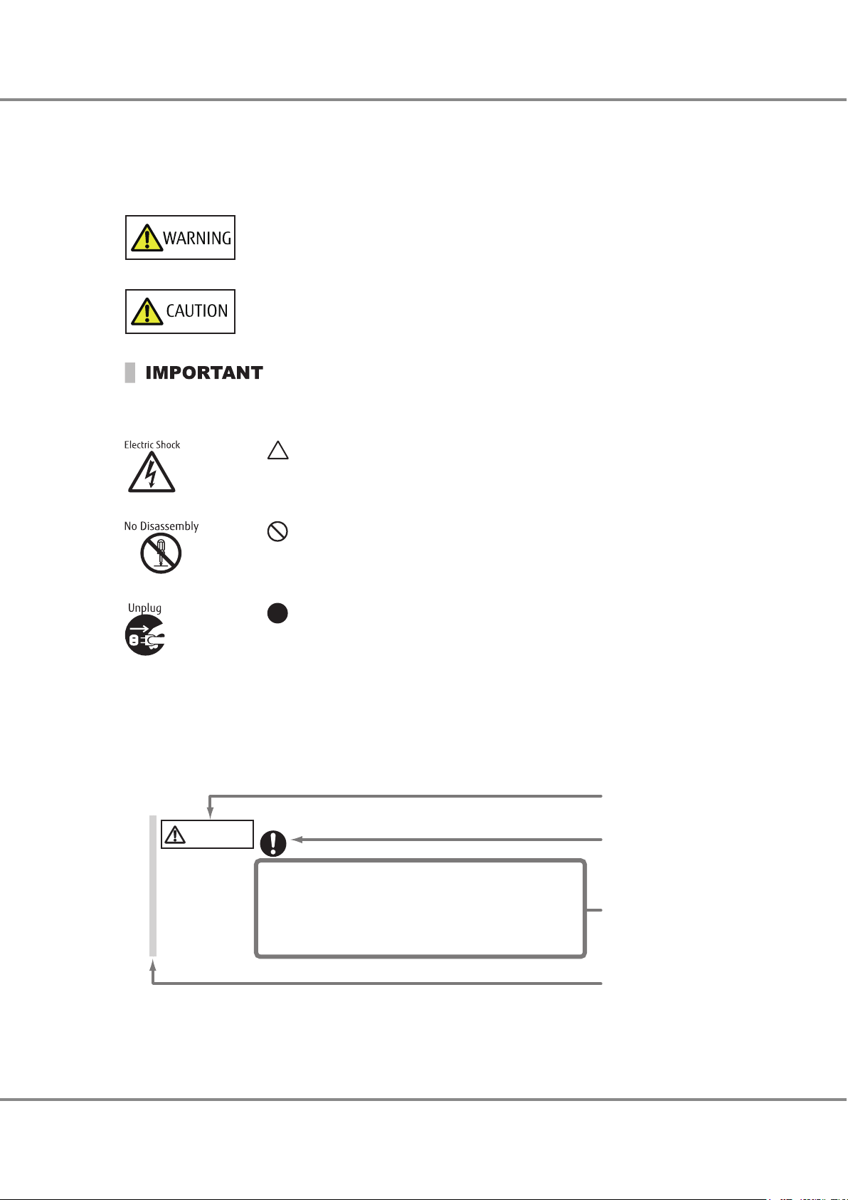
Warning level indicator
Warning type indicator
Warning details
•
To avoid damaging the ETERNUS storage system, pay attention to the
following points when cleaning the ETERNUS storage system:
Warning layout ribbon
Example warning
- Make sure to disconnect the power when cleaning.
- Be car
eful that no liquid seeps into the ETERNUS storage system
when using cleaners, etc.
- Do not use alcohol or other solvents to clean the ETERNUS storage system.
CAUTION
Do
Preface
Warning Signs
Warning signs are shown throughout this manual in order to prevent injury to the user and/or material damage.
These signs are composed of a symbol and a message describing the recommended level of caution. The following explains the symbol, its level of caution, and its meaning as used in this manual.
The following symbols are used to indicate the type of warnings or cautions being described.
This symbol indicates the possibility of serious or fatal injury if the ETERNUS DX is not used
properly.
This symbol indicates the possibility of minor or moderate personal injury, as well as damage to the
ETERNUS DX and/or to other users and their property, if the ETERNUS DX is not
used properly.
This symbol indicates IMPORTANT information for the user to note when using the ETERNUS
DX.
The triangle emphasizes the urgency of the WARNING and CAUTION contents. Inside the
triangle and above it are details concerning the symbol (e.g. Electrical Shock).
The barred "Do Not..." circle warns against certain actions. The action which must be
avoided is both illustrated inside the barred circle and written above it (e.g. No Disassembly).
The black "Must Do..." circle indicates actions that must be taken. The required action is
both illustrated inside the black disk and written above it (e.g. Unplug).
How Warnings are Presented in This Manual
A message is written beside the symbol indicating the caution level. This message is marked with a vertical ribbon in the left margin, to distinguish this warning from ordinary descriptions.
A display example is shown here.
FUJITSU Storage ETERNUS DX500 S4/DX600 S4, ETERNUS DX500 S3/DX600 S3 Hybrid Storage Systems
Copyright 2019 FUJITSU LIMITED
13
Design Guide (Basic)
P3AM-7722-25ENZ0
Page 14

1. Function Overview
The ETERNUS DX provides various functions to ensure data integrity, enhance security, reduce cost, and optimize
the overall performance of the system.
The ETERNUS DX integrates block data (SAN area) and file data (NAS area) in a single device and also provides
advanced functions according to each connection.
These functions enable to respond to problems from various situations.
The ETERNUS DX has functions such as the SAN function (supports block data access), the NAS function (supports
file data access), and basic functions that can be used without needing to recognize the SAN or the NAS connection.
For more details about the basic functions, refer to "2. Basic Functions
functions that are used for a SAN connection, refer to "3. SAN Functions" (page 112).
Table 1 Basic Functions
Overview Function
Data protection
Functions that ensure data integrity to improve data reliability.
It is possible to detect and fix drive failures early.
Resource utilization (virtualization/Automated Storage Tiering)
Functions that deliver effective resource utilization.
Data capacity expansion
•
Functions that expand or relocate a RAID group or a volume
in order to flexibly meet any increases in the amount of data.
Guarantee of performance
•
A function that creates a volume that is striped in multiple
RAID groups in order to improve performance.
Security measures (data encryption)
Functions that encrypt data in the drive media to prevent the
data from being fraudulently decoded.
Security measures (user access management)
Functions to prevent information leakage that are caused by a
malicious access.
Environmental burden reduction
Functions that adjust the operating time and the environment
of the installation location in order to reduce power consumption.
Operation management (device monitoring)
Function that reduce load on the system administrator, and
that improve system stability and increase operating ratio of
the system.
Power control
Power control functions that are used to link power-on and
power-off operations with servers and perform scheduled operations.
" (page 16). For more details about the
"Data Block Guard" (page 31)
"Disk Drive Patrol
"Redundant Copy" (page 34)
"Rebuild" (page 35)
"Fast Recovery" (page 36)
"Copyback/Copybackless" (page 37)
"Protection (Shield)" (page 39)
"Reverse Cabling" (page 41)
"Thin Provisioning" (page 42)
"Flexible Tier
"Extreme Cache" (page 55)
"Extreme Cache Pool" (page 56)
"RAID Migration" (page 59)
"Logical Device Expansion
"LUN Concatenation" (page 62)
"Wide Striping" (page 65)
"Encryption with Self Encrypting Drive (SED)" (page 67)
"Firmware Data Encryption" (page 68)
"Key Management Server Linkage" (page 69)
"Account Management" (page 72)
"User Authentication" (page 74)
"Audit Log" (page 76)
"Eco-mode" (page 77)
"Power Consumption Visualization
"Operation Management Interface" (page 81)
"Performance Information Management
"Event Notification" (page 84)
"Device Time Synchronization" (page 87)
"Power Synchronized Unit" (page 88)
"Remote Power Operation (Wake On LAN)
" (page 33)
" (page 49)
" (page 61)
" (page 80)
" (page 82)
" (page 89)
14
FUJITSU Storage ETERNUS DX500 S4/DX600 S4, ETERNUS DX500 S3/DX600 S3 Hybrid Storage Systems
Copyright 2019 FUJITSU LIMITED
Design Guide (Basic)
P3AM-7722-25ENZ0
Page 15

1. Function Overview
Overview Function
High-speed backup
•
Continuous business
•
Data can be duplicated at any point without affecting other operations.
Performance tuning
A function that can perform tuning in order to improve performance.
Simple configuration
A wizard that simplifies the configuration of Thin Provisioning.
Table 2 SAN Functions
Overview Function
Operations Optimization (Deduplication/Compression)
A function that eliminates duplicated data and compresses the
data to reduce the amount of written data.
Security measures (unauthorized access prevention)
Functions that prevent unintentional storage access.
Stable operation
For stable operation of server connections, the appropriate response action and the processing priority can be specified for
each server.
If an error occurs in the storage system during operations, the
connected storage system is switched automatically and operations can continue.
Data relocation
A function that migrates data between ETERNUS storage systems.
Non-disruptive data relocation
A function that migrates data between ETERNUS storage systems without stopping the business server.
Information linkage (function linkage with servers)
Functions that cooperate with a server to improve performance
in a virtualized environment. Beneficial effects such as centralized management of the entire storage system and a reduction
of the load on servers can be realized.
"Backup (SAN)" (page 91)
"Striping Size Expansion" (page 104)
"Assigned CMs
"Smart Setup Wizard" (page 106)
"Deduplication/Compression" (page 112)
"Host Affinity" (page 120)
"iSCSI Security
"Quality of Service (QoS)" (page 122)
"Host Response" (page
"Storage Cluster" (page 125)
"Storage Migration" (page 128)
"Non-disruptive Storage Migration" (page 130)
"Oracle VM Linkage" (page 132)
"VMware Linkage
"Veeam Storage Integration" (page 138)
"Microsoft Linkage" (page 141)
"OpenStack Linkage" (page 142)
"Logical Volume Manager (LVM)" (page 143)
" (page 105)
" (page 122)
124)
" (page 133)
15
FUJITSU Storage ETERNUS DX500 S4/DX600 S4, ETERNUS DX500 S3/DX600 S3 Hybrid Storage Systems
Copyright 2019 FUJITSU LIMITED
Design Guide (Basic)
P3AM-7722-25ENZ0
Page 16

2. Basic Functions
This chapter describes the functions that control the storage system.
RAID Functions
This section explains the points to note before configuring a system using the ETERNUS DX.
Supported RAID
The ETERNUS DX supports the following RAID levels.
RAID0 (striping)
•
RAID1 (mirroring)
•
RAID1+0 (striping of pairs of drives for mirroring)
•
RAID5 (striping with distributed parity)
•
RAID5+0 (double striping with distributed parity)
•
RAID6 (striping with double distributed parity)
•
RAID6-FR (provides the high speed rebuild function, and striping with double distributed parity)
•
Remember that a RAID0 configuration is not redundant. This means that if a RAID0 drive fails, the data will
not be recoverable.
This section explains the concepts and purposes (RAID level selection criteria) of the supported RAID levels.
When Nearline SAS disks that have 6TB or more are used, the available RAID levels are RAID0, RAID1, RAID6,
and RAID6-FR.
16
FUJITSU Storage ETERNUS DX500 S4/DX600 S4, ETERNUS DX500 S3/DX600 S3 Hybrid Storage Systems
Copyright 2019 FUJITSU LIMITED
Design Guide (Basic)
P3AM-7722-25ENZ0
Page 17

A
C
B
D
Dat
a writing request
Drive#0 Drive#1
A B C D
A
B
C
D
A B C D
Data writing request
A
B
C
D
Drive#0 Drive#1
2. Basic Functions
RAID Functions
■
RAID Level Concept
A description of each RAID level is shown below.
● RAID0 (Striping)
Data is split in unit of blocks and stored across multiple drives.
Figure 1 RAID0 Concept
● RAID1 (Mirroring)
The data is stored on two duplicated drives at the same time.
If one drive fails, other drive continues operation.
Figure 2 RAID1 Concept
FUJITSU Storage ETERNUS DX500 S4/DX600 S4, ETERNUS DX500 S3/DX600 S3 Hybrid Storage Systems
Copyright 2019 FUJITSU LIMITED
17
Design Guide (Basic)
P3AM-7722-25ENZ0
Page 18
Drive#3
Drive#7
D
D'
Drive#2
Drive#6
C
C'
Drive#1
Drive#5
B
B'
D
rive#0
Drive#4
A
A'
Striping (RAID0)
Mir
roring (RAID1)
Data writing request
A B C D
Mirroring
Mirroring
Mirroring
Mirroring
A
E
I
M
A B C D
Data writing request
B
F
J
P M, N, O, P
C
G
P I, J, K, L
N
D
P E, F, G, H
K
O
H
L
P
Create parity data
P A, B, C, D
A B DC
Drive#0 Drive#1 Drive#2 Drive#3 Drive#4
Parity for data A to D: P A, B, C, D
Parity for data E to H: P E, F, G, H
Parity for data I to L: P I, J, K, L
Parity for data M to P: P M, N, O, P
2. Basic Functions
RAID Functions
● RAID1+0 (Striping of Pairs of Drives for Mirroring)
RAID1+0 combines the high I/O performance of RAID0 (striping) with the reliability of RAID1 (mirroring).
Figure 3 RAID1+0 Concept
● RAID5 (Striping with Distributed Parity)
Data is divided into blocks and allocated across multiple drives together with parity information created from
the data in order to ensure the redundancy of the data.
Figure 4 RAID5 Concept
Copyright 2019 FUJITSU LIMITED
FUJITSU Storage ETERNUS DX500 S4/DX600 S4, ETERNUS DX500 S3/DX600 S3 Hybrid Storage Systems
18
Design Guide (Basic)
P3AM-7722-25ENZ0
Page 19
Striping with
dis
tributed parity (RAID5)
Striping (RAID0)
A
E
B
I
F
P A, B
P M, N
C
G H
P C, D
P O, P
Drive#0 Drive#1 Drive#2 Drive#3 Drive#4 Drive#5
D
K
P K, L
Striping (RAID0)
Striping with
distributed parity
(RAID5)
J
L
M
N
O
P
P E, F
P I, J
P G, H
RAID5 RAID5
A B
Create parity data
D
Create parity data
C
Data writing request
A
B
C
D
A B C D
A B C D
2. Basic Functions
RAID Functions
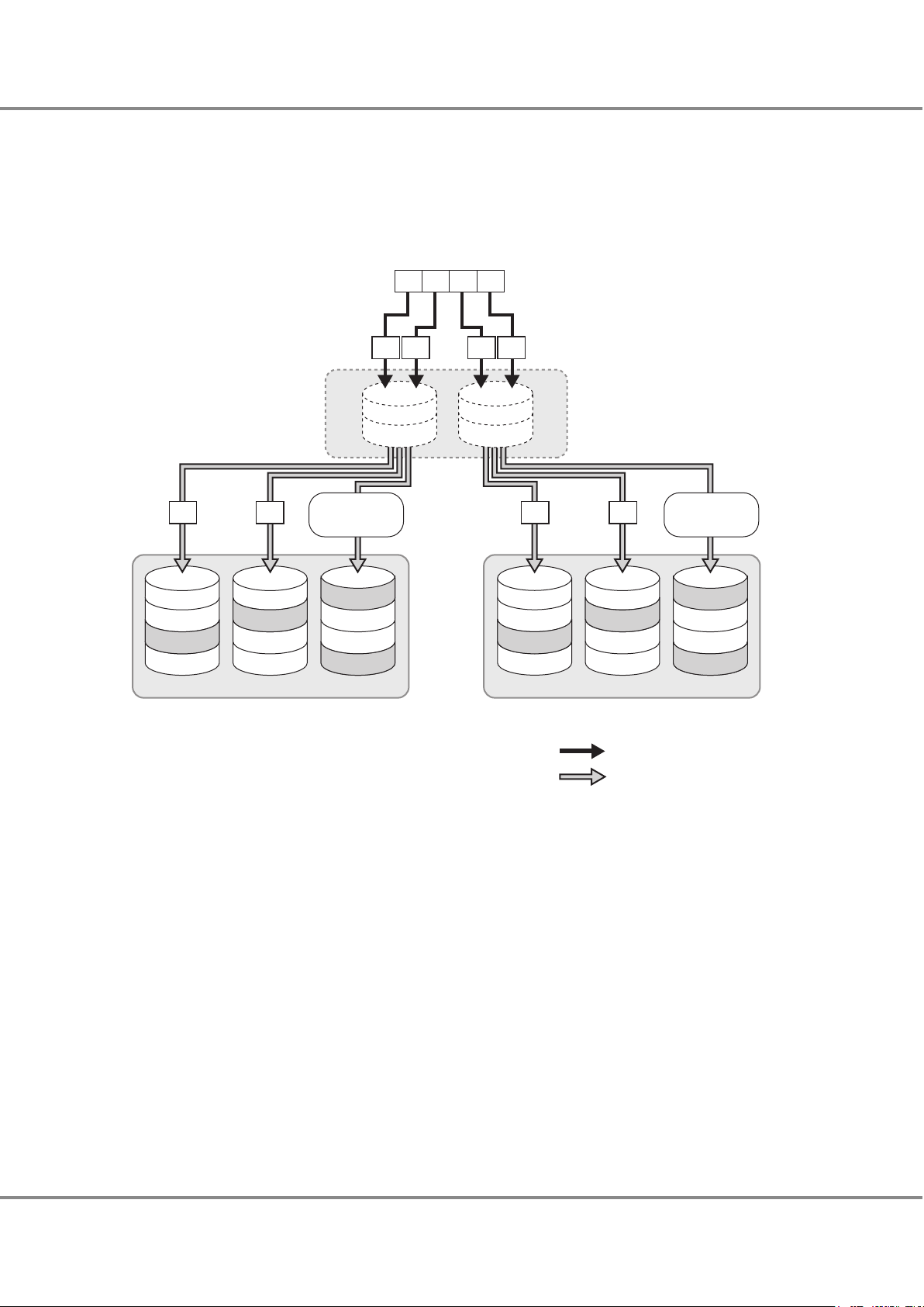
● RAID5+0 (Double Striping with Distributed Parity)
Multiple RAID5 volumes are RAID0 striped. For large capacity configurations, RAID5+0 provides better performance, better reliability, and shorter rebuilding times than RAID5.
Figure 5 RAID5+0 Concept
FUJITSU Storage ETERNUS DX500 S4/DX600 S4, ETERNUS DX500 S3/DX600 S3 Hybrid Storage Systems
Copyright 2019 FUJITSU LIMITED
19
Design Guide (Basic)
P3AM-7722-25ENZ0
Page 20
P2 M, N
, O, P
P2 I, J, K, L
A
E
I
M
A
B C D
Data writing request
B
F
J
P1 M, N, O, P
C
G
P1 I, J, K, L
D
P1 E, F, G, H P2 E, F
, G, H
N
K
O
P1
A, B, C, D
H
L
P
P2
A, B, C, D
A B DC
Create parity data
Drive#0 Drive#1 Drive#2 Drive#3 Drive#4 Drive#5
Parity for data A to D: P1 A, B, C, D and P2 A, B, C, D
Parity for data E to H: P1 E, F, G, H and P2 E, F, G, H
Parity for data I to L: P1 I, J, K, L and P2 I, J, K, L
Parity for data M to P: P1 M, N, O, P and P2 M, N, O, P
2. Basic Functions
RAID Functions
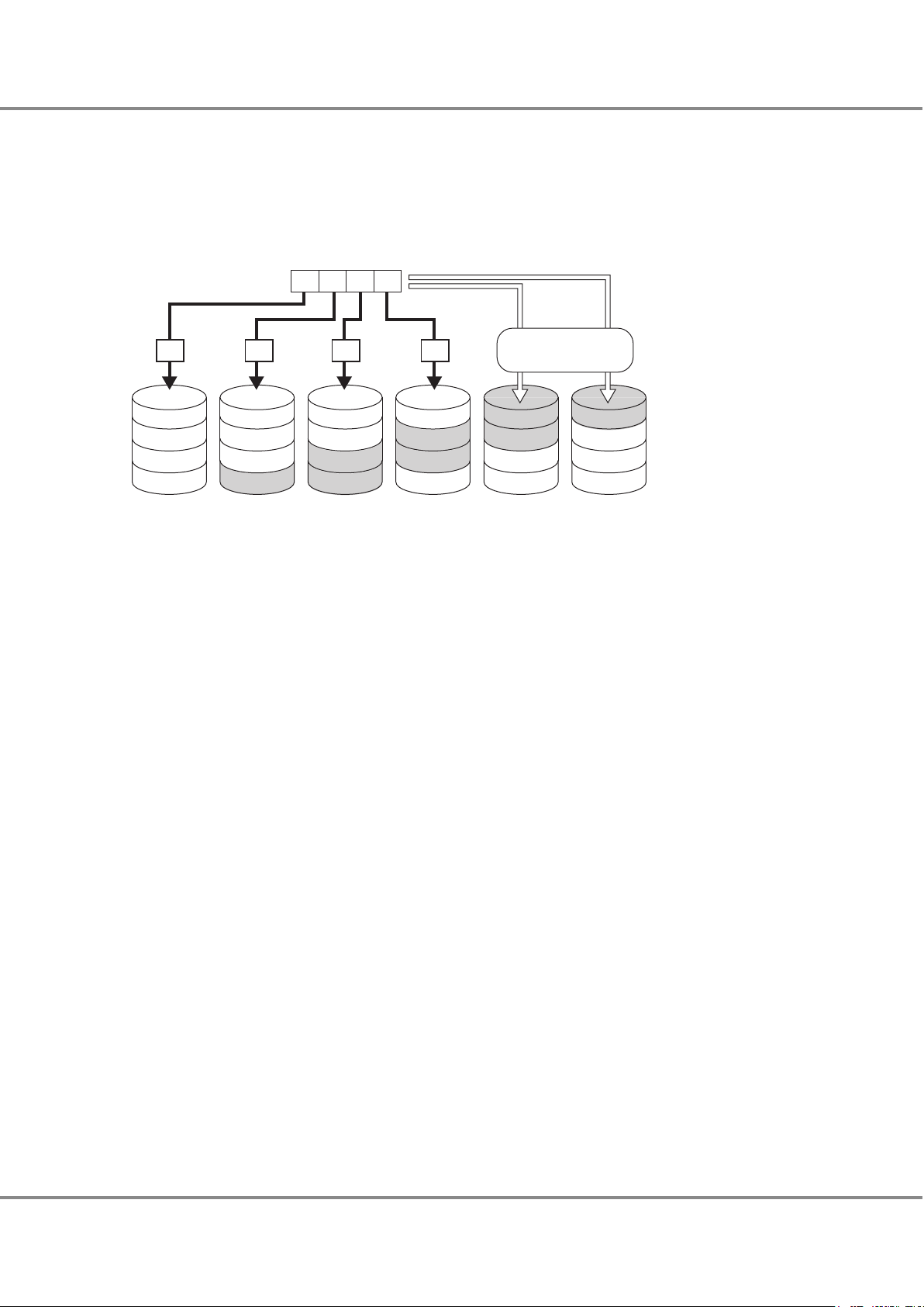
● RAID6 (Striping with Double Distributed Parity)
Allocating two different parities on different drives (double parity) makes it possible to recover from up to two
drive failures.
Figure 6 RAID6 Concept
FUJITSU Storage ETERNUS DX500 S4/DX600 S4, ETERNUS DX500 S3/DX600 S3 Hybrid Storage Systems
Copyright 2019 FUJITSU LIMITED
20
Design Guide (Basic)
P3AM-7722-25ENZ0
Page 21
RAID6-FR ((3D+2P) × 2 + 1HS)
H
FHS
V
E
I
S
C
J
A
K
FHS
X W
F
FHS
N
T
G
Q
U
D
O
FHS
B
R
FHS
P
FHS
M
L
A B C D
Data writing request
A B C D
Create parity data Create parity data
P1 A, B, C
P1 P, Q, RP2 P, Q, R
P1 V, W, X
P1 M, N, O
P2 M, N, O
P1 D, E, F
P2 J, K, L
P2 D, E, F
P1 J, K, L
P1 S, T, U
P2 G, H, I P1 G, H, I
P2 S, T, U
P2 A, B, C
P2 V, W, X
Drive#0 Drive#1 Drive#2 Drive#3 Drive#4 Drive#5 Drive#6 Drive#7 Drive#8 Drive#9 Drive#10
Parity for data A, B, C: P1 A, B, C and P2 A, B, C
Parity for data D, E, F: P1 D, E, F and P2 D, E, F
Parity for data G, H, I: P1 G, H, I and P2 G, H, I
Parity for data J, K, L: P1 J, K, L and P2 J, K, L
Parity for data M, N, O: P1 M, N, O and P2 M, N, O
Parity for data P, Q, R: P1 P, Q, R and P2 P, Q, R
Parity for data S, T, U: P1 S, T, U and P2 S, T, U
Parity for data V, W, X: P1 V, W, X and P2 V, W, X
:
Fast recovery Hot Spare: FHS
2. Basic Functions
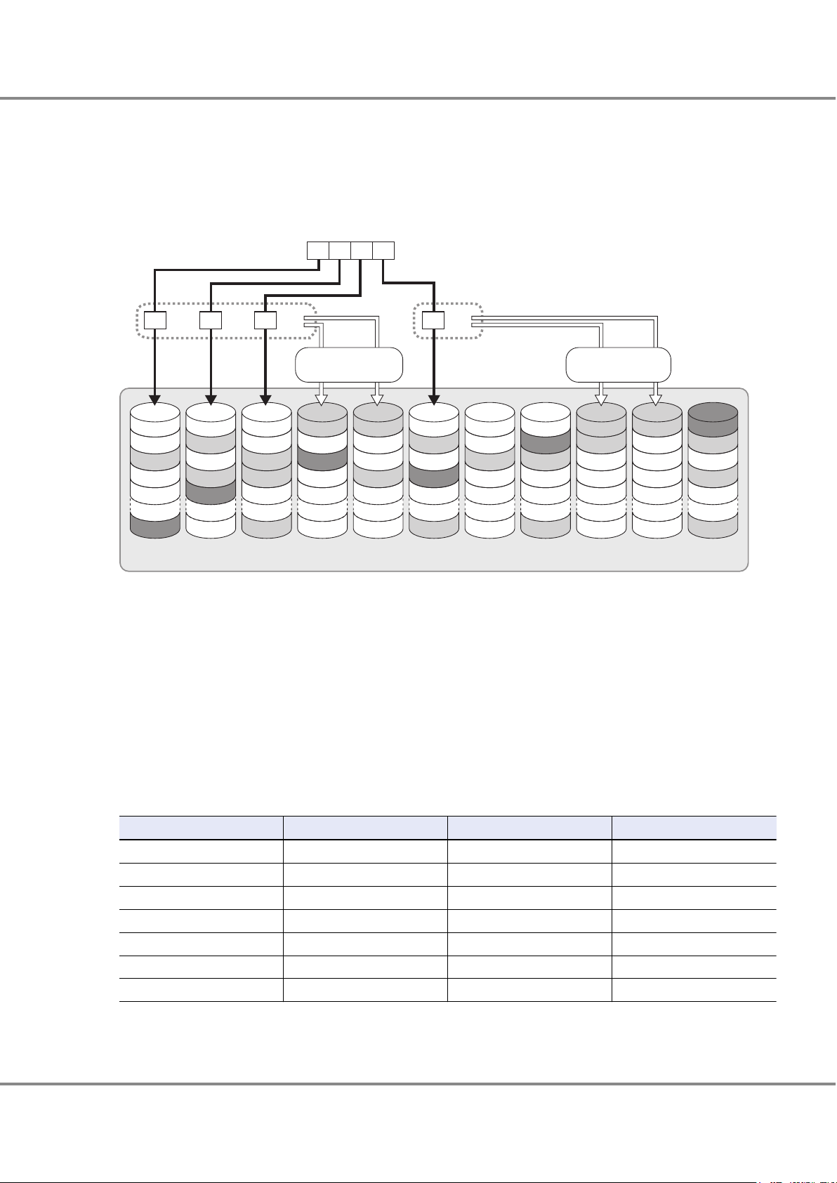
RAID Functions
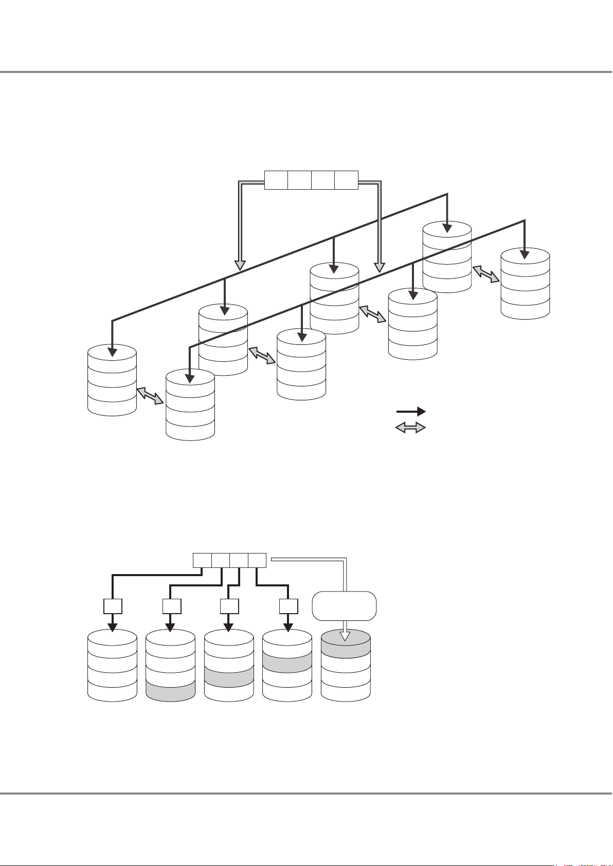
● RAID6-FR (Provides the High Speed Rebuild Function, and Striping with Double Distributed Parity)
Distributing multiple data groups and reserved space equivalent to hot spares to the configuration drives makes
it possible to recover from up to two drive failures. RAID6-FR requires less build time than RAID6.
Figure 7 RAID6-FR Concept
■
Reliability, Performance, Capacity for Each RAID Level
Table 3 shows the comparison result of reliability, performance, capacity for each RAID level.
Table 3 RAID Level Comparison
RAID level Reliability Performance (*1) Capacity
RAID0
RAID1
RAID1+0
RAID5
RAID5+0
RAID6 ◎
RAID6-FR ◎
´
◎ ◎
¡ ¡
¡
¡ ¡ ¡
¡ ¡ ¡
◎ △
¡ ¡
¡ ¡
◎: Very good ¡: Good △: Reasonable ´: Poor
*1: Performance may differ according to the number of drives and the processing method from the host.
FUJITSU Storage ETERNUS DX500 S4/DX600 S4, ETERNUS DX500 S3/DX600 S3 Hybrid Storage Systems
Copyright 2019 FUJITSU LIMITED
21
Design Guide (Basic)
△
P3AM-7722-25ENZ0
Page 22

2. Basic Functions
RAID Functions
■
Recommended RAID Level
Select the appropriate RAID level according to the usage.
Recommended RAID levels are RAID1, RAID1+0, RAID5, RAID5+0, RAID6, and RAID6-FR.
•
When importance is placed upon read and write performance, a RAID1+0 configuration is recommended.
•
For read only file servers and backup servers, RAID5, RAID5+0, RAID6, or RAID6-FR can also be used for higher
•
efficiency. However, if the drive fails, note that data restoration from parities and rebuilding process may result in a loss in performance.
For SSDs, a RAID5 configuration or a fault tolerant enhanced RAID6 configuration is recommended because
•
SSDs operate much faster than other types of drive. For large capacity SSDs, using a RAID6-FR configuration,
which provides excellent performance for the rebuild process, is recommended.
Using a RAID6 or RAID6-FR configuration is recommended when Nearline SAS disks that have 6TB or more are
•
used. For details on the RAID levels that can be configured with Nearline SAS disks that have 6TB or more,
refer to "
Supported RAID" (page 16).
User Capacity (Logical Capacity)
User Capacity for Each RAID Level
The user capacity depends on the capacity of drives that configure a RAID group and the RAID level.
Table 4 shows the formula for calculating the user capacity for each RAID level.
Table 4 Formula for Calculating User Capacity for Each RAID Level
RAID level Formula for user capacity computation
RAID0
RAID1
RAID1+0
RAID5
RAID5+0
RAID6
RAID6-FR
*1: "N" is the number of RAID6 configuration sets. For example, if a RAID6 group is configured with "(3D+2P)
´2+1HS", N is "2".
Drive capacity ´ Number of drives
Drive capacity ´ Number of drives ¸ 2
Drive capacity ´ Number of drives ¸ 2
Drive capacity ´ (Number of drives - 1)
Drive capacity ´ (Number of drives - 2)
Drive capacity ´ (Number of drives - 2)
Drive capacity ´ (Number of drives - (2 ´ N) - Number of hot spares) (*1)
22
FUJITSU Storage ETERNUS DX500 S4/DX600 S4, ETERNUS DX500 S3/DX600 S3 Hybrid Storage Systems
Copyright 2019 FUJITSU LIMITED
Design Guide (Basic)
P3AM-7722-25ENZ0
Page 23

2. Basic Functions
RAID Functions
User Capacity of Drives
Table 5
shows the user capacity for each drive.
The supported drives vary between the ETERNUS DX500 S4/DX600 S4 and the ETERNUS DX500 S3/DX600 S3. For
details about drives, refer to "Overview" of the currently used storage systems.
Table 5 User Capacity per Drive
Product name (*1) User capacity
400GB SSD 374,528MB
800GB SSD 750,080MB
960GB SSD 914,432MB
1.6TB SSD 1,501,440MB
1.92TB SSD 1,830,144MB
3.84TB SSD 3,661,568MB
7.68TB SSD 7,324,416MB
15.36TB SSD 14,650,112MB
30.72TB SSD 29,301,504MB
300GB SAS disk 279,040MB
600GB SAS disk 559,104MB
900GB SAS disk 839,168MB
1.2TB SAS disk 1,119,232MB
1.8TB SAS disk 1,679,360MB
2.4TB SAS disk 2,239,744MB
1TB Nearline SAS disk 937,728MB
2TB Nearline SAS disk 1,866,240MB
3TB Nearline SAS disk 2,799,872MB
4TB Nearline SAS disk 3,733,504MB
6TB Nearline SAS disk (*2) 5,601,024MB
8TB Nearline SAS disk (*2) 7,468,288MB
10TB Nearline SAS disk (*2) 9,341,696MB
12TB Nearline SAS disk (*2) 11,210,496MB
14TB Nearline SAS disk (*2) 13,079,296MB
*1: The capacity of the product names for the drives is based on the assumption that 1MB = 1,0002 bytes,
while the user capacity for each drive is based on the assumption that 1MB = 1,0242 bytes. Furthermore,
OS file management overhead will reduce the actual usable capacity.
The user capacity is constant regardless of the drive size (2.5"/3.5"), the SSD type (Value SSD and MLC SSD),
or the encryption support (SED).
*2: For details on the RAID levels that can be configured with Nearline SAS disks that have 6TB or more, refer
Supported RAID" (page 16).
to "
23
FUJITSU Storage ETERNUS DX500 S4/DX600 S4, ETERNUS DX500 S3/DX600 S3 Hybrid Storage Systems
Copyright 2019 FUJITSU LIMITED
Design Guide (Basic)
P3AM-7722-25ENZ0
Page 24

2. Basic Functions
RAID Functions
RAID Group
This section explains RAID groups.
A RAID group is a group of drives. It is a unit that configures RAID. Multiple RAID groups with the same RAID
level or multiple RAID groups with different RAID levels can be set together in the
group is created, RAID levels can be changed and drives can be added.
Table 6 RAID Group Types and Usage
ETERNUS DX. After a RAID
Type Usage
RAID group Areas to store normal data. Volumes (Standard, WSV,
SDV, SDPV) for work and Advanced Copy can be created
in a RAID group.
REC Disk Buffer Areas that are dedicated for the REC Consistency mode to
temporarily back up copy data.
Thin Provisioning
Pool (TPP) (*5)
Flexible Tier Sub
Pool (FTSP) (*6)
RAID groups that are used for Thin Provisioning in which
the areas are managed as a Thin Provisioning Pool (TPP).
Thin Provisioning Volumes (TPVs) can be created in a
TPP.
RAID groups that are used for the Flexible Tier function in
which the areas are managed as a Flexible Tier Sub Pool
(FTSP). Larger pools (Flexible Tier Pools: FTRPs) are comprised by layers of FTSPs. Flexible Tier Volumes (FTVs) can
be created in an FTSP.
*1: This value is for a 15.36TB SSD RAID6-FR ([13D+2P]´2+1HS) configuration in the
Maximum capacity
Per RAID group Per storage system
Approximately 363TB
(*1)
Approximately 726TB
(*2)
Approximately 55TB
(*3)
Approximately 111TB
(*4)
3,072TB (ETERNUS DX500 S4/DX500 S3) (*7)
8,192TB (ETERNUS DX600 S4/DX600 S3
Depends on the number
of installable drives
110TB (*3)
222TB (*4)
) (*7)
ETERNUS DX500 S3/DX600
S3.
For details on the number of configuration drives for each RAID level and recommended configurations,
refer to Table 7.
*2: This value is for a 30.72TB SSD RAID6-FR ([13D+2P]´2+1HS) configuration in the
ETERNUS DX500 S4/DX600
S4.
For details on the number of configuration drives for each RAID level and recommended configurations,
refer to Table 7.
*3: This value is for a 15.36TB SSD RAID1+0 (4D+4M) configuration in the ETERNUS DX500 S3/DX600 S3.
*4: This value is for a 30.72TB SSD RAID1+0 (4D+4M) configuration in the ETERNUS DX500 S4/DX600 S4.
*5: For details on the number of configuration drives for each RAID level and recommended configurations,
refer to Table 14.
*6: For details on the number of configuration drives for each RAID level and recommended configurations,
refer to Table 19.
*7: Total of the Thin Provisioning Pool capacity and the FTSP capacity.
24
FUJITSU Storage ETERNUS DX500 S4/DX600 S4, ETERNUS DX500 S3/DX600 S3 Hybrid Storage Systems
Copyright 2019 FUJITSU LIMITED
Design Guide (Basic)
P3AM-7722-25ENZ0
Page 25
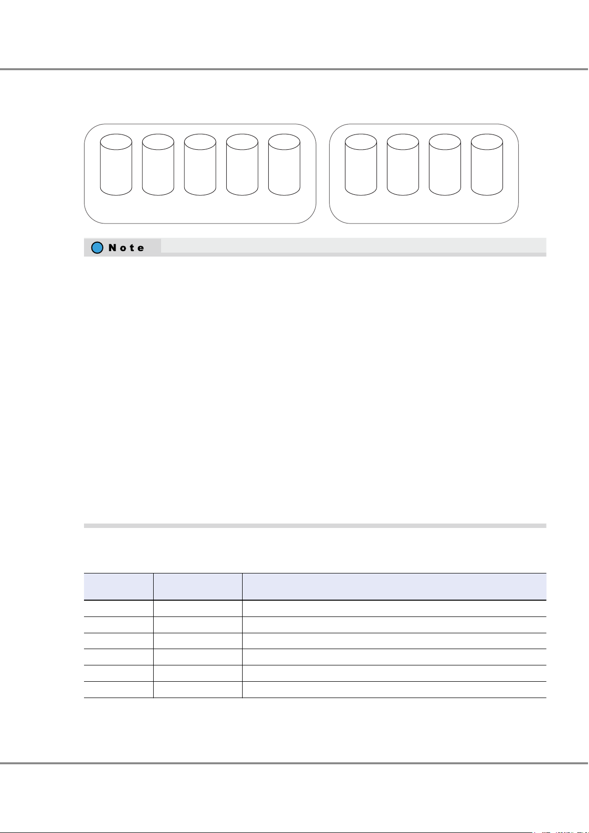
RAID group 1 RAID group 2
SAS
600GB
S
AS
600GB
SAS
600GB
SAS
600GB
SAS
600GB
SSD
400GB
SSD
400GB
SSD
400GB
SSD
400GB
2. Basic Functions
RAID Functions
The same size drives (2.5", 3.5") and the same kind of drives (SAS disks, Nearline SAS disks, SSDs, or SEDs) must
be used to configure a RAID group.
Figure 8 Example of a RAID Group
SAS disks and Nearline SAS disks can be installed together in the same group. Note that SAS disks and Near-
•
line SAS disks cannot be installed with SSDs or SEDs.
Use drives that have the same size, capacity, rotational speed (for disks), Advanced Format support, inter-
•
face speed (for SSDs), and drive enclosure transfer speed (for SSDs) to configure RAID groups.
-
-
-
-
-
For details on the RAID levels that can be configured with Nearline SAS disks that have 6TB or more, refer to
•
"Supported RAID
If a RAID group is configured with drives that have different capacities, all the drives in the RAID group are
recognized as having the same capacity as the drive with the smallest capacity in the RAID group and the
rest of the capacity in the drives that have a larger capacity cannot be used.
If a RAID group is configured with drives that have different rotational speeds, the performance of all of
the drives in the RAID group is reduced to that of the drive with the lowest rotational speed.
If a RAID group is configured with SSDs that have different interface speeds, the performance of all of the
SSDs in the RAID group is reduced to that of the SSD with the lowest interface speed.
3.5" SAS disks are handled as being the same size type as the drives for high-density drive enclosures. For
example, 3.5" Nearline SAS disks and Nearline SAS disks for high-density drive enclosures can exist together in the same RAID group.
When a RAID group is configured with SSDs in both the high-density drive enclosure (6Gbit/s), and the
3.5" type drive enclosure or the high-density drive enclosure (12Gbit/s), because the interface speed of
the high-density drive enclosure (6Gbit/s) is 6Gbit/s, all of the SSDs in the RAID group operate at 6Gbit/s.
" (page 16).
Table 7 shows the recommended number of drives that configure a RAID group.
Table 7 Recommended Number of Drives per RAID Group
RAID level
RAID1 2 2(1D+1M)
RAID1+0 4 to 32 4(2D+2M), 6(3D+3M), 8(4D+4M), 10(5D+5M)
RAID5 3 to 16 3(2D+1P), 4(3D+1P), 5(4D+1P), 6(5D+1P)
RAID5+0 6 to 32
RAID6 5 to 16 5(3D+2P), 6(4D+2P), 7(5D+2P)
RAID6-FR 11 to 31
Number of configuration drives
Recommended number of drives (*1)
3(2D+1P) ´ 2,
17 ((6D+2P) ´2+1HS)
4(3D+1P) ´ 2, 5(4D+1P) ´ 2, 6(5D+1P) ´ 2
*1: D = Data, M = Mirror, P = Parity, HS = Hot Spare
FUJITSU Storage ETERNUS DX500 S4/DX600 S4, ETERNUS DX500 S3/DX600 S3 Hybrid Storage Systems
25
Copyright 2019 FUJITSU LIMITED
Design Guide (Basic)
P3AM-7722-25ENZ0
Page 26
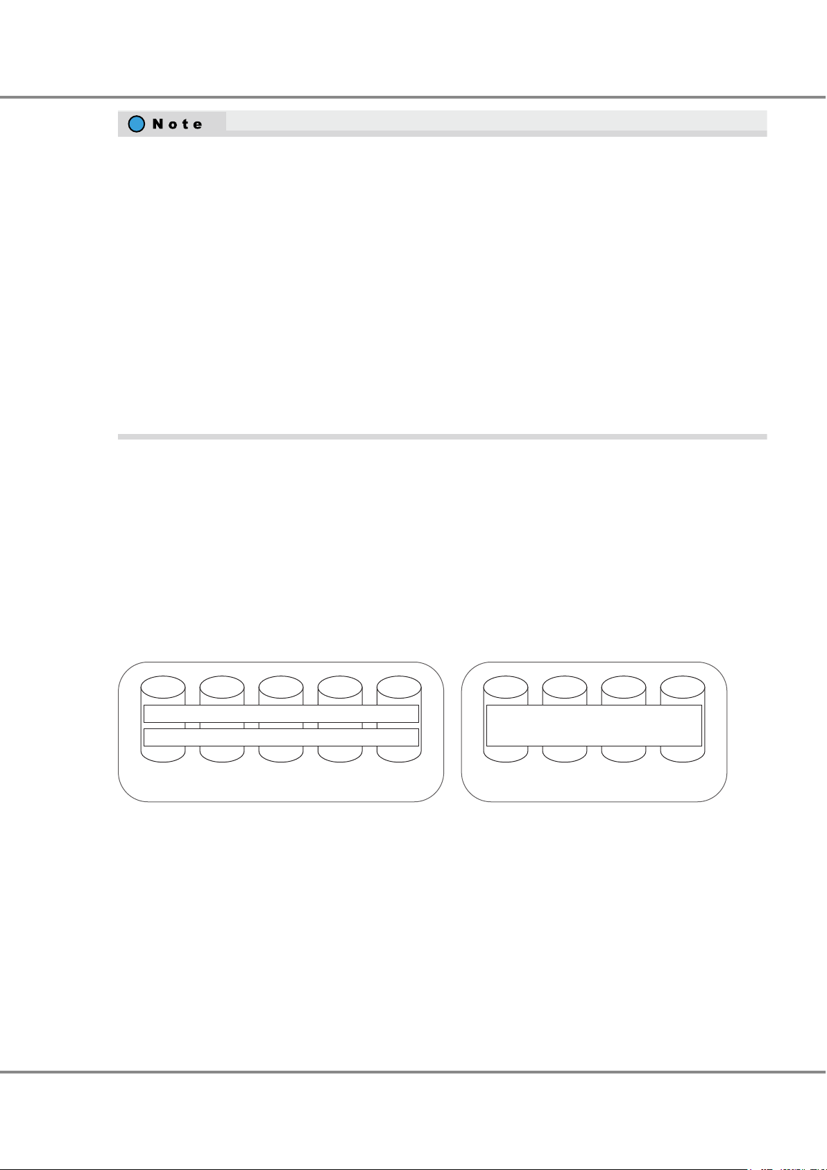
RAID group 1 RAID group 2
Volume 1
Volume 2
Volume 3
2. Basic Functions
RAID Functions
Sequential access performance hardly varies with the number of drives for the RAID group.
•
Random access performance tends to be proportional to the number of drives for the RAID group.
•
Use of higher capacity drives will increase the time required for the drive rebuild process to complete.
•
For RAID5, RAID5+0, and RAID6, ensure that a single RAID group is not being configured with too many
•
drives.
If the number of drives increases, the time to perform data restoration from parities and Rebuild/Copyback
when a drive fails also increases.
For details on the recommended number of drives, refer to Table 7.
The RAID level that can be registered in REC Disk Buffers is RAID1+0. The drive configurations that can be
•
registered in REC Disk Buffers is 2D+2M or 4D+4M.
For details on the Thin Provisioning function and the RAID configurations that can be registered in Thin Pro-
visioning Pools, refer to "Storage Capacity Virtualization" (page 43
For details on the Flexible Tier functions and the RAID configurations that can be registered in Flexible Tier
Pools, refer to "Automated Storage Tiering" (page 49).
).
Volume
An assigned CM is allocated to each RAID group. For details, refer to "
Assigned CMs" (page 105).
For the installation locations of the drives that configure the RAID group, refer to "Recommended RAID Group
Configuration" (page 200).
This section explains volumes.
Logical drive areas in RAID groups are called volumes.
A volume is the basic RAID unit that can be recognized by the server.
Figure 9 Volume Concept
A volume may be up to 128TB. However, the maximum capacity of volume varies depending on the OS of the
server.
The maximum number of volumes that can be created in the
ETERNUS DX is 16,384. Volumes can be created
until the combined total for each volume type reaches the maximum number of volumes.
A volume can be expanded or moved if required. Multiple volumes can be concatenated and treated as a single
volume. For availability of expansion, displacement, and concatenation for each volume, refer to "Target Vol-
umes of Each Function" (page 212).
FUJITSU Storage ETERNUS DX500 S4/DX600 S4, ETERNUS DX500 S3/DX600 S3 Hybrid Storage Systems
Copyright 2019 FUJITSU LIMITED
26
Design Guide (Basic)
P3AM-7722-25ENZ0
Page 27

2. Basic Functions
RAID Functions
The types of volumes that are listed in the table below can be created in the ETERNUS DX.
Table 8 Volumes That Can Be Created
Type Usage Maximum capacity
Standard (Open) A standard volume is used for normal usage, such as file sys-
Snap Data Volume (SDV) This area is used as the copy destination for SnapOPC/
Snap Data Pool Volume (SDPV) This volume is used to configure the Snap Data Pool (SDP)
Thin Provisioning Volume (TPV) This virtual volume is created in a Thin Provisioning Pool area. 128TB
Flexible Tier Volume (FTV) This volume is a target volume for layering. Data is automati-
Virtual Volumes (VVOLs) A VVOL is a VMware vSphere dedicated capacity virtualization
Deduplication/Compression Volume This volume is a virtual volume that is recognized by the serv-
Wide Striping Volume (WSV) This volume is created by concatenating distributed areas in
ODX Buffer volume An ODX Buffer volume is a dedicated volume that is required
tems and databases. The server recognizes it as a single logical unit.
"Standard" is displayed as the type for this volume in ETERNUS
Web GUI/ETERNUS CLI and "Open" is displayed in ETERNUS SF
software.
SnapOPC+. There is a SDV for each copy destination.
area. The SDP capacity equals the total capacity of the SDPVs.
A volume is supplied from a SDP when the amount of updates
exceeds the capacity of the copy destination SDV.
cally redistributed in small block units according to the access
frequency. An FTV belongs to a Flexible Tier Pool.
volume. Operations can be simplified by associating VVOLs
with virtual disks.
Its volume type is FTV.
er when the Deduplication/Compression function is used. It
can be created by enabling the Deduplication/Compression
setting for a volume that is to be created. The data is seen by
the server as being non-deduplicated and uncompressed.
The volume type is TPV.
from 2 to 64 RAID groups. Processing speed is fast because
data access is distributed.
to use the Offloaded Data Transfer (ODX) function of Windows
Server 2012 or later. It is used to save the source data when
data is updated while a copy is being processed.
It can be created one per ETERNUS DX.
Its volume type is Standard, TPV, or FTV.
128TB (*1)
24 [MB] + copy source
volume capacity ´ 0.1 [%]
(*2)
2TB
128TB
128TB
128TB
128TB
1TB
*1: When multiple volumes are concatenated using the LUN Concatenation function, the maximum capacity is
also
128TB.
*2: The capacity differs depending on the copy source volume capacity.
After a volume is created, formatting automatically starts. A server can access the volume while it is being for-
matted. Wait for the format to complete if high performance access is required for the volume.
27
FUJITSU Storage ETERNUS DX500 S4/DX600 S4, ETERNUS DX500 S3/DX600 S3 Hybrid Storage Systems
Copyright 2019 FUJITSU LIMITED
Design Guide (Basic)
P3AM-7722-25ENZ0
Page 28
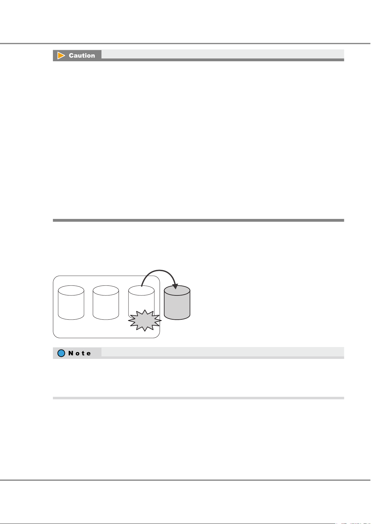
Hot spare
Failure
RAID group
2. Basic Functions
RAID Functions
In the ETERNUS DX
•
parameter.
For details about the stripe sizes for each RAID level and the stripe depth parameter values, refer to "ETER-
NUS Web GUI User's Guide".
Note that the available user capacity can be fully utilized if an exact multiple of the stripe size is set for the
volume size. If an exact multiple of the stripe size is not set for the volume size, the capacity is not fully
utilized and some areas remain unused.
When a Thin Provisioning Pool (TPP) is created, a control volume is created for each RAID group that config-
•
ures the relevant TPP. Therefore, the maximum number of volumes that can be created in the ETERNUS DX
decreases by the number of RAID groups that configure a TPP.
When the Flexible Tier function is enabled, 64 work volumes are created. The maximum number of volumes
•
that can be created in the ETERNUS DX decreases by the number of work volumes that are created.
When a Flexible Tier Sub Pool (FTSP) is created, a control volume is created for each RAID group that config-
•
ures the relevant FTSP. Therefore, the maximum number of volumes that can be created in the ETERNUS DX
decreases by the number of RAID groups that configure an FTSP.
When using the VVOL function, a single volume for the VVOL management information is created the mo-
•
ment a VVOL is created. The maximum number of volumes that can be created in the ETERNUS DX decreases by the number of volumes for the VVOL management information that are created.
Hot Spares
, volumes have different stripe sizes that depend on the RAID level and the stripe depth
Hot spares are used as spare drives for when drives in a RAID group fail, or when drives are in error status.
Figure 10 Hot Spares
When the RAID level is RAID6-FR, data in a failed drive can be restored to a reserved space in a RAID group
even when a drive error occurs because a RAID6-FR RAID group retains a reserved space for a whole drive in
the RAID group. If the reserved area is in use and an error occurs in another drive (2nd) in the RAID group,
then the hot spare is used as a spare.
■
Types of Hot Spares
The following two types of hot spare are available:
Global Hot Spare
•
This is available for any RAID group. When multiple hot spares are installed, the most appropriate drive is automatically selected and incorporated into a RAID group.
FUJITSU Storage ETERNUS DX500 S4/DX600 S4, ETERNUS DX500 S3/DX600 S3 Hybrid Storage Systems
Copyright 2019 FUJITSU LIMITED
28
Design Guide (Basic)
P3AM-7722-25ENZ0
Page 29
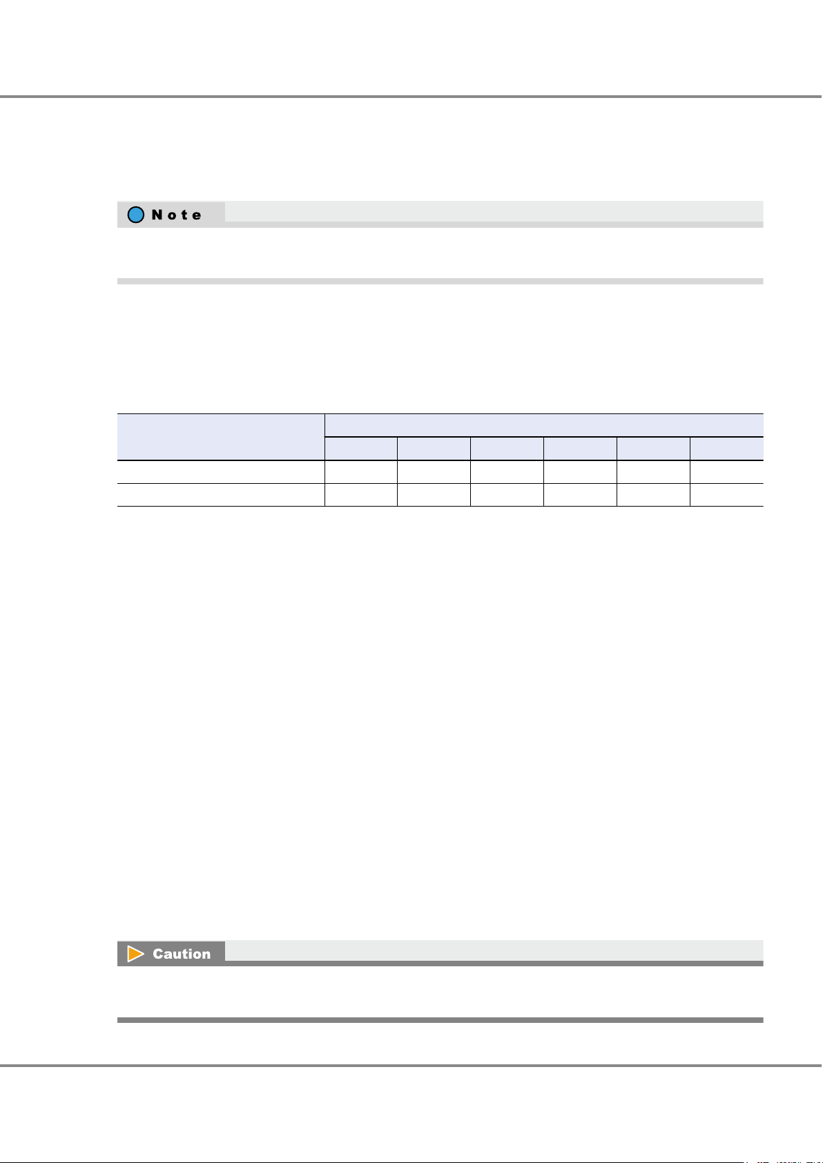
2. Basic Functions
RAID Functions
Dedicated Hot Spare
•
This is only available to the specified RAID group (one RAID group).
The Dedicated Hot Spare cannot be registered in a RAID group that is registered in TPPs, FTRPs, or REC Disk
Buffers.
Assign "Dedicated Hot Spares" to RAID groups that contain important data, in order to preferentially improve
their access to hot spares.
■
Number of Installable Hot Spares
The number of required hot spares is determined by the total number of drives.
The following table shows the recommended number of hot spares for each drive type.
Table 9 Hot Spare Installation Conditions
Model
ETERNUS DX500 S4/DX500 S3 1 2 4 6 — —
ETERNUS DX600 S4/DX600 S3 1 2 4 6 8 9
■
Types of Drives
If a combination of SAS disks, Nearline SAS disks, SSDs, and SEDs is installed in the ETERNUS DX, each different
type of drive requires a corresponding hot spare.
2.5" and 3.5" drive types are available. The drive type for high-density drive enclosures is 3.5".
There are two types of rotational speeds for SAS disks; 10,000rpm and 15,000rpm. If a drive error occurs and a
hot spare is configured in a RAID group with different rotational speed drives, the performance of all the drives
in the RAID group is determined by the drive with the slowest rotational speed. When using SAS disks with different rotational speeds, prepare hot spares that correspond to the different rotational speed drives if required.
Even if a RAID group is configured with SAS disks that have different interface speeds, performance is not affected.
There are two types of interface speeds for SSDs; 6Gbit/s and 12Gbit/s. If a drive error occurs and a hot spare is
configured in a RAID group with different interface speed SSDs, the performance of all the SSDs in the RAID
group is determined by the SSDs with the slowest interface speed. Preparing SSDs with the same interface speed
as the hot spare is recommended.
The capacity of each hot spare must be equal to the largest capacity of the same-type drives.
Total number of drives
Up to 120 Up to 240 Up to 480 Up to 720 Up to 960 Up to 1056
■
Selection Criteria
When multiple Global Hot Spares are installed, among the drives that match the selection criteria in the order of
priority for Condition 1, drives that match the selection criteria in the order of priority for Condition 2 are automatically selected as a hot spare to replace the failed drive.
If different drive types or capacities are mixed, the recommended action is to install a hot spare for each different drive type or capacity on each path.
29
FUJITSU Storage ETERNUS DX500 S4/DX600 S4, ETERNUS DX500 S3/DX600 S3 Hybrid Storage Systems
Copyright 2019 FUJITSU LIMITED
Design Guide (Basic)
P3AM-7722-25ENZ0
Page 30
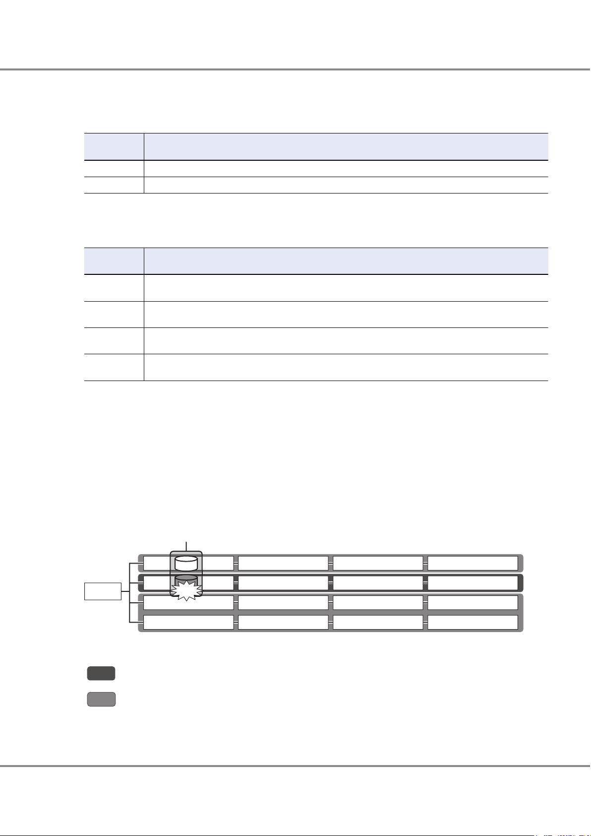
DE#00
5
DE#01
6
DE#02
7
DE#03
8
DE#10
1
DE#11
2
DE#12
3
DE#13
4
DE#20
9
DE#21
1
0
DE#22
1
1
DE#23
1
2
DE#30
1
3
DE#31
1
4
DE#32
1
5
DE#33
1
5
CE
RAID group
Failure
2. Basic Functions
RAID Functions
● Condition 1
Table 10 Hot Spare Selection Criteria (Condition 1)
Selection order
1 A drive enclosure that is located in the same path as the failed drive
2 A drive enclosure that is not located in the same path as the failed drive
Selection criteria
● Condition 2
Table 11 Hot Spare Selection Criteria (Condition 2)
Selection order
1 A hot spare with the same type, same capacity, and same rotational speed (for disks) or same interface speed
2 A hot spare with the same type, and same rotational speed (for disks) or same interface speed (for SSDs) as the
3 A hot spare with the same type and same capacity as the failed drive but with a different rotational speed (for
4 A hot spare with the same type as the failed drive but with a larger capacity and a different rotational speed (for
*1: If multiple drives are applicable, priority is given to the drives in ascending order of the enclosure number
and the drive slot number.
*2: When there are multiple hot spares with a larger capacity than the failed drive, the hot spare with the
smallest capacity among them is used first.
The figure below shows an example of a drive search order when a drive failure occurs.
First, drives are selected in the order of priority (1 to 4) for Condition 2 among the drives in the drive enclosures
that are located in the same path as the failed drive. If there are no applicable drives in the same path, drives
that match Condition 2 are selected in the order of priority (1 to 4) among the drives that match priority order 2
of Condition 1.
Figure 11 Hot Spare Selection Criteria
Selection criteria
(for SSDs) as the failed drive (*1)
failed drive but with a larger capacity (*1) (*2)
disks) or a different interface speed (for SSDs) (*1)
disks) or a different interface speed (for SSDs) (*1) (*2)
Search order (order of priority described in Table 10)
Priority order 1
:
Priority order 2
:
FUJITSU Storage ETERNUS DX500 S4/DX600 S4, ETERNUS DX500 S3/DX600 S3 Hybrid Storage Systems
Copyright 2019 FUJITSU LIMITED
30
Design Guide (Basic)
P3AM-7722-25ENZ0
Page 31

Cache memory
2
1
2
3
Controller
Write
A0
A1 A2
User data
A0
A1 A2
User data
CC: Check code
A0
CC
A1
CC
A2
CC
Read
Written data
A0
CC
A1
CC
A2
CC
A0
CC
A1
CC
A2
CC
2. Basic Functions
Data Protection
Data Protection
Data Block Guard
When a write request is issued by a server, the data block guard function adds check codes to all of the data that
is to be stored. The data is verified at multiple checkpoints on the transmission paths to ensure data integrity.
When data is written from the server, the Data Block Guard function adds eight bytes check codes to each block
(every 512 bytes) of the data and verifies the data at multiple checkpoints to ensure data consistency. This function can detect a data error when data is destroyed or data corruption occurs. When data is read from the server,
the check codes are confirmed and then removed, ensuring that data consistency is verified in the whole storage
system.
If an error is detected while data is being written to a drive, the data is read again from the data that is duplicated in the cache memory. This data is checked for consistency and then written.
If an error is detected while data is being read from a drive, the data is restored using RAID redundancy.
Figure 12 Data Block Guard
1. The check codes are added
2. The check codes are confirmed
3. The check codes are confirmed and removed
Also, the T10-Data Integrity Field (T10-DIF) function is supported. T10-DIF is a function that adds a check code to
data that is to be transferred between the Oracle Linux server and the ETERNUS DX, and ensures data integrity
at the SCSI level.
The server generates a check code for the user data in the host bus adapter (HBA), and verifies the check code
when reading data in order to ensure data integrity.
The ETERNUS DX double-checks data by using the data block guard function and by using the supported T10-DIF
to improve reliability.
Data is protected at the SCSI level on the path to the server. Therefore, data integrity can be ensured even if data
is corrupted during a check code reassignment.
By linking the Data Integrity Extensions (DIX) function of Oracle DB, data integrity can be ensured in the entire
system including the server.
The T10-DIF function can be used when connecting with HBAs that support T10-DIF with an FC interface.
FUJITSU Storage ETERNUS DX500 S4/DX600 S4, ETERNUS DX500 S3/DX600 S3 Hybrid Storage Systems
Copyright 2019 FUJITSU LIMITED
31
Design Guide (Basic)
P3AM-7722-25ENZ0
Page 32

2. Basic Functions
Data Protection
The T10-DIF function can be enabled or disabled for each volume when the volumes are created. This function
cannot be enabled or disabled after a volume has been created.
The T10-DIF function can be enabled only in the Standard volume.
•
LUN concatenation cannot be performed for volumes where the T10-DIF function is enabled.
•
32
FUJITSU Storage ETERNUS DX500 S4/DX600 S4, ETERNUS DX500 S3/DX600 S3 Hybrid Storage Systems
Copyright 2019 FUJITSU LIMITED
Design Guide (Basic)
P3AM-7722-25ENZ0
Page 33

RAID group
D1
D1
D1
D2
D3
P
RAID gr
oup
Error
D1 to D3: Data
D1
P: Parity
Error detection
Data is read and
checked.
The data is written back
to another block.
Data reconstruction
2. Basic Functions
Data Protection
Disk Drive Patrol
In the ETERNUS DX, all of the drives are checked in order to detect drive errors early and to restore drives from
errors or disconnect them.
The Disk Drive Patrol function regularly diagnoses and monitors the operational status of all drives that are installed in the
For drive checking, read check is performed sequentially for a part of the data in all the drives. If an error is
detected, data is restored using drives in the RAID group and the data is written back to another block of the
drive in which the error occurred.
Figure 13 Disk Drive Patrol
ETERNUS DX. Drives are checked (read check) regularly as a background process.
Read checking is performed during the diagnosis.
These checks are performed in blocks (default 2MB) for each drive sequentially and are repeated until all the
blocks for all the drives have been checked. Patrol checks are performed every second, 24 hours a day (default).
Drives that are stopped by Eco-mode are checked when the drives start running again.
The Maintenance Operation privilege is required to set detailed parameters.
33
FUJITSU Storage ETERNUS DX500 S4/DX600 S4, ETERNUS DX500 S3/DX600 S3 Hybrid Storage Systems
Copyright 2019 FUJITSU LIMITED
Design Guide (Basic)
P3AM-7722-25ENZ0
Page 34

Hot spare
Creates data from the drives other than
the maintenance target drive, and
writes data into the hot spare.
Disconnects the maintenance target drive
and switches it to the hot spare.
Disconnected
RAID5 (Redundant)
Sign of
failure
RAID5 (Redundant)
2. Basic Functions
Data Protection
Redundant Copy
Redundant Copy is a function that copies the data of a drive that shows a possible sign of failure to a hot spare.
When the Disk Patrol function decides that preventative maintenance is required for a drive, the data of the
maintenance target drive is re-created by the remaining drives and written to the hot spare. The Redundant
Copy function enables data to be restored while maintaining data redundancy.
Figure 14 Redundant Copy Function
If a bad sector is detected when a drive is checked, an alternate track is automatically assigned. This drive is
not recognized as having a sign of drive failure during this process. However, the drive will be disconnected
by the Redundant Copy function if the spare sector is insufficient and the problem cannot be solved by assigning an alternate track.
Redundant Copy speed
•
Giving priority to Redundant Copy over host access can be specified. By setting a higher Rebuild priority, the
performance of Redundant Copy operations may improve.
However, it should be noted that when the priority is high and a Redundant Copy operation is performed
for a RAID group, the performance (throughput) of this RAID group may be reduced.
34
FUJITSU Storage ETERNUS DX500 S4/DX600 S4, ETERNUS DX500 S3/DX600 S3 Hybrid Storage Systems
Copyright 2019 FUJITSU LIMITED
Design Guide (Basic)
P3AM-7722-25ENZ0
Page 35

Disconnects the failed drive to the ETERNUS
storage system and creates data from the drives
other than the failed drive and writes the data
into the hot spare.
Rebuild
Hot spare
Failed drive
Configures the hot spare in the RAID group.
Failure
RAID5 (No redundancy)
RAID5 (Redundant)
Disconnection
2. Basic Functions
Data Protection
Rebuild
Rebuild processes recover data in failed drives by using other drives. If a free hot spare is available when one of
the RAID group drives has a problem, data of this drive is automatically replicated in the hot spare. This ensures
data redundancy.
Figure 15 Rebuild
When no hot spares are registered, rebuilding processes are only performed when a failed drive is replaced or
when a hot spare is registered.
Rebuild Speed
•
Giving priority to rebuilding over host access can be specified. By setting a higher rebuild priority, the performance of rebuild operations may improve.
However, it should be noted that when the priority is high and a rebuild operation is performed for a RAID
group, the performance (throughput) of this RAID group may be reduced.
35
FUJITSU Storage ETERNUS DX500 S4/DX600 S4, ETERNUS DX500 S3/DX600 S3 Hybrid Storage Systems
Copyright 2019 FUJITSU LIMITED
Design Guide (Basic)
P3AM-7722-25ENZ0
Page 36

Failed drive
RAID6-FR ((3D+2P) × 2)
RAID6-FR (No redundancy)
: Redundant data for area A
of the failed drive
: Redundant data for area B
of the failed drive
: Fast recovery Hot Spare (FHS)
Failure
RAID6-FR ((3D+2P) × 2 + 1HS)
High Speed Rebuilding
(Creating data and writing to the FHS area simultaneously)
Disconnect
RAID6-FR (Redundant)
A f
ailed drive is disconnected from the
ETERNUS storage system.
Data is created from the redundant data
in normal drives and written to reserved
space (FHS) in RAID6-FR.
2. Basic Functions
Data Protection
Fast Recovery
This function recovers data quickly by relocating data in the failed drive to the other remaining drives when a
drive error is detected.
For a RAID group that is configured with RAID6-FR, Fast Recovery is performed for the reserved area that is
equivalent to hot spares in the RAID group when a drive error occurs.
If a second drive fails when the reserved area is already used by the first failed drive, a normal rebuild (hot spare
rebuild in the
For data in a failed drive, redundant data and reserved space are allocated in different drives according to the
area. A fast rebuild can be performed because multiple rebuild processes are performed for different areas simultaneously.
Figure 16 Fast Recovery
ETERNUS DX) is performed.
For the Fast Recovery function that is performed when the first drive fails, a copyback is performed after the
failed drive is replaced even if the Copybackless function is enabled.
For a normal rebuild process that is performed when the reserved space is already being used and the second
drive fails, a copyback is performed according to the settings of the Copybackless function.
36
FUJITSU Storage ETERNUS DX500 S4/DX600 S4, ETERNUS DX500 S3/DX600 S3 Hybrid Storage Systems
Copyright 2019 FUJITSU LIMITED
Design Guide (Basic)
P3AM-7722-25ENZ0
Page 37

RAID5 (Redundant)
After replacing has been completed,
copies the data from the hot spare
to the new drive.
Hot spare
RAID5 (Redundant)
After rebuilding has been completed,
replaces the failed drive with the new drive.
Failed drive
RAID5 (Redundant)
Copyback
2. Basic Functions
Data Protection
Copyback/Copybackless
A Copyback process copies data in a hot spare to the new drive that is used to replace the failed drive.
Figure 17 Copyback
Copyback speed
•
Giving priority to Copyback over host access can be specified. By setting a higher Rebuild priority, the performance of Copyback operations may improve.
However, it should be noted that when the priority is high and a Copyback operation is performed for a
RAID group, the performance (throughput) of this RAID group may be reduced.
If copybackless is enabled, the drives that are registered in the hot spare become part of the RAID group configuration drives after a rebuild or a redundant copy is completed for the hot spare.
The failed drive is disconnected from the RAID group configuration drives and then registered as a hot spare.
Copyback is not performed for the data even if the failed drive is replaced by a new drive because the failed drive
is used as a hot spare.
A copyback operation is performed when the following conditions for the copybackless target drive (or hot
spare) and the failed drive are the same.
Drive type (SAS disks, Nearline SAS disks, SSDs, and Self Encrypting Drives [SEDs])
•
Size (2.5" and 3.5"
•
[including high-density drive enclosures])
37
FUJITSU Storage ETERNUS DX500 S4/DX600 S4, ETERNUS DX500 S3/DX600 S3 Hybrid Storage Systems
Copyright 2019 FUJITSU LIMITED
Design Guide (Basic)
P3AM-7722-25ENZ0
Page 38

The failed drive (hot spare) is
replaced by the new drive.
The replaced drive becomes a hot spare in
the storage system.
Hot spare
RAID5 (Redundant)
Failed drive
Hot spare
After rebuilding is complete, the RAID group
configuration drive is replaced
by the hot spare.
RAID5 (Redundant)
RAID5 (Redundant)
2. Basic Functions
Data Protection
Capacity
•
Rotational speed (15,000rpm, 10,000rpm, and 7,200rpm) (*1)
•
Interface speed (12Gbit/s and 6Gbit/s) (*2)
•
Drive enclosure transfer rate (12Gbit/s and 6Gbit/s) (*2)
•
*1: For SAS disks or Nearline SAS disks (including SEDs) only.
*2: For SSDs only.
If different types of drives have been selected as the hot spare, copyback is performed after replacing the drives
even when the Copybackless function is enabled.
The Copybackless function can be enabled or disabled. This function is enabled by default.
Figure 18 Copybackless
To set the Copybackless function for each storage system, use the subsystem parameter settings. These set-
•
tings can be performed with the system management/maintenance operation privilege. After the settings
are changed, the ETERNUS DX
If the Copybackless function is enabled, the drive that is replaced with the failed drive cannot be installed in
•
does not need to be turned off and on again.
the prior RAID group configuration. This should be taken into consideration when enabling or disabling the
Copybackless function.
FUJITSU Storage ETERNUS DX500 S4/DX600 S4, ETERNUS DX500 S3/DX600 S3 Hybrid Storage Systems
Copyright 2019 FUJITSU LIMITED
38
Design Guide (Basic)
P3AM-7722-25ENZ0
Page 39

Redundant Copy
Hot spare
Hot spare
Temporary
protection
Diagnosing
RAID5 (Redundant)
RAID5 (Redundant)
RAID5 (Redundant)
The target drive for the Protection (Shield)
function is disconnected temporarily
and diagnosed.
Data is created from the drives
that are not the target drives
for the Protection (Shield) function and
written to the hot spare.
Suspend
If the drive is determined to be
normal after the diagnosis is
performed, the drive is reconnected
to the storage system (*1).
RAID5 (Redundant)
Particular
error message
?
2. Basic Functions
Data Protection
Protection (Shield)
The Protection (Shield) function diagnoses temporary drive errors. A drive can continue to be used if it is determined to be normal. The target drive temporarily changes to diagnosis status when drive errors are detected by
the Disk Drive Patrol function or error notifications.
For a drive that configures a RAID group, data is moved to a hot spare by a rebuild or redundant copy before the
drive is diagnosed. For a drive that is disconnected from a RAID group, whether the drive has a permanent error
or a temporary error is determined. The drive can be used again if it is determined that the drive has only a
temporary error.
The target drives of the Protection (Shield) function are all the drives that are registered in RAID groups or registered as hot spares. Note that the Protection (Shield) function is not available for unused drives.
The Protection (Shield) function can be enabled or disabled. This function is enabled by default.
Figure 19 Protection (Shield)
*1: If copybackless is enabled, the drive is used as a hot spare disk. If copybackless is disabled, the drive is
used as a RAID group configuration drive and copyback starts. The copybackless setting can be enabled or
disabled until the drive is replaced.
FUJITSU Storage ETERNUS DX500 S4/DX600 S4, ETERNUS DX500 S3/DX600 S3 Hybrid Storage Systems
Copyright 2019 FUJITSU LIMITED
39
Design Guide (Basic)
P3AM-7722-25ENZ0
Page 40

2. Basic Functions
Data Protection
The target drives are deactivated and then reactivated during temporary drive protection. Even though a
•
system status error may be displayed during this period, this phenomenon is only temporary. The status
returns to normal after the diagnosis is complete.
The following phenomenon may occur during temporary drive protection.
-
-
Target drives of the Protection (Shield) function only need to be replaced when drive reactivation fails.
•
If drive reactivation fails, a drive failure error is notified as an event notification message (such as SNMP/
REMCS). When drive reactivation is successful, an error message is not notified. To notify this message, use
the event notification settings.
To set the Protection (Shield) function for each storage system, use the subsystem parameter settings. The
•
maintenance operation privilege is required to perform this setting.
After the settings are changed, the
The Fault LEDs (amber) on the operation panel and the drive turn on
An error status is displayed by the ETERNUS Web GUI and the ETERNUS CLI
Error or Warning is displayed as the system status
•
Error, Warning, or Maintenance is displayed as the system status
•
ETERNUS DX does not need to be turned off and on again.
40
FUJITSU Storage ETERNUS DX500 S4/DX600 S4, ETERNUS DX500 S3/DX600 S3 Hybrid Storage Systems
Copyright 2019 FUJITSU LIMITED
Design Guide (Basic)
P3AM-7722-25ENZ0
Page 41

CM#0 CM#1
C
E
IOM#0 IOM#1
DE#00
IOM#0 IOM#1
DE#01
IOM#0 IOM#1
DE#02
IOM#0 IOM#1
DE#03
IOM#0 IOM#1
DE#04
IOM#0 IOM#1
DE#05
IOM#0 IOM#1
DE#05
CM#0 CM#1
C
E
IOM#0 IOM#1
DE#00
IOM#0 IOM#1
DE#01
IOM#0 IOM#1
DE#02
IOM#0 IOM#1
DE#03
IOM#0 IOM#1
DE#04
Failure
Reverse cabling connection
(Connect the contr
oller enclosure to the last drive enclosure)
Continued access is available to drives
in the drive enclosures that follow the failed one.
A failure occurs
in a drive enclosure
2. Basic Functions
Data Protection
Reverse Cabling
Because the ETERNUS DX uses reverse cabling connections for data transfer paths between controllers and
drives, continued access is ensured even if a failure occurs in a drive enclosure.
If a drive enclosure fails for any reason, access to drives that are connected after the failed drive can be maintained because normal access paths are secured by using reverse cabling.
Figure 20 Reverse Cabling
Accessible
:
Inaccessible
:
41
FUJITSU Storage ETERNUS DX500 S4/DX600 S4, ETERNUS DX500 S3/DX600 S3 Hybrid Storage Systems
Copyright 2019 FUJITSU LIMITED
Design Guide (Basic)
P3AM-7722-25ENZ0
Page 42

2. Basic Functions
Operations Optimization (Virtualization/Automated Storage Tiering)
Operations Optimization (Virtualization/Automated Storage Tiering)
Thin Provisioning
The Thin Provisioning function has the following features:
Storage Capacity Virtualization
•
The physical storage capacity can be reduced by allocating the virtual drives to a server, which allows efficient
use of the storage capacity. The volumes more than the capacity of all the installed drives can be allocated by
setting the capacity required for virtual volumes in the future.
TPV Balancing
•
I/O access to the virtual volume can be distributed among the RAID groups in a pool, by relocating and balancing the physical allocation status of the virtual volume.
TPV/FTV Capacity Optimization (Zero Reclamation)
•
Data in physically allocated areas are checked in blocks and unnecessary areas (areas where 0 is allocated to
all of the data in each block) are released to unallocated areas.
42
FUJITSU Storage ETERNUS DX500 S4/DX600 S4, ETERNUS DX500 S3/DX600 S3 Hybrid Storage Systems
Copyright 2019 FUJITSU LIMITED
Design Guide (Basic)
P3AM-7722-25ENZ0
Page 43

Virtual volume
Data that is
actually used
Mapping
Write
Allocated as required
Allocated
Physical drives
RAID group
Management server
2. Basic Functions
Operations Optimization (Virtualization/Automated Storage Tiering)
Storage Capacity Virtualization
Thin Provisioning improves the usability of the drives by managing the physical drives in a pool, and sharing the
unused capacity among the virtual volumes in the pool. The volume capacity that is seen from the server is virtualized to allow the server to recognize a larger capacity than the physical volume capacity. Because a large
capacity virtual volume can be defined, the drives can be used in a more efficient and flexible manner.
Initial cost can be reduced because less drive capacity is required even if the capacity requirements cannot be
estimated. The power consumption requirements can also be reduced because a fewer number of drives are installed.
Figure 21 Storage Capacity Virtualization
In the Thin Provisioning function, the RAID group, which is configured with multiple drives, is managed as a Thin
Provisioning Pool (TPP). When a Write request is issued, a physical area is allocated to the virtual volume. The
free space in the TPP is shared among the virtual volumes which belong to the TPP, and a virtual volume, which
is larger than the drive capacity in the
ETERNUS DX, can be created. A virtual volume to be created in a TPP is
referred to as a Thin Provisioning Volume (TPV).
Thin Provisioning Pool (TPP)
•
A TPP is a physical drive pool which is configured with one or more RAID groups. TPP capacity can be expanded
in the units of RAID groups. Add RAID groups with the same specifications (RAID level, drive type, and number
of member drives) as those of the existing RAID groups.
The following table shows the maximum number and the maximum capacity of TPPs that can be registered in
the ETERNUS DX.
Table 12 TPP Maximum Number and Capacity
Item ETERNUS DX500 S4/DX500 S3 ETERNUS DX600 S4/DX600 S3
Number of pools (max.) 256 (*1)
Pool capacity (max.) 3,072TB (*2) 8,192TB (*2)
*1: The maximum total number of Thin Provisioning Pools and FTSPs.
*2: The maximum pool capacity is the capacity that combines the FTSP capacity and the Thin Provisioning
Pool capacity in the
ETERNUS DX.
43
FUJITSU Storage ETERNUS DX500 S4/DX600 S4, ETERNUS DX500 S3/DX600 S3 Hybrid Storage Systems
Copyright 2019 FUJITSU LIMITED
Design Guide (Basic)
P3AM-7722-25ENZ0
Page 44

2. Basic Functions
Operations Optimization (Virtualization/Automated Storage Tiering)
The following table shows the TPP chunk size that is applied when TPPs are created.
Table 13 Chunk Size According to the Configured TPP Capacity
Setting value of the maximum pool capacity
ETERNUS DX500 S4/DX500 S3 ETERNUS DX600 S4/DX600 S3
Up to 384TB Up to 1,024TB 21MB
Up to 768TB Up to 2,048TB 42MB
Up to 1,536TB Up to 4,096TB 84MB
Up to 3,072TB Up to 8,192TB 168MB
Chunk size (*1)
*1: Chunk size is for delimiting data. The chunk size is automatically set according to the maximum pool ca-
pacity.
To perform encryption, specify encryption by firmware when creating a TPP, or select the Self Encrypting Drive
(SED) for configuration when creating a TPP.
The following table shows the RAID configurations that can be registered in a TPP.
Table 14 Levels and Configurations for a RAID Group That Can Be Registered in a TPP
RAID level Number of configurable drives
RAID0 4 (4D) —
RAID1 2 (1D+1M) 2 (1D+1M)
RAID1+0 4 (2D+2M), 8 (4D+4M), 16 (8D+8M), 24 (12D+12M) 8 (4D+4M)
RAID5 4 (3D+1P), 5 (4D+1P), 7 (6D+1P), 8 (7D+1P), 9 (8D+1P), 13 (12D+1P) 4 (3D+1P), 8 (7D+1P)
RAID6 6 (4D+2P), 8 (6D+2P), 9 (7D+2P), 10 (8D+2P) 8 (6D+2P)
RAID6-FR
13 ((4D+2P) ´2+1HS), 17 ((6D+2P) ´2+1HS)
31 ((8D+2P) ´3+1HS), 31 ((4D+2P) ´5+1HS)
Recommended configurations
17 ((6D+2P) ´2+1HS)
Thin Provisioning Volume (TPV)
•
The maximum capacity of a TPV is 128TB. Note that the total TPV capacity must be smaller than the maximum
capacity of the TPP.
When creating a TPV, the Allocation method can be selected.
Thin
-
When data is written from the host to a TPV, a physical area is allocated to the created virtual volume. The
capacity size (chunk size) that is applied is the same value as the chunk size of the TPP where the TPV is
created. The physical storage capacity can be reduced by allocating a virtualized storage capacity.
Thick
-
When creating a volume, the physical area is allocated to the entire volume area. This can be used for vol-
umes in the system area to prevent a system stoppage due to a pool capacity shortage during operations.
In general, selecting "Thin" is recommended. The Allocation method can be changed after a TPV is created.
Perform a TPV/FTV capacity optimization if "Thick" has changed to "Thin". By optimizing the capacity, the area
that was allocated to a TPV is released and the TPV becomes usable. If
a TPV/FTV capacity optimization is not
performed, the usage of the TPV does not change even after the Allocation method is changed.
The capacity of a TPV can be expanded after it is created.
For details on the number of TPVs that can be created, refer to "Volume" (page 26).
44
FUJITSU Storage ETERNUS DX500 S4/DX600 S4, ETERNUS DX500 S3/DX600 S3 Hybrid Storage Systems
Copyright 2019 FUJITSU LIMITED
Design Guide (Basic)
P3AM-7722-25ENZ0
Page 45

2. Basic Functions
Operations Optimization (Virtualization/Automated Storage Tiering)
● Threshold Monitoring of Used Capacity
When the used capacity of a TPP reaches the threshold, a notification is sent to the notification destination,
(SNMP Trap, e-mail, or Syslog) specified using the [Setup Event Notification] function. There are two types of
thresholds: "Attention" and "Warning". A different value can be specified for each threshold type.
Also, ETERNUS SF Storage Cruiser can be used to monitor the used capacity.
TPP Thresholds
•
There are two TPP usage thresholds: Attention and Warning.
Table 15 TPP Thresholds
Threshold Selectable range Default Setting conditions
Attention 5 (%) to 80 (%) 75 (%)
Warning 5 (%) to 99 (%) 90 (%)
TPV Thresholds
•
There is only one TPV usage threshold: Attention. When the physically allocated capacity of a TPV reaches the
threshold, a response is sent to a host via a sense. The threshold is determined by the ratio of free space in the
TPP and the unallocated TPV capacity.
Table 16 TPV Thresholds
Attention threshold £ Warning threshold
The "Attention" threshold can be omitted.
Threshold Selectable range Default
Attention 1 (%) to 100 (%) 80 (%)
Use of TPVs is also not recommended when the OS writes meta information to the whole LUN during file
•
system creation.
TPVs should be backed up of files as sets of their component files. While backing up a whole TPV is not
•
difficult, unallocated areas will also be backed up as dummy data. If the TPV then needs to be restored from
the backup, the dummy data is also "restored". This requires allocation of the physical drive area for the
entire TPV capacity, which negates the effects of thin provisioning.
For advanced performance tuning, use standard RAID groups.
•
Refer to the applicable OS and file system documentation before dynamically expanding the volume ca-
•
pacity because expanded volumes may not be recognized by some types and versions of server-side platforms (OSs).
If a TPP includes one or more RAID groups that are configured with Advanced Format drives, all TPVs created
•
in the relevant TPP are treated as Advanced Format volumes. In this case, the write performance may be
reduced when accessing the relevant TPV from an OS or an application that does not support Advanced Format.
45
FUJITSU Storage ETERNUS DX500 S4/DX600 S4, ETERNUS DX500 S3/DX600 S3 Hybrid Storage Systems
Copyright 2019 FUJITSU LIMITED
Design Guide (Basic)
P3AM-7722-25ENZ0
Page 46

TPV#2
TPV#0
TPV#0
TPV#0
TPV#0
RAID group
#0
TPV#1
TPV#0
TPV#0
RAID group
#1
TPV#2
TPV#1
RAID group
#2
TPP
TPV#2
TPV#0
TPV#0
RAID group
#0
TPV#1
TPV#0
TPV#0
RAID group
#1
TPV#2
TPV#1
RAID group
#2
TPP
Balanced
TPV#0
TPV#0
TPV#0 is
balanced
When I/O acces
s is performed to the allocated
area in TPV#0, only RAID group #0 is accessed.
RAID group #0, RAID group #1, and RAID group #2
are accessed evenly when I/O access is performed
to the allocated area in TPV#0.
RAID group #0 - #2 Added RAID groups
TPP TPP
Balancing
2. Basic Functions
Operations Optimization (Virtualization/Automated Storage Tiering)
TPV Balancing
A drive is allocated when a write is issued to a virtual volume (TPV). Depending on the order and the frequency
of writes, more drives in a specific RAID group may be allocated disproportionately. Also, the physical capacity is
unevenly allocated among the newly added RAID group and the existing RAID groups when physical drives are
added to expand the capacity.
Balancing of TPVs can disperse the I/O access to virtual volumes among the RAID groups in the Thin Provisioning
Pool (TPP).
When allocating disproportionate TPV physical capacity evenly
•
Figure 22 TPV Balancing (When Allocating Disproportionate TPV Physical Capacity Evenly)
When distributing host accesses evenly after TPP expansion (after drives are added)
•
Figure 23 TPV Balancing (When Distributing Host Accesses Evenly after TPP Expansion)
Balance Thin Provisioning Volume is a function that evenly relocates the physically allocated capacity of TPVs
among the RAID groups that configure the TPP.
Balancing TPV allocation can be performed for TPVs in the same TPP. TPV balancing cannot be performed at the
same time as RAID Migration to a different TPP for which the target TPV does not belong.
When a write is issued to a virtual volume, a drive is allocated. When data is written to multiple TPVs in the TPP,
physical areas are allocated by rotating the RAID groups that configure the TPP in the order that the TPVs were
accessed. When using this method, depending on the write order or frequency, TPVs may be allocated unevenly
to a specific RAID group. In addition, when the capacity of a TPP is expanded, the physical capacity is unevenly
allocated among the newly added RAID group and the existing RAID groups.
FUJITSU Storage ETERNUS DX500 S4/DX600 S4, ETERNUS DX500 S3/DX600 S3 Hybrid Storage Systems
Copyright 2019 FUJITSU LIMITED
46
Design Guide (Basic)
P3AM-7722-25ENZ0
Page 47

2. Basic Functions
Operations Optimization (Virtualization/Automated Storage Tiering)
● Balancing Level
The TPV balance status is displayed by three levels; "High", "Middle", and "Low". "High" indicates that the physical capacity of TPV is allocated evenly in the RAID groups registered in the TPP. "Low" indicates that the physical
capacity is allocated unequally to a specific RAID group in the TPP.
TPV balancing may not be available when other functions are being used in the device or the target volume.
Refer to "Combinations of Functions That Are Available for Simultaneous Executions
the functions that can be executed simultaneously, the number of the process that can be processed simultaneously, and the capacity that can be processed concurrently.
When a TPP has RAID groups unavailable for the balancing due to lack of free space, etc., the physical allo-
•
cation capacity is balanced among the remaining RAID groups within the TPP. In this case, the balancing
level after the balancing is completed may not be "High".
By performing the TPV balancing, areas for working volumes (the migration destination TPVs with the same
•
capacity as the migration source) are secured for the TPP to which the TPVs belong. If this causes the total
logical capacity of the TPVs in all the TPPs that include these working volumes to exceed the maximum pool
capacity, a TPV balancing cannot be performed.
In addition, this may cause a temporary alarm state ("Caution" or "Warning", which indicates that the
threshold has been exceeded) in the TPP during a balancing execution. This alarm state is removed once
balancing completes successfully.
While TPV balancing is being performed, the balancing level may become lower than before balancing was
•
performed if the capacity of the TPP to which the TPVs belong is expanded.
" (page 214) for details on
47
FUJITSU Storage ETERNUS DX500 S4/DX600 S4, ETERNUS DX500 S3/DX600 S3 Hybrid Storage Systems
Copyright 2019 FUJITSU LIMITED
Design Guide (Basic)
P3AM-7722-25ENZ0
Page 48

0 0 0 0
TPV / FTV
LBA0
TPV / FTV
ReleaseReleaseReleaseRelease
: Physically allocated area (data other than ALL0 data)
: Ph
ysically allocated area (ALL0 data)
: Unallocated area
21MB (*1)
*1: The allocated capacity varies depending on the TPP/FTRP capacity.
Before the process
Check
After the process
2. Basic Functions
Operations Optimization (Virtualization/Automated Storage Tiering)
TPV/FTV Capacity Optimization
TPV/FTV capacity optimization can increase the unallocated areas in a pool (TPP/FTRP) by changing the physical
areas where 0 is allocated for all of the data to unallocated areas. This improves functional efficiency.
Once an area is physically allocated to a TPV/FTV, the area is never automatically released.
If operations are performed when all of the areas are physically allocated, the used areas that are recognized by
a server and the areas that are actually allocated might have different sizes.
The following operations are examples of operations that create allocated physical areas with sequential data to
which only 0 is allocated:
Restoration of data for RAW image backup
•
RAID Migration from Standard volumes to TPVs/FTVs
•
Creation of a file system in which writing is performed to the entire area
•
The TPV/FTV capacity optimization function belongs to Thin Provisioning. This function can be started after a target TPV/FTV is selected via ETERNUS Web GUI or ETERNUS CLI. This function is also available when the RAID Migration destination is a TPP or an FTRP.
TPV/FTV capacity optimization reads and checks the data in each allocated area for the Thin Provisioning function. This function releases the allocated physical areas to unallocated areas if data that contains all zeros is
detected.
Figure 24 TPV/FTV Capacity Optimization
TPV/FTV capacity optimization may not be available when other functions are being used in the device or the
target volume.
For details on the functions that can be executed simultaneously, refer to "Combinations of Functions That Are
Available for Simultaneous Executions
FUJITSU Storage ETERNUS DX500 S4/DX600 S4, ETERNUS DX500 S3/DX600 S3 Hybrid Storage Systems
" (page 214).
Copyright 2019 FUJITSU LIMITED
48
Design Guide (Basic)
P3AM-7722-25ENZ0
Page 49

2. Basic Functions
Operations Optimization (Virtualization/Automated Storage Tiering)
Flexible Tier
The Flexible Tier function has the following functions:
Automated Storage Tiering
•
This function automatically reallocates data according to the data access frequency and optimizes performance and cost.
FTRP Balancing
•
I/O access to a virtual volume can be distributed among the RAID groups in a pool by relocating and balancing
the physical allocation status of the volume.
TPV/FTV Capacity Optimization
•
Data in physically allocated areas are checked in blocks and unnecessary areas (areas where 0 is allocated to
all of the data in each block) are released to unallocated areas.
For details on these functions, refer to "
QoS automation function
•
The QoS for each volume can be controlled by using the ETERNUS SF Storage Cruiser's QoS management option.
For details on the QoS automation function, refer to the ETERNUS SF Storage Cruiser manual.
TPV/FTV Capacity Optimization" (page 48).
Automated Storage Tiering
The ETERNUS DX uses the Automated Storage Tiering function of ETERNUS SF Storage Cruiser to automatically
change data allocation during operations according to any change in status that occurs. ETERNUS SF Storage
Cruiser monitors data and determines the redistribution of data. The
to move data in the storage system according to requests from ETERNUS SF Storage Cruiser.
The Flexible Tier function automatically redistributes data in the ETERNUS DX according to access frequency in
order to optimize performance and reduce operation cost. Storage tiering (SSDs, SAS disks, Nearline SAS disks) is
performed by moving frequently accessed data to high speed drives such as SSDs and less frequently accessed
data to cost effective disks with large capacities. Data can be moved in blocks (252MB) that are smaller than the
volume capacity.
The data transfer unit differs depending on the chunk size. The following table shows the relationship between
the data transfer unit and the chunk size.
Table 17 Chunk Size and Data Transfer Unit
Chunk size Transfer unit
21MB 252MB
42MB 504MB
84MB 1,008MB
168MB 2,016MB
By using the Automated Storage Tiering function, installation costs can be reduced because Nearline SAS disk,
which maintain performance, can be used.
ETERNUS DX uses the Flexible Tier function
49
FUJITSU Storage ETERNUS DX500 S4/DX600 S4, ETERNUS DX500 S3/DX600 S3 Hybrid Storage Systems
Copyright 2019 FUJITSU LIMITED
Design Guide (Basic)
P3AM-7722-25ENZ0
Page 50

High speed SAS disk
High speed SSD
Large capacity
and cheap
Nearline SAS disk
Work volume
Low
High
ETERNUS DX
Access frequency
Management server
ETERNUS SF
Storage Cruiser
Monitors the data access frequency
and optimizes performance
2. Basic Functions
Operations Optimization (Virtualization/Automated Storage Tiering)
Furthermore, because data is reallocated automatically, it can reduce the workload on the administrator for designing storage performance.
Figure 25 Flexible Tier
The Flexible Tier uses pools configured by multiple RAID groups (Flexible Tier Sub Pools: FTSP) and larger pools
comprised by layers of Flexible Tier Sub Pools (Flexible Tier Pools: FTRP). A volume which is used by the Flexible
Tier is referred to as the Flexible Tier Volume (FTV).
50
FUJITSU Storage ETERNUS DX500 S4/DX600 S4, ETERNUS DX500 S3/DX600 S3 Hybrid Storage Systems
Copyright 2019 FUJITSU LIMITED
Design Guide (Basic)
P3AM-7722-25ENZ0
Page 51

SSD SAS disk Nearline SAS disk
FTSP (High tier) FTSP (Middle tier) FTSP (Low tier)
: RAID group
FTRP (Parent pool)
Chunk
Chunk
FTV
2. Basic Functions
Operations Optimization (Virtualization/Automated Storage Tiering)
Settings and operation management for the Flexible Tier function are performed with ETERNUS SF Storage Cruiser. For more details, refer to "ETERNUS SF Storage Cruiser Operation Guide for Optimization Option".
Figure 26 FTV Configuration
Flexible Tier Pool (FTRP)
•
An FTRP is a management unit for FTSP to be layered. Up to three FTSPs can be registered in one FTRP. This
means that the maximum number of layers is three.
The priority orders can be set per FTSP within one FTRP. Frequently accessed data is stored in an FTSP with a
higher priority. Because FTSPs share resources with TPPs, the maximum number of FTSPs which can be created
is decreased when TPPs are created.
For data encryption, specify encryption for a pool when creating an FTRP or create an FTSP with a Self Encrypting Drive (SED).
Flexible Tier Sub Pool (FTSP)
•
An FTSP consists of one or more RAID groups. The FTSP capacity is expanded in units of RAID groups. Add RAID
groups with the same specifications (RAID level, drive type, and number of member drives) as those of the
existing RAID groups.
The following table shows the maximum number and the maximum capacity of FTSPs that can be registered
in an
ETERNUS DX.
Table 18 The Maximum Number and the Maximum Capacity of FTSPs
Item ETERNUS DX500 S4/DX500 S3 ETERNUS DX600 S4/DX600 S3
The maximum number of Flexible Tier Pools 60 64
The maximum number of Flexible Tier Sub Pools 256 (*1)
The maximum capacity of the Flexible Tier Sub Pool 3,072TB (*2) 8,192TB (*2)
Total capacity of the Flexible Tier Volume 3,072TB 8,192TB
FUJITSU Storage ETERNUS DX500 S4/DX600 S4, ETERNUS DX500 S3/DX600 S3 Hybrid Storage Systems
Copyright 2019 FUJITSU LIMITED
51
Design Guide (Basic)
P3AM-7722-25ENZ0
Page 52

2. Basic Functions
Operations Optimization (Virtualization/Automated Storage Tiering)
*1: The maximum total number of Thin Provisioning Pools and FTSPs.
*2: The maximum pool capacity is the capacity that combines the FTSP capacity and the Thin Provisioning
Pool capacity in the
ETERNUS DX. The maximum pool capacity of an FTRP is the same as the maximum
pool capacity of a Flexible Tier Sub Pool.
The RAID levels and the configurations, which can be registered in the FTSP, are the same as those of a TPP.
The following table shows the RAID configurations that can be registered in an FTSP.
Table 19 Levels and Configurations for a RAID Group That Can Be Registered in a FTSP
RAID level Number of configurable drives
RAID0 4 (4D) -
RAID1 2 (1D+1M) 2 (1D+1M)
RAID1+0 4 (2D+2M), 8 (4D+4M), 16 (8D+8M), 24 (12D+12M) 8 (4D+4M)
RAID5 4 (3D+1P), 5 (4D+1P), 7 (6D+1P), 8 (7D+1P), 9 (8D+1P), 13 (12D+1P) 4 (3D+1P), 8 (7D+1P)
RAID6 6 (4D+2P), 8 (6D+2P), 9 (7D+2P), 10 (8D+2P) 8 (6D+2P)
RAID6-FR
Flexible Tier Volume (FTV)
•
13 ((4D+2P) ´2+1HS), 17 ((6D+2P) ´2+1HS),
31 ((8D+2P) ´3+1HS), 31 ((4D+2P) ´5+1HS)
Recommended configurations
17 ((6D+2P) ´2+1HS)
An FTV is a management unit of volumes to be layered. The maximum capacity of an FTV is 128TB. Note that
the total capacity of FTVs must be less than the maximum capacity of FTSPs.
When creating an FTV, the Allocation method can be selected.
Thin
-
When data is written from the host to an FTV, the physical area is allocated to a created virtual volume. The
physical storage capacity can be reduced by allocating a virtualized storage capacity.
Thick
-
When creating a volume, the physical area is allocated to the entire volume area. This can be used for vol-
umes in the system area to prevent a system stoppage due to a pool capacity shortage during operations.
In general, selecting "Thin" is recommended. The Allocation method can be changed after an FTV is created.
Perform a TPV/FTV capacity optimization if "Thick" has changed to "Thin". By optimizing the capacity, the area
that was allocated to an FTV is released and the FTV becomes usable. If a TPV/FTV capacity optimization is not
performed, the usage of the FTV does not change even after the Allocation method is changed.
The capacity of an FTV can be expanded after it is created.
For details on the number of FTVs that can be created, refer to "Volume" (page
26).
● Threshold Monitoring of Used Capacity
When the used capacity of an FTRP or an FTV reaches the threshold, an alarm notification can be sent from ETERNUS SF Storage Cruiser. There are two types of thresholds: "Attention" and "Warning". A different value can be
specified for each threshold type.
Make sure to add drives before free space in the FTRP runs out, and add FTSP capacity from ETERNUS SF Storage
Cruiser.
52
FUJITSU Storage ETERNUS DX500 S4/DX600 S4, ETERNUS DX500 S3/DX600 S3 Hybrid Storage Systems
Copyright 2019 FUJITSU LIMITED
Design Guide (Basic)
P3AM-7722-25ENZ0
Page 53

2. Basic Functions
Operations Optimization (Virtualization/Automated Storage Tiering)
FTRP Thresholds
•
There are two FTRP usage thresholds: Attention and Warning.
Table 20 FTRP Thresholds
Threshold Selectable range Default Setting conditions
Attention 5 (%) to 80 (%) 75 (%)
Warning 5 (%) to 99 (%) 90 (%)
FTV Thresholds
•
There is only one FTV usage threshold: Attention. If there is insufficient capacity for the FTV unallocated space
in the pool free space, an alarm notification is sent. The threshold is determined by the ratio of free space in
the FTSP and the unallocated FTV capacity.
Table 21 FTV Thresholds
Threshold Selectable range Default
Attention 1 (%) to 100 (%) 80 (%)
Attention threshold £ Warning threshold
The "Attention" threshold can be omitted.
When the Flexible Tier function is enabled, 64 work volumes (physical capacity is 0MB) are created. The
•
maximum number of volumes that can be created in the
ETERNUS DX decreases by the number of work
volumes that are created.
If an FTSP or an FTRP includes one or more RAID groups that are configured with Advanced Format drives,
•
the write performance may be reduced when accessing FTVs created in the relevant FTSP or FTRP from an
OS or an application that does not support Advanced Format.
The FTRP capacity that can be used for VVOLs differs from the maximum Thin Provisioning Pool capacity. For
•
details, refer to "VMware VVOL" (page 135).
53
FUJITSU Storage ETERNUS DX500 S4/DX600 S4, ETERNUS DX500 S3/DX600 S3 Hybrid Storage Systems
Copyright 2019 FUJITSU LIMITED
Design Guide (Basic)
P3AM-7722-25ENZ0
Page 54

FTRP
FTSP#0
RAID
group#0
RAID
group#1
FTSP#0
RAID
group#2
RAID
group#3
RAID
group#4
FTSP#0
RAID
group#5
RAID
group#6
FTRP
FTSP#0
RAID
group#0
RAID
group#1
FTSP#0
RAID
group#2
RAID
group#3
RAID
group#4
FTSP#0
RAID
group#5
RAID
group#6
Physical capacity is balanced
amongst the RAID groups in each FTSP
Balancing
Added Added
2. Basic Functions
Operations Optimization (Virtualization/Automated Storage Tiering)
FTRP Balancing
When drives are added to a pool, the physical capacity is allocated unevenly among the RAID groups in the pool.
By using the Flexible Tier Pool balancing function, the allocated physical capacity as well as the usage rate of
the physical disks
in ETERNUS Web GUI and ETERNUS CLI.
Figure 27 FTRP Balancing
in the pool can be balanced. Balancing can be performed by selecting the FTRP to be balanced
FTRP balancing is a function that evenly relocates the physically allocated capacity of FTVs amongst the RAID
groups that configure the FTSP.
Allocation of FTSPs is determined based on a performance analysis by Automated Storage Tiering function of
ETERNUS SF. This plays an important role for performance. The FTRP balancing function can be used to evenly
relocate the physically allocated capacity among RAID groups that configure the same FTSP. Note that balancing
cannot be performed if balancing migrates each physical area to other FTSPs.
● Balancing Level
"High", "Middle", or "Low" is displayed for the balance level of each FTSP.
"High" indicates that the physical capacity is allocated evenly in the RAID groups registered in the FTSP. "Low"
indicates that the physical capacity is allocated unequally to a specific RAID group in the FTSP.
FTRP balancing may not be available when other functions are being used in the device or the target volume.
Refer to "Combinations of Functions That Are Available for Simultaneous Executions
the functions that can be executed simultaneously, the number of the process that can be processed simultaneously, and the capacity that can be processed concurrently.
" (page 214) for details on
54
FUJITSU Storage ETERNUS DX500 S4/DX600 S4, ETERNUS DX500 S3/DX600 S3 Hybrid Storage Systems
Copyright 2019 FUJITSU LIMITED
Design Guide (Basic)
P3AM-7722-25ENZ0
Page 55

ETERNUS DX
PFM
Cache memory
Disks
Controller
Read request
When there is a read
request, the response
for the request will be
faster by reading data
from the PFM instead
of reading data from
the disks.
Frequently accessed
areas are written to
the PFM
2. Basic Functions
Operations Optimization (Virtualization/Automated Storage Tiering)
If the free capacity in the FTSP becomes insufficient while FTRP balancing is being performed, an error oc-
•
curs and the balancing session ends abnormally. Note that insufficient physical capacity cannot be replaced
by other FTSPs.
When FTRP balancing is performed, an area for the work volume (the destination FTV which has the same
•
capacity as the source FTV) is secured in the FTRP to which the FTV belongs. As a result, the status of the
FTRP may temporarily become alarm status (the FTRP usage exceeds the "Caution" or "Warning" threshold).
This alarm state is removed once balancing completes successfully.
If the capacity of the FTRP is expanded during an FTRP balancing process, the balancing level might be less
•
than before.
FTRP balancing may not be performed regardless of what FTRP balancing level is used. FTRP balancing
•
availability depends on the physical allocation status of FTVs.
Extreme Cache
The Extreme Cache function uses PCIe Flash Modules (PFM) that are installed in the controller (CM) as the secondary cache to improve the read access performance from the server.
Frequently accessed areas are written to the PFM asynchronously with I/O. When a read request is issued from
the server, data is read from the PFM to speed up the response.
Either the Extreme Cache function or the Extreme Cache Pool function can be used. Using the faster Extreme
Cache function is recommended.
Figure 28 Extreme Cache
The Extreme Cache function can be enabled or disabled for each volume. Note that the Extreme Cache function
cannot be enabled for Deduplication/Compression Volumes, or volumes that are configured with SSDs.
The Extreme Cache function may improve random I/O.
FUJITSU Storage ETERNUS DX500 S4/DX600 S4, ETERNUS DX500 S3/DX600 S3 Hybrid Storage Systems
55
Copyright 2019 FUJITSU LIMITED
Design Guide (Basic)
P3AM-7722-25ENZ0
Page 56

ETERNUS DX
Extreme Cache Pool (SSDs)
Read request
Cache memory
Controller
Disks
When there is a read
request, the response
for the request will be
faster by reading data
from the SSDs instead
of reading data from
the disks.
Frequently accessed
areas are written to
the Extreme Cache
Pool (SSDs)
2. Basic Functions
Operations Optimization (Virtualization/Automated Storage Tiering)
Extreme Cache Pool
The Extreme Cache Pool function uses SSDs in enclosures as the secondary cache to improve the read access performance from the server. Self Encrypting SSDs can be used in addition to SSDs.
Frequently accessed areas are written asynchronously to specified SSDs for Extreme Cache Pools. When a read
request is issued from the server, data is read from the faster SSD to speed up the response.
Either the Extreme Cache function or the Extreme Cache Pool function can be used. Using the faster Extreme
Cache function is recommended.
Figure 29 Extreme Cache Pool
Specify one to four SSDs to use as an Extreme Cache Pool for each controller.
400GB SSDs (MLC SSDs) can be used for the ETERNUS DX500 S4/DX600 S4
. Value SSDs cannot be used.
SSDs with a capacity of 400GB, 800GB, and 1.6TB can be used for the ETERNUS DX500 S3/DX600 S3.
A RAID group (RAID0) that is dedicated to the Extreme Cache Pool is configured with the specified SSDs, and
volumes for the Extreme Cache Pool are crated in the RAID group.
The maximum capacity that can be used as an Extreme Cache Pool is 1,600GB for each controller. If the total
capacity of the selected SSDs exceeds 1,600GB, remaining area cannot be used. If SSDs with different capacities
are selected, the most capacity the RAID group will be created with is equal to the capacity of the smallest SSD.
The Extreme Cache Pool function can be enabled or disabled for each volume. Note that the Extreme Cache Pool
function cannot be enabled for Deduplication/Compression Volumes, or volumes that are configured with SSDs.
One volume for the Extreme Cache Pool is created for each controller. Different capacities can be set for each
controller.
To expand the Extreme Cache Pool capacity, delete the SSD configuration that is used in the Extreme Cache
Pool. After that, select the SSD with the larger capacity or increase the number of member drives in the SSD
configuration, and redefine the SSDs used for the Extreme Cache Pool.
SSDs that are already in use cannot be specified for Extreme Cache Pools.
•
The Extreme Cache function may improve random I/O.
•
FUJITSU Storage ETERNUS DX500 S4/DX600 S4, ETERNUS DX500 S3/DX600 S3 Hybrid Storage Systems
56
Copyright 2019 FUJITSU LIMITED
Design Guide (Basic)
P3AM-7722-25ENZ0
Page 57

2. Basic Functions
Optimization of Volume Configurations
Optimization of Volume Configurations
The ETERNUS DX allows for the expansion of volumes and RAID group capacities, migration among RAID groups,
and changing of RAID levels according to changes in the operation load and performance requirements. There
are several expansion functions.
Table 22 Optimization of Volume Configurations
Function/usage Volume expansion
RAID Migration
Logical Device Expansion
LUN Concatenation
Wide Striping
¡ (Adding capacity
during migration)
(*1)
´
¡ (Concatenating
free spaces)
´ ´ ´ ´
RAID group expansion
´
¡
´ ´ ´ ´
Migration among
RAID groups
¡ ¡
´
Changing the RAID
level
¡ (Adding drives to
existing RAID
groups)
Striping for RAID
groups
´
´
¡
¡: Possible, ´: Not possible
*1: For TPVs or FTVs, the capacity cannot be expanded during a migration.
● Expansion of Volume Capacity
RAID Migration (with increased migration destination capacity)
•
When volume capacity is insufficient, a volume can be moved to a RAID group that has enough free space.
This function is recommended for use when the desired free space is available in the destination.
LUN Concatenation
•
Adds areas of free space to an existing volume to expand its capacity. This uses free space from a RAID group
to efficiently expand the volume.
● Expansion of RAID Group Capacity
Logical Device Expansion
•
Adds new drives to an existing RAID group to expand the RAID group capacity. This is used to expand the existing RAID group capacity instead of adding a new RAID group to add the volumes.
● Migration among RAID Groups
RAID Migration
•
The performance of the current RAID groups may not be satisfactory due to conflicting volumes after performance requirements have been changed. Use RAID Migration to improve the performance by redistributing the
volumes amongst multiple RAID groups.
● Changing the RAID Level
RAID Migration (to a RAID group with a different RAID level)
•
Migrating to a RAID group with a different RAID level changes the RAID level of volumes. This is used to convert a given volume to a different RAID level.
Logical Device Expansion (and changing RAID levels when adding the new drives)
•
The RAID level for RAID groups can be changed. Adding drives while changing is also available. This is used to
convert the RAID level of all the volumes belonging to a given RAID group.
57
FUJITSU Storage ETERNUS DX500 S4/DX600 S4, ETERNUS DX500 S3/DX600 S3 Hybrid Storage Systems
Copyright 2019 FUJITSU LIMITED
Design Guide (Basic)
P3AM-7722-25ENZ0
Page 58

2. Basic Functions
Optimization of Volume Configurations
● Striping for Multiple RAID Groups
Wide Striping
•
Distributing a single volume to multiple RAID groups makes I/O access from the server more efficient and improves the performance.
58
FUJITSU Storage ETERNUS DX500 S4/DX600 S4, ETERNUS DX500 S3/DX600 S3 Hybrid Storage Systems
Copyright 2019 FUJITSU LIMITED
Design Guide (Basic)
P3AM-7722-25ENZ0
Page 59

RAID5 (3D+1P) 300GB x 4
LUN0
Unused 600GB x 4
Unused 300GB x 4
RAID5 (3D+1P) 600GB x 4
LUN0
Migration
LUN0
Migration
LUN0
LUN0
RAID5 (3D+1P) 600GB x 4
U
nused 600GB x 8
Unused 600GB x 4
Unused 600GB x 8
2. Basic Functions
Optimization of Volume Configurations
RAID Migration
RAID Migration is a function that moves a volume to a different RAID group with the data integrity being guaranteed. This allows easy redistribution of volumes among RAID groups in response to customer needs. RAID Migration can be carried out while the system is running, and may also be used to switch data to a different RAID
level changing from RAID5 to RAID1+0, for example.
To migrate volumes to FTRPs with ETERNUS CLI, use the Flexible Tier Migration function.
Volumes moved from a 300GB drive configuration to a 600GB drive configuration
•
Figure 30 RAID Migration (When Data Is Migrated to a High Capacity Drive)
•
The volume number (LUN) does not change before and after the migration. The host can access the volume
without being affected by the volume number.
The following changes can be performed by RAID migration.
•
Volumes moved to a different RAID level (RAID5 g
RAID1+0)
Figure 31 RAID Migration (When a Volume Is Moved to a Different RAID Level)
Changing the volume type
A volume is changed to the appropriate type for the migration destination RAID groups or pools (TPP and
FTRP).
FUJITSU Storage ETERNUS DX500 S4/DX600 S4, ETERNUS DX500 S3/DX600 S3 Hybrid Storage Systems
59
Copyright 2019 FUJITSU LIMITED
Design Guide (Basic)
P3AM-7722-25ENZ0
Page 60

TPV (Deduplication/
Com
pression is enabled)
TPV (Deduplication/
Com
pression is disabled)
TPV (Deduplication/
Com
pression is enabled)
TPV (Deduplication/
Com
pression is disabled)
WSV
FTV FTV
WSV
Standard
Standard
The volume type depends on the
migration destination.
A volume becomes encrypted
when moved to an encrypted pool.
RAID group
TPP (Encrypted)TPP (Unencrypted) FTRP (Encrypted)FTRP (Unencrypted)
2. Basic Functions
Optimization of Volume Configurations
Changing the encryption attributes
•
The encryption attribute of the volume is changed according to the encryption setting of the volume or the
encryption attribute of the migration destination pool (TPP and FTRP).
Changing the number of concatenations and the Wide Stripe Size (for WSV)
•
Enabling the Deduplication/Compression function for existing volumes
•
The following processes can also be specified.
Capacity expansion
•
When migration between RAID groups is performed, capacity expansion can also be performed at the same
time. However, the capacity cannot be expanded for TPVs or FTVs.
TPV/FTV Capacity Optimization
•
When the migration destination is a pool (TPP or FTRP), TPV/FTV capacity optimization after the migration can
be set.
For details on the features of TPV/FTV capacity optimization, refer to "
48).
Figure 32 RAID Migration
TPV/FTV Capacity Optimization" (page
Unencrypted volumes
:
Encrypted volumes
:
Specify unused areas in the migration destination (RAID group or pool) with a capacity larger than the migration
source volume. Note that RAID groups that are registered as REC Disk Buffers cannot be specified as a migration
destination.
RAID migration may not be available when other functions are being used in the
ETERNUS DX or the target vol-
ume.
Refer to "Combinations of Functions That Are Available for Simultaneous Executions" (page 214) for details on
the functions that can be executed simultaneously, the number of the process that can be processed simultane-
60
Copyright 2019 FUJITSU LIMITED
Design Guide (Basic)
P3AM-7722-25ENZ0
ously, and the capacity that can be processed concurrently.
During RAID Migration, the access performance for the RAID groups that are specified as the RAID Migration
source and RAID Migration destination may be reduced.
FUJITSU Storage ETERNUS DX500 S4/DX600 S4, ETERNUS DX500 S3/DX600 S3 Hybrid Storage Systems
Page 61

RAID5 (3D+1P) 600GB x 4
LUN0
Unused 600GB x 2
RAID5 (5D+1P) 600GB x 6
Expansion
LUN0
Expands the capacity
b
y adding two drives
RAID5 (3D+1P) 600GB x 4
LUN0
Unused 600GB x 4
RAID1+0 (4D+4M) 600GB x 8
Expansion
LUN0
LUN0
Expands the capacity b
y
adding four drives and
changes the RAID level
2. Basic Functions
Optimization of Volume Configurations
Logical Device Expansion
Logical Device Expansion (LDE) allows the capacity of an existing RAID group to be dynamically expanded by
changing of the RAID level or the drive configuration of the RAID group. When this function is performed, drives
can be also added at the same time. By using this LDE function to expand the capacity of an existing RAID
group, a new volume can be added without having to add new RAID groups.
•
Expand the RAID group capacity (from RAID5(3D+1P) g RAID5(5D+1P))
Figure 33 Logical Device Expansion (When Expanding the RAID Group Capacity)
•
LDE works in terms of RAID group units. If a target RAID group contains multiple volumes, all of the data in the
volumes is automatically redistributed when LDE is performed. Note that LDE cannot be performed if it causes
the number of data drives to be reduced in the RAID group.
In addition, LDE cannot be performed for RAID groups in which the following conditions apply.
•
•
•
•
LDE may not be available when other functions are being used in the
Change the RAID levels (from RAID5(3D+1P) g RAID1+0(4D+4M))
Figure 34 Logical Device Expansion (When Changing the RAID Level)
RAID groups that belong to TPPs or FTRPs
The RAID group that is registered as an REC Disk Buffer
RAID groups in which WSVs are registered
RAID groups that are configured with RAID5+0 or RAID6-FR
ETERNUS DX or the target RAID group.
61
FUJITSU Storage ETERNUS DX500 S4/DX600 S4, ETERNUS DX500 S3/DX600 S3 Hybrid Storage Systems
Copyright 2019 FUJITSU LIMITED
Design Guide (Basic)
P3AM-7722-25ENZ0
Page 62

LUN0
LUN2
LUN1
RAID5 (3D+1P) 300GB x 4 RAID5 (3D+1P) 300GB x 4
LUN0
LUN2
LUN1
Unused area
LUN0
LUN2
RAID5 (3D+1P) 300GB x 4 RAID5 (3D+1P) 300GB x 4
LUN0
LUN2
LUN1
Concatenates an
unused area into
LUN2
Concatenation
2. Basic Functions
Optimization of Volume Configurations
For details on the functions that can be executed simultaneously and the number of the process that can be
processed simultaneously, refer to "
(page 214).
If drives of different capacities exist in a RAID group that is to be expanded while adding drives, the small-
•
est capacity becomes the standard for the RAID group after expansion, and all other drives are regarded as
having the same capacity as the smallest drive. In this case, the remaining drive space is not used.
If drives of different rotational speeds exist in a RAID group, the access performance of the RAID group is
-
reduced by the slower drives.
Using the same interface speed is recommended when using SSDs.
-
When installing SSDs in high-density drive enclosures, using SSDs that have the same drive enclosure
-
transfer speed is recommended.
Since the data cannot be recovered after the failure of LDE, back up all the data of the volumes in the target
•
RAID group to another area before performing LDE.
If configuring RAID groups with Advanced Format drives, the write performance may be reduced when ac-
•
cessing volumes created in the relevant RAID group from an OS or an application that does not support Advanced Format.
Combinations of Functions That Are Available for Simultaneous Executions"
LUN Concatenation
LUN Concatenation is a function that is used to add new area to a volume and so expand the volume capacity
available to the server. This function enables the reuse of leftover free area in a RAID group and can be used to
solve capacity shortages.
Unused areas, which may be either part or all of a RAID group, are used to create new volumes that are then
added together (concatenated) to form a single large volume.
The capacity can be expanded during an operation.
Figure 35 LUN Concatenation
LUN Concatenation is a function to expand a volume capacity by concatenating volumes.
Up to 16 volumes with a minimum capacity of 1GB can be concatenated.
FUJITSU Storage ETERNUS DX500 S4/DX600 S4, ETERNUS DX500 S3/DX600 S3 Hybrid Storage Systems
Copyright 2019 FUJITSU LIMITED
62
Design Guide (Basic)
P3AM-7722-25ENZ0
Page 63

Concatenation
10GB 20GB 30GB
+
+
60GB
Unused area
10GB
20GB 30GB
+
+
60GB
U
nused area
Concatenation
2. Basic Functions
Optimization of Volume Configurations
Concatenation can be performed regardless of the RAID types of the concatenation source volume and the concatenation destination volume.
When there are concatenation source volumes in SAS disks or Nearline SAS disks, concatenation can be performed with volumes in SAS disks or Nearline SAS disks.
For SSDs and SEDs, the drives for the concatenation source and destination volumes must be the same type (SSD
or SED).
From a performance perspective, using RAID groups with the same RAID level and the same drives (type, size,
capacity, and rotational speed (for disks), interface speed (for SSDs), and drive enclosure transfer speed (for
SSDs)) is recommended as the concatenation source.
The same key group setting is recommended for the RAID group to which the concatenation source volumes belong and the RAID group to which the concatenation destination volumes belong if the RAID groups are configured with SEDs.
A concatenated volume can be used as an OPC, EC, or QuickOPC copy source or copy destination. It can also be
used as a SnapOPC/SnapOPC+ copy source.
The LUN number stays the same before and after the concatenation. Because the server-side LUNs are not
changed, an OS reboot is not required. Data can be accessed from the host in the same way regardless of the
concatenation status (before, during, or after concatenation). However, the recognition methods of the volume
capacity expansion vary depending on the OS types.
When the concatenation source is a new volume
•
A new volume can be created by selecting a RAID group with unused capacity.
Figure 36 LUN Concatenation (When the Concatenation Source Is a New Volume)
When expanding capacity of an existing volume
•
A volume can be created by concatenating an existing volume into unused capacity.
Figure 37 LUN Concatenation (When the Existing Volume Capacity Is Expanded)
Only Standard type volumes can be used for LUN Concatenation. The encryption status of a concatenated volume
is the same status as a volume that is to be concatenated.
LUN Concatenation may not be available when other functions are being used in the device or the target volume.
For details on the functions that can be executed simultaneously, refer to "Combinations of Functions That Are
Available for Simultaneous Executions
" (page 214).
FUJITSU Storage ETERNUS DX500 S4/DX600 S4, ETERNUS DX500 S3/DX600 S3 Hybrid Storage Systems
63
Copyright 2019 FUJITSU LIMITED
Design Guide (Basic)
P3AM-7722-25ENZ0
Page 64

2. Basic Functions
Optimization of Volume Configurations
It is recommended that the data on the volumes that are to be concatenated be backed up first.
•
Refer to the applicable OS and file system documentation before dynamically expanding the volume ca-
•
pacity because expanded volumes may not be recognized by some types and versions of server-side platforms (OSs).
When a volume that is using ETERNUS SF AdvancedCopy Manager to run backups is expanded via LUN Con-
•
catenation, the volume will need to be registered with ETERNUS SF AdvancedCopy Manager again.
When specifying a volume in the RAID group configured with Advanced Format drives as a concatenation
•
source or a concatenation destination to expand the capacity, the write performance may be reduced when
accessing the expanded volumes from an OS or an application that does not support Advanced Format.
64
FUJITSU Storage ETERNUS DX500 S4/DX600 S4, ETERNUS DX500 S3/DX600 S3 Hybrid Storage Systems
Copyright 2019 FUJITSU LIMITED
Design Guide (Basic)
P3AM-7722-25ENZ0
Page 65

Server
ETERNUS DX
CM#0 CM#1
2. Basic Functions
Optimization of Volume Configurations
Wide Striping
Wide Striping is a function that concatenates multiple RAID groups by striping and uses many drives simultaneously to improve performance. This function is effective when high Random Write performance is required.
I/O accesses from the server are distributed to multiple drives by increasing the number of drives that configure
a LUN, which improves the processing performance.
Figure 38 Wide Striping
Wide Striping creates a WSV that can be concatenated across 2 to 64 RAID groups.
The number of RAID groups that are to be concatenated is defined when creating a WSV. The number of con-
catenated RAID groups cannot be changed after a WSV is created. To change the number of concatenated groups
or expand the group capacity, perform RAID Migration.
Other volumes (Standard, SDVs, SDPVs, or WSVs) can be created in the free area of a RAID group that is concatenated by Wide Striping.
WSVs cannot be created in RAID groups with the following conditions.
RAID groups that belong to TPPs or FTRPs
•
The RAID group that is registered as an REC Disk Buffer
•
RAID groups with different stripe size values
•
RAID groups that are configured with different types of drives
•
RAID groups that are configured with RAID6-FR
•
If one or more RAID groups that are configured with Advanced Format drives exist in the RAID group that is to
be concatenated by striping to create a WSV, the write performance may be reduced when accessing the created WSVs from an OS or an application that does not support Advanced Format.
65
FUJITSU Storage ETERNUS DX500 S4/DX600 S4, ETERNUS DX500 S3/DX600 S3 Hybrid Storage Systems
Copyright 2019 FUJITSU LIMITED
Design Guide (Basic)
P3AM-7722-25ENZ0
Page 66

2. Basic Functions
Data Encryption
Data Encryption
Encrypting data as it is being written to the drive prevents information leakage caused by fraudulent decoding.
Even if a drive is removed and stolen by malicious third parties, data cannot be decoded.
This function only encrypts the data stored on the drives, so server access results in the transmission of plain
text. Therefore, this function does not prevent data leakage from server access. It only prevents data leakage
from drives that are physically removed.
The following two types of data encryption are supported:
Self Encrypting Drive (SED)
•
This drive type has an encryption function. Data is encrypted when it is written. Encryption using SEDs is recommended because SEDs do not affect system performance.
SEDs are locked the instant that they are removed from the storage system, which ensures no data is read or
written with these drives. This encryption prevents information leakage from drives that are stolen or replaced
for maintenance. This function also reduces discarding costs because SEDs do not need to be physically destroyed.
Firmware Data Encryption
•
Data is encrypted on a volume basis by the controllers (CMs) of the
crypted in the cache memory when data is written or read.
AES (*1) or Fujitsu Original Encryption can be selected as the encryption method. The Fujitsu Original Encryption method uses a Fujitsu original algorithm that has been specifically created for ETERNUS DX storage systems.
ETERNUS DX. Data is encrypted and unen-
*1: Advanced Encryption Standard (AES)
Standard encryption method selected by The National Institute of Standards and Technology (NIST). The
key length of AES is 128 bits, 192 bits, or 256 bits. The encryption strength becomes higher with a longer
key length.
The following table shows the functional comparison of SED and firmware data encryption.
Function specification Self Encrypting Drive (SED) Firmware data encryption
Type of key Authentication key Encryption key
Encryption unit Drive Volume, Pool
Encryption method AES-256 Fujitsu Original Encryption/AES-128/
AES-256
Influence on performance None (equivalent to unencrypted drives) Yes
Key management server linkage Yes No
66
FUJITSU Storage ETERNUS DX500 S4/DX600 S4, ETERNUS DX500 S3/DX600 S3 Hybrid Storage Systems
Copyright 2019 FUJITSU LIMITED
Design Guide (Basic)
P3AM-7722-25ENZ0
Page 67

Self-encrypting drives
Non-self-encr
ypting drives
Setting encryption when
adding new drives is not
required.
Access performance is the
same as when non-encrypted
drives are accessed.
ETERNUS DX
2. Basic Functions
Data Encryption
Encryption with Self Encrypting Drive (SED)
An SED has a built-in encryption function and data can be encrypted by controlling the encryption function of an
SED from the controller. An SED uses encryption keys when encrypting and storing data. Encryption keys cannot
be taken out of the drive. Furthermore, because SEDs cannot be decrypted without an authentication key, information cannot be leaked from drives which have been replaced during maintenance, even if they are not physically destroyed.
Once an SED authentication key is registered to an ETERNUS DX, additional configuration on encryption is not
necessary each time a drive is added.
Data encryption by SED has no load on the controller for encryption process, and the equivalent data access performance to unencrypted process can be ensured.
Figure 39 Data Encryption with Self Encrypting Drives (SED)
The controller performs authentication by using the authentication key that is stored in the controller or by using the authentication key that is retrieved from the key server to access the drives. For the authentication key
that can be registered in the
NUS Web GUI or ETERNUS CLI.
By linking with the key server, the authentication key of an SED can be managed from the key server. Creating
and storing an authentication key in a key server makes it possible to manage the authentication key more securely.
By consolidating authentication keys for multiple ETERNUS DX storage systems in the key server, the management cost of authentication keys can be reduced.
Key management server linkage can be used with an SED authentication key operation.
Only one unique SED authentication key can be registered in each ETERNUS DX.
The firmware data conversion encryption function cannot be used for volumes that are configured with
•
SEDs.
Register the SED authentication key (common key) before installing SEDs in the ETERNUS DX.
•
If an SED is installed without registering the SED authentication key, data leakage from the SED is possible
when it is physically removed.
Only one key can be registered in each ETERNUS DX. This common key is used for all of the SEDs that are
•
installed. Once the key is registered, the key cannot be changed or deleted. The common key is used to
authenticate RAID groups when key management server linkage is not used.
ETERNUS DX, this key can be automatically created by using the settings in ETER-
FUJITSU Storage ETERNUS DX500 S4/DX600 S4, ETERNUS DX500 S3/DX600 S3 Hybrid Storage Systems
67
Copyright 2019 FUJITSU LIMITED
Design Guide (Basic)
P3AM-7722-25ENZ0
Page 68

ETERNUS DX
Server A Server B Server C
Cannot be decoded
Encrypted
Encryption
setting for each LUN.
Unencrypted
2. Basic Functions
Data Encryption
Firmware Data Encryption
The firmware in the
ETERNUS DX has the firmware data encryption function. This function encrypts a volume
when it is created, or converts a created volume into an encrypted volume.
Because data encryption with firmware is performed with the controller in the ETERNUS DX, the performance is
degraded, comparing with unencrypted data access.
The encryption method can be selected from the world standard AES-128, the world standard AES-256, and the
Fujitsu Original Encryption method. The Fujitsu Original Encryption method that is based on AES technology uses
a Fujitsu original algorithm that has been specifically created for ETERNUS DX storage systems. The Fujitsu Original Encryption method has practically the same security level as AES-128 and the conversion speed for the Fujitsu Original Encryption method is faster than AES. Although AES-256 has a higher encryption strength than
AES-128, the Read/Write access performance degrades. If importance is placed upon the encryption strength,
AES-256 is recommended. However, if importance is placed upon performance or if a standard encryption method is not particularly required, the Fujitsu Original Encryption method is recommended.
Figure 40 Firmware Data Encryption
Encryption is performed when data is written from the cache memory to the drive. When encrypted data is read,
the data is decrypted in the cache memory. Cache memory data is not encrypted.
For Standard volumes, SDVs, SDPVs, and WSVs, encryption is performed for each volume. For TPVs and FTVs, encryption is performed for each pool.
68
FUJITSU Storage ETERNUS DX500 S4/DX600 S4, ETERNUS DX500 S3/DX600 S3 Hybrid Storage Systems
Copyright 2019 FUJITSU LIMITED
Design Guide (Basic)
P3AM-7722-25ENZ0
Page 69

2. Basic Functions
Data Encryption
The encryption method for encrypted volumes cannot be changed. Encrypted volumes cannot be changed
•
to unencrypted volumes.
To change the encryption method or cancel the encryption for a volume, back up the data in the encrypted
volume, delete the encrypted volume, and restore the backed up data.
If a firmware encrypted pool (TPP or FTRP) or volume exists, the encryption method cannot be changed re-
•
gardless of whether the volume is registered to a pool.
It is recommended that the copy source volume and the copy destination volume use the same encryption
•
method for Remote Advanced Copy between encrypted volumes.
When copying encrypted volumes (using Advanced Copy or copy operations via server), transfer perform-
•
ance may not be as good as when copying unencrypted volumes.
SDPVs cannot be encrypted after they are created. To create an encrypted SDPV, set encryption when creat-
•
ing a volume.
TPVs cannot be encrypted individually. The encryption status of the TPVs depends on the encryption status
•
of the TPP to which the TPVs belong.
FTVs cannot be encrypted individually. The encryption status of the FTVs depends on the encryption status
•
of the FTRP to which the FTVs belong.
The firmware data encryption function cannot be used for volumes that are configured with SEDs.
•
The volumes in a RAID6-FR RAID group cannot be converted to encrypted volumes.
•
When creating an encrypted volume in a RAID6-FR RAID group, specify the encryption setting when creating
the volume.
Key Management Server Linkage
Security for authentication keys that are used for authenticating encryption from Self Encrypting Drives (SEDs)
can be enhanced by managing the authentication key in the key server.
Key life cycle management
•
A key is created and stored in the key server. A key can be obtained by accessing the key server from the
ETERNUS DX when required. A key cannot be stored in the ETERNUS DX. Managing a key in an area that is
different from where an SED is stored makes it possible to manage the key more securely.
Key management consolidation
•
When multiple ETERNUS DX storage systems are used, a different authentication key for each ETERNUS DX can
be stored in the key server.
The key management cost can be reduced by consolidating key management.
Key renewal
•
A key is automatically renewed before it expires by setting a key expiration date. Security against information
leakage can be enhanced by regularly changing the key.
The key is automatically changed after the specified period of time. Key operation costs can be reduced by
changing the key automatically. Also, changing the key by force can be performed manually.
The following table shows functions for SED authentication keys and key management server linkage.
Table 23 Functional Comparison between the SED Authentication Key (Common Key) and Key Management Server Linkage
Function SED authentication key Key Management Server Linkage
Key creation In the storage system Key server
Key storage In the storage system Key server
69
FUJITSU Storage ETERNUS DX500 S4/DX600 S4, ETERNUS DX500 S3/DX600 S3 Hybrid Storage Systems
Copyright 2019 FUJITSU LIMITED
Design Guide (Basic)
P3AM-7722-25ENZ0
Page 70

ETERNUS DX
RAID group
Global ho
t spare
Common key
Exclusive
authentication
key for a group
RAID group RAID group
Key group
Key group
Key server
Business server
An ETERNUS DX uses the authentication key
that is stored in the key server in order to
unlock the encryption.
2. Basic Functions
Data Encryption
Function SED authentication key Key Management Server Linkage
Key renewal (auto/manual) No Yes
Key compromise (*1) No Yes
Key backup No Yes
Target RAID groups RAID groups (Standard, WSV, SDV), REC Disk Buffers, SDPs, TPPs, FTRPs, and
*1: The key becomes unavailable in the key server.
*2: The SED key group must be enabled after a pool or REC Disk Buffer is created, or after a pool capacity is
An authentication key to access data of the RAID groups that are registered in a key group can be managed by
the key server.
RAID groups that use the same authentication key must be registered in the key group in advance.
Authentication for accessing the RAID groups that are registered in the key group is performed by acquiring the
key automatically from the key server when an
As a key server for the key management server linkage, use a server that has the key management software
"ETERNUS SF KM" installed. IBM Security Key Lifecycle Manager can also be used as the key management software.
Figure 41 Key Management Server Linkage
FTSPs (*2)
expanded.
ETERNUS DX is started.
SEDs (RAID group) that are not registered in a key server are encrypted by using the authentication key (common key) that is stored in the ETERNUS DX.
A hot spare cannot be registered in a key group.
For Global Hot Spares, an authentication key can be specified according to the setting of the key group for the
RAID groups when a Global Hot Spare is configured as a secondary drive for the RAID groups that are registered
in the key group.
For Dedicated Hot Spares, an authentication key can be specified according to the setting of the key group for
the target RAID group when a Dedicated Hot Spare is registered.
70
FUJITSU Storage ETERNUS DX500 S4/DX600 S4, ETERNUS DX500 S3/DX600 S3 Hybrid Storage Systems
Copyright 2019 FUJITSU LIMITED
Design Guide (Basic)
P3AM-7722-25ENZ0
Page 71

2. Basic Functions
Data Encryption
If a LAN connection cannot be secured during SED authentication, authentication fails because the authen-
•
tication key that is managed by the key server cannot be obtained.
To use the key server linkage function, a continuous connection to the LAN must be secured.
To use the authentication key in a key server, a key group needs to be created. Multiple RAID groups can be
•
registered in a key group. Note that only one key group can be created in each
cation key can be specified for each key group. The authentication key for a key group can be changed.
Setting a period of time for the validity of the authentication key in the key server by using the ETERNUS DX
•
enables the key to be automatically updated by obtaining a new key from the key server before the validity
of the key expires. Access from the host (server) can be maintained even if the SED authentication key is
changed during operation.
When linking with the key management server, the ETERNUS DX obtains the SED authentication key from
•
the key server and performs authentication when key management settings are performed, key management information is displayed, and any of the following operations are performed.
-
-
-
-
-
-
-
-
-
-
-
-
ETERNUS DX. One authenti-
Turning on the ETERNUS DX
Expanding the RAID group capacity (Logical Device Expansion)
Forcibly enabling a RAID group
Creating the key group
Recovering SEDs
Performing maintenance of drive enclosures
Performing maintenance of drives
Applying disk firmware
Registering Dedicated Hot Spares
Rebuilding and performing copy back (when using Global Hot Spares)
Performing a redundant copy (when using Global Hot Spares)
Turning on the disk motor with the Eco-mode
71
FUJITSU Storage ETERNUS DX500 S4/DX600 S4, ETERNUS DX500 S3/DX600 S3 Hybrid Storage Systems
Copyright 2019 FUJITSU LIMITED
Design Guide (Basic)
P3AM-7722-25ENZ0
Page 72

Monitor
Status Display
Admin
System
Management
StorageAdmin
RAID Group
Management
Maintainer
Storage System
Management
SecurityAdmin
Security
Management
AccountAdmin
User Account
Management
A B C
D E F
By setting which function can be
used by each user, unnecessary
access is reduced.
ETERNUS DX
2. Basic Functions
User Access Management
User Access Management
Account Management
The ETERNUS DX allocates roles and access authority when a user account is created, and sets which functions
can be used depending on the user privileges.
Since the authorized functions of the storage administrator are classified according to the usage and only minimum privileges are given to the administrator, security is improved and operational mistakes and management
hours can be reduced.
Figure 42 Account Management
Up to 60 user accounts can be set in the ETERNUS DX.
Up to 16 users can be logged in at the same time using ETERNUS Web GUI or ETERNUS CLI.
The menu that is displayed after logging on varies depending on the role that is added to a user account.
FUJITSU Storage ETERNUS DX500 S4/DX600 S4, ETERNUS DX500 S3/DX600 S3 Hybrid Storage Systems
72
Design Guide (Basic)
Copyright 2019 FUJITSU LIMITED
P3AM-7722-25ENZ0
Page 73

2. Basic Functions
User Access Management
Roles and available functions
•
Seven default roles are provided in the
functions (categories).
Table 24 Available Functions for Default Roles
Categories
Status Display
RAID Group Management
NAS Management
Volume - Create / Modify
Volume - Delete / Format
Host Interface Management
Advanced Copy Management
Copy Session Management
Storage Migration Management
Storage Management
User Management
Authentication / Role
Security Setting
Maintenance Information
Firmware Management
Maintenance Operation
ETERNUS DX. The following table shows the roles and the available
Roles
Monitor Admin
¡ ¡ ¡
´
´
´
´
´
´
´
´
´
´
´
´
´
´
´ ´ ´ ´ ´
¡ ¡
¡ ¡
¡ ¡
¡ ¡
¡ ¡
¡ ¡
¡ ¡
¡ ¡
¡
¡
¡
¡
¡
¡
Storage
Admin
´ ´ ´
´
´
´ ´
´ ´
´ ´ ´
Account
Admin
´
´ ´
´ ´
´ ´
´ ´
´ ´
´ ´
´ ´
´ ´
¡
¡
Security
Admin
¡ ¡
´ ´ ´
´ ´ ´
¡
¡ ¡
Maintainer
¡
¡
¡
¡
¡
¡
¡
¡
¡
´ ´
¡
¡
Software
(*1)
´
´
´
´
´
´
´
´
´
´
´
´
´
¡: Supported category ´: Not supported
*1: This is the role that is used for external software. A user account with a "Software" role cannot be used
with ETERNUS Web GUI or ETERNUS CLI.
To use functions that require a license, a category that supports the function used to register the required
•
license must be selected.
The default roles cannot be deleted or edited.
•
The function categories for the roles cannot be changed.
•
A role must be assigned when creating a user account.
•
73
FUJITSU Storage ETERNUS DX500 S4/DX600 S4, ETERNUS DX500 S3/DX600 S3 Hybrid Storage Systems
Copyright 2019 FUJITSU LIMITED
Design Guide (Basic)
P3AM-7722-25ENZ0
Page 74

2. Basic Functions
User Access Management
User Authentication
Internal Authentication and External Authentication are available as logon authentication methods. RADIUS authentication can be used for External Authentication.
The user authentication functions described in this section can be used when performing storage management
and operation management, and when accessing the
● Internal Authentication
Internal Authentication is performed using the authentication function of the ETERNUS DX.
The following authentication functions are available when the ETERNUS DX is connected via a LAN using opera-
tion management software.
User account authentication
•
User account authentication uses the user account information that is registered in the ETERNUS DX to verify
user logins. Up to 60 user accounts can be set to access the ETERNUS DX.
SSL authentication
•
ETERNUS Web GUI and SMI-S support HTTPS connections using SSL/TLS. Since data on the network is encrypted,
security can be ensured. Server certifications that are required for connection are automatically created in the
ETERNUS DX.
SSH authentication
•
Since ETERNUS CLI supports SSH connections, data that is sent or received on the network can be encrypted.
The server key for SSH varies depending on the ETERNUS DX. When the server certification is updated, the server key is updated as well.
Password authentication and client public key authentication are available as authentication methods for SSH
connections.
The supported client public keys are shown below.
Table 25 Client Public Key (SSH Authentication)
ETERNUS DX via operation management LAN.
Type of public key Complexity (bits)
IETF style DSA for SSH v2 1024, 2048, and 4096
IETF style RSA for SSH v2 1024, 2048, and 4096
● External Authentication
External Authentication uses the user account information (user name, password, and role name) that is registered on an external authentication server. RADIUS authentication supports ETERNUS Web GUI and the ETERNUS
CLI login authentication for the ETERNUS DX
LAN using operation management software.
RADIUS authentication
•
RADIUS authentication uses the Remote Authentication Dial-In User Service (RADIUS) protocol to consolidate
authentication information for remote access.
An authentication request is sent to the RADIUS authentication server that is outside the ETERNUS system network. The authentication method can be selected from CHAP and PAP. Two RADIUS authentication servers (the
primary server and the secondary server) can be connected to balance user account information and to create
a redundant configuration. When the primary RADIUS server failed to authenticate, the secondary RADIUS
server attempts to authenticate.
, and authentication for connections to the ETERNUS DX through a
74
FUJITSU Storage ETERNUS DX500 S4/DX600 S4, ETERNUS DX500 S3/DX600 S3 Hybrid Storage Systems
Copyright 2019 FUJITSU LIMITED
Design Guide (Basic)
P3AM-7722-25ENZ0
Page 75

2. Basic Functions
User Access Management
User roles are specified in the Vendor Specific Attribute (VSA) of the Access-Accept response from the server.
The following table shows the syntax of the VSA based account role on the RADIUS server.
Item
Type 1 26 Attribute number for the Vendor Specific At-
Length 1 7 or more Attribute size (calculated by server)
Vendor-Id 4 211 Fujitsu Limited (SMI Private Enterprise Code)
Vendor type 1 1 Eternus-Auth-Role
Vendor length 1 2 or more Attribute size described after Vendor type
Attribute-Specific 1 or more ASCII characters One or more assignable role names for suc-
Size
(octets)
Value Description
tribute
(calculated by server)
cessfully authenticated users (*1)
*1: The server-side role names must be identical to the role names of the ETERNUS DX. Match the letter case
when entering the role names.
[Example] RoleName0
If RADIUS authentication fails when "Do not use Internal Authentication" has been selected for "Authentica-
•
tion Error Recovery" on ETERNUS Web GUI, ETERNUS CLI, or SMI-S, logging on to ETERNUS Web GUI or ETERNUS CLI will not be available.
When the setting to use Internal Authentication for errors caused by network problems is configured, Internal Authentication is performed if RADIUS authentication fails on both primary and secondary RADIUS servers, or at least one of these failures is due to network error.
So long as there is no RADIUS authentication response the ETERNUS DX will keep retrying to authenticate
•
the user for the entire "Timeout" period set on the "Set RADIUS Authentication (Initial)" menu. If authentication does not succeed before the "Timeout" period expires, RADIUS Authentication is considered to be a failure.
When using RADIUS authentication, if the role that is received from the server is unknown (not set) for the
•
device, RADIUS authentication fails.
75
FUJITSU Storage ETERNUS DX500 S4/DX600 S4, ETERNUS DX500 S3/DX600 S3 Hybrid Storage Systems
Copyright 2019 FUJITSU LIMITED
Design Guide (Basic)
P3AM-7722-25ENZ0
Page 76

Syslog serve
r
ETERNUS DX
Syste
m administrator
Log in
Log out
Change settings
↓
↓
Information such as
the storage system name,
the user/role,
the process time,
the process details,
and the process results
Audit log
2. Basic Functions
User Access Management
Audit Log
The ETERNUS DX can send information such as access records by the administrator and setting changes as audit
logs to the Syslog servers.
Audit logs are audit trail information that record operations that are executed for the ETERNUS DX and the response from the system. This information is required for auditing.
The audit log function enables monitoring of all operations and any unauthorized access that may affect the
system.
Syslog protocols (RFC3164 and RFC5424) are supported for audit logs.
Information that is to be sent is not saved in the ETERNUS DX
information. Two Syslog servers can be set as the destination servers in addition to the Syslog server that is used
for event notification.
Figure 43 Audit Log
and the Syslog protocols are used to send out the
FUJITSU Storage ETERNUS DX500 S4/DX600 S4, ETERNUS DX500 S3/DX600 S3 Hybrid Storage Systems
Copyright 2019 FUJITSU LIMITED
76
Design Guide (Basic)
P3AM-7722-25ENZ0
Page 77

SAS disk
Nearline SAS disk
SAS disk
Nearline SAS disk
SAS disk
Nearline SAS disk
Disks spinning
Disks stoppedDisks stopped
Contr
ol linked to usage
Working Phase
Disk spin-up Disk spin-down
Backup Phase
Backup
AM
(0:00 to 5:00)
5
PM
(12:00 to 24:00)
12
Off
12
OffOff
12
On
AM
(5:00 to 12:00)
Backup disks spins
for five hours
Working Phase
2. Basic Functions
Environmental Burden Reduction
Environmental Burden Reduction
Eco-mode
Eco-mode is a function that reduces power consumption for limited access disks by stopping the disks rotation
during specified periods or by powering off the disks.
Disk spin-up and spin-down schedules can be set for each RAID group or TPP. These schedules can also be set to
allow backup operations.
Figure 44 Eco-mode
The Eco-mode of the ETERNUS DX is a function specialized for reducing power consumption attributed to Massive
Arrays of Idle Disks (MAID). The operational state for stopping a disk can be selected from two modes: "stop motor" or "turn off drive power".
The disks to be controlled are SAS disks and Nearline SAS disks.
Eco-mode cannot be used for the following drives:
Global Hot Spares (Dedicated Hot Spares are possible)
•
SSDs
•
Unused drives (that are not used by RAID groups)
•
The Eco-mode schedule cannot be specified for the following RAID groups or pools:
No volumes are registered
•
Configured with SSDs
•
RAID groups to which the volume with Storage Migration path belongs
•
RAID groups that are registered as an REC Disk Buffer
•
TPPs where the Deduplication/Compression function is enabled
•
FTSP
•
77
FUJITSU Storage ETERNUS DX500 S4/DX600 S4, ETERNUS DX500 S3/DX600 S3 Hybrid Storage Systems
Copyright 2019 FUJITSU LIMITED
Design Guide (Basic)
P3AM-7722-25ENZ0
Page 78

2. Basic Functions
Environmental Burden Reduction
FTRP
•
For RAID groups with the following conditions, the Eco-mode schedule can be set but the disks motor cannot be
stopped or the power supply cannot be turned off:
SDPVs are registered
•
ODX Buffer volumes are registered
•
If disk access occurs while the disk motor is stopped, the disk is immediately spun up and can be accessed within
one to five minutes.
The Eco-mode function can be used with the following methods:
Schedule control
•
Controls the disk motors by configuring the Eco-mode schedule on ETERNUS Web GUI or ETERNUS CLI. The operation time schedule settings/management is performed for each RAID group and TPP.
External application control (software interaction control)
•
Disk motor is controlled for each RAID group on ETERNUS SF Software.
The disk motors are controlled by interacting with applications installed on the server side and responding to
instructions from the applications. Applications which can be interacted with are as follows:
ETERNUS SF Storage Cruiser
-
ETERNUS SF AdvancedCopy Manager
-
The following hierarchical storage management software can be also linked with Eco-mode.
When using the Eco-mode function with these products, an Eco-mode disk operating schedule does not need to
be set. A drive in a stopped condition starts running when it is accessed.
IBM Tivoli Storage Manager for Space Management
•
IBM Tivoli Storage Manager HSM for Windows
•
Symantec Veritas Storage Foundation Dynamic Storage Tiering (DST) function
•
The following table shows the specifications of Eco-mode.
Table 26 Eco-mode Specifications
Item Description Remarks
Number of registrable schedules 64 Up to 8 events (during disk operation) can be set for each
schedule.
Host I/O Monitoring Interval (*1) 30 minutes (default) Monitoring time can be set from 10 to 60 minutes.
The monitoring interval setting can be changed by users
with the maintenance operation privilege.
Disk Motor Spin-down Limit Count
(per day)
Target drive SAS disks (*2)
25 (default) The number of times the disk is stopped can be set from
1 to 25.
When it exceeds the upper limit, Eco-mode becomes un-
available, and the disks keep running.
SSD is not supported.
Nearline SAS disks
*1: The monitoring time period to check if there is no access to a disk for a given length of time and stop the
drive.
*2: Self Encrypting Drives (SEDs) are also included.
78
FUJITSU Storage ETERNUS DX500 S4/DX600 S4, ETERNUS DX500 S3/DX600 S3 Hybrid Storage Systems
Copyright 2019 FUJITSU LIMITED
Design Guide (Basic)
P3AM-7722-25ENZ0
Page 79

21:009:001:00
0:00
Stop St
op
The disk stops 10 min
after the scheduled operation
The motor starts rotating
10 min before the scheduled operation
Operation
Scheduled operation
StopSc
heduled operation Stop Operation
21:009:001:00
OperationOperation
Access
Stop accessing
The disk stops 10 min after the scheduled operation
Accessible in 1 to 5 min
The motor starts rotating
10 min before the scheduled operation
2. Basic Functions
Environmental Burden Reduction
To set Eco-mode schedule, use ETERNUS Web GUI, ETERNUS CLI, ETERNUS SF Storage Cruiser, or ETERNUS SF
•
AdvancedCopy Manager. Note that schedules that are created by ETERNUS Web GUI or ETERNUS CLI and
schedules that are created by ETERNUS SF Storage Cruiser or ETERNUS SF AdvancedCopy Manager cannot be
shared. Make sure to use only one type of software to manage a RAID group.
Use ETERNUS Web GUI or ETERNUS CLI to set Eco-mode for TPPs. ETERNUS SF Storage Cruiser or ETERNUS SF
•
AdvancedCopy Manager cannot be used to set the Eco-mode for TPPs and FTRPs.
Specify the same Eco-mode schedule for the RAID groups that configure a WSV. If different Eco-mode sched-
•
ules are specified, activation of stopped disks when host access is performed occurs and the response time
may increase.
The operation time of disks varies depending on the Eco-mode schedule and the disk access.
•
Access to a stopped disk outside of the scheduled operation time period causes the motor of the stopped
-
disk to be spun up, allowing normal access in about one to five minutes. When a set time elapses since
the last access to a disk, the motor of the disk is stopped.
If a disk is activated from the stopped state more than a set amount of times in a day, the Eco-mode
-
schedule is not applied and disk motors are not stopped by the Eco-mode.
(Example 1) Setting the Eco-mode schedule via ETERNUS Web GUI
Operation schedule is set as 9:00 to 21:00 and there are no accesses outside of the scheduled period
(Example 2) Setting the Eco-mode schedule via ETERNUS Web GUI
Operation schedule is set as 9:00 to 21:00 and there are accesses outside of the scheduled period
FUJITSU Storage ETERNUS DX500 S4/DX600 S4, ETERNUS DX500 S3/DX600 S3 Hybrid Storage Systems
79
Copyright 2019 FUJITSU LIMITED
Design Guide (Basic)
P3AM-7722-25ENZ0
Page 80

Power consumption
Collects powe
r
consumption and
temperature data for
each storage system.
ETERNUS DX storage systems
Server
Temperature
ETERNUS SF Storage Cruiser
2. Basic Functions
Environmental Burden Reduction
Eco-mode schedules are executed according to the date and time that are set in the ETERNUS DX. To turn
•
on and turn off the disk motors according to the schedule that is set, use the Network Time Protocol (NTP)
server in the date and time setting in ETERNUS Web GUI to set automatic adjustment of the date and time.
If the number of drives that are activated in a single drive enclosure is increased, the time for system activa-
•
tion may take longer (about 1 to 5 minutes). This is because all of the disks cannot be activated at the
same time.
Even if the disk motor is turned on and off repeatedly according to the Eco-mode schedule, the failure rate
•
is not affected comparing to the case when the motor is always on.
Power Consumption Visualization
The power consumption and the temperature of the ETERNUS DX can be visualized with a graph by using the
ETERNUS SF Storage Cruiser integrated management software in a storage system environment. The
DX collects information on power consumption and the ambient temperature in the storage system. Collected
information is notified using SNMP and graphically displayed on the screens by ETERNUS SF Storage Cruiser.
Cooling efficiency can be improved by understanding local temperature rises in the data center and reviewing
the location of air-conditioning.
Understanding the drives that have a specific time to be used from the access frequency to RAID groups enables
the Eco-mode schedule to be adjusted accordingly.
Figure 45 Power Consumption Visualization
ETERNUS
80
FUJITSU Storage ETERNUS DX500 S4/DX600 S4, ETERNUS DX500 S3/DX600 S3 Hybrid Storage Systems
Copyright 2019 FUJITSU LIMITED
Design Guide (Basic)
P3AM-7722-25ENZ0
Page 81

2. Basic Functions
Operation Management/Device Monitoring
Operation Management/Device Monitoring
Operation Management Interface
Operation management software can be selected in the ETERNUS DX according to the environment of the user.
ETERNUS Web GUI and ETERNUS CLI are embedded in the ETERNUS DX controllers.
Shared folder (NFS and CIFS) operations can be performed with ETERNUS Web GUI or ETERNUS CLI for the NAS
environment settings.
The setting and display functions can also be used with ETERNUS SF Web Console.
■
ETERNUS Web GUI
ETERNUS Web GUI is a program for settings and operation management that is embedded in the
and accessed by using a web browser via http or https.
ETERNUS Web GUI has an easy-to-use design that makes intuitive operation possible.
The settings that are required for the ETERNUS DX initial installation can be easily performed by following the
wizard and inputting the parameters for the displayed setting items.
SSL v3 and TLS are supported for https connections. However, when using https connections, it is required to
register a server certification in advance or self-generate a server certification. Self-generated server certifications are not already certified with an official certification authority registered in web browsers. Therefore, some
web browsers will display warnings. Once a server certification is installed in a web browser, the warning will not
be displayed again.
When using ETERNUS Web GUI to manage operations, prepare a Web browser in the administration terminal.
The following table shows the supported Web browsers.
Table 27 ETERNUS Web GUI Operating Environment
Software Guaranteed operating environment
Web browser Microsoft Internet Explorer 9.0, 10.0 (desktop version), 11.0 (desktop version)
Mozilla Firefox ESR 60
When using ETERNUS Web GUI to connect the ETERNUS DX, the default port number is 80 for http.
■
ETERNUS CLI
ETERNUS DX
ETERNUS CLI supports Telnet or SSH connections. The ETERNUS DX can be configured and monitored using commands and command scripts.
With the ETERNUS CLI, SSH v2 encrypted connections can be used. SSH server keys differ for each storage system,
and must be generated by the SSH server before using SSH.
Password authentication and client public key authentication are supported as authentication methods for SSH.
For details on supported client public key types, refer to "User Authentication
" (page 74).
81
FUJITSU Storage ETERNUS DX500 S4/DX600 S4, ETERNUS DX500 S3/DX600 S3 Hybrid Storage Systems
Copyright 2019 FUJITSU LIMITED
Design Guide (Basic)
P3AM-7722-25ENZ0
Page 82

2. Basic Functions
Operation Management/Device Monitoring
■
ETERNUS SF
ETERNUS SF can manage a Fujitsu storage products centered storage environment. An easy-to-use interface enables complicated storage environment design and setting operations, which allows easy installation of a storage
system without needing to have high level skills.
ETERNUS SF ensures stable operation by managing the entire storage environment.
With ETERNUS SF Storage Cruiser, integrated operation management for both SAN and NAS is possible.
■
SMI-S
Storage systems can be managed collectively using the general storage management application that supports
Version 1.6 of Storage Management Initiative Specification (SMI-S). SMI-S is a storage management interface
standard of the Storage Network Industry Association (SNIA). SMI-S can monitor the
change configurations such as RAID groups, volumes, and Advanced Copy (EC/REC/OPC/SnapOPC/SnapOPC+).
Performance Information Management
The ETERNUS DX supports a function that collects and displays the performance data of the storage system via
ETERNUS Web GUI or ETERNUS CLI. The collected performance information shows the operation status and load
status of the ETERNUS DX
ETERNUS SF Storage Cruiser can be used to easily understand the operation status and load status of the ETERNUS DX by graphically displaying the collected information on the GUI. ETERNUS SF Storage Cruiser can also
monitor the performance threshold and retain performance information for the duration that a user specifies.
When performance monitoring is operated from ETERNUS SF Storage Cruiser, ETERNUS Web GUI, or ETERNUS CLI,
performance information in each type is obtained during specified intervals (30 - 300 seconds) in the ETERNUS
DX.
The performance information can be stored and exported in the text file format, as well as displayed, from ETERNUS Web GUI. The performance information, which can be obtained, are indicated as follows.
and can be used to optimize the system configuration.
ETERNUS DX status and
● Volume Performance Information for Host I/O
Read IOPS (the read count per second)
•
Write IOPS (the write count per second)
•
Read Throughput (the amount of transferred data that is read per second)
•
Write Throughput (the amount of transferred data that is written per second)
•
Read Response Time (the average response time per host I/O during a read)
•
Write Response Time (the average response time per host I/O during a write)
•
Read Process Time (the average process time in the storage system per host I/O during a read)
•
Write Process Time (the average process time in the storage system per host I/O during a write)
•
Read Cache Hit Rate (cache hit rate for read)
•
Write Cache Hit Rate (cache hit rate for write)
•
Prefetch Cache Hit Rate (cache hit rate for prefetch)
•
Extreme Cache Hit Rate
•
● Volume Performance Information for the Advanced Copy Function
Read IOPS (the read count per second)
•
Write IOPS (the write count per second)
•
82
FUJITSU Storage ETERNUS DX500 S4/DX600 S4, ETERNUS DX500 S3/DX600 S3 Hybrid Storage Systems
Copyright 2019 FUJITSU LIMITED
Design Guide (Basic)
P3AM-7722-25ENZ0
Page 83

2. Basic Functions
Operation Management/Device Monitoring
Read Throughput (the amount of transferred data that is read per second)
•
Write Throughput (the amount of transferred data that is written per second)
•
Read Cache Hit Rate (cache hit rate for read)
•
Write Cache Hit Rate (cache hit rate for write)
•
Prefetch Cache Hit Rate (cache hit rate for prefetch)
•
Extreme Cache Hit Rate
•
● Controller Performance Information
Busy Ratio (CPU usage)
•
CPU core usage
•
● CA Port Performance Information
Read IOPS (the read count per second)
•
Write IOPS (the write count per second)
•
Read Throughput (the amount of transferred data that is read per second)
•
Write Throughput (the amount of transferred data that is written per second)
•
● RA Port Performance Information
Send IOPS (the number of data transmission per second)
•
Receive IOPS (the number of times data is received per second)
•
Send throughput (the amount of transferred data that is sent per second)
•
Receive throughput (the amount of transferred data that is received per second)
•
● Host-LU QoS Performance Information
Average IOPS (the average number of I/Os per second)
•
Minimum IOPS (the minimum number of I/Os per second)
•
Maximum IOPS (the maximum number of I/Os per second)
•
Average throughput (average MB/s value)
•
Minimum throughput (minimum MB/s value)
•
Maximum throughput (maximum MB/s value)
•
Total delay time (total delay time of commands by QoS control)
•
Average delay time (average delay time per command by QoS control)
•
● Drive Performance Information
Busy Ratio (drive usage)
•
When the
•
If performance monitoring is started from ETERNUS SF Storage Cruiser, ETERNUS Web GUI or ETERNUS CLI
•
cannot stop the process.
If performance monitoring is started from ETERNUS Web GUI or ETERNUS CLI, the process can be stopped
•
from ETERNUS SF Storage Cruiser.
ETERNUS DX is rebooted, the performance monitoring process is stopped.
83
FUJITSU Storage ETERNUS DX500 S4/DX600 S4, ETERNUS DX500 S3/DX600 S3 Hybrid Storage Systems
Copyright 2019 FUJITSU LIMITED
Design Guide (Basic)
P3AM-7722-25ENZ0
Page 84

SNMP
manager
Mail
server
Syslog server
Remote
suppor
t
center
REMCS/AIS Connect
Host sense
Server (host)
SyslogSNMP TrapE-mail
ETERNUS DX
2. Basic Functions
Operation Management/Device Monitoring
Event Notification
When an error occurs in the
ETERNUS DX, the event notification function notifies the event information to the
administrator. The administrator can be informed that an error occurred without monitoring the screen all the
time.
The methods to notify an event are e-mail, SNMP Trap, syslog, remote support, and host sense.
Figure 46 Event Notification
The notification methods and levels can be set as required.
The following events are notified.
Table 28 Levels and Contents of Events That Are Notified
Level Level of importance Event contents
Error Maintenance is necessary Component failure, temperature error, end of
battery life, rebuild/copyback, etc.
Warning Preventive maintenance is neces-
Module warning, battery life warning, etc.
sary
Notification (information) Device information Component restoration notification, user log-
in/logout, RAID creation/deletion, storage
system power on/off, firmware update, etc.
● E-Mail
When an event occurs, an e-mail is sent to the specified e-mail address.
The ETERNUS DX
supports "SMTP AUTH" and "SMTP over SSL" as user authentication. A method can be selected
from CRAM-MD5, PLAIN, LOGIN, or AUTO which automatically selects one of these methods.
84
FUJITSU Storage ETERNUS DX500 S4/DX600 S4, ETERNUS DX500 S3/DX600 S3 Hybrid Storage Systems
Copyright 2019 FUJITSU LIMITED
Design Guide (Basic)
P3AM-7722-25ENZ0
Page 85

2. Basic Functions
Operation Management/Device Monitoring
● Simple Network Management Protocol (SNMP)
Using the SNMP agent function, management information is sent to the SNMP manager (network management/
monitoring server).
The ETERNUS DX
Table 29 SNMP Specifications
Item Specification Remarks
SNMP version SNMP v1, v2c, v3 —
MIB MIB II Only the information managed by the ETERNUS DX can
supports the following SNMP specifications.
FibreAlliance MIB 2.2 This is a MIB which is defined for the purpose of FC base
be sent with the GET command.
The SET command send operation is not supported.
SAN management.
Only the information managed by the ETERNUS DX can
be sent with the GET command.
The SET command send operation is not supported.
Unique MIB This is a MIB in regard to hardware configuration of the
ETERNUS DX.
Trap Unique Trap A trap number is defined for each category (such as a
component disconnection and a sensor error) and a message with a brief description of an event as additional information is provided.
● Syslog
By registering the syslog destination server in the ETERNUS DX, various events that are detected by the ETERNUS
DX are sent to the syslog server as event logs.
The ETERNUS DX supports the syslog protocol which conforms to RFC3164 and RFC5424.
● Remote Support
The errors that occur in the ETERNUS DX are notified to the remote support center. The ETERNUS DX sends additional information (logs and system configuration information) for checking the error. This shortens the time to
collect information.
Remote support has the following maintenance functions.
Failure notice
•
This function reports various failures, that occur in the ETERNUS DX, to the remote support center. The maintenance engineer is notified of a failure immediately.
Information transfer
•
This function sends information such as logs and configuration information to be used when checking a failure. This shortens the time to collect the information that is necessary to check errors.
Firmware download
•
The latest firmware in the remote support center is automatically registered in the ETERNUS DX. This function
ensures that the latest firmware is registered in the ETERNUS DX, and prevents known errors from occurring.
Firmware can also be registered manually.
However, NAS system firmware is not automatically downloaded.
85
FUJITSU Storage ETERNUS DX500 S4/DX600 S4, ETERNUS DX500 S3/DX600 S3 Hybrid Storage Systems
Copyright 2019 FUJITSU LIMITED
Design Guide (Basic)
P3AM-7722-25ENZ0
Page 86

2. Basic Functions
Operation Management/Device Monitoring
● Host Sense
The ETERNUS DX
returns host senses (sense codes) to notify specific status to the server. Detailed information
such as error contents can be obtained from the sense code.
Note that the
•
ETERNUS DX cannot check whether the event log is successfully sent to the syslog server. Even
if a communication error occurs between the ETERNUS DX and the syslog server, event logs are not sent
again. When using the syslog function (enabling the syslog function) for the first time, confirm that the
syslog server has successfully received the event log of the relevant operation.
Using the ETERNUS Multipath Driver to monitor the storage system by host senses is recommended.
•
Sense codes that cannot be detected in a single configuration can also be reported.
86
FUJITSU Storage ETERNUS DX500 S4/DX600 S4, ETERNUS DX500 S3/DX600 S3 Hybrid Storage Systems
Copyright 2019 FUJITSU LIMITED
Design Guide (Basic)
P3AM-7722-25ENZ0
Page 87

NTP server
ETERNUS DX
Daylight Saving Time
Dat
e and Time
Time Zone
yyyy mm
dd
xx:xx:xx
GMT + 09.00
NTP
2. Basic Functions
Operation Management/Device Monitoring
Device Time Synchronization
ETERNUS DX treats the time that is specified in the Master CM as the system standard time and distributes
The
that time to other modules to synchronize the storage time. The ETERNUS DX also supports the time correction
function by using the Network Time Protocol (NTP). The ETERNUS DX corrects the system time by obtaining the
time information from the NTP server during regular time correction.
The ETERNUS DX has a clock function and manages time information of date/time and the time zone (the region
in which the ETERNUS DX is installed). This time information is used for internal logs and for functions such as
Eco-mode, remote copy, and remote support.
The automatic time correction by NTP is recommended to synchronize time in the whole system.
When using the NTP, specify the NTP server or the SNTP server. The ETERNUS DX supports NTP protocol v4. The
time correction mode is Step mode (immediate correction). The time is regularly corrected every three hours
once the NTP is set.
If an error occurs in a system that has a different date and time for each device, analyzing the cause of this
•
error may be difficult.
Make sure to set the date and time correctly when using Eco-mode.
•
The stop and start process of the disk motors does not operate according to the Eco-mode schedule if the
date and time in the ETERNUS DX are not correct.
Using NTP to synchronize the time in the
ETERNUS DX and the servers is recommended.
Figure 47 Device Time Synchronization
FUJITSU Storage ETERNUS DX500 S4/DX600 S4, ETERNUS DX500 S3/DX600 S3 Hybrid Storage Systems
87
Copyright 2019 FUJITSU LIMITED
Design Guide (Basic)
P3AM-7722-25ENZ0
Page 88

RS232C cable
ServerServer
Power synchronized
unit
ETERNUS DX
OFF
UPS
for server
UPS
for server
ON
AC cableAC cable
AC cable
AC cable
2. Basic Functions
Power Control
Power Control
Power Synchronized Unit
A power synchronized unit detects changes in the AC power output of the Uninterruptible Power Supply (UPS)
unit that is connected to the server and automatically turns on and off the
Figure 48 Power Synchronized Unit
ETERNUS DX.
88
FUJITSU Storage ETERNUS DX500 S4/DX600 S4, ETERNUS DX500 S3/DX600 S3 Hybrid Storage Systems
Copyright 2019 FUJITSU LIMITED
Design Guide (Basic)
P3AM-7722-25ENZ0
Page 89

LAN
Packet transmission
Administration terminal
Wake On LAN utility
ETERNUS DX
2. Basic Functions
Power Control
Remote Power Operation (Wake On LAN)
Wake On LAN is a function that turns on the ETERNUS DX
via a network.
When "magic packet" data is sent from an administration terminal, the ETERNUS DX detects the packet and the
power is turned on.
To perform Wake On LAN, utility software for Wake On LAN such as Systemwalker Runbook Automation is required and settings for Wake On LAN must be performed.
The MAC address for the ETERNUS DX can be checked on ETERNUS CLI.
ETERNUS Web GUI or ETERNUS CLI can be used to turn off the power of an ETERNUS DX remotely.
Figure 49 Wake On LAN
89
FUJITSU Storage ETERNUS DX500 S4/DX600 S4, ETERNUS DX500 S3/DX600 S3 Hybrid Storage Systems
Copyright 2019 FUJITSU LIMITED
Design Guide (Basic)
P3AM-7722-25ENZ0
Page 90

Volume
Backup
volume
Tape
High-speed backup with Advanced Copy function
→ Time
OperationOperation
→ Time
OperationOperation
Backup process
(System down time)
System down time
Reduce the system down
time b
y using the high-speed
backup with Advanced Copy
function.
Backup software
Volume
Tape
Conventional backup
ETERNUS SF AdvancedCopy Manager
Disk Backup Function Tape Backup Function
2. Basic Functions
Backup (Advanced Copy)
Backup (Advanced Copy)
The Advanced Copy function (high-speed copying function) enables data backup (data replication) at any point
without stopping the operations of the
For an ETERNUS DX backup operation, data can be replicated without placing a load on the business server. The
replication process for large amounts of data can be performed by controlling the timing and business access so
that data protection can be considered separate from operation processes.
An example of an Advanced Copy operation using ETERNUS SF AdvancedCopy Manager is shown below.
Figure 50 Example of Advanced Copy
ETERNUS DX.
There are two types of Advanced Copy: a local copy that is performed within a single ETERNUS DX and a remote
copy that is performed between multiple
Local copy functions include One Point Copy (OPC), QuickOPC, SnapOPC, SnapOPC+, and Equivalent Copy (EC),
and remote copy functions include Remote Equivalent Copy (REC).
The following table shows ETERNUS related software for controlling the Advanced Copy function.
Table 30 Control Software (Advanced Copy)
Control software Feature Available copy methods
ETERNUS Web GUI / ETERNUS CLI The copy functions can be used without optional soft-
ETERNUS SF AdvancedCopy Manager ETERNUS SF AdvancedCopy Manager supports various
A copy is executed for each LUN. With ETERNUS SF AdvancedCopy Manager, a copy can also be executed for each
logical disk (which is called a partition or a volume depending on the OS).
ETERNUS DX storage systems.
ware.
OSs and ISV applications, and enables the use of all
the Advanced Copy functions. This software can also
be used for backups that interoperate with Oracle, SQL
Server, Exchange Server, or Symfoware Server without
stopping operations.
FUJITSU Storage ETERNUS DX500 S4/DX600 S4, ETERNUS DX500 S3/DX600 S3 Hybrid Storage Systems
90
Copyright 2019 FUJITSU LIMITED
SnapOPC+
SnapOPC
SnapOPC+
QuickOPC
OPC
EC
REC
Design Guide (Basic)
P3AM-7722-25ENZ0
Page 91

2. Basic Functions
Backup (Advanced Copy)
A copy cannot be executed if another function is running in the storage system or the target volume. For details
on the functions that can be executed simultaneously, refer to "
Simultaneous Executions" (page 214).
Backup (SAN)
Local Copy
The Advanced Copy functions offer the following copy methods: "Mirror Suspend", "Background Copy", and "Copyon-Write". The function names that are given to each method are as follows: "EC" for the "Mirror Suspend" method, "OPC" for the "Background Copy" method, and "SnapOPC" for the "Copy-on-Write" method.
When a physical copy is performed for the same area after the initial copy, OPC offers "QuickOPC", which only
performs a physical copy of the data that has been updated from the previous version. The SnapOPC+ function
only copies data that is to be updated and performs generation management of the copy source volume.
● OPC
Combinations of Functions That Are Available for
All of the data in a volume at a specific point in time is copied to another volume in the
ETERNUS DX.
OPC is suitable for the following usages:
Performing a backup
•
Performing system test data replication
•
Restoring backup data (restoration after replacing a drive when the copy source drive has failed)
•
● QuickOPC
QuickOPC copies all data as initial copy in the same way as OPC. After all of the data is copied, only updated data
(differential data) is copied. QuickOPC is suitable for the following usages:
Creating a backup of the data that is updated in small amounts
•
Performing system test data replication
•
Restoration from a backup
•
● SnapOPC/SnapOPC+ (*1)
As updates occur in the source data, SnapOPC/SnapOPC+ saves the data prior to change to the copy destination
(SDV/TPV/FTV). The data, prior to changes in the updated area, is saved to an SDP/TPP/FTRP. Create an SDPV for
the SDP when performing SnapOPC/SnapOPC+ by specifying an SDV as the copy destination.
SnapOPC/SnapOPC+ is suitable for the following usages:
Performing temporary backup for tape backup
•
Performing a backup of the data that is updated in small amounts (generation management is available for
•
SnapOPC+)
SnapOPC/SnapOPC+ operations that use an SDV/TPV/FTV as the copy destination logical volume have the fol-
•
lowing characteristics. Check the characteristics of each volume type before selecting the volume type.
Table 31 Characteristics of SnapOPC/SnapOPC+ Operations with Each Type of Copy Destination Logical Volume
Item to compare SDV TPV/FTV
Ease of operation settings
Usage efficiency of the
pool
The operation setting is complex because a
dedicated SDV and SDP must be set
The usage efficiency of the pool is higher
because the allocated size of the physical
area is small (8KB)
The operation setting is easy because a dedicated SDV
and SDP are not required
The usage efficiency of the pool is lower because the allocated size of the physical area is large with a chunk
size of 21MB / 42MB / 84MB / 168MB
91
FUJITSU Storage ETERNUS DX500 S4/DX600 S4, ETERNUS DX500 S3/DX600 S3 Hybrid Storage Systems
Copyright 2019 FUJITSU LIMITED
Design Guide (Basic)
P3AM-7722-25ENZ0
Page 92

2. Basic Functions
Backup (Advanced Copy)
*1: The difference between SnapOPC and SnapOPC+ is that SnapOPC+ manages the history of updated data as
opposed to SnapOPC, which manages updated data for a single generation only. While SnapOPC manages
updated data in units per session thus saving the same data redundantly, SnapOPC+ has updated data as
history information which can provide multiple backups for multiple generations.
● EC
An EC creates data that is mirrored from the copy source to the copy destination beforehand, and then suspends
the copy and handles each data independently.
When copying is resumed, only updated data in the copy source is copied to the copy destination. If the copy
destination data has been modified, the copy source data is copied again in order to maintain equivalence between the copy source data and the copy destination data. EC is suitable for the following usages:
Performing a backup
•
Performing system test data replication
•
Prepare an encrypted SDP when an encrypted SDV is used.
•
If the SDP capacity is insufficient, a copy cannot be performed. In order to avoid this situation, an operation
•
that notifies the operation administrator of event information according to the remaining SDP capacity is
recommended. For more details on event notification, refer to "Event Notification" (page
For EC, the data in the copy destination cannot be referenced or updated until the copy session is suspen-
•
ded. If the monitoring software (ServerView Agents) performs I/O access to the data in the copy destination,
an I/O access error message is output to the server log message and other destinations. To prevent error
messages from being output, consider using other monitoring methods.
84).
92
FUJITSU Storage ETERNUS DX500 S4/DX600 S4, ETERNUS DX500 S3/DX600 S3 Hybrid Storage Systems
Copyright 2019 FUJITSU LIMITED
Design Guide (Basic)
P3AM-7722-25ENZ0
Page 93

Backup site
Backup
v
olume
SAN
Management
server
Operating
v
olume
SAN
Management
server
Main site
WAN
ETERNUS DX/AF
ETERNUS DX/AF
Remote copy
(REC)
2. Basic Functions
Backup (Advanced Copy)
Remote Copy
Remote copy is a function that copies data between different storage systems in remote locations by using the
"REC". REC is an enhancement of the EC mirror suspend method of the local copy function. Mirroring, snapshots,
and backup between multiple storage systems can be performed by using an REC.
An REC can be used to protect data against disaster by duplicating the database and backing up data to a remote location.
The older models of the ETERNUS Hybrid Storage Systems and the ETERNUS Disk Storage Systems are connectable.
● REC
REC is used to copy data among multiple devices using the EC copy method. REC is suitable for the following
usages:
Performing system test data replication
•
Duplicating databases on multiple ETERNUS DX/AF storage systems
•
Backing up data to remote ETERNUS DX/AF storage systems
•
Figure 51 REC
The REC data transfer mode has two modes: the synchronous transfer mode and the asynchronous transfer
mode. These modes can be selected according to whether importance is placed upon I/O response time or complete backup of the data is performed until the point when a disaster occurs.
Table 32 REC Data Transfer Mode
Data transfer mode I/O response Updated log status in the case of disaster
Synchronous transmission mode Affected by transmission delay Data is completely backed up until the point when
a disaster occurs.
Asynchronous transmission mode Not affected by transmission delay Data is backed up until a few seconds before a dis-
■
Synchronous Transmission Mode
Data that is updated in a copy source is immediately copied to the copy destination. Write completion signals to
aster occurs.
write requests for the server are only returned after both the write to the copy source and the copy to the copy
destination have been done. Synchronizing the data copy with the data that is written to the copy source guarantees the contents of the copy source and copy destination at the time of completion.
FUJITSU Storage ETERNUS DX500 S4/DX600 S4, ETERNUS DX500 S3/DX600 S3 Hybrid Storage Systems
93
Copyright 2019 FUJITSU LIMITED
Design Guide (Basic)
P3AM-7722-25ENZ0
Page 94

2. Basic Functions
Backup (Advanced Copy)
■
Asynchronous Transmission Mode
Data that is updated in a copy source is copied to the copy destination after a completion signal to the write
request is returned.
The Stack mode and the Consistency mode are available in the Asynchronous transmission mode. Selection of
the mode depends on the usage pattern of the remote copy. The Through mode is used to stop data transfer by
the Stack mode or the Consistency mode.
Stack mode
•
Only updated block positions are recorded before returning the completion signal to the server, so waiting-forresponse affects on the server are small. Data transfer of the recorded blocks can be performed by an independent transfer process.
The Stack mode can be used for a copy even when the line bandwidth is small. Therefore, this mode is mainly
used for remote backup.
Consistency mode
•
This mode guarantees the sequential transmission of updates to the remote copy destination device in the
same order as the writes occurred. Even if a problem occurs with the data transfer order due to a transmission
delay in the WAN, the update order in the copy destination is controlled to be maintained.
The Consistency mode is used to perform mirroring for data with multiple areas such as databases in order to
maintain the transfer order for copy sessions.
This mode uses part of the cache memory as a buffer (REC Buffer). A copy via the REC Buffer stores multiple
REC session I/Os in the REC Buffer for a certain period of time. Data for these I/Os is copied in blocks.
When a capacity shortage for the REC Buffer occurs, the REC Disk Buffer can also be used. A REC Disk Buffer is
used as a temporary destination to save copy data.
Through mode
•
After an I/O response is returned, this mode copies the data that has not been transferred as an extension of
the process.
The Through mode is not used for normal transfers. When STOPping or SUSPENDing the Stack mode or the
Consistency mode, this mode is used to change the transfer mode to transfer data that has not been transferred or to resume transfers.
94
FUJITSU Storage ETERNUS DX500 S4/DX600 S4, ETERNUS DX500 S3/DX600 S3 Hybrid Storage Systems
Copyright 2019 FUJITSU LIMITED
Design Guide (Basic)
P3AM-7722-25ENZ0
Page 95

2. Basic Functions
Backup (Advanced Copy)
When an REC is performed over a WAN, a bandwidth that supports the amount of updates from the server
•
must be secured. Regardless of the amount of updates from the server, a bandwidth of at least 50Mbit/s is
required for the Synchronous mode and a bandwidth of at least 2Mbit/s for the Consistency mode (when
data is not being compressed by network devices).
When an REC is performed over a WAN, the round-trip time for data transmissions must be 100ms or less. A
•
setup in which the round-trip time is 10ms or less is recommended for the synchronous transmission mode
because the effect upon the I/O response is significant.
For REC, the data in the copy destination cannot be referenced or updated until the copy session is suspen-
•
ded. If the monitoring software (ServerView Agents) performs I/O access to the data in the copy destination,
an I/O access error message is output to the server log message and other destinations. To prevent error
messages from being output, consider using other monitoring methods.
When a firmware update is performed, copy sessions must be suspended.
•
The following models support REC Disk Buffers.
•
ETERNUS DX100 S4/DX200 S4
-
ETERNUS DX500 S4/DX600 S4
-
ETERNUS DX8900 S4
-
ETERNUS DX100 S3/DX200 S3
-
ETERNUS DX500 S3/DX600 S3
-
ETERNUS DX8100 S3/DX8700 S3/DX8900 S3
-
ETERNUS AF250 S2/AF650 S2
-
ETERNUS AF250/AF650
-
ETERNUS DX200F
-
ETERNUS DX90 S2
-
ETERNUS DX400/DX400 S2 series
-
ETERNUS DX8000/DX8000 S2 series
-
To use REC Disk Buffers, the controller firmware version of the
•
or V10L61-6000 or later.
When the ETERNUS DX90, the ETERNUS DX400 series, or the ETERNUS DX8000 series is used as the copy
•
destination, REC cannot be performed between encrypted volumes and unencrypted volumes.
ETERNUS DX must be V10L60-6000 or later,
95
FUJITSU Storage ETERNUS DX500 S4/DX600 S4, ETERNUS DX500 S3/DX600 S3 Hybrid Storage Systems
Copyright 2019 FUJITSU LIMITED
Design Guide (Basic)
P3AM-7722-25ENZ0
Page 96

Copy source Copy destination
OPC, Quic
kOPC,
SnapOPC, or SnapOPC+
Restoration from the copy destination
t
o the copy source (Restore OPC)
Copy source Copy destination
EC or REC
EC or REC
Copy source Copy destination
Reverse
2. Basic Functions
Backup (Advanced Copy)
Available Advanced Copy Combinations
Different Advanced Copy types can be combined and used together.
● Restore OPC
For OPC, QuickOPC, SnapOPC, and SnapOPC+, restoration of the copy source from the copy destination is complete immediately upon request.
Figure 52 Restore OPC
● EC or REC Reverse
Restoration can be performed by switching the copy source and destination of the EC or the REC.
Figure 53 EC or REC Reverse
FUJITSU Storage ETERNUS DX500 S4/DX600 S4, ETERNUS DX500 S3/DX600 S3 Hybrid Storage Systems
96
Design Guide (Basic)
Copyright 2019 FUJITSU LIMITED
P3AM-7722-25ENZ0
Page 97

Copy source
Copy session 1
Copy session 2
Copy destination 1
Copy destination 2
Update 1
Update 2
A
Copy
destination 1
Copy source
Copy
destination 2
Copy
destination 3
Copy
des
tination 4
Copy
des
tination 5
Copy
destination 6
Copy
destination 7
Copy
des
tination 8
ETERNUS DX/AF
ETERNUS DX/AF
ETERNUS DX/AF
2. Basic Functions
Backup (Advanced Copy)
● Multi-Copy
Multiple copy destinations can be set for a single copy source area to obtain multiple backups.
In the multi-copy shown in Figure 54, the entire range that is copied for copy session 1 will be the target for the
multi-copy function.
When copy sessions 1 and 2 are EC/REC, updates to area A in the copy source (update 1) are copied to both copy
destination 1 and copy destination 2.
Updates to areas other than A in the copy source (update 2) are copied only to copy destination 2.
Figure 54 Targets for the Multi-Copy Function
Up to eight OPC, QuickOPC, SnapOPC, EC, or REC sessions can be set for a multi-copy.
Figure 55 Multi-Copy
FUJITSU Storage ETERNUS DX500 S4/DX600 S4, ETERNUS DX500 S3/DX600 S3 Hybrid Storage Systems
97
Design Guide (Basic)
Copyright 2019 FUJITSU LIMITED
P3AM-7722-25ENZ0
Page 98

ETERNUS DX/AF
Copy
destination 1
Copy
destination 2
Copy
destination 3
Copy
des
tination 4
Copy
destination 5
Copy
destination 6
Copy
des
tination 7
ETERNUS DX/AF
ETERNUS DX/AF
Copy source
Copy destination (SnapOPC+ generation data)
Copy source
Copy
destination 1
Copy
destination 2
Copy
des
tination 3
ETERNUS DX/AF
ETERNUS DX/AF
ETERNUS DX/AF
REC (Consistency)
REC (Consistency)
REC (Consistency)
2. Basic Functions
Backup (Advanced Copy)
For a SnapOPC+, the maximum number of SnapOPC+ copy session generations can be set for a single copy
source area when seven or less multi-copy sessions are already set.
Figure 56 Multi-Copy (Including SnapOPC+)
Note that when the Consistency mode is used, a multi-copy from a single copy source area to two or more copy
destination areas in a single copy destination storage system cannot be performed. Even though multiple multicopy destinations cannot be set in the same storage system, a multi-copy from the same copy source area to
different copy destination storage systems can be performed.
Figure 57 Multi-Copy (Using the Consistency Mode)
FUJITSU Storage ETERNUS DX500 S4/DX600 S4, ETERNUS DX500 S3/DX600 S3 Hybrid Storage Systems
Copyright 2019 FUJITSU LIMITED
98
Design Guide (Basic)
P3AM-7722-25ENZ0
Page 99

Copy
destination 1
Copy
destination 2
Copy
des
tination 3
ETERNUS DX/AF
Copy source
ETERNUS DX/AF
ETERNUS DX/AF
OPC / QuickOPC / EC
REC (Consistency)
REC (Consistency)
REC (Consistency)
Copy
destination 1
Copy
destination 2
Copy
des
tination 3
ETERNUS DX/AF
Copy source
ETERNUS DX/AF
ETERNUS DX/AF
OPC / QuickOPC / EC
REC (Consistency)
REC (Consistency)
REC (Consistency)
2. Basic Functions
Backup (Advanced Copy)
When performing a Cascade Copy for an REC session in Consistency mode, the copy source of the session must
not be related to another REC session in Consistency mode with the same destination storage system.
Figure 58 Multi-Copy (Case 1: When Performing a Cascade Copy for an REC Session in Consistency Mode)
Figure 59 Multi-Copy (Case 2: When Performing a Cascade Copy for an REC Session in Consistency Mode)
● Cascade Copy
A copy destination with a copy session that is set can be used as the copy source of another copy session.
A Cascade Copy is performed by combining two copy sessions.
In Figure 60, "Copy session 1" refers to a copy session in which the copy destination area is also used as the copy
source area of another copy session and "Copy session 2" refers to a copy session in which the copy source area is
also used as the copy destination area of another copy session.
For a Cascade Copy, the copy destination area for copy session 1 and the copy source area for copy session 2
must be identical or the entire copy source area for copy session 2 must be included in the copy destination area
for copy session 1.
99
FUJITSU Storage ETERNUS DX500 S4/DX600 S4, ETERNUS DX500 S3/DX600 S3 Hybrid Storage Systems
Copyright 2019 FUJITSU LIMITED
Design Guide (Basic)
P3AM-7722-25ENZ0
Page 100

Copy source Copy destination and source
Copy destination
OPC/Quic
kOPC/
EC/REC
OPC/QuickOPC/
SnapOPC/SnapOPC+/
EC/REC
: Copy session 1
: Cop
y session 2
1 2
Copy source Copy destination and source Copy destination
OPC/QuickOPC/
EC/REC
OPC/QuickOPC/
SnapOPC/SnapOPC+/
EC/REC
1 2
2. Basic Functions
Backup (Advanced Copy)
A Cascade Copy can be performed when all of the target volumes are the same size or when the copy destination
volume for copy session 2 is larger than the other volumes.
Figure 60 Cascade Copy
Table 33 shows the supported combinations when adding a copy session to a copy destination volume where a
copy session has already been configured.
Table 33 Available Cascade Copy Combinations (When a Cascade Copy Performs Session 1 Followed by Session 2)
Copy session
2
OPC
QuickOPC
SnapOPC
SnapOPC+
EC
REC synchronous transmission
REC Stack
mode
REC Consistency mode
¡: Possible, ´: Not possible
Copy session 1
OPC QuickOPC SnapOPC SnapOPC+ EC
¡ (*1) ¡ (*1)
¡ (*1) ¡ (*1) (*2)
¡ (*1) ¡ (*1)
¡ (*1) ¡ (*1)
¡ ¡
¡ (*3) ¡ (*3)
¡ ¡
¡ (*3) ¡ (*3)
´ ´
´ ´
´ ´
´ ´
´ ´
´ ´
´ ´
´ ´
REC synchronous
transmission
¡ ¡ ¡ ¡
¡ ¡ ¡ ¡
¡ ¡ ¡ ¡
¡ ¡ ¡ ¡
¡ ¡ ¡ ¡
¡ (*3) ¡ (*3) ¡ (*3) ¡
¡ ¡ ¡ ¡
¡ (*3) ¡ ¡ (*3) ¡
REC Stack
mode
REC Consistency mode
(*3) (*4)
(*3) (*4)
*1: When copy session 2 is an OPC, QuickOPC, SnapOPC, or SnapOPC+ session, data in the copy destination of
copy session 1 is backed up. Data is not backed up in the copy source of copy session 1.
*2: This combination is supported only if the copy size in both the copy source volume and the copy destina-
tion volume is less than 2TB.
If the copy size is 2TB or larger, perform the following operations instead.
FUJITSU Storage ETERNUS DX500 S4/DX600 S4, ETERNUS DX500 S3/DX600 S3 Hybrid Storage Systems
100
Design Guide (Basic)
Copyright 2019 FUJITSU LIMITED
P3AM-7722-25ENZ0
 Loading...