

Page 1

ETERNUS CS800 V3.2
User Guide
English
Page 2

Page 3

English
ETERNUS CS800
User Guide
V3.2
Edition October 2015
Page 4

Comments… Suggestions… Corrections…
The User Documentation Department would like to know your opinion of this manual. Your feedback
helps us optimize our documentation to suit your individual needs.
Feel free to send us your comments by e-mail to
manuals@ts.fujitsu.com.
Certified documentation according to DIN EN ISO 9001:2008
To ensure a consistently high quality standard and user-friendliness, this documentation was created
to meet the regulations of a quality management system which complies with the requirements of the
standard DIN EN ISO 9001:2008.
cognitas. Gesellschaft für Technik-Dokumentation mbH
www.cognitas.de
Copyright and trademarks
Copyright © 2015 Fujitsu Technology Solutions.
All rights reserved.
Delivery subject to availability; right of technical modifications reserved.
This document includes trademarks and copyrights of Quantum Corporation. All rights reserved.
Microsoft®, Microsoft Windows®, and Windows Server® are U.S. registered trademarks of Microsoft
Corporation.
Linux is a registered trademark of Linus Torvalds.
Fujitsu and the Fujitsu Logo are trademarks of Fujitsu Limited.
All hardware and software names used are trademarks of their respective manufacturers.
Page 5

Contents
Contents 5
1 Introduction 11
1.1 Preface 11
1.1.1 Support and Help 13
1.1.2 Technical Support 14
1.1.3 Customer Service 15
1.2 Important Information 16
1.2.1 Safety Instructions 16
1.2.2 Before Starting Up 16
1.2.3 Installation and Operation 17
1.2.4 Working with CDs/DVDs and CD/DVD Drives 18
1.2.5 Laser Information 19
1.2.6 Batteries 19
1.2.7 Modules with Electrostatic-Sensitive Devices 20
1.2.8 Notes on Cleaning the Devices 20
1.2.9 Other Important Information 21
1.2.10 FCC Class a Compliance Statement 21
1.2.11 Notes on Installing Devices in the Rack 23
1.2.12 Environmental Protection 23
1.3 Typographic Conventions 25
2 System Description 27
2.1 Overview 28
2.1.1 Disk-Based Backup Appliance 28
2.1.2 Advanced Data Deduplication Increasing Disk Retention for Backup Data 28
2.1.3 Remote Replication of Backup Data Providing Automated Disaster Recovery
Protection 28
2.1.4 Configurable Storage Presentation 28
2.2 Features and Benefits 29
2.3 What’s New in ETERNUS CS800 S6 with Software V3.2 30
2.3.1 ETERNUS CS800 S6 Hardware 30
2.3.2 ETERNUS CS800 S6 V3.2 Software 30
2.4 Components ETERNUS CS800 S6 System 30
2.4.1 Entry 31
2.4.2 Scale 32
2.4.3 Capacity of ETERNUS CS800 S6 Configurations 33
ETERNUS CS800 5
Page 6

Content
2.5 Data Reduction 34
2.5.1 Data Deduplication 34
2.5.2 Compression 34
2.6 Space Reclamation 35
2.7 Remote Replication 35
2.8 Storage Presentation 36
2.8.1 Virtual Tape Storage 36
2.8.2 Network Attached Storage (NAS) 37
2.8.3 CIFS Protocol 37
2.8.4 NFS Protocol 38
2.8.5 OpenStorage (OST) 39
2.9 Path to tape (PTT) 39
2.10 ETERNUS CS800 Advanced Reporting 40
2.11 Network Configuration 40
3 Hardware Description 43
3.1 Server 43
3.1.1 Server Front View 43
3.1.2 Server Rear View - Connectors and Indicators 48
3.1.3 Connecting the servers to the mains 52
3.1.4 ETERNUS CS800 S6 - Entry System 54
3.1.4.1 PCI Cards for ETERNUS CS800 S6 Entry 54
3.1.5 ETERNUS CS800 S6 - Scale System 58
3.1.5.1 PCI Cards for ETERNUS CS800 S6 Scale 58
3.1.6 Indicators on the PCI Cards 59
3.2 Storage Modules 61
3.2.1 ETERNUSJX40 S2 Front View 61
3.2.2 ETERNUS JX40 S2 Rear View 62
3.2.3 ETERNUS DX100 S3 Base Module - Front View 65
3.2.4 ETERNUS DX100 S3 Base Module - Rear View 67
3.2.5 ETERNUS DX100 S3 Expansion Modules - Front View 70
3.2.6 ETERNUS DX100 S3 Expansion Modules - Rear View 71
3.3 Hard Drive Carrier 74
3.4 Turning On and Shutting Down the System 76
3.5 Locating the Serial Number 77
6 ETERNUS CS800
Page 7

Content
4 Rack Requirements 79
5 Installing the ETERNUS CS800 S6 Modules 81
5.1 Locating the Mounting Position 82
5.2 Installing the components in the rack 85
5.2.1 Installation of the Server Module in a PRIMECENTER Rack 85
5.2.2 Installing a Storage Module in the Rack 89
5.3 Cabling the ETERNUS CS800 S6 System 92
5.3.1 Entry System without ETERNUSJX40 S2 Option 94
5.3.2 Entry System with ETERNUSJX40 S2 Option 96
5.3.3 Scale System 100
6 Initial Configuration, Connecting with the Network 107
6.1 Switching on the System 107
6.2 Connecting the Notebook with the Server 109
6.3 Running the Getting Started Wizard 110
6.3.1 Login, Welcome, License Agreement 110
6.3.2 Access Control 113
6.3.3 Network Configuration 114
6.3.4 Date & Time 128
6.3.5 Confirm Settings & Reboot 130
7 Remote Management 133
7.1 Remote Management Overview 133
7.2 Accessing Remote Management 133
7.3 The Remote Management Console 137
8 Configuration Wizards 145
8.1 Configuration Wizards Overview 145
8.2 NAS Wizard 147
8.3 VTL Wizard 155
8.4 OST Wizard 162
8.5 Replication Wizard 169
8.6 Email Alerts Wizard 176
8.7 AIS Connect 181
9 Home Page 185
9.1 Home Page Overview 185
9.2 System Overview 186
9.3 Disk Usage 187
9.4 Data Reduction Statistics 189
ETERNUS CS800 7
Page 8

Content
9.5 Replication 191
9.6 Current Activity 194
10 Configuration 199
10.1 Configuration Overview 199
10.2 NAS Configuration 200
10.2.1 NAS Summary 200
10.2.2 Windows Domain 207
10.2.3 Share Access 210
10.2.4 Advanced Setting 215
10.3 VTL Configuration 216
10.3.1 Partitions 216
10.3.1.1 Partitions Summary 217
10.3.2 Media 224
10.3.3 Remote Host Access 233
10.4 OST Configuration 241
10.4.1 Replicating OST Data 241
10.4.2 Storage Servers 244
10.4.3 LSU 252
10.4.4 Manage Users 259
10.4.5 Manage Remote Users 261
10.4.6 Target IP Mapping 265
10.4.7 ETERNUS CS800 Accent 268
10.4.8 OST Client Plug-In 269
10.5 Replication Configuration 270
10.6 PTT Configuration 280
10.6.1 Physical Device Discovery 280
10.6.2 Backup Application Specific 282
10.7 Scheduler 286
10.8 Notifications 294
10.8.1 Email 294
10.8.2 SNMP 305
10.8.3 AIS Connect 315
10.9 System 319
10.9.1 Network 319
10.9.2 Date & Time 334
10.9.3 Security 337
10.9.4 FC Initiators and Targets 358
8 ETERNUS CS800
Page 9

Content
10.10 Contacts 359
10.10.1 Company 359
10.10.2 Primary and Secondary 360
11 Replication 363
11.1 ETERNUS CS800 Replication Overview 363
11.2 Replication Send 371
11.3 Receive NAS 381
11.4 Receive VTL 392
11.5 Actions 403
11.6 Reports 406
12 Status 407
12.1 ETERNUS CS800 Overview 407
12.2 Hardware 407
12.3 Performance 414
12.4 Disk Usage 421
12.5 VTL Status 423
12.6 OST Status 428
12.7 Activity Log 429
13 Alerts 433
13.1 ETERNUS CS800 Alerts Overview 433
13.2 Admin Alerts 433
13.3 Service Tickets 434
14 Utilities 441
14.1 ETERNUS CS800 Utilities Overview 441
14.2 Diagnostics 441
14.3 Analyzer 446
14.4 Space Reclamation 449
14.5 Secure Shred 452
14.6 Software Upgrades 454
14.7 Reboot & Shutdown 457
15 Troubleshooting 459
15.1 General Troubleshooting Actions 459
15.1.1 Viewing Service Tickets 459
15.1.2 Checking Hardware Status 460
15.1.3 Downloading a System Diagnostics File 460
15.2 Common Problems and Solutions 460
ETERNUS CS800 9
Page 10

Content
15.2.1 Start-up Problems 461
15.2.2 Hardware Problems 461
15.2.3 Ethernet Network Problems 463
15.2.4 Replication Problems 465
15.2.5 Temperature Problems 466
16 Removal Replacement Procedures CRUs 467
16.1 ETERNUS CS800 S6 Hardware 467
16.1.1 Hard Disk Drive 470
16.1.2 HDD Removal and Replacement Procedures 471
16.2 Storage Subsystem 473
17 Storage Expansion 477
17.1 Storage Expansion - Entry 477
17.1.1 Procedure of Storage Expansion starting with 8TB 478
17.1.2 Procedure of Storage Expansion starting with 16TB 478
17.1.3 Procedure of Storage Expansion starting with 24TB or more 479
17.2 Storage Expansion - Scale 483
18 System Specifications S6 489
18.1 Additional Specifications 492
19 Integration in Firewall Environments 495
20 ETERNUS CS800 3.2 Open-Source Software 497
Index 601
10 ETERNUS CS800
Page 11

1 Introduction
1.1 Preface
This manual introduces the FUJITSU Storage ETERNUS CS800 enhanced data protection
system and provides information about:
l Features and hardware
l Installation
l System operations
l Configuration
l Web interface
l Basic troubleshooting
l Basic spare parts replacement procedures
This manual applies to the ETERNUS CS800 V3.2 software which supports the
ETERNUS CS800 S6 hardware. For hardware related topics for an ETERNUS CS800
S2/S3/S4/S5 system, please continue to use the appropriate manual.
Audience
This manual is written for ETERNUS CS800 system operators and system administrators.
It is useful for the audience to have a basic understanding of Linux.
Document organization
Following is a brief description of chapter contents.
l Chapter "Important Information" on page 16 provides essential information regarding
safety when working on your ETERNUS CS800.
l Chapter "System Description" on page 27 provides an overview of the ETERNUS
CS800 system.
l Chapter "Hardware Description" on page 43 describes the hardware components of the
ETERNUS CS800 system and instructions for turning on/off the system.
l Chapters "Rack Requirements" on page 79 , "Installing the ETERNUS CS800 S6
Modules" on page 81 and chapter "Initial Configuration, Connecting with the Network" on
page 107 describe all steps to install the hardware for the ETERNUS CS800 S6 system
and the initial software configuration.
l Chapter "Remote Management" on page 133 describes how to use the management
ETERNUS CS800 11
Page 12
1.1 Preface
pages to control the system remotely, and gives an overview over the management
pages.
l Chapter "Configuration Wizards" on page 145 describes how to use the wizards that
provide guidance for setting up the ETERNUS CS800.
l Chapter "Home Page" on page 185 describes the information that appears on the Home
page of the remote management console.
l Chapter "Configuration" on page 199 describes in detail the configuration of the system.
l Chapter "Replication" on page 363 describes the remote replication capabilities of the
ETERNUS CS800.
l Chapter "Status" on page 407, "Alerts" on page 433 and "Utilities" on page 441 describe
the ETERNUS CS800 system management pages related to the menu items Status,
Alerts, and Utilities.
l Chapter "Troubleshooting" on page 459 describes problems you may face and how to
resolve them.
l Chapter "Removal Replacement Procedures CRUs" on page 467 describes how the
Customer can exchange Customer Replaceable Units.
l Chapter "Storage Expansion" on page 477 describes how additional storage modules are
introduced into an existing ETERNUS CS800 system.
l Chapter "System Specifications S6" on page 489 provides technical data.
l Chapter "Integration in Firewall Environments" on page 495 provides a summary of
firewall ports, which must be opened for correct function of the ETERNUS CS800.
l Chapter "ETERNUS CS800 3.2 Open-Source Software" on page 497 provides Open-
Source Code.
Notational conventions
This manual uses the following conventions:
A note emphasizes important information related to the main topic.
CAUTION!
A caution indicates potential hazards to equipment or data.
WARNING!
A warning indicates potential hazards to personal safety.
Data sizes are reported in base 1000 rather than base 1024.
For example: 1 GB = 1,000,000,000 bytes, 1 TB = 1,000,000,000,000 bytes
12 ETERNUS CS800
Page 13
Related documents and order number
The Order Number for the User Guide is U41840-J-Z125-8-76.
The following documents are also available for ETERNUS CS800 systems:
1 Introduction
Order
Number
A26361F1452-Z2538-8N19
U41841-JZ125-8-76
U41848-JZ125-4-76
U41853-JZ125-4-76
- ETERNUS CS800
Document Title Document Description
Safety Notes and
Regulations
ETERNUS CS800
S6 Command Line
Interface
ETERNUS CS800
S4 Advanced
Reporting
ETERNUS CS800
S4 OST Guide
Online Help
1.1.1 Support and Help
Where to find information
Resource Address
Lists Fujitsu’s general safety and regulatory
information.
Provides information about the command line
interface.
Provides information about performance data logging
and visual reporting features.
Provides information for setting up the ETERNUS
CS800 S6 for OST operation with NetBackup and
Backup Exec.
Provides task-oriented information for the Remote
Management GUI.
Product information and
documentation
ETERNUS CS800
manuals
Release note http://manuals.ts.fujitsu.com/index.php?id=9662-9665
Downloads and
Software patches
ETERNUS CS800 13
ETERNUS CS 800 S6 product information on the internet.
http://manuals.ts.fujitsu.com/index.php?id=9662-9665
http://support.ts.fujitsu.com/Index.asp?
Select Storage – ETERNUS CS.
Page 14

1.1.2 Technical Support
The ETERNUS CS800 system includes AIS real-time support via remote access (see "AIS
Connect" on page 315)
The Support section of the Fujitsu web site provides links with contact information and
information about available support programs:http://www.fujitsu.com/fts/services/
If you have an active support agreement, you may contact your service provider.
If you do not have an active support agreement, contact your Fujitsu sales representative to
purchase a service contract or updates.
ETERNUS CS800 14
Page 15
1.1.3 Customer Service
Resource Address
Education and training Fujitsu
Support phone +49-180-54040
Support fax +49-180-5336779
Your comments
Your suggestions will help us continue to improve the accuracy, organization, and overall
quality of the user publications. Please send your opinion of this document to:
manuals@ts.fujitsu.com
If you have issues, comments, or questions about specific information or procedures, please
include the title and, if available, the part number, the page numbers, and any other details
that will help us locate the subject you are addressing.
Fujitsu home page
Visit the home page of Fujitsu at: http://www.fujitsu.com/fts/
Mies-van-der-Rohe-Str. 8
80807 Munich,
Germany
training@ts.fujitsu.com
Fujitsu compliance link
See the compliance link of Fujitsu at:
https://globalsp.ts.fujitsu.com/sites/certificates/default.aspx
To get information about the storage component, select
"Storage Products > ETERNUS JX > ETERNUS JX40 S2".
"Storage Products > ETERNUS DX > ETERNUS DX100 S3".
To get information of the server component, select:
"Industry Standard Servers > Rack server > PRIMERGY RX2540 M1".
Worldwide end-user product warranty
For information the Fujitsu worldwide end-user standard limited product warranty look at:
http://support.ts.fujitsu.com/warranty/index.asp?lng=COM&Level1=&LNID=1
ETERNUS CS800 15
Page 16

1.2 Important Information
1.2 Important Information
In this chapter you find essential information regarding safety when working on the hardware
of your system.
1.2.1 Safety Instructions
For safety instructions see also the manual Safety notes and other important
information.
This system meets the relevant safety regulations for IT equipment. If you have any
questions about whether you can install the ETERNUS CS800system in the intended
environment, please contact your sales outlet or our customer service team.
CAUTION!
l The actions described in this manual shall be performed by technical specialists. A
technical specialist is a person who is trained to install the system including
hardware and software.
l Some components of the ETERNUS CS800 system may be replaced by the
customer if they fail. These components are called Customer Replaceable Units
(CRUs). Other units may not be replaced by the customer. Please note that
unauthorized interference with the system will void the warranty and exempt the
manufacturer from all liability.
l Any failure to observe the guidelines in this manual, and any improper repairs could
expose the user to risks (electric shock, energy hazards, fire hazards) or damage
the equipment.
1.2.2 Before Starting Up
CAUTION!
l During installation and before operating the device, observe the instructions
on environmental conditions for your device.
l If the system has been moved from a cold environment, condensation may
form both inside and on the outside of the machine.
l Wait until the system has acclimatized to room temperature and is absolutely
dry before starting it up. Material damage may be caused to the system if this
requirement is not met.
16 ETERNUS CS800
Page 17

1.2.3 Installation and Operation
CAUTION!
l This unit should not be operated in ambient temperatures above 35 °C.
l If the unit is integrated into an installation that draws power from an industrial
power supply network with an IEC309 connector, the power supply's fuse
protection must comply with the requirements for non-industrial power supply
networks for type A connectors.
l The unit automatically adjusts itself to a mains voltage in a range of 100-240 V (50-
60 Hz). Ensure that the local mains voltage lies within these limits.
l This device must only be connected to properly grounded shock-proof sockets or
insulated sockets of the rack's internal power supply with tested and approved
power cables.
l Ensure that the device is connected to a grounded shock-proof socket close to the
device.
l Ensure that the power sockets on the device and the grounded shock-proof
sockets are freely accessible.
l The ON/OFF button or the main power switch (if present) does not isolate the
device from the mains power supply. To disconnect it completely from the mains
power supply, unplug all network power plugs from the grounded shock-proof
sockets.
l Always connect the system components and the attached peripherals to the same
power circuit. Otherwise you run the risk of losing data if, for example, the
ETERNUS CS800 server unit is still running but a storage subsystem fails during
a power outage.
l Data cables must be adequately shielded.
l The EN 50173 and EN 50174-1/2 standards apply for LAN cabling. The minimum
requirement is the use of a category 5 screened LAN cable for 10/100 Mbit/s
Ethernet, or a category 5e cable for Gigabit Ethernet. The requirements from the
ISO/IEC 11801 specification must also be met.
l Route the cables in such a way that they do not create a potential hazard (make
sure no-one can trip over them) and that they cannot be damaged.
l Never connect or disconnect data transmission lines during a storm (risk of
lightning strike).
l Make sure that no objects (e.g. jewelry, paper-clips etc.) or liquids can get inside
the system (risk of electric shock, short circuit).
1 Introduction
ETERNUS CS800 17
Page 18

1.2 Important Information
CAUTION!
l In emergencies (e.g. damaged casing, controls or cables, penetration of
liquids or foreign bodies), switch off the system immediately, remove all
power plugs and contact your sales outlet or customer service team.
l Proper operation of the system (in accordance with IEC 60950-1/ EN 60950-
1) is only ensured if the casing is completely assembled (electric shock,
cooling, fire protection, interference suppression).
l Only install system expansions that satisfy the requirements and rules
governing safety and electromagnetic compatibility and those relating to
telecommunication terminals. If you install other expansions, they may
damage the system or violate the safety regulations. Information on which
system expansions are approved for installation can be obtained from our
customer service center or your sales outlet.
l The components marked with a warning notice (e.g. lightning symbol) may
only be opened, removed or exchanged by authorized, qualified personnel.
Exception: CRU (Customer Replaceable Units) components can be
replaced.
l The warranty is void if the system is damaged during installation or
replacement of system expansions.
l Only set screen resolutions and refresh rates that are specified in the
operating manual for the monitor. Otherwise, you may damage your monitor.
If you are in any doubt, contact your sales outlet or customer service center.
1.2.4 Working with CDs/DVDs and CD/DVD Drives
When working with devices with CD/DVD drives, these instructions must be followed.
CAUTION!
l Only use CDs/DVDs that are in perfect condition in your server's CD/DVD drive,
in order to prevent data loss, equipment damage and injury.
l Check each CD/DVD for damage, cracks, breakages etc. before inserting it in the
drive.
Note that any additional labels applied may change the mechanical properties of a
CD/DVD and cause imbalance.
Damaged and imbalanced CDs/DVDs can break at high drive speeds (data loss).
Under certain circumstances, sharp CD/DVD fragments can pierce the cover of
the CD/DVD drive (equipment damage) and can fly out of the device (danger of
injury, particularly to uncovered body parts such as the face or neck).
18 ETERNUS CS800
Page 19

You can prevent mechanical damage and damage to the CD/DVD drive, as well as
premature CD/DVD wear, by observing the following suggestions:
l Only insert CDs/DVDs in the drive when needed and remove them after use.
l Store the CDs/DVDs in suitable sleeves.
l Protect the CDs/DVDs from exposure to heat and direct sunlight.
1.2.5 Laser Information
The FC HBAs (Fibre Channel Host Bus Adapters) comply with IEC 60825-1 laser class 1.
Class 1M Laser Product (PRO/10GbE SR Server Adapter)
CAUTION!
l The laser device must be factory serviced ONLY by the responsible manufacturer!
NO adjustments, service or maintenance is to be performed otherwise.
l Use of controls or adjustments or performance of procedures other than those
specified herein may result in hazardous radiation exposure.
1.2.6 Batteries
1 Introduction
CAUTION!
l Incorrect replacement of batteries may lead to a risk of explosion. The
batteries may only be replaced with identical batteries or with a type
recommended by the manufacturer (see the technical manual for the system
board).
l Do not throw batteries into the trash can. They must be disposed of in
accordance with local regulations concerning special waste.
l The battery must be disposed of in accordance with local regulations
concerning special waste.
l Replace the lithium battery on the system board in accordance with the
instructions in the technical manual for the system board.
l All batteries containing pollutants are marked with a symbol (a crossed-out
garbage can). In addition, the marking is provided with the chemical symbol of
the heavy metal decisive for the classification as a pollutant:
Cd Cadmium
Hg Mercury
Pb Lead
ETERNUS CS800 19
Page 20

1.2 Important Information
1.2.7 Modules with Electrostatic-Sensitive Devices
Modules with electrostatic-sensitive devices are identified by the following sticker:
Figure 1: ESD label
When you handle components fitted with ESDs, you must always observe the following
points:
l Switch off the system and remove the power plugs from the power outlets before
installing or removing components with ESDs.
l You must always discharge static build-up (e.g. by touching a grounded object) before
working with such components.
l Any devices or tools that are used must be free of electrostatic charge.
l Wear a suitable grounding cable that connects you to the external chassis of the system
unit.
l Always hold components with ESDs at the edges or at the points marked green (touch
points).
l Do not touch any connectors or conduction paths on an ESD.
l Place all the components on a pad which is free of electrostatic charge.
For a detailed description of how to handle ESD components, see the relevant
European or international standards (EN 61340-5-1, ANSI/ESD S20.20).
1.2.8 Notes on Cleaning the Devices
CAUTION!
l Switch the device off and disconnect the power plugs from the grounded
shock-proof sockets.
l Do not clean any interior parts yourself; leave this job to a service technician.
l Do not use any cleaning agents that contain abrasives or may corrode plastic.
l Ensure that no liquid enters the system. Ensure that the ventilation areas of
the device are clear.
20 ETERNUS CS800
Page 21

Wipe the device casing with a dry cloth. If particularly dirty, use a cloth that has been
moistened in a mild domestic detergent and then carefully wrung out.
1.2.9 Other Important Information
Keep all documentation (documentation CD, accompanying documentation if delivered with
special components) close to the device. All documentation must be included if the
equipment is passed on to a third party.
1.2.10 FCC Class a Compliance Statement
If there is an FCC statement on the device, then:
The following statement applies to the products covered in this manual, unless otherwise
specified herein. The statement for other products will appear in the accompanying
documentation.
WARNING!
l This is a class A product. In a domestic environment this product may cause
radio interference in which case the user may be required to take adequate
measures.
1 Introduction
ETERNUS CS800 21
Page 22

1.2 Important Information
This equipment has been tested and found to comply with the limits for a "Class
A" digital device, pursuant to Part 15 of the FCC rules and meets all requirements
of the Canadian Interference-Causing Equipment Standard ICES-003 for digital
apparatus. These limits are designed to provide reasonable protection against
harmful interference in a residential installation. This equipment generates, uses
and can radiate radio frequency energy and, if not installed and used in strict
accordance with the instructions, may cause harmful interference to radio
communications. However, there is no warranty that interference will not occur in
a particular installation. If this equipment does cause harmful interference to radio
or television reception, which can be determined by turning the equipment off and
on, the user is encouraged to try to correct the interference by one or more of the
following measures:
l Reorient or relocate the receiving antenna.
l Increase the separation between equipment and the receiver.
l Connect the equipment into an outlet on a circuit different from that to which
the receiver is connected.
Consult the dealer or an experienced radio/TV technician for help.
Fujitsu is not responsible for any radio or television interference caused by
unauthorized modifications of this equipment or the substitution or
attachment of connecting cables and equipment other than those specified by
Fujitsu. The correction of interferences caused by such unauthorized
modification, substitution or attachment will be the responsibility of the user.
The use of shielded I/O cables is required when connecting this equipment to
any and all optional peripheral devices. Failure to do so may violate FCC and
ICES rules.
22 ETERNUS CS800
Page 23
1.2.11 Notes on Installing Devices in the Rack
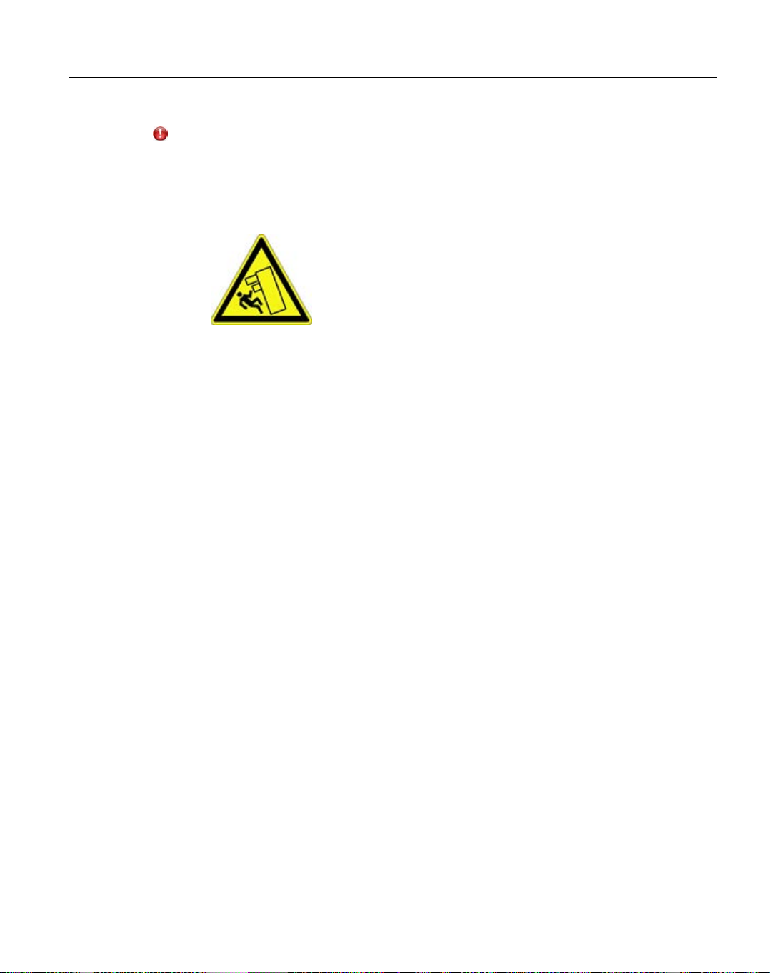
CAUTION!
l Never lift the devices into the rack using the handles on the front panel.
l For safety reasons, not more than one unit may be unlocked or pulled out of
the rack at a time, otherwise the rack may tip over.
This is illustrated by the following pictogram:
l If necessary, have other people help you mount the individual
components in the rack because of the weight involved.
l When connecting and disconnecting cables, observe the relevant
instructions in the "Important Information" chapter of the technical
manual for the corresponding rack. The technical manual is supplied with
the corresponding rack.
l Route cables in such a way that they do not form a potential hazard
(make sure no one can trip over them) and that they cannot be damaged.
l The rack must be connected to the power supply by an authorized
electrician approved by the local utility company.
l If the rack model is integrated into an installation that draws power from
an industrial power supply network with an IEC309 type connector, the
power supply's fuse protection must comply with the requirements for
non-industrial power supply networks for the type A connector.
l An ETERNUS CS800 configuration can carry a leakage current > 3.5
mA. Therefore, a ground connection must be established before
connecting to the mains.
1 Introduction
1.2.12 Environmental Protection
Environmentally-friendly product design and development
This product has been designed in accordance with the Fujitsu standard for "environmentally
friendly product design and development". This means that key factors such as durability,
selection and labeling of materials, emissions, packaging, ease of dismantling and recycling
have been taken into account.
ETERNUS CS800 23
Page 24
1.2 Important Information
This saves resources and thus reduces the harm done to the environment.
Energy-saving Information
Devices that do not need to be constantly switched on should be switched off until they are
needed as well as during long breaks and after completion of work.
Packaging Information
Do not throw away the packaging. You may need it later for transporting the system. If
possible, the equipment should only be transported in its original packaging.
Information on handling consumables
Please dispose of printer consumables and batteries in accordance with the applicable
national regulations.
In accordance with EU directives, batteries must not be disposed of with unsorted domestic
waste. They can be returned free of charge to the manufacturer, dealer or an authorized agent
for recycling or disposal.
All batteries containing pollutants are marked with a symbol (a crossed-out garbage can).
They are also marked with the chemical symbol for the heavy metal that causes them to be
categorized as containing pollutants:
Cd Cadmium
Hg Mercury
Pb Lead
Labels on plastic casing parts
Please avoid sticking your own labels on plastic parts wherever possible, since this makes it
difficult to recycle them.
Returns, recycling and disposal
The device must not be disposed of with domestic waste. This device is
labeled in compliance with European directive 2002/96/EC on waste
electrical and electronic equipment (WEEE).
This directive sets the framework for returning and recycling used
equipment and is valid across the EU. When returning your used device,
please use the return and collection systems available to you. Further
information can be found at http://www.ts.fujitsu.com/recycling
24 ETERNUS CS800
Page 25
Details regarding the return and recycling of devices and consumables within Europe can
also be found in the "Returning used devices" manual, via your local Fujitsu branch or from
our recycling center in Paderborn:
Fujitsu
Recycling Center
D-33106 Paderborn
Tel. +49 5251 8 18010
Fax +49 5251 8 333 18010
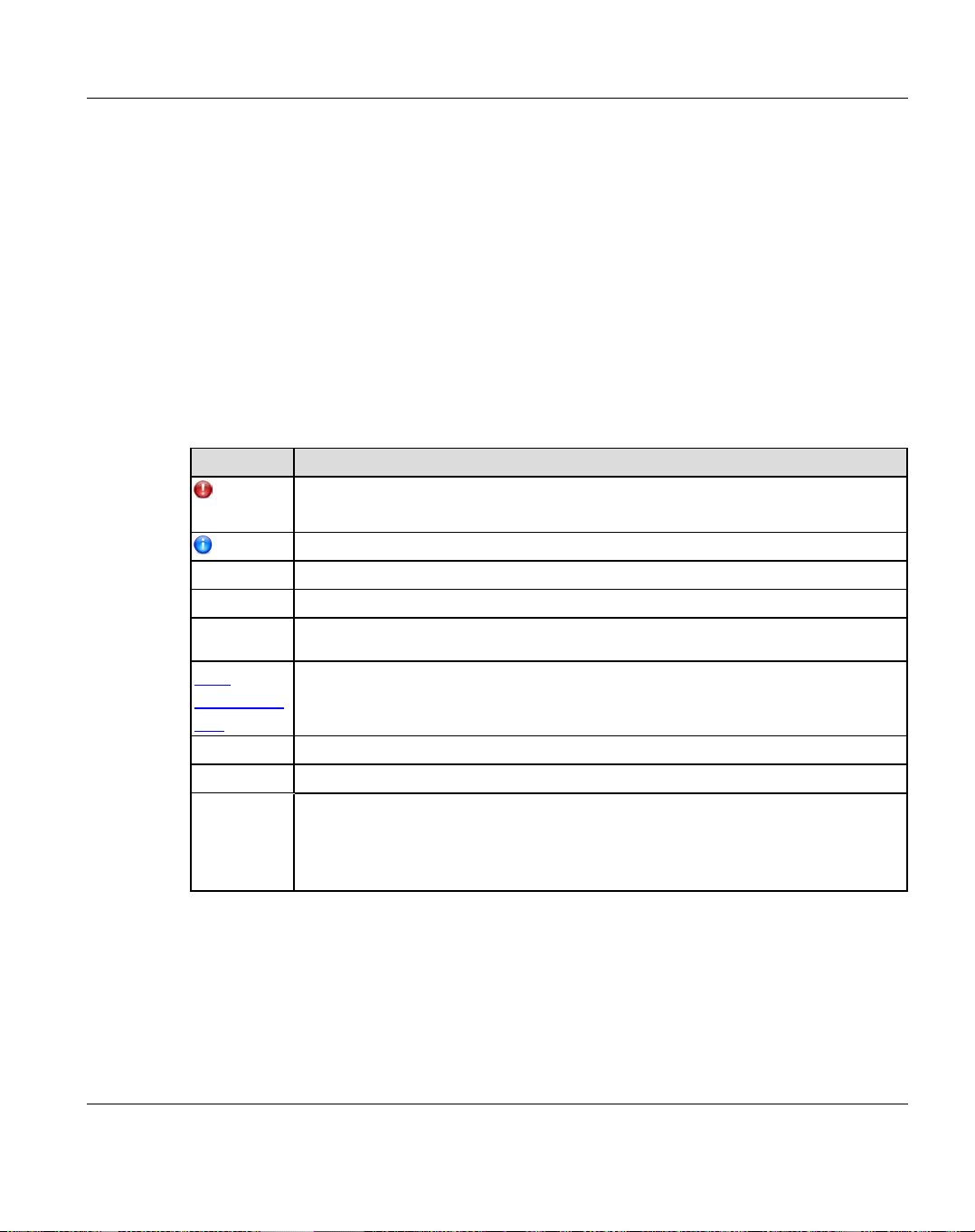
1.3 Typographic Conventions
The following typographic conventions are used:
Convention Explanation
Indicates various types of risk, namely health risks, risk of data loss and risk of
damage to devices.
Indicates additional relevant information and tips.
bold Indicates references to names of interface elements.
monospace
monospace
semibold
blue
continuous
text
<abc> Indicates variables which must be replaced with real values.
[abc] Indicates options that can be specified (syntax).
[key]
Indicates system output and system elements, e.g., file names and paths.
Indicates statements that are to be entered using the keyboard.
Indicates a link to a related topic.
Indicates a key on your keyboard. If you need to enter text in uppercase, the
Shift key is specified, for example, [SHIFT] + [A] for A. If you need to press
two keys at the same time, this is indicated by a plus sign between the two key
symbols.
1 Introduction
Screenshots
Some of the screenshots are system-dependent, so some of the details shown may differ
from your system. There may also be system-specific differences in menu options and
commands.
ETERNUS CS800 25
Page 26

26
Page 27

2 System Description
This chapter describes the features and build-up of the ETERNUS CS800 system. The
chapter consists of the following sections:
l "Overview" on page 28
l "Features and Benefits" on page 29
l "What’s New in ETERNUS CS800 S6 with Software V3.2" on page 30
l "Components ETERNUS CS800 S6 System" on page 30
l "Data Reduction" on page 34
l "Space Reclamation" on page 35
l "Remote Replication" on page 35
l "Storage Presentation" on page 36
l "Path to tape (PTT)" on page 39
l "ETERNUS CS800 Advanced Reporting" on page 40
l "Network Configuration" on page 40
ETERNUS CS800 27
Page 28

2.1 Overview
2.1 Overview
The ETERNUS CS800 is Fujitsu’s entry level and midrange disk backup solution that
integrates data deduplication and replication technology to connect backup and DR (disaster
recovery) protection across distributed corporate environments. The ETERNUS CS800 diskbased backup appliance uses Fujitsu’s patented data deduplication technology to increase
disk capacities by 10 to 50 times, and make WAN replication a practical, cost-effective part
of disaster recovery planning. The ETERNUS CS800 is designed for departmental and
medium business customers.
2.1.1 Disk-Based Backup Appliance
The ETERNUS CS800 system uses high speed disk RAIDs for backup data storage. In
comparison to a tape-based backup solution, the ETERNUS CS800 significantly reduces the
time required for backup/restore jobs and improves the reliability that backup jobs complete
within their planned backup window.
2.1.2 Advanced Data Deduplication Increasing Disk Retention for Backup Data
The ETERNUS CS800 leverages Fujitsu’s patented data deduplication technology (U.S.
Pat. No. 5,990,810) to dramatically increase the role that disk can play in the protection of
critical data. With the ETERNUS CS800 solution, users can retain 10 to 50 times more
backup data on fast recovery disk than with conventional arrays.
2.1.3 Remote Replication of Backup Data Providing Automated Disaster Recovery Protection
With the ETERNUS CS800, users can transmit backup data from a remote site to a central,
secure location to reduce or eliminate media handling. ETERNUS CS800 replication is
asynchronous, automated, and operates as a background process.
2.1.4 Configurable Storage Presentation
Storage can be presented in the following three ways:
l NAS shares.
l OST Logical Storage Units (LSUs)
l VTL (Virtual Tape Library) partitions
28 ETERNUS CS800
Page 29

The NAS and OST presentation are available on all ETERNUS CS800 models. The VTL
presentation is available on models with FC (Fibre Channel) option.
2.2 Features and Benefits
The ETERNUS CS800 system provides the following features and benefits:
l Leading performance and scalable capacity.
l Inline data flow provides leading deduplication with an optimal combination of total
system performance, manageability, and value.
l LAN/WAN replication to up to two targets and with up to 10 sources per target.
l High throughput connectivity options (10 GbE and 8 Gb Fibre Channel).
l Flexibility of VTL, NAS and OST presentation layers.
l Virtual Tape Library (VTL) presentation layer (all models with Fibre Channel option).
l Supported by every major backup software vendor.
l Tape drives emulated:
l IBM LTO-2, LTO-3, LTO-4, or LTO-5
l HP LTO-2, LTO-3, LTO-4, or LTO-5
l Libraries emulated:
l Fujitsu CS-TL
l ADIC Scalar i2000, or ADIC Scalar i500
l NAS presentation layer for NFS and CIFS.
l OST presentation layer for Symantec NetBackup and BackupExec. Supports also the
OST features
l Optimized Duplication
l Direct to Tape
l Synthetic Fulls
l OST Accent
l Path to tape (PTT) support for direct copy of backup data to a physical tape library,
supported by the following backup applications:
l Symantec™ NetBackup™ (with VTL and OST implementations)
l Symantec™ Backup Exec (with OST implementations)
l Oracle
l ASG-Time Navigator™
l EMC
®
Secure Backup
®
Networker®(versions prior to 8.1)
2 System Description
ETERNUS CS800 29
Page 30

2.3 What’s New in ETERNUS CS800 S6 with Software V3.2
l GUI for monitoring and management.
l Configuration Wizards provide guided assistance to help users configure key features of
the ETERNUS CS800, such as storage presentation and data replication. Each wizard
leads users step by step through the configuration process.
2.3 What’s New in ETERNUS CS800 S6 with Software V3.2
2.3.1 ETERNUS CS800 S6 Hardware
l Entry model consisting of a PRIMERGY RX2540 M1 server with one CPU and capacity
options of 8, 16 or 24 TB on internal disks.
l More powerful Entry model with a wider range of capacity options. This model consists
of a PRIMERGY RX2540 M1 server with two CPU’s and optionally up to three
ETERNUS JX40 S2 storage modules in addition to the internal disks. The provided
capacity varies between 8 and 120 TB.
l Scale model consisting of a PRIMERGY RX2540 M1 system and an ETERNUS DX100
S3 storage system. The provided capacity varies between 32 and 352 TB.
2.3.2 ETERNUS CS800 S6 V3.2 Software
l New blockpool with significant performance improvements in some cases.
l Support of Symantec NetBackup Accelerator.
l Access to root and service logins can be managed by the administrator now.
l Samba 4 and SMB3 - Samba 4 will auto-negotiate with the client up to SMB3.
2.4 Components ETERNUS CS800 S6 System
An ETERNUS CS800 S6 system consists of a server component, which is the PRIMERGY
RX2540 M1 server, and of storage components, which are up to three optional ETERNUS
JX40 S2 for ETERNUS CS800 S6 Entry and ETERNUS DX100 S3 for ETERNUS CS800
S6 Scale.
The following versions of the ETERNUS CS800 S6 are provided:
l "Entry" on page 31
l "Scale" on page 32
30 ETERNUS CS800
Page 31

2.4.1 Entry
This version provides a base amount of network throughput and data storage facility. It
includes the following features:
l Server unit with
l 5 x 1GbE ports for NFS and CIFS (to the customer LAN)
l Optionally with the two-CPU model: Up to three JX40 S2 storage modules, providing 16,
32, 48, 64, 80 or 96TB of additional disk capacity (field upgradeable option)
l Optionally: 2 x 8Gb Fibre Channel ports (factory installed option)
l Optionally: 2 x 10GbE (factory installed option/field upgradeable on special release only)
With the Entry model, either 4x2.5" 600GB (one-CPU model) or 6x2.5 900GB (two-CPU
model) SAS hard disk (10,000 rpm) are building up RAID 1 disk groups used for the operating
system and backup metadata. Further 6 or 12 or 18 × 2.5" 2TB SATA hard disks (7,200 rpm)
are building up RAID 6 (4+2) disk groups used as the backup storage with a capacity of 8TB,
16TB or 24TB.
The two-CPU Entry model with an entire capacity of more than 24TB uses up to three
ETERNUSJX40 S2 storage modules with either 6 or 12 x 3.5" 2TB SATA hard disks (7,200
rpm) per JX40 building up one to six additional RAID 6 (4+2) disk groups for backup data.
2 System Description
o
either 1 CPU (6 cores / 12 threads) and 128GB RAM to provide a backup capacity
between 8 and 24TB
o
or 2 CPU's (6 cores / 12 threads each) and 256GB RAM to provide a backup
capacity between 8 and 120TB
Figure 2: Front View of an Entry System (Example)
ETERNUS CS800 31
Page 32

2.4 Components ETERNUS CS800 S6 System
2.4.2 Scale
This version provides a midrange amount as well as fast network throughput and full data
storage facility. It includes the following features:
l 1 server unit with 2 CPUs (8 cores / 16 threads each) and 256GB RAM
l Backup capacity between 32 and 352TB (ETERNUS DX100 S3 with optionally up to 10
expansion modules, field upgradeable).
l 3 x 1GbE ports for NFS and CIFS (to the customer LAN)
l Optionally: 1 to 10 storage expansion modules, with 32TB usable capacity each.
l Optionally: 4 x 10GbE (factory installed option/field upgradeable on special release only)
l Optionally: 8 x 1GbE (factory installed option)
l Optionally: 4 x 8GbFC (always factory installed)
l Optionally: Hot Spares in ETERNUS DX100 S3 (factory enabled)
l The 1st storage expansion shelf of the DX100 S3 will be equipped with 12 x Hot
Spare disks.
l This will reduced the max. capacity to 320TB.
The Scale model uses an DX100 S3 storage array with large capacity, highly cost effective
Nearline SAS disks (Serial Attached SCSI). Twelve disks of 3.5'' size with a capacity of 4TB
each and a speed of 7,200 rpm are implemented to each module of the storage array. Always
six disks are building up a RAID 6 (4+2) disk group, i.e. there are two RAID 6 groups in each
storage module. In addition, sixteen SAS disks of size 2.5" with a capacity of 900GB each
and a speed of 10,000 rpm are implemented in the server. Two disks are reserved as hot
spare, the other ones are used by the operating system and to store the backup metadata.
32 ETERNUS CS800
Page 33

Figure 3: Front View of a Scale System (Example)
2 System Description
2.4.3 Capacity of ETERNUS CS800 S6 Configurations
Name Disk
Size
Entry 2 TB 8 TB 2 x 8 TB 24 TB
Entry with
JX40 S2
option
Scale 4 TB 32 TB 32 TB 352 TB
Scale with
Hot
Spare Disks
ETERNUS CS800 33
2 TB,
4 TB
4 TB 32 TB 32 TB 320 TB
Minimum
Capacity
8 TB 2 x 8 TB
Capacity Increment
steps
6 x 16 TB
Maximum
Capacity
120 TB
Page 34

2.5 Data Reduction
2.5 Data Reduction
Data reduction is the process of reducing the amount of storage capacity required to store
your data. The ETERNUS CS800 systems provide two techniques to optimize the storage
space required on your system:
l "Data Deduplication" on page 34
l "Compression" on page 34
2.5.1 Data Deduplication
The ETERNUS CS800 system disk backup and replication systems use Fujitsu Technology
Solutions patented data deduplication technology to dramatically increase the role that disk
can play in data protection. With ETERNUS CS800 solutions, users can retain 10 to 50
times more backup data on fast recovery disk than with conventional arrays. This advantage
allows IT departments to cost-effectively retain months of backup data on disk for faster,
more reliable restores and more data recovery points. Fujitsu’s innovative implementation of
this core technology means that users do not have to compromise on performance to take
advantage of extended retention capability. Inline data flow provides streamlined
deduplication that offers a maximum combination of total system performance,
manageability, and value.
Fujitsu's deduplication technology uses a sub-file, variable-length approach to identify
redundant blocks in a data stream—blocks that have appeared before in the same dataset or
in datasets processed at an earlier time. When a block appears that has already been stored,
the ETERNUS CS800 system inserts a reference pointer to the earlier instance of the data
segment instead of storing another copy. The result is a dramatic reduction in the storage
capacity needed to store the data set, and a similar reduction in the bandwidth needed to
replicate deduplicated data sets over a network.
2.5.2 Compression
The ETERNUS CS800 systems use compression technology after duplicate blocks have
been identified and replaced as part of the deduplication process. With compression, unique
data that has been through the data deduplication process can be compressed at a typical
ratio of approximately 2:1. This enables you to maximize the storage capacity of your
system.
34 ETERNUS CS800
Page 35

2.6 Space Reclamation
The space reclamation process performs multiple functions on the ETERNUS CS800.
When data is deduplicated it is stored in a block pool - a pool of all unique data blocks that
were captured during the data deduplication cycle. When subsequent backup jobs occur, the
data deduplication engine searches for new data entering the ETERNUS CS800 and uses a
variable length compression algorithm to compare new data to existing data in the block pool.
Unique blocks are added to the block pool and known blocks are indexed.
The space reclamation function searches the blockpool for data blocks that are not
referenced by any pointers (that is, the files associated with the block have been expired and
removed). Once such a data block is identified, the block is removed to make the space
reusable.
For correct system operation, space reclamation must be run at regular intervals (at least
once a week). Fujitsu Technology Solutions recommends creating a schedule to
automatically run space reclamation (see "Scheduling Space Reclamation" on page 293).
It may be beneficial to schedule space reclamation for a time when other operations are not
normally being carried out. Therefore it is important to know when to schedule the space
reclamation process. As best practice it is recommended that this process commences at
least two hours after your backup job has completed on a daily basis. It is far more efficient to
process a day’s worth of new data than a week’s worth.
2 System Description
2.7 Remote Replication
Today most backup occurs on isolated devices, making it difficult to deploy disk backup
when disaster recovery protection is required. ETERNUS CS800 solutions use data
deduplication and replication to decrease by up to 50 times the bandwidth required to move
backup data over networks and between sites. This dramatic gain makes it practical and
cost-effective for users to replicate backup data over WANs for secure, network-based
disaster recovery protection, and it lets users combine rapid, local restores with sound
disaster recovery protection.
With ETERNUS CS800 replication, users can transmit data from a single site or multiple
sites to a central location using any ETERNUS CS800.The replication is an asynchronous,
automated background process that includes encryption of data in transit. This model for
protecting the distributed enterprise allows users to combine disk, replication, and tape for an
optimal combination of performance, simplicity, and security.
For more information on implementing a replication plan, see "ETERNUS CS800 Replication
Overview" on page 363.
ETERNUS CS800 35
Page 36

2.8 Storage Presentation
A ETERNUS CS800 can only replicate data to an ETERNUS CS800 that supports the
same protocol as the ETERNUS CS800 (NAS or VTL). That is, an ETERNUS CS800
VTL system can only replicate data to a ETERNUS CS800 that supports VTL.
2.8 Storage Presentation
The ETERNUS CS800 presents its disk storage using multiple protocols:
l "Virtual Tape Storage" on page 36
l "Network Attached Storage (NAS)" on page 37
l "OpenStorage (OST)" on page 39
2.8.1 Virtual Tape Storage
A virtual tape storage or virtual tape library (VTL) presentation allows the storage space on
these hard drives to appear to the backup application as tape cartridges (DLT or LTO). Data
is stored on the hard drives through an interface that appears as a tape library, with virtual
cartridges, virtual drives, and a virtual changer mechanism. An ETERNUS CS800 with a
VTL or Multi-Protocol configuration can be configured to present multiple VTL interfaces of
different sizes and types at once. This allows backup applications to recognize and integrate
a ETERNUS CS800 system into a data center environment just like one or more physical
tape libraries. ETERNUS CS800 provides a number of tape drive and library emulations
including the tape drive emulations:
l IBM LTO-2, LTO-3, LTO-4, or LTO-5
l HP LTO-2, LTO-3, LTO-4, or LTO-5
and the library emulations:
l Fujitsu CS-TL
l ADIC Scalar i2000, or ADIC Scalar i500
36 ETERNUS CS800
Page 37

Figure 4: Virtual Tape Library (VTL)
2.8.2 Network Attached Storage (NAS)
The ETERNUS CS800 system has the ability to serve as a NAS backup system (see
"Network Attached Storage (NAS)" on page 37) where the following protocols are supported:
l "CIFS Protocol" on page 37
l "NFS Protocol" on page 38
2 System Description
Figure 5: NAS Backup using CIFS and NFS
NAS shares are optimized for backup (i.e. typically large files) rather than file
sharing. When used with many small files, the performance may be degraded.
2.8.3 CIFS Protocol
The CIFS (Common Internet File System) protocol defines a standard for remote file access
from many computers at a time in Windows environments.
ETERNUS CS800 37
Page 38

2.8 Storage Presentation
Active Directory Support
The ETERNUS CS800 supports ADS (Active Directory Services) as well as ACLs (Access
Control Lists). This provides the following benefits:
l Compatibility with CIFS domains - NAS shares are able to join CIFS domains and
use domain authentication.
l Precise control of file system permissions - Administrators can specify which users
and groups can perform what actions.
l Robust administrative support - Administrators have the same implicit permissions as
they do in Windows operating systems.
Windows 2008, Windows 2008 R2, and Windows 2012 R2 are supported for Active
Directory domain membership.
When you create a CIFS share, the initial permissions are the same as the default
permissions for a Windows 2003 share with the addition of an ACE (Access Control
Entry) that permits full access to the share for all authenticated users. Administrators
can choose to remove this full access ACE, set up custom permissions, or leave the
ACL (Access Control List) as is if the server is set up in a fully trusted environment.
2.8.4 NFS Protocol
The NFS (Network File System) protocol allows network users to access shared files stored
on computers of different types. NFS provides access to shared files through an interface
called the Virtual File System (VFS) that runs on top of TCP/IP. With NFS, computers
connected to a network operate as clients while accessing remote files, and as servers while
providing remote users access to local shared files. This protocol is used with UNIX and
Linux networks. It can also be used with Windows networks.
38 ETERNUS CS800
Page 39

2.8.5 OpenStorage (OST)
With the OST presentation, the ETERNUS CS800 system presents storage servers to a
Symantec NetBackup or Backup Exec media server through a specific Symantec protocol. A
storage server consists of logical storage units (LSUs), which are similar to directories in a
NAS file system or tape cartridges in a VTL partition.
The OST presentation requires the Symantec NetBackup (7.1.x or later) or Backup Exec
2010 R3 or later host application and the OST Plug-in client installation on the media server.
Windows 2012 64-bit requires Symantec NetBackup (7.6 or later) or Backup Exec 2014
or later.
Plug-in clients are host-OS dependent and are supplied by Fujitsu Technology Solutions. To
use the ETERNUS CS800 in OST mode, you must configure an OST storage server and
LSUs on the ETERNUS CS800. You must also map the LSUs on the NetBackup server so
that NetBackup can perform backups and restore from them. Additionally, policies for
optimized duplication (OST replication) and OST direct to tape may need to be set on the
NetBackup server.
2 System Description
Figure 6: OpenStorage (OST) Example
2.9 Path to tape (PTT)
The path to tape (PTT) capability allows writing data stored in the ETERNUS CS800 to a
tape library which is attached to an FC port of the ETERNUS CS800 system. With path to
ETERNUS CS800 39
Page 40

2.10 ETERNUS CS800 Advanced Reporting
tape, backup data can be moved directly from the ETERNUS CS800 system to a tape library
without the need to travel through a backup host. A common use case for PTT is to create
removable media for long term storage. Path to tape is available on all ETERNUS CS800
models with FC port option. PTT is supported by a number of backup applications
including:
l Symantec™ NetBackup™
l Symantec™ Backup Exec
l Oracle® Secure Backup
l Atempo Time Navigator™
l EMC® Networker before version 8.1
2.10 ETERNUS CS800 Advanced Reporting
Fujitsu Technology Solutions ETERNUS CS800 Advanced Reporting works with all
ETERNUS CS800-Series disk backup systems. ETERNUS CS800 Advanced Reporting
combines comprehensive performance data logging with powerful visual reporting and
analysis tools to help you identify potential problems and optimize system operation. For
more information, refer to the Advanced Reporting User’s Guide.
2.11 Network Configuration
During network configuration, each individual interface on the ETERNUS CS800 can be
configured as a subnet with its own network settings. Each physical Ethernet port can be
configured as an interface. In addition, you can also create bonded interfaces (logical ports)
consisting of two or more physical ports.
Keep in mind that any traffic can pass through any of the configured Ethernet ports. This
means that the routing of different traffic types, as well as firewall capability, must be
controlled using the network infrastructure (routers and switches) that the ETERNUS CS800
is connected to.
For more information about configuration network settings, see "Network" on page 319.
Each configured network interface requires its own set of network settings (IP address,
network mask, and gateway).
For effective bonded network use, a properly configured network switch is required. The
ETERNUS CS800 bonding settings must match the switch settings. If the switch settings
and the ETERNUS CS800 settings do not match, your system may become inaccessible
through the switch.
40 ETERNUS CS800
Page 41

2 System Description
Each configured network interface requires its own set of network settings (IP
address, network mask, and gateway). of Linux.
CAUTION!
For effective bonded network use, a properly configured network switch is required. (A
network switch is not supplied with the ETERNUS CS800).The ETERNUS CS800
bonding settings must match the switch settings. If the switch settings and the
ETERNUS CS800 settings do not match, your system may become inaccessible
through the switch.
Performance Guidelines
The throughput and resilience of a ETERNUS CS800 depends on various parameters,
such as
l on the model and configuration level (Entry/Scale, interfaces, the number of disk drives)
l the data which should be backed up (deduplicable, compressible, new or already stored
in the blockpool)
l the backup software and the method used by it
l the client operating system
l the presentation layer (NFS, CIFS, VTL, OST)
l non-backup jobs performed in parallel (replication, space reclamation)
Therefore a general recommendation cannot be given here. As a rough guideline only: If each
backup file/job written concurrently to the system is considered as a stream, maximum of
throughput is reached with 16 to 32 (Scale) or 5 to 16 (Entry) streams in parallel. The
given ranges are appropriate for the configuration levels and the presentation layers used in
parallel.
NAS shares provided by ETERNUS CS800 are optimized for backup. Using NAS
shares to store many small files may degrade the throughput of the system (e.g.
inline throughput, replication) significantly.
Contact Fujitsu Customer Support if you need assistance.
ETERNUS CS800 41
Page 42

42
Page 43

3 Hardware Description
This chapter describes the hardware features and basic operation of the ETERNUS CS800
hardware, including:
l "Server" on page 43
l "Storage Modules" on page 61
l "Hard Drive Carrier" on page 74
l "Turning On and Shutting Down the System" on page 76
l "Locating the Serial Number" on page 77
This chapter applies to ETERNUS CS800 S6 hardware only. For an ETERNUS
CS800 S5 system see ETERNUS CS800 S5 User Guide. For an ETERNUS CS800
S4 system see ETERNUS CS800 S4 User Guide. For an ETERNUS CS800 S2/S3
system see ETERNUS CS800 S3 User Guide.
3.1 Server
The server systems used by ETERNUS CS800 S6 is PRIMERGY RX2540 M1 that provides
control for the ETERNUS CS800 S6 software (operating system and software applications).
All ETERNUS CS800 S6 systems have one server.
For detailed information on PRIMERGY RX2540 M1 see:
l FUJITSU Server PRIMERGY RX2540 M1
l FUJITSU Server PRIMERGY RX2540 M1 Data Sheet
3.1.1 Server Front View
This chapter describes the front view of the servers, including features and indicators.
Figure 7: ETERNUS CS800 Entry servers' front view
ETERNUS CS800 43
Page 44

3.1 Server
Figure 8: ETERNUS CS800 Scale servers' front view
The figure below shows the indicators, buttons and connectors on the front panel modules of
the ETERNUS CS800.
Figure 9: Front panel indicators and buttons
The table below describes each item.
Item Indicator, Button, Port Description
1 Reset button Pressing the Reset button reboots the system. It can be
pressed using the end of a paper clip.
CAUTION!
Risk of data loss!
44 ETERNUS CS800
Page 45

3 Hardware Description
Item Indicator, Button, Port Description
2 NMI button This button is used to troubleshoot software and device
driver errors. It can be pressed using the end of a paper
clip.
CAUTION!
Do not press! Risk of data loss! The NMI button may
only be used by service.
3 ID indicator /
ID button
The ID button highlights the ID indicator on the front and
I/O panels for easy server identification.
The ID indicator lights up blue on the front and on the rear of
the server when the ID button is pressed. Both ID
indicators are synchronized.
4 CSS indicator (yellow) Does not light up
when no critical event was detected for a CSS
(Customer Self Service) component.
Lights up yellow
if a prefailure event was detected for a CSS
component that you can fix yourself (for reasons of
precaution) with the CSS concept.
Flashes yellow
if an error was detected that you can fix yourself with
the CSS concept.
If the event is still acute after a power failure, the indicator
is activated after the restart. The indicator also lights up in
standby mode.
ETERNUS CS800 45
Page 46

3.1 Server
Item Indicator, Button, Port Description
5 Global Error indicator
(orange)
6 HDD/SSD activity
indicator
Lights up orange
if a prefailure event has been detected that requires
(precautionary) service intervention (non
CSScomponent).
Flashes orange
if an error was detected that requires service
intervention (non CSScomponent)..
Does not light up
if there is no critical event.
If the event is still acute after a power failure, the indicator
is activated after the restart. The indicator also lights up in
standby mode.
Flashes green
when an internal drive is being accessed.
46 ETERNUS CS800
Page 47

Item Indicator, Button, Port Description
3 Hardware Description
7 ON/OFF button /
Power-on indicator
(green)
The ON/OFF button is used to switch the server on and off.
The ON/OFF button does not disconnect the server
from the mains voltage (standby mode). To
disconnect from the mains completely, remove the
power plug(s).
CAUTION!
Risk of data loss! It is highly recommended to shut
down the system using the appropriate functionality
of the system's software.
Especially do not press the ON/OFF button more
than once to power off the system.
The Power-on indicator is off:
the server is in power-off mode.
The Power-on indicator lights up green:
l the system has been switched on and is in power-on
delay or
l the system is powered on and in normal operation (S0)
The Power-on indicator flashes green slowly (1/2 Hz):
iRMC S4 is not ready.
8 Power-off indicator
(ACconnected)
(green)
The Power-off indicator is off:
l the system is not connected to the mains or
l the system is powered on and in normal operation (S0)
The Power-off indicator lights up green:
l the system is in power-off mode but connected to the
mains (AC connected)or
l the system has been switched on and is in power-on
delay
After connecting the server to the mains it takes
about 60 seconds until the server enters the standby
mode.
Table 1: Front panel indicators, buttons and connectors
ETERNUS CS800 47
Page 48

3.1 Server
3.1.2 Server Rear View - Connectors and Indicators
This chapter describes the rear view of the servers including connectors and indicators.
Figure 10: Rear view of the ETERNUS CS800
Item Description
1 Redundant power supplies
1a Power supply indicator
Lights up yellow)
when the server is switched off, but mains voltage is present (standby mode).
Lights up green
when the server is switched on and functioning properly.
Lights up orange
if the power supply unit has failed.
2 I/O panel (for detailed information on the servers' I/O panels, see the figure below)
3 Depending of the ETERNUS CS800
Table 2: Rear panel connectors and Indicators of the servers
48 ETERNUS CS800
Page 49

3 Hardware Description
Connectors and indicators on the I/O panels
Figure 11: I/O panel connectors and indicators
The first table below describes the connectors on the I/O panels of the ETERNUS CS800
servers (1, 2, ... in the figure above). The second table contains the indicators located on the
rear side I/O panels of the servers (marked with A,B,...).
Item Description
1 USB 2.0 connector(s)
2 Dynamic LoM
The LAN connectors on the dynamicLoM modules are numbered in ascending order
from right to left beginning with "0". The rightmost connector (LAN 0) is the service
port.
3 USB 3.0 connectors (SuperSpeed USB)
4 Management LAN connector
(for iRMC S4 server management function)
5 Video connector (VGA)
Table 3: Connectors on the I/O panel
ETERNUS CS800 49
Page 50

3.1 Server
Item Indicator Status Description
At each LAN connector (Dynamic LoM, Management LAN connector) you will find
the following indicators
A LAN link/transfer
indicator
B LAN speed
indicator
C Global error
indicator
CSS indicator off no critical event (CSS component)
ID indicator blue on server has been highlighted using
green on LAN connection established
off no LAN connection
green flashing data transfer in progress
yellow on transfer rate of 1 Gbit/s
green on transfer rate of 100 Mbit/s
off transfer rate of 10 Mbit/s
off no critical event (non CSS component)
orange on prefailure event detected (non CSS
component)
orange flashing non CSS component failure
orange on prefailure event detected (CSS
component)
orange flashing CSS component failure
ServerView Operations Manager or the ID
button on the front panel for easy
identification
blue flashing local monitor is not active
50 ETERNUS CS800
Page 51

Item Indicator Status Description
3 Hardware Description
D Global Error
indicator (visible
through the chassis
perforation)
yellow on A prefailure event has been detected that
requires (precautionary) service
intervention.
yellow flashing An error was detected that requires service
intervention.
off There is no critical event.
If the event is still acute after a power
cycle, the indicator is activated after the
restart.
The indicator also lights up in standby
mode.
You can find more details on the indicated
errors in the System Event Log (SEL), in
the ServerView Operations Manager or via
the iRMC S4's Web interface.
ID indicator (visible
through the chassis
perforation)
blue on The system has been selected by pressing
the ID button in the front of the server. To
deactivate the indicator, press the button
again.
E CSS indicator yellow on A prefailure event was detected for a CSS
component that you can fix yourself (for
reasons of precaution) with the CSS
concept.
yellow flashing An error was detected that you can fix
yourself with the CSS concept.
off The system is OK.
If the event is still acute after a power
cycle, the indicator is activated after the
restart.
Table 4: Indicators on the I/O panel
For detailed information on the ETERNUS CS800 S6 see PRIMERGY RX2540 M1 manual.
ETERNUS CS800 51
Page 52

3.1 Server
3.1.3 Connecting the servers to the mains
The ETERNUS CS800 servers are equipped with two hot-plug power supply units. If one
power supply unit is defective, then the other guarantees unimpaired operation. Each hot-plug
power supply unit can be replaced during operation.
CAUTION!
The server is automatically set to a mains voltage in the range 100 V - 240 V. You
may only operate the server if its rated voltage range corresponds to the local
mains voltage.
Connect the power cord with the insulated connector to the power supply unit of the
server, and plug the power plug into a grounded outlet on the mains socket strip on the
rack (see Technical Manual of the rack).
A phase redundancy in the power supply of the server can be set up if each of the
power supply units is either connected to two different phases or to two separate
circuits of the internal power supply network.
Using the cable clamp
You can secure the power cords in a cable clamp to ensure that the insulated connectors
cannot be disconnected from the server accidentally.
Figure 12: Cable clamp
1. Pull the cable clamp up (2).
2. Thread the power cord through the cable clamp (1).
3. Press the cable clamp down until it engages to secure the cable (3).
52 ETERNUS CS800
Page 53

Notes on connecting/disconnecting cables
CAUTION!
l Always read the documentation supplied with the device you wish to connect.
l Never connect or disconnect cables during a thunderstorm.
l Never pull on a cable when disconnecting it. Always take hold of the cable by
the plug. Be sure to wait for 10 seconds or more after shutdown before turning
the server on.
l Follow the sequences described below to connect or disconnect external
devices to or from the server:
Connecting cables
Turn off all power and equipment switches
Disconnect all power plugs from the properly grounded power outlets.
Connect all cables to the server and peripherals.
Plug all data communication cables into the utility sockets.
Plug all power cords into the properly grounded power outlets.
Disconnecting cables
Turn off all power and equipment switches.
Disconnect all power plugs from the properly grounded power outlets.
Unplug all data communication cables from the utility sockets.
Disconnect the relevant cables from the server and all the peripherals
3 Hardware Description
For connecting or disconnecting LAN cables, the server does not need to be
powered off. To avoid loss of data either stop the I/O or make sure the cable is
redundant, i.e. a member of a bond.
Information for ensuring electromagnetic compatibility.
All data and signal cables must have sufficient shielding. The use of cable type S/FTP Cat5e
or better is recommended. Use of unshielded or badly shielded cables may lead to increased
emission of interference and/or reduced fault-tolerance of the device.
ETERNUS CS800 53
Page 54

3.1 Server
3.1.4 ETERNUS CS800 S6 - Entry System
The following figures show the HDDplacement on the front and equipping of the slots on the
rear panel for the Entry System configuration.
Figure 13: Entry System - front , with JX40 S2 Option
Figure 14: Entry System - front, without JX40 S2 Option
3.1.4.1 PCI Cards for ETERNUS CS800 S6 Entry
Entry with JX40 S2 Option
Figure 15: Entry System, no option variant
Figure 16: Entry System with 10 Gb/s Ethernet
54 ETERNUS CS800
Page 55

3 Hardware Description
Figure 17: Entry System with 8 Gb/s Fibre Channel
Figure 18: Entry System with 8 Gb/s Fibre Channel and with 10 Gb/s Ethernet
Variants Slots
1 2 3 4 5 7
no option internal
RAID
- Riser
card
4 x 1 Gb/s
Ethernet
controller
with 10 Gb/s
Ethernet option
internal
RAID
- Riser
card
4 x 1 Gb/s
Ethernet
controller
with 8 Gb/s
Fibre Channel
option
with 10 Gb/s
Ethernet and
with 8 Gb/s
internal
RAID
controller
internal
RAID
controller
2 x 8 Gb/s
Fibre Channel
2 x 8 Gb/s
Fibre Channel
Riser
card
Riser
card
4 x 1 Gb/s
Ethernet
4 x 1 Gb/s
Ethernet
Fibre Channel
option
Table 5: Usage of PCI Slots - Entry System, with JX40 S2 option
- external
RAID
controller
2 x 10 Gb/s
Ethernet
external
RAID
controller
- external
RAID
controller
2 x 10 Gb/s
Ethernet
external
RAID
controller
ETERNUS CS800 55
Page 56

3.1 Server
Entry without JX40 S2 Option
Figure 19: Entry System, no option variant
Figure 20: Entry System with 10 Gb/s Ethernet
Figure 21: Entry System with 8 Gb/s Fibre Channel
Figure 22: Entry System with 8 Gb/s Fibre Channel and with 10 Gb/s Ethernet
56 ETERNUS CS800
Page 57

Variants Slots
1 2 3 4 5
3 Hardware Description
no option internal
- Riser
RAID
controller
with 10 Gb/s Ethernet option internal
- Riser
RAID
controller
with 8 Gb/s Fibre Channel
option
internal
RAID
2 x 8 Gb/s
Fibre Channel
controller
with 10 Gb/s Ethernet and 8
Gb/s Fibre Channel option
internal
RAID
2 x 8 Gb/s
Fibre Channel
controller
Table 6: Usage of PCI Slots - Entry System, without JX40 S2 option
card
card
Riser
card
Riser
card
4 x 1 Gb/s
Ethernet
4 x 1 Gb/s
Ethernet
4 x 1 Gb/s
Ethernet
4 x 1 Gb/s
Ethernet
-
2 x 10 Gb/s
Ethernet
-
2 x 10 Gb/s
Ethernet
ETERNUS CS800 57
Page 58

3.1 Server
3.1.5 ETERNUS CS800 S6 - Scale System
The following figures show the HDDplacement on the front and equipping of the slots on the
rear panel for the Scale System configuration.
Figure 23: Scale System - front
3.1.5.1 PCI Cards for ETERNUS CS800 S6 Scale
Figure 24: Scale System, no option / FC option variant
Figure 25: Scale System with 1 Gb/s Ethernet option
Figure 26: Scale System with 10 Gb/s Ethernet option
58 ETERNUS CS800
Page 59

Variants Slots
1 2 3 4 5 7 8 9 10 11
3 Hardware Description
with
none
or FC
option
with
10Gb/s
Ethernet
option
with
1Gb/s
Ethernet
option
Table 7: Usage of PCI Slots - Scale System
internal
RAID
controller
internal
RAID
controller
internal
RAID
controller
2 x 8
Gb/s
Fibre
Channel
2 x 8
Gb/s
Fibre
Channel
2 x 8
Gb/s
Fibre
Channel
Riser
card
Riser
card
Riser
card
3.1.6 Indicators on the PCI Cards
- - 4 x 1
Gb/s
Ethernet
2 x 10
Gb/s
Ethernet
4 x 1
Gb/s
Ethernet
- 4 x 1
Gb/s
Ethernet
- 4 x 1
Gb/s
Ethernet
2 x 8
Gb/s
Fibre
Channel
2 x 8
Gb/s
Fibre
Channel
2 x 8
Gb/s
Fibre
Channel
Riser
card
Riser
card
Riser
card
- 2 x 8
Gb/s
Fibre
Channel
2 x 10
Gb/s
Ethernet
4 x 1
Gb/s
Ethernet
2 x 8
Gb/s
Fibre
Channel
2 x 8
Gb/s
Fibre
Channel
Figure 27: Indicators on the PCI Cards
ETERNUS CS800 59
Page 60

3.1 Server
Slots Variants
Item
LED (green) Link/Activity indicator
1
Does not light up if there is no link.
Flashes green when a data transfer is in progress.
LED (green) Connectivity indicator
2
Lights up green if a LAN connection exists.
Does not light up if no LAN connection exists.
LED 1
3
(green/yellow)
Data rate indicator
Does not light up in case of input/output activity with 10 Mb/s.
Lights up green in case of input/output activity with 100 Mb/s.
Lights up yellow in case of input/output activity with 1 Gb/s.
LED 2 (green) Link/Activity indicator
4
Lights up green if a valid connection exists.
Does not light up if there is no link Flashes green when a data
transfer is in progress.
LED 1 (yellow) Link/Activity indicator
5
Lights up yellow if a 8 Gb/s link exists.
Flashes in case of input/output activity with 8 Gb/s.
LED 2 (green) Link/Activity indicator
6
Lights up green if a 4 Gb/s link exists.
Flashes in case of input/output activity with 4 Gb/s.
LED 3 (amber) Link/Activity indicator
7
Lights up amber if a 1 Gb/s link exists.
Flashes in case of input/output activity with 1 Gb/s.
Table 8: Indicators on the PCI Cards
60 ETERNUS CS800
Page 61

3.2 Storage Modules
The Entry model of ETERNUS CS800 S6 with a capacity of more than 24TB uses up to three
ETERNUS JX40 S2 storage modules as backup data storage.
The Scale model of ETERNUS CS800 S6 uses ETERNUS DX100 S3 storage modules as
backup data storage. There are two variants of the ETERNUS DX100 S3 storage modules:
l a storage base module which is connected to the server component, and up to ten
optional
l storage expansion modules to provide additional capacity for backup data.
For detailed information on storage modules, see:ETERNUS JX and ETERNUS DX storage
module manuals
3.2.1 ETERNUSJX40 S2 Front View
ETERNUS JX40 S2 goes just with Entry model only.
This chapter describes the front view of JX40 S2 storage module, which includes panel
features and indicator.
The ETERNUS JX40 storage module contains 12 3.5-inch SAS hard disk drives in the front
and one controller module and two power supplies in the rear.
3 Hardware Description
Figure 28: Front view of the JX40 S2 Module
ETERNUS CS800 61
Page 62

3.2 Storage Modules
Operation panel of JX40
Figure 29: Operation panel of JX40 S2
LED name LED status Description
POWER
LED
FAULT
LED
IDENTIFY
LED
Table 9: Status and meanings of each LED (operation panel of JX40 S2 module)
green DC power is supplied to the JX40 S2 module.
amber The JX40 S2 module is in error status.
blinks blue Specifies the installation location of the storage subsystem.
3.2.2 ETERNUS JX40 S2 Rear View
This chapter describes the rear view of JX40 S2 storage module, which includes connectors
and indicators.
62 ETERNUS CS800
Page 63

Figure 30: Rear view of JX40 S2
Figure 31:
3 Hardware Description
Figure 32: Rear view of JX40 S2- I/O module
LED name LED status Description
SAS INlink green The link between the SAS IN port and the source port has
been established.
SAS IN fault amber The ports to remove the mini SAS HD cables between
enclosures from are indicated. This occurs while a drive
enclosure is being added.
SASOUT link green The link between the SAS OUT port and the destination port
has been established.
SASOUTfault amber The link between the SAS OUT port and the destination port is
in error status.
ETERNUS CS800 63
Page 64

3.2 Storage Modules
LED name LED status Description
READY LED green The I/O module is in normal status.
IDENTIFY
blue Identifies the installation location of the I/O module.
LED
FAULT LED amber The I/O module is in error status.
Table 10: Status and meanings of each LED (I/O module)
Power Supply Units
The power supply unit transforms input AC power from a power socket to DC power and
supplies power to each component.
Each power supply unit contains fans.
Figure 33: Power supply unit (PSU) of the ETERNUS JX40 S2
Explanation
l Inlet: This inlet is used to connect a power cord.
l PSU switch: This switch is used to turn on and off the AC power supply.
64 ETERNUS CS800
Page 65

LED name LED status Description
3 Hardware Description
POWER LED green
blinks green
AC power is supplied to the power supply unit.
AC power is supplied to the power supply unit, but
DC power is not supplied to the storage
subsystem.
FAULT LED amber AC power is not supplied to the power supply unit.
AC MISSING
LED
amber AC power is not supplied to this power supply
unit, but AC power is supplied to the other power
supply unit.
FANLED amber The power supply unit or the fan in the power
supply unit is in error status.
Table 11: Status and meanings of each LED (power supply unit)
For detailed information on ETERNUS JX40 S2 storage module see ETERNUS JX40
storage module manuals.
3.2.3 ETERNUS DX100 S3 Base Module - Front View
The Scale model of ETERNUS CS800 S6 uses ETERNUS DX100 S3 storage modules as
backup data storage. There are two variants of the ETERNUS DX100 S3 storage modules:
l a storage base module (controller enclosure) which is connected to the server
component, and up to ten optional
l storage expansion modules (drive enclosure) to provide additional capacity for backup
data.
The ETERNUS DX100 S3 base module contains 12 3.5-inch NL-SAS hard disk drives in the
front and one controller module and two power supplies in the rear.
DX100 S3 Base Module
Figure 34: Front view of the DX100 S3 controller enclosure
ETERNUS CS800 65
Page 66

3.2 Storage Modules
Figure 35: Operation Panel (Controller Enclosure)
LED name LED status Description
POWER green DC power is supplied to the controller enclosure.
IDENTIFY blue blinking The installation location of the controller enclosure is
identified according to the instruction that is issued
from ETERNUS Web GUI or ETERNUS CLI.
FAULT amber The system is in error status.
blinks amber A part of the ETERNUS DX requires preventive
maintenance.
MAINTENANCE green Maintenance for the ETERNUS DX is in progress.
blinks green Maintenance or a status check via ETERNUS Web
GUI or ETERNUS CLI is necessary.
CACHE green There is data in the cache memory of the ETERNUS
DX.
READY green The ETERNUS DX is available for use..
Table 12: Status and Meanings of Each LED (Operation Panel - Base Module)
For detailed information on ETERNUS DX100 S3 storage module see ETERNUS DX100 S3
storage module manuals.
66 ETERNUS CS800
Page 67

3.2.4 ETERNUS DX100 S3 Base Module - Rear View
This chapter describes the rear view of ETERNUSDX100 S3 base module, which includes
connectors and indicators.
Figure 36: Rear view of DX100 S3 controller enclosure
3 Hardware Description
Figure 37: Controller Module
ETERNUS CS800 67
Page 68

3.2 Storage Modules
LED name LED status Description
IDENTIFY/SCU
READY
DI (OUT)LINK/
FAULT
blinks green l Specifies the installation location of the
controller module.
l System Capacitor Unit (SCU) is charging.
green The link between the DI (OUT) port and the
destination port has been established.
amber l The link between the DI (OUT) port and the
destination port is in error status.
l The ports to remove the mini SAS HD
cables between enclosures from are
indicated. This occurs while a drive
enclosure is being added.
blinks amber The ports to connect the cables are indicated.
This occurs while a drive enclosure is being
added.
READY/FAULT green The link between the DI (OUT) port and the
destination port has been established.
blinks green An error has occurred during startup.
amber The controller is performing the initial setup after
the power is turned on.
blinks amber
The controller is in error status.
MASTER green The controller is set as a Master CM.
CA FAULT amber The host interface is in error status.
LINK/FAULT green The link between the host interface port and the
destination port has been established.
amber The host interface port is in error status.
LANACCESS blinks green Data is being sent or received via the LAN port
(for operation management).
LANLINK green The link between the LAN port (for operation
management) and the destination has been
established.
Figure 38: Status and Meanings of Each LED (Controller)
68 ETERNUS CS800
Page 69

3 Hardware Description
Power Supply Unit (PSU)
The power supply unit transforms input AC power from a power socket to DC power and
supplies power to each component.
Each power supply unit contains fans.
Figure 39: Power supply unit (PSU) of the ETERNUS DX100 S3 controller enclosure
LED name LED status Description
Power green AC power is supplied to the power supply
unit.
Fault amber AC power is not supplied to the power
supply unit.
AC missing amber AC power is not supplied to this power supply unit,
but AC power is supplied to the other power supply
unit.
Fan fail amber The power supply unit or the fan in the power supply
unit is in error status.
Table 13: Status and meanings of each LED (power supply unit)
For detailed information on ETERNUS DX100 S3 storage module see ETERNUS DX100 S3
storage module manuals.
ETERNUS CS800 69
Page 70

3.2 Storage Modules
3.2.5 ETERNUS DX100 S3 Expansion Modules - Front View
ETERNUS DX100 S3 expansion module is optional and goes just with Scale model
only.
ETERNUS DX100 S3 storage expansion modules are used in the ETERNUS CS800 S6
system to provide additional capacity (backup data storage). Each storage expansion module
contains 12 3.5-inch NL-SAS hard disk drives in the front (in the same way as the storage
base module) and two I/O modules as well aspower supplies (with fans) in the rear.
Status and Meanings of Each LED
Figure 40: Front view of the DX100 S3 drive enclosure
Figure 41: Operation panel of DX100 S3 (drive enclosure)
LED name LED status Description
POWER
LED
FAULT
LED
70 ETERNUS CS800
green DC power is supplied to the drive enclosure.
amber The drive enclosure is in error status.
Page 71

LED name LED status Description
3 Hardware Description
IDENTIFY
LED
blinks blue The installation location of the drive enclosure is identified
according to the instruction that is issued from ETERNUS Web
GUI or ETERNUS CLI.
Table 14: Status and Meanings of Each LED
3.2.6 ETERNUS DX100 S3 Expansion Modules - Rear View
This chapter describes the rear view of ETERNUS DX100 S3 storage expansion modules,
which includes connectors and indicators.
Figure 42: Rear view of DX100 S3 drive enclosure
Figure 43: Rear view of DX100 S3 - I/O module
ETERNUS CS800 71
Page 72

3.2 Storage Modules
LED name LED status Description
DI (IN) LINK green The link between the DI (IN) port and the source
DI (IN) FAULT amber The ports to remove the mini SAS HD cables
DI (OUT) LINK green The link between the DI (OUT) port and the
DI (OUT) FAULT amber The link between the DI (OUT) port and the
Ready green The I/O module is in normal status.
Identify blinks blue The installation location of the I/O module is
port has been established.
between enclosures from are indicated. This occurs
while a drive enclosure is being added.
amber blinking The ports to connect the cables are indicated. This
occurs while a drive enclosure is being added.
destination port has been established.
destination port is in error status.
amber blinking The ports to connect the cables are indicated. This
occurs while a drive enclosure is being added.
identified according to the instruction that is issued
from ETERNUS Web GUI or ETERNUS CLI.
Fault amber The I/O module is in error status.
Table 15: Status and meanings of each LED (I/O module of the ETERNUS DX100 S3 drive
enclosure)
Power Supply Unit (PSU)
The power supply unit transforms input AC power from a power socket to DC power and
supplies power to each component. Each power supply unit contains fans.
72 ETERNUS CS800
Page 73

3 Hardware Description
Figure 44: Power supply unit (PSU) of the ETERNUS DX100 S3 drive enclosure
LED name LED status Description
Power green AC power is supplied to the power supply
unit.
Fault amber AC power is not supplied to the power
supply unit.
AC missing amber AC power is not supplied to this power supply unit,
but AC power is supplied to the other power supply
unit.
Fan fail amber The power supply unit or the fan in the power supply
unit is in error status.
Table 16: Status and meanings of each LED (power supply unit)
For detailed information on ETERNUS DX100 S3 storage module see ETERNUS DX100 S3
storage module manuals.
ETERNUS CS800 73
Page 74

3.3 Hard Drive Carrier
3.3 Hard Drive Carrier
2.5" hard drive carriers
2.5" hard drive carriers are used in the server module. Each 2.5" hard drive carrier has two
LED indicators (see the figure below) which are described in the table below.
Figure 45: 2.5" Hard Drive Disk Indicator
Item Colour Description
1 green HDD BUSY
l Lights up: HDD in active phase
l Does not light: HDD inactive (drive inactive)
2 orange HDD FAULT
l Does not light: no HDD error
l Lights up: HDD faulty or rebuild stopped (drive defective/needs
replacing, a rebuild process was stopped or the HDD module is not
correctly inserted)
l Slow flashing: HDD Rebuild (the data is being restored after changing a
drive)
l Fast flashing: HDD Identify
l Four fast blinks/pause: HDD Predicted Fault
l Two fast flashes/pause: HDD Hot Spare (Hot spare drive active. The
corresponding drive has failed).
Table 17: 2.5" Hard Drive Disk Indicator
74 ETERNUS CS800
Page 75

3 Hardware Description
3.5"hard drive carriers
3.5" hard drive carriers are used in the storage modules. There are two LED indicators for
each hard drive carrier (see the figure below).
Figure 46: 3.5" Hard Drive Carrier
Item Colour Description
1 green HDD BUSY
l Lights up: HDD in active phase
l Does not light: HDD inactive (drive inactive)
2 orange HDD FAULT
l Does not light: no HDD error
l Lights up: HDD faulty or rebuild stopped (drive defective/needs
replacing, a rebuild process was stopped or the HDD module is not
correctly inserted)
Table 18: 3.5" Hard Drive Disk Indicator
If a drive fails, you will be notified by an admin alert in the remote management
pages (see "Admin Alerts" on page 433).
ETERNUS CS800 75
Page 76

3.4 Turning On and Shutting Down the System
3.4 Turning On and Shutting Down the System
Turning on the System
To turn on the ETERNUS CS800 S6, proceed as follows:
Entry model only:
1. Switch on the ETERNUS CS800 system by pressing the power buttons located on the
front of the system
2. If storage module is installed, it is switched on automatically.
3. Wait 15 minutes for the system to boot before continuing with the procedure.
Scale variant only:
1. a) Switch on both PSU switches on the rear side of each storage base and expansion
module.
b) Check that the LINE LEDs of all storage expansion modules are green.
c) At the storage base module, press the power ON/OFF button which is located at the
front panel on the left side.
d) Wait until the READY LED of the storage base module glows green.
2. At the server module, press the power ON/OFF button which is located at the front panel
on the right side.
3. Wait about 15 minutes before starting any further actions (such as configurations via
software).
Shutting down the system
To shut down the ETERNUS CS800 S6, use the remote management pages (see "Reboot &
Shutdown" on page 457). Shutting down the system can take up to 15 minutes. The server is
switched off and goes into standby mode. The Power-off indicator lights up green. If the
operating system does not switch the server off automatically, press the ON/OFF button for
at least 10 seconds and/or send a corresponding control signal.
The storage modules are not switched off by shutting down the ETERNUS CS800 S6 via the
remote management pages. If you want to switch off the storage modules completely, wait
until the server has shut down, then press the Power ON/OFF button of the storage base
module(s) for several seconds until the READY LED does not glow any more. This can take
about 10 seconds. Then wait until DX100 S3 has shut down itself, i.e. its power LED goes
off.
76 ETERNUS CS800
Page 77

3.5 Locating the Serial Number
You will need the serial number at various times. If you contact Fujitsu support provide the
ETERNUS CS800 S6 serial number.
You can locate the system serial number on the Home page of the remote management
console. See "System Overview" on page 186.
You can also locate the serial number by looking at the system ID card on the front panel of
the server (green, to be pulled) or as a label on the PRIMERGY RX2540 M1. See the figure
below.
3 Hardware Description
Figure 47: Serial number ETERNUS CS800 S6
ETERNUS CS800 77
Page 78

78
Page 79

4 Rack Requirements
It is recommended to install the ETERNUS CS800 S6 system in a controlled or
restricted area to prevent access by untrained personnel. In addition, it is
recommended that system installation is performed only by qualified IT personnel.
The tables below contain the rack requirements for the ETERNUS CS800 S6 components.
ETERNUS CS800 S6 - Entry
Height 2 HU, i.e. 8.9cmup to 8HU, i.e. 35.6 cm (with 3 JX40 S2)
With ETERNUS JX40 S2
Width (side to
side)
Depth (front to
back)
Weight (stand
alone)
Ventilation
Clearance
Table 19: Rack Requirements - for Entry
Height 4 HU, i.e.
Width (side to
side)
Depth (front to
back)
Weight (stand
alone)
48.26 cm 48.26 cm
77 cm 77 cm
25 kg 25kg + 35kg per JX40 (up to 130kg)
At least 200 mm on the front and rear
ETERNUS CS800 S6 - Scale
Up to 23 HU, i.e. 106.8 cm (10 expansions)
17.8 cm
48.26 cm 48.26 cm
77 cm 77 cm
60 kg 60kg + 35kg per expansion module (up to 410kg)
With ETERNUSDX100 S3 expansion modules
Ventilation
Clearance
Table 20: Rack Requirements - for Scale
ETERNUS CS800 79
At least 200 mm on the front and rear
Page 80

The rack systems from Fujitsu (PRIMECENTER Rack) support the installation of
ETERNUS CS800 S6 components. Installation in most current rack systems from other
manufacturers is also supported.
To ensure proper ventilation, any unused areas in the rack must be sealed using dummy
covers. Ventilation takes place from the front to the back and may not be obstructed! The
power is supplied via the multiple socket outlets fitted in the rack.
PRIMECENTER Rack
The main features of the rack systems from Fujitsu are as follows:
l rail systems that can be mounted without tools
l support systems having a linear alignment feature to ensure that they can be adjusted to
different rack depths
Asymmetrical PRIMECENTER Rack provides an enhanced cable management in the lateral
rack area.
Installation of the cable management is described in detail in the Technical Manual for the
respective rack.
3rd Party Racks
Installation in most current rack systems from other manufacturers (3rd party racks) is
also supported. For details please contact your sales representative.
For detailed information about PRIMECENTER rack, see the following manual:
http://manuals.ts.fujitsu.com/index.php?id=5406-5605-5606
80 ETERNUS CS800
Page 81

5 Installing the ETERNUS CS800 S6 Modules
It is recommended to install the ETERNUS CS800 system in a controlled or
restricted area to prevent access by untrained personnel. In addition, it is
recommended that system installation is performed only by qualified IT personnel.
Installing the ETERNUS CS800modules in a rack consists of the following steps:
1. "Locating the Mounting Position" on page 82
2. "Installing the components in the rack" on page 85
3. "Cabling the ETERNUS CS800 S6 System" on page 92
Necessary tools
Provide the following tools for unpacking and installing the ETERNUS CS800 system:
l #2 Phillips and Torx 20 screwdriver
Taking ESD precautions
Some components within the ETERNUS CS800 system contain static-sensitive parts. To
avoid damaging these parts while performing installation procedures, always observe the
following precautions:
l Keep the system turned off during all installation procedures.
l Keep static-sensitive parts in their original shipping containers until ready for installation.
l Do not place static-sensitive parts on a metal surface. Place them inside their protective
shipping bag or on an antistatic mat.
l Avoid touching connectors and other components.
Dry climates and cold-weather heating environments have lower relative humidity
and are more likely to produce static electricity.
CAUTION!
Do NOT discard the packing materials after the system is unpacked. The packaging
materials must be used if the system is relocated.
WARNING!
The server PRIMERGY RX2540 M1 weighs 25 kg (55 lbs). The storage module
ETERNUSJX40 S2 weighs 35 kg (77 lb). Also the controller enclosure and each drive
enclosure of the ETERNUSDX100 S3 weighs 35 kg (77 lb). Two people are required to
lift either chassis.
ETERNUS CS800 81
Page 82

5.1 Locating the Mounting Position
5.1 Locating the Mounting Position
The ETERNUS CS800 S6 system is designed to fit in a standard 19" wide rack. It is
important for the chassis installation to locate the hole pattern in the rack rails. You must
allow 2 HU (3.5") of vertical space for the server module and 2 HU (3.5") of vertical space for
each storage module installed in the rack.
WARNING!
If the rack is empty at the time of installation, do NOT install the ETERNUS CS800 S6
components too high in the rack. The weight of the components may cause the rack to
become "top heavy" and unstable if installed in the top of an empty rack.
CAUTION!
The storage expansion modules (ETERNUS DX100 S3 resp. ETERNUS JX40 S2) are
preconfigured in the factory and labeled with identifiers. The sequence of these
identifiers must be observed precisely when they are mounted and connected to each
other. Otherwise the system will not work and might get damaged.
The labels with the numbers assigned in the factory are affixed at the right flange of the
front side and at the ID card on top of the cover as described in figure below.
Figure 48: Labels on Front and Rear of the Storage Expansion Module
The ETERNUS CS800 S6 Entry model without the JX40 S2 option can be mounted to any
free 2HU space in the rack (like any other server).
With the other models, which are either already delivered with additional storage components
or at least have the option of an appropriate expansion later on, it is recommended to position
the different components of the system in the following order:
Entry with JX40 S2 Option
The server has to be mounted either immediately above or under the optional JX40 S2
storage module. If the system is initially used without JX40 S2, it might be useful to preserve
82 ETERNUS CS800
Page 83

5 Installing the ETERNUS CS800 S6 Modules
an appropriate free space (2 to 6 HU) for storage expansion with up to three modules (see the
figure below for a graphical representation).
The maximum length of the cable between the server and the first JX40 S2
module (JX40-1) is 3.5m and the cables between the JX40 S2 modules have a
maximum length of 1.1m. Using longer cables may cause malfunction with a risk
of data loss!
Figure 49: Recommended Positions of the Modules in the Rack for Entry
CAUTION!
The JX40 S2 storage modules are preconfigured and assigned by numbers in the
factory. This sequence must be observed precisely when they are mounted. Otherwise
the system does not work.
The labels with the numbers assigned in the factory are affixed at the right flange of the
front side and at the ID card on top of the modules cover as described in figure "Labels
on Front and Rear of the Storage Expansion Module" on page 82.
Storage Module Label
1th JX40 S2 storage module JX40-1
2nd JX40 S2 storage module JX40-2
3rd JX40 S2 storage module JX40-3
Scale
With the Scale module the recommended mounting positions are as follows (see the figure
below):
ETERNUS CS800 83
Page 84

5.1 Locating the Mounting Position
Figure 50: Recommended Positions of the Modules in the Rack for Scale
a. Server module on the highest (Variant 2) or lowest position (Variant 1).
b. Storage base module directly under or above it
c. All storage expansion modules directly under or above the storage base module.
CAUTION!
The DX100 S3 storage expansion modules are preconfigured and assigned by numbers
in the factory. This sequence must be observed precisely when they are mounted.
Otherwise the system does not work.
The labels with the numbers assigned in the factory are affixed at the right flange of the
front side and at the ID card on top of the cover as described in figure "Labels on Front
and Rear of the Storage Expansion Module" on page 82.
The table below shows the numbering schemes for the storage array(s).
Storage Modules Denotation
DX100 S3 base CE
1 DX100 S3 expansion module on the DX100 S3 base DE-1
2 DX100 S3 expansion module on the DX100 S3 base DE-2
3 DX100 S3 expansion module on the DX100 S3 base DE-3
... ...
10th DX100 S3 expansion module on the DX100 S3 base DE-a
Table 21: Numbering of the Storage Modules for a Scale System
84 ETERNUS CS800
Page 85

5 Installing the ETERNUS CS800 S6 Modules
5.2 Installing the components in the rack
CAUTION!
l Please note the instructions in section.
l At least two people are needed to position the server into/out of the rack.
l The rack can tip over when more than one unit is removed.
l The ETERNUS CS800 system may not occupy the top height unit of the rack
(38 HU/42 HU PRIMECENTER Rack), as otherwise boards or fans cannot
be replaced even with the plug-in module fully extended.
5.2.1 Installation of the Server Module in a PRIMECENTER Rack
For installation in a PRIMECENTER rack, the following parts are required:
l Support bracket
l One support system on the left and one on the right
General information is provided in the technical manual for the PRIMECENTER
rack.
When mounting the left telescopic rail in the PRIMECENTER rack, the supplied support
bracket must first be mounted on the rear left support upright flush with the bottom edge of
the device.
Fitting the Support Bracket
When mounting the left telescopic rail in the PRIMECENTER rack, the supplied support
bracket must first be mounted on the rear left support upright flush with the bottom edge of
the device.
Figure 51: Fitting the Support Bracket
ETERNUS CS800 85
Page 86

5.2 Installing the components in the rack
Position the support bracket at the corresponding height on the rear left support upright,
(place knob in the corresponding hole and secure it as described in the technical manual for
the rack in question.
Release the rails
Figure 52: Removing the Outer Telescopic Rail
Start with the left rail. To release the locking mechanism press the rear side of the toothed
levers together (1) and pull the hook simultaneously as far as it will go (2). If the toothed
levers are difficult to access you can use the unlocking tool to release it (see delivery pack).
Put the unlocking tool into the holes of the toothed levers. Press the toothed levers together
in the direction of arrow and pull simultaneously the hook as far as it will go.
86 ETERNUS CS800
Page 87

Mounting the rail systems
5 Installing the ETERNUS CS800 S6 Modules
Figure 53: Fit the Left Support System in the PRIMECENTER Rack
CAUTION!
When using telescopic rails, the rack must be protected against tilting.
1. Identify the right and the left rail (see label or imprint on the rail).
2. Position the rail on the rear left support bracket by inserting the retaining bolts (1).
3. Press the rail together (2).
4. Move the rail outwards until the designated position (grid of support upright) is reached
(3).
The black bolts must lock in the corresponding holes.
5. Press the bracket backwards until the rail engages (4).
ETERNUS CS800 87
Page 88

5.2 Installing the components in the rack
CAUTION!
l The toothed levers must be closed.
l The two black bolts must be flush with the bracket.
6. Check if the rail will be fixed by pressing the left rail backwards.
7. Repeat this procedure to install the right rail.
Option
Fix each rail with one earthquake security screw M5 (5). The earthquake security screw has
to be tightened with max. 1Nm.
Figure 54: Mounting the server onto the rack rails
1. Fully extend the telescopic rails until they lock in place (1).
The telescopic rails must click into place so that they can no longer be moved.
2. At a slight angle, lower the server onto the rear mounting point on the telescopic rails (2).
3. Fold down the server (3) while pressing the rails inwards to the server sides. Ensure that
all rack mounting bolts (6 or 8) are properly seated in the mounting points on the
telescopic rails and that the locking bars engage (4).
88 ETERNUS CS800
Page 89

5 Installing the ETERNUS CS800 S6 Modules
Completing installation
Figure 55: Sliding the server into the rack
1. Release the locking mechanism of both rails (1).
2. Push the server as far as it will go into the rack (2) until the Quick Release Levers (QRL)
engage (3).
Note that the QRLs are engaged properly on both sides.
CAUTION!
Be careful with your finger. You can pinch it if the QRL changes to the release
position.
5.2.2 Installing a Storage Module in the Rack
CAUTION!
Do not uninstall the drives that are installed by default or move them to any other slot.
Contact your sales representative or maintenance engineer if drives that are installed
by default need to be uninstalled or moved to another slot.
Attaching the Slide Rails to the Rack
The position of the 1HU support bracket is determined relatively to the base line of the
Storage Base Module.
1. Locate the positions of the screws and the M5 cage nut with the help of the following
figure.
ETERNUS CS800 89
Page 90

5.2 Installing the components in the rack
Figure 56: Locating the mounting position
2. Push the M5 cage nuts into the 2nd holes of the front rack pillars above the base line of
the storage module (1). Push further M5 cage nuts into the 5th holes too (2).
Figure 57: Inserting the Cage Nut
3. Attach the support bracket to the left rear rack pillar, see "Fitting the Support Bracket" on
page 85.
4. Insert the pins of the left slide rail in the 1st and 3rd holes from the bottom of the support
bracket (see 1 in figure "Inserting the Pins of the Left Slide Rail" on page 91 ).
90 ETERNUS CS800
Page 91

5 Installing the ETERNUS CS800 S6 Modules
Figure 58: Inserting the Pins of the Left Slide Rail
5. Secure the left slide rail to the front pillar using the pre-mounted M5 centering screw (2 in
figure "Inserting the Pins of the Left Slide Rail" on page 91) and the M5 pan head screw
(3).
6. For the right slide rail, insert the pins in the holes of the rear pillar, and secure the other
side of the slide rail to the front pillar in the same way as the left slide rail.
Installing the JX40 S2 / DX100 S3 Module
1. Install the JX40 S2 / DX100 S3 Storage Module in the rack.
CAUTION!
If the ETERNUS CS800 uses multiple storages modules: Double check the
identifier (label) of the module to ensure the correct order of the modules, see figure
"Labels on Front and Rear of the Storage Expansion Module" on page 82.
When installing the storage module to the rack, make sure to have the right and left
sides and the bottom of the module by two or more people. Failure to do so may
cause injury.
2. Fix the module in the rack.
Secure the subsystem within the rack using the two screws on each side.
ETERNUS CS800 91
Page 92

5.3 Cabling the ETERNUS CS800 S6 System
Figure 59: Fasten the JX40 S2 / DX100 S3 Storage Module in the Rack
For detailed information about PRIMECENTER rack, see the following manual:
http://manuals.ts.fujitsu.com/index.php?id=5406-5605-5606
For detailed information about installation of the server module in a PRIMECENTER rack,
see the following manual:
http://manuals.ts.fujitsu.com/index.php?id=5406-5635-5761-16765
For detailed information about installation of the JX40 S2 module in a PRIMECENTER rack,
see
http://support.ts.fujitsu.com/Manuals/ShowManuals.asp?LNG=COM&LNID=35&intlevel2=
118846&intFehlercode=0&NavIDs=
For detailed information about installation of the DX100 S3 module in a PRIMECENTER
rack, see the following manual:
http://support.ts.fujitsu.com/Manuals/ShowManuals.asp?LNG=COM&LNID=35&intlevel2=
118846&intFehlercode=0&NavIDs=
5.3 Cabling the ETERNUS CS800 S6 System
This chapter provides cabling diagrams for the different ETERNUS CS800 S6
configurations.
In order to set up the mains connection of the system with phase redundancy, the two power
supply units of each module must be connected to two different phases or to two different
circuits of the rack installation.
To safeguard backups in the event of a power outage, it is recommended that you
connect the ETERNUS CS800 S6 to a UPS (Uninterruptible Power Supply).
92 ETERNUS CS800
Page 93

5 Installing the ETERNUS CS800 S6 Modules
The table below summarizes the different types of cables used for cabling of the offered
ETERNUS CS800 S6 configurations.
Every FC port can be configured for PPT.
Initially all FC ports are configured with the VTL target role. The port role can be
changed on page Configuration > System > FC Initiators & Targets of the Remote
Management Console.
Connecting the iRMC port is possible but typically not necessary. For example the
monitoring of the server hardware is included to the general monitoring provided by the
ETERNUS CS800 itself.
The service port of the CS800 should not be connected to the LAN.
CS800 Labelsheet
Together with each ETERNUS CS800 S6 a label sheet is delivered. The stickers on it are
intended to label the storages modules and their power cables (CE, DE-x, JX40-x) as well as
the internal LAN and FC cables to connect the DX100 to the server of the Scale model.
The cells within the tables below should represent the labels. All components delivered with
the initial order of the system are already labeled in the factory, i.e. the appropriate positions
at the sheet will be empty. The remaining labels are either obsolete (e.g. for a different model
of ETERNUS CS800 S6) or may be needed in the future to label additional storage modules
purchased for system enhancement.
DX100 Modules (SCALE)
CE CE CE CE CE CE
DE-1 DE-1 DE-1 DE-1 DE-1 DE-1
DE-2 DE-2 DE-2 DE-2 DE-2 DE-2
DE-3 DE-3 DE-3 DE-3 DE-3 DE-3
DE-4 DE-4 DE-4 DE-4 DE-4 DE-4
DE-5 DE-5 DE-5 DE-5 DE-5 DE-5
ETERNUS CS800 93
Page 94

5.3 Cabling the ETERNUS CS800 S6 System
DE-6 DE-6 DE-6 DE-6 DE-6 DE-6
DE-7 DE-7 DE-7 DE-7 DE-7 DE-7
DE-8 DE-8 DE-8 DE-8 DE-8 DE-8
DE-9 DE-9 DE-9 DE-9 DE-9 DE-9
DE-a DE-a DE-a DE-a DE-a DE-a
LAN Cabling (SCALE)
Serv. Onb. LAN1
CE CM0 MNT
FC Cabling (SCALE)
Server Slot2 P1
CE CM0 CA0 P0
JX40 Modules (ENTRY)
JX40-1 JX40-1 JX40-1 JX40-1 JX40-1 JX40-1
JX40-2 JX40-2 JX40-2 JX40-2 JX40-2 JX40-2
JX40-3 JX40-3 JX40-3 JX40-3 JX40-3 JX40-3
CE CM0 MNT
Serv. Onb. LAN1
CE CM0 CA0 P0
Server Slot2 P1
Server Slot7 P1
CE CM1 MNT
Server Slot8 P1
CE CM1 CA0 P0
5.3.1 Entry System without ETERNUSJX40 S2 Option
There are four different versions of the Entry model without the JX40 option which can be
distinguished by the ports respectively the PCI slots used, see table "Usage of PCI Slots -
Entry System, without JX40 S2 option" on page 57.
Please refer to the pictures below to identify the model and to see which ports can be
connected to the LAN and SAN.
CE CM1 MNT
Server Slot7 P1
CE CM1 CA0 P0
Server Slot8 P1
94 ETERNUS CS800
Page 95

5 Installing the ETERNUS CS800 S6 Modules
Figure 60: Entry System without 8 Gb/s Fibre Channel and without 10 Gb/s Ethernet
Figure 61: Entry System with 8 Gb/s Fibre Channel
Figure 62: Entry System with 10 Gb/s Ethernet
ETERNUS CS800 95
Page 96

5.3 Cabling the ETERNUS CS800 S6 System
Figure 63: Entry System with 8 Gb/s Fibre Channel and with 10 Gb/s Ethernet
Proceed as follows to connect theETERNUS CS800 S6 Entry:
1. Connect a power cable to each power supply of the server.
2. Connect the LAN ports and optionally the iRMC port to the appropriate networks. At
least one of the LAN ports must be connected.
3. If your CS800 also provides FC ports: Connect them to the SAN or directly to the
appropriate devices.
5.3.2 Entry System with ETERNUSJX40 S2 Option
There are four different versions of the Entry model with the JX40 option, which can be
distinguished by the ports respectively the PCI slots used in the server, see table "Usage of
PCI Slots - Entry System, with JX40 S2 option" on page 55.
Optionally up to three ETERNUS JX40 S2 storage modules can be connected to the server
to provide a disk capacity of more than 24TB (up to 120TB).
Please refer to the pictures below to identify the model and to see which ports can be
connected to the LAN and SAN and how to connect the optionally available JX40 modules.
96 ETERNUS CS800
Page 97

5 Installing the ETERNUS CS800 S6 Modules
Figure 64: Entry System without 8 Gb/s Fibre Channel and without 10 Gb/s Ethernet
ETERNUS CS800 97
Page 98

5.3 Cabling the ETERNUS CS800 S6 System
Figure 65: Entry System with 8 Gb/s Fibre Channel
Figure 66: Entry System with 10 Gb/s Ethernet
98 ETERNUS CS800
Page 99

5 Installing the ETERNUS CS800 S6 Modules
Figure 67: Entry System with 8 Gb/s Fibre Channel and with 10 Gb/s Ethernet
Proceed as follows to cable the system:
1. Connect a power cable to each power supply of the components.
CAUTION!
If JX40 storage modules are available: Ensure that at least one power supply unit
of each JX40 storage module and one power supply unit of the server are
connected with the same phase.
2. If JX40 storage modules are available:
Connect the SAS IN port of the first JX40 module (labeled JX40-1) to the upper port of
the SAS RAID card in slot 7 of the server as shown by figure "Entry System without 8
Gb/s Fibre Channel and without 10 Gb/s Ethernet" on page 97.
If there are further JX40 modules, connect the OUT port of the module JX40-1 to the IN
port of module JX40-2 and so forth.
ETERNUS CS800 99
Page 100

5.3 Cabling the ETERNUS CS800 S6 System
CAUTION!
The sequence of the JX40 storage expansion modules must be observed precisely
when they are mounted and connected to each other, see "Labels on Front and
Rear of the Storage Expansion Module" on page 82. Otherwise the system will not
work and might get damaged.
Also consider the maximum length of the SAS cables: The maximum length of the
cable between the server and the first JX40 module (JX40-1) is 3.5m and the
cables between the JX40 modules have a maximum length of 1.1m.
Using longer cables may cause malfunction with a risk of data loss!
3. Connect the LAN ports and optionally the iRMC port to the appropriate networks. At
least one of the LAN ports must be connected.
4. If your ETERNUS CS800 also provides FC ports: Connect them to the SAN or directly
to the appropriate devices.
5.3.3 Scale System
There are three different versions of the Scale model, which can be distinguished by the ports
respectively the PCI slots used in the server, see table "Usage of PCI Slots - Scale System"
on page 59.
Optionally up to ten ETERNUS DX100 S3 drive enclosures can be connected to the DX100
controller enclosure to provide a disk capacity of more than 32TB (up to 352TB).
Internal cabling of the Scale system
The Scale model requires connecting the ETERNSU DX100 S3 storage subsystem to the
server using LAN and FC cables. In addition the optionally available drive enclosures must
be connected to the controller enclosure using SAS cables.
The required cables for this internal cabling are delivered together with the system.
Proceed as follows to prepare the internal cabling:
100 ETERNUS CS800
 Loading...