

Page 1

FUJITSU Storage
ETERNUS AF250 S2,
ETERNUS AF250
All-Flash Arrays
Configuration Guide (Basic)
P3AG-1832-04ENZ0
Page 2

This page is intentionally left blank.
Page 3

Fujitsu would like to thank you for purchasing the FUJITSU Storage ETERNUS AF250 S2, ETERNUS AF250 (hereinafter referred to as ETERNUS AF
The ETERNUS AF is designed to be connected to Fujitsu servers (Fujitsu SPARC Servers, PRIMEQUEST, or PRIMERGY) or non-Fujitsu servers.
This manual describes how to install the ETERNUS AF and how to start the operation.
This manual is intended for use of the ETERNUS AF in regions other than Japan.
Please carefully review the information outlined in this manual.
About This Manual
Organization
Preface
).
Fourth Edition
December 2017
This manual is composed of the following eleven chapters:
"
Chapter 1 Component Names" (page 17)
•
This chapter provides components names of the ETERNUS AF.
"Chapter 2 Rack Installation" (page 22)
•
This chapter describes the procedure for installing the ETERNUS AF in a rack.
"Chapter 3 Checking the Configuration Environment" (page 34)
•
This chapter describes the environment required for system configuration.
"Chapter 4 Connecting Cables" (page 44)
•
This chapter explains how to connect various cables to the ETERNUS AF.
"Chapter 5 General Settings" (page 55)
•
This chapter describes the basic settings for the ETERNUS AF.
"Chapter 6 Monitoring Settings" (page 85)
•
This chapter describes the settings required to monitor the ETERNUS AF.
"Chapter 7 Power Control Setup" (page 105)
•
This chapter describes the settings required for power control of the ETERNUS AF.
"Chapter 8 SAN Connection Settings" (page 109)
•
This chapter describes the settings required to use the ETERNUS AF with a SAN connection.
"Chapter 9 Advanced Copy Settings" (page 141)
•
This chapter describes the settings required to operate Advanced Copy.
"Chapter 10 System Status Check" (page 152)
•
This chapter describes the status check for the ETERNUS AF after system configuration.
"Chapter 11 Solution Configuration" (page 158)
•
This chapter describes storage solutions using the ETERNUS AF.
3
FUJITSU Storage ETERNUS AF250 S2, ETERNUS AF250 All-Flash Arrays
Copyright 2017 FUJITSU LIMITED
Configuration Guide (Basic)
P3AG-1832-04ENZ0
Page 4

Preface
Registered Trademarks and Trademarks
All SPARC trademarks are used under license from SPARC International, Inc. and are trademarks or regis-
•
tered trademarks of that company in the United States and other countries.
UNIX is a registered trademark of The Open Group in the United States and other countries.
•
Microsoft, Windows, Windows Server, and Internet Explorer are either registered trademarks or trademarks
•
of Microsoft Corporation in the United States and/or other countries.
Oracle and Java are registered trademarks of Oracle and/or its affiliates.
•
HP-UX is a trademark of Hewlett-Packard Company in the U.S. and other countries.
•
Mozilla, Firefox, and the Mozilla and Firefox logos are trademarks or registered trademarks of the Mozilla
•
Foundation in the United States and other countries.
Red Hat and Red Hat Enterprise Linux are trademarks of Red Hat, Inc., registered in the U.S. and other
•
countries.
•
Linux® is the registered trademark of Linus Torvalds in the U.S. and other countries.
SUSE is a registered trademark of Novell, Inc. in the United States and other countries.
•
IBM, AIX, and Tivoli are trademarks of International Business Machines Corporation, registered in many ju-
•
risdictions worldwide.
VMware, VMware logos, Virtual SMP, and vMotion are either registered trademarks or trademarks of
•
VMware, Inc. in the U.S. and/or other countries.
Arcserve is a registered trademark or trademark of Arcserve (USA), LLC.
•
NetVault is a registered trademark of Dell Inc. in the United States and other countries.
•
EMC and NetWorker are either registered trademarks or trademarks of EMC Corporation in the United
•
States and/or other countries.
The company names, product names and service names mentioned in this document are registered trade-
•
marks or trademarks of their respective companies.
Microsoft product screen shot(s) reprinted with permission from Microsoft Corporation.
•
Naming Conventions
■
Product Names
Oracle Solaris might be described as Solaris, Solaris Operating System, or Solaris OS.
•
•
The following abbreviations are used for Microsoft®
Product name Abbreviation
Microsoft® Windows Server® 2008 Datacenter
Microsoft® Windows Server® 2008 R2 Datacenter
Microsoft®
Microsoft® Windows Server® 2008 R2 Enterprise
Microsoft® Windows Server® 2008 Standard
Microsoft® Windows Server® 2008 R2 Standard
Microsoft®
Microsoft® Windows Server® 2008 R2 for Itanium-Based Systems
Microsoft® Windows Server® 2008 HPC Edition
Microsoft® Windows Server® 2008 R2 HPC Edition
Windows Server® 2008 Enterprise
Windows Server® 2008 for Itanium-Based Systems
Windows Server®.
Windows Server 2008
4
FUJITSU Storage ETERNUS AF250 S2, ETERNUS AF250 All-Flash Arrays
Copyright 2017 FUJITSU LIMITED
Configuration Guide (Basic)
P3AG-1832-04ENZ0
Page 5
Preface
Product name Abbreviation
Microsoft® Windows Server® 2012 Datacenter
Microsoft® Windows Server® 2012 R2 Datacenter
Microsoft®
Microsoft® Windows Server® 2012 R2 Standard
Microsoft® Windows Server® 2012 Essentials
Microsoft® Windows Server® 2012 R2 Essentials
Microsoft® Windows Server® 2016 Datacenter
Microsoft® Windows Server® 2016 Standard
The following abbreviations are used for Red Hat Linux.
•
Product name Abbreviation
Red Hat Enterprise Linux 5 (for x86)
Red Hat Enterprise Linux 5 (for Intel64)
Red Hat Enterprise Linux 6 (for x86)
Red Hat Enterprise Linux 6 (for Intel64)
Red Hat Enterprise Linux 7 (for Intel 64) Red Hat Enterprise Linux 7
■
Symbols Used in This Manual
Windows Server® 2012 Standard
Windows Server 2012
Windows Server 2016
Red Hat Enterprise Linux 5
Red Hat Enterprise Linux 6
The following symbols are used throughout this manual:
This indicates information for the user to note when using the ETERNUS AF. Please be
sure to read this information.
This indicates supplementary and reference information.
■
Abbreviations Used in This Manual
"
ETERNUS AF250 S2" refers to the FUJITSU Storage ETERNUS AF250 S2 and "ETERNUS AF250" refers to the
•
FUJITSU Storage ETERNUS AF250.
"ETERNUS AF" refers to the ETERNUS AF250 S2 and the ETERNUS AF250.
•
"CA" refers to a host interface module that is used in an ETERNUS AF to connect to a server.
•
"Host Bus Adapter (HBA)" refers to an interface module that is normally used in a server to connect to
•
ETERNUS AF storage systems.
•
Trademark symbols such as ™ and ® are omitted in this document.
5
FUJITSU Storage ETERNUS AF250 S2, ETERNUS AF250 All-Flash Arrays
Copyright 2017 FUJITSU LIMITED
Configuration Guide (Basic)
P3AG-1832-04ENZ0
Page 6
Electric Shock
No Disassembly
Unplug
Preface
Warning Signs
Warning signs are shown throughout this manual in order to prevent injury to the user and/or material damage. These signs are composed of a symbol and a message describing the recommended level of caution.
The following explains the symbol, its level of caution, and its meaning as used in this manual.
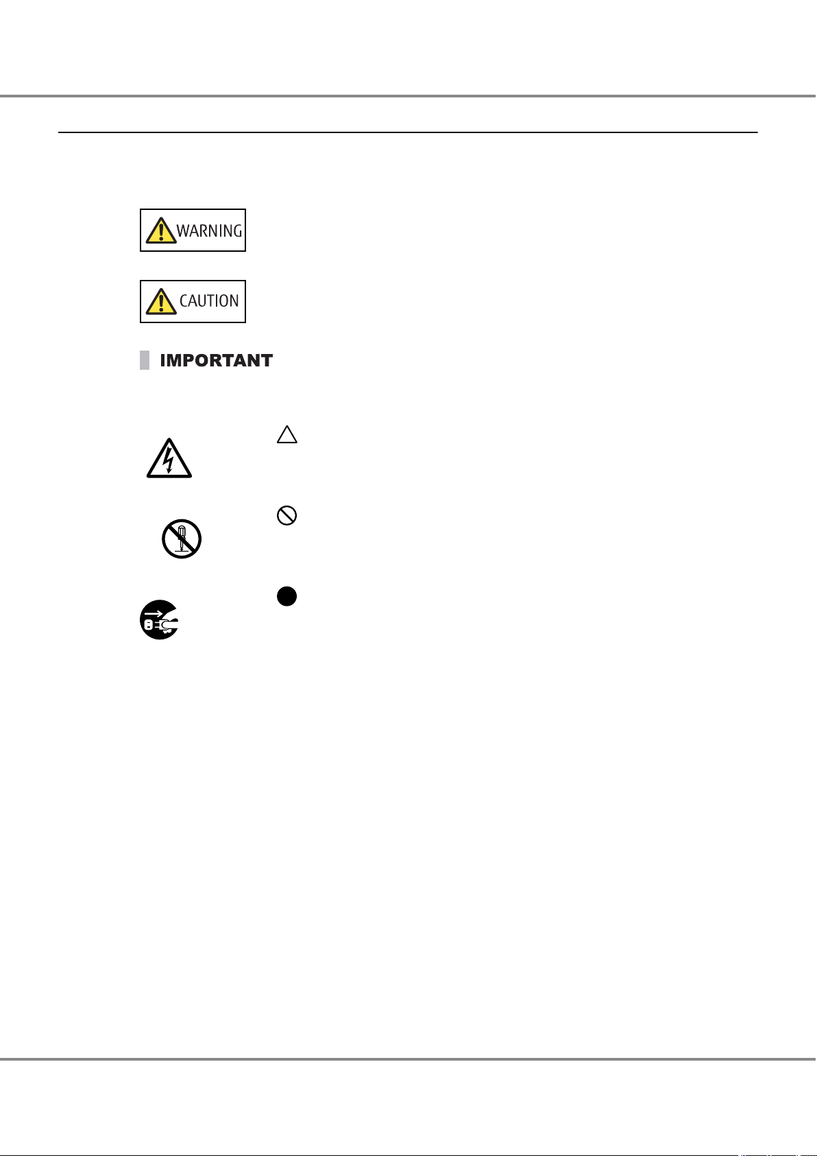
The following symbols are used to indicate the type of warnings or cautions being described.
This symbol indicates the possibility of serious or fatal injury if the ETERNUS AF is not
used properly.
This symbol indicates the possibility of minor or moderate personal injury, as well as
damage to the ETERNUS AF and/or to other users and their property, if the ETERNUS AF
is not used properly.
This symbol indicates IMPORTANT information for the user to note when using the ETER-
.
NUS AF
The triangle emphasizes the urgency of the WARNING and CAUTION contents. Inside
the triangle and above it are details concerning the symbol (e.g. Electrical Shock).
The barred "Do Not..." circle warns against certain actions. The action which must be
avoided is both illustrated inside the barred circle and written above it (e.g. No Disassembly).
The black "Must Do..." circle indicates actions that must be taken. The required action is both illustrated inside the black disk and written above it (e.g. Unplug).
6
FUJITSU Storage ETERNUS AF250 S2, ETERNUS AF250 All-Flash Arrays
Copyright 2017 FUJITSU LIMITED
Configuration Guide (Basic)
P3AG-1832-04ENZ0
Page 7
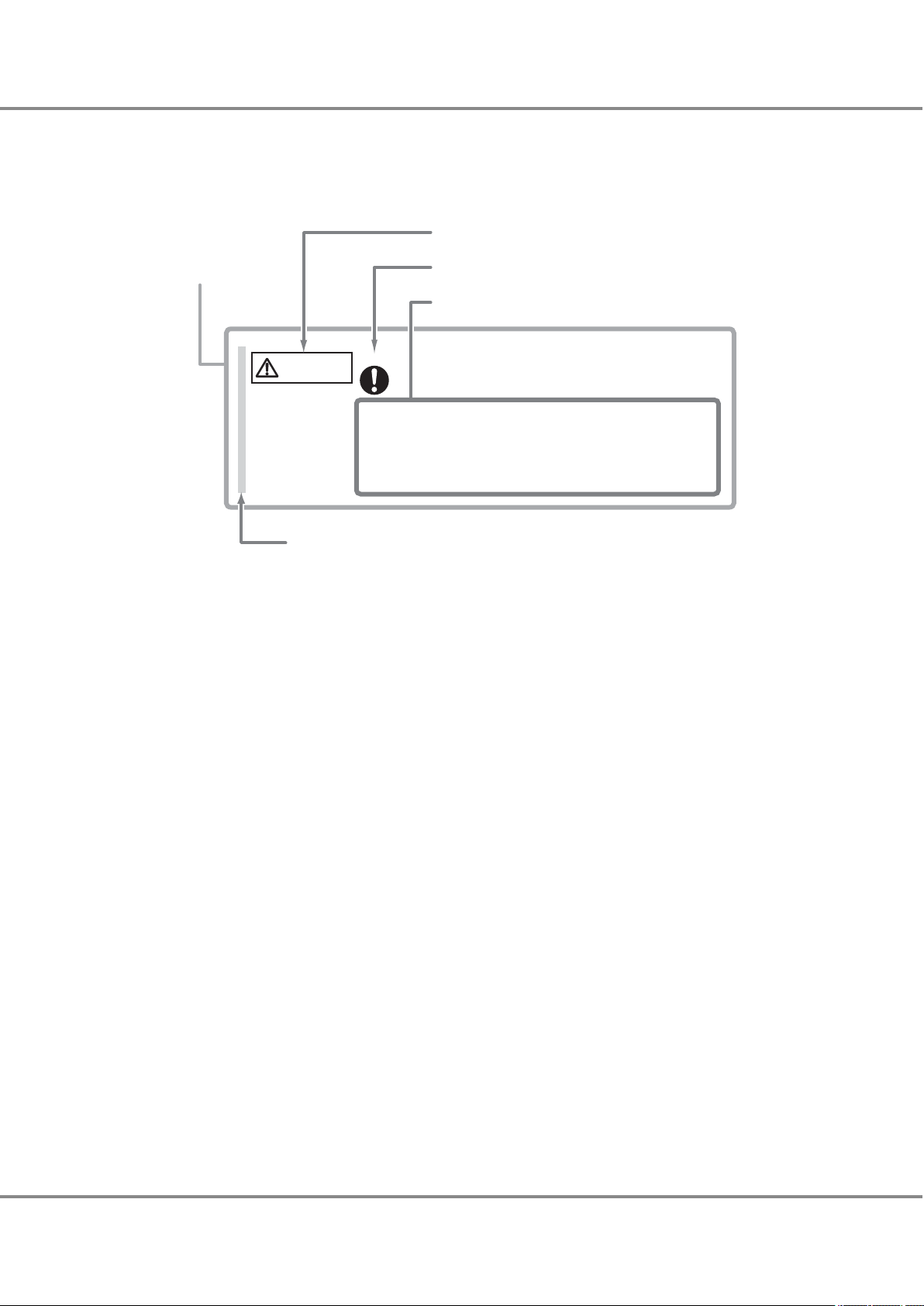
Warning level indicator
Warning type indicator
Warning details
To avoid damaging the ETERNUS storage system, pay attention to the
following points when cleaning the ETERNUS storage system:
- Make sure to disconnect the power when cleaning.
- Be careful that no liquid seeps into the ETERNUS storage system
when using cleaners, etc.
- Do not use alcohol or other solvents to clean the ETERNUS storage system.
Warning layout ribbon
Example warning
CAUTION
Do
Preface
How Warnings are Presented in This Manual
A message is written beside the symbol indicating the caution level. This message is marked with a vertical
ribbon in the left margin, to distinguish this warning from ordinary descriptions.
A display example is shown here.
7
FUJITSU Storage ETERNUS AF250 S2, ETERNUS AF250 All-Flash Arrays
Copyright 2017 FUJITSU LIMITED
Configuration Guide (Basic)
P3AG-1832-04ENZ0
Page 8
Manufacturer’s label
The model name and
the serial number are
listed.
Device ID label
The model name and the serial number
are listed.
Preface
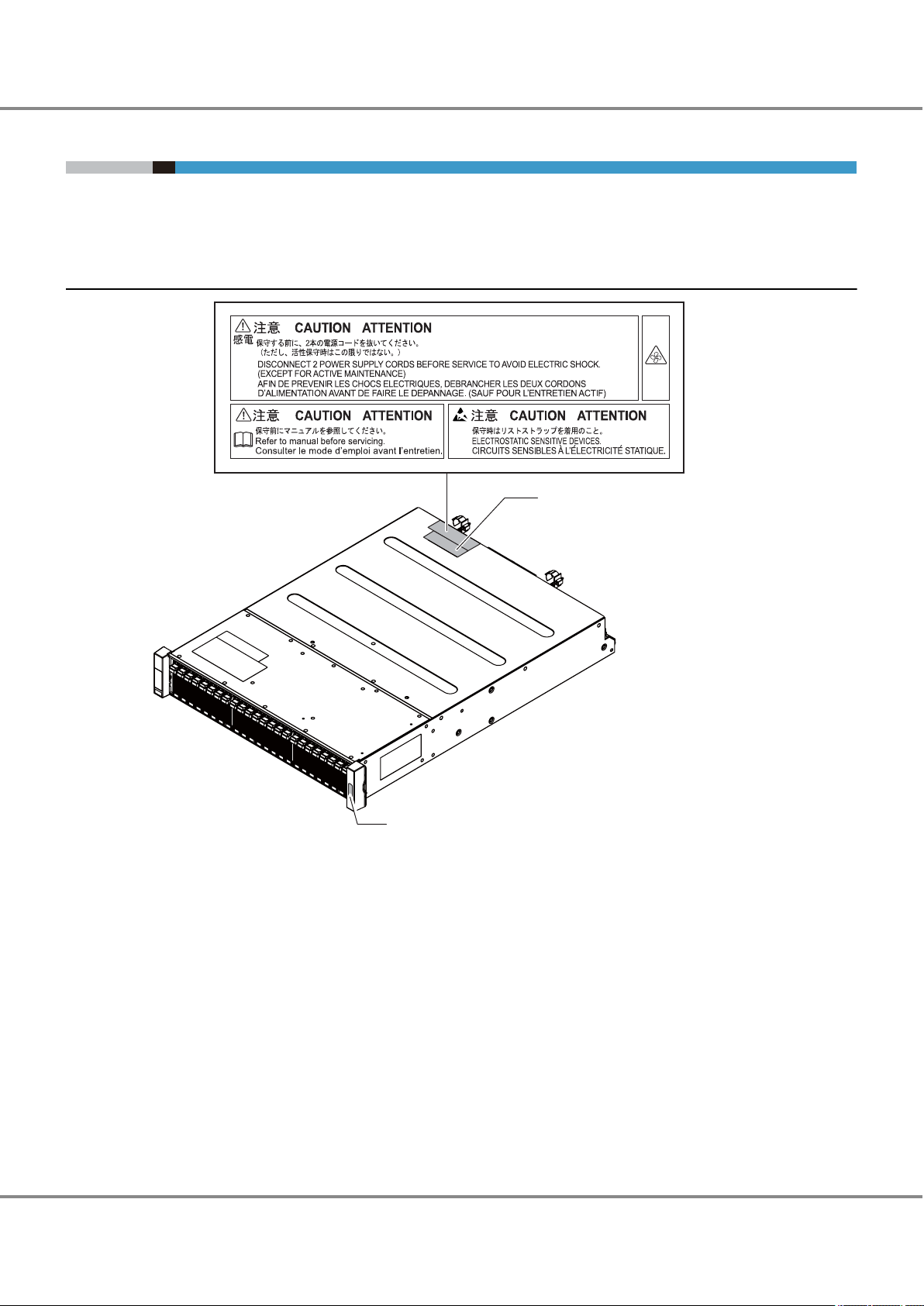
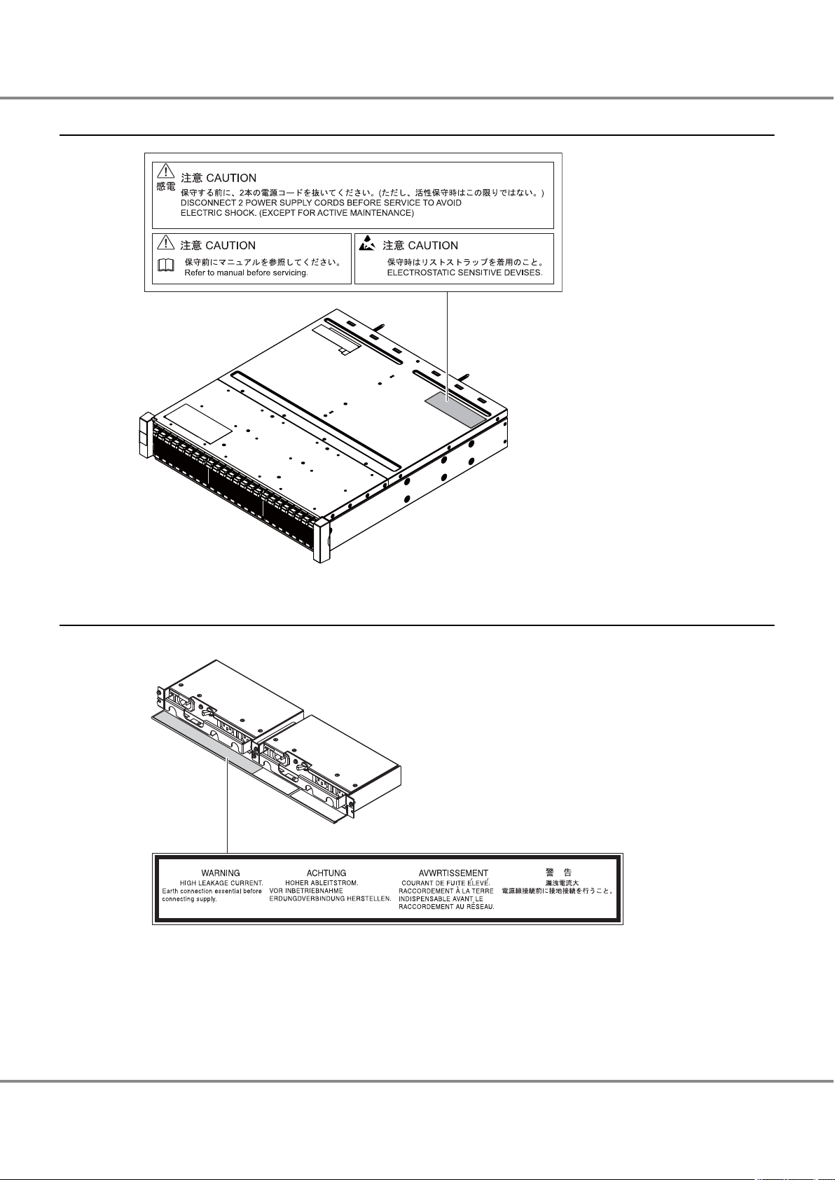
Warning Labels and Manufacturer's Labels
Warning labels, manufacturer's labels, and a device ID label are found in the ETERNUS AF, as shown in the
example below.
Never remove these labels from the equipment or allow them to become dirty.
Controller Enclosure
8
FUJITSU Storage ETERNUS AF250 S2, ETERNUS AF250 All-Flash Arrays
Copyright 2017 FUJITSU LIMITED
Configuration Guide (Basic)
P3AG-1832-04ENZ0
Page 9
Preface
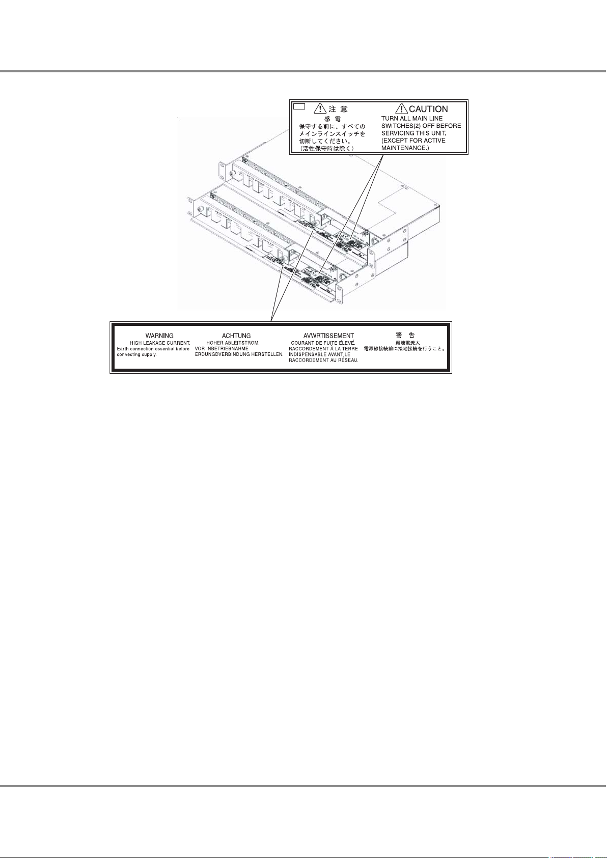
Drive Enclosures
Power Distribution Units (for Regions other than the EMEIA, Central American, and Caribbean Regions)
Power distribution unit (AC200-240V, 1U)
•
9
FUJITSU Storage ETERNUS AF250 S2, ETERNUS AF250 All-Flash Arrays
Copyright 2017 FUJITSU LIMITED
Configuration Guide (Basic)
P3AG-1832-04ENZ0
Page 10
Preface
Power distribution unit (AC200-240V, 2U)
•
10
FUJITSU Storage ETERNUS AF250 S2, ETERNUS AF250 All-Flash Arrays
Copyright 2017 FUJITSU LIMITED
Configuration Guide (Basic)
P3AG-1832-04ENZ0
Page 11

Table of Contents
Chapter 1 Component Names 17
1.1 Controller Enclosure ..................................................................................................................... 17
Front...................................................................................................................................................................17
1.1.1
1.1.2 Rear ....................................................................................................................................................................18
1.2 Drive Enclosures ........................................................................................................................... 18
1.2.1 Front...................................................................................................................................................................19
1.2.2 Rear ....................................................................................................................................................................19
1.3 Power Distribution Units (for Regions other than the EMEIA, Central American, and Caribbean Re-
gions) ........................................................................................................................................... 20
1.3.1 Power Distribution Units (1U).............................................................................................................................20
1.3.2 Power Distribution Units (2U).............................................................................................................................20
Chapter 2 Rack Installation 22
2.1 Power Distribution Unit Installation (for Regions other than the EMEIA, Central American, and Caribbean Regions)
2.1.1 Installing Power Distribution Unit (1U)...............................................................................................................24
2.1.2 Installing Power Distribution Unit (2U)...............................................................................................................26
........................................................................................................................... 23
2.2 Controller Enclosure Installation (for Regions other than the EMEIA, Central American, and Carib-
bean Regions) .............................................................................................................................. 28
2.3 Drive Enclosure Installation (for Regions other than the EMEIA, Central American, and Caribbean
Regions) ....................................................................................................................................... 31
Chapter 3 Checking the Configuration Environment 34
3.1 System Configuration Example..................................................................................................... 34
3.2 Server Connection Preparation
3.2.1 Driver Preparation ..............................................................................................................................................35
3.2.2 Driver Installation ...............................................................................................................................................36
..................................................................................................... 35
3.2.3 iSCSI Initiator Parameter Settings .......................................................................................................................37
3.3 Preparing the PC Terminal for Setup............................................................................................. 40
3.4 LAN Connection Preparation for Operation Management............................................................. 41
3.4.1 Completing and Attaching the Network Setting Label ........................................................................................41
3.4.2 LAN Related Specifications..................................................................................................................................42
11
FUJITSU Storage ETERNUS AF250 S2, ETERNUS AF250 All-Flash Arrays
Copyright 2017 FUJITSU LIMITED
Configuration Guide (Basic)
P3AG-1832-04ENZ0
Page 12

Table of Contents
Chapter 4 Connecting Cables 44
4.1 Host Interface Cable Connection................................................................................................... 44
4.2 Drive Enclosure Connection
.......................................................................................................... 47
4.3 Power Synchronized Unit Connection ........................................................................................... 49
4.4 Power Cord Connection................................................................................................................. 49
4.4.1 When No Power Distribution Units Are Installed.................................................................................................50
4.4.2 When 1U Power Distribution Unit Is Installed (for Regions other than the EMEIA, Central American, and Carib-
bean Regions).......................................................................................................................................................51
4.4.3 When 2U Power Distribution Unit Is Installed (for Regions other than the EMEIA, Central American, and Carib-
bean Regions).......................................................................................................................................................52
Chapter 5 General Settings 55
5.1 PC Terminal Connection................................................................................................................ 58
5.2
Powering On................................................................................................................................. 59
5.2.1 Switching On and Off the Main Line Switch on the Power Distribution Unit........................................................59
5.2.2 Switching On and Off the PSU Switch on the Power Supply Unit .........................................................................60
5.2.3 Powering On .......................................................................................................................................................61
5.3 ETERNUS Web GUI Startup ............................................................................................................ 62
5.4 Storage Management (Initial Setup 1)......................................................................................... 64
5.5 LAN Cable Connection (for Operation Management).................................................................... 70
5.6 Firewall Settings........................................................................................................................... 72
5.7 RAID Configuration Settings ......................................................................................................... 74
5.7.1 RAID Group Creation ...........................................................................................................................................74
5.7.2 Operation Volume Creation.................................................................................................................................76
5.7.3 Generation Management Volume (SDV) Creation...............................................................................................79
5.7.4 Copy Data Destination Volume (SDPV) Creation .................................................................................................80
5.7.5 Hot Spare Registration........................................................................................................................................82
Chapter 6 Monitoring Settings 85
6.1 Event Notification Setup............................................................................................................... 85
6.2
Various Notification Settings ........................................................................................................ 86
6.2.1 SNMP Trap Setup ................................................................................................................................................86
6.2.2 E-mail Setup .......................................................................................................................................................93
6.2.3 Syslog Setup .......................................................................................................................................................95
12
FUJITSU Storage ETERNUS AF250 S2, ETERNUS AF250 All-Flash Arrays
Copyright 2017 FUJITSU LIMITED
Configuration Guide (Basic)
P3AG-1832-04ENZ0
Page 13

Table of Contents
6.3 Remote Support Setup.................................................................................................................. 96
Remote Support (by AIS Connect) Setup .............................................................................................................97
6.3.1
6.3.2 Remote Support (by REMCS) Setup .....................................................................................................................98
6.4 Audit Log Setup.......................................................................................................................... 100
6.5 Monitoring Server (SNMP Manager) Settings ............................................................................. 101
6.6 Transmission Test Execution....................................................................................................... 102
6.6.1 SNMP Trap Test .................................................................................................................................................102
6.6.2 Send Test E-mail ...............................................................................................................................................103
Chapter 7 Power Control Setup 105
7.1 Setup of the Auto Power Function and/or the Power Resume Function ...................................... 105
7.2 Connection Setup for Power Synchronized Unit
.......................................................................... 107
7.3 Wake On LAN Settings................................................................................................................ 107
Chapter 8 SAN Connection Settings 109
8.1 Connection Settings for the ETERNUS AF .................................................................................... 109
8.1.1
Host Response Settings.....................................................................................................................................109
8.1.2 Host Affinity Settings ........................................................................................................................................110
8.1.3 CA Reset Group Settings....................................................................................................................................118
8.2 Server Connection Setup............................................................................................................. 119
8.2.1 iSCSI Initiator Parameter Settings (Connection Information Settings)...............................................................119
8.2.2 LUN Recognition Check.....................................................................................................................................128
8.2.3 Disk Partition Settings ......................................................................................................................................130
Chapter 9 Advanced Copy Settings 141
9.1 Advanced Copy Basic Settings .................................................................................................... 141
9.1.1 Copy Priority Settings........................................................................................................................................141
9.1.2 Copy Table Size Settings....................................................................................................................................143
9.1.3 Copy Parameter Settings ..................................................................................................................................145
9.2 Performing a Copy (SnapOPC+) .................................................................................................. 146
Chapter 10 System Status Check 152
10.1 Checking the Component Status............................................................................................... 152
10.2 Checking the RAID Groups
........................................................................................................ 153
13
FUJITSU Storage ETERNUS AF250 S2, ETERNUS AF250 All-Flash Arrays
Copyright 2017 FUJITSU LIMITED
Configuration Guide (Basic)
P3AG-1832-04ENZ0
Page 14

Table of Contents
10.3 Checking the Volumes.............................................................................................................. 154
10.4 Checking the Copy Sessions
...................................................................................................... 155
10.5 Checking the LUNs ................................................................................................................... 155
10.6 Powering Off ............................................................................................................................ 156
Chapter 11 Solution Configuration 158
11.1 Continuous Business ................................................................................................................ 158
11.1.1 Remote Copy Operations for the Storage System (Copies between ETERNUS AF
11.1.2 Automatic Switching Operation of the Storage Systems (Storage Cluster) ......................................................160
11.2 Performance/Tuning................................................................................................................. 162
11.3 Virtualization Platform ............................................................................................................. 164
11.3.1 Oracle VM Linkage ..........................................................................................................................................164
11.3.2 VMware Linkage .............................................................................................................................................165
11.3.3 Microsoft Linkage ...........................................................................................................................................167
11.4 Security .................................................................................................................................... 168
Storage Systems) ................158
14
FUJITSU Storage ETERNUS AF250 S2, ETERNUS AF250 All-Flash Arrays
Copyright 2017 FUJITSU LIMITED
Configuration Guide (Basic)
P3AG-1832-04ENZ0
Page 15

List of Figures
Figure 1.1 Front View of a Controller Enclosure.........................................................................................................17
Figure 1.2
Figure 1.3 Front View of a Drive Enclosure ................................................................................................................19
Figure 1.4 Rear View of a Drive Enclosure .................................................................................................................19
Figure 1.5 Power Distribution Unit (AC200-240V, 1U, 4 Outlets)...............................................................................20
Figure 1.6 Power Distribution Unit (AC200-240V, 2U, 12 Outlets).............................................................................20
Figure 1.7 Power Distribution Unit (AC200-240V, 2U, 16 Outlets).............................................................................21
Figure 3.1 System Configuration Example.................................................................................................................34
Figure 3.2 Network Setting Label..............................................................................................................................41
Figure 5.1 Example of Differential Backup Settings with SnapOPC+..........................................................................56
Figure 5.2 Example of Creating Operation Volume and Backup Volume ...................................................................57
Figure 5.3 PC Terminal Connection for Initial Setup ..................................................................................................58
Figure 5.4 ON Position (Marked "|") of the Main Line Switches on a 1U Power Distribution Unit ..............................59
Figure 5.5 ON Position (Marked "|") of the Main Line Switches on a 2U Power Distribution Unit ..............................59
Figure 5.6 ON Position (Marked "|") of the PSU Switch on a Power Supply Unit ........................................................60
Figure 5.7 RAID Group Creation.................................................................................................................................74
Figure 5.8 Operation Volume Creation ......................................................................................................................76
Figure 5.9 Generation Management Volume (SDV) Creation ....................................................................................79
Figure 5.10 Copy Data Destination Volume (SDPV) Creation.......................................................................................80
Figure 8.1 Connection Configuration with Servers...................................................................................................119
Figure 11.1 Solution — Continuous Business (Copy between ETERNUS AF storage systems)......................................158
Figure 11.2 Solution — Continuous Business (Storage Cluster) ..................................................................................160
Figure 11.3 Solution — Performance/Tuning ..............................................................................................................162
Figure 11.4 Solution — Virtualization Platform (Oracle VM Linkage)..........................................................................164
Figure 11.5 Solution — Virtualization Platform (VMware Linkage).............................................................................165
Figure 11.6 Solution — Virtualization Platform (Microsoft Linkage)...........................................................................167
Rear View of a Controller Enclosure ..........................................................................................................18
15
FUJITSU Storage ETERNUS AF250 S2, ETERNUS AF250 All-Flash Arrays
Copyright 2017 FUJITSU LIMITED
Configuration Guide (Basic)
P3AG-1832-04ENZ0
Page 16

List of Tables
Table 3.1 Server (Host) Environment.......................................................................................................................35
Table 3.2
Table 5.1 RAID Group Creation.................................................................................................................................74
Table 5.2 Operation Volume Creation ......................................................................................................................77
Table 7.1 ETERNUS AF Operation according to the Settings of the Auto Power Function and the Power Resume
LAN Port Availability.................................................................................................................................42
Function.................................................................................................................................................105
16
FUJITSU Storage ETERNUS AF250 S2, ETERNUS AF250 All-Flash Arrays
Copyright 2017 FUJITSU LIMITED
Configuration Guide (Basic)
P3AG-1832-04ENZ0
Page 17
Chapter 1
1
3 3
2
Component Names
This chapter provides the component names of the ETERNUS AF.
1.1 Controller Enclosure
An operation panel and drives are installed in the front of the ETERNUS AF (controller enclosure). Controllers
and power supply units are installed in the rear.
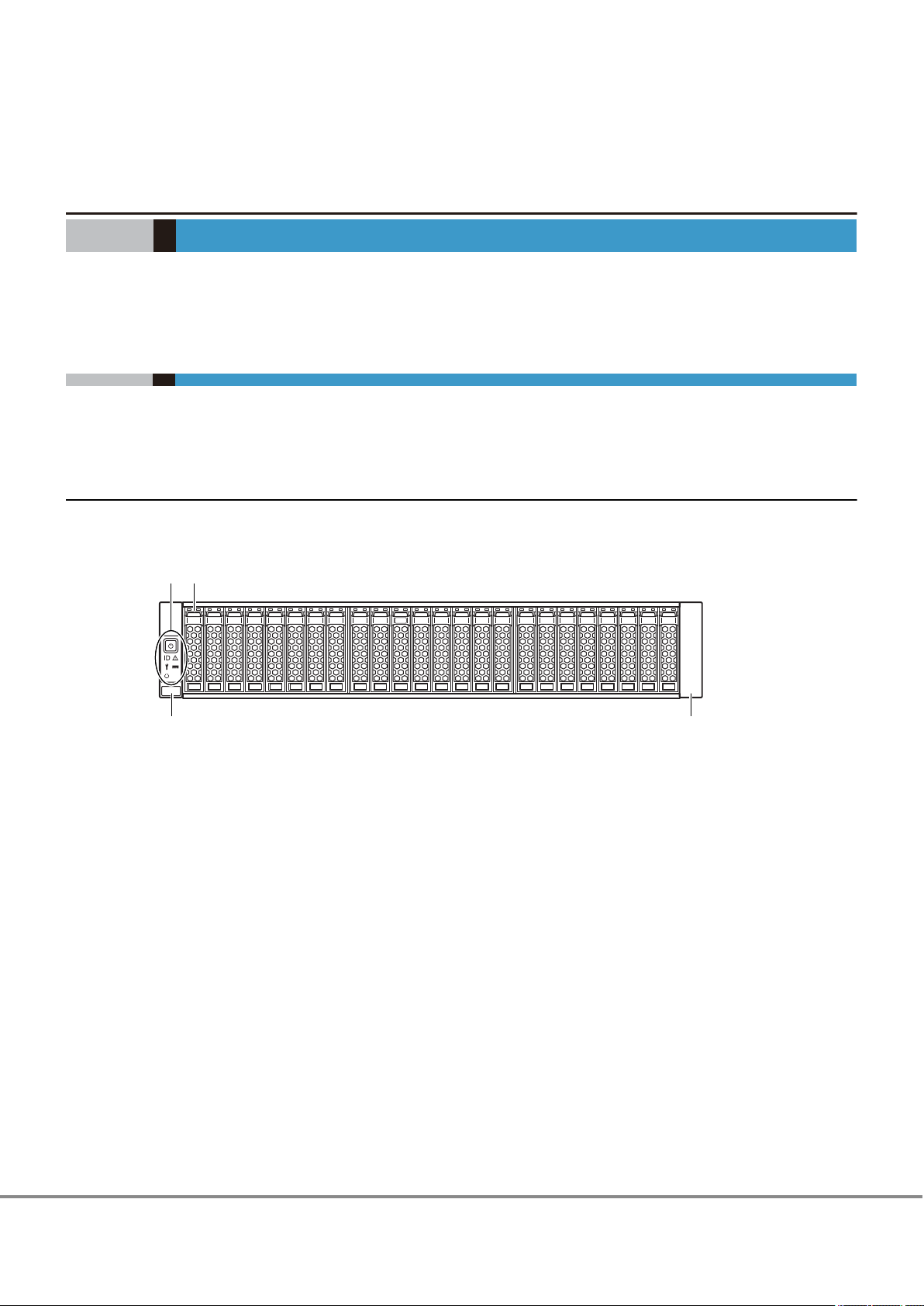
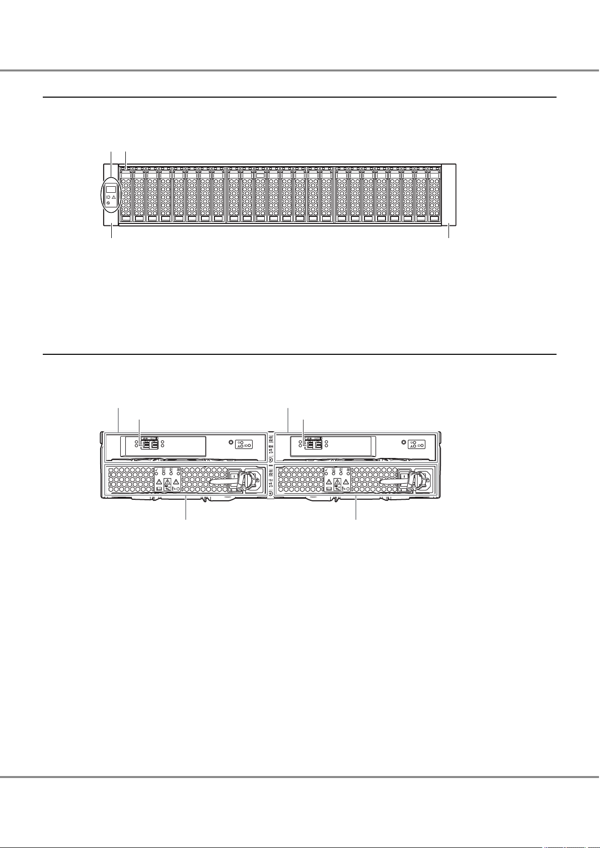
1.1.1 Front
This section provides the names of the components in the front of a controller enclosure.
Figure 1.1 Front View of a Controller Enclosure
1. Operation panel
2. Drive
3. Flange cover
17
FUJITSU Storage ETERNUS AF250 S2, ETERNUS AF250 All-Flash Arrays
Copyright 2017 FUJITSU LIMITED
Configuration Guide (Basic)
P3AG-1832-04ENZ0
Page 18
12
3567 6734 588
9 10
4
Chapter 1 Component Names
1.2 Drive Enclosures
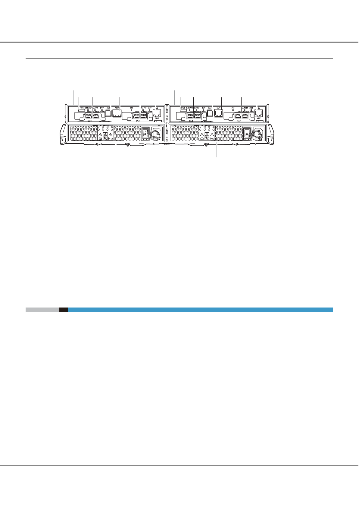
1.1.2 Rear
This section provides the names of the components in the rear of a controller enclosure.
Figure 1.2 Rear View of a Controller Enclosure
1. Controller (CM#0)
2. Controller (CM#1)
3. PWC port
4. Host interface (CA#0)
5. Drive interface (OUT) port
6. RMT (LAN) port
7. Host interface (CA#1)
8. MNT (LAN) port
9. Power supply unit (PSU#0)
10. Power supply unit (PSU#1)
1.2 Drive Enclosures
Drives and an operation panel are installed in the front of the drive enclosure. I/O modules and power supply
units are installed in the rear.
18
FUJITSU Storage ETERNUS AF250 S2, ETERNUS AF250 All-Flash Arrays
Copyright 2017 FUJITSU LIMITED
Configuration Guide (Basic)
P3AG-1832-04ENZ0
Page 19
1
3 3
2
3
12
45
3
Chapter 1 Component Names
1.2 Drive Enclosures
1.2.1 Front
This section provides the names of the components in the front of a drive enclosure.
Figure 1.3 Front View of a Drive Enclosure
1. Operation panel
2. Drive
3. Flange cover
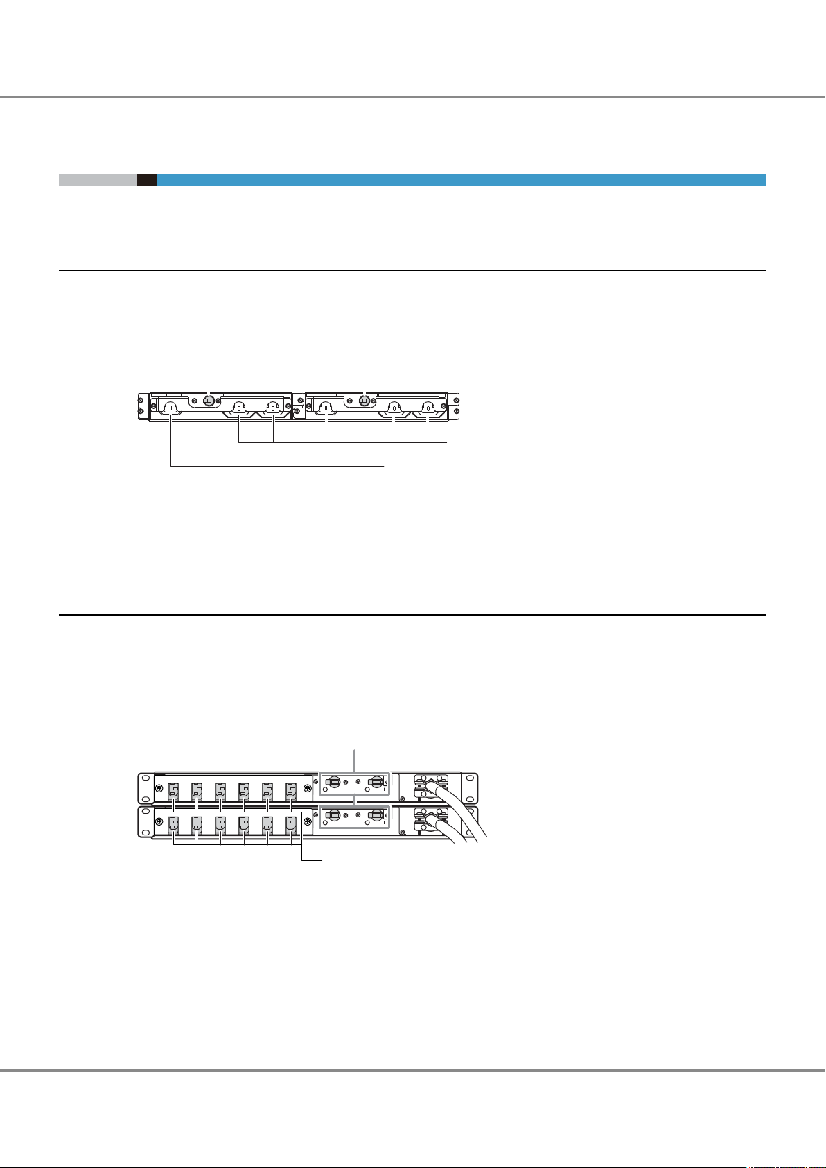
1.2.2 Rear
This section provides the names of the components in the rear of a drive enclosure.
Figure 1.4 Rear View of a Drive Enclosure
1. I/O module (IOM#0)
2. I/O module (IOM#1)
3. Drive interface (IN) port
4. Power supply unit (PSU#0)
5. Power supply unit (PSU#1)
19
FUJITSU Storage ETERNUS AF250 S2, ETERNUS AF250 All-Flash Arrays
Copyright 2017 FUJITSU LIMITED
Configuration Guide (Basic)
P3AG-1832-04ENZ0
Page 20
3
2
1
2
1
Chapter 1 Component Names
1.3 Power Distribution Units (for Regions other than the EMEIA, Central American, and Caribbean Regions)
1.3 Power Distribution Units (for Regions other than the EMEIA,
Central American, and Caribbean Regions)
There are two sizes for power distribution units: 1U and 2U.
1.3.1 Power Distribution Units (1U)
The 1U power distribution unit has four outlets and two inlets.
1.3.1.1 Power Distribution Unit (AC200-240V, 1U, 4 Outlets)
Figure 1.5 Power Distribution Unit (AC200-240V, 1U, 4 Outlets)
1. Main line switch
2. Outlet (OUTPUT)
3. Inlet (INPUT)
1.3.2 Power Distribution Units (2U)
2U power distribution units are available in two types: a 12 outlet type and a 16 outlet type.
1.3.2.1 Power Distribution Unit (AC200-240V, 2U, 12 Outlets)
There are 12 outlets.
Figure 1.6
1. Main line switch
Power Distribution Unit (AC200-240V, 2U, 12 Outlets)
2. Outlet (OUTPUT)
FUJITSU Storage ETERNUS AF250 S2, ETERNUS AF250 All-Flash Arrays
20
Configuration Guide (Basic)
Copyright 2017 FUJITSU LIMITED
P3AG-1832-04ENZ0
Page 21

2
1
Chapter 1 Component Names
1.3 Power Distribution Units (for Regions other than the EMEIA, Central American, and Caribbean Regions)
1.3.2.2 Power Distribution Unit (AC200-240V, 2U, 16 Outlets)
There are 16 outlets.
Figure 1.7
1. Main line switch
2. Outlet (OUTPUT)
Power Distribution Unit (AC200-240V, 2U, 16 Outlets)
21
FUJITSU Storage ETERNUS AF250 S2, ETERNUS AF250 All-Flash Arrays
Copyright 2017 FUJITSU LIMITED
Configuration Guide (Basic)
P3AG-1832-04ENZ0
Page 22
Chapter 2
Do
Do Not
Rack Installation
This chapter describes the procedure for installing the ETERNUS AF in a rack.
Make sure to check "Safety Precautions" before starting the installation. Also refer to the rack manual.
Wear a wrist strap or touch a metal part to discharge the human body's natural
•
static electricity before starting each operation. Failure to discharge static electricity may cause failure in the
If components are installed in a way other as described in this chapter, damage
•
and/or device failure or electrical shock may occur.
Do not install the ETERNUS AF in the rack with cables, such as power cords, connec-
•
ted.
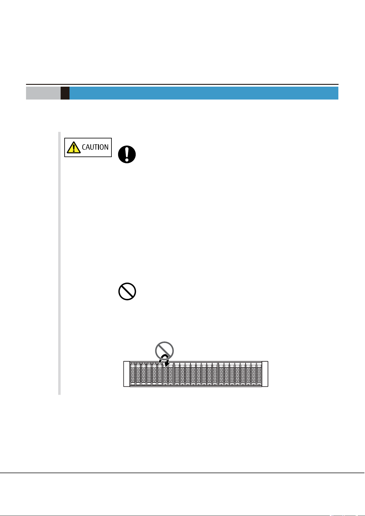
The ETERNUS AF contains delicate components, and should be handled gently. Do
•
not drop or knock the ETERNUS AF against the rack when installing it. Also, do not
knock the other devices installed in the rack.
The center of gravity must be taken into consideration to prevent a rack from top-
•
pling over. Enclosures should generally be installed from bottom to top to lower
the center of gravity and to ensure the safe use of racks.
ETERNUS AF.
Do not uninstall the drives that are installed by default or move them to any other
•
slot.
Contact your sales representative or maintenance engineer if drives that are installed by default need to be uninstalled or moved to another slot.
22
FUJITSU Storage ETERNUS AF250 S2, ETERNUS AF250 All-Flash Arrays
Copyright 2017 FUJITSU LIMITED
Configuration Guide (Basic)
P3AG-1832-04ENZ0
Page 23
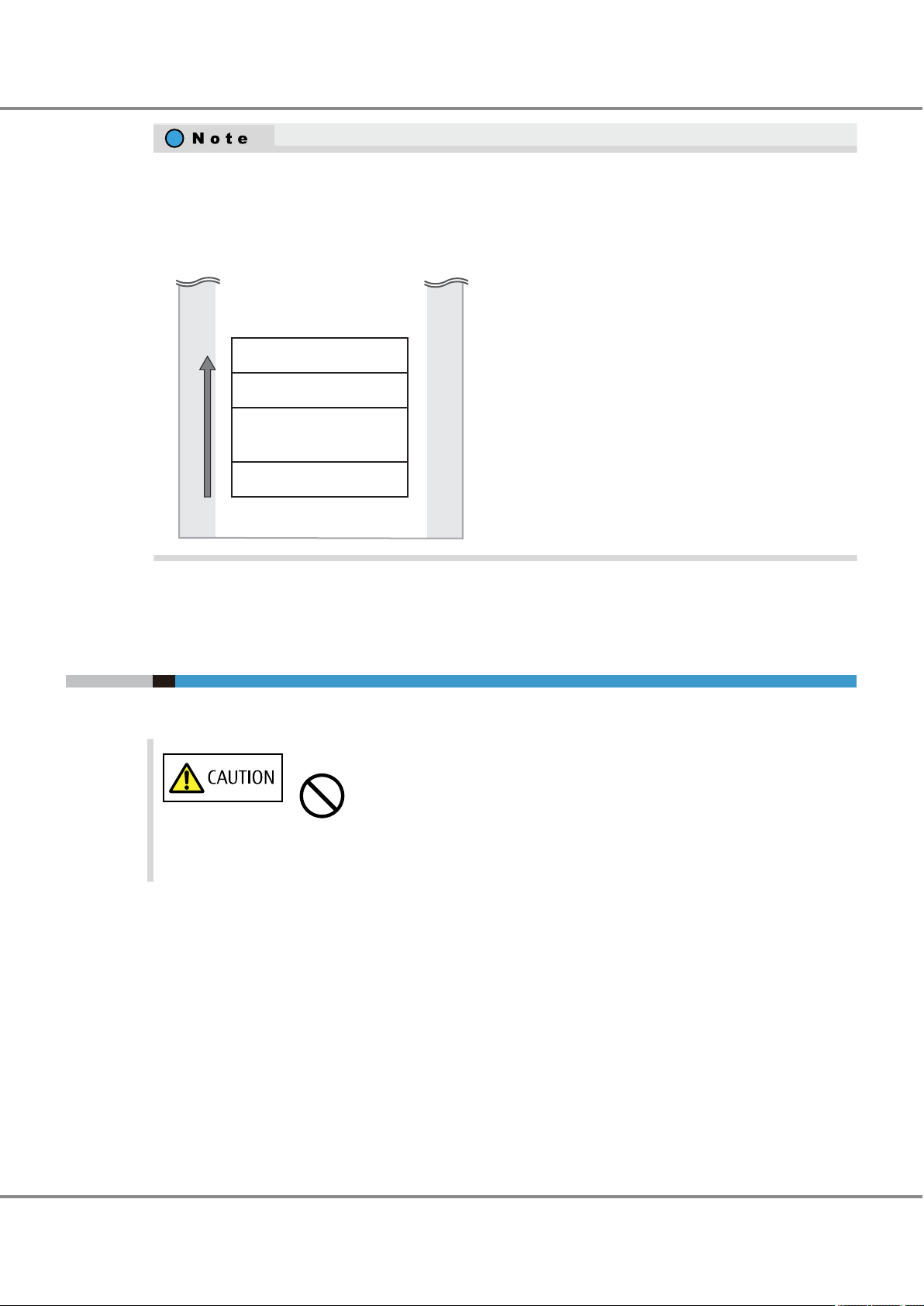
Rack
Controller enclosure
Power distribution unit/
Power synchronized unit
Drive enclosure
UPS
1
2
3
4
Installation
order
Do Not
Chapter 2 Rack Installation
2.1 Power Distribution Unit Installation (for Regions other than the EMEIA, Central American, and Caribbean Regions)
If the storage system is installed at the bottom of a rack, a space for the surplus of cables may not be
•
available in some racks, preventing the storage system from being pulled out when maintenance work
is required. In this case, secure a space of 1U or more at the bottom when installing the storage system.
To install an enclosure, power distribution units, power synchronized units, and UPS units in a single
•
rack, mount the devices in the following order (from bottom to top).
2.1 Power Distribution Unit Installation (for Regions other than
the EMEIA, Central American, and Caribbean Regions)
This section describes how to install the power distribution unit in a rack.
Do not connect any devices other than the
•
unit.
ETERNUS AF to the power distribution
23
FUJITSU Storage ETERNUS AF250 S2, ETERNUS AF250 All-Flash Arrays
Copyright 2017 FUJITSU LIMITED
Configuration Guide (Basic)
P3AG-1832-04ENZ0
Page 24
Power distribution unit
Bracket B
Bracket A
M3 screw
M3 screw
(Rack pillar: rear)
Bracket B
Screw
holder
M6 screw
Screw
holder
Bracket A
Holder
Holder
M6 screw
Power distribution unit1U
(Rack pillar: rear)
Bracket
Power distribution unit
base line
1st hole
(M6 screw)
3rd hole
(M6 screw)
1st hole
(M6 screw)
3rd hole
(M6 screw)
[Left] [Right]
Chapter 2 Rack Installation
2.1 Power Distribution Unit Installation (for Regions other than the EMEIA, Central American, and Caribbean Regions)
2.1.1 Installing Power Distribution Unit (1U)
This section describes how to install the 1U power distribution unit in a rack.
1 Remove the two brackets temporarily attached to the power distribution unit.
Remove the two M3 screws from the front of the power distribution unit to free the brackets.
2 Attach the brackets and holders to the rack.
The four M6 screw positions for the brackets are determined relative to the power distribution unit base
line.
The four M6 screws should be inserted in the 1st and 3rd holes above the base line.
FUJITSU Storage ETERNUS AF250 S2, ETERNUS AF250 All-Flash Arrays
24
Configuration Guide (Basic)
Copyright 2017 FUJITSU LIMITED
P3AG-1832-04ENZ0
Page 25
(Rack pillar: rear)
M3 screw
M3 screw
(Rack pillar: rear)
(Rack pillar: front)
Blank panel
Power distribution unit
Chapter 2 Rack Installation
2.1 Power Distribution Unit Installation (for Regions other than the EMEIA, Central American, and Caribbean Regions)
3 Install the power distribution unit in the rack.
Fasten the power distribution unit to the bracket with the two M3 screws removed in Step 1.
4 Attach the blank panel to the front side of the rack.
The blank panel should be attached at the same height as the power distribution unit.
25
FUJITSU Storage ETERNUS AF250 S2, ETERNUS AF250 All-Flash Arrays
Copyright 2017 FUJITSU LIMITED
Configuration Guide (Basic)
P3AG-1832-04ENZ0
Page 26
1U
1U
2U
Power distribution unit
Power distribution unit
(Rack pillar: rear)
Power distribution unit
base line
M5 cage nut M5 cage nut
1st hole
3rd hole
4th hole
6th hole
1st hole
3rd hole
4th hole
6th hole
[Left] [Right]
Side view
M5 cage nut
Rack pillar (square hole)
Chapter 2 Rack Installation
2.1 Power Distribution Unit Installation (for Regions other than the EMEIA, Central American, and Caribbean Regions)
2.1.2 Installing Power Distribution Unit (2U)
This section explains how to install a 2U power distribution unit (12 outlet type or 16 outlet type) in a rack.
This section explains how to install a 12 outlet type power distribution unit as an example. This installation method can also be applied to a 16 outlet type power distribution unit.
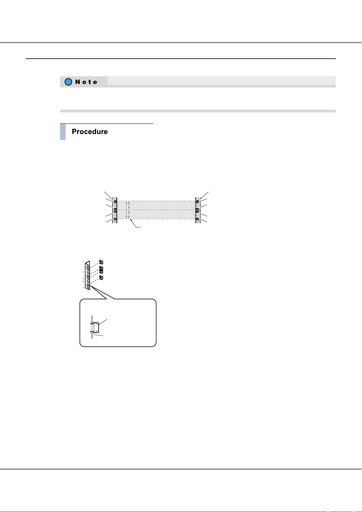
1 Attach the M5 cage nuts to the rear rack pillar.
• Attachment positions
On either side, insert eight M5 cage nuts in the 1st, 3rd, 4th, and 6th holes above the power distribution unit base line.
• Attachment procedure
Clip the M5 cage nut tabs into the desired hole from the inside.
FUJITSU Storage ETERNUS AF250 S2, ETERNUS AF250 All-Flash Arrays
26
Configuration Guide (Basic)
Copyright 2017 FUJITSU LIMITED
P3AG-1832-04ENZ0
Page 27
(Rack pillar: rear)
M5 screw
M5 screw
(Rack pillar: rear)
(Rack pillar: front)
Blank panel
Power distribution unit
Chapter 2 Rack Installation
2.1 Power Distribution Unit Installation (for Regions other than the EMEIA, Central American, and Caribbean Regions)
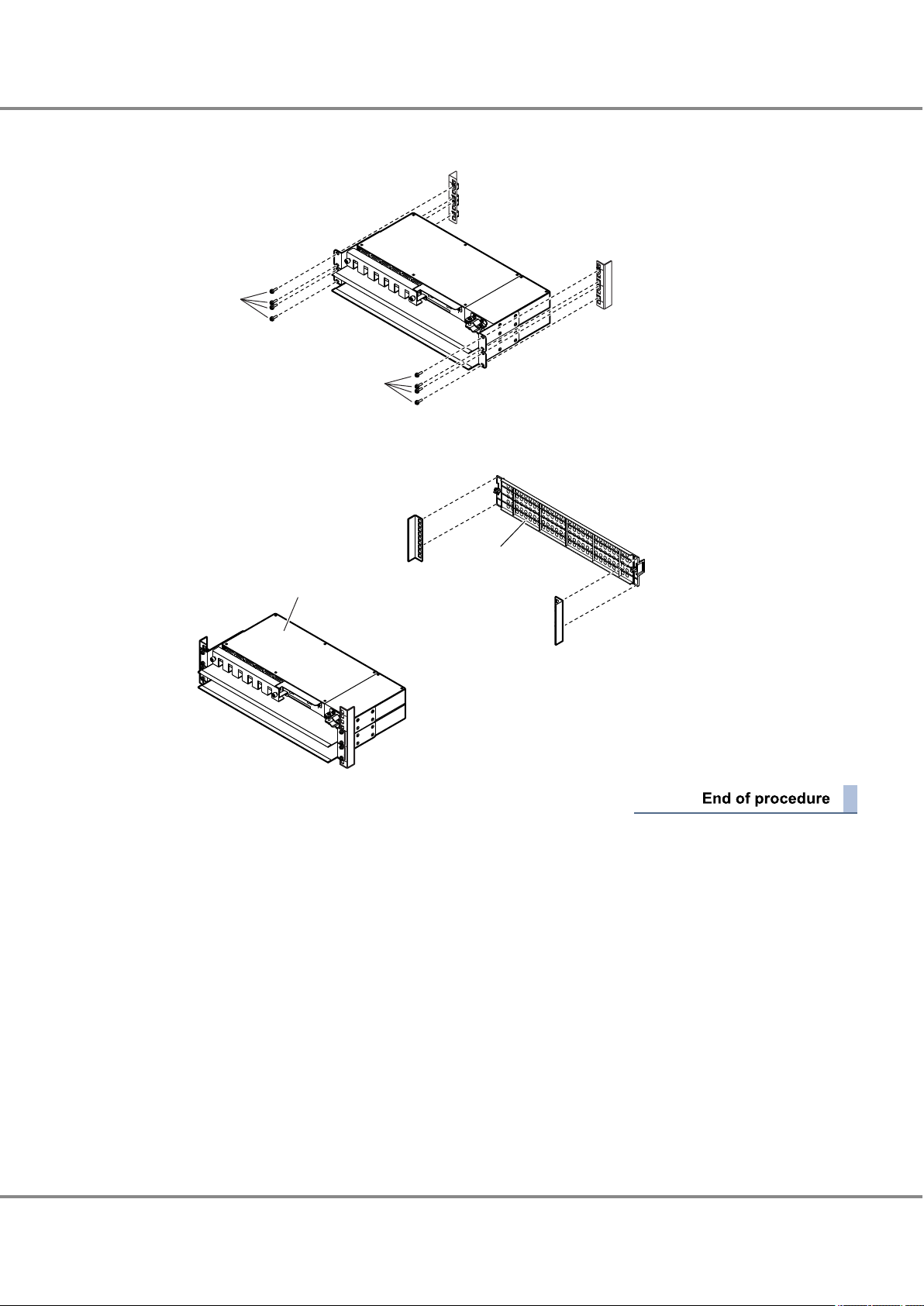
2 Install the power distribution unit in the rack.
Fasten it to the prepared holes in the pillars with eight M5 screws.
3 Attach the blank panel to the rack front.
The blank panel should be attached at the same height as the power distribution unit.
27
FUJITSU Storage ETERNUS AF250 S2, ETERNUS AF250 All-Flash Arrays
Copyright 2017 FUJITSU LIMITED
Configuration Guide (Basic)
P3AG-1832-04ENZ0
Page 28
Loosen the M4 screws to
adjust the length of the
rack rails to match the
distance between the
front and rear rack pillars.
(Rack pillar: front)
(Rack pillar: rear)
Rack rail (right)
An "R" mark is on the inner side.
[Left]
[Right]
Rack rail (left)
An "L" mark is on the
inner side.
Chapter 2 Rack Installation
2.2 Controller Enclosure Installation (for Regions other than the EMEIA, Central American, and Caribbean Regions)
2.2 Controller Enclosure Installation (for Regions other than the
EMEIA, Central American, and Caribbean Regions)
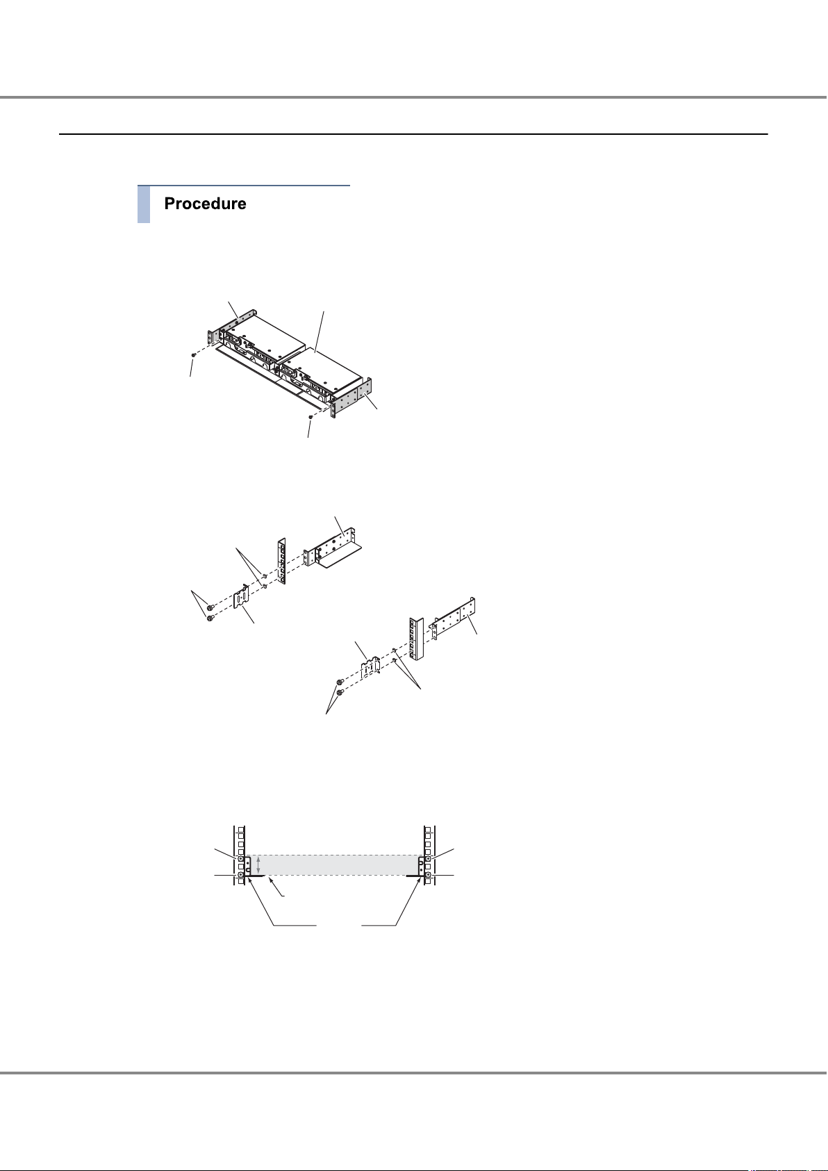
This section describes how to install the controller enclosure in a rack.
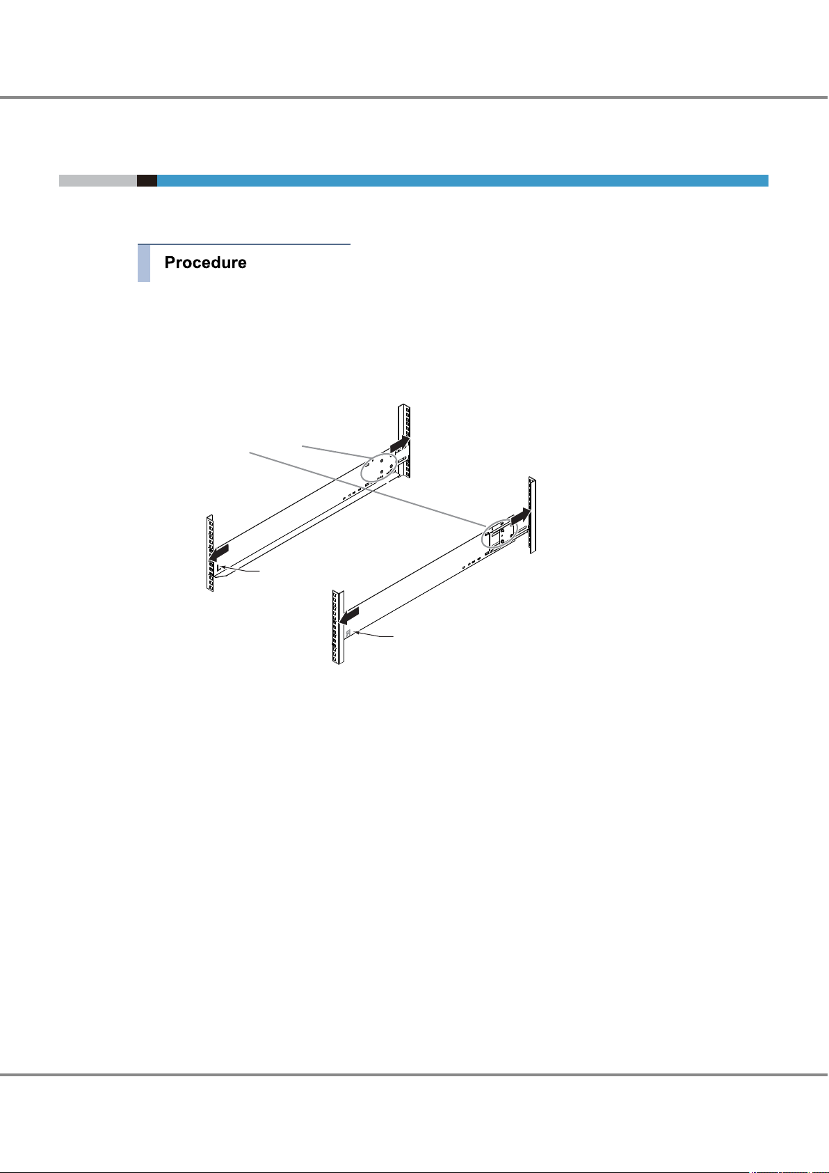
1 Adjust the sizes of the rack rail (for left side) and the rack rail (for right side) to fit the rack.
Loosen the M4 screws to adjust the length of the rack rails to match the distance between the front and
rear rack pillars. Leave the M4 screws slightly unscrewed, as the rack rails must be attached to the rack
before they can be completely tightened.
2 Attach the rack rails to the rack.
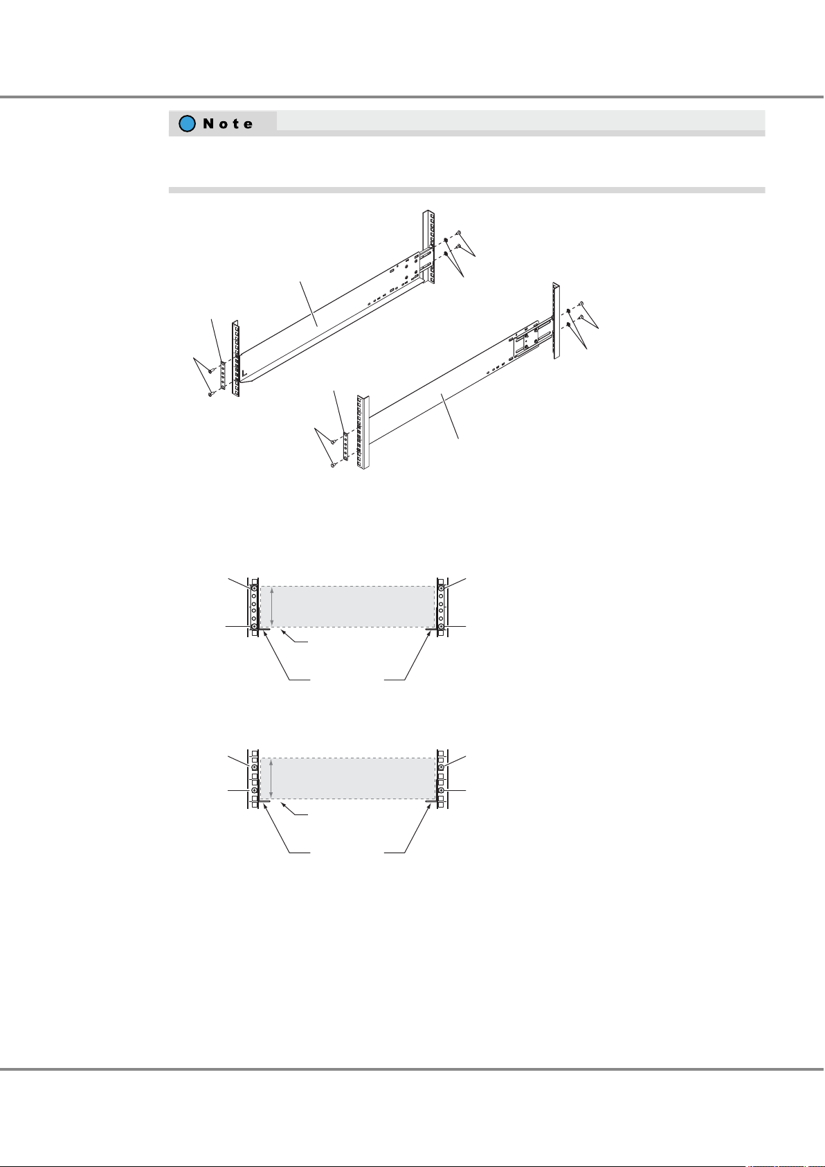
Use the two plates to fasten the rack rails to the front rack pillars. Use the washers to fasten the rack
rails to the rear rack pillars.
28
Configuration Guide (Basic)
FUJITSU Storage ETERNUS AF250 S2, ETERNUS AF250 All-Flash Arrays
Copyright 2017 FUJITSU LIMITED
P3AG-1832-04ENZ0
Page 29
(Rack pillar: front)
(Rack pillar: rear)
Washer
M5 screw
M5 screw
Washer
M5 screw
Plate
M5 screw
Plate
Rack rail (right)
Rack rail (left)
Controller enclosure: front
Controller enclosure: rear
2U
Rack rail
Controller
enclosure base line
Rack rail
Controller
enclosure base line
[Right]
[Left]
6th hole
(M5 screw)
1st hole
(M5 screw)
6th hole
(M5 screw)
1st hole
(M5 screw)
2U
[Right][Left]
5th hole
(M5 screw)
2nd hole
(M5 screw)
5th hole
(M5 screw)
2nd hole
(M5 screw)
Chapter 2 Rack Installation
2.2 Controller Enclosure Installation (for Regions other than the EMEIA, Central American, and Caribbean Regions)
Make sure to attach the rack rails to rack pillars so that they fit exactly together without any space
between them.
3 Tighten the M4 screws of the rack rails that were slightly unscrewed in Step 1.
The M5 screw positions for the rack rails are determined by the controller enclosure base line.
Insert the M5 screws in the 1st and 6th holes on the front rack pillars above the base line and in the
2nd and 5th holes on the rear rack pillars above the base line to fasten the rack rails.
FUJITSU Storage ETERNUS AF250 S2, ETERNUS AF250 All-Flash Arrays
29
Configuration Guide (Basic)
Copyright 2017 FUJITSU LIMITED
P3AG-1832-04ENZ0
Page 30
Do
M5 screw
M5 screws
Chapter 2 Rack Installation
2.2 Controller Enclosure Installation (for Regions other than the EMEIA, Central American, and Caribbean Regions)
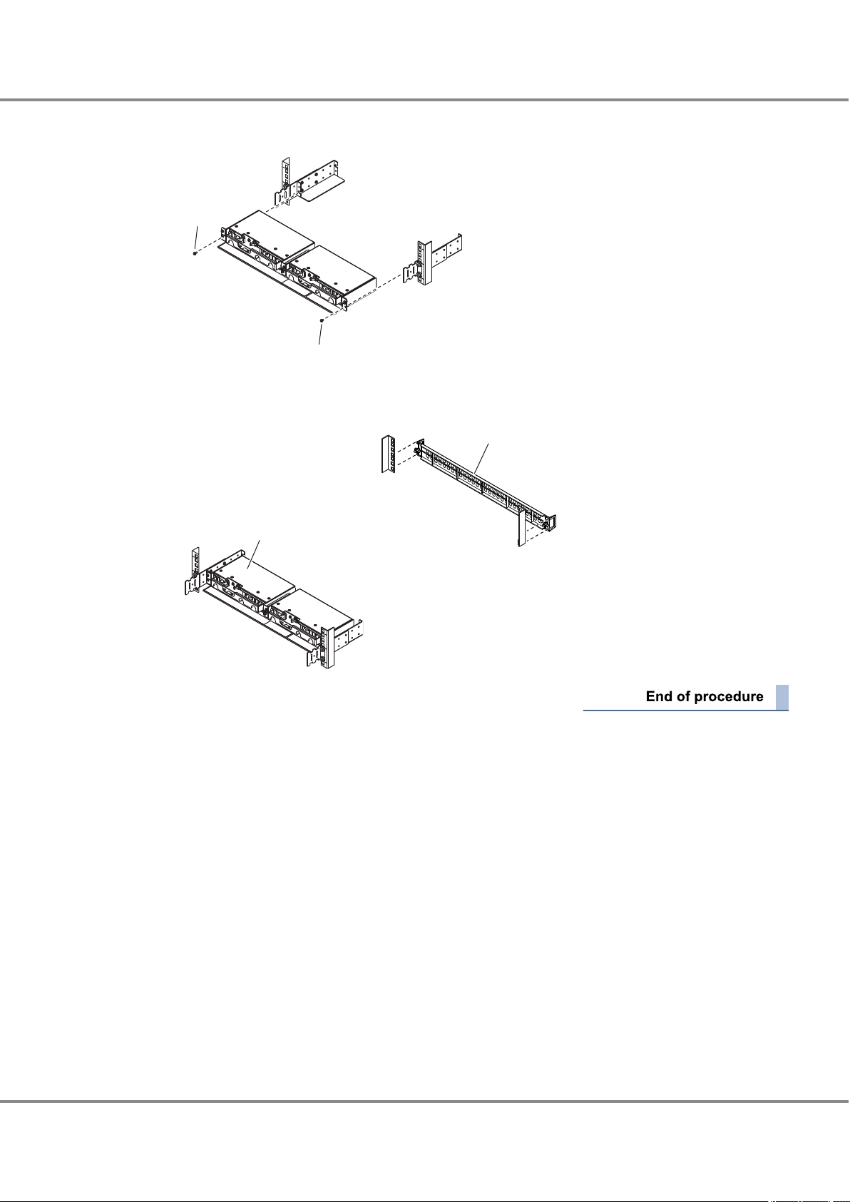
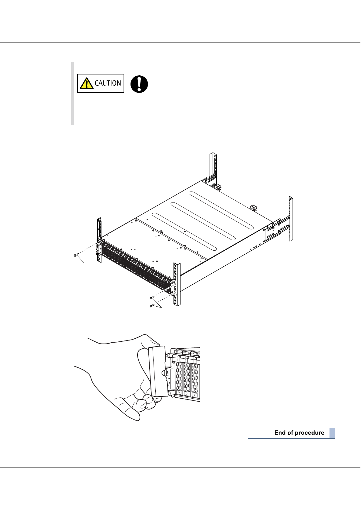
4 Install the controller enclosure in the rack.
• When installing or removing the controller enclosure to or from the rack,
make sure that the sides and the bottom of the controller enclosure are held
by two or more people. Failure to do so may cause injury.
5 Fasten the controller enclosure in the rack.
Use three M5 screws to fasten it in the rack pillar.
6 Attach the flange cover.
FUJITSU Storage ETERNUS AF250 S2, ETERNUS AF250 All-Flash Arrays
30
Configuration Guide (Basic)
Copyright 2017 FUJITSU LIMITED
P3AG-1832-04ENZ0
Page 31

Loosen the M4 screws to
adjust the length of the
rack rails to match the
distance between the
front and rear rack pillars.
(Rack pillar: front)
(Rack pillar: rear)
Rack rail (right)
An "R" mark is on the inner side.
[Left]
[Right]
Rack rail (left)
An "L" mark is on the
inner side.
Chapter 2 Rack Installation
2.3 Drive Enclosure Installation (for Regions other than the EMEIA, Central American, and Caribbean Regions)
2.3 Drive Enclosure Installation (for Regions other than the
EMEIA, Central American, and Caribbean Regions)
This section describes how to install a drive enclosure in a rack.
1 Adjust the sizes of the rack rail (for left side) and the rack rail (for right side) to fit the rack.
Loosen the M4 screws to adjust the length of the rack rails to match the distance between the front and
rear rack pillars. Leave the M4 screws slightly unscrewed, as the rack rails must be attached to the rack
before they can be completely tightened.
2 Attach the rack rails to the rack.
Use the two plates to fasten the rack rails to the front rack pillars. Use the washers to fasten the rack
rails to the rear rack pillars.
31
Configuration Guide (Basic)
FUJITSU Storage ETERNUS AF250 S2, ETERNUS AF250 All-Flash Arrays
Copyright 2017 FUJITSU LIMITED
P3AG-1832-04ENZ0
Page 32

(Rack pillar: front)
(Rack pillar: rear)
Washer
M5 screw
M5 screw
Washer
M5 screw
Plate
M5 screw
Plate
Rack rail (right)
Rack rail (left)
Front view of drive enclosure
Rear view of drive enclosure
2U
Rack rail
[Right][Left]
2U
Rack rail
[Right][Left]
Sixth screw
(M5 screw)
First screw
(M5 screw)
First screw
(M5 screw)
Fifth screw
(M5 screw)
Fifth screw
(M5 screw)
Second screw
(M5 screw)
Second screw
(M5 screw)
Sixth screw
(M5 screw)
Bottom position of
drive enclosure
Bottom position of
drive enclosure
Do
Chapter 2 Rack Installation
2.3 Drive Enclosure Installation (for Regions other than the EMEIA, Central American, and Caribbean Regions)
Make sure to attach the rack rails to rack pillars so that they fit exactly together without any space
between them.
The M5 screw positions for the rack rails are determined by the drive enclosure base line.
Insert the M5 screws in the 1st and 6th holes on the front rack pillars above the base line and in the
2nd and 5th holes on the rear rack pillars above the base line to fasten the rack rails.
3 Tighten the M4 screws of the rack rails that were slightly unscrewed in Step 1.
4 Install the drive enclosure in the rack.
• When installing or removing the drive enclosure to or from the rack, make
sure that the sides and the bottom of the drive enclosure are held by two or
more people. Failure to do so may cause injury.
FUJITSU Storage ETERNUS AF250 S2, ETERNUS AF250 All-Flash Arrays
Copyright 2017 FUJITSU LIMITED
32
Configuration Guide (Basic)
P3AG-1832-04ENZ0
Page 33

M5 screws
M5 screws
Chapter 2 Rack Installation
2.3 Drive Enclosure Installation (for Regions other than the EMEIA, Central American, and Caribbean Regions)
5 Fasten the drive enclosure in the rack.
Use four M5 screws to fasten it in the rack pillar.
6 Attach the flange cover.
33
FUJITSU Storage ETERNUS AF250 S2, ETERNUS AF250 All-Flash Arrays
Copyright 2017 FUJITSU LIMITED
Configuration Guide (Basic)
P3AG-1832-04ENZ0
Page 34

Chapter 3
ETERNUS AF
Remote support center
iSCSI SAN
Multipath
LAN for Operation Management
Server
SNMP manager
Mail server
Syslog server
PC for Operation
Management/
PC for setup
Checking the Configuration Environment
This manual explains how to configure the system with the ETERNUS AF, taking a basic configuration as an
example.
3.1 System Configuration Example
This section describes the procedure for the following system configuration as an example.
iSCSI interface connection
•
Multipath connection using the ETERNUS Multipath Driver
•
Event notification (SNMP trap transmission, email notification, syslog notification, and remote support) via
•
LAN
Generation management of data by acquisition of backup based on the day of the week with generation
•
copy using SnapOPC+
■
Configuration Diagram
The following diagram shows a system configuration example.
Figure 3.1 System Configuration Example
34
FUJITSU Storage ETERNUS AF250 S2, ETERNUS AF250 All-Flash Arrays
Copyright 2017 FUJITSU LIMITED
Configuration Guide (Basic)
P3AG-1832-04ENZ0
Page 35

Do
Chapter 3 Checking the Configuration Environment
3.2 Server Connection Preparation
■
Server (Host) Environment
Table 3.1 Server (Host) Environment
Item Explanation
Server OS Windows Server 2008
Connection Configuration iSCSI connection, duplicated with multipath connection
Multipath Driver ETERNUS Multipath Driver
To connect the server and the ETERNUS AF via a switch, setting up of the switch must be performed. For details on this setting, refer to relevant manuals of the switch.
3.2 Server Connection Preparation
Prepare the server to connect to the ETERNUS AF.
A host bus adapter (HBA) that matches the connection interface that is to be used and a driver for the HBA
are required. Some types of HBA require utility software. Prepare the required environment for the HBA that
is to be used by referring to the HBA manual.
This section uses an iSCSI connection as an example to explain the required preparation for server connection.
3.2.1 Driver Preparation
Prepare required drivers and utilities.
LAN card driver for iSCSI
•
LAN driver
-
Supported version of iSCSI Software Initiator
-
This is already installed in a server that runs Windows Server 2008 or later.
ETERNUS Multipath Driver
•
•
Before installing the ETERNUS Multipath Driver, make sure that the server is not
connected to the ETERNUS AF. If the server is connected, shut down the server, remove the cable, and then restart the server.
35
FUJITSU Storage ETERNUS AF250 S2, ETERNUS AF250 All-Flash Arrays
Copyright 2017 FUJITSU LIMITED
Configuration Guide (Basic)
P3AG-1832-04ENZ0
Page 36

Chapter 3 Checking the Configuration Environment
3.2 Server Connection Preparation
3.2.2 Driver Installation
Install the LAN driver and the ETERNUS Multipath Driver.
■
LAN Driver Installation
The following procedure explains how to install the LAN driver.
When using the onboard LAN card, skip this procedure.
1 To install a LAN driver, refer to the instructions for the LAN card.
2 Check that the driver has correctly been installed.
■
ETERNUS Multipath Driver Installation
The following procedure explains how to install the ETERNUS Multipath Driver.
1 Insert the CD-ROM into the server, then from Windows Explorer double-click on "setup.msi" in the "Eng-
lish" folder of the CD-ROM.
A screen to confirm the start of installation appears.
2 Click the [Next] button.
A screen to specify the installation directory of the ETERNUS Multipath Driver and which user installs the
driver appears.
3 To change the installation directory, click the [Browse] button and select the installation directory. To
leave the settings unchanged, click the [Next] button.
36
FUJITSU Storage ETERNUS AF250 S2, ETERNUS AF250 All-Flash Arrays
Copyright 2017 FUJITSU LIMITED
Configuration Guide (Basic)
P3AG-1832-04ENZ0
Page 37

Chapter 3 Checking the Configuration Environment
3.2 Server Connection Preparation
For the user who installs the driver, select [Everyone] for normal operations.
If [Just me] is selected, users other than the one who installed the driver are not allowed to uninstall
or overwrite the installation of it.
The option that is selected here does not affect the operation of the ETERNUS Multipath Driver after
installation.
A screen to confirm execution of the installation appears.
4 Click the [Next] button.
When installation is complete, a message appears.
5 Click the [Close] button.
A screen to confirm whether to restart the computer appears.
6 Restart the server.
3.2.3 iSCSI Initiator Parameter Settings
The following procedure explains how to set the iSCSI initiator parameters. This section shows how to set an
iSCSI initiator name.
1 In [Administrative Tools], click [iSCSI Initiator].
2 For the first startup, the following dialog appears.
If there is no problem with service startup settings, click the [Yes] button.
37
FUJITSU Storage ETERNUS AF250 S2, ETERNUS AF250 All-Flash Arrays
Copyright 2017 FUJITSU LIMITED
Configuration Guide (Basic)
P3AG-1832-04ENZ0
Page 38

Chapter 3 Checking the Configuration Environment
3.2 Server Connection Preparation
3 On the [iSCSI Initiator Properties] screen, click the [Configuration] tab.
38
FUJITSU Storage ETERNUS AF250 S2, ETERNUS AF250 All-Flash Arrays
Copyright 2017 FUJITSU LIMITED
Configuration Guide (Basic)
P3AG-1832-04ENZ0
Page 39

Chapter 3 Checking the Configuration Environment
3.2 Server Connection Preparation
4 The currently set initiator name is displayed.
Click the [Change] button.
5 On the [iSCSI Initiator Name] screen, specify the initiator name and click the [OK] button.
To leave the initiator name unchanged, click the [OK] button.
To use the default initiator name, also click the [Change] button.
This allows you to continue to use this initiator name even after changing the "server name".
39
FUJITSU Storage ETERNUS AF250 S2, ETERNUS AF250 All-Flash Arrays
Copyright 2017 FUJITSU LIMITED
Configuration Guide (Basic)
P3AG-1832-04ENZ0
Page 40

Chapter 3 Checking the Configuration Environment
3.3 Preparing the PC Terminal for Setup
6 Shut down the server.
After this, the settings for the ETERNUS AF must be completed before connecting the ETERNUS AF to
the server. In order to perform these settings, turn off the server.
3.3 Preparing the PC Terminal for Setup
The initial settings are performed by using a Web browser on the PC terminal.
Prepare and set up the PC terminal before the initial settings.
Preparing the PC terminal
Prepare the PC terminal that contains the following environment:
Web browser
•
Usable Web browsers are shown below. Using Web browsers other than the following is possible, but proper operation is not guaranteed.
Microsoft Internet Explorer 7.0, 8.0, 9.0, 10.0 (desktop version), 11.0 (desktop version)
-
Mozilla Firefox 3.6.x, ESR 10.0.x, ESR 17.0.x, ESR 24.0.x
-
Setting up the PC terminal
Set up the PC terminal with the following procedure:
1 Set the IP address and subnet mask of the PC terminal.
Set the following values.
IP address: 192.168.1.2
Subnet mask: 255.255.255.0
2 Check the settings of the Web browser.
For details on the required settings, refer to "Configuration Guide (Web GUI)".
40
FUJITSU Storage ETERNUS AF250 S2, ETERNUS AF250 All-Flash Arrays
Copyright 2017 FUJITSU LIMITED
Configuration Guide (Basic)
P3AG-1832-04ENZ0
Page 41

Network Setting
:
: . . .
: . . .
:
IP address of MNT port
IP address of FST port
Subnet Mask of FST port
IP address of RMT port
Chapter 3 Checking the Configuration Environment
3.4 LAN Connection Preparation for Operation Management
3.4 LAN Connection Preparation for Operation Management
3.4.1 Completing and Attaching the Network Setting Label
Enter the network setting information on the Network Setting label. Attach the Network Setting label on the
rack wall near the controller enclosure to avoid losing it.
Figure 3.2 Network Setting Label
Complete the following items in the Network Setting label.
IP address of MNT port
•
Enter the IP address for the MNT port of the ETERNUS AF. The MNT port is a LAN port that is used to perform
operation management connection.
IP address of FST port
•
This item is not used. No information needs to be entered for this item.
Subnet Mask of FST port
•
This item is not used. No information needs to be entered for this item.
IP address of RMT port
•
Enter the IP address for the RMT port of the
initial setup and to connect to the remote support center.
ETERNUS AF. The RMT port is a LAN port that is used during
FUJITSU Storage ETERNUS AF250 S2, ETERNUS AF250 All-Flash Arrays
41
Configuration Guide (Basic)
Copyright 2017 FUJITSU LIMITED
P3AG-1832-04ENZ0
Page 42

Chapter 3 Checking the Configuration Environment
3.4 LAN Connection Preparation for Operation Management
3.4.2 LAN Related Specifications
■
Network Communication Protocols
The usable LAN ports and functions are different depending on the usage and protocol.
The following table shows how the LAN ports may be used (by usage and protocol).
Table 3.2 LAN Port Availability
Usage Protocol tcp / udp
ETERNUS Web GUI http /
https
ETERNUS CLI telnet /
ssh
ftp (client)
SNMP agent snmp udp 161 from
trap snmp
trap
SMI-S http /
https
http /
https
SLP tcp 427 from/to
E-mail smtp (cli-
ent)
NTP NTP (cli-
ent)
tcp 80 / 443 from
tcp 23 / 22 from
tcp 21 to
udp Must be
tcp 5988 /
tcp Must be
tcp 25 (*3) to
udp 123 to
Port
number
set
5989
set
Direction
to
from
to
Master CM Slave CM
MNT RMT MNT RMT
¡ ¡
¡ ¡
¡ ¡
¡ ¡ ¡ ¡
¡ (*2) ¡ (*2)
¡
¡
¡
¡ (*2) ¡ (*2)
¡ (*2) ¡ (*2)
´ ´ ´
´ ´ ´
´ ´ ´
△ (*1) △ (*1) Accessed
△ (*1) △ (*1) −
△ (*1) △ (*1) −
´ ´
´ ´
´ ´
Remarks
from a
Web
browser
−
−
Used for
SMI-S client communication
Used for
event
communications
with the
SMI-S listener,
etc.
Used for
service
inquiry
communication
from the
SMI-S client
Used for
failure
notification, etc.
−
42
FUJITSU Storage ETERNUS AF250 S2, ETERNUS AF250 All-Flash Arrays
Copyright 2017 FUJITSU LIMITED
Configuration Guide (Basic)
P3AG-1832-04ENZ0
Page 43

Chapter 3 Checking the Configuration Environment
3.4 LAN Connection Preparation for Operation Management
Usage Protocol tcp / udp
REMCS
(remote support)
AIS Connect (remote
support)
Syslog
(event notification
and audit log sending)
RADIUS Radius udp Must be
ping ICMP − − from
KMIP (key management)
ETERNUS DX Discovery
smtp tcp Must be
http (client)
https (client)
Syslog udp Must be
SSL tcp 5696
Unique
protocol
tcp Must be
tcp 443 to
udp 9686 from
Port
number
set
set
set
set
(*3)
Direction
to
to
to
to
to
Master CM Slave CM
MNT RMT MNT RMT
¡ (*2) ¡ (*2)
¡ (*2) ¡ (*2)
¡ (*2) ¡ (*2)
¡ (*2) ¡ (*2)
¡ (*2) ¡ (*2)
¡ (*2) ¡ (*2)
¡ (*2) ¡ (*2)
¡
´ ´ ´
´ ´
´ ´
´ ´
´ ´
´ ´
´ ´
´ ´
Remarks
Used for
failure
notification, etc.
Used for
firmware
download, etc.
—
−
−
−
−
−
¡: Possible / △: Partially possible / ´: Not possible
*1: Only the following functions are available:
• Checking the ETERNUS AF status
• Switching the Master CM
*2: May use either the MNT port or RMT port.
*3: Modifiable
For details on the port numbers for the ETERNUS SF Software, refer to the manual of each Storage Foundation
Software ETERNUS SF.
■
Communication Modes
The default LAN operation mode is "Auto Negotiation" which allows the
ETERNUS AF to automatically recognize 1000BASE-T/100BASE-TX/10BASE-T and Full/Half-Duplex connections. However, some devices may require that a fixed communication mode be set.
43
FUJITSU Storage ETERNUS AF250 S2, ETERNUS AF250 All-Flash Arrays
Copyright 2017 FUJITSU LIMITED
Configuration Guide (Basic)
P3AG-1832-04ENZ0
Page 44

Chapter 4
Do
Connecting Cables
This chapter explains how to connect various cables to the ETERNUS AF.
Wear a wrist strap or touch a metal part to discharge the human body's natural
•
static electricity before starting each operation. Failure to discharge static electricity may cause failure in the
4.1 Host Interface Cable Connection
ETERNUS AF.
Connect the ETERNUS AF to the connection destination using host interface cables. The connection procedure
varies depending on the type of host interface that is used for the ETERNUS AF
If the host interface is iSCSI 10Gbit/s (10GBASE-SR), and an FC cable is used for the connection, the SFP+
module must be installed in the host interface port before the cable is connected.
Prepare the same number of host interface cables as the number of host interface ports.
To help with host interface cable management and prevent incorrect connections, attach labels to the
•
cables that show which end is for the connection origin and which end is for the connection destination.
When connecting a host interface cable, check the direction of the connector tab and insert it all the
•
way in firmly.
When disconnecting a host interface cable, pull out the connector while holding its tab.
If the host interface ports and host interface cable connectors have covers, remove the covers. Keep the
•
removed covers in a safe place where they will not be lost.
When connecting the cables, position them so that they will not obstruct replacement of the power sup-
•
ply unit or controllers by the maintenance engineer.
.
44
FUJITSU Storage ETERNUS AF250 S2, ETERNUS AF250 All-Flash Arrays
Copyright 2017 FUJITSU LIMITED
Configuration Guide (Basic)
P3AG-1832-04ENZ0
Page 45

Do
Do
Do Not
Chapter 4 Connecting Cables
4.1 Host Interface Cable Connection
■
SFP+ Module Handling Instructions
The following shows instructions for handling an SFP+ module.
● About Condensation
When moving an SFP+ module from a cold place, such as an unconditioned store
•
house in winter, to a warmer place such as an air-conditioned room, the severe
temperature change may result in condensation forming.
To avoid this, allow the packed SFP+ modules sufficient time in the warmer place
(one hour for each 15
ture.
°C of temperature difference) to adapt to the new tempera-
● About Static Electricity
● About Shock
When handling SFP+ modules, wear a wrist strap or touch a metal part to discharge
•
the human body's natural static electricity. Failure to discharge static electricity
may cause failure in the ETERNUS AF.
Leave the SFP+ module in its package until ready to install it.
•
Do not handle the SFP+ module roughly or subject it to physical shocks when lay-
•
ing it down.
Do not place any objects on top of SFP+ modules.
•
Do not knock or drop the SFP+ module on hard objects.
•
This section uses an iSCSI 10Gbit/s host interface (CA) as an example to show the connection procedure.
1 Install an SFP+ module in the host interface port.
This procedure is required only when an SFP+ module must be installed.
45
FUJITSU Storage ETERNUS AF250 S2, ETERNUS AF250 All-Flash Arrays
Copyright 2017 FUJITSU LIMITED
Configuration Guide (Basic)
P3AG-1832-04ENZ0
Page 46

SFP+ module
Lever
Host interface
(CA#0)
Host interface
(CA#1)
Controller 0
(CM#0)
Port#0 Port#1 Port#0 Port#1
Port#0 Port#1 Port#0 Port#1
Host interface
(CA#0)
Host interface
(CA#1)
Controller 1
(CM#1)
SFP+ module (Insertion direction)
Topside
Chapter 4 Connecting Cables
4.1 Host Interface Cable Connection
Step 1 is not required if the host interface (CA) is iSCSI 10Gbit/s (10GBASE-T).
(1) Remove the connector cover attached to the port of the SFP+ module and open the lever.
Keep the removed connector cover in a safe place where it will not be lost.
(2) Check the direction of the SFP+ module and insert it all the way into the port cage of the host
interface.
Install the SFP+ module in Port#0 first, and then Port#1.
(3) Close the SFP+ module's lever.
46
FUJITSU Storage ETERNUS AF250 S2, ETERNUS AF250 All-Flash Arrays
Copyright 2017 FUJITSU LIMITED
Configuration Guide (Basic)
P3AG-1832-04ENZ0
Page 47

Do
Chapter 4 Connecting Cables
4.2 Drive Enclosure Connection
2 Connect a host interface cable to the
ETERNUS AF.
Insert the host interface cable connectors in the host interface ports (iSCSI) of Controller 0 (CM#0) and
Controller 1 (CM#1).
• When connecting the host interface cables, position them so that they will
not obstruct replacement of the power supply unit or controllers by the maintenance engineer.
3 Connect the host interface cable to the connection destination.
Connect the other end of the cable to the connection destination.
4.2 Drive Enclosure Connection
When a drive enclosure is installed, connect the drive enclosure to the controller enclosure with a mini SAS
HD cable between enclosures.
0.75m mini SAS HD cables between enclosures are provided with drive enclosures.
The following procedure explains how to connect the mini SAS HD cable between enclosures.
47
FUJITSU Storage ETERNUS AF250 S2, ETERNUS AF250 All-Flash Arrays
Copyright 2017 FUJITSU LIMITED
Configuration Guide (Basic)
P3AG-1832-04ENZ0
Page 48

Tab
Chapter 4 Connecting Cables
4.2 Drive Enclosure Connection
To help with management of the mini SAS HD cable between enclosures and prevent incorrect connec-
•
tions, make sure to attach the destination labels to the connectors of the cables.
When connecting the mini SAS HD cable between enclosures, check the direction of the connector (the
•
tab must be pointed downward) and firmly insert all the way in.
To disconnect the mini SAS HD cables between enclosures, hold the tab and then pull out the connector.
1 Check the connection destination of the mini SAS HD cables between enclosures.
• The connectors on the cable with the "n" symbol are connected to the DI (OUT) ports on the controller
enclosure.
• The connectors on the cable with the "l" symbol are connected to the DI (IN) ports on the drive en-
closure.
48
FUJITSU Storage ETERNUS AF250 S2, ETERNUS AF250 All-Flash Arrays
Copyright 2017 FUJITSU LIMITED
Configuration Guide (Basic)
P3AG-1832-04ENZ0
Page 49

Controller
enclosure
Drive
enclosure
Controller
enclosure
Drive
enclosure
Chapter 4 Connecting Cables
4.3 Power Synchronized Unit Connection
2 Connect the controller enclosure to the drive enclosure.
(1) Connect Controller 0 first.
Connect the DI (OUT) port of Controller 0 (CM#0) in the controller enclosure to the DI (IN) port of
I/O module 0 (IOM#0) in the drive enclosure with the mini SAS HD cable between enclosures.
(2) Connect Controller 1 next.
Connect the DI (OUT) port of Controller 1 (CM#1) in the controller enclosure to the DI (IN) port of
I/O module 1 (IOM#1) in the drive enclosure with the mini SAS HD cable between enclosures.
4.3 Power Synchronized Unit Connection
When using a power synchronized unit for power control, connect the power synchronized unit to the ETERNUS AF.
Refer to "Configuration Guide (Power Synchronized Unit)" for details about power synchronized units, the procedure for connecting power synchronized units to the
ETERNUS AF, and required settings.
4.4 Power Cord Connection
Connect the power cords to the ETERNUS AF.
49
FUJITSU Storage ETERNUS AF250 S2, ETERNUS AF250 All-Flash Arrays
Copyright 2017 FUJITSU LIMITED
Configuration Guide (Basic)
P3AG-1832-04ENZ0
Page 50

Chapter 4 Connecting Cables
4.4 Power Cord Connection
The controller enclosure and drive enclosure have two power supply units (PSU#0 and PSU#1).
Make sure that the power cords are connected to all the power supply units.
4.4.1 When No Power Distribution Units Are Installed
The following procedure explains how to connect the power cords when no power distribution units are installed.
To help with power cord management and prevent incorrect connections, attach labels to the power cords
and make a note of connection origins and destinations.
1 Connect the power cord to the ETERNUS AF
.
(1) Connect the power cord plugs to the power inlets of the power supply units.
(2) Fasten the plug of the power cord with the release tie.
Wrap the release tie around the power cord and fasten the release tie from either side. Make sure
that the release tie is not loose.
2 Connect the power cords to the socket.
Connect the plug at the other end of each power cord to the socket.
Connecting two power cords for each enclosure to different two power supply facilities improves the
availability of the power supply facilities against failures.
50
FUJITSU Storage ETERNUS AF250 S2, ETERNUS AF250 All-Flash Arrays
Copyright 2017 FUJITSU LIMITED
Configuration Guide (Basic)
P3AG-1832-04ENZ0
Page 51

Do Not
Power distribution unit
Power cord clamp
Chapter 4 Connecting Cables
4.4 Power Cord Connection
• Do not use the server service outlet to connect a power cord for the ETERNUS
AF
.
4.4.2 When 1U Power Distribution Unit Is Installed (for Regions other than the EMEIA, Central American, and Caribbean Regions)
The following procedure explains how to connect the power cord when a 1U power distribution unit is installed.
To help with power cord management and prevent incorrect connections, attach labels to the power cords
and make a note of connection origins and destinations.
1 Remove the power cord clamp from the power distribution unit.
51
FUJITSU Storage ETERNUS AF250 S2, ETERNUS AF250 All-Flash Arrays
Copyright 2017 FUJITSU LIMITED
Configuration Guide (Basic)
P3AG-1832-04ENZ0
Page 52

Drive enclosure 1
Controller enclosure
: Connect
OUTPUT#0-n of the Power distribution unit to the PSU#0 inlet of the ETERNUS storage system.
: Connect
OUTPUT#1-n of the Power distribution unit to the PSU#1 inlet of the ETERNUS storage system.
Power distribution unit
Outlet
OUTPUT #0-1
Outlet
OUTPUT #0-2
Outlet
OUTPUT #1-2
Outlet
OUTPUT #1-1
PSU#1 Inlet
PSU#1
Inlet
PSU#0
Inlet
PSU#0 Inlet
Inlet
INPUT #0
Inlet
INPUT #1
Power distribution unit
Chapter 4 Connecting Cables
4.4 Power Cord Connection
2 Connect the power distribution unit outlets and power supply unit inlets with the power cords (AC out-
put cables).
The procedures to connect the power supply unit is same as Step 1 in "4.4.1 When No Power Distribu-
tion Units Are Installed" (page
The following figure shows an example of AC output cable connection:
50).
3 Connect the power cord (AC input cable) plugs to the inlets of the power distribution unit.
4 Use the power cord clamps to prevent the power plugs from coming unplugged.
Attach the power cord clamps removed in Step 1.
5 Connect the plugs on the other end of the power cords (AC input cables) that were connected in Step 3
to the sockets.
Power supply failure can be prevented by connecting the power cords (AC input cables) on the INPUT#0 side and the INPUT#1 side to different power sources.
4.4.3 When 2U Power Distribution Unit Is Installed (for Regions other than the EMEIA, Central American, and Caribbean Regions)
The following procedure explains how to connect the power cords when a 2U power distribution unit (12 outlet type or 16 outlet type) is installed.
This section explains how to install a 12 outlet type power distribution unit as an example. This installation method can also be applied to a 16 outlet type power distribution unit.
FUJITSU Storage ETERNUS AF250 S2, ETERNUS AF250 All-Flash Arrays
52
Copyright 2017 FUJITSU LIMITED
Configuration Guide (Basic)
P3AG-1832-04ENZ0
Page 53

Power cord clamp
Thumb screw
OUT1
OUT2
OUT3
OUT4
OUT5
OUT6
OUT1
OUT2
OUT3
OUT4
OUT5
OUT6
: Connect OUTn of the power distribution unit #0 to the PSU#0 inlet of the ETERNUS storage system.
: Connect OUTn of the power distribution unit #1 to the PSU#1 inlet of the ETERNUS storage system.
Power distribution unit #1
Power distribution unit #0
Controller enclosure
Drive enclosure 1
PSU#0 Inlet
PSU#0 Inlet
PSU#1 Inlet
PSU#1 Inlet
Chapter 4 Connecting Cables
4.4 Power Cord Connection
To help with power cord management and prevent incorrect connections, attach labels to the power cords
and make a note of connection origins and destinations.
1 Remove the power cord clamp from the power distribution unit.
Loosen the two thumb screws on both sides of the power cord clamp to remove it.
2 Connect the power distribution unit outlets and power supply unit inlets with the power cords (AC out-
put cables).
The procedures to connect the power supply unit is same as Step 1 in "4.4.1 When No Power Distribu-
tion Units Are Installed" (page
50).
Connect the PSU#0 power cord to power distribution unit#0 (the lower power distribution unit). Connect the PSU#1 power cord to power distribution unit#1 (the higher power distribution unit).
The following figures show a connection diagram of AC outlet cables.
FUJITSU Storage ETERNUS AF250 S2, ETERNUS AF250 All-Flash Arrays
53
Configuration Guide (Basic)
Copyright 2017 FUJITSU LIMITED
P3AG-1832-04ENZ0
Page 54

Connect to power outlets.
AC input cables
Power
distribution
unit#1
Power
distribution
unit#0
Chapter 4 Connecting Cables
4.4 Power Cord Connection
3 Use the power cord clamps to prevent the power plugs from coming unplugged.
Attach the power cord clamps removed in Step 1.
4 Connect the plugs on the other end of the power cords (AC input cables) that are attached to the power
distribution unit to sockets.
Power supply failure can be prevented by connecting the power cords (AC input cables) on the power
distribution unit #0 side and the power distribution unit #1 side to different power sources.
54
FUJITSU Storage ETERNUS AF250 S2, ETERNUS AF250 All-Flash Arrays
Copyright 2017 FUJITSU LIMITED
Configuration Guide (Basic)
P3AG-1832-04ENZ0
Page 55

Chapter 5
General Settings
This chapter explains how to set up the ETERNUS AF.
■
Initial Settings after Installation
The following settings must be performed when an
ETERNUS AF is installed.
● Storage Management
Perform the device information settings and the network connection settings All of the required settings can
be performed by following the instructions that are displayed when the Initial Setup 1 wizard is used.
● Firewall Settings
Select whether to enable or disable connections for each service that is to be used via the LAN for operation
management.
● RAID Configuration Settings
Register the RAID groups, the volumes, and the hot spares in the ETERNUS AF.
● Monitoring Settings
Perform the settings to enable constant monitoring of the storage system status. For details on these settings, refer to "Chapter 6 Monitoring Settings" (page 85).
● Power Control Setup
Perform the storage system power control settings. For details on these settings, refer to "Chapter 7 Power
Control Setup" (page 105).
● SAN Connection Settings
Perform the settings for SAN connections with the server. For details on these settings, refer to "Chapter
8 SAN Connection Settings" (page 109).
● Advanced Copy Settings
Perform the basic settings to use the Advanced Copy function. For details on these settings and performing
SnapOPC+, refer to "Chapter 9 Advanced Copy Settings" (page 141).
55
FUJITSU Storage ETERNUS AF250 S2, ETERNUS AF250 All-Flash Arrays
Copyright 2017 FUJITSU LIMITED
Configuration Guide (Basic)
P3AG-1832-04ENZ0
Page 56

Operation data
F:
Sunday data
Saturday data
Friday data
Thursday data
Wednesday data
Tuesday data
Monday data
G : 1st generation
H : 2nd generation
I : 3rd generation
J : 4th generation
K : 5th generation
L : 6th generation
M : 7th generation
Server
ETERNUS AF
Generation management of data that is
acquired daily
SnapOPC+
By mounting the copy
destination volumes, the past
data is recognized as drives
by the server
Chapter 5 General Settings
■
Example of Differential Backup Settings
This section describes the RAID configuration settings by using the settings for differential backing up with
SnapOPC+ as an example.
In the ETERNUS AF
ware. Mounting the copy destination volume on the server allows the past data to be seen as a drive, and
the past data can be easily restored with copy & paste from the assigned drive.
Figure 5.1 Example of Differential Backup Settings with SnapOPC+
, the differential copy function (SnapOPC+) can be used without needing any optional soft-
FUJITSU Storage ETERNUS AF250 S2, ETERNUS AF250 All-Flash Arrays
Copyright 2017 FUJITSU LIMITED
56
Configuration Guide (Basic)
P3AG-1832-04ENZ0
Page 57

ETERNUS AF
RAID group 0 (RAID1+0)
3.84TB × 4
RAID group 1 (RAID5)
3.84TB × 5
Standard
Snap Data Volume (SDV) (*1)
Snap Data Pool Volume (*2)
1TB
500GB
Operation volume
sdv0
sdpv
main
sdv1 sdv2 sdv3 sdv4 sdv5 sdv6
Generation management volume
Copy data destination volume
Chapter 5 General Settings
● ETERNUS AF Environment
Create the operation volume and backup volume in the ETERNUS AF
Figure 5.2 Example of Creating Operation Volume and Backup Volume
.
*1: SDV is used as the copy destination for SnapOPC+ and stores generation data.
*2: SDPV is the expansion area of the SDV and is used to configure the Snap Data Pool (SDP) area.
57
FUJITSU Storage ETERNUS AF250 S2, ETERNUS AF250 All-Flash Arrays
Copyright 2017 FUJITSU LIMITED
Configuration Guide (Basic)
P3AG-1832-04ENZ0
Page 58

PC terminal
LAN cable
LAN port
RMT port of Controller 0 (CM#0)
Controller enclosure
Chapter 5 General Settings
5.1 PC Terminal Connection
5.1 PC Terminal Connection
Connect a PC terminal to the ETERNUS AF.
Connect the PC terminal to the RMT port of Controller 0 (CM#0) on the controller enclosure directly with the
LAN cable (for operation management).
For the setup information of the PC terminal, refer to "3.3 Preparing the PC Terminal for Setup
The ETERNUS AF and the PC terminal must be connected directly since the network environment of the
ETERNUS AF is set using the PC terminal for the initial setup of the ETERNUS AF.
Figure 5.3 PC Terminal Connection for Initial Setup
" (page 40).
58
FUJITSU Storage ETERNUS AF250 S2, ETERNUS AF250 All-Flash Arrays
Copyright 2017 FUJITSU LIMITED
Configuration Guide (Basic)
P3AG-1832-04ENZ0
Page 59

Main line switch
Main line switch
Chapter 5 General Settings
5.2 Powering On
5.2 Powering On
This section explains how to turn on the ETERNUS AF.
5.2.1 Switching On and Off the Main Line Switch on the Power Distribution Unit
Turn the main line switch of the power distribution unit to the ON position (marked "|").
Make sure all of the main line switches are in the ON position.
● For 1U
Figure 5.4 ON Position (Marked "|") of the Main Line Switches on a 1U Power Distribution Unit
● For 2U
Figure 5.5 ON Position (Marked "|") of the Main Line Switches on a 2U Power Distribution Unit
59
FUJITSU Storage ETERNUS AF250 S2, ETERNUS AF250 All-Flash Arrays
Copyright 2017 FUJITSU LIMITED
Configuration Guide (Basic)
P3AG-1832-04ENZ0
Page 60

Power supply unit (PSU#0) Power supply unit (PSU#1)
Power supply unit (PSU#1)Power supply unit (PSU#0)
Drive
enclosure
Controller
enclosure
POWER
LED
Chapter 5 General Settings
5.2 Powering On
5.2.2 Switching On and Off the PSU Switch on the Power Supply Unit
Move the PSU switches of the power supply unit in the controller enclosure and the drive enclosures to the
ON position (marked "|").
Make sure all of the PSU switches are in the ON position.
Figure 5.6 ON Position (Marked "|") of the PSU Switch on a Power Supply Unit
AC power is supplied to an enclosure.
For the controller enclosure, the POWER LED on the power supply unit blinks green.
•
For the drive enclosure, the POWER LED on the power supply unit emits green lights and the fan revolves at
•
high speed for 30 seconds.
FUJITSU Storage ETERNUS AF250 S2, ETERNUS AF250 All-Flash Arrays
60
Configuration Guide (Basic)
Copyright 2017 FUJITSU LIMITED
P3AG-1832-04ENZ0
Page 61

Controller enclosure
Power switch
Controller enclosure
Drive enclosure
Chapter 5 General Settings
5.2 Powering On
5.2.3 Powering On
Turn on the PC terminal and the ETERNUS AF.
Follow the procedure below to turn on the ETERNUS AF
.
After turning the power on, it takes approximately five minutes for the
•
state (READY LED (
) turns on). If an error is detected in a component during the initial power-on
ETERNUS AF to reach the READY
diagnostics, it may take a longer time (up to 10 minutes, or up to 11 minutes for a configuration in
which the Deduplication/Compression function is enabled) for the
ETERNUS AF to reach the READY state.
If a scheduled operation is being performed, make configurations by taking the operation into consideration.
After power-off, wait for about one minute before turning power on again.
•
If the ETERNUS AF is not turned off normally due to problems such as a power failure, it takes approxi-
•
mately five minutes (max.) longer to reach the READY state the next time the ETERNUS AF is turned on.
1 Press the Power switch of the controller enclosure.
The POWER LED ( ) of the controller enclosure and the POWER LEDs ( ) of the drive enclosures are
turned on.
2 After approximately five minutes, check that the READY LED ( ) of the controller enclosure is lit up.
When checking the connection between the PC terminal and the ETERNUS AF, execute the "ping" command at the PC command prompt. An example of ping execution is shown below. ("192.168.1.1" is the
default IP address for the ETERNUS AF)
ping 192.168.1.1
If the execution results in an error, check the network settings of the PC terminal.
FUJITSU Storage ETERNUS AF250 S2, ETERNUS AF250 All-Flash Arrays
61
Configuration Guide (Basic)
Copyright 2017 FUJITSU LIMITED
P3AG-1832-04ENZ0
Page 62

Chapter 5 General Settings
5.3 ETERNUS Web GUI Startup
When communication cannot be established even after the RMT port of Controller 0 (CM#0) is connected to the LAN port of the PC terminal, make sure that the MASTER LED of Controller 0 (CM#0) is
turned on. When the MASTER LED of Controller 1 (CM#1) is turned on, use the RMT port of Controller
1 (CM#1).
5.3 ETERNUS Web GUI Startup
Start up ETERNUS Web GUI via the Web browser of the connected terminal.
If the settings of the Web browser are incorrect, ETERNUS Web GUI may not be connected. For details on
these settings, refer to "Configuration Guide (Web GUI)".
1 Open the Web browser on the terminal.
2 Enter the following URL in the address bar of the Web browser:
http://192.168.1.1/
The login screen for ETERNUS Web GUI appears.
3 To change the language, click the [Option] button and select [English] or [Japanese] in [Language:].
4 Enter the User ID and Password.
User ID: root
Password: root (by default)
62
FUJITSU Storage ETERNUS AF250 S2, ETERNUS AF250 All-Flash Arrays
Copyright 2017 FUJITSU LIMITED
Configuration Guide (Basic)
P3AG-1832-04ENZ0
Page 63

Chapter 5 General Settings
5.3 ETERNUS Web GUI Startup
After logging in, the Initial Setup screen of ETERNUS Web GUI appears.
63
FUJITSU Storage ETERNUS AF250 S2, ETERNUS AF250 All-Flash Arrays
Copyright 2017 FUJITSU LIMITED
Configuration Guide (Basic)
P3AG-1832-04ENZ0
Page 64

Chapter 5 General Settings
5.4 Storage Management (Initial Setup 1)
5.4 Storage Management (Initial Setup 1)
Perform the settings that are required before operation of the ETERNUS AF by using the Initial Setup 1 screen
of ETERNUS Web GUI.
Perform the following settings according to the wizard screen:
Set Storage System Name
•
Change User Password
•
Set Thin Provisioning
•
Register SED Authentication Key
•
Setup Network Environment
•
The procedure for the initial setup is shown below. For details on the settings, refer to "Configuration Guide
(Web GUI)".
1 Click the [Next >>] button in the [Initial Setup] screen.
The [Set Storage System Name] screen appears.
2 ETERNUS AF
Set the name of the ETERNUS AF as well as other information.
name setup
The information that is set here is used for network management by SNMP. The name of the ETERNUS AF
is displayed in the login and operation screens of ETERNUS Web GUI.
64
FUJITSU Storage ETERNUS AF250 S2, ETERNUS AF250 All-Flash Arrays
Copyright 2017 FUJITSU LIMITED
Configuration Guide (Basic)
P3AG-1832-04ENZ0
Page 65

Chapter 5 General Settings
5.4 Storage Management (Initial Setup 1)
(1) Set the required items and click the [Next >>] button.
A confirmation screen appears.
(2) Click the [OK] button.
The name of the ETERNUS AF is set and the setting completion screen appears.
(3) Click the [Done] button.
The [Change User Password] screen appears.
3 Changing user passwords
Change the user password.
(1) Set the required items and click the [Next >>] button.
A confirmation screen appears.
(2) Click the [OK] button.
The password is changed and the change completion screen appears.
65
FUJITSU Storage ETERNUS AF250 S2, ETERNUS AF250 All-Flash Arrays
Copyright 2017 FUJITSU LIMITED
Configuration Guide (Basic)
P3AG-1832-04ENZ0
Page 66

Chapter 5 General Settings
5.4 Storage Management (Initial Setup 1)
(3) Click the [Done] button.
The [Set Thin Provisioning] screen appears.
4 Thin Provisioning setup
Enable or disable the Thin Provisioning function and set the maximum pool capacity.
(1) Set the required items and click the [Next >>] button.
A confirmation screen appears.
(2) Click the [OK] button.
The Thin Provisioning is set and the change completion screen appears.
(3) Click the [Done] button.
The [Register Advanced Copy License] screen appears.
66
FUJITSU Storage ETERNUS AF250 S2, ETERNUS AF250 All-Flash Arrays
Copyright 2017 FUJITSU LIMITED
Configuration Guide (Basic)
P3AG-1832-04ENZ0
Page 67

Chapter 5 General Settings
5.4 Storage Management (Initial Setup 1)
5 Advanced Copy license registration
Click the [Skip] button to proceed to the [Register SED Authentication Key] screen.
6 SED authentication key registration
When Self Encrypting Drives (SEDs) are installed in the ETERNUS AF, register the SED authentication
key.
(1) A message to confirm whether to register the SED authentication key is displayed. Click the [Next
>>] button.
A confirmation screen appears.
67
FUJITSU Storage ETERNUS AF250 S2, ETERNUS AF250 All-Flash Arrays
Copyright 2017 FUJITSU LIMITED
Configuration Guide (Basic)
P3AG-1832-04ENZ0
Page 68

Chapter 5 General Settings
5.4 Storage Management (Initial Setup 1)
(2) Click the [OK] button.
The SED authentication key is registered and the registration completion screen appears.
(3) Click the [Done] button.
The [Setup Network Environment] screen appears.
• The SED authentication key can be registered even if no SEDs are or will be installed.
• When SEDs are already installed in the
pears. Reboot the ETERNUS AF according to the displayed message.
7 Network environment setup
Set the ETERNUS AF
If the network environment is set with the factory default, some functions are not available.
Make sure to set up the network environment.
ETERNUS AF, a message that requests rebooting ap-
environment for network communication.
• Do not use the RMT port for an operation management LAN. Use the RMT port only for remote sup-
port.
• Configure the IP address for the MNT port with an IP address in a different subnetwork than the
RMT port.
• When specifying the IP address of the Slave CM, specify an IP address that is in the same subnet
but is different from the IP address of the Master CM.
• Either or both an IPv4 address and an IPv6 address can be specified for the MNT port and the RMT
port.
• To connect to the devices in a network in which the
ETERNUS AF does not belong, set "Gateway",
and specify the IP address (or network address) or the connect IP address in "Allowed IP Address".
If the ETERNUS AF is accessed from a system with the same network address (or same subnetwork), the IP address does not need to be set.
68
FUJITSU Storage ETERNUS AF250 S2, ETERNUS AF250 All-Flash Arrays
Copyright 2017 FUJITSU LIMITED
Configuration Guide (Basic)
P3AG-1832-04ENZ0
Page 69

Chapter 5 General Settings
5.4 Storage Management (Initial Setup 1)
(1) Click the [IPv4 Settings] tab to specify an IPv4 address. Click the [IPv6 Settings] tab to specify an
IPv6 address.
The following procedure shows an example when selecting the [IPv4 Settings] tab.
A confirmation screen appears.
(2) Click the [OK] button.
The network environment setting is applied and the setting completion screen appears.
(3) Click the [Finish] button.
The [Logout] screen appears.
8 Logout
(1) Click the [Close] button.
Initial setup 1 is complete and the screen returns to the [Login] screen.
(2) Close the Web browser.
69
FUJITSU Storage ETERNUS AF250 S2, ETERNUS AF250 All-Flash Arrays
Copyright 2017 FUJITSU LIMITED
Configuration Guide (Basic)
P3AG-1832-04ENZ0
Page 70

Do
Chapter 5 General Settings
5.5 LAN Cable Connection (for Operation Management)
9 Remove the LAN cable that connects the RMT port to the PC terminal.
5.5 LAN Cable Connection (for Operation Management)
The ETERNUS AF must be connected to a LAN to perform actions via ETERNUS Web GUI or ETERNUS CLI such
as settings, maintenance operations, monitoring the device status, and using remote support.
Prepare the required number of LAN cables for the network environment of the customer.
The following procedure explains how to connect the LAN cable.
When the LAN switch that is to be used has the Spanning Tree Protocol (STP) function enabled, connection
to the
ETERNUS AF may fail. Use the following settings to disable the STP function:
When the STP function is not necessary for the network configuration:
•
Disable the STP function of the LAN switch.
When the STP function is necessary for the network configuration:
•
Disable the STP function of the LAN switch port only for the ETERNUS AF connection or perform the PortFast setting.
To help with LAN cable management and prevent incorrect connections, attach labels to the LAN cables
•
and make a note of connection origins and destinations.
When connecting LAN cables, check the connector orientation and then firmly push it all the way in.
•
When disconnecting LAN cables, depress the tab, then pull out the connector.
1 Connect the LAN cable to the ETERNUS AF.
Connect the LAN cable connectors to the MNT ports of the Controller 0 (CM#0) and Controller 1 (CM#1)
for the ETERNUS AF.
• When connecting the LAN cables, position them so that they will not obstruct
replacement of the power supply unit or controllers by the maintenance engineer.
70
FUJITSU Storage ETERNUS AF250 S2, ETERNUS AF250 All-Flash Arrays
Copyright 2017 FUJITSU LIMITED
Configuration Guide (Basic)
P3AG-1832-04ENZ0
Page 71

Chapter 5 General Settings
5.5 LAN Cable Connection (for Operation Management)
2 When the RMT port is used, connect the connector of the LAN cable to the RMT port of Controller 0
(CM#0) and Controller 1 (CM#1).
3 Connect the LAN cables of the MNT port to the network of the customer. If the RMT port is used for
remote support, connect the LAN cable of the RMT port to the network for remote support.
71
FUJITSU Storage ETERNUS AF250 S2, ETERNUS AF250 All-Flash Arrays
Copyright 2017 FUJITSU LIMITED
Configuration Guide (Basic)
P3AG-1832-04ENZ0
Page 72

Chapter 5 General Settings
5.6 Firewall Settings
5.6 Firewall Settings
Set the firewall for each service. The settings are required respectively for the MNT port and the RMT port.
If both HTTP connection and HTTPS connection are disabled, the device is inaccessible via ETERNUS Web
•
GUI.
If both Telnet connection and SSH connection are disabled, the device is inaccessible via ETERNUS CLI.
•
If the network environment for the MNT port is not set up, some functions will be unusable. Make sure
•
to set up the network environment.
1 Start the Web browser and log in to ETERNUS Web GUI with the IP address that is set in Step 7 in
"5.4 Storage Management (Initial Setup 1)
" (page 64).
2 Click the [System] tab on the navigation of the ETERNUS Web GUI screen.
3 In [Category], click [Network].
The [Network] screen appears.
4 Select the port to be set. In [Action], click [Setup Firewall].
72
FUJITSU Storage ETERNUS AF250 S2, ETERNUS AF250 All-Flash Arrays
Copyright 2017 FUJITSU LIMITED
Configuration Guide (Basic)
P3AG-1832-04ENZ0
Page 73

Chapter 5 General Settings
5.6 Firewall Settings
5 In the [Setup Firewall] screen, specify whether to enable/disable each service.
To enable a service, select the checkbox for that service.
• HTTP/HTTPS
This service is enabled when an
ETERNUS AF is connected via ETERNUS Web GUI.
Data is encrypted and transferred for HTTPS.
• Telnet/SSH
This service is enabled when an ETERNUS AF is connected via ETERNUS CLI.
Data is encrypted and transferred for Secure SHell (SSH).
• ICMP
This service is enabled when an ICMP connection is allowed.
• Maintenance-Secure
This service is enabled for connections from things such as monitoring software or for using the remote support function to download firmware between storage systems.
SSH encrypts and sends/receives data.
• SNMP
This service is enabled when an ETERNUS AF is connected via the SNMP manager.
• ETERNUS AF Discovery
Change the setting to "Disable".
6 Click the [Set] button.
7 In the confirmation screen, click the [OK] button.
The firewall settings are applied.
8 Check the setting completion message and click the [Done] button.
The screen display returns to the [Network] screen.
73
FUJITSU Storage ETERNUS AF250 S2, ETERNUS AF250 All-Flash Arrays
Copyright 2017 FUJITSU LIMITED
Configuration Guide (Basic)
P3AG-1832-04ENZ0
Page 74

RAID1+0 (2+2)
3.84TB
3.84TB
3.84TB
3.84TB
3.84TB
3.84TB
3.84TB
3.84TB
3.84TB
RAID5 (4+1)
Operation RAID group (RG0) Backup RAID group (RG1)
Chapter 5 General Settings
5.7 RAID Configuration Settings
5.7 RAID Configuration Settings
Use ETERNUS Web GUI to set RAID configurations in the ETERNUS AF.
Perform the following settings:
RAID group creation
•
Volume creation
•
Hot spare registration
•
This section describes the configuration settings when the following volumes are created as an example.
Operation volume
•
Create an operation volume (Standard) in RAID1+0(2+2) RAID group.
Backup volume
•
Create a generation management volume (SDV) and copy data destination volume (SDPV) in RAID5(4+1)
RAID group.
5.7.1 RAID Group Creation
Create RAID groups (groups of drives that configure RAID in the ETERNUS AF) to create volumes.
Create an operation RAID group and a backup RAID group.
Figure 5.7 RAID Group Creation
Table 5.1 RAID Group Creation
Usage Item Create mode RAID type Configuration drive
Operation RAID group (copy
source)
Backup RAID group (copy destination)
RG0 Manual RAID1+0
RG1 Manual RAID5
3.84TB SSD ´ 4
3.84TB SSD ´ 5
FUJITSU Storage ETERNUS AF250 S2, ETERNUS AF250 All-Flash Arrays
74
Configuration Guide (Basic)
Copyright 2017 FUJITSU LIMITED
P3AG-1832-04ENZ0
Page 75

Do Not
Chapter 5 General Settings
5.7 RAID Configuration Settings
The procedure to register a RAID group is as follows:
Do not uninstall the drives that are installed by default or move them to any other
•
slot.
Contact your sales representative or maintenance engineer if drives that are installed by default need to be uninstalled or moved to another slot.
1 On the navigation of the ETERNUS Web GUI screen, click the [RAID Group] tab.
The [RAID Group] screen appears.
2 In [Action], click [Create].
The [Create RAID Group] screen appears.
3 Enter the name of the RAID group that is to be registered. Select "Manual" for "Create Mode".
4 Set the required items and click the [Create] button.
Name: RG0
Create Mode: Manual
RAID Level: High Performance (RAID1+0)
Controlling CM: Automatic
Drives: Select four
75
FUJITSU Storage ETERNUS AF250 S2, ETERNUS AF250 All-Flash Arrays
Copyright 2017 FUJITSU LIMITED
Configuration Guide (Basic)
P3AG-1832-04ENZ0
Page 76

Operation RAID group (RG0)
Operation volume
RAID1+0 (2+2)
main
(Standard)
1TB
3.84TB
3.84TB
3.84TB
3.84TB
Chapter 5 General Settings
5.7 RAID Configuration Settings
A confirmation screen appears.
5 Click the [OK] button.
The RAID group is registered and the registration completion screen appears.
6 Click the [Done] button.
The screen display returns to the [RAID Group] screen.
7 After creating an operation RAID group, repeat Step 1
5.7.2 Operation Volume Creation
Create volumes (areas in the drives of a RAID group) in the RAID group.
Create a 1TB Standard volume in the operation RAID group created in "5.7.1 RAID Group Creation
Figure 5.8 Operation Volume Creation
and later steps to create a backup RAID group.
" (page 74).
76
FUJITSU Storage ETERNUS AF250 S2, ETERNUS AF250 All-Flash Arrays
Copyright 2017 FUJITSU LIMITED
Configuration Guide (Basic)
P3AG-1832-04ENZ0
Page 77

Chapter 5 General Settings
5.7 RAID Configuration Settings
To perform a backup with SnapOPC+, two types of backup volumes (generation data management area and
expansion area where copy data is saved) must be prepared in addition to one for operation. For details
about creation of backup volume, refer to "5.7.3 Generation Management Volume (SDV) Creation
79) and "5.7.4 Copy Data Destination Volume (SDPV) Creation" (page 80).
Table 5.2 Operation Volume Creation
Usage Item Capacity Volume type
Operation volume (copy source) main 1TB Standard
Generation management volume sdv0 - 6 1TB (*1) Snap Data Volume
Copy data destination volume sdpv 500GB Snap Data Pool Volume
*1: Though the copy source capacity is specified during creation, the capacity allocated to sdv is approxi-
mately 0.1% of the copy source capacity.
When creation is finished, the volume is automatically formatted. After volume creation, Standard and
SDV become accessible from the host when host affinity setting is completed.
SDPV becomes available when formatting starts after creation.
" (page
The procedure to create an operation volume is as follows:
1 Click the [Volume] tab on the navigation of the ETERNUS Web GUI screen.
The [Volume] screen appears.
2 In [Action], click [Create].
The [Create Volume] screen appears.
3 Set the required items in the [Create Volume] screen and click the [Create] button.
Name: main
Capacity: 1TB
Type: Standard
RAID Group / TPP Selection: Manual
Manual Setting: RG0
77
FUJITSU Storage ETERNUS AF250 S2, ETERNUS AF250 All-Flash Arrays
Copyright 2017 FUJITSU LIMITED
Configuration Guide (Basic)
P3AG-1832-04ENZ0
Page 78

Chapter 5 General Settings
5.7 RAID Configuration Settings
A confirmation screen appears.
4 Click the [OK] button.
The volume is created and the registration completion screen appears.
5 Click the [Done] button.
The screen display returns to the [Volume] screen.
6 Then, create SDV and SDPV in the backup RAID group (RG1).
For the creation procedure, refer to "
and "5.7.4 Copy Data Destination Volume (SDPV) Creation" (page 80).
5.7.3 Generation Management Volume (SDV) Creation" (page 79)
78
FUJITSU Storage ETERNUS AF250 S2, ETERNUS AF250 All-Flash Arrays
Copyright 2017 FUJITSU LIMITED
Configuration Guide (Basic)
P3AG-1832-04ENZ0
Page 79

Backup RAID group (RG1)
Generation management volume
sdv0 - sdv6
(Snap Data Volume)
RAID5 (4+1)
3.84TB
3.84TB
3.84TB
3.84TB
3.84TB
Chapter 5 General Settings
5.7 RAID Configuration Settings
5.7.3 Generation Management Volume (SDV) Creation
Create a generation management volume in the backup RAID group.
Create SDV for seven generations (as a backup area for seven days a week) in the backup RAID group "RG1"
created in "
Figure 5.9 Generation Management Volume (SDV) Creation
The procedure to create a generation management volume (SDV) is as follows:
5.7.1 RAID Group Creation" (page 74).
1 Click the [Volume] tab on the navigation of the ETERNUS Web GUI screen.
The [Volume] screen appears.
2 In [Action], click [Create].
The [Create Volume] screen appears.
3 Set the required items in the [Create Volume] screen and click the [Create] button.
Name: sdv
Type: Snap Data Volume
Capacity of source volume: 1TB (*1)
RAID Group / TPP Selection: Manual
Manual Setting: RG1
Number of Volumes: 7 (*2)
*1: Enter the capacity of the copy source volume during creation of SDV.
*2: If "7" is specified for the number of volumes, sdv0, sdv1, sdv2, sdv3, sdv4, sdv5, and sdv6 volumes
are created.
79
FUJITSU Storage ETERNUS AF250 S2, ETERNUS AF250 All-Flash Arrays
Copyright 2017 FUJITSU LIMITED
Configuration Guide (Basic)
P3AG-1832-04ENZ0
Page 80

Copy data destination volume
sdpv
(Snap Data Pool Volume)
500GB
Backup RAID group (RG1)
RAID5 (4+1)
3.84TB
3.84TB
3.84TB
3.84TB
3.84TB
Chapter 5 General Settings
5.7 RAID Configuration Settings
A confirmation screen appears.
4 Click the [OK] button.
The volume is created and the registration completion screen appears.
5 Click the [Done] button.
The screen display returns to the [Volume] screen.
5.7.4 Copy Data Destination Volume (SDPV) Creation
Create a copy data destination volume in the backup RAID group.
Create a volume as an expansion area of SDV in the backup RAID group "RG1" created in "5.7.1 RAID Group
Creation" (page 74
Figure 5.10 Copy Data Destination Volume (SDPV) Creation
).
80
FUJITSU Storage ETERNUS AF250 S2, ETERNUS AF250 All-Flash Arrays
Copyright 2017 FUJITSU LIMITED
Configuration Guide (Basic)
P3AG-1832-04ENZ0
Page 81

Chapter 5 General Settings
5.7 RAID Configuration Settings
The procedure to create a copy data destination volume (SDPV) is as follows:
1 Click the [Volume] tab on the navigation of the ETERNUS Web GUI screen.
The [Volume] screen appears.
2 In [Action], click [Create].
The [Create Volume] screen appears.
3 Set the required items in the [Create Volume] screen and click the [Create] button.
Name: sdpv
Capacity: 500GB
Type: Snap Data Pool Volume
RAID Group / TPP Selection: Manual
Manual Setting: RG1
A confirmation screen appears.
4 Click the [OK] button.
The volume is created and the registration completion screen appears.
5 Click the [Done] button.
The screen display returns to the [Volume] screen.
81
FUJITSU Storage ETERNUS AF250 S2, ETERNUS AF250 All-Flash Arrays
Copyright 2017 FUJITSU LIMITED
Configuration Guide (Basic)
P3AG-1832-04ENZ0
Page 82

Do Not
Chapter 5 General Settings
5.7 RAID Configuration Settings
5.7.5 Hot Spare Registration
Register the hot spare for the failure of a drive.
The following two types of hot spare are available:
Global Hot Spare
•
This is available for any RAID group.
Dedicated Hot Spare
•
This is only available to the specified RAID group (one RAID group).
For a RAID group that contains important data, assign "Dedicated Hot Spare" in order to preferentially use
the hot spare.
Do not uninstall the drives that are installed by default or move them to any other
•
slot.
Contact your sales representative or maintenance engineer if drives that are installed by default need to be uninstalled or moved to another slot.
■
Global Hot Spare Registration
The procedure to register a Global Hot Spare is as follows:
1 Click the [Component] tab on the navigation of the ETERNUS Web GUI screen. On the [Component]
screen, click [Drives] in [Category].
The [Drives] screen appears.
82
FUJITSU Storage ETERNUS AF250 S2, ETERNUS AF250 All-Flash Arrays
Copyright 2017 FUJITSU LIMITED
Configuration Guide (Basic)
P3AG-1832-04ENZ0
Page 83

Chapter 5 General Settings
5.7 RAID Configuration Settings
2 Select the drive that is to be registered as the Global Hot Spare and click [Assign Global HS] in [Action].
A confirmation screen appears.
3 Click the [OK] button.
The Global Hot Spare is registered and the registration completion screen appears.
4 Click the [Done] button.
The screen display returns to the [Drives] screen.
■
Dedicated Hot Spare Registration
The procedure to register a Dedicated Hot Spare is as follows:
1 Click the [Component] tab on the navigation of the ETERNUS Web GUI screen. On the [Component]
screen, click [Drives] in [Category].
The [Drives] screen appears.
2 Select the drive that is to be registered as the Dedicated Hot Spare and click [Assign Dedicated HS] in
[Action].
The [Assign Dedicated Hot Spare] screen appears.
83
FUJITSU Storage ETERNUS AF250 S2, ETERNUS AF250 All-Flash Arrays
Copyright 2017 FUJITSU LIMITED
Configuration Guide (Basic)
P3AG-1832-04ENZ0
Page 84

Chapter 5 General Settings
5.7 RAID Configuration Settings
3 Select the RAID group for the drive that was selected in Step 2 as the Dedicated Hot Spare. Click the
[Assign] button.
A confirmation screen appears.
4 Click the [OK] button.
The Dedicated Hot Spare is registered and the registration completion screen appears.
5 Click the [Done] button.
The screen display returns to the [Drives] screen.
84
FUJITSU Storage ETERNUS AF250 S2, ETERNUS AF250 All-Flash Arrays
Copyright 2017 FUJITSU LIMITED
Configuration Guide (Basic)
P3AG-1832-04ENZ0
Page 85

Chapter 6
Monitoring Settings
Perform the ETERNUS AF monitoring setup if required.
For details on the settings, refer to "Configuration Guide (Web GUI)".
6.1 Event Notification Setup
Select whether to report events detected in the ETERNUS AF. There are six methods for event notification:
Host Sense Key Code Qualifier, SNMP Trap, E-Mail, Syslog, REMCS, and AIS Connect.
The event notification setting is explained below.
1 On the navigation of the ETERNUS Web GUI screen, click [System].
The [System] screen appears.
2 In [Category], click [Event/Dump].
The [Event/Dump] screen appears.
3 In [Action], click [Setup Event Notification].
The [Setting based on Severity] tab screen of the [Setup Event Notification] screen appears.
4 In the [Setting based on Severity] tab screen, select the required items.
5 On the screens that are displayed by clicking each level tab, select the required items.
85
FUJITSU Storage ETERNUS AF250 S2, ETERNUS AF250 All-Flash Arrays
Copyright 2017 FUJITSU LIMITED
Configuration Guide (Basic)
P3AG-1832-04ENZ0
Page 86

Chapter 6 Monitoring Settings
6.2 Various Notification Settings
6 Click the [Set] button to apply the specified settings.
A confirmation screen appears.
7 Click the [OK] button.
The event notification settings are applied.
8 Check the setting completion message and click the [Done] button.
The screen display returns to the [Event/Dump] screen.
6.2 Various Notification Settings
To monitor an ETERNUS AF, perform the required settings for device error notification.
6.2.1 SNMP Trap Setup
SNMP Trap can be sent to the SNMP Manager (monitoring server) when an event occurs in the ETERNUS AF.
The SNMP Trap setting is explained below.
Carefully read this manual and the manuals for the monitoring software (SNMP Manager) that is to be
used before monitoring the
■
ETERNUS AF Settings
The SNMP Trap test setting is explained below.
1 Set up the network environment for the
When the ETERNUS AF and the monitoring server are in different subnet environments, set the Gateway
IP address and the Allowable IP address (IP address of the monitoring server or the network address to
which the monitoring server belongs) on the [Setup Network Environment] screen of ETERNUS Web
GUI.
ETERNUS AF.
ETERNUS AF.
86
FUJITSU Storage ETERNUS AF250 S2, ETERNUS AF250 All-Flash Arrays
Copyright 2017 FUJITSU LIMITED
Configuration Guide (Basic)
P3AG-1832-04ENZ0
Page 87

Chapter 6 Monitoring Settings
6.2 Various Notification Settings
The following procedure shows an example when selecting the [IPv4 Settings] tab.
2 Set up the SNMP environment.
(1) On the navigation of the ETERNUS Web GUI screen, click [System].
The [System] screen appears.
(2) In [Category], click [Network].
The [Network] screen appears.
(3) In [Action], click [Setup SNMP Interface].
The [Setup SNMP Agent Basic Interface] screen appears.
(4) Select [Enable] for [SNMP Function], set the required items, and click the [Set] button.
Select the LAN port that was set up in Step 1 for "LAN Port used for SNMP".
A confirmation screen appears.
87
FUJITSU Storage ETERNUS AF250 S2, ETERNUS AF250 All-Flash Arrays
Copyright 2017 FUJITSU LIMITED
Configuration Guide (Basic)
P3AG-1832-04ENZ0
Page 88

Chapter 6 Monitoring Settings
6.2 Various Notification Settings
(5) Click the [OK] button.
The SNMP Agent basic settings are applied.
(6) Check the setting completion message and click the [Done] button.
The screen display returns to the [Network] screen.
3 Set up the SNMP Manager.
Set up the SNMP Manager (monitoring server) that is the destination of the SNMP Trap transmission.
This step is not required when ETERNUS SF Storage Cruiser is used to monitor the ETERNUS AF.
(1) In [Action], click [Setup SNMP Manager].
The [Setup SNMP Manager] screen appears.
(2) In the manager list of the [Setup SNMP Manager] screen, click the [Add] button.
The [Manager] screen appears.
(3) Enter the IP address of SNMP Manager (monitoring server) and click the [OK] button.
The screen display returns to the manager list of the [Setup SNMP Manager] screen.
(4) Check the SNMP Manager that was added in Step (3) is displayed in the manager list and click the
[Set] button.
A confirmation screen appears.
(5) Click the [OK] button.
The SNMP Manager settings are applied.
(6) Check the setting completion message and click the [Done] button.
The screen display returns to the [Network] screen.
88
FUJITSU Storage ETERNUS AF250 S2, ETERNUS AF250 All-Flash Arrays
Copyright 2017 FUJITSU LIMITED
Configuration Guide (Basic)
P3AG-1832-04ENZ0
Page 89

Chapter 6 Monitoring Settings
6.2 Various Notification Settings
4 Set up a community or a user.
Set up the community or the user that is used for SNMP Trap.
• To use SNMPv1 or SNMPv2c, perform the "Setup SNMP Agent Community" settings. To use SNMPv3,
perform the "Setup SNMP Agent User" settings.
• To use ETERNUS SF Storage Cruiser for management, perform the "Setup SNMP Agent Community"
settings to use SNMPv1.
Community setup
(1) In [Action], click [Setup SNMP Community].
The [Setup SNMP Agent Community] screen appears.
(2) In the community list of the [Setup SNMP Agent Community] screen, click the [Add] button.
(3) Enter the community name, set the required items, and click the [OK] button.
The screen display returns to the community list of the [Setup SNMP Agent Community] screen.
(4) Check the community name that was set in Step (3) is added in the community list and click the
[Set] button.
A confirmation screen appears.
(5) Click the [OK] button.
The SNMP community settings are applied.
(6) Check the setting completion message and click the [Done] button.
The screen display returns to the [Network] screen.
89
FUJITSU Storage ETERNUS AF250 S2, ETERNUS AF250 All-Flash Arrays
Copyright 2017 FUJITSU LIMITED
Configuration Guide (Basic)
P3AG-1832-04ENZ0
Page 90

Chapter 6 Monitoring Settings
6.2 Various Notification Settings
User setup
(1) In [Action], click [Setup SNMP User].
The [Setup SNMP Agent User] screen appears.
(2) In the user list of the [Setup SNMP Agent User] screen, click the [Add] button.
(3) Enter the user name, set the required items, and click the [OK] button.
The screen display returns to the user list of the [Setup SNMP Agent User] screen.
(4) Check the user that was set in Step (3) is added in the user list and click the [Set] button.
A confirmation screen appears.
(5) Click the [OK] button.
The SNMP user settings are applied.
(6) Check the setting completion message and click the [Done] button.
The screen display returns to the [Network] screen.
5 Trap setup
Set up the destination for sending the SNMP Trap.
This step is not required when ETERNUS SF Storage Cruiser is used to monitor the ETERNUS AF.
(1) In [Action], click [Setup SNMP Trap].
The [Setup SNMP Agent Trap] screen appears.
(2) In the trap list of the [Setup SNMP Agent Trap] screen, click the [Add] button.
90
FUJITSU Storage ETERNUS AF250 S2, ETERNUS AF250 All-Flash Arrays
Copyright 2017 FUJITSU LIMITED
Configuration Guide (Basic)
P3AG-1832-04ENZ0
Page 91

Chapter 6 Monitoring Settings
6.2 Various Notification Settings
(3) Select the Manager No. that was set in Step 3 for [Manager No.], set the required items, and click
the [OK] button.
The screen display returns to the trap list of the [Setup SNMP Agent Trap] screen.
(4) Check the trap that was set in Step (3) is added in the trap list and click the [Set] button.
A confirmation screen appears.
(5) Click the [OK] button.
The SNMP Trap settings are applied.
(6) Check the setting completion message and click the [Done] button.
The screen display returns to the [Network] screen.
6 Download the MIB file.
Download the MIB file that is registered in the
ETERNUS AF.
(1) In [Action], click [Download MIB File].
The [Download MIB File] screen appears.
91
FUJITSU Storage ETERNUS AF250 S2, ETERNUS AF250 All-Flash Arrays
Copyright 2017 FUJITSU LIMITED
Configuration Guide (Basic)
P3AG-1832-04ENZ0
Page 92

Chapter 6 Monitoring Settings
6.2 Various Notification Settings
(2) In the [Download MIB File] screen, set the required items and click the [Download] button.
Select the "The ServerView control code is added to the comment line of the MIB definition file"
checkbox when downloading the MIB file for monitoring the
ETERNUS AF by ServerView.
A confirmation screen appears.
(3) Click the [OK] button.
A dialog box to download the file appears.
(4) Click the [Save] button.
The MIB file is saved.
(5) Check the setting completion message and click the [Done] button.
The screen display returns to the [Network] screen.
92
FUJITSU Storage ETERNUS AF250 S2, ETERNUS AF250 All-Flash Arrays
Copyright 2017 FUJITSU LIMITED
Configuration Guide (Basic)
P3AG-1832-04ENZ0
Page 93

Chapter 6 Monitoring Settings
6.2 Various Notification Settings
6.2.2 E-mail Setup
If an event occurs in the ETERNUS AF, the event information is reported to the specified e-mail address.
Up to five e-mail addresses can be set.
•
Make sure to check whether the e-mail messages are received correctly after the e-mail notification en-
•
vironment setup is complete.
E-mail messages are not sent again when a communication error occurs between the
•
the SMTP server.
The e-mail setting is explained below.
1 On the navigation of the ETERNUS Web GUI screen, click [System].
The [System] screen appears.
ETERNUS AF and
2 In [Category], click [Network].
The [Network] screen appears.
3 In [Action], click [Setup E-Mail Notification].
The [Notification E-Mail] tab screen of the [Setup E-Mail Notification] screen appears.
4 In the [Notification E-Mail] tab screen, set the required items.
• Select "Yes" for "Notification E-Mail".
• Enter the destination e-mail address or addresses for the Destination E-Mail Address fields.
5 Click the [E-Mail Server Settings] tab.
The [E-Mail Server Settings] tab screen appears.
FUJITSU Storage ETERNUS AF250 S2, ETERNUS AF250 All-Flash Arrays
Copyright 2017 FUJITSU LIMITED
93
Configuration Guide (Basic)
P3AG-1832-04ENZ0
Page 94

Chapter 6 Monitoring Settings
6.2 Various Notification Settings
6 In the [E-Mail Server Settings] tab screen, set the required items.
7 Click the [Advanced Settings] tab.
The [Advanced Settings] tab screen appears.
8 In the [Advanced Settings] tab screen, set the required items.
This item does not need to be changed from the default value for normal operation.
9 Click the [Set] button to apply the specified settings.
A confirmation screen appears.
10 Click the [OK] button.
The e-mail notification settings are applied.
94
FUJITSU Storage ETERNUS AF250 S2, ETERNUS AF250 All-Flash Arrays
Copyright 2017 FUJITSU LIMITED
Configuration Guide (Basic)
P3AG-1832-04ENZ0
Page 95

Chapter 6 Monitoring Settings
6.2 Various Notification Settings
11 Check the setting completion message and click the [Done] button.
The screen display returns to the [Network] screen.
6.2.3 Syslog Setup
If an event occurs in the ETERNUS AF, logs for the event can be sent to the specified Syslog server (external
server).
Up to two Syslog servers can be set.
•
Make sure to check whether the Syslog server receives logs correctly after the Syslog notification envi-
•
ronment setup is complete.
Logs are not sent again when a communication error occurs between the
•
server.
ETERNUS AF and the Syslog
The Syslog setting is explained below.
1 On the navigation of the ETERNUS Web GUI screen, click [System].
The [System] screen appears.
2 In [Category], click [Network].
The [Network] screen appears.
3 In [Action], click [Setup Syslog].
The [Setup Syslog] screen appears.
4 In the [Setup Syslog] screen, set the required items.
• Select "on(RFC3164)" or "on(RFC5424)" for "Send Log".
To send messages in RFC5424 format to a target Syslog server that supports RFC5424, select
"on(RFC5424)". If this is not the case, select "on(RFC3164)".
95
FUJITSU Storage ETERNUS AF250 S2, ETERNUS AF250 All-Flash Arrays
Copyright 2017 FUJITSU LIMITED
Configuration Guide (Basic)
P3AG-1832-04ENZ0
Page 96

Chapter 6 Monitoring Settings
6.3 Remote Support Setup
• Enter the domain name or IP address of the Syslog server in "Domain Name /IP Address".
5 Click the [Set] button.
A confirmation screen appears.
6 Click the [OK] button.
The Syslog notification settings are applied.
7 Check the setting completion message and click the [Done] button.
The screen display returns to the [Network] screen.
6.3 Remote Support Setup
When using the remote support, reporting problems in the ETERNUS AF to the remote support center must
be set.
Remote support allows prompt detection and resolution of trouble.
There are two types for performing remote support function; by using AIS Connect function and by using
REMCS.
Note that AIS Connect and REMCS are not available in some regions. Contact the Support Department for
•
details.
AIS Connect and REMCS cannot be used at the same time. AIS Connect function can only be used when
•
REMCS is not specified or is stopped. When REMCS is used, suspend the REMCS function, and then enable the AIS Connect function.
96
FUJITSU Storage ETERNUS AF250 S2, ETERNUS AF250 All-Flash Arrays
Copyright 2017 FUJITSU LIMITED
Configuration Guide (Basic)
P3AG-1832-04ENZ0
Page 97

Chapter 6 Monitoring Settings
6.3 Remote Support Setup
6.3.1 Remote Support (by AIS Connect) Setup
When using the remote support function by AIS Connect, perform the environment settings for connecting to
the remote server (AIS Connect server) in the remote support center.
If the REMCS function is being used, temporarily stop the REMCS function.
•
In the EMEIA, Central American, and Caribbean regions, the "Log Transmission" setting for the "Set E-
•
Mail Notification" function may be enabled ("Yes" is displayed). If this setting is enabled, disable it (select "No").
1 On the navigation of the ETERNUS Web GUI screen, click [System].
The [System] screen appears.
2 In [Category], click [AIS Connect] in [Remote Support].
The [Remote Support] screen appears.
3 Perform the environment settings for the AIS Connect function.
(1) In [Action], click [Setup AIS Connect Environment].
The [Setup AIS Connect Environment] screen appears.
(2) Select "Enable" for "AIS Connect" and then "Country code : Country name" for "Country of Installa-
tion (Country Code : Country Name)". Perform the other additional settings that are required.
(3) Click the [Set] button.
A confirmation screen appears.
(4) Click the [OK] button.
The AIS Connect settings are applied.
FUJITSU Storage ETERNUS AF250 S2, ETERNUS AF250 All-Flash Arrays
97
Configuration Guide (Basic)
Copyright 2017 FUJITSU LIMITED
P3AG-1832-04ENZ0
Page 98

Chapter 6 Monitoring Settings
6.3 Remote Support Setup
(5) Check the setting completion message and click the [Done] button.
The screen display returns to the remote support screen.
4 Confirm the connection of the
ETERNUS AF and the AIS Connect server in the remote support center.
(1) In [Action], click [Test Server Connectivity].
A confirmation screen appears.
(2) Click the [OK] button.
The connection with the server is checked. The result is displayed in the [Test Server Connectivity
Result] screen.
(3) Click the [Done] button.
The screen display returns to the remote support screen.
5 Send the test event to confirm that the event is reported to the AIS Connect server.
(1) In [Action], click [Send AIS Connect Test Event].
A confirmation screen appears.
(2) Click the [OK] button.
The test event is sent to the AIS Connect server. The result is displayed in the [Send AIS Connect
Test Event Result] screen.
(3) Click the [Done] button.
The screen display returns to the remote support screen.
6.3.2 Remote Support (by REMCS) Setup
When using the remote support function by REMCS, perform the environment settings for connecting to the
remote support center, and register the customer information to send to the remote support center.
If the AIS Connect function is being used, disable the AIS connect function and then start the remote support (by REMCS) setup.
1 On the navigation of the ETERNUS Web GUI screen, click [System].
The [System] screen appears.
2 In [Category], click [REMCS] in [Remote Support].
The [Support Information] tab screen of the [Remote Support] screen appears.
3 In [Action], click [Setup Remote Support].
The [Setup Remote Support] screen appears.
98
FUJITSU Storage ETERNUS AF250 S2, ETERNUS AF250 All-Flash Arrays
Copyright 2017 FUJITSU LIMITED
Configuration Guide (Basic)
P3AG-1832-04ENZ0
Page 99

Chapter 6 Monitoring Settings
6.3 Remote Support Setup
4 In the [Setup Remote Support] screen, set the items in [Customer Information File] and [Communica-
tion Environment Information File].
5 Click the [Set] button.
A confirmation screen appears.
6 Click the [OK] button.
The remote support settings are applied.
7 Check the setting completion message and click the [Done] button.
The screen display returns to the remote support screen.
The specified information is sent to the remote support center and the connection of the
and the remote support center is checked.
The connection check result is sent to the e-mail address that is set in "Result notification information".
ETERNUS AF
99
FUJITSU Storage ETERNUS AF250 S2, ETERNUS AF250 All-Flash Arrays
Copyright 2017 FUJITSU LIMITED
Configuration Guide (Basic)
P3AG-1832-04ENZ0
Page 100

Chapter 6 Monitoring Settings
6.4 Audit Log Setup
6.4 Audit Log Setup
Audit trail logs (hereinafter referred to as "audit log") that record performed operations by using the ETERNUS AF and the system actions that are associated with these operations can be sent to the specified Syslog
server (external server).
Up to two Syslog servers can be set.
•
After the environmental settings for audit logs are complete, confirm that the audit log is successfully
•
received on the Syslog server.
Even if a communication error occurs between the
•
not sent again.
The audit log setting is explained below.
ETERNUS AF and the Syslog server, the audit log is
1 On the navigation of the ETERNUS Web GUI screen, click [System].
The [System] screen appears.
2 In [Category], click [Audit Log].
The [Audit Log] screen appears.
3 If "Disable" is specified for "Audit Log", select "Enable".
(1) Click [Enable Audit Log] in [Action].
A confirmation screen appears.
(2) Click the [OK] button.
Enabling of the audit log starts.
(3) Check the setting completion message and click the [Done] button.
The screen display returns to the [Audit Log] screen.
4 Specify the Syslog server to which the audit log is sent.
(1) Click [Setup Audit Log] in [Action].
The [Setup Audit Log] screen appears.
• Select "on (RFC3164)" or "on (RFC5424)" for "Send Audit Log".
To send messages in RFC5424 format to a target Syslog server that supports RFC5424, select
"on (RFC5424)". If this is not the case, select "on (RFC3164)".
100
FUJITSU Storage ETERNUS AF250 S2, ETERNUS AF250 All-Flash Arrays
Copyright 2017 FUJITSU LIMITED
Configuration Guide (Basic)
P3AG-1832-04ENZ0
 Loading...