

Page 1

FUJITSU Storage
ETERNUS DX, ETERNUS AF
Configuration Guide -Server Connection-
(Fibre Channel) for Oracle Solaris
Driver Settings for Non-Fujitsu Fibre Channel Cards
P3AM-6312-18ENZ0
Page 2

This page is intentionally left blank.
Page 3

This manual briefly explains the operations that need to be performed by the user in order to connect an
ETERNUS DX/AF to a server running Solaris OS and using non-Fujitsu Fibre Channel cards via a Fibre Channel
interface.
This manual is used when performing the setup procedure described in "Installing Drivers and Setting Up the
Server" and "Recognizing the Logical Units" of the "Configuration Guide -Server Connection- (Fibre Channel)
for Oracle Solaris".
This manual should be used in conjunction with any other applicable user manuals, such as those for the
ETERNUS DX/AF, server, OS, Fibre Channel cards, and drivers.
Refer to "Configuration Guide -Server Connection- Notations" for the notations used in this manual such as
product trademarks and product names. For storage systems that are supported by the OS, refer to the Server
Support Matrix of the ETERNUS DX/AF.
The Contents and Structure of this Manual
Preface
18th Edition
December 2017
This manual is composed of the following four chapters and an appendix.
"Chapter 1 Operations When Using Oracle Fibre Channel Cards" (page 6)
•
This chapter describes the workflow required to establish a connection between a server with Oracle Fibre
Channel cards and an ETERNUS DX/AF.
"Chapter 2 Setup Procedure for Emulex Fibre Channel Cards" (page 27)
•
This chapter describes the workflow required to establish a connection between a server with Emulex Fibre
Channel cards and an ETERNUS DX/AF.
"Chapter 3 Setup Procedure for QLogic Fibre Channel Cards" (page 54)
•
This chapter describes the workflow required to establish a connection between a server with QLogic Fibre
Channel cards and an ETERNUS DX/AF.
"Chapter 4 Operations When Using Brocade Fibre Channel Cards" (page 73)
•
This chapter describes the workflow required to establish a connection between a server with Brocade Fibre
Channel cards and an ETERNUS DX/AF.
An appendix contains the various management tables that are used in "Setting Up the Server".
3
FUJITSU Storage ETERNUS DX, ETERNUS AF Configuration Guide -Server Connection- (Fibre Channel) for Oracle Solaris
Copyright 2017 FUJITSU LIMITED
P3AM-6312-18ENZ0
Page 4

Table of Contents
Chapter 1 Operations When Using Oracle Fibre Channel Cards 6
1.1 Workflow ........................................................................................................................................ 6
1.2 Installing the Fibre Channel Card Driver ......................................................................................... 7
1.3 Setting Up the Server...................................................................................................................... 8
1.3.1 Oracle Driver for QLogic OEM Fibre Channel Cards ................................................................................................9
1.3.2 Oracle Driver for Emulex OEM Fibre Channel Cards .............................................................................................13
1.4 Setting Up the Server to Recognize the Logical Units ................................................................... 17
1.4.1 For Direct Connection..........................................................................................................................................17
1.4.2 For Switch Connection.........................................................................................................................................19
1.5 Required Driver Parameters ......................................................................................................... 20
1.5.1 Emulex OEM Fibre Channel Card Setup ...............................................................................................................20
1.5.2 emlxs.conf Parameter List ..................................................................................................................................22
1.5.3 emlxs.conf Parameter Example ..........................................................................................................................23
Chapter 2 Setup Procedure for Emulex Fibre Channel Cards 27
2.1 Workflow ...................................................................................................................................... 27
2.2 Installing the Fibre Channel Card Driver ....................................................................................... 28
2.2.1 Solaris 10 OS Update1 or Later............................................................................................................................28
2.2.2 Solaris 10 OS, Solaris 9 OS, or Solaris 8 OS...........................................................................................................30
2.3 Setting Up the Server.................................................................................................................... 31
2.3.1 Creating a WWN Instance Management Table for the Server ..............................................................................31
2.3.2 Creating a WWN Instance Management Table for Storage System......................................................................33
2.3.3 Creating a Target Binding Table..........................................................................................................................34
2.3.4 Setting the Configuration File .............................................................................................................................35
2.3.5 Re-checking the Settings ....................................................................................................................................35
2.4 Setting Up the Server to Recognize the Logical Units ................................................................... 36
2.4.1 Recognizing Logical Units with the sd Driver ......................................................................................................36
2.5 Required Driver Parameters ......................................................................................................... 40
2.5.1 For Driver Versions V6.30g and Later ..................................................................................................................41
2.5.2 For Driver Versions Before V6.30g.......................................................................................................................47
Chapter 3 Setup Procedure for QLogic Fibre Channel Cards 54
4
FUJITSU Storage ETERNUS DX, ETERNUS AF Configuration Guide -Server Connection- (Fibre Channel) for Oracle Solaris
Copyright 2017 FUJITSU LIMITED
P3AM-6312-18ENZ0
Page 5

Table of Contents
3.1 Workflow ...................................................................................................................................... 54
3.2 Installing the Fibre Channel Card Driver ....................................................................................... 55
3.3 Setting Up the Server.................................................................................................................... 55
3.3.1 Creating a WWN Instance Management Table for the Server ..............................................................................56
3.3.2 Creating a WWN Instance Management Table for Storage System......................................................................60
3.3.3 Creating a Target Binding Table..........................................................................................................................61
3.3.4 Setting the Configuration File .............................................................................................................................62
3.3.5 Re-checking the Settings ....................................................................................................................................62
3.4 Setting Up the Server to Recognize the Logical Units ................................................................... 63
3.4.1 Recognizing Logical Units with the sd Driver ......................................................................................................63
3.5 Required Driver Parameters ......................................................................................................... 66
3.5.1 Setting Up the Parameters..................................................................................................................................66
Chapter 4 Operations When Using Brocade Fibre Channel Cards 73
4.1 Workflow ...................................................................................................................................... 73
4.2 Installing the Fibre Channel Card Driver ....................................................................................... 74
4.3 Setting Up the Server.................................................................................................................... 74
4.3.1 Creating a WWN Instance Management Table for the Server ..............................................................................75
4.3.2 Setting Up the Fibre Channel Cards.....................................................................................................................77
4.3.3 Setting the Configuration File (/etc/system) .......................................................................................................80
4.4 Setting Up the Server to Recognize the Logical Units ................................................................... 81
Appendix A Various Management Table Templates 82
A.1 WWN Instance Management Table for the Server ........................................................................ 82
A.2 WWN Instance Management Table for Storage System ................................................................ 82
A.3 Target Binding Table.................................................................................................................... 83
5
FUJITSU Storage ETERNUS DX, ETERNUS AF Configuration Guide -Server Connection- (Fibre Channel) for Oracle Solaris
Copyright 2017 FUJITSU LIMITED
P3AM-6312-18ENZ0
Page 6

Chapter 1
Operations When Using Oracle Fibre Channel
Cards
This chapter describes the procedures for "Installing the Driver and Setting Up the Server" and "Recognizing
the Logical Units" required to establish a connection between a server with Oracle Fibre Channel cards and
an ETERNUS DX/AF.
1.1 Workflow
Workflow
Installing the Fibre Channel Card Driver
Install the driver. Download the proper driver from the Oracle web-site as required.
"1.2 Installing the Fibre Channel Card Driver" (page 7)
•
Used for driver installation
•
Driver (downloaded from the Oracle web-site)
-
Creating Various Management Tables
Enter necessary information in "WWN Instance Management Table for the Server".
"1.3 Setting Up the Server" (page 8)
•
"Appendix A Various Management Table Templates" (page 82)
•
Editing the Configuration File
Set the driver parameters by editing the configuration file.
"1.3 Setting Up the Server" (page 8)
•
"1.5 Required Driver Parameters" (page 20)
•
Checking the Oracle driver notes
•
"Configuration Guide -Server Connection- (Fibre Channel) for Oracle Solaris"
-
6
FUJITSU Storage ETERNUS DX, ETERNUS AF Configuration Guide -Server Connection- (Fibre Channel) for Oracle Solaris
Copyright 2017 FUJITSU LIMITED
P3AM-6312-18ENZ0
Page 7

Chapter 1
1.2 Installing the Fibre Channel Card Driver
Operations When Using Oracle Fibre Channel Cards
Setting Up the Server to Recognize the Logical Units (LUNs)
Make the server recognize the ETERNUS DX/AF logical units using the ssd driver.
"1.4 Setting Up the Server to Recognize the Logical Units" (page 17)
•
After completing all the required procedures in this manual, proceed to "Setting the Multipaths" in
"Configuration Guide -Server Connection- (Fibre Channel) for Oracle Solaris".
1.2 Installing the Fibre Channel Card Driver
Install the Fibre Channel card driver.
Required procedure varies depending on the Solaris OS version.
Refer to the following Oracle web-site for installation procedures.
https://www.oracle.com/
Solaris 11 OS or Solaris 10 OS
•
Driver installation is not necessary because the OS-bundled driver is used.
Solaris 9 OS or Solaris 8 OS
•
Download and install the appropriate driver from the Oracle web-site.
7
FUJITSU Storage ETERNUS DX, ETERNUS AF Configuration Guide -Server Connection- (Fibre Channel) for Oracle Solaris
Copyright 2017 FUJITSU LIMITED
P3AM-6312-18ENZ0
Page 8

Chapter 1 Operations When Using Oracle Fibre Channel Cards
1.3 Setting Up the Server
1.3 Setting Up the Server
The server setup will vary according to how the ETERNUS DX/AF storage systems and server are to be connected. There are two possible connection topologies: direct connection and switch connection.
Edit the server's configuration file to match the chosen topology. Configuration files may also differ depending on which Fibre Channel card drivers are to be used. Check the Fibre Channel card product ID in the following table and follow the procedure detailed in the indicated section ("1.3.1 Oracle Driver for QLogic OEM Fi-
bre Channel Cards" (page 9) or "1.3.2 Oracle Driver for Emulex OEM Fibre Channel Cards" (page 13)).
Procedure Supplier Fibre Channel card product ID
"1.3.1 Oracle Driver for QLogic OEM Fibre Channel
Cards" (page 9)
Fujitsu
Oracle (Former Sun)
SP1X7FAS2F
•
SP1X7FAR2F
•
SP1X7FAB2F
•
SP1X7FAA2F
•
SP1X5FAS2F
•
SP1X5FAR2F
•
SP1X5FAA2F
•
SE0X7F22X
•
SE0X7F21X
•
SE0X7F22F
•
SE0X7F21F
•
XSPFC212A
•
XSPFC211A
•
XSPFC202A
•
XSPFC201A
•
X6799A
•
X6768A
•
X6767A
•
X6727A
•
7101682
•
7101681
•
7101674
•
7101673
•
SG-XPCIE2FC-QF8-Z
•
SG-XPCIE1FC-QF8-Z
•
SG-XPCIE2FC-QF4
•
SG-XPCIE1FC-QF4
•
SG-XPCI2FC-QF4
•
SG-XPCI1FC-QF4
•
SG-XPCI2FC-QF2-Z
•
SG-XPCI2FC-QF2
•
SG-XPCI1FC-QF2
•
SG-XPCI1FC-QL2
•
8
FUJITSU Storage ETERNUS DX, ETERNUS AF Configuration Guide -Server Connection- (Fibre Channel) for Oracle Solaris
Copyright 2017 FUJITSU LIMITED
P3AM-6312-18ENZ0
Page 9

Chapter 1
1.3 Setting Up the Server
Operations When Using Oracle Fibre Channel Cards
Procedure Supplier Fibre Channel card product ID
"1.3.2 Oracle Driver for Emulex OEM Fibre Channel
Cards" (page 13)
Fujitsu
Oracle (Former Sun)
SP1X7FBS2F
•
SP1X7FBR2F
•
SP1X7FBA2F
•
SP1X5FBS2F
•
SP1X5FBR2F
•
SP1X5FBA2F
•
XSEFC401AF
•
XSEFC402A
•
XSEFC401A
•
7101690
•
7101689
•
7101684
•
7101683
•
SG-XPCIE2FC-EM8-Z
•
SG-XPCIE1FC-EM8-Z
•
SG-XPCI2FC-EM4-Z
•
SG-XPCI1FC-EM4-Z
•
SG-XPCE2FC-EM4
•
SG-XPCE1FC-EM4
•
SG-XPCI2FC-EM2
•
SG-XPCI1FC-EM2
•
1.3.1 Oracle Driver for QLogic OEM Fibre Channel Cards
Oracle Driver for QLogic OEM Fibre Channel Cards
When connecting using QLogic OEM Fibre Channel cards with an Oracle Fibre Channel card driver, the configuration file will need to be edited as follows.
The "command queue depth" setting must be adjusted for both direct connection and switch connection. The
"command queue depth" setting is specified in the configuration file (/etc/system).
● For direct connection
Instance name data of the Fibre Channel card is necessary. Refer to the following sections to set.
"1.3.1.1 Creating a WWN Instance Management Table for the Server" (page 9)
•
"1.3.1.2 Setting the Configuration File (/etc/system)" (page 12)
•
● For switch connection
The Fibre Channel card Instance name, target WWN, and target ID information are necessary. Check each
item and enter them in the table. Edit the configuration file according to those information and make settings. Refer to the following sections to set.
"1.3.1.1 Creating a WWN Instance Management Table for the Server" (page 9)
•
"1.3.1.2 Setting the Configuration File (/etc/system)" (page 12)
•
1.3.1.1 Creating a WWN Instance Management Table for the Server
Create a "WWN instance management table for the server" with information regarding the Fibre Channel card
installed in the server. For each Fibre Channel card that is installed in the server, check the physical slot
names, WWN, instance names, physical path names, and controller number of the target connected to the
Fibre Channel card and enter them in the "WWN instance management table for the server" (provided in
"Appendix A Various Management Table Templates" (page 82)).
9
FUJITSU Storage ETERNUS DX, ETERNUS AF Configuration Guide -Server Connection- (Fibre Channel) for Oracle Solaris
Copyright 2017 FUJITSU LIMITED
P3AM-6312-18ENZ0
Page 10

# /usr/platform/SUNW,SPARC-Enterprise-T5220/sbin/prtdiag -v
========================= IO Configuration =================================================
Location Type Slot Path Name Model
MB/PCIE1 PCIE 1 /pci@9,600000/SUNW,qlc@2 SUNW,qlc-pciex1077,2432 QLE2460
MB/PCIE0 PCIE 0 /pci@9,600000/SUNW,qlc@1 SUNW,qlc-pciex1077,2432 QLE2460
Physical slot name
WWN
Controller number
Instance name
Physical path name
PCIE 0 qlc0 /pci@9,600000/SUNW,qlc@1
PCIE 1 qlc1 /pci@9,600000/SUNW,qlc@2
Chapter 1
1.3 Setting Up the Server
Operations When Using Oracle Fibre Channel Cards
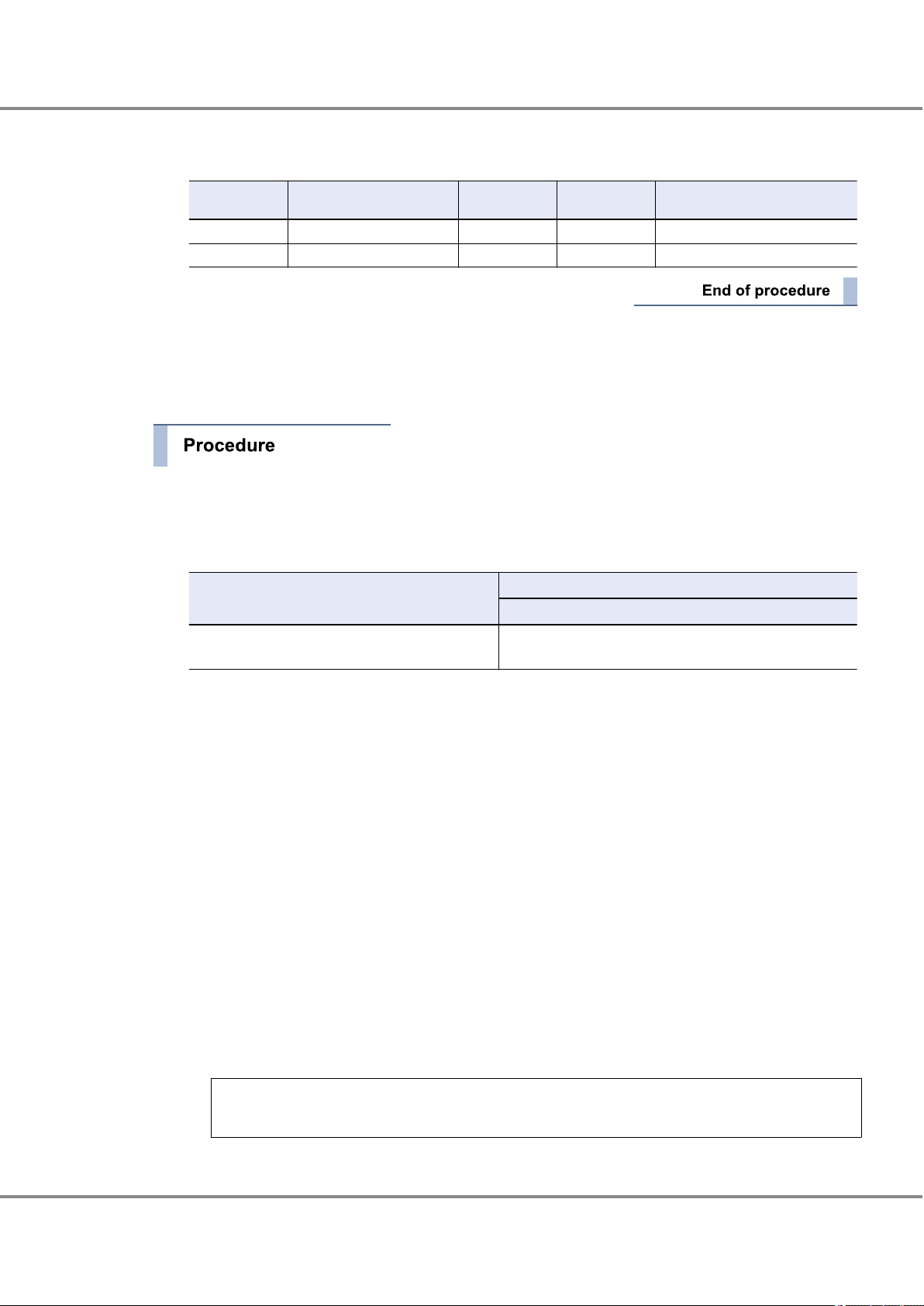
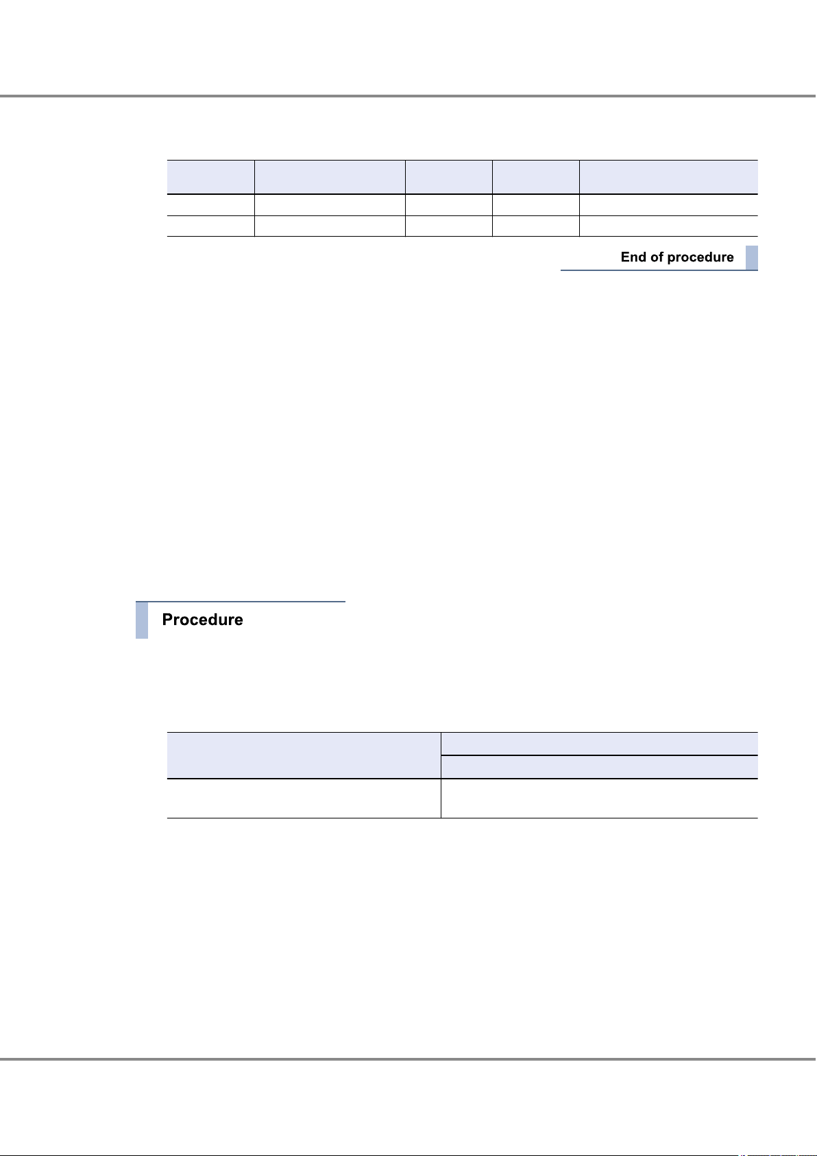
WWN Instance Management Table for the Server
Physical slot name WWN Controller number Instance name Physical path name
1 Check the instance names.
"qlc + instance number" is the format used to represent Fibre Channel card instance names.
The instance number that corresponds to the physical path in which the Fibre Channel card is installed
is stored in the "/etc/path_to_inst" file at the Fibre Channel card driver installation.
Extract necessary parts using the "grep" command.
# grep '"qlc"' /etc/path_to_inst
Example:
# grep '"qlc"' /etc/path_to_inst
"/pci@9,600000/SUNW,qlc@1" 0 "qlc"
/pci@9,600000/SUNW,qlc@2" 1 "qlc"
"
The underlined portion "/pci@9,600000/SUNW,qlc@2" indicates the physical path name, and "1" indicates the instance number.
2 Enter the results in "Instance name" and "Physical path name" columns of the "WWN instance manage-
ment table for the server".
Example:
Physical slot
name
qlc0 /pci@9,600000/SUNW,qlc@1
qlc1 /pci@9,600000/SUNW,qlc@2
WWN
Controller number
Instance name Physical path name
3 Enter the slot number of the Fibre Channel card installed in the server in the "Physical slot name" field
of the "WWN instance management table for the server".
Use the "/usr/platform/'uname-i'/sbin/prtdiag -v" command to check the installed Fibre Channel card
slot number.
Example: Excerpt from "/usr/platform/SUNW,SPARC-Enterprise-T5220/sbin/prtdiag -v" output
FUJITSU Storage ETERNUS DX, ETERNUS AF Configuration Guide -Server Connection- (Fibre Channel) for Oracle Solaris
Copyright 2017 FUJITSU LIMITED
10
P3AM-6312-18ENZ0
Page 11

Chapter 1
1.3 Setting Up the Server
Operations When Using Oracle Fibre Channel Cards
4 Check the WWN of each Fibre Channel card.
(1) Use the following command to check the display order of the Fibre Channel card physical path
(2) Use the following command to check the WWN of the Fibre Channel card that corresponds to the
names.
# prtpicl -v -c scsi-fcp | grep devfs-path
Example:
# prtpicl -v -c scsi-fcp | grep devfs-path
:devfs-path /pci@9,600000/SUNW,qlc@1
:devfs-path /pci@9,600000/SUNW,qlc@2
physical path name. The result is displayed in the same order as shown in Step (1).
# prtpicl -v -c scsi-fcp | grep port-wwn
Example:
# prtpicl -v -c scsi-fcp | grep port-wwn
:port-wwn 21 00 00 e0 8b 12 6d 70
:port-wwn 21 00 00 e0 8b 16 cf fd
5 Add the results in the "WWN instance management table for the server".
Example:
Physical slot
name
PCIE 0 210000e08b126d70 qlc0 /pci@9,600000/SUNW,qlc@1
PCIE 1 210000e08b16cffd qlc1 /pci@9,600000/SUNW,qlc@2
WWN
Controller number
Instance name Physical path name
6 Check the controller number of the target connected to the Fibre Channel card.
Use the following command to check the controller number of the target connected to the Fibre Channel card. The controller number corresponds to the physical path displayed in Step (1).
# cfgadm -v
Example:
# cfgadm -v
Ap_Id Receptacle Occupant Condition Information
When Type Busy Phys_Id
c4 connected unconfigured unknown
unavailable fc-fabric n /devices/pci@9,600000/SUNW,qlc@1/fp@0,0:fc
c5 connected unconfigured unknown
unavailable fc-fabric n /devices/pci@9,600000/SUNW,qlc@2/fp@0,0:fc
11
FUJITSU Storage ETERNUS DX, ETERNUS AF Configuration Guide -Server Connection- (Fibre Channel) for Oracle Solaris
Copyright 2017 FUJITSU LIMITED
P3AM-6312-18ENZ0
Page 12
Chapter 1
1.3 Setting Up the Server
Operations When Using Oracle Fibre Channel Cards
7 Add the results in the "WWN instance management table for the server".
Example:
Physical slot
name
PCIE 0 210000e08b126d70 c4 qlc0 /pci@9,600000/SUNW,qlc@1
PCIE 1 210000e08b16cffd c5 qlc1 /pci@9,600000/SUNW,qlc@2
WWN
Controller number
This completes the "WWN instance management table for the server".
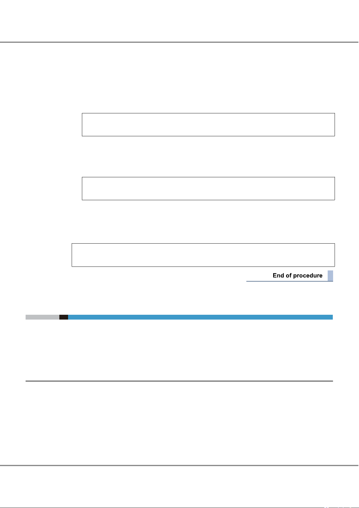
1.3.1.2 Setting the Configuration File (/etc/system)
1 Edit the configuration file.
Edit the configuration file (/etc/system) and specify the command queue depth.
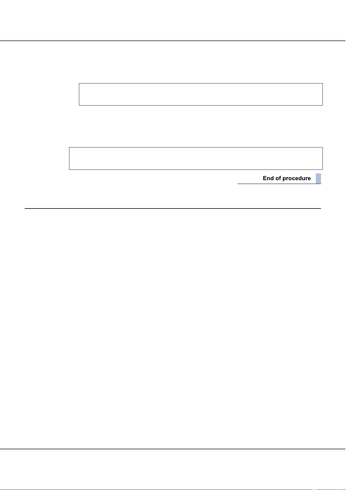
The appropriate command queue depth is determined by the ETERNUS DX/AF model, as follows:
Model
ETERNUS DX/AF Arbitrary (*1)
Instance name Physical path name
Setting value
Command queue depth
(Up to 1024 for each FC port of the ETERNUS DX/AF)
*1: Recommended value = 1024 ¸ (number of Fibre Channel ports that are connected to a single CA
port) ¸ number of LUNs
(Round the result down)
• Use the value of "8" if the actual result is lower.
• To achieve maximum system performance, this value can be changed according to the server
load and the peak operating times.
• The number of simultaneous command executions per CA port for the ETERNUS DX/AF is limited
to 1024. This value is used by multiple servers that share the CA port. A maximum of 1024 commands can be executed per CA port.
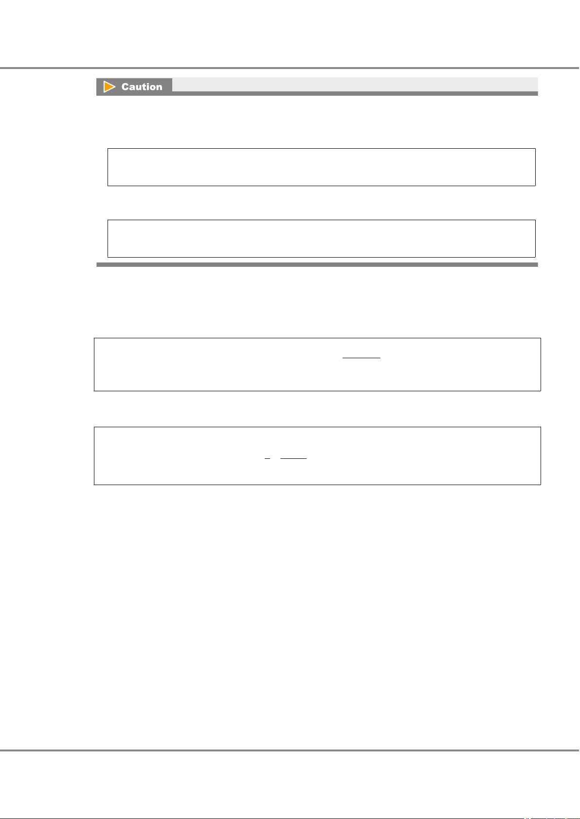
• For the ETERNUS DX/AF
The parameter to be specified for the command queue depth is determined by the CPU which is installed in the server to be connected.
- For SPARC
Specify the command queue depth for the "ssd_max_throttle" parameter.
Add this parameter if it does not exist.
Example:
set ssd:ssd_max_throttle = 20
12
FUJITSU Storage ETERNUS DX, ETERNUS AF Configuration Guide -Server Connection- (Fibre Channel) for Oracle Solaris
Copyright 2017 FUJITSU LIMITED
P3AM-6312-18ENZ0
Page 13
Chapter 1
1.3 Setting Up the Server
Operations When Using Oracle Fibre Channel Cards
2 After editing the configuration file, save it.
3 After the setting is complete, check the configuration file for incorrect settings.
4 Reboot the server.
# /usr/sbin/shutdown -y -g0 -i6
- For x86
Specify the command queue depth for the "sd_max_throttle" parameter.
Add this parameter if it does not exist.
Example:
set sd:sd_max_throttle = 20
1.3.2 Oracle Driver for Emulex OEM Fibre Channel Cards
When connecting using an Emulex OEM Fibre Channel card and Oracle Fibre Channel card driver, the configuration file will need to be edited as follows.
The "command queue depth" setting must be adjusted for both direct connection and switch connection. The
"command queue depth" setting is specified in the configuration file (/etc/system).
● For direct connection
Instance name data of the Fibre Channel card is necessary. Refer to the following sections to set.
"1.3.2.1 Creating a WWN Instance Management Table for the Server" (page 13)
•
"1.3.2.2 Setting the Configuration File (emlxs.conf)" (page 16)
•
"1.3.2.3 Setting the Configuration File (/etc/system)" (page 16)
•
● For switch connection
The Fibre Channel card Instance name, target WWN, and target ID information are necessary. Check each
item and enter them in the table. Edit the configuration file according to those information and make settings. Refer to the following sections to set.
"1.3.2.1 Creating a WWN Instance Management Table for the Server" (page 13)
•
"1.3.2.2 Setting the Configuration File (emlxs.conf)" (page 16)
•
"1.3.2.3 Setting the Configuration File (/etc/system)" (page 16)
•
1.3.2.1 Creating a WWN Instance Management Table for the Server
Create a "WWN instance management table for the server" with information regarding the Fibre Channel card
installed in the server.
For each Fibre Channel card that is installed in the server, check the physical slot names, WWN, instance
names, physical path names, and controller number of the target connected to the Fibre Channel card and
enter them in the "WWN instance management table for the server" (provided in "Appendix A Various Man-
agement Table Templates" (page 82)).
13
FUJITSU Storage ETERNUS DX, ETERNUS AF Configuration Guide -Server Connection- (Fibre Channel) for Oracle Solaris
Copyright 2017 FUJITSU LIMITED
P3AM-6312-18ENZ0
Page 14
# /usr/platform/SUNW,SPARC-Enterprise-T5220/sbin/prtdiag
========================= IO Configuration =================================================
Location Type Slot Path Name Model
MB/PCIE1 PCIE 1 /pci@9,600000/SUNW,emlxs@1,1 SUNW,emlxs-pci10df,fd+LP11002-M4
MB/PCIE0 PCIE 0 /pci@9,600000/SUNW,emlxs@1 SUNW,emlxs-pci10df,fd+LP11002-M4
Physical slot name
WWN
Controller number
Instance name
Physical path name
PCIE 0 emlxs0 /pci@9,600000/SUNW,emlxs@1
PCIE 1 emlxs1 /pci@9,600000/SUNW,emlxs@1,1
Chapter 1
1.3 Setting Up the Server
Operations When Using Oracle Fibre Channel Cards
WWN instance management table for the server
Physical slot name WWN Controller number Instance name Physical path name
1 Check the instance names.
"emlxs + instance number" is the format used to represent Fibre Channel card instance names.
The instance number that corresponds to the physical path in which the Fibre Channel card is installed
is stored in the "/etc/path_to_inst" file at the Fibre Channel card driver installation.
Extract necessary parts using the "grep" command.
# grep "emlxs" /etc/path_to_inst
"/pci@9,600000/SUNW,emlxs@1" 0 "emlxs"
"
/pci@9,600000/SUNW,emlxs@1,1" 1 "emlxs"
The underlined portion "/pci@9,600000/SUNW,emlxs@1,1" indicates the physical path name, and "1"
indicates the instance number.
2 Enter the results in "Instance name" and "Physical path name" columns of the "WWN instance manage-
ment table for the server".
Example:
Physical slot
name
emlxs0 /pci@9,600000/SUNW,emlxs@1
emlxs1 /pci@9,600000/SUNW,emlxs@1,1
WWN
Controller number
Instance name Physical path name
3 Enter the slot number of the Fibre Channel card installed in the server in the "Physical slot name" field
of the "WWN instance management table for the server".
Use the "/usr/platform/`uname -i`/sbin/prtdiag" command to check the installed Fibre Channel card slot
number.
Example: Excerpt from "/usr/platform/SUNW,SPARC-Enterprise-T5220/sbin/prtdiag" output
FUJITSU Storage ETERNUS DX, ETERNUS AF Configuration Guide -Server Connection- (Fibre Channel) for Oracle Solaris
Copyright 2017 FUJITSU LIMITED
14
P3AM-6312-18ENZ0
Page 15
Chapter 1
1.3 Setting Up the Server
Operations When Using Oracle Fibre Channel Cards
4 Check the WWN of each Fibre Channel card.
(1) Execute the following command to check the WWN that corresponds to the Fibre Channel card in-
(2) Use the following command to check the WWN of the Fibre Channel card that corresponds to the
stance name.
# prtpicl -v -c scsi-fcp | grep devfs-path
Example:
# prtpicl -v -c scsi-fcp | grep devfs-path
:devfs-path /pci@9,600000/SUNW,emlxs@1
:devfs-path /pci@9,600000/SUNW,emlxs@1,1
:devfs-path /pci@9,600000/SUNW,emlxs@2
:devfs-path /pci@9,600000/SUNW,emlxs@2,1
physical path name.
# cat /var/adm/messages | grep emlxs0
Example:
# cat /var/adm/messages | grep emlxs0
Sep 12 09:46:50 sfv890b emlxs: [ID 349649 kern.info] [B.125B]emlxs0: NOTICE: 100: Driver attach.
(WWPN:10000000C94CDC42 WWNN:20000000C94CDC42)
# cat /var/adm/messages | grep emlxs1
Sep 12 09:47:15 sfv890b emlxs: [ID 349649 kern.info] [B.125B]emlxs1: NOTICE: 100: Driver attach.
(WWPN:10000000C94CDC43 WWNN:20000000C94CDC43)
5 Add the results in the "WWN instance management table for the server".
Example:
Physical slot
name
10000000C94CDC42 emlxs0 /pci@9,600000/SUNW,emlxs@1
10000000C94CDC43 emlxs1 /pci@9,600000/SUNW,emlxs@1,1
WWN
Controller number
Instance name Physical path name
6 Check the controller number of the target connected to the Fibre Channel card.
Use the following command to check the controller number of the target connected to the Fibre Channel card.
# cfgadm -v
Example:
# cfgadm -v
Ap_Id Receptacle Occupant Condition Information
When Type Busy Phys_Id
c4 connected unconfigured unknown
unavailable fc-fabric n /devices/pci@9,600000/SUNW,emlxs@1/fp@0,0:fc
c5 connected unconfigured unknown
unavailable fc-fabric n /devices/pci@9,600000/SUNW,emlxs@1,1/fp@0,0:fC
15
FUJITSU Storage ETERNUS DX, ETERNUS AF Configuration Guide -Server Connection- (Fibre Channel) for Oracle Solaris
Copyright 2017 FUJITSU LIMITED
P3AM-6312-18ENZ0
Page 16
Chapter 1 Operations When Using Oracle Fibre Channel Cards
1.3 Setting Up the Server
7 Add the results in the "WWN instance management table for the server".
Example:
Physical slot
name
10000000C94CDC42 C4 emlxs0 /pci@9,600000/SUNW,emlxs@1
10000000C94CDC43 C5 emlxs1 /pci@9,600000/SUNW,emlxs@1,1
WWN
Controller number
This completes the "WWN instance management table for the server".
1.3.2.2 Setting the Configuration File (emlxs.conf)
Set the "topology" and "link speed" by editing the configuration file "emlxs.conf".
For setting procedure and parameters, refer to "1.5 Required Driver Parameters" (page 20).
Solaris 11 OS
•
If the "/etc/driver/drv/emlxs.conf” file does not exist, copy the "/kernel/drv/emlxs.conf" file to the "/etc/driver/drv" directory and add the line to the newly copied "emlxs.conf" file.
If the "/etc/driver/drv/emlxs.conf” file exists, do not copy over the file but instead add the line to the existing "emlxs.conf" file.
Solaris 10 OS
•
Edit the "/kernel/drv/emlxs.conf" file.
1.3.2.3 Setting the Configuration File (/etc/system)
Instance name Physical path name
1 Edit the configuration file.
Edit the configuration file (/etc/system) and specify the command queue depth.
The appropriate command queue depth is determined by the ETERNUS DX/AF model, as follows:
Model
ETERNUS DX/AF Arbitrary (*1)
*1: Recommended value = 1024 ¸ (number of Fibre Channel ports that are connected to a single CA
port) ¸ number of LUNs
(Round the result down)
• Use the value of "8" if the actual result is lower.
• To achieve maximum system performance, this value can be changed according to the server
load and the peak operating times.
• The number of simultaneous command executions per CA port for the ETERNUS DX/AF is limited
to 1024. This value is used by multiple servers that share the CA port. A maximum of 1024 commands can be executed per CA port.
Setting value
Command queue depth
(Up to 1024 for each FC port of the ETERNUS DX/AF)
16
FUJITSU Storage ETERNUS DX, ETERNUS AF Configuration Guide -Server Connection- (Fibre Channel) for Oracle Solaris
Copyright 2017 FUJITSU LIMITED
P3AM-6312-18ENZ0
Page 17
Chapter 1
1.4 Setting Up the Server to Recognize the Logical Units
Operations When Using Oracle Fibre Channel Cards
• For the ETERNUS DX/AF
The parameter to be specified for the command queue depth is determined by the CPU which is installed in the server to be connected.
- For SPARC
Specify the command queue depth for the "ssd_max_throttle" parameter.
Add this parameter if it does not exist.
Example:
set ssd:ssd_max_throttle = 20
- For x86
Specify the command queue depth for the "sd_max_throttle" parameter.
Add this parameter if it does not exist.
Example:
set sd:sd_max_throttle = 20
2 After editing the configuration file, save it.
3 After the setting is complete, check the configuration file for incorrect settings.
4 Reboot the server.
# /usr/sbin/shutdown -y -g0 -i6
1.4 Setting Up the Server to Recognize the Logical Units
Make the server recognize the ETERNUS DX/AF logical units using the ssd driver.
If Oracle Fibre Channel cards are used, the logical unit recognition method will depend on the ETERNUS
DX/AF storage systems to server connection topology. There are two possible connection topologies: direct
connection and switch connection.
1.4.1 For Direct Connection
Confirm that the logical units have been correctly recognized by servers.
17
FUJITSU Storage ETERNUS DX, ETERNUS AF Configuration Guide -Server Connection- (Fibre Channel) for Oracle Solaris
Copyright 2017 FUJITSU LIMITED
P3AM-6312-18ENZ0
Page 18

Chapter 1
1.4 Setting Up the Server to Recognize the Logical Units
Operations When Using Oracle Fibre Channel Cards
1 Use the following command to confirm that the storage system has been correctly recognized.
# cfgadm -al
# cfgadm -al
Ap_Id Type Receptacle Occupant Condition
c4 fc-private connected configured unknown
c4::21ff00e000a8ffaf disk connected configured unknown
c5 fc-private connected configured unknown
c5::25ff00e000a8ffaf disk connected configured unknown
The underlined portion indicates that the ETERNUS DX/AF CA (WWN:25 ff00e000a8ffaf) is connected to
the Fibre Channel card port with controller number "c5".
2 Use the following command to confirm that the storage system and all the logical units have been cor-
rectly recognized.
# format
# format
Searching for disks...done
c4t16d0: configured with capacity of 7.98GB
c4t16d1: configured with capacity of 7.98GB
c5t16d0: configured with capacity of 7.98GB
c5t16d1: configured with capacity of 7.98GB
AVAILABLE DISK SELECTIONS:
0. c1t0d0 <SUN36G cyl 24620 alt 2 hd 27 sec 107>
/pci@8,600000/SUNW,qlc@2/fp@0,0/ssd@w21000004cf6851ce,0
c4t16d0 <FUJITSU-ETERNUS_DX8000 cyl 1022 alt 2 hd 64 sec 256>
1.
/pci@9,600000/SUNW,qlc@1/fp@0,0/ssd@w21ff00e000a8ffaf,0
2. c4t16d1 <FUJITSU-ETERNUS_DX8000 cyl 1022 alt 2 hd 64 sec 256>
/pci@9,600000/SUNW,qlc@1/fp@0,0/ssd@w21ff00e000a8ffaf,1
3. c5t16d0 <FUJITSU-ETERNUS_DX8000 cyl 1022 alt 2 hd 64 sec 256>
/pci@9,600000/SUNW,qlc@2/fp@0,0/ssd@w25ff00e000a8ffaf,0
4. c5t16d1 <FUJITSU-ETERNUS_DX8000 cyl 1022 alt 2 hd 64 sec 256>
/pci@9,600000/SUNW,qlc@2/fp@0,0/ssd@w25ff00e000a8ffaf,1
Specify disk (enter its number):
The underlined portion indicates that the ETERNUS DX8100/DX8400/DX8700 target ID=16, lun=0 and 1
are connected to physical path /pci@9,600000/SUNW,qlc@1, and that c4t16d0 and c4t16d1 are assigned to each of these LUNs.
18
FUJITSU Storage ETERNUS DX, ETERNUS AF Configuration Guide -Server Connection- (Fibre Channel) for Oracle Solaris
Copyright 2017 FUJITSU LIMITED
P3AM-6312-18ENZ0
Page 19

Chapter 1
1.4 Setting Up the Server to Recognize the Logical Units
Operations When Using Oracle Fibre Channel Cards
1.4.2 For Switch Connection
Use the following commands to enable the server to access the logical units.
1 Execute the following commands to check the path of the ETERNUS DX/AF to be connected.
# cfgadm -al
Example:
# cfgadm -al
Ap_Id Type Receptacle Occupant Condition
c4 fc-fabric connected unconfigured unknown
c4::21ff00e000a8ffaf disk connected unconfigured unknown
c5 fc-fabric connected unconfigured unknown
c5::25ff00e000a8ffaf disk connected unconfigured unknown
2 Use the following command for each path obtained in Step 1.
Repeat this step for all paths to be used.
# cfgadm -c configure
The underlined portion indicates the path obtained in Step 1.
Example:
# cfgadm -c configure c4::21ff00e000a8ffaf
# cfgadm -c configure c5::25ff00e000a8ffaf
3 Use the following command to confirm that the paths to the ETERNUS DX/AF are now usable.
"Occupant" status changes from "unconfigured" to "configured".
# cfgadm -al
# cfgadm -al
Ap_Id Type Receptacle Occupant Condition
c4 fc-fabric connected configured unknown
c4::21ff00e000a8ffaf disk connected configured unknown
c5 fc-fabric connected configured unknown
c5::25ff00e000a8ffaf disk connected configured unknown
The underlined portion indicates that the ETERNUS DX/AF CA (WWN:25ff00e000a8ffaf) is connected to
the Fibre Channel card port with controller number "c5".
19
FUJITSU Storage ETERNUS DX, ETERNUS AF Configuration Guide -Server Connection- (Fibre Channel) for Oracle Solaris
Copyright 2017 FUJITSU LIMITED
P3AM-6312-18ENZ0
Page 20

Chapter 1
1.5 Required Driver Parameters
Operations When Using Oracle Fibre Channel Cards
4 Use the following command to confirm that the storage system and all the logical units have been cor-
rectly recognized.
# format
# format
Searching for disks...done
c4t16d0: configured with capacity of 7.98GB
c4t16d1: configured with capacity of 7.98GB
c5t16d0: configured with capacity of 7.98GB
c5t16d1: configured with capacity of 7.98GB
AVAILABLE DISK SELECTIONS:
0. c1t0d0 <SUN36G cyl 24620 alt 2 hd 27 sec 107>
/pci@8,600000/SUNW,qlc@2/fp@0,0/ssd@w21000004cf6851ce,0
1. c4t210000E000A8FFAFd0 <FUJITSU-ETERNUS_DX8000 cyl 1022 alt 2 hd 64 sec 256>
/pci@9,600000/SUNW,qlc@1/fp@0,0/ssd@w210000e000a8ffaf,0
2. c4t210000E000A8FFAFd1 <FUJITSU-ETERNUS_DX8000 cyl 1022 alt 2 hd 64 sec 256>
/pci@9,600000/SUNW,qlc@1/fp@0,0/ssd@w210000e000a8ffaf,1
3.
c5t250000E000A8FFAFd0 <FUJITSU-ETERNUS_DX8000 cyl 1022 alt 2 hd 64 sec 256>
/pci@9,600000/SUNW,qlc@2/fp@0,0/ssd@w250000e000a8ffaf,0
4.
c5t250000E000A8FFAFd1 <FUJITSU-ETERNUS_DX8000 cyl 1022 alt 2 hd 64 sec 256>
/pci@9,600000/SUNW,qlc@2/fp@0,0/ssd@w250000e000a8ffaf,1
Specify disk (enter its number):
The underlined portion indicates that the target ID=250000E000A8FFAF, lun=0 and 1 are connected
and that c5t250000E000A8FFAFd0 and c5t250000E000A8FFAFd1 are assigned to each of these LUNs.
1.5 Required Driver Parameters
1.5.1 Emulex OEM Fibre Channel Card Setup
If an Oracle driver for an Emulex OEM Fibre Channel card is used, the parameters of the "emlxs.conf" configuration file needs to be edited using the "vi" command. Edit the file in accordance with the
"1.5.2 emlxs.conf Parameter List" (page 22).
Solaris 11 OS
•
If the "/etc/driver/drv/emlxs.conf” file does not exist, copy the "/kernel/drv/emlxs.conf" file to the "/etc/driver/drv" directory and edit the newly copied "emlxs.conf" file.
If the "/etc/driver/drv/emlxs.conf” file exists, do not copy over the file but instead edit the existing
"emlxs.conf" file.
Solaris 10 OS
•
Edit the "/kernel/drv/emlxs.conf" file.
20
FUJITSU Storage ETERNUS DX, ETERNUS AF Configuration Guide -Server Connection- (Fibre Channel) for Oracle Solaris
Copyright 2017 FUJITSU LIMITED
P3AM-6312-18ENZ0
Page 21
Chapter 1
1.5 Required Driver Parameters
Operations When Using Oracle Fibre Channel Cards
Original configuration file must be backed up before editing.
If Solaris 11 OS is used and the "/etc/driver/drv/emlxs.conf” file exists
•
Example:
cp /etc/driver/drv/emlxs.conf ./emlxs.conf.backup
Solaris 10 OS
•
Example:
cp /kernel/drv/emlxs.conf ./emlxs.conf.backup
Instance names are specified for some item names, but not for others.
Confirm the X part of "emlxsX" with the /var/adm/messages file or the /etc/path_to_inst file.
The following examples show the two confirmation methods:
Example 1: Check with the "/var/adm/messages" file.
Aug155:59:27 sfv890a genunix: [ID 936769 kern.info] "emlxs0" is /pci@9,600000/fibre-channel@1
Aug 15 15:59:27 sfv890a emlxs: [ID 349649 kern.info] [B.03F0]emlxs0: NOTICE: 720: Link up
(2Gb,fabric *)
The underlined portion indicates the instance name and the instance number.
Example 2: Check with the "/etc/path_to_inst".
"/pci@9,600000" 3 "pcisch"
"/pci@9,600000/fibre-channel@1" 0 "emlxs"
"/pci@9,600000/fibre-channel@1/fp@0,0" 0 "fp"
The underlined portion indicates the instance number and the instance name.
21
FUJITSU Storage ETERNUS DX, ETERNUS AF Configuration Guide -Server Connection- (Fibre Channel) for Oracle Solaris
Copyright 2017 FUJITSU LIMITED
P3AM-6312-18ENZ0
Page 22

Chapter 1 Operations When Using Oracle Fibre Channel Cards
1.5 Required Driver Parameters
1.5.2 emlxs.conf Parameter List
Parameter
num-iocbs 1024 1024 — —
ub-bufs 1000 1000 — —
network-on 1 1 — —
emlxsX-topology 4 2 (*1) Yes An instance name is
emlxsX-link-speed 2, 4, or 8 0, 2, 4, or 8 (*1) Yes An instance name is
ack 0 0 — —
cr-delay 0 0 — —
cr-count 1 1 — —
assign-alpa 0x00 0x00 — —
adisc-support 1 1 — —
pm-support 0 0 — —
num-nodes 0 0 — —
Setting value
(for direct connection)
Setting value
(for switch connec-
tion)
emlxsX
instance name
Remarks
specified for each instance.
specified for each instance (*2).
*1: Specify "2" for "emlxsX-topology" and "0" for "emlxsX-link-speed" when using direct connections to
16Gbit/s Fibre Channel cards with a transfer rate of 16Gbit/s.
*2: "emlxsX-link-speed" setting value
Fibre Channel
card transfer
rate
16Gbit/s 0 8 4 — — —
8Gbit/s 8 8 4 2 8 4
4Gbit/s 4 4 4 2 4 4
2Gbit/s — 2 2 2 2 2
Switch connection
Fibre Channel switch transfer rate
16Gbit/s 8Gbit/s 4Gbit/s 2Gbit/s 8Gbit/s 4Gbit/s
Direct connection
CA transfer rate
22
FUJITSU Storage ETERNUS DX, ETERNUS AF Configuration Guide -Server Connection- (Fibre Channel) for Oracle Solaris
Copyright 2017 FUJITSU LIMITED
P3AM-6312-18ENZ0
Page 23

# COPYRIGHT E004-2008 Emulex. All rights reserved.
# Solaris LightPulse emlxs driver: global initialized data.
#
# console-notices: Sets the verbose level for driver notices to the console.
# console-warnings: Sets the verbose level for driver warnings to the console.
# console-errors: Sets the verbose level for driver errors to the console.
#
# log-notices: Sets the verbose level for driver notices to the system log file*.
# log-warnings: Sets the verbose level for driver warnings to the system log file*.
# log-errors: Sets the verbose level for driver errors to the system log file*.
#
# *NOTE: The system log file is normally found at /var/adm/messages.
#
# Each parameter is a bit mask that enables/disables specific types of messages.
# If the bit is set, then the messages of that type are enabled.
#
# The available message types are listed below:
#
# LOG_MISC 0x00000001 /* Misc events */
# LOG_DRIVER 0x00000002 /* Driver attach and detach events */
# LOG_INIT 0x00000004 /* HBA initialization events */
# LOG_MEM 0x00000008 /* Memory management events */
# LOG_SLI 0x00000010 /* Service Level Interface (SLI) events */
# LOG_MBOX 0x00000020 /* Mailbox events */
# LOG_NODE 0x00000040 /* Node events */
# LOG_LINK 0x00000080 /* Link events */
# LOG_ELS 0x00000100 /* ELS events */
# LOG_PKT 0x00000200 /* General I/O packet events */
# LOG_FCP 0x00000400 /* FCP traffic events */
# LOG_TGTM 0x00000800 /* FCP target mode events */
# LOG_IP 0x00001000 /* IP traffic events */
# LOG_SFS 0x00002000 /* SFS events */
# LOG_IOCTL 0x00004000 /* IOCtl events */
# LOG_FIRMWARE 0x00008000 /* Firmware download events */
# LOG_CT 0x00010000 /* CT events */
# LOG_FCSP 0x00020000 /* FCSP events */
# LOG_RESERVED 0xfffc0000 /* Reserved for future use */
#
# Range: Min:0 Max:0xffffffff
#
# console-notices = 0; (Default)
# console-warnings = 0; (Default)
# console-errors = 0; (Default)
#
# log-notices = 0xffffffff; (Default)
# log-warnings = 0xffffffff; (Default)
# log-errors = 0xffffffff; (Default)
#
console-notices=0;
console-warnings=0;
console-errors=0;
log-notices=0xffffffff;
log-warnings=0xffffffff;
log-errors=0xffffffff;
# num-iocbs: Sets the number of iocb buffers to allocate.
#
# Range: Min:128 Max:10240 Default:1024
#
num-iocbs=1024;
# ub-bufs: Sets the number of unsolicited buffers to be allocated.
#
# Range: Min:40 Max:16320 Default:1000
#
ub-bufs=1000;
#
# +++ Variables relating to IP networking support. +++
#
# network-on: Enable/Disable IP networking support in the driver.
#
# 0 = Disables IP networking support in the driver.
# 1 = Enables IP networking support in the driver.
#
# Range: Min:0 Max:1 Default:1
#
network-on=1;
#
# +++ Fibre Channel specific parameters +++
#
# topology: link topology for initializing the Fibre Channel connection.
#
Chapter 1 Operations When Using Oracle Fibre Channel Cards
1.5 Required Driver Parameters
1.5.3 emlxs.conf Parameter Example
A switch connection example is shown below.
FUJITSU Storage ETERNUS DX, ETERNUS AF Configuration Guide -Server Connection- (Fibre Channel) for Oracle Solaris
Copyright 2017 FUJITSU LIMITED
23
P3AM-6312-18ENZ0
Page 24

# 0 = attempt loop mode, if it fails attempt point-to-point mode
# 2 = attempt point-to-point mode only
# 4 = attempt loop mode only
# 6 = attempt point-to-point mode, if it fails attempt loop mode
#
# Set point-to-point mode if you want to run as an N_Port.
# Set loop mode if you want to run as an NL_Port.
#
# Range: Min:0 Max:6 Default:0
#
#topology=0;
emlxs0-topology=2;
emlxs1-topology=2;
# link-speed: Sets the link speed setting for initializing the Fibre Channel
# connection.
#
# 0 = auto select
# 1 = 1 Gigabaud
# 2 = 2 Gigabaud
# 4 = 4 Gigabaud
# 8 = 8 Gigabaud
#
# Range: Min:0 Max:8 Default:0
#
link-speed=0;
emlxs0-link-speed=8;
emlxs1-link-speed=8;
# ack0: Determines if ACK0 is used instead of ACK1 for class 2
# acknowledgement.
#
# 0 = The driver will use ACK1 for class 2 acknowledgement.
# 1 = The driver will use ACK0 for class 2 acknowledgement.
#
# Range: Min:0 Max:1 Default:0
#
ack0=0;
# cr-delay: Sets the coalesce response delay in the adapter.
#
# This value specifies a count of milliseconds after which an interrupt
# response is generated if cr-count has not been satisfied. This value is
# set to 0 to disable the Coalesce Response feature as default.
#
# Range: Min:0 Max:63 Default:0
#
cr-delay=0;
# cr-count: Sets the coalesce response count in the adapter.
#
# This value specifies a count of I/O completions after which an interrupt
# response is generated. This feature is disabled if cr-delay is set to 0.
#
# Range: Min:1 Max:255 Default:1
#
cr-count=1;
# assign-alpa: Sets a preferred ALPA for the adapter.
#
# This is only valid if topology is loop. A zero setting means no preference.
# If multiple adapter instances on the same host are on the same loop,
# you will want to set this value differently for each adapter.
#
# For example: emlxs0-assign-alpa=0x01; assigns ALPA 0x01 to adapter 0
# emlxs1-assign-alpa=0x02; assigns ALPA 0x02 to adapter 1
# emlxs2-assign-alpa=0x04; assigns ALPA 0x04 to adapter 2
#
# Range: Min:0x00 Max:0xef Default:0x00 (valid ALPA's only)
#
assign-alpa=0x00;
# adisc-support: Sets the ADISC login support level.
#
# This sets the level of driver support for the Fibre Channel ADISC
# login I/O recovery method.
#
# 0 = No support. Flush active I/O's for all FCP target devices at link down.
# 1 = Partial support. Flush I/O's for non-FCP2 target devices at link down.
# 2 = Full support. Hold active I/O's for all devices at link down.
#
# Range: Min:0 Max:2 Default:1
#
adisc-support=1;
# pm-support: Enable/Disable power management support in the driver.
#
For direct connections, emlxs0-topology=4;
For both direct connections and switch connections, add these settings.
Chapter 1 Operations When Using Oracle Fibre Channel Cards
1.5 Required Driver Parameters
24
FUJITSU Storage ETERNUS DX, ETERNUS AF Configuration Guide -Server Connection- (Fibre Channel) for Oracle Solaris
Copyright 2017 FUJITSU LIMITED
P3AM-6312-18ENZ0
Page 25

# 0 = Disables power management support in the driver.
# 1 = Enables power management support in the driver.
#
# Range: Min:0 Max:1 Default:0
#
pm-support=0;
# num-nodes: Number of fibre channel nodes (NPorts) the driver will support.
#
# 0 = Indicates auto detect limit of adapter.
#
# Range: Min:0 Max:4096 Default:0
#
num-nodes=0;
# pci-max-read: Sets the PCI-X max memory read byte count on the adapter.
#
# This value controls the adapter’s max PCI-X memory read count.
# On Sunfire x4100/4200 systems this parameter must be changed to
# 1024 bytes. Currently, this parameter should only be modified on
# Sunfire x4100/4200 systems due to the unique nature of the PCI-X bus
# on these systems, otherwise it should be left as default.
#
# Options: 512, 1024, 2048, 4096
#
# Range: Min:512 Max:4096 Default:2048
#
# *Uncomment this parameter for Sunfire x4100/4200 systems only
#pci-max-read=1024;
# linkup-delay: Sets the linkup delay period (seconds) after initialization.
#
# This value controls how long the driver waits for the Fibre Channel
# link to come up after an adapter reset before continuing normal operation.
#
# Range: Min:0 Max:60 Default:10
#
linkup-delay=10;
# enable-npiv: Enables NPIV support in the driver.
#
# Requires SLI3 mode support in the adapter firmware.
#
# Range: Min:0 Max:1 Default:0
#
enable-npiv=0;
# vport-restrict-login: Restricts login to virtual ports to conserve resources.
#
# Requires SLI3 mode support in the adapter firmware.
# Requires enable-npiv parameter to be set to 1.
#
# Range: Min:0 Max:1 Default:1
#
vport-restrict-login=1;
# vport: Virtual port registration table.
# The enable-npiv must be set to 1.
#
# The vport table may have any number of comma delimited entries.
# Each entry must be of the form:
#
# "PHYS_WWPN:VPORT_WWNN:VPORT_WWPN:VPORT_ID"
#
# PHYS_WWPN = World Wide Port Name of adapter’s physical port
# VPORT_WWNN = Desired World Wide Node Name of virtual port
# VPORT_WWPN = Desired World Wide Port Name of virtual port
# VPORT_ID = Desired virtual port id (1 to max vports)
# The port ids must start at 1 and increment by 1
# with no gaps in the count.
#
# Example:
#
# vport="10000000c9123456:28010000c9123456:20010000c9123456:1",
# "10000000c9123456:28020000c9123456:20020000c9123456:2",
# "10000000c9123457:28010000c9123457:20010000c9123457:1",
# "10000000c9123457:28020000c9123457:20020000c9123457:2",
# "10000000c9123457:28030000c9123457:20030000c9123457:3";
#
# enable-auth: Enables DHCHAP support in the driver.
#
# Range: Min:0 Max:1 Default:0
#
enable-auth=0;
# max-xfer-size: Sets the maximum SCSI transfer size in bytes per IO
# This parameter is only used by the driver on i386 platforms.
# The driver does not limit transfer size on SPARC platforms.
Chapter 1 Operations When Using Oracle Fibre Channel Cards
1.5 Required Driver Parameters
FUJITSU Storage ETERNUS DX, ETERNUS AF Configuration Guide -Server Connection- (Fibre Channel) for Oracle Solaris
Copyright 2017 FUJITSU LIMITED
25
P3AM-6312-18ENZ0
Page 26

#
# This parameter determines the scatter gather list buffer size.
# A pool of buffers is reallocated by the driver during boot.
# A larger transfer size requires a larger memory allocation.
#
# Memory_model max-xfer-size
# ---------------------------------------# Small 131072 - 339968
# Medium 339969 - 688128
# Large 688129 - 1388544
#
# Range: Min:131072 Max:1388544 Default:339968
#
max-xfer-size=339968;
Chapter 1 Operations When Using Oracle Fibre Channel Cards
1.5 Required Driver Parameters
FUJITSU Storage ETERNUS DX, ETERNUS AF Configuration Guide -Server Connection- (Fibre Channel) for Oracle Solaris
Copyright 2017 FUJITSU LIMITED
26
P3AM-6312-18ENZ0
Page 27

Chapter 2
Setup Procedure for Emulex Fibre Channel Cards
This chapter describes the procedures for "Installing the Driver and Setting Up the Server" and "Recognizing
the Logical Units" required to establish a connection between a server with Emulex Fibre Channel cards and
an ETERNUS DX/AF.
2.1 Workflow
Workflow
Installing the Fibre Channel Card Driver
Install the driver. Download the proper driver from the Emulex web-site as required.
"2.2 Installing the Fibre Channel Card Driver" (page 28)
•
Driver (downloaded from web-site)
•
Used for driver installation
•
Manual (downloaded from web-site)
-
Creating Various Management Tables
Enter the necessary information in the "WWN Instance Management Table for the Server", "WWN Instance Management Table for Storage System", and "Target Binding Table".
"2.3 Setting Up the Server" (page 31)
•
"Appendix A Various Management Table Templates" (page 82)
•
Editing the Configuration File
Set the driver parameters by editing the configuration file.
"2.3 Setting Up the Server" (page 31)
•
"2.5 Required Driver Parameters" (page 40)
•
27
FUJITSU Storage ETERNUS DX, ETERNUS AF Configuration Guide -Server Connection- (Fibre Channel) for Oracle Solaris
Copyright 2017 FUJITSU LIMITED
P3AM-6312-18ENZ0
Page 28
Chapter 2
2.2 Installing the Fibre Channel Card Driver
Setup Procedure for Emulex Fibre Channel Cards
Setting Up the Server to Recognize the Logical Units (LUNs)
Make the server recognize the ETERNUS DX/AF logical units using the sd driver.
"2.4 Setting Up the Server to Recognize the Logical Units" (page 36)
•
After completing all the required procedures in this manual, proceed to "Setting the Multipaths" in
"Configuration Guide -Server Connection- (Fibre Channel) for Oracle Solaris".
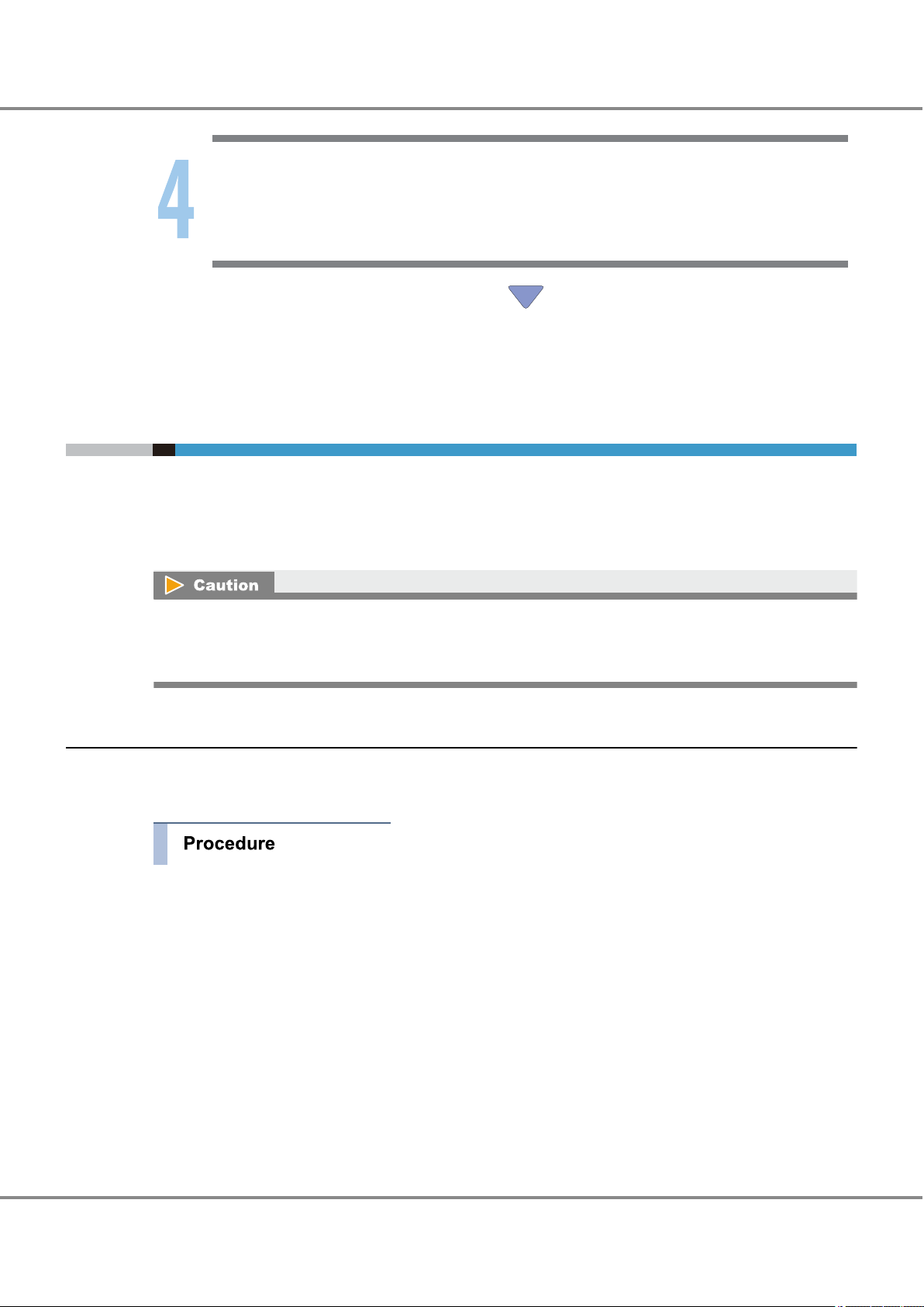
2.2 Installing the Fibre Channel Card Driver
Install the Fibre Channel card driver.
Which of the following Fibre Channel card driver installation and set up procedures is used depends on
whether a newer (Solaris 10 OS Update 1 or later) or older (Solaris 10 OS, Solaris 9 OS, or Solaris 8 OS) version of the OS being used. The following explains for each version of the OS being used.
If using Emulex Fibre Channel cards, note that while the following warning message may appear during
server startup, it has no effect on the server or ETERNUS DX/AF.
Warning lpfcX:129:FCP Read Check Error. ("X" is instance number)
2.2.1 Solaris 10 OS Update1 or Later
Solaris 10 OS Update 1 and later include the SFS driver with the OS. For Emulex Fibre Channel cards, switch
the driver so that the Emulex driver (lpfc driver) is used instead of the SFS driver.
1 Apply the patch.
Sun released patch 120222-6 or later installed
2 Install the Emulex FCA Utility.
Download the Emulex FCA Utility from the following web site.
For details of installation, refer to the FCA Utility Manual in the following Emulex web-site:
http://www.emulex.com
3 Check that Emulex lpfc driver is not installed.
If installed, uninstall it using "pkgrm" command.
28
FUJITSU Storage ETERNUS DX, ETERNUS AF Configuration Guide -Server Connection- (Fibre Channel) for Oracle Solaris
Copyright 2017 FUJITSU LIMITED
P3AM-6312-18ENZ0
Page 29

Chapter 2
2.2 Installing the Fibre Channel Card Driver
Setup Procedure for Emulex Fibre Channel Cards
By the following method, Emulex lpfc driver can be checked and uninstalled.
• Check the package
#pkginfo -l lpfc
• Uninstallation method
#pkgrm lpfc
The following package is currently installed:
lpfc Emulex LightPulse FC SCSI/IP Host Bus Adapter driver
(sparc) Release 6.02h
Do you want to remove this package? [y,n,?,q] y
4 Unbind the Emulex driver using the Emulex FCA Utility.
For details, refer to "Emulex FCA Utility Manual" and "Solaris 10 OS Update 1 behavior change must read
before downloading driver Manual".
Perform the following procedure to unbind the Emulex driver.
(1) Move to the Emulex FCA utility directory.
#cd /opt/EMLXemlxu/bin
29
FUJITSU Storage ETERNUS DX, ETERNUS AF Configuration Guide -Server Connection- (Fibre Channel) for Oracle Solaris
Copyright 2017 FUJITSU LIMITED
P3AM-6312-18ENZ0
Page 30
Chapter 2
2.2 Installing the Fibre Channel Card Driver
Setup Procedure for Emulex Fibre Channel Cards
(2) Launch the Emulex FCA utility using the following command.
# ./emlxdrv
# ./emlxdrv
EMLXDRV Driver Management Utility, Version 1.00j
COPYRIGHT E004-2005 Emulex. All rights reserved.
Driver Alias Present Boot Sun Models
------------------------------------------------------------------------- emlxs lpfs no no no LP8000S and LP9002S (SBUS) (SBUS)
emlxs f800 no no no LP8000 and LP8000DC
emlxs f900 no no no LP9002, LP9002C, LP9002DC, and LP9402DC
emlxs f980 no no no LP9802 and LP9802DC
emlxs fa00 yes no no LP10000, LP10000DC and LP10000ExDC
emlxs fd00 no no no LP11000 and LP11002
emlxs fe00 no no no LPe11000 and LPe11002
- f0a5 no no no 2G Blade Adapter (emlxs only)
emlxs fc00 no no yes LP10000-S and LP10000DC-S
- fc20 no no yes LPe11000-S and LPe11002-S
Available commands:
------------------------------------------------------------------------- set_emlxs <Alias>-Sets emlxs driver to bind to the specified device(s)
set_emlxs_sun -Sets emlxs driver to bind to all Sun devices
set_emlxs_all -Sets emlxs driver to bind to all devices
set_lpfc <Alias> -Sets lpfc driver to bind to the specified device(s)
set_lpfc_nonsun -Sets lpfc driver to bind to all non-Sun devices
clear_dev <Alias>-Clears driver binding to the specified device(s)
clear_lpfc -Clears all lpfc driver bindings
clear_emlxs -Clears all emlxs driver bindings
clear_sun -Clears driver bindings to all Sun devices
clear_nonsun -Clears driver bindings to all non-Sun devices
clear_all -Clears driver bindings to all devices
q -Exits this program.
emlxdrv>
(3) Unbind the Emulex driver using the following command.
emlxdrv>clear_all
Quit the utility using the following command.
emlxdrv>q
(4) Install the driver.
Download and install the lpfc driver from the Emulex web-site.
2.2.2 Solaris 10 OS, Solaris 9 OS, or Solaris 8 OS
Download and install the driver from the Emulex web-site.
30
FUJITSU Storage ETERNUS DX, ETERNUS AF Configuration Guide -Server Connection- (Fibre Channel) for Oracle Solaris
Copyright 2017 FUJITSU LIMITED
P3AM-6312-18ENZ0
Page 31

Chapter 2 Setup Procedure for Emulex Fibre Channel Cards
2.3 Setting Up the Server
2.3 Setting Up the Server
The server setup will vary according to how the ETERNUS DX/AF storage systems and server are to be connected.
Edit the server's configuration file to match the chosen topology. Configuration files may also differ depending on which Fibre Channel cards are to be used.
There are two possible connection topologies: direct connection and switch connection.
● For direct connection
Instance name data of the Fibre Channel card is necessary. Refer to the following sections to set.
"2.3.1 Creating a WWN Instance Management Table for the Server" (page 31)
•
"2.3.2 Creating a WWN Instance Management Table for Storage System" (page 33)
•
"2.3.4 Setting the Configuration File" (page 35)
•
"2.3.5 Re-checking the Settings" (page 35)
•
● For switch connection
The Fibre Channel card Instance name, target WWN, and target ID information are necessary. Check each
item and enter them in the table. Edit the configuration file according to those information and make settings. Refer to the following sections to set.
"2.3.1 Creating a WWN Instance Management Table for the Server" (page 31)
•
"2.3.2 Creating a WWN Instance Management Table for Storage System" (page 33)
•
"2.3.3 Creating a Target Binding Table" (page 34)
•
"2.3.4 Setting the Configuration File" (page 35)
•
"2.3.5 Re-checking the Settings" (page 35)
•
2.3.1 Creating a WWN Instance Management Table for the Server
Create a "WWN instance management table for the server" with information regarding the Fibre Channel
card.
Determine the following information for each Fibre Channel card installed in the server and enter it into a
copy of the "WWN instance management table for the server" (provided in "Appendix A Various Management
Table Templates" (page 82)).
Physical slot name
•
WWN
•
Instance name
•
Physical path name
•
WWN instance management table for the server
Physical slot name
WWN Instance name Physical path name
31
FUJITSU Storage ETERNUS DX, ETERNUS AF Configuration Guide -Server Connection- (Fibre Channel) for Oracle Solaris
Copyright 2017 FUJITSU LIMITED
P3AM-6312-18ENZ0
Page 32

Nov 17 10:27:40 t5220.i14y-ux.com lpfc: [ID 129691 kern.notice] NOTICE: lpfc0: Firmware Rev 1.10A5 (U2D1.10A5)
Nov 17 10:27:40 t5220.i14y-ux.com lpfc: [ID 651404 kern.notice] NOTICE: lpfc0: Fcode Rev 3.10a3
Nov 17 10:27:40 t5220.i14y-ux.com lpfc: [ID 507530 kern.notice] NOTICE: lpfc0: WWPN:10:00:00:00:c9:36:60:46
WWNN:20:00:00:00:c9:36:60:46 MSIX:2
Nov 17 10:27:40 t5220.i14y-ux.com lpfc: [ID 396126 kern.info] NOTICE: Device Path for interface lpfc0:
Nov 17 10:27:40 t5220.i14y-ux.com pxb_plx: [ID 370704 kern.info] PCI-device: lpfc@0,1, lpfc0
Nov 17 10:27:40 t5220.i14y-ux.com genunix: [ID 936769 kern.info] lpfc0 is /pci@0/pci@0/pci @8/pci@0/pci@9/lpfc@0,1
Nov 17 10:26:24 t5220.i14y-ux.com lpfc: [ID 129691 kern.notice] NOTICE: lpfc1: Firmware Rev 1.10A5 (U2D1.10A5)
Nov 17 10:26:24 t5220.i14y-ux.com lpfc: [ID 651404 kern.notice] NOTICE: lpfc1: Fcode Rev 3.10a3
Nov 17 10:26:24 t5220.i14y-ux.com lpfc: [ID 507530 kern.notice] NOTICE: lpfc1: WWPN:10:00:00:00:c9:36:5d:9e
WWNN:20:00:00:00:c9:36:5d:9e MSIX:2
Nov 17 10:26:24 t5220.i14y-ux.com lpfc: [ID 396126 kern.info] NOTICE: Device Path for interface lpfc1:
Nov 17 10:26:24 t5220.i14y-ux.com pxb_plx: [ID 370704 kern.info] PCI-device: lpfc@0,1, lpfc1
Nov 17 10:26:24 t5220.i14y-ux.com genunix: [ID 936769 kern.info] lpfc1 is /pci@0/pci@0/pci@8/pci@0/pci@1/lpfc@0,1
Instance name
WWN
Chapter 2
2.3 Setting Up the Server
Setup Procedure for Emulex Fibre Channel Cards
1 Check the instance names.
"lpfc + instance number" is the format used to represent Fibre Channel card instance names.
The instance number that corresponds to the physical path in which the Fibre Channel card is installed
is stored in the "/etc/path_to_inst" file at the Fibre Channel card driver installation.
Extract necessary parts using the "grep" command.
# grep "lpfc" /etc/path_to_inst
Example:
"/pci@9,600000/lpfc@1" 0 "lpfc"
"
The underlined portion "/pci@9,600000/lpfc@2" indicates the physical path name, and "1" indicates the
instance number.
/pci@9,600000/lpfc@2" 1 "lpfc"
"lpfc0" is the instance name of the "/pci@9,600000/lpfc@1" path Fibre Channel card. "lpfc1" is the
instance name of the "/pci@9,600000/lpfc@2" path Fibre Channel card.
2 Enter the results in "Instance name" and "Physical path name" columns of the "WWN instance manage-
ment table for the server".
Example:
Physical slot name WWN Instance name Physical path name
lpfc0 /pci@9,600000/lpfc@1
lpfc1 /pci@9,600000/lpfc@2
3 Check the WWN of each Fibre Channel card.
Open the "/var/adm/messages" file to identify the WWNs.
(The "WWPN" value in the 3rd line is a WWN, with an instance name of "lpfc0".)
(The "WWPN" value in the 11th line is a WWN, with an instance name of "lpfc1".)
FUJITSU Storage ETERNUS DX, ETERNUS AF Configuration Guide -Server Connection- (Fibre Channel) for Oracle Solaris
Copyright 2017 FUJITSU LIMITED
32
P3AM-6312-18ENZ0
Page 33

Chapter 2 Setup Procedure for Emulex Fibre Channel Cards
2.3 Setting Up the Server
4 Add the results in the "WWN instance management table for the server".
Example:
Physical slot name WWN Instance name Physical path name
10000000c9366046 lpfc0 /pci@9,600000/lpfc@1
10000000c9365d9e lpfc1 /pci@9,600000/lpfc@2
2.3.2 Creating a WWN Instance Management Table for Storage System
Create a "WWN instance management table for storage system" that summarizes information relating to CA
in the ETERNUS DX/AF storage systems.
WWN Instance Management Table for Storage System
Channel Adapter WWN T_ID
Check the following items and enter them in the WWN instance management table for storage system.
Channel Adapter
•
CA name in the ETERNUS DX/AF storage systems
WWN
•
The WWN for each CA in the ETERNUS DX/AF (check using ETERNUSmgr)
T_ID
•
The SCSI target ID (decimal value) that is to be defined for each CA
For switch connections, the SCSI target ID is irrelevant to the physical protocol, however it must be defined
as a Solaris OS SCSI driver setting. Values matched to the server environment and connection state of the
devices must be set beforehand.
It is recommended to set the same target ID to CAs that configures a multipath.
(Example) When there are two ports on the ETERNUS DX/AF storage systems:
Channel Adapter WWN Alias name T_ID
CM0CA0Port0 202000e000cb0001 DX400_CM0CA0P0 16
CM1CA0Port0 203000e000cb0001 DX400_CM1CA0P0 16
33
FUJITSU Storage ETERNUS DX, ETERNUS AF Configuration Guide -Server Connection- (Fibre Channel) for Oracle Solaris
Copyright 2017 FUJITSU LIMITED
P3AM-6312-18ENZ0
Page 34

Server#0
Slot0
Slot1
CA0 Port0
CM0
CA0 Port1
ETERNUS DX/AF
Fibre Channel Switch A Fibre Channel Switch B
CM1
CA0 Port1 CA0 Port0
Chapter 2
2.3 Setting Up the Server
Setup Procedure for Emulex Fibre Channel Cards
2.3.3 Creating a Target Binding Table
This procedure is not necessary for direct connections.
Target binding logically binds the Fibre Channel card installed in the server, and the CA on the ETERNUS
DX/AF storage systems to be connected to the server.
Target binding binds the instance name of the Fibre Channel card, channel adapter name, WWN, and target
ID.
Enter the required information for target binding in the "target binding table". Create "Target binding tables"
for each server to be connected.
Enter the following information in the target binding table.
Name of target server
•
Channel Adapter names and their SCSI target IDs
•
The "channel adapter names" and "target IDs" entered in the "WWN instance management table for storage system"
RAID-WWN
•
The WWN entered in the "WWN instance management table for storage system"
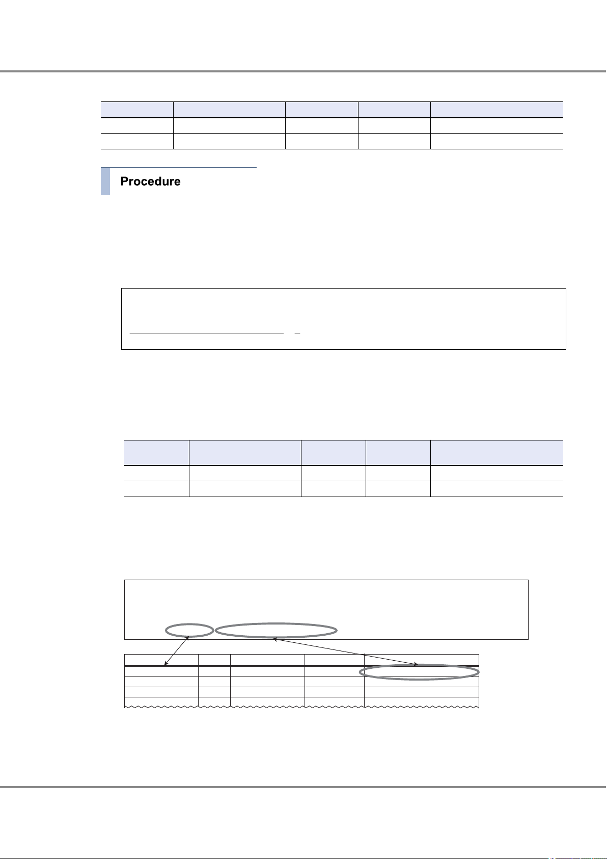
1 Enter the target information to be set for the server.
Reflect the information from the "WWN instance management table for storage system" in the "target
binding table".
Target Binding Table
Server name: Server1
Channel Adapter name SCSI T-ID RAID-WWN Instance name
CM0CA0 16 202000c000cb0001
CM1CA0 16 203000c000cb0001
2 Confirm the connection path(s) in the system.
Example:
Physical slots on Server#0 and CAs on the ETERNUS DX/AF storage systems are connected in the following paths.
• Server#0 SLOT0 - CM0CA0
• Server#0 SLOT1 - CM1CA0
FUJITSU Storage ETERNUS DX, ETERNUS AF Configuration Guide -Server Connection- (Fibre Channel) for Oracle Solaris
34
Copyright 2017 FUJITSU LIMITED
P3AM-6312-18ENZ0
Page 35

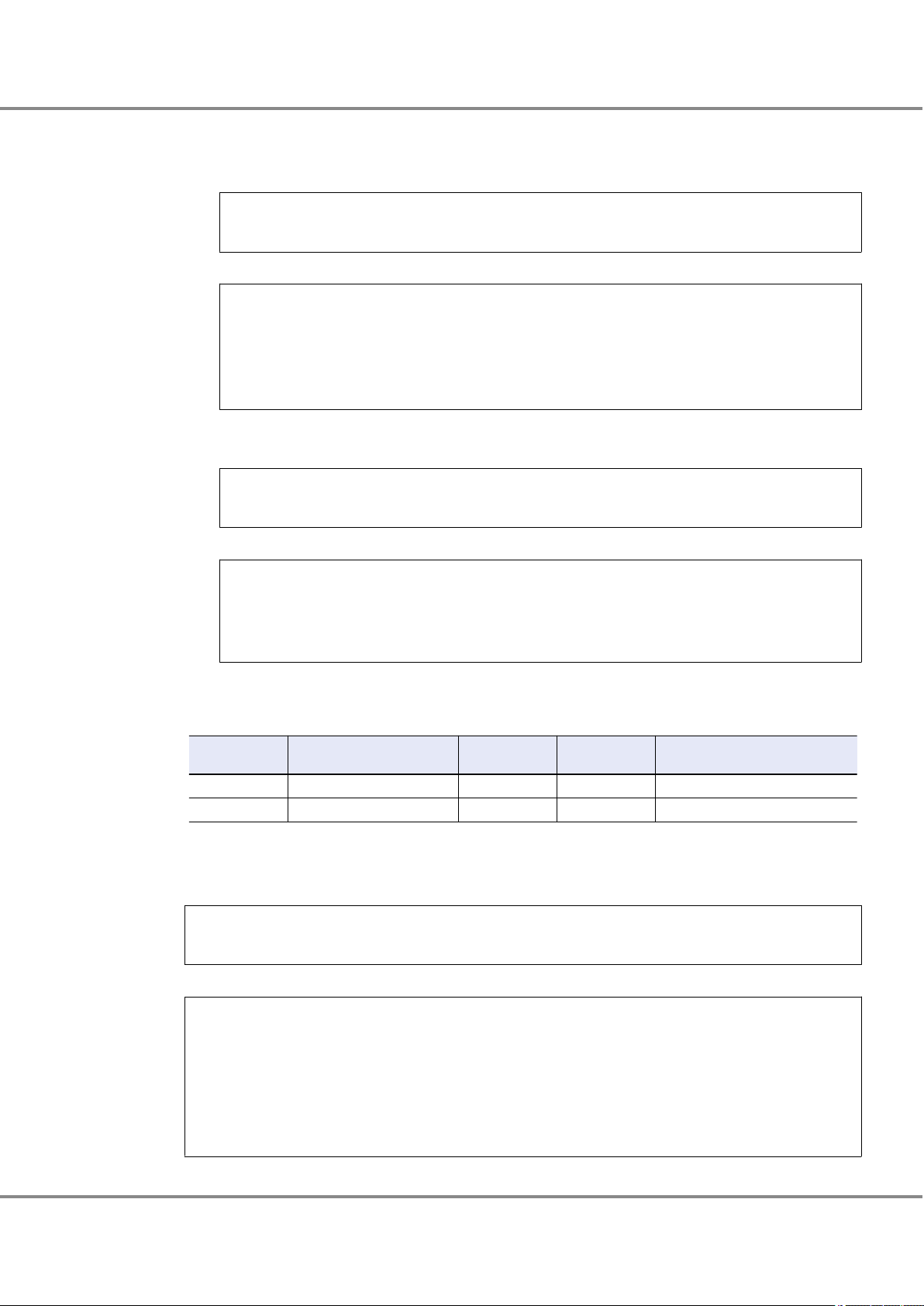
[WWN instance management table for the server]
[target binding table]
1. From the two tables,
find the same
combination of
physical slot name
and Channel
Adapter as listed in
the path route table.
SERV1_SLOT0
SERV1_SLOT1
10000000c9366046
10000000c9365d9e
lpfc0
lpfc1
Physical slot name
WWN
Instance name
16
16
CM0CA0Port0
CM1CA0Port0
202000c000cb0001
203000c000cb0001
Channel Adapter name SCSI T_ID RAID-WWN
Instance name
lpfc0
lpfc1
2. Record the
instance name
in the same row
as the physical
slot name in the
target binding table.
Chapter 2
2.3 Setting Up the Server
Setup Procedure for Emulex Fibre Channel Cards
3 Based on the connection path(s) confirmed in Step 2 and the information in the "WWN instance man-
agement table for the server", enter the instance names corresponding to the physical slot names on
the server into the "target binding table".
This completes the target binding table.
2.3.4 Setting the Configuration File
Edit the configuration file according to the "WWN instance management table for the server", "WWN instance
management table for storage system", and "target binding table". For how to set to the configuration file
and the setting example, refer to "2.5.1 For Driver Versions V6.30g and Later" (page 41) and "2.5.2 For
Driver Versions Before V6.30g" (page 47).
Check the WWN instance management table for the server, WWN instance management table for storage
system, and target binding table for any omissions.
2.3.5 Re-checking the Settings
After the settings are complete, re-check the configuration file for any incorrect settings.
Check the target binding values before rebooting the server. If the server boots with a setting error, it may
recognize a different storage system from that set in the system configuration, without generating a connection error.
FUJITSU Storage ETERNUS DX, ETERNUS AF Configuration Guide -Server Connection- (Fibre Channel) for Oracle Solaris
Copyright 2017 FUJITSU LIMITED
35
P3AM-6312-18ENZ0
Page 36

Chapter 2
2.4 Setting Up the Server to Recognize the Logical Units
Setup Procedure for Emulex Fibre Channel Cards
2.4 Setting Up the Server to Recognize the Logical Units
Make the server recognize the ETERNUS DX/AF logical units using the sd driver or hddv driver.
Skip this section if using the ETERNUS Multipath Driver or GR Multipath Driver "grmpdautoconf" command.
2.4.1 Recognizing Logical Units with the sd Driver
Make the server recognize the ETERNUS DX/AF logical units using the sd driver.
First, confirm that the logical unit settings on the ETERNUS DX/AF storage systems are correct. Next, add the
descriptions of the logical units in the sd driver's configuration file (sd.conf) to register the units.
Then reboot the server to get it to recognize the logical units.
When the Fibre Channel card driver version is V6.30g or later, skip this setting.
2.4.1.1 Logical Unit Recognition
The Emulex Fibre Channel card driver requires different settings, depending on the connection method (topology).
● For direct connection
Add the descriptions of the logical units in the sd driver configuration file (sd.conf) using a text editor, such
as "vi".
Solaris 11 OS
•
If the "/etc/driver/drv/sd.conf” file does not exist, copy the "/kernel/drv/sd.conf" file to the "/etc/driver/drv"
directory and add the line to the newly copied "sd.conf" file.
If the "/etc/driver/drv/sd.conf” file exists, do not copy over the file but instead add the line to the existing
"sd.conf" file.
Solaris 10 OS
•
Add the line to the "/kernel/drv/sd.conf" file.
Do not delete the lun=0 description for the system disk target ID.
36
FUJITSU Storage ETERNUS DX, ETERNUS AF Configuration Guide -Server Connection- (Fibre Channel) for Oracle Solaris
Copyright 2017 FUJITSU LIMITED
P3AM-6312-18ENZ0
Page 37
Chapter 2
2.4 Setting Up the Server to Recognize the Logical Units
Setup Procedure for Emulex Fibre Channel Cards
Example:
#
# Copyright (c) 1992, by Sun Microsystems, Inc.
#
#ident "@(#)sd.conf 1.9 98/01/11 SMI"
name="sd" class="scsi" class_prop="atapi"
target=0 lun=0;
name="sd" class="scsi" class_prop="atapi"
target=1 lun=0;
name="sd" class="scsi" class_prop="atapi"
target=2 lun=0;
name="sd" class="scsi" class_prop="atapi"
target=3 lun=0;
name="sd" class="scsi"
target=4 lun=0;
name="sd" parent="lpfc" target=16 lun=0;
name="sd" parent="lpfc" target=16 lun=1;
# End lpfc auto-generated configuration -- do NOT alter or delete this line
Use the "lun=" format to list all the LUNs that are to be connected.
•
Set the "target=" value the same as the Loop-ID set in the [Set CA Parameters] window of ETERNUS Web
•
GUI or ETERNUSmgr.
The ETERNUS Web GUI or ETERNUSmgr Loop-ID is natively set as a hexadecimal value, which must be
converted to a decimal value for this setting.
● For switch connection
Add the descriptions of the logical units in the sd driver configuration file (sd.conf) using a text editor, such
as "vi".
Solaris 11 OS
•
If the "/etc/driver/drv/sd.conf” file does not exist, copy the "/kernel/drv/sd.conf" file to the "/etc/driver/drv"
directory and add the line to the newly copied "sd.conf" file.
If the "/etc/driver/drv/sd.conf” file exists, do not copy over the file but instead add the line to the existing
"sd.conf" file.
Solaris 10 OS
•
Add the line to the "/kernel/drv/sd.conf" file.
Do not delete the lun=0 description for the system disk target ID.
37
FUJITSU Storage ETERNUS DX, ETERNUS AF Configuration Guide -Server Connection- (Fibre Channel) for Oracle Solaris
Copyright 2017 FUJITSU LIMITED
P3AM-6312-18ENZ0
Page 38

Chapter 2
2.4 Setting Up the Server to Recognize the Logical Units
Setup Procedure for Emulex Fibre Channel Cards
Example:
#
# Copyright (c) 1992, by Sun Microsystems, Inc.
#
#ident "@(#)sd.conf 1.9 98/01/11 SMI"
name="sd" class="scsi" class_prop="atapi"
target=0 lun=0;
name="sd" class="scsi" class_prop="atapi"
target=1 lun=0;
name="sd" class="scsi" class_prop="atapi"
target=2 lun=0;
name="sd" class="scsi" class_prop="atapi"
target=3 lun=0;
name="sd" class="scsi"
target=4 lun=0;
name="sd" parent="lpfc" target=16 lun=0;
name="sd" parent="lpfc" target=16 lun=1;
# End lpfc auto-generated configuration -- do NOT alter or delete this line
Use the "lun=" format to list all the LUNs that are to be connected.
•
For "target=", specify the target ID of the "fcp-bind-WWPN" parameter described in the configuration file in
•
"2.5.2 For Driver Versions Before V6.30g" (page 47).
The ETERNUS Web GUI or ETERNUSmgr Loop-ID is natively set as a hexadecimal value, which must be
converted to a decimal value for this setting.
2.4.1.2 Getting the Server to Recognize the Logical Units
The server now needs to use the new sd driver settings to recognize the logical units.
1 Reconfigure and reboot the server to get it to recognize the listed logical units. Execute the following
command.
# touch /reconfigure
# /usr/sbin/shutdown -y -g0 -i6
38
FUJITSU Storage ETERNUS DX, ETERNUS AF Configuration Guide -Server Connection- (Fibre Channel) for Oracle Solaris
Copyright 2017 FUJITSU LIMITED
P3AM-6312-18ENZ0
Page 39

Chapter 2
2.4 Setting Up the Server to Recognize the Logical Units
Setup Procedure for Emulex Fibre Channel Cards
2 After the server has booted up, log in as a superuser, and use the "format" command to confirm that
the storage system and all the logical units have been correctly recognized.
# format
Example 1: VTOC disk labels
• Target ID=16, lun=0 and 1 of ETERNUS DX400 S2 series are connected to the physical path "/
pci@9,600000/lpfc@1", and c4t16d0 and c4t16d1 are assigned to each of these LUNs.
• Target ID=16, lun=0 and 1 of ETERNUS DX400 S2 series are connected to the physical path "/
pci@9,600000/lpfc@2", and c5t16d0 and c5t16d1 are assigned to each of these LUNs.
# format
Searching for disks...done
c4t16d0: configured with capacity of 7.98GB
c4t16d1: configured with capacity of 7.98GB
c5t16d0: configured with capacity of 7.98GB
c5t16d1: configured with capacity of 7.98GB
AVAILABLE DISK SELECTIONS:
0. c1t0d0 <SUN36G cyl 24620 alt 2 hd 27 sec 107>
/pci@8,600000/SUNW,qlc@2/fp@0,0/ssd@w21000004cf6851ce,0
1. c4t16d0 <FUJITSU-ETERNUS_DX400 cyl 1022 alt 2 hd 64 sec 256>
/pci@9,600000/lpfc@1/sd@10,0
2. c4t16d1 <FUJITSU-ETERNUS_DX400 cyl 1022 alt 2 hd 64 sec 256>
/pci@9,600000/lpfc@1/sd@10,1
3. c5t16d0 <FUJITSU-ETERNUS_DX400 cyl 1022 alt 2 hd 64 sec 256>
/pci@9,600000/lpfc@2/sd@10,0
4. c5t16d1 <FUJITSU-ETERNUS_DX400 cyl 1022 alt 2 hd 64 sec 256>
/pci@9,600000/lpfc@2/sd@10,1
Specify disk (enter its number):
39
FUJITSU Storage ETERNUS DX, ETERNUS AF Configuration Guide -Server Connection- (Fibre Channel) for Oracle Solaris
Copyright 2017 FUJITSU LIMITED
P3AM-6312-18ENZ0
Page 40

Chapter 2
2.5 Required Driver Parameters
Setup Procedure for Emulex Fibre Channel Cards
Example 2: EFI disk labels
EFI labels are automatically assigned to 1TB and larger disks. However, even if the disk capacity is less
than 1TB, EFI labels can still be assigned using the "format -e" command, as shown in the following
example.
# format -e
Searching for disks...done
c5t16d0: configured with capacity of 3555.50GB
AVAILABLE DISK SELECTIONS:
0. c0t0d0 <FUJITSU-MAP3367NC-3701 cyl 12435 alt 2 hd 10 sec 574>
/pci@83,4000/FJSV,ulsa@2,1/sd@0,0
1. c5t16d0 <FUJITSU-ETERNUS_DX400-3.47TB>
/pci@80,4000/lpfc@3/sd@10,0
Specify disk (enter its number): 1
selecting c5t16d0
[disk formatted]
format> label
[0] SMI Label
[1] EFI Label
Specify Label type[0]: 1
Ready to label disk, continue? yes
format> quit
2.5 Required Driver Parameters
The parameters in the "/kernel/drv/lpfc.conf" configuration file need to be edited as described below.
Required parameters and values vary depending on the version of Fibre Channel card driver being used.
Original configuration file must be backed up before editing.
Example:
cp /kernel/drv/lpfc.conf ./lpfc.conf.backup
Refer to the following notes for the settings:
These settings are common for all Solaris 10 OS, Solaris 9 OS, and Solaris 8 OS versions.
•
Comment out any items that are not required by putting a "#" at the beginning of the line.
•
Instance names are specified for some items, but not for others.
•
Check the "WWN instance management table for the server" for the actual "X" instance numbers to use in
the lpfcX.
40
FUJITSU Storage ETERNUS DX, ETERNUS AF Configuration Guide -Server Connection- (Fibre Channel) for Oracle Solaris
Copyright 2017 FUJITSU LIMITED
P3AM-6312-18ENZ0
Page 41

Chapter 2 Setup Procedure for Emulex Fibre Channel Cards
2.5 Required Driver Parameters
2.5.1 For Driver Versions V6.30g and Later
Edit the configuration file according to the following parameter list.
2.5.1.1 lpfc.conf Parameter Values
Parameter
log-verbose 0x0 0x0 — —
log-only 1 1 — —
enable-auth 0 0 — —
auth-cfgparms N/A N/A — —
auth-keys N/A N/A — —
lpfcX-fcp-bind-method 4 2 Yes —
fcp-bind-WWNN Not required Not required — —
lpfcX-fcp-bind-WWPN Not required (*1) Yes —
fcp-bind-DID Not required Not required — —
lpfcX-automap 1 0 Yes
lun-queue-depth Arbitrary (*2)
tgt-queue-depth 512 512 — —
lpfcNtM-lun-throttle Not required Not required — —
lpfcNtM-tgt-throttle Not required Not required
no-device-delay 0 0 — —
network-on 0 0 — —
xmt-que-size 256 256 — —
lpfcX-scan-down 1 0 Yes —
linkdown-tmo 30 30 — —
nodev-holdio 0 0 — —
nodev-tmo 40 40 — —
delay-rsp-err 0 0 — —
num-iocbs 256 256 — —
num-bufs 128 128 — —
lpfcX-topology 4 2 Yes —
ip-class 3 3 — —
fcp-class 3 3 — —
use-adisc 0 0 — —
Setting value
(for direct connection)
(Up to 512 for each FC
port of the ETERNUS
DX/AF)
Setting value
(for switch connec-
tion)
Arbitrary (*2)
(Up to 512 for each FC
port of the ETERNUS
DX/AF)
lpfcX
(Instance name)
— —
— —
Remarks
When setting fcp-
•
bind-WWPN, set to
"0".
When not setting
•
fcp-bind-WWPN, set
to "1".
41
FUJITSU Storage ETERNUS DX, ETERNUS AF Configuration Guide -Server Connection- (Fibre Channel) for Oracle Solaris
Copyright 2017 FUJITSU LIMITED
P3AM-6312-18ENZ0
Page 42

Channel Adapter name
SCSI T-ID
RAID-WWN
Instance name
CM0CA0Port0
CM1CA0Port0
16
16
203000e000cb0001
lpfc0
lpfc1
fcp-bind-WWPN="202000e000cb0001:lpfc0t16","203000e000cb0001:lpfc1t
Chapter 2 Setup Procedure for Emulex Fibre Channel Cards
2.5 Required Driver Parameters
Setting value
(for switch connec-
tion)
lpfcX
(Instance name)
Parameter
Setting value
(for direct connection)
extra-io-tmo 0 0 — —
post-ip-buf 128 128 — —
dqfull-throttle-up-time 1 1 — —
dqfull-throttle-up-inc 1 1 — —
ack0 0 0 — —
cr-delay 0 0 — —
cr-count 1 1 — —
discovery-threads 1 1 — —
lpfcX-link-speed 2, 4, or 8 (*3) 2, 4, or 8 (*3) Yes —
fdmi-on 0 0 — —
msi-mode 3 3 — —
target-disk sd sd — —
target-tape st st — —
target-tapechanger sgen sgen — —
*1: For switch connection, set as follows:
fcp-bind-WWPN="<Storage WWPN>:<HBA instance name>t<SCSI ID>",.....
Check the target binding table for the fcp-bind-WWPN setting.
Remarks
*2: Recommended value = 512 ¸ (number of Fibre Channel ports that are connected to a single CA port) ¸
number of LUNs
(Round the result down)
Use the value of "8" if the actual result is lower.
*3: "lpfcX-link-speed" setting value
Fibre Channel
card transfer rate
(Fibre Channel switch transfer rate)
8Gbit/s 4Gbit/s 2Gbit/s FC-CA(4G) FC-CA(8G)
8Gbit/s 8 4 2 4 8
4Gbit/s 4 4 2 4 4
2Gbit/s 2 2 2 2 2
Switch connection
Direct connection
FUJITSU Storage ETERNUS DX, ETERNUS AF Configuration Guide -Server Connection- (Fibre Channel) for Oracle Solaris
Copyright 2017 FUJITSU LIMITED
42
P3AM-6312-18ENZ0
Page 43

# Copyright (c) 2003-2007 Emulex. All rights reserved.
#
# Solaris LightPulse lpfc (SCSI) / lpfn (IP) driver: global initialized data.
#
# lpfc.conf 1.54 2007/11/21 12:00:49PST
# Verbosity: only turn this flag on if you are willing to risk being
# deluged with LOTS of information.
# You can set a bit mask to record specific types of verbose messages:
#
# 0x1 ELS events
# 0x2 Device Discovery events
# 0x4 Mailbox Command events
# 0x8 Initialization events
# 0x10 Link Attention events
# 0x20 IP events
# 0x40 FCP events
# 0x80 Node table events
# 0x400 Miscellaneous events
# 0x800 SLI events
# 0x2000 IOCtl events
# 0x4000 FCP Residual Underrun events
# 0xffff Log All Events
log-verbose=0x0;
# Setting log-only to 0 causes log messages to be printed on the
# console and to be logged to syslog (which may send them to the
# console again if it's configured to do so).
# Setting log-only to 1 causes log messages to go to syslog only.
log-only=1;
# standalone parameters for fc-sp are used globally.
#
enable-auth=0;
# LWWN|RWWN|auth_tov|auth_mode|bi-dir|typelist|hashlist|dhgplist|reauth_intval
# typelist=dhchap:fcap:fcpap:kerberos
# hashlist=sha1:md5
# dhgplist=1536:null:1024:1280:2048
# For example:
# The first entry is for host-to-fabric, the second entry is for end-to-end
# auth-cfgparms="0000000000000000|FFFFFFFFFFFFFFFF|002d|02|01|01000000|02010000|040
1020305000000|0000012c";
# LWWN:type:length:pwd:RWWN:type:length:pwd
# type: 0001 ASCII 0002 Binary
# length: length of password in hex
# For example:
# auth-keys="20000000C9365947:0001:0100:11223344556677881122334455667788:2000000DEC
03ED80:0001:0100:aabbccddeeffgghhaabbccddeeffgghh";
#
# +++ Variables relating to FCP (SCSI) support. +++
#
# specifies the method of binding to be used. This
# binding method is used for persistent binding and automaped
# binding. A value of 1 will force WWNN binding, value
# of 2 will force WWPN binding, value of 3 will force
# DID binding and value of 4 will force the driver to derive
# binding from ALPA (hard addressed) in a private loop environment.
# Any persistent binding whose type does not match with the
# bind method of the port will be ignored.
#fcp-bind-method=2;
lpfc0-fcp-bind-method=2;
lpfc1-fcp-bind-method=2;
For direct connections, lpfc0-fcp-bind-method=4;
# Setup FCP persistent bindings,
# fcp-bind-WWPN binds a specific WorldWide PortName to a target id,
# fcp-bind-WWNN binds a specific WorldWide NodeName to a target id,
# fcp-bind-DID binds a specific DID to a target id.
# Binding method must match with the bind method of that HBA, else the
# binding will be ignored.
# fcp-bind-method should NOT be set to 4 when one of these binding methods
# is used.
# WWNN, WWPN and DID are hexadecimal values.
# WWNN must be 16 digit BCD with leading 0s.
# WWPN must be 16 digit BCD with leading 0s.
# DID must be 6 digit BCD with leading 0s.
Chapter 2 Setup Procedure for Emulex Fibre Channel Cards
2.5 Required Driver Parameters
2.5.1.2 /kernel/drv/lpfc.conf Example
A switch connection example is shown below.
43
FUJITSU Storage ETERNUS DX, ETERNUS AF Configuration Guide -Server Connection- (Fibre Channel) for Oracle Solaris
Copyright 2017 FUJITSU LIMITED
P3AM-6312-18ENZ0
Page 44
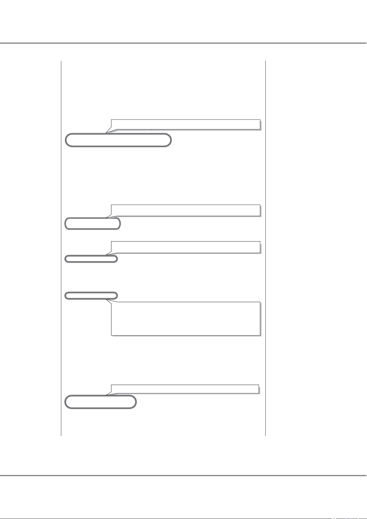
# The SCSI ID to bind to consists of two parts, the lpfc interface
# to bind to, and the target number for that interface.
# Thus lpfc0t2 specifies target 2 on interface lpfc0.
# NOTE: Target ids, with all luns supported, must also be in sd.conf.
# Here are some examples:
# WWNN SCSI ID
# fcp-bind-WWNN="2000123456789abc:lpfc1t0",
# "20000020370c27f7:lpfc0t2";
#
# WWPN SCSI ID
# fcp-bind-WWPN="2100123456789abc:lpfc0t0",
# "21000020370c2855:lpfc0t1",
# "2100122222222222:lpfc2t2nd-WWPN="2100123456789abc:lpfc0t0",
# "21000020370c2855:lpfc0t1",";
#
fcp-bind-WWPN="500000e0d0100386:lpfc0t16",
"500000e0d0100306:lpfc1t16";
# DID SCSI ID
# fcp-bind-DID="0000ef:lpfc0t3";
# BEGIN: LPUTIL-managed Persistent Bindings
# If automap is set, SCSI IDs for all FCP nodes without
# persistent bindings will be automatically generated.
# If new FCP devices are added to the network when the system is down,
# there is no guarantee that these SCSI IDs will remain the same
# when the system is booted again.
# The bind method of the port is used as the binding method of
# automap devices to preserve SCSI IDs between link down and link up.
# If automap is 0, only devices with persistent bindings will be
# recognized by the system.
#automap=1;
#automap=0;
lpfc0-automap=0;
lpfc1-automap=0;
# lun-queue-depth [1 to 128] - The default value lpfc will use to
# limit the number of outstanding commands per FCP LUN. This value
# is global, affecting each LUN recognized by the driver, but may be
# overridden on a per-LUN basis (see below). RAID arrays may want
# to be configured using the per-LUN tunable throttles.
lun-queue-depth=20;
# tgt-queue-depth [0 to 10240] - The default value lpfc will use to
# limit the number of outstanding commands per FCP target. This value
# is global, affecting each target recognized by the driver, but may be
# overridden on a per-target basis (see below). RAID arrays may want
# to be configured using the per-target tunable throttles. A value
# of 0 means don't throttle the target.
tgt-queue-depth=512;
# lpfcNtM-lun-throttle: the maximum number of outstanding commands to
# permit for each LUN of an FCP target that supports multiple LUNs.
# The default throttle for the number of commands outstanding to a single
# LUN of a multiple-LUN target is lun-queue-depth. For a target that
For direct connections, lpfc0-automap=1;
For both direct connections and switch connections, add this setting.
For an ETERNUS DX60 S2/DX80 S2/DX90 S2, this setting is not required.
For direct connections, this setting is not required.
# can support multiple LUNs, it may be useful to specify a LUN throttle
# that differs from the default.
# Example: lpfc0t17-lun-throttle=48;
# says that each LUN on target 17, interface lpfc0 should be allowed
# up to 48 simultaneously outstanding commands.
#lpfc1t39-lun-throttle=10;
#lpfc0t40-lun-throttle=30;
# lpfcNtM-tgt-throttle: the maximum number of outstanding commands to
# permit for a FCP target.
# By default, target throttle is disabled.
# Example: lpfc0t17-tgt-throttle=48;
# says that target 17, interface lpfc0 should be allowed
# up to 48 simultaneously outstanding commands.
#lpfc1t39-tgt-throttle=10;
#lpfc0t40-tgt-throttle=30;
lpfc0t16-tgt-throttle=40;
lpfc1t16-tgt-throttle=40;
# no-device-delay [0 to 30] - determines the length of
# the interval between deciding to fail back an I/O because there is no way
# to communicate with its particular FCP device (e.g., due to device failure)
# and the actual fail back. A value of zero implies no delay whatsoever.
# Cautions: (1) This value is in seconds.
For an ETERNUS DX60 S2/DX80 S2/DX90 S2, this setting is required.
For both direct connections and switch connections, add this setting.
For models shown below, confirm that the value is set to "512".
࣭
ETERNUS DX400 S2 series
࣭
ETERNUS DX8000 S2 series
For models shown below, this setting is not required.
࣭
ETERNUS DX60 S2/DX80 S2/DX90 S2
Chapter 2 Setup Procedure for Emulex Fibre Channel Cards
2.5 Required Driver Parameters
FUJITSU Storage ETERNUS DX, ETERNUS AF Configuration Guide -Server Connection- (Fibre Channel) for Oracle Solaris
Copyright 2017 FUJITSU LIMITED
44
P3AM-6312-18ENZ0
Page 45

# (2) Setting a long delay value may permit I/O to build up,
# each with a pending timeout, which could result in the exhaustion of
# critical Solaris kernel resources. In this case, you may see a fatal
# message such as
# PANIC: Timeout table overflow
#
# Note that this value can have an impact on the speed with which a
# system can shut down with I/Os pending and with the HBA not able to
# communicate with the loop or fabric, e.g., with a cable pulled.
#no-device-delay=1;
no-device-delay=0;
#
# +++ Variables relating to IP networking support. +++
#
# network-on: true (1) if networking is enabled, false (0) if not
# This variable will be set during the installation of the driver
# via pkgadd.
network-on=0;
# xmt-que-size [128 to 10240] - size of the transmit queue for mbufs
xmt-que-size=256;
#
# +++ Variables common to both SCSI (FCP) and IP networking support. +++
#
#
# If scan-down = 0, scan the devices on the private loop in increasing
# order of ALPA. If scan-down = 1, scan the devices on the private loop
# in decreasing order of ALPA.
# NOTE: scan-down does not apply if a loop map is obtained.
#
#scan-down=1;
lpfc0-scan-down=0;
lpfc1-scan-down=0;
# Determine how long the driver will wait [0 - 255] to begin linkdown
# processing when the hba link has become inaccessible. Linkdown processing
# includes failing back commands that have been waiting for the link to
# come back up. Units are in seconds. linkdown-tmo works in conjunction
# with nodev-tmo. I/O will fail when either of the two expires.
lpfc0-linkdown-tmo=30;
lpfc1-linkdown-tmo=30;
For direct connections, lpfc0-scan-down=1;
For both direct connections and switch connections, add this setting.
Confirm that the value is "0". If not, set the value to "0".
# If set, nodev-holdio will hold all I/O errors on FCP devices that disappear
# until they come back. Default is 0, return errors with no-device-delay.
# This parameter is ignored, if scsi commands are issued in polled mode.
nodev-holdio=0;
# If set, nodev-tmo will hold all I/O errors on devices that disappear
# until the timer [0 to 255 secs] expires. Default is 30, return errors
# with no-device-delay.
#nodev-tmo=30;
nodev-tmo=40;
# Use no-device-delay to delay FCP RSP errors and certain check conditions.
delay-rsp-err=0;
# num-iocbs [128 to 10240] - number of iocb buffers to allocate
num-iocbs=256;
# num-bufs [64 to 4096] - number of buffers to allocate
# Buffers are needed to support Fibre channel Extended Link Services.
# Also used for SLI-2 FCP buffers, one per FCP command, and Mailbox commands.
num-bufs=128;
# topology: link topology for initializing the Fibre Channel connection.
# 0 = attempt loop mode, if it fails attempt point-to-point mode
# 2 = attempt point-to-point mode only
# 4 = attempt loop mode only
# Set point-to-point mode if you want to run as an N_Port.
# Set loop mode if you want to run as an NL_Port.
#topology=0;
lpfc0-topology=2;
lpfc1-topology=2;
For direct connections, lpfc0-topology=4;
For both direct connections and switch connections, add this setting.
Confirm that the value is "40". If not, set the value to "40".
# Set a preferred ALPA for the adapter, only valid if topology is loop.
# lpfc0-assign-alpa=2; Request ALPA 2 for lpfc0
Chapter 2 Setup Procedure for Emulex Fibre Channel Cards
2.5 Required Driver Parameters
FUJITSU Storage ETERNUS DX, ETERNUS AF Configuration Guide -Server Connection- (Fibre Channel) for Oracle Solaris
Copyright 2017 FUJITSU LIMITED
45
P3AM-6312-18ENZ0
Page 46

# ip-class: FC class (2 or 3) to use for the IP protocol.
ip-class=3;
# fcp-class: FC class (2 or 3) to use for the FCP protocol.
fcp-class=3;
# Use ADISC for FCP rediscovery instead of PLOGI.
use-adisc=0;
# Extra IO timeout [0 to 255 secs] for fabrics
extra-io-tmo=0;
# Number of 4k STREAMS buffers [64 to 1024] to post to IP ring.
post-ip-buf=128;
# Use dqfull-throttle-up-time [0 to 30 secs] to specify when to increment
# the current Q depth.
dqfull-throttle-up-time=1;
# Increment the current Q depth by dqfull-throttle-up-inc [0 to 128]
dqfull-throttle-up-inc=1;
# Use ACK0, instead of ACK1 for class 2 acknowledgement.
ack0=0;
# cr-delay: Coalesce Response Delay
# This value specifies a count of milliseconds [0 to 63] after which an
# interrupt response is generated if cr-count has not been satisfied.
# This value is set to 0 to disable the Coalesce Response feature.
cr-delay=0;
# cr-count: Coalesce Response Count
# This value specifies a count of I/O completions [1 to 255] after which an
# interrupt response is generated. This feature is disabled if cr-delay is
# set to 0.
cr-count=1;
For both direct connections and switch connections, add this setting.
Confirm that the value is "3". If not, set the value to "3".
For both direct connections and switch connections, add this setting.
Confirm that the value is "3". If not, set the value to "3".
# discovery-threads [1 to 32] - This value specifies the maximum number of
# ELS commands during discovery
discovery-threads=1;
# link-speed: link speed selection for initializing the Fibre Channel connection.
# 0 = auto select (default)
# 1 = 1 Gigabaud
# 2 = 2 Gigabaud
# 4 = 4 Gigabaud
# 8 = 8 Gigabaud
#link-speed=0;
lpfc0-link-speed=8;
lpfc1-link-speed=8;
# fdmi-on: 0 = disable fdmi
# 1 = enable fdmi without registration of "host name" port attribute
# 2 = enable fdmi and "host name" port attribute
fdmi-on=0;
# msi-mode: 0 = disable msi; use legacy interrupts
# 1 = enable single message MSI
# 2 = enable multiple message MSI
# 3 = auto select (default)
msi-mode=3;
# Setup FCP device to target driver associations
target-disk="sd";
target-tape="st";
target-tapechanger="sgen";
For both direct connections and switch connections, add these settings.
Chapter 2 Setup Procedure for Emulex Fibre Channel Cards
2.5 Required Driver Parameters
FUJITSU Storage ETERNUS DX, ETERNUS AF Configuration Guide -Server Connection- (Fibre Channel) for Oracle Solaris
Copyright 2017 FUJITSU LIMITED
46
P3AM-6312-18ENZ0
Page 47

Chapter 2 Setup Procedure for Emulex Fibre Channel Cards
2.5 Required Driver Parameters
2.5.2 For Driver Versions Before V6.30g
Edit the configuration file according to the following parameter list.
2.5.2.1 lpfc.conf Parameter Values
Parameter
log-verbose 0x0 0x0 — —
log-only 1 1 — —
lpfcX-fcp-bind-method 4 2 Yes An instance name is
fcp-bind-WWNN Not required Not required — —
fcp-bind-WWPN Not required (*1) — —
fcp-bind-DID Not required Not required — —
lpfcX-automap 1 0 Yes An instance name is
lun-queue-depth
tgt-queue-depth
lpfcNtM-lun-throttle Not required Not required — —
lpfcNtM-tgt-throttle
no-device-delay 0 0 — —
network-on 0 0 — —
Setting value
(for direct connection)
For the ETERNUS
•
DX60 S2/DX80 S2/
DX90 S2: Not required
For the ETERNUS
•
DX400 S2 series and
the ETERNUS DX8000
S2 series: 20
For the ETERNUS
•
DX60 S2/DX80 S2/
DX90 S2: Not required
For the ETERNUS
•
DX400 S2 series and
the ETERNUS DX8000
S2 series: 512
For the ETERNUS
•
DX60 S2/DX80 S2/
DX90 S2: 40
For the ETERNUS
•
DX400 S2 series and
the ETERNUS DX8000
S2 series: Not required
Setting value
(for switch connec-
tion)
For the ETERNUS
•
DX60 S2/DX80 S2/
DX90 S2: Not required
For the ETERNUS
•
DX400 S2 series and
the ETERNUS DX8000
S2 series: 20
For the ETERNUS
•
DX60 S2/DX80 S2/
DX90 S2: Not required
For the ETERNUS
•
DX400 S2 series and
the ETERNUS DX8000
S2 series: 512
For the ETERNUS
•
DX60 S2/DX80 S2/
DX90 S2:
40 ¸ (No. of Serverside Fibre Channel
ports connected to
each ETERNUS-side
CA port) (Round the
result down)
Use the value of "8" if
the actual result is
lower.
For the ETERNUS
•
DX400 S2 series and
the ETERNUS DX8000
S2 series: Not required
lpfcX
(Instance name)
— —
— —
—
Remarks
specified for each instance.
specified for each instance.
—
47
FUJITSU Storage ETERNUS DX, ETERNUS AF Configuration Guide -Server Connection- (Fibre Channel) for Oracle Solaris
Copyright 2017 FUJITSU LIMITED
P3AM-6312-18ENZ0
Page 48

Channel Adapter name
SCSI T-ID
RAID-WWN
Instance name
CM0CA0Port0
CM1CA0Port0
16
16
203000e000cb0001
lpfc0
lpfc1
fcp-bind-WWPN="202000e000cb0001:lpfc0t16","203000e000cb0001:lpfc1t
Chapter 2 Setup Procedure for Emulex Fibre Channel Cards
2.5 Required Driver Parameters
Setting value
(for switch connec-
tion)
lpfcX
(Instance name)
Remarks
Parameter
Setting value
(for direct connection)
xmt-que-size 256 256 — —
lpfcX-scan-down 1 0 Yes An instance name is
specified for each instance.
linkdown-tmo 30 30 — —
nodev-holdio 0 0 — —
nodev-tmo 40 40 — —
delay-rsp-err 0 0 — —
num-iocbs 256 256 — —
num-bufs 128 128 — —
lpfcX-topology 4 2 Yes An instance name is
specified for each instance.
ip-class 3 3 — —
fcp-class 3 3 — —
use-adisc 0 0 — —
extra-io-tmo 0 0 — —
post-ip-buf 128 128 — —
dqfull-throttle-up-time 1 1 — —
dqfull-throttle-up-inc 1 1 — —
ack0 0 0 — —
cr-delay 0 0 — —
cr-count 1 1 — —
discovery-threads 1 1 — —
lpfcX-link-speed 2 or 4
(*2)
1, 2, or 4
(*2)
Yes An instance name is
specified for each instance.
fdmi-on 0 0 — —
*1: For switch connection, set as follows:
fcp-bind-WWPN="<Storage WWPN>:<HBA instance name>t<SCSI ID>",.....
Check the target binding table for the fcp-bind-WWPN setting.
*2: "lpfcX-link-speed" setting value
Fibre Channel card transfer rate
4Gbit/s 4 4 2 1 4
FUJITSU Storage ETERNUS DX, ETERNUS AF Configuration Guide -Server Connection- (Fibre Channel) for Oracle Solaris
Switch connection
(Fibre Channel switch transfer rate)
8Gbit/s 4Gbit/s 2Gbit/s 1Gbit/s
Copyright 2017 FUJITSU LIMITED
Direct connection
48
P3AM-6312-18ENZ0
Page 49

Chapter 2 Setup Procedure for Emulex Fibre Channel Cards
2.5 Required Driver Parameters
Fibre Channel card transfer rate
2Gbit/s 2 2 2 1 2
Switch connection
(Fibre Channel switch transfer rate)
8Gbit/s 4Gbit/s 2Gbit/s 1Gbit/s
Direct connection
49
FUJITSU Storage ETERNUS DX, ETERNUS AF Configuration Guide -Server Connection- (Fibre Channel) for Oracle Solaris
Copyright 2017 FUJITSU LIMITED
P3AM-6312-18ENZ0
Page 50

#
# Copyright (c) 2005, Emulex
# 3333 Susan Street, Costa Mesa, CA 92626
#
# All rights reserved. This computer program and related documentation
# is protected by copyright and distributed under licenses restricting
# its use, copying, distribution and decompilation. This computer
# program and its documentation are CONFIDENTIAL and a TRADE SECRET
# of Emulex Design & Manufacturing Corporation. The receipt or possession
# of this program or its documentation does not convey rights to reproduce
# or disclose its contents, or to manufacture, use, or sell anything that
# it may describe, in whole or in part, without the specific written consent
# of Emulex Design & Manufacturing Corporation. Any reproduction of this
# program without the express written consent of Emulex Design & Manufacturing
# Corporation is a violation of the copyright laws and may subject you to
# criminal prosecution.
#
#
# Solaris LightPulse lpfc (SCSI) / lpfn (IP) driver: global initialized data.
#
# lpfc.conf 1.29.1.2 2005/10/21 11:06:55PDT
# Verbosity: only turn this flag on if you are willing to risk being
# deluged with LOTS of information.
# You can set a bit mask to record specific types of verbose messages:
#
# 0x1 ELS events
# 0x2 Device Discovery events
# 0x4 Mailbox Command events
# 0x8 Initialization events
# 0x10 Link Attention events
# 0x20 IP events
# 0x40 FCP events
# 0x80 Node table events
# 0x400 Miscellaneous events
# 0x800 SLI events
# 0x2000 IOCtl events
# 0xffff Log All Events
log-verbose=0x0;
# Setting log-only to 0 causes log messages to be printed on the
# console and to be logged to syslog (which may send them to the
# console again if it's configured to do so).
# Setting log-only to 1 causes log messages to go to syslog only.
log-only=1;
#
# +++ Variables relating to FCP (SCSI) support. +++
#
# specifies the method of binding to be used. This
# binding method is used for persistent binding and automaped
# binding. A value of 1 will force WWNN binding, value
# of 2 will force WWPN binding, value of 3 will force
# DID binding and value of 4 will force the driver to derive
# binding from ALPA (hard addressed) in a private loop environment.
# Any persistent binding whose type does not match with the
# bind method of the port will be ignored.
lpfc0-fcp-bind-method=2;
lpfc1-fcp-bind-method=2;
# Setup FCP persistent bindings,
# fcp-bind-WWPN binds a specific WorldWide PortName to a target id,
# fcp-bind-WWNN binds a specific WorldWide NodeName to a target id,
# fcp-bind-DID binds a specific DID to a target id.
# Binding method must match with the bind method of that HBA, else the
# binding will be ignored.
# fcp-bind-method should NOT be set to 4 when one of these binding methods
# is used.
# WWNN, WWPN and DID are hexadecimal values.
# WWNN must be 16 digit BCD with leading 0s.
# WWPN must be 16 digit BCD with leading 0s.
# DID must be 6 digit BCD with leading 0s.
# The SCSI ID to bind to consists of two parts, the lpfc interface
# to bind to, and the target number for that interface.
# Thus lpfc0t2 specifies target 2 on interface lpfc0.
# NOTE: Target ids, with all luns supported, must also be in sd.conf.
# Here are some examples:
# WWNN SCSI ID
For direct connections, lpfc0-fcp-bind-method=4;
Chapter 2 Setup Procedure for Emulex Fibre Channel Cards
2.5 Required Driver Parameters
2.5.2.2 /kernel/drv/lpfc.conf Example
A switch connection example is shown below.
50
FUJITSU Storage ETERNUS DX, ETERNUS AF Configuration Guide -Server Connection- (Fibre Channel) for Oracle Solaris
Copyright 2017 FUJITSU LIMITED
P3AM-6312-18ENZ0
Page 51
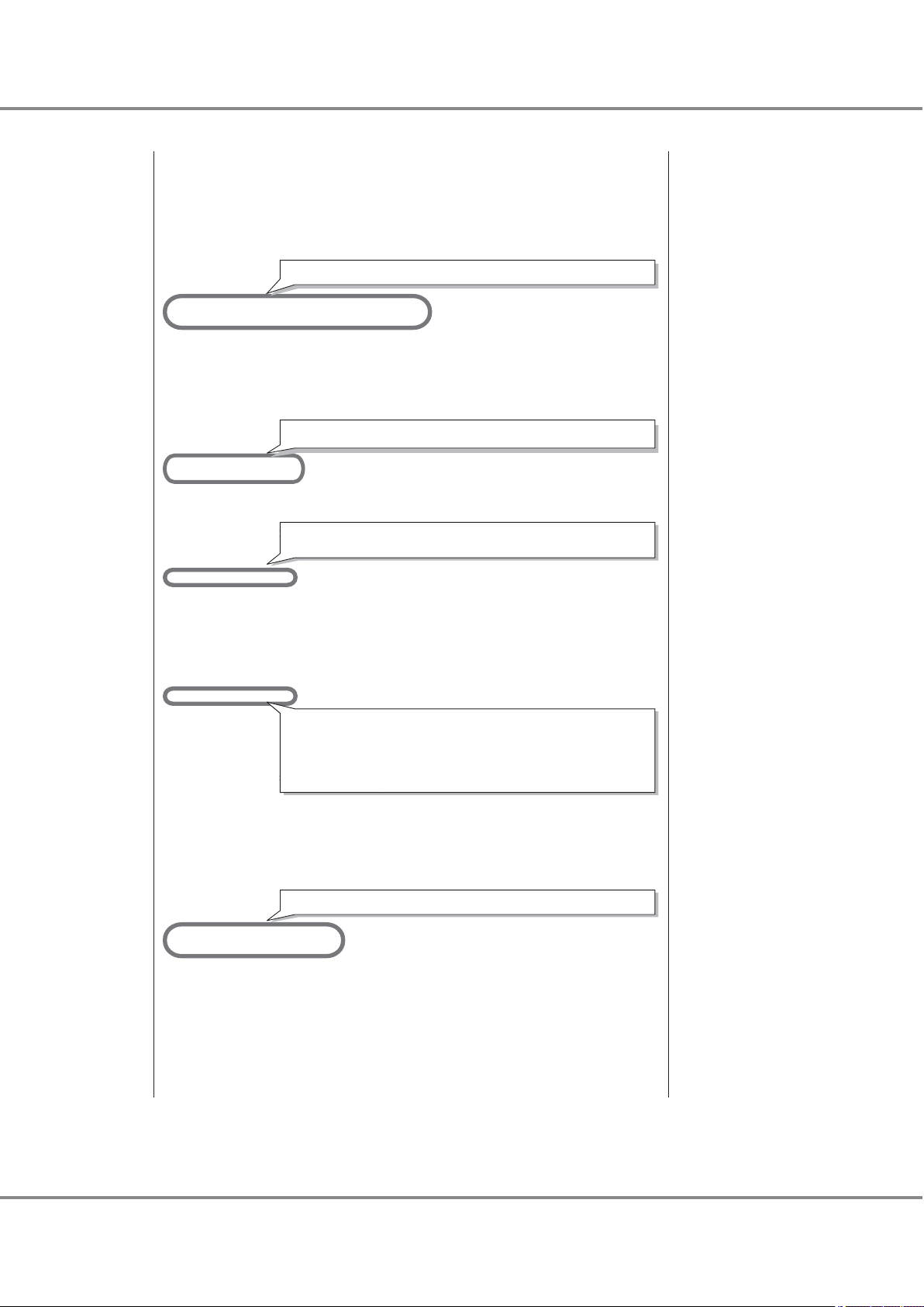
# fcp-bind-WWNN="2000123456789abc:lpfc1t0",
# "20000020370c27f7:lpfc0t2";
#
# WWPN SCSI ID
# fcp-bind-WWPN="2100123456789abc:lpfc0t0",
# "21000020370c2855:lpfc0t1",
# "2100122222222222:lpfc2t2";
#
# DID SCSI ID
# fcp-bind-DID="0000ef:lpfc0t3";
# BEGIN: LPUTIL-managed Persistent Bindings
fcp-bind-WWPN="2141000b5d6a0109:lpfc0t16",
"2140000b5d6a0109:lpfc1t16";
# If automap is set, SCSI IDs for all FCP nodes without
# persistent bindings will be automatically generated.
# If new FCP devices are added to the network when the system is down,
# there is no guarantee that these SCSI IDs will remain the same
# when the system is booted again.
# The bind method of the port is used as the binding method of
# automap devices to preserve SCSI IDs between link down and link up.
# If automap is 0, only devices with persistent bindings will be
# recognized by the system.
lpfc0-automap=0;
lpfc1-automap=0;ࠉ
# lun-queue-depth [1 to 128] - The default value lpfc will use to
# limit the number of outstanding commands per FCP LUN. This value
# is global, affecting each LUN recognized by the driver, but may be
# overridden on a per-LUN basis (see below). RAID arrays may want
# to be configured using the per-LUN tunable throttles.
#lun-queue-depth=30;
lun-queue-depth=20;
# tgt-queue-depth [0 to 10240] - The default value lpfc will use to
# limit the number of outstanding commands per FCP target. This value
# is global, affecting each target recognized by the driver, but may be
# overridden on a per-target basis (see below). RAID arrays may want
# to be configured using the per-target tunable throttles. A value
# of 0 means don't throttle the target.
#tgt-queue-depth=0;
tgt-queue-depth=512;
# lpfcNtM-lun-throttle: the maximum number of outstanding commands to
# permit for each LUN of an FCP target that supports multiple LUNs.
# The default throttle for the number of commands outstanding to a single
# LUN of a multiple-LUN target is lun-queue-depth. For a target that
# can support multiple LUNs, it may be useful to specify a LUN throttle
# that differs from the default.
# Example: lpfc0t17-lun-throttle=48;
# says that each LUN on target 17, interface lpfc0 should be allowed
# up to 48 simultaneously outstanding commands.
#lpfc1t39-lun-throttle=10;
#lpfc0t40-lun-throttle=30;
# lpfcNtM-tgt-throttle: the maximum number of outstanding commands to
# permit for a FCP target.
# By default, target throttle is disabled.
# Example: lpfc0t17-tgt-throttle=48;
# says that target 17, interface lpfc0 should be allowed
# up to 48 simultaneously outstanding commands.
#lpfc1t39-tgt-throttle=10;
#lpfc0t40-tgt-throttle=30;
# no-device-delay [0 to 30] - determines the length of
# the interval between deciding to fail back an I/O because there is no way
# to communicate with its particular FCP device (e.g., due to device failure)
# and the actual fail back. A value of zero implies no delay whatsoever.
# Cautions: (1) This value is in seconds.
# (2) Setting a long delay value may permit I/O to build up,
# each with a pending timeout, which could result in the exhaustion of
# critical Solaris kernel resources. In this case, you may see a fatal
# message such as
# PANIC: Timeout table overflow
#
For direct connections, this setting is not required.
For both direct connections and switch connections, add this setting.
For direct connections, lpfc0-automap=1;
For an ETERNUS DX60 S2/DX80 S2/DX90 S2, this setting is not required.
For an ETERNUS DX60 S2/DX80 S2/DX90 S2, this setting is required.
For both direct connections and switch connections, add this setting.
For models shown below, confirm that the value is set to "512".
㺃ETERNUS DX400 S2 series
㺃ETERNUS DX8000 S2 series
For models shown below, this setting is not required.
㺃ETERNUS DX60 S2/DX80 S2/DX90 S2
Chapter 2 Setup Procedure for Emulex Fibre Channel Cards
2.5 Required Driver Parameters
FUJITSU Storage ETERNUS DX, ETERNUS AF Configuration Guide -Server Connection- (Fibre Channel) for Oracle Solaris
Copyright 2017 FUJITSU LIMITED
51
P3AM-6312-18ENZ0
Page 52

# Note that this value can have an impact on the speed with which a
# system can shut down with I/Os pending and with the HBA not able to
# communicate with the loop or fabric, e.g., with a cable pulled.
no-device-delay=0;ࠉ
#
# +++ Variables relating to IP networking support. +++
#
# network-on: true (1) if networking is enabled, false (0) if not
# This variable will be set during the installation of the driver
# via pkgadd.
network-on=0;
# xmt-que-size [128 to 10240] - size of the transmit queue for mbufs
xmt-que-size=256;
#
# +++ Variables common to both SCSI (FCP) and IP networking support. +++
#
#
# If scan-down = 0, scan the devices on the private loop in increasing
# order of ALPA. If scan-down = 1, scan the devices on the private loop
# in decreasing order of ALPA.
# NOTE: scan-down does not apply if a loop map is obtained.
#
lpfc0-scan-down=0;
lpfc1-scan-down=0;
# Determine how long the driver will wait [0 - 255] to begin linkdown
# processing when the hba link has become inaccessible. Linkdown processing
# includes failing back commands that have been waiting for the link to
# come back up. Units are in seconds. linkdown-tmo works in conjunction
# with nodev-tmo. I/O will fail when either of the two expires.
linkdown-tmo=30;
# If set, nodev-holdio will hold all I/O errors on FCP devices that disappear
# until they come back. Default is 0, return errors with no-device-delay.
# This parameter is ignored, if scsi commands are issued in polled mode.
nodev-holdio=0;
# If set, nodev-tmo will hold all I/O errors on devices that disappear
# until the timer [0 to 255 secs] expires. Default is 30, return errors
# with no-device-delay.
nodev-tmo=40; ࠉ
# Use no-device-delay to delay FCP RSP errors and certain check conditions.
delay-rsp-err=0;
# num-iocbs [128 to 10240] - number of iocb buffers to allocate
num-iocbs=256;
# num-bufs [64 to 4096] - number of buffers to allocate
# Buffers are needed to support Fibre channel Extended Link Services.
# Also used for SLI-2 FCP buffers, one per FCP command, and Mailbox commands.
num-bufs=128;
# topology: link topology for initializing the Fibre Channel connection.
# 0 = attempt loop mode, if it fails attempt point-to-point mode
# 2 = attempt point-to-point mode only
# 4 = attempt loop mode only
# 6 = attempt point-to-point mode, if it fails attempt loop mode
# Set point-to-point mode if you want to run as an N_Port.
# Set loop mode if you want to run as an NL_Port.
lpfc0-topology=2;
lpfc1-topology=2;
# Set a preferred ALPA for the adapter, only valid if topology is loop.
# lpfc0-assign-alpa=2; Request ALPA 2 for lpfc0
# ip-class: FC class (2 or 3) to use for the IP protocol.
ip-class=3;
For direct connections, lpfc0-scan-down=1;
For both direct connections and switch connections, add this setting.
Confirm that the value is "0". If it is not, change it to "0".
For both direct connections and switch connections, add this setting.
Confirm that the value is "40". If it is not, change it to "40".
For direct connections, lpfc0-topology=4;
For both direct connections and switch connections, add this setting.
Confirm that the value is "3". If it is not, change it to "3".
Chapter 2 Setup Procedure for Emulex Fibre Channel Cards
2.5 Required Driver Parameters
FUJITSU Storage ETERNUS DX, ETERNUS AF Configuration Guide -Server Connection- (Fibre Channel) for Oracle Solaris
Copyright 2017 FUJITSU LIMITED
52
P3AM-6312-18ENZ0
Page 53

# fcp-class: FC class (2 or 3) to use for the FCP protocol.
fcp-class=3; ࠉ
# Use ADISC for FCP rediscovery instead of PLOGI.
use-adisc=0;
# Extra IO timeout [0 to 255 secs] for fabrics
extra-io-tmo=0;
# Number of 4k STREAMS buffers [64 to 1024] to post to IP ring.
post-ip-buf=128;
# Use dqfull-throttle-up-time [0 to 30 secs] to specify when to increment
# the current Q depth.
dqfull-throttle-up-time=1;
# Increment the current Q depth by dqfull-throttle-up-inc [0 to 128]
dqfull-throttle-up-inc=1;
# Use ACK0, instead of ACK1 for class 2 acknowledgement.
ack0=0;
# cr-delay: Coalesce Response Delay
# This value specifies a count of milliseconds [0 to 63] after which an
# interrupt response is generated if cr-count has not been satisfied.
# This value is set to 0 to disable the Coalesce Response feature.
cr-delay=0;
# cr-count: Coalesce Response Count
# This value specifies a count of I/O completions [1 to 255] after which an
# interrupt response is generated. This feature is disabled if cr-delay is
# set to 0.
cr-count=1;
# discovery-threads [1 to 32] - This value specifies the maximum number of
# ELS commands during discovery
discovery-threads=1;
# link-speed: link speed selection for initializing the Fibre Channel connection.
# 0 = auto select (default)
# 1 = 1 Gigabaud
# 2 = 2 Gigabaud
# 4 = 4 Gigabaud
lpfc0-link-speed=2;
lpfc1-link-speed=2;
# fdmi-on: 0 = disable fdmi
# 1 = enable fdmi without registration of "host name" port attribute
# 2 = enable fdmi and "host name" port attribute
fdmi-on=0;
# Used only by i386 FCP (SCSI)
# flow_control="duplx" queue="qfifo" disk="scdk" tape="sctp";
#
For both direct connections and switch connections, add this setting.
Confirm that the value is "3". If it is not, change it to "3".
For both direct connections and switch connections, add these settings.
Chapter 2 Setup Procedure for Emulex Fibre Channel Cards
2.5 Required Driver Parameters
53
FUJITSU Storage ETERNUS DX, ETERNUS AF Configuration Guide -Server Connection- (Fibre Channel) for Oracle Solaris
Copyright 2017 FUJITSU LIMITED
P3AM-6312-18ENZ0
Page 54

Chapter 3
Setup Procedure for QLogic Fibre Channel Cards
This chapter describes the procedures for "Installing the Driver and Setting Up the Server" and "Recognizing
the Logical Units" required to establish a connection between a server with QLogic Fibre Channel cards and
an ETERNUS DX/AF.
3.1 Workflow
Workflow
Installing the Fibre Channel Card Driver
Install the driver. Download the proper driver from the QLogic web-site as required.
"3.2 Installing the Fibre Channel Card Driver" (page 55)
•
Driver (downloaded from web-site)
•
Driver product manual
•
Used for driver installation
•
"SANsurfer FC HBA CLI Application" (downloaded from web-site)
-
Creating Various Management Tables
Enter the necessary information in the "WWN Instance Management Table for the Server", "WWN Instance Management Table for Storage System", and "Target Binding Table".
"3.3 Setting Up the Server" (page 55)
•
"Appendix A Various Management Table Templates" (page 82)
•
Editing the Configuration File
Set the driver parameters by editing the configuration file.
"3.3 Setting Up the Server" (page 55)
•
"3.5 Required Driver Parameters" (page 66)
•
54
FUJITSU Storage ETERNUS DX, ETERNUS AF Configuration Guide -Server Connection- (Fibre Channel) for Oracle Solaris
Copyright 2017 FUJITSU LIMITED
P3AM-6312-18ENZ0
Page 55

Chapter 3
3.2 Installing the Fibre Channel Card Driver
Setup Procedure for QLogic Fibre Channel Cards
Setting Up the Server to Recognize the Logical Units (LUNs)
Make the server recognize the ETERNUS DX/AF logical units using the sd driver.
"3.4 Setting Up the Server to Recognize the Logical Units" (page 63)
•
After completing all the required procedures in this manual, proceed to "Setting the Multipaths" in
"Configuration Guide -Server Connection- (Fibre Channel) for Oracle Solaris".
3.2 Installing the Fibre Channel Card Driver
Use the following procedure to install the Fibre Channel card driver.
1 Download and install the appropriate driver from the QLogic web-site:
http://www.qlogic.com (QLogic web-site)
Installation procedures should be available with the driver.
2 Download and install the "SANsurfer FC HBA CLI Application" from the QLogic web-site.
3.3 Setting Up the Server
The server setup will vary according to how the ETERNUS DX/AF storage systems and server are to be connected. Edit the server's configuration file to match the chosen topology. Configuration files may also differ depending on which Fibre Channel cards are to be used.
There are two possible connection topologies: direct connection and switch connection.
● For direct connection
Instance name data of the Fibre Channel card is necessary. Refer to the following sections to set.
"3.3.1 Creating a WWN Instance Management Table for the Server" (page 56)
•
"3.3.2 Creating a WWN Instance Management Table for Storage System" (page 60)
•
"3.3.4 Setting the Configuration File" (page 62)
•
"3.3.5 Re-checking the Settings" (page 62)
•
55
FUJITSU Storage ETERNUS DX, ETERNUS AF Configuration Guide -Server Connection- (Fibre Channel) for Oracle Solaris
Copyright 2017 FUJITSU LIMITED
P3AM-6312-18ENZ0
Page 56

Chapter 3
3.3 Setting Up the Server
Setup Procedure for QLogic Fibre Channel Cards
● For switch connection
The Fibre Channel card Instance name, target WWN, and target ID information are necessary. Check each
item and enter them in the table. Edit the configuration file according to those information and make settings. Refer to the following sections to set.
"3.3.1 Creating a WWN Instance Management Table for the Server" (page 56)
•
"3.3.2 Creating a WWN Instance Management Table for Storage System" (page 60)
•
"3.3.3 Creating a Target Binding Table" (page 61)
•
"3.3.4 Setting the Configuration File" (page 62)
•
"3.3.5 Re-checking the Settings" (page 62)
•
3.3.1 Creating a WWN Instance Management Table for the Server
Create a "WWN instance management table for the server" with information regarding the Fibre Channel
card.
Determine the following information for each Fibre Channel card installed in the server and enter it into a
copy of the "WWN instance management table for the server". (found in "Appendix A Various Management
Table Templates" (page 82)).
Physical slot name
•
WWN
•
Instance name
•
Physical path name
•
WWN instance management table for the server
Physical slot name WWN Instance name Physical path name
1 Check the instance names.
"hba + instance number" is the format used to represent Fibre Channel card instance names.
The instance number that corresponds to the physical path in which the Fibre Channel card is installed
is stored in the "/etc/path_to_inst" file at the Fibre Channel card driver installation.
Extract necessary parts using the "grep" command.
# grep "QLGC" /etc/path_to_inst
Example:
"/pci@b,2000/QLGC,qla@2 " 0 "qla2300"
/pci@b,2000/QLGC,qla@2, 1" 1 "qla2300"
"
The underlined portion "/pci@b,2000/QLGC,qla@2" indicates the physical path name, and "1" indicates
the instance number.
56
FUJITSU Storage ETERNUS DX, ETERNUS AF Configuration Guide -Server Connection- (Fibre Channel) for Oracle Solaris
Copyright 2017 FUJITSU LIMITED
P3AM-6312-18ENZ0
Page 57

Chapter 3
3.3 Setting Up the Server
Setup Procedure for QLogic Fibre Channel Cards
2 Enter the results in "Instance name" and "Physical path name" columns of the "WWN instance manage-
ment table for the server".
Example:
3 Check the WWN of each Fibre Channel card.
(1) Execute the following command to check the WWN that corresponds to the Fibre Channel card in-
"hba0" is the instance name of the "/pci@b,2000/QLGC,qla@2" path Fibre Channel card. "hba1" is the
instance name of the "/pci@b,2000/QLGC,qla@2,1" path Fibre Channel card.
Physical slot name WWN Instance name Physical path name
hba0 /pci@b,2000/QLGC,qla@2
hba1 /pci@b,2000/QLGC,qla@2,1
stance name.
# scli
(2) Follow the on-screen directions.
Searching for QLogic FC HBA(s) and attached device(s) ...
SANsurfer FC HBA CLI
v1.7.0 Build 12
Main Menu
1: Display System Information
2: Display HBA Settings
3: Display HBA Information
4: Display Device List
5: Display LUN List
6: Configure HBA Settings
7: Target Persistent Binding
8: Selective LUNs
9: Boot Device Settings
10: Driver Settings
11: HBA Utilities
12: Flash Beacon
13: Diagnostics
14: Statistics
15: Help
16: Quit
57
FUJITSU Storage ETERNUS DX, ETERNUS AF Configuration Guide -Server Connection- (Fibre Channel) for Oracle Solaris
Copyright 2017 FUJITSU LIMITED
P3AM-6312-18ENZ0
Page 58

Chapter 3
3.3 Setting Up the Server
Setup Procedure for QLogic Fibre Channel Cards
(3) Enter "3" to select "3: Display HBA Information".
(4) Enter "1" to select "1: Information".
The [HBA Information Menu] appears.
SANsurfer FC HBA CLI
v1.7.0 Build 12
HBA Information Menu
1: Information
2: VPD
Note: 0 to return to Main Menu
Enter Selection: 1
The [Information Menu] appears.
SANsurfer FC HBA CLI
v1.7.0 Build 12
Information Menu
HBA Model QLA2462:
1: Port 1 (OS 0): WWPN: 21-00-00-E0-8B-91-D9-4F Online
2: Port 2 (OS 1): WWPN: 21-01-00-E0-8B-B1-D9-4F Online
3: All HBAs
4: Return to Previous Menu
Note: 0 to return to Main Menu
Enter Selection: 3
58
FUJITSU Storage ETERNUS DX, ETERNUS AF Configuration Guide -Server Connection- (Fibre Channel) for Oracle Solaris
Copyright 2017 FUJITSU LIMITED
P3AM-6312-18ENZ0
Page 59

Chapter 3
Setup Procedure for QLogic Fibre Channel Cards
3.3 Setting Up the Server
(5) Enter "3" to select "3: All HBAs".
WWPN appears.
Host Name : v440a
HBA Model : QLA2462
HBA Alias :
Port : 1
Port Alias :
Node Name : 20-00-00-E0-8B-91-D9-4F
Port Name : 21-00-00-E0-8B-91-D9-4F
Port ID : 00-00-01
Serial Number : RFC0630L34553
Driver Version : qla-5.03
FCode Version : 1.24
Firmware Version : 4.00.26
HBA Instance : 0
OS Instance : 0
HBA ID : 0-QLA2462
OptionROM BIOS Version : 1.24
OptionROM FCode Version : 1.24
OptionROM EFI Version : 1.08
OptionROM Firmware Version : 4.00.26
Actual Connection Mode : Loop
Actual Data Rate : 2 Gbps
PortType (Topology) : NLPort
Total Number of Devices : 1
HBA Status : Online
Hit <RETURN> to continue:
------------------------------------------------------------------Host Name : v440a
HBA Model : QLA2462
HBA Alias :
Port : 2
Port Alias :
Node Name : 20-01-00-E0-8B-B1-D9-4F
Port Name :
Port ID : 00-00-02
Serial Number : RFC0630L34553
Driver Version : qla-5.03
FCode Version : 1.24
Firmware Version : 4.00.26
HBA Instance : 1
OS Instance : 1
HBA ID : 1-QLA2462
OptionROM BIOS Version : 1.24
OptionROM FCode Version : 1.24
OptionROM EFI Version : 1.08
OptionROM Firmware Version : 4.00.26
Actual Connection Mode : Loop
Actual Data Rate : 2 Gbps
PortType (Topology) : NLPort
Total Number of Devices : 1
HBA Status : Online
Hit <RETURN> to continue:
-------------------------------------------------------------------
SANsurfer FC HBA CLI
v1.7.0 Build 12
21-01-00-E0-8B-B1-D9-4F
Information Menu
HBA Model QLA2462:
1: Port 1 (OS 0): WWPN: 21-00-00-E0-8B-91-D9-4F Online
2: Port 2 (OS 1): WWPN: 21-01-00-E0-8B-B1-D9-4F Online
3: All HBAs
4: Return to Previous Menu
Note: 0 to return to Main Menu
Enter Selection: 4
59
FUJITSU Storage ETERNUS DX, ETERNUS AF Configuration Guide -Server Connection- (Fibre Channel) for Oracle Solaris
Copyright 2017 FUJITSU LIMITED
P3AM-6312-18ENZ0
Page 60
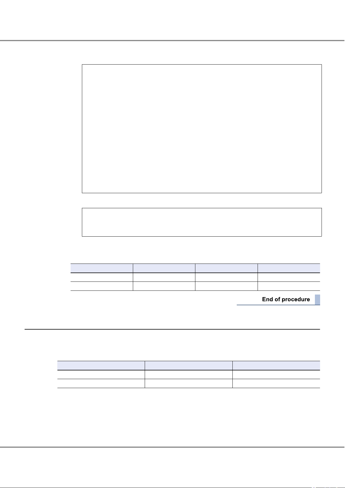
Chapter 3
3.3 Setting Up the Server
Setup Procedure for QLogic Fibre Channel Cards
(6) Enter "4" to select "4: Return to Previous Menu".
The Main Menu reappears.
Main Menu
1: Display System Information
2: Display HBA Settings
3: Display HBA Information
4: Display Device List
5: Display LUN List
6: Configure HBA Settings
7: Target Persistent Binding
8: Selective LUNs
9: Boot Device Settings
10: Driver Settings
11: HBA Utilities
12: Flash Beacon
13: Diagnostics
14: Statistics
15: Help
16: Quit
(7) Enter "16" to quit.
Enter choice => 0
#
4 Add the results in the "WWN instance management table for the server".
Example:
Physical slot name WWN Instance name Physical path name
21-00-00-E0-8B-91-D9-4F hba0 /pci@b,2000/QLGC,qla@2
21-01-00-E0-8B-91-D9-4F hba1 /pci@b,2000/QLGC,qla@2,1
3.3.2 Creating a WWN Instance Management Table for Storage System
Create a "WWN instance management table for storage system" that summarizes information relating to CA
in the ETERNUS DX/AF storage systems.
When there are two ports on the ETERNUS DX/AF storage systems:
Channel Adapter
CM0CA0Port0 202000e000cb0001 16
CM1CA0Port0 203000e000cb0001 16
WWN T_ID
Check the following items and enter them in the WWN instance management table for storage system.
Channel Adapter
•
CA name in the ETERNUS DX/AF storage systems
WWN
•
The WWN for each CA in the ETERNUS DX/AF (check using ETERNUS Web GUI or ETERNUSmgr)
60
FUJITSU Storage ETERNUS DX, ETERNUS AF Configuration Guide -Server Connection- (Fibre Channel) for Oracle Solaris
Copyright 2017 FUJITSU LIMITED
P3AM-6312-18ENZ0
Page 61
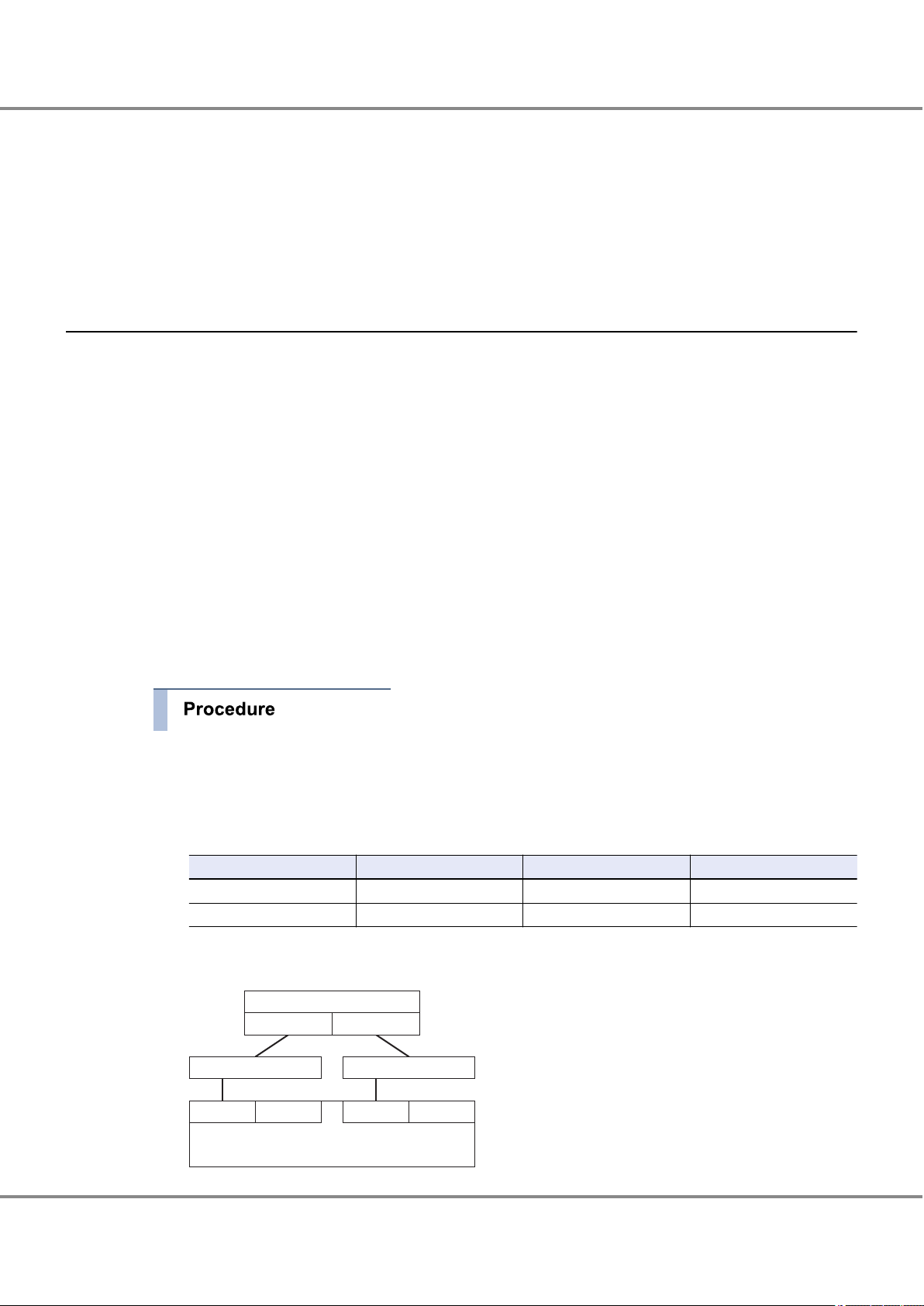
Server#0
Slot0
Slot1
CA0 Port0
CM0
CA0 Port1
ETERNUS DX/AF
Fibre Channel Switch A Fibre Channel Switch B
CM1
CA0 Port1 CA0 Port0
Chapter 3
3.3 Setting Up the Server
Setup Procedure for QLogic Fibre Channel Cards
T_ID
•
The SCSI target ID (decimal value) that is to be defined for each CA (check using ETERNUS Web GUI or ETERNUSmgr)
For switch connections, the SCSI target ID is irrelevant to the physical protocol, however it must be defined
as a Solaris OS SCSI driver setting. Values matched to the server environment and connection state of the
devices must be set beforehand.
It is recommended to set the same target ID to CAs that configures a multipath.
3.3.3 Creating a Target Binding Table
This procedure is not necessary for direct connections.
Target binding logically binds the Fibre Channel card installed in the server, and the CA on the ETERNUS
DX/AF storage systems to be connected to the server.
Target binding binds the instance name of the Fibre Channel card, channel adapter name, WWN, and target
ID.
Enter the required information for target binding in the "target binding table". Create "Target binding tables"
for each server to be connected.
Enter the following information in the target binding table.
Name of target server
•
Channel Adapter names and their SCSI target IDs
•
The "channel adapter names" and "target IDs" entered in the "WWN instance management table for storage system"
RAID-WWN
•
The WWN entered in the "WWN instance management table for storage system"
1 Enter the target information to be set for the server.
Reflect the information from the "WWN instance management table for storage system" in the "target
binding table".
Example:
Channel Adapter name WWN T_ID Instance name
CM0CA0Port0 202000e000cb0001 16
CM1CA0Port0 203000e000cb0001 16
2 Confirm the connection path(s) in the system.
Example:
FUJITSU Storage ETERNUS DX, ETERNUS AF Configuration Guide -Server Connection- (Fibre Channel) for Oracle Solaris
61
Copyright 2017 FUJITSU LIMITED
P3AM-6312-18ENZ0
Page 62

[WWN instance management table for the server]
[target binding table]
1. From the two tables,
find the same
combination of
physical slot name
and Channel
Adapter as listed in
the path route table.
SERV1_SLOT0
SERV1_SLOT1
10000000c9366046
10000000c9365d9e
lpfc0
lpfc1
Physical slot name
WWN
Instance name
16
16
CM0CA0Port0
CM1CA0Port0
202000c000cb0001
203000c000cb0001
Channel Adapter name SCSI T_ID RAID-WWN
Instance name
lpfc0
lpfc1
2. Record the
instance name
in the same row
as the physical
slot name in the
target binding table.
Chapter 3
3.3 Setting Up the Server
Setup Procedure for QLogic Fibre Channel Cards
Physical slots on Server#0 and CAs on the ETERNUS DX/AF storage systems are connected in the following paths.
• Server#0 SLOT0 - CM0CA0
• Server#0 SLOT1 - CM1CA0
3 Based on the connection path(s) confirmed in Step 2 and the information in the "WWN instance man-
agement table for the server", enter the instance names corresponding to the physical slot names on
the server into the "target binding table".
This completes the target binding table.
3.3.4 Setting the Configuration File
Edit the configuration file according to the "WWN instance management table for the server", "WWN instance
management table for storage system", and "target binding table". For how to set to the configuration file
and the setting example, refer to "3.5 Required Driver Parameters" (page 66).
Check the WWN instance management table for the server, WWN instance management table for storage
system, and target binding table for any omissions.
3.3.5 Re-checking the Settings
After the settings are complete, re-check the configuration file for any incorrect settings.
Check the target binding values before rebooting the server. If the server boots with a setting error, it may
recognize a different storage system from that set in the system configuration, without generating a connection error.
FUJITSU Storage ETERNUS DX, ETERNUS AF Configuration Guide -Server Connection- (Fibre Channel) for Oracle Solaris
Copyright 2017 FUJITSU LIMITED
62
P3AM-6312-18ENZ0
Page 63

Chapter 3
3.4 Setting Up the Server to Recognize the Logical Units
Setup Procedure for QLogic Fibre Channel Cards
3.4 Setting Up the Server to Recognize the Logical Units
3.4.1 Recognizing Logical Units with the sd Driver
Make the server recognize the ETERNUS DX/AF logical units using the sd driver.
First, confirm that the logical unit settings on the ETERNUS DX/AF storage systems are correct. Next, check
that Fibre Channel card IDs are described in the sd driver's configuration file (sd.conf).
Then reboot the server to get it to recognize the logical units.
3.4.1.1 Logical Unit Recognition
Make sure that the sd driver's configuration file (sd.conf) contains the following line using text editor such as
vi: name="sd" parent="qla2300" target=2048;
Add this line if it does not exist.
Solaris 11 OS
•
If the "/etc/driver/drv/sd.conf” file does not exist, copy the "/kernel/drv/sd.conf" file to the "/etc/driver/drv"
directory and add the line to the newly copied "sd.conf" file.
If the "/etc/driver/drv/sd.conf” file exists, do not copy over the file but instead add the line to the existing
"sd.conf" file.
Solaris 10 OS
•
Add the line to the "/kernel/drv/sd.conf" file.
63
FUJITSU Storage ETERNUS DX, ETERNUS AF Configuration Guide -Server Connection- (Fibre Channel) for Oracle Solaris
Copyright 2017 FUJITSU LIMITED
P3AM-6312-18ENZ0
Page 64

Chapter 3
3.4 Setting Up the Server to Recognize the Logical Units
Setup Procedure for QLogic Fibre Channel Cards
Example:
#
# Copyright 2006 Sun Microsystems, Inc. All rights reserved.
# Use is subject to license terms.
#
#ident "@(#)sd.conf 1.10 06/02/08 SMI"
name="sd" class="scsi" class_prop="atapi"
target=0 lun=0;
name="sd" class="scsi" class_prop="atapi"
target=1 lun=0;
name="sd" class="scsi" class_prop="atapi"
target=2 lun=0;
name="sd" class="scsi" class_prop="atapi"
target=3 lun=0;
name="sd" class="scsi"
target=4 lun=0;
:
:
name="sd" class="scsi"
target=15 lun=0;
#
# Enable Target 7 for the mpt SCSI/SAS/SATA driver. Target 7 has @
# traditionally been reserved for legacy SCSI HBAs, but SAS controllers
# supported by the mpt driver do not use target 7 for that purpose.
# Enabling Target 7 allows the use of 8 disks on those controllers.
#
name="sd" parent="mpt"
target=7 lun=0;
name="sd" parent="qla2300" target=2048;
Check the underlined portion.
64
FUJITSU Storage ETERNUS DX, ETERNUS AF Configuration Guide -Server Connection- (Fibre Channel) for Oracle Solaris
Copyright 2017 FUJITSU LIMITED
P3AM-6312-18ENZ0
Page 65

Chapter 3
3.4 Setting Up the Server to Recognize the Logical Units
Setup Procedure for QLogic Fibre Channel Cards
3.4.1.2 Getting the Server to Recognize the Logical Units
The server now needs to use the new sd driver settings to recognize the logical units.
1 Reconfigure and reboot the server to get it to recognize the listed logical units. Execute the following
command.
The ETERNUS DX/AF can be reconfigured by creating the "/reconfigure" file and rebooting the server.
# touch /reconfigure
# /usr/sbin/shutdown -y -g0 -i6
2 After the server has booted up, log in as a superuser, and use the "format" command to confirm that
the storage system and all the logical units have been correctly recognized.
# format
Example:
• Target ID=16, lun=0 and 1 of ETERNUS DX400 S2 series are connected to the physical path "/pci@b,
2000/QLGC,qla@2", and c4t16d0 and c4t16d1 are assigned to each of these LUNs.
• Target ID=16, lun=0 and 1 of ETERNUS DX400 S2 series are connected to the physical path "/pci@b,
2000/QLGC,qla@2,1", and c5t16d0 and c5t16d1 are assigned to each of these LUNs.
# format
Searching for disks...done
AVAILABLE DISK SELECTIONS:
0. c0t0d0 <SUN18G cyl 7506 alt 2 hd 19 sec 248>
/sbus@3,0/SUNW,fas@3,8800000/sd@0,0
1. c4t16d0 <FUJITSU-ETERNUS_DX400 cyl 260 alt 2 hd 64 sec 256>
/pci@b,2000/QLGC,qla@2/sd@0,0
2. c4t16d1 <FUJITSU-ETERNUS_DX400 cyl 260 alt 2 hd 64 sec 256>
/pci@b,2000/QLGC,qla@2/sd@0,1
3. c5t16d0 <FUJITSU-ETERNUS_DX400 cyl 260 alt 2 hd 64 sec 256>
/pci@b,2000/QLGC,qla@2,1/sd@0,0
4. c5t16d1 <FUJITSU-ETERNUS_DX400 cyl 260 alt 2 hd 64 sec 256>
/pci@b,2000/QLGC,qla@2,1/sd@0,1
3 Check that "sd@xx,x" has been displayed following the physical path name.
This message enables you to check that the logical units are recognized by the sd driver.
65
FUJITSU Storage ETERNUS DX, ETERNUS AF Configuration Guide -Server Connection- (Fibre Channel) for Oracle Solaris
Copyright 2017 FUJITSU LIMITED
P3AM-6312-18ENZ0
Page 66

Chapter 3 Setup Procedure for QLogic Fibre Channel Cards
3.5 Required Driver Parameters
3.5 Required Driver Parameters
3.5.1 Setting Up the Parameters
The parameters in the "/kernel/drv/qla2300.conf" configuration file need to be edited as described below.
Original configuration file must be backed up before editing.
Example:
cp /kernel/drv/qla2300.conf ./qla2300.conf.backup
Edit the configuration file according to the following parameter list.
3.5.1.1 qla2300.conf Parameter Values
These settings are common for all Solaris 10 OS, Solaris 9 OS, and Solaris 8 OS versions.
•
Proper instance names should be specified in place of the item names.
•
Check the "3.3.1 Creating a WWN Instance Management Table for the Server" (page 56) for the actual "X"
•
instance numbers to use in the "hbaX" below.
Parameter
hbaX-SCSI-target-id-<X>-fibre-channelport-name="<Storage WWPN>";
hbaX-max-frame-length 2048 2048 —
hbaX-execution-throttle Arbitrary (*2)
hbaX-login-retry-count 8 8 —
hbaX-enable-adapter-hard-loop-ID 1 0 1 for direct connection
hbaX-adapter-hard-loop-ID 125 0 For each direct connection
hbaX-enable-LIP-reset 0 0 —
hbaX-enable-LIP-full-login 0 0 Non-default value
hbaX-enable-target-reset 0 0 —
hbaX-reset-delay 5 5 —
hbaX-port-down-retry-count 8 8 —
hbaX-port-down-retry-delay 0 0 —
hbaX-maximum-luns-per-target 8 8 —
hbaX-connection-options 0 1
Setting value (for direct
connection)
(*1) (*1) —
(Up to 512 for each FC
port of the ETERNUS
DX/AF)
Setting value (for switch
connection)
Arbitrary (*2)
(Up to 512 for each FC
port of the ETERNUS
DX/AF)
Remarks
Non-default value
instance: assign in descending order, starting at
125
0 for direct connection
•
1 for switch connection
•
66
FUJITSU Storage ETERNUS DX, ETERNUS AF Configuration Guide -Server Connection- (Fibre Channel) for Oracle Solaris
Copyright 2017 FUJITSU LIMITED
P3AM-6312-18ENZ0
Page 67

Channel Adapter name
SCSI T-ID
Alias name (WWN)
Instance name
CM0CA0Port0
CM1CA0Port0
16
16
202000e000cb0001
203000e000cb0001
hba0
hba1
hba0-SCSI-target-id-16-fibre-channel-port-name="202000e000cb0001"
hba1-SCSI-target-id-16-fibre-channel-port-name="203000e000cb0001"
Chapter 3 Setup Procedure for QLogic Fibre Channel Cards
3.5 Required Driver Parameters
Parameter
Setting value (for direct
connection)
Setting value (for switch
connection)
Remarks
hbaX-fc-tape 0 0 Non-default value
hbaX-fc-data-rate 1, 3, 4, 5, or 6 0, 1, 3, 4, 5, or 6 (*3)
The following values may
be used:
0 g 1Gbit/s fixed
1 g 2Gbit/s fixed
2 g Auto (default)
3 g 4Gbit/s fixed
4 g 8Gbit/s fixed
5 g 16Gbit/s fixed
6 g 32Gbit/s fixed
hbaX-pci-latency-timer 0x40 0x40 —
hbaX-pci-x-max-memory-read-byte-
0 0 —
count
hbaX-link-down-error 1 1 —
hbaX-link-down-timeout 60 60 —
hbaX-persistent-binding-configuration 0 0 —
hbaX-persistent-binding-by-port-ID 0 0 —
hbaX-fast-error-reporting 0 0 —
hbaX-extended-logging 0 0 —
hbaX-queue-full-retry-count 16 16 Non-default value
hbaX-queue-full-retry-delay 2 2 —
hbaX-security-protocols 0 0 —
hbaX-FDMI-support 0 0 —
hbaX-VPD-support 0 0 —
hbaX-AIF-support 0 0 Non-default value
*1: Set as follows:
hbaX-SCSI-target-id-<X>-fibre-channel-port-name="<Storage WWPN>";
Check the target binding table for the Storage WWPN setting.
*2: Recommended value = 512 ¸ (number of Fibre Channel ports that are connected to a single CA port)
(Round the result down)
Use the value of "8" if the actual result is lower.
FUJITSU Storage ETERNUS DX, ETERNUS AF Configuration Guide -Server Connection- (Fibre Channel) for Oracle Solaris
Copyright 2017 FUJITSU LIMITED
67
P3AM-6312-18ENZ0
Page 68

Chapter 3 Setup Procedure for QLogic Fibre Channel Cards
3.5 Required Driver Parameters
*3: "hbaX-fc-data-rate" setting value
Fibre
Channel
card
transfer
rate
32Gbit/s 6 5 4 — — 6 5 4 —
16Gbit/s 5 5 4 3 — 5 5 4 3
8Gbit/s 4 4 4 3 1 4 4 4 3
4Gbit/s — 3 3 3 1 — 3 3 3
2Gbit/s — — 1 1 1 — — 1 1
Switch connection
Fibre Channel switch transfer rate
32Gbit/s 16Gbit/s 8Gbit/s 4Gbit/s 2Gbit/s 32Gbit/s 16Gbit/s 8Gbit/s 4Gbit/s
Direct connection
CA transfer rate
68
FUJITSU Storage ETERNUS DX, ETERNUS AF Configuration Guide -Server Connection- (Fibre Channel) for Oracle Solaris
Copyright 2017 FUJITSU LIMITED
P3AM-6312-18ENZ0
Page 69

# Copyright (C) QLogic Corporation 1996-2008. All rights reserved.
#
# File is setup as the default parameters for all adapters in the
# system.
# If a parameter needs to be changed for a particular adapter,
# make a copy of the parameter. Then change the hba number
# (decimal) in the parameter to match the adapter instance number
# that is displayed during the boot process. Now alter the
# parameter for the adapter.
#
# example:
# Setting loop down timeout for adapter instance 3 and 4
# respectively.
#
# Before:
# hba0-link-down-timeout=60;
#
# After:
# hba0-link-down-timeout=60;
# hba3-link-down-timeout=120;
# hba4-link-down-timeout=240;
#
#
# ===============================
# Target Persistent Name Binding
# ===============================
#
# Note: This persistent binding section only applies if the string
# "qla-mp-config-required" does NOT exist. This string refects
# the fact that the GUI or CLI utilities have made alternate
# persistent binding entries which override the manual persistent
# binding entries documented in this section.
#
# The Persistent Name Binding support for target devices associates a
# SCSI target ID to a specified device World Wide Port Name. In other
# words, this entry changes the target ID of the specified device
# to the number specified in the entry.
#
# To enable it, lines of the following format should be added
# in the qla2300.conf file:
#
# hba<#>-SCSI-target-id-<#>-fibre-channel-port-name="<device WWPN>";
hba0-SCSI-target-id-16-fibre-channel-port-name="2150000b5d6a0109";
hba1-SCSI-target-id-16-fibre-channel-port-name="2151000b5d6a0109";
#
# For example, to associate the following WWPN with target ID 2
# on adapter instance 1, the entry will be:
#
# hba1-SCSI-target-id-2-fibre-channel-port-name="2100002037004ac9";
#
# *******
# IMPORTANT
# *******
#
# - Unlike other parameter entries in the qla2300.conf file, values
# indicated in persistent name binding entries for instance 0 does
# not apply to other instances when there are no entries for the
# other instances.
# - Persistent Name Binding entries are optional entries in the
# qla2300.conf file. These entries do not dictate which devices
# are scanned by the driver, and do not perform any device masking,
# unless the "Persistent Binding Only Option" is set. Absence of
# this entry for any given device name or SCSI ID does not direct
# the driver to perform any type of device masking, unless the
# "Persistent Binding Only Option" is set.
#
# - For target devices, if no Persistent Name Binding entries are
# specified, the default SCSI target IDs assigned will be the loop
# ID of the devices, if failover is disabled else will start at 0.
# Please refer to the FAQ section for which default SCSI target IDs
# are assigned to fabric devices.
#
# ***********************
# CAUTION CAUTION CAUTION
# ***********************
#
For both direct connections and switch connections, add these settings.
Chapter 3 Setup Procedure for QLogic Fibre Channel Cards
3.5 Required Driver Parameters
3.5.1.2 /kernel/drv/qla2300.conf Example
The following example is for an ETERNUS DX8100/DX8400/DX8700 switch connection.
FUJITSU Storage ETERNUS DX, ETERNUS AF Configuration Guide -Server Connection- (Fibre Channel) for Oracle Solaris
Copyright 2017 FUJITSU LIMITED
69
P3AM-6312-18ENZ0
Page 70

# /kernel/drv/st.conf file, it is possible to purposely mask off
# certain devices of all adapter instances from the operating system,
# by purposely commenting out/deleting entries in the sd.conf/st.conf
# file for those SCSI target IDs/LUNs bound to all adapter instances.
# However, when the devices are shared among multiple adapters,
# doing so requires extreme caution, and it is strongly recommended
# that all target devices be bound with all adapter instances so that
# the devices will show up in a predeterminable way. A shared device
# which is bound on one adapter instance but unbound on another
# adapter instance may show up at a SCSI target ID which is
# unexpected by the user for the unbound adapter instance, which may
# lead to possible data corruption on the device if the user
# unknowingly writes to the unexpected device.
#
# The QLogic Solaris SCSI HBA driver does not filter out the OS
# scanning of SCSI devices, except when the "Persistent Binding
# Only Option" is set. The target IDs/LUNs scanned by the OS are
# based on the entries specified in the sd.conf and st.conf files.
# When the HBA driver first initializes during the system boot
# process, it assigns a target ID internally to all of the devices it
# detected. During the OS device scan, the driver ignores the 'class'
# value indicated in the sd.conf/st.conf file and processes the IOs
# addressed to a device whose target ID/LUN matches that of a device
# previously detected by the driver.
#
# Solaris x86 properties.
flow_control="duplx";
queue="qfifo";
disk="scdk";
tape="sctp";
#
# Solaris force attach all possible driver instances during system
# startup property.
#
ddi-forceattach=1;
# Maximum fibre channel frame size.
# Range: 512, 1024 or 2048 bytes
hba0-max-frame-length=2048;
hba1-max-frame-length=2048;
# Maximum number of commands queued on each logical unit.
# Range: 1 - 65535
hba0-execution-throttle=20;
hba1-execution-throttle=20;
# Number of port login retry attempts.
# Range: 0 - 255
hba0-login-retry-count=8;
hba1-login-retry-count=8;
# Enable/disable the use adapter hard loop ID address on the fibre
# channel bus.
# 0 = disable, 1 = enabled
hba0-enable-adapter-hard-loop-ID=0;
hba1-enable-adapter-hard-loop-ID=0;
# Adapter hard loop ID address to use on the fibre channel bus.
# Range: 0 - 125
hba0-adapter-hard-loop-ID=0;
hba1-adapter-hard-loop-ID=0;
# Enable/disable the use LIP reset for loop reset.
# 0 = disable, 1 = enabled
hba0-enable-LIP-reset=0;
hba1-enable-LIP-reset=0;
# Enable/disable the use LIP full login for loop reset.
# 0 = disable, 1 = enabled
hba0-enable-LIP-full-login=0;
hba1-enable-LIP-full-login=0;
# Enable/disable the use of target reset for loop reset.
# 0 = disable, 1 = enabled
hba0-enable-target-reset=0;
hba1-enable-target-reset=0;
# Amount of time to delay after a loop reset for starting any new
# I/O commands.
# Range: 0 - 255 seconds
hba0-reset-delay=5;
hba1-reset-delay=5;
# Number of times to retry a port that is not responding.
# Range: 0 - 255
For both direct connections and switch connections,
add these settings.
For direct connections, set the value for each
instance in descending order, starting from 125.
For direct connections, set to "1".
# When the Persistent Name Binding entries are used in combination
# with the device entries in the /kernel/drv/sd.conf or
For both direct connections and switch connections,
add these settings.
For both direct connections and switch connections,
add these settings.
For both direct connections and switch connections,
add these settings.
For both direct connections and switch connections,
add these settings.
For both direct connections and switch connections,
add these settings.
For both direct connections and switch connections,
add these settings.
Chapter 3 Setup Procedure for QLogic Fibre Channel Cards
3.5 Required Driver Parameters
FUJITSU Storage ETERNUS DX, ETERNUS AF Configuration Guide -Server Connection- (Fibre Channel) for Oracle Solaris
Copyright 2017 FUJITSU LIMITED
70
P3AM-6312-18ENZ0
Page 71

hba0-port-down-retry-count=8;
hba1-port-down-retry-count=8;
# Amount of time to delay between port down retries.
# Range: 0 - 255 seconds
hba0-port-down-retry-delay=0;
hba1-port-down-retry-delay=0;
# Maximum number of LUNs to scan for, if a device does not
# support SCSI Report LUNs command.
# Range: 1 - 256
hba0-maximum-luns-per-target=8;
hba1-maximum-luns-per-target=8;
# Connection options.
# 0 = loop only
# 1 = point-to-point only
# 2 = loop preferred, otherwise point-to-point
hba0-connection-options=1;
hba1-connection-options=1;
# Enable FCP 2 Error Recovery support enable/disable.
# 0 = disable, 1 = enabled
hba0-fc-tape=0;
hba1-fc-tape=0;
# Fibre Channel Data Rate Option.
# 0 = 1 gigabit/second
# 1 = 2 gigabit/second
# 2 = Auto-negotiate
# 3 = 4 gigabit/second
# 4 = 8 gigabit/second
hba0-fc-data-rate=4;
hba1-fc-data-rate=4;
# PCI latency timer.
# Range: 0x8 - 0xF8 -- must be a multiple of 8
hba0-pci-latency-timer=0x40;
hba1-pci-latency-timer=0x40;
# During link down conditions enable/disable the reporting of
# errors.
# 0 = disabled, 1 = enable
hba0-link-down-error=1;
hba1-link-down-error=1;
# Amount of time to wait for loop to come up after it has gone down
# before reporting I/O errors.
# Range: 0 - 240 seconds
hba0-link-down-timeout=60;
hba1-link-down-timeout=60;
# Persistent binding only option.
# 0 = Reports to OS discovery of binded and non-binded devices
# 1 = Reports to OS discovery of persistent binded devices only
# Note: This entry is ignored when qla-mpconfig parameter is found.
hba0-persistent-binding-configuration=0;
hba1-persistent-binding-configuration=0;
# Persistent binding by port ID.
# 0 = disabled, 1 = enable
hba0-persistent-binding-by-port-ID=0;
hba1-persistent-binding-by-port-ID=0;
# Fast error reporting to Solaris, enabled/disabled.
# 0 = disabled, 1 = enable
hba0-fast-error-reporting=0;
hba1-fast-error-reporting=0;
# Extended logging level.
# Range: 0 - 255, 0 = disabled
hba0-extended-logging=0;
hba1-extended-logging=0;
# Number of times to retry a SCSI queue full error.
# Range: 0 - 255
hba0-queue-full-retry-count=16;
hba1-queue-full-retry-count=16;
# Amount of time to delay after a SCSI queue full error before
# starting any new I/O commands.
# Range: 0 - 255 seconds
hba0-queue-full-retry-delay=2;
hba1-queue-full-retry-delay=2;
# Enable DH-CHAP security protocols.
# 0 = disabled, 1 = enable
hba0-security-protocols=0;
hba1-security-protocols=0;
# FDMI support.
# 0 = disabled, 1 = enable
hba0-FDMI-support=0;
hba1-FDMI-support=0;
# Use target/lun VPD data for failover configuration support.
# 0 = disabled, 1 = enable
For both direct connections and switch connections,
add these settings.
For both direct connections and switch connections,
add these settings.
For both direct connections and switch connections,
add these settings.
For direct connections, set to "0".
For both direct connections and switch connections,
add these settings.
Each value indicates the following meaning:
0 --> 1G fixed
1 --> 2G fixed
2 --> Auto (default)
3 --> 4G fixed
4 --> 8G fixed
For both direct connections and switch connections,
add these settings.
For both direct connections and switch connections, add these settings.
For both direct connections and switch connections,
add these settings.
For both direct connections and switch connections,
add these settings.
For both direct connections and switch
connections, add these settings.
For both direct connections and switch connections,
add these settings.
For both direct connections and switch connections,
add these settings.
For both direct connections and switch connections,
add these settings.
For both direct connections and switch
connections, add these settings.
For both direct connections and switch connections,
add these settings.
For both direct connections and switch connections,
add these settings.
For both direct connections and switch connections,
add these settings.
Chapter 3 Setup Procedure for QLogic Fibre Channel Cards
3.5 Required Driver Parameters
FUJITSU Storage ETERNUS DX, ETERNUS AF Configuration Guide -Server Connection- (Fibre Channel) for Oracle Solaris
Copyright 2017 FUJITSU LIMITED
71
P3AM-6312-18ENZ0
Page 72

hba0-VPD-support=0;
hba1-VPD-support=0;
# Advance Interrupt Framework (AIF) support.
# 0 = disable AIF
# 1 = disable MSI-X
# 2 = disable MSI
# 3 = disable MSI and MSI-X
# 4 = system default
hba0-AIF-support=0;
hba1-AIF-support=0;
#####################################################################
# WARNING: Beginning of Configuration Data stored by the QLogic #
# Applications. Consult documentation before editing #
# any data past this text. #
#####################################################################
For both direct connections and switch connections,
add these settings.
For both direct connections and switch connections,
add these settings.
# Use target/lun VPD data for failover configuration support.
# 0 = disabled, 1 = enable
Chapter 3 Setup Procedure for QLogic Fibre Channel Cards
3.5 Required Driver Parameters
FUJITSU Storage ETERNUS DX, ETERNUS AF Configuration Guide -Server Connection- (Fibre Channel) for Oracle Solaris
Copyright 2017 FUJITSU LIMITED
72
P3AM-6312-18ENZ0
Page 73

Chapter 4
Operations When Using Brocade Fibre Channel
Cards
This chapter describes the procedures for "Installing the Driver and Setting Up the Server" and "Recognizing
the Logical Units" required to establish a connection between a server with Brocade Fibre Channel cards and
an ETERNUS DX/AF.
4.1 Workflow
Workflow
Installing the Fibre Channel Card Driver
Install the driver. Download the proper driver from the Brocade web-site as required.
"4.2 Installing the Fibre Channel Card Driver" (page 74)
•
Used for driver installation
•
Driver (downloaded from the Brocade web-site)
-
Creating Various Management Tables
Enter the necessary information in the "WWN Instance Management Table for the Server", "WWN Instance Management Table for Storage System", and "Target Binding Table".
"4.3 Setting Up the Server" (page 74)
•
"Appendix A Various Management Table Templates" (page 82)
•
Editing the Configuration File
Set the driver parameters by editing the configuration file.
"4.3 Setting Up the Server" (page 74)
•
73
FUJITSU Storage ETERNUS DX, ETERNUS AF Configuration Guide -Server Connection- (Fibre Channel) for Oracle Solaris
Copyright 2017 FUJITSU LIMITED
P3AM-6312-18ENZ0
Page 74

Chapter 4
4.2 Installing the Fibre Channel Card Driver
Operations When Using Brocade Fibre Channel Cards
Setting Up the Server to Recognize the Logical Units (LUNs)
Set the server to recognize the ETERNUS DX/AF storage systems' logical units.
"4.4 Setting Up the Server to Recognize the Logical Units" (page 81)
•
After completing all the required procedures in this manual, proceed to "Setting the Multipaths" in
"Configuration Guide -Server Connection- (Fibre Channel) for Oracle Solaris".
4.2 Installing the Fibre Channel Card Driver
Install the Fibre Channel card driver.
Download and install the driver from the Brocade web-site.
Refer to the following Brocade web-site for instructions on how to install the driver.
http://www.brocade.com/
4.3 Setting Up the Server
The server setup will vary according to how the ETERNUS DX/AF storage systems and server are to be connected.
Only switch connections are supported.
The Fibre Channel card Instance name, target WWN, and target ID information are necessary. Check each
item and enter them in the table. Edit the configuration file according to those information and make settings. Refer to the following sections to set.
"4.3.1 Creating a WWN Instance Management Table for the Server" (page 75)
•
"4.3.2 Setting Up the Fibre Channel Cards" (page 77)
•
"4.3.3 Setting the Configuration File (/etc/system)" (page 80)
•
74
FUJITSU Storage ETERNUS DX, ETERNUS AF Configuration Guide -Server Connection- (Fibre Channel) for Oracle Solaris
Copyright 2017 FUJITSU LIMITED
P3AM-6312-18ENZ0
Page 75

Chapter 4 Operations When Using Brocade Fibre Channel Cards
4.3 Setting Up the Server
4.3.1 Creating a WWN Instance Management Table for the Server
Create a "WWN instance management table for the server" with information regarding the Fibre Channel
card.
Determine the following information for each Fibre Channel card installed in the server and enter it into a
copy of the "WWN instance management table for the server". (found in "Appendix A Various Management
Table Templates" (page 82)).
Physical slot name
•
WWN
•
Number of the target controller connected to the Fibre Channel card
•
Instance name
•
Physical path name
•
WWN Instance Management Table for the Server
Physical slot name WWN Controller number Instance name Physical path name
1 Check the instance names.
"bfa + instance number" is the format used to represent Fibre Channel card instance names.
The instance number that corresponds to the physical path in which the Fibre Channel card is installed
is stored in the "/etc/path_to_inst" file at Fibre Channel card driver installation. Extract the necessary
lines using the "grep" command.
# grep "bfa" /etc/path_to_inst
Example:
# grep "bfa" /etc/path_to_inst
"/pci@7c0/pci@0/pci@8/bfa@0" 0 "bfa"
/pci@7c0/pci@0/pci@8/bfa@0,1" 1 "bfa"
"
The underlined portion "/pci@7c0/pci@0/pci@8/bfa@0,1" indicates the physical path name, and "1" indicates the instance number.
2 Enter the results in "Instance name" and "Physical path name" columns of the "WWN instance manage-
ment table for the server".
Example:
Physical slot
name
bfa0 /pci@7c0/pci@0/pci@8/bfa@0
bfa1 /pci@7c0/pci@0/pci@8/bfa@0,1
WWN
Controller number
Instance name Physical path name
75
FUJITSU Storage ETERNUS DX, ETERNUS AF Configuration Guide -Server Connection- (Fibre Channel) for Oracle Solaris
Copyright 2017 FUJITSU LIMITED
P3AM-6312-18ENZ0
Page 76
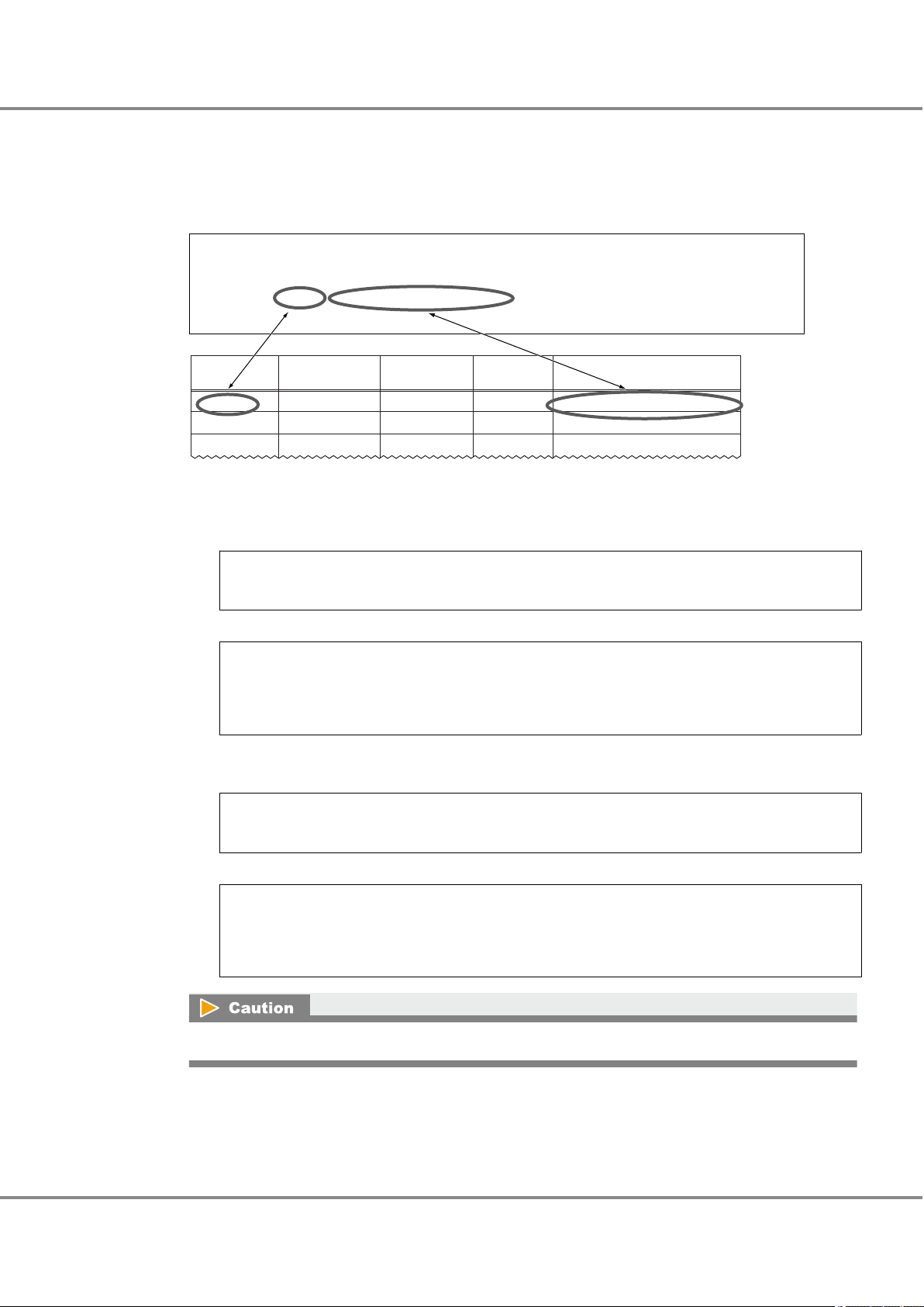
# /usr/platform/SUNW,SPARC-Enterprise-T2000/sbin/prtdiag -v
========================= IO Configuration ======================================
Location Type Slot Path Name Model
--------------------------------------------------------------------------------IOBD/PCIE1 PCIE 1 /pci@7c0/pci@0/pci@8/bfa@0 bfa-pciex1657,13 Brocade-8+
IOBD/PCIE2 PCIE 2 /pci@7c0/pci@0/pci@8/bfa@0,1 bfa-pciex1657,13 Brocade-8+
Physical slot
name
WWN
Instance
name
Physical path name
Controller
number
/pci@7c0/pci@0/pci@8/bfa@0bfa0PCIE1
/pci@7c0/pci@0/pci@8/bfa@0,1bfa1PCIE2
Chapter 4
4.3 Setting Up the Server
Operations When Using Brocade Fibre Channel Cards
3 Enter the slot number of the Fibre Channel card installed in the server in the "Physical slot name" field
of the "WWN instance management table for the server".
Use the "/usr/platform/`uname -i`/sbin/prtdiag -v" command to check the installed Fibre Channel card
slot number.
Example: Excerpt from "/usr/platform/SUNW,SPARC-Enterprise-T5220/sbin/prtdiag -v" output
Check the WWN of each Fibre Channel card.
4
(1) Use the following command to check the display order of the Fibre Channel card physical path
names.
# prtpicl -v -c scsi-fcp | grep devfs-path
Example:
# prtpicl -v -c scsi-fcp | grep devfs-path
:devfs-path /pci@7c0/pci@0/pci@8/bfa@0
:devfs-path /pci@7c0/pci@0/pci@8/bfa@0,1
(2) Use the following command to check the WWN of the Fibre Channel card that corresponds to the
physical path name. The result is displayed in the same order as shown in Step (1).
# prtpicl -v -c scsi-fcp | grep port-wwn
Example:
# prtpicl -v -c scsi-fcp | grep port-wwn
:bfa0-port-wwn 10:00:00:05:1e:e7:45:7b
:bfa1-port-wwn 10:00:00:05:1e:e7:45:7c
If the WWN does not appear in the procedure above, execute the "bcu port --list" command.
FUJITSU Storage ETERNUS DX, ETERNUS AF Configuration Guide -Server Connection- (Fibre Channel) for Oracle Solaris
76
Copyright 2017 FUJITSU LIMITED
P3AM-6312-18ENZ0
Page 77

Chapter 4
4.3 Setting Up the Server
Operations When Using Brocade Fibre Channel Cards
5 Add the results in the "WWN instance management table for the server".
Example:
Physical slot
name
PCIE1 100000051ee7457b bfa0 /pci@7c0/pci@0/pci@8/bfa@0
PCIE2 100000051ee7457c bfa1 /pci@7c0/pci@0/pci@8/bfa@0,1
WWN
Controller number
Instance name Physical path name
6 Check the controller number of the target connected to the Fibre Channel card.
Use the following command to check the controller number of the target connected to the Fibre Channel card. The controller number corresponds to the physical path displayed in Step (1).
# cfgadm -v
Example:
Ap_Id Receptacle Occupant Condition Information
When Type Busy phys_ID
c2 connected configured unknown
unavailable fc-fabric n /devices/pci@7c0/pci@0/pci@8/bfa@0/fp@0,0:fc
c3 connected configured unknown
unavailable fc-fabric n /devices/pci@7c0/pci@0/pci@8/bfa@0,1/fp@0,0:fc
7 Add the results in the "WWN instance management table for the server".
Example:
Physical slot
name
PCIE1 100000051ee7457b c2 bfa0 /pci@7c0/pci@0/pci@8/bfa@0
PCIE2 100000051ee7457c c3 bfa1 /pci@7c0/pci@0/pci@8/bfa@0,1
WWN
This completes the "WWN instance management table for the server".
4.3.2 Setting Up the Fibre Channel Cards
Brocade Command line Utility (BCU) is bundled with the Brocade Fibre Channel card driver.
Use the "bcu" command to check the port ID and to set the port speed, topology, and frame data size.
Port ID
•
Use the information obtained in "4.3.1 Creating a WWN Instance Management Table for the Server" (page
75) to check the port ID.
Port ID check command
bcu port --list
Controller number
Instance name Physical path name
77
FUJITSU Storage ETERNUS DX, ETERNUS AF Configuration Guide -Server Connection- (Fibre Channel) for Oracle Solaris
Copyright 2017 FUJITSU LIMITED
P3AM-6312-18ENZ0
Page 78
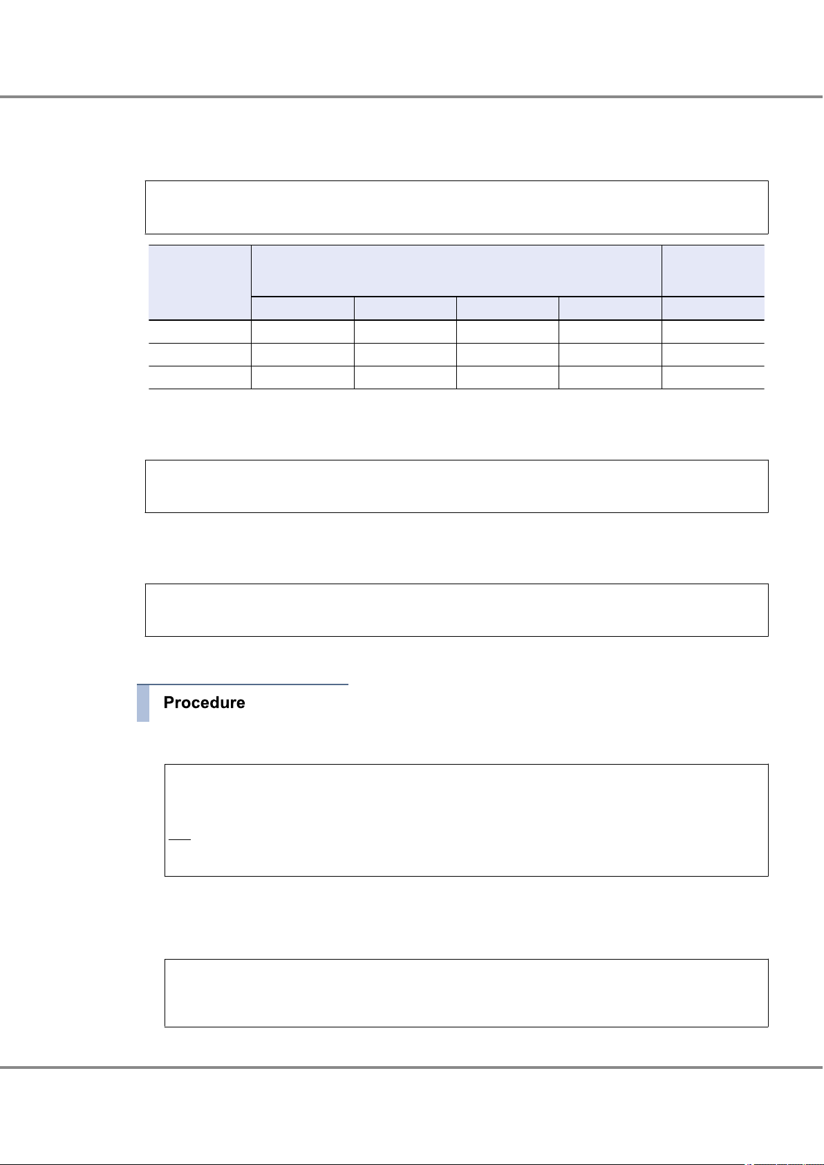
Chapter 4
4.3 Setting Up the Server
Operations When Using Brocade Fibre Channel Cards
Port speed
•
Specify the port speed value according to the table below.
"bcu" command format
bcu port --speed <port_id> [ 1|2|4|8|16|10|auto]
Fibre Channel
card transfer rate
16Gbit/s 16 8 4 — —
8Gbit/s 8 8 4 2 —
4Gbit/s 4 4 4 2 —
Topology
•
Set the topology value to "p2p".
"bcu" command format
Direct connection
Fibre Channel switch transfer rate
16Gbit/s 8Gbit/s 4Gbit/s 2Gbit/s 16Gbit/s CA
to Fibre Channel
cards
bcu port --topology <port_id> [auto | p2p]
Frame data size
•
Set the frame data size value to "2048".
"bcu" command format
bcu port --dfsize <port_id> [<dfsize>]
The following procedure shows an example for setting the port speed, topology, and frame data size.
1 Check the "port_id" of the target port.
# bcu port --list
Port# Type PWWN/MAC FC Addr/ Media State Spd
Eth dev
1/0 fc 10:00:00:05:1e:e7:45:7b 010400 sw Linkup 8G
1/1 fc 10:00:00:05:1e:e7:45:7c 010500 sw Linkup 8G
The underlined portion indicates the port ID.
The port ID checked here is used to set the port speed, topology, and frame data size.
2 Set the port speed to "8G".
# bcu port --speed 1/0 8
Setting will be enforced after port --disable and -enable
78
FUJITSU Storage ETERNUS DX, ETERNUS AF Configuration Guide -Server Connection- (Fibre Channel) for Oracle Solaris
Copyright 2017 FUJITSU LIMITED
P3AM-6312-18ENZ0
Page 79
Chapter 4
4.3 Setting Up the Server
Operations When Using Brocade Fibre Channel Cards
3 Set the topology to "p2p".
# bcu port --topology 1/0 p2p
Setting will be enforced after port --disable and --enable
4 Set the frame data size to "2048".
# bcu port --dfsize 1/0 2048
Setting will be enforced after port --disable and -enable
5 Execute the "port disable|enable" command to apply the port speed, topology, and frame data size set-
tings.
# bcu port --disable 1/0
port disabled
# bcu port --enable 1/0
port enabled
6 Check the port speed, topology, and frame data size that have been set.
• Port speed confirmation
# bcu port --speed 1/0
Current port speed is: 8G
Configured port speed is: 8G
• Topology confirmation
# bcu port --topology 1/0
Current topology is: P2P
Configured topology is: P2P
• Frame data size confirmation
# bcu port --dfsize 1/0
Port maximum receive data field size is 2048 -
To set multiple ports, repeat the above procedure for each port.
79
FUJITSU Storage ETERNUS DX, ETERNUS AF Configuration Guide -Server Connection- (Fibre Channel) for Oracle Solaris
Copyright 2017 FUJITSU LIMITED
P3AM-6312-18ENZ0
Page 80
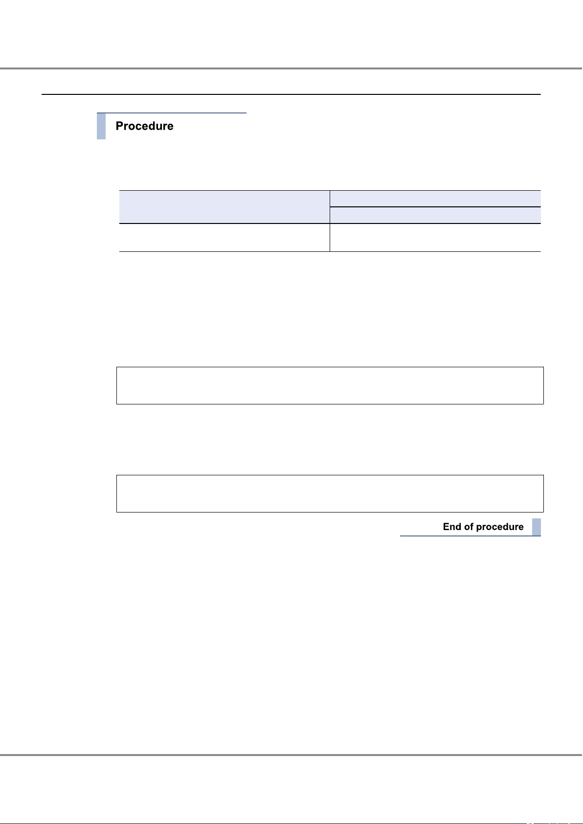
Chapter 4
4.3 Setting Up the Server
Operations When Using Brocade Fibre Channel Cards
4.3.3 Setting the Configuration File (/etc/system)
1 Edit the configuration file.
Edit the configuration file (/etc/system) and specify the command queue depth.
Model
ETERNUS DX/AF Arbitrary (*1)
Setting value
Command queue depth
(Up to 512 for each FC port of the ETERNUS DX/AF)
*1: Recommended value = 512 ¸ (number of Fibre Channel ports that are connected to a single CA
port) ¸ number of LUNs
(Round the result down)
Use the value of "8" if the actual result is lower.
Specify the command queue depth for the "ssd_max_throttle" parameter.
Add the "ssd_max_throttle" parameter if it does not exist.
Example:
set ssd:ssd_max_throttle = 20
2 After editing the configuration file, save it.
3 After the setting is complete, check the configuration file for incorrect settings.
4 Reboot the server.
# /usr/sbin/shutdown -y -g0 -i6
80
FUJITSU Storage ETERNUS DX, ETERNUS AF Configuration Guide -Server Connection- (Fibre Channel) for Oracle Solaris
Copyright 2017 FUJITSU LIMITED
P3AM-6312-18ENZ0
Page 81

Chapter 4
4.4 Setting Up the Server to Recognize the Logical Units
Operations When Using Brocade Fibre Channel Cards
4.4 Setting Up the Server to Recognize the Logical Units
Set the server to recognize the ETERNUS DX/AF storage systems' logical units.
Execute the following commands to check the path of the ETERNUS DX/AF to be connected.
1 Execute the following command to confirm that the server can access the logical units.
# cfgadm -al
# cfgadm -al
Ap_Id Type Receptacle Occupant Condition
c2 fc-fabric connected configured unknown
c2::500000e0d0400006 disk connected configured unknown
c3 fc-fabric connected configured unknown
c3::500000e0d0400086 disk connected configured unknown
Underlined portion indicates that the ETERNUS DX/AF CA (WWN:500000e0d0400086) are connected to
the Fibre Channel card port with controller number "c3".
2 Use the following command to confirm that the storage system and all the logical units have been cor-
rectly recognized.
# format
# format
Searching for disks...done
AVAILABLE DISK SELECTIONS:
0. c0t0d0 <SUN146G cyl 14087 alt 2 hd 24 sec 848>
/pci@780/pci@0/pci@9/scsi@0/sd@0,0
1. c2t500000E0D0400006d0 <FUJITSU-ETERNUS_DXL-0000 cyl 379 alt 2 hd 64 sec 256>
/pci@7c0/pci@0/pci@8/bfa@0/fp@0,0/ssd@w500000e0d0400006,0
2. c2t500000E0D0400006d1 <FUJITSU-ETERNUS_DXL-0000 cyl 379 alt 2 hd 64 sec 256>
/pci@7c0/pci@0/pci@8/bfa@0/fp@0,0/ssd@w500000e0d0400006,1
c3t500000E0D0400086d0 <FUJITSU-ETERNUS_DXL-0000 cyl 379 alt 2 hd 64 sec 256>
3.
/pci@7c0/pci@0/pci@8/bfa@0,1/fp@0,0/ssd@w500000e0d0400086,0
c3t500000E0D0400086d1 <FUJITSU-ETERNUS_DXL-0000 cyl 379 alt 2 hd 64 sec 256>
4.
/pci@7c0/pci@0/pci@8/bfa@0,1/fp@0,0/ssd@w500000e0d0400086,1
The underlined portion indicates that the ETERNUS DX/AF target ID=500000E0D0400086, lun=0 and 1
are connected to physical path /pci@7c0/pci@0/pci@8/bfa@0,1 and c3t500000E0D0400086d0 and
c3t500000E0D0400086d1 are assigned to each of these LUNs.
81
FUJITSU Storage ETERNUS DX, ETERNUS AF Configuration Guide -Server Connection- (Fibre Channel) for Oracle Solaris
Copyright 2017 FUJITSU LIMITED
P3AM-6312-18ENZ0
Page 82

Appendix A
Various Management Table Templates
The following management table templates are required for installation of Fibre Channel cards.
Use them as required.
A.1 WWN Instance Management Table for the Server
WWN instance management table for the server
Physical slot name WWN Controller number Instance name Physical path name
A.2 WWN Instance Management Table for Storage System
WWN instance management table for storage system
Channel Adapter WWN T_ID
82
FUJITSU Storage ETERNUS DX, ETERNUS AF Configuration Guide -Server Connection- (Fibre Channel) for Oracle Solaris
Copyright 2017 FUJITSU LIMITED
P3AM-6312-18ENZ0
Page 83

Appendix A Various Management Table Templates
A.3 Target Binding Table
A.3 Target Binding Table
Target binding table
Server name:
Channel Adapter name SCSI T_ID RAID-WWN Instance name Controller number
83
FUJITSU Storage ETERNUS DX, ETERNUS AF Configuration Guide -Server Connection- (Fibre Channel) for Oracle Solaris
Copyright 2017 FUJITSU LIMITED
P3AM-6312-18ENZ0
Page 84

FUJITSU Storage ETERNUS DX, ETERNUS AF Configuration Guide -Server Connection-
(Fibre Channel) for Oracle Solaris
Driver Settings for Non-Fujitsu Fibre Channel Cards
P3AM-6312-18ENZ0
Date of issuance: December 2017
Issuance responsibility: FUJITSU LIMITED
The content of this manual is subject to change without notice.
•
This manual was prepared with the utmost attention to detail. However, Fujitsu shall assume no responsibility for any
•
operational problems as the result of errors, omissions, or the use of information in this manual.
Fujitsu assumes no liability for damages to third party copyrights or other rights arising from the use of any information
•
in this manual.
The content of this manual may not be reproduced or distributed in part or in its entirety without prior permission from
•
Fujitsu.
Page 85

 Loading...