

Page 1

Operating Manual
Professional PC
ESPRIMO Q5xx / Q9xx
Page 2

Congratulations, you have
innovative Fujitsu product.
decided to buy an
The latest information about our products, useful tips, updates etc. is available
on our website: "
For automatic driver updates, go to:"http://support.ts.fujitsu.com/com/support/index.html"
Should you have any technical questions, please contact:
• our Hotline/Service Desk (see the Service Desk list or visit:
"
http://ts.fujitsu.com/support/servicedesk.html")
• Your sales partner
• Your sales office
We hope you really enjoy using your new Fujitsu system.
http://ts.fujitsu.com"
Page 3

Page 4

Copyright
Fujitsu Tec
Published by
Fujitsu Technology Solutions GmbH
Mies-van80807 Munich, Germany
Contact
h
All rights reserved, including intellectual property rights. Technical data subject to modifications and delivery subject to
availability. Any liability that the data a nd illustrations are complete, actual or correct is excluded. Designations may be
tradem
infringe the rights of such owner. You will find more informa tion at "
Order N
hnology Solutions 03/12
der-Rohe-Straße 8
s.fujitsu.com/support
ttp://t
arks and/or copyrights of the respective manufacturer, the use of which by third parties for their own purposes may
http://ts.fujitsu.com/term s_of_use.html"
o. Fujitsu Technology Solutions GmbH: A26361-K1011-Z321-1-7619, ed ition 1
Page 5

ESPRIMO Q5xx / Q9xx
Operating Manual
Your ESPRIMO 5
Ports and operating elements 7
Important notes 9
Getting started 13
Operation 26
Troubleshooting and tips 39
System expansions 43
Technical data 54
Index 55
Page 6

ESPRIMO is a registered trademark of Fujitsu Technology Solutions GmbH.
Windows 7, Windows Vista and Windows XP are registered trademarks of M icrosoft Corporation.
PS/2 is a registered trademark of International Business Machines, Inc.
Pentium is a registered trademark of I ntel Corporation, USA.
Kensington and MicroSaver are registered trademarks of ACCO World Corporation.
All other trademarks referenced are trademarks or registe red trademarks of their
respective owners, whose protected rights are acknowledged.
Copyright © Fujitsu Technology Solutions GmbH 2012
All rights reserved, including rights of translation, reproduction by printing, copying
or similar m e thods, either in part or in whole.
Noncompliance is subject to compensation for damages.
All r ights reserved, including rights created by p atent grant or registration of a utility model o r design.
Subject to availability and technical modifications.
Page 7

Contents
Contents
YourESPRIMO ......................................................................... 5
Notational conventions .................................................................. 6
Ports and operating elemen
Front ................................................................................... 7
Rear ................................................................................... 8
Importantnotes ........................................................................ 9
Safety information ....................................................................... 9
Transporting thedevice .................................................................. 9
Cleaning the device ..................................................................... 10
Energy saving,disposal and recycling .................................................... 10
CE marking ............................................................................ 11
FCC ComplianceStatement ............................................................. 12
FCC Class BComplianceStatement .................................................. 12
Getting started ......................................................................... 13
Unpacking and che
Steps for initial
Remove the protec
Installing the l
Setting up the de
Mounting the de
Connecting th
Connecting ex
Connecting th
Disconnecti
Ports on the d
Connecting a
Connecting
Connecting
Connectin
Switching
Operation .............................................................................. 26
Switch thedeviceon .................................................................... 26
Switchingoff the device ................................................................. 26
Indicators on the device ................................................................. 27
Keyboard ............................................................................... 28
Memory card reader . . . .................................................................. 30
Removing the memorycard .............................................................. 31
Optical drive (optional) .................................................................. 32
Wireless LAN / BlueTooth radio compo nents (device-dependent) . . . ......................... 34
SettingsinBIOS Setup Utility ............................................................ 34
on for the firsttime: installing thesoftware .......................................
Switch on
ng thesoftware ...............................................................
Installi
Important keys and keyboard shortcuts . . . . ............................................ 29
Inserting thememorycard ........................................................... 31
Handlingdata carriers ............................................................... 32
Inserting or removing adata carrier (slot) .............................................. 33
Switching the wireless components on and off . ........................................ 34
Startingthe BIOS Setup Utility ........................................................ 35
ckingthe delivery .....................................................
setup ....................................................................
tive film ...............................................................
owercover ................................................................
vice ....................................................................
viceonthe VESA interface ofa monitor ................................
epowercable .............................................................
ternal devices .............................................................
ecables ...............................................................
ng thecables ............................................................
evice ..................................................................
monitor ................................................................
aUSB mouse ............................................................
a USB keyboard . . .......................................................
gexternal devices tothe USBports .........................................
the monitor andthe machine ...............................................
ts .........................................................
13
13
13
14
16
18
20
21
21
21
22
22
23
23
23
24
24
25
7
Fujitsu Technology Solutions 3
Page 8

Contents
OperatingBIOS Setup Utility ......................................................... 35
Exiting BIOS Setup Utility ............................................................ 35
Propertyand dataprotection ............................................................. 36
Usingthe Security Lock .............................................................. 37
BIOS Setupsecurity functions ........................................................ 38
Troubleshooting and tips .............................................................. 39
Helpifproblems occur ................................................................... 39
Troubleshooting . . ....................................................................... 39
Power-on indicatorremains unlit afteryou have switched on your device ................. 39
The device cannot be switched off with the ON/O FF switch. . . .......................... 40
Monitor remains blank ............................................................... 40
No mouse pointer displayed onthe screen ............................................ 41
Time and/or date is not correct . . . . . . ................................................. 42
Errormessages onthe screen ........................................................ 42
Installing newsoftware .................................................................. 42
Restoringthe hard disk contents ......................................................... 42
Tips .................................................................................... 42
System expansions .................................................................... 43
Information about boards ................................................................ 44
Prepare to remove components . . ........................................................ 45
Opening the casing . . ................................................................... 45
Remove thelowercover ................................................................. 46
Open the service cover .................................................................. 47
Removing and installingthe hard disk .................................................... 48
Removing ahard disk ............................................................... 48
Installing ahard disk ................................................................. 49
Installing andremoving memoryexpansion ................................................ 50
Removing memory modules . . ........................................................ 51
Installing amemory module .......................................................... 51
Closethe service cover .................................................................. 52
Closing the casing ...................................................................... 52
Finish component removal . . . ............................................................ 53
Technicaldata ......................................................................... 54
Index .................................................................................. 55
4 Fujitsu Technology Solutions
Page 9

Your ESPRIMO
Your ESPRIMO
Overview
... is available with various configuration levels which differ in terms of
hardware and software equipment.
This manual tells you how to start using your device a nd how to operate it in daily use.
This manual applies for all configuration levels. Depen ding on the chosen configuration
level, some of the hardware components described may not be available on your PC.
Please also read the notes about your operating system.
Depending on the c onfiguration selected, the operating system is preinstalled
on your hard disk (e.g. Windows 7).
Further information on this device is provided:
• in the poster "Getting Started"
• in the "Safety/regul
• in the "Warranty" manual
• in the operating ma
• in the manual for the mainboard
• in your operating
• in the information files (e.g. *.PDF, *.HTML, *.DOC, *.CHM, *.TXT, *.HLP)
Some of the manuals listed can be found in electronic form on the "Drivers & Utilities" DVD.
You can access and view the required information using the Acrobat Reader
program, which is also included on the DVD. You can of course also
print out a copy of the manual if you prefer.
ations" manual
nual for the monitor
system documentation
Fujitsu Technology Solutions 5
Page 10
Your ESPRIMO
Notational conventions
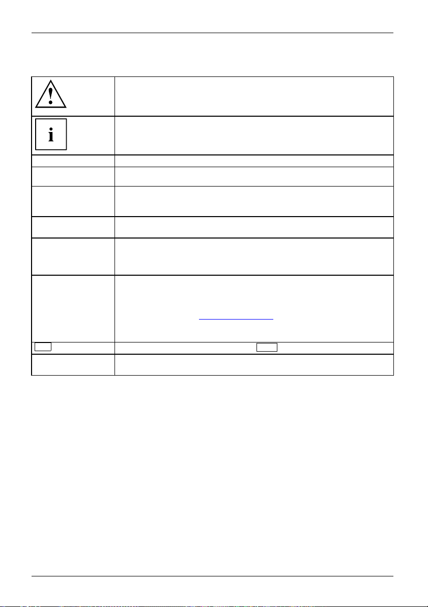
Pay particular attention to text marked with this symbol. Failure to observe
these warnings could pose a risk to health, damage the device or lead
to loss of data. The warranty will be invalidated if the device becomes
defective through failure to observe these warnings.
Indicates important informa
tion for the proper use of the device.
►
This font
This font
This font
"This font"
Key
This font
Indicates an activity that must be performed
Indicates a result
indicates data entered
the command line, e.g.
start a program (star
indicates information that is displayed on the screen by a program, e.g.:
Installation is complete.
indicates
• terms and texts used in a software interface, e.g.: Click on Save
• names of programs or files, e.g. Windows or setup.exe.
indicates
• cross-references to another section, e.g. "Safety information"
• cross-references to an external source, e.g. a web address: F or more
information, go to "
• Names of CDs, DVDs and titles or designations for other materials,
e.g.: "CD/DVD Drivers & Utilities" or "Safety/Regulations" manual
indicates a key on the keyboard, e.g:
indicates terms and texts that are emphasised or highlighted, e.g.: Do
not switch off the device
using the keyboard in a program dialogue or at
your password (Name123) or a command used to
t.exe)
http://ts.fujitsu.com"
F10
6 Fujitsu Technology Solutions
Page 11
Ports and operating elements
Ports and operating elements
Ports
This chapt er presents the individual hardware components of your device. This will provide
you w ith an overview of the ports and operating elements on the device. Please familiarise
yourself with these components before starting to work with your device.
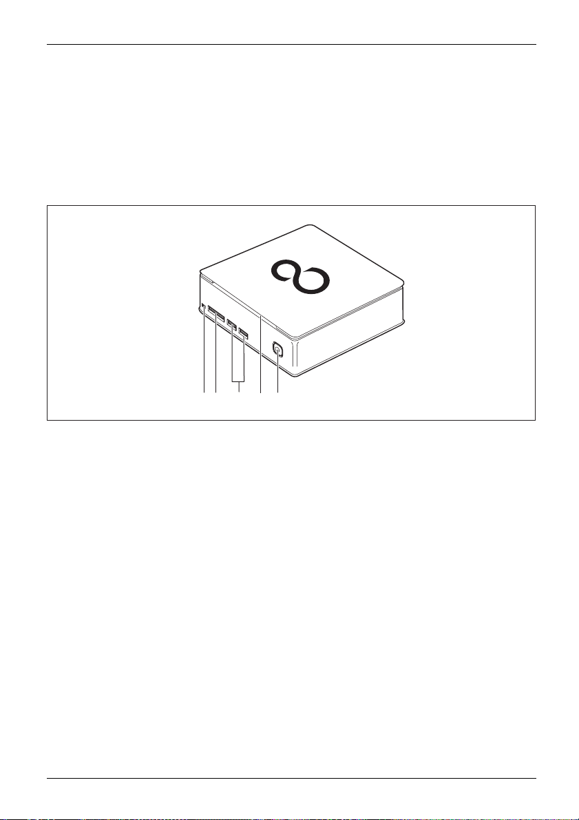
Front
5231
4
1 = Optical drive eject button
2 = Storage card reader
3=USBports
Fujitsu Technology Solutions 7
4 = Optical drive (optional)
5 = ON/OFF switch with power-on indicator
Page 12
Ports and operating elements
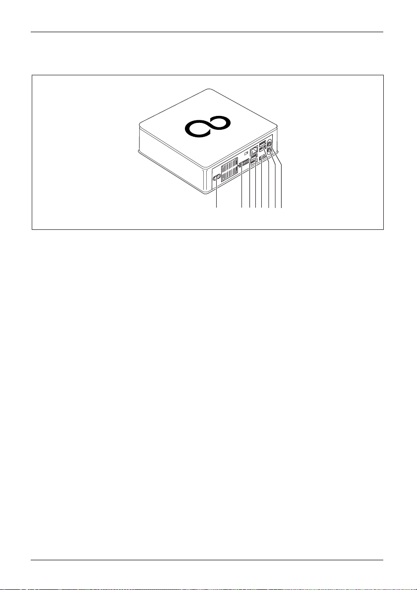
Rear
321
5
4
6
7
8
1 = Power connection (AC IN)
2=DVI-Iport
3 = LAN port
4 = USB ports
5 = DisplayPort / HDMI port
(device-dependent)
6 = USB ports
7 = Audio outpu t
8 = Microphone jack
8 Fujitsu Technology Solutions
Page 13
Important notes
ImportantnotesNotes
In this chapter you will find information regarding safety which it is essential to
take note of when working with your device.
Safety information
SafetyinformationNote
Please note the informat
and in the following safe
When installing and ope
environmental conditi
the instructions in Cha
When setting up the dev
thecasingreceives
cover the ventilati
You must only opera
device is set to the
You must remove the
mains voltage is c
Caution, compone
The activities
performed with
Repairs to the
Incorrect rep
to the equipme
described in these instructions must always be
the greatest care.
device must only be performed by qualified technicians.
airs could put the user at great risk or cause serious damage
nt (electric shock, risk of fire).
ion provided in the "Safety/regulations" manual
ty notes.
rating the device, please observe the notes on
ons in Ch apter "
pter "
Getting started", Page 13.
Technical data", Page 54 as well as
ice, make sure there is clearance all around it so that
enough ventilation. In order to avoid overheating, do not
on areas of the monitor or the device.
te the device if the rated voltage used by the
local mains voltage.
power plug from the power socket so that the
ompletely disconnected.
nts in the system can get very hot.
Important notes
Transportin
ation
rtation
Device,Transport
Retranspo
Transport all parts separately in their original packaging or in a packaging which
g the device
protects them from kno cks and jolts, to the new site.
Do not unpack them until all transportation manoeuvres are completed.
If the device is brought from a cold environment into the room where it will be
used, condensation may occur. To avoid damaging the device, w ait until it has
reached room temperature and is absolutely dry before initial startup.
Fujitsu Technology Solutions 9
Page 14

Important notes
Cleaning the device
Device,TransportationRetransportationSystemunit, seeDevice
Turn off all power and equipment switches and disconnect the power
plug from the mains outlet.
Do not clean any interior parts yourself, leave this job to a service technician.
Do not use any cleaning agents that contain abrasives or may corrode
plastic (alcohol, thinner or acetone).
Never clean the device with water! Water entering into the device could
present a serious risk to users (e.g. electric shock).
Ensure that no liquid enters the system.
The surface can be clea
moistened in mild dome
Use disinfectant wi
ned with a dry cloth. If particularly dirty, use a cloth that has been
stic detergent and then carefully wrung out.
pes to clean the keyboard and the mouse.
Energy saving, disposal and recycling
DisposalEnergysavingRecyclingDrivers&UtilitiesDVDUserDocumentationDVD
Further information can be found on the "Drivers & Utilities" DVD.
10 Fujitsu Technology Solutions
Page 15

CE marking
CEmarkingCEmarkingNotesElectromagneticcompatibilityLowvoltagedirective
Important notes
The shipped version of this device complies with the requirements
of European Union directives 2004/108/EC "Elektromagnetische
Verträglichkeit", 2006/95/EC "Niederspannungsrichtlinie" and 2009/125/EC
"Ökodesign Richtlinie".
CE marking for devices with radio component
This equ ipment complies with the requirements of Directive 1999/5/EC of the
European Parliament and Commission from 9 March, 1999 governing Radio
and Telecommunications Equipment and mutual recognition of conformity.
This equipment can be used in the following countries:
Belgium Bulgaria Denmark
Estonia Finland France
Germany
Greece
UK Ireland Iceland Italy
Latvia Liechtenstein Lithuania Luxembourg
Malta Netherlands Norway Austria
Poland Portugal Rumania
Sweden
Switzerland Slovakia Slovenia Spain
Czech Republic
Hungary
Cyprus
Contact the corresponding government office in the respective country for
current information on possible operating restrictions. If your country is
not included in the list, then please contact the corresponding supervisory
authority as to whether the use of this product is permitted in your country.
Fujitsu Technology Solutions 11
Page 16

Important notes
FCC Compliance Statement
If the device complies with the FCC regulations, the FCC sign can be found on the type rating plate.
FCC Class B Compliance State
The following statement applies to the products covered in this manual, unless otherwise specified
herein. T he statement for other products will appear in the accompanying documentation.
NOTE:
This equipment has been tested and found to comply with the limits for a "Class B" digital
device, pursuant to Part 15 of the FCC rules and meets all requirements of the Canadian
Interference-Causing Equipment Standard ICES-003 for digital apparatus. These limits are
designed to provide reasonable protection against harmful interference in a residential installation.
This equipment generates, uses and can radiate radio frequency energy and, if not installed
and used in strict accordance with the instructions, may cause harmful interference to radio
communications. However, there is no guarantee that interference will not occur in a particular
installation. If this equipment does cause harmful interference to radio or television reception ,
which can be determined by turning the equipment off and on, the user is encouraged to
try to correct the interference by one or more of the following measures:
• Reorient or relocate the receiving antenna.
• Increase the sep
• Connect the equipment into an outlet on a circuit different from that to
which the receiver is connected.
• Consult the de
Fujitsu Technology Solutions GmbH is not responsible for any radio or television interference
caused by unauthorized modifications of this equipment or the substitution or attachment
of connecting cables and equipment other than those specified by Fujitsu Technology
Solutions Gm bH. The correction of interferences caused by such unauthorized modification,
substitution or attachment will be the responsibility of the user.
The use of shielded I/O cables is required when connecting this equipment to any and all optional
peripheral or host devices. Failure to do so may violate FCC and ICES rules.
aration between equipment and the receiver.
aler or an experienced radio/TV technician for help.
ment
12 Fujitsu Technology Solutions
Page 17
Getting started
Getting started
Gettingstarted
Unpacking and checking the delivery
It is recommended not to throw away the original packaging material! It may be
required for reshipment at some later date.
PackagingCont entsofdeliveryPackaging,
► Unpack all the individual parts.
► Check the contents of the package for any visible damage caused during transport.
► Check whether the delivery conforms to the details in the delivery note.
► Should you discover that the delivery does not correspond to the delivery
Steps for initial setup
Preparingforfirstuse,overvie wPreparingforuse,
Only a few steps are necessary to put your new device into operation for the first time:
• Select a location for device and set up device
• Connect external devices such as mouse, keyboard and monitor
• Check the voltage at the mains outlet and connect th e device to an electrical outlet
• Switch the device on
You will learn more about the individual steps in the following sections.
Please observe the safety information in the "Important notes", Page 9 chapter.
note, notify your local sales outlet immediately.
External devices
If you have received other external devices in addition to your own device (e.g.
a printer), do not connect these until after the initial installation. The following
sections describe how to connect these external devices.
Drives and boards
If you have received drives or boards with your device, please do not install
them until after first-time setup. How to install drives and boards is de scribed
System expansions", Page 43 chapter.
in the "
Remove the protective film
p and underside and the lower cover are provided with protective film.
The to
► Remo
Fujitsu Technology Solutions 13
ve the p rotec tive film before initial startup.
Page 18
Getting started
Installing the lower cover
2
1
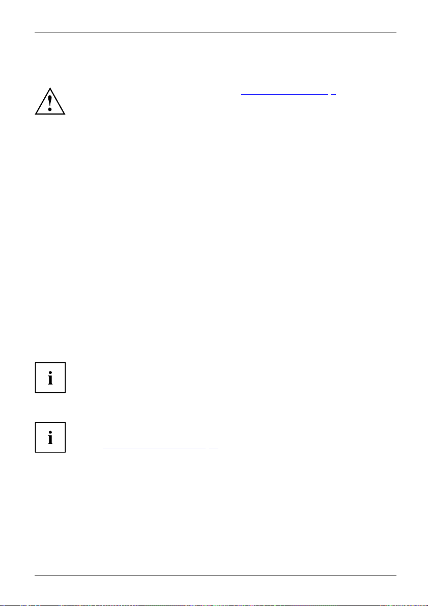
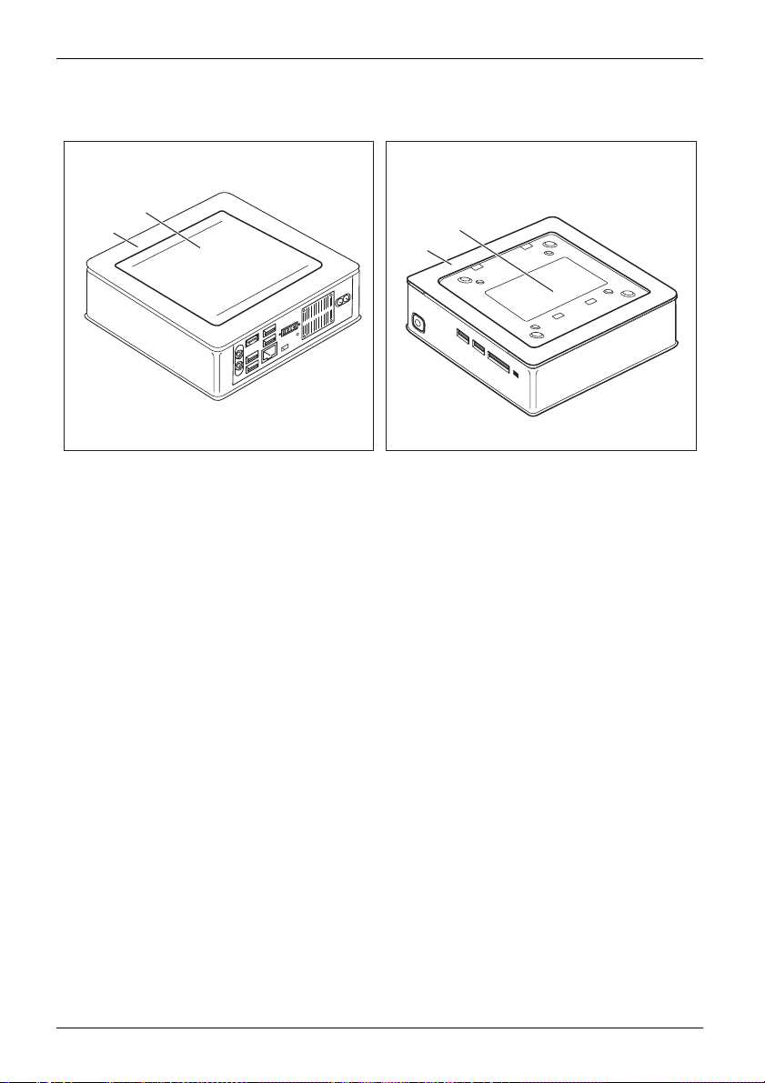
Device with device
cover (2)
The device is equipped with a device cover (1) on the underside. The device cover is divided
into two: during operation, the lower cover (2) is inserted in the device cover.
When your device is delivered, the l ower cover (2) is not yet installed on the underside
of the device, instead it is enclosed with the system, so that you can see the type rating
plate (3) and the software licence information during the initial start-up.
The type rating plate and the software licence are affixed on the device cover and are
normally not visible underneath the installed lower cover.
To install the lower cover before the initial start-up and to be able to use the
device for the first time, proceed as follows:
► Turn the device over and place it on a stable, flat and clean surface. If necessary, lay an
anti-slip cloth on this surface to prevent the device from being scratched.
cover (1), with installed lower
Device with device
plate (3), without
3
1
cover (1) and visible type
lower cover.
14 Fujitsu Technology Solutions
Page 19

Getting started
1
2
1
1
► Place the lower cover on the underside of the device as shown.
► Hook the lower cove
► Fold the cover in the direction of the arrow (2), until you feel and hear it engage.
You will find infor
r into the openings provided for it on the underside (1).
mation on removing the lower cover in section "
Remove the lower cover", Page 46.
Fujitsu Technology Solutions 15
Page 20

Getting started
Setting up the device
WorkstationErgonomicDevice
When installing your device, please read the recommendations and safety
notes in the "Safety/regulations" manual.
We recommend that you place your device on a surface which is not slippery. In
view of the many different finishes and varnishes used on furniture, it is possible
that the rubber feet will mark the surface they stand on.
Depending on the location of your device, troublesome vibrations and noises
may occur. To prevent this, a distance of at least 10 mm should be maintained
from other devices on casing sides without ventilation surfaces.
In order to avoid overheating, do not cover the ventilation areas
of the monitor or the device.
A minimum distance of 200 mm from the device must be observed for ventilation areas.
Do not stack several devices on one another and do not stand a monitor on the device.
Do not expose the device to extreme ambient conditions (see "
section "Ambient conditions"). Protect the device against dust, humidity and heat.
Technical data", Page 54,
Operating positi
on
You can use the dev
•horizontal:
ice in various operating positions:
16 Fujitsu Technology Solutions
Page 21

• vertical, on/off switch upwards:
• On the VESA interface of a monitor, on/off switch at the side:
Getting started
Fujitsu Technology Solutions 17
Page 22

Getting started
Mounting the device on the V ESA interface of a monitor
The device must be mounted on the monitor in such a way that the conne ctions
and operating controls can be accessed at the side.
► Remove the casing cover and the lower cover (see "
Page 45 and "Re move the lower cover", Page 46).
1
a
► Install the casing cover (a) on the rear of the monitor using the screws supplied (1).
1
1
1
Opening the casing",
18 Fujitsu Technology Solutions
Page 23

1
► Secure the device on the casing cover (1) mounted on the monitor.
Getting started
Fujitsu Technology Solutions 19
Page 24

Getting started
Connecting the power cable
PreparingforoperationPowercable
► Connect the power cable (1) to the power connection (AC IN) of the device.
► Plug the mains cable (2) into a mains outlet.
Observe the safety notes in the enclosed "Safety/Regulations" manual.
The supplied pow er cable conforms to the requirements of the country in
which you purcha sed your device. Make sure that the po wer cable is approved
for use in the country in which you intend to use it.
1
2
20 Fujitsu Technology Solutions
Page 25

Getting started
Connecting external devices
Read the d ocumentation on the extern al device before connecting it.
With the exception of USB devices, always remove all power plugs
before connecting external devices!
Do not connect or disconnect cables during a thunderstorm.
Always take hold of the actual plug. Never unplug a cable by pulling the cable itself.
Connect and disconnect the cables in the order described below.
Connecting the cables
► Turn off all power and equipment switches.
CordCable,
► Remove all power plugs from the grounded mains outlets.
► Connect all the cables to the device and the external devices. Please make sure that you
always observe the safety notes provided in "
► Plug all data communication cables into the appropriate sockets.
► Plug all power cables into the grounded mains outlets.
USB devices are hot-pluggable. This means you can connect and disconnect
USB cables while your device is switched on.
Additional information can be found in "
ports", Page 23 and in the documentation for the USB devices.
Important notes", Page 9.
Connecting external devic es to the USB
Disconnecting the cables
► Switch off al
Cable,
► Remove all power plugs from the grounded mains outlets.
► Unplug all d
► Disconnect all of the cables from the device and from the external devices.
Fujitsu Technology Solutions 21
l affected devices.
ata communication cables from the appropriate sockets.
Page 26

Getting started
Ports on th e device
PortsExternaldevicesDevice
The ports are located on the front and rear side of the device. The ports available on
your device depend on the configuration level you have selected. The standard ports are
marked with the symbols shown below (or similar). Detailed information on the location
of the ports is provided in the manual for the mainboard.
DVI-I monitor po rt, white
Monitorport
+
DisplayPort (device-dependent)
+
No
Audio output (Line Out), light
green
AudiooutputLineout
USB 2.0 - Universal Serial
Bus, black (device-dependent)
UniversalSerialBus
LAN port
LANport
MultiCard
HDMI port (device-dependent)
Audio input (Line in)
Audioinput
USB 3.0 - Universal Serial Bus, blue
(device-dependent)
symbol
Some of the connected devices require special software (e.g. drivers) (refer to the
documentation for the connected device and opera ting system).
Connecting a monitor
► Follow the instructions contained in the monitor manual to prepare the
monitor for use (e.g. connect the cables).
Monitor
► Plug the data cable into the desired monitor port of the device.
► Plug the monitor power cable into a grounded mains outlet.
22 Fujitsu Technology Solutions
Page 27

Getting started
Connecting a USB mouse
► Connect the USB mouse to one of the USB ports on the device.
ConnectingaUSBmouseUSBport
Connecting a USB keyboard
Only use the keyboard cable supplied with the keyboard (not within the delivery scope of the de vice).
USBportConnecting
► Plug the rectangular connector of the keyboard cable into the rectangular socket
on the underside or on the rear of the k eyb oard.
► Insert th e flat rectangula
USBport
Connecting external devices to the USB ports
USBdevices,USBport,Externaldevices,Devi ces,
You can connect a w ide range of external devices to the USB ports (e.g.
printer, scanner, modem or keyboard).
USB devices are hot-pluggable. This means you can connect and disconnect
USB cables while your device is switched on.
Additional information can be found in the docum entation for the USB devices.
r USB plug of the keyboard cable into a USB port of the device.
► Connect the data cab
le to the external device.
► Connect the data cable to one of the USB ports on your device.
Device drivers
The external USB devices you connect to the USB ports usually require no
driver o f their own, as the required software is already included in the operating
system. However, if the external USB device requires its own software, please
install it from the d ata carrier provided with the USB device.
To ensure the USB transmission capacity, the cable from the external USB device
to the USB port of your device must not be longer than 3 m.
Fujitsu Technology Solutions 23
Page 28

Getting started
Switching on for the first time: installing the software
Installing,Software,Installing,
Once the installation has been started the device must not be switched
off, unless the installation has been completed.
During installation, the device may only be rebooted when you are requested to do so!
The installation will otherwise not be carried out correctly and the contents
of the hard disk must be completely restored.
If the de vice is integrat
the network protocol ar
Contact your network ad
When you switch on the d
is installed and con fig
as this process must n
You may need the Win
number as a sticker
dows licence number during the installation. You will find the licence
on your device (see "
ed into a network, the user and server details as well as
e required during the software installation.
ministrator if you have any questions about these settings.
evice for the first time, the supplied software
ured. Plan a reasonable amount of time for this,
ot be interrupted.
Remove the lower cover", Page 46).
Switch on the monito r and the machine
In order to avoid overheating, do not cover the ventilation areas
on the monitor or the d evice.
► Switch on the monitor (see operating instructions for the monitor).
1
► Pres
24 Fujitsu Technology Solutions
s the on/off button on the front of the machine.
The operational display will light up and the machine will start.
Page 29

Installing th e software
► During installation, follow the on-screen instructions.
Software,Installing,
► If anything is unclear regarding the data y ou are asked to input, read the
online Help in yo ur operating system.
Getting started
You will find more information on the system, as well as drivers, utilities and updates on
the "Drivers & Utilities" DVD and on the Internet under "
http://ts.fujitsu.com/support/".
Fujitsu Technology Solutions 25
Page 30

Operation
Operation
Switch the device on
► If necessary, switch the monitor on (see t he operating manual for the monitor).
DeviceMonitor
► Press t he ON/OFF switch on t
The power indicator glows and the device is started.
Switching off the device
► Shut down the operatin
Start menu and the Tur
Device,Monitor,
► If the operating system does not automatically switch the device into energy-saving
mode or switch it off, press the O N/O FF switch until the device switches off.
Warning, this could lead to a loss of data!
If the device is swi
The ON/OFF switch
completely disco
► If necessary, switch the monitor off (see the operating manual for the monitor).
tched off, the device consumes a minimum of energy.
he front of the device.
g system in a defined manner. In Windows: via the
n Off Computer function.
does not disconne ct the device from the mains voltage. To
nnect the mains voltage, remove the power plug from the power socket.
26 Fujitsu Technology Solutions
Page 31

Indicators on the device
The indicators are on the front of the c asin g. Which indicat ors are available on your
device depends on the configuration level you have selected.
1
No. indicator Description
1 Power-on indica
tor
Caution:In energy saving mode, the device must not be
disconnected from the mains supply as this can cause loss of data.
• The indicator is illuminated:
The device is switched on.
• The indicator is flashing:
The device is in energy-saving mode. After being switched on
with the ON/OFF switch, the device powers up or returns to the
state it was in before it entered energy-saving mode.
• The indicator is not illuminated:
The device is switched off (disconnected from the mains) or is
ready to operate. If the device is ready to operate, it can be
switched on with the ON/OFF switch.
Operation
In energy-saving mode the device m ust not be disconnected from the
mains supply, as data loss may occur.
Fujitsu Technology Solutions 27
Page 32

Operation
Keyboard
KeyboardKeyboard,Keyboard,Keyboard,Keyb oard,K eyboard,AlphanumerickeypadCursorkeysKeys,FunctionkeysNumerickeypadNumerickey pad
The illustrated keyboard is an example and ma y differ from the model you use.
1 2
345
1 = Function keys
2 = On/off switch (optional)
3 = Alphanumeric keypad
4=Cursorkeys
5 = Numeric keypad (calculator keypad)
28 Fujitsu Technology Solutions
Page 33

Important keys and keyboard shortcuts
KeysKeyboardshortcuts
The description of the following keys and keyboard shortcuts applies to Microsoft
operating systems. Details of o ther keys and keyboard shortcuts can be found in
the documentation for the relevant application program.
Key / key combin atio n Description
ON/OFFswitchButton,
On/off switch (optional)
Depending on the setting in the BIOS Setup, the device can be switched
on or off with this switch. Some operating systems allow you to configure
additional functions of the ON/OFF switch in the Control Panel.
With some keyboards the ON/OFF switch can only be used with an ACPI
(Advanced Configuration and Power M anag ement Interface). Otherwise
the key is inoperative. The mainboard must support this function.
Keys,Keys,Keys,
Enter key
confirms the highlighted selection. The Enter key is also referred to as
the "Return" key.
Start key
Keys,
calls up the Windows Start menu.
Keys,
Menu key
calls up the menu for the marked item (Windows).
Keys,Keys,
Shift key
enables upper-case letters and the upper key symbols to be displayed.
Keys,
Alt Gr key
produces a character shown on the bo ttom right of a key (e.g. the @
sign on the
Keys,
Q
key).
Num Lock key
By pressing the Num Lock key you sw itch between the upper- and
lower-case levels of the calculator keypad.
When the Num Lock indicator is lit the num eric keypad and arithmetic
keys are active.
When the Num Lock indicator is not lit the cursor control functions on the
Numeric keypad are active.
Keys,KeysKeysKeys,
Ctrl key
Ctrl
AltCtrl
++
performs a special operation when pressed in conjunction with another
Ctrl
key. The
Ctrl+Alt+DelCtrl+Alt+DelKeyskeyboardshor tcuts
Windows secu rity/Task-Manager
Del
This key combination opens the Windows Security/Task Manager window.
key is also called the "Control" or "Control key".
Operation
Fujitsu Technology Solutions 29
Page 34

Operation
Memory card reader
Slot
A memory card reader is incorporated in the front of your machine.
1
1 = Storage card read er
The following storage media are supported:
• Secure Digital Card (SD Card)
• MultiMedia Card (MMC)
• Reduced-Size MultiMedia Card (RS-MMC)
• xD Picture Card (xD)
•MemoryStick(MS)
• Memory Stick Pro (MS Pro)
Always wait until the data access is completed before removing a card from the slot.
When handling memory cards, comply with the manufacturer’s instructions.
Your dealer can supp ly you with an adapter for your memory card.
30 Fujitsu Technology Solutions
Page 35

Inserting the memory card
The bay of the storage card reader has two slots.
Operation
► Carefully slide the storage card into the
appropriate slot. The legen d s hould be
facing upw ards. Do not apply excessive
force, as otherwise the delicate contact
surfaces could be damaged.
Memorycard
Depending on the particular type
used, the me m ory card may protrud e
slightly from the slot.
Removing the memory
Memorycard
You can stop the memory card via the corresponding icon in the task bar:
► Left-click on the icon.
► Select the card
► Press the Enter key.
In order to protect your data, always follow the correct procedure
for removing the card outlined below.
you w ant to stop and remove.
Wait for the di
alogue box which tells you that it is now safe to remove the memory card.
card
► Pull the storag e card out of the slot.
Fujitsu Technology Solutions 31
Page 36

Operation
Optical drive (optional)
Opticaldrive
Handling data carriers
Handling
Observe the following guidelines when handling data carriers:
• Avoid touching the surface of a data carrier. Only handle data carriers by their edges.
• Always store data carriers in their cases. This will protect the data carrier against
• Protect your data carriers against dust, mechanical v ibrations and direct sunlight.
• Avoid storing a data carrier in areas subject to high temperatures or humidity.
You may use 12 cm diameter data carriers in the drive. Do not use any business
card CDs or other small data carriers.
When using a data carrier of lesser quality, vibrations and reading errors may occur.
This product contains a light emitting diode, classification according to IEC 60825
1:2007: LASER CLASS 1, and must therefore not be opened.
being covered in du st, scratched or damaged in any other way.
32 Fujitsu Technology Solutions
Page 37

Inserting or removing a data carrier (slot)
No mechan ical CD/DVD eject function is provided (emergency removal).
The Eject tool must be installed u nder Windows. You will find further
information about the system as well as about the drivers, additional software
and updates on the "Drivers and Utilities" CD/DVD.
► Slide the data carrier into the drive slot
with the printed side facing upwards.
► If there is a data carrier in the drive, press
the Eject button and remove the data carrier.
Operation
If you press the Eject button while the data carrier in the optical drive is
being accessed, the data carrier will not be automatically ejected. Wait
until the process has finished, then try it again.
Fujitsu Technology Solutions 33
Page 38

Operation
Wireless LAN / BlueTooth radio components (device-dependent)
The installation of a radio components not approved by Fujitsu Technology
Solutions will invalidate the certifications issued for this device.
Switching the wireless components on and off
You can use the Device Manager program to switch the radio
components on and off individually.
Pay attention to the additional safety notes for devices with radio components
provided in the "Safety/Regulations" manua l.
Details on using Wireless LAN can be found in the online help system
included with the Wireless LAN software.
You c a n find more information on how to use Bluetooth on the CD you
received with your Bluetooth software.
Settings in BIOS Setup Utility
BIOSSetupUtilitySystemsettings,BIOSSetupUtilityConfiguration,BIOSSetupUtilitySetupSystemconfigurationHardwareconfiguration
The BIOS Setup Utility allows you to set the system functions and the
hardware configuration for your device.
When it is supplied, the device is set to factory default settings. You can change
these settings in the BIOS Setup Utility menu. Any changes you make take effect
as soon as you save and exit the BIOS Setup Utility.
The BIOS Setu p Utility program contains the following menus:
Menu Description
Main
Advanced
Boot
Power
Security
Exit
System settings such as time and date
Advanced syst em settings
Configuration of the start-up sequence
Energy sa
Password settings and security functions
Exits the BIOS Setup Utility
ving function
llowing function keys can also be used:
The fo
Key Description
Esc
F7
F9
F10
34 Fujitsu Technology Solutions
To e xit t h e BIOS Setup Utility.
The curre nt settings are not saved.
To reject changes and load the previous configuration of the BIOS Setup
Utility.
load the default configuration of the BIOS Setup Utility.
To
exit the BIOS Setup Utility.
To
he current settings are saved.
T
Page 39

Operation
Starting the BIOS Setup Utility
► Reboot the device (switch off/on or reboot the operating system).
BIOSSetupUtility
The following or a similar display appears on the screen at start-up:
<F2> BIOS Setup <F12> Boot Menu
F2
► Press the function key
► If a password has been assigned, enter the password and press the Enter key.
If you have forgotten the password, contact your system administrator
or contact our customer service centre.
The BIOS Setup Utility starts.
Operating BIOS Setup Utility
BIOSSetupUtility
Press theF1key to display help on the operation of the BIOS Setup Utility. The description
of the individual settings is sh own in the right-hand window of the BIOS Setup Utility.
With the
F9
► Use the cursor keys
The menu is displayed on the screen.
► Select the option you want to change with the cursor keys
► Press the Enter key.
► Press the
ESC
key to exit the selected menu.
► For future reference, make a note of the changes you have made (for example, in this manual).
.
key you can load the default settings of the BIO S Setup Utility.
←
→
or
to select the menu you wish to access to make changes.
↑
or↓.
Exiting BIOS Setup Utility
BIOSSetupUtility
You need to select the desired option in th e Exit menu and activate it by pressing the Enter key:
Exit Saving Changes - save changes and exit BIOS Setup Utility
► To save the current menu settings and exit the BIOS Setup Utility,selectExit Saving Changesand Yes.
The device is rebooted and the new settings come into effect.
Exit Discarding Changes – Discard changes and exit BIOS Setup Utility
► To discard the changes, select Exit Discarding Changes and Yes.
The settings which applied when BIOS Setup Utility wascalledupremaineffective.
The BIOS Setup Utility is terminated and the device is rebooted.
Fujitsu Technology Solutions 35
Page 40

Operation
Property and data protection
PropertyprotectionDataprotectionSecu ritymeasures
Software functions and mechanical locking offer a broad range of functions for protecting your
device and your personal data from unauthorised access. You can also combine these functions.
36 Fujitsu Technology Solutions
Page 41

Operation
Using the Security Lock
Your device has a security lock mechanism. You can protect your device against theft
using the security lock mechanism and the Kensington Lock cable (steel cable, accessory).
Please consult the manual for your Kensington Lock. You can install the optionally available
lock plate (2) to prevent unauthorised opening of the device.
Device with Kensington Lock (1), without lock plate:
1
Device with Kensington Lock (1), with lock plate (2) (secured with screw (3)):
3
2
1
► Fit the Kensington Lock cable to the mechanism (1) of your device.
UsingtheKensingtonLockCableSecurityLockMechanicalbackupAnti-theftprotection
u mount the device on a monitor (mounting on the VESA interface, see "
If yo
ce on the VESA interface of a monitor", Page 18), it is strongly recommended that
devi
nstall the lock plate. In doing so, you make it certain that the device will not fall down.
you i
Mounting the
Fujitsu Technology Solutions 37
Page 42

Operation
BIOS Setup security functions
The Security menu in the BIOS Setup offers you various options for protecting your
personal data against una uthorized access, e.g.:
• Prevent unauthorised access to the system
• Prevent unauthorized access to the BIOS Setup
Before using the various options for password protection in the BIOS Setup utility
to increase data security, please observe the following:
Make a note of passwords and keep them in a safe place. If you forget your supervisor
password you will no longer be able to access your device. Deleting passwords is
not covered by your warranty and a charge will be made for assistance.
Passwordprotection
Your password can be a ma
and numbers. No distin
ximum of 32 characters long and c an consist of letters
ction is made between uppercase and lowercase.
38 Fujitsu Technology Solutions
Page 43

Troubleshooting and tips
Refer to the sa fety notes in the "Safety/regulations" manual and in the "Getting
started", Page 13 chapter when connecting or disconnecting cables.
Troubleshooting and tips
If a fault occurs, try to c
• in this chapter
• in the documentation for the connected devices
• in the help systems of th
• in the documentation for your operating system
orrect it as described in the following documentation:
e software used
Help if problems occur
Should you encount
► Note the ID number
type rating plate
If necessary, rem
► For further clarification of the problem, contact the Service Desk for your country (see the
ServiceDesklistorgoto"
this, please have r eady the ID number and serial number of your system.
er a problem with your computer that you cannot resolve yourself:
of your device. You will find the ID number on the type rating plate under the
cover on the underside of your device (see "
ove the type rating plate c over to be able to gain access to the ID number.
http://ts.fujitsu.com/support/servicedesk.html"). When you do
Installing the lower cover", Page 14).
Troubleshooting
Power-on indicator remains unlit after you have
switched on your device
Cause
The mains voltage supply is faulty. ► Check that the power cable is properly
Internal power supply overloaded.
Troubleshooting
plugged into the device and into the mains
socket.
► Unplug the power plug of the device from
the mains socket.
► Wait app
► Plug the power plug of the device into the
mains socket again.
► Switc
rox. 3 min.
h the device on.
Fujitsu Technology Solutions 39
Page 44

Troubleshooting and tips
The device cannot be switched off with the ON/OFF switch.
Cause
System crash ► Keep the on/off switch pressed for at least 4
Remedy
seconds until the machine switches off.
Caution: This can lead to a loss of data!
This procedure does not allow the operating
system to shut down in an orderly way. The next
time the system is started there may well be
error messages.
Monitor remains blank
Cause
Monitor is switched off. ► Switch your monitor on.
Power saving has been activated (screen is
blank)
Brightness control is set to dark ► Adjust the brightness control. For detailed
Power cable not conne cted
Monitor cable not connected
Remedy
► Press any key on the keyboard.
or
► Deactivate the screen saver. If
necessary, enter the appropriate
password.
information, please refer to the operating
manual supplied with your monitor.
► Switch off the monitor and the device.
► Check that the monitor power cable is
properly connected to the monitor and to
a grounded mains outlet or to the monitor
socket of the device.
► Check that the device power cable is
properly plugged into the device and a
grounded mains outlet.
► Switch on the monitor and the device.
► Switch of
► Check that the monitor cable is properly
connected to the device and monitor.
► Switch o
f the monitor and the device.
n the monitor and the device.
40 Fujitsu Technology Solutions
Page 45

Troubleshooting and tips
Cause
Remedy
Wrong monitor has been set under Window XP ► Restart the device.
► Press
F8
while the system is booting.
Either the Windows Advanced Start Options menu
or the menu for selecting the opera ting system
appears.
► If the menu for selecting the operating
system appears, press
► SelectSafe Mode or Safe Mode with Network.
► Go to Start – Settings – Control Panel – Display
and the tabs Appearance, Themes, Settings
to set the correct values for the connected
monitor as described in the operating
manual of the monitor.
Wrong monitor has been set under Windows 7 ► Restart the device.
► Press
F8
while the system is booting.
Either the Windows Advanced Start Options menu
or the menu for selecting the opera ting system
appears.
► If the menu for selecting the operating
system appears, press the
► Select Safe Mode or Safe Mode with Network.
► Go to Start – Control Panel – Appearance
and Personalization – Display to enter the
correct values for the connected monitor as
described in the operating manual of the
monitor.
F8
.
F8
key.
No mouse pointer displayed on the screen
Cause
The mouse is not correctly connected.
Fujitsu Technology Solutions 41
Remedy
► Shut down your operating system in the
proper mann er, for instance using
Alt+Del
.
Ctrl
► Switch the device off.
► Check that the mouse cable is properly
connected to the system unit. If you use an
adapter or extension lead with the mouse
cable, check the connections.
► Make sure that only one mouse is
connected.
► Switch the device on.
+
Page 46

Troubleshooting and tips
Time and/or date is not correct
Cause
Time and date are incorrect.
Remedy
► Set the correct time and date within the
or
Error messages on the screen
Error messages and their explanations are provided:
• in the technical manual for the m ainboard
• in the documentation for the programs used
operating system you are using.
► Set the correct time and/or date in the
BIOS Setup.
Installing new soft
When installing programs or drivers, important files may be overwritten and modified. To
be able to access the original data in the event of any problems following installation,
you should backup your hard disk prior to installation.
ware
Restoring the hard disk contents
You will find the instructions for restoring the contents of the hard disk in the "Recovery Guide" manual.
Tips
Topic Tip
Outofsyste
Other man
m resources
uals
► Close unnec
or
► Run the applications in a different order.
Further m
the "Driv
essary applications.
anuals are provided as PDF files on
ers & Utilities" DVD.
42 Fujitsu Technology Solutions
Page 47

System expansions
System expansions
Upgrades,Devi ce,System expansionComponentsServicing
After consulting the Hotline/Help Desk, you may remove and install the components
described in this manual yourself.
The following illustrations may differ slightly from your device, depending on its configuration level.
If further documentation was delivered with your device, please also read this through care fully.
In addition, before removing or installing system c omponents, please pay attention to the following:
Repairs to the device must only be performed by qualified technicians. Incorrect repairs
may greatly endanger the user (electric shock, fire risk) and will invalidate y our warranty.
As the device has to be shut down in order to install/deinstall system hardware
components, it is a good idea to print out the relevant sections of this chapter beforehand.
The device must be switched off when installing/removing the system
expansions and may not be in energy-saving mod e.
Remove the power plug before opening the device.
Be careful that no wires become trapped when removing or installing components.
When installing components that become very hot, make sure that the maximum
permissible temperature of the components in operation is not exceeded.
An update of the BIOS may be required for a system expansion or hardware
upgrade. Further information can be found in the BIOS help section or if
necessary in the Technical Manual for the mainboard.
Fujitsu Technology Solutions 43
Page 48

System expansions
Information about boards
Take care with the locking mechanisms (catches and centring pins) when you
are r eplacing boards or components on boards.
Note that some components on th e mainboard m ay be very hot if the device was
in use shortly before the casing was removed.
To prevent damage to the board or the components and conductors on it, please take care when
you insert or remove boards. Make sure expansion boards are inserted straightly.
Never use sharp objects (screwdrivers) for leverage.
Boards with electrostat
shown.
When handling boa rds fit
following points:
• You must alwa ys disc
object) b efore work
• The equipment and tools you use must be free of static charges.
• Only touch or hold t
marked green (Touc
• Never touch pins or conductors on boards fitted with E SDs.
ic sensitive devices (ESD) are identifiable by the label
ted with ESDs, you must always observe the
harge static build up (e.g. by touching a grounded
ing.
he boards by the edge or, if present, at the areas
h Points).
44 Fujitsu Technology Solutions
Page 49

System expansions
1
Prepare to remove components
Please observe the safety information in chapter "Important notes", Page 9.
Remove the power plug from the mains outlet!
► Switch the device off.
The device must not be in energy-saving mode !
► Remove all the cables from the device.
► Place the device on a sta
on this surface to pre
ble, flat and clean surface. If necessary, lay an anti-slip cloth
vent the device from being scratched.
Opening the casing
► Turn the device over and place it on a stable, flat and clean surface. If necessary, lay an
anti-slip cloth on this surface to prevent the device from being scratched.
3
2
1
► Press the release button on the rear of the device upwards (1) and at the same
time slide the casing cover in the direction of the arrow (2).
► Lift t
he casing cover off the device (3).
Fujitsu Technology Solutions 45
Page 50

System expansions
Remove the lower cover
• Requirement: The casing is open and the casing cover is removed (see
Opening the casing", Page 45).
"
1
► Release the lower cover catches from the casing cover and lift the
lower cover away from the cover.
You will find information on securing the lower cover in section "
1
Installing the lower cover", Page 14.
46 Fujitsu Technology Solutions
Page 51

System expansions
1
Open the service cover
2
► Slide the clip in the direction of the arrow (1) and hold it there.
► Pull the cover on the tab in the direction of the arrow (2) and away from the casing.
Fujitsu Technology Solutions 47
Page 52

System expansions
Removing and installing the har
Removing a hard disk
3
2
1
► To release the hard disk, keep the c lip pressed down (1).
► Slide the hard disk in the direction of the arrow (2).
► Lift the hard disk out of the device (3).
ddisk
► Remove the guide rails from the hard disk.
48 Fujitsu Technology Solutions
Page 53

System expansions
Installing a hard disk
► Secure the guide rails on the hard disk. Make sure that the guide openings point downwards.
1
2
► Insert the hard disk into the device (1). Make sure that the label on the hard disk faces upwards.
► Slide the hard disk in the direction of the arrow (2) until the clip engages.
Fujitsu Technology Solutions 49
Page 54

System expansions
Installing and removing memory
MemorymoduleMainmemoryRemovingmemorySyst emexpansionSystemexpansion
If you are asked by the Hotline/Service Desk to remove and install the memory
expansion yourself, proceed as follows:
Please observe the safety information in chapter "Impor tant no tes", Page 9.
The device must not be connected to the power supply when memory modules are
installed or removed, see "
Only use memory extensions that have been approved for your device,
see chapter "
Never use force when installing or removing a memory extension.
Make sure that foreign objects do not fall into the memory extension compartment.
You must open the service cover to remove or install a memory module. On some
devices, it is possible that opening the compartment exposes various components.
Only authorised specialists are allowed to remove or change these components. These
instructions must therefore be followed without fail:
Individual components can become very hot during operation. For this reason
we recommend that after switching it off, you wait until the device has cooled
down. Otherwise, there is a risk of being burned!
As some componen ts are exposed that are sensitive to static electricity, please
take note of chapter "
Technical data", Page 54.
Prepare to remove componen ts", Page 45.
Information about boards", Page 44.
expansion
1
1 = memory module position
50 Fujitsu Technology Solutions
Page 55

Removing memory modules
3
2
1
1
► Carefully push the two mounting clips outwards (1).
MemoryexpansionMemorymodule
The memory module snaps upwards (2).
► Pull the memory module out of its slot in the direction of the arrow (3).
Installing a memory module
System expansions
2
1
a
► Insert the memory module with the contacts and the recess (a) facing the slot (1).
MemoryexpansionMemorymodule
► Carefully push the memory module downwards until you feel it click into place (2).
Fujitsu Technology Solutions 51
Page 56

System expansions
Close the service cover
1
1
2
► Insert the catches of the cover in the associated recesses on the casing (2).
► Fold the cover in
the direction of the arrow (2).
Closing the casing
1
2
ce the casing cover on the device (1).
► Pla
► Slide the casing cover in the d irection of the arrow (2) until it is felt to engage.
sition the device the correct way up again.
► Po
52 Fujitsu Technology Solutions
Page 57

Finish component removal
► Connect the previously disconnected cables to the device again.
System expansions
Fujitsu Technology Solutions 53
Page 58

Technical data
Technical data
Electrical data
Safety standards complied with: IEC 60950-1, EN 60950-1, UL 60950-1
CSA 22.2 No.60950-1
Protection class: II
Rated voltage range 100–240 V
Rated frequency 50–60 Hz (AC)
Max. rated current 1.2–0.6 A
Dimensions
Width/depth/height:
Weight
in basic configuration:
Ambient conditions
Environment class 3K2
Environment class 2K2
Temperature
Operation (3K2) 15 ° C .... 35 °C
Transportation (2K2) –25 °C .... 60 °C
The formation of condensation is not permitted while the device is in operation !
Clearance required to ensure adequate ventilation:
without air vents
with air vents
185 mm x 187.5 mm x 58 mm
approx. 1.8 kg
DIN E N 60721-3-3
DIN E N 60721-3-2
min. 10 mm
min. 200 mm (exception: underside during
vertical operating position, see "
device", Page 16)
Setting up the
The data sheets of these devices contain further technical data. The data
sheets can be found on our website "
54 Fujitsu Technology Solutions
http://ts.fujitsu.com".
Page 59

Index
Index
A
Alphanumeric keypad 28
Anti-theft protection 37
Audio input 22
Audio output 22
B
BIOS Setup U tility
calling 35
exiting 35
operating 35
settings 34
Button,
ON/OFF switch 29
C
Cable,
connecting 21
disconnecting 21
CE marking 11
Components
installing/removing 43
Configuration, BIOS Setup Utility 34
Connecting
USB keyboard 23
Connecting a USB mouse 23
Contents of delivery 13
Cord
see Cable 21
Ctrl+Alt+Del 29
Cursor keys 28
Disposal 10
Drivers & Utilities DVD 10
E
Electromagnetic compatibility 11
Energy saving 10
Ergonomic
Workstation 16
External devices
Ports 22
External devices,
connecting 23
F
Function keys 28
G
Getting started 13
H
Handling
data carriers 32
Hardware configuration 34
I
Important notes 9
Installing,
software 24– 25
switching on for the first time 24
D
Data protection 36
Device
Ports 22
setting up 16
Switching on 26
Device,
switching off 26
transporting 9–10
upgrades 43
Devices,
connecting 23
Fujitsu Technology Solutions 55
K
Keyboard 28
keyboard shortcuts 29
Keyboard shortcuts 29
Keyboard,
alphanumeric keypad 28
cursor keys 28
function keys 28
numeric keypad 28
Keys 29
Ctrl 29
Ctrl+Alt+Del 29
Page 60

Index
Keys,
Alt Gr 29
Control 29
Ctrl key 29
cursor keys 28
Enter 29
Enter key 29
menu key 29
Num Lock 29
Return 29
shift 29
shift key 29
Start key 29
L
LAN port 22
Line out 22
Low voltage directive 11
M
Main memory
see Adding memory 50
Mechanical backup 3 7
Memory card
inserting 31
removing 31
Memory expansion
installing 51
removing 51
Memory module
important notes 50
installing 51
removing 51
Monitor
connecting 22
Switching on 26
Monitor port 22
Monitor,
switching off 26
Overview
Device 5
P
Packaging 13
Packaging,
unpacking 13
Password protection 38
Ports 7, 22
Power cable
connection 20
Preparing for first use, overview 13
Preparing for operation 20
Preparing for use,
overview 13
Property protection 36
R
Recycling 10
Removing memory
see Adding memory 50
Retransportation 9–10
S
Safety information 9
Security Lock 37
Security measures 36
Servicing 43
Setup
see BIOS Setup Utility 34
Slot
Memory cards 30
Software,
installing 24–25
System configuration 34
System expansion 43, 50
see Adding memory 50
System settings, BIOS Setup Utility 34
System unit, see Device 10
N
Note
safety 9
Notes
CE marking 11
important 9
Numeric keypad 28
O
ON/OFF switch 29
Optical drive 32
56 Fujitsu Technology Solutions
T
Transportation 9–10
U
Universal S erial Bus 22
Upgrades,
device 43
USB devices,
connecting 23
USB po rt 23
connecting ke yboard 23
Page 61

Index
USB port,
connecting devices 23
User Documentation DVD 10
Using the Kensington Lock Cable 37
W
Workstation 16
Fujitsu Technology Solutions 57
 Loading...