

Fujitsu ESPRIMO Q55 Series, ESPRIMO Q957, ESPRIMO Q956, ESPRIMO Q558, ESPRIMO Q556 Operating Manual
...Page 1

Operating Manual
System
FUJITSU Desktop
ESPRIMO Q55x / Q958
ESPRIMO Q956 / Q957
Page 2

Thank you for buying an inno
vative product from Fujitsu.
Latest information abo
on our website: "
You c a n find driver upda
Should you have any te
• our Hotline/Service
• Your sales partner
• Your sales office
We hope you enjoy using your new Fujitsu system!
ut our products, useful tips, updates etc. is available
//www.fujitsu.com/fts/"
http:
tes at: "
http://support.ts.fujitsu.com/download"
chnical questions, please contact:
Desk ("
http://support.ts.fujitsu.com/contact/serv icedesk")
Page 3

Page 4

Published by / Contact address in the EU
chnology Solutions GmbH
Fujitsu Te
Mies-van-der-Rohe-Straße 8
80807 Munich, Germany
www.fujitsu.com/fts/"
http://
"
Copyright
u Technology Solutions GmbH 2018. All rights reserved.
©Fujits
Publication Date
07/2018
Order No.: A26361-K1012-Z320-1-7619, edition 5
Page 5

FUJITSU Desktop
ESPRIMO Q55x / Q958
Operating Manual
Your ESPRIMO 7
Ports and Operating Elements 9
Important notes 15
Getting started 17
Operation 40
Troubleshooting and tips 56
System expansions 60
Technical data 101
Index 102
Page 6

Remarks
Notes on the product description are consistent with Fujitsu´s design specifications and
are made available for comparison purposes. The actual results may differ due to several
factors. Technical data is subject to change without notification. Fu jitsu does not accept
any responsibility for technical or editorial errors nor for omissions.
Trademarks
Fujitsu, the Fujitsu logo and ESPRIMO are registered trademarks of Fujitsu Limited
or its subsidiaries in the USA and other countries.
PS/2 is a registered trademark of International Business Machines, Inc.
Kensington is a registered trademark of the ACCO brand.
USB Type-C™ and USB-C™ are trademarks of the USB Implementers Forum
in the USA and other countries.
Microsoft and Windows a re trademarks or registered trademarks of Microsoft Corporation
in the USA and/o r other cou ntries respectively.
All other trademarks mentioned here are the property of their particular owner.
Copyright
No part of this publication may be copied, reproduced or translated without
prior written permission from Fujitsu.
No part of this publication may be stored or transmitted in any electronic manner
without written permission from Fujitsu.
Page 7

Contents
Contents
Your ESPRIMO ......................................................................... 7
ValidityoftheReferenceManual ......................................................... 7
Notational conventions .................................................................. 8
Ports and Operating Elemen
Front ................................................................................... 9
Rear ................................................................................... 12
Important notes ........................................................................ 15
Safetynotes ............................................................................ 15
Transportingthedevice .................................................................. 15
Cleaning thedevice ..................................................................... 16
Energy-saving,disposalandrecycling .................................................... 16
Important notes onESPRIMOQ957 .................................................. 16
Gettingstarted ......................................................................... 17
Unpacking and chec
Steps for initial
Fitting the under
Setting up the dev
Operating posit
Attaching the ad
Fitting the bas
Fitting the de
Connecting th
Connecting ex
Ports on the d
Connecting t
Connecting a
Connecting
Connecting
Connectin
Connectin
witch-on: Software will beinstalled .................................................
Initial s
Switch on
ngthesoftware ...............................................................
Installi
Operation .............................................................................. 40
Switchthedeviceon .................................................................... 40
Switching thedeviceoff ................................................................. 40
Indicators onthedevice ................................................................. 41
Keyboard ............................................................................... 42
Important keys andkey combinations ................................................. 42
Optical drive (device-dependent) . . ....................................................... 44
Handling storage media .............................................................. 44
Inserting orremovingstoragemedia .................................................. 45
Manual removal of stora ge media (emergency removal) . . . ............................. 46
Wireless LAN / Bluetooth wireless components (device-dependent) ......................... 46
Switching the wireless components on and off . ........................................ 46
Settings inBIOS Setup Utility ............................................................ 47
Starting theBIOSSetupUtility ........................................................ 47
Operating theBIOSSetupUtility ...................................................... 48
kingthe delivery .....................................................
setup ....................................................................
side cover (device-dependent) ............................................
ice ....................................................................
ion ...................................................................
hesivefeet(optional) .................................................
e(optional) ............................................................
viceto the VESAinterfaceon amonitor(optional) .........................
epowercable .............................................................
ternaldevices .............................................................
evice ..................................................................
hemonitor ..............................................................
USBmouse ............................................................
a USB keyboard . . .......................................................
external devices totheserialinterface .....................................
gexternaldevicesto the USBports .........................................
gaPS/2device ............................................................
themonitorandthemachine ...............................................
ts .........................................................
17
17
18
20
20
24
25
26
33
35
35
36
36
36
36
37
37
38
38
39
9
Fujitsu 3
Page 8

Contents
Shutting downthe BIOSSetupUtility ................................................. 48
Property anddataprotection ............................................................. 49
BIOSSetup securityfunctions ........................................................ 49
Using the SmartCard reader (device-dependent) . . . . . .................................. 49
Using a palm sensor (device-dependent) . ............................................. 51
Usingthe securitylock ............................................................... 52
Usinga locking slide ................................................................. 53
Lead-sealing the casing .............................................................. 55
Troubleshootingand tips .............................................................. 56
Helpif problems occur ................................................................... 56
Troubleshooting . . ....................................................................... 56
Power-onindicator remains unlit after youhaveswitchedon yourdevice ................. 56
The device cannot be switched off with the On/O ff switch. .............................. 57
Monitorremainsblank ............................................................... 57
Nomousepointerdisplayedonthemonitor ............................................ 58
Dateand time arenotcorrect ........................................................ 58
SmartCard reader is not recognised . ................................................. 58
SmartCard PINforgotten ............................................................. 58
SmartCard lost ...................................................................... 58
User and/or supervisor SmartCard lost . . . ............................................. 59
Errormessageson thescreen ........................................................ 59
Installing new software .................................................................. 59
Tips .................................................................................... 59
Systemexpansions .................................................................... 60
Information about boards ................................................................ 61
Overview ofthe installationopeningsand drives in yourdevice ............................. 62
Preparing to remove components ........................................................ 65
Removing andsecuringthe top casing cover .............................................. 66
Removing thecasingtopcover ....................................................... 66
Securing thetop casingcover ........................................................ 67
Inserting andremovingthe drivecage .................................................... 68
Removing thedrivecage ............................................................ 68
Installing the drive cage .............................................................. 69
Installing and removing an optical drive (device-dependent) . . .............................. 69
Installing the optical drive ............................................................ 69
Removing theopticaldrive ........................................................... 73
Installing and removing the second harddisk .............................................. 76
Installing the second harddisk ....................................................... 76
Removing second harddisk .......................................................... 81
Installing and removing the SmartCard reader and palm sensor (device-dependent) . . . . . . .... 85
Installing the SmartCard reader/palm sensor . . ......................................... 85
Removing the SmartCard reader / palm sensor . . . . . . .................................. 87
Removing andinstallingthe2.5"hard disk ................................................ 89
Removing a2.5 inch harddisk ....................................................... 89
Installing a2.5inchharddisk ......................................................... 90
Removing andinstallingthefan .......................................................... 92
Removing thefan ................................................................... 92
Installing the fan .................................................................... 93
Inserting and removing the M.2 module . . ................................................. 94
Removing M.2 module . . . ............................................................ 94
Installing the M.2module ............................................................ 95
Changing the lithium ba ttery . ............................................................ 96
4 Fujitsu
Page 9

Contents
Removing andattachingthe bottom casing cover .......................................... 97
Removethe casingbottomcover ..................................................... 97
Securing thebottomcasingcover ..................................................... 98
Installing and removing additional memory . . . . ............................................ 98
Openthe service cover .............................................................. 99
Removing memorymodules .......................................................... 99
Installing amemorymodule .......................................................... 100
Closingtheservicecover ............................................................ 100
Finishing component removal . ........................................................... 100
Technicaldata ......................................................................... 101
Index .................................................................................. 102
Fujitsu 5
Page 10

Contents
6 Fujitsu
Page 11

Your ESPRIMO
Your ESPRIMO
Summary
... is available with various configuration levels, which differ in terms of hardware and software
equipment. You can install additional drives (for example a DVD drive) and other boards.
This manual tells you how to start using your device and how to operate it in da ily use.
This manual applies for all con figu ration levels. Depending on the configuration level
chosen some of the hardware com ponents described may not be available on your
device. Please observe the notes on your Operating System.
Depending on the configuration selected, the operating system is pre-installed
on your hard disk (e.g. Windows).
Detailed information on this device is also provided:
• in the "Q uick Start Guide" poster
• in the "Safety/regul
• in the "Warranty" manual
• in the BIOS manual f
• in the operating manual for the monitor
• in the manual for t
• in your Operating System documentation
• in the informati
ValidityoftheReferenceManual
This Reference Manual is valid for the following systems:
• FUJITSU Desktop ESPRIMO Q556 (if applicable, followed by suffixes)
• FUJITSU Des
• FUJITSU Desktop ESPRIMO Q956
• FUJITSU De
• FUJITSU Desktop ESPRIMO Q958
ations" manual
or your device
he motherboard
on files (e.g. *.PDF, *.HTML, *.DOC, *.CHM, *.TXT, *.HLP)
ktop ESPRIMO Q558
sktop ESPRIMO Q957
Fujitsu 7
Page 12
Your ESPRIMO
Notational conventions
Pay particular atten tion to text marked with this symbol. Failure to observe
these warnings could pose a risk to health, damage the device or lead
to loss of data. The w arranty will be invalidated if the device becomes
defective through failure to observe these warnings.
Indicates important informa
tion for the proper use of the device.
►
This font
This font
This fo n t
"This font"
Key
This font
Indicates an activity that must be performed
Indicates a result
indicates data entered
the command line, e.g.
start a program (star
indicates information that is displayed on the screen by a program, e.g.:
Installation is complete.
indicates
• terms and texts used in a software interface, e.g.: Click on Save
• names of programs or files, e.g. Windows or setup.exe.
indicates
• cross-references to another section, e.g. "Safety information"
• cross-references to an external source, e.g. a web address: For more
information, go to "
• Names of CDs, DVDs and titles or designations for other materials,
e.g.: "CD/DVD Drivers & Utilities" or "Safety/Regulations" manual
indicates a key on the keyboard, e.g:
indicates terms and texts that are emphasised or highlighted, e.g.: Do
not switch off the device
using the keyboard in a program dialogue or at
your password (Name123) or a command used to
t.exe)
http://www.fujitsu.com/fts"
F10
8 Fujitsu
Page 13

Ports and Operating Elem e n ts
Ports and Operating Elements
Ports
This chapter presents the individual hardware c ompon ents of your device. This will provide
you with an overview of the p orts and operating elements on the device. Please familiarise
yourself with these components before you start to work with the device.
Front
The device is available
• Device variant with opt
• Device variant with Sma rtCard reader and / or palm sensor
• Device variant with s
in several device variants:
ical drive
econd hard disk
If you have not insta
sensor or a s econd h
You c a n find informa
components in Sec
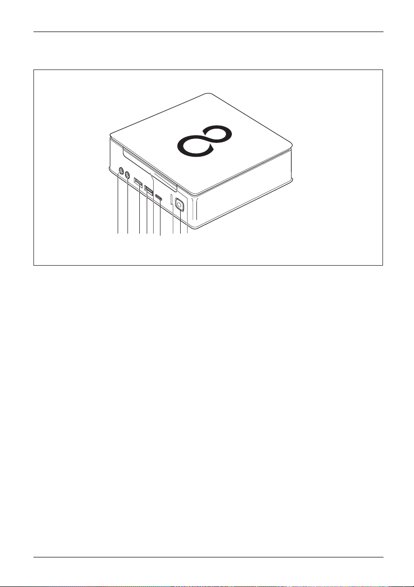
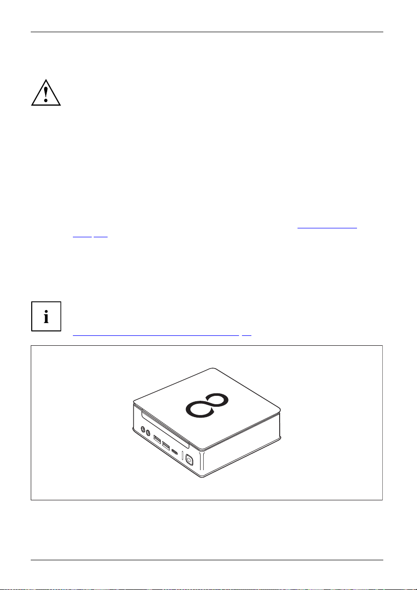
Device variant with the maximum of comp onents
12 34 76 8
1 = Microphone port
2 = Audio output
3 = USB port (USB 3.1, type A)
4 = USB port (USB 3.1, type A)
5 = Insert/eject button, optical drive (optional)
lled either an optical drive o r a SmartCard reader / palm
ard disk, mount the blanking plate.
tion on modifying the device and on installing and removing
tion "
System expansions", Page 60.
5
9
6 = USB port (USB 3.1 , type C) (optional)
7 = Hard disk indicator
8 = On/Off switch with power-on indicator
9 = Emergency removal
Fujitsu 9
Page 14

Ports and Operating Elements
Device variant with SmartCard reader and / or palm sensor
8 91 2 3 4 5 76 10
1 = Microphone port
2 = Audio output
3 = USB port (USB 3.1, type A)
4 = USB port (USB 3.1, type A)
5 = SmartCard reader (optional)
10 Fujitsu
6 = USB port (USB 3.1, type C) (optional)
7 = SmartCard reader indicator (optional)
8 = Hard disk indicator
9 = On/Off switch with power-on indicator
10 = Palm sensor (optional)
Page 15
Device variant with second hard disk
7 81 2 3 4 5 6
Ports and Operating Elem e n ts
9
1 = Microphone port
2 = Audio output
3 = USB port (USB 3.
4 = USB port (USB 3.1, type A)
5 = Removing seco
Fujitsu 11
1, type A)
nd hard disk (optional)
6 = USB port (USB 3.1
7 = Hard disk indicator
8 = On/Off switch w
9 = Hard disk indicator of second hard
disk (optional)
, type C) (optional)
ith power-on indicator
Page 16

Ports and Operating Elements
Rear
FUJITSU Desktop ESPRIMO Q556
14 13 12 10 9
1 = Latching clip (optional)
2 = Top casing cover unlocking mechanism
3 = Security lock device
4 = Padlock clamp
5 = LAN port
6 = PS/2 port
7 = Audio output
1
3 42
8 = 2 USB ports (USB 3.1)
9 = 2 USB ports (USB 2.0)
10 = Display port
11 = Bottom casing cover unlocking mechanism
12 = DVI-D monitor port
13 = Serial port
14 = Mains connection (AC IN)
5 6
711 8
12 Fujitsu
Page 17

FUJITSU Desktop ESPRIMO Q558
Ports and Operating Elem e n ts
14
1 = Latching clip (optional)
2 = Top casing cover unlocking mechanism
3 = Security lock device
4 = Padlock clamp
5 = LAN port
6 = 4 USB ports (USB 2.0)
7 = PS/2 port (optional)
13 12 10
1
3 42 7
5
6
811 9
8 = Audio output
9 = 2 USB ports (USB 3.1)
10 = Display ports
11 = Bottom casing cover unlocking mechanism
12 = DVI-D monitor port
13 = Serial interface (optional)
14 = Mains connection (AC IN)
Fujitsu 13
Page 18

Ports and Operating Elements
FUJITSU Desktop ESPRIMO Q957/Q958
14
1 = Latching clip (optional)
2 = Top casing cover unlocking mechanism
3 = Security lock device
4 = Padlock clamp
5 = LAN port
6=2USBports(USB2.0)
7 = PS/2 port (optional)
13 12 10
1
3 42 7
5
6
811 9
8 = Audio output
9 = 4 USB ports (USB 3.1)
10 = Display ports
11 = Bottom casing cover unlocking mechanism
12 = DVI-D monitor port
13 = Serial interface (optional)
14 = Mains connection (AC IN)
14 Fujitsu
Page 19
Important notes
ImportantnotesNotes
In this chapter you will find information regarding safety which it is essential to
take note of when working with your device.
Safety notes
SafetynotesNote
Please follow the safety
as well as the safety note
When installing and ope
ambient conditions in C
started", Page 17 or the no
When setting up the dev
thecasingreceives
cover the ventilati
You should operate
is the same as the lo
For c omplete disco
the mains plug out
Please note that c
of the device ma
The activities
Only qualified
at great risk o
Do not lay or p
Do not apply a
described in these instructions must always be performed with special care.
technicians should repair the device. Incorrect repairs could put the user
r cause serious damage to the equipment (electric shock, risk of fire).
lace any objects on the upper side of the device.
ny pressure to the upper side of the device during operation.
notes provided in the "Safety/Regulations" manual
s given below.
rating the device, please observe the notes on
hapter "
Technical data", Page 101 and Chapter "Getting
tes in the data sheets.
ice, make sure there is clearance all around it so that
enough ventilation. I n order to avoid overheating, do not
on areas on the monitor or the device.
the device only if the rated voltage of the device
cal mains voltage.
nnection from the mains voltage, you m ust pull
of the socket.
omponents in the syste m as w ell as the surface
y become very hot.
Important notes
Transport
tation
portation
DeviceTranspor
Re-trans
ing the device
Transport all devices separately in their original packaging or in a packaging
that protects them from knocks and jolts.
Unpack them only at the insta llation site.
If the device is brought from a cold environment into the room where it will be used,
condensation may occur. In order to avoid dama ge to the device, wait before preparing
it for use until the device has reached the ambient temp erature and it is absolutely dry.
Fujitsu 15
Page 20

Important notes
Cleaning the device
Device,Trans portationRetransportationSystemunit,see Device
Turn off all power and equipm ent switches and disconnect the power
plug from the m ains outlet.
Do not clean an y interior pa rts yourself, leave this job to a service technician.
Do not use any cleaning agents that contain abrasives or may corrode
plastic (alcohol, thinner or acetone).
Never clean the device with water! Water entering into the device could
present a serious risk to users (e.g. electric shock).
Ensure that no liquid enters the system.
The surface can be clea
moistened in mild dome
Use disinfectant wi
ned with a dry cloth. If particularly dirty, use a cloth that has been
stic detergent and then carefully w rung out.
pes to clean the keyboard and the mouse.
Energy-saving, disposal and recycling
DisposalSavingenergyRecycling
You c an findinformationonthesesubjectsinthe"Environment and Energy Information" manual
or on our website ("
Important notes on ESPRIMO Q957
In an unlikely extreme situation (CPU completely utilised and many external USB devices with
high current consumption connected to the ESPRIMO Q95x simultaneously), the internal CPU
frequency can be reduced to prevent a current overload. The mouse, keyboard, headphones
and similar devices are low current consumers and are not affected.
As soo n as the overload is ended, the CP U frequency returns to the normal value.
In the unlikely case of an extreme overload, the USB 3.1 port, type C, is deactivated and
a reset is carried out to limit the output level to 4.5 W (900 mA).
If an extreme system load occurs again, the USB 3.1 port, type C, will be permane ntly
deactivated. To prevent restricted performance or the deactivation of devices, the device
causing the overload must be stopped or the number of USB devices with high current
consumption and connected to the ESPRIMO must be reduced. .
The deactivated or throttled USB 3.1 port, type C, then automatically returns to full power
when the d evice is reconnected or the system is restarted.
http://www.fujitsu.com/fts/about/fts/environment-care/").
16 Fujitsu
Page 21

Getting started
Getting started
Gettingstarted
Unpacking and checking the delivery
It is recommended not to throw away the original packaging material! It may be
required for reshipment at some later date.
PackagingContentsofdeliveryPackaging,
► Unpack all the individual parts.
► Check the contents of the package for any visible damage caused during transport.
► Check whether the delivery c onfo rms to the details in the delivery note.
► Should you discover that the delivery does not correspond to the delivery
Steps for initial setup
Preparingforfirstuse,overvie wPreparingforuse,
Only a few steps are necessary to put you r new device into operation for the firs t time:
• Select a location for device and set up device
• Connect external devices such as mouse, keyboard and monitor
• Check the voltage at the mains outlet and connect the device to an electrical outlet
• Switch the device on
You will learn more about the individual steps in the following sections.
Please observe the safety information in the "Important notes", Page 15 chapter.
note, notify your local sales outlet immediately.
External devices
If you have received other external devices in addition to your own device (e.g.
a printer), do not connect these until after the initial installation. The following
sections describe how to connect these external devices.
Drives and boards
If you have received drives or boards with your device, please do not install
them until after first-time setup. How to install drives and boards is described
System expansions", Page 60 chapter.
in the "
Fujitsu 17
Page 22
Getting started
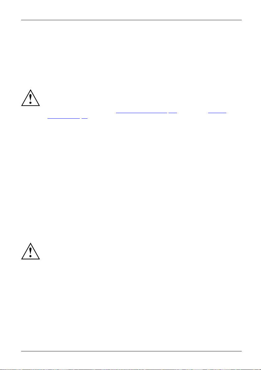
Fitting the underside cover (device-dependent)
Rating type plate
FUJITSU Desktop ESPRIMO Q956/Q957:
At the time of device delivery, the bottom cover (2) is not yet mounted on the bottom
of the device, but packed along with the system so that you can read the type rating
plate (3) and the software licence information when preparing it for use.
The type rating plate and the softwa re licence are affixed on the device cover and
is usually located below the mounted bottom cover so that it is not visible.
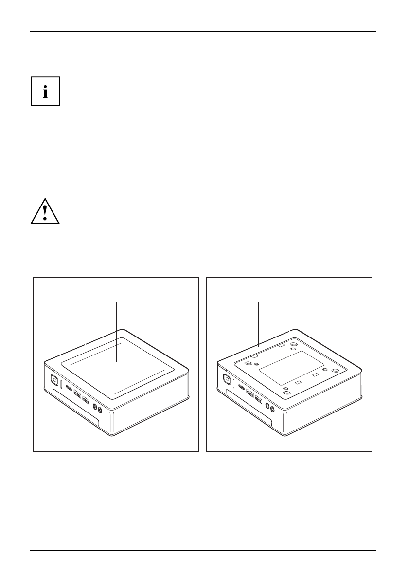
FUJITSU Desktop ESPRIMO Q55x/Q958:
With the FUJITSU Desktop ESPRIMO Q55x, the type rating plate is attached to the
underside of the device or to the right side of the device (w hen used vertica lly).
FUJITSU Desktop ESP
Only fit the undersi
vertical operatin
Section "
If you are fitting t
must not fit the und
attachment will
e with device cover (1), with bottom cover
Devic
ed (2)
mount
Setting u
de cover if you are u sing the device in a horizontal or
g position without attaching it to a VESA interface (see
p the device", Page 20).
he device onto the VESA interface of a monitor, you
erside cover. If you do, the screw holes for the VESA
no longer be accessible.
21 31
RIMO Q 956/Q 957:
Devic
plate
cover
e with device cover (1) and visible type
(3, ESPRIMO Q956/Q967 only), no bottom
.
The device has a device cover (1) at the bottom. The device cover is divided into two:
during operation, the bottom cover (2) is inserted in the device cover.
In order to be able to mount the bottom cover prior to preparing it for use, proceed as follows:
18 Fujitsu
Page 23

Getting started
► Turn the device over and place it on a stable, flat and clean surface. If necessary, place a
slip-resistant cloth on this surface to prevent the device from being scratched.
2
1
1
► Put the bottom cover as shown on the bottom of the device.
► Hook th e bottom cover in the openings provided for this purpose at the bottom (1).
► Fold the cover in the direction of the arrow (2) until it engages noticeably and audibly.
Information about removing the bottom cover is provided in Section "
Page 26.
Remove the bottom cover",
Fujitsu 19
Page 24
Getting started
Setting up the device
VideoworkstationErgonomicDevice
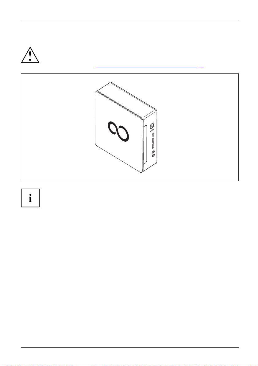
Operating position
You can use the device in various operating positions.
Horizontal, top casing cover upwards
When setting up your device, please read the recommendations and
safety notes in the "Safety/regulations" manual.
We recommend that you place your device on a surface with good anti-slip qualities.
In view of the multitude of different finishes and varnishes used on furniture, it is
possible that the rubber feet will mark the surface they stand on.
Depending on the location of your device, bothersome vibrations and noises may
occur. To prevent this, a distance of at least 10 mm / 0.39 inch should be maintained
from other devices or objects on casing sides without ventilation areas.
In order to avoid overheating, do not cover the ventilation areas
on the monitor or the device.
A minimum distance of 200 mm / 7.87 inch from the device must
be observed for ventilation areas.
Do not place multiple devices on one another and do not keep any monitor on the d evice.
Do not e xpo se the device to extreme ambient conditions (see "
Page 101, "Ambient conditions"). Protect the device from dust, humidity, and heat.
With the FUJITSU Desktop ESPRIMO Q55x/Q957/Q958 device version, you
will need to affix the adhesive feet you were supplied with to the four corners
of the underside of the device in this opera ting position, refer to Section
Attaching the adhesive feet (optional)", Page 24.
"
Technical data",
20 Fujitsu
Page 25
Vertical with no base, ON/OFF switch facing upwards
If you are not using a base, you will need to affix the adhesive feet you w ere
supplied with to the four corners of the left side of the device (side with screw holes
for attaching the base). Affix the adhesive feet in such a way that no fan vents are
covered (see S ection "
Attaching the adhesive feet (optional)", Page 24).
Operation in th e vertical operating position is not allowed in Taiwan.
Getting started
Fujitsu 21
Page 26

Getting started
Vertical with base, ON/OFF switch facing upwards
For mounting, refer to Section "
Fitting the base (optional)", Page 25
22 Fujitsu
Page 27
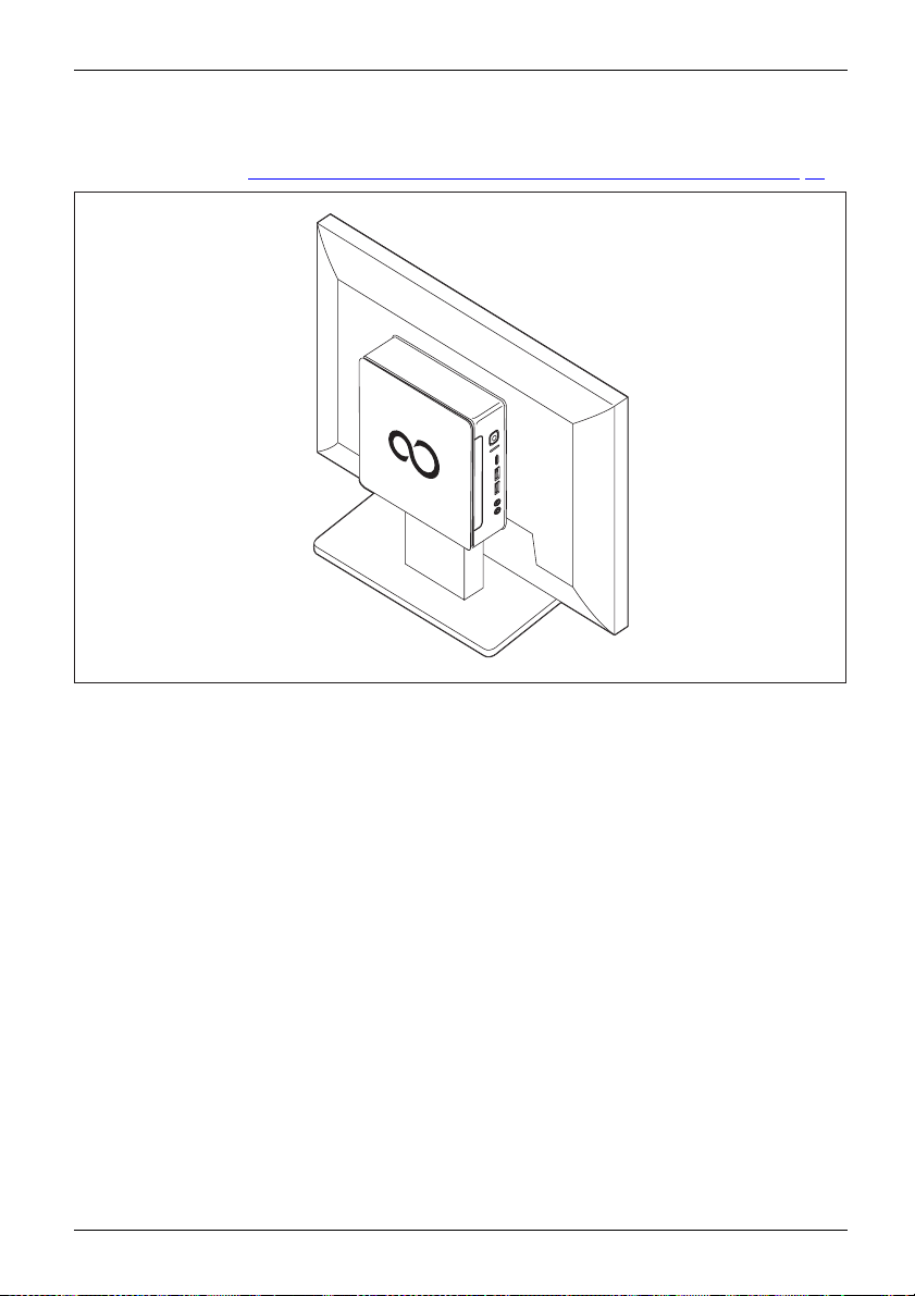
On the VESA interface of a monitor, ON/OFF switch facing upwards
For fitting see Section "
Fitting the device to the VESA interface on a monitor (optional)", Pag e 26
Getting started
Fujitsu 23
Page 28
Getting started
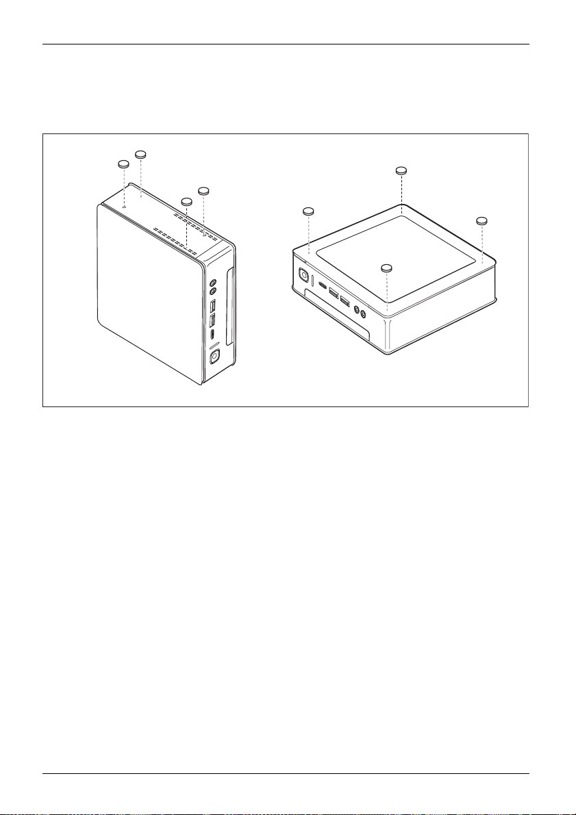
Attaching the adhesive feet (optional)
With the horizontal and vertical operating positions with no base, you will need
to attach the adhesive feet to the device.
1
1
1
1
2
2
2
2
► Vertical opera
of the left sid
Affix the adhes
► Horizontal operating position with no base: Position the adhesive feet on the four
corners of the underside of the device as illustrated (2).
24 Fujitsu
ting position with no base: Position the adhesive feet on the four corners
e of the device as illustrated (side with scre w holes for attaching the base).
ive feet in such a way that no fan vents are covered.
Page 29

Fitting the base (optional)
Screw holes for attaching the base can only be found on the left side of the device.
4
3
Getting started
2
1
1
2
► Place the devic
The screw holes (1) and guide openings (2) for securing the base on the
left side of the device are facing upwards.
► Place the base
correspondin
► Place the screws into the overlapping screw holes (1 & 4) and attached
the base to the device using the screws.
e on the right side as shown.
on the left side of the device such that the locking lugs (3) are inserted into the
g guide openings (2) on the device and the screw holes (1) and (4) directly overlap.
3
4
Fujitsu 25
Page 30

Getting started
Fitting the device to the VESA interface on a monitor (optional)
With ESPRIMO Q956/957 type devices, the casing cover is already fitted
with the corresponding screw holes by default.
With ESPRIMO Q55x/Q958 type devices, you can order the corresponding
casing cover with screw holes separately if necessary.
The device must be fitted onto the screen in such a way that the connecting
and operating elements can be used from the side.
Remove the bottom cover
• Requirement: The casing is opened and the casing cover is removed (refer to
Remove the casing bottom cover", Page 97).
"
1
1
2
► Release th e locking lug (1) on the underside cover from the casing cover
and remove the underside cover (2).
Information about fixing the underside cover is provided in Section "
underside cover (device-dependent)", Page 18.
26 Fujitsu
Fitting the
Page 31

Mounting with screws
a
Getting started
1
1
1
1
► Mount the casi
Fujitsu 27
ng cover (a) into the bolts at the rear of the monitor using the screws (1) supplied.
Page 32

Getting started
► Secure the device on the casing cover mounted on the monitor.
28 Fujitsu
Page 33

Mounting with bolts and screws
1
1
Getting started
1
1
► Screw in the fo
Fujitsu 29
ur hexagon head bolts at the rear of the monitor (1).
Page 34

Getting started
1
1
a
1
1
► Install the casing co ver (a) into the bolts at the rear of the monitor using the screws supplied (1).
30 Fujitsu
Page 35

► Secure the device on the casing cover mounted on the m o nitor.
Getting started
Mounting on monitors with height-adjustable column
► Detach all cables from the monitor.
► Fix the monitor base adapter by laying the
Velcro tape around the monitor base (1) and
looping it back through the metal eye ( 2).
2
2
1
Fujitsu 31
Page 36

Getting started
2
► Fix the casing cover onto the monitor base
adapter using the screws (1) supplied.
1
1
1
1
► Secure the device on the casing cover
mounted on the monitor.
32 Fujitsu
Page 37

Connecting the power cable
PreparingforoperationPowercable
Observe t he safety notes in the enclosed "Safety/Regulations" manual.
The supplied power cable confo rms to the requirements of the country in
which you purchased your device. Make sure that the power cable is approved
for use in the country in which you intend to use it.
Use the following table to check which mains plug applies for your country. The
following illustration may be different from your country variant.
1
Getting started
2
► Connect the power cable (1) to the power connector (AC IN) of the device.
► Connect the mains cable (2) to a mains socket.
Fujitsu 33
Page 38

Getting started
Power connector
Country
USA, Canada, Mexico, parts of So
Japan, Korea, the Philippines,
Russia and the Commonweal
States (CIS), large parts
South America, the Middl
Hong Kong, India, large p
of Europe, parts of
e East, parts of Africa,
arts of South Asia,
uth America,
Taiwan
th of Independent
UK, Ireland, Malaysia, Singapore, parts of Africa,
China, Australia and New Zealand
34 Fujitsu
Page 39

Getting started
Connecting external devices
Read the docu m entation on the external device before connecting it.
With the exception of USB devices, always remove all power plugs
before connecting external devices!
Do not connect or disconnect cables during a thunderstorm.
Always h old the plug of a cable when removing it. Never unplug a
cable by pulling the cable itself.
To ensure that your device works properly, use only the connection cable
supplied or use a high-quality connection cable.
Ports on t he device
PortsExternaldevicesDevice
The ports are located on the front and back of the device. The ports available on your
device depend on the configuration level you have selected. The s tandard ports are
marked with the symbols shown below (or similar). Detailed information on the location
of the connections is pro vided in the m anual for the mothe rboard.
DVI-D monitor port, white
Monitorport
DP Display port
Serial port
Serialport
USB 2.0 - Universal Serial
Bus, type A, black
UniversalSerialBus
USB 3.1 Gen1 - Universal
Serial Bus, Type A: blue, Type
C: black
UniversalSerialBus
LAN port
LANport
Audio input (Line in)
Audio output (Line Out), light green
AudiooutputLineout
USB 3.1 Gen2 - Universal
Serial Bus, type A: blue, type
C: black
PS/2 keyboard port, purple
Keyboardport
Some of the connected devices require special software (e.g. drivers) (refer to the
documentation for the connected device and Operating System).
Fujitsu 35
Page 40

Getting started
Connecting the monitor
Connect the monitor to your device only if it is switched off.
► Follow the instructions contained in the monitor operating manual to prepare
the monitor (e.g. connecting cables).
Monitor
► Plug the data cable into the desired monitor port of the device.
► Plug the monitor power cable into the grou nded mains outlet.
Connecting a USB mouse
► Connect the USB mouse to one of the USB ports on the device.
ConnectingaUSBmouseUSBport
Connecting a USB keyb
Use th e keyboard cable provided with the keyboard (not included in the delivery scope of the device).
USBportconnecting
► Plug the rectangular co nnector of the keyboard cable into the rectangular socket
on the underside or on the rear of the keyboard.
► Plug the fl at rectan
USBport
Connecting external devices to the serial interface
SerialinterfaceSerialinterface,Externaldevices,Devices,
For an exact description of how to connect external devices to the corresponding
port, please see the external device documentation.
gular USB co nnector of the keyboard cable into a USB port of the device.
oard
External devi
► Connect the da
ces (e.g. a printer or scanner ) can be connected to the serial port.
ta cable to the external device.
► Connect the data cable to the corresponding serial interface.
Port settin
Serialinterface,
Device drivers
Devicedrivers,
gs
You can change the settings of the port in th e BIOS Setup.
The devices connected to the serial interface req uire drivers. Your operating system
already includes many drivers. If the required drive is missing, install it. The latest
drivers are usually available on the Internet or will be supplied on a data carrier.
36 Fujitsu
Page 41

Connecting external devices to the USB ports
USBdevicesUSBportExternaldevicesDevices
You can connect a wide range of external devices to the USB ports (e.g.
printer, scanner, modem or keyboard).
USB devices and hot plug-enabled. This means you can connect and disconnect
USB cables while your device is switched on.
Additional information can be found in the documentation for the USB devices.
► Connect the data cable to the external device.
► Connect the data cable to one of the USB ports on your d evice.
Device drivers
External USB devices which you connect to one of the USB ports don’t usually
need their own drivers because the software required is already included in
the Operating System. If the device requires separate software, please follow
the instructions in the manufacturer’s documentation.
Getting started
Connecting a PS/2 d
Only use the supplied lead.
A PS/2 device is only recognised by the PC if you conn ect the PS/2 device
when the PC is switched off and then switched on again.
ConnectingaPS/2deviceconnecting
► Connect the PS/2 device to the PS/2 port on the PC.
► Switch the PC back on.
evice
Fujitsu 37
Page 42

Getting started
Initial switch-on: Software will be installed
InstallationSoftwareInstallation
Once the installation has been started the device must not be switched
off, unless the installation has been completed.
During the installation process, D O NOT restart the device unless
you are requested to do so!
Otherwise the installation will not be carried out correctly an d the contents
of the hard disk will have to be completely restored.
If the device is integra
the network protocol ar
Contact your network a
When you switch on the d
is installed and confi
as this process must
You may need the lic
locatedonastick
er on your device (see "
ence number for Windows during the installation. The licence number is
ted into a network, the user and server details as well as
e required during the software installation.
dministrator if you have any questions about these settings.
evice for the first time, the supplied software
gured. Plan a reasonable amount of time for this,
not b e interrupted.
Remove the bottom cover", Page 26).
Switch on the m onitor and the machine
In order to avoid overheating, do not cover the ventilation areas
on the monitor or the device.
► Switch on the monitor (see operating instructions for the monitor).
► Pres
38 Fujitsu
s the on/off button on the front of the machine.
The operational display will light up and the machine will start.
Page 43

Getting started
Installing the software
► During installation, follow the instructions on the screen.
SoftwareInstallation
► Consult the Operating System manual if there is anything unclear about the requested input data.
You will find detailed information on the system, as well as drivers, utilities and updates
on the "Drivers & Utilities" DVD and on the Internet at "
http://www.fujitsu.com/fts/support".
Fujitsu 39
Page 44

Operation
Operation
Switch the device on
► If necessary, sw itch the monitor o n (see the operating manual for the monitor).
DeviceMonitor
► Press the ON/OFF switch on t
The power indicator glows and the device is started.
Switching the device off
► Shut down the Operatin
DeviceMonitor
► If the Operating System does not automatically switch the device into energy-saving
mode or switch it off, press the ON/OFF switch until the device s witches off.
Warning, this could lead to a loss of data!
If the device is swi
The on/off switch
disconnect the ma
► If necessary, switch the monitor off (refer to the operating manual for the monitor).
tched off, it consumes a minimum of energy.
he front of the device.
g System properly.
does not disconnect the device from the mains voltage. To completely
ins voltage, pull the power plug out of the power socket.
40 Fujitsu
Page 45

Indicators on the device
The indicators are o n the front of the casing. Which indicators are available on your
device depends on the configuration level you have selected.
Example: Device variant with SmartCard reader and/or palm sensor
321
No. indicator Description
1
SmartCard read
indicator (dev
dependent)
2 Hard disk indi
3 Power indic
ator
er
ice
cator
The indicator l
accessed (devi
The indicator
is being acce
Attention:
disconnect
• Indicator
The device is switched on.
• Indicato
The device is in energy-saving mode. After being switched on
with the On/Off switch, the device powers up or returns to the
state it was in before it entered energy-saving mode.
• The indi
The device is switched off (disconnected from the mains) or
is ready. If the device is ready it can be switched on with the
On/Off switch.
ights up when the device’s SmartCard reader is
ce depen dent).
lights up when the hard disk drive in the device
ssed.
In the energy saving mode, the device must not be
ed from the mains, as this can result in data loss.
is illuminated:
r flashes:
cator is not illuminated:
Operation
In the energy saving mode, the device must not be disconnected from
the mains, as this can result in data loss.
Fujitsu 41
Page 46

Operation
Keyboard
KeyboardKeyboardKeyboardKeyboardKeyboardKeyboardAlphanum er ickeypadCursorkeysButtonsFunctionkeysNumerickeypadNumerickeypad
The illustrated keyboard is an example and may differ from the model you use.
1 2
345
1 = Function keys
2 = Power button (optional)
4=Cursorkeys
5 = Numeric keyp ad (calculator keypad)
3 = Alphanumeric keypad
Important k
KeysKeycombinations
eys and key combinations
The description of the following keys and key combinations applies to Microsoft
operating systems. Details of other keys and key combinations ca n be found in the
documentation of the relevant application programme.
Key / key combination Description
tch
On/Offswi
Key
Power button (op tional)
Depending on the setting in the BIOS Setup the device can be switched on
or off with this switch. Some operating systems allow you to configure
additional functions of the ON/OFF switch in the Control Panel.
WithsomekeyboardstheON/OFFswitchcanonlybeusedwithanACPI
(Advanced Configuration and Power Management Interface). Otherwise
the key is inoperative. The motherboard must support this function.
KeysKeysKeys
Enter key
Confirm the highlighted se lection. The enter key is also referred to as
the "Return" key.
42 Fujitsu
Page 47

Operation
Key / key combination Description
Keys
Windows key (device-dependent
calls up the Windows Start menu
Keys
Menu key (device-dependent: Variant 1))
calls up the menu for the marked item (Windows).
Keys
Windows key (device-dependent: Variant 2)
The Windows key switches between the start screen and the last used
application.
Keys
Menu key (device-dependent: Variant 2)
The Menu key opens the menu for the active application.
KeysKeys
Shift key
enables upper-case letters and the upper key symbols to be displayed.
The Shift key is a lso called "Shift".
Keys
Alt Gr key (country-dependent)
produces a character shown on the bottom right of a key (e.g. the @
sign on the
Keys
Num Lock key
By pressing the Num Lock key you switch between the upper- and
lower-case levels of the calculator keypad.
When the Num Lock indicator is lit the digit and comma keys are active.
When the Num Lock indicator is not lit the cursor control functions are
active in the Numeric keypad.
KeysKeysKeysKeys
Ctrl key
Ctrl
performs a
key. The
+Del
+Del
nations
Ctrl+Alt
Ctrl+Alt
KeysKeycombi
Ctrl
Windows Security/Task Manager
Del
AltCtrl
++
This key combination opens the Windows Security/Task Manager window.
:Variant1)
.
Q
key).
special operation when pressed in conjunction with another
y is also called the "Control" or "Control k ey".
ke
Fujitsu 43
Page 48

Operation
Optical drive (device-dependent)
Opticaldrive
Handling storage media
Storagemedia
Observe the following guidelines when h andling storage media:
• Avoid touching the surface of any storage media. Handle storage media only by their edges.
• Always keep the storage media in its case. This will protect the storage media against
• Protect your storage m ed ia against dust, mechanical vibrations and direct sunlight.
• Avoid keeping storage media in areas subject to high temperatures or humidity.
You can use 12 cm diameter storage media in the drive. Do not use any
visiting card CDs or other small storage media.
When using a CD of poor quality vibrations and reading errors may occur.
Depending on the device variant, your device is fitted with an optical drive.
An optical drive on one side and a SmartCard reader/palm sensor on the
other cannot be combined with one another.
This product contains a light-emitting diode (LED), classified in accordance with IEC
60825-1:2007: LASER CLASS 1, and hence, it should not be opened.
being covered in dust, scratched or da maged in any other way.
44 Fujitsu
Page 49

Inserting or removing storage media
► Press the Insert/Eject button to open the tray.
The drive tray will open.
► Place the storage media in the tra y with
the printed side facing upwards.
1
or
► Remove any storage media
Operation
already in there.
2
If you press
in the optic
the proces
Fujitsu 45
the Remove button while the storage media is being accessed
al drive, the storage media is not output autom atically. Wait until
s has completed and try once again.
Page 50

Operation
Manual removal of storage media (emergency removal)
CD/DVDRemoving byh and, CD/DVDEmergencyremoval,CD/DVD
In the event of a power failure or damage to the drive it may be necessary
to manually remove the CD/DVD.
► Switch your device off.
► Push a pen or a piece of wire (such as a
paper clip) firmly into the opening (1).
The drive tray is ejected. You can now pull
the drive tray (2) out of the drive.
2
1
Wireless LAN / Bluetooth wireless components (device-dependent)
The installation of wireless components not approved by Fujitsu will
invalidate the certifications issued for this device.
The operation of these wireless components is not permissible in Taiwan.
Switching the wireless components on and off
With the programme Device Manager you can switch off the wireless
components on or off separately.
Pay a ttention to the additional safety notes for device s with wireless components
provided in the "Safety/Regulations" manual.
Details on using Wireless LAN can be found in the online help system
included with the Wireless LAN software.
You ca n find more information on how to use Bluetooth on the CD you
received with your Bluetooth software.
46 Fujitsu
Page 51

Settings in BIOS Setup Utility
BIOSSetupUtilitySystemsettings,BIOSSetupUtilityConfiguration,BIOSSetupUtilitySetupConfiguringthesystemConfiguringthehardware
With the help of the BIOS Setup Utility you can adjust the system functions
and the hardwa re configuration for your device.
When it is supplied, the device is set to factory default settings. You can change these
settings in BIOS Setup Utility. Any changes you make in the settings take effect as
soon as you save and shut down the BIOS Setup Utility.
The BIOS Setup Utility program contains the following menus:
Menu Description
Main
Advanced
Boot
Power
Security
Exit
System settings such as
Advanced system setti
Configuration of the start-up sequence
Power management functions
Password settings
Exits the BIOS Set
The fo llowing function keys can also be used:
Key Description
Esc
to sh ut down the BIOS Setup Utility
The current settings are not saved.
F7
To discard changes and to load the previous configuration of the BIOS
Setup Utility.
F9
F10
To load the d
to sh ut dow
The curren
efault configuration of the BIOS Setup Utility.
ntheBIOS Setup Utility
t settings are saved.
time and date
ngs
and security functions
up Utility
Operation
Startin
► Start the device (switch off/on or reboot the Operating System).
gtheBIOSSetupUtility
BIOSSetupUtility
ing on the setting for Fast Boot in the BIOS Setup Utility the following display,
Depend
icable, appears on the screen on start-up:
if appl
<F2> BIOS Setup <F12> Boot Menu
► Press the function key
► If a p
assword has been assigned, enter the password and press the Enter key.
u have forgotten the password, contact your system administrator
If yo
ontact our customer service centre.
or c
F2
.
The BIOS Setup Utility starts.
Fujitsu 47
Page 52

Operation
Operating the BIOS Setup Utility
BIOSSetupUtility
Press the
F1
key to display help on the operation of the BIOS Setup Utility. The description
of the i ndividual settings is s hown in the right-hand window of the BIOS Setup Utility.
With the
F9
key you can load the default settings of the BIOS Setup Utility.
► Use the cursor keys
The menu is displayed on the screen.
←or→
► Select the op tion that you want to change with the cursor keys
to select the menu in which you would like to configure settings.
↑
or↓.
► Press the Enter key.
► Press the
ESC
key to exit the selected menu.
► For future reference, make a note of the changes you have made (e.g. in this manual).
Shutting down the BIOS Setup Utility
BIOSSetupUtility
You need to select the desired option in the Exit menu and activate it by pressing the Enter key:
Exit Saving Changes - save changes and exit BIOS Setup Utility
► To save the current menu settings and to shut down the BIOS Setup Utility,
select Exit Saving Changes and Yes.
The device is rebooted and the new se ttings come into effect.
Exit Discarding Changes - Reject changes and exit BIOS Setup Utility
► To discard the changes, select Exit Discarding Changes and Yes.
ThesettingswhichwereinforcewhenBIOS Setup Utility was called continue to remain
effective. The BIOS Setup Utility is shut down and the device is rebooted.
48 Fujitsu
Page 53

Operation
Property and data protection
PropertyprotectionDataprotectionSecuritymeasures
Software functions and mechanical locking offer a broad range of functions for protecting your device
and your personal data against theft and unauthorised access. You can also combine these functions.
BIOS Setup security functions
In the BIOS Setup themenuonSecurity offers you various options for protecting
your personal data from unauthorised access, e.g.:
• preventing unauthorised system access
• preventing opening the BIOS Setup without authorisation
Before using the various options of password protection for your data security
in the BIOS Setup Utility, please note the following:
Make a note of the passwords and keep them in a safe place. If you forget your
supervisor password, you will not be able to access your device. Deleting the password
is not covered by warranty and assistance for rectifying this will be charged separately.
on
Passwordprotecti
Your password can be
No distinction is m
Using the SmartCard reader (device-dependent)
SecurityfunctionsSecurityfunctions
Whether your device has a SmartCard reader depends on the
device variant you have ordered.
up to 32 characters long and can contain letters and numbers.
ade between upper-case and lower-case.
The SmartCard reader allows access to be limited to only those users that
have an appropriate SmartCard .
SmartCards are not supplied as standard equipment. You can use all SmartCards that comply with
the ISO standard 7816-1, -2 or -3. These S martCards are available from various manufacturers.
With the appropriate software y ou can use your SmartCard as an alternative to password protection,
but also as a digital signature, for encrypting your e-mails or for home banking.
We recom mend that you always use two SmartCards. Always keep one of the SmartCards
in a safe place if you are carrying the other SmartCard w ith you.
In order to be able to take advantage of all the security features of your system, you
will need a CardOS SmartCard from Fujitsu Technology Solutions.
The SmartCard can only be used with a PIN so maximum protection is maintained
even when the SmartCard is lost. In order to maximise your security, the CardOS
SmartCard gets disabled if three incorrect attempts are made to enter th e PIN.
When using your CardOS SmartCard for the first time, you have to enter the preset PIN
"12345678" or the PIN that has been informed to you by your system administrator.
Fujitsu 49
Page 54

Operation
Mounting the SmartCard reader
Mount the SmartCard reader as described in section "Installing and rem oving the
SmartCard reader and palm sen sor (device-dependent)", Pa ge 85.
Inserting the SmartCard
Do not use force when inserting and removing the SmartCard.
Make sure that foreign objects do not fall into the SmartCard reader.
1
► Push the SmartCard into the SmartCard reader with the chip facing upwards.
50 Fujitsu
Page 55

Operation
Using a palm sensor (device-dependent)
Whether your device has a palm sensor depend s on the device variant you have ordered.
The palm sensor (1) can record the image of the pattern of the veins in the hand. This image
is evaluated by additional software and can be used instead of a password.
1
Mounting the palm sensor
Mount the palm sensor as described in Section "Installing and removing the
SmartCard reader and palm sens or (device-dependent)", Page 85.
Using the palm sensor
► To be able to use the palm sensor, yo u must install and launch the software.
► Follow the instructions on the screen.
The surface of the hand must be positioned such that the palm of the hand
lies centrally over the palm sensor. In doing so, the palm of the hand and
slightly spread fingers should form an even surface.
The supplied software shows the precise position of the hand above the palm sensor.
Fujitsu 51
Page 56

Operation
Using the security lock
The following Figure shows the FUJITSU Desktop ESPRIMO Q95x device
variant. You will find the security lock device in the same position in the
FUJITSU Desktop ESPRIMO Q 55x/Q 958 device variant.
Your device has provision for a security lock (1). Using the security lock device and
the Kensington Lock cable (steel cable, accessory) you can protect your device against
theft. Please consult the manual for your Kensington Lock.
1
► Attach the Ken
KensingtonLockcableUsingtheSecurityLockMechanicallockMechanicallockAnti-theftprotection
sington Lock cable to the Security Lock mechanism (1) on your device.
52 Fujitsu
Page 57

Operation
Using a locking slide
• The top casing cover has been removed (see "Removing the casing top cov er", Page 66).
• The bottom casing cover has been removed (see "
the bottom casing co ver", Page 97).
You can also purchase a locking bracket for your device. Contact the service
desk or sales partner responsible for your country.
The following Figure illustrates the FUJITSU Desktop ESPRIMO Q956/Q957
device variant. In the FUJITSU Desktop ESPRIMO Q55x/Q958 variant, th e
concerned components are located in the same position.
Removing and attaching
You can use the padlock c
protect yo ur device fro
m unauthorised opening.
lamp located on the device and the locking bracket to
Fujitsu 53
Page 58

Operation
► Pull the locking slide apart slightly (1).
PadlockclampLatchingclipMechanicalbackupMechanicallock
1
1
2
3
3
2
► Insert th
► Secure the bottom casing cover again, see "
► Secure t
e latching clip into the e y e s (2) in the direction of the arrow (3).
Securing the bottom casing cover", Page 98.
he top casing cover again, see "
Securing the top cas ing cover", Page 67.
54 Fujitsu
Page 59

► Fold the locking latching clip fully to the right until it is lying aga inst the rear of
the device and secure a padlock to the padlock clamp.
Alternatively you can use a Kensington Lock cable (see "Using the
security lock", Page 52). This will prevent unauthorised opening of the
latching clip and, with it, the casing cover.
Lead-sealing the casing
To prevent una uthorised persons from opening the casing, the casing can be lead-sealed.
► Use the wire of the lead-seal to connect the locking bracket with the pad lock clip
on the back of the device (see chapter "
hain
ire
lock
Lead-sealingLead-sealc
Lead-sealw
Mechanical
► Use the seal to secure the lead-sealing chain or wire.
Rear", Page 12).
Operation
Fujitsu 55
Page 60

Troubleshooting and tips
Troubleshooting and tips
Refer to the safety notes in the "Safety/regulations" m anual and in the "Getting
started", Page 17 chapter when connecting or disconnecting cables.
If a fault occurs, t ry to c
• in this chapter
• in the documentation for the connected devices
• in the help systems of th
• in the documentation for your operating system
orrect it as described in the following documentation:
esoftwareused
Help if problems occur
Should you encount
► Note the Ident-No
the underside of t
If necessary, rem
► Contact the Service Desk responsible for your country for clarification of the problem:
"
http://support.ts.fujitsu.com/contact/serv icedesk". When you do this, please have
ready the Ident-No. and serial number of y our system.
er a problem with your computer that you cannot resolve yourself:
. of your device. The Ident-No can be found on the type rating plate on
he device (see "
ove the type rating plate in order to access the Ident-No..
Fitting the underside cover (device-dependent)", Page 18).
Troubleshooting
Power-on indicator remains unlit after you have switched on your device
Cause
The mains voltage supply is faulty. ► Check whether the power cable is plugged
Internal power supply overloaded.
Troubleshooting
properly into the device and a grounded
mains outlet.
► Unplug th e mains plug of the device from
the mains socket.
► Wait for
► Insert the power plug into a properly
grounded mains outlet again.
► Switc
about 3 minutes.
h the device on.
56 Fujitsu
Page 61

Troubleshooting and tips
The device cannot be switched off with the On/Off switch.
Cause
System crash ► Press the On/Off switch for at least
Troubleshooting
4 seconds, until the device switches off.
Attention: Warning, this could lead to a loss of
data!
The Operating System is not shut-down properly
in the process. Error messages are therefore
possible the next time the system is booted.
Monitor remains blank
Cause
Monitor is switched off. ► Switch the monitor on.
Power saving has been activated (screen is
blank)
Brightness control is set to dark ► Adjust the brightness control. For detailed
Power cable not connected
Monitor cable not connected
Incorrect setting for the monitor
Troubleshooting
► Press any key on the keyboard.
or
► Deactivate the screen saver. If
necessary, enter the appropriate
password.
information, please refer to the operating
manual supplied with your monitor.
► Switch off the monitor and the device.
► Check that the monitor power cable is
properly connected to the monitor and to
a grounded mains outlet or to the monitor
socket of the device.
► Check that the device power cable is
properly plugged into the device and a
grounded m ains outlet.
► Switch on the monitor and the device.
► Switch of
► Check that the monitor cable is properly
connected to the device and monitor.
► Switch o
► Restar
► Press the
booting.
► Start
► Set the correct values for the connected
monitor as described in the operating
manual of your monitor.
f the monitor and the device.
n the monitor and the device.
t the system.
F8
key while the system is
the system in Safe mode.
Fujitsu 57
Page 62

Troubleshooting and tips
No mouse pointer displayed on the monitor
Cause
The mouse is not properly connected.
Troubleshooting
► Shut down the Operating System correctly.
► Switch the device off.
► Check that the mouse cable is properly
connected. If you are using an adapter or
extension lead for the mouse cable, check
the plug-in connection.
► Make sure that only one mouse is
connected.
► Switch the device on.
Date and time are not correct
Cause
Date and time are set incorrectly.
Troubleshooting
► Set the correct time and date under the
Operating System you are using.
or
► In the BIOS Setup, set the date or time.
SmartCard reader is not recognised
Cause
Chip card inserted incorrectly. ► Check whether you have inserted your
Troubleshooting
SmartCard into the SmartCard reader the
right way with the chip facing upwards.
► Check whether the SmartCard you are using
is supported. Your SmartCard must comply
with the ISO sta ndard 7816-1, -2, -3 and -4.
SmartCard PIN forgotten
Cause
PIN forgotten ► If you are working in a network, contact your
Troubleshooting
system administrator, who can unlock y our
system with a Supervisor PIN.
SmartCard lost
Cause
SmartCard lost ► If you are working in a network, contact your
58 Fujitsu
Troubleshooting
system administrator, who can boot your
system with a Supervisor SmartCard.
Page 63

Troubleshooting and tips
User an d/or supervisor SmartCard lost
Cause
User and/or supervisor SmartCard lost. ► If you have lost your User SmartCard, you
Troubleshooting
can continue working with the Supervisor
SmartCard and initialise a new User
SmartCard or deactivate the SystemLock
function.
► If you have lost the Supervisor SmartCard,
you can also continue working, but you no
longer have all rights and cannot initialise
another Supervisor-SmartCard.
► If you have lost both SmartCards, you
cannot boot your system. Please contact
our Service Desk. You must provide proof of
ownership for the device. Then the Service
Desk will refer you to our service partner,
who will unlock your device (for a charge).
Error messages on the screen
Error messages and their explanations are provided:
• in the technical manual for the mainboard
• in the documentation for the programs used
Installing new software
When installing programs or d rivers, important files may be overwritten and modified. To
be able to access the original data in the event of any problems following installation,
you should backup your hard disk prior to installation.
Tips
Topic Tip
Outofsystemresources ► Close unnecessary applications.
or
► Run the applications in a different order.
Fujitsu 59
Page 64

System expansions
System expansions
Upgrades,Device,Systeme xpansionComponentsServicing
After consulting the Hotline/Help Desk, you may remove and install the components
described in this manual yourself.
The following illustrations may differ slightly from your device, depending on its configuration level.
If further docu mentation was delivered with your device, please also read this through carefully.
In addition, before removing or installing system components, please pay attention to the following:
Repairs to the device must only be performed by qualified technicians. Incorrect repairs
may greatly endanger the user (electric shock, fire risk) and will invalidate your warranty.
As the device has to be shut down in order to install/deinstall system hardware
components, it is a good idea to print out the relevant sections of this chapter beforehand.
The device must be switched off when installing/rem oving the system
expansions and may not be in energy-saving m ode.
Remove the power plug before opening the device.
Be careful that no wires become trapped when removing or installing components.
When installing components that become very hot, make sure that the maximum
permissible tem peratu re of the component s in operation is not exceeded.
An update of the BIOS may be required for a system expansion or ha rdware
upgrade. Further information can be found in the BIOS help section or if
necessary in th e Technical Manual for the mainboard.
60 Fujitsu
Page 65

System expansions
Information about boards
Take care with the locking mechanisms (catches and centring pins) when you
are replacing boards or components on boards.
Note that some components on the mainboard may be very hot if the device was
in use shortly before the casing was removed.
To prevent damage to the board or the components and conductors on it, please take care when
you insert or remove boards. Make sure expansion boards are inserted straightly.
Never use sharp objects (screwdrivers) for leverage.
Boards with electrostat
shown.
When handling boards fit
following points:
• You must always disc
object) before work
• The equipment and tools you use must be free of static charg es.
• Only touch or hold t
marked green (Touc
• Never touch pins or conductors on boards fitted with ESDs.
ic sensitive devices (ESD) are identifiable by th e label
ted with ESDs, you must always observe the
harge static build up (e.g. by touching a grounded
ing.
he boards by the edge or, if present, at the areas
h Points).
Fujitsu 61
Page 66

System expansions
Overview of the installation openings and drives in your device
The casing can accommodate multiple drives and components.
Drive/component combination options
The following combinations are possible depending on the device variant (the following
designations correspond to the designations in the configurator and may therefore
differ from the terms used in this Operating Manual):
Options for M.2 module a
One M.2-2280 mod ule
One 2.5” hard disk
Multi-bay options (only one optio n can be se lected):
DVD SuperMulti SATA
slim (tray)
BD Triple Writer SATA
slim (tray)
SmartCard Reader
Palm Vein Sensor
SmartCard R eader &
Palm Vein Sensor
Second 2.5" hard disk
nd hard disk
ESPRIMO Q556,
Q556/D
—
ESPRIMO Q556,
Q556/D
——
——
ESPRIMO Q556/2,
556/2/D/Q558/Q958 ESPRIMO Q956, Q957
(only for P CIe SSD
modules)
ESPRIMO Q556/2,
556/2/D/Q558
(for PCIe or SATA
SSD modules)
ESPRIMO Q956,
Q957/Q958
62 Fujitsu
Page 67

System expansions
Underneaththetopcasingcover:
The following components can be found underneath the top casing cover (see
"
Removing and securing the top casing cover", Page 66):
2
1
3
4
5
1 = Space for an opt
reader / palm se
disk (device d
2 = Drive plate location for an optical drive
or SmartCard reader / palm sensor
or second hard disk
Fujitsu 63
ical drive or SmartCard
nsor or second hard
ependent)
3 = Space for a 2.5"
4 = Space for an M.2 module
5=Fan/lithiumb
hard disk
attery beneath fan
Page 68

System expansions
Connections for components on the motherboard:
5
6
7
8
9
5 = Port and connector for optical drive or
second hard disk: Pow er
6 = Port and connector for optical drive
or second hard disk: Data
7 = Connection and plug for 2.5" hard
disk: Data
Underneath the botto m casing cover:
Underneath the bottom casing cover (see "
Two memory modules beneath an a dditional service cover (not shown):
8 = Connection and plug for 2.5" hard
disk: Power
9 = SmartCard reader/palm sensor connection
Removing the casing top cover", Page 66)are:
64 Fujitsu
Page 69

Preparing to remove components
Please observe the safety notes in the Chapter "Important notes", Page 15.
Pull th e mains plug out of the socket provided with contact protection.
► Switch the device off.
The device should not be in energy-saving mode.
► Remove all the cables from the device.
► Place the device on a sta
cloth on this surface
ble, flat and clean surface. If necessary, place a slip-resistant
to prevent the device from being scratched.
System expansions
Fujitsu 65
Page 70

System expansions
Removing and securing the top ca
You need to remove the top casing cover if you want to remove or install the following components:
• Optical drive or secon d hard disk and cables
• SmartCard reader/palm sensor and leads
• 2.5 inch hard disk
• M.2 module, lithium battery and fan
Then you will also need to remove and install the drive cage (see "
and removing the drive cage", Page 68).
sing cover
Inserting
Removing the casing top cover
► If you are using a lathing clip and a padlock to protect the device, remo ve the lock
and open the latching clip (see "
or
► If you are using a latching clip and a Kensington Lock cable to protect the device,
remove the Kensington Lock cable and open the latching clip (see "
security lock", Page 52 and "Using a locking slide", Page 53).
Using a locking slide", Page 53).
Using the
3
2
1
► Push the release on the rear side of the device in the direction of the arrow ( 1) while at
the same time sliding the top casing cover in the direction of the arrow (2).
► Lift the top casing cover off the device (3).
66 Fujitsu
Page 71

System expansions
Securing the top casing cover
The top casing cover depends on y our device variant: the device variant
for the optical drive / clanking plate, the device variant for the SmartCard
reader / palm sensor and the device variant for a second hard disk / blanking
plate each have a separate upper casing cover.
If you have both options, ensure that you use the associated casing cover in each case.
1
2
► Place the top casing cover on the device (1).
► Slide the top casing cover in the direction of the arrow (2) until it engages noticeably.
► If you are using a latching clip and a padlock to protect the device, close the latching
clip and fasten the lock (refer to "
or
► If you are using a latching clip and a Kensington Lock cable to protect the device,
close the latching clip and fasten the Kensington Lock cable (see "
slide", Page 53 and "Using the security lock", Page 52).
Using a locking slide", Page 53).
Using a locking
Fujitsu 67
Page 72

System expansions
Inserting and removing the driv
You first need to remove the drive cage to be able to install and remove drives
and compone nts on the top side of the casing.
e cage
Removing the drive cage
• The top casing cover has been removed (see "Removing the casing top co ver", Page 66).
Drivecage
► Grip the two o
► Remove the guides (a) on the drive cage from the corresponding openings on the casing (2).
When removing the drive cage, ensure that you do not damage any of the leads attached
to the main board that are attached to components in the drive cage. For this reason,
always remove the drive cage very carefully and do not pull hard on the attached leads.
a b
b
a
2
(1). Be care
2
1
penings (b) and carefully lift the drive cage at an angle
ful of attached cables.
1
3
You ca n find information on pin allocation on the motherboard in Section
Overview of the installation openings and drives in your device",
"
Page 62 and in your motherboard manual.
► Carefully lay the drive cage to the side (3).
68 Fujitsu
Page 73

Installing the drive cage
Drivecage
System expansions
a
b
1
a
► Insert the guides (a) on the drive cage into the corresponding openings on
the casing (b) in the direction of the arrow (1).
You ca n find information on pin allocation on the motherboard in Section
Overview of the installation openings and drives in your device",
"
Page 62 and in your motherboard manu al.
► Take the drive cage out of the casing (2). Take care that no cables get jammed.
► If you do not wa
cover (see "
nt to re move or install any other components, reattach the top casing
ecuring the top casing cover", Page 67).
S
b
1
a
a
1
1
2
Installing and removing an optical drive (device-dependent)
Installing the optical drive
•Thetopca
If you have already installed a blanking plate or a SmartCard reader/palm sensor prior to installing
the drive, carry out the corresponding steps in the relevant sub-section of this chapter first.
sing cover has been removed (refer to "
Removing t he casing top cover", Page 66).
Fujitsu 69
Page 74

System expansions
If you have already mounted a blanking plate
1
► Remove the blanking plate (1) that the drive cage bay is secured with.
Keep the blanking cover safe for later use, e.g. if you ever remove
the optical drive again at a later date.
Ensure that you do not pull strongly on attached leads.
3
2
► Remove the screw (2) and lift the metal cover (EMC protection) secured by it off the casing (3).
If you have already installed a SmartCard reader/palm sensor
► Remove the SmartCard reader/palm sensor and associated lead (see
Removing the r eader/sensor", Page 87).
"
70 Fujitsu
Page 75

System expansions
If you have already mounted a second hard disk
► Remove the second hard disk and the associated cable, refer to "Removing a hard disk", Page 81.
Installing a drive
► Remove the drive cag e (see "Removing the drive cage", Page 68).
► Attach the drive leads to the mo therbo ard (se e graphic on slots in Section "
of the installation openings and drives in y our device", Pag e 62).
1
1
2
a
Overview
► Install the drive leads onto the drive cage (1) as illustrated.
► Insert the plug for the drive leads (a) through the opening in the drive cage (2).
► Reinstall the drive cage (see "
care that no cables get jammed.
b
1
► Remove the drive plate (b) from the drive cage.
Fujitsu 71
Installing the drive cage", Page 69). Take
c
3
3
Page 76

System expansions
► Attach the drive plate to the drive (c) as shown (3). The mark "Front" (Front side)
on the drive cover plate must point in front as illustrated.
5
► Carefully push th
until you can atta
► Connect the leads to the drive (5).
► Slide the drive f
► If you do not want to remove or install any other components, replace the top casing
cover (refer to "
4
5
e drive into the drive bay in the direction of the arrow (4)
ch the leads to the drive.
ully into the drive bay (6). Take care that no cables get jammed.
Securing the top casing cover", Page 67).
6
72 Fujitsu
Page 77

System expansions
Removing the optical drive
• The top casing cover has been removed (refer to "Removing the casing top cover", Page 66).
Removing the drive
Ensure that you do not pull strongly on attached leads.
2
► Press and hold the release button (a) and carefully slide the o ptical drive slightly in the direction
of the arrow (1) until the drive and casing contacts and cables are accessible.
► Detach the cables from the drive (2).
► Lift the drive out of the drive bay (3).
► Remove the drive cag e (see "
► Detach the plug for the drive cables from the drive cage by pulling it through the opening.
► Detach the drive leads from the motherboard (see graphic on slots in Section "
of the installation openings and drives in y our device", Pag e 62).
► Reinstall the drive cage (see "
care that no cables get jammed.
1
2
a
Removing the drive cage", Page 68).
Installing the drive cage", Page 69). Take
3
Overview
Fujitsu 73
Page 78

System expansions
b
4
4
► Detach the drive cover from the drive (b) as shown (4).
► Fasten the drive plate (c) to the drive cage.
c
74 Fujitsu
Page 79

System expansions
If you want to install a blanking cover
1
2
► Insert the metal cover (EMC protection) in the casing (1) and secure it with the screw (2).
3
► Fasten t
► If you do not want to remove or install any other components, replace the top casing
cover (refer to "
If you
► Install the SmartCard reader / palm sensor and associated cable (refer to
"
If y
► Install the second h ard disk and the associated cable (refer to "Installing a hard disk", Page 78).
Fujitsu 75
he blanking cover to the drive cage (3).
Securing the top casing cover", Page 67).
want to install a SmartCard reader / palm sensor
Installing the reader/sensor", Page 86).
ou want to install a second hard disk
Page 80

System expansions
Installing and removing the sec
SecondharddiskdriveSecondharddiskdriveSecondharddiskdrive
ondharddisk
Installing the second hard disk
• The top casing cover has been removed (refer to "Removing the casing top cover", Page 66).
If you have already installed a blanking plate or a SmartCard reader/palm sensor prior to installing
the hard disk, carry out the corresponding steps in the relevant sub-section of this chapter first.
76 Fujitsu
Page 81

If you have already mounted a blanking plate
1
► Remove the blanking plate (1) that the drive cage bay is secured with.
Keep the blanking plate safe for later use, e.g. if you ever remove
the hard disk again at a later date.
Ensure that you do not pull strongly on attached leads.
System expansions
3
2
► Remove the screw (2) and lift the metal cover (EMC protection) secured by it off the casing (3).
If you have already fitted an optical drive
► Remove the optical drive and associated cabling (see "Removing the drive" , Page 73).
Fujitsu 77
Page 82

System expansions
If you have already installed a SmartCard reader/palm sensor
► Remove the SmartCard reader/palm sensor and associated lead (see
Removing the r eader/sensor", Page 87).
"
Installing a hard disk
► Remove the drive cage (see "Removing the drive cage", Page 68).
► Attach the drive leads to the motherboard (see graphic on slots in Section "
of the installation openings and drives in your device", Page 62).
1
1
2
a
Overview
► Install the drive leads on to the drive cage (1) as illustrated.
► Insert the plug for the drive leads (a) through the opening in the drive cag e (2).
► Reinstall the drive cage (see "
care that no cables get jammed.
► Place the hard disk (6) in the installation frame (3).
78 Fujitsu
Installing the drive cage", Page 69). Take
4
3
Page 83

System expansions
5
5
5
5
► Secure the hard disk with the screws (5).
► Slide the hard disk to the right until it engages in the contacts on the frame (4).
b
c
1
6
6
► Remove th
► Secure the drive plate to the drive (c) as shown (6). The mark "Front" (Front side)
on the drive cover plate must point in front as illustrated.
Fujitsu 79
e drive plate (b) from the drive cage.
Page 84

System expansions
8
► Carefully push the drive into the drive bay in the direction of the arrow (7)
until you can connect the cables to the drive.
► Connect the cables to the hard disk (8).
► Slide the drive fully into the drive bay (9). Take care that no cables get jammed.
► If you do not want to remove or install any other components, replace the top casing
cover (refer to "
9
8
Securing the top casing cover", Page 67).
7
80 Fujitsu
Page 85

System expansions
Removing second hard disk
• The top casing cover has been removed (refer to "Removing the casing top cover", Page 66).
Removing a hard disk
Ensure that you do not pull strongly on attached leads.
2
► Press and hold the release button (a) and carefully slide the hard disk slightly in the direction o f
the arrow (1) until the contacts and cables of the hard disk and casing are accessible.
► Disconnect the cables from the hard disk (2).
► Remove the hard disk out of the drive bay (3).
► Remove the drive cag e (see "
► Detach the plug for the drive cables from the drive cage by pulling it through the opening.
► Detach the hard disk cables from the motherboard (see graphic on slots in Se ction
Overview of the installation openings and drives in your device", Page 62).
"
► Reinstall the drive cage (see "
care that no cables get jammed.
1
2
a
Removing the drive cage", Page 68).
Installing the drive cage", Page 69). Take
3
Fujitsu 81
Page 86

System expansions
b
4
4
► Remove the drive plate from the hard disk (c) as show n (4).
► Fasten the drive plate (c) to the drive cage.
5
c
1
5
5
5
► Undo the s
82 Fujitsu
crews (5).
Page 87

System expansions
7
6
► Slide the hard disk in the direction of the arrow until it engages in the contacts on the frame (6).
► Remove the hard disk from the frame (7).
Fujitsu 83
Page 88

System expansions
If you want to install a bla nking cover
1
2
► Insert the metal cover (EMC protection) in the casing (1) and secure it with the screw (2).
3
► Fasten t
► If you do not want to remove or install any other components, replace the top casing
If you
► Insert the optical drive and associated lead (see "Installing a drive", Page 71).
If y
► Install the SmartCard reader / palm sensor and associated cable (refer to
84 Fujitsu
he blanking cover to the drive cage (3).
cover (refer to "
Securing the top casing cover", Page 67).
want to install an optical drive
ou want to install a SmartCard reader / palm sensor
Installing the reader/sensor", Page 86).
"
Page 89

System expansions
Installing and removing the SmartCard reader
and palm sensor (device-depe
Operation of this module is not permitted in Taiwan.
ndent)
In systems equipped with
those users who have a cor
a SmartCard reader and palm senso r, access can be restricted to
responding SmartCard or have stored their palm print.
Installing the SmartCard reader/palm sensor
• The top casing cover has been removed (refer to "Removing the casing top cover", Page 66).
If you have already fitted a blanking plate, an optical drive or a second hard disk
prior to installing the SmartCard reader/palm sensor, carry out the corresponding
steps in the relevant sub-section of this chapter first.
If you have already mounted a blanking plate
► Remove the blanking plate (see "If you have already mounted a blanking plate", Page 70).
If you have already fitted an optical drive
► Remove the optical drive and associated cabling (see "Removing the drive" , Page 73).
If you have already mounted a second hard disk
► Remove the second hard disk and the associated cable, refer to "Removing a hard disk", Page 81.
Fujitsu 85
Page 90

System expansions
Installing the reader/sensor
a
b
1
1
► Remove the drive plate (a) from the drive cage.
► Attach the drive plate to the reader/sensor (b) as shown (1). The mark "Front" (Front
side) on the drive cover plate must point in front as illustrated.
3
2
4
c
► Carefully slide the reader/sensor partly into the drive bay in the direction of the arrow (2).
► Fully
► Slide the reader/sensor fully into the drive bay (4). Take care that no ca bles get jammed.
► Remo
► Attach the reader/sensor lead to the motherboard (see graphic on slots in Section "
86 Fujitsu
feed the reader/sensor cable (c) through the opening in the drive
3) into the interior of the casing.
cage (
ve the drive cage (see "
of the installation openings and drives in your device", Page 62).
Removing the drive cage", Page 68).
Overview
Page 91

System expansions
5
5
► Insert the reader/sensor lead into the drive cage (5) as illustrated.
► Reinstall the drive cage (see "
care that no cables get jammed.
► If you do not want to remove or install any other components, replace the top casing
cover (refer to "
Securing the top casing cover", Page 67).
Installing the drive cage", Page 69). Take
Removing the SmartCard reader / palm sensor
• Thetopcasingc
over has been removed (refer to "
Removing t he casing top cover", Page 66).
Removing the reader/sensor
► Remove the dr
► Remove the reader/sensor lead from the motherboard (see graphic on slots in Section
"
Overview of the installation openings and drives in your device", Page 62).
► Reinstall
care that n
Fujitsu 87
ive cage (see "
the drive cage (see "
o cables get jammed.
Removing the drive cage", Page 68).
Installing the drive cage", Page 69). Take
Page 92

System expansions
2
1
3
a
b
► Press and hold the unlocking mechanism (b) and carefully push the reader/senso r slightly in the
direction of the arrow (1) until the reader/sensor and casing contacts and cables are accessible.
Ensure that you do not pull strongly on attached leads.
► Fully feed the reader/sensor lead and plug (c) through the opening in the drive
cage (2) out of the interior of the casing.
► Lift th e reader/sensor out of the drive bay (3).
d
c
4
4
► Detach the drive plate from the drive (c) as shown (4).
► Fasten the drive plate (d) to the drive cage.
88 Fujitsu
Page 93

System expansions
If you want to install a blanking cover
► Install the blanking plate (see "If you want to install a blanking cover", Page 75).
If you want to install an optical drive
► Insert the optical drive and a ssociated lead (see "Installing a drive", Page 71).
If you want to install a second hard disk
► Install the second h ard disk and the associated cable (refer to "Installing a hard disk", Page 78).
Removing and installing the 2.5" hard disk
Removing a 2.5 inch h
• The top c asing cover and the drive cage have been removed and the data and pow er
supply cables detached from the hard disk and motherboard (see "
top cover", Page 66 and "Removing the dr ive cage", Page 68).
► Press the EasyCha nge rails mounted on the hard disk together slightly (1) and pull the
hard disk out of the drive cage in the direction of the arrow (2).
ard disk
Removing the casing
1
1
2
Fujitsu 89
Page 94

System expansions
3
► Release the die EasyChange rails from the hard disk (3).
► If you do not want to
and the top casing
top casing cover"
remove or install any other components, replace the drive cage
cover (see "
, Page 67). Take care that no cables get jammed.
Installing the drive cage", Pa ge 69 and "Securing the
3
Installing a 2.5 inch hard disk
• The top casing cover and drive cage have been removed (see "Removing the casing
top cover", Page 66 and "Removing the drive cage", Page 68).
1
1
► Secure the EasyChange rails to the side of the hard disk drive (1) by inserting the pins
of the EasyChange rail into the corresponding holes in the hard disk.
90 Fujitsu
Page 95

System expansions
2
► Slide the h ard disk with the EasyChange rails fitted into the drive cage in the d irection
of the arro w (2). Ensure that the label on the hard disk is facing upwards.
► Attach the leads to
"
Removing the driv
the hard disk and onto the motherboard (see
e cage", Page 68).
You ca n find inform
"
Overview of the
Page 62 and in your
► If you do not w ant to remove or install any other components, replace the drive cage
and the top casing cover (see "
top casing cover", Page 67). Take care that no cables get jammed.
ation on pin allocation on the motherboard in Section
installation openings and drives in your device",
motherboard manual.
Installing the drive cage", Page 69 and "Securing the
Fujitsu 91
Page 96

System expansions
Removing and installing the fan
You first need to remove the fan to be able to remove and install the
M.2 module and/or the lithium battery.
Removing the fan
• The top casing cover and drive cage have been removed (see "Removing the casing
top cover", Page 66 and "Removing the drive cage", Page 68).
► Disconnect the fan cables from the motherboard.
a
1
1
a
► To release the fan attachment, keep the locking lugs (a) pressed in the direction of the arrow (1).
2
► Lift the fan out of the c asing (2).
92 Fujitsu
Page 97

System expansions
Installing the fan
• The top casing cover and drive cage have been removed (see "Removing the cas ing
top cover", Page 66 and "Removing the dr ive cage", Page 68).
1
► Place the fan in its installation position in the casing (1).
a
a
► Make sure that the locking lugs (a) re-engage.
► Connect the fan cables to the motherboard.
► If you do not w ant to remove or install any other components, replace the drive cage
and the top casing cover (see "
top casing cover", Page 67). Take care that no cables get jammed.
Fujitsu 93
Installing the drive cage", Page 69 and "Securing the
Page 98

System expansions
Inserting and removing the M.2 m
odule
Removing M.2 module
• The top casing cover and drive cage have been removed (see "Removing the casing
top cover", Page 66 and "Removing the drive cage", Page 68).
• The fan has been removed (see "
► Loosen the screw (1).
► Pull the M.2 module (b) slightly at an angle in the direction of the arrow ( 2) and o ut
of the slot (a) on the motherboard and remove it from the casing.
► Reinstall the fan (see "
► If you do not want to remove or install any other components, replace the drive cage
and the top casing cover (see "
top casing cover", Page 67). Take care that no cables get jammed.
Installing the fan", Page 93).
Removing the fan", P age 92).
a
a
Installing the drive cage", Pa ge 69 and "Securing the
2
b
1
94 Fujitsu
Page 99

System expansions
Installing the M.2 module
• The top casing cover and drive cage have been removed (see "Removing the cas ing
top cover", Page 66 and "Removing the dr ive cage", Page 68).
• The fan has been removed (see "
► Insert the M.2 module (b) at a slight angle in the direction of the arrow (1)
into the slot (a) on the motherboard.
► Secure the M.2 module onto the motherboard with the screw (2).
► Reinstall the fan (see "
► If you do not w ant to remove or install any other components, replace the drive cage
and the top casing cover (see "
casing cover", Page 67). Take care that no cables or leads get jammed.
Installing the fan", Page 93).
Removing the fan", P age 92).
a
1
b
a
Installing the drive cage", Page 69 and "Securin g the top
2
Fujitsu 95
Page 100

System expansions
Changing the lithium battery
In order to permanently save the system information, a lithium battery is installed to provide
the CMOS-memory with a current. A corresponding error message notifies the user when the
charge is too low or the battery is empty. The lithium battery must then be replaced.
Incorrect replacement of the lithium battery may lead to a risk of explosion!
The lithium battery may be replaced only with an identical battery or with
a type recommended by the manufacturer.
Do not throw lithium batteries into the household waste. They must be disposed
of in accordance with l oca l regulations concerning special waste.
Make sure that you observe the correct polarity when replacing the lithium
battery. The plus pole must be on top!
LithiumbatteryChangingChangeChanging,lithiumbatteryBattery
The lithium battery
► Remove the top casi
Page 66 and "Removing
► Remove the fan (see "
holder exists in different designs that function in the same way.
ng cover and drive c age (see "
the drive cage", Page 68).
Removing the fan", Page 92).
Removing the casing top cover",
2
1
► Press the locking lug in the direction of the arrow (1).
The batter
► Remove the battery (2).
► Push the n
press it
► Reinstall the fan (see "
► If you do
and the
top cas
y jumps out of the holder slightly.
ew lithium battery of the same type into the holder (3) and
downward until it engages.
Installing the fan", Page 93).
not want to re move or install any other components, replace the drive cage
top casing cover (see "
ing cover", Page 67). Take care that no cables get jammed.
Installing the drive cage", Pa ge 69 and "Securing the
3
96 Fujitsu
 Loading...