

Page 1

DL9300/9400
DOT MATRIX PRINTER
PRODUCT DESCRIPTION
FUJITSU LIMITED
Communications and Electronics
Tokyo, Japan
Page 2

Page 3
REVISION RECORD
Edition
01
Date published
July 1996
Page Revised contents
First issue
Specification No. C147-C007-01EN
The contents of this manual may be revised without prior notice.
All Rights Reserved, Copyright © 1996 FUJITSU LIMITED. Printed in Japan.
No part of this manual may be reproduced in any form without permission.
Page 4

Address your comments and inquiries on this manual to:
FUJITSU COMPUTER PRODUCTS OF
AMERICA, INC.
2904 Orchard Parkway, San Jose
CA 95134-2022, U.S.A.
TEL: (1-408) 432-6333
FAX: (1-408) 894-1709
FUJITSU CANADA INC.
2800 Matheson Boulevard East
Mississauga, Ontario L4W 4X5, CANADA
TEL: (1-905) 602-5454
FAX: (1-905) 602-5457
FUJITSU AUSTRALIA LIMITED
475 Victoria Avenue, Chatswood
N.S.W., 2067, AUSTRALIA
TEL: (61-2) 410-4555
FAX: (61-2) 411-8603
FUJITSU DEUTSCHLAND GmbH.
Frankfurter Ring 211
80807, München, F.R. GERMANY
TEL: (49-89) 32378-0
FAX: (49-89) 32378-100
FUJITSU ITALIA S.p.A.
Via Melchiorre Gioia No. 8
20124 Milano, ITALY
TEL: (39-2) 6365-1
FAX: (39-2) 6572-257
FUJITSU KOREA LTD.
9th Floor, Korean Reinsurance Bldg.
80, Susong-Dong, Chongro-Gu
Seoul Special City, Republic of KOREA
TEL: (82-2) 739-3281
FAX: (82-2) 739-3294
FUJITSU NORDIC AB
Kung Hans Väg 12
S-191 76 Sollentuna, SWEDEN
TEL: (46-8) 626-6000
FAX: (46-8) 626-6711
FUJITSU (SINGAPORE) PTE. LTD.
75 Science Park Drive
#02-06 CINTECH II, SINGAPORE 0511
TEL: (65) 777-6577
FAX: (65) 777-8794
FUJITSU ESPAÑA, S.A.
Almagro 40, 28009 Madrid, SPAIN
TEL: (34-1) 581-8400
FAX: (34-1) 581-8125
FUJITSU EUROPE LTD.
2 Longwalk Road, Stockly Park, Uxbridge
Middlesex UB11 1AB, ENGLAND
TEL: (44-81) 573-4444
FAX: (44-81) 573-2643
FUJITSU FRANCE S.A.
Batiment Aristote, Rue Olof Palme 94006
Créteil cedex, FRANCE
TEL: (33-1) 45-13-16-16
FAX: (33-1) 43-99-07-00
FUJITSU HONG KONG LIMITED
Room 2521, Sun Hung Kai Centre
30 Harbour Road, HONG KONG
TEL: (852) 827-5780
FAX: (852) 827-4724
FUJITSU ICIM LTD.
Nagar Road, Pune 411 014, INDIA
TEL: (91-212) 681-528
FAX: (91-212) 680-238
FUJITSU SYSTEMS BUSINESS
(MALAYSIA) SDN. BHD.
Fujitsu Plaza, 1A, Jalan Tandang 204
P.O. Box 636 Pejabat Pos Jalan Sultan
46770 Petaling Jaya
Selangor Darul Ehsan, MALAYSIA
TEL: (60-3) 793-3888
FAX: (60-3) 793-0888
FUJITSU SYSTEMS BUSINESS
(THAILAND) LTD.
12th Floor, Olympia Thai Tower
444 Rachadapisek Road, Samsennok
Huaykwang, Bangkok 10310, THAILAND
TEL: (662) 512-6066
FAX: (662) 512-6068
FUJITSU TAIWAN LTD.
8th FL., NO. 170, Hung Tai Center
Tun Hwa N. RD., Taipei, TAIWAN, R.O.C.
TEL: (886-2) 545-7700
FAX: (886-2) 717-4644
FUJITSU LIMITED
Computer Products Business Group
Kamikodanaka 4-1-1, Nakahara-ku
Kawasaki-shi 211, JAPAN
TEL: (81-44) 754-8633
FAX: (81-44) 754-8510
Page 5

PREFACE
This manual gives the product specifications for the DL9300/9400 dot matrix printers. The manual provides
prospective customers with required engineering specifications.
Chapter 1: describes the main features.
Chapter 2: gives the model configuration and equipment structure.
Chapter 3: gives functional, physical, electrical, and environmental specifications. It also covers paper specifi-
cations.
Chapter 4: describes the control panel together with basic status indicated by the LED indicators and functions
of the push-button switches. It also outlines the printer remote setup utility program, DLMENU.
Chapter 5: gives information on the interface, its hardware specifications, and software specifications. It also
summarizes command sets.
Chapter 6: explains maintenance.
Chapter 7: lists options and consumables.
Appendixes: give information on character sets, resident fonts, printer dimensions, and nameplate and label
locations.
Page 6

Page 7

CONTENTS
CHAPTER 1 FEATURES ............................................................................................................................1-1
1.1 Print Quality and Copy Capability ............................................................................................................1-1
1.2 Print Modes ............................................................................................................................................... 1-2
1.3 Fonts and Character Sets ...........................................................................................................................1-3
1.4 Emulations and Compatibility with IBM PC Printers...............................................................................1-3
1.5 Printing Speed and Throughput.................................................................................................................1-4
1.6 Automatic Paper Loading, Switching, and Tearing-Off ........................................................................... 1-4
1.7 Control Panel ............................................................................................................................................. 1-5
1.8 Multiple Paper Paths and Switching (HCPP) ............................................................................................1-6
1.9 Automatic Print Head Gap Adjustment (APTC).......................................................................................1-8
1.10 Automatic Interface Switching................................................................................................................1-8
1.11 Printer Driver and DLMENU .................................................................................................................. 1-8
CHAPTER 2 MODEL CONFIGURATION AND EQUIPMENT STRUCTURE..................................2-1
2.1 Model Configuration .................................................................................................................................2-1
2.2 Block Diagram...........................................................................................................................................2-2
2.3 Structure .................................................................................................................................................... 2-4
2.3.1 Exterior components............................................................................................................................2-6
2.3.2 Printing mechanism ............................................................................................................................. 2-6
2.3.3 Bottom cover .......................................................................................................................................2-7
2.3.4 Options and consumables.................................................................................................................... 2-8
CHAPTER 3 SPECIFICATIONS................................................................................................................3-1
3.1 General Specifications...............................................................................................................................3-1
3.1.1 Print head and carriage ........................................................................................................................3-1
3.1.2 Forms feed ........................................................................................................................................... 3-2
3.1.3 Character sets and fonts.......................................................................................................................3-3
3.1.4 Forms...................................................................................................................................................3-4
3.1.5 Other printing features.........................................................................................................................3-5
3.1.6 Acoustic noise ..................................................................................................................................... 3-5
3.1.7 Interfaces .............................................................................................................................................3-5
3.1.8 Emulations...........................................................................................................................................3-5
3.1.9 Control panel .......................................................................................................................................3-5
3.2 Electrical Conditions .................................................................................................................................3-6
3.3 Environmental Conditions.........................................................................................................................3-6
3.4 Physical Specifications .............................................................................................................................. 3-7
i
Page 8

3.5 Reliability ..................................................................................................................................................3-8
3.6 Protection and Restrictions........................................................................................................................3-8
3.6.1 Protection.............................................................................................................................................3-8
3.6.2 Restrictions ..........................................................................................................................................3-9
3.7 Details on Forms Specification .................................................................................................................3-10
3.7.1 Size and thickness................................................................................................................................3-10
3.7.2 Printing areas .......................................................................................................................................3-13
3.7.3 Multipart binding and perforations......................................................................................................3-15
3.7.4 Binding holes and preprinting .............................................................................................................3-18
3.7.5 Other precautions.................................................................................................................................3-18
CHAPTER 4 CONTROL PANEL AND DLMENU ..................................................................................4-1
4.1 Control Panel .............................................................................................................................................4-1
4.2 DLMENU ..................................................................................................................................................4-2
CHAPTER 5 INTERFACE INFORMATION ...........................................................................................5-1
5.1 Overview ...................................................................................................................................................5-1
5.2 Parallel Interface Specifications ................................................................................................................5-2
5.2.1 Hardware requirements .......................................................................................................................5-2
5.2.2 Connector pin assignment ...................................................................................................................5-3
5.2.3 Data transmission timing.....................................................................................................................5-5
5.3 Serial Interface Specifications ...................................................................................................................5-7
5.3.1 Hardware requirements .......................................................................................................................5-8
5.3.2 Connector pin assignment ...................................................................................................................5-9
5.3.3 Serial data format ................................................................................................................................5-10
5.3.4 Timing diagram and cable configuration ............................................................................................5-11
5.3.5 Data protocols......................................................................................................................................5-13
5.4 Command Sets...........................................................................................................................................5-15
5.4.1 Overview .............................................................................................................................................5-15
5.4.2 DPL24C PLUS command set..............................................................................................................5-16
5.4.3 IBM Proprinter XL24E emulation command set ................................................................................5-25
5.4.4 Epson ESC/P2 emulation command set ..............................................................................................5-29
CHAPTER 6 MAINTENANCE...................................................................................................................6-1
6.1 Overview ...................................................................................................................................................6-1
6.2 Preventive Maintenance ............................................................................................................................6-1
6.3 Maintenance Philosophy ...........................................................................................................................6-1
ii
Page 9

6.4 Diagnostics ................................................................................................................................................6-1
6.4.1 ROM/RAM checking ..........................................................................................................................6-1
6.4.2 Error display ........................................................................................................................................6-1
6.5 Test and Adjustment Functions for Maintenance...................................................................................... 6-2
6.5.1 Self-diagnostics ...................................................................................................................................6-2
6.5.2 Hexadecimal dump .............................................................................................................................. 6-2
6.5.3 Vertical alignment ...............................................................................................................................6-2
6.5.4 Print position adjustment.....................................................................................................................6-2
6.6 Recommended Spare Parts ........................................................................................................................ 6-3
CHAPTER 7 OPTIONS, CONSUMABLES, AND PUBLICATIONS.....................................................7-1
7.1 Options ...................................................................................................................................................... 7-1
7.2 Consumables..............................................................................................................................................7-1
7.3 Publications ...............................................................................................................................................7-1
APPENDIX A CHARACTER SETS ........................................................................................................... A-1
APPENDIX B RESIDENT FONTS ............................................................................................................. B-1
APPENDIX C PRINTER DIMENSIONS AND LABELS ........................................................................C-1
iii
Page 10

ILLUSTRATIONS AND TABLES
Figure 1.1 Printing samples.............................................................................................................................1-2
Figure 1.2 Control panel..................................................................................................................................1-5
Figure 1.3 Cut-sheet feeders............................................................................................................................1-6
Figure 1.4 Multiple paper paths.......................................................................................................................1-7
Figure 2.1 Printer block diagram.....................................................................................................................2-2
Figure 2.2 Printer components (DL9400 printer)............................................................................................2-5
Figure 3.1 Printing area for continuous forms.................................................................................................3-13
Figure 3.2 Printing area for cut sheets.............................................................................................................3-14
Figure 4.1 Control panel..................................................................................................................................4-1
Figure 4.2 Main menu of the DLMENU .........................................................................................................4-3
Figure 5.1 Interface connectors .......................................................................................................................5-1
Figure 5.2 Parallel interface output circuit ......................................................................................................5-2
Figure 5.3 Parallel interface input circuits ......................................................................................................5-2
Figure 5.4 Parallel interface connector............................................................................................................5-3
Figure 5.5 Data transmission timing ...............................................................................................................5-6
Figure 5.6 Serial interface input circuit ...........................................................................................................5-8
Figure 5.7 Serial interface output circuit .........................................................................................................5-8
Figure 5.8 Serial interface connector...............................................................................................................5-9
Figure 5.9 Serial data format ...........................................................................................................................5-10
Table 3.1 Forms size and thickness .................................................................................................................3-10
Table 3.2 Paper thickness by part....................................................................................................................3-11
Table 4.1 Setup functions ................................................................................................................................4-3
Table 5.1 Parallel interface signals..................................................................................................................5-3
Table 5.2 Serial interface signals.....................................................................................................................5-9
iv
Page 11

CHAPTER 1 FEATURES
The DL9300/9400 printer has a small footprint, is practically maintenance-free, and is designed to provide years
of reliable service. This printer uses a 24-wire dot matrix print head. The DL9300 is an 80-column printer and
the DL9400 is a 136-column printer.
The printer's major features are detailed in the sections which follow.
1.1 Print Quality and Copy Capability
The DL9300/9400 uses a compact print head containing 24 wires, each 0.2 mm (0.008 inch) in diameter.
Its letter-quality printing nearly equals that of daisy wheel printers, thanks to the 360 (h) × 180 (v) dpi print
resolution provided by a single pass of the 24-wire print head. Double-pass unidirectional printing applies up to
360 × 360 dpi for high-resolution graphics. Curves and very fine lines print clearly, enabling bar code printing.
Bidirectional printing increases the print speed, while unidirectional printing maintains precise print alignment.
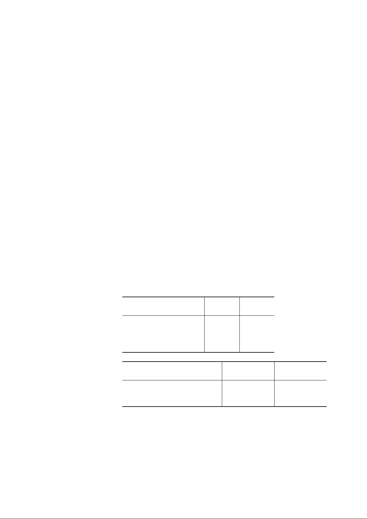
Three types of print quality are available — letter, correspondence, and draft. Letter quality has the highest
resolution. Draft quality has the lowest resolution but is easy to read and has the highest speed. Each print
quality can be made thicker in multicopy mode which can be easily set from the control panel or by DLMENU.
Choose the quality to suit the application.
Quality
Letter
Correspondence
Draft
dpi: Dots per inch
cps: Characters per second
Paper type
Continuous forms or cut sheets
Continuous forms
Cut sheets
Resolution (dpi: h × v)
360 × 180
180 × 180
120 × 180
Paper path
Fed from the front
Fed from the rear
Fed from the CSF
Normal mode
5 copies
5 copies
5 copies
Speed (cps at 10 cpi)
100
200
360
Multicopy mode
8 copies
6 copies
5 copies
Number of copies includes the original.
1-1
Page 12
1.2 Print Modes
Multiple print modes enable word processing with great flexibility.
The DL9300/9400 has the following print modes and line spacing:
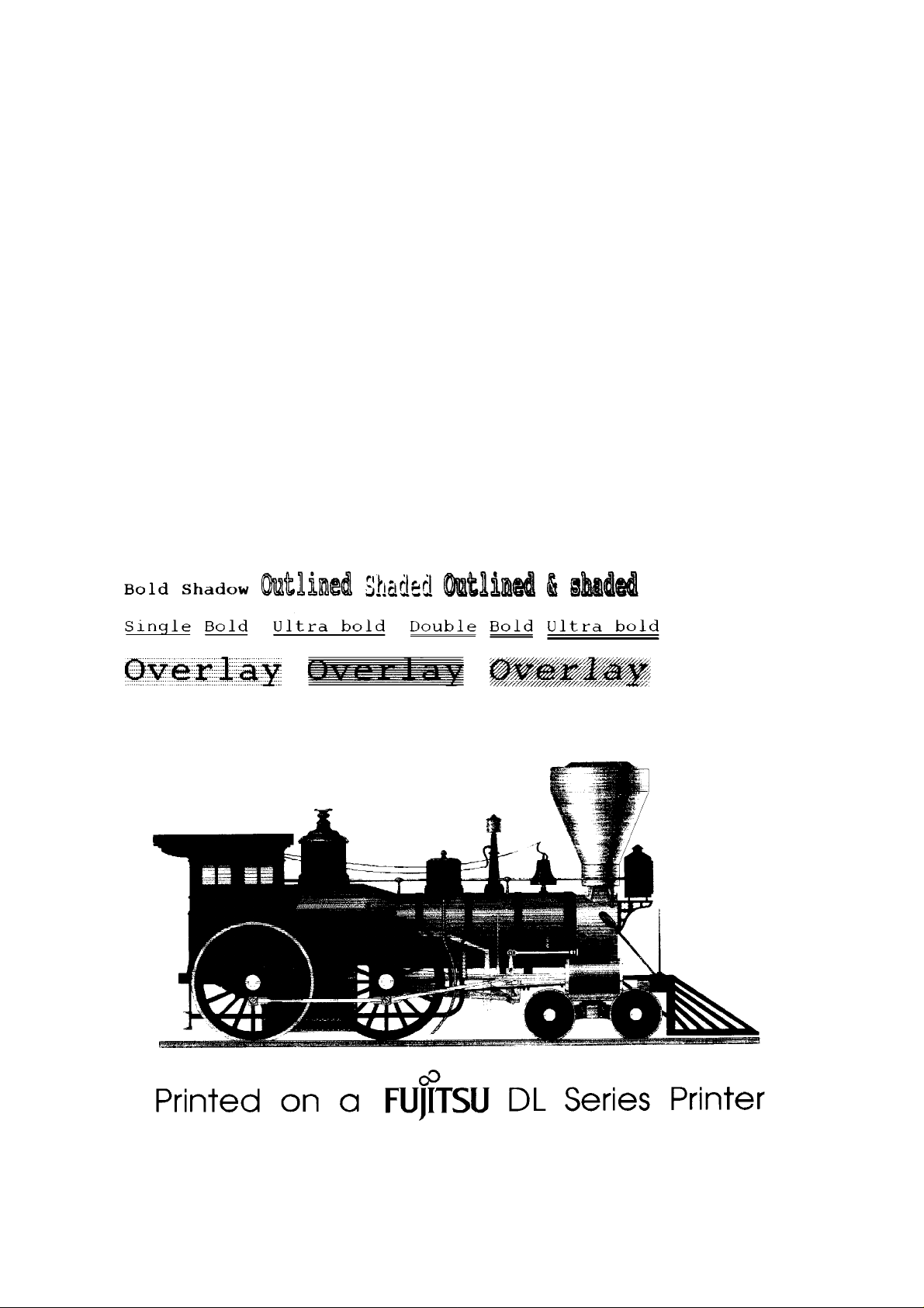
Print modes: Bold, shadow, double-width, double-height, condensed, superscript, subscript,
underline, justified, and proportional. Other modes, such as italic, multisize, outline,
shaded, and overlay are available depending on the emulation used.
Line spacing: 1, 2, 3, 4, 5, 6, 7, or 8 lines per inch
Programmable in 1/360 inch and other increments for image graphics
Both 8-bit and 24-bit graphics are available. The dot density is up to 1/360 × 1/360 inch.
Figure 1.1 shows printing samples.
1-2
Figure 1.1 Printing samples
Page 13

1.3 Fonts and Character Sets
The DL9300/9400 has 18 resident fonts which are supported by a maximum of 58 national character sets. See
Appendix B for printing samples of resident fonts.
The following 15 resident fonts are letter-quality:
Bit map fonts: Courier 10, Pica 10, OCR-A 10, OCR-B 10, Prestige Elite 12, and Boldface PS
Scalable fonts: Courier (upright, italic, and bold)
Nimbus Sans
Timeless (upright, italic, and bold)
*1 Nimbus Sans is a registered trademark of URW Unternehmensberatung Karow Rubow
Weber GmbH, Hamburg.
The following three resident fonts are used for speed or condensed printing:
Correspondence, Draft, and Compressed
For downloadable fonts, up to 96K bytes of user-designed fonts can be downloaded to RAM.
(*1)
(upright, italic, and bold)
The DL9300/9400 has 56 or 58 national character sets (depending on the emulation) besides the basic character
sets. This makes the printer be adaptable to various languages. Note that some character sets cannot be used
with some fonts. See Appendix A for details.
1.4 Emulations and Compatibility with IBM PC Printers
The DL9300/9400 has two emulations in addition to the Fujitsu DPL24C PLUS command set. These are all
resident in ROM:
Fujitsu DPL24C PLUS, including bar code commands
IBM Proprinter XL24E emulation
Epson ESC/P2 emulation
The user can run many software applications without changing computer or application software, just by selecting an emulation using the printer control panel or the DLMENU.
When the IBM Proprinter XL24E emulation is selected, the command set and aspect ratio of the graphics are
exactly the same as the IBM Proprinter when alternate graphics mode (AGM) is selected from the printer control
panel in setup mode.
Many 24-wire printers produce graphics having a different aspect ratio than other manufacturers' printers
because of different spacing of the print head wires. The DL9300/9400 produces the same aspect ratio as IBM
PC printers, including 9-wire printers. This offers the advantage of full compatibility with graphics software for
IBM printers.
1-3
Page 14
1.5 Printing Speed and Throughput
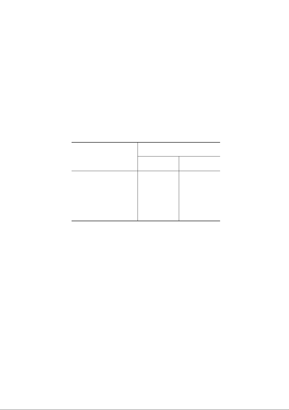
The DL9300/9400 prints text at the following speeds:
Quality
Letter
Correspondence
Draft
cpi: Characters per inch
cps: Characters per second
The DL9300/9400’s buffer control enables data reception while other data is being printed. Other features, such
as logical seek, bidirectional printing, and horizontal and vertical tabulation also improve printer throughput.
The printer throughput, based on ECMA 132 (letter test pattern), is listed in the following table:
Quality
Letter
Draft
Speed at 12 cpi
120 cps
240 cps
432 cps
DL9300
156 pages/h
320 pages/h
Speed at 10 cpi
100 cps
200 cps
360 cps
DL9400
156 pages/h
320 pages/h
1.6 Automatic Paper Loading, Switching, and Tearing-Off
Paper handling is automated as follows:
Paper is loaded or unloaded automatically using the LOAD button on the control panel. The print position can
be adjusted for each paper type and path beforehand in setup mode.
Cut sheets can be used without removing continuous forms currently loaded. Pressing the LOAD button moves
the loaded continuous forms from the platen to the parking position (forms tractor). After pressing the PAPER
PATH button so as to turn on the CUT SHEET indicator, pressing the LOAD button loads a cut sheet up to the
platen. After the cut sheet is printed, pressing the PAPER PATH button so as to turn on the FRONT TRACTOR
or REAR TRACTOR indicator and pressing the LOAD button reloads the continuous forms from the parking
position.
There is no waste of paper in tearing off the continuous forms printed. Pressing the TEAR OFF button on the
control panel positions the bottom perforation of the last printed page at the tear-off edge provided at the front
cover or upper cover of the printer. After tearing off the last page, pressing any button backs the new first page
to the print position. This back-and-forth feeding is called tear-off feeding. Tear-off feeding saves pages.
Automatic tear-off feeding can be specified in setup mode; the printer waits for a while between jobs instead of
requiring the TEAR OFF button to be pressed. If a job ends and no data is sent from the computer, the printer
automatically feeds the last page to the tear-off edge.
1-4
Page 15
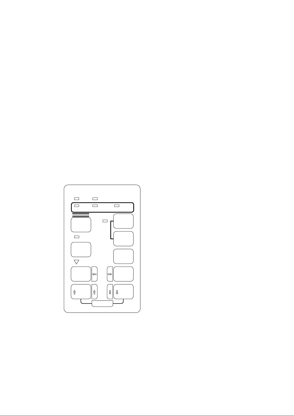
1.7 Control Panel
The control panel has nine push-button switches, eight LED indicators, and a buzzer. Indication of functions and
statuses are easy to understand.
The control panel operates in two modes: normal and setup.
• Normal mode is used in daily operation such as paper path selection, paper loading and unloading, forms feed,
and line feed. It also enables copy control, tear-off feed, and top-of-form adjustment.
• Setup mode is used in customizing the printer to the user environment when first connecting the printer to the
computer or when printing special documents. It is also set using the DLMENU. Setup mode enables the
user to select printer features such as font settings, line and character spacing, page margins, serial interface
parameters, and other infrequently used functions.
See Chapter 4 for details.
POWER PAPER OUT
FRONT
TRACTOR
PAPER PATH
MULTI
MULTI
COPY
FRONT
FRONT DIR
MICRO
SAVE TOP
SET UP
REAR
TRACTOR
CUT
SHEET
ONLINE
LOAD
LF / FF
TEAR OFF
MICRO
Figure 1.2 Control panel
1-5
Page 16
1.8 Multiple Paper Paths and Switching (HCPP)
The DL9300/9400 has a wide variety of paper feed paths for both continuous forms and cut sheets. These paths
are almost straight so that the printer can use various types of paper and be adapted to various user environments.
The DL9300/9400 uses a friction feed platen, a standard tractor unit, and an optional tractor unit as the paper
feed mechanism for continuous forms. The optional tractor unit is exactly the same with the standard one. The
tractor unit is removable and installable at the front or rear of the printer. It pushes continuous forms toward the
platen. When the printer is shipped, the tractor unit is installed at the front of the printer.
The 9300/9400 uses a mechanism that switches these three paper paths by a command. This is called hostcontrolled paper path (HCPP) mechanism. The HCPP mechanism switches power transmission to the tractors.
Three states are possible: front tractor selected, rear tractor selected, and cut sheet selected. Switching is
possible through software or by the control panel. The paper on the platen is unloaded to the park position or
ejected, and then the paper feed path is switched. When switching from a cut sheet to continuous forms, the
continuous forms are automatically loaded to the print position.
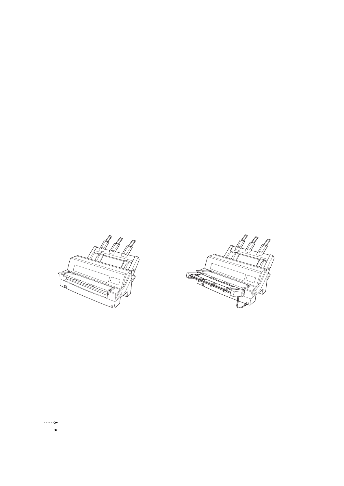
As the cut-sheet feed mechanism, the DL9300/9400 uses the platen and an optional single-bin cut-sheet feeder
which is also installable at the front or rear of the printer. The SF930 is available for the DL9300, and the SF940
for the DL9400.
SF940 mounted at rear of printer SF940s mounted at both front and rear of printer
Figure 1.3 Cut-sheet feeders
Two tractor units can be used at the same time. Two cut-sheet feeders can be used at the same time. However,
at the front of the printer, the tractor unit cannot be used with the cut sheet feeder at the same time.
The 9300/9400 has eight paper feed paths depending on combinations of feed mechanisms. Figure 1.4 shows
these paper paths. At the right side of each illustration are listed available paper feed paths.
Legend:
: Cut sheet
: Continuous forms
(n) : Input
[n] : Output
1-6
Page 17
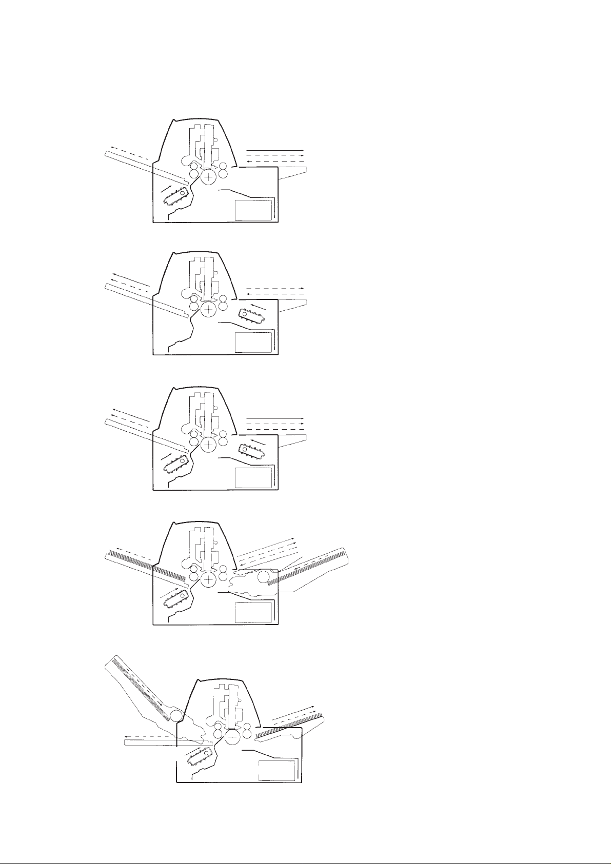
a. Rear tractor
[2]
(3)
b. Front tractor
[4]
[2]
c. Front and rear tractors
(4)
[3]
[1]
[1]
(1) (2)
(1) (2)
(1) Paper table → Print → Paper table
(2) Paper table → Print → Rear stacker
(3) Rear tractor → Print → Front eject
(1) Paper table → Print → Paper table
(2) Paper table → Print → Rear stacker
(4) Front tractor → Print → Rear eject
[4]
[2]
(3)
(4)
d. Rear tractor and front cut sheet feeder
[6]
(3)
e. Rear tractor and rear cut sheet feeder
(7) (8)
[3]
[3]
[1]
(1)
[3]
[1]
(1) (2)
[5]
[7]
(5) (6)
(1) Paper table → Print → Paper table
(2) Paper table → Print → Rear stacker
(3) Rear tractor → Print → Front eject
(4) Front tractor → Print → Rear eject
(1) Paper table → Print → Paper table
(3) Rear tractor → Print → Front eject
(5) Front cut sheet feeder → Print → Paper table
(6) Front cut sheet feeder → Print → Rear stacker
(3) Rear tractor → Print → Front eject
(7) Rear cut sheet feeder → Print → Paper table
(8) Rear cut sheet feeder → Print → Rear stacker
[8]
(3)
Figure 1.4 Multiple paper paths (to be continued)
1-7
Page 18

f. Rear tractor and front and rear cut sheet feeders
(7) (8)
[2] [6] [8]
(3)
[3]
[1] [5] [7]
(1) (2)
(5) (6)
(1) Paper table → Print → Paper table
(2) Paper table → Print → Rear stacker
(3) Rear tractor → Print → Front eject
(5) Front cut sheet feeder → Print → Paper table
(6) Front cut sheet feeder → Print → Rear stacker
(7) Rear cut sheet feeder → Print → Paper table
(8) Rear cut sheet feeder → Print → Rear stacker
Figure 1.4 Multiple paper paths (continued)
1.9 Automatic Print Head Gap Adjustment (APTC)
The 9300/9400 automatically adjusts the gap between the print head and the platen for paper thickness when
paper is loaded. This function is usually called APTC (abbreviated from automatic paper thickness control). It
is useful for users who often change paper types.
The print head carriage has a pressure sensor on the card guide which faces the platen. When paper is loaded,
the card guide is first set to the widest gap, pressed against the platen over the paper, and then backed for the
proper gap. The gap can be also adjusted by the paper thickness indicator in manual mode (the indicator is
accessible at the left of the printer when the front cover is open).
1.10 Automatic Interface Switching
The 9300/9400 has two interfaces: Centronics parallel and RS-232C serial. The dual interface allows the user to
connect the printer to both a network environment and a PC environment at the same time. The printer will
automatically switch to the proper interface (parallel or serial) when an AUTO option is selected for the
<INTRFCE> item by the HARDWRE function in setup mode.
1.11 Printer Driver and DLMENU
The 9300/9400 is delivered with two floppy disks.
One floppy disk contains printer drivers for Windows 3.x and Windows 95. The printer driver is a control
program to be installed on the computer for controlling document printing on the user printer. This printer driver
allows the application programs to make the best use of the DL9300/9400's functions. The printer driver for
Windows 95 has the plug and play detection capability.
The other floppy disk contains the DLMENU. The DLMENU is a printer remote setup utility program which
controls printer features in setup mode from the computer display in place of the printer control panel. This
greatly releases the user from tedious operation of setting up the printer from the control panel.
1-8
Page 19

CHAPTER 2 MODEL CONFIGURATION AND
EQUIPMENT STRUCTURE
This chapter gives the model configuration and equipment structure.
2.1 Model Configuration
The printer model differs with two specifications: print line and power supply.
DL9300/9400
Basic specification
Print line at 10 cpi: 80 columns (DL9300)
136 columns (DL9400)
Alternative specification
Power supply: 100-120 VAC or 220-240 VAC input
Add-on installable at factory
Front cover (transparent type)
Add-ons installable by user
Cut-sheet feeder
Tractor unit
cpi: characters per inch
Notes:
The following three emulations are standard for all versions.
• DPL24C PLUS: Fujitsu proprietary command set for DL-series serial printers
• IBM Proprinter XL24E
• Epson ESC/P2
The following two interfaces are standard and automatically switched for all versions (dual interface).
• Centronics parallel
• RS-232C serial
The printer is shipped with the standard tractor unit installed at the front of the printer.
This manual covers all models. An understanding of equipment structure helps relate the information in this
chapter to a particular model.
2-1
Page 20
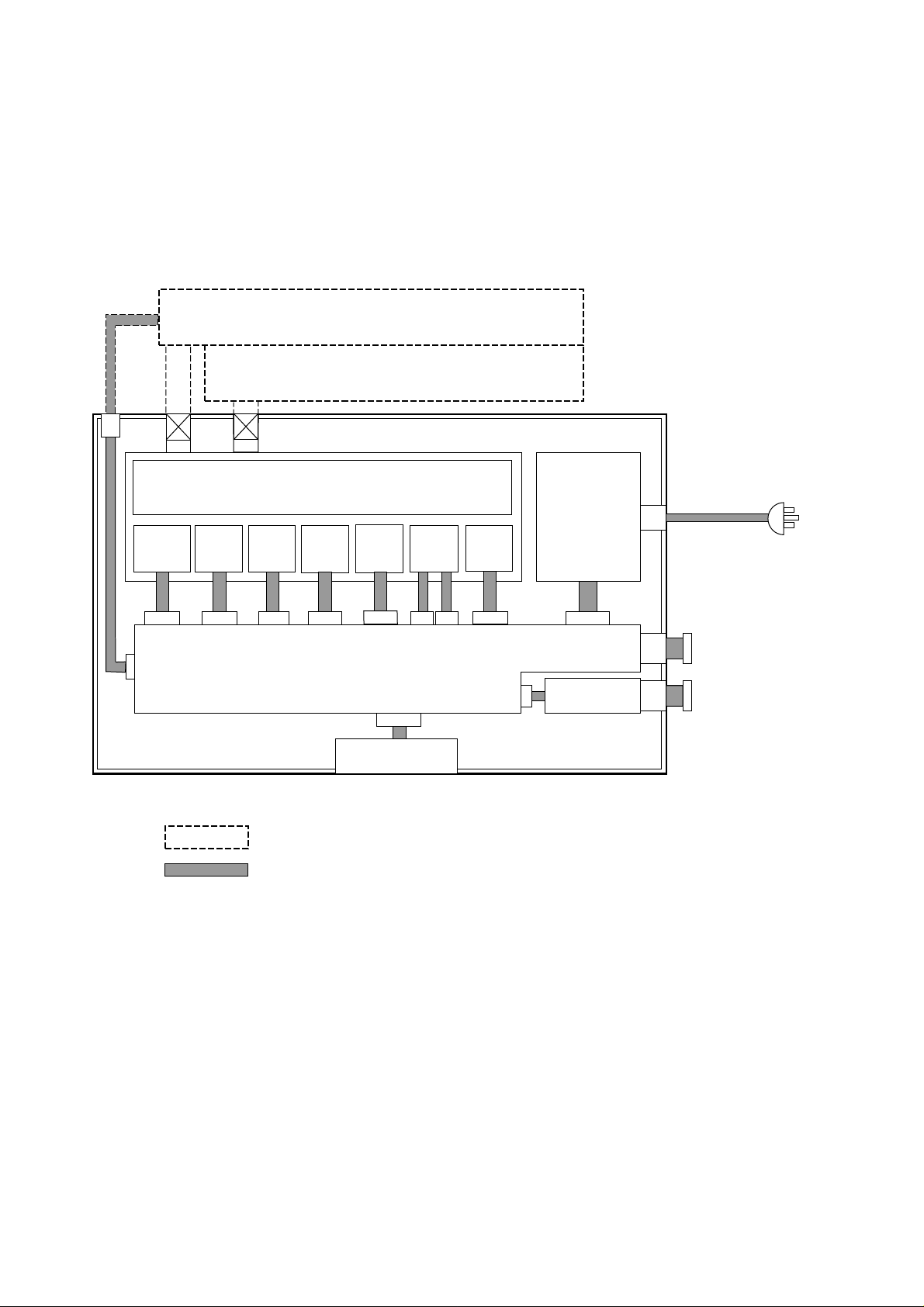
2.2 Block Diagram
Figure 2.1 is a block diagram of the DL9300/9400 printer.
Cut-sheet feeder
Additional tractor unit
Printer
Sensors
Note:
Gears
Standard tractor unit and platen
LF
motorTRmotor
APTC
motor
Printer control board
Option
Cable
Printing mechanism
HCPP
motor
Control panel
Print
head
100-120 VAC or
220-240 VAC
Power supply
SP
motor
Centronics
To computer
RS-232C
(1) Printing mechanism
The DL9300/9400 printing mechanism consists of a print head and carriage, a carriage drive mechanism, a
paper feed mechanism, a paper path selection mechanism, an automatic print head gap adjustment mechanism, and sensors. The carriage includes a ribbon feed mechanism and the other sensors.
The printing mechanism uses five motors for driving the mechanism components so as to distribute the load.
The five motors each correspond to the platen, the tractor unit, the APTC mechanism, the HCPP mechanism,
and the print head carriage.
2-2
Figure 2.1 Printer block diagram
Page 21

(2) Printer control board
The printer control board consists of a main controller, memory, sensor receivers, drivers, a Centronics
parallel interface controller, and an RS-232C serial interface controller. This board governs the computer
interface, control panel, and printing mechanism using the main controller and memory that holds resident
character patterns and firmware including resident emulation programs.
(3) Control panel
The control panel is used by the user for operations such as changing or feeding paper, resetting the printer,
and selecting printer features in setup mode. The control panel indicates the printer status using a buzzer
and LED indicators.
(4) Power supply
The power supply provides power for operating the printer. Its specifications depend on the input AC
voltage.
(5) Cut-sheet feeder (user option)
The cut-sheet feeder is driven by a gear on the platen shaft. It has a cable to be connected to the printer for
controlling the feed rollers in the cut-sheet feeder. The feeder enables cut sheets to be fed and printed
continuously.
(6) Tractor unit (user option)
A second tractor unit can be installed if the user requires dual tractor feeding capability.
2-3
Page 22

2.3 Structure
DL9300/9400 printer
Upper cover assembly
Front cover assembly
Paper table assembly
Rear stacker assembly
Tractor unit
Printer unit
ROM board [control board with ROM]
RS-232C board
Power supply (100-120 or 220-240 VAC)
OP board [control panel]
Printer lower unit Bottom cover
Printer mechanism assembly
AC inlet assembly
Front CSF board
Frame assembly Upper stay assembly
Front stay assembly FPSS PCA (front paper set or
Rear stay assembly RTRPE unit (rear tractor paper end)
Platen roll assembly
DV roller unit
Nip roller assembly
LF motor assembly
TR motor assembly
SW subassembly
HCPP motor assembly
Carrier unit [carriage unit]
Card guide assembly
Ribbon feed assembly
Timing belt
SP motor unit
APTC unit APTC motor unit
Print head (consumables)
Ribbon cartridge (black, consumables)
front tractor paper end sensor)
2-4
Notes:
[ ] indicates a general name of the component or the subassembled component referred frequently
in this manual or the user's manual.
( ) shows options that determine the specification of the component.
Page 23
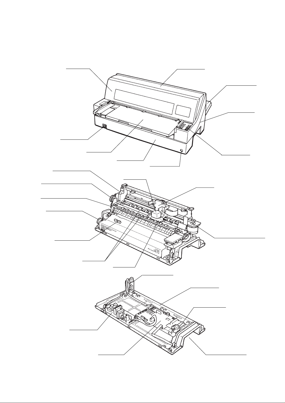
Figure 2.2 shows printer components of the DL9400. (DL9300 is the same except for width.)
Upper coverFront cover
Power switch
Rear stacker
Upper cover
APTC mechanism
Paper thickness indicator
Paper feed mechanism
HCPP mechanism
Paper end sensor
(Front tractor)
Nip rollers
Paper table
Control panel
Upper cover
CSF connector
Print head
Carriage
Print head
Ribbon feed mechanism
Sensors
Carriage drive mechanism
Card guide
AC inlet and
CSF connector
Bottom cover
Power supply
Figure 2.2 Printer components (DL9400 printer)
ROM board
RS-232C board
Interface connectors
2-5
Page 24

2.3.1 Exterior components
This section gives information on exterior components of the printer: covers, removable mechanism units, etc.
The upper cover is fastened with screws at the back (two for the DL9300 and three for the DL9400).
(1) Upper cover
The interface cable connector is on the right side of the printer, as seen from the front of the upper cover, so
the interface cable does not interfere with the paper feed path.
(2) Front cover
The front cover is opened to replace the ribbon cartridge.
(3) Paper table
The paper table guides a cut sheet manually fed by the user. It can also stack printed cut sheets when it is set
at the "down" position.
(4) Rear stacker
The rear stacker holds printed cut sheets. It must be set at the "down" position when an optional cut-sheet
feeder is installed at the back of the printer.
(5) Control panel
The control panel consists of an LSI, nine push-button switches, eight LEDs, and a buzzer. The switches are
used for operations such as loading and feeding paper and controlling printing pressure. Some switches are
also used in setup mode in place of the DLMENU. The LEDs indicate printer basic statuses and paper feed
path conditions. The buzzer sounds to indicate certain operating and printer statuses.
2.3.2 Printing mechanism
The two screws secure the printing mechanism to the bottom cover. The two hooks on the bottom cover hold the
mechanism in position.
(1) Carriage
The carriage supports the print head and ribbon cartridge, and slides left and right on the stay shaft. The
ribbon feed gear system moves the ribbon in one direction regardless of carriage movement. It has three
sensors: LRES, TOF, and APTC. The LRES detects both left and right ends of the carriage movement. The
TOF detects the top edge of paper. The APTC detects the gap between the print head and the platen.
(2) Carriage drive mechanism
The stay shaft and the stay guide support the carriage; the stepping motor and timing belt move the carriage
horizontally.
(3) Paper feed mechanism
The stepping motor drives the platen and/or tractors through gears to feed paper. See also the HCPP mechanism.
2-6
Page 25

(4) Host-controlled paper path (HCPP) mechanism
The HCPP mechanism switches power transmission to the tractors. Three states are possible: front tractor
selected, rear tractor selected, and cut sheet selected. Switching is possible through software or by the
control panel. The paper on the platen is unloaded to the park position or ejected, and then the paper feed
path is switched. When switching from a cut sheet to continuous forms, the continuous forms are automatically loaded to the print position.
(5) Paper sensors
There are six paper sensors for controlling paper feeding:
Function Paper sensed Sensor type
Front paper set Cut sheet, continuous forms, and CSF Lever and transparent type photo-interrupter
Top-of-form Cut sheet, continuous forms, and CSF Reflective type photointerrupter
End of paper Continuous forms on the rear tractor Lever and transparent type photointerrupter
End of paper Continuous forms on the front tractor Lever and transparent type photointerrupter
Paper empty Cut sheets in the front CSF Microswitch
Paper empty Cut sheets in the rear CSF Microswitch
(6) Automatic paper thickness control (APTC) mechanism
The APTC mechanism adjusts the gap between the print head and the platen. When paper is loaded, the
print head is pressed against the platen and the sensor issues a signal when the print head is stopped by the
paper. The print head is then returned by a certain distance so that the gap (actually between the print head
and the paper) is properly adjusted regardless of the paper thickness.
2.3.3 Bottom cover
(1) Bottom cover
The bottom cover supports the printer mechanism.
(2) ROM board (control board with ROM)
The ROM board controls the host interface, control panel, and printing mechanism using an MPU and an
LSI circuit. Memory holds the resident character patterns and firmware, including resident emulation
programs. This board also has drivers and receivers for other components. The separate RS-232C serial
board is connected to this board through the cable.
(3) Power supply
The power supply outputs a constant voltage, regardless of the input AC line voltage, within ranges of 100 to
120 VAC or 220 to 240 VAC. The power supply is at the front of the printer and includes an AC line switch
and noise filter.
2-7
Page 26

(4) AC inlet and CSF connector (rear CSF)
The AC inlet consists of the power input connector, the wiring cable, and the bracket on which the connector
for the rear CSF is mounted.
(5) CSF connector (front CSF)
The connector board for the front CSF is mounted at the front right of the bottom cover.
2.3.4 Options and consumables
(1) Cut-sheet feeders
A cut-sheet feeder allows both single-part cut sheets and multi-part cut sheets to be fed automatically.
The SF930 single-bin feeder is available for DL9300, and the SF940 single-bin feeder for DL9400.
(2) Tractor unit
An additional tractor unit can be installed in the printer. Because the standard tractor unit is installed at the
front of the printer at shipment, the additional tractor is installed at the rear of the printer. However, both
tractor units are the same, and installable at either position.
(3) Front cover (transparent type)
This type of front cover has the transparent window so that printed characters are visible without opening the
cover.
(4) Ribbon cartridge
The black ribbon cartridge contains a continuous inked ribbon and is installed on the print head carriage.
(5) Print head
The 24-wire print head is easily installed on and removed from the print head carriage.
2-8
Page 27
CHAPTER 3 SPECIFICATIONS
This chapter details DL9300/9400 specifications.
3.1 General Specifications
3.1.1 Print head and carriage
Printing method: 24-wire dot matrix
Wire diameter: 0.2 mm (0.008 in.)
Wire spacing (vertical): 0.141 mm (1/180 in.)
Printing direction: Bidirectional, logic-seeking or unidirectional seeking
Character cell: Letter quality 36 × 24 (10 cpi)
(horiz × vert) 30 × 24 (12 cpi)
Correspondence quality 18 × 24
Draft quality 12 × 24
Printing speed: Print quality 10 cpi 12 cpi
Letter quality 100 cps 120 cps
Correspondence quality 200 cps 240 cps
Draft quality 360 cps 432 cps
Throughput: Print quality DL9300 DL9400
(ECMA 132,
letter test pattern) Letter quality (continuous forms) 156 pages/h 156 pages/h
Draft quality (continuous forms) 320 pages/h 320 pages/h
3-1
Page 28
Resolution: Letter quality 360 × 180 dots/inch
(horiz × vert) Correspondence quality 180 × 180 dots/inch
Draft quality 120 × 180 dots/inch
Graphics 360 × 360, 360 × 180, 180 × 180,
120 × 180, 90 × 180, 60 × 180 dots/inch
240 × 72, 120 × 72, 60 × 72 dots/inch
200 × 60, 100 × 60, 90 × 60,
200/3 × 60, 60 × 60, 50 × 60 dots/inch
Character spacing: 2.5, 3, 5, 6, 10, 12, 15, 17.1, 18, and 20 cpi and proportional spacing
Programmable in 1/360-inch and other increments for image graphics
Character expansion: Double or quadruple width and height (control panel or DLMENU)
Multiwidth and height (DPL24C PLUS printer command)
Characters per line:
Characters per inch (cpi)
(Character spacing)
10 80 136
12 96 163
15 120 204
17.1 136 232
18 144 244
20 160 272
3.1.2 Forms feed
Feeding: Continuous forms:
Standard tractor unit installed at front of printer at shipment, but installable at rear of printer
Optional tractor unit installable at rear or front of printer
Cut sheets:
Friction-feed platen (standard)
Cut-sheet feeder (option) installable at rear and front of printer
Note that front and rear tractor units or front and rear cut-sheet feeders can be used at the
same time. However, the front tractor unit cannot be installed with the front cut-sheet
feeder at the same time.
Characters per line (cpl)
DL9300 DL9400
Feed direction: Bidirectional (push-feed tractor)
Line spacing: 1, 2, 3, 4, 5, 6, 7, and 8 lines per inch
Programmable in 1/360-inch and other increments for image graphics
Line feed speed: Less than 60 ms/line (at 6 lines per inch)
Forms feed speed: 6 inches per second
Paper detection: 6 sensors: front paper set, top-of-form, end of paper (front and rear tractors), paper empty
(front and rear CSFs)
3-2
Page 29

3.1.3 Character sets and fonts
Character sets: DPL24C+/XL24E IBM PC character sets 1 and 2
IBM PS/2 character sets (code pages) and other
national character sets (56 languages
in total)
Fujitsu character set (692 characters)
ESC/P2 Italic character set
Graphics character sets 1 and 2
IBM PS/2 character sets (code pages) and other
national character sets (58 languages
in total)
National character sets: USA (=code page 437), United Kingdom,
(All emulations) German, Swedish, ISO 8859-1, ECMA 94,
Code pages 437, 850, 852, 855, 860, 863, 865,
and 866,
Hungarian, Slovenian, Polish, Mazowian, Latin 2,
Kamenicky, Turkish, Cyrillic, IBM 437, IBM
851,
ELOT 928, Latin Polish, ISO Latin, Lithuanian 1,
Lithuanian 2, MIK, Macedonian, ABG, ABY,
Code page MAC, ELOT 927, DEC Greek, Greek
11,
Code page 862, Hebrew Old, and Hebrew DEC
Note:
Some national character sets do not support
some
resident fonts. See Appendix A for details.
Resident fonts: Letter quality
Bit map fonts 6 fonts
Courier 10, Pica 10, Prestige Elite 12, Boldface PS,
OCR-B 10, and OCR-A 10
Scalable fonts 9 fonts
Courier (upright, italic, bold)
Nimbus Sans (upright, italic, bold)
Timeless (upright, italic, bold)
Correspondence (*1) 1 font
*1 The correspondence font has the same print quality but higher printing speed
compared to letter quality fonts.
Draft quality 1 font
Compressed 1 font
Note:
Italic, shadow, bold, outlined, screened, enlarged, and super/subscript can be specified
by commands.
Downloadable RAM: 0, 64K, 72K, 88K, 94K, 95.75K, or 96K bytes
3-3
Page 30
3.1.4 Forms
Width: Forms type DL9300 DL9400
Continuous forms
Cut sheets (sheet feeder)
Cut sheets (paper table)
Length: Forms type DL9300 DL9400
Continuous forms 102 mm (4 in.) or more 102 mm (4 in.) or more
Cut sheets (sheet feeder)
Cut sheets (paper table)
Thickness: Up to 0.65 mm (0.025 in.)
Thickness control: Automatic print head gap control (manual control possible)
Loading: Autoloading for continuous forms and cut sheets
Parking: Cut sheets are loaded without removing continuous forms from the printer;
continuous forms are unloaded to the parking position and stand by for the next
loading.
102 to 267 mm (4 to 10.5 in.) 102 to 420 mm (4 to 16.5 in.)
102 to 257 mm (4 to 10.1 in.) 102 to 420 mm (4 to 16.5 in.)
55 to 267 mm (2.2 to 10.5 in.) 55 to 420 mm (2.2 to 16.5 in.)
70 to 364 mm (2.8 to 14.3 in.) 70 to 420 mm (2.8 to 16.5 in.)
70 to 364 mm (2.8 to 14.3 in.) 70 to 420 mm (2.8 to 16.5 in.)
Cut-sheet feeder (option): DL9300 DL9400
SF930 SF940
Forms cutting: 25.4-mm (1-in.) margin tear-off
Paper detection: Left and right edges of paper
Top and bottom edges of paper
Feed path: Nearly flat
See Section 3.7 for details on forms specifications.
3-4
Page 31

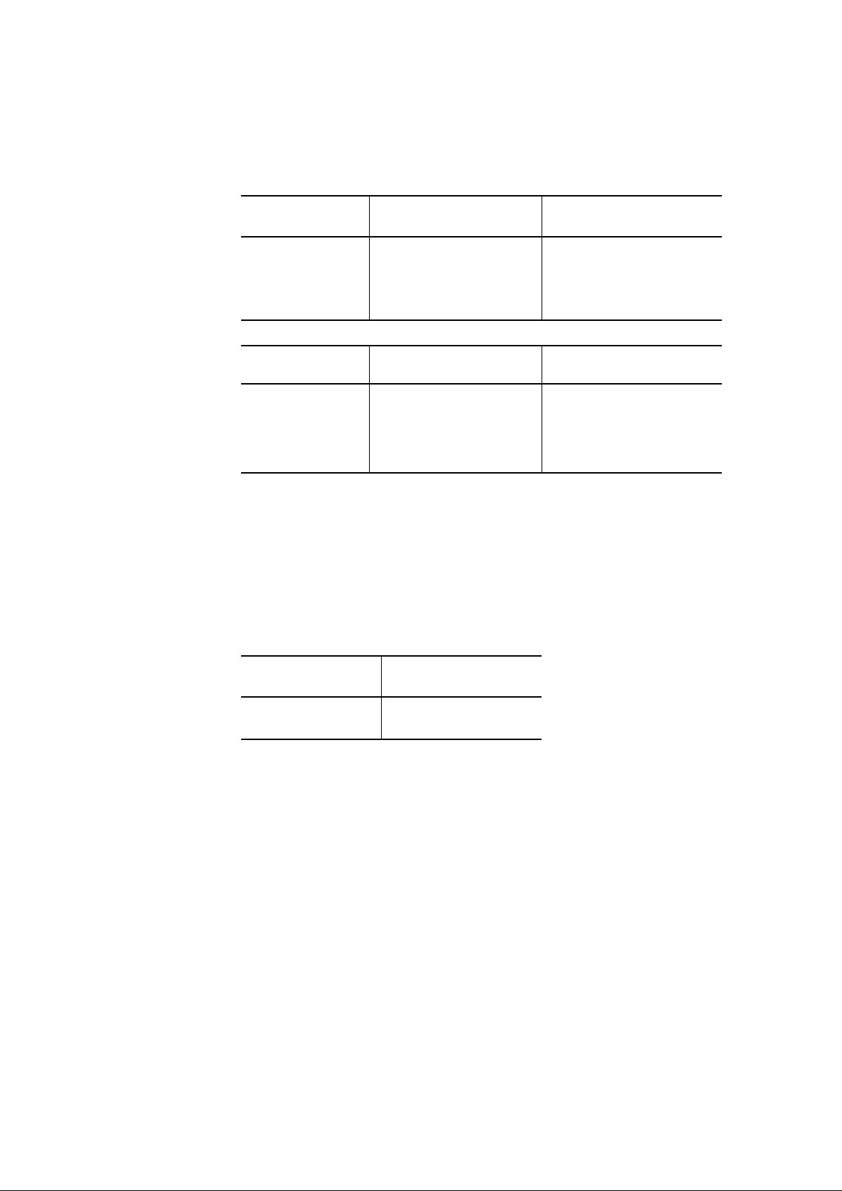
3.1.5 Other printing features
Multiple copies: Original + 4 copies (depending on paper) in normal mode
Original + 7 copies (depending on paper) in multicopy mode
3.1.6 Acoustic noise
Average: 55 dB (A)
Measurement conditions: ECMA-74 Section IV, ISO 7779, bystander position-front
Printing conditions: 60 g/m2 thick, 13 inches wide, continuous paper, and letter quality printing
3.1.7 Interfaces
Types: Centronics parallel + RS-232C serial
Parallel: Bi-directional, complying with the IEEE 1284 standard
RS-232C: 150, 300, 600, 1200, 2400, 4800, 9600, and 19200 baud
X-ON/X-OFF (DC1/DC3), DTR, and RC protocols. The ETX/ACK protocol is not
applicable to IBM character set 2.
Input buffer: 0, 256, 2K, 8K, 24K, 32K or 96K bytes
3.1.8 Emulations
Resident: Fujitsu DPL24C PLUS
IBM Proprinter XL24E
Epson ESC/P2
3.1.9 Control panel
Switches: Nine push-button switches: ONLINE, PAPER PATH, FRONT DIR, LOAD, LF/FF,
TEAR OFF, MULTI COPY, ⇑MICRO, and ⇓MICRO
Indicators: Three LEDs for basic status: POWER, PAPER OUT, and ONLINE
Five LEDs indicating the currently selected paper path and multicopy mode
See Chapter 4 for details.
3-5
Page 32

3.2 Electrical Conditions
Input voltage: 100 to 120 VAC ±10% (100 V models)
220 to 240 VAC –10%, +6% (200 V models)
Frequency: 50 or 60 Hz +2%, –4%
Insulation resistance: AC-FG 10 MΩ or more
Dielectric strength: AC-FG 1 min. at 1.25 kVAC (100 V models)
1 min. at 1.5 kVAC (200 V models)
Power consumption:
(average)
Condition
Operating
Standby
Input voltage
100–120
60 W
15 W
220–240
70 W
15 W
3.3 Environmental Conditions
Temperature: Operating 5 to 38°C (41 to 100°F)
Storage –15 to 60°C (–4 to 140°F)
In transit –25 to 60°C (–13 to 140°F)
Gradient 15°C/h or less
Note:
Print quality is guaranteed from 10 to 30°C.
Humidity: Operating 30 to 80% RH
Storage 10 to 95% RH (no condensation)
Gradient 30% RH/day or less
Maximum wet bulb 29°C (84°F)
Note:
Print quality is guaranteed from 30 to 70% RH.
Remarks
Printing letter quality H
Vibration: Operating 0.2 G. The printer is not damaged, but printing quality is not
guaranteed.
Storage 0.5 G
Packaged 1.25 G (5 to 55 Hz, vertical; 2 min./cycle, 10 min.)
0.75 G (5 to 55 Hz, horizontal; 2 min./cycle, 10 min.)
Shock: Operating 3 G. The printer is not damaged, but printing quality is not
guaranteed.
Storage 10 G
Packaged Withstanding a 60 cm (23.6 in.) drop test
3-6
Page 33

Tilt: Operating 5° (left and right)
7° (back and front)
Electrostatic strength: 9 kV minimum, no errors during test printing under the following conditions:
Contact cycle and period: 10 Hz and 3 min.
Capacitor-resistor circuit: 150 pF and 150 Ω
Safety: Model Regulation Region
100-120 VAC UL 1950-D3 United States
CSA C22.2/950 Canada
220-240 VAC TÜV EN 60 950 Germany
RFI regulation: Model Regulation Region
100-120 VAC Class B, FCC Part 15B United States
3.4 Physical Specifications
Dimensions: DL9300 DL9400
Width 456 mm (17.9 in.) 598 mm (23.5 in.)
Depth (*) 300 mm (11.8 in.) 300 mm (11.8 in.)
Height 250 mm (9.8 in.) 250 mm (9.8 in.)
* Excluding the paper table and the rear stacker
Weight: DL9300 DL9400
12 kg (26.4 lb) 14 kg (30.8 lb)
3-7
Page 34

3.5 Reliability
MTBF: 8,000 hours using a 25% duty cycle, 25% page density, and three hours of power-on
operation per day.
MTTR: 0.5 hours
Printer service life: 5 million lines or 5 years
Consumables Print head 300 million strokes for each wire (90% confidence level)
This corresponds to about 110 million characters for draft quality or 70
million characters for letter quality.
Ribbon 5.0 million characters for draft quality (black ribbon cartridge)
3.6 Protection and Restrictions
3.6.1 Protection
To protect the print head, controller, and power supply, the printer checks for the following conditions:
• High temperature of the print head
• Damage to the carriage motor driver and the line feed motor driver or a short circuit in the motors
• Overvoltage of +34 V
To ensure printing quality, the 24 dot wires of the print head are divided into three groups and 3-pass
unidirectional printing is done when one of the following overload conditions is detected:
• +34 V power falls below the predetermined voltage.
• The print head’s thermal sensor detects a high temperature.
• Image data has a dot density higher than the prescribed printing duty.
Note:
No overload condition occurs when the printing load is smaller than printing 66 lines at 33% duty.
3-8
Page 35

3.6.2 Restrictions
To avoid damaging the printer, do not:
• Feed lines continuously more than 3 minutes.
• Continue character spacing without printing more than 5 minutes.
• Continuously print lines of 5 characters or less (at 10 cpi) more than 5 minutes.
• Continuously print at 50% duty more than 1 minute.
Note:
If the above limits are exceeded, the printer’s service life may be greatly shortened.
3-9
Page 36

3.7 Details on Forms Specification
The DL9300/9400 processes a variety of forms: letter paper, typewriter paper, copy paper, business stock forms,
labels, and ordinary envelopes. This section gives general specifications for continuous forms and cut sheets.
Before using paper, check that it satisfies the requirements below. For nonstandard forms such as envelopes and
labels, paper of nonstandard size or thickness, or cut sheets for autofeeding using cut-sheet feeders, consult your
Fujitsu representative.
3.7.1 Size and thickness
Table 3.1 Forms size and thickness
Item
Width
Length
Thickness (*1)
Requirements
DL9300 DL9400
Cut sheets (paper table)
Cut sheets (sheet feeder)
Continuous forms: 102 to 267 mm (4 to 10.5 in.) 102 to 420 mm (4 to 16.5 in.)
Cut sheets (paper table)
Cut sheets (sheet feeder)
Continuous forms: 102 mm (4 in.) or greater Same as left
Up to 0.65 mm (0.025 in.)
See Table 3.2 for details.
Notes:
1. The total thickness of multipart paper must not exceed 0.65 mm (0.025in.), with each
part the same size and the part thickness uniform.
2. Multipart paper with a thickness or part count differing from specifications must be
tested before use.
3. The accuracy of line spacing cannot be guaranteed when using multipart paper.
4. Carbon interleaving is used for continuous forms only.
5. Because the carbon inserted between sheets of paper counts as one part, the number of
copies necessarily becomes 3 (in normal mode) or 4 (in multicopy mode) including the
original.
55 to 267 mm (2.2 to 10.5 in.) 55 to 420 mm (2.2 to 16.5 in.)
102 to 257 mm (4 to 10.1 in.) 102 to 420 mm (4 to 16.5 in.)
70 to 364 mm (2.8 to 14.3 in.) 70 to 420 mm (2.8 to 16.5 in.)
70 to 364 mm (2.8 to 14.3 in.) 70 to 420 mm (2.8 to 16.5 in.)
3-10
*1 The thickness is indicated by the paper weight in grams per square meter or in pounds per bond.
Page 37

Table 3.2 Paper thickness by part
Type of copy Part Thickness
One-part Single 47-81 g/m2 (40-70 kg or 12-22 lb)
Carbonless multipart
Top 40-64 g/m2 (34-55 kg or 11-17 lb)
2P
3P
4P
5P
Bottom 40-81 g/m2 (34-70 kg or 11-22 lb)
Top 40-50 g/m2 (34-43 kg or 11-13 lb)
Middle 40-50 g/m2 (34-43 kg or 11-13 lb)
Bottom 40-81 g/m2 (34-70 kg or 11-22 lb)
Top 40 g/m2 (34 kg or 11 lb)
Middle, 2P to 3P 40 g/m2 (34 kg or 11 lb)
Bottom 40-81 g/m2 (34-70 kg or 11-22 lb)
Top 40 g/m2 (34 kg or 11 lb)
Middle, 2P to 4P 40 g/m2 (34 kg or 11 lb)
Bottom 40-64 g/m2 (34-55 kg or 11-17 lb)
Top 40 g/m2 (34 kg or 11 lb)
Middle, 2P to 5P 40 g/m2 (34 kg or 11 lb)
6P
6P
7P
7P
8P
8P
Carbon-backed Do not use in high-humidity environments.
2P
3P
Bottom 40-64 g/m2 (34-55 kg or 11-17 lb)
Top 40 g/m2 (34 kg or 11 lb)
Middle, 2P to 6P 40 g/m2 (34 kg or 11 lb)
Bottom 40-64 g/m2 (34-55 kg or 11-17 lb)
Top 40 g/m2 (34 kg or 11 lb)
Middle, 2P to 7P 40 g/m2 (34 kg or 11 lb)
Bottom 40-64 g/m2 (34-55 kg or 11-17 lb)
Top 40-64 g/m2 (34-55 kg or 11-17 lb)
Bottom 40-81 g/m2 (34-70 kg or 11-22 lb)
Top 40-52 g/m2 (34-45 kg or 11-14 lb)
Middle 40-52 g/m2 (34-45 kg or 11-14 lb)
Bottom 40-81 g/m2 (34-70 kg or 11-22 lb)
3-11
Page 38

Type of copy Part Thickness
Top 40 g/m2 (34 kg or 11 lb)
4P
5P
6P
7P
8P
Bottom 40-81 g/m2 (34-70 kg or 11-22 lb)
Top 40 g/m2 (34 kg or 11 lb)
Bottom 40-64 g/m2 (34-55 kg or 11-17 lb)
Top 40 g/m2 (34 kg or 11 lb)
Bottom 40-64 g/m2 (34-55 kg or 11-17 lb)
Top 40 g/m2 (34 kg or 11 lb)
Bottom 40-64 g/m2 (34-55 kg or 11-17 lb)
Top 40 g/m2 (34 kg or 11 lb)
Bottom 40-64 g/m2 (34-55 kg or 11-17 lb)
Middle, 2P to 3P 40 g/m2 (34 kg or 11 lb)
Middle, 2P to 4P 40 g/m2 (34 kg or 11 lb)
Middle, 2P to 5P 40 g/m2 (34 kg or 11 lb)
Middle, 2P to 6P 40 g/m2 (34 kg or 11 lb)
Middle, 2P to 7P 40 g/m2 (34 kg or 11 lb)
Carbon-interleaved Avoid using carbon-interleaved single sheets.
Top 35-52 g/m2 (30-45 kg or 9-14 lb)
2P
3P
4P
Carbon Counted as one sheet
Bottom, 2P 35-81 g/m2 (30-70 kg or 9-22 lb)
Top 35-46 g/m2 (30-40 kg or 9-12 lb)
Carbon Counted as one sheet
Middle, 2P 35-46 g/m2 (30-40 kg or 9-12 lb)
Carbon Counted as one sheet
Bottom, 3P 35-64 g/m2 (30-55 kg or 9-17 lb)
Top 35-46 g/m2 (30-40 kg or 9-12 lb)
Carbon Counted as one sheet
Middle, 2P 35-46 g/m2 (30-40 kg or 9-12 lb)
Carbon Counted as one sheet
Middle, 3P 35-46 g/m2 (30-40 kg or 9-12 lb)
Carbon Counted as one sheet
Bottom, 4P 35-64 g/m2 (30-55 kg or 9-17 lb)
3-12
P: Abbreviation for part. 3P, for example, means 3-part copy paper.
kg: Kilogram weight of 1000 sheets of 788 × 1091 mm paper (1.16 g/m2)
lb: Pound weight of 500 sheets of 17 × 22 inch paper (3.76 g/m2)
Page 39

3.7.2 Printing areas
Figures 3.1 and 3.2 detail valid printing areas.
Continuous forms:
DL9300: 102-267 mm (4-10.5 in.)
DL9400: 102-420 mm (4-16.5 in.)
4.73 mm (0.19 in.)
Min. 102 mm
(4 in.)
Perforation
5.08-38 mm
(0.2-1.5 in.)
Print area
Print area
Paper end
May be decreased to 4.23 mm (1/6 in.).
Ηowever, line spacing may be uneven.
4.73 mm (0.19 in.)
4.73 mm (0.19 in.)
Approx. 102 mm (4 in.) for front-tractor feed.
Approx. 93.6 mm (3.7 in.) for rear-tractor feed.
5.08 mm or more
(0.2 in. or more)
Print area may be off the paper, depending on
paper setting or width.
Figure 3.1 Printing area for continuous forms
3-13
Page 40

Cut sheet paper:
DL9300: 55-267 mm (2.2-10.5 in.)
DL9400: 55-420 mm (2.2-16.5 in.)
DL9300:
70-364 mm
(2.8-14.3 in.)
DL9400:
70-420 mm
(2.8-16.5 in.)
May be decreased to 4.23 mm (1/6 in.).
However, line spacing may be uneven.
4.73 mm (0.19 in.)
HH
Print area
HH
4.73 mm (0.19 in.)
5.08-38 mm
(0.2-1.5 in.)
5.08 mm (0.2 in.)
or more
Print area may be off the paper, depending on
paper setting or width.
Figure 3.2 Printing area for cut sheets
3-14
Page 41

3.7.3 Multipart binding and perforations
To avoid paper jams when using multipart paper, note the following:
Binding continuous forms:
Multipart paper must be pasted or crimped (paper-stapled) at margins only. Metal staples and bar pasting must
not be used. Incorrect multipart paper may reduce print quality and make forms difficult to fold.
Procedure
(1) Point-pasting on two sides
(zigzag pasting)
25.4 mm (1 in.)
or less
Printing surface
(2) Crimping on both sides
(double-gathered)
76.2 mm (3 in.)
or less
Pros and cons
Preferred because:
• Forms remain flexible.
• Copy parts do not displace each other.
The greater the number of copies, the greater
the displacement.
Printing surface
(3) Point-pasting on one side and
crimping on the other side
25.4 mm (1 in.)
or less
76.2 mm (3 in.)
or less
Combination of (1) and (2)
3-15
Page 42

Notes:
1. To prevent paper jams, avoid the following:
• Bar-pasting that makes forms stiff.
• Metal staples that cause forms to catch in the paper feed path. The print head may also be damaged in
printing on staples.
Metal staple
Bar pasting
2. The raised fold of the top part at the perforation (fold) must be 1 mm (0.04 in) or less, with the bottom layer
flat as shown below.
Example: 3-part
Bottom layer flat
3. When using continuous forms, the rear stacker must be down as shown below.
Rear stacker position for continuous forms
1 mm (0.04 in.) or less
3-16
Page 43

Binding cut sheets:
When using carbonless or carbon-backed paper, be sure forms are pasted at the top. Paste must be applied
evenly and must not cause wrinkles, creases, or discoloration.
Glued top of sheets
Feed direction
Binding carbon-interleaved multipart paper (continuous forms only):
Process carbon-interleaved multipart paper as follows:
• Paste each carbon to the paper at the left and right margins at spots other than sprocket hole areas.
• Paste each carbon to the paper at the left and right margins including the sprocket hole areas while aligning
the carbon’s sprocket holes with those of the paper.
Perforations:
Poor or incomplete horizontal and vertical perforations cause paper jams. The tie-to-cut ratio for both types of
perforation must be 1 to 3.
Cut
3 mm
(0.12 in.)
Tie
1 mm
(0.04 in.)
Vertical
perforation
Tie
Paper
edge
Horizontal
perforation
1 mm
(0.04 in.)
The paper edge must be tied.
3-17
Page 44

3.7.4 Binding holes and preprinting
To ensure that paper is detected, do not let binding holes enter the paper sensing area.
Binding holes must be less than 8 mm (0.32 in.) in diameter.
Preprinting in the paper sensing area should be avoided.
Binding hole
8.0 mm (0.32 in.) or less
First
character
Printing
area
60 mm (2.4 in.) 5 mm (0.2 in.)
Not recommended
Paper sensing area
Binding hole and
preprinting inhibited
3.7.5 Other precautions
• Use high-quality paper.
• Make sure that cut sheets are not curled.
• Handle and store forms carefully. Make sure that they are not wrinkled or damaged.
• Never store forms where humidity is high.
• When using multipart forms, envelopes, or labels, test-print before actual use.
3-18
Page 45

CHAPTER 4 CONTROL PANEL AND DLMENU
The control panel is mainly concerned with printer basic status display and paper feeding in normal mode. The
DLMENU is used for remotely setting up the printer in setup mode.
4.1 Control Panel
The control panel has nine push buttons and eight LED indicators as shown in Figure 4.1. Except paper handling, capability of copying can be changed by a touch of a button.
In setup mode, the four arrow buttons can be used to set up the printer in place of DLMENU. The printer prints
the setup menu and the help menu that shows how to use the buttons to select parameters for printer operating
conditions. The red cursor engraved on the paper guide of the print head carriage indicates the active position.
POWER PAPER OUT
FRONT
TRACTOR
PAPER PATH
MULTI
MULTI
COPY
FRONT
FRONT DIR
MICRO
REAR
TRACTOR
SAVE TOP
SET UP
and ∇: LED indicators
: Push buttons
CUT
SHEET
ONLINE
LOAD
LF / FF
TEAR OFF
MICRO
Indicators
POWER, PAPER OUT, and ONLINE: Printer basic status
FRONT TRACTOR, REAR TRACTOR, and CUT SHEET:
Paper path currently selected
MULTI: Multicopy mode (high printing pressure)
FRONT: Selected direction of ejecting paper
Buttons
ONLINE: Selecting online or offline
LOAD, LF/FF, and TEAR OFF: Controlling paper feed
PAPER PATH and FRONT DIR: Selecting paper path and
paper eject direction
MULTI COPY: Selecting multicopy mode
⇑MICRO and ⇓MICRO: Feeding paper in 1/180 inch for fine-
adjusting TOF position
SAVE TOP (ONLINE and LOAD): Storing TOF position in
permanent memory
SETUP (⇑MICRO and ⇓MICRO): Setting printer in setup mode
⇐, ⇒, ⇑, and ⇓: Moving cursor in setup mode
Figure 4.1 Control panel
4-1
Page 46

4.2 DLMENU
Generally, the printer features are controlled by the printer driver through application programs. These are also
controlled by the remote setup utility program, DLMENU, stored in the DLMENU floppy disk which is furnished with the printer.
The DLMENU allows the user to change printer’s features directly from the computer display and keyboard.
Operations are easy enough that the user's manual need not be referenced once the user is familiar with the printer.
The DLMENU is useful to configure the printer to suit the requirements of user's computer, software, and
documents to be printed. It also has maintenance-aid functions which allows the user to print self-test reports
and print commands and data in hexadecimals.
The parameters changed using the DLMENU affect page layout, font, and printer control. If software programs
have printer drivers, the printer drivers control these parameters for the user. The user may never need to change
the settings manually using the DLMENU.
The DLMENU first displays the opening screen then the main menu. The main menu offers functions to select
print options for user documents. It also offers an operation guide of some keys and a help message line. If the
printer is not ready or has an error, a status message is displayed. The top menu bar offers pull-down menus for
file functions, emulation selection and interface setting, and maintenance. The user can select options or
perform a function by using the main menu and top menu bar accessed through the mouse or keyboard. One of
the six languages is selectable for messages when installing the DLMENU.
To use the DLMENU, the following are required:
• IBM PC/AT or compatible or PS/2
• PC DOS 5.02, MS-DOS 3.3, or higher
• VGA (640 x 400) or higher display
• Hard disk driver installed (1 MB essential for DLMENU)
• 3.5-inch 2HD floppy disk drive (1.44 MB)
The following main menu is displayed if the printer has no error after the opening screen is displayed.
4-2
Page 47

File(F)
Key Guide
ALT+( ) : Short cut key
Enter :
TAB :
ESC : Cancel
Cursor :
F5 : Cuctum setup
Option(O) Help(H)
Menu function 1
Menu function 2
Hardware function
Adjust function
Config function
(Help windows : discribes item Indicated by cursor)
Figure 4.2 Main menu of the DLMENU
Table 4.1 Setup functions
Menu function 1
FONT : COUR 10
QUALITY : LETTER
PITCH : 10CPI
LINE SP : 6 LPI
CHAR-W : NORMAL
CHAR-H : NORMAL
ATTRIB : NONE
PAGE LG : 11.0IN
COLOR : AUTOSEL
LFT-END : 1 COLM
TOP-MRG : 1 LINE
LANGUGE : USA
CHR-SET : SET 1
AGM : OFF
SEND Exit
Function Description
SAVE & END Stores selected options in nonvolatile memory and exits setup mode.
MENU 1 or 2 Selects options for font styles, page format, command compatibility, etc. See the
description below. Two menus enable setting different options for two applications.
HARDWARE Selects options for hardware conditions such as input buffer capacity selection. See
the description below.
ADJUSTMENT Adjusts the top-of-form location where paper is loaded.
CONFIGURATION Defines the printer's primary condition such as tearing off continuous forms.
DEFAULT Restores printer features to their factory defaults.
LIST Prints out currently saved setup options in table form.
SELF-TEST Prints firmware versions and self-test pages.
HEX DUMP Prints received data and commands in hexadecimal.
V-ALIGNMENT Prints vertical bars for aligning printing locations between odd and even lines in
bidirectional printing.
MENU 1 and 2 functions:
Emulation, font style, print quality, character spacing, line spacing, character width, character height,
character attribute, page length, left-end offset, top margin, language, character set, perforation skip, paper
width, zero character typeface, DC1/DC3 code specification, CR code definition, LF code definition, and
right-end auto CR
HARDWARE functions:
Paper-outage detection, print direction, buzzer activation, interface data word length, print data/download
data buffer allocation, parallel interface +5V source pin assignment, interface type, serial data format, baud
rate, protocol, DSR signal control, and duplex mode
4-3
Page 48

Page 49

CHAPTER 5 INTERFACE INFORMATION
5.1 Overview
The DL9300/9400 has a dual interface feature which allows the printer to communicate with a host through
Centronics parallel and RS-232C serial interfaces. The printer automatically selects the interface proper to the
occation.
Parallel interface
(lower connector)
Serial interface
(upper connector)
Figure 5.1 Interface connectors
5-1
Page 50

5.2 Parallel Interface Specifications
This parallel interface supports the bi-directional data transfer in nibble mode of the IEEE 1284 standard. It is
also compatible with the conventional Centronics interface.
5.2.1 Hardware requirements
Signal levels:
TTL-compatible
0.0 to +0.4 V for low level
+2.4 to +5.0 V for high level
Output circuit:
SN74LS07 or equivalent
+5 V
1 kΩ
Input circuit:
SN74LS14 or equivalent
DSTB
INPRM
DATA 1-8
Auto Feed XT
SLCT-IN
Figure 5.2 Parallel interface output circuit
+5 V
3.3 kΩ
100 Ω
1000 pF
+5 V
R
Signal
DATA 1-8
Auto Feed XT
SLCT-IN
R
3.3 kΩ
1 kΩ
3.3 kΩ
5-2
Figure 5.3 Parallel interface input circuits
Page 51

5.2.2 Connector pin assignment
Connector (cable):
Amphenol DDK 57FE-30360 shielded male connector or equivalent
Signals:
Connector pin
number
1
2
3
4
5
6
7
8
9
10
Return
line pin
number
19
20
21
22
23
24
25
26
27
28
1
19
Figure 5.4 Parallel interface connector
Table 5.1 Parallel interface signals
Signal
Compati mode
Nibble mode
Data Strobe
(DSTB)
Host Clock
Data 1
Data 2
Data 3
Data 4
Data 5
Data 6
Data 7
Data 8
Acknowledge
(ACK)
Printer Clock
Direction
Input
Input
Input
Input
Input
Input
Input
Input
Input
Output
• Strobe pulse for reading data (Data 1 to Data 8).
The printer reads data when this signal is low.
• The pulse width must be 1 µs or more at the
printer’s receiving terminal.
This signal is set high when the host requests the
reverse data transfer phase (nibble mode).
• Data 1 to Data 8 signals correspond to parallel
data bits 1 to 8.
• Data 8 is the most significant bit, but is not used
in the 7-bit ASCII mode.
• All signals must go high at least 1 µs before the
falling edge of the Data Strobe signal, and must
stay high for at least 1 µs after the rising edge.
• Pulse signal indicating data reception completed
(or data reception enabled) status
• Issued when the printer switches from offline to
online
Reverse data transfer phase:
This signal goes high when data being sent to the
host is established.
Reverse idle phase:
This signal is set low then goes high to interrupt
the host, indicating that data is available.
18
(Cable side)
(Male type)
36
Description
5-3
Page 52

Table 5.1 Parallel interface signals (continued)
Connector pin
number
11
12
13
14
15
16
17
18
19 to 30
31
Return
line pin
number
29
30
–
–
–
–
–
–
–
–
Signal
Compati mode
Nibble mode
Busy
Printer Busy
Paper Empty (PE)
Ack Data Req
Select (SLCT)
X Flag
Auto Feed XT
Host Busy
–
Signal Ground (SG)
Frame Ground (FG)
+5V
–
Signal Ground (SG)
Input Prime
(IN PRM)
Direction
Output
Output
Output
Input
–
–
–
Output
–
Input
Description
Data cannot be received when this signal is high,
e.g., if the buffer is full or an error occurs.
Reverse data transfer phase:
Data bit 3, data bit 7, then forward path (host to
printer) busy status
This signal goes high if paper runs out.
Reverse data transfer phase:
Data bit 2, then data bit 6
Reverse idle phase:
This signal is set high until the host requests data
and, after that, follows the Data Available signal.
This signal goes high when the printer is selected
(online), and goes low when the printer is
deselected (offline).
Reverse data transfer phase:
Data bit 1, then data bit 5
Not used
Reverse data transfer phase:
This signal is set low when the host can receive
data, and goes high when the host has received
data. Following a reverse data transfer, the
interface enters the reverse idle phase when the
Host Busy signal goes low and the printer has no
data.
Reverse idle phase:
This signal goes high when the Printer Clock
signal goes low so that the interface re-enters the
reverse data transfer phase. If it goes high with
the 1284 Active signal low, the 1284 idle phase is
aborted and the interface returns to the compatibility mode.
No connection
Logic ground level (0 V)
Printer chassis ground line
FG and SG are connected.
+5 V source (up to 50 mA)
No output in default
Output is available when the +5V option is
selected for the <PIN-18> item by the
HARDWRE function in setup mode.
No connection
Twisted-pair return lines
If this signal is low for more than 50 µs, the
printer is reset to initial status and placed online.
5-4
Page 53

Table 5.1 Parallel interface signals (continued)
Connector pin
number
32
33
34
35
36
Return
line pin
number
–
–
–
–
–
Signal
Compati mode
Nibble mode
Fault
Data Available
Signal Ground (SG)
–
+5 VR
SLCT-IN
1284 Active
Direction
Output
–
–
Output
Input
Description
This signal goes low under the following printer
conditions:
(1) Offline
(2) Paper out
(3) Cut-sheet feeder error
(4) Other printer error
Reverse data transfer phase:
This signal is set low when the printer is ready to
send data to the host. During the data transfer, it
is used as data bit 0 (LSB), then data bit 4.
Reverse idle phase:
This signal is used to indicate that data is available.
Logical ground level (0 V)
No connection
Pulled up to +5 V through a 3.3 kΩ resistor
Not used
This signal goes high to cause the printer to enter
the reverse data transfer phase (nibble mode).
Notes:
1. Left-aligned signal names are in compati mode and right-aligned ones are in nibble mode.
2. The direction (input and output) refers to the printer.
3. Return line: Twisted-pair return line connected to the signal ground level
5.2.3 Data transmission timing
The 9300/9400 uses a bi-directional parallel interface complying with IEEE 1284. This interface is also compatible with the conventional Centronics interface. Data transfer from host to printer is performed according to
Centronics standard, called compatible mode. Data transfer from printer to host, it is performed according to the
IEEE 1284 standard, called nibble mode.
In compatible mode, the printer receives data from the computer in handshaking mode based on the Busy and
Acknowledge signals from the printer and the Data Strobe signal from the computer. For the Data Strobe and
Acknowledge signals, the timing of the Busy signal must be as shown in the compatible mode of Figure 5.5.
To send data from the printer to the host, the interface enters the nibble mode where data is sent in units of four
bits (nibble) using four output signal lines as data paths. The data transfer sequence in nibble mode involves
negotiation phase, reverse iddle phase, reverse data transfer phase, and termination phase. Figure 5.5 shows the
reverse data transfer phase where data is sent.
5-5
Page 54

Compatible mode (data transfer from host to printer)
Data 1 to 8
Data Strobe
Busy
Acknowledge
T4
T2T1 T3 T5 T6
T1, T2, T3 > 1 µs
T4 < 1 µs
0 µs ≤ T5 < 3 µs
2 µs < T6 < 6 µs
Reverse data transfer phase in nibble mode (data transfer from printer to host)
1284 Active
(from CPU)
Data Available (*)
X Flag
Ack Data Req
Printer Busy
Printer Clock
Host Busy
(from CPU)
Data bit 0
Data bit 1
Data bit 2
Data bit 3
Data bit 4
Data bit 5
Data bit 6
Data bit 7
* Data Available is assigned for the cable.
5-6
Figure 5.5 Data transmission timing
Page 55

5.3 Serial Interface Specifications
Transmission mode:
Asynchronous
Full-duplex or half-duplex (selectable)
Speed:
150, 300, 600, 1200, 2400, 4800, 9600, or 19200 baud (selectable)
Data bits:
7 or 8 bits (selectable)
Parity bit:
Odd, even, mark, space, or none (selectable)
Start bit:
1 bit
Stop bit:
1 or 2 bits (selectable)
Protocol:
• XON/XOFF (DC1/DC3)
• Data Terminal Ready (DTR)
• Reverse Channel (RC)
Buffer size:
0, 256, 2K, 8K, 24K, 32K or 96K bytes (selectable)
5-7
Page 56

5.3.1 Hardware requirements
Signal levels:
–3 V or lower for a mark condition (logical 1)
+3 V or higher for a space condition (logical 0)
Input circuit:
A µPD4712 is used to convert signals from the RS-232C level to the TTL level.
Figure 5.6 Serial interface input circuit
Output circuit:
A µPD4712 is used to convert signals from the TTL level to the RS-232C level. A 1000 pF capacitor
suppresses noise on the output signal line.
+12 V
1000 pF
–12 V
Figure 5.7 Serial interface output circuit
5-8
Page 57

5.3.2 Connector pin assignment
Connector (cable):
D-subminiature Canon or Cinch DB-25 male connector or equivalent that conforms to EIA standards
Pin
number
1
2
3
1
14
Designation
FG
TD
RD
13
(Cable side)
(Male type)
25
Figure 5.8 Serial interface connector
Table 5.2 Serial interface signals
Direction
–
Output
Input
Frame/chassis Ground
This pin is the safety/protective ground.
Transmitted Data
This pin carries information from the printer to the computer.
Received Data
Description
This pin carries information from the computer to the printer.
4
5
6
7
8
RTS
CTS
DSR
SG
CD
Output
Input
Input
–
Input
Request to Send
Spaces are sent when the printer is ready to transmit data.
Clear to Send
Spaces are sent when the computer is ready to receive data.
Data Set Ready
Spaces are sent when the computer is ready (the printer can
receive or transmit data).
Signal Ground
This pin is the common return.
Carrier Detect
Spaces are sent when the computer lets the printer receive
data.
5-9
Page 58

Table 5.2 Serial interface signals (continued)
Pin
number
11
20
Notes:
1. The space state corresponds to the high level of the interface signal.
2. The direction (output or input) refers to the printer.
Designation
RC
DTR
Direction
Output
Output
Reverse Channel
This signal is used instead of the DTR signal in the RC
protocol. Spaces are sent when the printer is ready to receive
or transmit data.
Data Terminal Ready
Spaces are sent when the printer is on and ready to receive or
transmit data.
Description
5.3.3 Serial data format
The serial data format -- 10 or 11 bits long -- consists of a start bit, data bits, a parity bit, and stop bits. A bit is
in the mark state when not in transmission. Data bits start with the least significant bit (LSB). The character K
(hexadecimal 4B), for example, is transmitted as shown below (7 data bits, even parity).
High, +, or Space
Low, –, or Mark
Start
bit
12 4 7
11 1 1
00000
Data bits
356
Parity
bit
Stop
bit(s)
1 (1)
Figure 5.9 Serial data format
5-10
Page 59

5.3.4 Timing diagram and cable configuration
The printer enables or disables input control signals for the printer linked with the RS-232C interface, enabling
communication via the RS-232C interface as well as more simple communication.
There are mainly two ways to connect the RS-232C interface:
• Full-wire
• 3-wire
(1) Full-duplex full-wire control mode
Timing diagram:
TD
(pin 2)
2
.RD
(pin 3)
1
3
RTS
(pin 4)
On
.CTS
(pin 5)
.CD
(pin 8)
(pin 6)
.DSR
DTR
(pin 20)
Notes:
Signals prefixed by a dot (.) are input to the printer.
1 DSR must be high (on) when the printer receives data in this mode. Otherwise, received data is
ignored.
2 If both DSR and CTS are on when the printer has data to be transmitted to the computer in this
mode, the printer transmits the data immediately. If either DSR or CTS is off, data is not transmitted until both signals go high (on).
3 In this mode, CD is “don’t care.”
On
OnOn
Space
Mark
Space
Mark
On
Off
On
Off
On
Off
On
Off
On
Off
5-11
Page 60

Example of cable configuration:
• To DCE (data circuit terminating equipment)
Use the “straight-through” cable.
• To DTE (data terminal equipment)
Use the “cross-patched” cable below.
Computer (DTE) Printer (DTE)
TD
(pin 2)
RD
(pin 3)
DSR
(pin 6)
DTR
(pin 20)
RTS
(pin 4)
CTS
(pin 5)
CD
(pin 8)
SG
(pin 7)
(2) Full-duplex 3-wire control mode
This mode enables more simple communication than the above mode.
Example of cable configuration:
Computer (DTE) Printer (DTE)
TD
RD
DSR
DTR
RTS
CTS
CD
SG
(pin 2)
(pin 3)
(pin 6)
(pin 20)
(pin 4)
(pin 5)
(pin 8)
(pin 7)
2
#
1
#
#
#
#
TD
RD
DSR
DTR
RTS
CTS
CD
SG
TD
RD
DSR
DTR (RC)
RTS
CTS
CD
SG
5-12
# Open wire
Notes:
1. Wire 1 is not necessary for the DTR (or RC) protocol.
2. Some computers may not require wire 2 .
Page 61

5.3.5 Data protocols
The following four protocols are used for the RS-232C serial interface, depending on the computer hardware.
• XON/XOFF or DC1/DC3
• DTR
• RC
These protocols prevent overflow of the print data receive buffer when interface data transmission is faster than
buffer data printing. The printer uses specific character codes or an interface signal for each protocol to inform
the computer of buffer status.
Selecting IBM character set 1 validates the ETX/ACK protocol, regardless of the emulation used.
(1) XON/XOFF or DC1/DC3 protocol
The XOFF (DC3) code (hexadecimal 13) is transmitted from the printer when less than 255
(*1)
bytes remains
in the buffer. The XON (DC1) code (hexadecimal 11) is transmitted when less than 255 bytes of data
remains in the buffer.
*1 This value is 63 bytes when the print buffer is configured for 256 BYTE in setup mode.
Data processing cannot be guaranteed if data is transmitted to the printer but sufficient buffer space is not
available after the XOFF code has been transmitted.
When the printer is first turned on, the DTR signal is set to the space state (ready) and an XON (DC1) code
is transmitted from the printer. When the printer is placed offline, the XOFF code is transmitted even if the
buffer is not full. The XON code is transmitted when the printer is placed online again.
If paper runs out, a NAK code (hexadecimal 15) is sent from the printer.
5-13
Page 62

(2) DTR protocol
The DTR signal (pin 20) is set off (low). That is, the Busy signal is issued when 255
(*1)
bytes of data remain
in the buffer. When the printer is placed offline, the DTR signal becomes inactive.
*1 This value is 63 bytes when the print buffer is configured for 256 BYTE in setup mode.
The computer must stop transmission within 255 bytes after the DTR signal is set off (low).
Valid data cannot be guaranteed if data exceeding the buffer capacity is transmitted without regard to the
DTR signal.
Buffer-full recovery timing:
Data transmission is suspended when the DTR signal is set off (low). Even in this state, printing continues.
When the data length of the available area in the buffer exceeds 255 bytes, the DTR signal is on (high). That
is, a “ready” signal is issued.
(3) RC protocol
The RC protocol is the same as the DTR protocol, except that it uses the Reverse Channel signal (pin 11)
instead of the Data Terminal Ready signal (pin 20).
5-14
Page 63

5.4 Command Sets
5.4.1 Overview
This section gives an overview of the DL9300/9400 printer’s command sets. It may not provide the command
details and programming examples need to modify software packages or writing user programs.
This printer uses three types of command set for resident emulation for the following models:
DPL24C PLUS command set: Fujitsu DL series printers
IBM Proprinter XL24E emulation: IBM Proprinters X24, XL24, and XL24E
Epson ESC/P2 (LQ-1170) emulation: Epson printers using the ESC/P2 command set
The next three sections list commands for each emulation.
Note:
Values or small letters in parentheses are represented by one byte of data. (1) and (0) are represented by
01 and 00 in hexadecimal and by ASCII 1 (31 hex) and 0 (30 hex). (n) is a value whose effective range is
also shown.
5-15
Page 64

5.4.2 DPL24C PLUS command set
This section lists command codes used for Fujitsu DL series printers.
1.
Print mode control
Double-strike (bold) printing on
Double-strike (bold) printing off
Emphasized (shadow) printing on
Emphasized (shadow) printing off
Italic printing on
Italic printing off
Select character style and screenin
n1 = 0: Normal
1: Outlined
2: Shaded
3: Outlined and shaded
4: Thin outlined
5: Thin shaded
6: Thin outline and shaded
n2 = 0: Transparent
1: Light dot matrix
2: Heavy dot matrix
3: Vertical bars
4: Horizontal bars
5: Slants
6: Back slants
7: Lattice
One-line double-width characters on
One-line double-width characters off
Double-width characters on/off
(on: n = 1, off: n = 0)
Double-height characters on/off
(on: n = 1, off: n = 0)
This command does not adjust line spacing.
Multiple width and height printing
n = 0: Not adjusted
1: Character pitch multiplied
2: Line spacing multiplied
3: Character pitch and line spacing multiplied
h1: Tens digit of horizontal multiple
h2: Units digit of horizontal multiple
v1: Tens digit of vertical multiple
v2: Units digit of vertical multiple
(0 < h1 h2 or v1 v2 < 16)
Condensed characters on
Condensed characters off
Function
Command
ESC G
ESC H
ESC E
ESC F
ESC 4
ESC 5
ESC e S (n1) (n2)
SO or ESC SO
DC4
ESC W (n)
ESC V (n)
ESC u (n) (h1) (h2) (v1) (v2)
SI or ESC SI
DC2
5-16
Page 65

Function
1.
Subscript or superscript printing on
(subscript: n = 1, superscript: n = 0)
Subscript and superscript printing off
Select underline type
n = 0: Single line
1: Bold single line
2: Extremely bold single line
3: Double line
4: Bold double line
5: Extremely bold double line
Underline on/off
(on: n = 1, off: n = 0)
Overline on/off
(on: n = 1, off: n = 0)
Select printing style
This command combines printing styles.
The value of n is the sum of the values of the styles to be
combined.
n = 0: Pica pitch
1: Elite pitch
4: Condensed
8: Shadow
16: Bold
32: Double width
64: Proportional
Select image overlay type
This command overlays a pattern on characters.
n = 1: Light dot matrix
2: Heavy dot matrix
3: Vertical bars
4: Horizontal bars
5: Slants
6: Back slants
7: Lattice
Image overlay printing on/off (on: n = 1, off: n = 0)
2.
Horizontal control
Command
ESC S (n)
ESC T
ESC e U (n)
ESC – (n)
ESC e o (n)
ESC ! (n)
ESC e I (n)
ESC e L (n)
Space
Backspace
Carriage return
Elite pitch (12 cpi)
Pica pitch (10 cpi)
Proportionally spaced characters on/off
(on: n = 1, off: n = 0)
Set character pitch to (n-1)/120 inch
(1 < n < 127)
Set character pitch to n/180 inch
(0 < n < 255)
Set intercharacter offset to n/120 inch
Canceled by CR or ESC x.
(0 < n < 63) (64 < n < 127)
Set character pitch to n/360 inch
(1 < n1 n2 n3 < 999)
n1, n2, and n3 are the hundreds, tens, and ones digits.
SP
BS
CR
ESC M
ESC P
ESC p (n)
ESC US (n)
ESC h (n)
ESC DC1 (n)
ESC e H (n1) (n2) (n3)
5-17
Page 66

3.4.Vertical control
CommandFunction
Line feed
Reverse line feed
Form feed
Advance paper n/180 inch (0 < n < 255)
Reverse paper n/180 inch (0 < n < 255)
Advance paper n/360 inch
(1 < n1 n2 n3 < 999)
n1, n2, and n3 are the hundreds, tens, and ones digits.
Reverse paper n/360 inch
(1 < n1 n2 n3 < 999)
n1, n2, and n3 are the hundreds, tens, and ones digits.
Set line spacing to 1/8 inch (8 lpi)
Set line spacing to n/180 inch
(0 < n < 255)
Set line spacing to 7/60 inch
Set line spacing to n/60 inch
(0 < n < 127)
Set line spacing to 1/6 inch (6 lpi) or to the value preset with the
ESC A command
The preset line spacing command is ESC A (n).
Set line spacing to n/360 inch
(1 < n1 n2 n3 < 999)
n1, n2, and n3 are the hundreds, tens, and ones digits.
Set line spacing to n/360 inch
(1 < n < 255)
Tabulation
LF
ESC LF
FF
ESC J (n)
ESC j (n)
ESC e J (n1) ( n2) ( n3)
ESC e j (n1) (n2) (n3)
ESC 0
ESC 3 (n)
ESC 1
ESC A (n)
ESC 2
ESC e V (n1) (n2) (n3)
FS 3 (n)
Horizontal tab execution
Set horizontal tabs
The values of n1 to nk in this command are the ASCII
values of the print columns (at the current character
width) where tabs are to be set.
(1 < n < 255) (1 < k < 255)
Move to print column n (1 < n < 255)
Move to dot column n/360 inch (n = n1 + n2 × 256)
The value below is for 136-column printers.
(0 < n1 < 255) (0 < n2 < 19)
(0 < (n2 × 256 + n1) < 4895)
Horizontal relative move by n/360 inch
(-999 < n1 n2 n3 < +999)
n1, n2, and n3 are the hundreds, tens and ones digits of
the distance. s is a plus or minus (+ or -) sign.
Vertical tab execution
Set vertical tabs
The values of n1 to nk, etc., in this command are the
ASCII values of the lines (at the current line spacing)
where tabs are to be set.
(1 < n < 255) (1 < k < 64)
Move to line n (1 < n < 255)
HT
ESC D (n1)...(nk) NUL
ESC HT (n)
ESC $ (n1) (n2)
ESC e R (s) (n1) (n2) (n3)
VT
ESC B (n1) ...(nk) NUL
ESC VT (n)
5-18
Page 67

5.
Page formatting
CommandFunction
Set right margin (0 < n < 255)
Set left margin (0 < n < 255)
Set perforation skip by n lines (1 < n < 127)
Perforation skip off
Set page length to n lines (1 < n < 127)
Set page length to n inches (1 < n < 22)
Set page length to n/360 inch (n = n1 × 256 + n2)
(0 < n1, n2 < 255)
(1 < n1 × 256 + n2 < 7920)
6.
Character set control
Select character set 1
See Appendix A.
Select character set 2
See Appendix A.
Select international character set
n = 0: USA
1: France
2: Germany
3: United Kingdom
4: Denmark 1/Norway
5: Sweden/Finland
6: Italy
7: Spain
8: Denmark 2
Clear input buffer
Select printer
Deselect printer (ignore input)
Force most significant bit to 1
Force most significant bit to 0
Cancel control over most significant bit
Select code table
n = 0: Code page 437
1: Code page 850
2: Code page 860
3: Code page 863
4: Code page 865
5: ISO 8859-1/ECMA 94
Select extended character by character number
(0 < n1 n2 n3 < 664)
n1, n2, and n3 are the hundreds, tens, and ones digits.
ESC Q (n)
ESC l (n)
ESC N (n)
ESC O
ESC C (n) or
ESC e C (n) or
ESC FF (n)
ESC C NUL (n) or
ESC e C NUL (n) or
ESC FF NUL (n)
ESC e f (n1) (n2)
ESC 7
ESC 6
ESC R (n)
CAN
DC1
DC3
ESC >
ESC =
ESC #
ESC e C (n)
ESC e E (n1) (n2) (n3)
5-19
Page 68

Wordprocessing
7.
CommandFunction
Line justification on
Automatic center printing
Reset all wordprocessing features
Font selection and downloading
8.
Select font m with source and style set by n
• m (bits 0 and 1: Font device select)
Bit 1 Bit 0 Selection of font
0 0 Resident font
0 1 Download font
1 0 Resident font
• m (bits 2 and 3: Specification of print quality)
Bit 3 Bit 2 Print quality
0 0 Original quality of font
0 1 Letter quality (360 dpi)
1 0 Correspondence quality (180 dpi)
1 1 Draft quality (120 dpi)
EXC m
ESC c
ESC x
ESC % (m) (n)
• n (bit 0 to 2: Specification of font number)
(1) Resident fonts
n m = 0, 0 m = 1, 0
0 Courier 10 OCR-B
1 Prestige elite 12 OCR-A
2 Draft
3 Compression
4 Boldface PS
5 Pica 10
6 Correspondence
7 High-speed draft
(2) Download fonts
n = 0: Download font 0
1: Download font 1
Select print quality (font attributes)
n = 0: Letter (360 × 180 dpi)
1: Correspondence (180 × 180 dpi)
2: Draft (120 × 180 dpi)
3: High-speed draft (90 × 180 dpi)
ESC e q (n)
5-20
Page 69

Function
Select spacing mode (font attributes)
8.
n = 0: Fixed pitch font
1: Proportional spacing font
Select character pitch (n/360 inch font attributes)
(0 < n1 < 255) (0 < n2 < 255)
(n = n1 × 256 + n2)
Ex. n = 36: 10 pitch
30: 12 pitch
24: 15 pitch
21: 17 pitch
Condense/enlarge vertically (font attributes)
n = 1: Executed
0: Not executed
Select point size (n/1200 inch font attributes)
(0 < n1 < 255) (0 < n2 < 255)
(n = n1 × 256 + n2)
Ex. n = 166: 10 point
Select character style (font attributes)
n = 0: Upright
1: Italic
Select stroke weight (font attributes)
n = 249: –7 (Reserved)
251: –5 (Reserved)
253: –3 (Light)
0: 0 (Medium)
3: 3 (Bold)
5: 5 (Black)
7: 7 (Ultra black)
Select type-face (font attributes)
n = 1: Pica
3: Courier (bit map)
4: Nimbus Sans®
5: Timeless
6: Gothic
8: Prestige
23: Boldface
130: OCR A
131: OCR B
134: Courier (scalable)
Select font by ID (font attributes)
Command
ESC e s (n)
ESC e p (n1) (n2)
ESC e A (n)
ESC e v (n1) (n2)
ESC e i (n)
ESC e w (n)
ESC e t (n)
ESC e F (n)
n Quality Spacing Pitch Point Typeface
1 LQ Fixed 10 cpi 12 pt Courier (bitmap)
2 LQ Fixed 12 cpi 10 pt Prestige
3 LQ PS — 12 pt Boldface
4 LQ Fixed 10 cpi 12 pt Pica
9 LQ Fixed 10 cpi 12 pt OCR-A
10 LQ Fixed 10 cpi 12 pt OCR-B
32 CQ Fixed 10 cpi 12 pt Courier (bitmap)
34 DQ Fixed 12 cpi 11 pt Gothic
128 LQ PS — 10 pt Timeless
132 LQ PS — 10 pt Nimbus Sans®
140 LQ Fixed 10 cpi 10pt Courier (scalable)
LQ: Letter quality
CQ: Correspondence quality
PS: Proportional spacing
DQ: Draft quality
5-21
Page 70

Function
Copy resident font to download area
8.
m = 0: Courier 10
1: Prestige Elite 12
2: Draft
3: Compression
4: Boldface PS
5: Pica 10
6: Correspondence
7: High-speed draft
n = 0: Download font 0
1: Download font1
Create download font
• m (bits 4 and 5: Specifies the quality of characters to be
registered)
Bit 5 Bit 4 Selection of font quality
0 1 Letter (360 dpi)
1 0 Correspondence (180 dpi)
1 1 Draft (120 dpi)
• m (bit 0: Specifies external font number to be registered)
Bit 0 Font number selection Remarks
0 Download font 0 At power-on, resident font
0 is automatically
downloaded.
1 Download font 1 At power-on, resident font
1 is automatically
downloaded.
Command
ESC : NUL (m) (n)
ESC & (m) (Cs) (Ce) (data)
• m (bits 1, 2, 3, 6, 7) Not used (don't care)
• Cs (Download start character of ASCII code)
• Ce (Download end character of ASCII code)
Decimal 0 < Cs, Ce < 255
Hex 00 < Cs, Ce < FF
Precaution: Ce ≥ Cs
• data (Data of more than one byte containing bit map data)
(Reserved function)
ESC e D (data);
5-22
Page 71

9.
Bit image graphics
Function
Command
Graphics type m graphics
Graphics type m graphics
Single-density graphics
Double-density graphics
High-speed double-density graphics
Quadruple-density graphics
360 dot per inch 24-pin graphics
10.
Cut-sheet feeder control
Feed a sheet from bin 1
Feed a sheet from bin 2
Feed a sheet from bin 3
Eject a page from the printer
Select bin 1 for following pages
Select bin 2 for following pages
Select bin 3 for following pages
Eject sheet at end of current page
Change bins at next page
11.
Initialize printer
Reset printer
Reset printer
Initialize printer
12.
Bar code printing
ESC * (m) (n1) (n2) (data)
ESC e b (m) (n1) (n2) (data) or
ESC e B (m) (n1) (n2) (data)
ESC K (n1) (n2) (data)
ESC L (n1) (n2) (data)
ESC Y (n1) (n2) (data)
ESC Z (n1) (n2) (data)
FS Z (n1) (n2) (data)
ESC EM 1
ESC EM 2
ESC EM E
ESC EM R
/ / 1 / /
/ / 2 / /
/ / E / /
/ / R / /
/ / C / /
ESC @
ESC CR P
ESC SUB I
Bar code printing
13.
Printer option control
Select friction feed
Select reat-tractor feed
Select front-tractor feed
Select paper path by HCPP (host controlled paper path)
n = F: Friction (platen)
T: Rear tractor
M: Front tactor
Fix print head gap for APTC (automatic paper thickness control)
ESC DC4
(b) R (c) (w) (h) (a) (ch1) ... (chn)
/ / F / /
/ / T / /
/ / M / /
ESC e T (n)
ESC e P (n1) (n2) (n3) (n4)
5-23
Page 72

14. Miscellaneous
Function
Command
Sound bell
Enable paper-outage detector
Ignore paper-outage detector
Typewriter mode on/off
(on: n = 1, off: n = 0)
Move print head to home position
Unindirectional printing on/off
(on: n = 1, off: n = 0)
Select CR code definition
n = 0: CR = CR only
1: CR = CR + LF
Select LF code definition
n = 0: LF = LF only
1: LF = LF + CR
Enter online setup mode
Move print head (unit: 1/180 inch)
(0< n1< 255) (0< n2< 255)
BEL
ESC 9
ESC 8
ESC i (n)
ESC <
ESC U (n)
ESC e r (n)
ESC e l (n)
ESC e ONLINE (data)
ESC e h (n1) (n2)
5-24
Page 73

5.4.3 IBM Proprinter XL24E emulation command set
This section lists command codes for IBM Proprinter XL24E emulation.
Asterisks in the “Function” column indicate extended commands not supported by the original printer.
Print mode control
1.
Double-strike (bold) printing on
Double-strike (bold) printing off
Emphasized (shadow) printing on
Emphasized (shadow) printing off
One-line double-width characters on
One-line double-width characters off
Double-width characters on/off
(on: n = 1, off: n = 0)
Double-height/double-width characters
n1 = 4, n2 = 0, m1 = 0, m2 = 0
m3 controls character height and line spacing.
m3
0
1
2
16
17
18
32
33
34
Height
Unchanged
Normal
Double
Unchanged
Normal
Double
Unchanged
Normal
Double
Function
Unchanged
Unchanged
Unchanged
Single
Single
Single
Double
Double
Double
Command
ESC G
ESC H
ESC E
ESC F
SO or ESC SO
DC4
ESC W (n)
ESC [ @ (n1) (n2) (m1) ... (m4)
Spacing
m4 controls character width.
m4
0
1
2
Condensed characters on
Condensed and elite characters off
Subscript or superscript printing on
(subscript: n = 1, superscript: n = 0)
Superscript and subscript printing off
Underline on/off (on: n = 1, off: n = 0)
Overline on/off (on: n = 1, off: n = 0)
Width
Unchanged
Normal
Double
SI or ESC SI
DC2
ESC S (n)
ESC T
ESC - (n)
ESC _ (n)
5-25
Page 74

2.
Horizontal control
Function
Command
Space
Backspace
Carriage return
Elite characters on
Proportionally spaced characters on/off
(on: n = 1, off: n = 0)
3.
Vertical control
Line feed
Form feed
Advance paper n/216 inch (1 < n < 255)
Advance paper n/180 inch (1 < n < 255) [in AG mode]
Set line spacing to 1/8 lines
Set line spacing to 7/72 inch
Set line spacing to n/216 inch (0 < n < 255)
Set line spacing to n/180 inch (0 < n < 255) [in AG mode]
Preset line spacing to n/72 inch (1 < n < 255)
Preset line spacing to n/60 inch (1 < n < 255) [in AG mode]
Set line spacing to 1/6 inch or to the value preset by line spacing
command ESC A (n)
Change graphics line spacing base to 1/216 or 1/180 inch
(for ESC J and ESC 3)
m1 = 4, m2 = 0
0 < t, < 255, 0 < t2 < 255, t3=0
t4 = 180 or 216
4.
Tabulation
SP
BS
CR
ESC :
ESC P (n)
LF
FF
ESC J (n)
ESC J (n)
ESC 0
ESC 1
ESC 3 (n)
ESC 3 (n)
ESC A (n)
ESC A (n)
ESC 2
ESC [ \ (m1) (m2) (t1) ... (t4)
Horizontal tab execution
Set horizontal tabs
The values of n1 to nk in this command are the ASCII
values of the print columns (at the current character
width) where tabs are to be set.
(1 < n < 255) (1 < k < 28)
Clear all horizontal tabs
Move print position right by n/120 inch
(0 < n1, n2 < 255)
(n = n1 + n2 × 256)
Vertical tab execution
Set vertical tabs
The values of n1 to nk in this command are ASCII
values of the lines (at the current line spacing) where tabs
are to be set.
(1 < n < 255) (1 < k < 64)
Clear all vertical tabs
Reset tabs to default values
HT
ESC D (n1)... (nk) NUL
ESC D NUL
ESC d (n1) (n2)
VT
ESC B (n1)... (nk) NUL
ESC B NUL
ESC R
5-26
Page 75

5.
Page formatting
Function
Command
Set left margin at column n and right margin at column m
(0 < n, m < 255)
Set perforation skip by n lines
(1 < n < 255)
Perforation skip off
Set page length to n lines (1 < n < 255)
Set page length to n inches (1 < n < 22)
Set top of form
6.
Character set control
Select character set 1
See Appendix A.
Select character set 2
See Appendix A.
Print n1 + n2 × 256 characters from all-character set
(chars.: codes of characters to print, 0 < chars, < 255)
Print a character from all-character set
(char.: a code of character to print, 0 < chars, < 255)
Select code page table n
(0 < n1, n2 < 255) (n = n1 + n2 × 255)
c1 c2 Code page ID
0 0 Ignore command
1 181 Code page 437
3 82 Code page 850
3 92 Code page 860
3 95 Code page 863
3 97 Code page 865
ESC X (n) (m)
ESC N (n)
ESC O
ESC C (n)
ESC C NUL (n)
ESC 4
ESC 7
ESC 6
ESC \ (n1) (n2) (chars.)
ESC ^ (char.)
ESC [ T (n1) (n2) 0 0 (c1) (c2)
Clear input buffer
Select printer
Deselect printer (ignore input)
7.
Downloading
Select resident or downloaded font
Ex.n = 0: Resident normal
2: Resident bold
4: Downloaded normal
6: Downloaded bold
Create download font
8.
Bit image graphics
Single-density graphics
Double-density graphics
High-speed double-density graphics
Quadruple-density graphics
High-resolution graphics
Select graphics mode [in AG mode only]
CAN
DC1
ESC Q #
ESC I (n)
ESC = (n1) (n2)
ID (m1) (m2) (data)
ESC K (n1) (n2) (data)
ESC L (n1) (n2) (data)
ESC Y (n1) (n2) (data)
ESC Z (n1) (n2) (data)
ESC [ g (n1) (n2) (m) (data)
ESC * (m) (c1) (c2) (data)
5-27
Page 76

9.
Cut-sheet feeder control*
Function
Command
Feed a sheet from bin 1*
Feed a sheet from bin 2*
Feed a sheet from bin 3*
Eject a page from the printer*
Select bin 1 for following pages*
Select bin 2 for following pages*
Select bin 3 for following pages*
Eject sheet at end of current page*
Change bins at next page*
10.
Printer option control
Select friction feed
Select reat-tractor feed
Select front-tractor feed
11.
Miscellaneous
Sound bell
Unidirectional printing on/off
(on: n = 1, off: n = 0)
Add a carriage return to all line feeds
(on: n = 1, off: n = 0)
Printer offline
Enter online setup mode*
Select default settings
ESC EM 1
ESC EM 2
ESC EM E
ESC EM R
/ / 1 / /
/ / 2 / /
/ / E / /
/ / R / /
/ / C / /
/ / F / /
/ / T / /
/ / M / /
BEL
ESC U (n)
ESC 5 (n)
ESC j
ESC e ONLINE (data)
ESC [ K (n1) (n2) (i) (ID) (p1)( p2)
5-28
Page 77

5.4.4 Epson ESC/P2 emulation command set
This section lists command codes for Epson ESC/P2 printer emulation.
Asterisks in the "Function" column indicate extended commands not supported by the original printer.
Print mode control
1.
Double-strike (bold) printing on
Double-strike (bold) printing off
Emphasized (shadow) printing on
Emphasized (shadow) printing off
Italic printing on
Italic printing off
Select character style
n = 0: Normal
1: Outlined
2: Shaded
3: Outlined and shadowed
One-line double-width characters on
One-line double-width characters off
Double-width characters on/off
(on: n = 1, off: n = 0)
Double-height characters on/off
(on: n = 1, off: n = 0)
Condensed characters on
Condensed characters off
Subscript or superscript printing on
(subscript: n = 1, superscript: n = 0)
Subscript and superscript printing off
Underline on/off
(on: n = 1, off: n = 0)
Select line
n1 = 3, n2 = 0, d1 = 1
d2 = 0: Ignore command
1: Underline
2: Strike through
3: Overscore
d3 = 0 or 4: Cancel line selection
1: Single line
2 or 3: Double line
5: Single-dotted line
6 or 7: Double-dotted line
Select printing style
This command combines printing styles.
The value of n is the sum of the values of the styles to be
combined.
n = 0: Pica pitch
1: Elite pitch
2: Proportional space
4: Condensed
8: Shadow
16: Bold
32: Double-width
64: Italics
128: Underline
Function
Command
ESC G
ESC H
ESC E
ESC F
ESC 4
ESC 5
ESC q (n)
SO or ESC SO
DC4
ESC W (n)
ESC w (n)
SI or ESC SI
DC2
ESC S (n)
ESC T
ESC - (n)
ESC ( - (n1) (n2) (d1) (d2) (d3)
ESC ! (n)
5-29
Page 78

Horizontal control
2.
CommandFunction
Space
Backspace
Carriage return
Set elite pitch
Set pica pitch
Set 15 CPI
Proportionally spaced characters on/off
(on: n = 1, off: n = 0)
Set inter-character space to n/120 inch (for draft) or n/180 inch
(for letter and proportional)
(0 < n < 127)
Set character pitch to (n1 + n2 × 256)/360 inch
(0 < n1 < 255) (0 < n2 < 4)
Select character pitch (specify unit pitch)
n1 = 1, n2 = 0
d = 10 to 19: 10/3600 inch = 1/360 inch
d = 20 to 29: 20/3600 inch = 1/180 inch
d = 30 to 39: 30/3600 inch = 1/120 inch
d = 40 to 49: 40/3600 inch = 1/90 inch
d = 50 to 59: 50/3600 inch = 1/72 inch
d = 60 to 69: 60/3600 inch = 1/60 inch
Vertical control
3.
Line feed
Form feed
Advance paper n/180 inch (1 < n < 255)
Set line spacing to 1/8 inch
Set line spacing to n/180 inch (0 < n < 255)
Set line spacing to n/60 inch (0 < n < 127)
Set line spacing to 1/6 inch
Set line spacing to n/360 inch (0 < n < 255)
Tabulation
4.
SP
BS
CR
ESC M
ESC P
ESC g
ESC p (n)
ESC SP (n)
ESC c (n1) (n2)
ESC ( U (n1) (n2) (d)
LF
FF
ESC J (n)
ESC 0
ESC 3 (n)
ESC A (n)
ESC 2
ESC + (n)
5-30
Horizontal tab execution
Set horizontal tabs
The values of n1 to nk in this command are the ASCII
values of the print columns (at the current character
width) where tabs are to be set.
(1 < n < 255) (1 < k < 32)
Move print position n/120
(*1)
inch (for draft) or n/180
(*1)
inch (for
letter) right from left margin.
(n = n1 + n2 × 256)
Move print position n/120
(*1)
inch (for draft) or n/180
(*1)
inch (for
letter) left or right from the current position
(n = n1 + n2 × 256)
Vertical tab execution
Set vertical tabs
The values of n1 to nk in this command are the ASCII
values of the lines (at the current line spacing) where tabs
are to be set.
(1 < n < 255) (1 < k < 16)
*1 The valve depends on the pitch set by the ESC ( U command.
HT
ESC D (n1)... (nk) NUL
ESC $ (n1) (n2)
ESC \ (n1) (n2)
VT
ESC B (n1)... (nk) NUL
Page 79

Function
4.
Move to dot line (d1 + d2 × 256)/360
n1 = 2, n2 = 0
(0 < d1 < 255) (0 < d2 < 127)
Vertical relative move by (d1 + d2 × 256)/360
n1 = 2, n2 = 0
(0 < d1 < 255) (0 < d2 < 127)
–32768 < d1 + d2 × 256 < 32768
5.
Page formatting
(*1)
inch
(*1)
inch
Command
ESC ( V (n1) (n2) (d1) (d2)
ESC ( v (n1) (n2) (d1) (d2)
Set right margin to column n (1 < n < 255)
Set left margin to column n (0 < n < 255)
Set top and bottom margins from top of page
n1 = 4, n2 = 0
• Top margin = (t1 + t2 × 256)/360
(0 < t1 < 255) (0 < t2 < 127)
• Bottom margin = (b1 + b2 × 256)/360
(0 < b1 < 255) (0 < b2 < 127)
Set perforation skip by n lines (1 < n < 127)
Perforation skip off
Set page length to n lines (1 < n < 127)
Set page length to n inches (1 < n < 22)
Set page length to (d1 + d2 × 256)/360
n1 = 2, n2 = 0
(0 < d1 < 255) (0 < d2 < 127)
6.
Character set control
Select character set 1
Select character set 2
Select character set table
n = 0: Italics character set
1: Graphics character set
2: Download character set
3: Graphics character set
Select international character set
n = 0: USA
1: France
2: Germany
3: United Kingdom
4: Denmark 1
5: Sweden
6: Italy
7: Spain 1
8: Japan
9: Norway
10: Denmark 2
11: Spain 2
12: Latin America
(*1)
inch
(*1)
(*1)
inch
inch
ESC Q (n)
ESC l (n)
ESC ( c (n1) (n2) (t1) (t2) (b1) (b2)
ESC N (n)
ESC O
ESC C (n)
ESC C NUL (n)
ESC ( C (n1) (n2) (d1) (d2)
ESC 7
ESC 6
ESC t (n)
ESC R (n)
*1 The value depends on the pitch set by the ESC ( U command.
The default is 1/360 inch.
5-31
Page 80

Function
6.7.Assign a character set to active character set number 0 to 3
n1 = 3, n2 = 0
d1 = 0: Active character set no. 0
1: Active character set no. 1
2: Active character set no. 2
3: Active character set no. 3
d2 = 0: Italic
1: PC 437 (USA)
3: PC 850 (Multilingual)
7: PC 860 (Portugal)
8: PC 863 (Canada-French)
9: PC 865 (Norway)
d3 = 0
Print n1 + n2 × 256 characters from all-character set
(0 < n1 < 255) (0 < n2 < 127)
(0 < n1 + n2 × 256 < 255)
Clear input buffer
Delete a character
Force most significant bit to 1
Force most significant bit to 0
Cancel control over most significant bit
Font selection and downloading
Select font
n = 0: Resident character set
1: Download character set
Select letter or draft quality
n = 0: Draft
1: Letter
Select type style
• Bitmap font:
n = 0: Courier
1: Courier
2: Courier
3: Prestige
4: Courier
5: OCR-B
7: Courier
8: Courier
9: Courier
• Scalable font:
n = 0: Timeless
1: Nimbus Sans®
2: Courier
3: Timeless
4: Timeless
5: Timeless
7: Timeless
8: Timeless
9: Timeless
Command
ESC ( t (n1) (n2) (d1) (d2) (d3)
ESC ( ^ (n1) (n2) (character codes)
CAN
DEL
ESC >
ESC =
ESC #
ESC % (n)
ESC x (n)
ESC k (n)
5-32
Page 81

7.
Set scalable font mode
• m sets character pitch.
m = 0: Keep previous pitch
1: Set proportional space mode
m > 5: Select character pitch (m/360 inch)
(Reset proportional space mode)
• n1 and n2 set point size of font.
Point size = (n1 + n2 × 256) × 0.5 point
(0 < n1 < 255) (0 < n2 < 127)
Copy resident character set to download area
Create download font
8.
Bit image graphics
CommandFunction
ESC X m (n1) (n2)
ESC : NUL (n) (s)
ESC & NUL (n1) (n2)
(d0) (d1) (d2) (data)
Graphics type m graphics
Bit image mode definition
Single-density graphics
Double-density graphics
High-speed double-density graphics
Quadruple-density graphics
Select raster image graphics
n1 = 1, n2 = 0
d = 1: Raster image graphics mode
Print raster image graphics
9.
Cut-sheet feeder control
Feed a sheet from bin 1
Feed a sheet from bin 2
Feed a sheet from bin 3*
Eject a page from the printer
Select bin 1 for following pages*
Select bin 2 for following pages*
Select bin 3 for following pages*
Eject sheet at end of current page*
Change bins at next page*
10.
Printer option control
ESC * (m) (n1) (n2) (data)
ESC ? (s) (n)
ESC K (n1) (n2) (data)
ESC L (n1) (n2) (data)
ESC Y (n1) (n2) (data)
ESC Z (n1) (n2) (data)
ESC ( G (n1) (n2) (d)
ESC . (c) (v) (h) (m)
(n1) (n2) (data)
ESC EM 1
ESC EM 2
ESC EM E
ESC EM R
/ / 1 / /
/ / 2 / /
/ / E / /
/ / R / /
/ / C / /
Select friction feed
Select reat-tractor feed
Select front-tractor feed
11.
Miscellaneous
Sound bell
Move print head to home position
Unidirectional printing on/off
(on: n = 1, off: n = 0)
Initialize printer
Enter online setup mode*
* Indicates extended commands not supported by the original printer.
/ / F / /
/ / T / /
/ / M / /
BEL
ESC <
ESC U (n)
ESC @
ESC e ONLINE (data)
5-33
Page 82

Page 83

CHAPTER 6 MAINTENANCE
6.1 Overview
The DL9300/9400, with its simple mechanism, is highly reliable and easy to maintain. Components need very
little adjustment and are easy to replace.
6.2 Preventive Maintenance
No scheduled maintenance is required beyond keeping the printer clean, which helps ensure the service life and
MTBF.
6.3 Maintenance Philosophy
The printer is designed and built to minimize maintenance.
No periodic lubrication is required.
To ensure printing quality, the following are done at the plant:
• Every unit is checked and tested before assembly.
• All products go through a full final inspection.
6.4 Diagnostics
6.4.1 ROM/RAM checking
When power is turned on, ROM sum and RAM write/read are checked automatically.
6.4.2 Error display
Operating conditions are checked during printer operation and, when an error is detected, the error status is
displayed by flashing the PAPER OUT indicator.
6-1
Page 84

6.5 Test and Adjustment Functions for Maintenance
The DL9300/9400 provides the following test functions for adjustment and checking at maintenance:
6.5.1 Self-diagnostics
Self-diagnostics prints test pattern pages without using the computer. The operator or maintenance personnel
can easily check electrical and mechanical states of the printer. If there are printing errors, self-diagnostics
distinguishes between printer errors and computer errors. It is also used to confirm correct operation after error
recovery.
6.5.2 Hexadecimal dump
The DL9300/9400 prints received data, including commands, in hexadecimal, which is especially helpful if a
software problem occurs.
6.5.3 Vertical alignment
Full lines of vertical bars are printed bidirectionally. This enables fine adjustment between forward and
backward printing so that vertical bars of each print line form straight lines. This adjustment is necessary for
printing vertical ruled lines or graphics.
6.5.4 Print position adjustment
The top of the paper, left print start position, and line spacing pitch (when using cut sheets) are adjusted for the
first print line when paper is loaded on the platen. This adjustment depends on the top margin specified by
application software. The fine adjustment is necessary for formatted or ruled paper.
6-2
Page 85

6.6 Recommended Spare Parts
The following parts can be replaced in the field:
(1) PR mechanism subassembly (printer mechanism)
DL9300
DL9400
(2) Power supply
100 to 120 VAC
220 to 240 VAC
(3) Serial board (RS-232C serial interface)
(4) ROM board SK (control board with ROM)
(5) OP board (control panel)
(6) LF motor unit (platen line-feeding motor)
(7) Platen roll assembly
DL9300
DL9400
(8) SP motor subassembly (print head carriage spacing motor)
(9) Carrier unit (print head carriage)
DL9300
DL9400
(10) Tractor unit
DL9300
DL9400
(11) Card guide assembly
(12) APTC motor unit (for automatic print head gap adjustment)
DL9300
DL9400
(13) TR motor unit (tractor drive motor)
DL9300
DL9400
(14) HCPP motor unit (for paper path selection by host command)
DL9300
DL9400
(15) Timing belt (for print head carriage)
DL9300
DL9400
(16) FPSS PCA (front paper set sensor board)
(17) SW subassembly (paper path detection switch)
(18) RTRPE unit (for rear tractor paper end detection)
(19) Fuse
125 V
250 V
6-3
Page 86

Page 87

CHAPTER 7 OPTIONS, CONSUMABLES, AND
PUBLICATIONS
7.1 Options
(1) Cut-sheet feeders
Type Model Order number
For 80-column printers (DL9300) SF930 CA02892-D750
For 136-column printers (DL9400) SF940 CA02790-D750
(2) Tractor unit
Type Order number
For 80-column printers (DL9300) CA02892-E650
For 136-column printers (DL9400) CA02790-E650
7.2 Consumables
(1) Ribbon cartridge
Black ribbon (CA02374-C104)
(2) Ribbon subcassette
Blcak ribbon (CA02374-C204)
(3) Print head (CA02281-E622)
7.3 Publications
User’s manual (C147-E031-**EN)
Programmer’s manuals
DPL24C PLUS command set (B-69518E)
Maintenance manual (C147-F015-**EN)
Illustrated parts catalog (C147-G008-**EN)
Schematic diagrams (C147-F016-**EN)
7-1
Page 88

Page 89

APPENDIX A CHARACTER SETS
(1) Basic character sets for DPL24C PLUS and IBM XL24E emulation
Below are the two basic character sets for the DPL24C PLUS command set and the IBM Proprinter XL24E
emulation. These are USA character sets. Character set 2 is the same as code page 437 in IBM PS/2
character sets. Characters in boxes differ for sets 1 and 2. Those of set 2 also vary with the national character set.
IBM PC character set 1
IBM PC character set 2
A-1
Page 90

(2) Basic character sets for ESC/P2 emulation
Below are the three basic character sets available for ESC/P2 emulation. The characters for decimal codes
128 to 255 (hex 80 to FF) differ for each set.
Italic Character Set
Graphics Characer Set 1
A-2
Graphics Character Set 2
Page 91

(3) National character sets available for all emulations
Below are the 49 national character sets available for all emulations. They support different characters and
symbols specific to different languages. Note that these tables are for a resident Courier 10 font. Some
national character sets do not have some characters and symbols and may not be usable depending on
resident fonts. See Item (6) for details.
UK (British English) GERMAN (German)
SWEDISH (Swedish) ISO8859/ECMA94 (ISO 8859-1/ECMA94)
A-3
Page 92

PAGE437/USA (Code Page 437/USA) PAGE850 (Code Page 850 (Multilingual))
PAGE852/PAGE852-T (Code Page 852) PAGE855 (Code Page 855)
A-4
PAGE860 (Code Page 860 (Portugal)) PAGE863 (Code Page 863 (Canada-French))
Page 93

PAGE865 (Code Page 865 (Nordic)) PAGE866 (Code Page 866 (Cyrillic))
HUNGARY/HUNG-T (Hungarian) SLOV/SLOV-T (slovenian)
POLISH/POLISH-T (Polish) MAZOWIA/MAZOW-T (Mazowian)
A-5
Page 94

LATIN2/LATN2-T (Latin2) KAMENIC/KAMEN-T (Kamenicky)
TURKY/TURKY-T (Turkish) CYRILIC (Cyrillic)
A-6
IBM437 (IBM 437) IBM851 (IBM 851)
Page 95

ELOT928 (ELOT 928) PG-DHN (Code Page DHN)
LATIN-P (Latin Polish) ISO-LTN (ISO Latin)
LITHUA1 (Lithuanian1) LITHUA2 (Lithuanian2)
A-7
Page 96

MIK MACEDON (Macedonian)
ABG
PG-MAC (Code Page MAC) ELOT 927
ABY
A-8
Page 97

DEC GR (DEC Greek) GREEK 11 (Greek 11)
Page 862 (Code Page 862) HBR OLD (Hebrew Old)
HBR DEC (Hebrew DEC)
A-9
Page 98

(4) National character sets available for DPL24C PLUS and IBM XL24E emulation
Below are national character sets available in the DPL24C PLUS command set and the IBM Proprinter
XL24E emulation. These are based on Code Page 437 (USA) and modified proper for the language.
FRENCH (French) ITALIAN (Italian)
SPANISH (Spanish) FINNISH (Finnish)
A-10
DANISH1/NORWEGN (Danish1/Norwegian) DANISH2 (Danish2)
Page 99

(5) National character sets available for ESC/P2 emulation
Below are the national character sets available for the Epson ESC/P2 emulation. These are are based on
Graphics character set 2 and modified proper for the language.
DANISH1 (Danish1) SPANISH1 (spanish1)
ITALIAN (Italian) SPANISH2 (Spanish2)
JAPAN (Japanese) LATIN A (Latin American)
A-11
Page 100

NORWEGN (Norwegian) FRENCH (French)
DANISH2 (Danish2)
A-12
 Loading...