

Page 1

24-wir e dot matrix printers
USER’S MANUAL
Page 2

Federal Communications Commission
Radio Frequency Interference Statement
for United States Users
Notice:
limits for a Class B digital device, pursuant to Part 15 of FCC Rules.
These limits are designed to provide reasonable protection against
harmful interference in a residential installation. This equipment
generates, uses and can radiate radio frequency energy and, if not
installed and used in accordance with instructions, may cause harmful
interference to radio communications. However, there is no guarantee
that interference will not occur in a particular installation. If this
equipment does cause harmful interference to radio or television
reception, which can be determined by turning the equipment off and
on, the user is encouraged to try to correct the interference by one or
more of the following measures:
• Reorient or relocate the receiving antenna.
• Increase the separation between the equipment and receiver.
• Connect the equipment into an outlet on a circuit different from
• Consult the dealer or an experienced radio/TV technician for help.
FCC WARNING:
by the party responsible for compliance could void the user’s authority
to operate the equipment.
This equipment has been tested and found to comply with the
that to which the receiver is connected.
Changes or modifications not expressly approved
User’s Manual
(This equipment has been tested as M3390A/M3391A of the model
number.)
Notes:
1. The use of a nonshielded interface cable with the referenced device
is prohibited. The length of the parallel interface cable must be 3
meters (10 feet) or less. The length of the serial interface cable must
be 15 meters (50 feet) or less.
2. The length of the power cord must be 3 meters (10 feet) or less.
Page 3

Notice to Canadian Users
This Class B digital apparatus meets all requirements of the Canadian
Interference-Causing Equipment Regulations.
Cet appareil numérique de la Classe B respecte toutes les exigences du
Règlement sur le matériel brouilleur du Canada.
Notice to German Users
Bescheinigung des Herstellers/Importeurs
Hiermit wird bescheinigt, daß der/die/das
• M3390B/M3391B
in Übereinsstimmung mit den Bestimmungen der
• EN 45014 (CE)
funk-entstört ist.
Der Deutschen Bundespost wurde das Inverkehrbringen dieses Gerätes
angezeigt und die Berechtigung zur Überprüfung der Serie auf
Einhaltung der Bestimmungen eingeräumt.
Maschinenlärminformationsverordnung 3. GSGV, 18.01.1991:
Der höchste Schalldruckpegel beträgt 70 dB (A) oder weniger
gemäß EN 27779-1991.
User’s Manual
Page 4

CE
Manufacturer's Declaration of Conformity
According to Electromagnetic Compatibility Directive 89/336/EEC and
Low Voltage Directive 73/23/EEC, Annex
FUJITSU ISOTEC LIMITED, 135 Higashinozaki Hobara-machi Date-gun,
Fukushima, 960-0695, Japan
Declares, in sole responsibility, that the following products
III
B.
Product Type : DOT MA
Model Number : M3390B and M3391B
Approval ID Number : S1 2050720 for M3390B
Referred to in this declaration, conforms with the following directives and
standards;
Electromagnetic Compatibility Directive 89/336/EEC, 92/31/EEC, 93/68/
EEC Low Voltage Directive 73/23/EEC, 93/68/EEC
EN55022 : 1998, Class B
EN55024 : 1998 (IEC61000-4-2 : 1995, IEC61000-4-3 : 1995,
IEC61000-4-5 : 1995, IEC61000-4-6 : 1996, IEC61000-4-11 : 1994)
EN61000-3-2 : 1995
EN61000-3-3 : 1995
EN60950
TRIX PRINTER
S1 2050721 for M3391B
User’s Manual
Page 5

The contents of this manual may be revised without prior notice to
incorporate changes and improvements for units already shipped.
Every effort has been made to ensure that the information included
here is complete and accurate at the time of publication. However,
Fujitsu cannot be held responsible for errors or omissions.
Printer model specifications differ with the power supply input voltage
(100 to 120 or 220 to 240 VAC).
C147-E041-05EN May 2001
Copyright © 1998, 2000, 2001 FUJITSU LIMITED
Printed in Japan. All rights reserved. No part of this manual may be
reproduced or translated, stored in a database or retrieval system, or
transmitted in any form or by any means, electronic, mechanical,
photocopying, recording, or otherwise, without the prior written
permission of the copyright owner.
Trademark Acknowledgment
FUJITSU is a registered trademark and Fujitsu Creative Faces is a
trademark of Fujitsu Limited. Centronics is a trademark of Centronics
Data Computer Corporation. IBM PC and IBM Proprinter XL24E
are trademarks of International Business Machines Corporation. ESC/
P2 is a trademark of Seiko Epson Corporation. Microsoft is a registered
trademark, and MS-DOS, Windows, and Microsoft BASIC are
trademarks of Microsoft Corporation. Bitstream is a registered
trademark of Bitstream, Inc. Nimbus Sans is a registered trademark of
URW Unternehmensberaitung Karow Rubow Weber GmbH,
Hamburg.
Other product names mentioned in this manual may also be
trademarks and are used here for identification only.
Preface
You have made a wise choice by purchasing the DL6400 Pro/DL6600
Pro printer.
To ensure that you get the maximum performance from your printer,
read this manual before attempting to use the printer.
User’s Manual
Page 6

The printer has an LED or LCD control panel. This manual describes
the operation of the printer with the LED control panel. For the
operation of the printer with the LCD control panel, see Appendix E.
As an E
NERGY STAR
that this product meets the E
® Partner, FUJITSU LIMITED has determined
NERGY STAR
® guidelines for energy
efficiency.
The International E
NERGY STAR
® Office Equipment Program is an
international program that promotes energy saving through the use of
computers and other office equipments. The program backs the
development and dissemination of products with functions that
effectively reduce energy consumption. It is an open system in which
business proprietors can participate voluntarily. The targeted products
are office equipment such as computers, displays, printers, facsimiles,
and copiers. Their standards and logos are uniform among
participating nations.
User’s Manual
Page 7

User’s Manual
Page 8

Contents
Contents
Chapter 1 Introduction
Overview ..................................................................................... 1-1
Package Contents ......................................................................... 1-2
Parts and Functions .....................................................................1-3
Chapter 2 Setting Up the Printer
Removing the Stopper and Cushion ............................................2-1
Installing the Paper Guide ........................................................... 2-2
Installing the Platen Knob ...........................................................2-3
Connecting the Power Cord ........................................................2-4
Connecting the Interface Cable .................................................... 2-5
Chapter 3 Installing the Ribbon Cassette
Choosing a Cassette ..................................................................... 3-1
Preparing the Ribbon Cassette ..................................................... 3-2
Installing the Ribbon Cassette ...................................................... 3-3
Removing the Ribbon Cassette .................................................... 3-5
Replacing the Subcassette ............................................................. 3-6
................................................................................. 1-1
FRONT ......................................................................... 1-3
BACK ............................................................................. 1-3
INSIDE .......................................................................... 1-4
SIDES (left side shown) .................................................. 1-4
.................................................................. 2-1
..................................................... 3-1
Chapter 4 Loading Paper
Loading Continuous Forms (Front) ............................................. 4-1
Loading Continuous Forms (Rear) .............................................. 4-6
Cutting Continuous Forms .......................................................... 4-6
Loading Cut Sheets ...................................................................... 4-7
Printing on Cut Sheets ............................................................... 4-10
Returning to Continuous Forms ................................................ 4-12
Chapter 5 Operating the Printer
LED type control panel ......................................................... 5-1
Using the Control Panel .............................................................. 5-1
LCD type control panel ........................................................ 5-6
Turning Printer Power On and Off ............................................. 5-8
User’s Manual i
.............................................................................. 4-1
................................................................... 5-1
Page 9

Contents
Test Printing ................................................................................5-8
Demonstration Pattern Printing ................................................. 5-11
Sensor Detection ........................................................................5-13
Chapter 6 Clearing Paper Jams
Continuous Forms (Front) ........................................................... 6-1
Continuous Forms (Rear) ............................................................6-4
Cut Sheets ....................................................................................6-4
Chapter 7 Paper Specifications
Continuous Forms .......................................................................7-1
Cut Sheets ....................................................................................7-8
Labels .........................................................................................7-10
Precautions ................................................................................7-15
Chapter 8 Setup Mode
..................................................................................8-1
Overview ......................................................................................8-1
Chapter Organization .................................................................. 8-2
Activating Setup Mode .................................................................8-2
Using Setup Mode .......................................................................8-4
Printing a List of Options ............................................................ 8-8
Setting Required Options ...........................................................8-10
Changing MENU1 and MENU2 Options ................................8-11
Changing Hardware Options .....................................................8-24
Changing Print Adjustment Options ......................................... 8-28
Changing Configuration Options ..............................................8-32
Changing Head Gap Adjustment Options .................................8-36
Exiting and Saving .....................................................................8-36
Resetting Default Values ............................................................8-37
Using Diagnostic Functions .......................................................8-38
Test printing (SELF-TST) ...................................................8-39
Hex dump printing (HEX-DUMP) .....................................8-40
Checking vertical print alignment (V-ALMNT) ..................8-42
Setup Mode Reference ...............................................................8-45
Performing Online Setup ...........................................................8-48
....................................................................6-1
...................................................................7-1
Chapter 9 Notes on Safety
Chapter 10 Troubleshooting
ii User’s Manual
............................................................................9-1
.........................................................................10-1
Page 10

Contents
Chapter 11 Daily Inspection and Maintenance
Inspection .................................................................................. 11-1
Maintenance .............................................................................. 11-1
Chapter 12 Specifications
Appendix A Consumables and Options
Appendix B Command Sets
............................................................................ 12-1
...........................................................A-1
.............................................................................B-1
Fujitsu DPL24C PLUS ................................................................B-2
Default settings at shipment ................................................B-15
IBM Proprinter XL24E Emulation ............................................B-18
EPSON ESC/P2 Emulation ......................................................B-23
Appendix C Interface Information
...................................................................C-1
Parallel Interface ..........................................................................C-1
Data Transmission Timing ..........................................................C-6
Serial Interface .............................................................................C-8
Serial Options ..............................................................................C-9
Cable Wiring .............................................................................C-10
Serial Protocols ..........................................................................C-12
Appendix D Character Sets
............................................................................D-1
........................................... 11-1
Appendix E Using the LCD/LED Type Control Panel
........................................E-1
Getting Acquainted with the Control Panel .................................E-2
Control panel components ....................................................E-2
Indicator lights ...............................................................E-3
LCD screen ....................................................................E-3
Buttons ...........................................................................E-4
Overview of menus ................................................................E-5
Points to remember about basic menus ...........................E-5
Using the basic menus ...........................................................E-5
Menus and functions ......................................................E-5
Using the Setup Menus ..............................................................E-14
Using the control panel buttons in setup mode ...................E-14
Selecting options ...........................................................E-14
Starting functions .........................................................E-15
Example of operations .........................................................E-16
Selecting options in MENU1 and MENU2 ..................E-17
User’s Manual iii
Page 11

Contents
Saving changed options .................................................E-17
Printing the self-test ......................................................E-20
Correcting vertical character displacement ....................E-21
Power-on Special Functions .......................................................E-22
Messages ....................................................................................E-23
Status messages ....................................................................E-23
Error messages .....................................................................E-27
Messages indicating user-correctable problems ..............E-27
Messages indicating fatal errors .....................................E-33
Index
..........................................................................................IN-1
Fujitsu Offices
.........................................................Inside back cover
iv User’s Manual
Page 12
CHAPTER
INTRODUCTION
1
Overview
Introduction
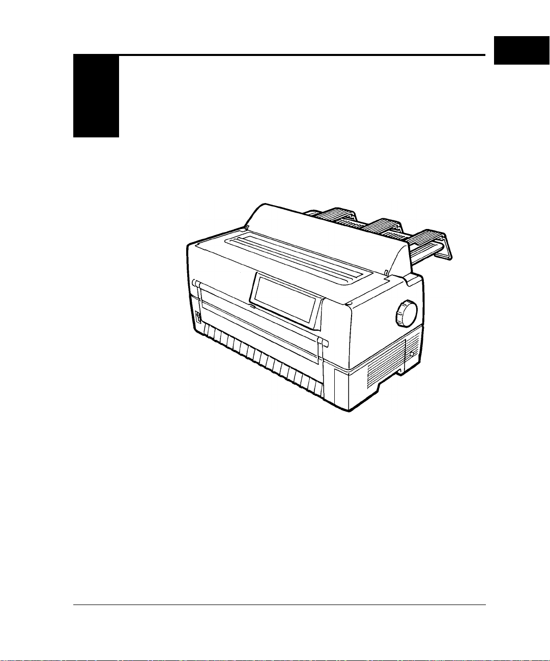
The DL6400 Pro/DL6600 Pro is a 24-dot impact printer used for
image and graphics reproduction.
Figure 1-1 shows the printer.
Figure 1–1 DL6400 Pro/DL6600 Pro printer
User’s Manual 1-1
Page 13
Package Contents
Package
Contents
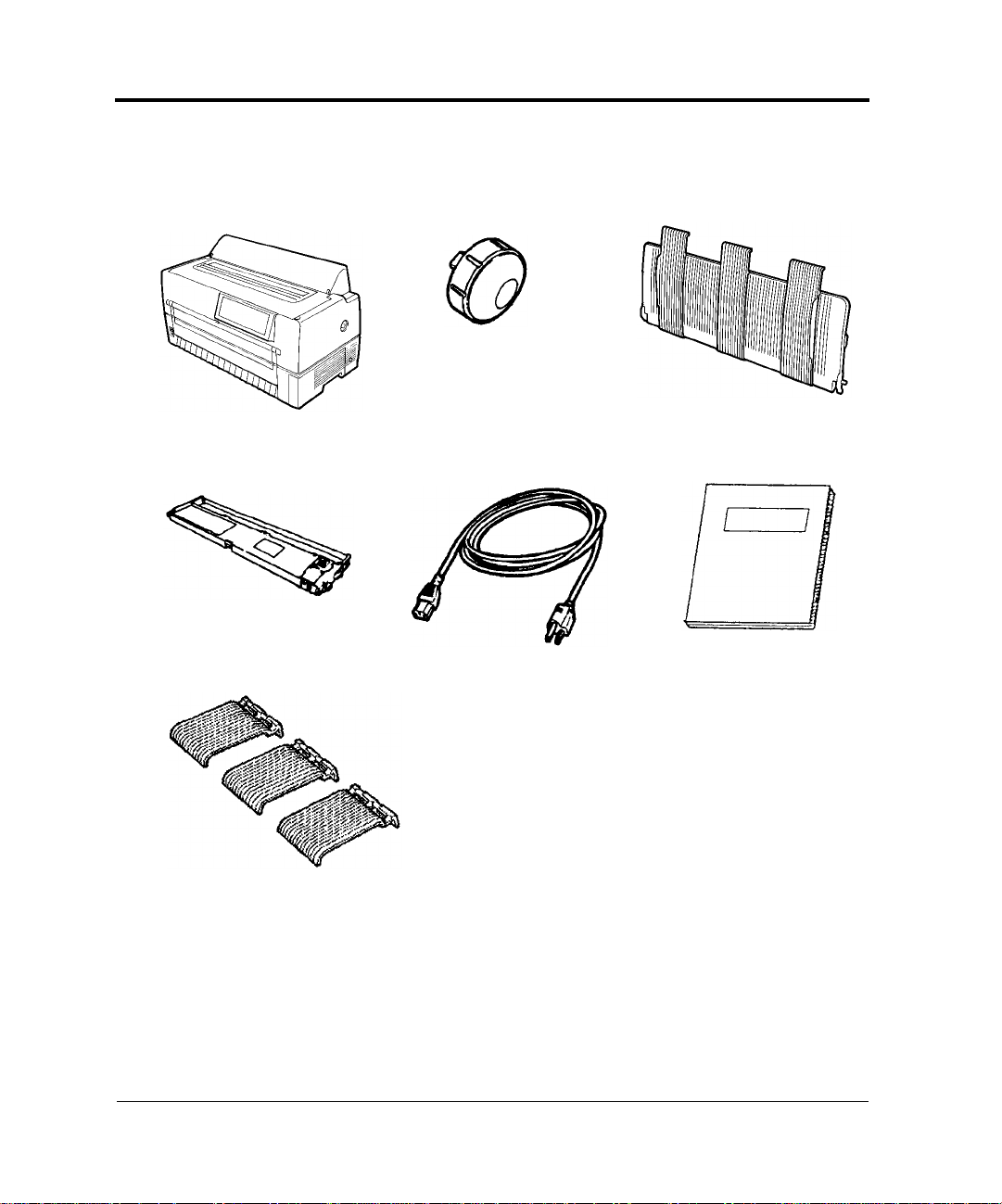
Printer
Ribbon cassette
Check that the printer package contains the items shown in Figure 1-2.
For missing items, contact the Fujitsu sales department.
Platen knob
Paper guide
Maximum length 3 meters
Power cord
User’s manual
Paper guides
Figure 1–2 Components
1-2 User’s Manual
Page 14
Parts and Functions
INTRODUCTION
Parts and
Functions
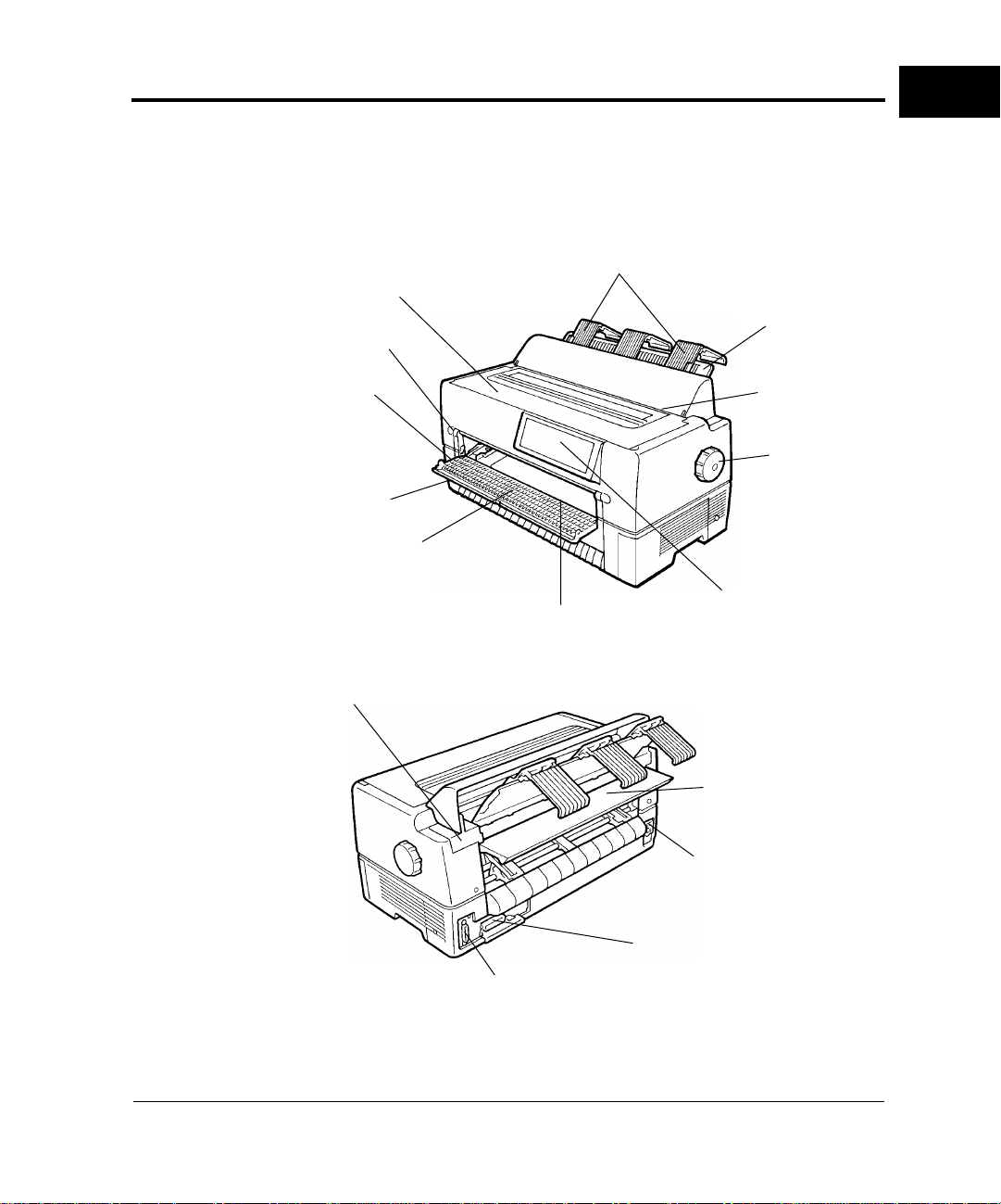
Figures 1-3 and 1-4 show the printer parts.
The numbers in the figures correspond to the parts listed in Table 1-1.
FRONT
q Top cover
!1 Front cover
!0 Power switch
o Front cut-sheet guide
i Front tray
BACK
!6 Back cover
w Back cut-sheet guides
u Cut-sheet tray
e Paper guide
r Paper cutter
t Platen knob
y Control panel
!2 Back auxiliary cover
!3 Power cord connector
!4 Interface cable connector
!5 Cut-sheet feeder connector
Figure 1–3 Parts (1)
User’s Manual 1-3
Page 15
Parts and Functions
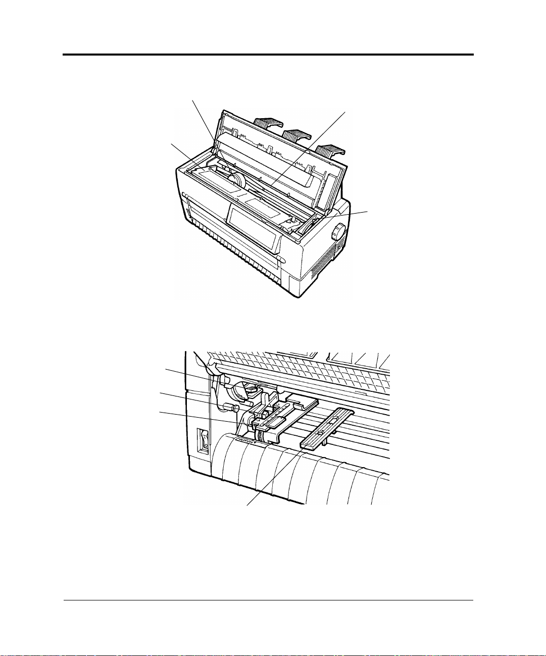
!7 Ribbon cassette
INSIDE
!8 Print head
!9 Platen
@0 Paper thickness lever
SIDES (left side shown)
@1 Jam removal lever
@2 Lock lever
@3 Tractor
@4 Center guide
Figure 1–4 Parts (2)
1-4 User’s Manual
Page 16
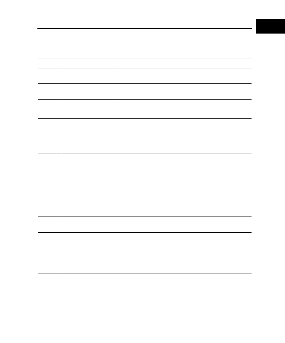
Table 1-1 lists the printer parts and functions.
Table 1–1 Printer parts and functions
Number Part Function
Parts and Functions
INTRODUCTION
q
Top cover Protects the print head and other internal printer
components.
w
Back cut-sheet guides Guides paper into the printer . Set based on the cut-sheet
or continuous forms width.
e
r
t
y
Paper guide Set down for continuous forms and up for cut sheets.
Paper cutter Cuts continuous forms.
Platen knob Turned to feed paper manually.
Control panel Contains the switches and status lamps used to operate
the printer.
u
i
Cut-sheet tray Supports cut sheets during feeding.
Front tray Holds cut sheets for insertion into the printer. Open for
cut sheets and closed for continuous forms.
o
Front cut-sheet guide Set based on the cut-sheet width to guide paper into the
printer.
!0
Power switch Set to "|" to turn power on and to "❍" to turn power
off. When power is on, the power lamp is on.
!1 Front cover Protects components inside the printer. Opened to
replace continuous forms.
!2 Back auxiliary cover Protects components inside the printer. Opened to
replace continuous forms.
!3 Power cord connector Power cord connection.
!4 Interface cable
Cable connection between the printer and processor.
connector
!5 Cut-sheet feeder
connector
Cable connection between the printer and the optional
cut-sheet feeder.
!6 Back cover Removed when the optional cut-sheet feeder is installed.
User’s Manual 1-5
Page 17

Parts and Functions
Table 1–1 Printer parts and functions (Continued)
Number Part Function
!7 Ribbon cassette Contains the printing ribbon. If characters do not print
clearly , replace the ribbon or cassette. A F ujitsu ribbon is
recommended.
!8 Print head Performs actual printing.
!9 Platen Controls and feeds paper.
@0 Paper thickness lever Used to manually adjust paper thickness.
@1 Jam removal lever Turned down to allow jammed paper to be removed
more easily.
@2 Lock lever Locks the tractor.
@3 Tractor Feeds continuous forms.
@4 Center guide Controls continuous forms feeding.
1-6 User’s Manual
Page 18
CHAPTER
SETTING UP
THE PRINTER
2
Removing the
Stopper and
Cushion
Setting Up the Printer
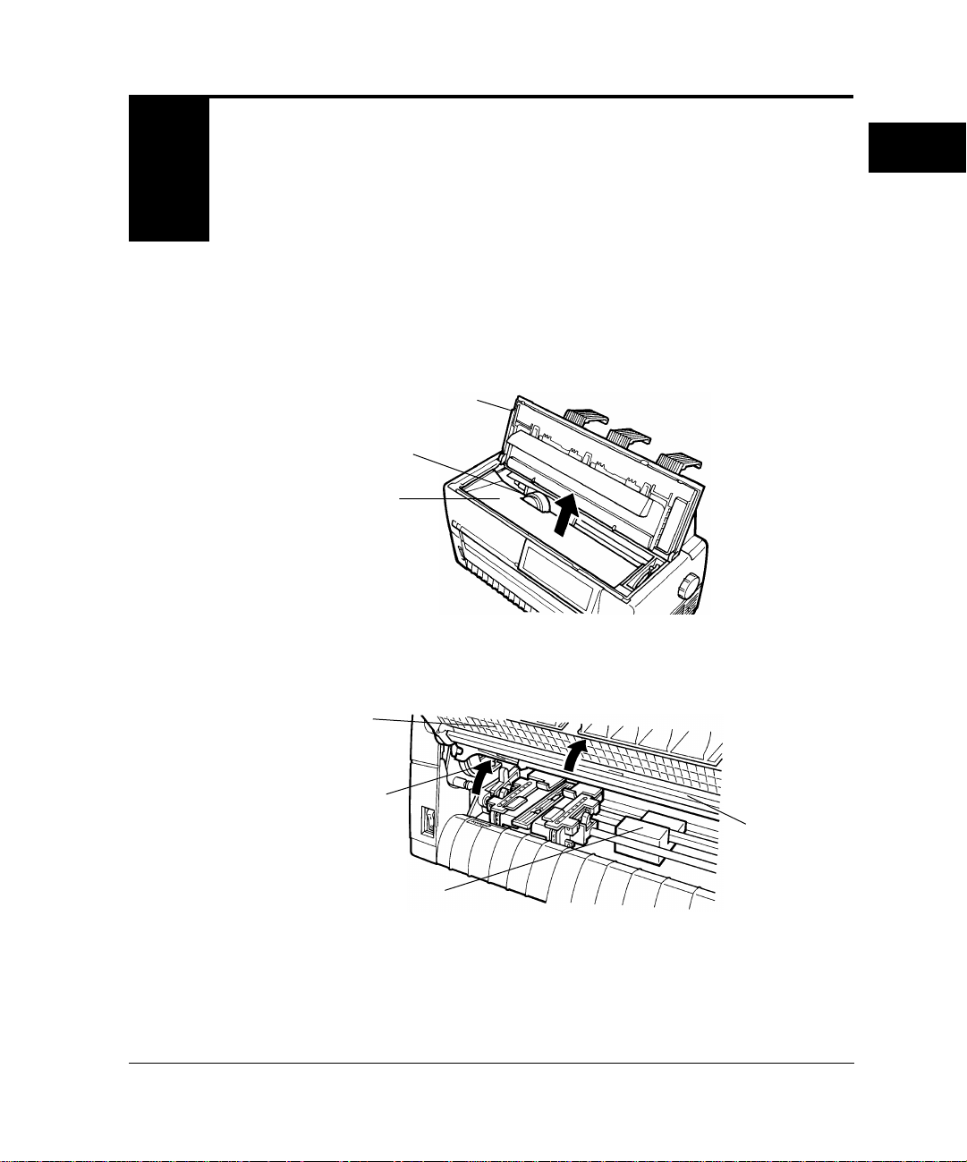
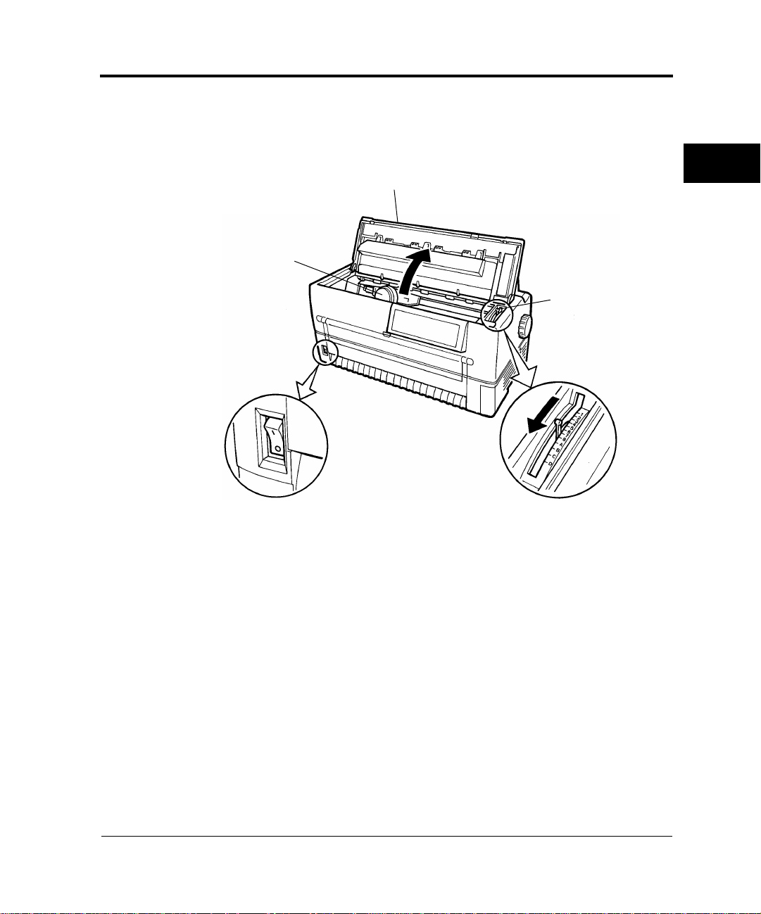
The printer is shipped with a stopper and cushion inside that prevent
vibration and other movement that could cause damage during
shipment.
1. Open the top cover and lift out the stopper as shown by the arrow
in the figure.
Top cover
Print head
Stopper
2. Open the front cover and cut-sheet tray and remove the cushion
from between the tractor shafts.
Front cover
Jam removal lever
Cut-sheet tray
Cushion
3. Check that the jam removal lever is locked.
User’s Manual 2-1
Page 19
Installing the Paper Guide
Installing the
Paper Guide
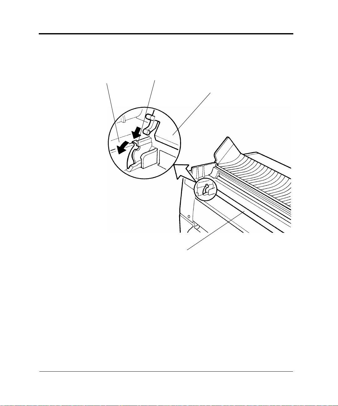
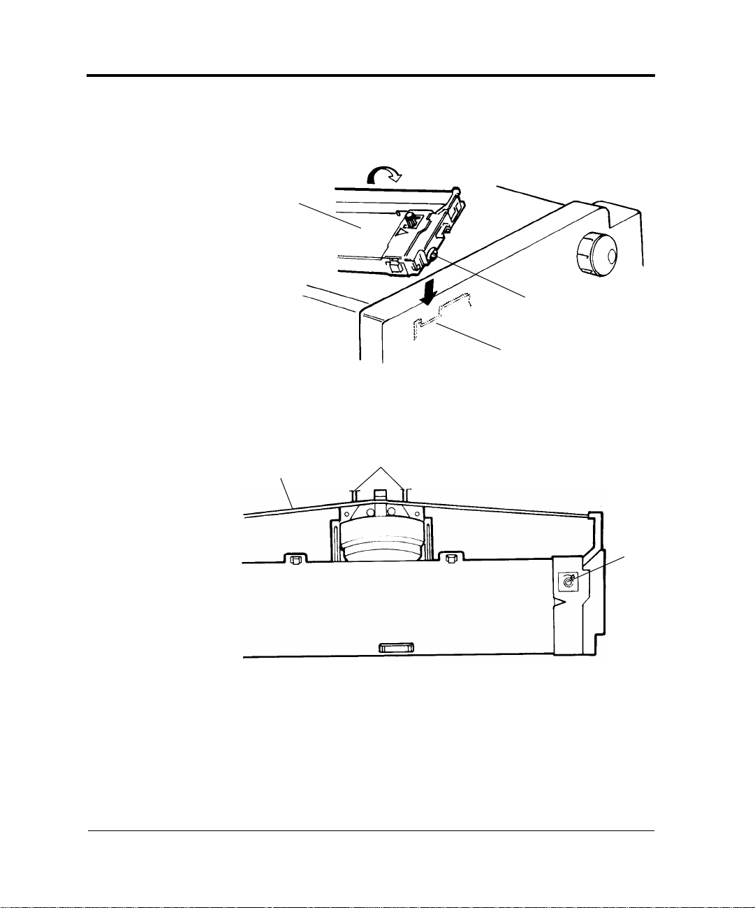
Insert the paper guide, at an angle, into the left and right guide grooves
on the back cover and slide it back into place.
Back cover
Guide groove
Paper guide
Back of printer
Paper exit
2-2 User’s Manual
Page 20
Installing the Platen Knob
Installing the
Platen Knob
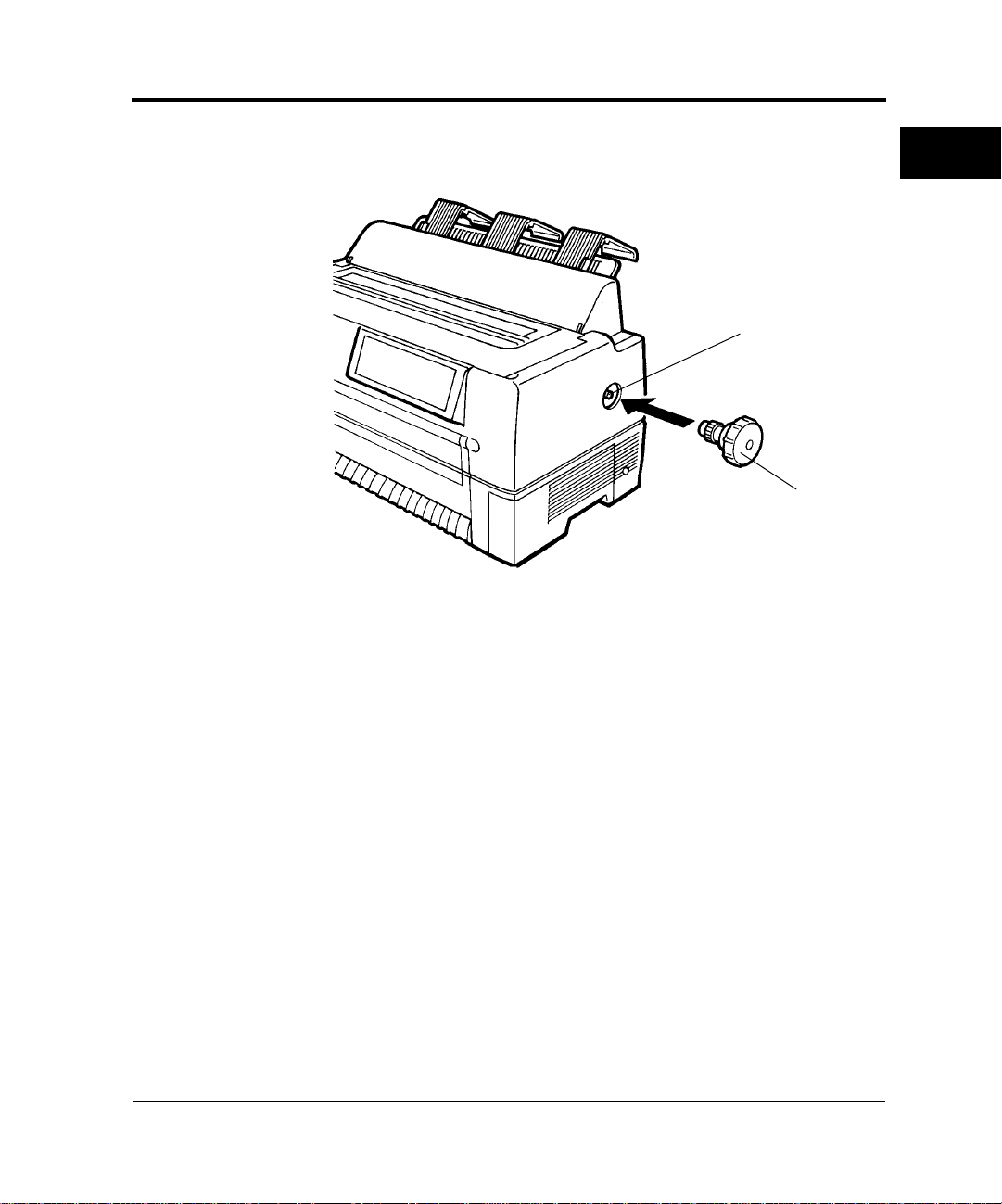
Insert the platen knob and align it with the gear teeth.
Platen shaft
SETTING UP
THE PRINTER
Platen knob
User’s Manual 2-3
Page 21

Connecting the Power Cord
Connecting the
Power Cord
1. Turn off printer power (❍).
2. Connect the power cord to the connector on the back of the printer,
at the right side.
Power cord connector
Power cord
3. Plug the power cord into an outlet.
2-4 User’s Manual
Page 22
Connecting the Interface Cable
Connecting the
Interface Cable
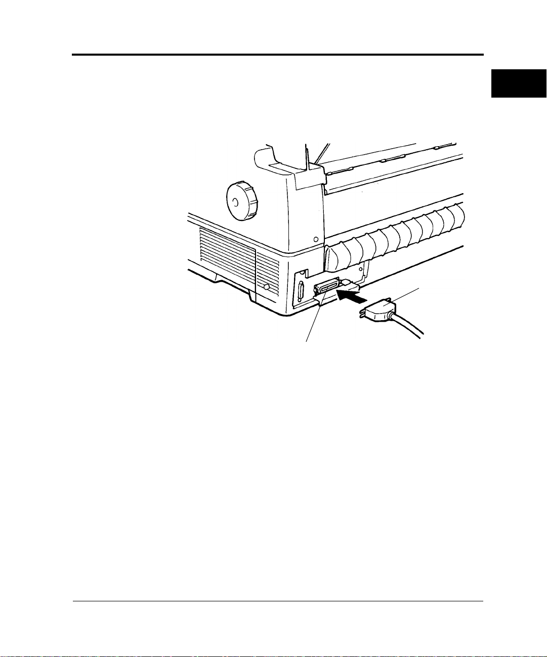
1. Turn off printer and processor power.
2. Connect the interface cable to the connector at the back of the
printer, on the left side. Make sure the orientation is correct. Press
the left and right lock pins down to secure the cable.
Interface cable
Interface cable connector
SETTING UP
THE PRINTER
3. Connect the cable to the computer. For more information, refer to
the computer user's manual.
User’s Manual 2-5
Page 23

2-6 User’s Manual
Page 24

CHAPTER
Ch
3
oosing a
Cassette
Installing the Ribbon Cassette
The ribbon cassette contains a folded ribbon. Handle the ribbon
cassette carefully to ensure that the ribbon is not disordered or
damaged.
Notice:
A Fujitsu ribbon cassette is recommended. Other cassettes may cause
☞
operating problems or damage the print head. Fujitsu takes no
responsibility for print head faults caused by such cassettes.
Use a cassette or subcassette (ribbon only) listed in Table 3-1.
Table 3–1 Ribbon cassette and subcassette
Product Product number Product description
Ribbon cassette CA02460-D115 Ribbon in cassette
Subcassette CA02460-D215 Ribbon only
INSTALLING
THE RIBBON
CASSETTE
User’s Manual 3-1
Page 25

Preparing the Ribbon Cassette
P
reparing the
Ribbon Cassette
1. Remove the two protective tabs used in shipment.
2. Release the ribbon lock.
3. Turn the knob clockwise to check that the ribbon moves smoothly.
Remove the protective tabs
Knob
Lock tabs B
Release the ribbon lock
Notice:
Adjust the paper thickness lever on the printer appropriately for the
☞
forms used. Otherwise, the ribbon may come loose or paper may be
smeared by ink from the ribbon.
3-2 User’s Manual
Page 26
Installing the Ribbon Cassette
I
lli
nsta
ng the
Ribbon Cassette
1. Turn off printer power (❍).
2. Open the top cover of the printer and move the paper thickness
lever to D.
Top cover
Print head
Paper thickness lever
Power switch off (❍)
INSTALLING
THE RIBBON
CASSETTE
3. Manually move the print head to the left side so that it is one third
of the printer width from the left side.
User’s Manual 3-3
Page 27
Installing the Ribbon Cassette
4. Align the pins on both ends of the ribbon cassette with the guide
Ribbon cassette
5. Hook the ribbon over the ribbon guide.
6. Turn the ribbon cassette knob clockwise to remove any slack.
Ribbon
grooves inside the printer. Then press the ribbon cassette down to
install it.
Pin
Guide groove
Ribbon guides
Knob
Ribbon cassette
7. Close the top cover of the printer.
3-4 User’s Manual
Page 28
Removing the Ribbon Cassette
R
emoving the
Ribbon Cassette
1. Turn off printer power (❍).
2. Open the top cover of the printer.
3. Remove the ribbon from the ribbon guide.
4. Pull the ribbon cassette towards you to unlock it and remove the
cassette from the printer.
Top cover
Ribbon cassette
Power switch off (❍)
Ribbon guide
Ribbon
INSTALLING
THE RIBBON
CASSETTE
User’s Manual 3-5
Page 29
Replacing the Subcassette
Replaci
ng the
Subcassette
The ribbon can be replaced up to five times before the entire ribbon
cassette itself must be replaced.
Notice:
A Fujitsu ribbon cassette is recommended. Other cassettes may cause
☞
operating problems or damage the print head. Fujitsu takes no
responsibility for print head faults caused by such cassettes. Replace the
cassette carefully to avoid getting ink on your hands.
Replace the ribbon as follows:
1. Turn off printer power (❍).
2. Remove the ribbon cassette from the printer as explained in
“Removing the Ribbon Cassette” on page 3-5.
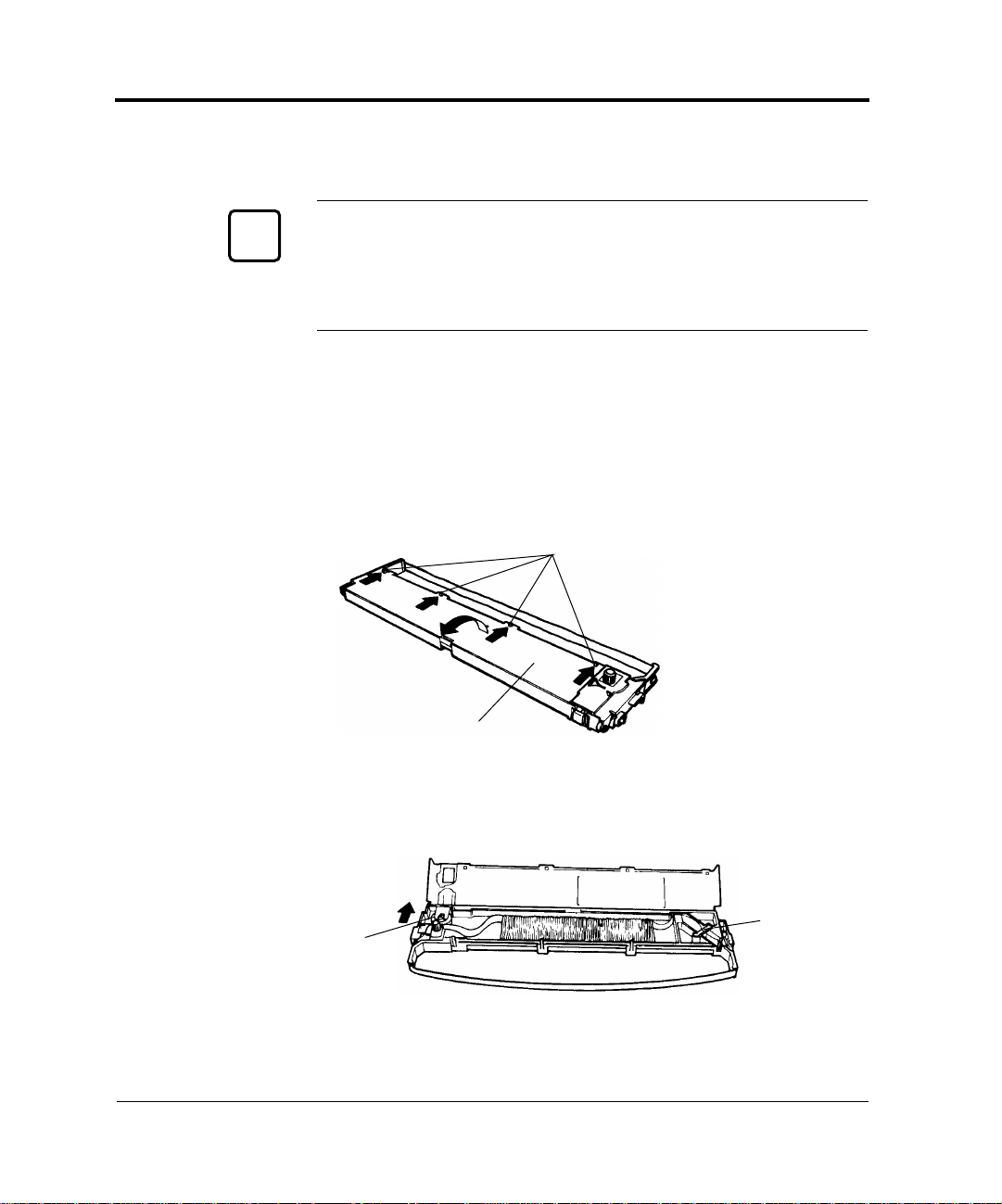
3. Sequentially press each of the four lock tabs A in the directions of
the arrows, starting from either end. Then open the cassette lid.
Lock tabs A
Lid
4. Press feed roller A in the direction of the arrow until it clicks into
place. This procedure loosens the ribbon holder.
Reverse guide
Feed roller A
5. Lift the reverse guide and remove the old ribbon.
3-6 User’s Manual
Page 30
Replacing the Subcassette
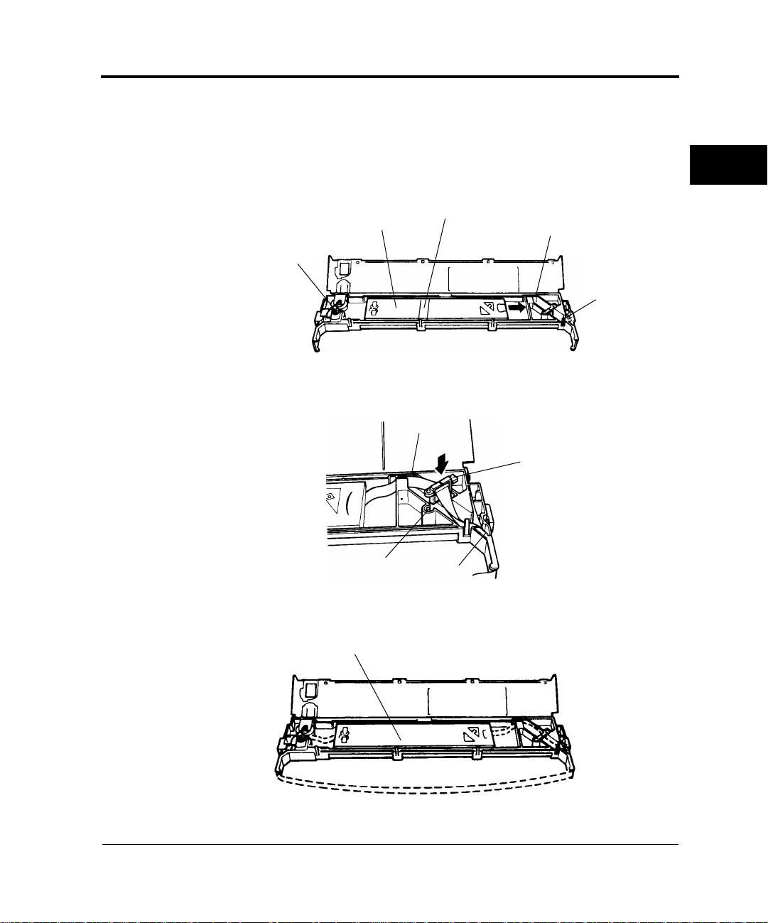
6. When loading the new subcassette into the ribbon cassette, check
that the orientation of the new subcassette is correct. After loading
remove the paper tape.
7. Holding the subcassette casing, slide the bottom of the casing to the
right to remove it.
Casing
Feed roller A
Paper tape
Ribbon path A
Ribbon path B
8. Route the ribbon through paths A and B and insert the reverse
guide.
Ribbon path A
Reverse guide
INSTALLING
THE RIBBON
CASSETTE
Reverse guide insertion
Ribbon path B
9. Thread the ribbon through the cassette as shown by the dotted line
in the figure. Then raise the casing to remove it.
Casing
User’s Manual 3-7
Page 31

Replacing the Subcassette
10. Press lock tabs B in the direction of the arrows to return feed roller
A to its original position. Then close the cassette lid. Turn the knob
clockwise to check that the ribbon moves smoothly.
Knob
Lock tabs B
11. Check off the subcassette replacement column on the cassette label.
12. Install the ribbon cassette (see “Installing the Ribbon Cassette” on
page 3-3).
3-8 User’s Manual
Page 32

CHAPTER
4
Loading
Continuous
Forms (Front)
Loading Paper
1. Turn on the printer power switch ( | ).
2. Press the PAPER PATH button on the control panel to select
FRONT TRACTOR. The FRONT TRACTOR lamp lights.
3. Move the paper guide back as indicated by the arrow in the figure.
(See “Installing the Paper Guide” on page 2-2.)
4. Open the front cover of the printer.
Front cover
Power switch on ( | )
Paper guide
LOADING
PAPER
User’s Manual 4-1
Page 33

Loading Continuous Forms (Front)
5. Raise the cut-sheet tray.
6. Turn the lock levers of the left and right tractors in the direction indicated by the arrow to unlock them.
Lock lever
7. Move the left tractor to the reference point on the lower cover.
Then press the lock lever in the direction of the arrow in the figure
below to lock it.
Cut-sheet tray
Tractor
8. Move the right tractor in alignment with the paper width.
9. Adjust the center guide to the paper width to remove slack in the
paper.
Lock lever
Reference point
Center guide
Tractors
4-2 User’s Manual
Page 34

Loading Continuous Forms (Front)
10. Open the paper holders of the left and right tractors. Align the
forms feed holes with the tractor pins and close the paper holders.
Tractor pins
Paper holders
Tractors
Continuous forms
11. Move the right tractor to add slight tension to the paper. Then press
the lock lever in the direction of the arrow to lock it.
LOADING
PAPER
Lock lever
Tractor
User’s Manual 4-3
Page 35

Loading Continuous Forms (Front)
12. Lower the cut-sheet tray.
13. Close the front cover of the printer.
Cut-sheet tray
Front cover
4-4 User’s Manual
Page 36

Loading Continuous Forms (Front)
14. Press the ONLINE button on the control panel to place the printer
offline. The ONLINE lamp should not be lit.
15. Press the LOAD button (or LOAD/UNLOAD button) on the control panel to load a continuous form automatically.
16. Adjust the position of the print line
To adjust the print line to the position that you require, open the
top cover of the printer and align the red mark of the indicator with
the position you require the bottoms of characters to be.
• Fine forward feed: Holding the ONLINE button down, press
the LF/FF button to feed paper forward in small increments.
• For the operation of the printer with the LCD control panel, see
Appendix E.
• Fine reverse feed: Holding the ONLINE button down, press the
TEAR OFF button to feed paper in reverse in small increments.
Indicator Red mark
LOADING
PAPER
17. Press the ONLINE button on the control panel to place the printer
online. The ONLINE lamp lights.
User’s Manual 4-5
Page 37

Loading Continuous Forms (Rear)
Loading
Continuous
Forms (Rear)
Cutting
Continuous
Forms
Refer to the Rear-Feed Tractor User’s Manual for information on the
rear-feed tractor option.
Forms are cut at perforations 23.3 mm (11/12 inch) above the print
head center when the print head center is on the sixth line. A single line
feed is 4.2 mm (1/6 inch)..
Perforations
23.3 mm
(11/12 in)
Print head center
1. Press the TEAR OFF button on the control panel. The continuous
forms are then automatically loaded to where they are to be cut.
For the operation of the printer with the LCD control panel, see
Appendix E.
2. Open the noise-proof cover.
3. Check that the perforations are at the paper cutter.
4. Cut the continuous forms as shown in the figure below.
4-6 User’s Manual
Page 38

Loading Cut Sheets
Important:
Continuous forms cannot be cut where there are no perforations.
Paper cutter
LOADING
PAPER
Loading Cut
Sheets
1. Turn on printer power ( | ).
2. Press the PAPER PATH button on the control panel to select
FRICTION (friction feed). The FRICTION lamp lights.
3. Raise the paper guide. (See “Installing the Paper Guide” on page
2-2.)
User’s Manual 4-7
Page 39

Loading Cut Sheets
4. Open the front tray.
Paper guide
Power switch on ( | )
Front tray
5. Align the cut-sheet guide with the reference point.
Cut-sheet guide
Reference point
Front guide
4-8 User’s Manual
Page 40

Loading Cut Sheets
6. Insert paper while aligning its left edge with the cut-sheet guide.
Cut-sheet guide
Cut sheet
7. Press the LOAD button (or LOAD/UNLOAD button). The paper
is then loaded to the print start position.
LOADING
PAPER
Notice:
If paper is not loaded correctly, a paper feed error or skewed loading
☞
may occur. Once a cut sheet has been inserted, it is loaded
automatically.
8. Adjust vertical printing as described in step 16 in “Loading Continuous Forms (Front)” on page 4-1.
User’s Manual 4-9
Page 41

Printing on Cut Sheets
Printing on Cut
Sheets
You can print on cut sheets without removing continuous forms from
the tractor section.
1. Press the PAPER PATH button on the control panel to select
FRICTION (friction feed). The FRICTION lamp lights.
Important:
1. Retract continuous forms, if any, from the paper path to the tractor
section. The FRICTION lamp lights.
2. If the lamp does not light to indicate FRICTION, continuous
forms remain in the paper path. Cut the continuous forms and
select FRICTION again.
Continuous forms
4-10 User’s Manual
Page 42

Printing on Cut Sheets
2. Load cut sheets as explained in “Loading Cut Sheets” on page 4-7
without removing the continuous forms.
Cut sheet
Continuous forms
LOADING
PAPER
User’s Manual 4-11
Page 43

Returning to Continuous Forms
Returning to
Continuous
Forms
After printing on cut sheets with continuous forms loaded, you can
easily return to printing continuous forms.
1. Remove cut sheets, if any.
2. Tip back the paper guide.
Paper guide
Front tray
3. Close the front tray.
4. Press the PAPER PATH button on the control panel to select
FRONT TRACTOR or REAR TRACTOR, whichever you want
to use. The FRONT TRACTOR or REAR TRACTOR lamp
lights. Continuous forms are then loaded automatically.
The REAR TRACTOR lamp is for the optional rear-feed tractor.
5. Check the vertical printing position. See “Loading Continuous
Forms (Front)” on page 4-1.
4-12 User’s Manual
Page 44

CHAPTER
5
Using the
Control Panel
Operating the Printer
LED type control panel
1. Layout
Figure 5-1 shows the LED type control panel layout.
Figure 5–1 Control panel layout (LED type)
2. Lamps
Control panel lamps indicate the printer status.
Table 5-1 lists the lamp functions.
OPERATING
THE PRINTER
Table 5–1 Lamp functions (LED type)
*1
Lamp
ONLINE Lights when the printer is online.
PAPER OUT (amber) Changes to red when a paper outage is
1 Lights when MENU 1 is selected.
2 Lights when MENU 2 is selected.
User’s Manual 5-1
Function
detected.
Switched by pressing the MENU button.
Switched by pressing the MENU button.
Page 45

Using the Control Panel
Table 5–1 Lamp functions (LED type) (Continued)
*1
Lamp
Function
FRICTION Lights when cut sheets can be used.
Switched by pressing the PAPER PATH
button.
FRONT TRACTOR Lights when the FRONT tractor can be
used for continuous forms.
Switched by pressing the PAPER PATH
button.
REAR TRACTOR Lights when the REAR tractor can be
used for continuous forms.
Switched by pressing the PAPER PATH
button.
LOCKED Lights when lock mode is on.
Switched by pressing the LOCK button.
Fonts are selected by pressing the FONT
button.
COUR10 Courier (10 cpi)
PRESTG12 Prestige Elite (12 cpi)
COMPRESS17 Compression (17 cpi)
Bold PS Boldface (proportional spacing)
Time PS Timeless (proportional spacing)
N. Sans PS Nimbus Sans (proportional spacing)
DRAFT10 Draft (10 cpi)
DRAFT12 Draft (12 cpi)
MENU FONT The font selected in menu mode becomes
valid in this state.
*1 Lamps glow green unless otherwise indicated.
5-2 User’s Manual
Page 46

Using the Control Panel
3. Buttons (when printer is online)
ONLINE: Places the system offline after it prints the current
line.
LF/FF: Line feed/forms feed button. Feeds forms forward.
Pressing this button continuously for 3 seconds or
more feeds lines forward to the feed point for the
next page (forms feed).
When the cut-sheet feeder is used, pressing this
button continuously for 3 seconds or more unloads
forms. If forms are not at the platen, forms are not
loaded, but a line feed occurs.
TEAR OFF: Places the system in tear off mode and feeds lines to
the forms cutting point. Tear off mode is valid for
continuous forms only.
When this button is pressed, the printer performs
centering, and the ONLINE lamp blinks.
If any button is pressed after forms are cut, the buzzer
sounds, the ONLINE lamp stops blinking, and
forms are fed back to their previous location.
OPERATING
THE PRINTER
LOAD: Loads or unloads forms as follows, depending on the
situation:
• Continuous forms at the platen
Forms are fed backward on the tractor until a paper
outage is detected. If a paper outage has not been
detected when forms have been fed 22 inches,
forms feeding stops.
• Cut sheets at the platen
Cut sheets are unloaded if printing has not started,
and the TOP MARGIN value is made the current
vertical location.
• Cut-sheet feeder set and cut sheets at the platen
Cut sheets are unloaded if printing has not started,
and the next cut sheet is loaded from the cut-sheet
feeder. The TOP MARGIN value is made the
current vertical location.
• Continuous forms or cut sheets being used, cutsheet feeder set, and no forms at the platen
User’s Manual 5-3
Page 47

Using the Control Panel
Forms are loaded, and the TOP MARGIN value is
made the current vertical location.
4. Buttons (when printer is offline)
LOCK: Switches lock mode on or off. The lock mode takes
effect when the offline status changes to online. When
the LOCKED lamp is on, lock mode is on.
When lock mode is on, the font selected on the control
panel is in effect, even if a host command sends an
instruction to change it.
FONT: Selects a font. The font lamps light sequentially each
time the FONT button is pressed. The font lamp that
is on indicates which font is selected.
The font setting takes effect when the offline status
changes to online.
If a command changes the font when lock mode is off,
the font lamp indication does not change.
The font, pitch, and quality for each font selection are
shown here.
Table 5–2 Font button values
Font Quality Characters per inch
COUR10 Courier Letter 10
PRESTG12 Prestige Letter 12
COMPRESS17 Compression CQ 17
Bold PS Boldface Letter Proportional spacing
Time PS Timeless Letter Proportional spacing
N. Sans PS Nimbus Sans Letter Proportional spacing
DRAFT10 Draft Draft 10
DRAFT12 Draft Draft 12
Sequence in which lamps light
MENU FONT The font, quality , and pitch for the font selected in
menu mode are used.
5-4 User’s Manual
Page 48

Using the Control Panel
ONLINE: Places the system online.
MENU: Selects Menu 1 or 2. This button is a toggle.
LF/FF: Feeds lines or forms (same as in online mode).
TEAR OFF: Places the system in tearoff mode (same as in
online mode).
LOAD: Loads or unloads forms (same as in online
mode).
PAPER PATH: Selects FRICTION, FRONT TRACTOR, or
REAR TRACTOR.
ONLINE + LF/FF: Feeds lines forward by 1/180 inch.
ONLINE + TEAR OFF:
Feeds lines backward by 1/180 inch.
ONLINE + LOAD: Permanently stores the load position adjusted
by fine line feeding.
LOCK + FONT: Initializes the printer.
MENU + FONT: Places the system in Setup mode.
See Chapter 8, “Setup Modes,” for more
information.
OPERATING
THE PRINTER
User’s Manual 5-5
Page 49

Using the Control Panel
LCD type control panel
1. Layout
Figure 5-2 shows the LCD type control panel layout.
Figure 5–2 Control panel layout (LCD type)
2. Lamps
Control panel lamps indicate the printer status.
Table 5-3 lists the lamp functions.
Table 5–3 Lamp functions (LCD type)
*1
Lamps
Function
POWER Lights when power is on.
ONLINE
ALARM
*2
Lights when the printer is online.
Changes to red to indicate an alarm.
(amber)
FRICTION
*2
Lights when cut sheets can be used.
Switched by pressing the PAPER PATH button.
FRONT
TRACTOR
*2
Lights when the FRONT tractor can be used for
continuous forms.
Switched by pressing the PAPER PATH button.
REAR
TRACTOR
*2
Lights when the REAR tractor can be used for
continuous forms.
Switched by pressing the PAPER PATH button.
*1 Lamps glow green unless otherwise indicated.
*2 Same as the LED control panel.
5-6 User’s Manual
Page 50

Using the Control Panel
3. LCD
The LCD control panel displays printer status, messages, and
control items on the screen using alphanumeric characters. The
LCD control panel is 24 columns × 2 lines.
4. Buttons
*1
ONLINE
: When the system is online, pressing ONLINE
puts the printer offline after the current lines
are printed. When the printer is offline,
pressing ONLINE puts the printer online.
F1, F2, and F3: Programmable function buttons numbered 1
to 3. The functions depend on the LCD
screen contents.
*2
OPERATING
THE PRINTER
↑ ↓: Switches the direction of an arrow displayed
on the LCD screen.
NEXT DISPLAY: Displays the next LCD screen.
*2
*2
LOAD/UNLOAD: Loads or unloads forms. The operation
depends on the situation.
This button performs the same function as the
LOAD button on the LED control panel. For
details, see 3 and 4 under “LED Type Control
Panel” on pages 5-3 and 5-4.
*1
PAPER PATH
: Selects FRICTION, FRONT TRACTOR, or
REAR TRACTOR.
*1 Same as the LED control panel.
*2 For basic operation information, see Appendix E, “Using the LCD Type Control
Panel.”
User’s Manual 5-7
Page 51

Turning Printer Power On and Off
Turning Printer
Power On and
Off
Test Printing
Turn power on or off as follows:
1. On
Press the power switch at the left on the front of the printer to turn
the printer on ( | ). Depending on the switch settings, lamps will
light.
Notice:
Do not touch any other control panel button when turning power on
☞☞
or off. Otherwise, you may activate a maintenance mode for other than
test printing.
2. Off
Press the power switch to turn the printer off (❍). Lamps go out.
Notice:
Wait at least 3 seconds before turning on power again after turning it
off. Otherwise, a printer fault may occur.
The printer's built-in self-test program prints the firmware version
number, the names of resident emulations, and all available characters.
The test prints 80 characters per line.
For the operation of the printer with the LCD control panel, see
Appendix E.
Make sure paper is loaded. Check that the paper thickness lever is set
to the appropriate position (see “Installing the Ribbon Cassette” on
page 3-3. Then follow these steps to print a self-test page.
1. Turn off the printer.
2. Holding down the LF/FF button, turn the printer back on.
Hold LF/FF down until the printer beeps. Test printing will start
then.
3. To stop printing, press the FONT or MENU button. To remove
the test page, turn the platen knob clockwise.
5-8 User’s Manual
Page 52

Notice:
Do not attempt to use the LF/FF (line feed/forms feed) button to eject
☞
paper in test mode.
4. Check that the printed page resembles the sample in Figure 5-3.
Check that printing is uniform and free of light, dark, or smudged
areas. When printing quality is satisfactory, go to step 5. Otherwise,
correct problems as follows:
a. Check that the ribbon is installed correctly.
b. Check that the paper thickness lever is set to the appropriate po-
sition.
c. Put a new sheet in the cut-sheet tray. Then manually turn the
platen knob to advance the top edge of the paper past the top
roller.
d. Press FONT or MENU to restart printing. If printing quality
does not improve, turn off the printer and contact your dealer.
Test Printing
OPERATING
THE PRINTER
User’s Manual 5-9
Page 53

Test Printing
Figure 5–3 Test printing sample
5. To exit test printing mode, press ONLINE. The printer goes online.
5-10 User’s Manual
Page 54

Demonstration Pattern Printing
Demonstration
Pattern Printing
The printer prints a demonstration pattern showing some printing
features, as shown in Figure 5-4. To print a demonstration pattern,
follow the steps below.
For the operation of the printer with the LCD control panel, see
Appendix E.
1. Load a sheet of letter- or A4-size paper.
2. Turn off the printer.
3. Holding down the FONT button, turn the printer back on.
The printer will start printing the demonstration pattern.
4. For cut sheets, the demonstration stops after printing a page. If a
cut-sheet feeder or continuous forms are used, the demonstration
pattern is repeated. To stop or restart the demonstration during
printing, press ONLINE.
5. To exit demonstration mode, turn off the printer.
OPERATING
THE PRINTER
User’s Manual 5-11
Page 55

Demonstration Pattern Printing
Figure 5–4 Demonstration pattern
5-12 User’s Manual
Page 56

Sensor Detection
Sensor
Detection
The printer has sensors to detect the following conditions:
• Top cover open
The printer goes offline if the top cover is open.
• Paper out
The printer stops printing when it detects a paper outage, cut-sheet
search, or cut-sheet loading.
• Paper jam
The printer stops printing when it detects a paper jam while paper is
being ejected.
• Print head overheating
The printer prints each line in three passes to protect the print head
when overheating is detected.
• Skewed feeding
When the printer detects skewed feed during loading from the front
table, the printer ejects a cut sheet by reverse line feeding.
• Internal lock switch (not available in some countries)
If the top cover is opened during printing, the printer will
automatically stop, and the remainder of the print data from the line
being printed will be lost. Therefore, do not open the top cover
during printing.
• Jam lever open
OPERATING
THE PRINTER
User’s Manual 5-13
Page 57

5-14 User’s Manual
Page 58

CHAPTER
6
Clearing Paper Jams
Continuous
Forms (Front)
When using front-fed continuous forms, remove jammed paper as
follows:
1. Turn off printer power ( ❍ ).
2. Open the front cover.
Front cover
Power switch off ( ❍ )
3. Raise the cut-sheet tray.
4. Lower the green left and right jam removal levers.
CLEARING
PAPER JAMS
Cut-sheet tray
Jam removal lever
User’s Manual 6-1
Page 59

Continuous Forms (Front)
5. Turn the tractor lock levers in the direction indicated by the arrows
in the figure to unlock them. Then open the paper holders.
Lock levers
Paper holders
Tractors
6. Cut the forms just in front of the tractors.
7. Remove jammed continuous forms from the tractors as follows:
a. Remove paper from the paper guide, at the back of the printer.
b. Remove other paper from the front of the printer.
Paper guide
Back of printer
6-2 User’s Manual
Page 60

Print head
Continuous Forms (Front)
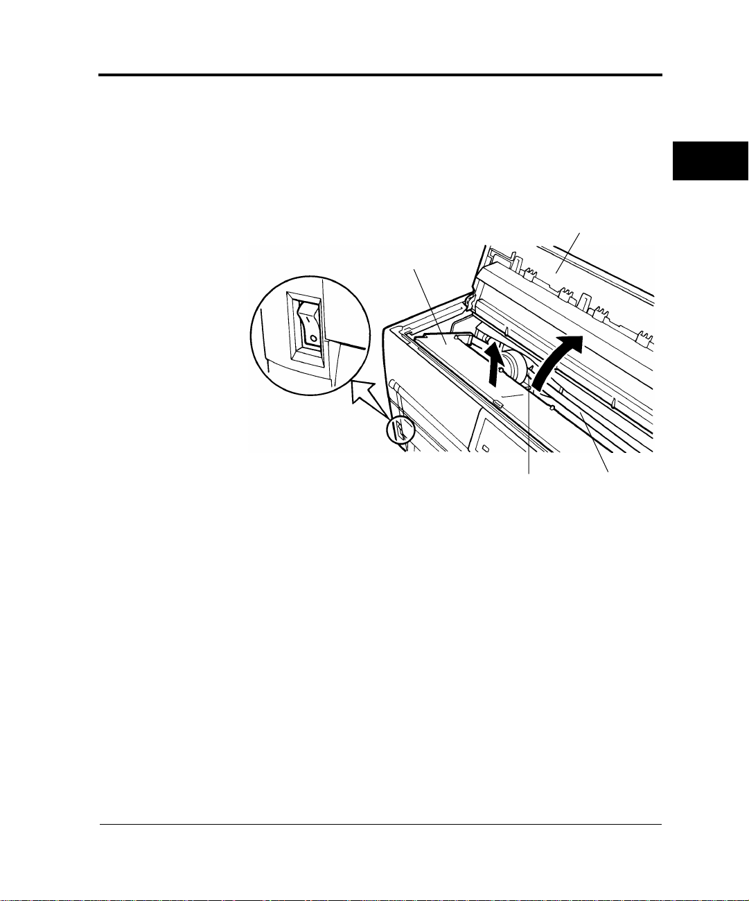
c. Remove jammed paper in the printing section as follows:
1. Open the top cover.
2. Slide the paper thickness lever down to D.
3. Move the print head away from the paper.
4. Remove the paper.
Top cover
CLEARING
PAPER JAMS
Paper thickness lever
8. Lift the green left and right jam removal levers and return them to
their original locations.
9. Lower the cut-sheet tray.
10. Reload forms.
Important:
To prevent paper jams when using continuous forms, align the left and
right holes with the tractor feed holes and ensure that the forms have
no slack.
User’s Manual 6-3
Page 61

Continuous Forms (Rear)
Continuous
Forms (Rear)
Cut Sheets
Refer to the Rear-Feed Tractor User’s Manual for information on the
rear-feed tractor option.
Remove jammed cut sheets as follows:
1. Turn off printer power ( ❍ ).
2. Open the front cover.
Front cover
Power switch off ( ❍ )
3. Raise the cut-sheet tray.
4. Lower the green left and right jam removal levers.
Cut-sheet tray
Jam removal lever
6-4 User’s Manual
Page 62

5. Lower the cut-sheet tray.
Cut-sheet tray
Cut Sheets
6. Remove the jammed cut sheet as follows:
a. Remove paper in the paper guide from the back of the printer.
b. Remove paper other than paper in the paper guide from the
front of the printer.
Paper guide
Back of printer
c. Remove paper in the printing section as explained in step 7 of
“Continuous Forms (Front)” on page 6-3.
CLEARING
PAPER JAMS
Important:
When loading forms after clearing a jam, be sure to insert cut sheets
with the left edge aligned with the paper guide.
User’s Manual 6-5
Page 63

6-6 User’s Manual
Page 64

CHAPTER
7
Continuous
Forms
Paper Specifications
This chapter describes paper that the printer can use.
Any other paper should be tested carefully before use.
1. Size
Figure 7-1 shows the size range for continuous forms.
PAPER
SPECIFICATIONS
T
Y
Measurement Dimensions in mm (in)
Paper width Y 101.6 to 419 (4 to 16.5)
Length between folds T 101.6 (4) or more
Figure 7–1 Size range for continuous forms
User’s Manual 7-1
Page 65

Continuous Forms
2. Number of parts
The printer can handle multipart paper. Table 7-1 lists allowable
combinations for the total number of parts, including the original,
and the ream weight.
Table 7–1 Number of parts and ream weight for continuous forms
Type Number of parts Ream weight in g/m
Single part 1 46, 52, 64, 81
Pressure sensitive
*1
2
3
4
5
[6]
[7]
[8]
39, 50, 64, (81)
39, 50, (64, 81)
39, (50, 64, 81)
39, (50, 64)
39, (50, 64)
39, (50, 64)
39, (50, 64)
2
Carbon-backed
multipart
*1
2
3
4
5
[6]
[7]
[8]
Multipart with car-
*2
bons
2
3
[4]
*1 Ream weights for pressure-sensitive and carbon-backed multipart
forms may differ slightly according to the manufacturer. Select forms
of the weight closest to those in Table. 7-1.
*2 The maximum number of parts for multipart forms with carbons
counts each carbon as one part; that is, the maximum is four.
Important:
39, 52, 64, (81)
39, 52, (64, 81)
39, (52, 64, 81)
39, (52, 64)
39, (52, 64)
39, (52, 64)
39, (52, 64)
34, 46, 52, (64, 81)
34, 46, (52, 64)
34, 46, (52, 64)
1. For specifications for continuous forms loaded from the back of the
printer, refer to the Rear-Feed Tractor User’s Manual.
2. The printer can use only the bottom copy layer of paper with its
weight in parentheses ( ).
7-2 User’s Manual
Page 66

Continuous Forms
3. Characteristics of paper with the number of parts in brackets [ ]
may differ slightly with the manufacturer and should be tested
carefully before use.
4. Paper used for continuous forms differs depending on whether it is
loaded from the front or from the back of the printer. The paper
specifications in Table 7-1 are for forms loaded from the front.
5. The total thickness of multipart paper must not exceed 0.65 mm
(0.025 in).
3. Binding
Select a binding type from Table 7-2.
Table 7–2 Binding for continuous forms with two to six parts
Binding Remarks
Double-sided glued multipart
forms (zigzag spot gluing)
Recommended because:
• Forms remain flexible.
• Parts do not separate or
become misaligned easily.
25.4 mm (1 in) or less
Double-sided paper staples The more parts, the easier the
parts separate or become
misaligned.
76.2 mm (3 in) or less
PAPER
SPECIFICATIONS
User’s Manual 7-3
Page 67

Continuous Forms
Table 7–2 Binding for continuous forms with two to six parts (Continued)
Binding Remarks
Single-sided zigzag spot gluing
and paper staples from back
25.4 mm (1 in) or less
76.2 mm (3 in) or less
Combination of the other two
types of binding
Important:
To avoid paper feed problems, do not bind as shown in the figure.
Line pasting
Staple
Pasted
Stapling
Check that the height of unfolded pasted forms at perforations is 2 mm
(0.08 in) or less.
2 mm (0.08 in)
or less
7-4 User’s Manual
Page 68

4. Binding holes in the scanning area of the sensor
The shaded area shown in the figure indicates the scanning area of
the sensor in which binding holes may lie. Their size is subject to
the following restrictions as described and illustrated.
Any binding hole completely in the shaded area must be 7 mm
(0.28 in) or less in diameter.
Caution:
Always avoid printing on the binding holes. This could damage the
☞
print head.
30 mm
(1.2 in)
10 mm (0.4 in)
First character
Binding holes
Continuous Forms
PAPER
SPECIFICATIONS
5. Perforations
The perforations in continuous forms must meet the following
conditions:
The ratio of cut to uncut areas for single-part continuous forms
must be 3:1.
User’s Manual 7-5
Page 69

Continuous Forms
The uncut dimension at C on each end of horizontal perforations
shown below must be 1 mm or more.
3 mm (0.12 in)
cut
Vertical perforations (middle)
1 mm (0.04 in)
uncut
C
Vertical
perforations
Horizontal perforations
Edge
C
Cut
1 mm (0.04 in) or more
Uncut
When a cross-point cut occurs at the juncture of vertical and horizontal
perforations, printing is inhibited in the shaded area shown in the
figure below. Printing is not allowed in this area to prevent damage to
forms and also to prevent printer faults.
3 mm
(0.12 in)
3 mm
(0.12 in)
Inhibited area
28 mm
(1.1 in)
Cross-point cut
28 mm
(1.1 in)
Cross-point uncutCross-point cut
Notice:
This restriction also applies when the print head moves without
☞
printing.
7-6 User’s Manual
Page 70

Continuous Forms
6. Print area
The figure below shows the print area on continuous forms.
A
F
(in)
A 4.2 (0.17) Characters printed in this
Area Size in mm
Remarks
area may not be neat. A line
spacing of 4.2 mm (1/6 in) or
more prevents characters on
adjacent lines from
Print area
Perforations
(fold)
A
F
B 5.08 to 30
(0.2 to 1.18)
overlapping.
Depending on the paper
width, this size varies as
follows:
101.6 to 119.4 mm (4 to 4.7
in) wide: 5.08 to 9 mm (0.2
PAPER
SPECIFICATIONS
to 0.35 in)
A
F
388.6 to 419 mm (15.3 to
16.5 in) wide: 15 to 30 mm
(0.6 to 1.18 in)
Print area
C 5.08 (0.2)
or more
This size varies with the
paper width and number of
print columns, but must be at
least 5.08 mm (1/5 inch).
D 152 (6.0) This area feeds off the
D
tractors and prevents reverse
line feed.
G
BC
101.6 to 419 mm
(4 to 16.5 in)
E
E Appropriately
29 (1.1)
This value indicates the
paper-end detection point.
F 3.5 (0.14) Do not move the printing
unit horizontally in this area
as paper may be smeared by
the ink ribbon or the printing
unit may be caught at bulges.
G 4.2 (0.17)
User’s Manual 7-7
Page 71

Cut Sheets
Cut Sheets
For cut sheets, use high-quality paper with a light reflection factor of
60 percent or more. Ordinary high-quality white paper has a light
reflection factor of approximately 70 percent. The darker or thinner
the paper, the lower the reflection factor.
1. Size
Width: 90 to 420 mm (3.5 in to A3 horizontal)
Length: 90 to 420 mm (3.5 in to A3 horizontal)
2. Number of parts
The printer can handle multipart paper. Table 7-3 lists allowable
combinations for the total number of parts, including the original,
and the ream weight.
Table 7–3 Number of parts and ream weight for cut sheets
Type Number
of parts
Single
1 <35>, 46, 52, 64, 81
part
Ream weight in g/cm
2
35, 46, 52, 64, 81, 104,
Front Rear
*1
127
Pressure
sensi-
*2
tive
2
3
4
5
[6]
[7]
[8]
39, 50, 64, (81)
39, 50, (64, 81)
39, (50, 64, 81)
39, (50, 64)
39, (50, 64)
39, (50, 64)
39, (50, 64)
Carbonbacked
multi-
*3
part
2
3
4
5
[6]
[7]
[8]
*1 For DL6600 only.
*2 Ream weights for pressure-sensitive and carbon-backed multipart
forms may differ slightly according to the manufacturer. Select forms
of the closest weight to those in the table.
*3 Do not use carbon paper with cut sheets.
7-8 User’s Manual
39, 52, 64, (81)
39, 52, (64, 81)
39, (52, 64, 81)
39, (52, 64)
39, (52, 64)
39, (52, 64)
39, (52, 64)
Page 72

Cut Sheets
Important:
1. Paper with its weight in angle brackets < > must be at least 254
mm (10 in) wide.
2. For multipart forms the ream weight of the bottom sheet being
used must be one of the values in parentheses ( ).
3. Characteristics of paper with the number of parts in brackets [ ]
may differ slightly according to the manufacturer and should be
tested carefully before use.
4. The total thickness of multipart paper must not exceed 0.65 mm
(0.025 in).
3. Binding
Paste sheets at the top.
Important:
Pasted portions must be flexible and free of curl.
Paste here.
Front
Side
PAPER
SPECIFICATIONS
User’s Manual 7-9
Page 73

Labels
4. Print area
The figure below shows the print area on cut sheets.
A
Area Size in mm (in)
Front Rear
Print area
A 4.2 (0.17) 8.5 (0.33)
B 4.2 (0.17) 8.5 (0.33)
*1
5.1 (0.2) to 38 (1.5) or
C
more
B
D 5.1 (0.2) or more
C
90 to 419 mm
(3.5 to 16.5 in)
D
(DL6600 Pro only)
*1 For wide paper, this specification is as follows:
406.4 mm (16 in) wide: 22.5 to 38.5 mm (0.9 to 1.5 in)
419 mm (16.5 in) wide: 36 to 38.5 mm (1.4 to 1.5 in)
Labels
Only labels on the front of continuous forms backing sheets can be
printed.
1. Size
Paper size specifications are the same as for general continuous
forms.
2. Paper thickness
The label and backing sheet together must be 0.2 mm (1/27 in) or
less.
7-10 User’s Manual
Page 74

Label
Labels
Important:
1. The thickness of the backing sheet must be 0.1 mm (1/254 in) or
less.
2. The thickness of the label must be 0.1 mm (1/254 in) or less.
3. Label adhesion
Labels must satisfy the conditions below and not peel off easily.
Winding drum diameter 27 mm
(1.06 in)
Winding angle 180°
PAPER
SPECIFICATIONS
Winding time 24 hours
Drum diameter:
27 mm (1.06 in)
Ambient temperature 40°C
Ambient humidity 30% RH
4. Print area
The figure below shows the print areas on labels.
Fold
Area Size in mm (in)
A 2.54 (0.1) or more
A
C
D
B 6.35 (0.25) or more
C 2.54 (0.1) or more
Print area
C
B
CC
Label
Print area
D 25.4 (1)
B
*1
*1 Lines may not be fed neatly in the print area of D. A line spacing of 1/6 inch or more pre-
vents characters on adjacent lines from overlapping.
User’s Manual 7-11
Page 75

Labels
5. Formats
Use the formats shown below to prevent peeled labels from causing
feed failures, print head damage, and other serious problems.
Example 1:
Leave the four corners and sides uncut between cut portions and do
*1
not remove nonlabel areas
.
This procedure completely prevents label peeling.
Enlarged label:
Leave several cuts on
each of the four sides.
Label
Label
Label
Backing
sheet
Label
Label
Label
Label
Label
Leave uncut portions
on the four corners.
7-12 User’s Manual
Page 76

Example 2:
Labels
Mount
If nonlabel areas
Label
Label
Label
Label
*1 Areas in which no labels adhere to the backing sheet.
*2 R stands for radius. R2 and R3 should be between 2 mm and 3 mm.
*1
must be removed, round label corners.
Label
Label
Label
Enlarged label:
Rounded (R2 to R3)*2 corners
Label
Figure 7–2 Recommended label formats
PAPER
SPECIFICATIONS
User’s Manual 7-13
Page 77

Labels
6. Restriction on APTC option
The printer performs automatic paper thickness detection on the
printing side. For forms with backing sheets removed, the thickness
differs between the label and backing sheet. Measure the thickness
at a label as shown in Figure 7-13.
Front end (or fold)
First printed character
38 mm (1.5 in) 44 mm (1.7 in)
16.93 mm
ABC
12.7 mm
(2/3 inch)
(1/2 inch)
Important:
Ensure that characters are printed in the shaded area.
Figure 7–3 Label arrangement
7-14 User’s Manual
Page 78

Precautions
Precautions
1. Preprinting
When printing using a color with a reflection factor of 60 percent
or less, such as black, do not print in the shaded area shown in the
figure below.
30 mm
(1.18 in)
First character
Important:
10 mm (0.4 in)
Preprinting-inhibited area
The printer uses an autosensor to detect loaded paper in the shaded
area. If the area is preprinted in black, the sensor may fail to detect the
paper because of decreased light reflection.
PAPER
SPECIFICATIONS
Perform preprinting as follows:
a. Do not print horizontal lines thicker than 8 mm (0.3 in)
8 mm (0.3 in) or less
User’s Manual 7-15
Page 79

Precautions
b. When consecutively printing lines that satisfy the specification
in (a), leave an interval of 8 mm (0.3 in) or greater between
lines.
Leave an interval of 8 mm (0.3 in) or greater.
Important:
If the line thickness is 0.5 mm (0.02 in) or less, the interval can be
4 mm (0.16 in) or more.
c. When printing near a paper edge, leave a margin of 8 mm
(0.3 in) or greater.
Top or bottom end of paper
Leave a margin of
8 mm (0.3 in)
or greater.
Important:
If the line thickness is 0.5 mm (0.02 in) or less, the interval can be
4 mm (0.16 in) or more.
d. When printing vertical lines in the shaded area in Figure 7-##,
make lines 0.5 mm (0.02 in) thick or less and do not print more
than one line.
Before printing characters in the shaded area in Figure 7-14, use a
sample to check that the characters can be printed.
7-16 User’s Manual
Page 80

Precautions
2. Binding hole
The shaded area on page 7-15 also places restrictions on binding
holes punched in that area. If punching is necessary, make the holes
7 mm (0.28 in) or less in diameter.
3. Smearing caused by paper feed roller
If the percentage of printing in the shaded areas in the figure below
is high, the paper feed roller may smear paper at loading or ejection.
Design the format to make areas as far away from the printed area
as possible or print a color or pattern on the paper to make smearing
unnoticeable.
Smeared areas in the figure below assume that the left margin is
25.4 mm (1 in). If the left margin is changed, smear areas move
proportionally.
Unit: mm (in)
PAPER
SPECIFICATIONS
24.5
(0.96)
24.5
(0.96)
22 (0.87)
89.5
(3.52)
H
First column
22 (0.87)
144.5
(5.69)
22 (0.87)
199.5
(7.85)
22 (0.87)
284.5
(11.2)
22 (0.87)
345.5
(13.6)
22 (0.87)
User’s Manual 7-17
Page 81

Precautions
4. Miscellaneous
When using special paper that does not conform to specifications,
prepare samples for full trials before using the paper.
Store and handle paper with care to prevent deformation or
damage. Do not store paper where humidity is high.
7-18 User’s Manual
Page 82

CHAPTER
8
Overview
Setup Mode
The printer provides two modes: normal mode, for everyday printer
operations, and setup mode, for selecting printer options and helping
diagnose printer problems.
Setup is performed offline using the printer control panel, an approach
called offline setup, or remotely using a processor or software, an
approach called setup program online setup. This chapter focuses on
offline setup. The section “Performing Online Setup” on page 8-48
applies to all emulations.
Optional printer settings include emulation, font, spacing, page length
and width, serial interface, and top-of-form. Saving settings in the
printer's permanent memory makes them the default settings. Default
settings are activated whenever the printer is turned on. If DPL24C
PLUS is saved as the default emulation, for example, DPL24C PLUS
is activated when the printer is next turned on.
Printer diagnostic functions include SELF-TST, HEX-DUMP, and
V-ALMNT, used in troubleshooting. HEX-DUMP is mainly used by
programmers.
For printers that use the LED control panel, perform offline setup as
follows. Firstly, print setup function, item, and option. Press the
FONT, MENU, or LOCK button to move the yellow arrow on the
print head beneath the desired selection.
SETUP MODE
For printers that use the LCD control panel, perform offline setup as
follows. Firstly, display the setup function, item, and option on the
LCD screen. Press F1, F2, or F3 to select the desired function. On the
LCD display, options can be easily set, and functions un be easily
executline setup function using the LCD control panel, see
Appendix E, “Using the LCD Type Control Panel.”
User’s Manual 8-1
Page 83

Chapter Organization
Chapter
Organization
Activating
Setup Mode
If you are using setup mode for the first time, read “Activating Setup
Mode” on page 8-2 and “Using Setup Mode” on page 8-4 to learn how
setup mode works. Once you understand the basics, read the following
sections to learn how to select printer options compatible with your
processor hardware and software.
To restore printer default values set at shipment, see “Resetting Default
Values” on page 8-36.
For information on using SELF-TST, HEX-DUMP, and V-ALMNT,
see “Using Diagnostic Functions” on page 8-37.
Experienced users can turn to the flowchart at the end of this chapter,
which lists the printer setup functions and options for quick reference.
Before entering setup mode, load continuous forms paper. For
information, see “Loading Continuous Forms (Front)” on page 4-1.
You will need approximately eight sheets of paper to print all setup
selections.
Enter setup mode as follows:
1. Check that forms are loaded.
2. Press ONLINE to place the printer offline.
3. Press FONT and MENU together until the printer beeps.
If a beep does not sound, you are not in setup mode. Place the
printer offline and try again.
Upon entering offline setup mode, the printer prints the
information shown in Figure 8-1.
8-2 User’s Manual
Page 84

Activating Setup Mode
SETUP MODE
(GAP-ADJ is printed only with APTC installed.)
Figure 8–1 Initial setup mode printout
The initial printout contains a header, help menu, and
<<FUNCTION>> menu. The header shows that the printer is offline
and in setup mode. The help menu summarizes setup mode
operations. The <<FUNCTION>> menu lists all functions available in
setup mode. Note that the yellow arrow on the print head is initially
below the SAVE&END function.
Another way to enter setup mode is to turn off the printer and then
turn it on again while pressing the FONT and MENU buttons.
Continue pressing the buttons until the printer beeps.
User’s Manual 8-3
Page 85

Using Setup Mode
Using Setup
Entering setup mode prints the <<FUNCTION>> menu.
Mode
<<FUNCTION>>
SAVE&END MENU1 MENU2 HARDWRE ADJUST CONFIG DEFAULT LIST SELF-TST HEX-DUMP
V-ALMNT GAP-ADJ
Table 8-1 summarizes the setup mode functions.
Table 8–1 Setup mode functions
Function Purpose
SAVE&END Exits setup mode and saves changes made in
MENU1 and
MENU2
HARDWRE Changes hardware options.
ADJUST Changes print adjustment options.
CONFIG Changes configuration options.
GAP-ADJ Sets the head gap, and is displayed when the
(GAP-ADJ is printed only with APTC installed.)
setup mode.
Assigns print features to MENU1 and
MENU2 on the control panel.
printer is equipped with the APTC function.
DEFAULT Resets MENU1 and MENU2 default values
set at shipment.
LIST Prints all currently selected options.
SELF-TST Run the self-test.
HEX-DUMP Prints hexadecimal data dumps.
V-ALMNT Checks and corrects vertical printing
alignment.
To select a function from the <<FUNCTION>> menu, do the
following:
1. Repeatedly press LOCK to position the yellow arrow on the print
head beneath the required function.
2. Press FONT or MENU to select a function. If the function has
items and options, the printer prints the first item and its options.
8-4 User’s Manual
Page 86

Using Setup Mode
MENU1, MENU2, HARDWRE, ADJUST, CONFIG, and
GAP-ADJ contain items with selectable options.
The first three MENU1 items shown in angle brackets < > and
options, for example, are as follows:
<EMULATE> DPL24C+ XL24E ESC/P2
<FONT>
UR 10 PRSTG12 COMPRSD BOLDFCE PICA10 CORRESP OCR-B OCR-A COUR-N COUR-B
CO
COUR-I N.SAN-N N.SAN-B N.SAN-I TIMLS-N TIMLS-B TIMLS-I DOWNLD0 DOWNLD1
<QUALITY> LETTER REPORT DRAFT
To select an option from an item menu, do the following:
1. Repeatedly press LOCK to position the yellow arrow on the print
head beneath the required option.
2. Press FONT to select the option. The printer prints the next function and its options.
3. After selecting options, press ONLINE to reprint the
<<FUNCTION>> menu.
Underlined options are current default settings—that is, the
settings saved in the printer’s permanent memory. In the preceding
example, the default options are Fujitsu DPL24C PLUS emulation,
Courier 10 font, and letter-quality printing.
SETUP MODE
Figure 8-2 summarizes option selection and button use for functions
that do not have options.
The following example illustrates the use of setup mode. The example
shows how to change the font and spacing in MENU2 to Prestige Elite
12 and 12 cpi.
1. Load continuous forms.
2. Enter setup mode.
Press FONT and MENU together until the printer beeps.
3. Select the MENU2 function.
Wait for the printer to stop printing and press LOCK twice to
position the yellow arrow on the print head beneath MENU2. Press
FONT or MENU to select MENU2 and print <EMULATE> and
its options.
User’s Manual 8-5
Page 87

Using Setup Mode
Press FONT
or MENU
Enter setup mode:
Press FONT and MENU
Reprint <<FUNCTION>> menu
Printer prints <<FUNCTION>> menu
Select function: Press LOCK to position
the cursor; then press FONT or MENU
The desired function is selected.
SAVE&END
Printer saves
changes and
exits setup
mode
Press ONLINE
: Functions with items and options
MENU1, MENU2,
HARDWRE, ADJUST,
CONFIG, and GAP-ADJ
LIST, DEFAULT
SELF-TST, HEX-DUMP
V-ALMNT
Select options: Press LOCK
to position cursor; then press
FONT or MENU
Press ONLINE
Press FONT or MENU to
pause or resume
Press LOCK
See “Using Diagnostic Functions”
on page 8-37 for details.
Figure 8–2 Setup mode summary
8-6 User’s Manual
Page 88

Using Setup Mode
4. Select the current emulation.
To leave the emulation unchanged, press FONT to select the
current emulation and print <FONT> and its options.
5. Change the font to Prestige Elite 12.
Press LOCK once to position the yellow arrow on the print head
beneath PRSTG12. Press FONT to select PRSTG12 and print
<QUALITY> and its options.
6. Select the current print quality.
To leave print quality unchanged, press FONT to select the current
print quality and print <PITCH>.
7. Change spacing to 12 cpi and exit MENU2.
Press LOCK once to position the yellow arrow beneath 12 CPI. To
leave MENU1 unchanged, press ONLINE to select 12 CPI and
exit MENU2. The <<FUNCTION>> menu is then reprinted.
8. Exit setup mode, saving the new font and spacing.
The cursor is beneath SAVE&END, so press FONT or MENU to
select SAVE&END. The printer save Prestige Elite 12 and 12 cpi
as the new default settings in MENU2. It then exits setup mode and
goes back online. These settings remain in effect until changed.
SETUP MODE
Important:
1. Load continuous forms before entering setup mode. LF/FF and
LOAD cannot be used to feed or load paper in setup mode.
2. When setup mode is entered, short help menus are printed at the
top of the page. Help menus are also printed when SELF-TST,
HEX-DUMP, or V-ALMNT is selected. Use help menus for quick
reference in setup mode.
3. Functions and options can be printed only one at a time. To move
forward (print the next function) in the item list, press FONT. To
move backward (print the previous function), press MENU.
4. While in the <<FUNCTION>> menu or selecting a function that
contains items and selectable options, press ONLINE to reprint the
<<FUNCTION>> menu.
User’s Manual 8-7
Page 89

Printing a List of Options
5. Underlining beneath the first two letters of an option indicates the
current default setting. For example, 12
CPI indicates that 12
characters per inch is the default value. To change the default
settings, select and save a new setting.
6. While in setup mode, use LIST to print a list of currently selected
options. For details, see “Printing a List of Options” below.
7. To exit setup mode and permanently save changes, select either
SAVE & END or SELF-TST. For details, see “Exiting and Saving”
on page 8-35. To exit setup mode without saving changes, turn the
printer off. Previous default settings are activated when the printer
is turned on again.
Printing a List of
Options
LIST prints a list of all currently selected options. This list is useful for
checking settings when entering or exiting setup mode. To print
options, load continuous forms. Then do the following:
1. Enter setup mode
To center setup mode printer must be offline.
Press FONT and MENU simultaneously. Wait for the printer to
stop printing and check that the <<FUNCTION>> menu is
printed.
<<FUNCTION>>
SAVE&END MENU1 MENU2 HARDWRE ADJUST CONFIG DEFAULT LIST SELF-TST HEX-DUMP
V-ALMNT GAP-ADJ
(GAP-ADJ is printed only with APTC installed.)
2. Select LIST.
Repeatedly press LOCK to position the yellow arrow on the print
head beneath LIST. Next, press FONT or MENU to select LIST.
The printer starts to print a list of current options. Figure 8-3 shows
the default values set at shipment.
Important:
To remove the printout, turn the platen knob until paper can be torn
off at the perforation. The TEAR OFF button cannot be used in setup
mode.
8-8 User’s Manual
Page 90

Printing a List of Options
3. Either select another function or exit setup mode, saving any changes you made.
When exiting setup mode and saving changes, check that the yellow
arrow on the print head is positioned beneath SAVE &END. Then
press FONT or MENU.
SETUP MODE
*
* GAP settings are printed only with APTC installed.
Figure 8–3 Default settings at shipment
User’s Manual 8-9
Page 91

Setting Required Options
Setting
Required
Options
The sections “Changing MENU1 and MENU2 Options” on page
8-11 to “Changing Configuration Options“ on page 8-32 list the
default settings for options by function and tell how to change the
settings.
Menu 1 settings (MENU1)
Menu 2 settings (MENU2)
Hardware settings (HARDWRE)
Print adjustment settings (ADJUST)
Configuration settings (CONFIG)
Head gap adjustment (GAP-ADJ)
Most selectable options simply change print features such as the type
face and page format. Some options, however, must be selected
correctly for the printer to work properly with hardware and software.
Table 8-2 lists these options.
Table 8–2 Required options
Function Item Options
MENU1 EMULATE The emulation selected for the printer
and software must match. The
emulation selected at printer setup (see
Chapter 2, “Setting Up the Printer”)
need not be changed unless you want
to switch to a different emulation. The
emulation assigned to MENU1 is the
default setting when the printer is
turned on.
See “Changing MENU1 and MENU2
Options” on page 8-11.
MENU2 None If MENU2 is used, the selected
emulation must match that of the
software.
See “Changing MENU1 and MENU2
Options” on page 8-11.
8-10 User’s Manual
Page 92

Changing MENU1 and MENU2 Options
Table 8–2 Required options (Continued)
Function Item Options
Changing
MENU1 and
MENU2 Options
HARDWRE
FORMAT
BAUD-RT
PROTOCL
DSR
DUPLEX
For a serial interface model, serial
interface options selected for the
printer must match those of the
software or operating system.
Otherwise, the printer will not print or
will print incorrectly.
See “Changing Hardware Options” on
page 8-24.
ADJUST None If your software does not specify the
top margin of the page, use the
printer's default top-of-form setting:
25.4 mm (1 in) from the top of the
paper. If the software does specify the
top margin, change the default setting
to 4.2 mm (1/6 in).
See “Changing Print Adjustment
Options” on page 8-28.
MENU1 and MENU2 set print options for MENU1 and MENU2 on
the control panel. In normal (nonsetup) mode, these menus are easily
switched.
Table 8-3 lists MENU1 and MENU2 items and options in the order
they are printed. For some emulations, some items are not defined and
some options differ.
SETUP MODE
MENU1 is active when the printer is first turned on.
The printer emulation must match that of the software. Otherwise, the
printer will not work correctly. If you regularly use two different
emulations, assign the most frequently used to MENU1 and the other
to MENU2. All settings available for MENU1 and MENU2 are
optional. Some items and options differ with the emulation.
To determine which features specific software supports, refer to the
software documentation.
User’s Manual 8-11
Page 93

Changing MENU1 and MENU2 Options
The procedure for changing the MENU1 and MENU2 options
follows Table 8-3.
Table 8–3 MENU1 and MENU2 options
MENU 1 or MENU2
item
<EMULATE>
<FONT>
Options Description
Select the same emulation as that of the software.
DPL24C+
Fujitsu DL-series printers
(DPL24C PLUS command set)
XL24E
ESC/P2
IBM Proprinter XL24E printers
Epson printers using the ESC/P2 command set
Note:
Changing the emulation resets all MENU1 or
MENU2 options to the default values set at shipment.
For each font below, the recommended pitch settings
are given in parentheses. When you change the font, be
sure to also change the pitch, if required.
COUR 10
PRSTG 12
COMPRSD
BOLDFCE
PICA 10
CORRESP
OCR-B
OCR-A
COUR-N
COUR-B
COUR-I
N.SAN-N
N.SAN-B
N.SAN-I
TIMLS-N
TIMLS-B
TIMLS-I
DOWNLD#
Font 0 or font 1 in the printer’s download RAM
8-12 User’s Manual
Page 94

Changing MENU1 and MENU2 Options
Table 8–3 MENU1 and MENU2 options (Continued)
MENU 1 or MENU2
item
<QUALITY>
Options Description
Select the print quality that meets most needs.
LET
TER
Letter quality. Highest resolution, slowest print speed,
invalid for compressed fonts.
REPORT
Report quality. Lower resolution than letter quality,
but prints at twice the speed. For double speed
regardless of font, use the correspondence font because
its quality is higher than report.
DRAFT
Regular draft quality. Lower resolution than report
quality, but prints at three times letter speed.
<PITCH> ## CPI
2.5, 3, 5, 6, 10
horizontal inch (cpi)
PROP SP
Proportional spacing (1/12 inch for a space)
<LINE SP> ## LPI 1, 2, 3, 4, 5, 6
6 lpi: 3 lpi (double spacing):
ABCD ABCD
ABCD
ABCD ABCD
ABCD
ABCD ABCD
ABCD
, 12, 15, 17, 18, or 20 characters per
, 7, or 8 lines per vertical inch (lpi)
SETUP MODE
User’s Manual 8-13
Page 95

Changing MENU1 and MENU2 Options
Table 8–3 MENU1 and MENU2 options (Continued)
MENU 1 or MENU2
item
<CHAR-W>
<CHAR-H>
Options Description
If necessary , also change the spacing when 2 TIMES or
4 TIMES is selected.
NORMAL
2 TIMES Double character width:
4 TIMES
NORMAL
2 TIMES Double character height:
*1
Standard character width:
ABCD
ABCD
Quadruple character width:
ABCD
If necessary, also change the line spacing when 2
TIMES or 4 TIMES is selected.
Standard character height:
ABCD abcd
ABCD abcd
4 TIMES
*1
Quadruple character height:
ABCD abcd
8-14 User’s Manual
Page 96

Changing MENU1 and MENU2 Options
Table 8–3 MENU1 and MENU2 options (Continued)
MENU 1 or MENU2
item
<ATTRIB>
<PAGE LG>
<LFT-END>
Options Description
Select an attribute to add emphasis. Only one attribute
can be selected at a time.
NONE
ITALICS
CONDNSD
*1
SHADOW
BOLD
Standard characters (no attributes)
Italic printing
Condensed printing
DDoouubbllee pprriinnttiinngg wwiitthh aa sslliigghhtt ooffffsseet
Double printing at the same location
Specifies the page length in inches.
## IN
DPL24C PLUS and IBM XL24E emulations:
3.0, 3.5, 4.0, 5.0, 5.5, 6.0, 7.0, 8.0, 8.5, 11.0
(letter size), 11.6 (A4 size), 12.0, 14.0, or 18.0 inches
Epson ESC/P2 emulation:
4.0, 4.5, 5.0, ..., 11.0
Specifies the print start column for modifying the left
margin. Printing starts at this column plus the
software-specified left margin.
t
SETUP MODE
, 11.5, ..., 22.0 inches
## COLM
User’s Manual 8-15
Column 1, 2, 3, ..., 41
<LFT-END>
Softwarespecified
margin
Page 97

Changing MENU1 and MENU2 Options
Table 8–3 MENU1 and MENU2 options (Continued)
MENU 1 or MENU2
item
<TOP-MRG>
Options Description
Specifies the number of space lines for the top margin.
The resultant blank space is the <TOP-MRG> setting
minus one line.
The total size of the top margin is the preceding value
plus these two settings: top-of-form (default = 1 inch)
plus software-specified top margin. If using software to
specify the top margin, use the default setting (one
line) for <TOP-MRG>.
## LINE1
1, 2, 3,4, 5, 6, 7, 8, 9, or 10 lines
Top-of-form
Top margin setting
8-16 User’s Manual
Page 98

Changing MENU1 and MENU2 Options
Table 8–3 MENU1 and MENU2 options (Continued)
MENU 1 or MENU2
item
<LANGUGE>
Options Description
Selects a language.
Two-pass means that diacritical marks are printed
separately from letters printed without reduction.
The first list of languages is common to all emulations.
Subsequent lists show options specific to other
emulations.
USA
UK
GERMAN
SWEDISH
PAGE437
PAGE850
PAGE860
PAGE863
PAGE865
ECMA94
ISO8859
PG852
PG852-T
PG855
PG866
HUNGARY
HUNG-T
SLOV
SLOV-T
POLISH
POLSH-T
MAZOWIA
MAZOW-T
LATIN2
LATIN2-T
KAMENIC
KAMEN-T
TURKY
TURKY-T
CYRILIC
IBM437
American English (same as code page 437)
British English
German
Swedish
Code page 437
Code page 850
Code page 860
Code page 863
Code page 865
ECMA 94
ISO 8859-1
Code page 852
Code page 852 two-pass
Code page 855
Code page 866
Hungarian
Hungarian two-pass
Slovenian
Slovenian two-pass
Polish
Polish two-pass
Mazowian
Mazowian two-pass
Latin 2
Latin 2 two-pass
Kamenicky
Kamenicky two-pass
Turkish
Turkish two-pass
Cyrillic
IBM 437
SETUP MODE
User’s Manual 8-17
Page 99

Changing MENU1 and MENU2 Options
Table 8–3 MENU1 and MENU2 options (Continued)
MENU 1 or MENU2
item
<LANGUGE>
(continued)
Options Description
IBM851
ELOT928
PG-DHN
LATIN-P
ISO-LTN
LITHUA1
LITHUA2
IBM 851
ELOT 928
Code page DHN
Latin Polish
ISO Latin
Lithuanian 1
Lithuanian 2
MIK
MACEDON
Macedonian
PG-MAC
ELOT927
ABG
ABY
DEC GR
GREEK 11
PG862
HBR-DEC
HBR-OLD
ISO-TUK
*2
FRENCH
ITALIAN
SPANISH
DANISH1
DANISH2
FINNISH
NORWEGN
*3
DANISH1
ITALIAN
SPANSH1
SPANSH2
JAPAN
NORWEGN
LATIN A
FRENCH
DANISH2
ISO Turkish
French
Italian
Spanish
Danish I
Danish II
Finnish
Norwegian
Danish I
Italian I
Spanish I
Spanish II
Japanese
Norwegian
Latin American
French I
Danish II
KOREA
LEGAL
8-18 User’s Manual
Page 100

Changing MENU1 and MENU2 Options
Table 8–3 MENU1 and MENU2 options (Continued)
MENU 1 or MENU2
item
Options Description
<CHR-SET> SET 1
SET 2
*3
ITALIC
GRAPHIC
<AGM>
*4
OFF
ON
<PRF-SKP>
SKIP
NO-SKIP
IBM character set 1
IBM character set 2
If a downloaded (soft) font is used, the character set for
that font overrides the <CHR-SET> setting.
Italic characters possible
Graphics characters (ruled lines) possible
Specifies that alternate graphics mode (AGM) is off.
The unit of line spacing is 1/72 or 1/216 of an inch.
Specifies that alternate graphics mode (AGM) is on.
The unit of line spacing is 1/60 or 1/180 of an inch.
For continuous forms, specifies whether an inch is
skipped over the perforation. If not using software to
specify a bottom margin, select SKIP when using thick
multipart forms.
One inch is skipped over the perforation.
The perforation is not skipped. Printing continues in
the bottom margin of the page.
SETUP MODE
<WIDTH> 13.6 IN
11.4 IN
11.0 IN
8.0 IN
<ZEROFNT>*2
13.6-inch page width
11.4-inch page width
11-inch page width
8-inch page width
Specifies whether the number zero is printed with a
slash. The slash is useful for distinguishing the capital
letter “O” from the number “0.”
This setting is invalid for some software fonts.
NO-SLSH
SLASH
User’s Manual 8-19
0
Ø
 Loading...