

Page 1

User Guide
KVM series4-0812/1622/3242
Keyboard/Video/Mouse Switch English/Deutsch/Français/Español/Italiano/日本語
Page 2

Page 3

KVM series4-0812/1622/3242
Software Installer/User Guide
Edition February 2011
Page 4

Comments... Suggestions... Corrections
The User Documentation Department would like to know your opinion of this
manual. Your feedback helps us optimize our documentation to suit your
individual needs. Fax forms for sending us your comments are included in the
back of the manual. There you will also find the addresses of the relevant User
Documentation Department.
Certified documentation
according to DIN EN ISO 9001:2000
To ensure a consistently high quality standard and user-friendliness, this
documentation was created to meet the regulations of a quality management
system which complies with the requirements of the standard DIN EN ISO
9001:2000.
Copyright and Trademarks
Copyright © Fujitsu Technology Solutions GmbH 2010.
All rights reserved.
Delivery subject to availability; right of technical modifications reserved. All
hardware and software names used are trademarks of their respective
manufacturers.
This manual is printed on
paper treated with
chlorine-free bleach.
Page 5

Contents
Contents
1. Product overview 1
1.1 About Fujitsu KVMs4 Client Software 1
1.2 Features and benefits 1
1.3 System components 2
1.4 Operating features 3
1.5 Target device naming 3
2. Installation and startup 7
2.1 Getting started 7
2.2 Installing the software 9
2.3 Uninstalling the software 10
2.4 Starting the software 11
2.5 Configuring switches and user access to target devices 12
3. Explorer 15
3.1 About the Explorer 15
3.2 Window features 15
3.3 Customizing the window display 17
3.4 Adding a switch 18
3.5 Accessing switches 21
3.6 Accessing target devices 22
3.7 Customizing properties 24
3.8 Customizing options 29
3.9 Managing folders 34
3.10 Assigning units 35
3.11 Deleting 36
3.12 Renaming 37
3.13 Managing the software database 38
4. Video Viewer 41
4.1 About the Video Viewer 41
4.2 Using preemption 45
4.3 Using exclusive mode 47
4.4 Using digital share mode 48
4.5 Using stealth mode 50
4.6 Using scan mode 51
4.7 Adjusting the view 53
4.8 Adjusting mouse options 56
590-1059-640A
5
Page 6

Contents
4.9 Adjusting general options 57
4.10 Adjusting the Video Viewer toolbar 58
4.11 Using macros 59
4.12 Using virtual media 60
Appendix A: Updating the KVMs4 Client Software 67
Appendix B: Virtual media 69
Appendix C: Keyboard and mouse shortcuts 71
Appendix D: Ports used by the software 75
Appendix E: Technical Support 77
590-1059-640A6
Page 7

1. Product overview
1.1 About Fujitsu KVMs4 Client Software
With Fujitsu®KVMs4 client software, a cross-platform management application,
you can add and manage multiple switches and attached target devices. The
cross-platform design offers compatibility with most commonly-used operating
systems and hardware platforms. Each switch handles authentication and access
control individually, placing system control at the point of need.
The software utilizes browser-like navigation with a split-screen interface,
providing you with a single point of access for all switches. Use the software to
manage existing switches, install a new target device, or open a session to a
target device. Built-in groupings such as Devices, Sites, and Folders provide a
way to select the units to view. Use the search and sort capabilities to find any
unit.
1.2 Features and benefits
Easy to install and configure
Wizard-based installation and online help simplify initial system configuration.
You can use the graphical interface to manage and update switches, target
devices, and adapter cables.
Powerful customization capabilities
You can tailor the software to fit specific system needs, using built-in groups or
creating your own. You can customize unit names, field names, and icons for
maximum flexibility and convenience. Use names that are meaningful to you to
quickly find any target device.
Extensive switch management
The KVMs4 switch firmware includes an integrated web interface that can be
used for configuring KVMs4 switches and configuring and accessing connected
target devices. You can add and manage multiple switches in one system with
the software. After a new switch is added, you can configure operating
parameters, control and preempt user sessions to target devices, and execute
numerous control functions, such as rebooting and upgrading the switch. You
can enable Simple Network Management Protocol (SNMP) traps, configure target
devices, and manage user databases.
You can use the software to manage the following Fujitsuswitches:
590-1059-640A
1
Page 8

1. Product overview
• KVMs4-0812 switch: The KVMs4-0812 switch includes a digital port for
KVM-over-IP access, 8 ARI ports for connecting adapter cables and target
devices, adds a second dedicated local path for the ACI port, smart card
support, two power receptacles, and one VGA and four USB ports, virtual
media capability for two local users and one remote user.
• KVMs4-1622 switch: The KVMs4-1622 switch includes two digital ports for
KVM-over-IP access, 16 ARI ports for connecting adapter cables and target
devices, adds a second dedicated local path for the ACI port, smart card
support, two power receptacles, and one VGA and four USB ports, virtual
media capability for two local users and up to two remote users.
• KVMs4-3242 switch: The KVMs4-3242 switch includes four digital ports for
KVM-over-IP access, 32 ARI ports for connecting adapter cables and target
devices, adds a second dedicated local path for the ACI port, smart card
support, two power receptacles, and one VGA and four USB ports, virtual
media capability for two local users and up to four remote users.
Authentication and authorization
Administrators can configure each switch either to use local user databases on
the switch or to use databases on an LDAP server for user authentication and
authorizations checking. Local authentication is always used, either as the
primary authentication method or as a fallback method when LDAP
authentication is configured.
The switch can be configured to use LDAP for authentication only with the local
databases used for authorizations checking.
After users log in to a switch, the software caches their credentials (user name
and password) for the duration of the session.
1.3 System components
The software contains the following major components.
Explorer
The Explorer is the primary point of control for accessing the software features
and functionality. From the Explorer, you can view the switches and target
devices defined in the local database. Built-in groupings such as Appliances and
Devices provide different ways to list units. You can create custom groups of units
by adding and naming folders. Other groupings are also available, based on
custom fields that you can assign to units.
590-1059-640A
2
Page 9

1.4 Operating features
From the Explorer Devices list, you can select a device from the list of target
devices and start a KVM session with the device. Starting a KVM session brings
up a Video Viewer. From the Explorer Appliances list, you can select a switch to
configure.
Video Viewer
Users access and manage target devices through the Video Viewer. You can use
predefined macros and choose which macro group is displayed on the Video
Viewer Macros menu. You can open the Video Viewer to connect to target
devices on KVMs4 switches. For more details, see "About the Video Viewer" on
page 41
The Video Viewer also provides access to the Virtual Media window. You can
use the Virtual Media window to map a physical drive, such as a disk, CD-ROM,
or DVD-ROM data drive, onto a target device so that the media device is
available to the target device even though it is not directly connected. For more
information on the Virtual Media window, see "Using virtual media" on page 60.
1.4 Operating features
"Keyboard and mouse shortcuts" on page 71 lists the Explorer navigation
shortcuts. Other components also support full keyboard navigation in addition to
mouse operations.
1.5 Target device naming
The KVMs4 client software requires that each switch and target device have a
unique name. To minimize the need for operator intervention, the software uses
the following procedure to generate a unique name for a target device whose
current name conflicts with another name in the database.
During background operations (such as an automated operation that adds or
modifies a name or connection), if a name conflict occurs, the conflicting name is
automatically made unique. This is done by appending a tilde (~) followed by an
optional set of digits. The digits are added in cases where adding the tilde alone
does not make the name unique. The digits start with a value of one and are
incremented until a unique name is created.
During operations, if you or another user specifies a non-unique name, a
message informs the corresponding user that a unique name is required.
590-1059-640A
3
Page 10

1. Product overview
Target device name displays
When a switch is added, the target device names retrieved from the switch are
stored in the software database. The operator can then rename a target device in
the Explorer. The new name is stored in the database and used in various
component screens. This new target device name is not communicated to the
switch.
Since the software is a decentralized management system, you can change the
name assigned to a target device on the switch at any time without updating the
software database. Each operator can customize a particular view of the list of
target devices being managed.
Since you can associate more than one name with a single target device - one on
the switch and one in the software - the software uses the following rules to
determine which name is used:
• The Explorer only shows the target devices listed in its database, with the
name specified in the database. In other words, the Explorer does not talk to
the switch to obtain target device information.
• The Resync Wizard overwrites locally-defined target device names only if the
switch target device name has been changed from the default value. Nondefault target device names that are read from the switch during a
resynchronization override the locally-defined names.
Sorting
In certain displays, the software component displays a list of items with columns
of information about each item. If a column header contains an arrow, you can
sort the list by that column in ascending or descending order.
To sort a display by a column header, click the arrow in a column header. The
items in the list are sorted according to that column. An upward-pointing arrow
indicates the list is sorted by that column header in ascending order. A
downward-pointing arrow indicates the list is sorted by that column header in
descending order.
IPv4 and IPv6 network address capabilities
The KVMs4 client software is compatible with systems using either of the
currently supported Internet Protocol Versions, IPv4 (default) or IPv6. For KVMs4
switches, you can change the network settings and select IPv4 and IPv6 mode
simultaneously.
590-1059-640A
4
Page 11

1.5 Target device naming
The IPv4 mode connection can be either a stateful (configuration and IP
addresses are provided by the server) or a stateless (the switch normally
receives the IP address and router address dynamically from the router) autoconfiguration. Switch firmware upgrades and emergency boot firmware upgrades
are supported for both TFTP and FTP servers while in IPv4 mode.
The IPv6 mode is a stateless, auto-configuration connection. While in IPv6 mode,
switch firmware upgrades are only facilitated in FTP mode and emergency boot
firmware flash downloads cannot be performed. To perform a flash download,
you must temporarily connect to an IPv4 network with a TFTP server. KVMs4
client software 4.1 or higher is required for IPv6 function.
590-1059-640A
5
Page 12

1. Product overview
590-1059-640A
6
Page 13

2. Installation and startup
2.1 Getting started
Before you install the software on a client computer, make sure that you have all
the required items and that the target devices and client computers are running
the supported operating systems, browsers, and Java Runtime Environment.
Supplied with the software
The KVM s4 client software is shipped with switches on a Virtual Console
Installation Software CD. The user documentation is available as an option on
the Help menu from the Explorer window.
Make sure you have the most recent versionof the software. Compare the version at
http://www.ts.fujitsu.com/support/ to the versionon the CD. If a newer firmware version
isavailable, download the newer version to the client computer and installit.
Supported operating systems
Client computers running the KVMs4 client software must be running one of the
following operating system versions:
• Microsoft® Windows® 2003 Server with Service Pack 3 Web, Standard, and
Enterprise
• Microsoft Windows 2008 Server Web, Standard, and Enterprise
• Microsoft Windows XP Professional with Service Pack 3
• Microsoft Windows Vista™ Business with Service Pack 1
• Microsoft Windows 7 Home Premium and Professional
• Red Hat Enterprise Linux® 4.0 and 5.0 WS, ES, and AS
• SUSE Linux Enterprise Server 10 and Server 11
• Ubuntu 8 Workstation
• Solaris 10 x86 (On-Board Web Interface only)
Target devices must be running one of the following operating systems:
• Microsoft Windows 2000 Server (32-bit) and Advanced Server
• Microsoft Windows XP Professional and Standard with Service Pack 3
• Microsoft Windows Server 2003 Web, Standard, and Enterprise
590-1059-640A
7
Page 14

2. Installation and startup
• Microsoft Windows Server 2008 Web, Standard, and Enterprise
• Microsoft Windows Vista Standard, Business with Service Pack 1, and
Enterprise
• Microsoft Windows 7 Home Premium and Professional
• Netware 6.5 (32-bit)
• Red Hat Enterprise Linux 4.0 and 5.0 with WS, ES, and AS
• Solaris Sparc 10 (64-bit)
• Solaris 10 x86
• SUSE Linux Enterprise Server 10 and Server 11
• Ubuntu 8 Server and Workstation
• VMWare ESX 3 and ESX 4 (32-bit)
Hardware configuration requirements
The software is supported on the following minimum computer hardware
configurations:
• 500 MHz Pentium III
• 256 MB RAM
• 10BASE-T or 100BASE-T NIC
• XGA video with graphics accelerator
• Desktop size must be a minimum of 800 x 600
• Color palette must be a minimum of 65,536 (16-bit) colors
Browser requirements
Computers used to access the Web interface and client computers running the
software must have one of the following browsers installed:
• Microsoft® Internet Explorer version 6.x SP1 or later
• Firefox 3.0 or later
JRE requirements
Computers used to access target devices using the Web interface and client
computers running the software must have Java Runtime Environment (JRE)
1.6.0_11 or higher installed. The switch will attempt to detect if Java is installed
590-1059-640A
8
Page 15

2.2 Installing the software
on your PC. If Java is not installed, download it from http://www.java.com, then
associate the JNLP file with Java WebStart.
2.2 Installing the software
During installation, you are prompted to select the destination location for the
KVMs4 client software. You can select an existing path or type a directory path.
The default path for Windows operating systems is C:\Program Files. The default
path for Linux operating systems is /usr/lib.
If you enter a path name that does not exist, the installation program
automatically creates it during installation.
You can also indicate if you want a KVMs4 client software icon installed on the
desktop.
To install the software on Microsoft Windows operating systems, complete
the following steps:
1. Make sure you have the most recent version of the software by comparing
the version at http://www.ts.fujitsu.com/support/ to the version on the software
CD.
2. If a more recent version is available, download the newest software and
complete the following steps.
a. Navigate to the directory where you downloaded the software.
b. Double-click the setup.exe program name or icon and go to step See
"Follow the on-screen instructions." on page 9.
3. If you are installing the software from the CD, insert the software CD into the
CD drive.
4. Locate the CD drive icon on the desktop, double-click the icon to open the
CD folder, and double-click the setup.exe program file.
-orSelect Run on the start menu, and enter the following
command to start the install program (replace “drive” with the
letter of the CD drive):
drive:\KVMs4\win32\setup.exe
5. Follow the on-screen instructions.
590-1059-640A
9
Page 16

2. Installation and startup
To install the software on Linux operating systems, complete the following
steps:
1. Make sure you have the most recent version of the software by comparing
the version at http://www.ts.fujitsu.com/support/ to the version on the software
CD.
2. If a more recent version is available at www.fujitsu.com, download the newer
software and complete the following steps.
a. Open a command window and navigate the download directory, for
example:
% cd /home/username/temp
b. Enter the following command to start the install program:
% sh .setup.bin
3. If you are installing the software from the CD, insert the software CD into the
CD drive.
4. Issue the mount command manually. The following is an example of a typical
mount command:
mount -t iso9660
device_file mount_point
where device_file is the system-dependent device filename
and mount_point is the directory on which to mount the CD.
Typical default values include “/mnt/cdrom” and “/media/cdrom.”
See the Linux operating system documentation for the specific
mount command syntax touse.
5. Open a command window and navigate to the CD mount point. For example:
% cd /mnt/cdrom
6. Enter the following command to start the install program:
% sh ./KVMs4/linux/setup.bin
7. Follow the on-screen instructions.
2.3 Uninstalling the software
To uninstall the software on Microsoft Windows operating systems, starting
at the Control Panel, complete the following steps:
1. Open the Control Panel and select Add/Remove Programs. A sorted list of
currently installed programs opens.
590-1059-640A
10
Page 17

2.4 Starting the software
2. Select the KVM s4 entry.
3. Click the Change/Remove button. The uninstall wizard starts.
4. Click the Uninstall button and follow the on-screen instructions.
To uninstall the software on Microsoft Windows operating systems, using a
command window, complete the following steps:
1. Open a command window and change to the KVM s4 install directory used
during installation. The default path for Windows 32-bit operating systems is
the program files directory.
2. Change to the UninstallerData subdirectory and enter the following
command (the quotation marks are required):
“Uninstall KVMs4 Software.exe”
The uninstall wizard starts. Follow the on-screen instructions.
To uninstall the software on Linux operating systems, complete the following
steps:
1. Open a command window and change to the KVM s4 install directory used
during installation. The default path for Linux systems is /usr/lib.
2. Change to the UninstallerData subdirectory and enter the following
command:
% sh ./Uninstall_KVM_s4_software
The uninstall wizard starts. Follow the on-screen instructions.
2.4 Starting the software
To start the software on Microsoft Windows operating systems, complete one
of the following steps:
• Select Start-Programs-Fujitsu KVMs4 Software.
• Double-click the KVMs4 icon.
To start the software on Linux from the application folder (the default location
is /usr/lib/KVM_s4_software/), complete one of the following steps:
• If the /usr/lib directory is in the PATH, enter the command:
% ./KVM_s4_software
• Change directories to /usr/lib and enter the following command:
% ./KVM_s4_software
• If a desktop shortcut was created on installation, double-click the shortcut.
590-1059-640A
11
Page 18

2. Installation and startup
2.5 Configuring switches and user access to target
devices
This section provides an overview of configuration steps. Details are provided in
other chapters.
For switch-specific information, see the Installation and User’s Guide for the
switch.
To add switches, complete the following steps:
1. Install the KVMs4 client software on one or more client computers.
2. Open the software on a client computer.
3. Use the Explorer to set unit properties, options, and other customization as
needed.
4. Configure the names of all target devices using the local GUI interface.
5. Repeat steps 3 through 6 for each switch you want to manage.
6. After one software environment is set up, select File-Database-Save to save
a copy of the local database with all the settings.
7. From the software on a second computer, select File-Database-Load and
browse to find the saved file. Select the file and then click Load. Repeat this
step for each client computer that you want to setup.
8. To access a target device attached to an switch, select the target device in
the Explorer and click the Connect Video or Browse button to open a session
(only the corresponding button for the selected target device is visible).
You can configure user accounts either through the software or through the
switch integrated Web interface.
For how to use the Web interface to create user accounts, see the KVMs4 Switch
Installation and User’s Guide.
To configure a switch, complete the following steps:
1. Connect a terminal or PC running the terminal emulation software to the
configuration port on the back panel of the switch using the supplied serial
cable. The terminal should be set to 9600 baud, 8 bits, 1 stop bit, no parity,
and no flow control.
2. Plug the supplied power cord into the back of the switch and then into an
appropriate power source.
590-1059-640A
12
Page 19

2.5 Configuring switches and user access to target devices
3. When the power is switched on, the Power indicator on the rear of the unit
will blink for 30 seconds while performing a self-test. Press the Enter key to
access the main menu.
To configure the KVMs4 Switch hardware:
1. You will see the Main menu with eleven options. Select option 1, Network
Configuration.
2. Select option 1 to set your network speed. Once you enter your selection,
you will be returned to the Network Configuration menu.
3. Select option 2 to open the IP Configuration menu.
4. Type the appropriate number to select one of the following types of IP
addresses: 1: None, 2: IPv4 Static, 3: IPv4 Dynamic, 4: IPv6 Static, or 5: IPv6
Dynamic.
5. Select options 3-5 from the Terminal Applications menu, in turn, to finish
configuring your switch for IP address, Netmask, and Default Gateway.
6. Once this is completed, type 0 (zero)to return to the main menu.
To configure the HTTP and HTTPS ports:
1. You will see the Main menu with eleven options. Select option 10, Set Web
Interface Ports to open the Web Interface Port Configuration Menu.
2. Select option 1 to set the port numbers. Type the port numbers you wish to
use for the HTTP port and the HTTPS port.
3. If the values are correct for your network, type Y and press the Enter key.
4. At the local user station, input the target device names.
Mouse Acceleration
If you are experiencing slow mouse response during a remote video session,
deactivate mouse acceleration in the operating system of the target device and
adjust mouse acceleration on each target device to Slow or None.
Web Interface Installation and Setup
Once you have installed a new switch, you can use the web interface to configure
unit parameters and launch video sessions.
Supported Browsers
The web interface supports the following browsers:
• Microsoft Internet Explorer® version 6.0 or later
590-1059-640A
13
Page 20
2. Installation and startup
• Mozilla Firefox version 3.0 or later
Launching the On-Board Web Interface
To launch the web interface:
1. Open a web browser and type the IP address of the switch using the local
web interface.
NOTE: If you changed the default HTTP/HTTPS ports in the serial console and are
using an IPv4 address, use IP address format: https://<ipaddress>:<port#>, where
“port#” is the number you specified in the serialconsole. If you are using an IPv6
address,use format: https://[<ipaddress>]:<port#>, where “port#” is the number you
specified in the serial console. If you are using an IPv6 address, you must enclose the
addressin square brackets.
2. The log in window opens. Type your username and password and click OK.
3. The web interface opens and displays the Connections tab.
NOTE: To use the web interface, Java Runtime Environment (JRE) version 1.6.0_11
or higher mustbe installedon your computer. The switch will attempt to detect Java on
your PC. If Java is not installed, download it from http://www.java.com, then associate
the JNLP file with Java WebStart.
Once you have logged into the web interface, you willnot have to log in again when
launching new sessions unless you have logged out or your session has exceed the
inactivitytimeout specified by the administrator.
590-1059-640A
14
Page 21

3. Explorer
3.1 About the Explorer
The Explorer is the main GUI interface for the software. You can view, access,
manage, and create custom groupings for all supported units.
3.2 Window features
When you start the software, the main Explorer window opens. The Explorer
window is divided into several areas: the View Selector buttons, the Group
Selector pane, and the Unit Selector pane. The content of these areas changes,
based on whether a target device or a switch is selected or what task is to be
completed. Figure 3.1 shows the window areas; descriptions follow in 3.2.
Click one of the View Selector buttons to view the switching system organized by
categories: Appliances, Devices, Sites, or Folders. The Explorer’s default display
is user-configurable. For more information, see "Customizing the window display"
on page 17.
590-1059-640A
15
Page 22

3. Explorer
Figure 3.1. Explorer Window Areas
Area Description
1 Menu bar: Providesaccess to many of the features in the software.
2
View Selector pane: Contains View Selector buttons for choosing the
Explorer view. Clicking a button shows the switching system organized by the
button category: Appliances, Devices, Sites, or Folders. You can
configure which button isvisible by default.
3
Unit Selector pane: Contains the Search bar, Unit list, and Task buttons
that correspond to the selected view or group.
4
Search bar: Gives you the abilityto search the database for the text entered
in the Search field.
5
Task buttons: Represent tasks that can be executed. Some buttons are
dynamic, based on the unit selected in the Unit list, while other buttons are
fixedand always present.
6 Status bar: Displays the number of units shown in the Unit list.
Table 3.1: Explorer window areas
590-1059-640A
16
Page 23
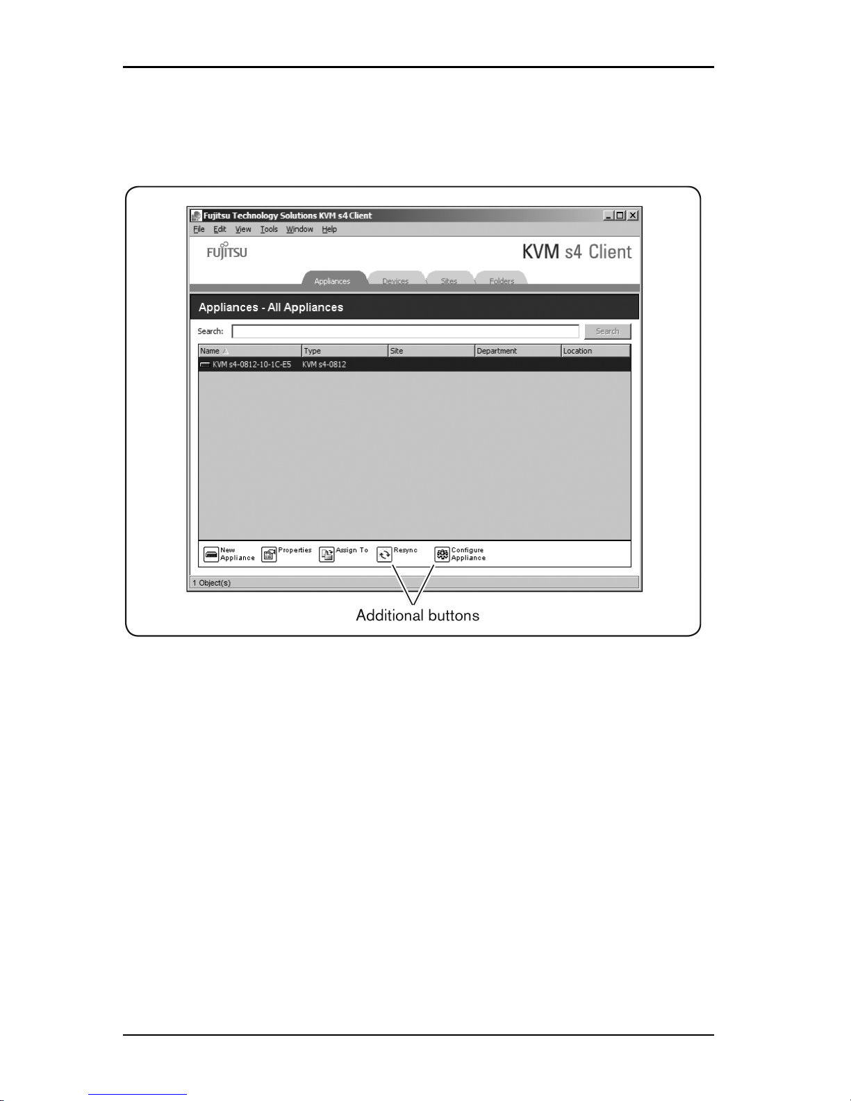
3.3 Customizing the window display
If a selected switch is enabled for the web interface, two additional
buttons appear at the bottom of the Explorer window: Resync and
Configure Appliance.
Figure 3.2. Additional Explorer Buttons When a Switch is Enabled for the Web
Interface
3.3 Customizing the window display
You can resize the Explorer window at any time. Each time you start the
application, the Explorer window opens to its default size and location.
A split-pane divider that runs from top to bottom separates the Group Selector
pane and the Unit Selector pane. You can move the divider left and right to
change the viewing area of these two panes. Each time the Explorer is opened,
the divider returns to its default location. See "Keyboard and mouse shortcuts" on
page 71 for divider pane and tree view control shortcuts.
590-1059-640A
17
Page 24

3. Explorer
You can specify which view (Appliances, Devices, Sites, or Folders) is visible on
startup or you can let the Explorer determine it. For more information, see
"Selected view on startup" on page 30.
You can change the order and sorting of the Unit list by clicking the sort bar
above the column. An upward-pointing arrow in a column header indicates that
the list is sorted by that field name in ascending order. A downward-pointing
arrow indicates the list is sorted by that field name in descending order.
3.4 Adding a switch
Before you can access the switch through the software, you must add it to the
software database. After a switch is added, it is visible in the Unit list. You can
either manually add or discover a switch.
To manually add a switch with an assigned IP address, complete the following
steps:
1. Complete one of the following steps:
• Select File-New-Appliance from the Explorer menu.
• Click the New Appliance button.
The New Appliance Wizard opens. Click Next.
2. Select the type of switch you are adding. Click Next.
3. Click Yes to indicate that the switch has an assigned IP address, then click
Next.
4. Type the IP address and click Next.
5. The software searches for the switch.
The software searches for the indicated unit as well as all the powered
adapter cables and target device names you associated with it in the
local interface, if any.
The Enter Cascade Switch Information window opens if the software
detects an attached cascade switch. This window contains a list of all
ports and adapter cable eIDs (Electronic Identification Numbers)
retrieved from the switch and the tiered switch types to which they are
connected, if any. When this window first opens, all switches are set to
None. Detected switches have an icon next to the pull-down menu.
590-1059-640A
18
Page 25

3.4 Adding a switch
a. The Existing Cascaded Switches field contains all the current cascade
switch types defined in the database. Click Add, Delete, or Modify to
alter the list.
b. Associate the applicable cascaded switch types from the pull-down
menus for each adapter cable that has a cascaded switch attached.
6. When you reach the final page of the Wizard, click Finish to exit the Wizard
and return to the main window. The switch is now included in the Unit list.
To manually add a new switch with no assigned IP address, complete the
following steps:
1. Complete one of the following steps:
• Select File-New-Appliance from the Explorer menu
• Click the New Appliance button.
The New Appliance Wizard opens. Click Next.
2. Click No to indicate that the switch does not have an assigned IP address,
then click Next.
3. The Network Address window opens. Type the IP address, subnet mask (if
using IPv4 mode) or prefix length (if using IPv6 mode), and gateway you
wish to assign to the unit and click Next.
4. The software searches for any switches that do not have assigned IP
addresses. Select the unit to add from the list of new switches that were
found and then click Next.
5. The Configuring Appliance window indicates whether the IP information was
configured. If the configuration is complete, the software searches for the
new switch. Click Next.
The software also searches for all adapter cables and target device
names associated with the switch.
The Enter Cascade Switch Information window opens if the software
detects an attached cascade switch. This window contains a list of all
ports and adapter cable eIDs retrieved from the switch and the cascade
switch types to which they are connected, if any.
a. The Existing Cascaded Switches field contains all the current cascade
switch types defined in the database. Click Add, Delete, or Modify to
alter the list.
590-1059-640A
19
Page 26

3. Explorer
b. Associate the applicable cascade switch type from the pull-down menus
for each adapter cable that has a cascade switch attached.
6. When complete, click Finish to exit the Wizard and return to the main
window. The switch is now included in the Unit list.
To discover and add a switch by IP address, complete the following steps:
1. Select Tools-Discover from the Explorer menu. The Discover Wizard opens.
Click Next.
2. The Address Range page opens. Complete one of the following steps:
• If using IPv4 mode, select Use IPv4 address range. Type the range of IP
addresses you wish to search on the network in the To Address and
From Address boxes. Use IP address dot notation: xxx.xxx.xxx.xxx.
-or-
• If using IPv6 mode, select Use IPv6 subnet, and specify the IPv6 address
and network pre-fix. Use the IPv6 “address/prefix” format.
3. You may also change the default HTTP and HTTPS port numbers, if the
switch has changed from the default on the serial console, by typing the new
port numbers in the HTTP Port and HTTPS Port fields. Click Next to continue.
4. Complete one of the following steps:
• The Searching Network progress window opens. Progress text indicates
how many addresses have been probed from the total number specified
by the range, and the number of switches found (for example, 21 of 100
addresses probed: 3 switches found). If one or more new switches are
discovered, the Wizard shows the Select Appliances to Add page. From
this page, you can select the switches to add to the local database.
-or-
• If no new switches were found (or if you clicked Stop), the Wizard shows
the No New Appliances Found page. You can try entering a different
range to search or add the switches manually.
5. Select one or more switches to add and click the Add (>) icon to move the
selection or selections to the Appliances to Add list. When the Appliances to
Add list contains all the switches you want to add, click Next.
6. The Adding Appliances progress bar window opens. Once all of the switches
have been added to the local database, the Discover Wizard Completed
590-1059-640A
20
Page 27

3.5 Accessing switches
page opens. Click Finish to exit the Wizard and return to the main window.
The new switch is now visible in the Unitlist.
If one or more switches cannot be added to the local database for any
reason, the Discover Wizard Not All Appliances Added page opens. This
page lists all of the switches that you selected and the status for each.
The status indicates if a switch was added to the local database and if
not, why the process failed. Click Done when you are finished reviewing
the list.
If a switch already exists in the database with the same IP address as a
discovered unit, then the discovered unit is ignored and is not listed on the next
Wizard page.
The Discover Wizard does not automatically find target devices attached to the
switch.
3.5 Accessing switches
Clicking the Appliances button opens a list of the switches currently defined in
the localdatabase. The Group Selector pane is visible if two or more switch types
are defined. Click All Appliances or click on a folder to view all switches of a
particular type.
A user name and password prompt opens if this is the first unit access attempt
during the software session. After a unit is accessed, subsequent access attempts
for any unit that uses the same user name and password credentials during this
software session do not require a user name and password. The software
provides credential caching that captures credentials upon first use and
automates the authentication of subsequent unit connections.
To clear login credentials, open the Explorer and go to Tools-Clear Login
Credentials.
To log in to a switch, complete the following steps:
1. Click the Appliances button in the Explorer.
2. Complete one of the following steps:
• Double-click on a switch in the Unit list.
• Highlight the name of a switch. On the web interface, click the Configure
Appliance button.
• Right-click on a switch. A pull-down menu opens. Select either Manage
Appliance or Configure Appliance from the pop-up menu.
590-1059-640A
21
Page 28

3. Explorer
• Select a switch in the list and press Enter.
3. If a user name and password prompt opens, type the user name and
password. [If this is the first switch access since initialization or
reinitialization, the default user name is admin with the password admin.
4. Complete one of the following steps:
• Click OK to access the switch.
• Click Cancel to exit without logging in.
To exit the switch, complete one of the following steps:
• Click OK to save any changes and exit.
• Click Cancel to exit without saving any changes.
3.6 Accessing target devices
Clicking the Devices button opens a list of target devices such as servers, routers,
and other managed equipment that is defined in the local database. The Group
Selector pane is visible if two or more device types are defined. Click All Devices
or click on a folder to view all target devices of a particular type.
A user name and password prompt opens if this is the first unit access attempt
during the software session. After a unit is accessed, subsequent access attempts
for any unit that uses the same user name and password credentials during this
software session do not require a user name and password. The software
provides credential caching that captures credentials upon first use and
automates the authentication of subsequent unit connections.
To clear login credentials, in the Explorer go to Tools-Clear Login Credentials.
When you select a device and click the Connect Video button, the Video Viewer
launches. The Video Viewer allows you full keyboard, video and mouse control
over a device. If a URL has been defined for a given device, then the Browse
button will also be available. The Browse button will launch the configured web
browser, if any, or default browser to the defined URL for that device.
For more information, see "Customizing properties" on page 24 and "Customizing
options" on page 29.
You can also scan through a customized list of devices using the Thumbnail
Viewer. This view contains a series of thumbnail frames, each containing a small,
scaled, non-interactive version of a device screen image. For more information,
see "Using scan mode" on page 51.
To access a target device, complete the following steps:
590-1059-640A
22
Page 29

3.6 Accessing target devices
1. Click the Devices button in the Explorer.
2. Complete one of the following steps:
• Double-click on a target device in the list.
• Select a target device, and then click the connection button: Connect
Video if connected to a switch or Browse if a URL is configured. Only the
applicable button or buttons for the selected target device are visible.
• Right-click on the target device. Select the connection entry from the
pop-up menu: Connect Video for a switch or Browse if a URL is
configured. Only the applicable entry for the selected target device is
visible.
• Select a target device in the Unit list and press Enter.
3. If a browser is used for access, no user name and password prompt opens.
If the Video Viewer is used for access, a user name and password
prompt opens if this is the first access attempt during the software
session.
After a unit is accessed, subsequent access attempts for any unit that
uses the same user name and password credentials during this software
session do not require a user name and password.
The configured access method for that target device opens in a new window.
To search for a target device in the local database:
1. Click the Devices button and insert the cursor in the Search field.
2. Type the search information. This could be a target device name or a
property such as type orlocation.
3. Click the Search button. The results are included in the Unit list.
4. Complete one of the following steps:
• Review the results of the search.
• Click the Clear Results button to open the entire list again.
To auto search by typing in the Devices list:
1. Click the Devices button, then click on any item in the list.
2. Begin typing the first few characters of a target device name. The highlight
moves to the first target device name beginning with those characters. To
590-1059-640A
23
Page 30

3. Explorer
reset the search so you can find another target device, pause for a few
seconds and then type the first few characters of the next target device.
If the target device you are attempting to access is currently being viewed by
another user, and if you have greater privileges than the primary user and
preemption has been configured by an administrator, you can preempt the user
so you can have access to that target device, or request a shared session with
that user. For more information, see "Using preemption" on page 45 and "Using
digital share mode" on page 48.
Launching the VNC or RDP viewer
The Explorer supports user-defined Virtual Network Computing (VNC) and
Remote Desktop Protocol (RDP) viewers. To launch either the VNC or RDP
viewer, select the Server tab from the Explorer. Select a server from the units list,
then click on either the VNC or RDP button at the bottom right of the screen.
3.7 Customizing properties
The Properties window in the Explorer contains the following tabs: General,
Network, Information, if the selected unit is a device, Connections, and for viewer
applications, VNC and RDP. Use these tabs to view and change properties for
the selected unit.
General properties
In General Properties, you can specify a unit Name, Type (target device only),
Icon, Site, Department, and Location. (To customize the Site, Department, and
Location field labels, see "Custom field names" on page 30.)
To view or change general properties:
1. Select a unit in the Unit list.
2. Complete one of the following steps:
• Select View-Properties from the Explorer menu.
• Click the Properties button.
• Right-click on the unit. Select Properties from the pop-up menu.
• The General Properties window opens.
3. In the Name field, type a 1 to 32 character unique name. (This name is local
to the software database; the switch database might contain a different name
for this unit.)
590-1059-640A
24
Page 31

3.7 Customizing properties
4. The Type field is read-only for switches. For a target device, select a type
from the pull-down menu or enter a 1 to 32 character type in the text field.
5. In the Icon field, select an icon from the pull-down menu.
6. In the Site, Department, and Location fields, select an entry from the pulldown menu or enter a 1 to 32 character Site, Department, or Location in the
corresponding text field.
7. Complete one of the following steps:
• Click another tab to change additional properties.
• If finished, click OK to save the new settings.
• Click Cancel to exit without saving the new settings.
Network properties
For a switch, network properties include the address of the switch.
For a target device, network properties specify the URL to use when establishing
a browser connection to the target device. When this field contains a value, the
Browse button is visible in the Explorer task bar.
To view or change network properties:
1. Select a unit in the Unit list.
2. Complete one of the following steps:
• Select View-Properties from the Explorer menu.
• Click the Properties button.
• Right-click on the unit. Select Properties from the pop-up menu.
The Properties window opens.
3. Click the Network tab.
4. In the Address field (switches only), enter the switch address in IP dot
notation or 1 to 128 character host name. You may use either an IPv4 or an
IPv6 address. The address cannot be blank, a loopback address, all zeros or
a duplicate address.
5. In the Browser URL field (devices only), enter a 1 to 256 character URL for
establishing a browserconnection.
590-1059-640A
25
Page 32

3. Explorer
6. Type the HTTP and HTTPS port numbers in the HTTP Port and HTTPS Port
fields, respectively, if the port numbers were changed for the switch in the
serial console.
7. Complete one of the following steps:
• Click another tab to change additional properties.
• If finished, click OK to save the new settings.
• Click Cancel to exit without saving the new settings.
Information properties
Information properties include description, contact phone number, and comment
information. You can use these fields to store any information you require.
To view or change information properties:
1. Select a unit in the Unit list.
2. Complete one of the following steps:
• Select View-Properties from the Explorer menu.
• Click the Properties button.
• Right-click on the unit. Select Properties from the pop-up menu.
The Properties window opens.
3. Click the Information tab. You can enter any information in the following
fields.
a. In the Description field, enter 0 to 128 characters.
b. In the Contact field, enter 0 to 128 characters.
c. In the Contact Phone Number field, enter 0 to 64 characters.
d. In the Comment field, enter 0 to 256 characters.
4. Complete one of the following steps:
• Click another tab to change additional properties.
• If finished, click OK to save the new settings.
• Click Cancel to exit without saving the new settings.
Connections properties
Connections properties are available only for target devices and are read-only.
The display indicates the physical connection path that is used to access this
590-1059-640A
26
Page 33

3.7 Customizing properties
target device and the connection type, such as video.
To view connections properties:
1. Select a target device in the Unit list.
2. Complete one of the following steps:
• Select View-Properties from the Explorer menu.
• Click the Properties button.
• Right-click on the unit. Select Properties from the pop-up menu.
The Properties window opens.
3. Click the Connections tab to view the connections of the server. Connections
properties are available only for servers and are read-only. The display
indicates the physical connection path that is used to access this device and
the connection type, such as video.
4. When finished, click OK or Cancel to close the window.
VNC Properties
When you indicate a user-specified VNC application, you may include its
command line arguments. A selection of macros is available for placement in the
command line; this may be useful for automatic replacement of variables such as
IP address, port number, user name and password. For VNC commands that do
not provide their own GUI, such as those for computers running Windows, Linux
and Unix® operating systems, you can launch the VNC application from within an
OS command window.
To change VNC properties:
1. Select a switch or server in the unit list.
2. Select View-Properties from the Explorer.
— or —
Click the Properties task button.
— or —
Right-click on the unit. Select Properties from the pop-up menu.
The Properties dialog box appears.
3. Click the VNC tab.
590-1059-640A
27
Page 34

3. Explorer
4. For servers only, in the IP Address field, enter an IP address in dot notation
or a 1-128 character domain name. You may use either an IPv4 or IPv6 IP
address. Duplicate addresses are allowed. Spaces are not allowed.
5. In the Port field, enter a port number in the range 23-65535. If blank, port 23
is used.
6. Enable or disable the Use Default check box. When this setting is enabled,
the default global setting specified in Options will be used and all other
portions of the VNC Application to Launch area are disabled.
7. Enter the directory path and name or click the Browse button to locate the
path and name.
8. Enter command line arguments in the box below the path and name.
— or —
To insert a predefined macro at the cursor location in the command line,
click the Insert Macro list box and select a macro from the drop-down
menu. The Explorer will automatically replace these variables when the
application runs.
9. Enable or disable the Launch in command window check box. When
enabled, the user-specified VNC application will be launched from within an
OS command window.
10. Complete one of the following steps:
• Click another tab to change additional properties.
• If finished, click OK to save the new settings.
• Click Cancel to exit without saving the new settings.
RDP Properties
When you indicate a user-specified RDP application, you may include its
command line arguments. A selection of macros is available for placement in the
command line; this may be useful for automatic replacement of variables such as
IP address, port number, user name and password. For RDP commands that do
not provide their own GUI, such as those for computers running Windows, Linux
and Unix operating systems, you can launch the RDP application from within an
OS command window.
To change RDP properties:
1. Select a switch or server in the unit list.
2. Select View-Properties from the Explorer.
590-1059-640A
28
Page 35

3.8 Customizing options
— or —
Click the Properties task button.
— or —
Right-click on the unit. Select Properties from the pop-up menu.
The Properties dialog box appears.
3. Click the RDP tab.
4. For servers only, in the IP Address field, enter an IP address in dot notation
or enter a 1-128 character domain name. You may use either an IPv4 or IPv6
IP address. Duplicate addresses are allowed. Spaces are not allowed.
5. In the Port field, enter a port number in the range 23-65535. If blank, port 23
is used.
6. Enable or disable the Use Default check box. When enabled, the default
global setting specified in Options will be used and all other portions of the
RDP Application to Launch area are disabled.
7. Enter the directory path and name or click the Browse button to locate the
path and name.
8. Enter command line arguments in the box below the path and name.
— or —
To insert a predefined macro at the cursor location in the command line,
click the Insert Macro list box and select a macro from the drop-down
menu. The Explorer will automatically replace these variables when the
application runs.
9. Enable or disable the Launch in command window check box. When
enabled, the user-specified RDP application will be launched from within an
OS command window.
10. Complete one of the following steps:
• Click another tab to change additional properties.
• If finished, click OK to save the new settings.
• Click Cancel to exit without saving the new settings.
3.8 Customizing options
Set general options for the Explorer in the Options window. General options
include custom field names, selected view on startup, browser application, and
590-1059-640A
29
Page 36

3. Explorer
DirectDraw support. You can customize options for the Explorer, including
custom name fields, default view, and default browser.
Custom field names
In the Custom field labels area, you can change the Site, Department, and
Location headings that are visible in the Group and Unit Selector panes. You can
group units in ways that are meaningful to you. The Department field is a subset
of Site.
To change custom field names:
1. Select Tools-Options from the Explorer menu. The General Options window
opens.
2. In the Custom field labels area, select a field label to modify and click the
Modify button. The Modify Custom Field Label window opens. Remember
that the Department field is a subset of the Site field, even if it is renamed.
Type the 1 to 32 character singular and plural versions of the new field label.
You can use embedded spaces but not leading or trailing spaces. You
cannot use blank field labels.
3. Click OK to save the settings or Cancel to exit without saving the assignment.
Selected view on startup
The Selected view on startup option specifies the view that is visible when the
software opens, either Appliances, Devices, Sites, or Folders. You can select a
view or let the Explorer determine the view. When you let the Explorer determine
the view, the Devices view is visible if you have one or more target devices
defined. If you do not, the Appliances view is visible.
To view or change the selected view on startup:
1. Select Tools-Options from the Explorer menu. The General Options window
opens.
2. Complete one of the following steps:
• If you want the Explorer to determine the best view on startup, select the
Default check box.
• If you want to specify which view opens on startup, clear the Default
check box and select Appliances, Devices, Sites, or Folders from the
pull-down menu.
3. Complete one of the following steps:
• Click another tab to change additional properties.
590-1059-640A
30
Page 37

3.8 Customizing options
• If finished, click OK to save the new settings.
• Click Cancel to exit without saving the new settings.
Default browser
The Browser option specifies the browser application that opens when you click
the Browse button for a target device that has URL defined, or when the
software's online help is opened. You can either enable the default browser
application of the current computer or select among other availablebrowsers.
To view or change the default browser:
1. Select Tools-Options from the Explorer menu. The General Options window
opens.
2. Complete one of the following steps:
• In the Browser field, select the Launch Default Browser check box to
specify the default browser.
• Clear the Launch Default Browser check box. Click the Browse button
and select a browser executable on the computer. You can also enter
the full path name of the browserexecutable.
3. Complete one of the following steps:
• Click another tab to change additional properties.
• If finished, click OK to save the new settings.
• Click Cancel to exit without saving the new settings.
DirectDraw support (Windows only)
The DirectDraw option affects operation of the Video Viewer when running on
Windows operating systems. The software supports DirectDraw, a standard that
you can use to directly manipulate video display memory, hardware blitting,
hardware overlays, and page flipping without the intervention of the Graphical
Device Interface (GDI). This can result in smoother animation and improvement in
the performance of display-intensive software.
However, if the machine has a software cursor or pointer shadow enabled, or if
the video driver does not support DirectDraw, you can experience a flicker in the
mouse cursor when over the title bar of the Video Viewer. You can either disable
the software cursor or pointer shadow, load a new target device driver for the
video card, or disable DirectDraw.
590-1059-640A
31
Page 38

3. Explorer
To view or change DirectDraw support:
1. Select Tools-Options from the Explorer menu. The General Options window
opens.
2. In the DirectDraw field, select or clear the DirectDraw check box.
3. Complete one of the following steps:
• Click another tab to change additional properties.
• If finished, click OK to save the new settings.
• Click Cancel to exit without saving the new settings.
HTTP/HTTPS options
The switch and the Explorer use port 80 as the default HTTP port and port 443 as
the default HTTPS port. You can change the default port numbers used in the
HTTP/HTTPS Ports tab of the Options dialog box.
To change HTTP/HTTPS options:
1. Select Tools-Options from the Explorer menu. The Options dialog box
appears.
2. Click the HTTP/HTTPS Ports tab.
3. Enter the appropriate ports in the HTTP Port and HTTPS Port fields.
4. Complete one of the following steps:
• Click another tab to change additional properties.
• If finished, click OK to save the new settings.
• Click Cancel to exit without saving the new settings.
VNC options
The Explorer supports a user-defined VNC viewer through the properties page. In
the VNC tab you can search for a user-specific VNC application and include its
command line arguments. A selection of macros is available for placement in the
command line; this may be useful for automatic replacement of variables such as
IP address, port number, user name and password. For VNC commands that do
not provide their own GUI, such as those for computers running standard
Windows, Linux and Unix operating systems, you may have the VNC application
launch from within an OS command window.
590-1059-640A
32
Page 39

3.8 Customizing options
The switch will attempt to detect if Java is already installed on your PC. If itisnot, in
order to use the web interface, download the latest version of JavaRuntime
Environment from http://www.java.com and associate the JNLP file with Java
WebStart.
To change VNC options:
1. Select Tools-Options from the Explorer. The Options dialog box appears.
2. Click the VNC tab.
3. In the VNC Application to Launch field, enter the directory path and name or
click the Browse button to locate the path and name.
4. Enter command line arguments in the box below the path and name.
— or —
To insert a predefined macro at the cursor location in the command line,
click the Insert Macro list box and select a macro from the drop-down
menu. The Explorer will automatically replace these variables when the
application runs.
5. Enable or disable the Launch in command window by marking or clearing
the check box. When enabled, the user-specified VNC application will be
launched from within an OS command window.
6. Complete one of the following steps:
• Click another tab to change additional properties.
• If finished, click OK to save the new settings.
• Click Cancel to exit without saving the new settings.
RDP options
The Explorer supports a user-defined RDP viewer through the properties page. In
the RDP tab you can search for a user-specific RDP application and you may
include its command line arguments. A selection of macros is available for
placement in the command line; this may be useful for automatic replacement of
variables such as IP address, port number, user name and password. For RDP
commands that do not provide their own GUI, such as those for computers
running Windows, Linux and Unix operating systems, you can launch the RDP
application from within an OS command window.
590-1059-640A
33
Page 40

3. Explorer
The switch will attempt to detect if Java is already installed on your PC. If itisnot, in
order to use the web interface, download the latest version of JavaRuntime
Environment from http://www.java.com and associate the JNLP file with Java
WebStart.
To change RDP options:
1. Select Tools-Options from the Explorer. The Options dialog box appears.
2. Click the RDP tab.
3. In the RDP Application to Launch field, enter the directory path and name or
click the Browse button to locate the path and name.
4. Enter command line arguments in the box below the path and name.
— or —
To insert a predefined macro at the cursor location in the command line,
click the Insert Macro list box and select a macro from the drop-down
menu. The Explorer will automatically replace these variables when the
application runs.
5. Enable or disable the Launch in command window by marking or clearing
the check box. When enabled, the user-specified RDP application will be
launched from within an OS command window.
6. Complete one of the following steps:
• Click another tab to change additional properties.
• If finished, click OK to save the new settings.
• Click Cancel to exit without saving the new settings.
3.9 Managing folders
Use folders to create a customized organizational system for groups of units. For
example, you might create a folder for critical target devices or for remote target
devices. Folders are listed under the Folders button in the Explorer. You can
name and structure folders in any way youchoose.
To create a folder, complete the following steps:
1. Select the Folders button.
2. Complete one of the following steps:
• Click on the top-level Folders node and select File-New-Folder.
590-1059-640A
34
Page 41

3.10 Assigning units
• To create a nested folder, click on an existing folder and select FileNew-Folder in the Explorer menu. The New Folder window opens.
3. Type a 1 to 32 character name. Folder names are not case sensitive. You
can use embedded spaces but not leading or trailing spaces. You cannot
use duplicate folder names at the same level, but you can use duplicate
folder names on different levels.
4. Click OK. The new folder is listed in the Group Selector pane.
To assign a unit to a folder, see "Assigning units" on page 35. To rename or
delete a folder, see "Renaming" on page 37 and "Deleting" on page 36.
3.10 Assigning units
After you have created a new Site, Location, or Folder, you can assign a unit to
that organization. The Assign menu item is only enabled when a single unit is
selected in the Unit list (the custom assignment targets are defined in the General
Properties window).
There are three ways to assign a unit to a Site, Location, or Folder: editing the
unit Properties window, using the Assign function, or dragging and dropping.
To assign a unit to a Site, Location, or Folder using the Properties window:
1. Select a unit in the Unit list.
2. Complete one of the following steps:
• Select View-Properties from the Explorer menu.
• Click the Properties button. The Properties window opens.
3. Click the General tab. Select the Site, Department, or Location to which you
want to assign the unit.
4. Complete one of the following steps:
• Click OK to save the assignment.
• Click Cancel to exit without saving the assignment.
To assign a unit to a Site, Location, or Folder using the Assign function:
1. Select a unit in the Unit list.
2. Complete one of the following steps:
• Select Edit-Assign from the Explorer menu.
• Click the Assign To button.
590-1059-640A
35
Page 42

3. Explorer
• Right-click on a unit and select Assign To from the pop-up menu.
The Assign To window opens.
3. In the Category pull-down menu, select Site, Location, or Folder.
4. In the Target list, select the assignment you want to designate. The target list
is empty if no Site, Location, or Folder has been defined in the local
database.
5. Complete one of the following steps:
• Click OK to save the assignment.
• Click Cancel to exit without saving the assignment.
To assign a unit to a Site, Location, or Folder using drag and drop:
1. To use drag and drop, click and hold on a unit in the Unit list.
2. Drag the item on top of a folder icon (node) in the tree view of the Group
Selector pane. Release the mouse button.
3. The item is now visible in the Unit list when you click that node.
A unit cannot be moved to All Departments, All Units, or the root Sites node. Units
can only be moved one at a time.
3.11 Deleting
The delete function works according to what is currently selected in the Group
and Unit Selector panes. When you select and delete a unit in the Unit list, it is
removed from the local database. When you select and delete an item in the tree
view of the Group Selector pane, you can delete Server Types, Sites,
Departments, or Folders; however, none of the actions result in units being
deleted from the local database.
To delete a unit:
1. Select the unit or units to delete from the Unit list.
2. Complete one of the following steps:
• Select Edit-Delete from the Explorer menu.
• Right-click on a unit and select Delete from the pop-up menu.
• Press the Delete key on the keyboard.
3. A window prompts you to confirm the number of units you want to delete. If
you are deleting a switch, the window includes a Delete Associated Devices
590-1059-640A
36
Page 43

3.12 Renaming
check box. Select or clear the check box as needed. If you do not delete the
associated target devices, they are still visible in the target devices list but
you cannot connect to them unless they have a URL assigned, in which case
you can connect to the target device using a browser.
4. Complete one of the following steps:
• Click Yes to confirm the deletion. You might receive additional message
prompts, depending on the configuration. Respond as needed. The
units are deleted.
• Click No to cancel the deletion.
To delete a target device Type, Site, Department, or Folder:
1. Select the target device Type, Site, Department, or Folder to delete from the
Group Selector pane.
2. Complete one of the following steps:
• Select Edit-Delete from the Explorer menu.
• Press the Delete key on the keyboard.
3. You are prompted to confirm the number of units that are affected by this
deletion. Complete one of the following steps:
• Click Yes to confirm the deletion. You might receive additional message
prompts, depending on the configuration. Respond as needed. The
element is deleted.
• Click No to cancel the deletion.
3.12 Renaming
The rename function works according to what is currently selected. You might
select and rename a switch or a target device from the Unit list. You can select
and rename unit Types, Sites, Departments, and Folder names in the tree view of
the Group Selector pane.
To rename a unit Type, Site, Department, or Folder:
1. Complete one of the following steps:
• Select a unit from the Unit list.
• In the Group Selector pane, select the unit Type, Site, Department, or
Folder torename.
2. Complete one of the following steps:
590-1059-640A
37
Page 44

3. Explorer
• Select Edit-Rename from the Explorer menu.
• Right-click on the unit Type, Site, Department, or Folder in the Unit list
and select Rename from the pop-up menu. The Rename window opens.
3. Type a 1 to 32 character name. You can use embedded spaces but not
leading or trailing spaces. (This name is local to the software database; the
switch database might contain a different name for this unit.)
4. Complete one of the following steps:
• Click OK to save the new name.
• Click Cancel to exit without saving changes.
For a unit Type, Site, Department, or Folder, you cannot use duplicate names,
including the same name with different cases, with two exceptions: department
names can be duplicated on different sites and folder names can be duplicated
on different levels.
3.13 Managing the software database
Each computer running the software contains a local database that records the
information that you enter about the units. If you have multiple computers, you
can configure one computer and then save a copy of this database and load it
into the other computers to avoid unnecessarily reconfiguring each computer.
You can also export the database for use in another application.
Saving and loading a database
You can save a copy of the local database and then load it back to the same
computer where it was created, or onto another computer running the software.
The saved database is compressed into a single Zip file.
While the database is being saved or loaded, you cannot use or modify the
database. You must close all other windows, including target device session
windows. If other windows are open, a message prompts you to either continue
and close all open windows or quit and cancel the database save process.
To save a database:
1. Select File-Database-Save from the Explorer menu. The Database Save
window opens.
2. Enter a file name and select a location to save the file.
590-1059-640A
38
Page 45

3.13 Managing the software database
3. Click Save. A progress bar is visible during the save. When finished, a
message indicates that the save is complete and you are returned to the
main window.
To load a database:
1. Select File-Database-Load from the Explorer menu. The Database Load
window opens.
2. Browse to select a database to load.
3. Click Load. A progress bar is visible during the load. When finished, a
message indicates that the load is complete, and you are returned to the
main window.
Exporting a database
You can export fields from the local database to a Comma Separated Value
(CSV) file or Tab Separated Value (TSV) file. The following database fields are
exported:
Appliance flag Type Name
Address Custom Field 1 Custom Field 2
Custom Field 3 Description Contact Name
Contact Phone Comments Browser URL
The first line of the exported file contains the column names for the field data.
Each additional line contains the field data for a unit. The file contains a line for
each unit defined in the local database.
To export a database:
1. Select File-Database-Export from the Explorer menu. The Database Export
window opens.
2. Type a file name and browse to the location to save the exported file.
3. Click Export. A progress bar is visible during the export. When finished, a
message indicates that the export is complete, and you are returned to the
main window.
590-1059-640A
39
Page 46

3. Explorer
590-1059-640A
40
Page 47

4. Video Viewer
4.1 About the Video Viewer
The Video Viewer is used for connecting to target devices on KVM s4 switches.
When you connect to a target device using the KVMs4 client software, the
desktop of the device is visible in a separate Video Viewer window. You can see
both the local cursor and the target device cursor. You can select the Toolbar
Align local cursor button to enable a single cursor mode, so that only the target
device cursor is visible.
From the viewer window, you can access all the normal functions of the target
device as if you were sitting in front of it. You can also perform viewer-specific
tasks such as sending macro commands to the target device.
If the target device you are attempting to access is currently being viewed by
another user, you can be presented with session sharing options depending on
how the administrator has configured KVM sessions and depending on your
access rights.
Session sharing options
Session sharing can be configured by Admin and other users with Appliance
Administrator or User Administrator rights. The first user with a KVM session with
a target device is called the primary user. If another (secondary) user attempts to
start a KVM session with the same target device, options for the secondary user
depend on the following two conditions:
• The access rights of the two users
• Whether an administrator has configured global connection sharing
Automatic Sharing, Exclusive Connections, and Stealth Connections all
are configurable options that require connection sharing to be enabled.
Term Definition
Automatic
Sharing
Secondary users can share a KVM session without first requesting
permission from primary users.
Exclusive
Connection
Primary users can designate a KVM session as an exclusive
connection that cannot be shared.
Table 4.1: Session sharing definitions
590-1059-640A
41
Page 48
4. Video Viewer
Term Definition
Stealth
Connection
A stealth connection allows undetected viewing of KVM sessions. A
secondary user with Appliance Administrator rights can create a
stealth connection to any KVM session. A secondary user with User
Administrator rights can create a stealth connection when the access
rights of the secondary user are the same asor higher than the rights
of the primary user. Stealth permissionsfollow preemption
permissions.
Preempt mode
A secondary user with Appliance Administrator rights can preempt a
session. a secondary user with User Administrator rights can preempt
a session onlywhen the accessrights of the secondary user are the
same as or higher than the rights of the primary user.
If you are an administrator, you can share a KVM session and preempt the
session. If session sharing and stealth connections are enabled, an administrator
can observe the session in stealth mode. For more information about access
rights and session types, see "Video session indicators in the toolbar" on page
44.
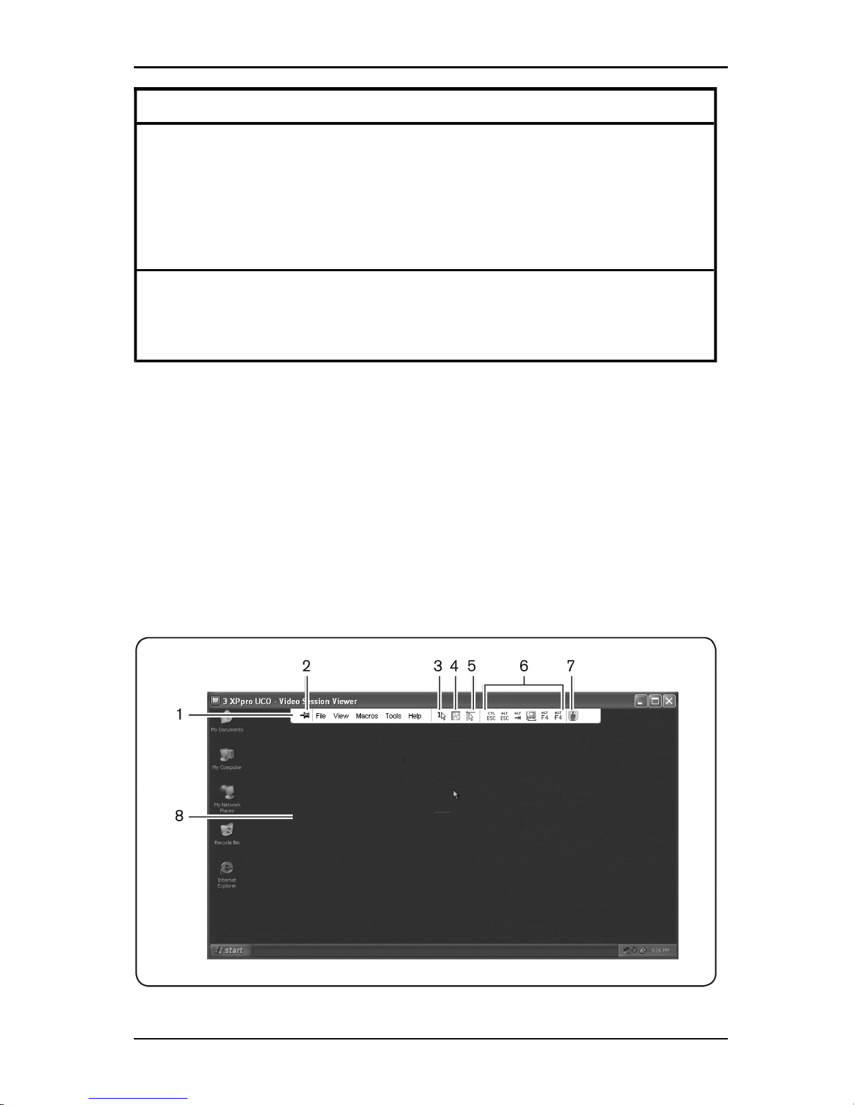
Video Viewer window
The following figure shows a Video Viewer window and the default arrangement
of buttons on the toolbar. (The arrangement and the types of buttons are user
configurable.)
590-1059-640A
42
Page 49

4.1 About the Video Viewer
Figure 4.1. Video Viewer Window
Callout Description
1 Menu and toolbar.
2
Thumbtack icon: When the thumbtack is locked, the toolbar isvisible.
When the thumbtack is unlocked, the toolbar isvisible onlywhen the mouse
hovers over it.
3
Single Cursor Mode button: Hides the localcursor and displaysonly
the target device cursor. Useful when administrators do not to reset mouse
acceleration on each target device.
4 Refresh Video button.
5
Align Local Cursor button: Re-establishes tracking of the local cursor
to the target device cursor.
6 User-selected buttons and macro commands.
7 Connection Status indicator.
8 Target device desktop.
Table 4.2: Video Viewer Window Areas
To access the Video Viewer:
1. Click the Devices button in the Explorer.
2. Complete one of the following steps:
• Double-click on the target device in the Unit list.
• Select the target device, then click the Connect Video button.
• Right-click on the target device. Select Connect Video from the pop-up
menu.
• Select the target device and press Enter.
If the target device is not being viewed by another user, the Video
Viewer opens in a new window. If the target device is being accessed by
another user, you can have the option to preempt the session, share the
session, or observe the session in stealth mode, depending on session
sharing configuration and your access rights.
If you are not currently logged into the target device, a login prompt
appears.
3. Log in if needed.
590-1059-640A
43
Page 50

4. Video Viewer
Important: A user name and password are not required for any subsequent
access attempts if you do not log out, unless the system times you out.
To close a Video Viewer session, complete one of the following steps:
• Select File-Exit from the Video Viewer menu.
• Click X to close the Video Viewer session.
Video session indicators in the toolbar
The current type of session is indicated by an icon on the right side of the Video
Viewer toolbar.
Session types Icons Description
Active (normal)
A normal KVM session that isnot exclusive and isnot
being shared.
Locked (normal)
A normal KVM session and a VM session locked
together.The administrator has configured lockingof
KVM and Virtual Media (VM) sessions. The KVM
session cannot be shared or preempted, and it is not
subject to inactivitytimeout. It can be terminated by an
administrator. For more information, see "Using
virtual media" on page 60.
Exclusive
An exclusive KVM session that cannot be shared. It
can be preempted or observed in stealth mode by an
administrator.
Active sharing:
(primary)
A shared KVM session whose user is the first
(primary) user to connect to the target device. The
session is being shared with a secondary user or
users.
Active sharing:
(secondary)
A shared KVM session whose user is a secondary
user.
Passive sharing
A shared KVM session whose secondary user can
view the video ouput, but who isnot allowed keyboard
and mouse control over the target device.
Table 4.3: Video Session Type Icons
590-1059-640A
44
Page 51
4.2 Using preemption
Session types Icons Description
Stealth
A KVM session in which the secondary user isable to
view the video output of the target device without the
permission or knowledge of the primary user. The
user cannot have keyboard and mouse control over
the target device. Available for administrators only.
Scanning
A session during whichthe current user is able to
monitor up to 16 target devices in thumbnailview. No
status indicator icon isvisible when in scan mode.
4.2 Using preemption
Secondary users with administrator access rights that are equal to or greater than
those of the primary user rights can preempt a KVM session, if an administrator
has enabled session preemption.
All users sharing the session that is being preempted are warned, unless the
target device is connected to an RCM switch. A primary user with administrator
access rights that are equal to those of the secondary user can reject the
preemption.
4.2 outlines the preemption scenarios and detailed scenarios in which
preemption requests can be rejected.
Current user Preempted by Preemption can be rejected
User Local user No
User User administrator No
User
Appliance
administrator
No
Appliance
administrator
Local user Yes
Appliance
administrator
Appliance
administrator
Yes
User administrator Local user No
User administrator User administrator Yes
Table 4.4: Preemption scenarios
590-1059-640A
45
Page 52

4. Video Viewer
Current user Preempted by Preemption can be rejected
User administrator
Appliance
administrator
No
Local user User administrator Yes
Local user
Appliance
administrator
Yes
Preemption of a user by an administrator
If an administrator attempts to access a target device that is being accessed by a
user, a message requests that the administrator wait while the user is informed
that their session will be preempted. The user cannot reject the preemption
request and will be disconnected. The time period given before disconnection is
defined by the Video session preemption timeout setting in the Global-Sessions
category.
Preemption of a local user/administrator by an administrator
If an administrator attempts to access a target device that is being accessed by
the local user or by another administrator with equal privileges, the currently
connected user can accept or reject the preemption request. A message asks the
connected local user or administrator whether they want to accept the preemption
request. If the preemption request is rejected, a message is displayed informing
the administrator that their request has been rejected and that they cannot access
the target device.
In scenarios where a preemption request can be rejected, the Session
Preemption Request window opens. Use this window to accept the preemption
request by clicking the Accept button, or reject the preemption request by clicking
the Reject button or by closing the window.
To preempt the current user:
1. Click the Devices button in the Explorer.
2. Complete one of the following steps:
• Double-click on the target device in the Unit list.
• Select the target device, then click the Connect Video button.
• Right-click on the target device. Select Connect Video from the pop-up
menu.
• Select the target device and press Enter.
590-1059-640A
46
Page 53

4.3 Using exclusive mode
When another user is viewing this target device, a message indicates
that the target device is already involved in a KVM session.
If the switch has connection sharing enabled, you are given the option to
share the session. For information about connection sharing, see "Using
preemption" on page 45. If your access rights (as compared with those
of the primary user) allow it, you are prompted to either share or preempt
the existing session.
3. If the option is available, select Preempt.
4. Complete one of the following steps:
• Click OK or Yes. A preemption notification is sent to the primary user.
Depending on your access rights, the primary user might be able to
reject the preemption.
• Click No to let the primary user retain the connection.
5. If the preemption completes, the Video Viewer of the target device session
opens.
4.3 Using exclusive mode
If session sharing and exclusive connections are enabled, you can create an
exclusive KVM session. When operating a session in exclusive mode, you cannot
receive any share requests from other users. However, administrators can
choose to preempt (or terminate) the session or monitor the session in stealth
mode.
To enable exclusive KVM sessions on a switch:
1. Click the Appliances button in the Explorer.
2. Complete one of the following steps:
• Double-click on a KVM s4 switch in the Unit list.
• Select a KVMs4 switch from the Unit list, then click the Manage
Appliance button.
• Right-click on a KVMs4 switch in the Unit list. Select Manage Appliance
from the pop-up menu.
• Select a KVMs4 switch in the Unit list and press Enter.
3. Select the Global-Sessions subcategory.
4. Select the Enable Shared Sessions check box in the Connection Sharing
area.
590-1059-640A
47
Page 54

4. Video Viewer
5. Select Exclusive Connections in the Connection Sharing area.
Only the primary user of a shared connection or the only user of a non-shared
session can access the Video Viewer in exclusive mode.
To access the Video Viewer in exclusive mode:
1. Open a KVM session to a target device.
2. Select Tools-Exclusive Mode from the Video Viewer toolbar.
3. If the KVM session is currently shared, only the primary user can designate
the session as exclusive. A message warns the primary user that secondary
sessions will be terminated if an exclusive session is invoked.
Complete one of the following steps:
• Select Yes to terminate the sessions of the secondary users.
• Select No to cancel the exclusive mode action.
Secondary users cannot share the exclusive KVM session. However,
administrators or users with certain access rights can still terminate the session.
4.4 Using digital share mode
Multiple users can view and interact with a target device using digital share
mode. When a session is shared, the secondary user can be an active user with
keyboard and mouse control or a passive user that does not have keyboard and
mouse control.
To configure a switch to share KVM sessions:
1. Click the Appliances button in the Explorer.
2. Complete one of the following steps:
• Double-click on a KVM s4 switch in the Unit list.
• Select a KVMs4 switch from the Unit list, then click the Manage
Appliance button.
• Right-click on a KVMs4 switch in the Unit list. Select Manage Appliance
from the pop-up menu.
• Select a KVMs4 switch in the Unit list and press Enter.
3. Select the Global-Sessions subcategory.
4. Select Enable Share Mode in the Connection Sharing area.
590-1059-640A
48
Page 55

4.4 Using digital share mode
5. You can choose to select Automatic Sharing. This enables secondary users
to automatically share a KVM session without first requesting permission
from the primary user.
To share a digital connection, complete the following steps:
1. Click the Devices button in the Explorer.
2. Complete one of the following steps:
• Double-click on the target device in the Unit list.
• Select the target device, then click the Connect Video button.
• Right-click on the target device. Select Connect Video from the pop-up
menu.
• Select the target device and press Enter.
When another user is viewing this target device, a message indicates
that the target device is already involved in a KVM session.
If connection sharing is enabled on the switch and your access rights (as
compared with those of the primary user) allow it, you are prompted to
either share or preempt the existing session.
3. If the option is available, select Share.
4. Complete one of the following steps:
• Click OK or Yes. If Automatic Sharing is not enabled, a share request is
sent to the primary user, who can accept the share request as either an
active or passive (read-only) session, or reject the share request
entirely.
• Click No to cancel the share request.
If the primary user accepts the share request, or if Automatic Sharing is enabled,
a KVM session to the target device session opens, and the session type icon
within the new Video Viewer window indicates if the session status is active or
passive. If the request is rejected, a message indicates that the request was
denied. Administrators have several options at this point. They can either try to
connect again and preempt the session or connect in stealth mode, or they can
terminate the session entirely.
If you are not prompted to connect in share mode, either the switch to which the
target device is connected is not configured to allow digital share mode sessions
or it is not a KVM s4 switch.
590-1059-640A
49
Page 56

4. Video Viewer
4.5 Using stealth mode
Administrators can connect to a target device in stealth mode to view the video
output of a remote user undetected. When in stealth mode, the administrator does
not have keyboard or mouse control over the target device.
To enable stealth KVM sessions on a switch:
1. Click the Appliances button in the Explorer.
2. Complete one of the following steps:
• Double-click on a KVM s4 switch in the Unit list.
• Select a KVMs4 switch from the Unit list, then click the Manage
Appliance button.
• Right-click on a KVMs4 switch in the Unit list. Select Manage Appliance
from the pop-up menu.
• Select a KVMs4 switch in the Unit list and press Enter.
3. Select the Global-Sessions subcategory.
4. Select Stealth Connections in the Connection Sharing area.
To monitor a target device in stealth mode:
1. Click the Devices button in the Explorer.
2. Complete one of the following steps:
• Double-click on the target device in the Unit list.
• Select the target device, then click the Connect Video button.
• Right-click on the target device. Select Connect Video from the pop-up
menu.
• Select the target device and press Enter.
3. If another user is already viewing this target device, a message indicates that
the target device is already involved in a KVM session.
If connection sharing and stealth connections are enabled on the switch
and your access rights (as compared with those of the primary user)
allow it, you are prompted to either share or preempt the existing
session. If the option is available, select Stealth.
4. Complete one of the following steps:
• Click OK or Yes.
590-1059-640A
50
Page 57

4.6 Using scan mode
• Click No to cancel the stealth request.
A KVM session to the target device opens, and the administrator can view all
video output of the target device while remaining undetected.
If Stealth is not listed as an option, one of the following conditions exist:
• the switch to which the target device is connected is not configured to allow
Stealth Connections
• you do not have the necessary access rights (Stealth permissions follow
Preemption permissions)
• the switch the target device is connected to is not a KVM s4 switch
4.6 Using scan mode
You can view multiple target devices using the scan mode Thumbnail Viewer.
This view contains a series of thumbnail frames, each containing a small, scaled,
non-interactive version of a target device screen image. The target device name
and status indicator are visible below each thumbnail as follows:
• A green circle icon indicates that a target device is currently being scanned.
• A red X icon indicates that the last scan of the target device failed. The scan
can have failed due to a credential or path failure (for example, the target
device path on the switch was not available). The tool tip for the icon
indicates the reason for the failure.
You can set up a scan sequence of up to 16 target devices to monitor. The scan
mode moves from one thumbnail image to the next, logging into a target device
and displaying an updated target device image for a specified length of time
(View Time Per Server), before logging out of that target device and moving on to
the next thumbnail image. You can also specify a scan delay between thumbnails
(Time Between Servers). During the delay, you can see the last thumbnail image
for all target devices in the scan sequence, but you won’t be logged into any
target devices.
When you first open the Thumbnail Viewer, each frame is filled with a black
background until a target device image is visible. An indicator icon at the bottom
of each frame displays the target device status. The default thumbnail size is
based on the number of target devices in the scan list.
Scan mode has a lower priority than an active connection. If a user is connected
to a target device, that target device is skipped in the scan sequence, and scan
mode proceeds to the next target device. No login error messages are visible.
590-1059-640A
51
Page 58

4. Video Viewer
After the interactive session is closed, the thumbnail is included in the scan
sequence again.
You can disable a target device thumbnail from the scan sequence. The
thumbnail image remains, but it is not updated until it is once again enabled.
Accessing scan mode
To access scan mode:
1. Select the Appliance, Devices, Sites, or Folders button in the Explorer
window.
2. Select two or more target devices in the Unit list by pressing the Shift or
Control key. The Scan Mode button is visible.
3. Click the Scan Mode button. The Thumbnail Viewer window opens.
Setting scan options
To set scan preferences:
1. Select Options-Preferences from the Thumbnail Viewer menu. The
Preferenceswindow opens.
2. In the View Time Per Server field, enter the time each thumbnail is active
during the scan, in the range of 10 to 60 seconds.
3. In the Time Between Servers field, enter the time the scan stops between
each target device, in the range of 5 to 60 seconds.
4. Click OK.
To change the thumbnail size, complete the following steps:
1. Select Options-Thumbnail Size from the Thumbnail Viewer menu.
2. Select a thumbnail size from the cascaded menu.
Managing the scan sequence
To pause or restart a scan sequence:
1. Select Options-Pause Scan from the Thumbnail Viewer menu.
2. The scan sequence pauses at the current thumbnail if the Thumbnail Viewer
has a scan in progress or restarts the scan if currentlypaused.
To disable a target device thumbnail in the scan sequence:
• Select a target device thumbnail. Select Thumbnail-<target device name>Enable from the Thumbnail Viewer menu. (The Enable menu item state can
590-1059-640A
52
Page 59

4.7 Adjusting the view
be toggled from checked (enabled) to unchecked (disabled) each time it is
selected).
• Right-click on a target device thumbnail and select Disable from the pop-up
menu. Updating of that thumbnail image stops until it is enabled again.
To enable a target device thumbnail in the scan sequence:
• Select a target device thumbnail. Select Thumbnail-<target device name>Enable from the Thumbnail Viewer menu. (The Enable menu item state can
be toggled from checked (enabled) to unchecked (disabled) each time it is
selected).
• Right-click on a target device thumbnail and select Enable from the pop-up
menu. Updating of that thumbnail image resumes.
If a target device is currently being accessed by a user, the Enable Scan menu is
disabled for that target device thumbnail.
Using the Thumbnail Viewer
To open a session to a target device from the Thumbnail Viewer:
• Select a target device thumbnail. Select Thumbnail-<target device name>View Interactive Session from the Thumbnail Viewer menu.
• Right-click on a target device thumbnail and select View Interactive Session
from the Thumbnail Viewer menu.
• Double-click on a target device thumbnail.
That target device desktop opens in a Video Viewer window.
To set target device credentials from the Thumbnail Viewer:
1. Complete one of the following steps:
• Select a target device thumbnail. Select Thumbnail-<target device
name>-Credentials from the Thumbnail Viewer menu.
• Right-click on a target device thumbnail and select Credentials from the
pop-up menu. The Login window opens.
• Double-click the thumbnail window.
2. Enter a user name and password for the target device.
4.7 Adjusting the view
Using menus or buttons in the Video Viewer window, you can:
• Align the mouse cursors.
590-1059-640A
53
Page 60

4. Video Viewer
• Refresh the screen.
• Enable or disable full screen mode.
• Enable automatic or manual scaling of the session image. With automatic
scaling, the desktop window remains fixed and the target device image is
scaled to fit the window. With manual scaling, a drop-down menu of
supported image scaling resolutions is visible.
To align the mouse cursors, click the Align Local Cursor button in the Video
Viewer toolbar. The local cursor aligns with the cursor on the target device.
If cursors drift out of alignment, turn off mouse acceleration on the target device.
To refresh the screen:
• Click the Refresh Image button in the Video Viewer toolbar.
• Select View-Refresh from the Video Viewer menu. The digitized video
image isregenerated.
To enable or disable full screen mode:
1. Complete one of the following steps:
• If you are using Windows, click the Maximize button in the upper right
corner of thewindow.
• Select View-Full Screen from the Video Viewer menu.
The desktop window is hidden and only the accessed target device
desktop is visible. The screen is resized up to a maximum of 1600 x
1200 (standard) or 1680 x 1050 (widescreen). If the desktop has a
higher resolution, then a black background surrounds the full screen
image. The floating toolbar is visible.
2. Complete one of the following steps:
• To disable full screen mode, click the Full Screen Mode button on the
floating toolbar to return to the desktop window.
• Select View-Full Screen from the Video Viewer menu.
To enable automatic or manual scaling, complete one of the following steps:
• To enable automatic scaling, select View-Scaling-Auto Scale from the
Video Viewer menu. The target device image is scaled automatically.
• To enable manual scaling, select View-Scaling from the Video Viewer
menu, then select the dimension to scale the window.
590-1059-640A
54
Page 61

4.7 Adjusting the view
Additional video adjustment
Generally, the Video Viewer automatic adjustment features optimizes the video
for the best possible view. However, you can fine tune the video with the help of
your technical-support representative. Video adjustment is a global setting and
applies to each target device you access.
The followingvideo adjustments should be made onlyon the advice and with the help of
a Fujitsu TechnicalSupport representative.
To manually adjust the video quality of the window:
1. Select Tools-Manual Video Adjust from the Video Viewer menu. The Manual
Video Adjust window opens. See Figure 4.2; descriptions follow the figure in
"Additional video adjustment" on page 55.
2. Click the icon corresponding to the feature you want to adjust.
3. Move the slider bar and then fine tune the setting by clicking the Min (-) or
Max (+) buttons to adjust the parameter for each icon pressed. The
adjustments take effect immediately in the Video Viewer window.
4. When finished, click Close to exit the Manual Video Adjust window.
Figure 4.2. Manual Video Adjust Window
590-1059-640A
55
Page 62

4. Video Viewer
Area Description Area Description
1 Image capture width 9 Automatic video adjustment
2
Pixel sampling fine
adjust
10 Refresh image
3
Image capture
horizontal position
11 Adjustment bar
4
Image capture
verticalposition
12 Video testpattern
5 Contrast 13 Performance monitor
6 Brightness 14 Closebutton
7 Noise threshold
8 Priority threshold
Table 4.5: Manual Video Adjust Window Areas
4.8 Adjusting mouse options
The Video Viewer mouse options affect cursor type, scaling, alignment, and
resetting. Mouse settings are device-specific; that is, they can be set differently for
each target device.
Cursor type
The Video Viewer offers five display choices for the local mouse cursor. You can
also select no cursor or the default cursor.
To change the mouse cursor setting:
1. Select Tools-Session Options from the Video Viewer menu. The Session
Options windowopens.
2. Click the Mouse tab.
3. Select a mouse cursor type in the Local Cursor area.
4. Click OK.
Scaling
You can select any of three preconfigured mouse scaling options or set custom
scaling. The preconfigured settings are: Default (1:1), High (2:1) or Low (1:2), as
follows:
590-1059-640A
56
Page 63

4.9 Adjusting general options
• In a 1:1 scaling ratio, every mouse movement on the desktop window sends
an equivalent mouse movement to the target device.
• In a 2:1 scaling ratio, the same mouse movement sends a 2X mouse
movement.
• In a 1:2 scaling ratio, the value is 1/2X.
To set mouse scaling:
1. Select Tools-Session Options from the Video Viewer menu. The Session
Options window opens.
2. Click the Mouse tab.
3. To use one of the preconfigured settings, check the corresponding radio
button in the Mouse Scaling area.
4. To set custom scaling, click the Custom radio button. The X and Y fields
become enabled. Type a mouse scaling value in the X and Y fields. For
every mouse input, the mouse movements are multiplied by the
corresponding X and Y scaling factors. Valid input ranges are 0.25 to 3.00.
Single cursor mode
When using single cursor mode, the Video Viewer title bar will show the
keystroke that should be pressed to exit this mode.
To change the terminating keystroke for single cursor mode:
1. Select Tools-Session Options from the Video Viewer menu. The Session
Options window opens.
2. Click the Mouse tab.
3. Select the desired terminating keystroke from the drop down list in the Single
Cursor Mode area.
4. Click OK.
4.9 Adjusting general options
The General tab in the Session Options window allows you to control Keyboard
Pass-through in non-full screen mode, Menu Activation Keystroke, and
Background Refresh.
To adjust general options:
1. Select Tools-Session Options from the Video Viewer menu. The Session
Options windowopens.
590-1059-640A
57
Page 64

4. Video Viewer
2. Click the General tab.
3. Select the Keyboard Pass-through check box to enable Keyboard Passthrough, or clear the check box to disable Keyboard Pass-through. The
Keyboard Pass-through check box is not selected by default. When
Keyboard Pass-through is selected, all keystrokes except for Control-AltDelete are sent directly to the target device instead of the client computer.
4. Select a keystroke to use to activate the Video Viewer toolbar from the list in
the Menu Activation Keystroke area.
5. If you want the Video Viewer to receive a constant stream of video data from
the target device, select the Background Refresh check box. If you want the
Video Viewer to receive data only when a change has occurred on the target
device, clear the Background Refresh check box.
4.10 Adjusting the Video Viewer toolbar
You can add up to ten buttons to the toolbar. Use these buttons to provide easy
access to defined function and keyboard macros. By default, the Align Local
Cursor, Refresh Image, and Single Cursor Mode buttons are visible on the
toolbar.
To add buttons to the toolbar:
1. Select Tools-Session Options from the Video Viewer toolbar. The Session
Options windowopens.
2. Click the Toolbar tab.
3. Select the items you want to add to the Video Viewer toolbar.
4. Complete one of the following steps:
• Click OK to accept the changes and return to the Video Viewer main
window.
• Click X or Cancel to return to Video Viewer main window without making
changes.
Setting the Toolbar Hide Delay time
The toolbar disappears when you remove the mouse cursor unless the
Thumbtack button has been clicked. You can change the interval between the
removal of the mouse cursor and the disappearance of the toolbar by adjusting
the Toolbar Hide Delay time.
590-1059-640A
58
Page 65

4.11 Using macros
To change the Toolbar Hide Delay time:
1. Select Tools-Session Options from the Video Viewer toolbar. The Session
Options windowopens.
2. Click the Toolbar tab.
3. Complete one of the following steps:
• In the Toolbar Hide Delay field, type the number of seconds you want
the toolbar to be visible after the mouse cursor is removed.
• Using the Up and Down buttons, click to increase or decrease the
number of seconds you want the toolbar to be visible after the mouse
cursor is removed.
4. Complete one of the following steps:
• Click OK to accept the changes and return to the Video Viewer.
• Click X or Cancel to return to Video Viewer without making changes.
4.11 Using macros
Use the Video Viewer macro function to:
• Send a macro from a predefined macro group. Macro groups for Windows,
Linux and Sun are alreadydefined. Selecting from the available categories
and keystrokes saves time and eliminates the risk of typographical errors.
• Change the macro group that is listed by default. This causes the macros in
the specified group to be available in the Video Viewer Macros menu.
Macro group selection are device-specific; that is, it can be set differently for each
target device.
Sending macros
To send a macro:
Select Macros from the Video Viewer menu and choose a macro from the list.
Selecting the macro group to display
You can select the macro group applicable to the operating system of the target
device.
To display macro groups in the Macros menu, complete the following steps:
1. Select Macros-Display on Menu from the Video Viewer menu.
2. Select the macro group you want to list on the Video Viewer Macro menu.
590-1059-640A
59
Page 66

4. Video Viewer
3. The macro group you select will be displayed in the Video Viewer Macros
menu the next time you open the Macros menu.
4.12 Using virtual media
With virtual media you can map a physical drive on the local client machine as a
virtual drive on a target device. You can also add and map an ISO or diskette
image file on the local client as a virtual drive on the target device.
You can have one DVD-ROM drive and one mass storage device mapped
concurrently.
• A CD/DVD-ROM drive, or ISO disk image file is mapped as a virtual DVD
drive.
• A diskette drive, diskette image file, USB memory device, or other media type
is mapped as a virtual mass storagedevice.
Requirements
Virtual media is supported on KVM s4 switches.
The target device must be connected to the KVMs4 switch with a VMC adapter
cable.
The target device must support the types of USB2-compatible media that you
virtually map. In other words, if the target device does not support a portable USB
memory device, you cannot map the local device as a virtual media drive on the
target device.
You (or the user group to which you belong) must have permission to establish
virtual media sessions or reserved virtual media sessions to the target device.
A KVMs4-1622 will support up to two concurrent virtual media sessions
(including local and remote). A KVM s4-3242 will support up to four concurrent
virtual media sessions (including local and remote). Only one virtual media
session can be active to a target device at one time.
Sharing and preemption considerations
The KVM and virtual media sessions are separate; therefore, there are many
options for sharing, reserving or preempting sessions.
For example, the KVM and virtual media sessions can be locked together. In this
mode, when a KVM session is disconnected, so is the associated virtual media
session. If the sessions are not locked together, the KVM session can be closed
but the virtual media session remains active.
590-1059-640A
60
Page 67

4.12 Using virtual media
After a target device has an active virtual media session without an associated
active KVM session, either the original user (User A) can reconnect or a different
user (User B) can connect to that channel. You can set an option in the Virtual
Media window (Reserved) that lets only User A access the associated target
device with a KVM session.
If User B has access to that KVM session (the Reserved option is not enabled),
User B could control the media that is being used in the virtual media session. In
some environments, this might not be desirable.
By using the Reserved option in a tiered environment, only User A can access
the lower switch and the KVM channel between the upper switch and lower
switch is reserved for User A.
Preemption levels offer additional flexibility of combinations.
Virtual Media window
Use the Virtual Media window to manage the mapping and unmapping of virtual
media. The window displays all the physical drives on the client computer that
can be mapped as virtual drives (non-USB hard drives are not available for
mapping). You can also add ISO and diskette image files and then map them
using the Virtual Media window.
After a target device is mapped, the Details View of the Virtual Media window
displays information about the amount of data transferred and the time elapsed
since the target device was mapped.
You can specify that the virtual media session is reserved. When a session is
reserved, and the associated KVM session is closed, another user cannot open a
KVM session to that target device. If a session is not reserved, another KVM
session can be opened. Reserving the session can also be used to make sure
that a critical update is not interrupted by another user attempting to preempt the
KVM session or by inactivity timeouts on the KVM session.
You can also reset the VMCadapter cable from the Virtual Media window. This
action resets every form of USB media on the target device, and should therefore
be used with caution, and only when the target device is not responding.
Virtual media session settings
Virtual media session settings include locking, mapped drives access mode, and
encryption level settings for the supported KVM s4 switches.
lists and describes the virtual media session settings.
590-1059-640A
61
Page 68

4. Video Viewer
Setting Description
Locked
The Locked setting specifies whether a virtual media session is locked
to the KVM session on the target device. When locking isenabled
(which isthe default) and the KVM session is closed, the virtual media
session also closes. When locking isdisabled and the KVM session is
closed, the virtual mediasession remains active.
Mapped drives
access mode
You can setthe access mode for mapped drivesto read-only. When
the accessmode is read-only, you cannot write data to the mapped
drive on the client computer. When the accessmode is not set as readonly,you can read and write data from or to the mapped drive.
If the mapped drive isread-only by design (for example, certain CD
drives, DVD drives, or ISO images), the configured read-write access
mode is ignored.
Setting the read-only mode can be helpfulwhen a read-write drive
suchas a massstorage device or a USB removable media is mapped,
and you want to prevent the user from writing data to it.
Encryption level
You can configure up to three encryption levelsfor virtual media
sessions.Any combination isvalid. The choicesare: DES, 3DES and
128-bit SSL. The highest levelselected is used. The default is no
encryption (no encryption levelsselected).
Table 4.6: Virtual Media Session Settings
Opening a virtual media session
The following procedures are valid only on KVMs4 switches that are connected
with VMC adapter cables.
To open a virtual media session:
1. Open a Video Viewer session to the target device.
2. From the Video Viewer toolbar, select Tools-Virtual Media. The Virtual Media
windowopens.
3. If you want to make this a reserved session, on the Virtual Media window
click Details, then select the Reserved check box.
Mapping virtual media drives
To map a virtual media drives, complete the following steps:
1. Open a virtual media session from the Video Viewer toolbar by selecting
Tools-VirtualMedia.
590-1059-640A
62
Page 69

4.12 Using virtual media
2. To map a physical drive as a virtual media drive, complete the following
steps:
a. In the Virtual Media window, select the Mapped check box next to the
drive or drives you want tomap.
b. If you want to limit the mapped drive to read-only access, select the
Read Only check box next to the drive prior to mapping the drive. If the
virtual media session settings were previously configured so that all
mapped drives must be read-only, this check box is already enabled
and cannot bechanged.
You might want to select the Read Only check box if the
session settings enabled read and write access, but you want
to limit the access of a particular drive to read-only.
3. To add and map an ISO or diskette image as a virtual media drive, complete
the following steps:
a. In the Virtual Media window, click Add Image.
b. The Common File Chooser window opens, with the directory containing
disk image files (ending in .iso or .img) visible. Select an ISO or diskette
image file and click Open.
c. The file header is checked to make sure it is correct. If it is, the Common
File Chooser window closes and the chosen image file opens in the
Virtual Media window, where it can be mapped by selecting the Mapped
check box.
d. Repeat steps a through c for any additional ISO or diskette images you
want to add. You can add any number of image files (up to the limits
imposed by memory), but you can only have one virtual DVD-ROM or
virtual mass storage mapped concurrently.
If you attempt to map too many drives (one DVD and one mass storage
device) or too many drives of a particular type (more than one DVD or
mass storage device), a message is displayed. If you still want to map a
new drive, you must first unmap an existing mapped drive, then map the
newdrive. After a physical drive or image is mapped, it can be used on
the target device.
To unmap a virtual media drive:
Eject the mapped drive from the target device. Clear the Mapped check box.
590-1059-640A
63
Page 70

4. Video Viewer
Displaying virtual media drive details
To display virtual media drive details:
1. In the Virtual Media window, click Details. The window expands to display
the Detailstable. Each row indicates:
• Target Drive - Name used for the mapped drive, such as Virtual DVD 1
or Virtual DVD 2.
• Mapped to - Identical to Drive information that is listed in the Client View
Drive column.
• Read Bytes and Write Bytes - Amount of data transferred since the
mapping.
• Duration - Elapsed time since the drive was mapped.
2. To close the Details view, click Details again.
Resetting USB media devices
To reset all USB media devices on the target device, complete the following
steps:
CAUTION: The USB reset feature resets every USB device on the target device, including the mouse and
keyboard. It should only be used when the target device is not responding.
1. In the Virtual Media window, click Details.
2. The Details View is visible. Click USB Reset.
3. A warning message indicates the possible effects of the reset. Click Yes to
confirm the reset or No to cancel the reset.
4. To close the Details view, click Details again.
Closing a virtual media session
To close the Virtual Media window, complete the following steps:
1. Click Exit or X to close the window.
2. If you have any mapped drives, a message indicates that the drives will be
unmapped. Click Yes to confirm and close the window or click No to cancel
the close.
If you attempt to disconnect an active KVM session that has an associated locked
virtual media session, a confirmation message indicates that any virtual media
mappings will be lost.
590-1059-640A
64
Page 71

4.12 Using virtual media
See "Sharing and preemption considerations" on page 60 for information about
other factors that can affect virtual media session closings.
590-1059-640A
65
Page 72

4. Video Viewer
590-1059-640A
66
Page 73

Appendix A: Updating the KVMs4 Client
Software
For optimal operation of the switching system, make sure that you
have the latest version of the KVM s4 client software, which is
available from the Fujitsu web site.
To update the software, complete the followingsteps:
1. Go to http://www.ts.fujitsu.com
2. Double-click on the installer. The installer determines if a
previous version of the software resides on the computer.
3. Complete one of the following steps:
• If no previous version has been detected and a window opens
to confirm the upgrade, click Continue.
• If a previous version is detected and a window opens alerting
you to another version of the product, click Overwrite to
confirm the upgrade.
• Click Cancel to exit without upgrading the software.
4. Installation starts. The Program Files, Shortcuts, Environment
Variables, and the Registry Entries (for Windows operating
systems), are installed or overwritten with the new files and
settings of the current version.
590-1059-640A
67
Page 74

Appendix A: Updating the KVMs4 Client Software
590-1059-640A
68
Page 75

Appendix B: Virtual media
Virtual media and USB 2.0 constraints
The virtual media feature of KVM s4 switches enables you to connect
to the USB port of an attached computer. With this feature, a user
located at the switch or using the remote software can access a local
USB storage device, such as a USB CD/DVD-ROM drive, diskette
drive, or flash drive, from an attached computer.
The VMCadapter cables are composite devices that address four
functions: keyboard, mouse, DVD drive, and mass storage device. The
CD/DVD drive and mass storage device will be present on the target
device whether or not a virtual media session is mapped. If a media
device is not mapped, it is shown without media present. When a
virtual media device is mapped to the target device, the target device
will be notified that media has been inserted. When the media device
is unmapped, the target device will be notified that the media was
removed. Therefore, the USB virtual device is not disconnected from
the target device.
The adapter cable presents the keyboard and mouse as a composite
USB 2.0 device. Therefore, the BIOS must support a composite USB
2.0 human interface device (HID). If the BIOS of the connected
computer does not support this type of device, the keyboard and
mouse might not work until the operating system loads USB 2.0
device drivers. If this occurs, there might be a BIOS update provided
by the computer manufacturer that will provide BIOS support for a
USB 2.0 connected keyboard andmouse.
Booting a computer using virtual memory
In many cases the virtual media feature can boot an attached computer
from a device attached to the USB port on the switch. Most computers
with a USB port can use virtual media; however, limitations in some
USB media devices and the BIOS of some computers might prevent
the computer from booting from a USB device attached to the KVM
s4 switches.
Booting from a virtual USB device is dependant on the target device
supporting booting from an external composite USB device. It also
requires a CD/DVD of the operating system that supports external
USB 2.0 booting.
590-1059-640A
69
Page 76

Appendix B: Virtual media
To determine if your computer can be booted from virtual
media:
1. Connect a USB CD/DVD-ROM drive to the switch with an
operating system installation CD/DVD that is bootable, and map
it to the target device. Reboot the target device to determine if it
will boot from this attached CD/DVD drive. The BIOS might
need to be set to boot from an external USB device.
2. If the target device will not boot, connect the USB CD/DVD
drive to a USB port on the target device and reboot the target
device. If the target device successfully boots from the CD/DVD
drive, the BIOS is not supporting booting from a composite USB
2.0 device. Check the support Web site from the target device
manufacturer to determine if a later BIOS is available that might
support booting from a composite USB 2.0 device. If so, update
the BIOS and retry.
3. If the target device is not capable of booting from an external
USB 2.0 device, try the following methods to remotely boot this
target device:
• Some BIOS versions provide an option to limit USB speeds.
If this option is available to you, change the USB port setting
to “USB 1.1” or “Full Speed” mode and try booting again.
• Insert a USB 1.1 card and try booting again.
• Insert a USB 1.1 Hub between the adapter cable and the
target device and try booting again.
• Contact the manufacturer of the target device for information
on availability or plans of a BIOS revision that will support
booting from a composite USB 2.0 device.
Virtual media restrictions
The following list specifies restrictions for using virtual media:
• The KVMs4 switches only support connection of USB 2.0
diskette drives, flash drives, and CD/DVD-ROM drives.
• The KVMs4 client software only supports mapping of USB 2.0
and USB 1.1 diskette drives and flash drives connected to the
client computer.
590-1059-640A
70
Page 77

Appendix C: Keyboard and mouse shortcuts
This appendix lists the keyboard and mouse shortcuts that can be used
in the Explorer.
Operation Description
F6
Navigates between the split-screens and gives focus to the
lastelement that had focus.
F8 Gives focus to the divider.
Left or Up
Arrow
Moves the divider left ifthe divider has the focus.
Right or Down
Arrow
Moves the divider right if the divider hasthe focus.
Home
Gives the right pane of the split-screen allof the area (left
pane is hidden) if the divider hasthe focus.
End
Gives the leftpane of the split-screen allof the area (right
pane is hidden) if the divider hasthe focus.
Click + Mouse
Drag
Moves the divider left or right.
Table C.1: Divider Pane Keyboard and Mouse Shortcuts
Operation Description
Mouse Singleclick
Deselectsthe existing selection and selectsthe node the
mouse pointer is over.
Mouse Doubleclick
Togglesthe expand and collapse state of an expandable
node (a node with sublevels). Does nothing on a leaf node (a
node with no sublevels).
Up Arrow
Deselectsthe existing selection and selectsthe next node
above the current focuspoint.
Down Arrow
Deselectsthe existing selection and selectsthe next node
below the current focuspoint.
Spacebar
Alternately selects and deselects the node that currentlyhas
the focus.
Table C.2: Tree View Control Keyboard and Mouse Shortcuts
590-1059-640A
71
Page 78

Appendix C: Keyboard and mouse shortcuts
Operation Description
Enter
Alternately collapses and expandsthe node that has focus.
Onlyapplies to nodes that havesublevels.Does nothing if a
node hasno sublevels.
Home Deselectsthe existing selection and selects the root node.
End
Deselectsthe existing selection and selectsthe last node
visible in the tree.
Operation Description
Enter or Return Starts the default action for the selected unit.
Up Arrow Deselectscurrent selection and movesselection up one row.
Down Arrow
Deselectscurrent selection and movesselection down one
row.
Page Up
Deselectscurrent selection and scrolls up one page, then
selects the first item on the page.
Page Down
Deselectscurrent selection and scrolls down one page, then
selects the last item on the page.
Delete
Performs the Delete function. Worksthe same as the Edit >
Delete menu function.
Ctrl + Home Moves the focusand the selection to the first row in the table.
Ctrl + End Moves the focusand the selection to the last row in the table.
Shift + Up
Arrow
Extendsselection up one row.
Shift + Down
Arrow
Extendsselection down one row.
Shift + Page
Up
Extendsselection up one page.
Shift + Page
Down
Extendsselection down one page.
Table C.3: Unit List Keyboard and Mouse Operations
590-1059-640A
72
Page 79

Appendix C: Keyboard and mouse shortcuts
Operation Description
Shift + Mouse
Click
Deselectsany existing selectionand selectsthe range of rows
between the current focuspoint and the row the mouse
pointer isover when the mouse is clicked.
Ctrl + Mouse
Click
Togglesthe selection state of the row the mouse pointer is
over without affecting the selection state of any other row.
Mouse
Double-click
Starts the default action for the selected unit.
590-1059-640A
73
Page 80

Appendix C: Keyboard and mouse shortcuts
590-1059-640A
74
Page 81

Appendix D: Ports used by the software
Appendix D lists the port numbers that the software uses to
communicate with certain switches. This information can be used to
configure firewalls to let the software operate in the networks.
Port Number Type Purpose
3211 TCP Proprietary management protocol
3211 UDP Proprietary installand discovery protocol
2068 TCP Encrypted keyboard and mouse data
2068 TCP Digitized video data
2068 TCP Virtual media
Table D.1: Ports Used by KVMs4Client Software
590-1059-640A
75
Page 82

Appendix D: Ports used by the software
590-1059-640A
76
Page 83

Appendix E: Technical Support
The Fujitsu Technical Support staff is ready to assist you with any
installation or operational issues you encounter with your Fujitsu
product. If an issue should develop, follow the steps below for the
fastest possible service.
To resolve an issue:
1. Check the pertinent section of this manual to see if the issue can
be resolved by following the procedures outlined.
2. Visit www.ts.fujitsu.com/support.
590-1059-640A
77
Page 84

Appendix E: Technical Support
590-1059-640A
78
Page 85

Page 86

Page 87

KVM series4-0812/1622/3242
Software-Installations-/Bedienungsanleitung
Auflage Februar 2011
Page 88

Kommentare… Vorschläge… Verbesserungen
Unsere Abteilung für technische Dokumentation würde gerne Ihre Meinung zu
diesem Handbuch erfahren. Ihr Feedback hilft uns, unsere Dokumentation zu
optimieren, indem Ihre individuellen Anforderungen erfüllt werden. Sie finden
hinten im Handbuch Fax-Formulare, mit denen Sie uns Ihre Kommentare
zuschicken können. Dort befindet sich auch die Adresse der entsprechenden
Abteilung für technische Dokumentation.
Zertifizierte Dokumentation
nach DIN EN ISO 9001:2000
Zur Sicherstellung von konsistent hohen Qualitätsstandards und
Benutzerfreundlichkeit wurde diese Dokumentation in Übereinstimmung mit den
Vorschriften eines Qualitätssicherungssystems erstellt, das den Anforderungen
der Norm DIN EN ISO 9001:2000 entspricht.
Copyright und Marken
Copyright © Fujitsu Technology Solutions GmbH 2010.
Alle Rechte vorbehalten.
Liefermöglichkeiten und technische Änderungen vorbehalten. Alle verwendeten
Hardware- und Softwarebezeichnungen sind Marken der entsprechenden
Hersteller.
Dieses Handbuch ist auf
chlorfrei gebleichtem
Papier gedruckt.
Page 89

Inhalt
Inhalt
1. Produktüberblick 1
1.1 Fujitsu KVM s4-Software 1
1.2 Funktionen und Vorteile 1
1.3 Systemkomponenten 3
1.4 Bedienfunktionen 3
1.5 Benennen von Zielgeräten 4
2. Installation und Start 7
2.1 Vor der Installation 7
2.2 Installieren der Software 9
2.3 Deinstallieren der Software 11
2.4 Starten der Software 12
2.5 Konfigurieren von Switches und Benutzerzugriff auf Zielgeräte 12
3. Explorer 17
3.1 Der Explorer 17
3.2 Funktionen des Explorer-Fensters 17
3.3 Anpassen der Fensteranzeige 20
3.4 Hinzufügen eines Switch 20
3.5 Zugriff auf Switches 24
3.6 Zugriff auf Zielgeräte 25
3.7 Anpassen der Eigenschaften 28
3.8 Anpassen der Optionen 34
3.9 Verwalten von Verzeichnissen 40
3.10 Zuweisen von Einheiten 41
3.11 Löschen 42
3.12 Umbenennen 44
3.13 Verwalten der Softwaredatenbank 45
4. Video Viewer 47
4.1 Info zum Video Viewer 47
4.2 Verwenden des Trennmodus 52
4.3 Verwenden des Exklusivmodus 54
4.4 Verwenden des digitalen Teilungs-Modus 55
4.5 Verwenden des Tarnmodus 57
4.6 Verwenden des Scan-Modus 58
4.7 Anpassen der Ansicht 61
4.8 Anpassen der Mausoptionen 65
590-1059-640A
5
Page 90

Inhalt
4.9 Anpassen allgemeiner Optionen 66
4.10 Anpassen der Video Viewer-Symbolleiste 67
4.11 Verwenden von Makros 68
4.12 Verwenden von Virtual Media 69
Anhang A: Aktualisierung der KVMs4-Client-Software 77
Anhang B: Virtual Media 79
Anhang C: Tastenkombinationen für Tastatur und Maus 83
Anhang D: Ports, die von der Software verwendet werden 87
Anhang E: Technischer Kundendienst 89
590-1059-640A6
Page 91

1. Produktüberblick
1.1 Fujitsu KVM s4-Software
Bei der Fujitsu®KVMs4-Client-Software handelt es sich um eine
plattformübergreifende Managementanwendung, mit der Sie mehrere Switches
und angeschlossene Zielgeräte hinzufügen und verwalten können. Das
plattformübergreifende Design bietet Kompatibilität mit den am häufigsten
verwendeten Betriebssystemen und Hardware-Plattformen. Jeder Switch bietet
auf die Anforderungen des Benutzers zugeschnittene Systemsteuerung durch
individuelle Authentifizierung und Zugriffssteuerung.
Die Software verwendet eine Browser-ähnliche Navigationsoberfläche mit
Bildschirmunterteilung und ermöglicht damit den Zugriff auf alle Switches.
Verwenden Sie die Software, um vorhandene Switches zu verwalten, neue
Zielgeräte zu installieren oder eine Sitzung auf dem Zielgerät zu öffnen. Durch
integrierte Gruppierungen wie Geräte, Standorte und Verzeichnisse wird die
Auswahl anzuzeigender Einheiten vereinfacht. Verwenden Sie die Such- und
Sortierungsfunktionen, um nach einer Einheit zu suchen.
1.2 Funktionen und Vorteile
Einfache Installation und Konfiguration
Die Installation mithilfe eines Assistenten und die Online-Hilfe erleichtern die
Ausgangskonfiguration des Systems. Sie können die grafische
Benutzeroberfläche zum Verwalten und Aktualisieren von Switches, Zielgeräten
und Adapter-Kabeln verwenden.
Benutzerspezifische Anpassungsfähigkeit
Sie können die Software an die spezifischen Systemanforderungen anpassen,
indem Sie die integrierten Gruppen verwenden oder eigene Gruppen erstellen.
Sie können benutzerdefinierte Einheiten- und Feldbezeichnungen sowie
Symbole für ein Höchstmaß an Flexibilität und Benutzerfreundlichkeit erstellen.
Verwenden Sie Namen, deren Bedeutung Ihnen geläufig ist, um Zielgeräte
schneller aufzufinden.
Umfassendes Switch-Management
Die KVMs4-Switch-Firmware umfasst eine integrierte Weboberfläche, die für die
Konfiguration von KVMs4-Switches und die Konfiguration von und den Zugriff
auf angeschlossene Zielgeräte verwendet werden kann. Sie können mithilfe der
590-1059-640A
1
Page 92

1. Produktüberblick
Software mehrere Switches in einem System hinzufügen und verwalten.
Nachdem ein neuer Switch installiert wurde, können Sie Betriebsparameter
konfigurieren, Benutzersitzungen auf dem Zielgerät steuern und trennen sowie
zahlreiche Steuerungsfunktionen ausführen, z. B. den Switch neu starten und
aktualisieren. Sie können SNMP-Traps (Simple Network Management Protocol)
aktivieren, Zielgeräte konfigurieren und Benutzerdatenbanken verwalten.
Sie können die Software zum Verwalten der folgenden Fujitsu-Switches
verwenden:
• KVMs4-0812-Switch: Der KVMs4-0812-Switch bietet einen digitalen Port für
den KVM-over-IP-Zugriff, 8 ARI-Ports zum Anschluss von Adapterkabeln und
Zielgeräten, einen zweiten dedizierten lokalen Pfad für den ACI-Port,
Smartcard-Unterstützung, zwei Stromanschlüsse, einen VGA-Port, vier USBPorts sowie Virtual Media-Funktionalität für zwei lokale Benutzer und einen
Remote-Benutzer.
• KVMs4-1622-Switch: Der KVMs4-1622-Switch bietet zwei digitale Ports für
den KVM-over-IP-Zugriff, 16 ARI-Ports zum Anschluss von Adapterkabeln
und Zielgeräten, einen zweiten dedizierten lokalen Pfad für den ACI-Port,
Smartcard-Unterstützung, zwei Stromanschlüsse, einen VGA-Port, vier USBPorts sowie Virtual Media-Funktionalität für zwei lokale Benutzer und zwei
Remote-Benutzer.
• KVMs4-3242-Switch: Der KVMs4-3242-Switch bietet vier digitale Ports für
den KVM-over-IP-Zugriff, 32 ARI-Ports zum Anschluss von Adapterkabeln
und Zielgeräten, einen zweiten dedizierten lokalen Pfad für den ACI-Port,
Smartcard-Unterstützung, zwei Stromanschlüsse, einen VGA-Port, vier USBPorts sowie Virtual Media-Funktionalität für zwei lokale Benutzer und bis zu
vier Remote-Benutzer.
Authentifizierung und Autorisierung
Administratoren können jeden Switch so konfigurieren, dass für die
Benutzerauthentifizierung und Autorisierungsprüfung entweder lokale
Benutzerdaten im Switch oder Datenbanken auf einem LDAP-Server verwendet
werden. Lokale Authentifizierung wird immer verwendet, entweder als primäre
Authentifizierungsmethode oder als Ausweichmethode bei Konfiguration für
LDAP-Authentifizierung.
Der Switch kann so konfiguriert werden, dass LDAP nur für die Authentifizierung
verwendet wird, während die Autorisierungsprüfung von den lokalen
Datenbanken durchgeführt wird.
590-1059-640A
2
Page 93

1.3 Systemkomponenten
Nachdem sich die Benutzer an einem Switch angemeldet haben, werden ihre
Anmeldeinformationen (Benutzername und Kennwort) für die Dauer der Sitzung
von der Software zwischengespeichert.
1.3 Systemkomponenten
Die Software enthält die folgenden wichtigen Komponenten:
Explorer
Der Explorer ist die Hauptsteuerung für den Zugriff auf die Softwarefunktionen
und -funktionalität. Im Explorer können Sie die in der lokalen Datenbank
definierten Switches und Zielgeräte anzeigen. Mithilfe integrierter Gruppierungen
wie Einheiten und Geräte können die Einheiten in verschiedener Hinsicht
aufgelistet werden. Sie können durch Hinzufügen und Benennen von Ordnern
benutzerdefinierte Einheitengruppen erstellen. Je nach den benutzerdefinierten
Feldern, die Sie den Einheiten zuweisen können, stehen ebenfalls andere
Gruppierungen zur Verfügung.
Über die Geräteliste im Explorer können Sie ein Gerät in der Liste der Zielgeräte
auswählen und eine KVM-Sitzung mit dem Gerät starten. Durch Starten einer
KVM-Sitzung wird ein Video Viewer geöffnet. Über die Liste im Explorer können
Sie den zu konfigurierenden Switch auswählen.
Video Viewer
Benutzer können über den Video Viewer auf Zielgeräte zugreifen und diese
Geräte verwalten. Sie können vordefinierte Makros verwenden und festlegen,
welche Makrogruppe im Makro-Menü des Video Viewers angezeigt werden soll.
Der Video Viewer kann geöffnet werden, um Verbindungen mit Zielgeräten auf
KVMs4-Switches herzustellen. Weitere Informationen finden Sie unter „Info zum
Video Viewer“ auf Seite 47
Der Video Viewer bietet auch Zugriff auf das Virtual Media-Fenster. Sie können
das Virtual Media-Fenster verwenden, um einem Zielgerät ein physisches
Laufwerk wie eine Festplatte oder ein CD-ROM- bzw. DVD-ROM-Laufwerk
zuzuordnen, sodass das Speichermedium dem Zielgerät zur Verfügung steht,
auch wenn keine direkte Verbindung besteht. Weitere Informationen zum Virtual
Media-Fenster finden Sie unter „Verwenden von Virtual Media“ auf Seite 69.
1.4 Bedienfunktionen
In „Tastenkombinationen für Tastatur und Maus“ auf Seite 83 sind die
Kurzbefehle für die Explorer-Navigation aufgeführt. Andere Komponenten
590-1059-640A
3
Page 94

1. Produktüberblick
unterstützen zusätzlich zu Mausaktionen auch die volle Tastaturnavigation.
1.5 Benennen von Zielgeräten
In der KVMs4-Client-Software muss jeder Switch und jedes Zielgerät einen
eindeutigen Namen aufweisen. Um Eingriffe des Bedieners auf ein Minimum zu
reduzieren, wendet die Software das folgende Verfahren an, um einen
eindeutigen Namen für ein Zielgerät zu erzeugen, dessen aktueller Name mit
einem anderen in der Datenbank angegebenen Namen einen Konflikt
verursacht.
Während Aktionen im Hintergrund ausgeführt werden (wie z. B. eine
automatisierte Aktion, mit der ein Name oder eine Verbindung hinzugefügt bzw.
geändert wird), wird bei auftretendem Namenskonflikt der Konflikt verursachende
Name automatisch eindeutig. Hierbei wird eine Tilde (~) und eine optionale
Zahlengruppe angehängt. Die Zahlen werden nur dann angehängt, wenn durch
eine Tilde allein der Name nicht eindeutig wird. Die Zahlen beginnen mit 1 und
werden in Schritten erhöht, bis ein eindeutiger Name vorliegt.
Wenn Sie oder andere Benutzer keinen eindeutigen Namen angeben, wird in
einer entsprechenden Meldung angezeigt, dass ein eindeutiger Name
erforderlich ist.
Namensanzeigen der Zielgeräte
Beim Hinzufügen eines Switch werden die vom Switch abgerufenen
Zielgerätenamen in der Softwaredatenbank gespeichert. Der Benutzer kann
dann das Zielgerät im Explorer umbenennen. Der neue Name wird in der
Datenbank gespeichert und in verschiedenen Komponentenfenstern verwendet.
Der neue Name des Zielgeräts wird nicht an den Switch übertragen.
Da es sich bei der Software um ein dezentralisiertes Managementsystem
handelt, können Sie den einem Zielgerät zugewiesenen Namen am Switch
jederzeit ändern, ohne die Softwaredatenbank zu aktualisieren. Jeder Benutzer
kann eine bestimmte Ansicht der Liste der zu verwaltenden Zielgeräte individuell
anpassen.
Da Sie einem einzelnen Zielgerät mehrere Namen zuordnen können (einen am
Switch und einen in der Software), werden in der Software die folgenden Regeln
angewendet, um festzustellen, welcher Name verwendet wird:
• Im Explorer werden nur die in der Datenbank aufgelisteten Zielgeräte mit
den angegebenen Namen angezeigt. Anders gesagt, der Explorer
kommuniziert nicht mit dem Switch, um die Daten des Zielgeräts abzurufen.
590-1059-640A
4
Page 95

1.5 Benennen von Zielgeräten
• Der Resynchronisations-Assistent überschreibt die lokal definierten Namen
der Zielgeräte nur, wenn der Zielgerätname am Switch geändert wurde und
deshalb vom Standardnamen abweicht. Nicht standardmäßige
Zielgerätenamen, die während der Resynchronisation vom Switch gelesen
werden, überschreiben die lokal definierten Namen.
Sortieren
In einigen Anzeigen zeigt die Softwarekomponente eine Liste der Elemente mit
Spalten an, die Informationen zum jeweiligen Element enthalten. Wenn eine
Spaltenüberschrift einen Pfeil aufweist, können Sie die Liste in dieser Spalte in
auf- oder absteigender Reihenfolge sortieren.
Zum Sortieren einer Anzeige nach Spaltenüberschrift klicken Sie auf den dort
angegebenen Pfeil. Die Elemente in der Liste werden entsprechend dieser
Spalte sortiert. Ein nach oben zeigender Pfeil weist darauf hin, dass die Liste
nach dieser Spaltenüberschrift in aufsteigender Reihenfolge sortiert wurde. Ein
nach unten zeigender Pfeil weist darauf hin, dass die Liste nach dieser
Spaltenüberschrift in absteigender Reihenfolge sortiert wurde.
IPv4- und IPv6-Netzwerkadressfunktionen
Die KVMs4-Client-Software ist mit Systemen kompatibel, die eine der derzeit
unterstützten Internetprotokollversionen IPv4 (Standard) oder IPv6 verwenden.
Für KVMs4-Switches können Sie die Netzwerkeinstellungen ändern und den
IPv4- und IPv6-Modus gleichzeitig auswählen.
Im IPv4-Modus kann die Verbindung eine statusbehaftete automatische
Konfiguration (Konfiguration und IP-Adressen werden vom Server bereitgestellt)
oder eine statusfreie automatische Konfiguration (der Switch bezieht die IPAdresse und die Routeradresse normalerweise dynamisch vom Router)
darstellen. Aktualisierungen der Switch-Firmware und der Notstart-Firmware
werden im IPv4-Modus sowohl für TFTP- als auch für FTP-Server unterstützt.
Der IPv6-Modus stellt eine Verbindung mit einer statusfreien automatischen
Konfiguration dar. Im IPv6-Modus sind Aktualisierungen der Switch-Firmware nur
im FTP-Modus möglich. Flash-Downloads der Notstart-Firmware können nicht
ausgeführt werden. Zur Durchführung eines Flash-Downloads müssen Sie über
einen TFTP-Server vorübergehend eine Verbindung mit einem IPv4-Netzwerk
herstellen. Für die IPv6-Funktion ist die KVMs4-Client-Software 4.1 oder höher
erforderlich.
590-1059-640A
5
Page 96

1. Produktüberblick
590-1059-640A
6
Page 97

2. Installation und Start
2.1 Vor der Installation
Stellen Sie vor der Installation der Software auf einem Clientcomputer sicher,
dass Sie über alle erforderlichen Komponenten verfügen und dass auf den
Zielgeräten und Clientcomputern die unterstützten Betriebssysteme, Browser und
Java Runtime Environment ausgeführt werden.
Im Lieferumfang der Software enthalten
Die KVM s4-Client-Software wird mit den Switches auf einer CD geliefert. Die
Benutzerdokumentation steht im Hilfemenü des Explorer-Fensters als Option zur
Verfügung.
Vergewissern Sie sich, dass Sie über die aktuelleSoftwareversion verfügen.
Vergleichen Sie die Version unter http://www.ts.fujitsu.com/support/ mit der Version auf
der CD. Wenn eine neuere Firmwareversion zur Verfügung steht, laden Sie dieneue
Version auf den Clientcomputer herunter und installieren Sie sie.
Unterstützte Betriebssysteme
Clientcomputer, auf denen die KVMs4-Client-Software ausgeführt wird, müssen
über eine der nachstehend aufgeführten Betriebssystemversionen verfügen:
• Microsoft® Windows® 2003 Server mit Service Pack 3 Web, Standard und
Enterprise
• Microsoft Windows 2008 Server Web, Standard und Enterprise
• Microsoft Windows XP Professional mit Service Pack 3
• Microsoft Windows Vista™ Business mit Service Pack 1
• Microsoft Windows 7 Home Premium und Professional
• Red Hat Enterprise Linux® 4.0 und 5.0 WS, ES und AS
• SUSE Linux Enterprise Server 10 und Server 11
• Ubuntu 8 Workstation
• Solaris 10 x86 (nur OBWI)
Auf den Zielgeräten muss eines der nachstehend aufgeführten Betriebssysteme
ausgeführt werden:
• Microsoft Windows 2000 Server (32 Bit) und Advanced Server
590-1059-640A
7
Page 98

2. Installation und Start
• Microsoft Windows XP Professional und Standard mit Service Pack 3
• Microsoft Windows Server 2003 Web, Standard und Enterprise
• Microsoft Windows Server 2008 Web, Standard und Enterprise
• Microsoft Windows Vista Standard, Business mit Service Pack 1 und
Enterprise
• Microsoft Windows 7 Home Premium und Professional
• Netware 6.5 (32 Bit)
• Red Hat Enterprise Linux 4.0 und 5.0 mit WS, ES und AS
• Solaris Sparc 10 (64 Bit)
• Solaris 10 x86
• SUSE Linux Enterprise Server 10 und Server 11
• Ubuntu 8 Server und Workstation
• VMWare ESX 3 und ESX 4 (32 Bit)
Hardwarekonfigurations-Anforderungen
Die Software wird von den folgenden Mindest-Hardwarekonfigurationen
unterstützt:
• 500 MHz Pentium III
• 256 MB RAM
• 10BASE-T oder 100BASE-T NIC
• XGA-Video mit Grafikbeschleunigung
• Die Desktop-Größe muss mindestens 800 x 600 betragen
• Die Farbpalette muss mindestens 65.536 (16-Bit) Farben aufweisen
Browser-Anforderungen
Auf Computern, die zum Zugriff auf die Weboberfläche verwendet werden, und
Clientcomputern, auf denen die Software läuft, muss einer der folgenden
Browser installiert sein:
• Microsoft® Internet Explorer ab Version 6.x SP1
• Firefox ab Version 3.0
590-1059-640A
8
Page 99

2.2 Installieren der Software
JRE-Anforderungen
Auf Computern, mit denen über die Weboberfläche auf Zielgeräte zugegriffen
wird, und auf Clientcomputern, auf denen die Software ausgeführt wird, muss
Java Runtime Environment (JRE) 1.6.0_11 oder höher installiert sein. Der Switch
versucht zu erkennen, ob Java auf Ihrem PC installiert ist. Wenn Java nicht
installiert ist, laden Sie es von der Website http://www.java.com herunter und
verknüpfen Sie dann die JNLP-Datei mit Java WebStart.
2.2 Installieren der Software
Während der Installation werden Sie aufgefordert, den Zielspeicherort für die
KVMs4-Client-Software auszuwählen. Sie können einen vorhandenen Pfad
auswählen oder einen Verzeichnispfad eingeben. Der Standardpfad bei
Windows-Betriebssystemen ist „C:\Programme“. Der Standardpfad bei LinuxBetriebssystemen ist „/usr/lib“.
Wenn Sie einen nicht vorhandenen Pfadnamen eingeben, wird er bei der
Installation automatisch vom Installationsprogramm erstellt.
Sie können auch angeben, ob ein KVMs4-Client-Software-Symbol auf dem
Desktop erstellt werden soll.
So installieren Sie die Software auf Microsoft Windows-Betriebssystemen:
1. Stellen Sie sicher, dass Sie über die aktuelle Software-Version verfügen,
indem Sie die Version unter http://www.ts.fujitsu.com/support/ mit der Version
auf der Software-CD vergleichen.
2. Wenn eine neuere Version verfügbar ist, laden Sie die neue Software
herunter und führen Sie die folgenden Schritte aus:
a. Navigieren Sie zu dem Verzeichnis, in dem sich der Download der
Software befindet.
b. Doppelklicken Sie auf den Namen oder das Symbol der Programmdatei
„setup.exe“ und gehen Sie zu Schritt Sie „Befolgen Sie die
Anweisungen auf dem Bildschirm.“ auf Seite 10.
3. Wenn Sie die Software von der CD installieren, legen Sie die CD in das CDROM-Laufwerk ein.
4. Doppelklicken Sie auf das CD-Laufwerkssymbol auf dem Desktop, um den
CD-Ordner zu öffnen, und doppelklicken Sie dann auf die Programmdatei
setup.exe.
– oder –
590-1059-640A
9
Page 100

2. Installation und Start
Wählen Sie Ausführen im Startmenü aus und geben Sie den
folgenden Befehl ein, um das Installationsprogramm zu starten
(ersetzen Sie „Laufwerk“ durch den Buchstaben des CDLaufwerks):
Laufwerk:\KVMs4\win32\setup.exe
5. Befolgen Sie die Anweisungen auf dem Bildschirm.
Zum Installieren der Software auf Linux-Betriebssystemen führen Sie die
folgenden Schritte aus:
1. Stellen Sie sicher, dass Sie über die aktuelle Software-Version verfügen,
indem Sie die Version unter http://www.ts.fujitsu.com/support/ mit der Version
auf der Software-CD vergleichen.
2. Wenn unter www.fujitsu.com eine neuere Version verfügbar ist, laden Sie die
neue Softwareversion herunter und führen Sie die folgenden Schritte aus:
a. Öffnen Sie ein Befehlsfenster und navigieren Sie zu dem Download-
Verzeichnis, zum Beispiel:
% cd /home/username/temp
b. Geben Sie den folgenden Befehl ein, um das Installationsprogramm zu
starten:
% sh .setup.bin
3. Wenn Sie die Software von der CD installieren, legen Sie die CD in das CDROM-Laufwerk ein.
4. Geben Sie den Mount-Befehl manuell ein. Im Folgenden ist ein Beispiel
eines typischen Mount-Befehls angegeben:
mount -t iso9660
device_file mount_point
wobei device_file der systemabhängige Gerätedateiname ist
und mount_point das Verzeichnis, in das die CD gemountet
werden soll. Typische Standardwerte sind zum Beispiel
„/mnt/cdrom“ und „/media/cdrom“.
Weitere Informationen zur zu verwendenden
Mountbefehlssyntax finden Sie in der Dokumentation des
Linux-Betriebssystems.
5. Öffnen Sie ein Befehlsfenster und navigieren Sie zum CD-Mountpunkt.
Beispiel:
% cd /mnt/cdrom
590-1059-640A
10
 Loading...