

Page 1

FUJITSU SEMICONDUCTOR
CONTROLLER MANUAL
F2MC
CM25-00322-1E
TM
-8L/8FX FAMILY
SOFTUNE
TM
WORKBENCH
OPERATION MANUAL
Page 2

Page 3

F2MC
TM
-8L/8FX FAMILY
SOFTUNE
TM
WORKBENCH
OPERATION MANUAL
FUJITSU LIMITED
Page 4

Page 5

PREFACE
■ What is the SOFTUNE WORKBENCH?
SOFTUNE WORKBENCH is support software for developing programs for the FR-V, FR, F2MC-16, and
2
F
MC-8L/8FX families of microprocessors / microcontrollers.
It is a combination of a development manager, simulator debugger, emulator debugger, monitor debugger,
and an integrated development environment for efficient development.
■ Purpose of this manual and target readers
This manual explains how to operate the SOFTUNE Workbench and design the product.
This manual is intended for engineers designing several kinds of products using SOFTUNE Workbench.
■ Trademarks
SOFTUNE is a trademark of FUJITSU LIMIITED.
FR-V is a product of FUJITSU LIMIITED.
FR is the abbreviation of FUJITSU RISC Controller and a product of FUJITSU LIMIITED.
2
F
MC is the abbreviation of FUJITSU Flexible Microcontroller and a trademark of FUJITSU LIMIITED.
Microsoft and Windows are registered trademarks in the United States and other countries of United States
Microsoft Corporation.
■ Organization of Manual
This manual consists of four chapters.
Chapter 1 Outline of SOFTUNE WORKBENCH
This chapter gives an outline of SOFTUNE WORKBENCH.
Chapter 2 Operation
This chapter describes the basic operation method and development procedure of SOFTUNE
WORKBENCH.
Chapter 3 Windows
This chapter explains SOFTUNE WORKBENCH windows in detail.
Chapter 4 Menus
This chapter explains in detail the SOFTUNE WORKBENCH menu configuration and the dialog boxes
to be started from each menu.
Appendix
The Appendixes describes the register name, downloading monitor program, setting LAN interface,
setting USB interface, creating ROM on monitor debugger target, building REAROS debugger target,
building REAROS debug modules into program, display on ICE.
i
Page 6

• The contents of this document are subject to change without notice.
Customers are advised to consult with FUJITSU sales representatives before ordering.
• The information, such as descriptions of function and application circuit examples, in this document are presented solely for
the purpose of reference to show examples of operations and uses of Fujitsu semiconductor device; Fujitsu does not warrant
proper operation of the device with respect to use based on such information. When you develop equipment incorporating
the device based on such information, you must assume any responsibility arising out of such use of the information. Fujitsu
assumes no liability for any damages whatsoever arising out of the use of the information.
• Any information in this document, including descriptions of function and schematic diagrams, shall not be construed as
license of the use or exercise of any intellectual property right, such as patent right or copyright, or any other right of Fujitsu
or any third party or does Fujitsu warrant non-infringement of any third-party' s intellectual property right or other right by
using such information. Fujitsu assumes no liability for any infringement of the intellectual property rights or other rights of
third parties which would result from the use of information contained herein.
• The products described in this document are designed, developed and manufactured as contemplated for general use,
including without limitation, ordinary industrial use, general office use, personal use, and household use, but are not
designed, developed and manufactured as contemplated (1) for use accompanying fatal risks or dangers that, unless
extremely high safety is secured, could have a serious effect to the public, and could lead directly to death, personal injury,
severe physical damage or other loss (i.e., nuclear reaction control in nuclear facility, aircraft flight control, air traffic
control, mass transport control, medical life support system, missile launch control in weapon system), or (2) for use
requiring extremely high reliability (i.e., submersible repeater and artificial satellite).
Please note that Fujitsu will not be liable against you and/or any third party for any claims or damages arising in connection
with above-mentioned uses of the products.
• Any semiconductor devices have an inherent chance of failure. You must protect against injury, damage or loss from such
failures by incorporating safety design measures into your facility and equipment such as redundancy, fire protection, and
prevention of over-current levels and other abnormal operating conditions.
• If any products described in this document represent goods or technologies subject to certain restrictions on export under the
Foreign Exchange and Foreign Trade Law of Japan, the prior authorization by Japanese government will be required for
export of those products from Japan.
Copyright© 2004 FUJITSU LIMITED All rights reserved
ii
Page 7

READING THIS MANUAL
■ Configuration of Page
In each section of this manual, the summary about the section is described certainly, so you can grasp an
outline of this manual if only you read these summaries.
And the title of upper section is described in lower section, so you can grasp the position where you are
reading now.
■ Product name abbreviation
In this manual, product names are abbreviated as follows:
Microsoft Windows 95 operating system is abbreviated Windows 95.
Microsoft Windows 98 operating system is abbreviated Windows 98.
Microsoft Windows NT Server network operating system Version 4.0 and Microsoft Windows NT
Workstation operating system Version 4.0 are abbreviated Windows NT.
iii
Page 8

iv v
Page 9

CONTENTS
CHAPTER 1 OUTLINE OF SOFTUNE WORKBENCH ..................................................... 1
1.1 Outline ................................................................................................................................................ 2
1.2 What is SOFTUNE WORKBENCH? ................................................................................................... 3
1.3 Procedure for Developing Programs with SOFTUNE WORKBENCH ................................................ 4
CHAPTER 2 OPERATION ................................................................................................. 5
2.1 Parameters to be Entered from Dialog Boxes .................................................................................... 6
2.1.1 Data and Address Formulas (Numerical constant) ........................................................................ 7
2.1.2 Data and Address Formulas (Symbols, Line Numbers, Character Constants) ............................. 9
2.1.3 Data and Address Formulas (Register name, Flag name) .......................................................... 11
2.1.4 Operators Usable in Data and Address Formulas ....................................................................... 12
2.1.5 Address Formula Specification .................................................................................................... 14
2.1.6 File Name Specification ............................................................................................................... 15
2.2 Starting and Terminating SOFTUNE WORKBENCH ....................................................................... 16
2.3 Creating Workspace ......................................................................................................................... 17
2.4 Storing Project .................................................................................................................................. 19
2.5 Creating and Registering Source File in Project ............................................................................... 21
2.6 Definition of Subproject ..................................................................................................................... 22
2.7 Creation of Project Configuration ...................................................................................................... 23
2.8 Setting Tools ..................................................................................................................................... 25
2.9 Setting Linker Options ...................................................................................................................... 26
2.10 Make/Build ........................................................................................................................................ 28
2.10.1 Making or Building of Project ....................................................................................................... 29
2.11 Debugging ........................................................................................................................................ 30
2.12 Executing Debugging Only ............................................................................................................... 31
2.13 Reading SOFTUNE Project Files of Old Versions ............................................................................ 33
2.14 Moving Project File ........................................................................................................................... 35
CHAPTER 3 Windows .................................................................................................... 37
3.1 Window Configuration ....................................................................................................................... 38
3.2 Tool Bar ............................................................................................................................................ 39
3.3 Status Bar ......................................................................................................................................... 41
3.4 Project Window ................................................................................................................................. 42
3.5 Output Window ................................................................................................................................. 53
3.6 Edit Window (Standard Editor) ......................................................................................................... 55
3.6.1 Tag Jump ..................................................................................................................................... 58
3.6.2 Setting Standard Editor ............................................................................................................... 59
3.7 Source Window ................................................................................................................................. 63
3.8 Symbol Window ................................................................................................................................ 66
3.9 Disassemble Window ....................................................................................................................... 68
3.10 Register Window ............................................................................................................................... 70
3.10.1 Setting Register Display .............................................................................................................. 71
3.11 Memory Window ............................................................................................................................... 73
Page 10

3.12 Local Variable Window ..................................................................................................................... 74
3.13 Watch Window .................................................................................................................................. 75
3.14 Trace Window ................................................................................................................................... 77
3.15 Command Window ........................................................................................................................... 79
3.15.1 Setting Character String Replacement ........................................................................................ 81
3.15.2 Logging ........................................................................................................................................ 84
3.16 Object Window .................................................................................................................................. 85
3.17 Coverage Window ............................................................................................................................ 87
3.18 Performance Window ....................................................................................................................... 89
3.19 Sequence Window ............................................................................................................................ 91
CHAPTER 4 MENUS ....................................................................................................... 93
4.1 Menu Configuration (Tree) ................................................................................................................ 94
4.2 File Menu .......................................................................................................................................... 97
4.2.1 New ............................................................................................................................................. 98
4.2.2 Open .......................................................................................................................................... 101
4.2.3 Close ......................................................................................................................................... 103
4.2.4 Open Workspace ....................................................................................................................... 104
4.2.5 Close Workspace ...................................................................................................................... 105
4.2.6 Save .......................................................................................................................................... 106
4.2.7 Save As ..................................................................................................................................... 107
4.2.8 Save All ..................................................................................................................................... 109
4.2.9 Print ........................................................................................................................................... 110
4.2.10 Recent Text File/Recent Work space File ................................................................................. 111
4.2.11 Exit ............................................................................................................................................. 112
4.3 Edit Menu ........................................................................................................................................ 113
4.3.1 Undo, Redo ............................................................................................................................... 114
4.3.2 Cut, Copy, Paste, Delete ........................................................................................................... 115
4.3.3 All Select .................................................................................................................................... 117
4.3.4 Find/Replace ............................................................................................................................. 118
4.3.5 Find in Files ............................................................................................................................... 120
4.3.6 Jump .......................................................................................................................................... 121
4.3.7 Previous error, Next error, Top of Error, Bottom of Error .......................................................... 122
4.3.8 Property ..................................................................................................................................... 123
4.4 View Menu ...................................................................................................................................... 133
4.4.1 Project/Output ............................................................................................................................ 134
4.4.2 Symbol ....................................................................................................................................... 135
4.4.3 Assembly ................................................................................................................................... 136
4.4.4 Register ..................................................................................................................................... 137
4.4.5 Memory ...................................................................................................................................... 139
4.4.6 Local .......................................................................................................................................... 147
4.4.7 Watch ........................................................................................................................................ 148
4.4.8 Trace ......................................................................................................................................... 150
4.4.9 Command .................................................................................................................................. 155
4.4.10 Tool Bar, Status Bar .................................................................................................................. 156
4.4.11 Object ........................................................................................................................................ 157
4.4.12 Coverage ................................................................................................................................... 162
vi
Page 11

4.4.13 Performance .............................................................................................................................. 164
4.4.14 Fonts .......................................................................................................................................... 166
4.5 Project ............................................................................................................................................. 167
4.5.1 Active Project ............................................................................................................................. 168
4.5.2 Add Project ................................................................................................................................ 169
4.5.3 Add Member .............................................................................................................................. 173
4.5.4 Setup Workspace ...................................................................................................................... 176
4.5.5 Setup Project ............................................................................................................................. 177
4.5.6 Setting Customize Build ............................................................................................................ 215
4.5.7 Project Dependencies ............................................................................................................... 219
4.5.8 Project Configuration ................................................................................................................. 220
4.5.9 Include Dependencies ............................................................................................................... 224
4.5.10 Compile, Make, Build, and Stop ................................................................................................ 225
4.6 Debug ............................................................................................................................................. 226
4.6.1 Run ............................................................................................................................................ 227
4.6.2 Abort .......................................................................................................................................... 228
4.6.3 Reset of MCU ............................................................................................................................ 229
4.6.4 Break Point ................................................................................................................................ 230
4.6.5 Event ......................................................................................................................................... 237
4.6.6 Sequence .................................................................................................................................. 239
4.6.7 Stack .......................................................................................................................................... 241
4.6.8 Time Measurement .................................................................................................................... 242
4.6.9 Call ............................................................................................................................................ 243
4.6.10 Clear Call ................................................................................................................................... 244
4.6.11 Vector ........................................................................................................................................ 245
4.6.12 Load Target File ........................................................................................................................ 247
4.6.13 Start Debug/Terminate Debug ................................................................................................... 248
4.7 Setup .............................................................................................................................................. 249
4.7.1 Development ............................................................................................................................. 250
4.7.2 Debug Environment ................................................................................................................... 254
4.7.3 Memory Map .............................................................................................................................. 276
4.7.4 FLASH Area Control .................................................................................................................. 280
4.7.5 Tool ............................................................................................................................................ 281
4.7.6 Keyboard ................................................................................................................................... 284
4.7.7 Editor ......................................................................................................................................... 286
4.7.8 Error ........................................................................................................................................... 288
4.7.9 Tool Startup ............................................................................................................................... 290
4.8 Window ........................................................................................................................................... 291
4.8.1 Cascade, Vertical, Horizon ........................................................................................................ 292
4.8.2 Split ............................................................................................................................................ 293
4.8.3 Arrange Icons ............................................................................................................................ 294
4.8.4 Refresh Window ........................................................................................................................ 295
4.8.5 Refresh All Windows ................................................................................................................. 296
4.8.6 Close All Windows ..................................................................................................................... 297
4.9 Help ................................................................................................................................................ 298
4.9.1 Help Topics ................................................................................................................................ 299
4.9.2 Support Information ................................................................................................................... 300
vii
Page 12

4.9.3 About Fsxxxx... .......................................................................................................................... 301
APPENDIX ......................................................................................................................... 303
APPENDIX A List of Register Names ......................................................................................................... 304
APPENDIX B Downloading Monitor Program ............................................................................................ 305
APPENDIX C Setting LAN Interface ........................................................................................................... 306
APPENDIX D Setting USB Interface .......................................................................................................... 308
viii
Page 13

CHAPTER 1
OUTLINE OF SOFTUNE
WORKBENCH
SOFUTUNE WORKBENCH integrates language tools and
debuggers into one to provide the integrated
development environment that totally supports
processing from programming and debugging to
creation of data to be written to ROM. Language tools
include a C compiler, assembler, and linkage tool, etc.
Debuggers are a simulator debugger, emulator
debugger, etc.
1.1 Outline
1.2 What is SOFTUNE WORKBENCH?
1.3 Procedure for Developing Programs with SOFTUNE WORKBENCH
1
Page 14

CHAPTER 1 OUTLINE OF SOFTUNE WORKBENCH
1.1 Outline
This section gives an outline of the development tools integrated by SOFTUNE
WORKBENCH.
■ Language tools
In the past, language tools (e.g., C compiler, assembler, and linkage kit) were started and used from
command lines.
However, SOFTUNE WORKBENCH can use these tools as they area. An option setting dialog box for
each tool opens, thereby enabling the easy use of the tools.
■ Debuggers
SOFTUNE WORKBENCH has integrated the simulator debugger, emulator debugger into one. The
optimum debugger can be selected and used as required.
■ Others
Installing an REALOS configurator (option) enables cooperative operation without complicated setting.
2
Page 15
CHAPTER 1 OUTLINE OF SOFTUNE WORKBENCH
1.2 What is SOFTUNE WORKBENCH?
This section explains the basic configuration of SOFTUNE WORKBENCH.
■ SOFTUNE WORKBENCH configuration
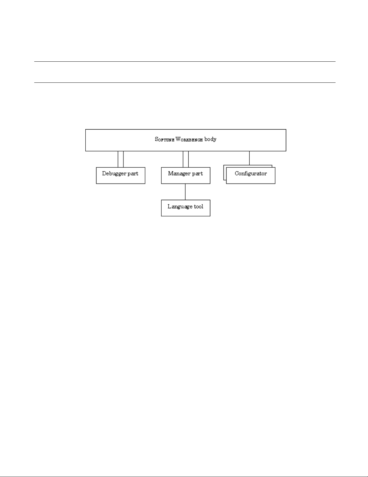
Figure 1.2-1 shows the basic configuration of SOFTUNE WORKBENCH.
Figure 1.2-1 Basic Configuration of SOFTUNE WORKBENCH
As shown in Figure 1.2-1 SOFTUNE WORKBENCH consists of three parts: body, debugger, and
manager.
The debugger part contains the simulator debugger, emulator debugger. These debuggers can be switched
and used as required.
The manager part enables users to code and make programs without full knowledge of language tool (e.g.,
C compiler and assembler) start and option specification.
The configurator is not built into SOFTUNE WORKBENCH because it is an option. Installing this option,
however, enables cooperative operation on SOFTUNE WORKBENCH.
SOFTUNE WORKBENCH manages all processing from programming to debugging in units of projects.
Projects contain all program files, options of tools (e.g., C compiler), and debugger environment setup, etc.
3
Page 16

CHAPTER 1 OUTLINE OF SOFTUNE WORKBENCH
1.3 Procedure for Developing Programs with SOFTUNE WORKBENCH
The procedure for developing programs with SOFTUNE WORKBENCH consists of the
followings:
1. Setting SOFTUNE WORKBENCH operating conditions
2. Designing a project
3. Creating a program source and executing make/build
4. Executing debugging
■ Setting SOFTUNE WORKBENCH operating conditions
When developing a program with SOFTUNE WORKBENCH, first open the development environment
setup dialog box from the [Setup] - [Development] Menu and set environment variables and projects. For
details about how to set environment variables and projects, see Section 4.7.1 Development.
The environment variables set from this dialog box are referenced by language tools such as the C
compiler.
■ Designing a project
Set information for the program to be developed in a project.
When developing a new project, open the new creation dialog box from the [File] - [New] Menu and select
[Workspace/Project File] from the dialog box. The new project creation dialog box opens.
When the project has already existed, the existing project file can be opened from the [File] - [Open
Workspace] Menu. When using the SOFTUNE V01 or V02 project file, see Section 2.13 Reading
SOFTUNE Project Files of Old Versions.
■ Creating a program source and executing make/build
Open the new creation dialog box from the [File] - [New] Menu and select [Text File]. When the editor is
started, write the source program and save it to the file with the [File] - [Save As] Menu.
When a necessary source file is created, register it in the project with the [Project] - [Add Member] Menu.
When registering the source file in the project is completed, execute "make" with the [Project] - [Make]
Menu or execute "build" with the [Project] - [Build] Menu.
If a syntax error occurs during compilation or assembling, double-click the error display location in the
Output Window with the left button of the mouse. The program jumps to the line where the error occurred.
Correct the source file, and then reexecute the [Project] - [Make] Menu.
■ Executing debugging
When a load module file is created, debugging can be executed.
4
Page 17

CHAPTER 2
OPERATION
This chapter explains the basic operation of SOFTUNE
WORKBENCH for each of the following items:
2.1 Parameters to be Entered from Dialog Boxes
2.2 Starting and Terminating SOFTUNE WORKBENCH
2.3 Creating Workspace
2.4 Storing Project
2.5 Creating and Registering Source File in Project
2.6 Definition of Subproject
2.7 Creation of Project Configuration
2.8 Setting Tools
2.9 Setting Linker Options
2.10 Make/Build
2.11 Debugging
2.12 Executing Debugging Only
2.13 Reading SOFTUNE Project Files of Old Versions
2.14 Moving Project File
5
Page 18

CHAPTER 2 OPERATION
2.1 Parameters to be Entered from Dialog Boxes
When key entry is requested from a dialog box, the following four elements can be
written as parameters:
- Data formula
- Address formula
- Identifier
- File name specification
■ Data formula
A data formula consists of a term and an operator. Data formulas comply with C language formulas.
Almost C language formulas are recognized. Some points (e.g, line number and register specification) are
extended. Operations involving floating-point numbers and character strings are not supported. The
overflows that occur during the operation are ignored. Zero division results in an error.
■ Address formula
An address formula is an extension of the data formula; it represents a memory location. Like the data
formula, the address formula consists of a term and an operator. The terms and operators usable in address
formulas are the same as those in data formulas
■ Identifier
Alphabetic characters, numbers, and "_" can be used as identifiers. Each identifier must begin with a
character other than numbers. Uppercase characters are distinguished from lowercase characters or vice
versa.
■ File name specification
File name specification complies with Windows rules.
6
Page 19

CHAPTER 2 OPERATION
2.1.1 Data and Address Formulas (Numerical constant)
The SOFTUNE WORKBENCH provides numeric constants as the terms of data and
address formulas. An integer or floating-point number can be written as a numerical
constant.
■ Integer
When writing an integer, specify a specifier (B', Q', D', H', 0x) representing the base number of the
numerical value. If no specifier is specified, the base number specified by the default is used. The default
base numbers are determined for each of the locations from which values must be entered. For details, see
each dialog box.
The numerical value representation range is from 0 to H'FFFFFFFF.
However, this range is further restricted, depending on the values to be entered.
The minus values are represented such as -D'1.
(Example)
Binary constant B'1010
Octal constant Q'1267
Decimal constant D'1800
Hexadecimal constant H'12AF or 0x12AF
Note:
No blank is allowed between a specifier and a numerical value.
■ Floating-point number
The following two floating-point numbers are supported.
- Single-precision floating-point number (S)....float
- Double-precision floating-point number (D)....double, long double
The internal format and size comply with the floating-point type handled by the C compiler.
"d" specifies an unsigned decimal number.
Nearest value rounding applies to input values. If the represented value is not a normalized number, a
warning message is displayed and the following value is input:
- When an underflow occurs .... The values that can be represented as unnormalized numbers are changed
- When an overflow occurs .... Values are changed to infinity.
[F'][ ]{.d|d[.[d]]}[{S|D}[[+| -]d]]
to unnormalized numbers. The values less than unnormalized numbers are
changed to ± 0.
7
Page 20

CHAPTER 2 OPERATION
A floating-point number can also be specified in a hexadecimal number as follows:
H' hexadecimal - number [.{S|D}]
Note:
If S and D are omitted, D is assumed.
8
Page 21
CHAPTER 2 OPERATION
2.1.2 Data and Address Formulas (Symbols, Line Numbers,
Character Constants)
The SOFTUNE WORKBENCH provides symbols, line numbers, and character constants
as the terms of data and address formulas.
■ Symbol
The symbols used in the source program can be referenced as addresses; they have the type information
generated by the C compiler and other accessory information. The accessory information generated by the
assembler is label information. Each symbol consists of a module name, a function name, and a symbol
name. Specify these names as follows:
[[module-name][\function-name]\] symbol-name
When the source program is written in the assembly language, module-name is the name written in the
operand of the [PROGRAM] statement. When it is written in the C language, module-name is the name of
the source file to be compiled. Function-name is a function name written in the C language; it is valid only
when the source program is written in the C language.
To distinguish a global symbol from others, write it as \symbol-name.
Table 2.1-1 shows symbol description.
No Japanese character strings can not be used for symbols.
Table 2.1-1 Symbol Cannot Description
Symbol Local symbol in function → static symbol in module → global symbol
\Symbol Local symbol in the specified function in the current module
\function\symbol Static symbol in the specified module or global symbol defined in the
Module\symbol Local symbol in the specified function in the specified module
Module\function\symbol Symbol in class (Valid for static)
■ Line number
The line numbers to be generated by the C compiler or assembler can be used to reference addresses. For
the C language, a line number indicates the starting address when one line is compiled.
Description Contents
Global symbol
specified module
Symbol in class function
[source file-name]$line-number
When referencing an address with a line number, prefix $ to the line number. A line number can be
specified only in a decimal number. Specify the line number in the following format. If the extension of the
9
Page 22

CHAPTER 2 OPERATION
source file name is .c, line number specification can be omitted. If the source file name is not alphanumeric
characters, enclose the line number in double quotes.
■ Character constant
A character constant is the character value enclosed in a single quote; it cannot include a single quote and \.
Instead of these characters (single quote and back slash), escape characters can be used as character
constants. Characters that can constitute character strings can be used as escape characters.
10
Page 23

CHAPTER 2 OPERATION
2.1.3 Data and Address Formulas (Register name, Flag name)
The SOFTUNE WORKBENCH provides register and flag names as the terms of data and
address formulas.
■ Register name, flag name
Register and flag names can be specified in data formulas; they represent the register values at that point of
time.
Specify the register name and flag name, following %.
Usable register names differ for each MCU; see Appendix A Register Names.
11
Page 24

CHAPTER 2 OPERATION
2.1.4 Operators Usable in Data and Address Formulas
Table 2.1-2 lists the operators that can be used in data and address formulas and their
priorities.
■ Operators Usable in Data and Address Formulas
Table 2.1-2 List of Operators Usable in Data and Address Formulas
Priority Symbol Explanation Type of operator
1 ( )
[ ]
.
- >
2 -
&
!
~
*
sizeof
(type)
3 *
/
%
4 +
-
5 <<
>>
6 <
<=
>
>=
Priority change
Subscript representation
Structure
Structure pointer
Minus sign
Address
Logical NOT
Bit NOT
Memory indirect reference
Size (byte)
Type cast
Multiplication
Division
Remainder
Addition
Subtraction
Left shift
Right shift
Less than
Less than or equal to
Greater than
Greater than or equal to
Linear expression
Binary operator
Binary operator
Binary operator (Relational operator)
12
7 ==
!=
8 & Bit AND Binary operator
9 ^ Bit EOR
10 | Bit OR
11 && Logical AND
12 || Logical OR
Equal to
Not equal to
Page 25

Remarks:
CHAPTER 2 OPERATION
When the comparison result is true, the relational operator becomes H'1. When false, it becomes
H'0. The SOFTUNE WORKBENCH does not support the conditional operator (?:), comma operator
(,), increment operator (++) and decrement operator (--) of C language.
13
Page 26

CHAPTER 2 OPERATION
2.1.5 Address Formula Specification
Address formula specification is divided into the addressing and Address range
specification.
■ Addressing
The addressing format is as follows:
16-bit-addressing
16-bit-addressing: ....Expression for addressing
■ Address range specification
Address range specification, representing a memory range, consists of two addressings; it has any of the
following two formats:
Addressing..addressing (from starting address to ending address)
Addressing..+ offset (from starting address to starting address + offset)
offset: Value relative to addressing (starting address)
■ Bit addressing
The notation below is used to represent a bit address. Symbols for bit address attributes can be also used.
Bit addressing is valid when /BIT is specified in the command qualifier.
bit-offset: ....Value used to specify a bit position
When addressing is omitted, address 0 is assumed.
[addressing] : bit-offset
14
Page 27

CHAPTER 2 OPERATION
2.1.6 File Name Specification
File name specification complies with Windows for host environment.
■ File name specification
[drive-name:] [directory-path-name] file-name [.extension]
When drive-name is omitted, the current drive is selected.
15
Page 28

CHAPTER 2 OPERATION
2.2 Starting and Terminating SOFTUNE WORKBENCH
This section explains how to start and terminate SOFTUNE WORKBENCH.
■ Starting and terminating SOFTUNE WORKBENCH
With SOFTUNE V3, to start SOFTUNE WORKBENCH, double-click the [F2MC-8L Family Softune
Workbench] icon in the [Softune V3] group.
When this program is started for the first time with SOFTUNE Manager V01 or V02 installed, the dialog
box is displayed which asks whether or not to take over information for [Setting editor], [Setting tools], and
[Setting error jump] set in the previous version. To take over the information, click the [Yes] button. Not to
take over it, click the [No] button.
■ Terminating SOFTUNE WORKBENCH
To terminate SOFTUNE WORKBENCH, select [Exit] from the [File] Menu or click the x button above
and on the right of the window.
SOFTUNE WORKBENCH cannot be terminated when compile/assemble, make, build, or tool is being
executed. Be sure to terminate SOFTUNE WORKBENCH after compile/assemble, make, build, or tool has
been terminated or suspended.
16
Page 29

CHAPTER 2 OPERATION
2.3 Creating Workspace
Workspace is necessary to store projects in SOFTUNE WORKBENCH to register project,
follow the steps below.
■ Creation of Workspace
SOFTUNE WORKBENCH uses the following methods to create workspace.
- Creating workspace in creating new project
When a new project is created, workspace to store the project is also created.
In this case, the name and position of workspace are the same as those of the project.
- Creating workspace in opening project
When [File]-[Open Workspace] is selected to open a project, workspace to store the project is also
created.
In this case, the name and position of workspace are the same as those of the project.
If any workspace file already exists, however, it is opened instead of the project file.
- Creating blank workspace
Blank space that has no project is created. Projects must be stored separately.
In this case, projects can be stored different in name and position from workspace.
■ Creating Workspace in Creating New Project
1. Select [File]-[New].
When the [New] dialog is opened, select "Workspace/Project File" in [Type of File] and click the [OK]
button.
2. Select the [Project] tab.
When the [New] dialog is opened, select the [Project] tab.
3. Select [Create New Workspace].
Click the [Create New Workspace] check button to create workspace. Create workspace in the same
way that a new project is created.
■ Creating Workspace in Opening Project
1. Select [File]-[Open Workspace].
2. Select "Project File" in [Type of File].
When the [Open Workspace] dialog is opened, select "Project File" in [Type of File].
3. Select the project file to be opened.
Select the project file to be opened.
4. Click the [Open] button.
■ Creating Blank Workspace
1. Select [File]-[New].
When the [New] dialog is opened, select "Workspace/Project File" in [Type of File] and click the [OK]
button.
2. Select the [Workspace] tab.
When the [New] dialog is opened, select the [Workspace] tab.
17
Page 30

CHAPTER 2 OPERATION
3. Select the type of workspace.
Select [Blank Workspace] as the type of workspace.
4. Enter the workspace name.
Enter the workspace name. This name is used as a workspace file name. At default it is also used as a
workspace directory (the workspace directory can be changed).
5. Click the [OK] button.
18
Page 31

CHAPTER 2 OPERATION
2.4 Storing of Project
A project is necessary to develop and debug software in SOFTUNE WORKBENCH. To
store a project in workspace, follow the steps below.
■ Storing of Project
SOFTUNE WORKBENCH uses the following methods to store a project in workspace. To store a new
project is as active project in workspace.
- Storing new project in currently opened workspace
A new project is stored in currently opened workspace.
- Storing existing projects in currently opened workspace
Existing projects are stored in currently opened workspace.
■ Storing New Project in Currently Opened Workspace
1. Open workspace to store a project.
Please open workspace to be stored a project.
2. Select [Project]-[Add Project]-[New].
3. Select [Add to Current Workspace].
Click the [Add to Current Workspace] check button.
4. Select [Project Type].
Select the type of file last created in the project [Project Type]. Table 2.4-1 indicates the selectable
project types and their explanation.
5. Select the chip type and target MCU.
Selectable values are indicated in the top-down list. Select the chip and target MCU from the list.
6. Enter the project name.
Enter the project name. This name can be use as a project file name. At default it is also used as a target
file name and project directory (the target file name and project directory can be changed).
7. Set project dependence.
When defining a project as a subproject in another project, place a checkmark in the [Project
Dependence] checkbox and select the project name from the list in the [Project Dependence] checkbox.
8. Click the [OK] button.
"Debug", "Debug\ABS", "Debug\OBJ", "Debug\LST", or "Debug\OPT" directory is created as a
subdirectory in the project directory.
Debug: A directory to store information for each project configuration. The default configuration name as a
new project is created is "Debug".
ABS: Directory in which the target file is stored
OBJ: Directory in which the object file is stored
LST: Directory in which the list file is stored
OPT: Directory in which the option file is stored
When REALOS is selected as the project type, the Setup Wizard of the configurator opens. For details,
19
Page 32

CHAPTER 2 OPERATION
refer to the manual accompanying SOFTUNE REALOS.
Table 2.4-1 List of Project Types
Project type Explanation
Absolute format (ABS) An ordinary program file is created.
Relative format (REL) A relative format file is created.
Library file A library file is created.
REALOS (ABS) A program that uses a real-time operating system is created.
■ Storing Existing Projects in Workspace
1. Open workspace to store a project.
Open workspace to store a project.
2. Select [Project]-[Add Project]-[Project].
3. Select the project to be stored.
Select the project to be stored in the [Add Project] dialog.
4. Set project dependence.
When defining a project as a subproject in another project, place a checkmark in the [Dependence]
checkbox and select the project name from the list in the [Dependence] checkbox.
5. Click the [Open] button.
■ Setting Active Project
The active project is a project that undergoes [Make], [Build], [Compile/Assemble], [Start Debug] and
[Include Dependence] in the menu. [Make], [Build], [Compile/Assemble], and [Include Dependence]
affects the subprojects in the active project.
To set an active project, select [Project]-[Set Active Project]. When the submenu is displayed, select the
name of a project to be made active from the submenu.
■ Deleting Project Stored in Workspace
Select the project to be deleted in the Project window. Select [Delete Project] in the shortcut menu.
The specified project is deleted from workspace, but the project file itself is not deleted.
If the deleted project is used as the subproject in the project within workspace, the project dependence is
also deleted.
Note:
If SOFTUNE REALOS is not installed, REALOS is not displayed as the project type.
20
Page 33

CHAPTER 2 OPERATION
2.5 Creating and Registering Source File in Project
This section explains the procedure for creating a new source file with SOFTUNE
WORKBENCH and registering the file in the project.
■ Creating the new source file
1. Select the [File]-[New] Menu.
When the [New] dialog box opens, select [Text File] from [Types of Files], then click the [OK] button.
2. Select the [File]-[Save As] Menu.
When the [Save As] dialog box opens, select [Text File] from [Types of Files], then click the [OK]
button.
When the file dialog box for specifying the directory to which the created file is to be saved and the file
name opens, select the directory, specify the file name, then click the [Save] button.
■ Registering the created file in the project
Select the [Project]-[Add Member] menu. The File dialog is opened to select the file to be added to the
member. Select the created source file, followed by the folder to be inserted into the Project window, and
click the [Open] button. The file is stored in the project and its name is displayed in the source file category
in the Project window.
■ Storing Created File with Directory in Project
Select the [Project]-[Add Member]-[Directory] menu. The Add Member Directory dialog is opened to
select the folder to be added to the member. Select the directory having the created source file, followed by
the folder to be inserted into the Project window, and click the [OK] button. The file and directory are
stored in the project and the file and directory below the specified directory are displayed in the specified
folder in the Project window.
The type of file to be stored can be restricted by setting [Type of File] in the dialog.
■ To delete files stored in the project
Select a file(s) to be deleted in the Project window. Select "Delete" from the shortcut menu. The selected
file is deleted from the project member, but the file itself is not deleted. Users cannot delete files in the
[Dependencies] category and [Debug] category files.
21
Page 34

CHAPTER 2 OPERATION
2.6 Definition of Subproject
This section explains how to define a subproject.
■ Definition of Subproject
The subproject is a project on which other projects depend.
SOFTUNE WORKBENCH uses the following methods to define a subproject.
- Defining project as subproject in storing it
When created, a new project is defined as a subproject in another project. For the setting method, see
Section 2.4 Storing of Project.
- Defining subproject between existing projects
A subproject is defined between projects in workspace.
Another project is defined as a subproject in the subproject in the parent project. Such a recurrent
definition that the parent project itself serves as a subproject is impossible.
■ Defining Subproject between Existing Projects
1. Select [Project]-[Project Dependence].
2. Select the parent project in which a subproject is defined.
When the [Project Dependence] dialog is opened, select the name of the parent project in which a
subproject is defined from the [Project Name] box.
3. Select the project that is defined as a subproject.
Check the project that is defined as a subproject from those in the [Dependent Project] list.
4. Click the [OK] button.
■ Deleting Subproject from Project
1. Select [Project]-[Project Dependence].
2. Select the parent project from which a subproject is deleted.
When the [Project Dependence] dialog is opened, select the name of the parent project from which a
subproject is deleted form the [Project Name] box.
3. Select the subproject to be deleted.
Deselect the subproject that is deleted from the [Dependent Project] list.
4. Click the [OK] button.
22
Page 35

CHAPTER 2 OPERATION
2.7 Creation of Project Configuration
This section explains how to create a project configuration.
■ Creation of Project Configuration
The project configuration is a series of settings for specifying the characteristics of the target file. By
creating a new project configuration, two or more tool settings can be stored in the project.
When a new project is created, the project configuration is created under a default name of "Debug".
In SOFTUNE WORKBENCH, the project configuration is created as follow.
- Creating project configuration on settings of existing project configuration
A new project configuration is created on the settings of the selected existing project configuration. In the
new project configuration, the same files as those in the original project configuration are always used.
■ Creating Project Configuration on Settings of Existing Project Configuration
1. Select [Project]-[Project Configuration]-[Add and Delete].
2. Select the project to which a project configuration is added.
When the [Add and Delete Project] dialog is opened, select the project to which a project configuration
is added.
3. Click the [Add] button.
Click the [Add] button. The [Add Project Configuration] dialog is opened.
4. Enter the project configuration name.
Enter the unique name of a new project configuration. The characters that can be used to form a name
are "a to z", "A to Z", "0 to 9" and "_".
5. Select the project configuration to which settings are copied.
Select the initial settings of a project configuration to be added. The selected settings of the project
configuration (such as tool options, file configurations, and configurations of subprojects to be build)
are copied as they are.
6. Click the [OK] button.
Click the [OK] button in the [Add Project Configuration] dialog and the [OK] button in the [Add and
Delete Project Configuration] dialog.
■ Setting Active Project Configuration
The active project configuration is at default a project configuration that undergoes [Make], [Build],
[Compile/Assemble], [Start Debug], and [Include Dependence].
1. Select [Project]-[Project Configuration]-[Add and Delete].
2. Select the project configuration that is made active.
When the [Add and Delete Project] dialog is opened, select the name of the project configuration that is
made active.
3. Click the [Active] button.
Click the [Active] button. The specified configuration and its project become active.
4. Click the [OK] button.
23
Page 36

CHAPTER 2 OPERATION
■ Deleting Specific Active Project Configuration from Project
1. Select [Project]-[Project Configuration]-[Add and Delete].
2. Select the project configuration that is deleted from the project.
When the [Add and Delete Project] dialog is opened, select the project configuration name to be deleted.
3. Click the [Delete] button.
Click the [Delete] button. The specified project configuration is deleted. When all project configurations
in a project are deleted, the project itself is also deleted.
4. Click the [OK] button.
24
Page 37

CHAPTER 2 OPERATION
2.8 Setting Tools
When make or build is executed by SOFTUNE WORKBENCH, appropriate options must
be set in such tools as a compiler, assembler and linker. Set these options as follows:
■ Select the [Project]-[Setup Project] Menu
The [Set Project] dialog is opened. The option selected in the [Set Project] dialog box is applicable to two
or more projects. The applicable project configuration can be limited. For example, the settings of project
configurations A and B can be changed. The same setting can be also specified for all project
configurations.
Specify the project configuration in the [Setting Target] box, the project set in tree view, and select the tool
tab.
When the compiler, assembler and linker/librarian are selected, the category can be selected in the top tab
of the setting dialog box for each tool. After the top-down list is opened, select a category. When a category
was selected, the contents in the display are changed and the options included in each category can be set.
In most cases, compiler and assembler options need not be set except when output of list file and make or
build is executed under specific conditions. Set only linker options. For how to set linker options, see
Section 2.9 Setting Linker Options.
■ Click the [OK] button to complete tool setting
When setting all necessary tool options is completed, click the [OK] button. All the set options are
registered in the project; they become valid when make or build is executed.
Clicking the [Cancel] button cancels all the set options.
Note:
When the [Update] button is clicked during tool option setting, the previously set options cannot be
restored.
25
Page 38

CHAPTER 2 OPERATION
2.9 Setting Linker Options
When creating a program with SOFTUNE WORKBENCH, be sure to set a memory map
with a linker option.
■ Automatic Setting of Linker Options
In SOFTUNE WORKBENCH, the following linker options are automatically set on the basis of
information on the MCU selected when a new project is created;
- Specify the internal ROM/RAM address of the MCU in the memory area option.
Internal ROM is output under an area name of "_INROMxx" and internal RAM under an area name of
"_INRAMxx" (where x is numbered consecutively starting with 01).
- Set the automatic disposition mode to mode 2 (optimum automatic disposition by linker).
When creating a program in a mode other than the single-chip mode or when customizing the disposition
of sections, set the [Disposition/Connection] option as the linker option.
■ Setting of Linker Options
In SOFTUNE WORKBENCH, specifying memory mapping is basic to the disposition of each section in
the memory area. Therefore, set a memory area and set each section in the memory area.
■ Set a memory area
Enter a ROM/RAM area name, start address and end address, select an area attribute (ROM or RAM), then
click the [Setup] button. This setting is displayed in the ROM/RAM area list. In the ROM/RAM area,
assign a unique ROM/RAM name so that it does not match other area names.
A easy program consists of a ROM area and a RAM area, but in a complicated program, several area may
be specified.
The number of areas that can be set is not limited; set all the areas necessary to configure the memory map
of the program to be developed.
■ Set the sections to be allocated to each of the set areas
Selecting the area from the ROM/RAM area list and clicking the [Setup Section] button opens the [Setup
Section] dialog box, enabling the sections to be allocated to the selected area. When selecting an area, click
the start address of the area.
When the [Setup Section] dialog box opens, specify section names in the order the sections are allocated to
the area. Specify section names one by one. When section name specification is completed, click the
[Setup] button to register the section names in the section name list.
When execute make/built the sections are allocated to the area in the order the section names were
registered in the section name list.
When setting the sections to be allocated to one area is completed, click the [OK] button to return the linker
option setting dialog box. Also set other areas in the same way.
26
Page 39

Reference:
CHAPTER 2 OPERATION
Allocating sections to several areas can be continuously set by changing ROM/RAM area name
display in the uppermost part of the [Setup Section] dialog box. The linker option setting dialog box
need not be returned each time sections are allocated to an area.
27
Page 40

CHAPTER 2 OPERATION
2.10 Make/Build
SOFTUNE WORKBENCH can create a program in two methods: make and build.
■ Make
Compiles or assembles only the modified source file and then links all objects to the library to generate an
object program. SOFTUNE WORKBENCH recognizes the dependency of the include files registered in
the [Dependencies] category of the Project Window to compile or assemble the source file.
Use the [Project]-[Make] Menu to execute make.
■ Build
Not only modified source file, but compiles or assembles all the source files registered in the project and
then links all objects to the library to generate a target file.
Use the [Project]-[Build] Menu to execute build.
■ Stop
Stop is the function that forcibly suspends processing during make, build, compilation, or assembling.
Execute stop with the [Project]-[Stop] Menu during make, build, compilation, or assembling.
28
Page 41

CHAPTER 2 OPERATION
2.10.1 Making or Building of Project
SOFTUNE WORKBENCH enables making or building for each project configuration.
■ Making or Building of Project
[Make] or [Build] in the menu applies to the active configuration of an active project. If a subproject is
defined, priority is given to making or building of the subproject.
For details about how to change the active project and active configuration, see Section 2.4 Storing Project
and Section 2.7 Creation of Project Configuration.
■ Making or Building Specified Project
Select the project to be made or built in the Project window. Select [Make] or [Build] in the shortcut menu.
The active configuration of the specified project is made or built. If a subproject is defined, priority is given
to making or building of the subproject.
■ Changing Subproject Configuration at Making or Building
1. Select [Project]-[Project Configuration]-[Configuration at Build].
2. Select the parent project and configuration.
When the [Set Configuration at Build] dialog is opened, select the project to be set from the [Project]
box. The configuration of a subproject to be made or built is displayed.
3. Select the configuration of a subproject.
Select the configuration to be made or built from [Configuration of Subproject at Make/Build].
4. Click the [OK] button.
29
Page 42

CHAPTER 2 OPERATION
2.11 Debugging
The absolute file created as a result of normal termination of make/build can be
debugged immediately after SOFTUNE WORKBENCH has migrated to the debug
session.
■ Migrating SOFTUNE WORKBENCH to debug session
To enable SOFTUNE WORKBENCH to debug the absolute file, migrate it to the debug session.
To migrate SOFTUNE WORKBENCH to the debug session, select [Start Debug] from the [Debug] Menu
-First debugging after project creation
Setup Wizard for debuggers is started. Set the type of the debugger and others (4.7.2.4 Setup Wizard).
-Second or subsequent debugging after project creation
Start SOFTUNE WORKBENCH in the debugger mode that has been already set. To change the type of the
debugger, select the [Debug]-[End] Menu to terminate debugging once, and then change [Project Setup]
Menu.
■ Loading the target program
When SOFTUNE WORKBENCH enters the debug session, select [Load target program] from the [Debug]
Menu to load the target program. The created program is loaded to the debugger and all debugging
preparations are completed now.
■ Operating the debugger
For how to operate the debugger, see Chapter 3 Windows and Chapter 4 Menus in this manual.
For debugger commands and debugger output error messages, refer to the SOFTUNE WORKBENCH
Command Reference Manual
For the debugger functions (MCU common function, MCU chip dependency function), refer to the
SOFTUNE WORKBENCH Users Manual
30
Page 43

CHAPTER 2 OPERATION
2.12 Executing Debugging Only
SOFTUNE WORKBENCH can be used as the conventional debuggers.
■ Creating a project
In SOFTUNE WORKBENCH, projects are a basis of all work. This is not an exception also at debugging.
For this reason, executing debugging only requires the creation of a project for debugging.
First, create the project for debugging and the workspace which stores the project in the following procedure:
1. Select [New] from the [File] Menu.
2. Select [Project/Workspace File] from the file open dialog box.
-Select the absolute format (ABS) from the new creation dialog box for the project.
-Specify a project name.
-Specify a project directory.
-Select a target MCU name and chip type.
■ Setting of Workspace
Perform setting common to projects to be stored in workspace.
1. Select [Set Workspace] from the [Project] menu.
2. When the [Set Workspace] dialog is opened, perform the following setting:
• Debug when workspace opened: Start debugging.
• Save setup information: Save.
■ Settings related to the debugger
1. Select [Project Setup] from the [Project] Menu.
2. When the setup dialog box opens, open the [Debug] tag and select [Setup] category:
3. Set a setup name.
A project name is set both in [Setup Name List] and [Valid Setup Name] as the default setup name.
Usually, setup names are identified by the type of the debugger to be used. However, if only one
debugger is used, the default name may be set as it is.
When the default name is used as is, select the default name already set in [Setup Name List], then click
the [Change Setup] button. When another name is used, specify [Setup Name], then click the [Add
Setup] button.
■ Setup Wizard
Clicking the [Add Setup] or [Change Setup] button starts the Setup Wizard for debuggers. Once Setup
Wizard has been started, set items according to instructions from Setup Wizard. For how to set items with
Setup Wizard, see Section 4.7.2.4 Setup Wizard.
When all settings with Setup Wizard are completed, click the [Complete] button.
When the [Project Setup] dialog box is redisplayed, click the [OK] button.
When all the above steps are completed, save the project, then close it once.
31
Page 44

CHAPTER 2 OPERATION
■ Starting debugging
When steps from [Creating a project] to [Setup Wizard] are already completed, open the project.
SOFTUNE WORKBENCH automatically migrates to the debug session, enabling the immediate start of
debugging.
Select [Open] from the [File] menu and specify the load module file to load the target program.
32
Page 45

CHAPTER 2 OPERATION
2.13 Reading SOFTUNE Project Files of Old Versions
The SOFTUNE project files of old versions can be read.
■ Procedure
- The project files created in SOFTUNE WORKBENCH V3 version need the following setting.
1. Select [Open Workspace] from the [File] menu.
2. Select 'Project file' from File Type and specify the project file made by the early version of SOFTUNE
WORKBENCH. If the specified file is one made by the early version of SOFTUNE WORKBENCH, a
dialog asking whether to convert the file to a workspace project format is opened.
[Yes] button: The project file is converted and opened in the workspace project format.
[No] button: The project file is not converted and is opened in the old project format. In this case,
some functions cannot be used. For details of functions that can be used in the old
project format, refer to Section 1.2 Management Function for Project of SOFTUNE
WORKBENCH Users Manual.
- The project files created in SOFTUNE Manager V01/V02 version needs the following setting.
1. Select [Open Workspace] from the [File] Menu.
2. Select 'Project file' from File Type and specify the project file made by SOFTUNE Manager. If the
3. Click the [OK] button to start conversion.
4. When the New Project Creation Window opens, set the chip type and target
5. When conversion is completed, the dialog box showing the end of conversion opens. Click the [OK]
■ Backup file
In SOFTUNE WORKBENCH, when a project file is converted to a workspace project format, a backup
file is made automatically. The extension of backup file varies with the type of project file. The method for
opening the backup project file is also different depending on the extension.
SOFTUNE WORKBENCH V3
●
[Cancel] button: Opening of the project file is cancelled.
specified file is one made by SOFTUNE Manager, a dialog asking whether to convert the file to a
workspace project format is opened.
Click the [Cancel] button to cancel opening of the project file.
When you click the [Cancel] button, it cancels the opening of the project file.
MCU, then click the [OK] button.
button to close the dialog box.
Old project file (.prj) → .p03
Old option data file (.dat) → .d03
SOFTUNE MANAGER V01/V02
●
Old project file (.prj) → .V01
33
Page 46

CHAPTER 2 OPERATION
SOFTUNE WORKBENCH V3 (.p03)
●
• Change the extension of the backup project file (.p03) and option data file (.d03) to '.prj' and '.dat,'
respectively.
Softune Manager V01/V02 (.v01)
●
• Change the extension of the backup project file (.v01) to '.prj.'
Note:
- Tool options are not passed to projects. Reset these options after read has terminated.
- Be sure to reset "User Include File Directory" set by "Set Environment Variable" of an old version
as the "Include Path" option of the C compiler or assembler. Also be sure to reset "Library File
Search Path" set by "Environment Variable Setup" of the old version as the "Library Search Path"
option of the linker.
- If the workspace file having the same name as that of the specified project file is in the same
directory, the workspace file is opened instead of the project file, and no project file is converted.
34
Page 47

CHAPTER 2 OPERATION
2.14 Moving Project File
This section explains how to move a project file to another directory or a personal
computer.
■ Procedure
1. Set the path to the member stored in the project file to the relative path from the project file.
In SOFTUNE WORKBENCH, files in the same drive as that of the project file are usually stored in the
relative path. To check whether the files are stored in the relative path, check File Property in the Project
window. For the file property, see Section 4.3.8 Property.
2. Set the path to the target file directory, object file directory and list file directory to the relative path
from the project file.
In SOFTUNE WORKBENCH, when a new project is created, the output directory is set to the relative
path from the project file. To make a change and check, open the [Set Project] dialog. For details, see
Section 4.5.5 Setup Project.
3. Set the directories such as the include path and library path specified in the tool option to the relative
path or macro description.
For the macro description, see Section 1.11 Macro Descriptions Usable in Manager. For the tool option,
see Section 4.5.5 Setup Project of SOFTUNE Workbench Function Manual.
4. After the completion of the setting in steps 1 to 3, save the project.
5. Move the project file without changing the directory structure in steps 1 to 3.
35
Page 48

CHAPTER 2 OPERATION
36
Page 49

CHAPTER 3
Windows
This chapter explains SOFTUNE WORKBENCH
windows.
3.1 Window Configuration
3.2 Tool Bar
3.3 Status Bar
3.4 Project Window
3.5 Output Window
3.6 Edit Window (Standard Editor)
3.7 Source Window
3.8 Symbol Window
3.9 Disassemble Window
3.10 Register Window
3.11 Memory Window
3.12 Local Variable Window
3.13 Watch Window
3.14 Trace Window
3.15 Command Window
3.16 Object Window
3.17 Coverage Window
3.18 Performance Window
3.19 Sequence Window
37
Page 50

CHAPTER 3 Windows
3.1 Window Configuration
Each SOFTUNE WORKBENCH window consists of a menu bar, tool bar, window screen,
and status bar. Menus are explained in Chapter 4.
■ Main Window
Figure 3.1-1 shows the SOFTUNE WORKBENCH Main Window. As shown in this figure, child windows
(e.g., project window and output window) and the tool bar can be shown with the Main Window and
displayed.
Figure 3.1-1 The SOFTUNE WORKBENCH Main Menu
Project
Window
Edit
Window
Output
Window
38
Status Bar
Page 51

CHAPTER 3 Windows
3.2 Tool Bar
Command buttons to be used often are assigned to the tool bar for each group. The
groups that can be selected and the command buttons in the groups are shown below.
■ Common bar
New
Open
Save
Cut
Copy
Paste
Undo
Redo
■ Project bar
The active project and its active configuration name are set and displayed.
■ Build bar
Jump to Next error
Jump to Previous error
Jump to Top error
Jump to Bottom error
Project window Docking
Output window Docking
Open Project window
Open Output window
Compile/Assembly
Make
■ Debug bar
Build
Stop Make/Build
Go
Step In
39
Page 52

CHAPTER 3 Windows
■ Flash (MB2146-09)
Step Over
Step Out
Run Until Cursor
Reset of MCU
Abort
Breakpoint Set/Reset
Register window
Watch window
Memory window
Disassembly
Download Flash Memory
Upload Flash Memory
Erase Flash Memory
■ Flag bar
Display and setting of MCU condition flag status
40
Page 53

CHAPTER 3 Windows
3.3 Status Bar
The current status of SOFTUNE Workbench is displayed. The status bar is displayed in
the last part of the main window.
■ Status bar
The status bar has the areas in which information is displayed. The information and the areas in which it is
displayed are simply shown in Figure 3.3-1 .
Figure 3.3-1 Status Bar
The current status of SOFTUNE WORKBENCH is displayed.
[DEBUG] is displayed when SOFTUNE
WORKBENCH enters the debug session.
An MCU number (e.g., "MB89051") is displayed when
SOFTUNE WORKBENCH is in the debug mode.
The type of the debugger is displayed when SOFTUNE
WORKBENCH is in the debug mode.
The debugger status (e.g., execute, break) is displayed when
SOFTUNE WORKBENCH is in the debug mode.
The current IP (instruction address) when is displayed when
SOFTUNE WORKBENCH is in the debug mode.
41
Page 54

CHAPTER 3 Windows
3.4 Project Window
The name of the current project and the file names registered in the project are
displayed in the tree view format.
■ Project window
Figure 3.4-1 shows an example of the project window.
■ Function
-Display the workspace name
-Display all projects stored in workspace
-Display the subproject
The subproject in the project is displayed below the parent project.
-Display of the project target file name
-Display of all the source file names registered in the project
When a source file name is double-clicked, the editor opens to enable the editing of the source file.
-Display of the include files that are in dependency
When an include file name is double-clicked, the editor opens to enable the editing of the include file.
-Displaying Debugger setup name
When the Debugger setup name is double-clicked, debugging is started based on the setup information.
-Drug and drop
The member can be moved in the Project window and stored from the explorer.
42
Page 55

Figure 3.4-1 Example of Project Window
Workspace name
Target file name of project. It is followed by
the project name and active configuration
name. The active project is given in bold type.
Folder that can be deleted. When opened, the
files and folders stored are displayed. "Source
Files" and "Include Files" are created at
default.
"Dependencies" category, the names of the
files in which dependencies are detected are
displayed. The category cannot be deleted.
"Debug" category. When opened, the setup
name stored is displayed. The category cannot
be deleted.
CHAPTER 3 Windows
■ Project window bitmap image list
Workspace file name
Target file name
Subproject name
Folder
Category
C++ source file
C++ source file (not subject to making or building)
C++ source file in which individual options specified
C++ source file in which individual options specified (not subject to making or building)
C source file
Subproject name
The files stored in project for making or
building are listed.
C source file (not subject to making or building)
C source file in which individual options specified
C source file in which individual options specified (not subject to making or building)
Assembler source file
Assembler source file (not subject to making or building)
43
Page 56

CHAPTER 3 Windows
Assembler source file in which individual options specified
Assembler source file in which individual options specified (not subject to making or
building)
Include file
Include file (with dependence)
Library file
Library file (not subject to making or building)
Object file
Object file (not subject to making or building)
Relative file
Relative file (not subject to making or building)
Simulator Debugger setup name
Valid setup name (for Simulator Debugger)
Emulator Debugger setup name
Valid setup name (for Emulator Debugger)
■ Shortcut menus (Click the right button of the mouse on a workspace name)
There are two menus below:
• Add Project A project is added to workspace.
• Property The property of a workspace file is displayed.
- Add Project
When selected, the following two submenus are displayed.
- New
A new project is added to workspace (See Section 4.5.2 Add Project.).
- Existing Project
An existing project is added to workspace (See Section 4.5.2 Add Project.).
- Property
Information on the workspace file is displayed (See Section 4.3.8 Property.)
■ Shortcut menus (Click the right button of the mouse on a target name)
There are 12 menus below:
• Set Active Project The currently selected project is set in the active project.
• Create New Folder A new folder is created in project.
44
• Add Member to Project A member is added to the project.
• Set Project A project is set.
• Set Linkage Order This checks and changes the Linkage Order of the member files registered in a
project.
• Make Starts make.
• Build Starts build.
• Executing linker or librarian The linker or librarian is started.
Page 57

CHAPTER 3 Windows
• Delete Project The project is deleted from workspace.
• Property Displays output file information.
• Open List File Opens the list file.
• Open HEX File Opens the HEX file. (HEX file information is displayed only when the
project type is "absolute format".)
- Set Active Project
The currently selected project is set in the active project in workspace.
- Create New Folder
When selected, the [Create New Folder] dialog (Figure 3.4-2 ) is opened. Enter the folder name and click
the [OK] button.
- When the folder name is entered, the folder is inserted into the hierarchy immediately below the
project.
- The folders are listed in the order in which they are created.
Figure 3.4-2 Create New Folder Dialog
- Add Member to Project
When selected, the following two submenus are displayed.
•File
A member is added in files to the currently selected project (See Section 4.5.3 Add Member.).
At default, a member is inserted into the hierarchy immediately below the project.
• Directory
A member is added in directories to the currently selected project (See Section 4.5.3 Add Member.).
At default, a member is inserted into the hierarchy immediately below the project.
- Set Project
A project is set (See Section 4.5.5 Setup Project.).
- Set Link Order
When selected, the [Set Linkage Order] dialog (Figure 3.4-3 ) is opened. The files displayed in the
[Linkage Order] box are linked from top to down. To change the link order, select the configuration to be
set from the [Target of Setting] box, followed by the file name, and use the [Up] or [Down] button to
move the file to a desired position.
The [Export] dialog (Figure 3.4-4 ) allows the current order to affect other configurations.
The files not subject to link are displayed in gray.
45
Page 58

CHAPTER 3 Windows
Figure 3.4-3 Set Linkage Order Dialog
Figure 3.4-4 Export Dialog
- Make/Build
Making or building is performed in the active configuration of the currently selected project to create a
target file.
- Start Linker/Librarian
The linker or librarian is started in the active configuration of the currently selected project to create a
target file.
46
Page 59

CHAPTER 3 Windows
- Delete Project
The specified project is deleted from workspace. The project file itself is not deleted.
- Property
Click the right button of the mouse to display the shortcut menu, then select [Property].
- File information is displayed. See Section 4.3.8 Property.
- Open List File
1. Click the right button of the mouse to display the shortcut menu, then select [Open List File].
- The submenu is displayed.
2. Select the list file you want to open.
- If the list file you want to open is not created, no submenu item can be selected.
- Open HEX File
1. Click the right button of the mouse to display the shortcut menu, then select [Open HEX File].
- The submenu is displayed.
2. Select the HEX file you want to open.
- If the HEX file you want to open is not created, no submenu item can be selected.
■ Shortcut menu (Click the right button of the mouse on a subproject name)
There is one menu below:
• Delete Subproject
A subproject is deleted.
- Delete Subproject
The subproject in the specified project is deleted. To define a subproject again, see Section 4.5.7 Project
Dependencies.
■ Shortcut menus (Click the right button of the mouse on a folder)
There are seven menus below:
• Create New Folder
A new folder is created.
• Add Member to Project
A member is added to the project.
•Set
Setting is performed.
•Make
Making is started.
•Build
Building is started.
• Delete
A folder and a member in the folder are deleted.
• Property
Information on folders is displayed.
- Create New Folder
- When selected, the [Create New Folder] dialog (Figure 3.4-2 ) is opened. Enter the folder name and
click the [OK] button.
- When the folder name is entered, a folder is inserted into the selected folder.
47
Page 60

CHAPTER 3 Windows
- The folders are listed in the order in which they are created.
- Add Member to Folder
When selected, the following two submenus are displayed:
- File
A member is added in files to the currently selected project (See Section 4.5.3 Add Member).
At default, a member is inserted into the selected folder.
- Directory
A member is added in directories to the currently selected project (See Section 4.5.3 Add Member).
At default, a member is inserted into the selected folder.
- Set
When selected, the following two submenus are displayed:
- Individual Setting
A project is set (See Section 4.5.5 Setup Project).
- Return to Common Setting
All individual options in the specified folder are returned to common options.
- Make/Build
Making or building is performed in the active configuration of the currently selected project to create a
target file.
- Delete
The selected folder and all files in the folder are deleted from the project. The files themselves are not
deleted.
If the files (RCR files) that cannot be deleted are included, the folder is not deleted.
- Property
Information on folders is displayed (see Section 4.3.8 Property).
■ Shortcut menus (Click the right button of the mouse on a [Dependencies] category)
There are three menus below:
• Make Making is started.
• Build Building is started.
• Property Information on folders is displayed.
- Make/Build
Making or building is performed in the active configuration of the currently selected project to create a
target file.
- Property
Information on folders is displayed (see Section 4.3.8 Property).
■ Shortcut menus (Click the right button of the mouse on a [Debug] category)
There are two menus below:
• Add Setup A debug setup is added.
• Property Information on folders is displayed.
48
Page 61

CHAPTER 3 Windows
- Add Setup
When selected, the following two submenus are displayed:
- New
When selected, the [Create New Setup] dialog (Figure 3.4-5 ) is opened. Enter the setup name and click
the [OK] button.
When the setup name is entered, the setup wizard is started. For details about the setup wizard, See
Section 4.7.2.4 Setup Wizard.
- Reference
When selected, the [Create New Setup] dialog (Figure 3.4-5 ) is opened. Enter the setup name and click
the [OK] button.
When the setup name is entered, the [Select File] dialog is opened. Select the file and click [Open]
button. Information is read from the specified file.
Figure 3.4-5 Create New Setup
- Property
Information on folders is displayed. See Section 4.3.8 Property.
■ Shortcut menu (Click the right button of the mouse on a source file name.)
There are six menus below:
• Open Opens the selected source file.
• Compile (Assemble) Compiles (Assembles) the selected source file.
• Set Setting of project
• Delete Releases the source file from the project.
• Property Displays source file properties.
• Open List File Opens the list file
- Open
Click the right button of the mouse to display the shortcut menu, then select [Open].
- When SOFTUNE WORKBENCH is in the debug session, the specified source file is displayed in the
Source Window.
- When SOFTUNE WORKBENCH is not in the debug session, the specified source file is displayed in
the Edit Window.
- Compile (Assemble)
Click the right button of the mouse to display the shortcut menu, then select [Compile] [Assemble].
- The specified source file is automatically judged whether it is the C or assembler source and then
compiled or assembled.
49
Page 62

CHAPTER 3 Windows
- Set
Click the right button of the mouse to display the shortcut menu, then select [set].
- Individual Setting
A project is set (See Section 4.5.5 Setup Project).
- Return to Common Setting
All individual options in the specified folder are returned to common options.
- Delete
Click the right button of the mouse to display the shortcut menu, then select [Delete].
- The specified file is released from the project member. The file itself is not deleted.
- Property
Click the right button of the mouse to display the shortcut menu, then select [Property].
- File information is displayed. See Section 4.3.8 Property.
- Open List File
Click the right button of the mouse to display the shortcut menu, then select [Open List File].
Select the list file you want to open.
- If the list file you want to open is not created, no submenu item can be selected.
■ Shortcut menu (Click the right button of the mouse on an include file name and other
user's registration file.)
There are three menus below:
• Open Opens the selected include file.
• Delete A file is deleted from the project.
• Property Displays include file information (properties).
- Open
Click the right button of the mouse to display the shortcut menu, then select [Open].
- When SOFTUNE WORKBENCH is in the debug session, the specified include file is displayed in the
Source Window.
- When SOFTUNE WORKBENCH is not in the debug session, the specified include file is displayed in
the Edit Window.
- Delete
Click the right button of the mouse to display the shortcut menu, then select [Delete].
- The specified file is released from the project member. The file itself is not deleted.
- Property
Click the right button of the mouse to display the shortcut menu, then select [Property].
- File information is displayed. See Section 4.3.8 Property.
50
Page 63

CHAPTER 3 Windows
■ Shortcut menus (Click the right button on library file, object file and relative file)
There are three menus below:
• Set Setting is performed.
• Delete A file is deleted from the project.
• Property The property of a file is opened.
- Set
When selected, the following two submenus are displayed:
- Individual Setting
A project is set (See Section 4.5.5 Setup Project).
- Return to Common Setting
All individual options in the specified folder are returned to common options.
- Delete
- The specified file is released from the project member. The file itself is not deleted.
- Property
File information is displayed. See Section 4.3.8 Property.
■ Shortcut menus (Click the right button on [Dependencies] category)
There are two menus below:
• Open the selected file is opened.
• Property The property of a file is opened.
- Open
When selected, the following two submenus are displayed.
When SOFTUNE WORKBENCH is in the debug session, the specified source file is displayed in the
Source Window.
When SOFTUNE WORKBENCH is not in the debug session, the specified source file is displayed in the
Edit Window.
- Property
File information is displayed. See Section 4.3.8 Property.
■ Shortcut menu (Click the right button on setup name.)
There are four menus below:
• Start/End Debug Debugging is started or ended.
• Change Debugger setup information is changed.
• Delete Debugger setup information is deleted.
• Property Debugger setup information is displayed.
- Start /End Debug
- During debugging session, the confirmation dialog "Is the current session ended to start debugging?" is
displayed. Select Yes.
- The current debugging is ended, and then debugging is started based on the specified setup information.
- During non-debugging session, debugging is started without displaying the confirmation dialog.
- Debugging can be started only in the active project.
- In debug session, only the valid setup changes from [Start Debug] to [End Debug]. When [End Debug]
51
Page 64

CHAPTER 3 Windows
is selected, debugging is ended.
- Change
The setup wizard for changing the setup setting is started (see Section 4.7.2.4 Setup Wizard).
- Delete
Debugger setup information is deleted from the project.
Valid setup information cannot be deleted. To delete, change the valid setup temporarily.
- Property
Click the right button of the mouse to display the short cut menu, then select [Property].
Setup information is displayed (see Section 4.3.8 Property).
■ Shortcut menu (Click the right button of the mouse on a place other than project
window characters.)
There are two menus below:
• Docking View Sets or resets the docking view.
• Hide Closes the project window.
- Docking View
Click the right button of the mouse to display the shortcut menu, then select [Docking View].
- The project window is docked with the frame in the check status.
- Hide
Click the right button of the mouse to display the shortcut menu, then select [Hide].
- The project window enters the nondisplay status.
52
Page 65

CHAPTER 3 Windows
3.5 Output Window
The output window displays compiler version information and error messages, etc.,
when make or build is executed.
■ Output window
Figure 3.5-1 is an example of the output window.
As shown in this example, when the left button of the mouse is double-clicked on the line to which an error
message was output, control automatically jumps to the source line where the error occurred.
Figure 3.5-1 Example of Output Window
Tool start message (e.g., version and copyright)
■ Shortcut menu
There are seven menus below:
- Copy Copies the selected character string to the clipboard.
- Clear Clears all the items displayed in the output window.
- Docking View Sets or resets the docking view.
- Nondisplay Places the output window in the nondisplay status.
- Set Font Selects a display font in the output window.
- Keyword Coloring Whether or not to highlight the error number of the error message is set.
- Logging The result of output to the Output window is stored in a file.
■ Operation
- Copy
1. Select the character string you want to copy.
2. Click the right button of the mouse in the output window to display the shortcut menu.
3. Select [Copy] from the shortcut menu.
See Section 4.3.2 Cut, Copy, Paste, Delete.
- Clear
Tool error message (example of C compiler)
1. Click the right button of the mouse in the output window to display the shortcut menu.
53
Page 66

CHAPTER 3 Windows
2. Select [Clear] from the shortcut menu.
- Docking View
1. Click the right button of the mouse in the output window to display the shortcut menu.
2. Select [Docking View] from the shortcut menu.
- The output window is docked with the frame in the check status.
- Display
1. Click the right button of the mouse in the output window to display the shortcut menu.
2. Select [Nondisplay] from the shortcut menu.
- The output window enters the nondisplay status.
- Set Font
1. Click the right button of the mouse in the output window to display the shortcut menu.
2. Select [Set Font] from the shortcut menu.
The font selection dialog box (Figure 3.5-2 ) opens.
3. Select [Font] and [Size], then click the [OK] button.
Figure 3.5-2 Font Setting Dialog Box
54
- Highlight Keyword
1. Display the shortcut menu by clicking the right button on the Output window.
2. Select [Keyword Coloring].
- In the check state, the keyword (error number) of the error message is displayed in red.
- Logging
1. Display the shortcut menu by clicking the right button on the Output window.
2. Select [Logging]-[Start] and then specify the file name of the record target file.
The result of output to the Output window is recorded in the specified file.
3. To suspend logging, select [Logging]-[Record] and uncheck the checkbox. Logging is restarted again
when the checkbox is checked.
4. To stop logging, select [Logging]-[Termination].
Page 67

CHAPTER 3 Windows
3.6 Edit Window (Standard Editor)
The edit window is used to display and edit a source file and document file, etc.
■ Edit window
An example of the edit window docked with the Main Window is given in Figure 3.6-1 .
As shown in this example, the edit window docked with the Main Window can be displayed only when the
standard editor built into SOFTUNE WORKBENCH is in use.
SOFTUNE WORKBENCH can register and use any external editor. In this case, however, the edit
window is not treated as a SOFTUNE WORKBENCH screen.
Figure 3.6-1 Example of Edit Window
Ruler
Line number display
Text editing area
Line selection field
When a read-only file is opened, [Protect] is displayed.
When the Caps key is locked, [CAP] is displayed.
When SOFTUNE WORKBENCH is in the character overwrite editing
mode, [Overwrite] is displayed.
The cursor position is displayed in "line:column".
■ Shortcut menu
- Source Window Opens the Source Window.
- Undo Undoes the last editing.
- Redo Redoes the canceled editing.
- Cut Moves the selected character string to the clipboard.
55
Page 68

CHAPTER 3 Windows
- Copy Copies the selected character string to the clipboard.
- Paste Pastes the character string in the clipboard to the cursor position.
- Delete Deletes the selected character string.
- All select Selects all characters in the buffer.
- Print Prints the file.
- Add to Project Adds the file being edited to the active project.
- Find Opens the character string find dialog box.
- Replace Opens the character string replacement dialog box.
- Find in Files See section 4.3.5 Find in Files.
- Jump Opens the jump line number specification dialog box.
- Tag List See Section 3.6.1 Tag Jump.
- Set Standard Editor See Section 3.6.2 Setting Standard Editor.
- Status Bar Switches status bar display for each window.
- Property Display file information (properties).
- Source Window
1. Click the right button of the mouse to display the shortcut menu, then select [Source Window] from the
menu.
- When SOFTUNE WORKBENCH is in the debug session, the Source Window is displayed. See
Section 3.7 Source Window.
When SOFTUNE WORKBENCH is not in the debug session, this menu cannot be selected
- Undo
1. Click the right button of the mouse to display the shortcut menu, then select [Undo] from the menu.
- SOFTUNE WORKBENCH cancels the last editing and undoes the status before the editing. See
Section 4.3.1 Undo, Redo.
- Redo
1. Click the right button of the mouse to display the shortcut menu, then select [Redo] from the menu.
- SOFTUNE WORKBENCH cancels the last editing.
- Cut
1. Select the character string you want to cut.
2. Click the right button of the mouse to display the shortcut menu, then select [Move] from the menu.
- SOFTUNE WORKBENCH deletes the selected character string from the edit window and moves it to
the clipboard. See Section 4.3.2 Cut, Copy, Paste, Delete.
- Copy
1. Select the character string you want to copy.
2. Click the right button of the mouse to display the shortcut menu, then select [Copy] from the menu.
- SOFTUNE WORKBENCH copies the selected character string to the clipboard. See Section 4.3.2
Cut, Copy, Paste, Delete.
- Paste
1. Move the cursor to the position into which the character string is to be inserted.
2. Click the right button of the mouse to display the shortcut menu, then select [Paste] from the menu.
56
Page 69

CHAPTER 3 Windows
- SOFTUNE WORKBENCH inserts the character string in the clipboard into the cursor position. See
Section 4.3.2 Cut, Copy, Paste, Delete.
- Delete
1. Select the character string you want to delete.
2. Click the right button of the mouse to display the shortcut menu, then select [Delete] from the menu.
- SOFTUNE WORKBENCH deletes the selected character string. See Section 4.3.2 Cut, Copy, Paste,
Delete.
- All select
1. Click the right button of the mouse to display the shortcut menu, then select [All select] from the menu.
- SOFTUNE WORKBENCH selects all the texts in the edit window and displays them in reverse video.
See Section 4.3.3 All Select.
- Print
1. Click the right button of the mouse to display the shortcut menu, then select [Print] from the menu.
- The print dialog box opens. See Section 4.2.9 Print.
- Add to Project
1. Click the right button of the mouse to display the shortcut menu, then select [Add to Project] from the
menu.
- SOFTUNE WORKBENCH adds the file being edited to the project.
- Find/Replace
1. Click the right button of the mouse to display the shortcut menu, then select [Find] or [Replace] from
the menu.
- SOFTUNE WORKBENCH sets the clipboard character string in [Find What] and opens the find or
replace dialog box. See Section 4.3.4 Find/Replace.
- Find in files
1. Click the right button of the mouse to display the shortcut menu, then select [Find in files] from the
menu.
- SOFTUNE WORKBENCH sets the clipboard character string in [Find What] and opens the [Find in
Files] dialog box. See Section 4.3.5 Find in Files.
- Jump
1. Click the right button of the mouse to display the shortcut menu, then select [Jump] from the menu.
-The dialog box for specifying the jump destination line opens. See Section 4.3.6 Jump.
2. Set the jump destination line number.
3. Click the [OK] button.
- Status Bar
Status Bar switches status bar display and non-display for each Edit Window.
1. Click the right button of the mouse to display the shortcut menu, then select [Status Bar] from the menu.
- When the status bar has been already displayed, SOFTUNE WORKBENCH switches status bar
display to nondisplay and deletes the check mark from the menu.
- When the status bar is not displayed, SOFTUNE WORKBENCH displays the status bar and adds a
check mark to the left end of the menu.
- Property
1. Click the right button of the mouse to display the shortcut menu, then select [Property] from the list.
- SOFTUNE WORKBENCH displays file information. See Section 4.3.8 Property.
57
Page 70

CHAPTER 3 Windows
3.6.1 Tag Jump
This section explains the tag jump function of the standard editor.
■ Tag jump
The standard editor has a function to immediately return control from one place to the tag assigned to the
line where the current cursor exists in the edit window. This function is called tag jump.
Several tags can be set.
■ Tag setting procedure
1. Click the right button of the mouse in the edit window to display the shortcut menu.
2. Select [Tag List] from the shortcut menu.
The tag list dialog box shown in Figure 3.6-2 opens. SOFTUNE WORKBENCH operation (e.g., source
file editing) can be continued with the tag list dialog box being open. This is because the tag list dialog
box is a modeless dialog box.
3. Move the cursor to the line to which a tag in the Main window is to be assigned.
4. Click the [Add] button from the tag list dialog box.
■ Tag deletion procedure
1. Click the right button of the mouse in the edit window to display the shortcut menu.
2. Select [Tag List] from the shortcut menu.
The tag list dialog box shown in Figure 3.6-2 opens.
3. Select the tag you want to delete.
4. Click the [Delete] button.
Figure 3.6-2 Tag List Dialog Box
■ Tag jump procedure
1. Click the right button of the mouse in the edit window to display the shortcut menu.
2. Select [Tag List] from the shortcut menu.
The tag list dialog box shown in Figure 3.6-2 opens.
3. Select the tag to which the cursor is to jump.
4. Click the [Jump] button.
58
Page 71

3.6.2 Setting Standard Editor
This section explains how to customize the standard editor.
■ Setting the standard editor
Some standard editor functions can be customized.
- Items that can be customized
-Display fnction
- Line feed mark display
- Tag code mark display
- EOF code mark display
- Line number display
- Ruler display
- Automatic indent function
- Colored display of C keyword
CHAPTER 3 Windows
- Colored display of ASM keyword
- Colored display of user keyword
- Colored display of comment statement
- Font
- Tab count
- Display color
-Tag
- Error line
- C keyword
- Assembly keyword
- User keyword
- Comment statement
- Line Feed
-Tab
- Keyword to be highlighted
■ Customization procedure (display function selection)
1. Click the right button of the mouse in the edit window to display the shortcut menu, then select
[Customize...] from the menu.
The standard editor dialog box shown in Figure 3.6-3 opens.
2. Select the function item you want to set or reset, then click to the left of the item.
3. When not setting other items, click the [OK] button.
When selecting a color, set all the related items, then click the [OK] button.
■ Customization procedure (display color selection)
1. Click the right button of the mouse in the edit window to display the shortcut menu, then select
59
Page 72

CHAPTER 3 Windows
[Customize...] from the menu.
The standard editor dialog box shown in Figure 3.6-3 opens.
2. Click the color button of [Tag], [Error], [C], or [Assembly]. From [View2] tab, you can set a
[Comment], [Ret], [Tab], and [User Keyword].
The color dialog box opens.
3. Select a color from the dialog box, then click the [OK] button.
The color of the button changes to the selected color.
4. When not setting other items, click the [OK] button.
When selecting a font, set all the related items, then click the [OK] button.
■ Customization procedure (font selection)
1. Click the right button of the mouse in the edit window to display the shortcut menu, then select
[Customize...] from the menu.
The standard editor dialog box shown in Figure 3.6-3 opens.
2. Click the [Font] button.
The font selection dialog box opens.
3. Select a font and size, then click the [OK] button.
4. When not setting other items, click the [OK] button.
When specifying a tab count, set all the related items, then click the [OK] button.
■ Customization procedure (tab count)
1. Click the right button of the mouse in the edit window to display the shortcut menu, then select
[Customize...] from the menu.
The standard editor dialog box shown in Figure 3.6-3 opens.
2. Modify the value displayed in the [Tab Count] field.
3. When not setting other items, click the [OK] button.
When selecting a display function, set all the related items, then click the [OK] button.
■ Customization procedure (keyword addition)
1. Click the right button of the mouse in the edit window to display the shortcut menu, then select
[Customize...] from the menu.
The standard editor dialog box shown in Figure 3.6-3 opens.
2. Click [View2] tab to choose the keyword type to be changed from the combo box.
Click [Datail...] button.
The keyword dialog box shown in Figure 3.6-5 opens.
3. Enter the keyword to be highlighted in [New Item] field. Click [Add] button.
4. Click the [OK] button.
The keyword files is changed.
5. When not setting other items, click the [OK] button.
When selecting a display function, set all the related items, then click the [OK] button.
60
Page 73

■ Customization procedure (deletion of keyword)
1. Click the right button of the mouse in the edit window to display the shortcut menu, then select
[Customize...] from the menu.
The standard editor dialog box shown in Figure 3.6-3 opens.
2. Click [View2] tab to choose the keyword type to be changed from the combo box.
Click [Datail...] button.
The keyword dialog box shown in Figure 3.6-5 opens.
3. Choose the keyword to be deleted from the [Keyword List]. Click [Delete] button.
4. Click the [OK] button.
The keyword files is changed.
5. When not setting other items, click the [OK] button.
When selecting a display function, set all the related items, then click the [OK] button.
■ Customization procedure (initialization of keyword)
1. Click the right button of the mouse in the edit window to display the shortcut menu, then select
[Customize...] from the menu.
The standard editor dialog box shown in Figure 3.6-3 opens.
2. Click [View2] tab to choose the keyword type to be changed from the combo box.
Click [Datail...] button.
The keyword dialog box shown in Figure 3.6-5 opens.
CHAPTER 3 Windows
3. Click [Reset] button.
4. Click the [OK] button.
The keyword files is changed.
5. When not setting other items, clock the [OK] button.
When selecting a display function, set all the related items, then click the [OK] button.
Figure 3.6-3 Standard Editor Dialog Box
61
Page 74

CHAPTER 3 Windows
Figure 3.6-4 Standard Editor Dialog Box (View2)
Figure 3.6-5 Keyword Dialog Box
62
Page 75

3.7 Source Window
The Source Window displays the source program at debugging.
■ Source Window
Figure 3.7-1 is an example of the Source Window.
■ Function
- Breakpoint setting/releasing
A breakpoint can be set or released by left-clicking '=>❍' of '❍' at the left edge of the Source Window.
- Instruction execution to specified line (address)
An instruction can be executed at the specified line (address) by left-clicking of '=>❍' of '❍' at the left
edge of the Source Window. Step execution (step/into) is also enabled by clicking the left mouse button
at the PC location.
Figure 3.7-1 Example of Source Window
CHAPTER 3 Windows
Line number
The position of the
current instruction
pointer is displayed.
The breakpoint position
is displayed.
■ Shortcut Menu
- Edit Opens the edit window.
- Inline Assembly Opens the Inline Assemble dialog box.
- Find Opens the Find dialog box Figure 3.7-2 .
- Jump Displays Jump Dialog Box.
- Go to Current Displays current PC location.
- Break See Section 4.6.4 Break Point.
- Watch Additionally sets watch point
- Stack See Section 4.6.7 Stack.
- Property Displays Window properties.
- Mixed Display Switches whether to display or not disassemble list.
- Close Closes Source Window.
63
Page 76

CHAPTER 3 Windows
- Edit
Opens the edit window to modify the current source file.
See Section 3.6 Edit Window (Standard Editor).
- Find
Find the current source file for a character string. Perform this operation in the following procedure:
1. Click the right button of the mouse in the Source Window to display the shortcut menu, then select
[Find] from the menu.
The search dialog box shown in Figure 3.7-2 opens.
2. Set the character string you want to find.
3. Set a find direction.
4. If necessary, display a check mark to the left of [Distinguish Uppercase from Lowercase].
5. Click the [Find Next] button.
The fond character string is displayed in reverse video.
6. To terminate search, click the [Cancel] button.
Figure 3.7-2 Find Dialog Box in Source Window
64
- Jump
Specifies where in the source window the source program is to be displayed. Perform this operation in
the following procedure:
1. Click the right button of the mouse in the Source Window to display the shortcut menu, then select
[Jump] from the menu. See Section 4.3.6 Jump.
2. Select a specification format.
3. Specify a cursor display position.
4. Click the [OK] button.
- Watch
Specifies the variable to watch and opens the watch window. Perform this operation in the following
procedure:
1. Click the right button of the mouse in the Source Window to display the shortcut menu, then select
[Watch] from the menu. See Section 4.4.7 Watch.
2. Specify a variable name.
3. Select a [mode] as required.
4. Click the [OK] button.
Page 77

CHAPTER 3 Windows
- Property
1. Click the right button of the mouse to display the shortcut menu, then select [Property] from the menu.
- File information is displayed see Section 4.3.8 Property.
- Mixed Display
1. Click the right button of the mouse to display the shortcut menu.
2. Check [Mixed Display].
When a check mark is displayed to the left of [Mixed Display], mixed display has been already set.
When a check mark is not displayed to the left of [Mixed Display], mixed display has not been set yet.
3. Select [Mixed Display].
- When it has been already set, mixed display is reset and the check mark is deleted.
- When it has not been set, mixed display is set and a check mark is displayed.
65
Page 78

CHAPTER 3 Windows
3.8 Symbol Window
The Symbol Window displays the target file name of the current project and the symbol
names (e.g., variable name and function name) being used by the file in the tree view
format.
■ Symbol Window
Figure 3.8-1 is an example of the Symbol Window.
Figure 3.8-1 Example of Symbol Window
The load module name is displayed.
The global symbol and the function name is
displayed.
■ Shortcut Menu
Jump Opens the Source Window of the specified function.
Watch Sets specified symbol as watch point.
Break See Section 4.6.4 Break Point.
Property Displays symbol properties.
The local symbol name defined in the function
is displayed.
Module name is displayed.
The local symbol and function name (static) in
the module is displayed.
66
Mangle name Specify whether to display a symbol name as a mangled name.
Refresh The latest symbol information is displayed.
Close Closes Symbol Window.
- Jump
1. Click the right button of the mouse on the function name to display the shortcut menu, then select
[Jump] from the menu.
The source window in which the function is defined opens.
Page 79

CHAPTER 3 Windows
- Watch
1. Click the right button of the mouse on the variable or function name to display the shortcut menu, then
select [Watch] from the menu. The variable or function is added to the watch and the Watch Window is
displayed.
- Property
1. Click the right button of the mouse to display the shortcut menu, then select [Property] from the menu.
File information is displayed see Section 4.3.8 Property.
- Mangle name
1. Click the mouse right button to open the shortcut menu and select [Mangled name]. Switch between
display and non-display of a symbol name as a mangled name.
- Refresh window
1. Click the mouse right button to open the shortcut menu and select [Refresh window]. The latest symbol
information is displayed.
67
Page 80

CHAPTER 3 Windows
3.9 Disassemble Window
The Disassemble window displays the result obtained by executing disassembling at
the specified address. This window is displayed only when SOFTUNE WORKBENCH is
in the debug session.
■ Disassemble Window
Example the Disassemble Window displays at Figure 3.9-1 .
■ Function
- Breakpoint setting/releasing
A breakpoint can be set or released by left-clicking '=>❍' of '❍' of at the left edge of the Disassemble
Window.
- Instruction execution at specified line (address)
An instruction can be executed at the specified line (address) by left-clicking of '=>❍' of '❍' at the left edge
of the Disassemble Window. Step execution (step/into) is also enabled by clicking the left mouse button at
the PC location.
The position of the
current instruction
pointer is displayed.
The position at which
the breakpoint is set is
displayed.
An address is displayed.
Figure 3.9-1 Disassemble Window
A machine code is
displayed.
A mnemonic is
displayed.
An operand is
displayed.
68
Page 81

■ Shortcut Menu
Inline Assemble See Section 4.4.3 Assembly.
Jump Displays Jump Dialog Box.
Go to Current Displays current PC location.
Break See Section 4.6.4 Break Point.
Watch See Section 4.4.7 Watch.
Stack See Section 4.6.7 Stack.
Close Closes Disassemble Window.
- Jump
Specifies where in the Disassemble Window the cursor is to be displayed. Perform this operation in the
following procedure:
1. Click the right button of the mouse in the Disassemble Window to display the shortcut menu, then select
[Jump] from the menu. See Section 4.3.6 Jump.
2. Select a specification format.
3. Specify a cursor display position.
4. Click the [OK] button.
CHAPTER 3 Windows
69
Page 82

CHAPTER 3 Windows
3.10 Register Window
The Register Window is used to display and modify MCU register values during
debugging. This window is displayed only when SOFTUNE WORKBENCH is in the
debug session.
■ Register Window
Figure 3.10-1 is an example of the Register Window. When debugging, the Register Window displayed the
register values. Register values can be rewritten directly. To rewrite values using expressions and symbols,
etc., select [Edit] from the shortcut menu for the Register Window.
Arrange registers according to the size of the Register Window.
To select the registers to be displayed, select [Display Setup] from the shortcut menu for the Register
Window.
Figure 3.10-1 Example of Resister Window
■ Shortcut Menu
- Setup Setup See Section 3.10.1 Setting Register Display.
- Edit Displays Register Edit Dialog Box.
- Close Closes Register Window.
- Edit
Edits register values. Beside this operation, the numerical values displayed in the Register Window can
be directly edited. See Section 4.4.4 Register.
1. Click the right button of the mouse in the Register Window to display the shortcut menu, then select
[Edit] from the menu.
The register edit dialog box opens.
Each condition flag status is
displayed; it can be also changed.
Register names and values are
displayed. A displayed register
value can be rewritten by entering
a new value.
70
2. Select a register name.
3. Enter the value you want to set.
4. Click the [OK] button.
Page 83
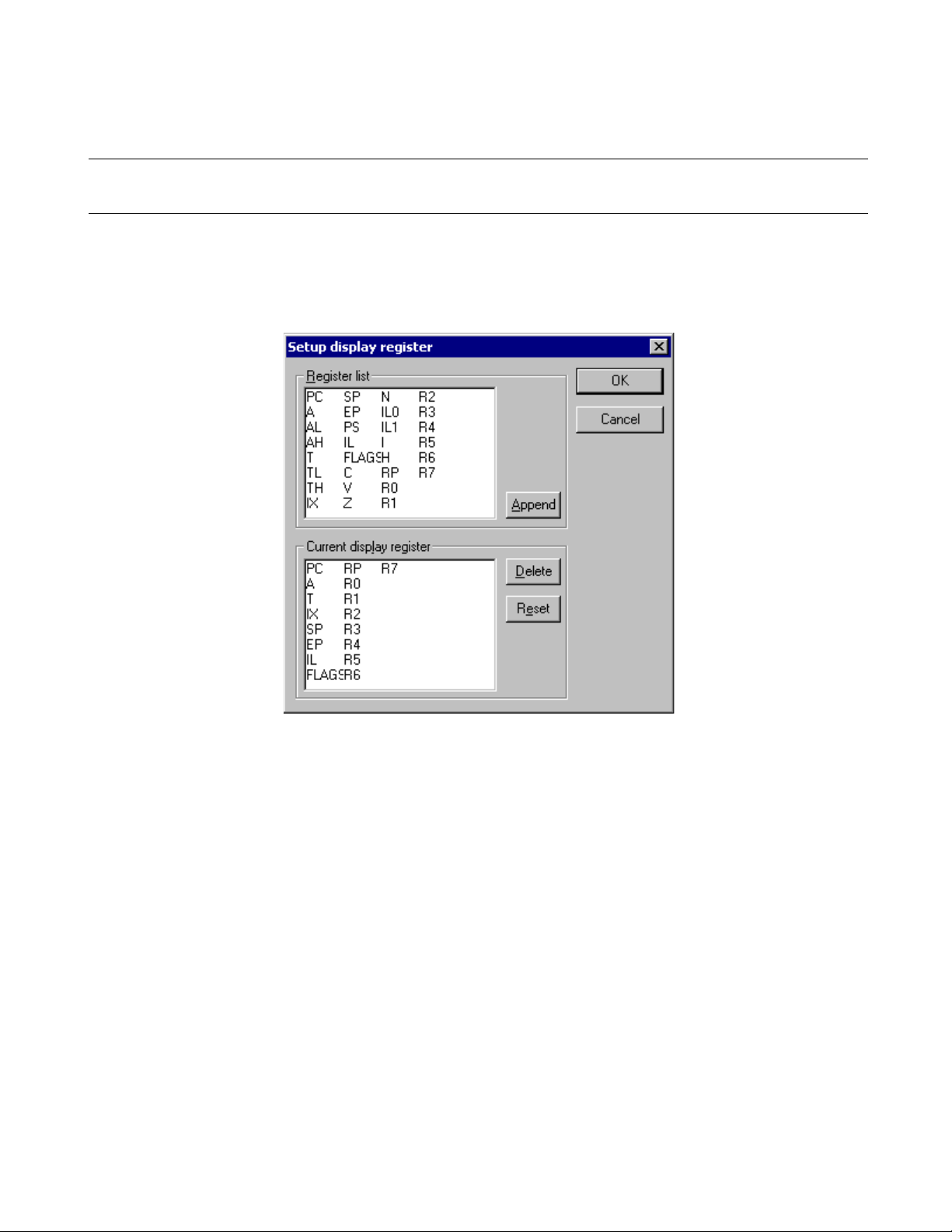
3.10.1 Setting Register Display
This section explains how to set register display.
■ Setting register display
Set the registers to be displayed in the Register Window in the following procedure:
Figure 3.10-2 Display Register Setting Dialog Box
CHAPTER 3 Windows
■ Adding registers
Add the register you want to display in the following procedure:
1. Click the right button of the mouse in the Register Window to display the shortcut menu, then select
[Display Setup] from the menu.
The display setting dialog box shown in Figure 3.10-2 opens.
2. Select the register you want to display from [Register List] (upper part of display register setting dialog
box), then click the [Add] button.
The selected register is set in [Current Display Register] (lower part).
3. Set all the registers you want to display by repeating the above operation.
4. Click the [OK] button.
■ Deleting registers
Select the register you want to delete in the following procedure:
1. Click the right button of the mouse in the Register Window to display the shortcut menu, then select
[Display Setup] from the menu.
The display setting dialog box shown in Figure 3.10-2 opens.
2. Select the register you want to delete from [Register List] (lower part of display register setting dialog
box), then click the [Delete] button.
71
Page 84

CHAPTER 3 Windows
The selected register is deleted from [Current Display Register] (lower part).
3. Set all the registers you want to delete by repeating the above operation.
4. Click the [OK] button.
■ Restoring registers to the initial status
Restore the registers in [Current Display Registers] to the initial status (status when SOFTUNE
WORKBENCH was installed) in the following procedure:
1. Click the right button of the mouse in the Register Window to display the shortcut menu, then select
[Display Setup] from the menu.
The display setting dialog box shown in Figure 3.10-2 opens.
2. Click the [Reset] button.
The registers in [Current Display Registers] (lower part of display register setting dialog box) are
restored to the initial status.
3. Click the [OK] button.
72
Page 85

CHAPTER 3 Windows
3.11 Memory Window
The Memory Window is used to display and modify memory data at the specified
address. This window opens only when SOFTUNE WORKBNCH is in the debug
session.
■ Memory Window
Figure 3.11-1 is an example of the Memory Window. When debugging, the Memory Window is displayed
the memory values. Memory values can be directly rewritten.
To modify by specifying the expression and symbol in the memory values, select [Display Setup] from the
shortcut menu for the Memory Window.
Figure 3.11-1 Example of Memory Window
Data display section.
Displayed data can be
directly modified.
■ Shortcut Menu
- Compare See Section 4.4.5 Memory.
- Find See Section 4.4.5 Memory.
- Special See Section 4.4.5 Memory.
- Inline Assemble See Section 4.4.3 Assembly.
- Jump See Section 4.3.6 Jump.
- Edit See Section 4.4.5 Memory.
- Setup See Section 4.4.5 Memory.
- Break See Section 4.6.4 Break Point.
- Event See Section 4.6.5 Event.
- Watch See Section 4.4.7 Watch.
- Monitoring Switches whether to enable or disable monitoring.
- Close Closes the Memory Window.
Characters (e.g., control codes)
other than ASCII characters are
all represented in ’.’.
Column title. This
line is not scrolled.
73
Page 86

CHAPTER 3 Windows
3.12 Local Variable Window
The Local Variable Window is used to display and modify local variable values. This
window is displayed only when SOFTUNE WORKBENCH is in the debug session. Local
variables are displayed in the tree format (function name root).
■ Local Variable Window
Figure 3.12-1 is an example of the Local Variable Window.
Figure 3.12-1 Example of Local Variable Window
A function name is displayed.
The local symbol names defined in
the function and the current values
are displayed.
■ Shortcut Menu
- Radix See Section 4.4.6 Local.
- Element See Section 4.4.6 Local.
- Edit See Section 4.4.6 Local.
- Memory Window Display the Memory Window based on a selected variable as a start address.
- Property Displays symbol properties.
- Close Closes Local Window.
- Property
1. Click the right button of the mouse on a displayed variable name to display the shortcut menu, then
select [Property] from the menu.
Information for the variable is displayed. For details, see Section 4.3.8 Property.
An array variable name is displayed.
Array data is displayed.
Variables of floating point type are
displayed.
74
2. Click the [Close] button.
Page 87

CHAPTER 3 Windows
3.13 Watch Window
The Watch Window is used to display and modify the values of the specified variables.
This window is displayed only when SOFTUNE WORKBENCH is in the debug session.
Variables are displayed in the tree format.
■ Watch Window
The Watch Window can be opened independent 4-windows. When being registered a variable for each
window, user select watch window number (1,2,3 or 4).
Figure 3.13-1 is an example of the Watch Window.
Figure 3.13-1 Example of Watch Window
A normal variable is displayed.
A structure variable is displayed.
■ Shortcut Menu
- Radix See Section 4.4.7 Watch.
- Setup See Section 4.4.7 Watch.
- Element See Section 4.4.7 Watch.
- Edit See Section 4.4.7 Watch.
- Delete See Section 4.4.7 Watch.
- All Delete See Section 4.4.7 Watch.
Structure members are displayed.
The value of a pointer variable is
displayed.
An array variable is displayed.
Each element of the array variable
is displayed.
State of monitoring is displayed.
(blue:on, red:off)
- Memory window Display the Memory Window based on a selected variable as a start address.
- Monitoring Switches whether to enable or disable monitoring.
- Individual setting The each variable which is registered, user sets "ON" or "OFF" of monitoring.
User distinguishes between "ON" and "OFF" by a color of square ICON. A
blue means on, and a red means off.
- Property Displays watch properties.
75
Page 88

CHAPTER 3 Windows
- Close Closes Watch Window.
- Property
1. Click the right button of the mouse on a displayed variable name to display the shortcut menu, then
select [Property] from the menu.
Information for the variable is displayed. For details. See Section 4.3.8 Property.
2. Click the [Close] button
76
Page 89

CHAPTER 3 Windows
3.14 Trace Window
This section explains the Trace Window. This window is displayed only when
SOFTUNE WORKBENCH is in the debug session.
■ Trace Window
The Trace Window displays the trace result. For the trace function, see Section 4.4.8 Trace. Figure 3.14-1
is an example of the Trace Window
Figure 3.14-1 Example of Trace Window
Column title. This line
is not scrolled.
■ Shortcut Menu
- Refresh Refresh Trace Window.
- Jump See Section 4.3.6 Jump.
- Back Trace See Section 4.4.8 Trace.
- Instruction Displays trace result in instruction mode (Valid when the emulator debugger is
- Cycle Displays trace result in cycle mode (Valid when the emulator or simulator
- Source Displays trace result in source mode (Valid when the emulator or simulator
- Setup See Section 4.4.8 Trace.
- Find See Section 4.4.8 Trace.
- Save Saves Trace data.
- Clear Clears trace buffer.
- Close Closes Trace Window.
- Instruction/cycle/source
1. Click the right button of the mouse to display the shortcut menu.
used).
debugger is used).
debugger is used).
77
Page 90

CHAPTER 3 Windows
2. Select [Instruction], [Cycle], or [Source] from the shortcut menu.
- The trace result is displayed in the selected mode and a check mark is displayed to the left of the
selected submenu.
78
Page 91

CHAPTER 3 Windows
3.15 Command Window
The Command Window displays the execution result of the directly entered debugger
command. This window is displayed only when SOFTUNE WORKBENCH is in the
debug session.
■ Command Window
Figure 3.15-1 is an example of the Command Window.
Figure 3.15-1 Example of Command Window
The execution result of
the entered command is
displayed.
Enter a debugger command from here.
■ Shortcut Menu (Command input field)
- Undo Cancels the immediately preceding editing.
- Cut Moves the selected character string to the clipboard.
- Copy Copies the selected character string to the clipboard.
- Paste Pastes the character string in the clipboard.
- Delete Deletes the selected character string.
- All select Selects all the entered character strings.
- Undo
1. Click the right button of the mouse on the command input field to display the shortcut menu.
2. Select [Undo] from the shortcut menu.
- Cut
The entered command is
executed.
1. Select the character string you want to cut.
2. Click the right button of the mouse on the command input field to display the shortcut menu.
3. Select [Cut] from the shortcut menu.
- Copy
1. Select the character string you want to copy.
79
Page 92

CHAPTER 3 Windows
2. Click the right button of the mouse on the command input field to display the shortcut menu.
3. Select [Copy] from the shortcut menu.
- Paste
1. Click the right button of the mouse on the command input field to display the shortcut menu.
2. Select [Paste] from the shortcut menu.
- Delete
1. Select the character string you want to delete.
2. Click the right button of the mouse on the command input field to display the shortcut menu.
3. Select [Delete] from the shortcut menu.
- All select
1. Click the right button of the mouse on the command input field to display the shortcut menu.
2. Select [All select] from the shortcut menu.
■ Shortcut Menu (Other than the command input field)
- Load Batch File Opens the file dialog box for specifying the batch file.
- Load Alias File Opens the file dialog box for specifying the alias file.
- Macro etc Displays Command Replacement Dialog Box.
- Logging Sets log start, log status display and log end.
- Close Closes Command Window.
- Load Batch File
1. Click the right button of the mouse to display the shortcut menu.
2. Select [Load Batch File] from the shortcut menu.
The [Open File] file dialog box opens.
3. Select a batch file from the dialog box, then click the [Open] button.
- Load Alias File
1. Click the right button of the mouse to display the shortcut menu.
2. Select [Load Alias File] from the shortcut menu.
The [Open File] file dialog box opens.
3. Select an alias file from the dialog box, then click the [Open] button.
- Macro etc
1. Click the right button of the mouse to display the shortcut menu.
2. Select [Macro etc] from the shortcut menu.
The [Replace command] dialog box opens. For details, see Section 3.15.1 Setting Character String
Replacement.
80
- Logging
For logging, see Section 3.15.2 Logging.
- Close
1. Click the right button of the mouse to display the shortcut menu.
2. Select [Close] from the shortcut menu.
Page 93

CHAPTER 3 Windows
3.15.1 Setting Character String Replacement
This section explains how to set character string replacement in the Command Window.
■ Setting Character String Replacement
The aliases, variables, and macro names of the commands used in the Command Window can be defined.
■ Alias
The commands to be used often can be started simply by specifying their names. Set and delete aliases in
the following procedures:
- Adding an alias
1. Click the right button of the mouse in the Command Window to display the shortcut menu.
2. Select [Macro etc] from the shortcut menu.
The character string replacement setting dialog box shown in Figure 3.15-2 opens.
3. Set an alias.
Specify the alias that does not conflict with command names and the aliases that has been already
registered.
4. Write the command to be assigned to the specified alias.
The command can be written, including its parameters.
5. Click the [Append] button.
- Deleting an alias
1. Click the right button of the mouse in the Command Window to display the shortcut menu.
2. Select [Macro etc] from the shortcut menu.
The character string replacement setting dialog box shown in Figure 3.15-2 opens.
3. Select the alias to be deleted from the alias list.
4. Click the [Delete] button.
Figure 3.15-2 Replace Command Dialog Box
81
Page 94

CHAPTER 3 Windows
■ Variable
The name assigned to the address range to be referenced often can be used for command input. Add and
delete a variable in the following procedures.
- Adding a variable
1. Click the right button of the mouse in the Command Window to display the shortcut menu.
2. Select [Macro etc] from the shortcut menu.
The character string replacement setting dialog box shown in Figure 3.15-2 opens.
3. Click the [Variable] tag.
The variable setting dialog box shown in Figure 3.15-3 opens.
4. Set a variable.
Specify the variable name that does not conflict with the variable names that have been already
registered.
5. Write the character string to be assigned to the specified variable name.
6. Click the [Append] button.
- Deleting a variable
1. Click the right button of the mouse in the Command Window to display the shortcut menu.
2. Select [Macro etc] from the shortcut menu.
The character string replacement setting dialog box shown in Figure 3.15-2 opens.
3. Click the [Variable] tag.
The variable setting dialog box shown in Figure 3.15-3 opens.
4. Select the variable name to be deleted from the debug variable list.
5. Click the [Delete] button.
Figure 3.15-3 Variable Setting Dialog Box
82
Page 95

■ Macro
CHAPTER 3 Windows
A combination of the special commands to be used often can be named and used as a macro. Add and
delete a macro in the following procedures:
- Adding a macro
1. Click the right button of the mouse in the Command Window to display the shortcut menu.
2. Select [Macro etc] from the shortcut menu.
The character string replacement setting dialog box shown in Figure 3.15-2 opens.
3. Click the [Macro] tag.
The macro setting dialog box shown in Figure 3.15-4 opens.
4. Set a macro name.
Specify a macro name that does not conflict with the macro names that have been already registered.
5. Write the commands to be assigned to the specified macro name.
Aliases, variables, and other macros can be also written.
6. Click the [Append] button.
- Deleting a macro
1. Click the right button of the mouse in the Command Window to display the shortcut menu.
2. Select [Macro etc] from the shortcut menu.
The character string replacement setting dialog box shown in Figure 3.15-2 opens.
3. Click the [Macro] tag.
The macro setting dialog box shown in Figure 3.15-4 opens.
4. Select the macro name to be deleted from the macro list.
5. Click the [Delete] button.
Figure 3.15-4 Macro Setting Dialog Box
83
Page 96

CHAPTER 3 Windows
3.15.2 Logging
This section explains SOFTUNE WORKBENCH logging.
■ Logging
To record a command execution log in the Command Window in a file is called logging. To control
logging, click the right button of the mouse in the Command Window to display the shortcut menu, then
select [Logging].
Selecting [Logging] from the shortcut menu displays the following submenus:
- Start
- State
- Exit
- Start
1. Click the right button of the mouse to display the shortcut menu.
2. Select [Start] from the shortcut menu.
The file dialog box for selecting a logging file opens.
3. Specify a logging file name, then click the [Save] button.
- State
1. Click the right button of the mouse to display the shortcut menu.
2. Select [State] from the shortcut menu.
The logging state display dialog box shown in Figure 3.15-5 opens.
3. If necessary, change the state and output message control.
4. Click the [OK] button.
- Exit
1. Click the right button of the mouse to display the shortcut menu.
2. Select [Exit] from the shortcut menu.
Figure 3.15-5 Logging State Display Dialog Box
84
Page 97
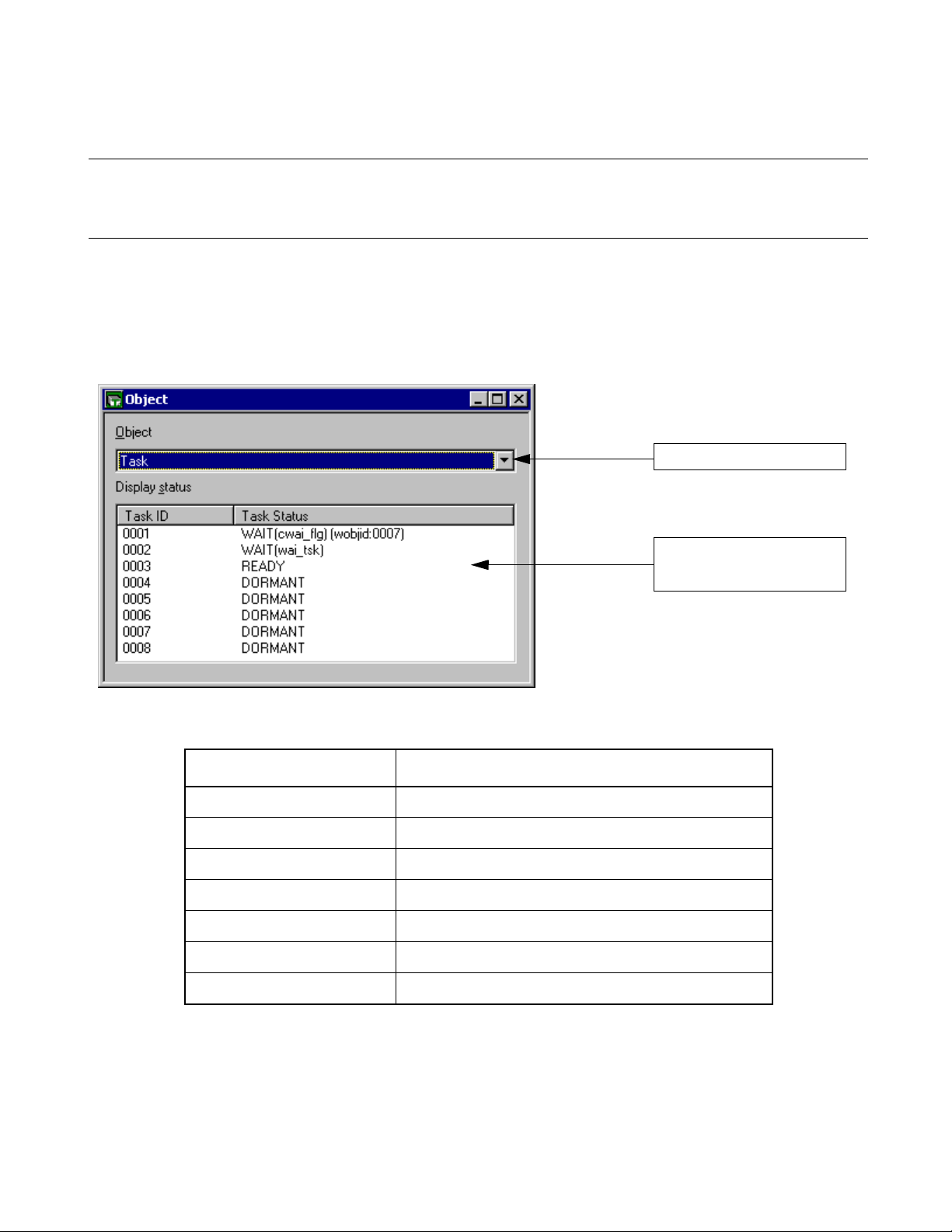
CHAPTER 3 Windows
3.16 Object Window
The Object Window displays the object information used by REALOS. This window is
displayed only when SOFTUNE WORKBENCH is in the debug session.
■ Object Window
The Object Window displays the object information used by REALOS.
Figure 3.16-1 is an example of the Object Window.
Figure 3.16-1 Example of Object Window
An object is selected.
■ Object/State Display
Object Status display
Task Task ID, task state
Semaphore Semaphore ID, count of semaphores
Flag (1-bit flag) Flag ID, SET or CLEAR
Mail box Mail box ID, count of message queues, count of tasks
Cyclic handler Handler ID, active state (residual time till activation)
Ready queue Priority, count of tasks
Timer queue Task ID or cyclic handler ID
Information for the selected
object is displayed.
85
Page 98

CHAPTER 3 Windows
■ Shortcut Menu
- Task Executes task system calls
- Semaphore Executes semaphore system calls
- Event Flag Executes event flag system calls
- Mail Box Executes mail box system calls
- Ready Queue Executes ready queue system calls
- Cyclic Handler Executes the system calls related to the cyclic handler.
- Monitoring Switches whether to enable or disable monitoring
- Property Displays object properties
- Close Closes Object Window
For details on the above items, see Section 4.4.11 Object.
86
Page 99

CHAPTER 3 Windows
3.17 Coverage Window
The Coverage Window displays the coverage measurement result. This window is
displayed only when SOFTUNE WORKBENCH is in the debug session.
■ Coverage Window
Figure 3.17-1 is an example of the Coverage Window. The Coverage Window displays the coverage
measurement result at debugging. This window is displayed only in MB2141 (emulator).
For details on the coverage function, see Section 4.4.12 Coverage.
Figure 3.17-1 Coverage Window (16-Address Unit)
Display tab. This
line is not scrolled.
Measured address Coverage rate
Measured address Coverage rate
Count of access
. : Unaccessed
1 to F : Accessed count of in 16 addresses
* : All 16 addresses were accessed.
Figure 3.17-2 Coverage Window (1-Address Unit)
Count of access
. : unaccessed
- : addressed
Display tab. This
line is not scrolled.
87
Page 100

CHAPTER 3 Windows
■ Shortcut menu
- Refresh Refresh Coverage Window display.
- Jump Opens the jump dialog box.
- 16 Address Unit Displays the coverage measurement result in the unit of 16 addresses.
- 1 Address Unit Displays the coverage measurement result for each address.
- Set See Section 4.4.12 Coverage.
- Total Coverage Rate See Section 4.4.12 Coverage.
- Clear Clears the coverage measurement buffer.
- Close Closes the Coverage Window.
88
 Loading...