

Page 1
OWNER'S MANUAL
We appreciate your purchase of this product.
Please read through this manual for correct operation.
We suggest that after reading it you keep this manual
in a safe place for future reference.
8 - DISC CD CHANGER
MODEL CH3083
Page 2
2
For your safety in using the
CH3083
Warnings and caution signs, illustrated below, are posted
throughout this manual as well as on the CH3083. They show
safe and correct ways to handle the product so as to prevent
personal injury to you and others and avoid damage to property.
Before reading through the manual, take time to read through
and learn the important information listed in this section.
This sign indicates a situation in which
incorrect handling through disregard of a sign
might result in death or serious personal
injury.
This sign indicates a situation in which
incorrect handling through disregard of a sign
might result in personal injury or may result
solely in damage to property.
•
Do not modify this system for use other than that specified
herein. Also, do not deviate from the installation procedures
described herein; Eclipse will not be held liable for damages
including, but not limited to serious injury, death or property
damage resulting from installations that enable unintended
operation.
•
This unit is intended for operation in DC 12-volt, negativegrounded vehicles only. Never use it in 24-volt vehicles such
as heavy trucks or diesel cars with cold-region specifications.
•
Do not change CDs while driving. Doing so may result in an
accident.
Warning
Caution
Warning
Page 3

3
•
Do not place the vinyl storage bag over a person. It may
cause a serious accident or death by suffocation.
•
Do not disassemble or rebuild this product. Doing so may
cause an accident, fire or electrical shock.
•
When it is necessary to replace the fuse, always use a fuse of
the correct rating (number of amperes). Use of fuses with
higher amperage ratings may cause a fire.
•
Do not operate the product in a malfunctioning condition, for
instance, when the audio does not play. Doing so may result
in an accident, fire or electrical shock.
•
If an abnormal situation occurs, such as foreign matter
entering or liquid splashing on the product, or smoke or a
strange odor emitting from the unit, shut off the product
immediately and consult the dealer from whom you purchased
it. Continued operation may cause an accident, fire or
electrical shock.
•
Do not install this product in locations where it may interfere
with the operation of the steering wheel, shift lever, brake
pedal, etc. Otherwise, an accident or injury may result.
•
To prevent damaging the vehicle, confirm the locations of
hoses, electrical wiring, and the fuel tank prior to drilling holes
to install this product. Also, take care so that the product does
not interfere, nor come in contact with them. Otherwise, a fire
may result.
•
When installing this product, never use the existing nuts or
bolts that secure parts of the fuel tank, or the steering or
braking system. Otherwise, improper steering or braking or a
fire may result.
Warning
Page 4

4
•
To prevent a short circuit from occuring, disconnect the
battery's negative terminal before installing this product.
Otherwise, an electric shock or injury may result
•
When using an existing nut and/or bolt from the vehicle to
ground this product, do not use any that secure parts of the
steering or braking systems. Otherwise, an accident may
results.
•
Bundle cables and harnesses with electrical tape or wire ties
to prevent them from interfering with moving parts. If they
should entangle the steering wheel, shift lever or brake pedal,
an accident may result.
•
Never supply power to another electrical appliance by splicing
or tapping into this product's power lead(wire). Otherwise, the
current capacity of the wire will be exceeded, resulting in a fire
or electric shock.
•
When making holes using a drill or similar tool, be sure to wear
protective eyewear. Otherwise, an injury such as loss of
eyesight may result.
•
Exposed wires must be insulated with electrical tape.
Otherwise, a short circuit, fire, or electric shock may result.
Warning
Page 5

5
•
Play the audio at a moderate volume level that permits you to
hear sounds from outside the car. Driving without being able
to hear outside sounds may result in an accident.
•
Keep foreign objects out of the disc slot. They may cause fire
or electrical shock. Another possibility is that discs may be
damaged or become stuck.
•
Do not stick your fingers or hands into the CD changer
magazine slot. Doing so may cause personal injury.
•
This product must be operated only as on-board equipment,
or it may cause electrical shock or injury.
•
Do not play distorted sounds for long periods of time;
the speakers may overheat and cause a fire.
•
This product uses an invisible laser light. In case a problem
develops, be sure to consult the dealer from whom you
purchased the product. Do not disassemble or rebuild the
unit; rebuilding it may expose you and others to a dangerous
laser emission which would damage eyesight or cause an
accident.
•
For best results, this product should be installed by a
professional installer. Contact the dealer whom you purchased
the product for an appointment.
•
When installing this product, be sure to use the supplied
mounting hardware. If parts other than those supplied are
used, the unit may be damaged internally, or may not be held
in place securely and become dislodged.
•
Avoid installing this product in places where it may get wet,
such as near windows, or in places that are moist or dusty.
Presence of liquid, moisture or dust inside this product can
cause short circuiting, resulting in smoke or fire.
Caution
Page 6
6
•
Do not install this product in locations where it cannot be
fastened securely, such as places subject to frequent
vibration. Otherwise, it may become dislodged and cause an
accident or injury.
•
If this product is not connected properly, a short circuit, fire or
accident may occur.
•
When routing cables, use care so that they do not contact
sharp metal parts such as brackets or screw tips. Otherwise,
a short circuit, electric shock, fire or accident may result.
•
If this product is operated for an excessive period of time, it
may overheat, resulting in a fire. Install the Product so that
heat may dissipate.
•
Do not obstruct the vent on this product. If blocked, excessive
heat build-up may occure and cause a fire.
•
A CLASS 1 LASER PRODUCT label is affixed to the top of
this unit.
Caution
Page 7

7
This CD changer allows you to select and play continuously your
desired tunes from 8 discs placed in the magazine.
Table of Contents
Operating precautions ................................................ 8
Notes on operation ........................................................................ 8
About compact discs .................................................................... 9
About cleaning a CD ................................................................... 11
Preparation ................................................................ 12
How to place the disc into the CD magazine ............................... 12
How to place the CD magazine into the changer ......................... 13
How to eject the CD magazine .................................................... 14
Specifications ............................................................ 15
Before Installation ..................................................... 16
Components ............................................................................... 16
Preliminary instruction .................................................................. 17
Daisy chain connection ................................................................ 18
Mounting instruction ................................................. 19
Horizonal instruction .................................................................... 19
Vertical instruction ....................................................................... 23
Connections ................................................................................ 26
System ........................................................................................ 27
Page 8
Operating precautions
Your CH3083 will perform well over a long period of time through correct
handling and care.
• For your safety, play only at volume levels that allow outside sounds to
be heard.
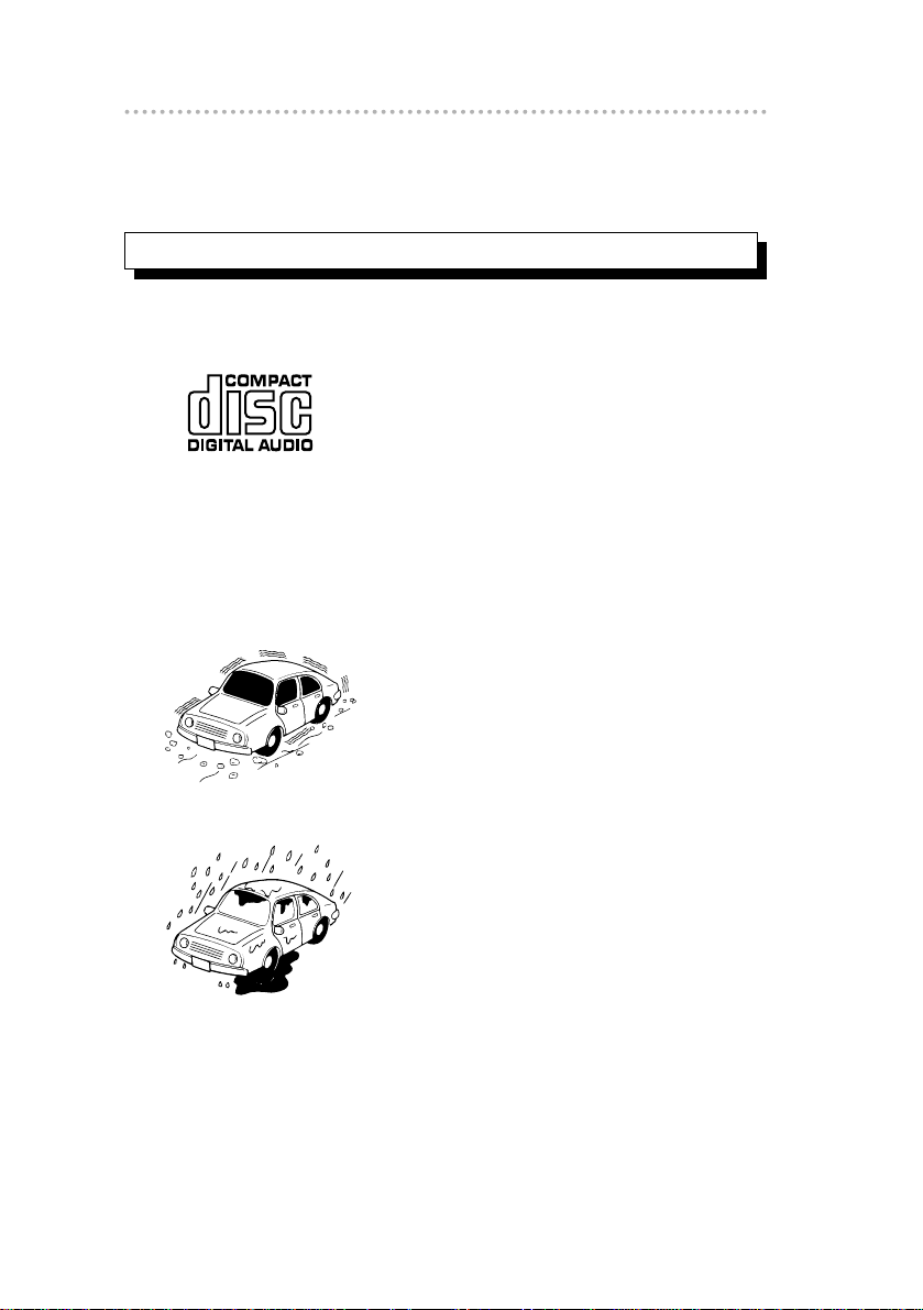
• We recommend using with this player a disc
with the logo shown to the left.
• You can play music CDs(CD-R/CD-RW) on
this player. Be sure to use discs that have
been properly processed.
• Depending on the editing equipment used,
some discs may not play properly.
• You cannot play MP3 CD-R/CD-RW discs
on this player.
• Avoid severe mechanical shock.
When the player is subjected to severe
vibration while traveling over a rough
surface, playback may be intermittent.
When a situation like this occurs, resume
playback after returning to a smoother
road.
• About dew condensation.
In cold or rainy weather, just as the interior
glass surface gets fogged, dew (water
condensation) may also settle on the deck.
When this occurs, disc playback may
become intermittent or impossible.
Dehumidify the air in the vehicle for a while
before resuming playback.
Notes on operation
Operating precautions
8
Page 9
9
Operating precautions
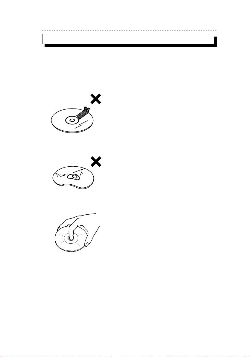
• The signal recorded on a compact disc is read by a laser beam, so
nothing touches the disc surface. A scratch on the recorded surface or
a badly warped disc may cause deteriorated sound quality or
intermittent playback. Observe the following precautions to ensure high
quality sound performance:
• Do not stick a piece of paper or tape on,
nor write on or scratch either side of a
disc.
• Discs spin at a high speed inside the
deck. Keep cracked or warped discs out
of the player to avoid damaging it.
• Avoid touching the recorded surface when
handling a disc; handle discs by their
edges.
About compact discs
Page 10
About CD accessories
• Do not use accessories
(stabilizers, protective seals, laser
lens cleaners, etc.) sold for
“improving sound performance”
or “protecting CDs.” The
changes in CD thickness or
outside dimensions made by
these accessories may cause
problems in the player.
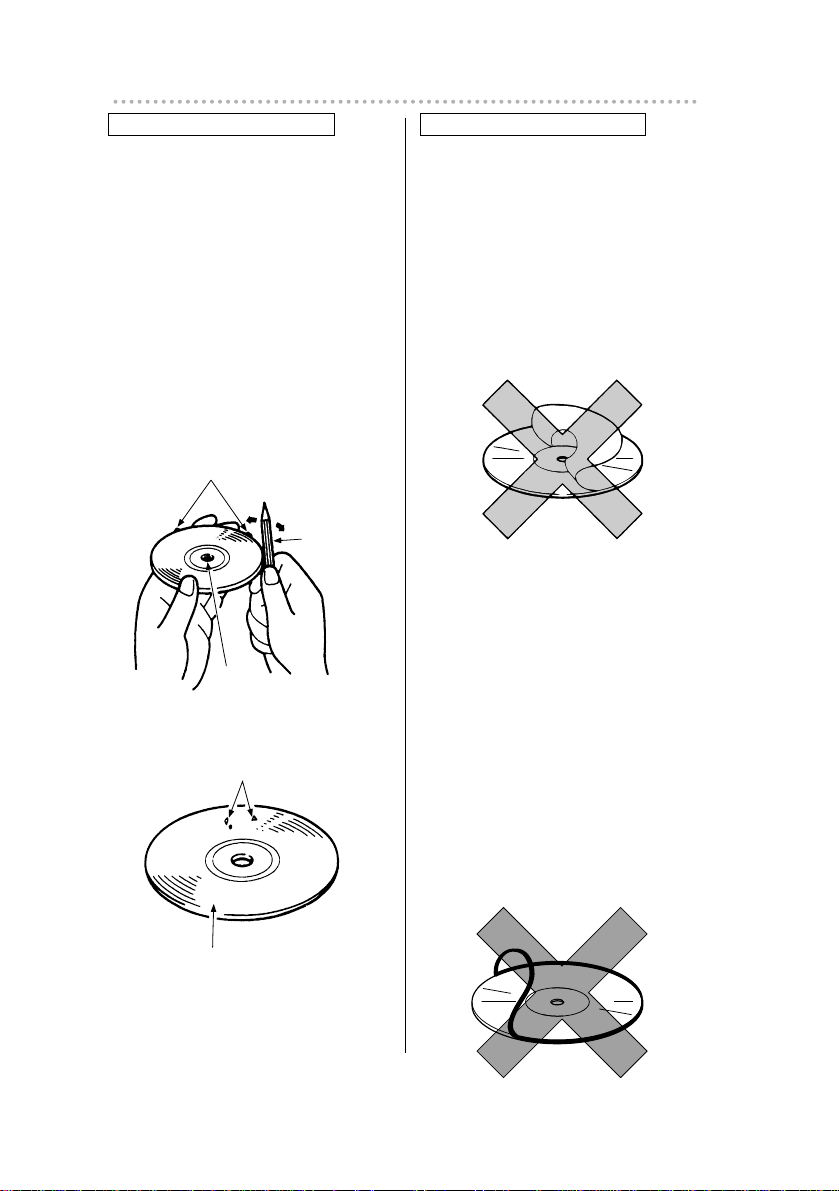
About brand new CDs
• You may notice that some brand
new discs are rough around the
center hole or outside edge.
Remove the rough edges with
the side of a ballpoint pen, etc.
Rough edges may prevent
proper loading in the deck.
Flakes from the rough edges
may also stick to the recorded
surface and interfere with
playback.
Rough Edges
Ballpoint
pen
Flakes
Recorded surface
Rough
Edges
• Please be sure NOT to attach any
ring-shape protector (or other
accessory) to your discs. Those
protectors are commercially
available and said to protect disc
and to improve sound quality
(and antivibration effect), but they
can do more harm than good in
regular uses. The most common
problems are Insert/Eject related
problems and "No playback"
problems due to the protectorring
that came off in the disc
mechanism.
Operating precautions
10
Page 11

11
Operating precautions
About borrowed CDs
• Do not use a CD with glue or
remnants of adhesive tape or
labels. They may cause the CD
to get stuck inside or damage
the deck.
About irregularly-shaped CDs
• Specially-shaped CDs, like
heart-shaped or octagonal CDs,
cannot be played. Do not
attempt to play them, even with
an adapter, since they may
damage the player.
• Use a commercially available compact disc
cleaner to clean a CD, wiping lightly from
the center to the edge.
• Do not use benzine, thinner, LP record
spray or other cleaners on CDs. They may
damage a CD’s finish.
XXXX
XXXX
XXXX
About cleaning a CD
PRECAUTIONS FOR THE CD MAGAZINE
• Do not place the CD magazine on hot place exposed to the sun or in
humid conditions. During summer, the temperature is very high on the
seat or dashboard of a completely closed car. So never leave the CD
magazine in such places.
• Do not drop the CD magazine or treat it roughly.
Page 12

Preparation
When you listen to a CD with this CD auto changer, please proceed as
follows before playing the CD.
■
How to place the disc into the CD magazine
• Slide a tray out of the CD
magazine.
• Place the CD on the tray with the
labeled side facing up.
• Slide the tray completely back
into the magazine. Otherwise it
may cause failure.
Preparation
12
The magazine holds up to eight
CDs.
It is not necessary to fill all eight
trays. Empty trays are ignored
when played.
Make sure that the tray seats
correctly along the guides on
both sides. Otherwise it may
cause failure.
1
2
3
Fix the index label to this surface
Labeled side up
CD magazine
Unloading knob
Disc tray
Page 13

13
Preparation
■ How to place the CD magazine into the
changer
• Slide the CD changer door
completely open to the left.
• Load the magazine into the
CD changer in the direction of
the arrow on the top of the
magazine.
• Slide the CD changer door to
the right to close.
Note: You cannot start playing unless the door is fuliy
closed.
V
H
M
4x5m
mM
AX
V
H
M
4x5m
m
M
AX
V
H
M
4x5m
m
M
AX
NEVER insert coins, screw drivers or anything other than the
magazine into the magazine slot.
1
2
3
Page 14

Preparation
14
■ How to eject the CD magazine
• Slide the CD changer door
completely open to the left.
• press the eject button on
the changer to eject the
magazine.
Note: The CD magazine will not be ejected if the door is not
completely open.
V
H
M
4x5m
m
M
AX
V
H
M
4x5m
m
M
AX
About CD MAGAZINE
• Use only the specified CD magazine.
• Up to eight trays (CDs) can fit in the CD magazine.
• When inserting a tray into the CD magazine, make sure that the trays
fit correctly into the racks of the magazine.
• Do not insert two or more CDs into a single rack, otherwise damage
may result.
• Contact the place of purchase for details on the CD-ROM discs that
can be played back using this unit.
1
2
Page 15

15
Specifications
◆
Specifications
System Compact Disc Digital Audio System
Decoding (D/A) 1bit dual D/A converter
Dynamic range 95dB or more(1kHz)
S/N (IHF-A.1kHz) 95dB
Harmonic distortion ratio 0.01% at 1kHz
Wow/flutter Below measurable limits
Nominal output level 2.0V RMS (0dB)
Line voltage DC 13.2V (11 to 16V)
Current consumption
about 1.8A max. and less than 600mA
during play.
Dimensions (W x H x D)
(230 x63 x185mm)
Weight 1.6kg (main unit), 0.2kg (magazine)
Note: The parts constants and circuit are subject to changes
without prior notice for performance improvements.
9x"
1
16
2x"
31
64
7"
9
32
Page 16

Before installation
16
◆
Before installation
Notes
Be sure to disconnect the vehicle battery's negative
terminal before installing CD changer unit.
■ Components
No. Item Q'ty
1 CD changer unit 1
2 Base bracket 1
3 Side bracket 2
4 Hex bolt (4x8mm) 4
5 Hex nut (5mm) 4
6 Self-adhesive pad 3
7 Cap 4
8 Din cable (13P-13P) 1
9 Interconnecting cable 1
10 Disc magazine, 8 discs 1
Page 17

17
Before installation
■ Preliminary instruction
Before CD changer unit installation, be sure to remove
CAUTION LABEL and TAPE.
Notes
In the event that the unit requires shipping, re-insert the
shipping screws through the caution tag template to help
prevent potential damage that may be caused by shipping.
V
H
Fig.1
CD CHANGER UNIT
1
CAUTION LABEL
TAPE
Page 18

Before installation
18
■ Daisy chain connection
Another CH3083 CD changer can be connected directly to your
CH3083 CD changer in daisy chain.
Both of these CD changers can be connected through the
control unit.
Notes
This switch is set to "H" before shipment.
Position of switch
Combination
Main unit + CH3083 (A) + CH3083 (B)
Other than the above
(combination without CD changer)
CD changer (A)
CH3083
"L" side
CH3083
"H" side
"H" side
CD changer (B)
M
4
x
5
m
m
M
A
X
V
H
HL
HL
Daisy Chain
selection switch
CD CHANGER
1
Page 19

19
Mounting instruction
◆
Mounting instruction
■ Horizonal instruction
1 .
Make sure levers on each side of CD changer unit
are in the "H" position.
NOTE: This levers is set to "H" before shipment.
M4x5mmMAX
V
H
V
H
Fig.2
CD CHANGER
1
Page 20

Mounting instruction
20
2 .
Secure the side brackets on each side of CD
changer unit.
Notes
• Use the "LH" holes (2 places) at the left of the side bracket
to install the unit.
• Use the "RH" holes (2 places) at the right of the side
bracket to install the unit.
LEFT RIGHT
LH
RH
RH LH
VV
LH
RH
RH LH
VV
V
H
Fig.3
CD CHANGER UNIT
1
SIDE BRACKETS [x2]
3
HEX BOLTS [x4]
(4x8mm)
4
Page 21

21
Mounting instruction
3 .
Lift the carpet, and choose the mounting location
by placing the base bracket in a safe location.
Remove the papers, then press the base bracket
on the floor panel securely.
4 .
Replace the carpet and cut x pattern thru carpet
where the mounting bolts appear. (Fig.5)
5 .
Push mounting bolts through a carpet. (Fig.6)
Fig.4
SELF-ADHESIVE PAD
6
BASE BRACKET
2
LIFT THE CARPET
REMOVE THE PAPER
Fig.6Fig.5
CARPET
CARPET
SCREW
Page 22

Mounting instruction
22
6 .
Install CD changer unit to the base bracket with 4 nuts
provided. Place caps over the mounting bolts.
V
H
M
4
x
5
m
m
M
A
X
Fig.7
CAPS [x4]
7
CD CHANGER
1
BASE BRACKET
2
NUTS [x4]
(5mm)
5
Page 23

23
Mounting instruction
■ Vertical instruction
1 .
Make sure levers on each side of CD changer unit
are in the "V" position.
NOTE: This levers is set to "H" before shipment.
M
4
x
5
m
m
M
A
X
V
H
V
H
Fig.8
CD CHANGER
1
Page 24

Mounting instruction
24
2 .
Secure the side brackets on each side of CD
changer unit.
Notes
• Use the "V" holes (2 places) of the side bracket to install
the unit.
LH
RH
RH LH
VV
COMMON TO RIGHT AND LEFT
V
H
Fig.9
CD CHANGER
1
SIDE BRACKETS [x2]
3
HEX BOLTS [x4]
(4x8mm)
4
Page 25

25
Mounting instruction
3 .
Lift the carpet, and choose the mounting location
by placing the base bracket in a safe location.
Remove the papers, then press the base bracket
on the floor panel securely.
4 .
Replace the carpet and cut x pattern thru carpet
where the mounting bolts appear. (Fig.11)
5 .
Push mounting bolts through a carpet. (Fig.12)
Fig.10
SELF-ADHESIVE
PAD
6
BASE BRACKET
2
LIFT THE CARPET
REMOVE THE PAPER
Fig.12Fig.11
CARPET
CARPET
SCREW
Page 26

Mounting instruction
26
6 .
Install CD changer unit to the base bracket with 4 nuts
provided. Place caps over the mounting bolts.
■ Connections
Caution
To prevent electrical damage to audio unit, be sure to
ground chassis of external power amplifier to car's body.
• The chassis of an add-on amplifier must be properly
grounded to a nearest metal part of the car's body.
• If the amplifier's chassis is not grounded, the amp's
chassis may possibly generate unwanted electric voltage
(in reference to the car body ground) as the user
operates the audio system. And eventually, this may
possibly lead to an internal damage (electric damage) of
the audio head unit.
V
H
M
4
x
5
m
m
M
A
X
Fig.13
CAPS [x4]
7
NUTS [x4]
(5mm)
5
CD CHANGER
1
BASE BRACKET
2
Page 27

27
Mounting instruction
■ System
②
CD3413
CH3083 POWER AMP.
POWER AMP.
MAIN UNIT
CD CHANGER
①
CD3413
CH3083
MAIN UNIT
CD CHANGER
③
CD3413
CH3083
CH3083
POWER AMP.
POWER AMP.
MAIN UNIT
CD CHANGER
CD CHANGER
NOTE: Adjust the external amplifier's
input level.
Page 28

Mounting instruction
28
1) CD3413+CH3083
NON-FADER
FRONT
REAR
CH3413
ANTENNA PLUG
White
White/Black
Gray
Gray/Black
Green/Black
Purple
Purple/Black
Pink
Green
16P
13P
CELLULAR PHONE
(For mute)
TO GROUND
DIGITAL OUT
13P
2P
CH3083
TO TURN-ON LEAD OF EACH UNIT (Supply)
TO HEADLIGHT SWITCH (Illumination)
TO POWER ANTENNA RELAY (Supply)
TO BATTERY + 12V (Permanent Supply)
TO ACC (Power Supply)
Black
Black/White
Orange/White
Blue
Red
Yellow
Page 29

29
Mounting instruction
2) CD3413+CH3083+Power Amplifier
NON-FADER
TO SIGNAL INPUT
OF AUXILIARY
POWER AMPLIFIER
CD3413
16P
13P
ANTENNA PLUG
INSULATE EACH
WIRE WITH TAPE
INSULATE EACH
WIRE WITH TAPE
White
White/Black
Gray
Gray/Black
Green/Black
Purple
Purple/Black
Pink
Green
CELLULAR PHONE
(For mute)
TO GROUND
Black
Black/White
Orange/White
Blue
Red
Yellow
TO TURN-ON LEAD OF EACH UNIT (Supply)
TO HEADLIGHT SWITCH (Illumination)
TO POWER ANTENNA RELAY (Supply)
TO BATTERY + 12V (Permanent Supply)
TO ACC (Power Supply)
DIGITAL OUT
13P
2P
CH3083
Page 30

Mounting instruction
30
3) CD3413+CH3083+CH3083+Power Amplifier
NON-FADER
CD3413
TO SIGNAL INPUT
OF AUXILIARY
POWER AMPLIFIER
16P
13P
ANTENNA PLUG
INSULATE EACH
WIRE WITH TAPE
INSULATE EACH
WIRE WITH TAPE
White
White/Black
Gray
Gray/Black
Green/Black
Purple
Purple/Black
Pink
Green
CELLULAR PHONE
(For mute)
TO GROUND
Black
Black/White
Orange/White
Blue
Red
TO TURN-ON LEAD OF EACH UNIT (Supply)
TO HEADLIGHT SWITCH (Illumination)
TO POWER ANTENNA RELAY (Supply)
TO ACC (Power Supply)
Yellow
TO BATTERY + 12V
(Permanent Supply)
DIGITAL OUT
13P
2P
CH3083
DIGITAL OUT
13P
2P
CH3083
(A)
(B)
NOTE: The switch on the back sicle of CD change (A) must be set to the "L" position
The switch on the back sicle of CD change (B) must be set to the "H" position
Page 31

Page 32

CUSTOMER NOTICE
Please retain this booklet and write in the serial number of your CH3083 for
identification.
The serial number is labeled or stamped on the chassis.
Serial No.
090001-1433A700
0508(N.O.)
DIVISION OF FUJITSU TEN CORP. OF AMERICA
19600 SOUTH VERMONT AVENUE, TORRANCE, CA 90502
(310) 327-2151
 Loading...