

Page 1
INSTRUCTION MANUAL
BEDIENUNGSANLEITUNG
MODE D’EMPLOI
MANUAL DE INSTRUCCIONES
English
INSTRUCTION MANUAL
CCD CAMERA
Deutsch
Français
CG-311 Series
Español
Page 2

DECLARATION OF CONFORMITY
according to EN45014
Fujitsu General Limited
Type: CCD CAMERA
Model Name: CG-311 Series
1116 Suenaga, Takatsu-ku, Kawasaki, Japan
Manufacturer:
declares under our sole responsibility that the product,
to which this declaration relates are in conformity with the following standards;
European Standards:
EMC : a. EN55022: 1998/A1: 2000
b. EN61000-3-2: 2000
c. EN61000-3-3: 1995/A1: 2001
d. EN50130-4 1995/A1: 1998
Safety : e. EN60950: 2000
By conformance with the standards referenced, the product follows
the provisions of the directives listed below.
Fujitsu General Limited
1116 Suenaga, Takatsu-ku,
Kawasaki, Japan
of
We
a.~d. EC Council Directive 89/336/EEC of 26th, March 2003
e. EC Council Directive 73/23/EEC of 14th, March 2003
Place of Issue: Japan
Date of Issue : May 2004
Signature:
T.Kishi, General Manager
Fujitsu General Limited
Declaration Reference: Fujitsu General Limited
1116 Suenaga, Takatsu-ku, Kawasaki, Japan
Page 3
WARNING– TO PREVENT RISK OF FIRE OR
SHOCK, DO NOT EXPOSE THIS CAMERA
TO RAIN OR MOISTURE.
PRECAUTION:
¶ DO NOT REMOVE ANY COVER WHILE THE
CAMERA IS OPERATING.
¶ PAL: USE ONLY RECOMMENDED POWER
SUPPLY, 24 VAC (21.6 to 26.4 VAC) 50
Hz or 12VDC(10.8 to13.2VDC).
NTSC: USE ONLY RECOMMENDED POWER
SUPPLY, 24 VAC (21.6 to 26.4 VAC) 60
Hz or 12VDC(10.8 to13.2VDC).
CAUTION:
¶ LENS MOUNT OF THE CAMERA IS “CS”
MOUNT.
¶ CAMERA LENS MOUNT IS SHALLOW, SOME
CAMERA LENSES MAY BOTTOM OUT AND
DAMAGE TO THE CCD IMAGER.
¶ DO NOT TOUCH THE CCD GLASS SURFACE.
¶ THE CAMERA MUST BE INSTALLED NEAR A
SOCKET-OUTLET WHICH COULD BE EASILY
ACCESSIBLE.
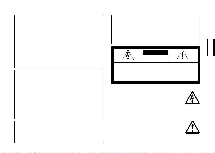
CAUTION
RISK OF ELECTRIC SHOCK
DO NOT OPEN
CAUTION:
TO REDUCE THE RISK OF ELECTRIC SHOCK, DO NOT
REMOVE COVER (OR BACK).
NO USER-SERVICEABLE PARTS INSIDE.
REFER SERVICING TO QUALIFIED SERVICE
PERSONNEL.
GRAPHIC SYMBOL EXPLANATION
The lighting flash with an arrowhead symbol within an equilateral
triangle is intended to alert the user
to the presence of uninsulated “dangerous voltage” within the product’s enclosure that may be of sufficient magnitude to constitute a risk
of electric shock to persons.
The exclamation point within an
equilateral triangle is intended to
alert the user to the presence of important operating and maintenance
(servicing) instructions in the literature accompanying the appliance.
En-1
Page 4

IMPORTANT SAFEGUARDS
1. Read Instructions–All the safety and operating instructions should be read before the
camera is operated.
2. Retain Instructions–The safety and operating instructions should be retained for future reference.
3. Heed Warnings–All warnings on the camera and in the operating instructions should
be adhered to.
4. Follow Instructions–All operating and use instructions should be followed.
5. Cleaning–Unplug the power unit from the
wall outlet before cleaning. Do not use liquid cleaners or aerosol cleaners.
Use a damp cloth for cleaning.
6. Attachments–Do not use attachments not
recommended by your appliance dealer, as
they may cause hazards.
7. Water and Moisture–Do not use the camera
in any location in which it may be exposed
to water or moisture.
En-2
8. Accessories–Do not place the camera on an
unstable cart, stand, tripod, bracket, or table.
The camera may fall, causing serious injury
to a child or adult, and serious damage to
the camera. Use only with mounting accessories recommended by your appliance
dealer or sold with the camera. Any mounting of the camera should follow your appliance dealer’s instructions.
8A. An appliance and cart
combination should be
PORTABLE CART WARNING
(Symbol provided by RETAC)
moved with care.
Quick stops, excessive
force, and uneven surfaces
may cause the appliance
and cart combination to
over turn.
S3125A
Page 5

9. Ventilation–The camera should never be
placed near or over a radiator or heat register.
The camera should not be placed in a builtin installation such as a bookcase or rack
unless proper ventilation is provided or your
appliance dealer’s instructions have been
adhered to.
10.Power Sources–The camera should be operated only from the type of power source
indicated on the rating plate. If you are not
sure of the type of power supply to your installation site, consult your appliance dealer
or local power company. For cameras intended to operate from battery power, or
other sources, refer to the operating instructions.
11.Power-Cord Protection–Power-supply cords
should be routed so that they are not likely
to be walked on or pinched by items placed
upon or against them, paying particular attention to cords at plugs, convenience receptacles, and the point where they exit from
the camera.
12.Lightning–For added protection for the camera during a lightning storm, or when it is
left unattended and unused for long periods of time, unplug it from the wall outlet
and disconnect the cable system. This will
prevent damage to the camera due to lightning and power-line surges.
13.Overloading–Do not overload wall outlet
and extension cord, as this can result in a
risk of fire or electric shock.
14.Object and Liquid Entry–Never push objects
of any kind into the camera through openings, as they may touch dangerous voltage
points or short-out parts that could result in
a fire or electric shock. Never spill liquid of
any kind on the camera.
15.Servicing–Do not attempt to service the
camera yourself as opening or removing
covers may expose you to dangerous voltage or other hazards.
Refer all servicing to qualified service personnel.
En-3
Page 6

16.Damage Requiring Service–Unplug the
power unit from the wall outlet.
Refer servicing to qualified service personnel under the following conditions.
a. When the power-supply cord or plug is
damaged.
b. If liquid has been spilled, or objects have
fallen into the camera.
c. If the camera has been exposed to rain or
water.
d. If the camera does not operate normally
by following the operating instructions.
Adjust only those controls that are covered by the operating instructions, as an
improper adjustment of other controls
may result in damage and will often require extensive work by a qualified technician to restore the camera to its normal operation.
e. If the camera has been dropped or the
cabinet has been damaged.
f. When the camera exhibits a distinct
change in performance. This indicates a
need for service.
En-4
17.Replacement Parts–When replacement parts
are required, be sure the service technician
has used replacement parts specified by
qualified dealer or that have the same characteristics as the original part.
Unauthorized substitutions may result in
fire, electric shock or other hazards.
18.Safety Check–Upon completion of any service or repairs to the camera, ask the service technician to perform safety checks to
determine that the camera is in proper operating condition.
Page 7

INTRODUCTION
Thank you for your purchasing this color camera. Read this installation and instruction
manual thoroughly before using, and operate
the camera properly.
This color camera has functions which employ
a high density image sensor and ensure a sharp
and clear picture even with dark and bright
portions in a scene by improving dynamic
range.
It can be used in the wide range of CCTV systems as it is provided with various functions
such as wide dynamic range function, automatic sensitivity adjustment, real time auto
white balance, and auto iris lens output.
Outstanding features are as follows,
1. This camera provides clear image under even
bright and dark scenes by increasing dynamic range of image signal comparing with
conventional camera.
2. Even the back light is strong, we can get a
good image without extremely white or
blacked out portions of images by applying
a technology which composes with dark image and bright image.
3. Compact size is accomplished by our high
density design and mounting technologies.
4. 380K/440K pixels and 1/3 inch CCD accompanies with high resolution imaging.
CAUTIONS FOR OPERATION
* Do not touch the photoconductive surface
of the CCD imager element. Scratches may
occur.
If dust sticks on the surface, wipe it off softly
with a lens cleaning paper.
* Do not use this camera outdoors.
Avoid places where an inflammable gas or
a corrosive atmosphere exists.
* If the camera case becomes dirty, wipe off
with a soft dry cloth. For the large dirt on
the case, wipe it off using a soft cloth moistened a neutral detergent diluted with water
and wipe again with the dry cloth. Never use
alcohol, benzine or other volatile solutions.
* Don’t image excessive light sources (sun-
light etc.) for many hours.
If CCD imager element is exposed to ultraviolet rays for many hours, the filter colour
on the surface of CCD imager element fades.
Don't image sunlight or illumination directly,
when a camera is left as it is.
Don't image sunlight or illumination directly,
even if the power is turned off.
* White spots may appear on the screen. How-
ever this is not a failure.
With standard lenses the focus can shift
under IR light conditions.
To avoid this, we recommend to use special lenses with no focus shift.
En-5
Page 8
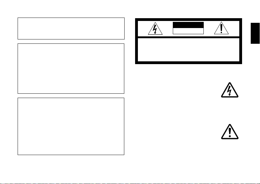
EXTERNAL CONTROLS AND
CONNECTIONS
REAR VIEW
1
2
VIDEO
L E N S
L E V E L
3
6
7
O F F
AGC
ESC
BLC
ECLP
DC12V
24VAC
O N
AWB
SYNC
D/N
FL
THRE ECLP GRAY
BOTTOM VIEW
9
8
En-6
Fig. 1
11
1 Lens Connector (Small 4 pin)
11
22
2 Video Output Connector (BNC)
22
33
3 Level adjuster
33
44
4 LL ADJ. Swith:UP
44
55
5 LL ADJ. Swith:DOWN
55
66
6 DIP Switch
66
77
7 Power Input Terminal
77
88
8 Back Focus Lock Screw
4
LL
UP
DOWN
5
-0
=
88
99
9 Lens Mount
99
00
0 THRESHOLD level adjuster
00
--
- ECLIPSE level adjuster
-==
= GRAY level adjuster
==
~~
~ Camera Mount (1/4"-20 tapped hole)
~~
CAMERA MOUNT
~
Mountable on top or bottom of the camera.
CAUTION:
Improper installation may cause the camera to fall,
resulting in injury. Please ask qualified service
personnel for installations.
To reduce the risk of electric shock and other
injuries, please lay out cables where there is no
danger of damage or where people can not touch
by accident.
Page 9

21
43
LENS
The camera can accommodate a wide selection of lenses, these lenses include manual iris
lenses (see ESC FUNCTION), DC controlled iris
lenses, and “Standard” video controlled iris
lenses.
A. ELECTRICAL CONNECTIONS
Table 1 shows two different wiring schemes
for the 4pin Auto-iris connector.
If a “Standard” auto-iris is to be used, see “(1)
VIDEO SIGNAL CONTROL”. (Table 1)
For DC controlled iris, use “(2) DC VOLTAGE
DRIVE”.
CAUTION:
The output power for auto-iris lens is +9 VDC and the
maximum current capacity is 40 mA.
When using an auto-iris lens requiring voltage and
current other than specified, supply lens power only
from an external power supply.
Set the Esc switch (#2 switch of Dip Switch) to “OFF“
when using an auto-iris lens type.
Lens Connector Auto-iris Lens
(View from wiring side of plug)
Fig. 2
Table 1
AUTO-IRIS LENS
Connector
Pin No.
(1) VIDEO SIGNAL
1
+9 VDC (40 mA max.)
+9 VDC (40 mA max.)
2
AI-VIDEO
3
GND
4
CONTROL
(2) DC VOLTAGE
DRIVE
CONT. (–)
CONT. (+)
DRIVE (+)
DRIVE (–)
En-7
Page 10
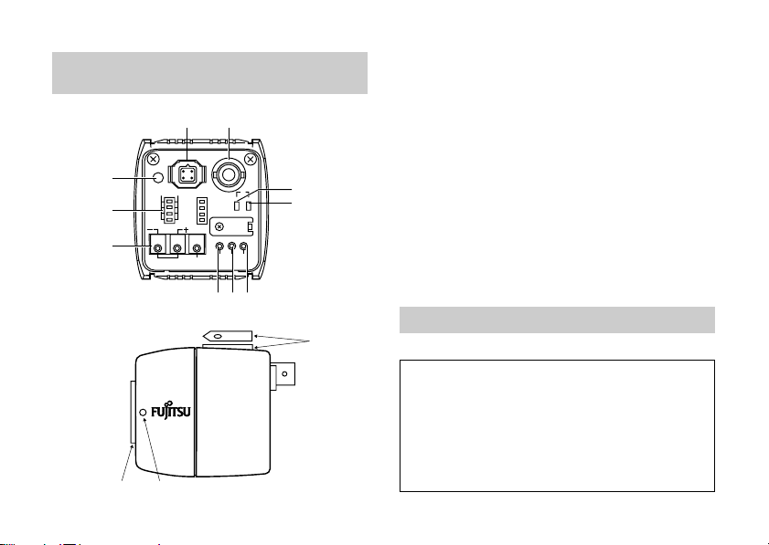
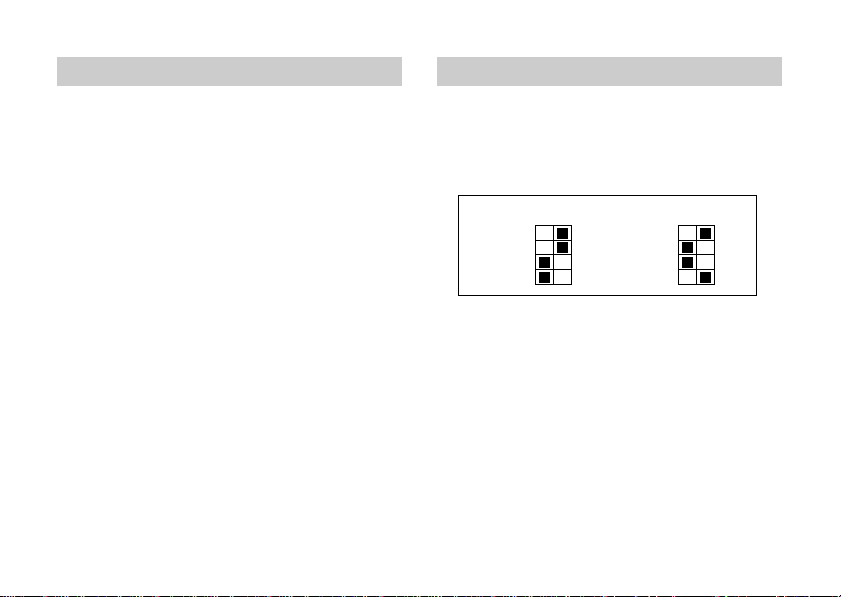
B. MECHANICAL CONNECTION
Before mounting any lens onto this camera,
check that the rear lens dimensions do not exceed the following maximum length, otherwise
CCD imager could be damaged.
“X”
CS = 0.2" (6 mm)
C = 0.4" (10 mm)
The camera is shipped, ready
to accept “CS“ type lens.
If standard “C“mount lens
are to be used, it is necessary
to install the“C-mount Adapter“
ring first, then the lens.
LENS
Fig. 3
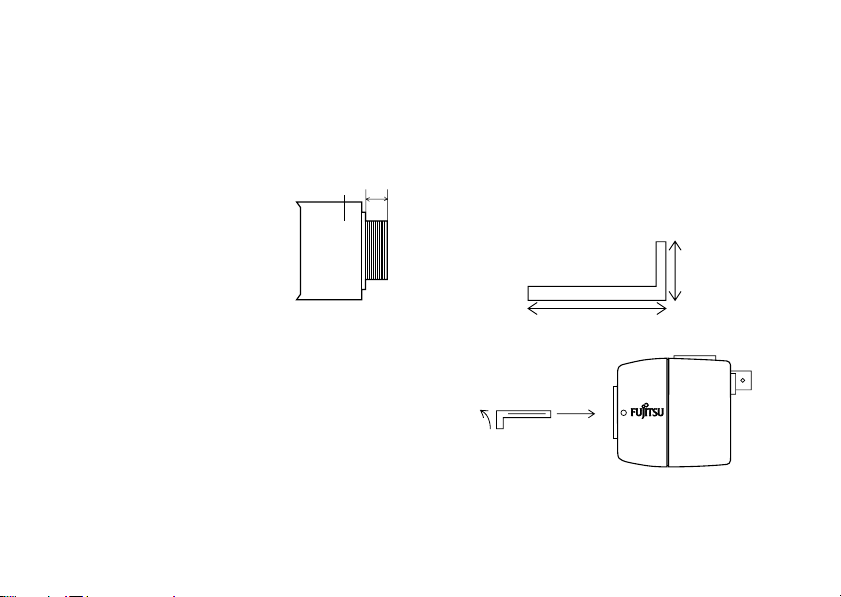
C.BACK FOCAL LENGTH ADJUSTMENT
The camera has been factory-adjusted for the
proper back focal length using a standard CS
Mount lens. However, when the lens is mounted,
it may be necessary to readjust back focal length
to match the lens being used.
En-8
“X”
CAUTION:
If the back focus locking screw is tightened too strong,
the thread section of “Lens Mount” may be damaged.
To tighten the back focus locking screw, use a 1.5 mm
ALLEN WRENCH.
Hold the short side of the handle (as shown in Fig.4),
and turn it clockwise lightly to the stop position.
Turn a little more (approx. 15 degrees) from this
position.
ALLEN WRENCH
10 mm
50 mm
Approx. 15
CAMERA
Fig.4
Page 11

1. Fixed Focus Lens
¶ Mount the lens firmly on the camera.
¶ Set the lens focus ring to the infinity (∞)
position.
¶ Set the camera to view an object 30 feet
(10 m) or more.
¶ Make sure the lens iris is wide open.
¶ Loosen the back focus lock screw at the
side of the camera using a 1.5 mm ALLEN
WRENCH (turn it counterclockwise). See
Fig.1 for location.
¶ After checking that the lens focus ring is
in the “∞” position, turn the Lens Mount
to the point where the sharpest image is
seen on the monitor screen and tighten
the back focus locking screw clockwise.
2. Zoom lens
¶ With the camera in operation, view an
object at least 70 feet (25 m) away.
¶ Make sure the lens iris is wide open.
¶ Set LENS FOCUS to FAR position.
¶ Adjust lens ZOOM to WIDE angle. (Wide
field of view)
¶ Loosen the back focus lock screw at the
side of the camera using a 1.5 mm ALLEN
WRENCH.
Turn the lens mount to obtain the sharpest image on the monitor.
Then tighten the back focus locking
screw clockwise. (See Fig.1 for location.)
¶ Move lens ZOOM to TELEPHOTO. (Small-
est field of view)
¶ Adjust LENS FOCUS (by the controller)
for best picture.
En-9
Page 12

POWER CONNECTION
This camera uses 24VAC or 12VDC power supply for the main supply.
CAUTION:
Take care not to short-circuit the power line
wire, when connecting the power-supply
cord to the camera.
A. AC POWER CONNECTION
PAL: A main supply of 24VAC (21.6 to 26.4 VAC)
50Hz is required.
NTSC: A main supply of 24VAC (21.6 to 26.4 VAC)
60Hz is required.
This main supply must also have a minimum
rating of 270mA.
Remove the sheath at the end of power cord in
the length of 10mm.
Twist and straighten the wires, then insert the
wires to three holes of the terminal.
If the insertion can not be made smoothly, try
it again while pushing respective button above
the hole.
En-10
CAUTION:
Confirm that the cord is connected to the
terminal securely by pulling the cord.
Confirm that there is no whisker of wires
outside the holes of terminal.
Connect to 24VAC class 2 power supply only.
Make sure to connect the grounding lead to the
GND terminal when the power is supplied from a
24VAC power source.
CAUTION:
When two or more cameras are used by
one transformer, use a transformer having
the rated current more than the current
consumed with the number of cameras ×24VAC 270
mA.
TRANSFORMER
INPUT
OUTPUT
REAR PANEL
AC 24 V
Button
Fig.5
Page 13

B. DC POWER CONNECTION
CAUTION:
DC power supply must be marked with a CE symbol.
CAUTION:
If the power-supply cord is short-circuited, excessive current flows and is
extremely dangerous. The line fuse
must be required. (see Fig.6).
CAUTION:
¶ Be sure to wire the power plug polarity
correctly.
¶ Current consumption 390mA per camera
When selecting and connecting the power-supply
cord, take care concerning the following:
11
1 Current allowance of the power-supply cord.
11
22
2 Power supply voltage drop due to excessive
22
is required.
length or size of wire.
The rated power supply voltage of this camera
is +12VDC (+10.8 to +13.2VDC).
Be sure to use the camera within this range of
voltage.
Power supply connections are shown in Fig.6.
If a fuse is required, use a slow blow fuse connected to the + terminal of the power supply
within 10cm (4inch) of the terminal.
DC POWER
SUPPLY
FUSE (slow blow)
+12 V
GND
10cm (4.0 inch) MAX
1.0 A
REAR PANEL
Button
DC 12 V
Fig.6
En-11
Page 14
VIDEO OUTPUT
DIP SWITCH
BNC OUTPUT
The output of this connector is a composite
Video Signal. Use a high quality 75 Ω coaxial
cable between the camera and other video
equipment. At the “Video Equipment”end of
the coaxial cable, terminate the signal with a 75
Ω resistor.
En-12
#1: AGC OFF/ON #5: AWB
HOLD/AUTO
#2: ESC OFF/ON #6: SYNC AUTO/INT
#3: BLC OFF/ON #7: D/N
#4: ECLIPSEROFF/ON #8:
#1:
AGC
#2:
ESC
#3:
BLC
#4:
ECLP
NOTE: 7 is factory setup.
FLICKERLESS
#5:
AWB
#6:
SYNC
#7:
D/N
#8:
FL
AUTO/HOLD
ON/OFF
Fig. 7
Page 15

AGC FUNCTION
This function keeps the video output level of
the camera by varying the gain control automatically.
The AGC function switch can be turned ON/OFF
by moving #1 switch of Dip Switch right and
left.
(Factory setup is AGC ON.)
ELECTRONIC SENSITIVITY CONTROL (ESC) FUNCTION
This function changes the sensitivity of the
camera by varying the electronic shutter speed
according to the amount of incident ray.
ESC range; 1 : 300
The ESC function switch can be turned ON/OFF
by moving #2 switch of Dip Switch right and
left.
(Factory setup is ESC ON.)
CAUTION:
Set the FL Switch (#8 switch of Dip Switch) to “OFF“,
otherwise ESC function does not work.
BACK LIGHT COMPENSATION
(BLC) FUNCTION
The Back Light Compensation function allows
fine picture correction to prevent the subject
from being extremely dark due to strong backlight.
The BLC function switch can be turned ON/OFF
by moving #3 switch of Dip Switch right and
left.
(Factory setup is BLC OFF.)
CAUTION:
Set the AGC Switch (#1 switch of Dip Switch)
to “ON“ for BLC function, otherwise BLC
function does not work.
En-13
Page 16

ECLIPSER FUNCTION ECLIPSER ADJUSTER
When using a CCD camera with an auto-iris
lens, in a dark area with a light background not
enough contrast is obtained, since the background signal causes the auto-iris to close, resulting in unclear images. However, when the
ECLIPSER function is operated together with
an auto-iris lens, the light background signal is
sliced and converted into a gray level video signal. With this signal, the auto-iris lens is operated, so that the iris is opened and sufficient
contrast can be obtained.
The ECLIPSER function switch can be turned
ON/OFF by moving #4 switch of Dip Switch
right and left.
(Factory setup is ECLIPSER OFF.)
CAUTION:
The ECLIPSER function must be used with an autoiris lens. When the auto-iris lens to be used is equipped
with a response selector (AVERAGE/PEAk), always set
it to AVERAGE.
En-14
(VR802, VR803, VR804)
1. The ECLIPSER is factory adjusted with a
standard adjustment and the best results
should be obtain without readjustment.
However, to fine adjust eclipse THRESHOLD
level proceed as follows.
Refer to EXTERNAL CONTROLS AND CON-
*
NECTIONS
2. Set the position of DIP-SW
AGC : OFF
ESC : OFF
BLC : OFF
3. Setting of VR (Variable Resistors) and
switch:
(1) THRESHOLD VR: Counterclockwise
(2) ECLIPSE VR : Mechanical center
(3) GRAY VR : Mechanical center
(4) ECLIPSER SW : OFF
Page 17

4. Set response selector of auto-iris lens (Video
type) to AVERAGE.
Viewing gray scale (logarithmic) or an object, set video output level of camera to
0.75Vp-p (100IRE) by adjusting LEVEL VR of
auto-iris lens.
5. Set ECLIPSER SW (Dip Switch #4): ON.
Viewing highbright object, adjust THRESHOLD VR (VR802) by turning it clockwise so
as video output level of camera to be clipped
at 0.8~0.85Vp-p. (See Fig.8)
6. Set gray level shown in Fig.8 to 0.35Vp-p by
turning GRAY VR (VR804) to clockwise or
counterclockwise.
7. Viewing an object in front of a bright background, adjust the ECLIPSE VR (VR803) by
turning it clockwise or counterclockwise
until the object can be seen with good highlight and the background becomes gray.
(See Fig.9)
Gray level
0.8 ~ 0.85 Vp-p
0.35 Vp-p
Video signal
V
Fig.8
Gray background
Image on monitor
Fig.9
En-15
Page 18

AUTO WHITE BALANCE (AWB)
There are AUTO and HOLD in the white balance adjustment in this camera. The white balance is adjusted automatically to provide the
optimum picture just by setting the white balance selection switch to the AUTO. When you
do not obtain the optimum white balance in
AUTO, HOLD is used. At #5 switch of
Switch
.
Left side: HOLD
Right side: AUTO
(Factory setup is AWB AUTO.)
CAUTION:
This function is color mode only.
En-16
DIP
SYNCHRONIZATION MODE (SYNC)
LINE LOCK MODE
(The camera using the 24VAC power supply)
This mode allows the camera to use the phase
of the AC power as the reference.
When attempting to phase a group of cameras
together deviation from the AC power phase
may be required.
This can be done with the phase adjustable Line
Lock control.
(For the phase adjustment, refer to “L.L.
ADJUSTER”.)
INTERNAL MODE
(The camera using the 12VDC power supply)
In this mode, an inside crystal oscillator is used
as INT. Sync Generator.
The synchronization mode can be selected by
moving #6 switch of
The meaning of switch is as follows,
Left side: Auto mode(DC: Internal, AC: Line
Lock)
Right side: Internal mode
(Factory setup is SYNC AUTO.)
DIP Switch
right and left .
Page 19

DAY/NIGHT MODE (D/N)
There are two modes of AUTO and HOLD in
this camera at Day/Night mode.
The Day/Night operation works automatically
according to the brightness of subject in AUTO
mode.
When you prefer to maintain current state,
HOLD mode may be used.
At #7 switch of DIP Switch
Left side : AUTO
Right side : HOLD
(Factory setup is AUTO mode.)
CAUTION:
When using this camera with IR light or lighting where the color temperature is 3000 k or
less, this camera shifts automatically to night
mode.
Under unfavorable conditions (strength or
angle of illumination) it can happen that hunting occurs.
The CG-311 has a special circuit to prevent such
kind of hunting problems.
If the camera detects a hunting condition, the
night mode is maintained for 30 minutes.
Every 30 minutes the camera checks automatically whether the condition which caused hunting still exists and maintains if so for further 30
minutes.
To avoid this operation you have to adjust the
strength or the angle of the illumination.
FLICKERLESS (FL)
CAUTION:
This function is used under fluorescent light on
the power supply area with different frequency
from the camera scanning frequency.
Set the FL switch (#8 switch of DIP Switch) to
“OFF”, otherwise the flicker may occur.
(Factory setup is FL OFF.)
En-17
Page 20
LEVEL ADJUSTER (VR801)
This controller serves to adjust the video output level when DC Voltage Controlled Auto-Iris
Lens is used.
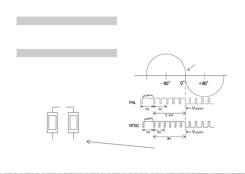
L. L. ADJUSTER
(The camera using LINE LOCK MODE)
The power supply synchronizing phase of each
camera is set to the same phase at the factory.
Usually, the power supply synchronizing phase
does not need readjustments.
The power supply synchronizing phase changes by pressing the LL ADJ. switch.
The dimension from the zero cross point of the
power supply voltage waveform to the deactivation point of Vsync of the odd field is 0° at
presetting.
ZERO CROSS POINT
En-18
S803
UP
LL
DOWN
S802
Fig. 8
DOWN}]UP
Page 21

SPECIFICATIONS
ITEM CG-311N CG-311P
TV System NTSC PAL
Power Supply 24VAC (±10%), 60Hz(NTSC), 50Hz(PAL) / 12VDC (±10%)
Current Consumption 270mA (24VAC)/390mA (12VDC)
Picture Elements (Active) Approx. 380K pixels Approx. 440K pixels
Video Output
Synchronization Line-Locked Sync. (24VAC) / Internal Sync. (12VDC)
Horizontal Resolution 480 TV lines 470 TV lines
Signal to Noise Ratio 48 dB (AGC OFF, weighting)
Minimum Scene
Illumination
Usable Auto Iris Lens
11
1 Video Signal Control Lens
11
22
2 DC Voltage Control Lens
22
Color mode : 1.0Lux (F1.2) / B/W mode : 0.1Lux (F1.2)
1.0Vp-p, Composite (VBS), 75 Ω / BNC Connector
En-19
Page 22

ITEM CG-311N CG-311P
Connectors REAR PANEL
11
1 Video Output
11
22
2 Auto-lris Lens Output
22
Controls REAR PANEL Adjustment
Switch
11
1 Phase (Vertical Phase) (push switch; UP and DOWN)
11
22
2 Level (DC drive Lens) (VR)
22
33
3 THRESHOLD level (VR)
33
44
4 ECLIPSE level (VR)
44
55
5 GRAY level (VR)
55
11
1 DIP SW
11
33
3 3P-Connector (Push in type)
33
1) AGC OFF/ON 5) AWB HOLD/AUTO
1
2) ESC *
3) BLC *
OFF/ON 6) SYNC AUTO/INT
2
OFF/ON 7) D/N AUTO/HOLD
4) ECLIPSER OFF/ON 8) FL ON/OFF
Ambient Temperature
(Temperature at which the
performance is guaranteed)
Dimensions
(Less lens and connector)
-10°C to 50°C
(0°C to 40°C)
53(W) x 55(H) x 56(D) mm
Weight (Excluding lens) 0.2 kg
Accessories (Supplied) 4 Pin plug (Small type) .............. 1 pc Instruction Manual .............. 1 pc
ALLEN WRENCH ........................ 1 pc CAMERA MOUNT ............... 1 pc
*1 ; Electronic Sensitivity Control Specifications are subject to change without notice.
*2 ;
Back Light Compensation
En-20
Page 23
SICHERHEITSHINWEIS– SCHÜTZEN SIE DIE
KAMERA GEGEN EINDRINGEN VON WASSER
UND FEUCHTIGKEIT. WASSER UND
FEUCHTIGKEIT KÖNNEN DIE GERÄ TE
DAUERHAFT SCHÄDIGEN UND BERGEN
DARÜBERHINAUS DIE GEFAHR EINES STROMSCHLAGES. SOLLTE DENNOCH FEUCHTIGKEIT
EINGEDRUNGEN SEIN, DARF DIE KAMERA
NICHT EINGESCHALTET WERDEN, SONDERN
MUSS ZUR ÜBERPRÜFUNG EINER AUTORISIERTEN FACHWERKSTATT ÜBERGEBEN WERDEN.
WARNUNG:
¶ NIEMALS NACH INBETRIEBNAHME DEN
DECKEL DER KAMERA ÖFFNEN.
¶ PAL:
BENUTZEN SIE AUSSCHLIESSLICH DIE
EMPFOHLENE SPANNUNGSVERSORGUNG
,
24VAC (21,6 bis 26,4VAC) 50Hz oder 12VDC
(10,8 bis 13,2VDC).
NTSC: BENUTZEN SIE AUSSCHLIESSLICH DIE
EMPFOHLENE SPANNUNGSVERSORGUNG
24VAC (21,6 bis 26,4VAC) 60Hz oder 12VDC
,
(10,8 bis 13,2VDC).
ACHTUNG:
¶ DER OBJEKTIVANSCHLUSS DER KAMERA
IST “CS-MOUNT”
DIE EINSCHRAUBTIEFE DES KAMERA-MOUNTS IST
NUR GERING. MANCHE OBJEKTIVE RAGEN ZU
WEIT IN DEN OBJEKTIVANSCHLUSS HINEIN UND
KÖNNEN SOMIT DEN CCD SENSOR BESCHÄDIGEN.
BERÜHREN SIE NICHT DIE CCD GLASOBERFLÄCHE.
DIE KAMERA MUSS IN DER NÄHE EINER LEICHT ZUGÄNGLICHEN NETZSTECKDOSE INSTALLIERT
SEIN.
VORSICHT
HOCHSPANNUNG
NICHT ÖFFNEN!
UM DAS RISIKO EINES ELEKTRISCHEN
VORSICHT:
STROMSCHLAGES ZU VERMEIDEN, DAS GEHÄUSE
NIEMALS ENTFERNEN. ES BEFINDEN SICH KEINE,
DURCH DEN BENUTZER REPARABLEN TEILE IM
INNEREN.
REPARATUREN AUSSCHLIEßLICH DURCH
QUALIFIZIERTES PERSONAL.
SYMBOLERKLÄRUNG
Der Blitz mit einer Pfeilspitze in einem gleichseitigen Dreieck weist den Benutzer auf eine,
im Kamerainneren vorhandene, nicht
isolierte “ Gefährliche Spannung” hin. Diese kann
ausreichend sein, um Personen einen elektrischen
Stromschlag zu versetzen.
Das Ausrufezeichen in einem gleichseitigen Dreieck weist den Benutzer auf
wichtige Bedienungs- und Wartungsanleitungen (Service) in den begleitenden
Unterlagen hin.
Ge-1
Deutsch
Page 24

WICHTIGE SICHERHEITSHINWEISE
1. Lesen der Bedienungsanleitung–Bevor Sie
die Kamera anschließen und in Betrieb
nehmen, lesen Sie bitte zuerst die Sicherheitshinweise und die Bedienungsanleitung.
2. Aufbewahren der Bedienungsanleitung–
Bewahren Sie die Bedienungsanleitung für
spätere Verwendung sorgfältig auf.
3. Warnhinweise–Sämtliche Warnhinweise auf
der Kamera sowie in der Bedienungsanleitung sollten befolgt werden.
4. Befolgen der Vorschriften–Sämtliche Bedienund Benutzervorschriften sollten befolgt
werden.
5. Reinigung–Zur Reinigung des Gerätes ziehen
Sie den Netzstecker aus der Steckdose.
Benutzen Sie keine flü ssigen
Reinigungsmittel oder Äthylalkohol. Benutzen Sie ein nur feuchtes Tuch zur Reinigung.
6. Befestigungen–Benutzen Sie nur vom
Händler empfohlene Befestigungen, da sonst
Beschädigungen nicht ausgeschlossen sind.
Ge-2
7. Wasser und Feuchtigkeit–Benutzen Sie die
Kamera nicht in feuchter oder nasser
Umgebung.
8. Zubehör–Plazieren Sie die Kamera nicht an
einer instabilen Stelle, Stativ, Wandarm oder
Tisch, da die Kamera herunterfallen könnte
und Kinder oder Erwachsene in ernsthafte
Gefahr bringen sowie selbst kaputtgehen
kö nnte. Benutzen Sie ausschließlich
empfohlenes oder von Ihrem Händler mit der
Kamera verkauftes Halterungszubehör.
Befolgen Sie bei jeder Befestigung die
Anweisung Ihres Verkäufers.
8A. Stative und Rollwagen
sollten vorsichtig bewegt
PORTABLE CART WARNING
(Symbol provided by RETAC)
werden. Schnelle Stops,
ruckartige Bewegungen und
unebene Standflächen
kö nnen zum kippen der
Stative oder der Rollwagen
führen.
S3125A
Page 25

9. Belüftung–Die Kamera darf niemals in der
Nähe oder über einer Heizung bzw. einem
Wärmestrahler plaziert werden.
Die Kamera darf nicht in einem Gehäuse,
Schrank oder Regal eingebaut, werden ohne
das für geeignete Belüftung gesorgt wird.
10.Spannungsquellen–Die Kamera darf nur mit
einer in den Betriebsdaten genannten
Spannungsquelle betrieben werden. Wenn
Sie sich der Betriebsspannung nicht sicher
sind, wenden Sie sich an den Händler oder
an das ortsansässige Energieversorgungsunternehmen. Für batteriebetriebene
oder ähnliche Kameras lesen Sie bitte in der
Bedienungsanleitung nach.
11.Netzanschlußkabelschutz–Netzanschluß-
kabel sollten so verlegt werden, daß nicht auf
sie getreten werden kann bzw. diese
gequetscht werden können. Achten Sie
besonders auf das Kabel an Steckern,
Steckdosen und der Kameraanschlußstelle.
12.Überspannungsschutz–Als zusäizlichen
Schutz für die Kamera während eines
Gewitters, wenn sie unbeaufsichtigt ist oder/
und für längere Zeit nicht benutzt wird, ziehen
Sie den Netzstecker und lösen Sie alle
weiteren Anschlußkabel. Das beugt einer
Beschädigung im Falle von Blitzeinschlägen
bzw. Überspannung vor.
13.Überlastung–Überlasten Sie nicht die Netzsteckdose und das Verbindungskabel, da dies
zu einem Stromschlag oder Feuer führen
kann.
14.Gegenstände und Flüssigkeiten–Führen Sie
niemals Gegenstände durch die Öffnungen
der Kamera ins Innere, da diese spannungsführende Punkte berühren könnten und dies
kann zu einem Stromschlag oder Brand
führen. Schütten Sie niemals Flüssigkeiten
jeglicher Art in die Kamera.
15.Service / Wartung–Versuchen Sie nicht, die
Kamera selbst zu reparieren, da das Öffnen
und Entfernen der Deckel zu gefährlichen
Stromschlägen und Ausfällen führen kann.
Service und Wartung sollten ausschließlich
durch qualifiziertes Personal durchgeführt
werden.
Ge-3
Page 26

16.Reparaturen–Ziehen Sie den Netzstecker.
Reparaturen sollten ausschließlich durch
qualifiziertes Personal durchgeführt werden
wenn:
a. das Netzkabel oder der Netzstecker be-
schädigt ist.
b. Flüssigkeit oder Gegenstände in die
Kamera eingedrungen sind.
c. die Kamera Regen oder Wasser
ausgesetzt war.
d. die Kamera trotz Befolgung der Bedie-
nungshinweise nicht normal funktioniert.
Nehmen Sie nur die in der Bedienungsanleitung genannten Einstellungen vor.
Unfachmännische Einstellung von
anderen Kontrollen kann zu Beschädigungen führen, die nur von einem
qualifizierten Techniker wieder behoben
werden können.
e. die Kamera heruntergefallen ist und das
Gehäuse beschädigt wurde.
f. die Kamera eine auffallend veränderte
Leistung bringt. Auch hier ist eine Überprüfung durch einen Fachmann
erforderlich.
Ge-4
17.Austauschteile–Wenn Austauschteile
erforderlich sind, stellen Sie sicher, daß der
Servicetechniker nur Ersatzteile von
qualifizierten Händlern oder original
verpackte Ersatzteile verwendet.
Unsachgemäße Ersatzteile können zu Brand,
Stromschlag oder Ausfällen führen.
18.Sicherheitsprüfung–Zur Vervollständigung
jeglichen Services oder einer Reparatur
lassen Sie den Servicetechniker eine
Sicherheitsprüfung vornehmen, um
sicherzugehen, daß die Kamera einwandfrei
läuft.
Page 27

VORSTELLUNG
Wir danken für Ihr Vertrauen und freuen uns, dass Sie sich
beim Kauf für diese Farbkamera entschieden haben. Bitte
lesen Sie diese Montage- und Bedienungsanleitung
sorgfältig durch, bevor Sie die Kamera in Betrieb nehmen.
Diese Farbkamera ist mit einem hochauflösenden
Bildsensor ausgestattet. Der wesentlich erweiterte
Dynamikbereich sorgt auch bei starken Hell-/DunkelKontrasten für brilliante Bildschärfe und klare Abbildungen.
Dank einer Vielzahl von Funktionen, wie erweiterter
Dynamikbereich, automatische EmpfindlichkeitsEinstellung, automatischer Weißabgleich in Echtzeit, sowie
automatische Blendensteuerung ist die Kamera ist für den
Einsatz in unterschiedlichsten CCTV-Systemen optimal
geeignet.
Die wesentlichen Merkmale werden nachstehend
beschrieben.
1. Im Vergleich zu herkömmlichen Kameras liefert diese dank des erweiterten Dynamikbereichs - auch bei
ausgeprägten Hell-/Dunkel-Kontrasten eine scharf
gezeichnete Abbildung.
2. Selbst bei starkem Gegenlicht erhält man noch - durch
die nun mögliche präzise Abstimmung zwischen hellen
und dunklen Bildbereichen - qualitativ hochwertige
Bilder ohne extreme Schwarzweiß-Bereiche.
3. Die kompakte Form des Geräts ist das Ergebnis unseres
platzsparenden Designs und einer optimalen
Anordnung der Bauelemente.
4. 380K/440K Pixel, kombiniert mit einem 1/3-Zoll-CCDBildwandler, garantieren Bilder mit hoher Auflösung.
HINWEISE ZUR INBETRIEBNAHME
* Berühren Sie die Oberfläche des CCD-Sensors nicht,
da dies Kratzer verursachen kann. Wenn Staub auf
der Oberfläche vorhanden ist, wischen Sie ihn mit
einem weichen Objektiv-Reinigungspapier weg.
* Benutzen Sie diese Kamera nicht außerhalb von
geschlossenen Räumen. Vermeiden Sie den Einsatz
der Kamera in der Nähe leicht entflammbarer
Gegenstände oder an Plätzen mit agressiver
Atmosphäre.
* Wenn das Kameragehäuse verschmutzt wird, säubem
sie es mit einem feinen, trockenen Tuch. Für größere
Verschmutzungen des Kameragehäuses benutzen Sie
ein feines, feuchtes Tuch mit einem neutralen
Reinigungsmittel, verdünnt mit Wasser, und wischen
Sie mit einem trockenen Tuch nach. Benutzen Sie
niemals Alkohol, Benzin oder agressive Lösungen.
* Vermeiden Sie die Aufnahme von starken
Lichtquellen, wie Sonnenlicht, für längere Zeit. Wenn
der CCD Sensor ultravioletten Strahlen für längere Zeit
ausgesetzt ist, verblasst die Filterfarbe auf der
Oberfläche des CCD Sensors. Halten Sie die Kamera
nicht in Sonnenlicht oder direkte Beleuchtung, wenn
kein Objektiv montiert ist. Dies gilt auch, wenn die
Stromzufuhr unterbrochen ist.
*
Weiße Punkte können auf dem Bildschirm
erscheinen. Dies ist jedoch kein Fehler.
Mit Standardobjektiven kann sich der Fokus bei
Infrarotlicht-Bedingungen verstellen. Um diese
zu vermeiden, empfehlen wir Spezialobjektive,
bei denen sich der Fokus nicht verstellt.
Ge-5
Page 28

ÄUßERE ABGLEICHELEMENTE UND
ANSCHLÜSSE
Rückansicht
1
2
VIDEO
L E N S
L E V E L
3
6
7
O F F
AGC
ESC
BLC
ECLP
DC12V
24VAC
O N
UP
AWB
SYNC
D/N
FL
THRE ECLP GRAY
-0
4
LL
DOWN
5
=
Seitenansicht
~
9
8
Ge-6
Abb. 1
11
1 Objektivanschluß (4polig, klein)
11
22
2 Videoausgangsbuchse (BNC)
22
33
3 Pegelregler
33
44
4 LL ADJ. Schalter; UP
44
55
5 LL ADJ. Schalter; DOWN
55
66
6 DIP Schalter
66
77
7 Klemmleiste für Eingangsspannung
77
88
8 Auflagemaß Feststellschraube
88
99
9 Objektivanschluß
99
00
0 Schwellwerteinstellung
00
--
- Eclipse-Pegeleinstellung
-==
= Graupegeleinstellung
==
~~
~ Montageplattform (1/4"-20 UNC)
~~
KAMERAMONTAGE
Die Montageplattform kann sowohl auf der Ober–
als auch auf der Unterseite montiert werden.
WARNUNG:
Um das Risiko eines Stromschlags oder einer Beschä-
digung zu reduzieren, sorgen Sie für eine Kabelführung,
die Gefahr einer Beschädigung oder eine zufällige
Berührung durch Personen ausschließt.
Unsachgemäße Installation kann ein Herunterfallen und
somit eine Beschädigung der Kamera verursachen.
Bitten Sie qualifiziertes Servicepersonal um Installation.
Page 29

OBJEKTIV
21
43
Die Kamera kann mit manuellen Objektiven (ESC
Funktion), spannungsgesteuerten Objektiven
oder videosignalgesteuerten Objektiven
ausgerüstet werden.
A. ELEKTRISCHE ANSCHLÜSSE
Die Tabelle 1 zeigt verschiedene Anschluß-
Schemen für den 4-poligen Anschlußstecker des
Auto-Iris Anschluß.
Wenn ein Standard Auto-Iris-Objektiv verwendet
wird, gilt (Schema 1) “Videosignalsteuerung”.
Wenn ein spannungsgesteuertes Objektiv
verwendet wird, gilt (Schema 2) “Spannungssteuerung”.
WARNUNG:
Die Ausgangsspannung für Auto-Iris-Objektive ist + 9
VDC und die maximale Belastung ist 40 mA. Wenn Sie
ein Auto-Iris-Objektiv verwenden, welches einen
größeren, als den genannten Strom erfordert, führen
Sie die Spannung von einem externen Netzgerät zu.
Den ESC-Schalter (DIP-Schalter Nr. 2) auf “OFF” stellen,
wenn eine automatische Irisblende verwendet wird.
Objektivanschluß Auto-Iris-Objektiv
(Ansicht von der verdrahteten Seite des Steckers)
Abb. 2
Tabelle 1
AUTO-IRIS OBJEKTIV
Anschluß-
nummer
(1)
Videosignalsteuerung
+9 VDC (40 mA max.)
1
+9 VDC (40 mA max.)
2
AI-VIDEO
3
GND
4
(2)
Spannungssteuerung
CONT. (–)
CONT. (+)
DRIVE (+)
DRIVE (–)
Ge-7
Page 30

B. MECHANISCHE VERBINDUNG
Bevor Sie ein Objektiv an die Kamera montieren, prüfen Sie, ob die rückwä rtige
Objektivabmessung folgende Längen nicht
überschreitet, da sonst der CCD Sensor
beschädigt werden kann.
OBJEKTIV
“X”
CS = 0,2" (6mm)
C = 0,4" (10mm)
Werkseitig ist die Kamera für
die Montage von CS-MountObjektiven eingestellt. Bei
Verwendung von C-MountObjektiven muss zuerst der
C-Mount-Adapter montiert
werden, bevor das Objektiv
aufgesetzt wird.
Abb. 3
C. AUFLAGEMAßEINSTELLUNG
Die Kamera ist ab Werk auf ein Auflagemaß
für Standard CS Mount Objektive eingestellt.
Wenn das Objektiv montiert ist, ist es unter
Umständen notwendig, das Auflagemaß
nachzustellen, wenn mit Hilfe der Schärfeeinstellung am Objektiv keine einwandfreie
Focussierung erzielt werden kann.
Ge-8
“X”
WARNUNG:
Wenn die Auflagemaß-Feststellschraube zu fest
angezogen wird, kann dies zu einer Beschädigung des
Gewindes führen. Um die Auflagemaß -Feststellschraube festzuziehen, benutzen Sie einen 1, 5
mm Imbus-Schlüssel.
Halten Sie die kurze Seite des Schlüssels, wie in Abb.
4 abgebildet, und drehen leicht im Uhrzeigersinn zur
Stopposition. Drehen Sie von dieser Position ca. 15°
weiter.
IMBUS-SCHLÜSSEL
10mm
50mm
Approx. 15°
Ca. 15°
CAMERA
Abb.4
KAMERA
Page 31

1. Objektiv mit fester Brennweite
¶ Montieren Sie das Objektiv fachgerecht
an die Kamera.
¶ Stellen Sie den Fokusring auf ∞
(unendlich).
¶ Richten Sie die Kamera auf ein Objekt in
mindestens 10 m Entfernung.
¶ Die Blende muß voll geöffnet sein.
¶ Lösen Sie die Feststellschraube mit einem
Imbus-Schlüssel.
¶ Vergewissern Sie sich, daß der Entfernun
Einstellring des Objektivs auf ∞ unendlich
steht und drehen dann den Aufnahmering
des Objektivs, bis Ihr Monitorbild
maximale Schärfe erreicht hat Fixieren Sie
den Objektiv-Aufnahmering mit Hilfe der
Feststellschraube.
2. Zoom Objektiv
¶ Richten Sie die Kamera auf ein Objekt in
mindestens 25 m Entfernung.
¶ Stellen Sie sicher, daß die Blende voll
geöffnet ist.
¶ Drehen Sie den Entfernungsring des
Objektivs auf “unendlich”.
¶ Drehen Sie den Zoom-Ring des Objektivs
auf maximale Weitwinkelposition.
¶ Lösen Sie die Feststellschraube des
Objektiv-Aufnahmerings seitlich an der
Kamera mit einem 1,5 mm Imbusschlüssel.
Verdrehen Sie den Aufnahmering, bis das
Monitorbild die maximale Schärfe erreicht
hat. Dann ziehen Sie die Feststellschraube
im Uhrzeigersinn fest.
¶ Drehen Sie den Zoom-Ring des Objektivs
auf maximale Teleposition (kleinster
Bildausschnitt).
¶ Stellen Sie mit dem Entfernung-
seinstellring die Wiedergabe des
Objektivs auf maximale Schärfe ein.
Ge-9
Page 32

SPANNUNGSVERSORGUNG
Die Kameras benötigen 24VAC oder 12VDC
Spannungsversorgung.
WARNUNG:
Stellen Sie die Spannungsversorgung erst
her, wenn alle anderen Anschlüsse
vorgenommen wurden.
A. AC SPANNUNGSVERSORGUNG
PAL: Eine Versorgungsspannung von 24 V
Wechselstrom (21,6 bis 26,4 V AC), 50 Hz,
ist erforderlich.
NTSC: Eine Versorgungsspannung von 24 V
Wechselstrom (21,6 bis 26,4 V AC), 60 Hz,
ist erforderlich.
Ferner muß das Netzteil mindestens einen
Strom von 270 mA liefern.
Entfernen Sie die Isolierung am Ende des
Anschlußkabels auf einer Länge von 10mm.
Stecken und verdrillen Sie die Drähte und
stecken Sie in die drei Löcher der Anschlußleiste,
während Sie die Taste über den Löchern
drücken.
Ge-10
WARNUNG:
Stellen Sie sicher, daß das Kabel sicher mit
der Anschlußleiste verbunden ist, indem
Sie vorsichtig daran ziehen.
Stellen Sie sicher, daß keine einzelnen Litzen aus
den Löchern in der Anschlußleiste herausragen.
Betreiben Sie die Kamera nur mit einem 24 VWechselspannungsnetzteil der Schutzklasse 2. Stellen
Sie sicher, dass der GND-Anschluss mit einem
Schutzleiter verbunden ist, wenn die Stromversorgung
von einem 24 V- Wechselspannungsnetzteil erfolgt.
WARNUNG:
Wenn Sie zwei oder mehrere Kameras von
einem Transformator speisen, stellen Sie
sicher, daß die Leistung des Transformators der
Anzahl der Kameras × 24 VAC 270 mA entspricht.
TRANSFORMER
INPUT
OUTPUT
Abb.5
REAR PANEL
Button
AC 24 V
Page 33

B. DC SPANNUNGSVERSORGUNG
ACHTUNG:
Das verwendete Netzgerät muß den gültigen
Vorschriften entsprechen.
WARNUNG :
Wenn das StromversorgungskabeI
kurzgeschlossen wird, kann das sehr
gefährIich sein. Eine Absicherung des
Anschlußkabels ist auf jeden Fall
erforderlich (siehe Abbildung 6).
Stellen Sie die Spannungsversorgung erst
dann her, wenn alle anderen Anschlüsse
vorgenommen sind und achten Sie dabei auf
die Polung. Wir empfehlen den Einsatz von
Netzgeräten mit stabilisierter Ausgangsspannung (12VDC ±10%).
Der Netzteilanschluß ist im Abb.6 dargestellt.
Wenn eine Sicherung erforderlich ist,
installieren Sie diese in der + Leitung am
Ausgang des Netzteils innerhalb der ersten 10
cm. Es wird eine Sicherung 1,0A träge
empfohlen.
WARNUNG:
¶ Achten Sie auf die Polung.
¶ Eine laufende Versorgung mit 390mA
muß gegeben sein.
Wenn Sie das Anschlußkabel auswählen und
anschließen, achten Sie auf folgende Punkte:
11
1 Die zngelassene Belastbarkeit des
11
Anschlußkabels.
22
2 Die Spannung sinkt, wenn das Kabel zu lang
22
bzw. zu klein im Querschnitt ist.
DC POWER
SUPPLY
FUSE (slow blow)
1.0 A
+12 V
GND
10cm (4.0 inch) MAX
REAR PANEL
Button
DC 12 V
Abb. 6
Ge-11
Page 34

VIDEOAUSGANG
BNC AUSGANG
Die Kamera stellt ein Composit-Videosignal am
BNC Ausgang zur Verfügung. Benutzen Sie ein
qualitativ hochwertiges 75 Ω Koaxialkabel
zwischen Kamera und Ihrem Videozubehör.
Schließen Sie das Koaxialkabel mit einem 75 Ω
Widerstand ab.
Ge-12
DIP-SCHALTER
#1: AGC OFF/ON #5: AWB
#2: ESC OFF/ON #6: SYNC AUTO/INT
#3: BLC OFF/ON #7: D/N
#4:
ECLIPSER
#1:
#2:
#3:
#4:
AGC
ESC
BLC
ECLP
OFF/ON #8:
#5:
#6:
#7:
#8:
FICKERLESS
AWB
SYNC
D/N
FL
Note: Werkseinstellung 7.
Abb. 7
HOLD/AUTO
AUTO/HOLD
ON/OFF
Page 35

AGC FUNKTION
Diese Funktion hält den Videoausgangspegel
der Kamera konstant, dadurch daß sie die
Verstärkungsregelung automatisch anpaßt.
Die AGC-wird ein-/ausgeschaltet, indem man
den Schalter #1 des Schalterblocks DIP-schalter
in die rechte oder linke Position bringt (Im Auslieferungszustand ist die Schalterstellung für die
AGC ON).
ELEKTRONISCHE EMPFINDLICHKEITSREGELUNG (ESC)
Diese Funktion ändert die Empfindlichkeit der
Kamera elektronisch durch Veränderung der
Shutter Geschwindigkeit, abhängig von der
Menge des einfallenden Lichtes.
Der Regelbereich der ESC beträgt 1:300
Die ESC-wird ein-/ausgeschaltet, indem man
den Schalter #2 des Schalterblocks DIP-schalter
in die rechte oder linke Position bringt (Im Auslieferungszustand ist die Schalterstellung für die
ESC ON).
ACHTUNG:
Den FL-Schalter (DIP-Schalter #8) auf “OFF“ stellen, da
sonst die ESC-Funktion nicht arbeitet.
GEGENLICHTKOMPENSATION
(BLC)
Die Gegenlichtkompensation setzt Schwerpunkte
für die Blendenregelung. Sie sorgt für eine
einwandfreie Wiedergabe Ihres Objekts,
unabhängig davon, ob es sich vor einem extrem
hellen oder sehr dunklen Hintergrund befindet.
Die BLC-wird ein-/ausgeschaltet, indem man den
Schalter #3 des Schalterblocks
die rechte oder linke Position bringt (Im
Auslieferungszustand ist die Schalterstellung für
die BLC OFF).
ACHTUNG:
Die Gegenlichtkompensation (BLC) ist nur dann wirksam,
wenn sich der Dip-switch-Schalter #1 des DIP-schalter , in
Stellung “ON” befindet (AGC).
DIP-schalter
in
Ge-13
Page 36

ECLIPSE-FUNKTION
Beim Einsatz einer CCD-Kamera mit
automatischer Blendensteuerung kann ein
dunkles Objekt vor einem hellen Hintergrund
nicht mit ausreichendem Kontrast
wiedergegeben werden, da durch das helle
Hintergrundsignal die automatische Blende
geschlossen wird. Die Eclipse-Funktion
vermeidet diesen Effekt dadurch, dass das helle
Hintergrundsignal detektiert und durch eine
neutrale Graufläche ersetzt wird. Diese
Signalverarbeitung führt bei automatischer
Blendensteuerung dazu, dass die Blende weiter
geöffnet und das dunkle Vordergrundsignal mit
ausreichendem Kontrast dargestellt wird.
Die Eclipse-Funktion kann durch Betätigung des
Schalters Nr. 4 von DIP-schalter nach links oder
rechts ein- bzw. ausgeschaltet werden
(werkseitig ist die Eclipse-Funktion
ausgeschaltet).
ACHTUNG:
Die Eclips-Funktion kann nur mit automatischer
Blendensteuerung betrieben werden. Wenn das
Objektiv mit automatischer Blendensteuerung über
eine Mittelwert/Spitzenwert-Einstellung verfügt, muss
dieser Schalter auf Mittelwert gesetzt werden.
Ge-14
ECLIPSE-FUNKTIONS-EINSTELLUNGEN
(VR802, VR803, VR804)
1. Die Eclipse-Funktion ist werkseitig so voreingestellt, dass ohne Nachjustierung die
besten Ergebnisse erzielt werden. Sollte
dennoch ein Feinabgleich der Eclipse-Funktions-Schwellwerteinstellung notwendig
werden, gehen Sie wie folgt vor.
Siehe auch das Kapitel ÄUßERE ABGLEICH-
*
ELEMENTE UND ANSCHLÜSSE.
2. Stellen Sie den DIP-Schalter wie folgt ein:
AGC : AUS
ESC : AUS
BLC : AUS
3. Einstellung der Potis und Schalter:
(1)THRESHOLD-Poti: Entgegen des
Uhrzeigersinnes
(2) ECLIPSE-Poti: Mittelstellung
(3) GRAY-Poti: Mittelstellung
(4) ECLIPSER-Schalter: Aus
Page 37

4. Stellen Sie das Objektiv mit automatischer
Blendensteuerung (videogesteuert) auf
Mittelwertregelcharakteristik ein.
Richten Sie die Kamera auf ein GrautreppenTestbild (Logarithmisch) oder ein
entsprechendes Objekt und stellen Sie mit
dem LEVEL-Regler des Objektivs mit
automatischer Blendensteuerung einen
Ausgangspegel von 0,75 Vss (100 IRE) ein.
5. Stellen Sie den Schalter für die EclipseFunktion (S804 Nr. 4) auf EIN. Richten Sie
die Kamera auf ein Bild mit sehr hellem
Hintergrund und stellen Sie das
Schwellwert-Poti (VR802) durch Drehung im
Uhrzeigersinn so ein, dass das
Videoausgangssignal am Kameraausgang
auf etwa 0,8 bis 0,85 Vss begrenzt wird.
(Siehe Bild 8)
6. Stellen Sie den im Bild 8 (Darstellung des
Videosignals) dargestellten Graupegel mit
dem Grauwert-Poti (VR804) auf 0,35 Vss ein.
7. Richten Sie die Kamera auf ein Objekt vor
einem hellen Hintergrund. Stellen Sie den
Eclipse-Poti (VR803) so ein, dass das Objekt
kontrastreich wiedergegeben wird und der
Hintergrund gleichmäßig grau wird (siehe
Bild 9).
Gray level
0.35 Vp-p
V
Abb.8
Image on monitor
Gray background
Abb.9
0.8 ~ 0.85 Vp-p
Video signal
Ge-15
Page 38

AUTOMATISCHER
WEISSABGLEICH (AWB)
Die Einstellung des Weißabgleichs (DIP-Schalter
#5) erfolgt über die Positionen AUTO (DIPSchalter auf Right) und HOLD (DIP-Schalter auf
Left). Bei Schalterposition Right (AUTO) erfolgt
die Einstellung des Weißabgleichs automatisch.
Ist die Bildqualität nicht ausreichend, kann diese
manuell bei Schalterposition Left (HOLD)
korrigiert werden. Sollte mit der AUTOEinstellung die optimale Einstellung nucht
erreicht werden, ist die HOLD-Position zu
verwenden.
(Werkseitig ist der DIP-Schalter auf “AWB
AUTO” gesetzt).
ACHTUNG:
Diese Funktion ist nur für das Farbmodell
vorgesehen.
Ge-16
SYNCHRONISATION(SYNC)
NETZSYNCHRONISATION (Line Lock)
(Für Kameras mit 24VAC Spannungsversorgung)
Bei der Netzsynchronisation wird der
Phasennulldurchgang der Wechselspannung
als Referenzwert verwendet.
Werden mehrere Kameras in einem Videosystem
(z.B. Viedeo-Kreuzschiene, Umschalter)
zusammengefasst, kann eine Synchronisation
notwendig werden um das Bildrollen beim
Umschalten zu verhindern.
Dies wird mit Hilfe der Netzsynchronisation
durchgeführt
(Siehe Abschnitt "L.L.EINSTELLVORRICHTUNG")
IINTERNER MODUS
(Für Kameras mit 12VDC Spannungsversorgung)
In diesem Modus wird ein integrierter KristallOszillator als INT.-Synchronisationsgenerator
verwendet.
Der Synchronisationsmodus (DIP-Schalter#6)
kann aktiviert bzw. deaktiviert werden.
Left: Automatik-Modus (DC: Intern;
AC:Netzsynchronisation)
Right: Interner Modus
(Werkseitig ist der DIP-Schalter auf SYNC AUTO
gesetzt)
Page 39

TAG/NACHT-BETRIEBSART (D/N)
Für die Tag/Nacht-Betriebsart besitzt diese
Kamera den AUTO- und den HOLD-Modus.
Der Tag/Nacht-Betrieb findet je nach der
Helligkeit des Objekts automatisch im AUTOModus statt.
Wenn Sie den vorliegenden Status
aufrechterhalten möchten, kann der HOLDModus benutzt werden.
Beim DIP-Schalter #7
Linke Seite: AUTO
Rechte Seite: HOLD
(Werkseinstellung: AUTO)
ZUR BEACHTUNG:
Wenn diese Kamera bei Infrarotlicht betrieben
wird, oder wenn die Farbtemperatur bei 3000 K
oder darunter liegt, schaltet die Kamera
automatisch auf den Nacht-Modus um.
Bei ungü nstigen Bedingungen
(Beleuchtungsstärke oder Lichteinfallswinkel)
kann ein Pendeleffekt auftreten.
Die CG-311 besitzt einen Spezialschaltkreis, der
solche Pendeleffekte eliminiert.
Wenn die Kamera den Pendeleffekt erfasst, wird
der Nacht-Modus fü r 30 Minuten
aufrechterhalten.
Die Kamera prüft automatisch alle 30 Minuten,
ob der Pendeleffekt noch besteht und verlängert
den Nacht-Modus, wenn dies der Fall ist.
Um diesen Zustand zu vermeiden, ist die
Beleuchtungsstärke entsprechend einzustellen
oder der Lichteinfallswinkel zu verändern.
FLICKERLESS-MODUS (FL)
ZUR BEACHTUNG:
Diese Funktion wird verwendet, wenn sich bei
Kunstlicht-Aufnahmen die Frequenz der
Leuchtröhren von der Kamera-Abtastfrequenz
unterscheidet.
In diesem Fall den FL-Schalter (DIP-Schalter #8)
auf OFF setzen, da andernfalls Bildschirmflimmern
auftreten kann.
(Werkseitig ist der DIP-Schalter FL auf OFF
gesetzt)
Ge-17
Page 40

PEGELREGLER (VR801)
Dieser Regler dient dazu, den Videoausgangspegel anzupassen, wenn ein Objektiv mit DCspannungsgesteuerter Blende verwendet wird.
L. L. REGLER
(LINE LOCK MODUS)
Jede Kamera wird werkseitig auf die Netzphase
LL
LL
abgeglichen.
Normalerweise ist im praktischen Betrieb kein
emeuter Abgleich erforderlich.
Der Einsatzpunkt des Bildwechsels kann mit
dem LL ADJ. Schalter (S802, S803) zur Referenz
(Null-Durchlauf des Sinuses der Spannungsversorgung) verschoben werden.
ZERO CROSS POINT
S803
S803 S802
UP
UP DOWN
Ge-18
DOWN
S802
2
DOWN}]UP
Abb. 10
Page 41

TECHNISCHE DATEN
TYP CG-311N CG-311P
TV System NTSC PAL
Betriebsspannung 24 VAC (±10%), 60Hz (NTSC), 50Hz (PAL) / 12VDC (±10%)
Leistungsaufnahme 270 mA (24VAC)/390 mA (12VDC)
Bildelemente (aktiv) Ca. 380K pixel Ca. 440K pixel
Video Ausgang
Synchronisation Line-Locked Sync. (24VAC) / Internal Sync. (12VDC)
Horizontale Auflösung 480 TV linien 470 TV linien
Signal-/Rauschabstand 48 dB (AGC ausgeschaltet)
Empfindlichkeit bei 50%
Videosignal
Einsetzbare Auto Iris
Objektive
Color mode : 1,0Lux (F1,2) / B/W mode : 0,1Lux (F1,2)
11
1 videosignalgesteuerte Objektive
11
22
2 spannungsgesteuerte Objektive
22
1,0Vs-s, (VBS), 75 Ω / BNC Anschluß
Ge-19
Page 42

TYP CG-311N CG-311P
Steckverbinder Rückseite
Einstellungen Rückseite Einstellung
11
1 Videoausgang
11
22
2 Ausgang für den Anschluß eines Auto-Iris Objektivs
22
33
3 3pol. Klemm-Anschluß (Druckfeder-Verriegelung)
33
Umschalter
11
1 Phase (Vertikale Phase) (Taster)
11
22
2 Pegel (DC gesteuerte Objektive) (Potentiometer)
22
33
3 Pegel (THRESHOLD) (Potentiometer)
33
44
4 Pegel (ECLIPSE) (Potentiometer)
44
55
5 Pegel (GRAY) (Potentiometer)
55
11
1 DIP Schalter
11
1) AGC OFF/ON 5) AWB
*1
2) ESC
3) BLC
OFF/ON 6) SYNC AUTO/INT
*2
OFF/ON 7)
D/N AUTO/HOLD
4) ECLIPSER OFF/ON 8) FL ON/OFF
Temperaturbereich (Betrieb)
(Temperaturbereich, in dem die
Leistungen gewährleistet sind)
Abmessungen (ohne Objektiv und
Anschlußbuchsen)
-10°C bis 50°C
(0°C bis 40°C)
53(W) x 55(H) x 56(D) mm
Gewicht (ohne Objektiv) 0,2 kg
Zubehör 4-Pol-Stecker .............. 1 Stück Bedienungsanleitung .... 1 Stück
(im Lieferumfang enthalten) IMBUS-SCHLÜSSEL .. 1 Stück KAMERAFASSUNG ....... 1 Stück
*1 ; Electronic Sensitivity Control (Elektronische Empfindlichkeitsregelung)
*2 ;
Back Light Compensation (Gegenlichtkompensation)
Änderungen der Spezifikationen sind vorbehalten.
Ge-20
HOLD/AUTO
Page 43

AVERTISSEMENT–POUR ÉVITER LES RISQUES
D’INCENDIE ET D’ÉLECTROCUTION, NE
JAMAIS EXPOSER CET APPAREIL À LA PLUIE
OU À L’HUMIDITÉ. Si cependant la caméra a
pris l’humidité, prière de ne pas la mettre en
marche, mais de la faire vérifier par un
installateur autorisé.
PRECAUTION:
NE RETIRER AUCUN COUVERCLE PROTECTEUR
PENDANT QUE LA CAMÉRA EST EN SERVICE.
¶ PAL:
UTILISER UNIQUEMENT L’ALIMENTATION
RECOMMANDÉE:
26,4 VAC) et 50 Hz ou courant continu de
12 V (10,8 à 13,2 VDC).
NTSC:
UTILISER UNIQUEMENT L’ALIMENTATION
RECOMMANDÉE:
26,4 VAC) et 60 Hz ou courant continu de
12 V (10,8 à 13,2 VDC).
secteur de 24 V (21,6 à
secteur de 24 V (21,6 à
ATTENTION:
LA CAMÉRA NÉCESSITE UNE MONTURE D’OBJECTIF “CS”.
LA MONTURE D’OBJECTIF DE LA CAMÉRA EST PEU
PROFONDE. CERTAINS OBJECTIFS RISQUENT DE
RESSORTIR ET D’ENDOMMAGER LE DISPOSITIF À
COUPLAGE DE CHARGE (CCD) DE L’APPAREIL.
NE PAS TOUCHER LA SURFACE EN VERRE DU
DISPOSITIF CCD.
LA CAMÉRA DOIT ÊTRE INSTALLÉE PRÈS D’UNE
PRISE DE COURANT FACILEMENT ACCESSIBLE.
ATTENTION
RISQUED’ÉLECTROCUTION
NE PAS OUVRIR
ATTENTION:
POUR REDUIRE LES RISQUES
D’ ELECTROCUTION, NE PAS DEPOSER LE
COUVERCLE (OU L’ARRIERE).AUCUNE PIECE
REPARABLE PAR L’UTILISATEUR A L’ INTERIEUR.
CONFIER TOUT ENTRETIEN A UN PERSONNEL
DE SERVICE QUALIFIE.
EXPLICATION DES SYMBOLES
GRAPHIQUES
L’éclair à extrémité fléchée placé dans
un triangle équilatéral est destiné à
attirer l’attention de l’utilisateur sur la
présence d’une tension potentiellement dangereuse et non isolée dans
le coffret de l’appareil, dont la puissance est suffisante pour constituer
un risque d’électrocution.
Le point d’exclamation placé dans un
triangle équilatéral est destiné à
attirer l’attention de l’utilisateur sur
des instructions de fonctionnement
et d’entretien (de dépannage) à
caractère important dans la brochure
qui accompagne l’appareil.
Français
Fr-1
Page 44

CONSIGNES IMPORTANTES
1. Lire ces instructions–Toutes les explications
relatives à la sécurité et au fonctionnement
doivent être lues avant la mise en service de
l’appareil.
2. Conserver ces instructions–Ces explications
sur la sécurité et le fonctionnement doivent
être conservées pour s’y référer ultérieurement.
3. Respecter les avertissements–Tous les
avertissements figurant sur la caméra ou
dans ce mode d’emploi doivent être respectés.
4. Suivre les instructions–Toutes les explications sur le fonctionnement doivent être
suivies.
5. Nettoyage–Débrancher l’appareil au niveau
de la prise de secteur avant de le nettoyer.
Ne pas utiliser de produit de nettoyage
liquide ou sous forme d’aérosol.
Se servir d’un linge humide pour le nettoyage.
6. Fixations– Ne pas utiliser de fixations non
recommandées par le distributeur de
Fr-2
l’appareil. Dans le cas contraire, des
dommages ne sont pas exclus.
7. Eau et humidité–Ne pas utiliser la caméra
dans un endroit où elle pourrait être exposée
à de l’eau ou de l’humidité.
8. Accessoires–Ne pas placer la caméra sur un
chariot, un support, un trépied, une table ou
une applique, manquant de stabilité.
L’appareil pourrait tomber et causer de
graves blessures, ou être sérieusement
endommagé. Utiliser uniquement les
accessoires de fixation, recommandés par le
concessionnaire ou vendus avec la
caméra. Les travaux de montage de la
caméra doivent respecter les instructions du
concessionnaire.
8A. Un chariot transportant
PORTABLE CART WARNING
(Symbol provided by RETAC)
l’appareil doit être déplacé
avec soin. Des arrêts
brusques, un choc excessif
et des surfaces inégales
risquent de renverser le
chariot et l’appareil.
S3125A
Page 45

9. Ventilation–La caméra ne doit en aucun cas
être placée à proximité ou au-dessus d’un
radiateur ou d’un appareil de chauffage. Ne
pas la placer dans un endroit fermé, tel qu’un
boîtier, une bibliothèque ou des étagères, à
moins qu’une ventilation adéquate ne soit
prévue et que les instructions du
concessionnaire aient été respectées.
10.Source d’alimentation–La caméra sera
alimentée uniquement sur la source de courant, indiquée sur la plaque signalétique. En
cas de doute sur le type d’alimentation de
l’endroit d’installation de la caméra, consulter
le concessionnaire ou la compagnie
d’électricité locale. Pour les caméras prévues
pour une alimentation sur batterie ou d’autres
sources, se reporter au mode d’emploi.
11.Protection du cordon d’alimentation–Le cordon d’alimentation doit être acheminé de
manière à ne pas être piétiné ou écrasé par
des objets. Faire particulièrement attention
aux fiches, aux prises et à l’endroit où le cordon ressort de l’appareil.
12.Foudre–Pour la protection de la caméra pendant un orage ou quand on prévoit une
longue période d’inutilisation, la débrancher
au niveau de la prise secteur et déconnecter
ses câbles. Ceci évitera tout dégât causé par
la foudre ou une surtension.
13.Surcharge–Pour éviter les risques d’incendie
et d’électrocution, ne pas surcharger les
prises du secteur et les cordons-rallonges.
14.Infiltration de solide ou de liquide–Ne jamais
introduire d’objets d’aucune sorte par les
orifices de la caméra car ils pourraient
toucher des points dangereux et provoquer
des courts-circuits, causant un incendie ou
une électrocution. Ne jamais renverser de
liquide sur la caméra.
15.Réparation–Ne jamais essayer de réparer soimême l’appareil car on s’exposerait à des
tensions dangereuses et d’autres risques en
ouvrant et déposant les couvercles. Confier
toute réparation à un personnel qualifié.
Fr-3
Page 46

16.Dégâts nécessitant réparations–Débrancher
l’appareil au niveau de la prise du secteur.
Confier les travaux de réparation à un personnel qualifié dans les cas suivants.
a. Le cordon d’alimentation ou sa prise est
endommagé.
b. Du liquide a été renversé ou un objet s’est
infiltré dans la caméra.
c. La caméra a été exposée à de la pluie ou
de l’eau.
d. La caméra ne fonctionne pas norma-
lement alors que l’on respecte les instructions de fonctionnement.
Ajuster uniquement les commandes,
comme indiqué dans le mode d’emploi,
car des ajustements inadéquats d’autres
commandes peuvent provoquer des
dégâts et nécessiter des travaux par un
personnel qualifié pour remettre l’appareil
en bon état.
e. La caméra est tombée ou son coffret est
endommagé.
f. La caméra présente un changement
notoire de ses performances, indiquant
qu’une réparation est nécessaire.
Fr-4
17.Pièces de remplacement–Lorsqu’un remplacement de pièces est nécessaire, s’assurer
que le technicien de service a utilisé les pièces
de rechange spécifiées par le concessionnaire ou qu’elles ont les mêmes caractéristiques que les pièces d’origine.
Des substitutions non autorisées de pièces
peuvent provoquer un incendie, une électrocution et d’autres situations dangereuses.
18.Vérification de sécurité–Après un travail
d’entretien ou de réparation r éalisé sur la
caméra, demander au technicien d’effectuer
les vérifications de sécurité pour déterminer
si la caméra est en bon état de fonctionnement.
Page 47

INTRODUCTION
Merci pour votre achat de cette caméra couleur.
Veuillez lire attentivement ce manuel d'instruction et
d'installation avant d'utiliser convenablement cette caméra.
Cette caméra couleur comporte des fonctions
mettant à profit un capteur d'image à haute densité
et assurant une image tranchée et nette même
avec des parties sombres et claires dans une prise
de vue grâce à la plage dynamique améliorée.
Elle peut servir dans une gamme élargie de
systèmes CCTV, car elle comporte diverses
fonctions telles que fonctions à plage dynamique
élargie, de réglage automatique de sensibilité,
de balance automatique de blanc en temps réel,
et de sortie d'objectif à diaphragme automatique.
Ses caractéristiques remarquables sont les suivantes:
1. Cette caméra fournit une image nette aussi bien
dans des conditions sombres que claires en
accroissant la plage dynamique du signal d'image
si on la compare à une caméra conventionnelle.
2.
Même si la lumière d'arrière plan est
accentuée, on peut obtenir une bonne image
sans portions blanches ou noires extrêmes
des images en appliquant une technologie
appariant image sombre et image claire.
3.
Un format compact a pu être achevé grâce à
notre technologie de pointe en matière de
montage et de conception à haute densité.
4. CCD de 1/3 de pouce et 380 K/440 K pixels
accompagné d'un rendu d'image à haute résolution.
Précautions à l’utilisation
* Ne pas toucher la surface photoconductrice de
l’élément d’image CCD pour éviter de le griffer.
Si de la poussière adhère sur la surface, la frotter
délicatement avec un papier de nettoyage pour
objectif.
* Ne pas utiliser cette caméra en dehors de pièces
fermées. Eviter les endroits où se trouvent des
gaz inflammables ou de l’air corrosif.
* Si la caméra est souillée, la frotter avec un linge
doux et sec. Enlever d’éventuelles taches sur le
coffret à l’aide d’un linge doux, trempé dans un
détergent neutre dilué dans de l’eau, puis
essuyer avec un linge sec. Ne jamais utiliser
d’alcool, benzène ou autre solution volatile.
* Ne pas pointer la caméra vers de fortes sources
de lumière (soleil, etc.) pendant longtemps. Si
l’élément d’image CCD est exposé pendant
longtemps aux rayons ultraviolets, la couleur du
filtre à la surface de l’élément d’image CCD se
décolore. Ne pas filmer directement le soleil ou
un éclairage quand la caméra est laissée sans
objectif ou quand son alimentation électrique est
coupée.
* Des points blancs peuvent apparaître sur l’écran,
mais il ne s’agit pas d’un défaut.
Avec un objectif normal, la focalisation peut se
décaler sous des conditions de lumière
infrarouge.
Pour éviter cela, nous recommandons l'emploi
d'objectifs spéciaux sans décalage de
focalisation.
Fr-5
Page 48

COMMANDES EXTERNES ET
CONNEXIONS
VUE ARRIÈRE
1
2
VIDEO
L E N S
L E V E L
3
6
7
O F F
AGC
ESC
BLC
ECLP
DC12V
24VAC
O N
UP
AWB
SYNC
D/N
FL
THRE ECLP GRAY
-0
VUE LATÈRALE
9
8
Fr-6
Fig. 1
11
1 Connecteur d’objectif (LENS) (petit, à 4
11
broches)
22
2 Connecteur de sortie vidéo (VIDEO) (BNC)
22
33
3 Régleur de niveau
33
44
4 Bouton réglable LL; UP
44
55
5 Bouton réglable LL; DOWN
55
66
6 Commutateur DIL (Dual-In-Line)
66
77
7 Borne d’entrée d’alimentation
77
88
8 Vis de verrouillage de focale arrière
4
LL
DOWN
5
88
99
9 Monture d’objectif
99
00
0 Réglage du niveau de SEUIL
00
--
-
Réglage du niveau d’OCCULTATION
-==
= Réglage du niveau de GRIS
==
~~
~ Monture de caméra (orifice fileté 1/4"-20)
~~
=
FIXATION DE LA CAMÉRA
~
Montable sur le dessus ou le dessous de la caméra.
ATTENTION:
Une installation malpropre de la caméra pourrait
la faire tomber et résulter à de graves
blessures.L’installation est à réaliser par du
personnel qualifié.
Afin de réduire le risque d’un coup de courant ou
d’autres blessures, veuillez placer les câbles de
sorte à ce qu’ils ne puissent pas être endommagés
et que personne ne pourra les toucher par hasard.
Page 49

21
43
OBJECTIF
La caméra peut accepter un large éventail d’objectifs:
objectifs à diaphragme manuel (cf. Fonction ESC),
objectifs à diaphragme à contrôle DC et objectif à
diaphragme à contrôle vidéo “standard”.
A. BRANCHEMENTS ÉLECTRIQUES
Le Tableau 1 présente deux modes différents
de câblage pour le connecteur d’ autodiaphragme à 4 broches.
A l’emploi d’un auto-diaphragme “Standard”,
reportez-vous à “(1) CONTRÔLE DE SIGNAL
VIDÉO” (Tableau 1)
A l’emploi d’un diaphragme à contrôle CC,
reportez-vous à “(2) Commande à tension CC”.
ATTENTION:
La puissance de sortie pour l’objectif auto-diaphragme est
+9 V CC et la capacité de courant maximale est de 40 mA.
A l’emploi d’un objectif à auto-diaphragme, nécessitant
une tension et un courant autres que ceux spécifiés,
fournissez un courant, provenant uniquement d’une
alimentation externe.
Régler le commutateur ESC du commutateur DIP # 2 sur
“OFF“en utilisant l'objectif à diaphragme automatique.
Connecteur d’objectif Objectif auto-diaphragme
(Vue du côté câblage de fiche)
Fig. 2
Tableau 1
OBJECTIF AUTO-DIAPHRAGME
No. broche de
connecteur
1
2
3
4
(1) CONTRÔLE DE
SIGNAL VIDÉO
+9 VDC (40 mA max.)
+9 VDC (40 mA max.)
AI-VIDEO
MASSE
COMMANDE DE
(2)
TENSION CC
CONT. (–)
CONT. (+)
COMMANDE (+)
COMMANDE (–)
Fr-7
Page 50

B. CONNEXIONS MÉCANIQUES
Avant de brancher un objectif sur cette caméra,
assurez-vous que les dimensions arrière ne
dépassent pas la longueur maximale suivante;
sinon, le dispositif à couplage de charge (CCD)
pourrait en être endommagé.
“X”
CS = 0,2" (6 mm)
C = 0,4" (10 mm)
La caméra est livrée équipée pour
les objectifs à monture «CS».
Si vous souhaitez utiliser des
objectifs standard à monture «C»,
il est nécessaire d’installer la
bague d’adaptation pour monture
C en premier et ensuite l’objectif.
C.
RÉGLAGE DE LONGUEUR FOCALE ARRIÈRE
La caméra a été ajustée en usine pour assurer la
longueur focale arrière adéquate à l’aide d’une
monture CS standard. Cependant, lors du montage de l’objectif, il peut s’avérer nécessaire de
réajuster la longueur focale arrière pour convenir
à l’objectif utilisé.
Fr-8
OBJECTIF
Fig. 3
“X”
ATTENTION:
Si la vis de blocage de focale arrière est trop fortement
serrée, le filetage de la “Monture d’objectif” risque
d’être endommagé.
Pour serrer la vis de blocage de focale arrière, utilisez
une CLÉ À SIX PANS de 1,5 mm.
Tenez le côté court de la poignée (comme sur la Fig.4)
et tournez légèrement dans le sens horaire jusqu’à la
position d’arrêt.
Tournez un peu plus (environ 15 degrés) à partir de
cette position.
CLÉ À SIX PANS
10 mm
50 mm
Env. 15°
Fig.4
CAMÉRA
Page 51

1. Objectif à focale fixe
¶ Installez fermement l’objectif sur la
caméra.
¶ Réglez la bague de focale de l’objectif sur
la position infini (∞).
¶ Réglez la caméra pour la prise de vue d’un
objet à 30 pieds (10 m) ou plus.
¶ Assurez-vous que le diaphragme de
l’objectif est ouvert à fond.
¶ Desserrez la vis de verrouillage de focale
arrière sur le côté de la caméra à l’aide
d’une clé à six pans de 1,5 mm (tournez
dans le sens anti-horaire). Consultez la
Fig.1 pour l’emplacement.
¶ Après avoir vérifié que la bague de focale
d’objectif est à la position “∞”, tournez la
monture d’objectif jusqu’au point où
l’image la plus nette soit obtenue sur
l’écran du moniteur et resserrez la vis de
verrouillage de focale arrière dans le sens
horaire.
2. Objectif à focale variable (Zoom)
¶ La caméra étant en service, visez un objet
se trouvant à au moins 70 pieds (25 m) de
distance.
¶ Assurez-vous que le diaphragme est
ouvert à fond.
¶ Réglez la focale d’objectif à la position
“FAR” (loin).
¶ Ajustez le zoom à la position WIDE (champ
visuel large).
¶ Desserrez la vis de verrouillage de focale
arrière sur le côté de la caméra à l’aide
d’une clé à six pans de 1,5 mm. Tournez
la monture d’objectif pour obtenir l’image
la plus nette sur le moniteur. Serrez
ensuite la vis de verrouillage de focale
arrière en la tournant dans le sens horaire.
(Consultez la Fig. 1 pour l’emplacement.)
¶ Déplacez le zoom à la position TELE-
PHOTO (champ visuel étroit).
¶ Ajustez la mise au point de l’objectif (par
le contrôleur) pour obtenir la meilleure
image possible.
Fr-9
Page 52
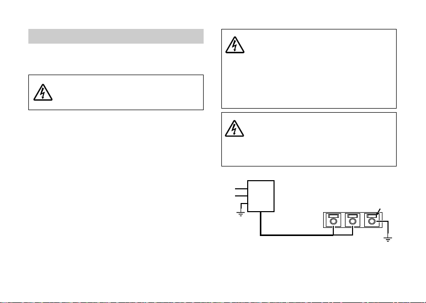
CONNEXION D’ALIMENTATION
OUTPUT
La caméra utilise un courant alternatif de 24 V
ou un courant continu de 12 V.
ATTENTION:
Prenez soin de ne pas provoquer un courtcircuit sur le cordon d’alimentation lors de
son branchement sur la caméra.
A.CONNEXION SUR LE SECTEUR
PAL: Une alimentation principale de 24 VAC
(21,6 à 26,4 VAC) 50 Hz est requise.
NTSC: Une alimentation principale de 24 VAC
(21,6 à 26,4 VAC) 60 Hz est requise.
Cette alimentation doit avoir une intensité minimum de 270 mA.
Dénudez la gaine à l’extrémité du cordon
d’alimentation sur une longueur de 10 mm.
Torsadez et redressez les fils, puis insérez-les
dans les trois orifices de la borne.
Si l’insertion ne se fait pas facilement, faites un
nouvel essai en poussant le bouton respectif audessus de l’orifice.
Fr-10
ATTENTION:
Assurez-vous que le cordon est bien branché
sur la borne en le tirant légèrement. Assurezvous aussi qu’aucun brin de fil ne ressort des
orifices de borne.
À ne brancher qu’à une alimentation 24 V CA de
classe 2.
Veillez à brancher le fil de terre en provenance de
la source 24 V CA à la borne de masse.
ATTENTION:
Si deux ou plusieurs caméras sont utilisées
avec un transformateur, prenez soin d’utiliser
un transformateur dont l’intensité nominale est
supérieure au courant consommé par le nombre
de caméras x 24 V, 270 mA.
TRANSFORMATEUR
ENTRÉE
SORTIE
PANNEAU ARRIÈRE
C.A. 24 V
Bouton
Fig.5
Page 53

B.CONNEXION SUR COURANT
CONTINU
ATTENTION:
Le boîtier d'alimentation utilisé doit répondre aux
normes en vigueur.
ATTENTION:
Si le cordon d'alimentation est courtcircuité, il passe un courant excessif, ce qui
est extrêmement dangereux. L'installation
d'un fusible est requise (voir Fig.6).
La tension d'alimentation nominale de cette caméra
est de +12 VCC (
dans cettte plage de tension. Les connexions
d'alimentation sont illustrées sur la Fig.6.
Si un fusible est requis, utilisez un fusible lent, raccordé
sur la borne + de l'alimentation et placez-le à 10cm (4
pouces) de la borne.
±10%), Prenez soin d'utiliser la caméra
ATTENTION:
÷ Prenez soin de respecter les polarités
de la fiche d'alimentation.
÷ Une consommation de 390mA est
Lors de la sélection et du branchement du cordon
d'alimentation, tenez compte des points suivants:
11
1 Courant admissible du cordon d'alimentation.
11
22
2 Chute de tension de l'alimentation par suite de
22
ALIMENTATION CC
requise par caméra.
la longueur ou de la taille excessive du fil.
FUSIBLE (lent)
1,0 A
+12 V
MASSE
10cm (4 pouces) max.
PANNEAU ARRIÈRE
CC 12 V
Button
Fig. 6
Fr-11
Page 54

SORTIE VIDEO
#1:
#2:
#3:
#4:
AGC
ESC
BLC
ECLP
#5:
#6:
#7:
#8:
AWB
SYNC
D/N
FL
SORTIE BNC
La sortie de ce connecteur est un signal vidéo
composite. Utilisez un câble coaxial 75 ohms de
haute qualité entre la caméra et l’appareil vidéo
à l’extrémité “Equipement vidéo” du câble
coaxial; terminez le signal par une résistance de
75 ohms.
Fr-12
COMMUTATEUR DIP
#1: AGC OFF/ON #5: AWB
#2: ESC OFF/ON #6: SYNC AUTO/INT
#3: BLC OFF/ON #7:
#4: ECLIPSER OFF/ON #8:
D/N AUTO/HOLD
FLICKERLESS
Remarque: 7 est le réglage en usine.
Fig. 7
HOLD/AUTO
ON/OFF
Page 55

FONCTION AGC
Cette fonction permet de maintenir le niveau
du signal vidéo de sortie en adaptant
automatiquement le réglage de l’amplificateur.
La fonction AGC peut être activée ou désactivée
en basculant le commutateur #1 sur
commutateur DIP à droite ou à gauche (par
défaut, la fonction est activée).
FONCTION DE CONTRÔLE ÉLEC-
TRONIQUE DE LA SENSIBILITÉ (ESC)
Cette fonction modifie la sensibilité de la caméra
en faisant varier la vitesse de l’obturateur
électronique en fonction des rayons incidents.
Plage ESC; 1 : 300
La fonction ESC peut être activée ou désactivée
en basculant le commutateur #2 sur
commutateur DIP à droite ou à gauche (par
défaut, la fonction est activée).
ATTENTION:
Régler le commutateur FL (commutateur DIP # 8)
sur “OFF“, sinon la fonction ESC serait inopérante.
FONCTION DE CORRECTION DE
CONTRE-JOUR (BLC)
La fonction de correction de contre-jour permet
une compensation précise pour éviter qu’un
sujet ne soit trop foncé en raison d’un fort
éclairage par l’arrière.
La fonction BLC peut être activée ou désactivée
en basculant le commutateur #3 sur
commutateur DIP à droite ou à gauche (par
défaut, la fonction est désactivée).
ATTENTION:
La fonction de correction de contre-jour (BLC) n’est
active que lorsque l’interrupteur #1 du commutateur
DIP est en position “ON” (AGC).
Fr-13
Page 56

FONCTION OCCULTATION
Lorsque vous utilisez une caméra CCD équipée
d’un objectif à diaphragme automatique dans
un endroit sombre à fond clair, le contraste
obtenu est insuffisant car le signal du fond
provoque la fermeture du diaphragme
automatique et donne ainsi lieu à des images
peu nettes. La fonction OCCULTATION, utilisée
en combinaison avec un objectif à diaphragme
automatique, permet de convertir le signal de
l’arrière-plan clair en un signal vidéo de niveau
de gris. Ce signal commande alors l’objectif à
diaphragme automatique, et ce dernier s’ouvre
de manière à obtenir un contraste suffisant.
La fonction OCCULTATION peut être activée ou
désactivée en basculant le commutateur #4 sur
commutateur DIP à droite ou à gauche (par
défaut, la fonction est désactivée).
ATTENTION:
Il faut utiliser la fonction OCCULTATION avec un
objectif à diaphragme automatique.
Lorsque l’objectif à diaphragme automatique que
vous voulez utiliser est équipé d’un sélecteur de
réponse (MOYENNE/CRÊTE), placez-le toujours sur
MOYENNE (AVERAGE).
Fr-14
RÉGLAGE DE L’OCCULTRATION
(VR802, VR803, VR804)
1. La fonction d’OCCULTATION a été réglée en
usine à une valeur standard qui permet
d’obtenir des résultats optimaux sans
nouveau réglage. Si vous voulez toutefois
effectuer un réglage fin du niveau de SEUIL
de l’OCCULTATION, procédez comme suit :
* Reportez-vous à COMMANDES EXTERNES
ET CONNEXIONS.
2. Positionnez le commutateur DIP comme suit
:
AGC : OFF
ESC : OFF
BLC : OFF
3. Réglage des RV (résistances variables) et du
commutateur :
(1) RV SEUIL (THRESHOLD) : à fond à gauche
(2) RV OCCULTATION (ECLIPSE) : au centre
(3) RV GRIS (GRAY) : au centre
(4)
Commutateur OCCULTATION (ECLIPSER) : OFF
Page 57

4. Placez le sélecteur de réponse de l’objectif à
diaphragme automatique (type vidéo) sur
MOYENNE (AVERAGE).
Visualisez une é chelle des gris
(logarithmique) ou un objet, réglez la sortie
vidéo de la caméra à 0,75 Vcc (100 IRE) en
réglant la résistance variable LEVEL de
l’objectif à diaphragme automatique.
5. Mettez le commutateur ECLIPSER (S804 #4)
sur ON.
En visualisant l’objet lumineux, réglez la
résistance variable THRESHOLD (VR802) en
la tournant vers la droit de manière à relever
le niveau du signal de sortie vidéo de la
caméra à environ 0,8 - 0,85 Vcc (voir figure 8).
6. Réglez le niveau de gris illustré dans la figure 8 à 0,35 Vcc en tournant la résistance
variable GRAY (VR804) à gauche ou à droite.
7. Visualisez un objet sur fond clair, réglez la
résistance variable ECLIPSE (VR803) en la
tournant à droite ou à gauche jusqu’à pouvoir
observer l’objet avec une bonne luminosité
et sur fond gris (voir figure 9).
Niveau de gris
0.8 ~ 0.85 Vp-p
0.35 Vp-p
Signal vidéo
V
Fig. 8
Fond gris
Image sur le moniteur
Fig. 9
Fr-15
Page 58

BALANCE AUTOMATIQUE
D’EQUI-
LIBRAGE DES BLANCS (AWB)
Le réglage de la balance des blancs commutateur
DIP # 5 est effectué par les positions AUTO,
commutateur DIP # 5 sur Righ et HOLD,
Commutateur DIP # 5 sur Left. Si le sélecteur de
balance des blancs est placé sur Right, AUTO
(automatique), le réglage de la balance des blancs
se fait automatiquement. Si la balance des blancs
n’est pas suffisante, elle peut être corrigée
manuellement en plaçant le commutateur en position Left, HOLD (maintien).Si vous n’obtenez pas
une balance optimale des blancs avec le réglage
AUTO, utilisez la fonction HOLD.
(Par réglage d’usine, le commutateur DIP est placé
sur AWB AUTO.)
ATTENTION:
Cette fonction ne sert que pour le modèle couleur
seulement.
MODE DE SYNCHRONISATION (SYNC)
MODE SYNCHRONISATION COUPLÉE AU
SECTEUR (Line lock)
(La caméra utilise une alimentation de 24 V CA.)
Ce mode de réglage permet à la caméra d'utiliser
la phase du courant alternatif comme référence.
Fr-16
Si l'on souhaite regrouper plusieurs caméras
dans un système vidéo (par exemple un circuit
vidéo, un commutateur inverseur), une
synchronisation peut être nécessaire afin
d’empêcher la reprise en boucle des images au
niveau du commutateur.
Cela peut être assuré par la commande de
verrouillage en ligne (Voir la section "L.L.
AJUSTER".)
MODE INTERNE
(Caméra utilisant une alimentation de 12 V CC)
Dans ce mode, un oscillateur à cristal interne
est utilisé comme générateur synchro INT.
Le mode de synchronisation peut être activé ou
désactivé à l’aide du commutateur DIP # 6.
Côté Left: Mode automatique
(CC : Interne, CA : Verrouillage en ligne)
Côté Right : Mode interne
(Par réglage d’usine, le commutateur DIP est
placé sur SYNC AUTO.)
Page 59

MODE JOUR/NUIT (D/N)
Cette caméra comporte deux modes de
fonctionnement AUTO et HOLD pour le mode
Jour/Nuit.
Le ré glage Jour/Nuit s'effectue
automatiquement suivant la luminosité du
sujet au mode AUTO.
Si l'on préfère maintenir les conditions
courantes, on pourra utiliser le mode HOLD.
Au cran n° 7 du commutateur DIP
Côté gauche: AUTO
Côté droit: HOLD
(Le réglage d'usine est le mode AUTO)
PRECAUTION :
En utilisant cette caméra à la lumière infrarouge
ou sous un éclairement dont la température de
couleur est de 3000 K ou moins, cette caméra
se règle automatiquement au mode nuit.
Dans des conditions défavorables (intensité ou
angle d'éclairement), il peut se produire une
fluctuation.
Le modèle CG-311 possède un circuit spécial
pour éviter de tels problèmes de fluctuation.
Si la caméra détecte des conditions de fluctuation, le mode nuit sera maintenu pendant 30
minutes.
Toutes les 30 minutes, la caméra vérifie
automatiquement si les conditions ayant causé
la fluctuation existent encore, et si c'est le cas,
elle maintient ce réglage pendant 30 minutes
de plus.
Pour éviter cet état de choses, il suffit de régler
l'intensité ou l'angle d'illumination.
SANS SCINTILLEMENT (FL)
PRECAUTION :
Cette fonction sert sous lumière fluorescente du
secteur d'alimentation avec une fréquence
différente de la fréquence de balayage de caméra.
Régler le commutateur FL, commutateur DIP #
8, sur "OFF" (désactivé) ; dans le cas contraire,
un scintillement pourrait se produire. (Par
réglage d’usine, le commutateur DIP FL est placé
sur OFF (désactivé).)
Fr-17
Page 60

REGLEUR DE NIVEAU (VR801)
Ce régleur permet d’équilibrer le niveau du signal vidéo de sortie en cas d’utilisation d’un
objectif AI (Auto-Iris) commandé en courant
continu.
REGLEUR L.L.
(MODE DE VERROUILLAGE DE LIGNE)
La phase de synchronisation de l’alimentation
de chaque caméra est réglée en usine et ne
nécessit généralement pas de correction.
LL
En pousant le bouton réglable LL (S802, S803),
la phase de synchronisation de l’alimentation
change. Les dimensions à partir du point de
croisement zéro de l’alimentation onduleuse
jusqu’au point de désactivation de Vsync du
champ impaire est de 0° au pré-réglage.
CROISEMENT AU
POINT NUL
Fr-18
S803
UP
AVANCE
DOWN
RETARD
2
S802
Fig. 10
RETARD}]AVANCE
Page 61

DONNÉES TECHNIQUES
RUBRIQUE CG-311N CG-311P
Système de télévision NTSC PAL
Alimentation électrique C.A.24V (±10%),60Hz (NTSC),50Hz (PAL) / C.C.12 V (±10%)
Consommation électrique 270mA (24VAC)/390mA (12VDC)
Eléments d’image (actif)
Sortie vidéo
Synchronisation Sync. verrouillage de ligne (c.a. 24V) / Sync. interne (c.c. 12V)
Définition horizontale 480 TV lignes 470 TV lignes
Rapport signal-bruit 48 dB (AGC hors service, pondération en service)
Eclairage minimun
de scène
11
1 Objectif à contrôle de signal vidéo
Objectif à auto diaphragme utilisable
11
22
2 Objectif à contrôle de tension CC
22
Env. 380K pixels Env. 440K pixels
1,0 Vc-c, Complet (VBS), 75 ohms / Connecteur BNC
Color mode : 1,0Lux (F1,2) / B/W mode : 0,1Lux (F1,2)
Fr-19
Page 62

RUBRIQUE CG-311N CG-311P
Connecteurs
Commandes
Panneau arrière
Panneau arrière
11
1 Le signal vidéo de sortie
11
22
2 Sortie objectif AI
22
Réglage
Interrupteurs
11
1 Phase ( Phase verticale) (Bouton-poussoir; UP et DOWN)
11
22
2 Niveau (objectif commande DC) (RT)
22
33
3 Niveau de SEUIL (RT)
33
44
4 Niveau d‘OCCULATION (RT)
44
55
5 Niveau de GRIS (RT)
55
11
1 Commutateur DIL (Dual-In-Line)
11
33
3
Borne tripolaire (verrouillage par ressort- pression)
33
1) AGC OFF/ON 5) AWB HOLD/AUTO
Température ambiante (à
laquelle les performances
sont garanties)
Dimensions
(sans objectif et connecteur)
1
2) ESC *
2
3) BLC *
4)
OCCULTATION
De -10°C à 50°C
53(W) x 55(H) x 56(D) mm
OFF/ON 6) SYNC AUTO/INT
OFF/ON 7) D/N AUTO/HOLD
OFF/ON 8) FL ON/OFF
(de 0°C à 40°C)
Poids (sans objectif) 0,2 kg
Accessoires (fournis) Fiche à 4 broches (petite) ..... 1 pièce Mode d’emploi ............ 1 volume
CLÉ À SIX PANS ................... 1 pièce
MOUNT DE CAMERA .........
*1 : ESC = Contrôle de électronique de la sensibilité Spécifications sujettes à changements sans préavis.
*2 : BLC = Correction de contre-jour
Fr-20
1 pièce
Page 63

ADVERTENCIA– PARA EVITAR EL PELIGRO
DE INCENDIOS Y DE DESCARGAS ELÉCTRICAS, NO EXPONGA ESTE APARATO A LA
LLUVIA NI A LA HUMEDAD.
PRECAUCIÓN:
¶ NO EXTRAIGA NINGUNA CUBIERTA
MIENTRAS LA CÁMARA ESTÁ EN FUNCIONAMIENTO.
¶ PAL: EMPLEE SÓLO LA TENSIÓ N DE
ALIMENTACIÓN RECOMENDADA DE
24V CA (21,6 a 26,4V CA) 50 Hz O 12VCC
(10,8 a 13,2VCC).
NTSC: EMPLEE SÓLO LA TENSIÓN DE
ALIMENTACIÓN RECOMENDADA DE
24V CA (21,6 a 26,4V CA) 60 Hz O 12VCC
(10,8 a 13,2VCC).
PRECAUCIÓN:
¶ LA MONTURA DE OBJETIVO DE LA CÁMARA
ES LA MONTURA “CS”.
¶ LA MONTURA DE OBJETIVO DE LA CÁMARA
ES POCO PROFUNDA, Y ALGUNOS OBJETIVOS PUEDEN TOCAR EL FONDO Y DAÑAR
EL FORMADOR DE IMÁGENES DE CCD.
¶ NO TOQUE LA SUPERFICIE DEL VIDRIO DE
CCD.
¶ LA CÁMARA DEBE INSTALARSE CERCA DE
UNA TOMA DE CORRIENTE QUE TENGA UN
FÁCIL ACCESO.
PRECAUCIÓN
PELIGRO DE DESCARGAS
ELÉCTRICAS NO ABRIR
PRECAUCIÓN:
PARA REDUCIR EL PELIGRO DE DESCARGAS
ELÉCTRICAS, NO ABRA LA CUBIERTA (NI LA TAPA
POSTERIOR). EN EL INTERIOR NO HAY PARTES QUE
PUEDA REPARAR EL USUARIOR.
SOLICITE EL SERVICIO TÉCNICO A PERSONAL DE
SERVICIO CUALIFICADO.
EXPLICACIÓN DE LOS SÍMBOLOS GRÁFICOS
El símbolo de un rayo con cabeza de
flecha dentro de un triángulo equilátero
tiene el propósito de avisar al usuario de
la presencia de “tensión peligrosa” sin
aislar dentro de la caja del producto que
puede ser lo suficientemente fuerte como
para constituir un peligro de descargas
eléctricas para los seres humanos.
El símbolo de cierre de exclamación
dentro de un triángulo equilátero tiene
el propósito de avisar al usuario sobre la
presencia de importantes instrucciones
de mantenimiento (servicio) de
operación en el texto que acompaña al
aparato.
Español
Sp-1
Page 64

ASPECTOS IMPORTANTES DE SEGURIDAD
1. Lea las instrucciones–Todas las instrucciones
de seguridad y de operación deberán leerse
antes de operar la cámara.
2. Guarde las instrucciones–Las instrucciones
de seguridad y de operación deberán
guardarse para poderlas consultar en el futuro.
3. Advertencia–Todas las advertencias de la
cámara y de las instrucciones de operación
deberán respetarse.
4. Siga las instrucciones–Deberán seguirse
todas las instrucciones de operación y de
utilización.
5. Limpieza–Desenchufe el cable de alimentación del aparato de la toma de corriente
antes de la limpieza. No emplee rociadores
líquidos ni limpiadores de aerosol.
Emplee un paño humedecido para la
limpieza.
6. Accesorios–No emplee accesorios que no
estén recomendados por el distribuidor de
su aparato, porque podría ocasionar peligros.
Sp-2
7. Agua y humedad–No emplee la cámara en
lugares en los que pueda quedar expuesta
al agua o a la humedad.
8. Accesorios–No ponga la cámara sobre un
carrillo, soporte, trípode, ménsula, o mesa
inestables. La cámara podría caerse, causando serios daños a algún niño o adulto, y
serios daños en la cámara. Emplee sólo los
accesorios de montaje recomendados por el
distribuidor de su aparato o que se vendan
con la cámara. Cualquier montaje de la
cámara deberá seguir las instrucciones del
distribuidor de su aparato.
8A. Las combinaciones de un
carrillo y el aparato debe-
PORTABLE CART WARNING
(Symbol provided by RETAC)
rán moverse con cuidado.
Las paradas súbitas, la
fuerza excesiva, y las superficies desniveladas
pueden causar que se
vuelque la combinación
de aparato y carrillo.
S3125A
Page 65

9. Ventilación–La cámara nunca deberá
ponerse cerca ni encima de un radiador ni
dispositivo térmico. La cámara no deberá
ponerse en una instalación empotrada como
por ejemplo en una estantería para libros o
en un bastidor a menos que se proporcione
ventilación adecuada o se respeten las
instrucciones del distribuidor de su aparato.
10.Fuentes de alimentación–La cámara deberá
operarse sólo con la fuente de alimentación
indicada en la placa de características. Si no
está seguro del tipo de alimentación del lugar
de instalación, pregúnteselo a su distribuidor
del aparato o a la compañía de electricidad
local. Para las cámaras preparadas para
operar con batería u con otras fuentes,
consulte las instrucciones de operación.
11.Protección del cable de alimentación–Los
cables de alimentación deben tenderse de
modo que no puedan ser pisados ni pellizcados con objetos que puedan ponerse
encima, prestando especial atención a los
cables en la parte de las clavijas, en la
conveniencia de las tomas de corriente, y al
punto por donde salen de la cámara.
12.Tormentas–Para mayor protección de la
cámara durante una tormenta con rayos, o
cuando se deje sólo y sin utilizar durante
períodos prolongados de tiempo,
desenchúfela de la toma de corriente y
desenchufe el cable. De este modo evitará
daños en la cámara debidos a los rayos y
sobretensiones de la línea.
13.Sobrecarga–No sobrecargue la toma de
corriente ni el cable de extensión, porque
correría el riesgo de incendios o de descargas
eléctricas.
14.Entrada de objetos y de líquidos–No introduzca nunca ningún tipo de objeto en la
cámara a través de las aberturas, porque
podría tocar puntos de tensión peligrosa o
cortocircuitar partes que podrían producir un
incendio o descargas eléctricas. No derrame
nunca ningún tipo de líquido sobre la cámara.
15.Servicio–No intente realizar el servicio de la
cámara usted mismo porque si abre las
cubiertas podría quedar expuesto a tensiones
peligrosas u otros peligros.
Solicite todo el servicio a personal de servicio
técnico cualificado.
Sp-3
Page 66

16.Daños que requieren el servicio técnico–
Desenchufe el cable de alimentación de la
toma de corriente.
Solicite el servicio a personal de servicio
técnico cualificado bajo las condiciones
siguientes.
a. Cuando se ha dañado el cable de alimen-
tación o su clavija.
b. Si se ha derramado líquido, o han caído
objetos en la cámara.
c. So se ha expuesto la cámara a la lluvia o
al agua.
d. Si la cámara no funciona con normalidad
siguiendo las instrucciones. Ajuste sólo
los controles que se abarcan en el manual
de instrucciones, porque un ajuste
inadecuado de otros controles puede
ocasionar daños y requeriría frecuentemente mucho trabajo del técnico de
servicio para arreglar la cámara y dejarla
para que funcione otra vez con normalidad.
e. Si se ha caído la cámara o se ha dañado
el exterior.
f. Cuando la cámara muestra un cambio
apreciable en el rendimiento. Esto indica
necesidad de servicio técnico.
Sp-4
17.Piezas de reemplazo–Cuando se requieran
partes de reemplazo, asegúrese de que el
técnico de servicio emplea las partes de
reemplazo especificadas por el distribuidor
cualificado o que tengan las mismas
características que las partes originales.
Las sustituciones no autorizadas pueden
producir incendios, descargas eléctricas u
otros peligros.
18.Comprobación de seguridad–Al terminar
cualquier trabajo de servicio o de reparación
en la cámara, solicite al técnico de servicio
que realice las comprobaciones de seguridad
para determinar que la cámara está en
correcto estado de funcionamiento.
Page 67

INTRODUCCIÓN
Muchas gracias por la adquisición de esta cámara
de color. Lea todo este manual de instalación y de
instrucciones antes de la utilización para poder
operar la cámara correctamente.
Esta cámara de color tiene funciones que emplean
un sensor de imagen de alta densidad y asegura
una imagen clara y nítida incluso en escenas con
partes oscuras y claras gracias a la mejora del
margen dinámico.
Puede utilizarse en una amplia gama de sistemas
de CCTV porque está provista de diversas funciones,
tales como la función de amplio margen dinámico,
de ajuste automático de la sensibilidad, equilibrio
automático del blanco en tiempo real, y salida del
objetivo de iris automático.
Incorpora las siguientes destacadas características:
1. Esta cámara proporciona una imagen clara
incluso en escenas oscuras y claras
incrementando el margen dinámico de la señal
de la imagen en comparación con las cámaras
convencionales.
2. Incluso con fuerte contraluz, puede obtener una
buena imagen sin partes demasiado blancas u
oscuras aplicando una tecnología que compone
la imagen oscura y la imagen clara.
3. El tamaño compacto ha sido posible gracias a
nuestras tecnologías de montaje y de diseño de
alta densidad.
4. 380/440 mil píxeles y CCD de 1/3 de pulgada con
producción de imágenes de alta resolución.
PRECAUCIONES PARA LA OPERACIÓN
* No toque la superficie fotoconductora del elemento
de formación de imágenes del CCD. Podrían
producirse rayadas. Si se adhiere polvo en la
superficie, frótelo con cuidado con un papel de
limpieza de objetivos.
* No emplee esta cámara en exteriores.
Evite los lugares donde existan gases inflamables o
una atmósfera corrosiva.
* Si se ensucia la caja de la cámara, frótela con un paño
seco y suave. Para la suciedad persistente de la caja,
frótela con un paño suave humedecido en una solución
de detergente neutro y agua y frótela de nuevo con
un paño seco. No emplee nunca alcohol, bencina, ni
otras soluciones volátiles.
* No tenga como imágenes fuentes con luz excesiva (luz
solar, etc.) durante muchas horas seguidas.
Si el elemento de formación de imágenes del CCD se
expone a los rayos ultravioletas durante muchas horas,
el color del filtro de la superficie del elemento de
formación de imágenes del CCD perderá persistencia.
No tenga como imágenes directamente la luz del sol
ni de iluminación, cuando se deja sola la cámara.
No tenga como imágenes directamente la luz del sol
ni de iluminación, aunque la alimentación esté
desconectada.
* Es posible que aparezcan partes blancas en la pantalla.
Sin embargo, no se trata de ninguna avería.
Con el objetivo estándar, el enfoque puede cambiar
en condiciones de iluminación infrarroja.
Para evitarlo, le recomendamos emplear objetivos
especiales sin cambios del enfoque.
Sp-5
Page 68

CONTROLES EXTERNOS Y CONEXIONES
VISTA POSTERIOR
1
2
VIDEO
L E N S
L E V E L
3
6
7
O F F
AGC
ESC
BLC
ECLP
DC12V
24VAC
O N
UP
AWB
SYNC
D/N
FL
THRE ECLP GRAY
-0
4
LL
DOWN
5
=
VISTA LATERAL
~
9
8
Sp-6
Fig. 1
11
1 Conector del objetivo (pequeño, 4 patillas)
11
22
2 Conector de salida de vídeo (BNC)
22
33
3 Regulador de nivel
33
44
4 Interruptor L. L. ; UP
44
55
5 Interruptor L. L. ; DOWN
55
66
6 Interruptor DIP
66
77
7 Terminal de entrada de alimentación
77
88
8 Tornillo de bloqueo del enfoque interior
88
99
9 Montura del objetivo
99
00
0 Control del nivel THRESHOLD
00
--
- Control del ajuste ECLIPSE
-==
= Control del ajuste GRAY
==
~~
~ Montura de la cámara (orificio cónico de 1/
~~
4”-20)
MONTURA DE LA CÁMARA
Puede montarse encima o debajo de la cámara.
PRECAUTIÓN:
Una instalción inadecuada puede provocar la caída
de la cámara deteriorándose. Consulte a personal
técnico cualificado sobre las instrucciones.
Para minimizar el ríesgo de sacudidus eléctricas u
otro tipo de lesiones, tienda cables alli donde no
se deterioren ni puedan ser tocados fortuitamente
por personas.
Page 69

OBJETIVO
21
43
La cámara puede acomodar una amplia gama
de objetivos, entre los que se incluyen el objetivo
de iris manual (vea ESC FUNCTION), el objetivo
de iris controlado por CC, y el objetivo de iris
controlado por vídeo “Estándar”.
A. CONEXIONES ELÉCTRICAS
La tabla 1 muestra dos esquemas distintos de
conexión para el conector de iris automático de
4 patillas.
Si emplea un iris automático “Estándar”,
consulte “(1) CONTROL DE SEÑAL DE VÍDEO”.
(Tabla 1)
Si emplea un iris controlado por CC, emplee la
“(2) IMPULSIÓN POR TENSIÓN DE CC”.
PRECAUCIÓN:
La alimentación de salida para el objetivo de iris
automático es de +9V CC y la capacidad máxima de
corriente es de 40 mA. Cuando emplee un objetivo de iris
automático que requiere una tensión y corriente distintas
a las especificadas, suministre la alimentación del objetivo
sólo desde una fuente de alimentación externa.
Ajuste el interruptor ESC (interruptor #2 de los
interruptores DIP) a “OFF“ cuando utilice un tipo de
objetivo con diafragma automático.
Conector del objetivo Objetivo de iris automático
(Visto desde el lado de conexiones de la clavija)
Fig. 2
Tabla 1
OBJETIVO DE IRIS AUTOMÁTICO
N.° de patillas
del conector
1
2
3
4
(1) CONTROL DE
SEÑAL DE VÍDEO
+9V CC (40 mA máx.)
+9V CC (40 mA máx.)
AI-VIDEO
TIERRA
IMPULSIÓN POR
(2)
TENSIÓN DE CC
CONTROL (–)
CONTROL (+)
IMPULSIÓN (+)
IMPULSIÓN (–)
Sp-7
Page 70

B. CONEXIÓN MECÁNICA
Antes de montar cualquier objetivo en esta
cámara, compruebe que la dimensión posterior del objetivo no exceda la longitud máxima
siguiente, porque de lo contrario podría dañarse
el formador de imágenes de CCD.
“X”
CS = 0,2" (6 mm)
La cámara se entrega lista par
aceptar lentes del tipo “CS”.
Si se va a usar la lente de
montura estándar “C”, primero
debe instalarse el anillo
”Adaptador de montura C” y
después la lente.
C = 0,4" (10 mm)
OBJETIVO
“X”
Fig. 3
C. AJUSTE DE LA DISTANCIA FOCAL INTERIOR
La cámara se ha ajustado en fábrica para la
distancia focal interior adecuada para emplear un
objetivo de montura CS estándar. Sin embargo,
cuando el objetivo está montado, puede resultar
necesario reajustar la distancia focal interior para
adaptarla al objetivo utilizado.
Sp-8
PRECAUCIÓN:
Si el tornillo de bloqueo del enfoque interior se aprieta
demasiado, la sección roscada de la “Montura del
objetivo” puede dañarse.
Para el apriete del tornillo de bloqueo del enfoque
interior, emplee una LLAVE DE APRIETE de 1,5 mm.
Sostenga el lado corto del mango (como se muestra
en la Fig. 4), y gírelo hacia la derecha un poco hasta la
posición con parada.
Gírelo un poco máx. (aprox. 15 grados) desde esta
posición.
Aprox. 15°
LLAVE DE APRIETE
10 mm
50 mm
CÁMARA
Fig.4
Page 71

1. Objetivo de enfoque fijo
¶ Monte el objetivo firmemente en la
cámara.
¶ Ajuste el anillo de enfoque del objetivo a
la posición de infinito (∞).
¶ Ajuste la cámara a una distancia de 10 m
o más del objeto.
¶ Asegúrese de que el iris del objetivo está
completamente abierto.
¶ Afloje el tornillo de bloqueo del enfoque
interior en el lado de la cámara empleando una LLAVE DE APRIETE de 1,5 mm
(gírela hacia la izquierda). Para ver la
posición, consulte la figura 1.
¶ Después de comprobar que el anillo del
objetivo está en la posición de infinito (∞),
gire la montura del objetivo al punto en
el que se vea la imagen más nítida en la
pantalla del monitor y apriete el tornillo
de bloqueo del enfoque interior girándolo
hacia la derecha.
2. Objetivo zoom
¶ Con la cámara en funcionamiento, mire
un objeto que esté por lo menos a 25 m.
¶ Asegúrese de que el iris del objetivo está
completamente abierto.
¶ Ajuste el enfoque del objetivo (LENS FO-
CUS) a la posición FAR.
¶ Ajuste el ZOOM del objetivo a WIDE.
(Campo de visión de gran angular)
¶ Afloje el tornillo de bloqueo del enfoque
interior en el lado de la cámara empleando una LLAVE DE APRIETE de 1,5 mm.
Gire la montura del objetivo al punto en
el que se vea la imagen más nítida en la
pantalla del monitor.
Apriete el tornillo de bloqueo del enfoque
interior girándolo hacia la derecha. (Para
ver la posición, consulte la figura 1.)
¶ Ajuste el ZOOM del objetivo a TELE-
PHOTO. (Campo de visión más reducido)
¶ Ajuste el enfoque del objetivo (LENS FO-
CUS) (mediante el controlador) para
conseguir la mejor imagen posible.
Sp-9
Page 72

CONEXIÓN DE LA ALIMENTACIÓN
OUTPUT
La cámara emplea alimentación de 24VCA ó de
12VCC como fuente de alimentación principal.
PRECAUCIÓN:
Tenga cuidado de no cortocircuitar el cable
de la línea de alimentación cuando conecte
el cable de alimentación en la cámara.
A. CONEXIÓN DE LA ALIMENTACIÓN DE CA
PAL: Se requiere alimentación principal de 24
V CA (21,6 a 26,4 V CA), 50 Hz
NTSC: Se requiere alimentación principal de 24
V CA (21,6 a 26,4 V CA), 60 Hz
Esta fuente de alimentación deberá tener un
amperaje mínimo de 270 mA. Extraiga la funda
del extremo del cable de alimentación de unos
10 mm de longitud. Retuerza y enderece los
conductores, e insértelos en los tres orificios del
terminal. Si la inserción no puede realizarse con
facilidad, inténtelo de nuevo mientras presiona
el botón respectivo de encima del orificio.
Sp-10
PRECAUCIÓN:
Confirme que el cable de alimentación esté
conectado al terminal con seguridad tirando del
cable.
Confirme que no sobresalgan conductores por fuera de
los orificios del terminal.Conectar la fuente de
alimentación sólo a 24 VAC clase 2.
Si suministra la alimentación una fuente de corriente
de 24 VAC, cerciorarse de conectar la toma de tierra al
terminal de masa (GND).
PRECAUCIÓN:
Cuando se empleen dos o más cámaras con
un transformador, emplee un trans-
formador que tenga una capacidad de más que la
que se consume con el número de cámaras x 24V
CA 270 mA.
TRANSFORMADOR
ENTRADA
SALIDA
PANEL POSTERIOR
Botón
24V CA
Fig.5
Page 73

B. CONEXIÓN DE LA ALIMENTACIÓN DE CC
ATENCIÓN:
el equipo de alimentación empleado debe cumplir
las normas vigentes.
PRECAUCIÓN:
Si el cable de la alimentación se
cortocircuita, circulará excesiva corriente,
lo cual es muy peligroso. Se requerirá un
fusible de la línea. (Vea la Fig.6).
La tensión de alimentación nominal de esta cámara es
de +12V CC (
Asegúrese de emplear la cámara dentro de este
margen de tensión. Las conexiones de alimentación
se muestran en la Fig.6. Si se requiere un fusible,
emplee un fusible de fusión lenta conectado al terminal
+ de la alimentación dentro de 10cm del terminal.
±10%).
PRECAUCIÓN:
÷ Asegúrese de conectar correctamente
las polaridades de la clavija de la
alimentación.
÷ Es necesario un consumo de corriente
Cuando seleccione y conecte el cable de
alimentación, tenga presente lo siguiente:
11
1 La corriente permisible del cable de
11
22
2 La caída de tensión de alimentación debida
22
ALIMENTACIÓN DE CC
+12 V
TIERRA
de 390mA por cámara.
alimentación.
a la longitud excesiva o al tamaño del cable.
FUSIBLE (fusión
lenta) de 1,0 A
10cm MÁX.
PANEL POSTERIOR
Botón
12 VCC
Fig. 6
Sp-11
Page 74

SALIDA DE VÍDEO
#1:
#2:
#3:
#4:
AGC
ESC
BLC
ECLP
#5:
#6:
#7:
#8:
AWB
SYNC
D/N
FL
SALIDA BNC
La salida de este conector es una señal de vídeo
compuesta. Emplee un cable coaxial de 75Ω
de alta calidad entre la cámara y el otro equipo
de vídeo en el lado del “Equipo de vídeo” del
cable coaxial, y termine la señal con un resistor
de 75Ω.
Sp-12
INTERRUPTOR DIP
#1: AGC OFF/ON #5: AWB HOLD/AUTO
#2: ESC OFF/ON #6: SYNC AUTO/INT
#3: BLC OFF/ON #7: D/N AUTO/HOLD
#4:
ECLIPSER
OFF/ON #8:
FLICKERLESS
NOTA: 7 es el ajuste de fábrica.
Fig. 7
ON/OFF
Page 75

FUNCIÓN DE AGC
Esta función mantiene el nivel de salida vídeo
de la cámara variando automáticamente el control de ganancia.
El interruptor de la función AGC puede conectarse / desconectarse (ON/OFF) girando #1 del
interruptor DIP a la derecha e izquierda.
(El ajuste de fábrica es AGC ON.)
FUNCIÓN DE CONTROL ELECTRÓ-
NICO DE LA SENSIBILIDAD (ESC)
Esta función cambia la sensibilidad de la cámara
variando la velocidad del obturador electrónico
de acuerdo con la cantidad de luz incidente.
Margen de ESC; 1 : 300
El interruptor de la función ESC puede conectarse / desconectarse (ON/OFF) girando #2 del
interruptor DIP a la derecha e izquierda.
(El ajuste de fábrica es ESC ON).
PRECAUCIÓN:
Ajuste el interruptor FL (interruptor DIP #8) a “OFF“
de lo contrario la función ESC no funcionará.
FUNCIÓN DE COMPENSACIÓN DE
CONTRALUZ (BLC)
La función de compensación de contraluz
permite la corrección precisa de la imagen para
evitar que el motivo se vea demasiado oscuro
debido a contraluz.
El interruptor de la función BLC puede conectarse / desconectarse (ON/OFF) girando #3 del
interruptor DIP a la derecha e izquierda.
(El ajuste de fábrica es BLC OFF)
PRECAUCIÓN:
La función de compensación de contraluz (BLC)
sólo es eficaz si el interruptor Dip-switch #1 del
interruptor DIP se encuentra en la posición
“ON” (AGC).
Sp-13
Page 76

FUNCIÓNAMIENTO DEL ECLIPSADOR
Si se usa una cámara CCD equipada con una
lente automática en una zona oscura con fondo
de luz, no se consigue un suficiente contraste,
ya que la señal de fondo provoca el cierre de la
lente automática, dando como resultado
imágenes borrosas. Sin embargo, si se ha
conectado la función de ECLIPSER junto con la
lente automática, la señal de fondo luminoso
se corta y se convierte en una señal vídeo de
nivel gris. Con esta señal se activa la lente
automática de tal modo que la lente se abre y
puede obtenerse suficiente contraste.
El interruptor de la función ECLIPSER puede
conectarse/desconectarse (ON/OFF) girando #4
del interruptor DIP a la derecha e izquierda. (El
ajuste de fábrica es OFF)
PRECAUCIÓN:
La función ECLIPSER debe usarse con la lente
automática.
Si la lente automática a ser usada va equipada con
un selector de respuesta (AVERAGE/PEAK), ajustarlo
siempre a AVERAGE.
Sp-14
CONTROL DE AJUSTE
(VR802,VR803, VR804)
1. El ECLIPSADOR sale ajustado de fábrica con
un ajuste estándar y los mejores resultados
se obtienen sin reajustarlo. No obstante,
para un ajuste de precisión del nivel
THRESHOLD proceder de la manera
siguiente.
Referido a CONTROLES EXTERNOS Y
*
CONEXIONES
2. Ajustar la posición del DIP-SW
AGC : OFF
ESC : OFF
BLC : OFF
3. Ajuste de VR (resistores variables) y
conexión:
(1) THRESHOLD VR : en sentido contrahorario
(2) ECLIPSE VR : centro mecánico
(3) GRAY VR : centro mecánico
(4) ECLIPSER SW : OFFHOLD (ON).
Page 77

4. Ajustar el selector de respuesta de la lente
automática (tipo vídeo) a AVERAGE.
Mirando la escala gris (logarítmica) o un
objeto, ajustar el nivel de salida de vídeo de
la cámara a 0,75 Vp-p (100IRE) ajustando el
NIVEL VR de la lente automática.
5. Ajustar el ECLIPSER SW (S804 #4) a ON
(conectado).
Mirando un objeto brillante, ajustar
THRESHOLD VR (VR802) girándolo en
sentido horario de tal modo que el nivel de
salida de vídeo de la cámara se recorte a
0,8-0,85 Vp-p (ver Fig. 8).
6. Ajustar el nivel del gris mostrado en la fig.
8 a 0,35 Vp-p girando el GRAY VR (VR804)
en sentido horario o contrahorario.
7. Mirando un objeto enfrente de un fondo
claro, ajustar el ECLIPSE VR (VR803)
girándolo en sentido horario o contrahorario
hasta que pueda verse el objeto con buena
claridad y el fondo se vuelva gris (ver Fig.
9).
Nivel gris
0,8 ~ 0,85 Vp-p
0,35 Vp-p
Señal vídeo
V
Fig.8
Fondo gris
Imagen del monitor
Fig.9
Sp-15
Page 78

BALANCE AUTOMÁTICO DE
BLANCOS (AWB)
El ajuste del balance de blancos (patilla n.º 5 del
conmutador DIP) se efectúa seleccionando las
posiciones AUTO (patilla n.º 5 del conmutador
DIP en posición Right) y HOLD (patilla n.º 5 del
conmutador DIP en posición Left). Colocando
el selector en la posición AUTO (Right), el balance de blancos se ajusta automáticamente. Si
el balance de blancos no es suficiente, puede
corregirse manualmente colocando el
conmutador en la posición HOLD (Left).
Si no consigue obtener un balance de blancos
óptimo en la posición AUTO, utilice la función HOLD
(Ajustado de fábrica en la posición AWB AUTO).
PRECAUCIÓN:
Esta función es solamente para el modelo de
color.
Sp-16
MODO DE SINCRONIZACIÓN (SYNC)
MODO DE SINCRONIZACIÓN EN LÍNEA
(Cámara con alimentación de red de 24V CA)
Este modo permite a la cámara utilizar la fase
de la corriente alterna como referencia.
Si uno desea agrupar varias cámaras en un
sistema de video (por ejemplo, un circuito de
video o un conmutador inversor), puede ser
necesario sincronizarlas para evitar generar un
bucle de imágenes en el conmutador.
Esto puede conseguirse mediante el control de
sincronización en línea.
(Consulte la sección "AJUSTADOR DE L.L.").
MODO INTERNO
(Cámara con fuente de alimentación de 12V CC)
En este modo se utiliza un oscilador a cristal
interno como generador de sincronización INT.
El modo de sincronización puede activarse o
desactivarse cambiando la posición de la patilla
n.º 6 del conmutador DIP.
Posición Left: modo automático (CC: interno,
CA: sincronización en línea)
Posición Right: modo interno
(Ajustado de fábrica en la posición SYNC
AUTO).
Page 79

DÍA/NOCHE (D/N)
En el modo de Día/Noche de esta cámara,
dispondrá de dos modos, el automático
(AUTO) y el de retención (HOLD).
La operación de Día/Noche funciona
automáticamente de acuerdo con la
iluminación del motivo en el modo AUTO.
Cuando prefiera conservar el estado actual,
podrá emplear el modo HOLD.
En el interruptor N.° 7 del interruptor DIP
Lado izquierdo: AUTO
Lado derecho: HOLD
(El ajuste predeterminado es el del modo
AUTO.)
PRECAUCIÓN:
Cuando utilice esta cámara con iluminación
infrarroja o con iluminación cuya temperatura
del color sea de 3.000 K o menos, la cámara
cambiará automáticamente al modo de noche.
En situaciones desfavorables (potencia o
ángulo de la iluminación), es posible que se
produzcan conflictos entre los dos modos.
La CG-311 tiene un circuito especial para evitar
tales conflictos.
Si la cámara detecta un estado conflictivo
entre los modos, se mantiene el modo de
noche durante 30 minutos.
La cámara comprueba automáticamente cada
30 minutos si persisten las condiciones que
ocasionaron conflictos, y si el problema
persiste mantiene el modo durante otros 30
minutos.
Para evitar esta operación, deberá ajustar la
potencia o el ángulo de la iluminación.
SUPRESIÓN DEL PARPADEO (FL)
PRECAUCIÓN:
Esta función se utiliza en áreas con luces
fluorescentes en las que la frecuencia de la
alimentación de red es diferente de la frecuencia
de exploración de la cámara.
Sitúe el selector FL (patilla n.º 8 del conmutador
DIP) en la posición "OFF", en caso contrario la
imagen podría parpadear.
(La función FL viene ajustada de fábrica en la
posición OFF).
Sp-17
Page 80

REGULADOR DE NIVEL (VR801)
Este controlador sírve para regular el nivel de
salida vídeo cuando se utilice la lente Auto-iris
dirigida por tensión DC.
REGULADOR L.L.
(MODO DE BLOQUEO DE LÍNEA)
La fase sincronizadora de alimentación de cada
cámara está ajustada a la misma fase de
fábrica. Normalmente, la fase sincronizadora
LL
DOWN
S802
2
S803
UP
ARRIBA ABAJO
de alimentación no precisa reajustes.
La fase sincronizadora de alimentación se cambia apretando el interruptor L.L. ADJ (S802,
S803).
La medida del punto de conexión cero de la
forma de onda del voltaje de alimentación al
punto de desactivación de V sync del campo de
adición está preajustada a 0°.
PUNTO DE CRUCE
CERO
Sp-18
Fig. 10
ABAJO}]ARRIBA
Page 81

ESPECIFICACIONES
ÍTEM CG-311N CG-311P
Sistema de TV NTSC PAL
Alimentación 24 VCA (±10%),60Hz (NTSC), 50Hz (PAL) / 12VCC (±10%)
Consumo de alimentación 270mA (24VCA)/390mA (12VDC)
Elementos de imagen (activos) Approx. 380K pixeles Approx. 440K pixeles
Salida de vídeo
Sincronización
Definición horizontal 480 líneas de TV 470 líneas de TV
Relación de señal/ruido 48 dB (AGC OFF, ponderado)
Iluminación mínima de la escena
Objetivo de iris
automático utilizable
Sincronización de bloqueo de línea (24VCA) / Sincronización interna (12VCC)
Color mode : 1,0lux (F1,2) / B/W mode : 0,1lux (F1,2)
11
1 Objetivo de control de señal de vídeo
11
22
2 Objetivo de control de tensión de CC
22
1,0Vp-p, compuesta (VBS), 75 Ω / conector BNC
Sp-19
Page 82

ÍTEM CG-311N CG-311P
Conectores
Controles
PANEL TRASERO
PANEL TRASERO
11
1 Salida vídeo
11
22
2 Salida lente Auto-iris
22
Ajuste
Interruptor
33
3 Conexión de clema tripolar (Bloqueo de resorte a presión)
33
11
1 Fase (fase vertical) (Interruptor de pulsador; UP y DOWN)
11
22
2 Nivel (objetivo de impulsión de CC) (VR)
22
33
3 Nivel THRESHOLD (VR)
33
44
4 Ajuste ECLIPSE (VR)
44
55
5 Ajuste GRAY (VR)
55
11
1 Interruptor DIP
11
1) AGC OFF/ON 5) AWB HOLD/AUTO
1
2) ESC *
3) BLC *
OFF/ON 6) SYNC AUTO/INT
2
OFF/ON 7) D/N AUTO/HOLD
4) ECLIPSER OFF/ON 8)FL ON/OFF
Temperatura ambiente
(temperatura a la que se
garantiza el rendimiento)
Dimensiones
(menos objetivo y conector)
-10°C a 50°C
(0°C a 40°C)
53(W) x 55(H) x 56(D) mm
Peso (sin el objetivo) 0,2 kg
Accesorios (suministrados)
*1: Control electrónico de la sensibilidad Especificaciones sujetas a cambios sin previo aviso.
*2: Compensación de contraluz
Clavija de 4 patillas (tipo pequeño)
1 pieza Manual de instrucciones ..... 1 pieza
LLAVE DE APRIETE ..................... 1 pieza
MONTURA DE LA CÁMARA ...
Sp-20
1 pieza
Page 83

1116, Suenaga, Takatsu-ku, Kawasaki 213-8502, Japan
Printed in Japan/Gedruckt in Japan/Imprimé au Japon
Impreso en Japón/
1304670012
 Loading...