

Page 1

Operating Manual
FUJITSU Workstation CELSIUS
W570 / W570power / W570power+
W580 / W580power / W580power+
System
Page 2

Thank you for buying an inno
vative product from Fujitsu.
Latest information abo
on our website: "
You c a n find driver upda
Should you have any te
• our Hotline/Service
• Your sales partner
• Your sales office
We hope you enjoy using your new Fujitsu system!
ut our products, useful tips, updates etc. is available
//www.fujitsu.com/fts/"
http:
tes at: "
http://support.ts.fujitsu.com/download"
chnical questions, please contact:
Desk ("
http://support.ts.fujitsu.com/contact/serv icedesk")
Page 3

Page 4

Published by / Contact address in the EU
chnology Solutions GmbH
Fujitsu Te
Mies-van-der-Rohe-Straße 8
80807 Munich, Germany
www.fujitsu.com/fts/"
http://
"
Copyright
u Technology Solutions GmbH 2.018. All rights reserved.
©Fujits
Publication Date
07/2018
Order No.: A26361-K1446-Z320-1-7619, edition 2
Page 5

FUJITSU Workstation CELSIUS
W570 / W570power / W570power+
W580 / W580power / W580power+
Operating Manual
Your CELSIUS... 7
Ports and Operating Elements 9
Important notes 11
Getting started 13
Operation 22
Troubleshooting and tips 29
System expansions 33
Technical data 82
Index 83
Page 6

Remarks
Notes on the product description are consistent with Fujitsu´s design specifications and
are made available for comparison purposes. The actual results may differ due to several
factors. Technical data is subject to change without notification. Fu jitsu does not accept
any responsibility for technical or editorial errors nor for omissions.
Trademarks
Fujitsu, the Fujitsu logo and CELSIUS are registered trademarks of Fujitsu Limited
or its subsidiaries in the USA and other countries.
Kensington and MicroSaver are registered trademarks of ACCO Brands.
USB Type-C™ and USB-C™ are trademarks of the USB Implementers Forum
in the USA and other countries.
Microsoft and Windows are trademarks or registered trademarks of Microsoft
Corporation in the U S A and/or oth er countries.
All other trademarks mentioned here are the property of their particular owner.
Copyright
No part of this publication may be copied, reproduced or translated without
prior written permission from Fujitsu.
No part of this publication may be stored or transmitted in any electronic manner
without written permission from Fujitsu.
Page 7

Contents
Contents
Your CELSIUS... ....................................................................... 7
Notational conventions .................................................................. 8
ValidityoftheReferenceManual ......................................................... 8
Ports and Operating Elemen
Front ................................................................................... 9
Rear ................................................................................... 10
Important notes ........................................................................ 11
Safetyinformation ....................................................................... 11
Transportingthedevice .................................................................. 11
Cleaning thedevice ..................................................................... 12
Energysaving,disposaland recycling .................................................... 12
Gettingstarted ......................................................................... 13
Unpacking and chec
Steps for initial s
Setting up the dev
Connecting the de
Connecting exter
Ports on the devi
Connecting a mon
Connecting the
Connecting th
Connecting ex
Connecting ex
Switching on
Switch on the
Installing t
Operation .............................................................................. 22
Switchthedeviceon .................................................................... 22
Switching off thedevice ................................................................. 22
Procedure in an emergency . . . ....................................................... 22
Indicators onthedevice ................................................................. 23
Keyboard ............................................................................... 24
Important keys and keyboard shortcuts . . . . ............................................ 24
Settings inBIOS Setup .................................................................. 25
Property and data protection . . ........................................................... 26
Anti-theft protection and lead-sealing . . . . . . ............................................ 26
Mechanical casing lock (optional) . . ................................................... 27
BIOSsetupsecurityfunctions ........................................................ 28
Accessauthorisation via SmartCard .................................................. 28
Operating the SmartCard reader (optional) ............................................ 28
bleshooting and tips ..............................................................
Trou
ifproblemsoccur ...................................................................
Help
bleshooting .........................................................................
Trou
er-onindicatorremainsunlit after you have switched onyourdevice .................
Pow
device cannot be switched off with the On/Off switch. . .............................
The
itorremainsblank ...............................................................
Mon
mousepointerdisplayed onthescreen ............................................
No
kingthe delivery .....................................................
etup ....................................................................
ice ....................................................................
viceto the mainssupply ................................................
naldevices .............................................................
ce ..................................................................
mouse ...............................................................
e keyboard . ...........................................................
ternaldevicesto the parallel orserialinterface(optional) ..................
ternaldevicesto the USBports .........................................
for the firsttime:installingthesoftware .......................................
monitorandthemachine ...............................................
hesoftware ...............................................................
ts .........................................................
itor ................................................................
13
13
14
15
16
17
18
19
19
19
20
20
21
21
29
29
29
29
30
30
31
9
Fujitsu 3
Page 8

Contents
Time and/or date is not correct . . . . . . ................................................. 31
Errormessageson thescreen ........................................................ 31
Installing new software .................................................................. 31
Tips .................................................................................... 32
Systemexpansions .................................................................... 33
Information about boards ................................................................ 34
Opening the casing . . ................................................................... 35
Closingthecasing ...................................................................... 36
Open and close the drive cage (only for the mode l FUJITSU Workstation CELSIUS W 57 0power+
/W580power+) ......................................................................... 37
Openthe drive cage ................................................................. 38
Pullthe drive cage outofthecasing. .................................................. 39
Slidethe drive cage into thehousing. ................................................. 40
Closethe drive cage ................................................................. 41
Overview ofthe drive bays anddrivesin your device ....................................... 42
Installandremovethe slim-linedrive ..................................................... 42
Installing anaccessible drive ......................................................... 42
Removing anaccessibledrive ........................................................ 43
Installing and removing the accessible 5
Fitting the drive cover for the 5
1
/4inchdrive ...................................... 45
1
/4inchdrive ........................................... 45
Installing anaccessible drive ......................................................... 46
Removing anaccessibledrive ........................................................ 47
Overview ofthe hard disk drives ......................................................... 48
Removing and installing hard disks in the lower part of the device (variants: FUJITSU
Workstation CELSIUS W570 / W570power / W580 / W580power) . .......................... 53
Removing thehard diskdrive ........................................................ 54
Installing aharddiskdrive ........................................................... 55
Removing and installing hard disks in the lower part of the device (variant: FUJITSU Workstation
CELSIUS W570power+, cold plug) . . . . . . ................................................. 56
Removing thehard diskdrive ........................................................ 56
Installing aharddiskdrive ........................................................... 58
Removing and installing 2
CELSIUS W570 / W570power and W580 / W580power: according to the operable 5
drive, FUJITSU Workstation CELSIUS W570power+ / W580power+: on the drive frame) . . .... 59
Removing the hard disk drive (size: 2
Install a hard disk, size 2
Removing and installing 3
1
/2inch hard disks or Solid State Discs (SSD) (FUJITSU Workstation
1
1
/2inchesor aSolidState Disk (SSD) ......................... 61
1
/2inch hard disks in the drive cage (only for the model FUJITSU
/2inchesor a Solid State Disc (SSD)) ............. 60
1
/4inch
Workstation CELSIUS W570 power+ with installation kit 1 (standard)) . . . . ................... 62
Removing thehard diskdrive ........................................................ 62
Installing aharddiskdrive ........................................................... 63
Removing and installing 2
1
/2inch hard disks in the drive cage (only for the model FUJITSU
Desktop CELSIUS W570power+, with both installation kits) . . . .............................. 65
Installing the harddiskdrive .......................................................... 65
Removing ahard disk drive .......................................................... 67
Removing and fittingthe front fan ........................................................ 69
Removing thefrontfan .............................................................. 69
Installing the frontfan ................................................................ 70
Installing and removing a board . . ........................................................ 71
Installing a board .. . . ................................................................ 71
Removing a board . . . ................................................................ 73
Installing and removing an M.2 module . . ................................................. 75
Installing an M.2 module . ............................................................ 75
4 Fujitsu
Page 9

Contents
Removing anM.2 module ............................................................ 76
Installing and removing WLAN antennas . . . . . . ............................................ 77
Installing external WLAN antennas . ................................................... 77
Removing external WLAN antennas . . . . . . ............................................ 78
Installing and removing heat sinks ........................................................ 78
Removing theheatsink .............................................................. 78
Installing the heatsink ............................................................... 79
Mainboard expansions .................................................................. 80
Upgrading mainmemory ............................................................. 80
Replacing theprocessor ............................................................. 80
Replacing thelithiumbattery ......................................................... 81
Technicaldata ......................................................................... 82
Index .................................................................................. 83
Fujitsu 5
Page 10

Contents
6 Fujitsu
Page 11

Your CELSIUS...
Your CELSIUS...
Overview
... is available with various configuration levels which differ in terms of hardware and software
equipment. You can install accessible drives (e.g. DVD drives) a nd other modules.
This manual tells you how to start using your device and how to operate it in daily u se.
This manual applies for all c onfiguration levels. Depending on the chosen configuration
level, some of the hardware components d escribed may not be available on your PC .
Please also read the notes about your operating system.
Depending on the configuration selected, the operating s ystem is preinstalled
on your hard disk (e.g. Windows).
Further information on this device is also provided:
• in the "Q uick Start Guide" poster
• in the "Safety/regul
• in the "Warranty" manual
• in the BIOS manual f
• in the operating manual for the monitor
• in the manual for t
• in the documentation for your operating system
• in the informati
ations" manual
or your device
he mainboard
on files (e.g. *.PDF, *.HTML, *.DOC, *.CHM, *.TXT, *.HLP)
Fujitsu 7
Page 12

Your CELSIUS...
Notational conventions
Pay particular attention to text marked with this symbol. Failure to observe
these warnings could pose a risk to health, damage the device or lead
to loss of data. T he warranty will be invalidated if the device becomes
defective through failure to observe these warnings.
Indicates important informa
tion for the proper use of the device.
►
This font
This font
This font
"This font"
Key
This font
Indicates an activity that must be performed
Indicates a result
indicates data entered
the command line, e.g.
start a program (star
indicates information that is displayed on the screen by a program, e.g.:
Installation is complete.
indicates
• terms and texts used in a software interface, e.g.: Click on Save
• names of programs or files, e.g. Windows or setup.exe.
indicates
• cross-references to another section, e .g. "Safety information"
• cross-references to an external s ource , e.g. a web address: For more
information, go to "
• Names of CDs, DVDs and titles or designations for other materials,
e.g.: "CD/DVD Drivers & Utilities" or "Safety/Regulations" manual
indicates a key on the keyboard, e.g:
indicates terms and texts that a re emphasised or highlighted, e.g.: Do
not switch off the device
using the keyboard in a program dialogue or at
your password (Name123) or a command used to
t.exe)
http://www.fujitsu.com/fts/"
Validity of the Reference Manual
ference Manual is valid for the following systems:
This Re
•FUJITS
• FUJITSU Workstation CELSIUS W570power
•FUJIT
• FUJITSU Workstation CELSIUS W580
•FUJI
• FUJITSU Workstation CELSIUS W580power+
U Workstation CELSIUS W570
SU Workstation CELSIUS W570power+
TSU Workstation CELSIUS W580power
F10
8 Fujitsu
Page 13
Ports and Operating Elem ents
Ports and Operating Elements
Ports
This chapter presents the individual hardware components of your device. This will provide
you with an overview of the ports and operating elements on the device. Please familiarise
yourself with these components before you start to work with the device.
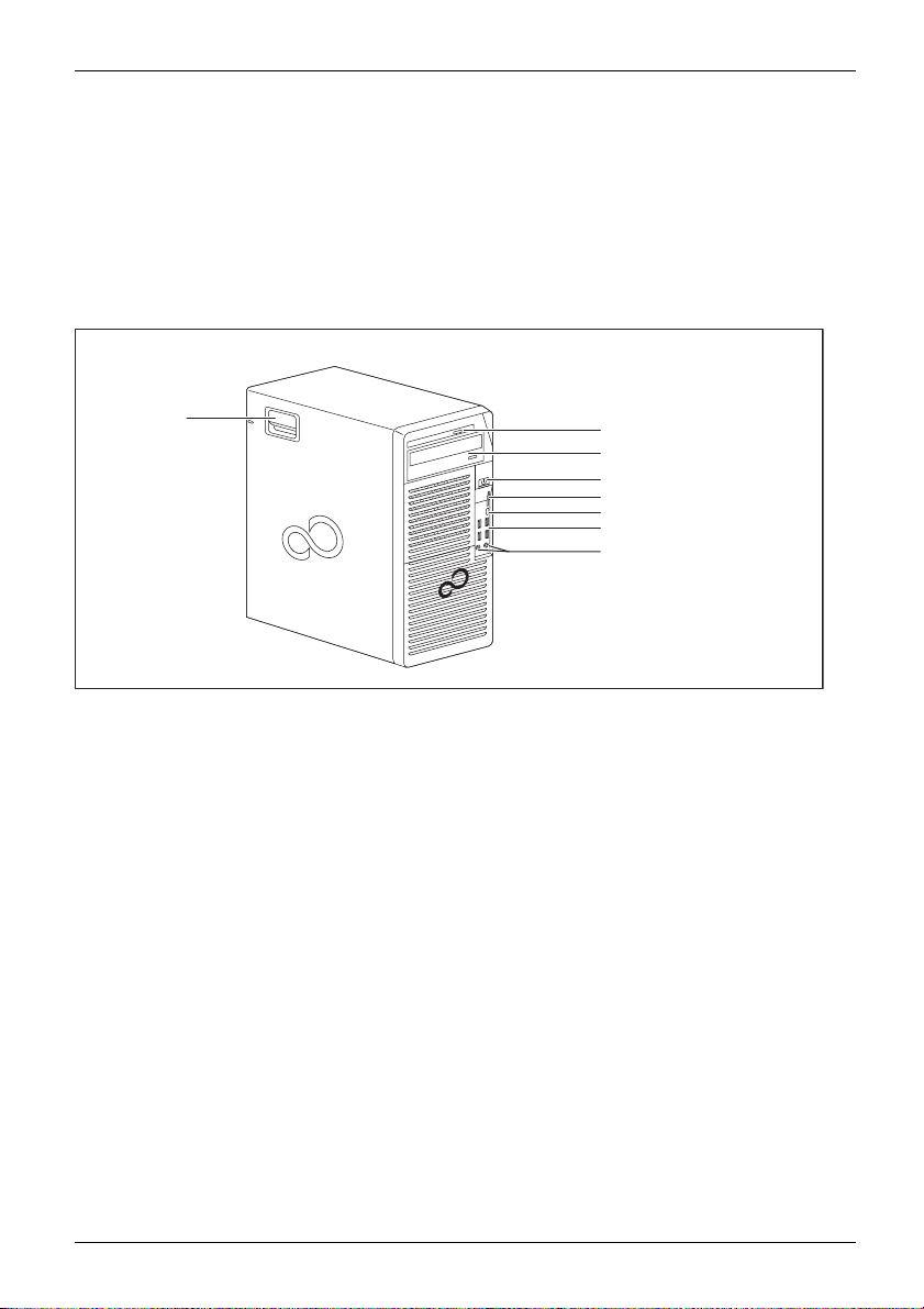
Front
8
1 = Slim-line drive
2 = Module bay for a 5
3 = ON/OFF switch
4 = Slot fo r memory cards (format: SD
Secure Digital card)
5 = USB connection 3.1 with a charging
function (USB Type-C™)
1
/4-inch drive
1
2
3
4
5
6
7
6 = USB ports
7 = Microphone connection (right), headphone
connection (left).
In order to use a headset, connect the
headset with both connections.
8 = Latch with optional casing lock
Fujitsu 9
Page 14
Ports and Operating Elements
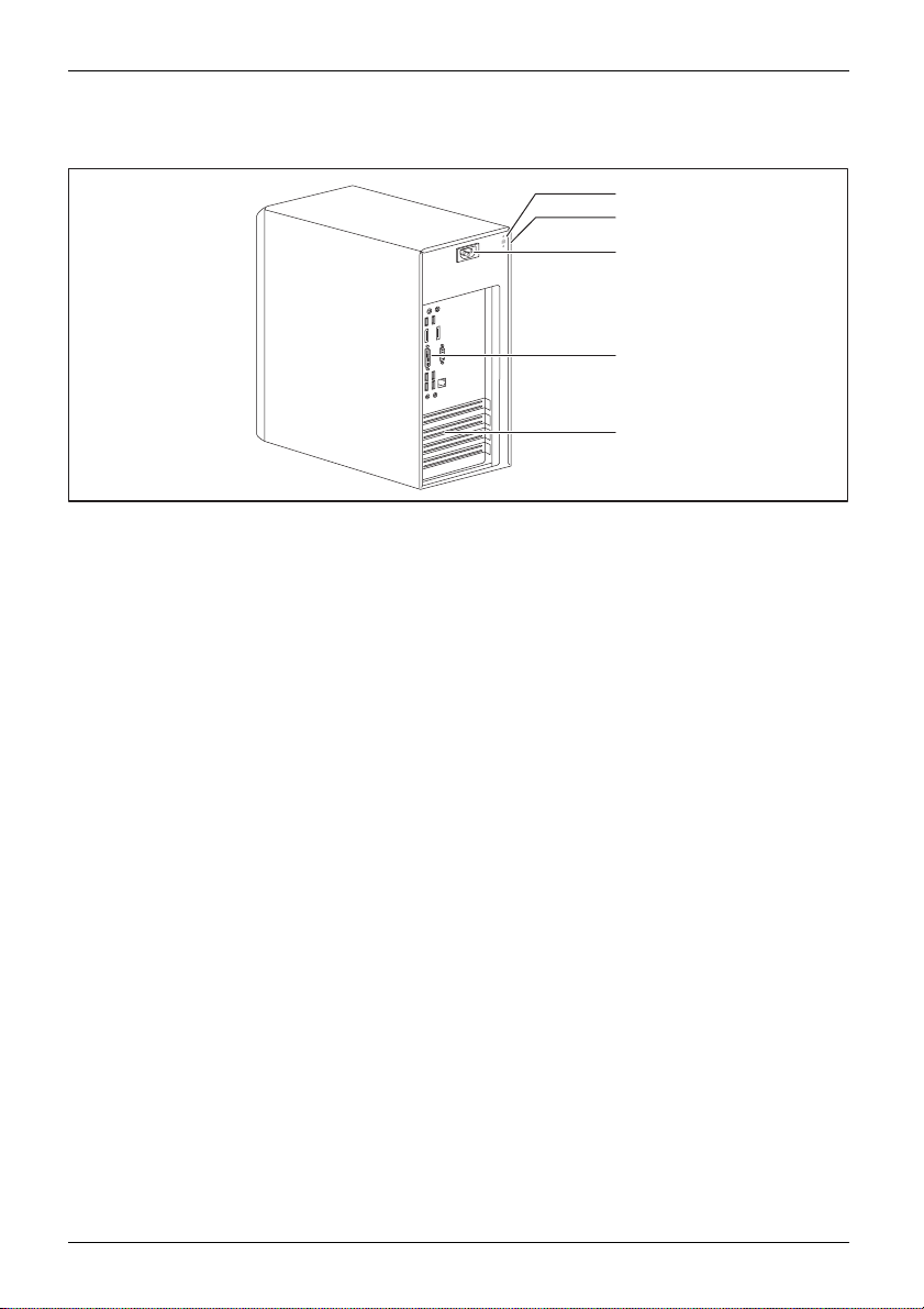
Rear
1
2
K
3
4
5
1 = Device for a Securi
2 = Holes for a padlock
3=Alternatingvolt
age socket (AC IN)
ty Lock
4 = Ports for external
(device-dependen
5 = Slot covers
devices
t)
10 Fujitsu
Page 15

Important notes
ImportantnotesNotes
In this chapter you will find information regarding safety which it is essential to
take note of when working with your device.
Safety information
SafetyinformationNote
Please note the inform at
and in the following safe
When installing and ope
environmental conditi
the instructions in Cha
When setting up the dev
thecasingreceives
cover the ventil ati
You must only opera
device is set to the
The main switch (if
device from the ma
voltage, remove t
Only operate th
Replace the lit
in "
Replacing t
Caution, comp
The activiti
performed wi
Repairs to th
Incorrect r
to the equi
e device with the casing closed.
hium battery on the mainboard in accordance with the instructions
he lithium battery", Page 81.
onents in the system can get very hot.
es described in these instructions must always be
th the greatest care.
e device must only be performed by qualified technicians.
epairs could put the user at great risk or cause serious damage
pment (electric shock, risk of fire).
ion provided in the "Safety/regulations" manual
ty notes.
rating the device, please observe the no tes on
ons in Chapter "
pter "
Getting start ed", Page 13.
Technical data", Page 82 as well as
ice, make sure there is clearance all around it so that
enough ventilation. I n order to avoid overheating, do not
on areas of the monitor or the device.
te th e device if the rated voltage used by the
local mains voltage.
present) and the ON/OFF switch do not disconnect the
ins voltage. To completely disconnect from the mains
he power plug from the power socket.
Important notes
Transpor
rtation
portation
Device,Transpo
Retrans
ting the device
Transport all parts separately in their original packaging or in a packaging which
protects them from knocks and jolts, to the new site.
Do not unpack them until all transportation manoeuvres are completed.
If the device is brought from a cold environment into the room where it will be used,
condensation may occur. Before operating the device, wait until it is absolutely dry
and has reached approximately the same temperature as the installation site.
Fujitsu 11
Page 16

Important notes
Cleaning the device
Device,TransportationRetransportationSystem unit,seeDevice
Turn off all power and equipm ent switches and disconnect the power
plug from the m ains outlet.
Do not clean any interior parts yourself, leave this job to a service technician.
Do not use any cleaning agents that contain abrasives or ma y corrode
plastic (alcohol, thinner or acetone).
Never clean the device with water! Water entering into the device could
present a serious risk to users (e.g. electric shock).
Ensure that no liquid enters the system.
The surface can be clea
moistened in mild dome
Use disinfectant wi
ned with a dry cloth. If particularly dirty, use a cloth that has been
stic detergent and then carefully w rung out.
pes to clean the keyboard and the mouse.
Energy saving, disposal and recycling
DisposalEnergysavingRecycling
You c an findinformationonthesesubjectsinthe"Environment and Energy Information" manual
or on our website ("
http://www.fujitsu.com/fts/about/fts/environment-care/").
12 Fujitsu
Page 17

Getting started
Getting started
Gettingstarted
Unpacking and checking the delivery
It is recommended not to throw away the original packaging material! It may be
required for reshipment at some later date.
PackagingContentsofdeliveryPackaging,
► Unpack all the individual parts.
► Check the contents of the package for any visible damage caused during transport.
► Check whether the delivery conforms to th e details in the delivery note.
► Should you discover that the delivery does not correspond to the delivery
Steps for initial setup
Preparingforfirstuse,overvie wPreparingforuse,
Only a few steps are necessary to put your new device into operation for the first time:
• Select a location for device and set up device
• Connect external devices such as mouse, keyboard and monitor
• Check the voltage at the mains outlet and connect the device to an electrical outlet
• Switch the device on
You will learn more about the individual steps in the following sections.
Please observe the safety information in the "Importa nt notes", Page 11 chapter.
note, notify your local sales outlet immediately.
External devices
If you have received other external devices in addition to your own device (e.g.
a printer), do not connect these until after the initial installation. The following
sections describe how to connect these exte rnal devices.
Drives and boards
If you have received drives or boards with your device, please do not install
them until after first-time setup. How to install drives an d boards is described
System expansions", Page 33 chapter.
in the "
Fujitsu 13
Page 18

Getting started
Setting up the device
WorkstationErgonomicDevice
When installing your device, please read the recommendations and safety
notes in the "Safety/regulations" manual.
We recommend that you place your device on a surface which is not slippery. In
view of the many different finishes and varnishes used on furniture, it is possible
that the rubber feet will mark the surface they stand on.
Depending on the location of your device, bothersome vibrations and noises may
occur. To prevent this, a distance of at least 10 mm / 0.39 in should be m aintained
from other devices on casing sides w ithout ventilation surfaces.
In order to avoid overheating, do not cover the ventilation areas
of the monitor or the device.
A minim um distance of 200 mm / 7.87 in from the device must be
observed for ventilation areas.
Do not stack several devices on top of each other.
Do not expose the device to extreme ambient conditions (see "
section "Ambient conditions"). Protect the device against dust, humidity and heat.
Technical data", Page 82,
14 Fujitsu
Page 19

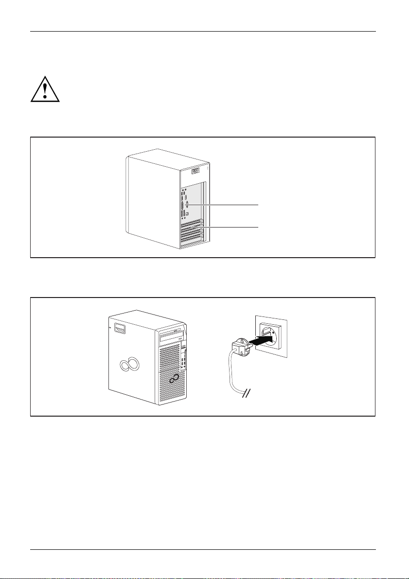
Connecting the device to the mains supply
Mainsadapter
Use the following table to check which mains plug applies for your country. The
following illustration may be different from your co untry variant.
1
2
Getting started
► Connect the pow
er cable to the device (1).
► Plug the power plug into a grounded mains outlet (2).
Power connection
Country
USA, Canada, Mexico, parts of South America,
Japan, Korea, the Philippines, Taiwan
Russia and the Co mmonwealth of Independent
States (CIS), large parts of Europe, parts of
South America, the Middle East, parts of Africa,
Hong Kong, India, large parts of South Asia.
UK, Ireland, Malaysia, Singapore, parts of Africa
China, Australia, New Zealand
Fujitsu 15
Page 20

Getting started
Connecting external devices
Read the documentation on the external device before connecting it.
With th e exception of USB devices, always remove all power plugs
before connecting external devices!
Do not connect or disconnect cables during a th understorm.
Always take hold of the actual plug when disconnecting a cable. Never pu ll the cable!
To ensure that your device works properly, use only the supplied connection
cable or only use a high-quality connection cable.
16 Fujitsu
Page 21
Getting started
LAN
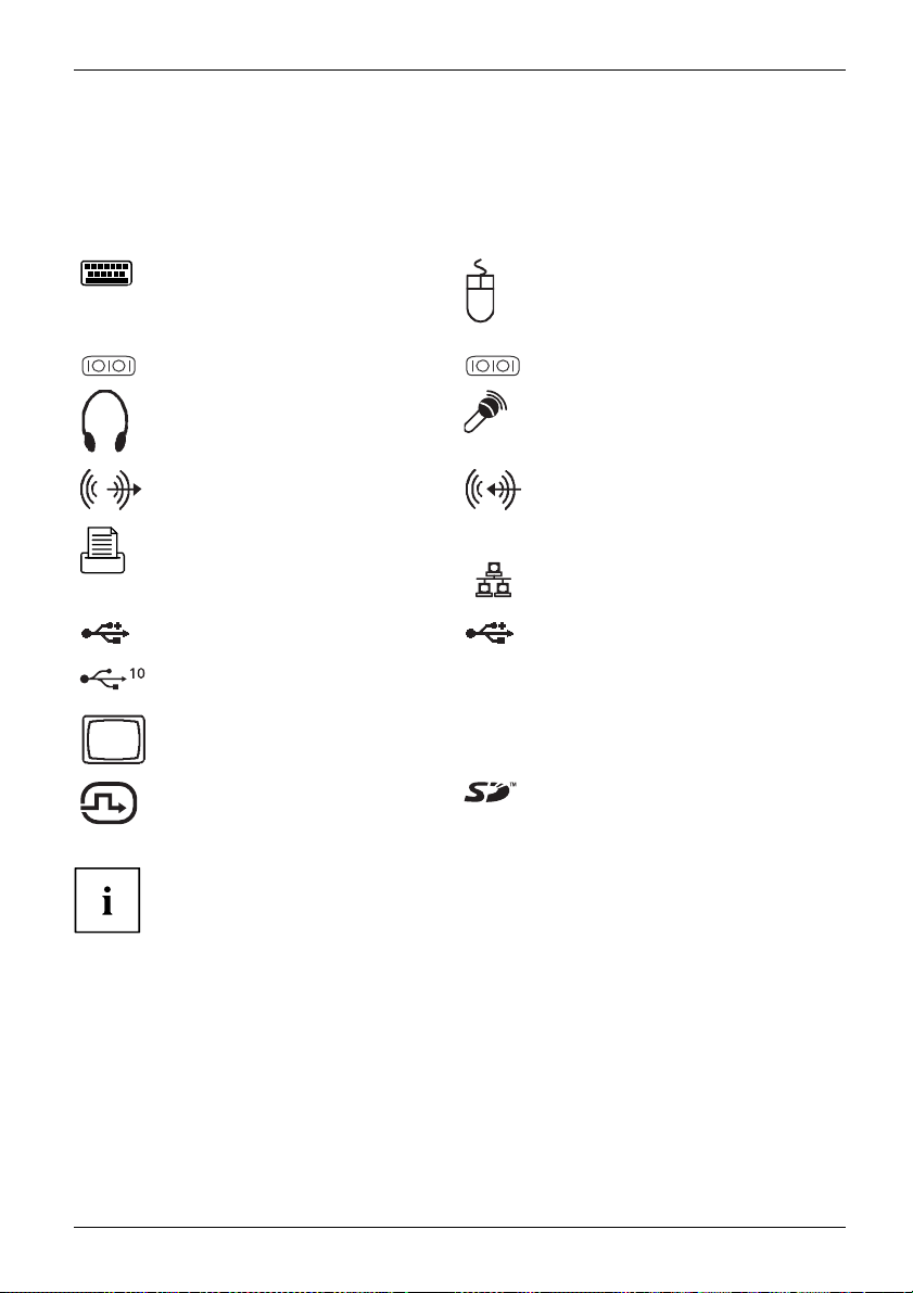
Ports on the device
PortsExternaldevicesDevice
The ports are located on the front and back of the device. The ports available on your
device depend on the configuration level you have selected. The standard ports are
marked with the symbols shown below (or similar). Detailed information on the location
of the ports is provided in the m anua l for the mainboard.
PS/2 keyboard port, purple
Keyboardport
PS/2 mouse port, g reen
MouseportPS/2mouseport
1
Serial port 1, turquoise
Serialport
2
Headphones, light g reen (back
of device) or black (front of
device)
Headphones
Audio output (Line out), light
green
AudiooutputLineou t
Parallel port/printer (optional)
ParallelportPrinter
USB 3.1 - Universal Serial Bus,
type A: blue, type C
UniversalSerialBus
TM
:black
Serial port 2, turquoise
Serialport
Microphone port, pink (back of
device) or black (front of device)
Microphonejack
Audio input (Line in), light blue
AudioinputLinein
LAN port
LANport
USB type 2.0 - Universal S eri al
Bus, black
USB 3.1 G en2 - Universal Serial
Bus, type A: blue, type C: black
VGA monitor connection, blue
Monitorport
DVI-I monitor port
DP DisplayPort
SD Card (slot for memory cards
in the format Secure Digital
Card)
Some of the connected devices require special software (e.g. drivers) (refe r to the
documentation for the connected device a nd operating system).
Fujitsu 17
Page 22
Getting started
Connecting a monitor
Only connect the screen to your device w hen it is switched off.
Depending on requirements, you can use the monitor ports of the mainboard (1) or the monitor ports
of an optional display adapter in one of the board slots (2) to connect a monitor to your device.
K
1
2
► Follow the instructions contained in the monitor m anual to prepare the monitor
for operation (e.g. connecting cables).
► Connect the data cable to a suitable monitor port of the device (VGA, DVI-I, DisplayPort).
1
► Depending on the connector and configuration level of your device, plug the
monitor power cable into an earthed mains outlet (1).
18 Fujitsu
Page 23

Getting started
Connecting the mouse
You can connect a USB mouse or a PS/2 mouse to your device.
Mouse,Connecting,
Connecting a USB mouse
► Connect the USB m ouse to one of the USB ports on the device.
USBport,USBport
Connecting a PS/2 mouse
► Connect the PS/2 mouse to the PS/2 mouse port of the device.
PS/2mouse,Connecting,PS/2mouse,
Connecting the keyboard
Depending on the equipme
a USB keyboard or a PS/2 k
Keyboard,Connecting,
Connecting a USB keyboa
Use the supplied keyboard cable only.
USBport,Connecting,
► Plug the rectangular connector of the keyboard cable into the rectangular socket
on the underside or on the rear of the keyboard.
► Plug the flat rectang
USBport
Connecting a PS/2 keyboard
Use the supplied ke
ConnectingaPS/2keyboardConnecting,
► Plug the rectang
on the underside
► Plug the round connector of the keyboard c able into a keyboard port of the device.
Keyboard,
nt level selected, your device will be supplied with
eyboard.
rd
ular USB connector of the keyboard cable into a USB port of the device.
yboard cable only.
ular connector of the keyboard cable into the rectangular socket
or on the rear of the keyboard.
Connecting external devices to the parallel or serial interface (optional)
ParallelportSerialportParallelportSerialportExternaldevicesDevices
External devices can be connected to the parallel or serial port (e.g. a printer or a scanner).
► Connect the data cable to the external device.
► Depending on the device, connect the data cable to the parallel port or the serial port.
For an exact description of how to connect external devices to the corresponding
port, please refer to the documentation of the external device.
Port settings
ParallelportSerialport,
You can change the port settings (e.g. address, interrupt) in the BIOS Setup.
Fujitsu 19
Page 24

Getting started
Device drivers
DevicedriversDevice drivers,
The devices connected to the para llel or serial port require drivers. Your operating
system already includes many drivers. If the required drive is missing, install it. Current
drivers are usually available on the Internet or will be supplied on a data carrier.
Connecting external devices to the USB ports
USBdevices,USBport,Externaldevices,De vices,
You can connect a wide rang
printer, scanner, mouse o
e of external devices to the USB ports (e.g.
r keyboard).
USB devices are hot-plug
USB cables while your dev
Additional informatio
gable. This means you can connect and disconnect
ice is switched on.
n can be found in the documentation for the USB devices.
► Connect the data cable to the external device.
► Connect the data c able to one of the USB ports on your device.
Device drivers
External USB devices which you connect to one of the USB ports don’t usually
need their own drivers because the software required is already included in
the operating system. If the device requires separate software, please follow
the instructions in the manufacturer ’s documentation.
Switching on for the first time: installing the software
Installing,Software,Installing,
Once the installation has been started the device must not be switched
off, unless the installation has been completed.
During installation, the device may only be rebooted when you are re quested to do so!
The installation will otherwise not be carried out correctly and the contents
of the hard disk must be completely restored.
If the device is integrated into a network, the user and server details as well as
the network protocol are required during the software installation.
Contact your network administrator if you have a ny questions about these s ettings.
When you switch on the device for the first time, the supplied software
is installed and configured. Plan a reasonable amount of time for this,
as this process must not be interrupted.
20 Fujitsu
Page 25

Switch on the monitor and the machine
In order to avoid overheating, do not cover the ventilation areas
on the monitor or the device.
► Switch on the monitor (see operating instructions for the monitor).
Getting started
► Press the on/off
The operational display will light up and the machine will start.
button on the front of the machine.
Installing the software
► During installation, follow the on-screen instructions.
Software,Installing,
► If anything is unclear regarding the data you are asked to input, read the
online Help in your operating system.
You will find more information on the system, as well as drivers, utilities
and updates on the optional "Drivers & Utilities" DVD and on the
Internet at "
You c a n find information and help on the Windows operating system functions
on the Internet at "
http://www.fujitsu.com/fts/support".
http://windows.microsoft.com".
Fujitsu 21
Page 26

Operation
Operation
Switch the device on
► If necessary, switch the monitor on (see the operating manual for the monitor).
DeviceMonitor
► Press the ON/OFF switch on t
The power indicator glows and the device is started.
Switching off the device
Switching the device o
disconnect the mains
► Shut down the operating system in the proper way.
DeviceMonitor
The devices switches to power saving m ode automatically and switches off.
he front of the device.
ff does not disconnect it from the mains voltage. To completely
voltage, remove the power plug from the power socke t.
Procedureinane
If the device cann ot be switched off, you can force a shutdown by
using the following emergency procedure.
Warning, this could lead to a loss of data!
► Press the ON/O F F switch for at least 4 seconds.
The device will switch off.
When you next restart the device, error messages may be displayed
due to the improper shutdown.
mergency
22 Fujitsu
Page 27

Operation
Indicators on the device
The indicators are o n the front of the casing. Which indicators are available on your
device depends on the configuration level you have selected.
1
2
3
4
No. indicator Description
1, 2 Drive indicators
3 Power-on indicator Warning: In the energy saving mode, the device must not be
4 Hard disk indicator
The indicators light up when the Slim-Line drive or CD-ROM or
DVD drive of the device is accessed. You must never under any
circumstances remove the CD/DVD while the indicator light is on.
disconnected from the mains, as this can result in a loss of data.
• Indicator is illuminated:
The device is switched on.
• The indicator flashes (depending on device type):
The device is in energy-saving mode. After being switched on
with the ON/OFF switch, the device powers up or returns to the
state it was in be fore it entered energy-saving mode.
• The indicator is not illuminated:
The device is switched off or disconnected from the mains. If
the device is ready for operation, it can be switched on with
the ON/OFF switch.
The indicator lights up wh en the hard disk drive of the device is
accessed.
Fujitsu 23
Page 28

Operation
Keyboard
KeyboardKeyboard,Keyboard,Keyboard,Keyboard,Keyboar d,Alphanumeric keypadCursorkeysKeys,FunctionkeysNumerickeypadNumerickeypad
The illustrated keybo ard is an example and may differ from the model you use.
1 2
345
1 = Function keys
2 = On/off switch (optional)
4=Cursorkeys
5 = Numeric keypad (calculator keypad)
3 = Alphanumeric keypad
Important k
KeysKeyb oardshortcuts
eys and keyboard shortcuts
The description of the following keys and keyboard shortcuts applies to Microsoft
operating systems. Details of other keys and keyboard shortcuts can be found in
the documentation for the relevant application pro gram.
Key / key combinatio n Description
tch
ON/OFFswi
Button,
On/off sw itch (option al)
Depending on the setting in the BIOS Setup, the device can be switched
on or off with this switch. Some operating systems allow you to configure
additional functions of the ON/O F F switch in the Control Pan el.
WithsomekeyboardstheON/OFFswitchcanonlybeusedwithanACPI
(Advanced Configuration and Power Management Interface). Otherwise
the key is inoperative. The mainboard must support this function.
Keys,Keys,Keys,
Enter key
confirms the highlighted selection. The Enter key is also referred to as
the "Return" key.
24 Fujitsu
Page 29

Operation
Key / key combination Description
Keys,
Windows key
calls up the Windows Start menu
Keys,
Menu key
calls up the menu for the marked item (Windows).
Keys,Keys,
Shift key
enables upper-case lett
Keys,
Alt Gr key (country-dep
produces a character s
sign on the
Keys,
Num Lock key
By pressing the Num L
lower-case levels
When the Num Lock in
keys are active.
When the Num Lock i
Numeric keypad a
Keys,KeysKeysKeys,
Ctrl key
Ctrl
performs a special operation when pressed in conjunction with another
key. The
Ctrl+Alt+DelCtrl+Alt+DelKeyske yboardshortcuts
Ctrl
Windows Security/Task Manager
AltCtrl
++
Del
This key combination opens the Windows Security/Task Manager window.
.
ers and the upper key symbols to be displayed.
endent)
hown on the bottom right of a key (e.g. the @
Q
key).
ock key you switch betw een the upper- and
of the calculator keypad.
dicator is lit the numeric keypad and arithmetic
ndicator is not lit the cursor control functions on th e
re active.
key is also called the "Control" or "Control key".
Settings in BIOS Setup
ttings,
BIOSSetup,Systemse
BIOSSetup,BIOSSetup,BIOSSetupSetup,
In BIOS Setup, you can set the system functions and the hardware con figuration of the device.
When the PC is delivered, the default entries are valid (see "BIOS Setup" manual or manual for
the mainboard). You can customise these settings to your requirements in the BIOS Setup.
Fujitsu 25
Page 30

Operation
Property and data protection
PropertyprotectionDataprotectionSecuritymeasures
Software functions and mechanical locking offer a broad range of functions for protecting your device
and your personal data against theft and unauthorised access. You can also combine t hese functions.
Anti-theft protection and lead-sealing
Device,Device,Casing,Lead-sealingAnti-theftprotectionKensingtonLockChain
K
K
1
1 = Holes for a padl
ock
K
K
2
2 = Device for a security lock
26 Fujitsu
Page 31

Operation
Anti-theft protection
You can protect your device from theft
• with the holes (1) and a padlock and chain which you have connected to a fixed object beforehand.
• with the Security Lock device (2) and a Kensington MicroSaver. Please
consult the manual for your Security Lock.
Lead-sealing
To prevent unauthorised persons from opening the casing, the casing can be lead-sealed. To do
this, feed the sealing chain through the holes (1) and seal the chain with the lead seal.
Mechanical casing lock (optional)
CasingmechanicallockCasingLockCasinglock
With the casing lock you
from opening it. The k
FUJITSU Workstatio
with a casing lock, t
secured against una
can mechanically lock the casing to prohibit unauthorised persons
eys ca n be found on the rear panel of your device.
n CELSIUS W570power+ / W580pow er+: If you have a casing
he cover of the drive cage on the front of the device is also
uthorised opening when th e lock is locked.
Inadditiontothe
casing lock, an open
• Key turned towar
ds the closed lock: The device is locked.
and a closed lock are also illustrated.
• Key turned towards the open lock: The device is unlocked.
Fujitsu 27
Page 32

Operation
Locking the casing
► Turn the key towards the closed lock .
Unlocking the casing
► Turn the key towards the open lock .
BIOS setup security functions
SecurityfunctionsBIOSSetup
The Security menu in BI
personal data agains
• Prevent unauthoriz
• Prevent unauthorised system access
• Prevent unauthori
• Activate virus warnings
• Protect BIOS from
• Protect the device from being switched on by an external device
You can also comb
You will findad
in the manual f
or the mainboard or in the "BIOS Setup" manual.
OS Setup offers you various options for protecting your
t unauthorized access, e.g.:
ed access to BIOS Setup
sed access to the settings of boards with their own BIOS
overwriting
ine these functions.
etailed description of the Security menus and how to assign passwords
Access authorisation via SmartCard
SecurityfunctionsAccesspermission,SmartCard
In systems equipped with a SmartCard reader, access can be restricted to those
users who have a corresponding SmartCard.
Operating the SmartCard reader (optional)
Operation of a SmartCard reader with a RFID reader is not permitted in Taiwan.
► Connect the external SmartCard reader to your system as described in
the instructions for the SmartCard reader.
ardreader,
SmartC
After the device is switched on, you will be prompted to insert your SmartCard.
28 Fujitsu
Page 33

Troubleshooting and tips
Refer to the safety notes in the "Safety/ regulations" manual and in the "Getting
started", Page 13 chapter when connecting or disconnecting cables.
Troubleshooting and tips
If a fault occurs, try to c
• in this chapter
• in the documentation for the connected devices
• in the help systems of th
• in the documentation for your operating system
orrect it as described in the following documentation:
e software used
Help if problems occur
Should you encount
► Note the ID number
plate on the back,
► Contact the Service Desk r esp onsible for your country for clarification of the problem:
"
http://support.ts.fujitsu.com/contact/ser vicedesk". When you do this, please have
ready the ID number and serial number of your system.
er a problem with your computer that you cannot resolve yourself:
of your device. The ID number is found o n the type rating
the underside or the top of the casing.
Troubleshooting
Power-on indicator remains unlit after you have switched on your device
Cause
The mains voltage supply is faulty. ► Check whether the power cable is plugged
Internal power supply overloaded.
Troubleshooting
properly into the device and a grounded
mains outlet.
► Pull the power plug of the device out of the
mains outlet.
► Wait app
► Plug the power plug into a properly grounded
mains outlet again.
► Switc
rox. 3 min.
h the device on.
Fujitsu 29
Page 34

Troubleshooting and tips
The device cannot be switched off with the On/Off switch.
Cause
System crash ► Press the On/Off switch for at least
Troubleshooting
4 seconds, until the device switches off.
Attention: Warning, this could lead to a loss of
data!
The Operating System is not shut-down properly
in the process. Error messages are therefore
possible the next time the system is booted.
Monitor remains b lank
Cause
Monitor is switched off ► Switch your monitor on.
Power saving has been activated (screen is
blank)
Brightness control is set to dark ► Adjust the brightness control. For detailed
Power cable not connected
Monitor cable not connected
Incorrect setting for the monitor
Remedy
► Press any key on the keyboard.
or
► Deactivate the screen saver. If
necessary, enter the appropriate
password.
information, please refer to the operating
manual supplied with your monitor.
► Switch off the monitor and the device.
► Check that the monitor power cable is
properly connected to the monitor and to
a grounded mains outlet or to the monitor
socket of the device.
► Check that the device power cable is
properly plugged into the device and a
grounded mains outlet.
► Switch on the monitor and the device.
► Switch of
► Check that the monitor cable is properly
connected to the device and monitor.
► Switch o
► Restar
► Press
► Start
► Set up the monitor as described in the
documentation for your operating system
and monitor.
f the monitor and the device.
n the monitor and the device.
t the system.
8
F
while the system is booting.
the system in Safe Mode.
30 Fujitsu
Page 35

Troubleshooting and tips
No mouse pointer displayed on the screen
Cause
The mouse is not correctly connected.
Disabled USB ports ► In the BIOS Setup, check w hether the USB
Remedy
► Shut down your operating system in the
proper manner, for instance using
Alt+Del
► Switch the device off.
► Check that the mouse cable is properly
connected to the system unit. If you use an
adapter or extension lead with the mouse
cable, check the connections.
► Make sure that only one mouse is
connected.
► Switch the device on.
ports are Enabled (see the "BIOS Setup"
manual or the mainboard manual
.
Ctrl
Time and/or date is not correct
Cause
Time and date are incorrect.
The lithium battery is discharged.
Remedy
► Set the correct ti
operating syste
or
► Set the correct time and/or date in the
BIOS Setup.
► If the time and
when you switc
lithium batt
battery", P
me and date within the
m you are using.
date are repeatedly wrong
h on your device, replace the
ery (see "
age 81).
Replacing the lithium
+
Error mess
Error messages and their explanations are provided:
• in the technical manual for the mainboard
• in the doc
ages on the screen
umentation for the programs used
Installing new software
When installing program s or drivers, important files may be overwritten and modified. To
be able to access the original data in the event of any problems following installation,
you should backup your hard disk prior to installation.
Fujitsu 31
Page 36

Troubleshooting and tips
Tips
Top i c Tip
Out of system resources ► Close unnecessary applicatio
or
► Run the applications i n a different order.
ns.
32 Fujitsu
Page 37

System expansions
System expansions
Upgrades,Device,SystemexpansionComponentsServicing
After consulting the Hotline/Service Desk, you may remove and install the
components described in this manual yourself.
The following illustrations may differ slightly from your device, de pending on its configuration level.
Nachfolgend ist in der Regel die FUJIT SU Workstation CELSIUS W 570powe r+ /
W580power+ abgebildet. A uf Unterschiede zwischen den drei Gerätevarianten FUJITSU
Workstation CELSIUS W570 / W580, FUJITSU Workstation CELSIUS W570 power /
W580power und FUJITSU Workstation CELSIUS W570power+ / W580power+ wird
in den entsprechenden Abschnitten hingewiesen.
If further documentation was delivered with your device, please also read this through carefully.
In addition, before removing or installing system components, please pay attention to the following:
Repairs to the device must only be performed by qualified technicians. Incorrect repairs
may greatly endanger the user (electric shock, fire risk) and will invalidate your warranty.
As the device has to be shut down in order to install/deinstall system hardware
components, it is a good idea to print out the relevant sections of this chapter beforehand.
The device must be switched off when installing/removing the system
expansions and may not be in energy-saving mode.
Remove the po w er plug before opening the device.
Be careful that no wires become trapped when removing or installing components.
When installing components that become very hot, make sure that the maximum
permissible temperature of the components in operation is not exceeded.
An update of the BIOS may be required for a system expansion or hardw are
upgrade. Further information can be found in the BIOS help section or if
necessary in the Technical Manual for the mainboard.
Fujitsu 33
Page 38

System expansions
Information about boards
Take care with the locking mechanisms (catches and centring pins) when you
are replacing boards or components o n boards.
Note that so me components on the mainboard may b e very hot if the device was
in use shortly before the casing was removed.
To prevent damage to the board or the components and conductors on it, please take care when
you insert or remove boards. Make sure expansion boa rds are inserted straightly.
Never use sharp objects (screwdrivers) for leverage.
Boards with electrostat
shown.
When handling boards fit
following points:
• You must always disc
object) before work
• The equipment and tools you use must be free of static charges.
• Only touch or hold t
marked green (Touc
• Never touch pins or conductors on boards fitted with ESDs.
ic sensitive devices (ESD) are identifiable by the label
ted with ESDs, you must always observe the
harge static build up (e.g. by touching a grounded
ing.
he boards by the edge or, if prese nt, at the areas
h Points).
34 Fujitsu
Page 39

Opening the casing
Casing,Device,
► Switch the device off. The device must not be in power-saving mode.
Please observe th e safety information in "Important notes", Page 11.
Disconnect the mains plug from the mains outlet.
Only insert the power plug after you have closed the casing.
System expansions
► Remove any connected wir
es which are in the way.
► On devices with a casing lock: Unlock the casing.
► Lay the device on its sid
e in the manner shown.
1
2
► Pull the locking device (1) and swivel the side part in the direction of the arrow (2).
Fujitsu 35
Page 40

System expansions
Closing the casing
► Insert the side part in the guide rail on the lower part of the casing.
Casing,Device,
During the installation, make sure that you insert the detent (a) into the corresponding
opening on the housing (b). Othe rwise the casing cannot be closed.
1
a
b
► Swivel the sid
e cover in the d irection of the arrow (1) until it engages.
► Ondeviceswithacasinglock: Lockthecasing.
► Reconnect th
e cables that you disconnected before.
36 Fujitsu
Page 41

Open and c lose the drive cage (only for
the model FUJITSU Workstatio
n CELSIUS
W570power+ / W580 power+)
For some of the work steps des
CELSIUS W570power+/ W580p
opened and, if necessary
cribed below, the FUJITSU Workstation
owert+ requires that the drive cage should be
, also pulled out of the casing.
System expansions
Fujitsu 37
Page 42

System expansions
1
Open the drive cage
► Open the casing (see "Opening the casin g", Page 35). Otherwise , the cover on the drive
cage cannot be removed since it is a lso secured by the casing lock.
2
► Access this from the side, reaching into the opening on the drive cage (1).
► Remove the cover (2).
1
3
► Release the lever from the cover (1).
► Pull the lever (2).
► Fold the cover in the direction of the arrow (3).
38 Fujitsu
2
Page 43

Pull the drive cage out of the casing.
► Open the drive cage (see "Open the drive cage", Page 38 ).
1
► Fold upwards the lever on the drive cage (1).
► Pull the drive cag
e out of the casing using the lever (2).
System expansions
2
Fujitsu 39
Page 44

System expansions
Slide t he drive cage into the housing.
2
► Slide the drive cage into the housing (1).
► Fold the lever on the drive cage back into the cage (2).
► Close the drive cage (see "
Close the drive ca ge", Page 41).
1
40 Fujitsu
Page 45

Close the drive cage
► Fold the cover upwards (1).
► Attach the lever to the c over (2).
System expansions
2
1
1
► Position the cover on the drive cage (1).
► Close the casing (see "
Fujitsu 41
Closing the casing", Page 36).
Page 46

System expansions
Overview of the drive bays and drives in your device
The casing has space for several accessible and non-accessible drives:
• One installation slot for a slim-line drive
• One installation slot for an accessible 5
• One installation slot for a M.2 module
• Non-operable hard disk drives, depending on the device variant and the version level /
installation kit used ("
"Accessible drives" are e.g. DVD or CD ROM drives, into which a data medium can be
inserted from outside. "Non-accessible drives" are for example hard disk drives.
Overview of the hard disk drives", Page 48)
1
/4-inch drive
Install and remove the slim-line drive
Installing an accessible drive
To use the locking function of the slimline drive, you must fit the appropriate drive
plate on the drive before installing the drive in the casing.
► Open the casing ( see "
► If you have already fitted a cover (optional), remove it.
Opening the casing", Page 35).
Do not throw away the cover. For cooling and protection aga inst fire you must refitthe
cover if you remove the drive again later (see "
a a
1
1
► Take the drive cover (a) out of the holder in the direction of the arrow (1).
► Attach the drive cover (a) to the slim-line drive (b).
42 Fujitsu
Removing an accessible drive", Page 47).
b
Page 47

2
► Slide the drive into the housing (2) until it slots into place in the lock (c).
► Close the casing (see "
It may be necessary to modify the entry for the drive in the BIOS Setup.
Closing the casing", Page 36).
Removing an accessible drive
► Open the casing (see "Opening the casing", Page 35).
System expansions
c
2
3
a
► Press the release button (1).
► Press t
► Pull t
Fujitsu 43
he clip (a) in th e direction of the arrow (2).
The drive will be pushed forward out of the slot.
he drive out of the c asing in the direction of the arrow (3).
1
Page 48

System expansions
b b
4
► Remove the drive cover (b) from the drive (c).
► Insert the drive cover in the direction of the arrow (4) into the holder.
► If necessary, make the required se ttings on the remaining hard disk drives.
► If you are not installing a new drive, reinstall the previously removed cover (optional) for the
purposes of cooling, fire protection and to prevent foreign objects from getting into the casing.
► Close the casing (see "
It may be necessary to modify the e ntry for the drive in the BIOS Setup.
Closing the casing", Page 36).
c
44 Fujitsu
Page 49

System expansions
Installing and removing the accessible 51/4inch drive
1
/4inch drive
Fitting the drive cover for th
To use the latch function of the accessible 51/4inch drive, you must fit the corresponding
drive cover before installing the drive in the casing. Proceed as follows:
► Open the casing (see "
► Remove the drive cover from the bracket in the direction of the arrow (1).
Opening the casing", Page 35).
1
e5
► Connect the drive cover to the drive (1).
1
Fujitsu 45
Page 50

System expansions
Installing an accessible drive
► Open the casing ( see "Opening the casing", Page 35).
► Break out the pre-cut plastic cover on the drive bay.
► Fit the drive cover for the 5
the 51/4inch drive", Page 45).
► Slide the accessible drive into the casing until it snaps in place (1).
► Connect the cables to the drive. Make sure the polarity is correct.
► Close the casing (see "
It may be necessary to modify the e ntry for the drive in the BIOS Setup.
1
/4inch drive (see "Fitting the drive cover for
Closing the casing", Page 36).
1
46 Fujitsu
Page 51

Removing an accessible drive
► Open the casing (see "Opening the casing", Page 35).
1
► Disconnect the cables connected to the drive.
► Slide the clip in the direction of the arrow (1).
► Pull the drive out of the casin g in the direction of the arrow (2).
► Remove the drive cover from the drive (1).
System expansions
2
1
1
► Place the drive cover on the holder in the direction of the arrow (1).
► If ne
► Close the casing (see "
Fujitsu 47
cessary, make the required settings on the remaining hard disk drives.
Closing the casing", Page 36).
Page 52

System expansions
It may be necessary to modify the e ntry for the drive in the BIOS Setup.
Overview of the hard d isk driv
The EasyChange rails for the installation are provided together with
the particular drive or installation kit.
FUJITSU Workstation CEL
No. Upgrade opt
1
One hard disk, size 2
Disk (SSD)
2
2 hard disks, size 31/2inches
2 hard d
isks, size 21/2inches
SIUS W570 / W570power / W580 / W580power
2
ions
1
/2inches or Solid State
Reference
"Removing and installing 21/2inch hard
disks or Solid State Discs (SSD) (FUJITSU
Workstation CELSIUS W570 / W570power
and W580 / W580power: according to
the operable 51/4inch drive, FUJITSU
Workstation CELSIUS W570power+ /
W580power+: on the drive frame)", Page 59
"Removing and installing hard disks in the
lower part of the device (variants: FUJITSU
Workstation CEL SIUS W570 / W570power /
W580 / W580power)", Page 53
es
1
48 Fujitsu
Page 53

FUJITSU Workstation CELSIUS W570power+ / W580power+
3
The FUJITSU Workstation CELSIUS W570power+ / W580power+ is available in two
variants: with the installation kit 1 (standard) or the installation kit 2 (optional). The table
below therefore also shows the respective installation options for the two installation kits:
System expansions
1
2
Fujitsu 49
Page 54

System expansions
No. Upgrade options
1
2harddisks,size31/2inches
(horizontal)
2harddisks,size21/2inc
(vertical)
4harddisks,size2
(vertical)
2
One hard disk, size 2
inches or Solid State Disk
(SSD)
3
2harddisks,size31/2inches
or
2 hard disks, size 2
1
/2inches
1
/
1
/2inches
Type of device / installation
kit Reference
Installation kit 1 (standard,
cold plug, no disconnecting of
the cables is required)
hes
Installation kit 2 (optional, cold
plug, no disconnecting of the
cables is requ ired)
2
Both installation
kits
Both installation kits (cold
plug, no disconnecting of the
cables is requ ired)
Removing and installing 3
"
1
/2inch hard disks in the
drive cage (only for the
model FUJITSU Works tation
CELSIUS W570 power+ with
installation kit 1 (standard))",
Page 62
The procedure is the same
both installation kits.
"
Installing the hard di
sk drive",
Page 65
"Removing and install
1
/2inch hard disks in t
drive cage (only for t
FUJITSU Desktop CEL
W570power+, with bo
installation kits
Removing and inst
"
21/2inch h ard dis
State Discs (SSD)
Workstation CEL
/ W570power and
/ W580po wer: ac
to the operable
drive, FUJITS
CELSIUS W570p
W580power+: o
frame)", Pag
Removing a
"
disks in th
device (va
Workstati
W570powe
e 59
nd installing hard
e lower part of the
riant: FUJITSU
on CELSIUS
r+, cold plug)",
ing 2
he
he model
SIUS
th
)", Page 65
alling
ks or Solid
(FUJITSU
SIUS W570
W580
cording
51/4inch
U Workstation
ower+ /
n the drive
Page 56
for
50 Fujitsu
Page 55

System expansions
Example: Installation kit 1 (standard, with 2 hard disks horizontal or 2 hard disks vertical)
Installation kit 1 for up to 2 hard disks, size 31/2inches (h orizontal), or up to
2 hard disks, size 2
1
/2inches (vertical):
The hard disks, size 21/2inches (vertical), are also installed like the hard
disks of installation kit 2 shown in the image below.
Fujitsu 51
Page 56

System expansions
Example: Installation kit 2 (optional, with 4 hard disks, max imu m upgrade, vertical)
Drive cage above: Installation kit 2 (optional) for up to 4 hard disks, size 21/2inches (vertical)
52 Fujitsu
Page 57

System expansions
Removing and installing hard di
sks in the lower
part of the device (variants: FUJITSU Workstation
CELSIUS W570 / W570power / W580 / W580power)
The following sections apply both to 31/2inch hard disks and to 21/2inch hard disks.
The on ly difference between 2
is their EasyChange rails.
1
/2inch drive s and 31/2inch drives
Fujitsu 53
Page 58

System expansions
Removing the hard disk drive
► Open the casing ( see "Opening the casing", Page 35).
a
► Disconnect the cables (a) c onnected to the hard disk drive.
► Press the brackets of the EasyC hange rails on the hard disk drive in the direction of the
arrow (1) and pull the hard disk drive out of the drive cage in the direction of the arrow (2).
1
2
a
1
► Pull the EasyChange rails off t he hard disk drive.
► If you no longer need the EasyChange rails, secure them again at their location in the drive cage.
It may be necessary to modify the e ntry for the drive in the BIOS Setup.
54 Fujitsu
Page 59

System expansions
Installing a hard disk drive
► Open the casing (see "Opening the casing", Page 35).
a
a
► Secure the EasyChange rails to the side of the hard disk drive by inserting the
upper pins of the EasyCh ange rail into the c orresponding holes of the hard
disk. The connections (a) face towards the front.
a
► Slide the hard disk drive with the EasyChange rails into the drive cage in the
direction of the arrow (1). Make sure that the hard disk drive connections (a)
are pointing outwards as shown in the diagram.
► Connect the cables to the hard disk drive (a).
► Close the casing (see "
It may be necessary to modify the entry for the drive in the BIOS Setup.
Fujitsu 55
1
Closing the casing", Page 36).
Page 60

System expansions
Removingandinstallingharddi
sks in the lower
part of the d evice (variant: FUJITSU Workstation
CELSIUS W570power+, cold plug)
The following sections apply bo th to 31/2inch hard disks and to 21/2inch hard disks.
The only difference be tween 2
is their EasyChange rails.
Removing the hard disk drive
In the cold-plug process, the cables connected at the back of the drive will be
disconnected automatically when the EasyChange rails are activated, as described below.
► Open the casing ( see "
Opening the casing", Page 35).
1
2
1
/2inch drives and 31/2inch drives
1
► Press the brackets of the EasyC hange rails on the hard disk drive in the direction of the
arrow (1) and pull the hard disk drive out of the drive cage in the direction of the arrow (2).
56 Fujitsu
Page 61

System expansions
► Pull the EasyChange rails off the hard disk drive.
► If you no longer need the EasyChan ge rails, secure them again at their location in the drive cage.
It may be necessary to modify the entry for the drive in the BIOS Setup.
Fujitsu 57
Page 62

System expansions
Installing a hard disk drive
In the cold-plug process, the cables in t he casing for the drive automatically lock
into place when the EasyChange rails are activated, as described below.
► Open the casing ( see "
a
► Secure the EasyChange rails to the side of the hard disk drive by inserting the
upper pins of the EasyChange rail into the correspo ndin g holes of the hard
disk. The connections (a) face towards the rear.
Opening the casing", Page 35).
2
1
2
► Slide the hard disk drive with the EasyChange rails into the drive cage in the
direction of the arrow (1). Ensure that the connections of the hard disk drive
face inwards towards the bottom of the casing.
► Press the levers of the EasyChange rails in the direction of the arrows (2).
► Close the casing (see "
58 Fujitsu
Closing the casing", Page 36).
Page 63

System expansions
It may be necessary to modify the entry for the drive in the BIOS Setup.
Removing and installing 21/
inch hard disks or
2
Solid State Discs (SSD) (FUJITSU Workstation
CELSIUS W570 / W570power and W580 / W580power:
1
/4inch drive,
according to the operabl
e5
FUJITSU Workstation CELSIUS W570power+ /
W580power+: on the drive frame)
The procedure is identical for all three device variants and for both installation kits of
the FUJITSU Workstation CELSIUS W570power+ / W580power+ Only the position
inthecasingisdifferent(see"
The device variant described below is the FU JITSU Workstation
CELSIUS W570power+. / W580power+
For installation in this model, only use the EasyChange rails designed for this
slot. If no suitable drive has already been installed at the time of delivery,
these rails will already be pre-fitted in the s lot.
Overview of the hard disk drives", Page 48):
Fujitsu 59
Page 64

System expansions
Removing the hard disk drive (size: 21/2inches oraSolidStateDisc(SSD))
► Open the casing ( see "Opening the casing", Page 35).
► FUJITSU Workstation CELSIUS
cage (see "
"
Pull the drive cage out of th
► Disconnect the cables connected to the hard disk drive.
► Place the device on its si
Open the drive cage
1
1
W570power+ / W580power+: Open the drive
", Page 38) and pull it out of the casing (see
e casing.", Pa ge 39).
de as shown below.
2
► Press the EasyChange rails slightly together (1).
► Pull the hard disk drive out of the drive cage in the direction of the arrow (2).
► Pull the EasyChange rails off t he hard disk drive.
► If you no longer need the EasyChange rails, secure them again at their location in the drive cage.
► FUJITSU Workstation CELS IUS W570power+ / W580power+ : Reinsert the drive
cage into the casing (see "
close the drive cage (see "
► Close the casing (see "
► Position the device vertically again.
If necessary, y ou must adjust the entry for the drive accordingly in the BIOS setup.
60 Fujitsu
Slide the drive cage into the housing.", Page 40) and
Close the drive ca ge", Page 41).
Closing the casing", Page 36).
Page 65

System expansions
Install a hard disk, size 21/2inches or a Solid State Disk (SSD)
EasyChange rails for the hard disk drive are located on the drive cage.
► Open the casing (see "
► FUJITSU Workstation CELSIUS W570power+ / W580power+ : Open the drive
cage (see "
Pull the drive cage out of the casing.", Page 39).
"
► Place the device on its side as shown below.
► Secure the EasyChange rails on the side of the hard disk (1) by inserting the upper pins
of the EasyChange rail into the corresponding holes of the hard disk.
► Slide the hard disk drive with the EasyChange rails into the drive cage in the direction
of the arrow (2), un til the hard disk is locked in place.
► Connect the cables to the hard disk drive .
► FUJITSU Workstation CELSIU S W570power+ / W580power+: Reinsert the drive
cage into the casing (see "
close the drive cage (see "
► Close the casing (see "
► Position the device vertically again.
Open the drive cage", Page 38) and pull it out of the casing (see
1
1
Opening the casing", Page 35).
2
Slide the drive cage i nto the housing.", Page 40) and
Close the drive ca ge", Page 41).
Closing the casing", Page 36).
If necessary, you must adjust the entry for th e drive accordingly in the BIOS setup.
Fujitsu 61
Page 66

System expansions
Removing and installing 31/2inch hard disks
in the drive cage (only for the
model FUJITSU
Workstation CELSIUS W570 power+ with
installation kit 1 (standard))
If you have ordered a device with installation kit 1, you can replace
1
/2inch hard disks as described below.
3
1
2
/2inch hard disks (vertical) are also installed with installation kit 1 (standard)
like the hard disks in the following sections with installation kit 2 ("
installing 21/2inch hard disks in the drive cage (only for the model FUJITSU
Desktop CELSIUS W570power+, with both installation kits)", Page 65).
Removing the hard disk drive
In the cold-plug process, the cables connected at the back of the drive will be
disconnected automatically when the EasyChange rails are activated, as described below.
Removing and
► Open the drive cage (see "
► Press the brackets of the EasyC hange rails on the hard disk drive in the direction of the
arrow (1) and pull the hard disk drive out of the drive cage in the direction of the arrow (2).
Open the drive cage", Page 38).
1
1
2
62 Fujitsu
Page 67

System expansions
► Pull the EasyChange rails off the hard disk drive.
► If you no longer need the EasyChan ge rails, secure them again at their location in the drive cage.
► Close the drive cage (see "
If necessary, you must adjust the entry for th e drive accordingly in the BIOS setup.
Close the drive ca ge", Page 41).
Installing a hard disk drive
In the cold-plug process, the cables in the casing for the drive automatically lock
into place when the EasyChange rails are activated, as described below.
► Open the dr
Fujitsu 63
ive cage (see "
Open the drive cage", Page 38).
Page 68

System expansions
a
► Secure the EasyChange rails to the side of the hard disk drive by inserting the
upper pins of the EasyChange rail into the correspo ndin g holes of the hard
disk. The connections (a) face towards the rear.
2
1
2
► Slide the hard disk drive with the EasyChange rails into the drive cage in the
direction of the arrow (1). Ensure that the connections of the hard disk drive
face inwards towards the inside of the casing.
► Press the levers of the EasyChange rails in the direction of the arrow (1).
► Close the drive cage (see "
If necessary, y ou must adjust the entry for the drive accordingly in the BIOS setup.
64 Fujitsu
Close the drive ca ge", Page 41).
Page 69

System expansions
Removing and installin g 21/2inch hard disks in the
drive cage (only for the model
FUJITSU Desktop
CELSIUS W570power+, with both installation kits)
The procedure for installat
drives, vertical) is ident
The device variant with i
ical to that of installation kit 2 (up to four 2
ionkit1(fortheinstallationvariantwithuptotwo2
nstallation kit 2 and four drives is shown below.
1
/2inch drives,vertical)
1
/2inch
Installing the hard dis
In the cold-plug process, the cables in the casing for the drive automatically lock
into place when the EasyChange rails are activated, as described below.
► Open the drive cage (see "
a
► Secure the EasyChange rails to the side of the hard disk drive by inserting the upper pins
of the EasyChange rail into the corresponding holes of the hard disk. The connections
(a) point to the rear, the label on the drive points to the right.
kdrive
Open the drive cage", Page 38).
Fujitsu 65
Page 70

System expansions
1
► Press together the EasyChange rails (1) and push the hard disk drive into the drive
cage in the direction of the arrow (2). Ensure that the connections of the hard disk
drive face inwards towards the inside of the casing.
► Close the drive ca
ge (see "
Close the drive ca ge", Page 41).
If necessary, yo
66 Fujitsu
u must adjust the entry for the drive accordingly in the BIOS setup.
Page 71

Removing a hard disk drive
In the cold-plug process, the cables connected at the back of the drive will be
disconnected automatically when the EasyChange rails are activated, as described below.
System expansions
► Open the drive cage (see "
► Press outwards the brackets of the EasyChange rails on the hard disk drive in the direction
of the arrow (1), until the levers move upwards and the hard disk is unlocked.
Open the drive cage", Page 38).
1
1
2
3
2
► Press the levers together again (2).
► Pull the hard disk drive out of the drive cage in the direction o f the arrow (3).
Fujitsu 67
Page 72

System expansions
► Pull the EasyChange rails off t he hard disk drive.
► If you no longer nee
► Close the drive cage (see "
d the EasyChange rails, secure them again at their location in the drive cage.
Close the drive ca ge", Page 41).
If necessary, y ou must adjust the entry for the drive accordingly in the BIOS setup.
68 Fujitsu
Page 73

System expansions
Removing and fitting the front fan
In order to remove or fit long component groups or an M.2 module, it is recommended to
remove the front fan under the front panel while working on the device.
Removing the front fan
► Instructions: Open the casing (see "Op ening the casing", Page 35).
► Disconnect the fan cable
from the mainboard.
1
111
3
2
► Release the detents of the front cover (1).
► Remove the front cover from the casing in the direction of the arrow (2).
► Release the detent (3) and slide the fan away from the casing in the direction of the arrow (4).
You can now remove or install the M.2 module or long modules.
4
Fujitsu 69
Page 74

System expansions
Installing the fro nt fan
1
2
► Attach the fr ont fa
The front fan will then be locked in position.
► Fit the front cove
► Connect the fan cable to the mainboard.
► Close the casing
n to the centering pins on the housing and move it in the direction of the arrow (1).
r onto the casing (2).
(see "
Closing the casing", Page 36).
70 Fujitsu
Page 75

System expansions
Installing and removing a board
You can install additional modules in order to increase the performance of your machine.
The number, position and arrangement of the board slots on the mainboard can be found in
the manual for the mainboard. Boards may already be installed on shipment.
Board,Board,
Installing a board
► For long modules: Remove the front fan (see "Removing and fitting the front fan", Page 69).
► Open the casing (see "
Board
1
2
Opening the casing", Page 35).
a
► Fold the module lock (a) upwards to open it.
► Loosen the screw on the slot c over (1), if one is fitted.
► Pull the slot cover out of the slot in the direction of the arrow (2).
Fujitsu 71
Page 76

System expansions
Do not th row away the slot cover. For cooling, protection against fire and in order to
comply with EMC regulations, you must refit the slot cover if you remove the board.
a
2
1
► Push the board into the slot (1).
► Secure the module with the screw (2), if one is fitted.
► Fold the module lock (a) back down to close it.
► If necessary, connect the cables to the board.
► For long modules: Install the front fan (see "
► Close the casing (see "
Closing the casing", Page 36).
Removing and fitting the front fan", Page 69).
If you have installed or removed a board, please check the relevant PCI
slot settings in the BIOS Setup. If necessary, change the settings. Further
information is provided in the PCI bo ard documentation.
72 Fujitsu
Page 77

System expansions
Removing a board
► For long modules: Remove the front fan (see "Removing and fitting the front fan", Page 69).
► Open the casing (see "
Board
► Disconnect the cables connected to the board.
a
1
3
► Fold the module lock (a) upwards to open it.
► Loosen the scre
Opening the casing", Page 35).
2
w on the module (1), if one is fitted.
Modules in the P
slot with a loc
You can then re
CI Express x16 slot are also secured at the bottom of the
king latch (2). Push the latch to the side to release the card.
move the c ard as described below.
► Pull the slot cover out of the slot in the direction of the arrow (3).
► Place the board in suitable packaging.
Fujitsu 73
Page 78

System expansions
For cooling, protection against fire, and in order to comply with EMC (electromagnetic
compatibility) regulations, you must refit the slot cover.
a
2
1
► Slide the slot cover into the slot (1).
► Secure the slot cover with the screw (2), if one is provided.
► Fold the module lock (a) back down to close it.
► For long modules: Install the front fan (see "
► Close the casing (see "
Closing the casing", Page 36).
Removing and fitting the front fan", Page 69).
If you have installed or removed a PCI board , please check the relevant PCI
slot settings in the BIOS Setup. If necessary, change the settings. Further
information is provided in the PCI bo ard documentation.
74 Fujitsu
Page 79

System expansions
Installing and removing an M.2 m
odule
Installing an M.2 module
► Open the casing (see "Opening the casing", Page 35).
► If necessary, remove the front fan and long component groups f or easier installation (see
Removing and fitti ng the front fan", Page 69 and "Removing a board", Page 73).
"
2
a
► Insert the M.2 module (b) at a slight angle in the direction of the arrow
(1) into the slot (a) on the mainboard.
► Secure the M.2 module on the mainboard with the screw (2).
► If you have removed the front fan and long component groups: Refit these components (see
Removing and fit ting the front fan", Page 69 and "Installing a board", Page 71).
"
► Close the casing (see "
If necessary, you must adjust the entry for the drive accordingly in the BIOS Setup.
Closing the casing", Page 36).
1
b
Fujitsu 75
Page 80

System expansions
Removing an M.2 module
► Open the casing ( see "Opening the casing", Page 35).
► If necessary, remove the front fan and long component groups for easier installation (see
Removing and fitti ng the front fan", Page 69 and "Removing a board", Page 73).
"
1
a
► Undo the screw (1).
► Pull the M.2 module (b) slightly at an angle in the direction of the arrow (2) and out
of the slot (a) on th e mainboard and remove it from the casing.
► If you have removed the front fan and long component g roups: Refit these components (see
Removing and fit ting the front fan", Page 69 and "Installing a board", Page 71).
"
► Close the casing (see "
If necessary, you must adjust the entry for the drive accordingly in the BIOS Setup.
Closing the casing", Page 36).
2
b
76 Fujitsu
Page 81

System expansions
Installing and removing WLAN an
If you have installed a suitable low-profile board , you can install and remove the
associated WLAN antennas as described below.
Operation of WLAN antenn as is not permitted in Taiwan.
tennas
Installing external WLAN antennas
• A suitable board is installed (see "Installing a board", Pag e 71).
2
3
1
3
► Working in the direction of the arrow (1), place the W LAN antennas onto
the plug-in positions of the board (2).
► Secure the WLAN antennas by turning in the direction of the arrow (3).
► Align the WLAN antennas as required.
Fujitsu 77
Page 82

System expansions
Removing external WLAN antennas
► Undo the WLAN antennas by turning in the direction of the arrow (1).
► Pull the WLAN antennas in the direction of the arrow (3) and away from
the plug-in positions of the board (2).
Installing and removing heat sinks
Removing the heat sink
The shape and position o
approach is the same for
► Open the casing ( see "
► FUJITSU Workstation CELSIUS W 570+ / W580power+: Open the drive cage
(see "
Open the drive cage", Page 38) and pull the drive cage out of the casing
Pull the drive cage out of the casing.", Page 39).
(see "
► Disconnect the fan
f the heat sink are device-dependent. The
all variants.
pening the casing", Page 35).
O
cable (FAN (CPU)) from the mainboard.
a
1
► Undo the
► Lift the heat s ink out of the casing (1).
You c a n
78 Fujitsu
screws on the heat sink (a).
now replace the processor (see "
perate the device without a heat sink! Before initial startup, install the heat
Never o
gain in the same way as it was installed in the device before removal.
sink a
Replacing the processor", Page 80).
Page 83

System expansions
Installing the heat sink
► Open the casing (see "Opening the casing", Page 35).
Install the heat sink again in the same way as it was fitted in the
device at the time of removal.
a
1
► Insert the heat sink into the casing (1). In doing so, correctly align the screw holes
on the heat sink with the screw holes on the mainboard.
► Fasten the screws (a).
► Connect the fan leads to the mainboard (FAN CPU).
► FUJITSU Workstation CELSIUS W570+ / W58 0power+: Insert the drive cage
into the casing (see "
the drive cage (see "
► Close the casing (see "
Slide the drive cage into the housing.", Page 40) and close
Close the drive cage", Page 41).
Closing the casing", Page 36).
Fujitsu 79
Page 84

System expansions
Mainboard expansions
Details on how to upgrade the main memory or the processor of your device
can be found in the manual for the mainboard.
UpgradesLithiumbatteryPro cessorMainmemoryMainboard
Upgrading main memory
► Open the casing ( see "Opening the casing", Page 35).
Mainmemory
► FUJITSU Workstation CELSIUS W 570+ / W580power+: Open the drive cage
► Upgrade the main memory according to the description in the manual for the mainboard.
► FUJITSU Workstation CELSIUS W570+ / W580p ow er+: Insert the drive cage
► Close the casing (see "
Replacing the processor
► Open the casing (se
► Remove the heat sink (see "
► Replace the proce
► Install the heat sink again (see "
► Close the casin
Open the drive cage", Page 38) and pull the drive cage out of the casing
(see "
Pull the drive cage out of the casing.", Page 39).
(see "
into the casing (see "
the drive cage (see "
Slide the drive cage into the housing.", Page 40) and close
Close the drive cage", Page 41).
Closing the casing", Page 36).
e "
Opening the casing", Page 35).
Removing the heat sink", Page 78).
ssor as described in the manual for the mainboard.
Installing the heat sink", Page 7 9).
g(see"
Closing the casing", Page 36).
80 Fujitsu
Page 85

System expansions
Replacing the lithium battery
In order to permanently save the system information, a lithium battery is installed to provide
the CMOS-memory with a current. A corresponding error message notifies the user when the
charge is too low or the battery is empty. The lithium battery must then be replaced.
Incorrect replacement of the lithium battery may lead to a risk of explosion!
The lithium battery may be re placed only with an identical battery or with
a type recommended by the manufacturer.
Do not dispose of lithium batteries with household waste. They must be disposed
of in acco rdance with local regulations concerning special waste.
Make sure that you observe the correct polarity when replacing the lithium
battery. The plus pole must be on the top!
Lithiumbattery,Replacing,Re placing,Replacing,lithiumbatteryBattery
The lithium battery holder exists in different designs that function in the same way.
1
2
2
1
3
► Press the catch in the direction of the arrow (1).
The battery jumps o ut of the holder slightly.
► Remove the battery (2).
► Push the new lithium battery of the identical type into the holder (3) and
press it down until it engages.
3
Fujitsu 81
Page 86

Technical data
Technical data
Electrical d ata
Protection class: I
Rated voltage range 100 V – 240 V
Rated frequency
Max. rated current
CELSIUS W570 (250 W)
CELSIUS W570power / W570power+ (360 W)
CELSIUS W580 (250 W)
CELSIUS W580power / W580power+ (360 W)
Dimensions
Height/width/depth: 180 mm x 313 mm x 374 mm /
Weight
in basic configuration (configuration dependent: about 7.5 kg /
Ambient conditions
Environment class 3K2
Environment class 2K2
Temperature
Operation (3K2) 10 °C .... 35 °C / 50 °F ... 95 °F
Transportation (2K2) -25 °C .... 60 °C / -3 °F ... 140 °F
The formation of condensation is not permitted while the device is in operation !
Clearance required to ensure adequate ventilation:
without air vents
with air vents
50Hz–60Hz
100 V – 240 V
3.3 – 1.3 A
4.4 – 1.8 A
3.5 – 1.5 A
4.6 – 2.1A
7,09 in x 12,32 in x 14,72 in
16,5 lbs
DIN IEC 721 part 3-3
DIN IEC 721 part 3-2
at least 10 mm /
0,39 in
at least 200 mm /
7,87 in
The data sheets of these devices contains further technical data. The data sheets
can be found on our website at "
82 Fujitsu
http://www.fujitsu.com/fts/".
Page 87

Index
Index
A
Access permission, SmartCard 28
Alphanumeric keypad 24
Anti-theft protection 26
Audio input 17
Audio output 17
B
Battery 81
BIOS Setup 25
security functions 28
BIOS Setup,
configuration 25
settings 25
system settings 25
Board
installing 71
removing 73
Board,
installing 71
removing 71
Button,
ON/OFF switch 24
C
Casing
Mechanical lock 27
Casing lock 27
Casing mechanical lock 27
Casing,
closing 36
Lead-sealing 26
opening 35
Chain 26
Components
installing/removing 33
Connecting a PS/2 keyboard 19
Connecting,
keyboard 19
mouse 19
PS/2 keyboard 19
PS/2 mouse 19
USB keyboard 19
Contents of delivery 13
Ctrl+Alt+Del 25
Cursor keys 24
D
Data protection 26
Device
Connections 17
setting up 14
switching off 22
Switching on 22
Device drivers
Parallel port 20
Device drivers,
Serial port 20
Device,
Anti-theft protection 26
closing 36
Lead-sealing 26
opening 35
transporting 11–12
upgrades 33
Devices
connecting 19
Devices,
connecting 20
Disposal 12
E
Energy saving 12
Ergonomic
Workstation 14
External devices
connecting 19
Ports 17
External devices,
connecting 20
F
Function keys 24
G
Getting started 13
H
Headphones 17
I
Important notes 11
Installing,
software 20–21
switching on for the first time 20
Fujitsu 83
Page 88

Index
K
Kensington Lock 26
Keyboard 24
Keyboard port 17
keyboard shortcuts 25
Keyboard shortcuts 24
Keyboard,
alphanumeric keypad 24
connecting 19
cursor keys 24
function keys 24
numeric keypad 24
port 19
Keys 24
Ctrl 25
Ctrl+Alt+Del 25
Keys,
Alt Gr 25
Control 25
Ctrl key 2 5
cursor keys 24
Enter 24
Enter key 24
menu key 25
Num Lock 25
Return 24
shift 25
shift key 25
Start key 25
L
LAN port 17
Lead-sealing 26
Line in 17
Line out 17
Lithium battery 80
Lithium battery,
replacing 81
Lock 27
M
Main memory 80
upgrading 80
Mainboard
Upgrades 80
Mains adapter
connecting 15
Microphone jack 17
Monitor
switching off 22
Switching on 22
Monitor port 17
Mouse port 17
Mouse,
connecting 19
N
Note
safety 11
Notes
important 11
Numeric keypad 24
O
ON/OFF switch 24
Overview
Device 7
P
Packaging 13
Packaging,
unpacking 13
Parallel port 17, 19
Connecting devices 19
Settings 19
Ports 9, 17
Preparing for first use, overview 13
Preparing for use,
overview 13
Printer 17
Processor 80
Property protection 2 6
PS/2 mouse port 17
PS/2 mouse,
connecting 19
port 19
R
Recycling 12
Replacing,
lithium battery 81
Replacing, lithium battery 81
Retransportation 11–12
S
Safety information 11
Security functions
BIOS Setup 28
SmartCard 28
Security measures 26
Serial port 17, 19
Connecting devices 19
84 Fujitsu
Page 89

Index
Serial port,
Settings 19
Servicing 33
Setup,
see BIOS Setup 25
SmartCard reader,
operating 28
Software,
installing 20–21
System expansion 33
System settings,
BIOS Setup 25
System unit, see Device 12
T
Transportation 11–12
U
Universal Serial Bus 17
Upgrades
Mainboard 80
Upgrades,
device 33
USB devices,
connecting 20
USB port 19
USB port,
connecting devices 20
connecting keyboard 19
connecting the mouse 19
W
Workstation 14
Fujitsu 85
 Loading...