

Page 1
INVERTER MULTI
AIR CONDITIONER
CONTENTS
SPECIFICATIONS . . . . . . . . . . . . . . . . . . . . . 1
OUTLINE AND DIMENSIONS . . . . . . . . . . . 3
REFRIGERANT SYSTEM DIAGRAM . . . . . 5
ERROR CONTENTS . . . . . . . . . . . . . . . . . . 12
CIRCUIT DIAGRAM . . . . . . . . . . . . . . . . . . . 6
INDOOR PCB CIRCUIT DIAGRAM . . . . . . 8
OUTDOOR PCB CIRCUIT DIAGRAM . . . . 9
DISASSEMBLY ILLUSTRATION . . . . . . . . . 15
PARTS LIST . . . . . . . . . . . . . . . . . . . . . . . . . 23
Models
Indoor unit Outdoor unit
AUY12LBAB
AUY14LBAB
AOY30LMAW4
AUY18LBAB
CASSETTE
t y pe
Page 2
1
2005.05.24
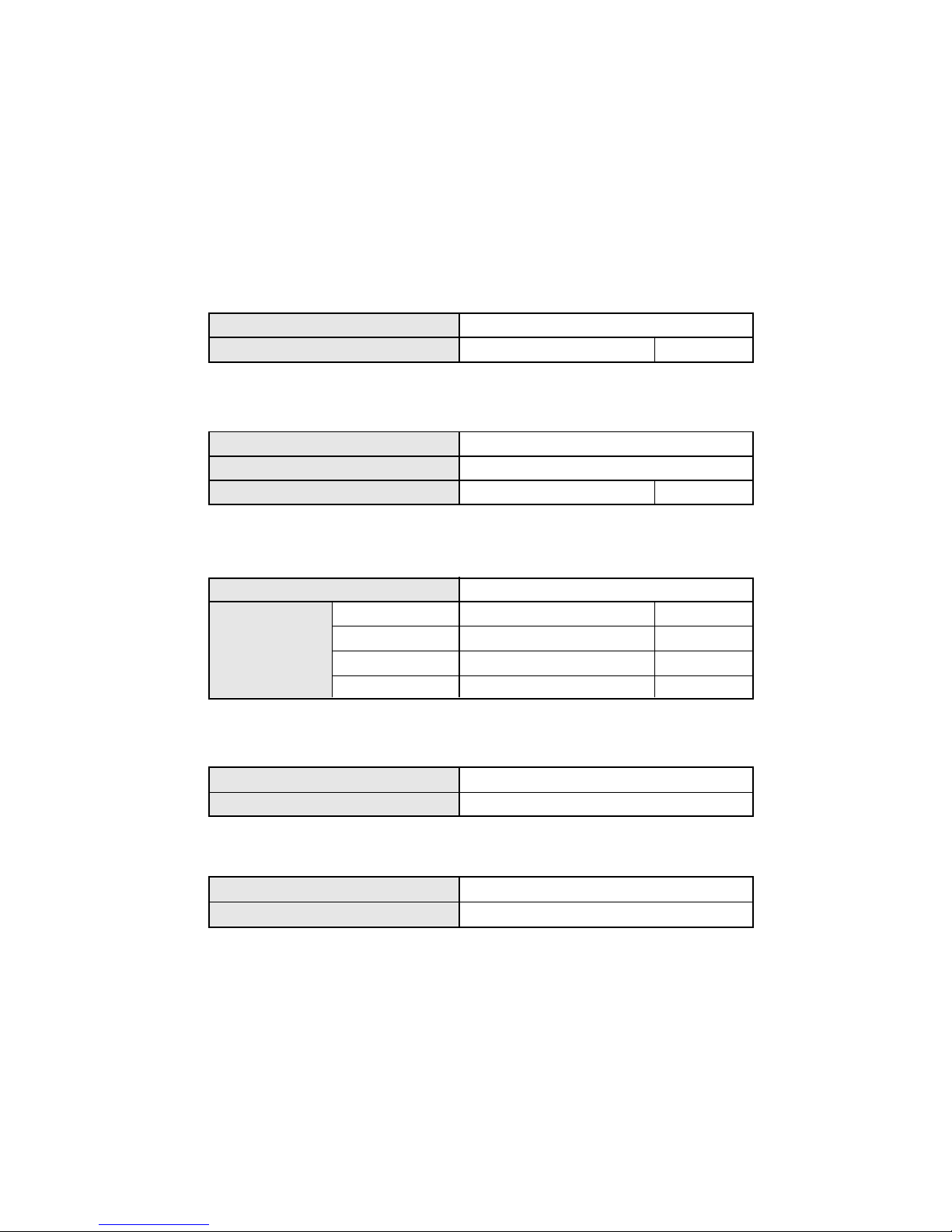
TYPE
MODEL NAME
INDOOR UNIT
POWER SOURCE
(V)
230
FREQUENCY
(Hz)
50
AIR CIRCULATION-Hi
(m3/hr)
ELECTRICAL DATA
FAN MOTOR
DIMENSIONS
POWER SOURCE
(V) 230
DISCRIMINATION
INDOOR UNIT
HI-SPEED
(r.p.m.) 800
MED-SPEED
(r.p.m.)
700
LO-SPEED
(r.p.m.) 600
INDOOR UNIT
235 x 580 x 580 +70
H x W x D
(mm)
H x W x D
(mm)
GRILLE
35 x 650 x 650
WEIGHT
INDOOR UNIT
18 / 23
(kg)
NET / GROSS
NET / GROSS
(kg)
GRILLE
2.2 / 4.3
SPECIFICATIONS
600
COOL & HEAT
AUY18LBAB
MFA-18GTBT
730
670
590
550
MFA-14GTCT
AUY12LBAB , AUY14LBAB
Page 3
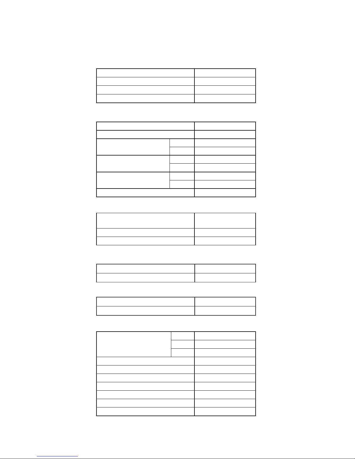
Total Pipe Length
FULL CHARGE AMOUNT
MODEL NAME
COOLING CAPACITY (kW)
HEATING CAPACITY (kW)
POWER SUPPLY (V)
FREQUENCY (Hz)
RUNNING
CURRENT
(A)
INPUT (kW)
EER (kW/kW)
( g )
AIR CIRCULATION - Hi
(m3/hr )
ELECTRICAL SPECIFICATIONS
COMPRESSOR
FAN MOTOR
TYPE
DISCRIMINATION
(220) - 230 - (240)
TNB220FPBM9
REFRIGERANT R410
3,300
COOLIING
HEATING
COOLIING
HEATING
COOLIING
HEATING
TYPE Colling & Heating
AOY30LMAW4
8.0
9.6
9.7
10.5
2.22
2.40
3.60
4.00
50
3,300
Hermetic type, Inverter, 4 poles,
3-phase, DC motor, Twin Rotary
MAX PIPE LENGTH (each unit)
MAX PIPE LENGTH (total)
50.0 m
60.0 m
70.0 m
CHARGELESS
ADDITIONAL CHARGE
3,300 g
3,550 g
3,800 g
REFRIGERANT CHARGE (R410A)
25 g / m
50 m
25 m
MIN. PIPE LENGTH (each unit)
5 m
70 m
MAX ELEVATION (between indoor units)
10 m
MAX ELEVATION (between indoor and outdoor units)
10 m
830 x 900 x 330
68 / 78
OUTDOOR UNIT
(kg)WEIGHT
DIMENSIONS
MFE-60PO
820 / 780
H x W x D (mm)
NET / GROSS
( r.p.m. )HI-SPEED (COOL / HEAT)
DISCRIMINATION
22005.05.23
Page 4
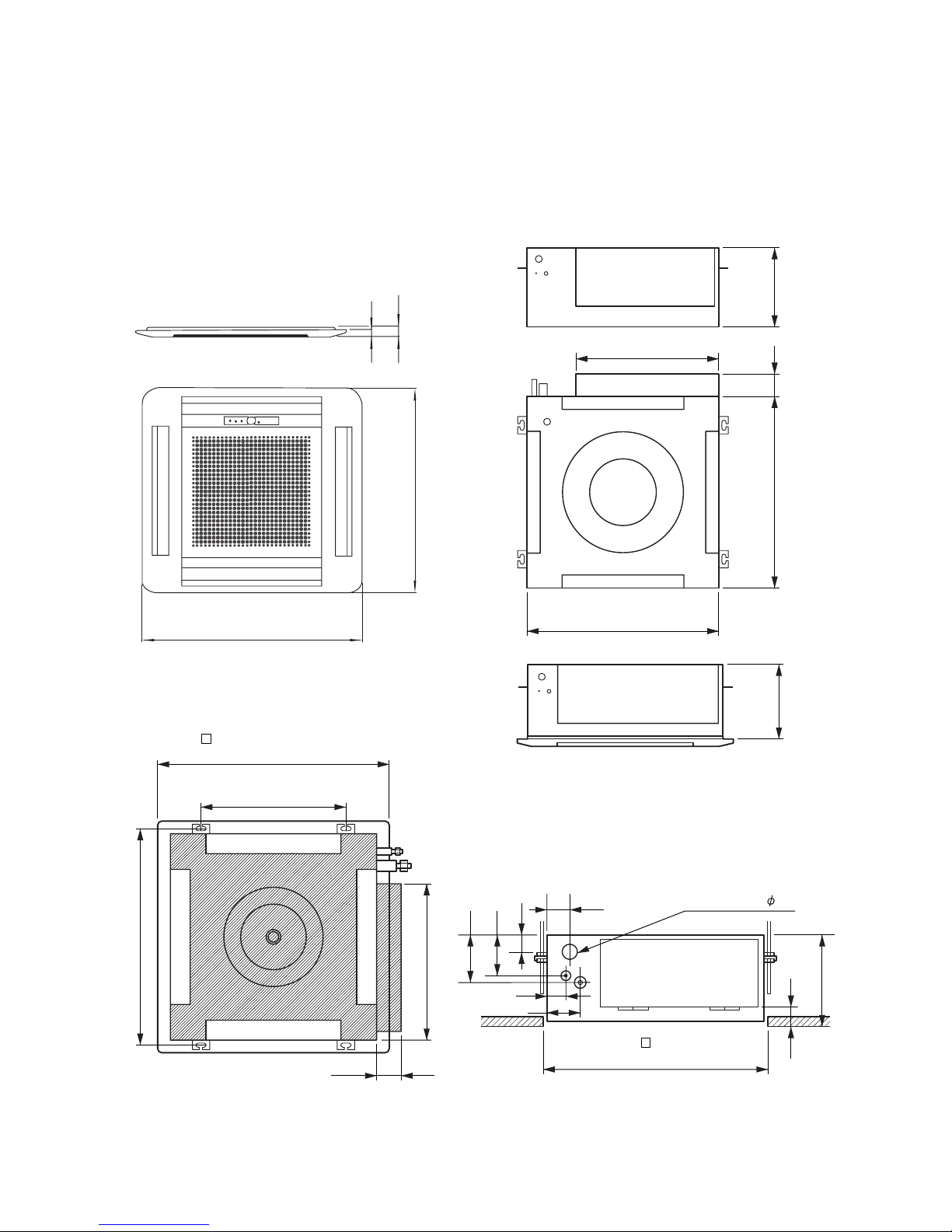
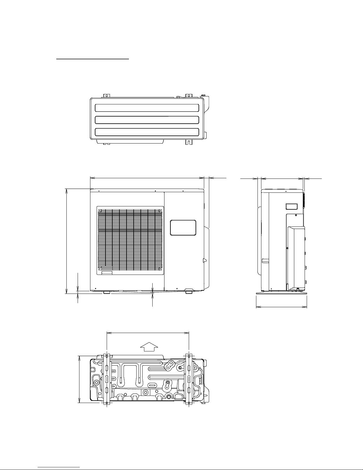
235
66
250
440
580
( 650) (Grille measurement)
650
(Hanging bolt position)
400
(Hanging bolt position)
606
580 66
440
600
(Ceiling opening measurement)
250
60
86
Drain pipe (I.D. 32)
54
46
131
111
47
(unit : mm)
INDOOR UNIT
32005.05.23
OUTLINE AND DIMENSIONS
20
35
650
650
Page 5
(Unit : mm)
OUTDOOR UNIT
Model : AOY30LMAW4
900
21
370
830
9
40 31 330
400
650
Air Flow
12
42005.04.11
Page 6
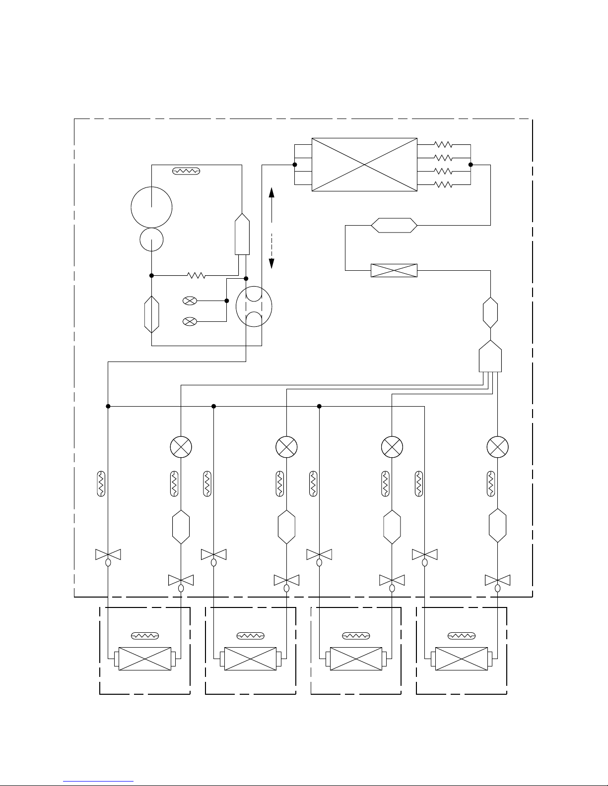
REFRIGERANT SYSTEM DIAGRAM
Outdoor unit
Indoor unit A Indoor unit B Indoor unit C Indoor unit D
52005.04.11
THERMISTOR
THERMISTOR (DIS.TEMP)
OIL BACK
CAPILLARY
CAPILLARY
TUBE
PRESSURE SWITCH(A)
PRESSURE SWITCH(B)
OIL SEPARATOR
COMPRESSOR
ACCUMULATOR
STRAINER
EXPANSION
VALVE
THERMISTOR
PIPE (A-2WV)
THERMIS
-TOR
PIPE
(A-3WV)
3-WAY
VALVE
2-WAY
VALVE
HEAT EXCHANGER
THERMISTOR
STRAINER
EXPANSION
VALVE
THERMISTOR
PIPE (B-2WV)
THERMIS
-TOR
PIPE
(B-3WV)
THERMIS
-TOR
PIPE
(C-3WV)
THERMIS
-TOR
PIPE
(D-3WV)
3-WAY
VALVE
4-WAY VALVE HEAT COOL
2-WAY
VALVE
HEAT EXCHANGER
THERMISTOR
STRAINER
EXPANSION
VALVE
THERMISTOR
PIPE (C-2WV)
3-WAY
VALVE
2-WAY
VALVE
HEAT EXCHANGER
HEAT EXCHANGER
HEAT EXCHANGER
RECEIVER TANK
THERMISTOR
STRAINER
STRAINER
DISTRIBUTOR
EXPANSION
VALVE
THERMISTOR
PIPE (D-2WV)
3-WAY
VALVE
2-WAY
VALVE
HEAT EXCHANGER
Page 7
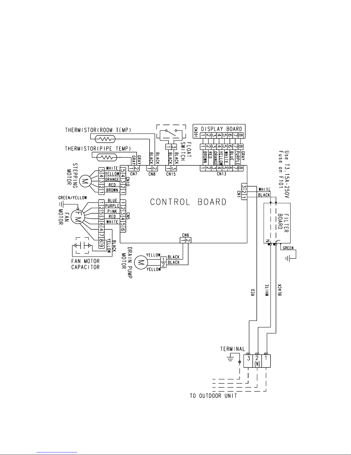
INDOOR UNITS
6
2005.05.06
CIRCUIT DIAGRAM
Page 8
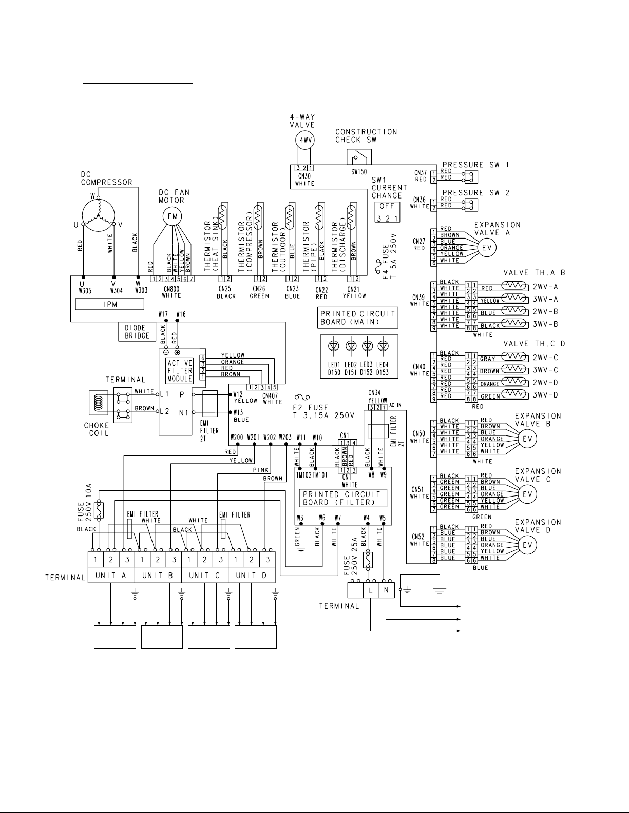
Model : AOY30LMAW4
72005.05.02
INDOOR
UNIT A
INDOOR
UNIT B
INDOOR
UNIT C
INDOOR
UNIT D
TO POWER
SOURCE
Page 9

230 V
50HZ
CONTROLLER PCB ASSY ( MAIN PCB )
INDOOR PCB CIRCUIT DIAGRAM
AUY12LBAB : K01AL-040THSE-C1
AUY14LBAB : K01AL-040WHSE-C1
AUY18LBAB : K01AL-040EHSE-C1
8
2005.03.22
Page 10

CONTROLLER PCB ASSEMBLY
K04AW-0404HUE-C1
POWER SUPPLY PCB
K04BA-0402HUE-P0
W4
W6
W5
W7
W3
B
B
B
B
B
TM101
TM102
W10
B
B
B
B
W16
W17
L1 L2
P+
N1
N2
I O
-
B
W13
B
W12
B
B
B
W305
W304
W303
COMPRESSOR
C. M.
2
3
1 1
3
2
CN407
06 PH / 172520 1007 L480
WHITE
ACTPM CONTROL
1
3
4
5
UL1007 AWG24 BROWN
UL1007 AWG24 ORANGE
UL1007 AWG24 RED
UL1007 AWG24
YELLOW
UL1015 AWG14 x 3
RED
WHITE
BLACK
BLACK
WHITE
RED
UL1015 AWG14 YELLOW
UL1015 AWG14 BLUE
UL1015
AWG14
BROWN
UL1015
AWG14
WHITE
EMI FILTER
TFC25-15-12
2 TURN
1
5
4
3
2
6
UL1015
AWG14
BLACK
UL1015
AWG14
RED
1
3
1
3
4
UL1007 AWG24 RED
UL1007 AWG24 BROWN
UL1007 AWG24 BLACK1
2
3
EMI FILTER
TFC25-15-12
2 TURN
UL1015 AWG14 WHITE
UL1015 AWG20 WHITE
UL1015 AWG20 BLACK
B
B
W9
W8
03 VH / S I N
1015 L250
CN1
B3B-XASK-1-A
WHITE
CT OUT
UL1015 AWG14 BLACK
CN34
B2P3-VH-B-Y
YELLOW
AC I N
CN1
03 XA / 172520 1007 L180
WHITE
CT
CHOKE COIL
L=0.3mH 30A
ACTPM
I C404
SACT32010A
YELLOW
BROWN
WHITE
BLACK
RED
RED
BROWN
BLUE
ORANGE
YELLOW
WHITE
1
2
3
4
5
6
7
1
2
3
4
5
6
1
2
4
5
6
7
1
3
4
5
6
7
1
2
5
6
7
8
1
3
1
2
1
2
1
2
1
2
1
2
1
2
1
2
1
3
4
5
6
7
8
9
1
2
4
5
6
7
8
9
BLACK
WHITE
WHITE
WHITE
WHITE
WHITE
BLACK
GREEN
GREEN
GREEN
GREEN
GREEN
BLACK
BLUE
BLUE
BLUE
BLUE
BLUE
BLACK
BLACK
RED
RED
RED
RED
BROWN
BROWN
BLACK
BLACK
BROWN
BROWN
BLUE
BLUE
BLACK
BLACK
BLACK
BLACK
WHITE
WHITE
WHITE
WHITE
WHITE
WHITE
WHITE
RED
RED
RED
RED
RED
RED
RED
ORANGE
YELLOW
WHITE
BLUE
BROWN
RED
RED
BROWN
BLUE
ORANGE
YELLOW
WHITE
RED
BROWN
BLUE
ORANGE
YELLOW
WHITE
1
2
3
4
5
6
7
8
9
10
1
2
3
4
5
6
7
8
9
10
5V
GND
TAUX
TTXD
TRXD
TMODE
TAUX3
TCK
/ TRES
/ T I CS
5V
GND
TAUX
TTXD
TRXD
TMODE
TAUX3
TCK
/ TRES
/ T I CS
CN602
B10B-PASK-1
WHITE
CN601
B10B-PASK-1
WHITE
SUB-FLASH
MAIN-FLASH
M
M
M
M
F. M.
DC FAN MOTOR
EXPANSION VALVE-A
EXPANSION VALVE-B
EXPANSION VALVE-C
EXPANSION VALVE-D
4-WAY VALVE
PRESURE SWITCH-1
PRESURE SWITCH-2
COMP. TEMPERATURE
HEAT SINK TEMPERATURE
DISCHARGE TEMPERATURE
PIPE TEMPERATURE
OUTDOOR TEMPERATURE
2-WAY VALVE-A TEMP.
3-WAY VALVE-B TEMP.
2-WAY VALVE-B TEMP.
3-WAY VALVE-A TEMP.
RED
YELLOW
BLUE
BLACK
2-WAY VALVE-C TEMP.
3-WAY VALVE-D TEMP.
2-WAY VALVE-D TEMP.
3-WAY VALVE-C TEMP.
GRAY
BROWN
ORANGE
GREEN
CN40
08 XA / 172520 1007
RED
CN39
08 XA / 172520 1007
WHITE
CN23
B2B-XAEK-1-A BLUE
CN22
B2B-XH-AM RED
CN21
B2B-XH-AM YELLOW
CN25
B2B-XAKK-1-A BLACK
CN26
B2B-XAMK-1-A GREEN
CN36
B2B-XASK-1-A WHITE
CN37
B2B-XARK-1-A RED
CN30
179844-1 WHITE
CN52
06 XA / 172520 1007
BLUE
CN51
06 XA / 172520 1007
GREEN
CN50
06 XA / 172520 1007
WHITE
CN27
B6B-XARK-1-A
RED
CN800
B7B-XASK-1-A
WHITE
W200
W203
W202
W201
B
B
B
B
SERIAL-A
SERIAL-D
SERIAL-C
SERIAL-B
3
N
L
3
N
L
3
N
L
3
N
L
N
L
INDOOR UNIT-A
INDOOR UNIT-B
INDOOR UNIT-C
INDOOR UNIT-D
UL1015
AWG20
BROWN
UL1015
AWG20
PINK
UL1015
AWG20
WHITE
EMI FILTER
ZCAT1518-0730
1 TURN
E
UL1015
AWG16
GREEN
UL1015
AWG20
WHITE
UL1015
AWG20
RED
EMI FILTER
ZCAT1518
-0730
1 TURN
UL1015
AWG20
WHITE
UL1015
AWG20
YELLOW
UL1015
AWG20
BLACK
UL1015
AWG20
BLACK
UL1015
AWG20
WHITE
UL1015
AWG20
BLACK
UL1015
AWG20
BLACK
UL1015
AWG20
BLACK
UL1015
AWG14
BLACK
UL1015
AWG14
WHITE
UL1015
AWG14
BLACK
F201
TLC 25A-250V, B
<250V 25A>
F202
FSL 250 10 (EM)
<250V 10A>
AC230V
50Hz
Model : AOY30LMAW4
INVERTER ASSEMBLY
EZ-004HHUE
92005.05.02
OUTDOOR PCB CIRCUIT DIAGRAM
Page 11

12V
5V
I C8
TA7805
1
2
3I O
G
+ +
+
B
B
B
W305
RED
W304
WHITE
W303
BLACK
5V
15V
L300
BL02Rn
R302 1.0K
<1/10W>
C328
2200P
<B>
C327
0.022 <F>
+
C333
47/
35V
C332
0.1
<F>
R370, R371, R373, R374 0.03 <2W> x 4
VN I
VNC
C IN
CFO
FO
UN
VN
WN
P
U
V
W
N
UP
VP I
VUFB
VUFS
VP
VP I
VVFB
VVFS
WP
VP I
VPC
VWFB
VWFS
14
15
16
17
18
19
20
21
22
23
24
25
26
1
2
3
4
5
6
7
8
9
10
11
12
13
2
7
9
16
4
5
12
13
3
6
11
14
1
8
10
15
O1
O2
O3
O4
I 1
I 2
I 3
I 4
COM1
COM2
NC1
NC2
GND3
GND1
GND2
GND4
12V
12V
O1
O2
O3
O4
I 1
I 2
I 3
I 4
COM1
COM2
NC1
NC2
GND3
GND1
GND2
GND4
O1
O2
O3
O4
I 1
I 2
I 3
I 4
COM1
COM2
NC1
NC2
GND3
GND1
GND2
GND4
O1
O2
O3
O4
I 1
I 2
I 3
I 4
COM1
COM2
NC1
NC2
GND3
GND1
GND2
GND4
2
7
9
16
4
5
12
13
2
7
9
16
4
5
12
13
2
7
9
16
4
5
12
13
3
6
11
14
1
8
10
15
3
6
11
14
1
8
10
15
3
6
11
14
1
8
10
15
I C310 PS21867-A
I PM
R33
10K
<1/10W>
R40 1.0K
<1/10W>
C33
0.01
<F>
C311 - C316 1000P <B> x 6
15V
15V
L800
BL02Rn1
C802
0.1 <F>
R801 1.0K <1/2W>
DC FAN1
DTA143EUA
x 2
5V5V
R802
560
<1/4W>
+
C800
100/
16V
<PJ>
D803
DAN217U
1 2
3
2
3
1
2
3
1
C801
0.01
<B>
R804 1.0K
<1/10W>
Q800
Q801
R803
10K
<1/10W>
5V
5V5V
R807
10K
<1/10W>
R808 1.0K
<1/10W>
D804
DAN217U
1 2
3
3
25V1
D61
DAN217U
C29
0.1
<F>
C324 - C326
0.1 <F> x 3
R111
R112
R110
R86
R89
R88
195K <RN - 1/2W>
x 6
1
2
3
4
1
2
3
4
5
6
1
2
3
4
5
6
7
1
2
3
4
5
6
7
1
2
3
4
5
6
7
8
12V
12V
R181 1.5K <1/10W>
R178 1.5K <1/10W>
R179 1.5K <1/10W>
R180 1.5K <1/10W>
12V
R177 1.5K <1/10W>
R176 1.5K <1/10W>
R175 1.5K <1/10W>
R174 1.5K <1/10W>
12V
R173 1.5K <1/10W>
R172 1.5K <1/10W>
R171 1.5K <1/10W>
R170 1.5K <1/10W>
12V
1.5K <1/10W> x 4
R97
R96
R95
R94
12V
I C20
TD62064
I C4 TD62064
I C21
TD62064
I C22
TD62064
E.E.-VALVE
+
+
+
R201
220K
<2W>
C201 - C203 500/450V x 3
+
+ +
C116
0.1 <HCP>
B
B
SMOOTHING CIRCUIT
W12
W13
BLUE
YELLOW
VILTAGE LOCK OUT
5V
5V
15V
R402 2.2K
<1/4W>
+
D402
RD3.3ES
<B2>
1.0K <1/10W> x 6
C321
C322
C323
D301D303 D302
U1JU44 x 3
0.1 <F> x 3
R340
R341
R342
R343
R344
R345
330K
47/35V
<PJ> x 3
<1/10W>
x 3
R362 R363 R361
C303
C304
C305
R360 39
<1/2W>
INVERTER
1
2
3
4
5
6
7
P-AN-CT
P-EPV1-A
P-EPV2-A
P-EPV1-C
P-EPV1-D
P-EPV1-B
P-EPV3-A
P-EPV2-D
P-EPV2-C
P-EPV2-B
P-EPV3-D
P-EPV3-C
P-EPV3-B
P-EPV4-A
P-EPV4-D
P-EPV4-C
P-EPV4-B
ACTPM CONTROL
18V
18V
A
C415
0.01
<F>
Q403
DTA143
3
1
2
1
3
2
R411 22K
<1/10W>
Q401
DTC124EUA
AA
C416
1000P
<B>
P-AFS
5V
A
270 <1/10W>
(1%) x 2
R437
R438
C413
0.01
<F>
A
1
2
3
4
5
1
2
3
4
5
6
7
8
9
10
1
2
3
4
5
6
7
8
9
10
R20
10K
<1/10W>
5V
5V
R611 4.7K
<1/10W>
5V
FLASH-MAIN
FLASH-SUB
R605
22K
<1/10W>
R604
R21
R603
R601
R602
10K <1/10W> x 5
TTXD-2
TRXD-2
TAUX3-2
TCK-2
RSTX-2
TAUX-1
TTXD-1
TRXD-1
TMODE-1
TAUX3-1
TCK-1
RSTX-1
R613
22K
<1/10W>
5V
10K
<1/10W> x 3
R612
R610
R609
5V
CN601
B10B-PASK-1
WHITE
CN602
B10B-PARK
-1 (LF) RED
TAUX
TTXD
TRXD
TMODE
TAUX3
TCK
/ TRES
/ TICS
TAUX
TTXD
TRXD
TMODE
TAUX3
TCK
/ TRES
/ TICS
RSTX-1
5V
R126 - R128
10K <1/10W> x 3
SUB-FWD
SUB-BKWD
TMODE-1
P-SWPRS2
P-SWPRS1
TCK-1
TRXD-1
5V
R73 100K
<1/10W>
R72 1.0K
<1/10W>
C17
0.1
<F>
5V
R158
10K
<1/10W>
R36 1.0K
<1/10W>
C79
0.1
<F>
X1
8.00MHz
<EF0EC>
MICOM-MAIN
I C6
BD4742G
5
4
3
2
1
SUBNCVCC
VOUT
GND
2
1
3
GND
GND
49
24
13
48
19
1
61
62
63
64
20
18
15
14
55
54
53
52
51
50
46
45
12
39
38
37
36
40
26
25
11
56
17
16
2
35
3
59
58
60
21
34
47
27
28
29
30
31
32
33
57
41
42
43
44
10
9
8
7
5
6
4
22
23
AGND
P27
RSTX
P45
P41
P42
P43
P44
MD1
MD0
P61
P60
P35
P34
P33
P32
P31
P30
P25
P24
AVR
P16
P15
P14
P13
P17
P01
P00
AVCC
VCCP63
P62
P46
P12
P50
P37
P36
P40
MD2
P11
P26
P02
P03
P04
P05
P06
P07
P10
C
P20
P21
P22
P23
P57
P56
P55
P54
P52
P53
P51
X0
X1
6
5
4
3
2
1
5V
DSS803
10K <1/10W>
x 2
R16
R17
R34
R35
1.0K
<1/10W>
x 2
C77
C78
0.1 <F> x 2
P-AN-HT
P-CMPTH
SW1
P-AN-TT
P-AN-TA
P-AN-TD
PANT3WV4
PANT2WV4
PANT3WV3
PANT2WV3
PANT2WV2
PANT3WV2
PANT3WV1
PANT2WV1
P-CMPTH
P-AN-HT
P-AN-TD
P-AN-TA
P-AN-TT
P-SWPRS1
P-SWPRS2
I C 1
MB90F462PFM
-G-181-BND-E1
5V
U
X
V
Y
W
Z
+
5V
C20
4.7/50V
<PS>
0.1 <F> x 2
C19
C18
R608 10K <1/10W>
C40 0.1
<F>
P-S I1
P-S I4
P-S I3
P-S I2
SW150
KSM0632B
SUB-CLK
SUB-BKWD
SUB-FWD
P-EPV2-D
P-EPV2-C
P-EPV2-A
P-EPV2-B
P-EPV4-A
P-EPV4-C
P-EPV4-D
P-EPV3-B
P-EPV3-A
P-EPV3-C
P-EPV3-D
5V 5V
R186
R188
R187
22K <1/10W>
x 3
R189 - R190
10K <1/10W> x 2
R196 1.0K <1/10W>
C181
0.1
<F>
MICOM-SUB
R11
R195
10K <1/10W> x 2
7
8
9
10
11
12
51
50
49
48
47
46
45
44
43
42
41
40
52
53
54
55
56
57
58
59
60
61
62
63
1
17
2
16
64
20
19
15
14
39
38
37
36
35
34
33
32
31
30
29
28
27
26
25
24
23
22
18
3
4
5
6
21
13
P83
P82
P81
P80
P71
P70
P67
2
3
1
P66
P65
P64
P63
P62
P61
P60
P53
P52
P51
P50
P43
P42
P41
P40
P37
P36
P35
P34
P33
P32
P31
P30
AVCC
VCC
AVR
MOD
RSTX
PE0
PE1
PE2
PE3
PG0
P00
P01
P02
P03
P04
P05
P06
P07
P10
P11
P12
P13
P14
P20
P21
P22
P23
P24
X0
X1
X1A
X0A
AGND
GND
SUB
NC
VCC
VOUT
GND
1
2
3
4
5
5V
R192 100K
<1/10W>
R193 1.0K
<1/10W>
C179
0.1
<F>
I C153
BD4742G
I C150
MB95F108HSPFM
-G-101-E1
C176
C175
C174
4.7/50V
<PS>
+
5V
0.1 <F> x 2
C35 - C36
0.01 <F> x 2
R407
R403
10K <1/10W> x 2
FH3
PFC5000
-0502
FH4
PFC5000
-0502
F2
T 3.15A
250V
L100
SN-PLATED
DIA 0.6
COMP POSITION DETECT
SW POWER SUPPLY
T1
JPZ-200
+
15V
D100
D1FL20U
16
15
13
12
10
9
1
2
3
6
7
8
+
I O
G
2
1 3
+
C158
0.1
<F>
C159
0.1
<F>
C160
0.1
<F>
C161
0.1
<F>
R150 10K
<1/10W>
R152 10K
<1/10W>
R154 10K
<1/10W>
R156 10K
<1/10W>
5V
R151 14K
<1/10W>
(1%)
R153 14K
<1/10W>
(1%)
R155 14K
<1/10W>
(1%)
R157 14K
<1/10W>
(1%)
L204
BL02Rn1
C46
0.1
<F>
C45
0.1
<F>
C44
0.1
<F>
C43
0.1
<F>
R122 10K
<1/10W>
R120 10K
<1/10W>
R118 10K
<1/10W>
R116 10K
<1/10W>
R123 14K
<1/10W>
(1%)
R121 14K
<1/10W>
(1%)
R119 14K
<1/10W>
(1%)
R117 14K
<1/10W>
(1%)
C24
0.1
<F>
C23
0.1
<F>
C22
0.1
<F>
C21
0.1
<F>
P-FM2POW
FM2FDBK
SUB-CLH
P-POWER
P-AN-CT
P-EPV1-C
P-EPV1-D
P-FM1POW
TTXD-1
TAUX3-1
P-AFS
P-CP-POS
P-S I
P-SO
P-PR
P-LED
P-4WV-AC
P-V2
P-TRIP
P-EPV-A
P-EPV-D
P-EPV-C
P-EPV-B
TAUX-1
P-E2PCS1
P-FM1SEL
FM1FDBK
P-E2PD I1
P-E2PSK1
P-AFDC
P-AFE
P-U
P-X
P-V
P-Y
P-W
P-Z
PANT3WV2
PANT2WV2
PANT3WV1
PANT2WV1
PANT3WV4
PANT2WV4
PANT3WV3
PANT2WV3
P-CP-POS
C95
100P
<CH>
-
-
+
+
7
1
2
3
6
5
4
8
1
2
3
-
+
I C400-2
uPC393
I C400-1
uPC393
C412
0.1
<F>
C414
0.01
<F>
R435
R441
1.0K <1/10W>
x 2
C411
0.01 <F>
DAN217U x 2
D81
D82
15V
I C11-1
uPC393
3 3
2
21 1
R108
2.87K
<1/10W>
(1%)
R105
2.49K
<1/10W>
(1%)
R107
680
<1/10W>
(1%) R87 2.94K
(1%)
<1/10W>
195K <RN - 1/2W>
(1%)
x 2
R106
R104
180K <RN - 1/2W>
(1%)
x 2
R440
R400
R401
2.94K 2.87K
R406
(1%)
<1/10W>
(1%)
<1/10W>
C409
10/25V
<PS>
15V
C87
330P <B>
C89
470P
<B>
C88
0.1
<F>
R103 4.7K
<1/10W>
1
2
3
R114
27K
<1/10W>
R113
1.0K
<1/10W>
Q91
2SC242K
<BQ>
R102
22K
<1/10W>
15V
P-AFDC
P-AFE
P-U
P-V
P-W
P-X
P-Y
P-Z
P-TRIP
P-FM1POW
FM1FDBK
FM2FDBK
CN407
06 PH / 172520
1007 L480
WHITE
ACTPM
CONTROL
I C407 uPC24M18
18V
C406
220/50V
<PJ>
D401
D1FL
20U
C7
220/
35V
R5 10K
<1/10W>
D8
D7
D1FL20U x 2
C4 <PJ>
470/25V
C5 <PJ>
220/16V
C6 <PJ>
100/16V
C418 <PJ>
10/35V
A
R3 100
<1W>
C2 0.047
<ECQB>
R2 1.0K
<RS - 3W>
C1
220P
<BN>
100K <2W> x 2
R6R1
Q1
2SC4236
R140 1.2
<2W>
D1
D1FL20U
3
2
1
D10
RD5.6ES
<B2>
D2
D1FL20U
C3 <PJ>
100/16V
+
R4 330 <1/4W>
P-S I
P-S I1
P-POWER
P-S I2
P-S I3
P-S I4
C167
0.022
<F>
C168
0.022
<F>
C169
0.022
<F>
Q151
2SC2412K <BQ>
Q150
2SC2412K <BQ>
R53
1.0K
<1/10W>
R54 27K
<1/10W>
R160
1.0K
<1/10W>
R164
1.0K
<1/10W>
Q52
2SC2412K <BQ>
R161 27K
<1/10W>
2
2
2
R165 27K
<1/10W>
1
1
1
3
3
3
R167
4.7K
<1/10W>
R163
4.7K
<1/10W>
R58
4.7K
<1/10W>
R166 10K
<1/10W>
R162 10K
<1/10W>
R57 10K
<1/10W>
R50 10K
<1/10W>
5V
5V
5V
1
2
5V
Q51
2SC2412K <BQ>
3
R56 27K
<1/10W>
R55 1.0K
<1/10W>
R51 4.7K
<1/10W>
R52
1.0K
<1/10W>
C51
0.022
<F>
B
B
C115
0.1
<HCP>
W16
RED
W17
BLACK
D101
D25XB60
+
-
1
4
3
2
142
3
181410
5 4 3 2
1
1
2345101418
18
14 10
5 432 1
1234510
14
18
8
7
654 3
2
1
1
2
3
4
5
6
7
8
8
7
6
5 4
3
2
1
1
2345
6
7
8
5V
5V
5V
5V
1
2
3
4
5
6
7
89
10
11
12
13
14
15
16
1B
6B
5B
4B
3B
2B
7B
E
1C
2C
7C
6C
5C
4C
3C
COM
1B
6B
5B
4B
3B
2B
7B
E
1C
2C
7C
6C
5C
4C
3C
COM
1
2
3
4
5
6
7
8
9
10
11
12
13
14
15
16
P-FM1SEL
P-V2
P-4WV-AC
P-LED
P-PR
P-SO1
P-LED1
P-LED4
P-LED3
P-LED2
P-SO4
P-SO3
P-SO2
EEPROM
THERMISTOR
P-E2PCS1
P-E2PSK1
P-E2PDI 1
R206 10K
<1/10W>
PR-SW
12V
5V
C91
0.1
<F>
I C201
BR93L56RF-WE2
I C151
uLN2003A
1
2
3
6
8
4
7
5
VCC
DO
NC
GND
CS
SK
D I
NC
X150
8.00MHz
<EF0EC>
P-EPV4-B
P-EPV1-B
P-EPV1-A
P-SO4
P-SO3
P-SO2
P-POWER
P-SO1
TTXD-2
TRXD-2
TCK-2
P-LED4
P-LED1
P-LED2
P-LED3
RSTX-2
TAUX3-2
C177 0.1
<F>
R194 10K
<1/10W>
I C3
uLN2003A
12V
12V
R185
R182
R183
R184
2.2K
<1/4W>
x 4
D153
D152
D151
D150
SLR-332VR
<RED> x 4
12V
D28
SLR-332VR
<RED>
R43 2.2K
<1/4W>
HY I C 1
HU2001
HY I C 4
HU2001
HY I C 3
HU2001
HY I C 2
HU2001
MAIN CURRENT
SERIAL
4WV
R200 ZPR0RCH400
K101 DW12D1
12V
B
B
B
B
B
B
K17 G5NB-1A
12V
5V
CR5
RE1202
1
2
1
2
1
2
1
2
1
2
1
2
1
2
1
2
1
2
3
4
5
6
7
8
9
1
2
3
4
5
6
7
8
9
1
3
W10
BLACK
W11
WHITE
VA103
470V
<TNR>
F4
T 5A
250V
FH2
FH1
PFC5000
-0502
PFC5000
-0502
4
2
1
3
CN34
B2P3-VH-B-Y
YELLOW
AC VOLT I N
SERIAL-A
W200
RED
SERIAL-B
W201
YELLOW
SERIAL-C
W202
PINK
SERIAL-D
W203
BROWN
CN30
179844-1
WHITE
4-WAY VALVE
CN37
B2B-XARK-1-A
RED
PRESSUR SW1
CN36
B2B-XASK-1-A
WHITE
PRESSUR SW2
COMP. TH.
CN26
B2B-XAMK-1-A
GREEN
HEART SINK
CN25
B2B-XAKK-1-A
BLACK
DISCHARGE TH.
CN21
B2B-XH-AM
YELLOW
PIPE TH.
CN22
B2B-XH-AM
RED
OUTDOOR TH.
CN23
B2B-XAEK-1-A
BLUE
5V
5V
L203
BL02Rn1
R91
R90
2.2K <1/10W>
x 2
1.0K <1/10W>
R93
R92
x 2
L202
BL02Rn1
C71C70
0.1 <F>
x 2
C73
C72
0.01 <F> x 2
L201
BL02Rn1
C60
0.1
<F>
C61
0.1
<F>
C39
0.1
<F>
C38
0.1
<F>
C37
0.1
<F>
R101 10K
<1/10W>
R99 10K
<1/10W>
R62 10K
<1/10W>
R64 10K
<1/10W>
R66 10K
<1/10W>
R100 6.65K
<1/10W>
(1%)
R63 6.65K
<1/10W>
(1%)
R98 1.0K
<1/10W>
(1%)
R65 4.75K
<1/10W>
(1%)
R67 38.3K
<1/10W>
(1%)
CN40
08 XA / 172520
1007 L300
WHITE
2-WAY VALVE-C
3-WAY VALVE-C
2-WAY VALVE-D
3-WAY VALVE-D
CN39
08 XA / 172520
1007 L300
WHITE
2-WAY VALVE-A
3-WAY VALVE-A
2-WAY VALVE-B
3-WAY VALVE-B
CN800
B7B-XASK-1-A
WHITE
DC FAN MOTOR-1
CN1
03 XA / 172520
1007 L180
WHITE
CT
CN27
B6B-XARK-1-A
RED
EXPANSION VALVE-A
CN50
06 XA / 172520
1007 L300
WHITE
EXPANSION
VALVE-B
CN51
06 XA / 172520
1007 L300
WHITE
EXPANSION
VALVE-C
EXPANSION
VALVE-D
CN52
06 XA / 172520
1007 L300
WHITE
R375, R376, R378, R379 0.03 <2W> x 4
C180
0.022
<F>
C53
10K
<1/10W>
CONTROLLER PCB ASSEMBLY
K04AW-0404HUE-C1
Model : AOY30LMAW4
102005.05.02
Page 12

5V
TM101
TM102
B
B
C111
3.3
<LE>
L4
RCH4730-021PF07
C107
3.3
<LE>
TM100
L2
N300300K1D7C
CT1
CT-1B
5V
D60
DAN217U
C64
0.1
<F>
R68 22K
<1/10W>
C65
0.1
<F>
VR1
B2K
+
R61 3.74K
<1/10W>
(1%)
C60
220/16V
<PJ>
R60 1.0K
<1/10W>
(1%)
SA100
RA-302M
C106
3.3
<LE>
C104
0.033
<YE>
C105
0.033
<YE>
C101
3.3
<LE>
VA101
470V
<TNR>
VA102
470V
<TNR>
B
B
B
B
B
B
B
BLACK
WHITE
TO INDOOR UNIT
POWER SOURCE
230V
50Hz
EARTH
AC VOLT OUT
W5
W6
BLACK
WHITE
W7
GREEN
W3
W8
BLACK
WHITE
W9
W4
L1
RCH4730-021PF07
CN1
B3B-XASK-1-A
WHITE
CT OUT
1
2
3
POWER SUPPLY PCB ASSEMBLY
K04BA-0400HUE-P0
Model : AOY30LMAW4
112005.05.02
Page 13

ERROR CONTENTS
TEST RUNNING
When the air conditioner is run by pressing the remote control
unit test run button, the OPERATION and TIMER lamps flash
slowly at the same time.
1. INDOOR UNIT
CHECK ITEMS
Operation can be checked by lighting and flashing of the grille
display section OPERATION and TIMER lamps.
Perform judgment in accordance with the following.
INDOOR UNIT
Error display
OPERATION
lamp
TIMER
lamp
SWING
lamp
Error contents
Indoor unit
Model information abnormal
(permanent type)
Indoor unit
Drain abnormal (permanent type)
Indoor fan abnormal
Room air temperature thermistor
open circuit
Room air temperature thermistor
short circuit
Indoor unit
Piping thermistor open circuit
Indoor unit
Piping thermistor short circuit
Blinks Blinks Goes off
Pulses
4 times
Blinks Goes off
Pulses
6 times
Blinks Goes off
Goes off
Pulses
2 times
Blinks
Blinks
Goes off
Pulses
3 times
Blinks
Blinks
Outdoor unit circuit board error or
miswiring between outdoor unit
and indoor unit
Outdoor unit discharge temperature
sensor error
Outdoor unit piping sensor error
Outdoor unit
outdoor unit temperature sensor
error
Pulses
5 times
Blinks Goes off
Blinks
Pulses
5 times
Goes off
Blinks
Pulses
3 times
Goes off
Goes offBlinks
Pulses
4 times
(1)
Is operation of each button on the remote control unit
normal?
(2)
Does each lamp light normally?
(3)
Do not air flow direction louvers operate normally?
(4)
Is the drain normal?
(5)
Is there any abnormal noise and vibration during operation?
SWING TIMER OPERATION
MANUAL
AUTO
SWING LAMP
(Orange)
TIMER LAMP
(Green)
OPERATION LAMP
(Red)
12
2005.05.24
Page 14

2.OUTDOOR UNIT LEDS
LED A LED B LED C LED D
Communication error (indoor unit A to outdoor unit)
Communication error (indoor unit B to outdoor unit)
Communication error (indoor unit C to outdoor unit)
Communication error (indoor unit D to outdoor unit)
Discharge pipe temperature sensor
Outdoor heat exchanger temperature sensor
Outdoor temperature sensor
Outdoor 2way valve(A) temperature sensor
Outdoor 2way valve(B) temperature sensor
Outdoor 2way valve(C) temperature sensor
Outdoor 2way valve(D) temperature sensor
Outdoor 3way valve(A) temperature sensor
Outdoor 3way valve(B) temperature sensor
Outdoor 3way valve(C) temperature sensor
Outdoor 3way valve(D) temperature sensor
Compressor temperature sensor
Heatsink temperature sensor
Pressure switch A abnormal
Pressure switch B abnormal
Indoor unit connection capacity error
IPM error
Comoressor loter location error
Compressor can not start to operate
Outdoor fan (upper) motor error
Outdoor fan (lower) motor error
Microcomputer error
: Slow flashing - : Off
132005.05.02
1 time
1 time
1 time
1 time
2 times
3 times
4 times
5 times
5 times
5 times
5 times
6 times
6 times
6 times
6 times
7 times
8 times
9 times
10 times
11 times
12 times
13 times
14 times
15 times
16 times
17 times
Page 15

13
2005.05.24
DISASSEMBLY ILLUSTRATION
INDOOR UNITS
Models : AUY12LBAB, AUY14LBAB
411
235
474
462
464
484
495
67
338
465
478
138
146
395
411
479
797
470
127
484
798
835
836
482
196
160
430
234
301
488
457
399
475
469
468
240
743
834
187
467
244
465
287
313
476-3
117-3
476-2
476-1
652-1
184-1
965
964
164
990
411
Page 16

14
2005.10.13
Model : AUY18LBAB
411
464
462
484
495
67
338
465
478
138
146
395
411
479
797
127
484
798
836
482
196
160
430
234
301
488
457
399
475
469
468
240
743
834
187
467
244
465
287
313
476-3
117-3
476-2
476-1
652-1
184-1
965
164
411
474
235
470
835
990
964
Page 17

34
629
514
875
236
815
628
381
628
381
381
223
287
185
989-1
989-2
824-3
381
15
2005.05.06
AUY18LBAB
AUY14LBAB
Models : AUY12LBAB
Page 18

Model : UTG-UDYD-W
417
416
416
392
690
691
694
165
226
692
692
763
705
385
705
690
700
392
692
690
691
777
776
776
758
710
93
690
196
417
691
876-2
711-2
711-1
16
2005.05.06
Page 19

172005.04.05
Model : AOY30LMAW4
Page 20

182005.04.05
Model : AOY30LMAW4
Page 21

192005.05.02
Model : AOY30LMAW4
Page 22

202005.04.05
Model : AOY30LMAW4
Page 23

212005.04.05
Model : AOY30LMAW4
Page 24

34 Capacitor (Fan Motor)
9900284015
67 Rubber
9361279001
117-3 Special Washer M6
313306391007
127 Drain Hose
9359659013
138 Separate Wall-A
9359647003
146 Evaporator Assy-IN
9373214014
160 Drain Pan
9359651000
164 Fan Motor Assy-IN
9601040064
184-1 Thermo. Spring-A
313728262708
185 Rubber Bushing
313005066051
187 Clamp No. 1219
313361271706
196 Clamp SKB-150
313035356905
223 Control Box
9359661016
234 Thermistor Assy-Room
9703299032
235 Thermistor Assy-Pipe
9703297014
236 Controller PCB Assy
9704557933
240 Remote Control Unit
9371190037
244 Pipe Cover
9359646006
287 Cap (Power)
9352173011
301 Clamp NK-2N
313985355201
313 Hooking Wire
9359983002
338 Motor Fixture
9359656005
381 Locking Spacer
313209391506
395 Supporter (Eva. )
9373179016
399 Air Duct
9359660002
411
9359655008
430 Clamp NK-7N
313095365602
457 Drain Pan Support
9359652007
462 Top Cover Plate
9359642015
464
9359643005
465
9359645009
467 Drain Port
313005415658
468 Special Nut-A (Large)
313005446653
469 Special Nut-B (Small)
313005446759
470 Separate Wall-B
9359648000
474 Turbo Fan
9359658009
475 Turbo Fan Rubber
9366013006
476-1 Special Nut M8
313005360755
476-2 Special Washer
301801185049
476-3 Special Washer
9359954002
478 Sensor M. Bracket
9359654001
479 Float Switch
313005416154
482 Pump Unit
9359974000
484 Hanger Metal
9359644002
488 Drain Pan Plug
9359653004
495 Clamp No. 2U46
9352715006
514 Control Box Cover
9359662006
628 Locking Spacer-B
313005446558
629 EMI Filter
0400197119
652-1 Therm. Holder Pipe
313806262805
743 Remote Control Holder Case
9305642014
797 Separate Wall-C
9359649007
798 Pump Hook Bracket
9359650003
815 Terminal-3P
9900203016
824-3 Fuse
0600222512
834 Wire Cover
9359878001
835 Cushion-A (For Pump)
9352211003
836 Cushion-B (For Pump)
9356084016
875 Filter PCB Assy
9704561213
964 Flare Nut-1/2
-----
965 Flare Nut-B
9351062019
989-1 Cord Clamp-A
9359822011
989-2 Cord Clamp-B
9359823018
990 Distributor Assy
9373034049
9900284015
9361279001
313306391007
9359659013
9359647003
9373214014
9359651000
9601040064
313728262708
313005066051
313361271706
313035356905
9359661016
9703299032
9703297014
9704557940
9371190037
9359646006
9352173011
313985355201
9359983002
9359656005
313209391506
9373179016
9359660002
9359655008
313095365602
9359652007
9359642015
9359643005
9359645009
313005415658
313005446653
313005446759
9359648000
9359658009
9366013006
313005360755
301801185049
9359954002
9359654001
313005416154
9359974000
9359644002
9359653004
9352715006
9359662006
313005446558
0400197119
313806262805
9305642014
9359649007
9359650003
9900203016
0600222512
9359878001
9352211003
9356084016
9704561213
9373267010
9351062019
9359822011
9359823018
9373034049
When you order parts, please make a photocopy of this page
and fill the number of the parts in the "Order" column.
INDOOR UNIT
Ref.
No.
Description
AUY12LBAB AUY14LBAB
Ord.
Q'ty
Part No.
22
2005.10.13
PARTS LIST
Supporter-A
Body-A
Body-B
Page 25

34 Capacitor (Fan Motor)
9900270179
67 Rubber
9361279001
117-3 Special Washer M6
313306391007
127 Drain Hose
9359659013
138 Separate Wall-A
9359647003
146 Evaporator Assy-IN
9373214014
160 Drain Pan
9359651000
164 Fan Motor Assy-IN
9601040057
184-1 Thermo. Spring-A
313728262708
185 Rubber Bushing
313005066051
187 Clamp No. 1219
313361271706
196 Clamp SKB-150
313035356905
223 Control Box
9359661016
234 Thermistor Assy-Room
9703299032
235 Thermistor Assy-Pipe
9703297014
236 Controller PCB Assy
9704557797
240 Remote Control Unit
9371190037
244 Pipe Cover
9359646006
287 Cap (Power)
9352173011
301 Clamp NK-2N
313985355201
313 Hooking Wire
9359983002
338 Motor Fixture
9359656005
381 Locking Spacer
313209391506
395 Supporter (Eva. )
9373179016
399 Air Duct
9359660002
411 Supporter-A
9359655008
430 Clamp NK-7N
313095365602
457 Drain Pan Support
9359652007
462 Top Cover Plate
9359642015
464 Body-A
9359643005
When you order parts, please make a photocopy of this page
and fill the number of the parts in the "Order" column.
INDOOR UNIT
465 Body-B
9359645009
467 Drain Port
313005415658
468 Special Nut-A (Large)
313005446653
469 Special Nut-B (Small)
313005446759
470 Separate Wall-B
9359648000
474 Turbo Fan
9359658009
475 Turbo Fan Rubber
9366013006
476-1 Special Nut M8
313005360755
476-2 Special Washer
301801185049
476-3 Special Washer
9359954002
478 Sensor M. Bracket
9359654001
479 Float Switch
313005416154
482 Pump Unit
9359974000
484 Hanger Metal
9359644002
488 Drain Pan Plug
9359653004
495 Clamp No. 2U46
9352715006
514 Control Box Cover
9359662006
628 Locking Spacer-B
313005446558
629 EMI Filter
0400197119
652-1 Therm. Holder Pipe
313806262805
743
Remote Control Holder Case
9305642014
797 Separate Wall-C
9359649007
798 Pump Hook Bracket
9359650003
815 Terminal-3P
9900203016
824-3 Fuse
0600222512
834 Wire Cover
9359878001
835 Cushion-A (for Pump)
9352211003
836 Cushion-B (for Pump)
9356084016
875 Filter PCB Assy
9704561213
965 Flare Nut-B
9351062019
964 Flare Nut-1/2
9373267010
989-1 Cord Clamp-A
9359822011
990 Distributor Assy
9373034117
989-2 Cord Clamp-B
9359823018
Ref.
No.
Description
AUY18LBAB
Ord.
Q'ty
Part No.
Ref.
No.
Description
AUY18LBAB
Ord.
Q'ty
Part No.
23
2005.10.13
Ref.
No.
Description
Ord.
Q'ty
93 Filter 9359632009
165 Motor Cover 9359623014
196 Clamp SKB-150 313035356905
226 Motor Gear 9359629009
385 Indicator PCB Assy 9702224011
9359622017392 Cover-A
416 Insulation (Panel)-A 9359620006
417 Insulation (Panel)-B 9359621003
9359626008
9359627005
690 Joint-A
691 Joint-B
692 Joint Shaft 9359625001
694 Cam Gear 9359628002
9359619017700 Panel
705 Louver 9359624011
710 Intake Grille 9370126006
711-1 Filter Clamp-A 9359634003
711-2 Filter Clamp-B 9359635000
763 Receiver Cover 9359630005
776 Grille Stopper 9359633013
777 Grille Hook 9359761006
876-2 Step Motor-V 9360307019
758 Decoration Plate-A
(UTG-UDYD-W)
9360039019
Part No.
GRILLE ASSY (UTG-UDYD-W)
Ref.
No.
Description
Ord.
Q'ty
Part No.
Page 26

1 Top Panel Sub Assy
2 Front Panel M
3 Fan Guard
4 Grip Side
5 Service Panel M
6 Right Panel M
7 Valve Cover Sub Assy
8 Grip Service
9 Grip
10 Motor Bracket Sub Assy
11 Propeller Fan Assy
12 Motor. DC Brushless
13 Condenser A Assy
14 Separate Wall Assy S
15 Base Assy
16 Inverter Assy
17 Coil. Choke
18 Cap Foot
19 Compressor Sub Assy
20 4-Way Valve Assy
21
Inlet Pipe (Cond) A Assy
22
Outlet Pipe (Cond) A Assy
23 Pressure Switch A Assy
24 Pressure Switch B Assy
25
Accumulator Sub Assy
26 Receiver Tank Sub Assy
27 Valve Plate A Assy
28 Expansion Valve Assy
29 Capillary Assy
30313-Way Valve Assy (1/2")
32 2-Way Valve Assy
33
Coil (Expansion Valve)(A=Red)
34 Coil (Expansion Valve)(B=White)
35 Coil (Expansion Valve)(C=Green)
36 Coil (Expansion Valve)(D=Blue)
37 Rubber Seat (For Comp)
38
Gasket
3940Holder
9374417025
9374094066
9374330010
9374173013
9374093069
9374599028
9374827015
9374171019
9374172016
9374418053
9366378020
9601882015
9374433056
9374629022
9374166084
9705824010
9703458019
9374345014
9374423064
9374425044
9373461067
9374266067
9367726028
9367727025
9374426072
9373426028
9374628025
9370947106
9372197370
3-Way Valve Assy (3/8")
9372205044
9372205051
9372204054
9900057084
9900057053
9900057060
9900057077
9358080009
9370290004
9372066010
Terminal Cover (Comp) 9370289008
Ref.
No.
Ord.
Q'ty
Description
Part No.
AOY30LMAW4 AOY30LMAW4
OUTDOOR UNIT
41 Washer (Rubber)
42 Frange Nut
43 Inverter Box A
44 Inverter Box B Assy
45 Inverter Box C
46 Inverter Box Duct
47 Inverter Box Cover
48 Heat Sink A
49 Inverter Box D
50 Clamp (Cord) C
51 Clamp (Cord)
52 Terminal (3P)
53 Terminal (12P)
54 Fuse Holder (Big)
55 Fuse Holder (Small)
56 Fuse (Big)
57 Fuse (Small)
58 Terminal
59 ACTPM
60 PWB Assy (Power Supply)
9358078006
9358079003
9374603015
9374625017
9374605019
9374609017
9374608010
9374607013
9374606016
9359677000
9356857009
9900203016
9358660164
0501454012
0501456016
0600086039
0600376116
9701971015
9703457012
9705647039
61
PWB Assy (Controller)
62
Holder (Thermo)
63 Heat Sink Thermistor
64 Compressor Temp Thermistor
65
Thermistor (Outdoor Temp)
66 Heat Exchanger Thermistor
67 Discharg Temp Thermistor
68 Wire (Pressure Sw)(Red)
69 Wire (Pressure Sw)(White)
7071Solenoid
72 Thermistor (Pipe)(Red)
9705642058
9372797013
9900311018
9900156022
9703516078
9704220059
9704219114
9367595037
9367595044
Thermistor (Pipe)(White)
9900322014
9900165055
9900289010
Ref.
No.
Ord.
Q'ty
Description
Part No.
When you order parts, please make a photocopy of this page
and fill the number of the parts in the "Order" column.
242005.05.02
Page 27

25
2005.05.24
Application
Name and Shape
Application Part No.
Part No.
9350716029
9352766015
313005446653
313005446759
9371190037
9360256003
0600185534
9305642014
301141533125
INDOOR UNIT ACCESSORIES
Name and Shape
0700139116
301801155020
9360047007
GRILLE ASSY ACCESSORIES
Coupler heat insulation For indoor side
pipe joint
Special nut A
(large flange)
For installing
indoor unit
Special nut B
(small flange)
For installing
indoor unit
Remote control unit Use for air conditioner
operation
Battery
(penlight)
For remote control unit
Remote control unit holder For mounting the remote
control unit
Tapping screw For remote control unit
holder installation
Bolt For opening the
refrigerant valve on the
outdoor unit
Washer For mounting grille
Blower cover insulation For discharged air
Template For ceiling hole cutting
STANDARD ACCESSORIES
( 3 x 12)
OUTDOOR UNIT ACCESSORIES
Application
For outdoor unit drain
piping work (May not be
supplied, depending on
the model.)
For filling in a gap at the
entrance of connection
cords.
Q’ty
1
1
2
Name and Shape
Drain pipe
Drain cap
Putty
ApplicationQ’ty
1
2
1
Name and Shape
For connecting a pipe
with different diameter
to the outdoor unit.
Adapter E (1/4" 3/8")
6.35mm 9.52mm
Adapter G (1/2" 5/8")
12.7mm 15.88mm
Adapter D (1/2" 3/8")
12.7mm 9.52mm
Page 28

0504G2815
 Loading...