

Fujitsu AUXG-KVLA Series Installation Manual
AIR CONDITIONER
Compact cassette type
INSTALLATION MANUAL
PART No. 9379124119-03
[Original instructions] For authorized service personnel only.
Contents
1. SAFETY PRECAUTIONS ...................................................................... 1
1.1. Precautions for using R32 refrigerant ............................................. 2
2. PRODUCT SPECIFICATION ................................................................ 4
2.1. Installation tools .............................................................................. 4
2.2. Accessories .................................................................................... 4
2.3. Cassette grille accessories ............................................................. 4
2.4. Pipe requirement ............................................................................5
2.5. Electrical requirement ..................................................................... 5
2.6. Optional parts .................................................................................5
3. INSTALLATION WORK ......................................................................... 5
3.1. Selecting an installation location .................................................... 5
3.2. Installation dimensions ...................................................................5
3.3. Installing the unit ............................................................................. 6
3.4. Drain installation ............................................................................. 6
3.5. Pipe installation .............................................................................. 7
3.6. Electrical wiring ............................................................................... 8
3.7. Remote controller setting ...............................................................11
4. CASSETTE GRILLE INSTALLATION ...................................................11
4.1. Remove the intake grille ................................................................11
4.2. Installing the panel to indoor unit ...................................................11
4.3. Attach the intake grille ..................................................................12
5. OPTIONAL INSTALLATION WORK .................................................... 12
5.1. Optional kit installation .................................................................. 12
5.2. External input and output .............................................................. 12
5.3. Remote sensor (Optional parts) ................................................... 13
5.4. Other optional parts ...................................................................... 13
5.5. Optional parts cable binding ......................................................... 13
6. REMOTE CONTROL INSTALLATION .................................................14
6.1. Group control ................................................................................ 14
6.2. Multiple remote control .................................................................15
6.3. Simultaneous multi-system operation ........................................... 15
7. FUNCTION SETTING ......................................................................... 16
7.1. Function details ............................................................................ 16
8. CHECK LIST ....................................................................................... 18
9. TEST RUN ........................................................................................... 18
9.1. Check items .................................................................................. 18
9.2. Operation method ......................................................................... 18
10. FINISHING ........................................................................................ 18
10.1. Installing heat insulation .............................................................18
11. CUSTOMER GUIDANCE .................................................................. 18
12. ERROR CODES ................................................................................ 18
NOTES: This manual describes how to install the air conditioner described above.
Handling and installation shall only be done by professionals as outlined in this
manual.
1. SAFETY PRECAUTIONS
• Be sure to read this manual thoroughly before installation.
• The warnings and precautions indicated in this manual contain important information
pertaining to your safety. Be sure to observe them.
• Hand this manual, together with the operating manual, to the customer. Request the
customer to keep them on hand for future use, such as for relocating or repairing the unit.
WARNING
Indicates a potentially or imminently hazardous situation
which, if not avoided, could result in death or serious injury.
CAUTION
Indicates a potentially hazardous situation that may result in
minor or moderate injury or damage to property.
WARNING
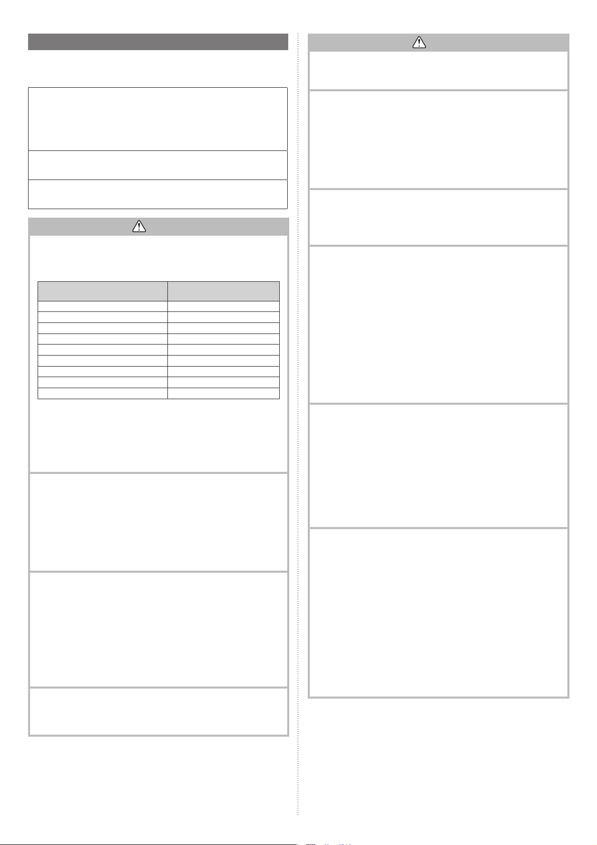
• The appliance shall be installed, operated and stored in a room with a fl oor area larger
2
than X m
Amount of refrigerant charge
M (kg)
M ≤ 1.22 -
1.22 < M ≤ 1.23
1.23 < M ≤ 1.50 2.15
1.50 < M ≤ 1.75 2.92
1.75 < M ≤ 2.0 3.82
2.0 < M ≤ 2.5 5.96
2.5 < M ≤ 3.0 8.59
3.0 < M ≤ 3.5 11.68
3.5 < M ≤ 4.0 15.26
(IEC 60335-2-40)
• Installation of this product must be done by experienced service technicians or professional installers only in accordance with this manual. Installation by non-professional
or improper installation of the product might cause serious accidents such as injury,
water leakage, electric shock, or fi re. If the product is installed in disregard of the
instructions in this manual, it will void the manufacturer’s warranty.
• Do not turn on the power until all work has been completed. Turning on the power before the work is completed can cause serious accidents such as electric shock or fi re.
• If refrigerant leaks when you are working, ventilate the area. If the leaking refrigerant
is exposed to a direct fl ame, it may produce a toxic gas.
• Installation must be performed in accordance with regulations, codes, or standards for
electrical wiring and equipment in each country, region, or the installation place.
• Do not use means to accelerate the defrosting process or to clean, other than those
recommended by the manufacturer.
• This appliance is not intended for use by persons (including children) with reduced
physical, sensory or mental capabilities, or lack of experience and knowledge, unless
they have been given supervision or instruction concerning use of the appliance by a
person responsible for their safety. Children should be supervised to ensure that they
do not play with the appliance.
• To avoid danger of suffocation, keep the plastic bag or thin fi lm used as the packaging
material away from young children.
• The appliance shall be stored in a room without continuously operating ignition
sources (for example: open fl ames, an operating gas appliance or an operating
electric heater).
• Do not pierce or burn.
• Be aware that refrigerants may not contain an odour.
Minimum room area
X (m
1.45
2
)
CAUTION
• Read carefully all safety information written in this manual before you install or use the
air conditioner.
• Install the product by following local codes and regulations in force at the place of
installation, and the instructions provided by the manufacturer.
• This product is part of a set constituting an air conditioner. The product must not be
installed alone or be installed with a device not authorized by the manufacturer.
• Always use a separate power supply line protected by a circuit breaker operating on
all wires with a distance between contact of 3 mm for this product.
• To protect the persons, earth (ground) the product correctly, and use the power cable
combined with an Earth Leakage Circuit Breaker (ELCB).
• This product is not explosion proof, and therefore should not be installed in an explosive atmosphere.
• To avoid getting an electric shock, never touch the electrical components soon after
the power supply has been turned off. After turning off the power, always wait 5 minutes or more before you touch the electrical components.
• This product contains no user-serviceable parts. Always consult experienced service
technicians for repairing.
• When moving or relocating the air conditioner, consult experienced service technicians
for disconnection and reinstallation of the product.
• Do not touch the aluminum fi ns of heat exchanger built-in the indoor or outdoor unit to
avoid personal injury when you install or maintain the unit.
• Do not place any other electrical products or household belongings under the product.
Condensation dripping from the product might get them wet, and may cause damage
or malfunction to the property.
• Be careful not to scratch the air conditioner when handling it.
EnglishDeutschFrançaisEspañolItalianoEλληvIkάPortuguêsРусский
Türkçe
Türkçe
En-1
1.1. Precautions for using R32 refrigerant
The basic installation work procedures are the same as conventional refrigerant (R410A,
R22) models.
However, pay careful attention to the following points:
Since the working pressure is 1.6 times higher than that of refrigerant R22 models,
some of the piping and installation and service tools are special. (Refer to “2.1. Installation tools”.)
Especially, when replacing a refrigerant R22 model with a new refrigerant R32 model,
always replace the conventional piping and flare nuts with the R32 and R410A piping and
fl are nuts on the outdoor unit side.
For R32 and R410A, the same fl are nut on the outdoor unit side and pipe can be used.
Models that use refrigerant R32 and R410A have a different charging port thread diameter to prevent erroneous charging with refrigerant R22 and for safety. Therefore, check
beforehand. [The charging port thread diameter for R32 and R410A is 1/2-20 UNF.]
Be more careful than R22 so that foreign matter (oil, water, etc.) does not enter the
piping. Also, when storing the piping ,securely seal the opening by pinching, taping, etc.
(Handling of R32 is similar to R410A.)
CAUTION
1-Installation (Space)
• That the installation of pipe-work shall be kept to a minimum.
• That pipe-work shall be protected from physical damage.
• The appliance shall not be installed in an unventilated space, if that space is smaller
(IEC 60335-2-40)
• That compliance with national gas regulations shall be observed.
• That mechanical connections shall be accessible for maintenance purposes.
• In cases that require mechanical ventilation, ventilation openings shall be kept clear
• When disposing of the product is used, be based on national regulations, properly
2-Servicing
2-1 Service personnel
• Any person who is involved with working on or breaking into a refrigerant circuit
• Servicing shall only be performed as recommended by the equipment manufacturer.
• Servicing shall be performed only as recommended by the manufacturer.
2-2 Work
• Prior to beginning work on systems containing fl ammable refrigerants, safety checks
• Work shall be undertaken under a controlled procedure so as to minimize the risk of
• All maintenance staff and others working in the local area shall be instructed on the
• Work in confi ned spaces shall be avoided.
• The area around the workspace shall be sectioned off.
• Ensure that the conditions within the area have been made safe by control of fl am-
2-3 Checking for presence of refrigerant
• The area shall be checked with an appropriate refrigerant detector prior to and during
• Ensure that the leak detection equipment being used is suitable for use with fl am-
2
than X m
Amount of refrigerant charge
M (kg)
M ≤ 1.22 -
1.22 < M ≤ 1.23
1.23 < M ≤ 1.50 2.15
1.50 < M ≤ 1.75 2.92
1.75 < M ≤ 2.0 3.82
2.0 < M ≤ 2.5 5.96
2.5 < M ≤ 3.0 8.59
3.0 < M ≤ 3.5 11.68
3.5 < M ≤ 4.0 15.26
of obstruction.
processed.
should hold a current valid certifi cate from an industry-accredited assessment
authority, which authorises their competence to handle refrigerants safely in accordance with an industry recognised assessment specifi cation.
Maintenance and repair requiring the assistance of other skilled personnel shall be
carried out under the supervision of the person competent in the use of fl ammable
refrigerants.
are necessary to ensure that the risk of ignition is minimized. For repair to the refrigerating system, the precautions in 2-2 to 2-8 shall be complied with prior to conducting work on the system.
a fl ammable gas or vapour being present while the work is being performed.
nature of work being carried out.
mable material.
work, to ensure the technician is aware of potentially fl ammable atmospheres.
mable refrigerants, i.e. nonsparking, adequately sealed or intrinsically safe.
Minimum room area
X (m
1.45
2
)
CAUTION
2-4 Presence of fi re extinguisher
• If any hot work is to be conducted on the refrigeration equipment or any associated
parts, appropriate fi re extinguishing equipment shall be available at hand.
• Have a dry powder or CO
2-5 No ignition sources
• No person carrying out work in relation to a refrigeration system which involves
exposing any pipe work that contains or has contained fl ammable refrigerant shall
use any sources of ignition in such a manner that it may lead to the risk of fi re or
explosion.
• All possible ignition sources, including cigarette smoking, should be kept suffi ciently
far away from the site of installation, repairing, removing and disposal, during which
fl ammable refrigerant can possibly be released to the surrounding space.
• Prior to work taking place, the area around the equipment is to be surveyed to make
sure that there are no fl ammable hazards or ignition risks. “No Smoking” signs shall
be displayed.
2-6 Ventilated area
• Ensure that the area is in the open or that it is adequately ventilated before breaking
into the system or conducting any hot work.
• A degree of ventilation shall continue during the period that the work is carried out.
• The ventilation should safely disperse any released refrigerant and preferably expel
it externally into the atmosphere.
2-7 Checks to the refrigeration equipment
• Where electrical components are being changed, they shall be fi t for the purpose
and to the correct specifi cation.
• At all times the manufacturer’s maintenance and service guidelines shall be followed.
• If in doubt consult the manufacturer’s technical department for assistance.
• The following checks shall be applied to installations using fl ammable refrigerants.
- The charge size is in accordance with the room size within which the refrigerant
containing parts are installed.
- The ventilation machinery and outlets are operating adequately and are not
obstructed.
- If an indirect refrigerating circuit is being used, the secondary circuit shall be
checked for the presence of refrigerant.
- Marking to the equipment continues to be visible and legible. Markings and signs
that are illegible shall be corrected.
- Refrigeration pipe or components are installed in a position where they are unlikely
to be exposed to any substance which may corrode refrigerant containing components, unless the components are constructed of materials which are inherently
resistant to being corroded or are suitably protected against being so corroded.
2-8 Checks to electrical devices
• Repair and maintenance to electrical components shall include initial safety checks
and component inspection procedures.
• If a fault exists that could compromise safety, then no electrical supply shall be connected to the circuit until it is satisfactorily dealt with.
• If the fault cannot be corrected immediately but it is necessary to continue operation,
an adequate temporary solution shall be used.
• This shall be reported to the owner of the equipment so all parties are advised.
• Initial safety checks shall include.
- That capacitors are discharged: this shall be done in a safe manner to avoid possibility of sparking.
- That there no live electrical components and wiring are exposed while charging,
recovering or purging the system.
- That there is continuity of earth bonding.
3-Repairs to sealed components
• During repairs to sealed components, all electrical supplies shall be disconnected
from the equipment being worked upon prior to any removal of sealed covers, etc.
• If it is absolutely necessary to have an electrical supply to equipment during servicing, then a permanently operating form of leak detection shall be located at the most
critical point to warn of a potentially hazardous situation.
• Particular attention shall be paid to the following to ensure that by working on electrical components, the casing is not altered in such a way that the level of protection is
affected.
• This shall include damage to cables, excessive number of connections, terminals not
made to original specifi cation, damage to seals, incorrect fi tting of glands, etc.
• Ensure that apparatus is mounted securely.
• Ensure that seals or sealing materials have not degraded such that they no longer
serve the purpose of preventing the ingress of fl ammable atmospheres.
• Replacement parts shall be in accordance with the manufacturer’s specifi cations.
NOTES: The use of silicon sealant may inhibit the effectiveness of some types of leak
detection equipment.
Intrinsically safe components do not have to be isolated prior to working on
them.
fi re extinguisher adjacent to the charging area.
2
En-2

CAUTION
4-Repair to intrinsically safe components
• Do not apply any permanent inductive or capacitance loads to the circuit without
ensuring that this will not exceed the permissible voltage and current permitted for
the equipment in use.
• Intrinsically safe components are the only types that can be worked on while live in
the presence of a fl ammable atmosphere.
• The test apparatus shall be at the correct rating.
• Replace components only with parts specifi ed by the manufacturer.
• Other parts may result in the ignition of refrigerant in the atmosphere from a leak.
5-Cabling
• Check that cabling will not be subject to wear, corrosion, excessive pressure, vibration, sharp edges or any other adverse environmental effects.
• The check shall also take into account the effects of aging or continual vibration from
sources such as compressors or fans.
6-Detection of fl ammable refrigerants
• Under no circumstances shall potential sources of ignition be used in the searching
for or detection of refrigerant leaks.
• A halide torch (or any other detector using a naked fl ame) shall not be used.
7-Leak detection methods
• Electronic leak detectors shall be used to detect fl ammable refrigerants, but the
sensitivity may not be adequate, or may need re-calibration. (Detection equipment
shall be calibrated in a refrigerant-free area.)
• Ensure that the detector is not a potential source of ignition and is suitable for the
refrigerant used.
• Leak detection equipment shall be set at a percentage of the LFL of the refrigerant
and shall be calibrated to the refrigerant employed and the appropriate percentage
of gas (25 % maximum) is confi rmed.
• Leak detection fl uids are suitable for use with most refrigerants but the use of
detergents containing chlorine shall be avoided as the chlorine may react with the
refrigerant and corrode the copper pipe-work.
• If a leak is suspected, all naked fl ames shall be removed/extinguished.
• If a leakage of refrigerant is found which requires brazing, all of the refrigerant shall
be recovered from the system, or isolated (by means of shut off valves) in a part of
the system remote from the leak.
Oxygen free nitrogen (OFN) shall then be purged through the system both before
and during the brazing process.
8-Removal and evacuation
• When breaking into the refrigerant circuit to make repairs – or for any other
purpose –conventional procedures shall be used.
However, it is important that best practice is followed since fl ammability is a consid-
eration.
The following procedure shall be adhered to:
• remove refrigerant
• purge the circuit with inert gas
• evacuate
• purge again with inert gas
• open the circuit by cutting or brazing
• The refrigerant charge shall be recovered into the correct recovery cylinders.
• The system shall be “fl ushed” with OFN to render the unit safe.
• This process may need to be repeated several times.
• Compressed air or oxygen shall not be used for this task.
• Flushing shall be achieved by breaking the vacuum in the system with OFN and
continuing to fi ll until the working pressure is achieved, then venting to atmosphere,
and fi nally pulling down to a vacuum.
• This process shall be repeated until no refrigerant is within the system.
• When the fi nal OFN charge is used, the system shall be vented down to atmospheric
pressure to enable work to take place.
• This operation is absolutely vital if brazing operations on the pipe work are to take
place.
• Ensure that the outlet for the vacuum pump is not close to any ignition sources and
there is ventilation available.
9-Charging procedures
• In addition to conventional charging procedures, the following requirements shall be
followed.
- Ensure that contamination of different refrigerants does not occur when using
charging equipment.
Hoses or lines shall be as short as possible to minimize the amount of refrigerant
contained in them.
- Cylinders shall be kept upright.
- Ensure that the refrigeration system is earthed prior to charging the system with
refrigerant.
- Label the system when charging is complete (if not already).
- Extreme care shall be taken not to overfi ll the refrigeration system.
• Prior to recharging the system it shall be pressure tested with OFN.
• The system shall be leak tested on completion of charging but prior to commissioning.
• A follow up leak test shall be carried out prior to leaving the site.
CAUTION
10-Decommissioning
• Before carrying out this procedure, it is essential that the technician is completely
familiar with the equipment and all its details.
• It is recommended good practice that all refrigerants are recovered safely.
• Prior to the task being carried out, an oil and refrigerant sample shall be taken in
case analysis is required prior to re-use of reclaimed refrigerant.
• It is essential that electrical power is available before the task is commenced.
a) Become familiar with the equipment and its operation.
b) Isolate system electrically.
c) Before attempting the procedure ensure that:
• mechanical handling equipment is available, if required, for handling refrigerant cylinders;
• all personal protective equipment is available and being used correctly;
• the recovery process is supervised at all times by a competent person;
• recovery equipment and cylinders conform to the appropriate standards.
d) Pump down refrigerant system, if possible.
e) If a vacuum is not possible, make a manifold so that refrigerant can be removed
from various parts of the system.
f) Make sure that cylinder is situated on the scales before recovery takes place.
g) Start the recovery machine and operate in accordance with manufacturer’s
instructions.
h) Do not overfi ll cylinders. (No more than 80 % volume liquid charge).
i) Do not exceed the maximum working pressure of the cylinder, even temporarily.
j) When the cylinders have been fi lled correctly and the process completed, make
sure that the cylinders and the equipment are removed from site promptly and all
isolation valves on the equipment are closed off.
k) Recovered refrigerant shall not be charged into another refrigeration system un-
less it has been cleaned and checked.
11-Labelling
• Equipment shall be labelled stating that it has been de-commissioned and emptied
of refrigerant.
• The label shall be dated and signed.
• Ensure that there are labels on the equipment stating the equipment contains fl am-
mable refrigerant.
12-Recovery
• When removing refrigerant from a system, either for servicing or decommissioning, it
is recommended good practice that all refrigerants are removed safely.
• When transferring refrigerant into cylinders, ensure that only appropriate refrigerant
recovery cylinders are employed.
• Ensure that the correct number of cylinders for holding the total system charge are
available.
• All cylinders to be used are designated for the recovered refrigerant and labelled for
that refrigerant (i.e. special cylinders for the recovery of refrigerant).
• Cylinders shall be complete with pressure relief valve and associated shut-off valves
in good working order.
• Empty recovery cylinders are evacuated and, if possible, cooled before recovery
occurs.
• The recovery equipment shall be in good working order with a set of instructions
concerning the equipment that is at hand and shall be suitable for the recovery of
fl ammable refrigerants.
• In addition, a set of calibrated weighing scales shall be available and in good working
order.
• Hoses shall be complete with leak-free disconnect couplings and in good condition.
• Before using the recovery machine, check that it is in satisfactory working order, has
been properly maintained and that any associated electrical components are sealed
to prevent ignition in the event of a refrigerant release.
Consult manufacturer if in doubt.
• The recovered refrigerant shall be returned to the refrigerant supplier in the correct
recovery cylinder, and the relevant Waste Transfer Note arranged.
• Do not mix refrigerants in recovery units and especially not in cylinders.
• If compressors or compressor oils are to be removed, ensure that they have been
evacuated to an acceptable level to make certain that fl ammable refrigerant does not
remain within the lubricant.
• The evacuation process shall be carried out prior to returning the compressor to the
suppliers.
• Only electric heating to the compressor body shall be employed to accelerate this
process.
• When oil is drained from a system, it shall be carried out safely.
En-3
Explanation of symbols displayed on the indoor unit or outdoor unit.
This symbol shows that this appliance uses a fl ammable
WARNING
CAUTION
CAUTION
CAUTION
refrigerant.
If the refrigerant is leaked and exposed to an external ignition source, there is a risk of fi re.
This symbol shows that the operation manual should be
read carefully.
This symbol shows that a service personnel should be
handling this equipment with reference to the installation
manual.
This symbol shows that information is available such as
the operating manual or installation manual.
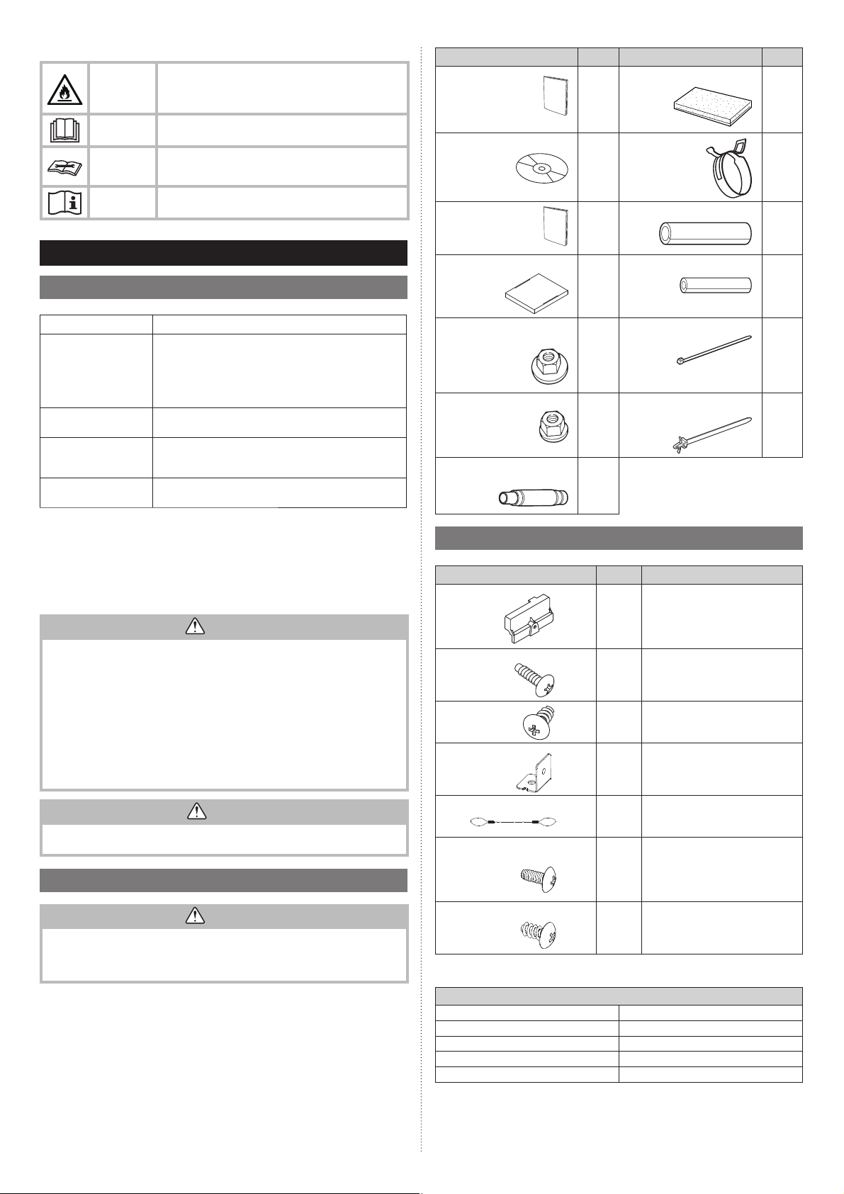
Name and Shape
Operating manual
Operating manual
(CD-ROM)
Installation manual
(This manual)
Q’ty
1
1
1
Name and Shape
Drain hose insulation
Hose band
Coupler heat insulation (large)
Q’ty
1
1
1
2. PRODUCT SPECIFICATION
2.1. Installation tools
Tool name Change from R22 to R32 (R410A)
Pressure is high and cannot be measured with a R22
gauge. To prevent erroneous mixing of other refrigerants,
Gauge manifold
Charge hose
Vacuum pump
Gas leakage detector
■Copper pipes
It is necessary to use seamless copper pipes and it is desirable that the amount of residual
oil is less than 40 mg/10 m. Do not use copper pipes having a collapsed, deformed or
discolored portion (especially on the interior surface). Otherwise, the expansion value or
capillary tube may become blocked with contaminants.
As an air conditioner using R32 (R410A) incurs pressure higher than when using R22, it is
necessary to choose adequate materials.
• Do not use the existing (for R22) piping and fl are nuts.
If the existing materials are used, the pressure inside the refrigerant cycle will rise and
cause failure, injury, etc. (Use the special R32/R410A materials.)
• Use (refi ll or replace with) specifi ed refrigerant (R32) only. Use of unspecifi ed refriger-
ant can cause product malfunction, burst, or injury.
• Do not mix any gas or impurities except specifi ed refrigerant (R32). Infl ow of air or ap-
plication of unspecifi ed material makes the internal pressure of the refrigerant cycle too
high, and may cause product malfunction, burst of piping, or injury.
• For installation purposes, be sure to use the parts supplied by the manufacturer or
other prescribed parts. The use of non-prescribed parts can cause serious accidents
such as the unit falling, water leakage, electric shock, or fi re.
• Do not turn on the power until all work has been completed.
the diameter of each port has been changed.
It is recommended to use gauge with seals -0.1 to 5.3 MPa
(-1 to 53 bar) for high pressure.
-0.1 to 3.8 MPa (-1 to 38 bar) for low pressure.
To increase pressure resistance, the hose material and base
size were changed. (R32/R410A)
A conventional vacuum pump can be used by installing a
vacuum pump adapter.
(Use of a vacuum pump with a series motor is prohibited.)
Special gas leakage detector for HFC refrigerant R410A or
R32.
WARNING
Template
(carton top)
1
Special nut A
(large fl ange)
4
Special nut B
(small fl ange)
Drain hose
[VP25(O.D.32, I.D.25)]
4
1
2.3. Cassette grille accessories
Name and Shape
Connector cover
Tapping screw
(M5 × 12 mm)
Tapping screw
(M4 × 12 mm) 1
L angle
Q’ty Description
Coupler heat insulation (small)
Cable tie (for electrical wiring)
Wire clamper (for electrical wiring)
For covering connector
1
For mounting cassette grille
4
For mounting connector cover
For mounting the hook wire to the
cassette grille
2
1
2
1
CAUTION
This manual describes how to install the indoor unit only. To install the outdoor unit or
branch box, (if any), refer to the installation manual included in each product.
2.2. Accessories
WARNING
For installation purposes, be sure to use the parts supplied by the manufacturer or other
prescribed parts.
The use of non-prescribed parts can cause serious accidents such as the unit to fall,
water leakage, electric shock, or fi re.
• Keep the Installation Manual in a safe place and do not discard any other accessories
until the installation work has been completed.
• The following installation parts are furnished. Use them as required.
En-4
Hook wire
Screw [pitch small]
(M4 × 10 mm)
Screw [pitch large]
(M4 × 10 mm)
The following items are necessary to install this air conditioner. (The items are not included with the air conditioner and must be purchased separately.)
For suspending the cassette grille
2
For mounting the hook wire (for metals)
2
For mounting the L angle and hook
wire (for resins)
4
Additional materials
Connection pipe assembly Wall cap
Connection cable (4-conductor)
Wall pipe Drain hose
Decorative tape Tapping screws
Vinyl tape Putty
Saddle
2.4. Pipe requirement
3.1. Selecting an installation location
Model Gas pipe size (thickness) [mm] Luquid pipe size (thickness) [mm]
07, 09, 12, 14 Ø 9.52 (0.80) Ø 6.35 (0.80)
18, 22, 24 Ø 12.70 (0.80) Ø 6.35 (0.80)
CAUTION
Refer to the installation manual for the outdoor unit for description of allowable pipe
length and height difference.
• Use pipe with water-resistant heat insulation.
CAUTION
• Wrap heat insulation around both gas pipe and liquid pipe.
No heat-insulation work or incorrect heat-insulation work may cause water leaks.
• In a reverse cycle model, use heat insulation with heat resistance above 120 °C.
• If expected humidity of the installation location of refrigerant pipes is higher than
70 %, wrap the heat insulation around the refrigerant pipes.
If the expected humidity is between 70 % and 80 %, use heat insulation that has
a thickness of 15 mm or more.
If the expected humidity is higher than 80 %, use heat insulation that has a thickness
of 20 mm or more.
• The use of thinner heat insulation than specifi ed above, may cause a condensation
on the surface of the insulation.
• Use heat insulation with thermal conductivity of 0.045 W/(
m•K
) or less, at 20 °C.
2.5. Electrical requirement
The indoor unit is powered from the outdoor unit. Do not power indoor unit from separate
power source.
WARNING
Standard for electrical wiring and equipment differs in each country or region. Before you
start electrical working, confi rm related regulations, codes, or standards.
2
Cable
Connection cable
Cable Length: Limit voltage drop to less than 2%. Increase cable gauge if voltage drop is
Conductor size [
1.5 (Min) Type 60245 IEC 57
2% or more.
mm
] Type
Remarks
3 cable + Earth (Ground),
1 Ø 230 V
2.6. Optional parts
Refer to each installation manual for the method of installing optional parts.
UTY-RNR*Z*
Wired remote controller (*1)
Wireless remote controller UTY-LNT* For air conditioner operation
Fresh air intake kit UTZ-VZAA To take fresh air
Air outlet shutter plate UTR-YDZB
Insulation kit for High humidity
External connect kit
W-LAN interface UTY-TFSXZ1
*1: Wired remote controller is recommended using simultaneous twin or triple connection.
UTY-RLR*
UTY-RVN*M
UTY-RNN*M
UTZ-KXGC
PCB terminal For control input port
UTY-XWZXZG For control output port
For air conditioner operation
(2-wired type)
For air conditioner operation
(3-wired type)
Install the plate at outlet when carrying
out 3-way direction operation
Install when the condition under the roof
is over 80% in humidity and over 30
temperature.
For wireless LAN control
°C
in
3. INSTALLATION WORK
WARNING
Select installation locations that can properly support the weight of the indoor unit.
Install the units securely so that they do not topple or fall.
CAUTION
• Do not install the unit in the following areas:
- Area with high salt content, such as at the seaside. It will deteriorate metal parts,
causing the parts to fail or the unit to leak water.
- Area fi lled with mineral oil or containing a large amount of splashed oil or steam,
such as a kitchen. It will deteriorate plastic parts, causing the parts to fail or the
unit to leak water.
- Area where is close to heat sources.
- Area that generates substances that adversely affect the equipment, such as
sulfuric gas, chlorine gas, acid, or alkali. It will cause the copper pipes and brazed
joints to corrode, which can cause refrigerant leakage.
- Area that can cause combustible gas to leak, contains suspended carbon fi bers or
fl ammable dust, or volatile in fl ammables such as paint thinner or gasoline.
- If gas leaks and settles around the unit, it can cause a fi re.
- Area where animals may urinate on the unit or ammonia may be generated.
• Do not use the unit for special purposes, such as storing food, raising animals, growing plants, or preserving precision devices or art objects. It can degrade the quality
of the preserved or stored objects.
• Install the unit where drainage does not cause any trouble.
• Do not install where there is the danger of combustible gas leakage.
• Do not install the unit near a source of heat, steam, or fl ammable gas.
• Install the indoor unit, outdoor unit, power supply cable, transmission cable, and
remote control cable at least 1 m away from a television or radio receivers. The
purpose of this is to prevent TV reception interference or radio noise.
(Even if they are installed more than 1 m apart, you could still receive noise under
some signal conditions.)
• If children under 10 years old may approach the unit, take preventive measures so
that they cannot reach the unit.
• Use the “Insulation kit for high humidity” (option), when the condition under the roof
is over 80% in humidity and over 30°C in temperature. Otherwise, there is a risk of
condensation on the ceiling.
Decide the mounting position together with the customer as follows:
(1) Install the indoor unit in a location having suffi cient strength to support the weight of
the indoor unit.
(2) The inlet and outlet ports should not be obstructed; the air should be able to blow all
over the room.
(3) Leave the space required to service the air conditioner.
(4) Locate where the air can be distributed evenly throughout the room by the unit.
(5) Install the unit where connection to the outdoor unit is easy.
(6) Install the unit where the connection pipe can be easily installed.
(7) Install the unit where the drain pipe can be easily installed.
(8) Install the unit where noise and vibration is not amplifi ed.
(9) Take servicing, etc., into consideration and leave the spaces. Also install the unit
where the fi lter can be removed.
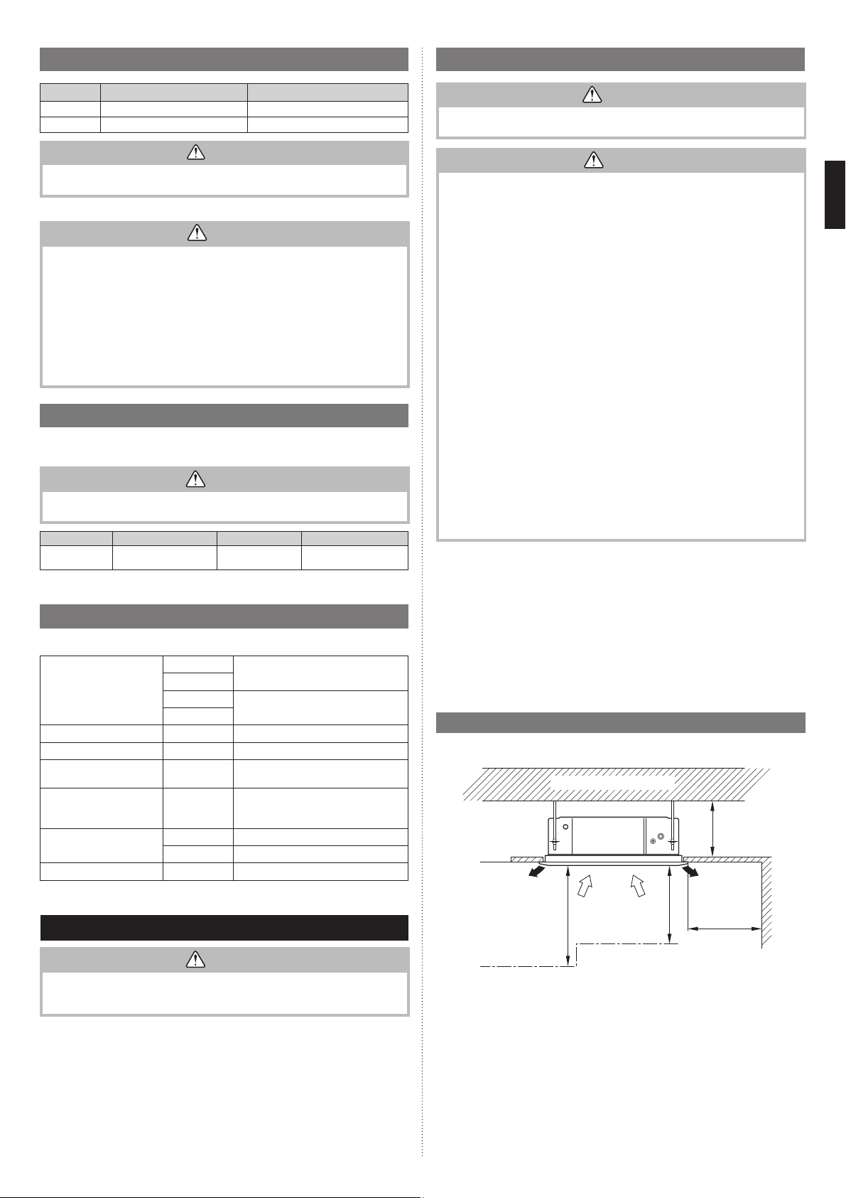
3.2. Installation dimensions
• The ceiling rear height as shown in the fi gure.
Strong and durable ceiling
1,800 or
more
Obstruction
1,000 or
more
(Unit: mm)
262 or
more
1,000 or
more
WARNING
Do not move the appliance by holding the indoor unit pipes.
(The stress applied to the pipe joints may cause the fl ammable gas to leak during
operation.)
Especially, the installation place is very important for the split type air conditioner because
it is very diffi cult to move from place to place after the fi rst installation.
Floor
• This product can be installed at a height of up to 3,000mm.
However, 7000, 9000 Btu/h model can not be installed in high places.
Perform the Function Setting on the remote control in accordance with the installed height.
“7. FUNCTION SETTING”)
(Refer to
En-5
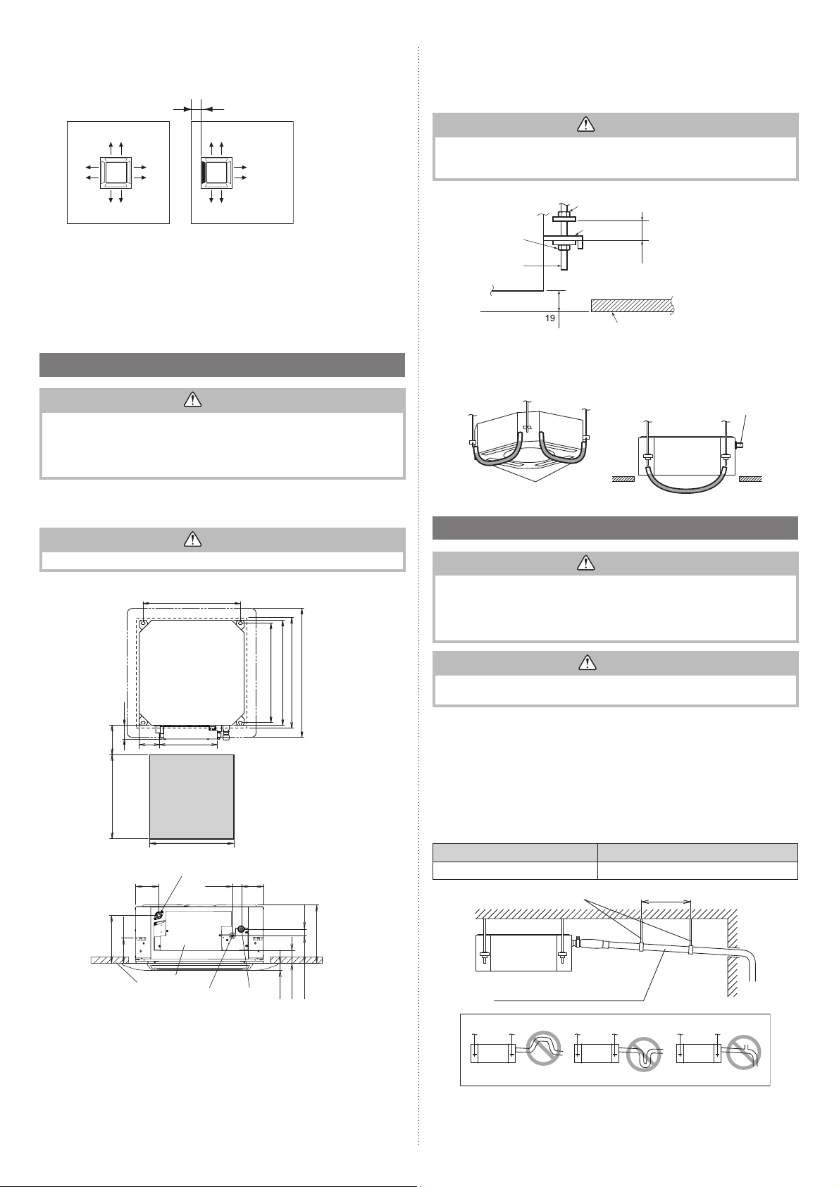
■Discharge direction setting
• The discharge direction can be selected as shown below.
100 or more*
(Unit: mm)
3.3.2. Body installation
(1) Install special nut A, then special nut B onto the hanging bolt.
(2) Raise the body and mount its hooks onto the hanging bolt between the special nuts.
(3)Turn special nut B to adjust the height of the body.
*Please ensure
suffi cient
service access
during installation.
(4 directions) (3 directions)
• For a 3-way outlet, make sure to perform the Function Setting on the remote control.
Also, make sure to use the optional shutter plate to block the outlet.
• The ceiling height cannot be set in the 3-way outlet mode. Therefore, do not change the
setting in the setting the ceiling height. (Refer to “7. FUNCTION SETTING”)
• When the outlet is shut, be sure to install the optional Air outlet shutter plate kit.
For the details of installation, please refer to Installation Manual of kit.
3.3. Installing the unit
WARNING
• Install the air conditioner in a location which can withstand a load of at least 5 times the
weight of the main unit and which will not amplify sound or vibration. If the installation
location is not strong enough, the indoor unit may fall and cause injuries.
• If the job is done with the panel frame only, there is a risk that the unit will come loose.
Please take care.
3.3.1. Position the ceiling hole and hanging bolts
Ceiling openings and hanging bolt installation diagram.
WARNING
When fastening the hangers, make the bolt positions uniform.
(Unit: mm)
530 (Hanging bolt position)
WARNING
• Perform fi nal tightening by tightening the double nut fi rmly.
• Be sure to install the body horizontally and adjust the height below the body and the
ceiling surface properly.
(Unit: mm)
Special nut B
(accessories)
Hanging bolt
Special nut A
(accessories)
Hook
30
or more
Ceiling
After installing the
body, tighten the nuts.
3.3.3. Leveling
Using a level, or vinyl hose filled with water, fine adjust so that the body is level.
Inclined installation so as the drain pipe side is higher may cause a malfunction of the float
switch, and may cause water leakage.
Drain pipe
Vinyl hoses
3.4. Drain installation
WARNING
• Do not insert the drain piping into the sewer where sulfurous gas occurs. (Heat exchange erosion may occur)
• Insulate the parts properly so that water will not drip from the connection parts.
• Check for proper drainage after installation by using the visible portion of transparent
drain port and the drain piping fi nal outlet on the body.
570(Indoor unit)
75
250
135
150 to 200
service access
Min.450
Min.450
Drain pipe (O.D.ø26.1)
102
114
215
Control box
Ceiling
Be sure to keep suffi cient space in the designated position for future maintenance.
40
Liquid pipe
99
Gas pipe
620 (Cassette Grille)
540 (Hanging bolt position)
580 to 610 (Ceiling openings)
30
262
58
123
30
CAUTION
Do not apply adhesive agent on the drain port of the body. (Use the attached drain hose
assembly to connect the drain piping)
3.4.1. Installing the drain pipe
■When not lifting up drain pipe:
• Install the drain pipe with downward gradient (1/50 to 1/100) and so there are no rises or
traps in the pipe.
• Use general hard polyvinyl chloride pipe (VP25) [outside diameter 32mm] and connect it
with adhesive (polyvinyl chloride) so that there is no leakage.
• When the pipe is long, install supporters.
• Do not perform air bleeding.
• Always heat insulate indoor section of drain pipe.
• If it is impossible to have suffi cient gradient of pipe, perform drain lift-up.
Pipe size
Drain pipe VP25 (O.D. 32 mm)
Hanging fi ttings
VP25 (O.D. 32 mm)
Downward gradient 1/100 to 1/50
PROHIBITED:
1.5 to 2 m
En-6
Rise
Trap
Air bleeding
 Loading...