

Page 1

AIR CONDITIONER
Cassette type
Contents
1. SAFETY PRECAUTIONS ……………………………………………… 1
2. PRODUCT SPECIFICATION …………………………………………… 4
2.1. Installation tools …………………………………………………… 4
2.2. Accessories ………………………………………………………… 4
2.3. Pipe requirement ……………………………………………………4
2.4. Electrical requirement ………………………………………………5
2.5. Optional parts ………………………………………………………5
3. INSTALLATION WORK ………………………………………………… 5
3.1. Selecting an installation location ………………………………… 5
3.2. Installation dimension ……………………………………………… 6
3.3. Installing the unit …………………………………………………… 6
3.4. Drain installation …………………………………………………… 7
3.5. Pipe installation …………………………………………………… 8
3.6. Electrical wiring …………………………………………………… 9
3.7. Remote controller installation …………………………………… 11
4. CASSETTE GRILLE INSTALLATION ………………………………… 11
5. OPTIONAL INSTALLATION WORK ………………………………… 11
5.1. Optional kit installation ………………………………………… 11
5.2. External input and output ……………………………………… 11
6. REMOTE CONTROL INSTALLATION ……………………………… 12
6.1. Group control …………………………………………………… 12
6.2. Multiple remote control ………………………………………… 13
7. FUNCTION SETTING ………………………………………………… 13
7.1. Function Details ………………………………………………… 13
8. CHECK LIST …………………………………………………………… 15
9. TEST RUN ……………………………………………………………… 15
10. FINISHING ……………………………………………………………… 15
11. CUSTOMER GUIDANCE ……………………………………………… 15
12. ERROR CODES ……………………………………………………… 15
NOTES: This manual describes how to install the air conditioner described above.
Handling and installation shall only be done by professionals as outlined in
this manual.
1. SAFETY PRECAUTIONS
• Be sure to read this manual thoroughly before installation.
• The warnings and precautions indicated in this manual contain important information
pertaining to your safety. Be sure to observe them.
• Hand this manual, together with the operating manual, to the customer. Request the
customer to keep them on hand for future use, such as for relocating or repairing the unit.
WARNING
CAUTION
Indicates a potentially or imminently hazardous situation
which, if not avoided, could result in death or serious injury.
Indicates a potentially hazardous situation that may result in
minor or moderate injury or damage to property.
INSTALLATION MANUAL
PART No. 9381798070
[Original instructions] For authorized service personnel only.
WARNING
• The appliance shall be installed, operated and stored in a room with a fl oor area larger
than X m².
Amount of refrigerant charge
• Installation of this product must be done by experienced service technicians or professional installers only in accordance with this manual. Installation by non-professional
or improper installation of the product might cause serious accidents such as injury,
water leakage, electric shock, or fi re. If the product is installed in disregard of the
instructions in this manual, it will void the manufacturer’s warranty.
• Do not turn on the power until all work has been completed. Turning on the power before the work is completed can cause serious accidents such as electric shock or fi re.
• If refrigerant leaks when you are working, ventilate the area. If the leaking refrigerant
is exposed to a direct fl ame, it may produce a toxic gas.
• Installation must be performed in accordance with regulations, codes, or standards for
electrical wiring and equipment in each country, region, or the installation place.
• Do not use means to accelerate the defrosting process or to clean, other than those
recommended by the manufacturer.
• This appliance is not intended for use by persons (including children) with reduced
physical, sensory or mental capabilities, or lack of experience and knowledge, unless
they have been given supervision or instruction concerning use of the appliance by a
person responsible for their safety. Children should be supervised to ensure that they
do not play with the appliance.
• To avoid danger of suffocation, keep the plastic bag or thin fi lm used as the packaging
material away from young children.
• The appliance shall be stored in a room without continuously operating ignition
sources (for example: open fl ames, an operating gas appliance or an operating
electric heater).
• Do not pierce or burn.
• Be aware that refrigerants may not contain an odour.
M (kg)
M ≤ 1.22 -
1.22 < M ≤ 1.23 1.45
1.23 < M ≤ 1.50 2.15
1.50 < M ≤ 1.75 2.92
1.75 < M ≤ 2.0 3.82
2.0 < M ≤ 2.5 5.96
2.5 < M ≤ 3.0 8.59
3.0 < M ≤ 3.5 11.68
3.5 < M ≤ 4.0 15.26
CAUTION
• Read carefully all safety information written in this manual before you install or use the
air conditioner.
• Install the product by following local codes and regulations in force at the place of
installation, and the instructions provided by the manufacturer.
• This product is part of a set constituting an air conditioner. The product must not be
installed alone or be installed with a device not authorized by the manufacturer.
• Always use a separate power supply line protected by a circuit breaker operating on
all wires with a distance between contact of 3 mm for this product.
• To protect the persons, earth (ground) the product correctly, and use the power cable
combined with an Earth Leakage Circuit Breaker (ELCB).
• This product is not explosion proof, and therefore should not be installed in an explosive atmosphere.
• To avoid getting an electric shock, never touch the electrical components soon after
the power supply has been turned off. After turning off the power, always wait 5 minutes or more before you touch the electrical components.
• This product contains no user-serviceable parts. Always consult experienced service
technicians for repairing.
• When moving or relocating the air conditioner, consult experienced service technicians
for disconnection and reinstallation of the product.
• Do not touch the aluminum fi ns of heat exchanger built-in the indoor or outdoor unit to
avoid personal injury when you install or maintain the unit.
• Do not place any other electrical products or household belongings under the product.
Condensation dripping from the product might get them wet, and may cause damage
or malfunction to the property.
• Be careful not to scratch the air conditioner when handling it.
Minimum room area
X (m2)
(IEC 60335-2-40)
EnglishDeutschFrançaisEspañolItalianoEλληvIkάPortuguêsРусский
Türkçe
Türkçe
En-1
Page 2
Precautions for using R32 refrigerant
The basic installation work procedures are the same as conventional refrigerant (R410A,
R22) models.
However, pay careful attention to the following points:
Since the working pressure is 1.6 times higher than that of refrigerant R22 models,
some of the piping and installation and service tools are special. (Refer to “2. 1. Installation tools”.)
Especially, when replacing a refrigerant R22 model with a new refrigerant R32 model,
always replace the conventional piping and flare nuts with the R32 and R410A piping and
fl are nuts on the outdoor unit side.
For R32 and R410A, the same fl are nut on the outdoor unit side and pipe can be used.
Models that use refrigerant R32 and R410A have a different charging port thread diameter to prevent erroneous charging with refrigerant R22 and for safety. Therefore, check
beforehand. [The charging port thread diameter for R32 and R410A is 1/2-20 UNF.]
Be more careful than R22 so that foreign matter (oil, water, etc.) does not enter the
piping. Also, when storing the piping, securely seal the opening by pinching, taping, etc.
(Handling of R32 is similar to R410A.)
CAUTION
1-Installation (Space)
• That the installation of pipe-work shall be kept to a minimum.
• That pipe-work shall be protected from physical damage.
• The appliance shall not be installed in an unventilated space, if that space is smaller
than X m².
Amount of refrigerant charge
• That compliance with national gas regulations shall be observed.
• That mechanical connections shall be accessible for maintenance purposes.
• In cases that require mechanical ventilation, ventilation openings shall be kept clear
of obstruction.
• When disposing of the product is used, be based on national regulations, properly
processed.
2-Servicing
2-1 Service personnel
• Any person who is involved with working on or breaking into a refrigerant circuit
should hold a current valid certifi cate from an industry-accredited assessment
authority, which authorises their competence to handle refrigerants safely in accordance with an industry recognised assessment specifi cation.
• Servicing shall only be performed as recommended by the equipment manufacturer.
Maintenance and repair requiring the assistance of other skilled personnel shall be
carried out under the supervision of the person competent in the use of fl ammable
refrigerants.
• Servicing shall be performed only as recommended by the manufacturer.
2-2 Work
• Prior to beginning work on systems containing fl ammable refrigerants, safety checks
are necessary to ensure that the risk of ignition is minimized. For repair to the refrigerating system, the precautions in 2-2 to 2-8 shall be complied with prior to conducting work on the system.
• Work shall be undertaken under a controlled procedure so as to minimize the risk of
a fl ammable gas or vapour being present while the work is being performed.
• All maintenance staff and others working in the local area shall be instructed on the
nature of work being carried out.
• Work in confi ned spaces shall be avoided.
• The area around the workspace shall be sectioned off.
• Ensure that the conditions within the area have been made safe by control of fl am-
mable material.
2-3 Checking for presence of refrigerant
• The area shall be checked with an appropriate refrigerant detector prior to and during
work, to ensure the technician is aware of potentially fl ammable atmospheres.
• Ensure that the leak detection equipment being used is suitable for use with fl am-
mable refrigerants, i.e. nonsparking, adequately sealed or intrinsically safe.
M (kg)
M ≤ 1.22 -
1.22 < M ≤ 1.23 1.45
1.23 < M ≤ 1.50 2.15
1.50 < M ≤ 1.75 2.92
1.75 < M ≤ 2.0 3.82
2.0 < M ≤ 2.5 5.96
2.5 < M ≤ 3.0 8.59
3.0 < M ≤ 3.5 11.68
3.5 < M ≤ 4.0 15.26
Minimum room area
X (m2)
(IEC 60335-2-40)
CAUTION
2-4 Presence of fi re extinguisher
• If any hot work is to be conducted on the refrigeration equipment or any associated
parts, appropriate fi re extinguishing equipment shall be available at hand.
• Have a dry powder or CO
2-5 No ignition sources
• No person carrying out work in relation to a refrigeration system which involves
exposing any pipe work that contains or has contained fl ammable refrigerant shall
use any sources of ignition in such a manner that it may lead to the risk of fi re or
explosion.
• All possible ignition sources, including cigarette smoking, should be kept suffi ciently
far away from the site of installation, repairing, removing and disposal, during which
fl ammable refrigerant can possibly be released to the surrounding space.
• Prior to work taking place, the area around the equipment is to be surveyed to make
sure that there are no fl ammable hazards or ignition risks. “No Smoking” signs shall
be displayed.
2-6 Ventilated area
• Ensure that the area is in the open or that it is adequately ventilated before breaking
into the system or conducting any hot work.
• A degree of ventilation shall continue during the period that the work is carried out.
• The ventilation should safely disperse any released refrigerant and preferably expel
it externally into the atmosphere.
2-7 Checks to the refrigeration equipment
• Where electrical components are being changed, they shall be fi t for the purpose
and to the correct specifi cation.
• At all times the manufacturer’s maintenance and service guidelines shall be followed.
• If in doubt consult the manufacturer’s technical department for assistance.
• The following checks shall be applied to installations using fl ammable refrigerants.
- The charge size is in accordance with the room size within which the refrigerant
containing parts are installed.
- The ventilation machinery and outlets are operating adequately and are not
obstructed.
- If an indirect refrigerating circuit is being used, the secondary circuit shall be
checked for the presence of refrigerant.
- Marking to the equipment continues to be visible and legible. Markings and signs
that are illegible shall be corrected.
- Refrigeration pipe or components are installed in a position where they are unlikely
to be exposed to any substance which may corrode refrigerant containing components, unless the components are constructed of materials which are inherently
resistant to being corroded or are suitably protected against being so corroded.
2-8 Checks to electrical devices
• Repair and maintenance to electrical components shall include initial safety checks
and component inspection procedures.
• If a fault exists that could compromise safety, then no electrical supply shall be connected to the circuit until it is satisfactorily dealt with.
• If the fault cannot be corrected immediately but it is necessary to continue operation,
an adequate temporary solution shall be used.
• This shall be reported to the owner of the equipment so all parties are advised.
• Initial safety checks shall include.
- That capacitors are discharged: this shall be done in a safe manner to avoid possibility of sparking.
- That there no live electrical components and wiring are exposed while charging,
recovering or purging the system.
- That there is continuity of earth bonding.
3-Repairs to sealed components
• During repairs to sealed components, all electrical supplies shall be disconnected
from the equipment being worked upon prior to any removal of sealed covers, etc.
• If it is absolutely necessary to have an electrical supply to equipment during servicing, then a permanently operating form of leak detection shall be located at the most
critical point to warn of a potentially hazardous situation.
• Particular attention shall be paid to the following to ensure that by working on electrical components, the casing is not altered in such a way that the level of protection is
affected.
• This shall include damage to cables, excessive number of connections, terminals not
made to original specifi cation, damage to seals, incorrect fi tting of glands, etc.
• Ensure that apparatus is mounted securely.
• Ensure that seals or sealing materials have not degraded such that they no longer
serve the purpose of preventing the ingress of fl ammable atmospheres.
• Replacement parts shall be in accordance with the manufacturer’s specifi cations.
NOTES: The use of silicon sealant may inhibit the effectiveness of some types of leak
detection equipment.
Intrinsically safe components do not have to be isolated prior to working on
them.
fi re extinguisher adjacent to the charging area.
2
En-2
Page 3

CAUTION
4-Repair to intrinsically safe components
• Do not apply any permanent inductive or capacitance loads to the circuit without
ensuring that this will not exceed the permissible voltage and current permitted for
the equipment in use.
• Intrinsically safe components are the only types that can be worked on while live in
the presence of a fl ammable atmosphere.
• The test apparatus shall be at the correct rating.
• Replace components only with parts specifi ed by the manufacturer.
• Other parts may result in the ignition of refrigerant in the atmosphere from a leak.
5-Cabling
• Check that cabling will not be subject to wear, corrosion, excessive pressure, vibration, sharp edges or any other adverse environmental effects.
• The check shall also take into account the effects of aging or continual vibration from
sources such as compressors or fans.
6-Detection of fl ammable refrigerants
• Under no circumstances shall potential sources of ignition be used in the searching
for or detection of refrigerant leaks.
• A halide torch (or any other detector using a naked fl ame) shall not be used.
7-Leak detection methods
• Electronic leak detectors shall be used to detect fl ammable refrigerants, but the
sensitivity may not be adequate, or may need re-calibration. (Detection equipment
shall be calibrated in a refrigerant-free area.)
• Ensure that the detector is not a potential source of ignition and is suitable for the
refrigerant used.
• Leak detection equipment shall be set at a percentage of the LFL of the refrigerant
and shall be calibrated to the refrigerant employed and the appropriate percentage of
gas (25 % maximum) is confi rmed.
• Leak detection fl uids are suitable for use with most refrigerants but the use of
detergents containing chlorine shall be avoided as the chlorine may react with the
refrigerant and corrode the copper pipe-work.
• If a leak is suspected, all naked fl ames shall be removed/extinguished.
• If a leakage of refrigerant is found which requires brazing, all of the refrigerant shall
be recovered from the system, or isolated (by means of shut off valves) in a part of
the system remote from the leak.
Oxygen free nitrogen (OFN) shall then be purged through the system both before
and during the brazing process.
8-Removal and evacuation
• When breaking into the refrigerant circuit to make repairs – or for any other
purpose –conventional procedures shall be used.
However, it is important that best practice is followed since fl ammability is a consid-
eration.
The following procedure shall be adhered to:
• remove refrigerant
• purge the circuit with inert gas
• evacuate
• purge again with inert gas
• open the circuit by cutting or brazing
• The refrigerant charge shall be recovered into the correct recovery cylinders.
• The system shall be “fl ushed” with OFN to render the unit safe.
• This process may need to be repeated several times.
• Compressed air or oxygen shall not be used for this task.
• Flushing shall be achieved by breaking the vacuum in the system with OFN and
continuing to fi ll until the working pressure is achieved, then venting to atmosphere,
and fi nally pulling down to a vacuum.
• This process shall be repeated until no refrigerant is within the system.
• When the fi nal OFN charge is used, the system shall be vented down to atmospheric
pressure to enable work to take place.
• This operation is absolutely vital if brazing operations on the pipe work are to take
place.
• Ensure that the outlet for the vacuum pump is not close to any ignition sources and
there is ventilation available.
9-Charging procedures
• In addition to conventional charging procedures, the following requirements shall be
followed.
- Ensure that contamination of different refrigerants does not occur when using
charging equipment.
Hoses or lines shall be as short as possible to minimize the amount of refrigerant
contained in them.
- Cylinders shall be kept upright.
- Ensure that the refrigeration system is earthed prior to charging the system with
refrigerant.
- Label the system when charging is complete (if not already).
- Extreme care shall be taken not to overfi ll the refrigeration system.
• Prior to recharging the system it shall be pressure tested with OFN.
• The system shall be leak tested on completion of charging but prior to commissioning.
• A follow up leak test shall be carried out prior to leaving the site.
CAUTION
10-Decommissioning
• Before carrying out this procedure, it is essential that the technician is completely
familiar with the equipment and all its details.
• It is recommended good practice that all refrigerants are recovered safely.
• Prior to the task being carried out, an oil and refrigerant sample shall be taken in
case analysis is required prior to re-use of reclaimed refrigerant.
• It is essential that electrical power is available before the task is commenced.
a) Become familiar with the equipment and its operation.
b) Isolate system electrically.
c) Before attempting the procedure ensure that:
• mechanical handling equipment is available, if required, for handling refrigerant cylinders;
• all personal protective equipment is available and being used correctly;
• the recovery process is supervised at all times by a competent person;
• recovery equipment and cylinders conform to the appropriate standards.
d) Pump down refrigerant system, if possible.
e) If a vacuum is not possible, make a manifold so that refrigerant can be removed
from various parts of the system.
f) Make sure that cylinder is situated on the scales before recovery takes place.
g) Start the recovery machine and operate in accordance with manufacturer ’s
instructions.
h) Do not overfi ll cylinders. (No more than 80 % volume liquid charge).
i) Do not exceed the maximum working pressure of the cylinder, even temporarily.
j) When the cylinders have been fi lled correctly and the process completed, make
sure that the cylinders and the equipment are removed from site promptly and all
isolation valves on the equipment are closed off.
k) Recovered refrigerant shall not be charged into another refrigeration system un-
less it has been cleaned and checked.
11-Labelling
• Equipment shall be labelled stating that it has been de-commissioned and emptied
of refrigerant.
• The label shall be dated and signed.
• Ensure that there are labels on the equipment stating the equipment contains fl am-
mable refrigerant.
12-Recovery
• When removing refrigerant from a system, either for servicing or decommissioning, it
is recommended good practice that all refrigerants are removed safely.
• When transferring refrigerant into cylinders, ensure that only appropriate refrigerant
recovery cylinders are employed.
• Ensure that the correct number of cylinders for holding the total system charge are
available.
• All cylinders to be used are designated for the recovered refrigerant and labelled for
that refrigerant (i.e. special cylinders for the recovery of refrigerant).
• Cylinders shall be complete with pressure relief valve and associated shut-off valves
in good working order.
• Empty recovery cylinders are evacuated and, if possible, cooled before recovery
occurs.
• The recovery equipment shall be in good working order with a set of instructions
concerning the equipment that is at hand and shall be suitable for the recovery of
fl ammable refrigerants.
• In addition, a set of calibrated weighing scales shall be available and in good working
order.
• Hoses shall be complete with leak-free disconnect couplings and in good condition.
• Before using the recovery machine, check that it is in satisfactory working order, has
been properly maintained and that any associated electrical components are sealed
to prevent ignition in the event of a refrigerant release.
Consult manufacturer if in doubt.
• The recovered refrigerant shall be returned to the refrigerant supplier in the correct
recovery cylinder, and the relevant Waste Transfer Note arranged.
• Do not mix refrigerants in recovery units and especially not in cylinders.
• If compressors or compressor oils are to be removed, ensure that they have been
evacuated to an acceptable level to make certain that fl ammable refrigerant does not
remain within the lubricant.
• The evacuation process shall be carried out prior to returning the compressor to the
suppliers.
• Only electric heating to the compressor body shall be employed to accelerate this
process.
• When oil is drained from a system, it shall be carried out safely.
En-3
Page 4
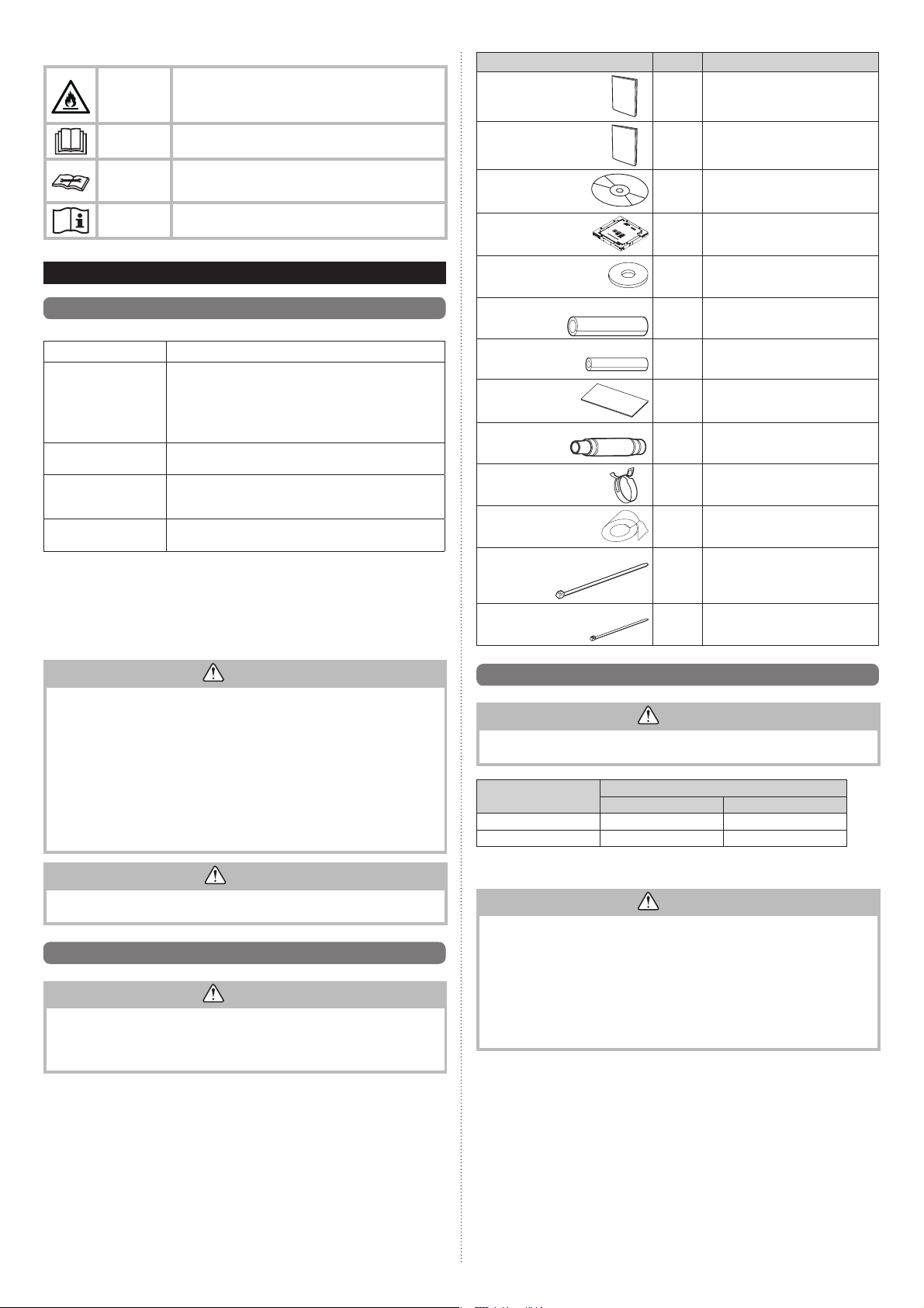
Explanation of symbols displayed on the indoor unit or outdoor unit.
This symbol shows that this appliance uses a fl ammable
WARNING
CAUTION
CAUTION
CAUTION
refrigerant.
If the refrigerant is leaked and exposed to an external ignition source, there is a risk of fi re.
This symbol shows that the operation manual should be
read carefully.
This symbol shows that a service personnel should be
handling this equipment with reference to the installation
manual.
This symbol shows that information is available such as
the operating manual or installation manual.
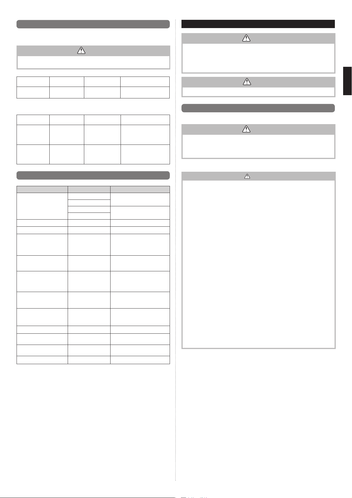
2. PRODUCT SPECIFICATION
Name and Shape Q’ty Description
Installation manual
Operating manual
CD-ROM
Template
(Carton top)
Washer
(This book)
1
1–
1–
For installing indoor unit
1
For installing indoor unit
8
2. 1. Installation tools
Tool name Change from R22 to R32 (R410A)
Pressure is high and cannot be measured with a R22
Gauge manifold
Charge hose
Vacuum pump
Gas leakage detector
Copper pipes
It is necessary to use seamless copper pipes and it is desirable that the amount of residual
oil is less than 40 mg/10 m. Do not use copper pipes having a collapsed, deformed or
discolored portion (especially on the interior surface). Otherwise, the expansion value or
capillary tube may become blocked with contaminants.
As an air conditioner using R32 (R410A) incurs pressure higher than when using R22, it is
necessary to choose adequate materials.
gauge. To prevent erroneous mixing of other refrigerants,
the diameter of each port has been changed.
It is recommended to use gauge with seals -0.1 to 5.3 MPa
(-1 to 53 bar) for high pressure.
-0.1 to 3.8 MPa (-1 to 38 bar) for low pressure.
To increase pressure resistance, the hose material and base
size were changed. (R32/R410A)
A conventional vacuum pump can be used by installing a
vacuum pump adapter.
(Use of a vacuum pump with a series motor is prohibited.)
Special gas leakage detector for HFC refrigerant R410A or
R32.
WARNING
• Do not use the existing (for R22) piping and fl are nuts.
If the existing materials are used, the pressure inside the refrigerant cycle will rise and
cause failure, injury, etc. (Use the special R32/R410A materials.)
• Use (refi ll or replace with) specifi ed refrigerant (R32) only. Use of unspecifi ed refriger-
ant can cause product malfunction, burst, or injury.
• Do not mix any gas or impurities except specifi ed refrigerant (R32). Infl ow of air or ap-
plication of unspecifi ed material makes the internal pressure of the refrigerant cycle too
high, and may cause product malfunction, burst of piping, or injury.
• For installation purposes, be sure to use the parts supplied by the manufacturer or
other prescribed parts. The use of non-prescribed parts can cause serious accidents
such as the unit falling, water leakage, electric shock, or fi re.
• Do not turn on the power until all work has been completed.
Coupler heat insulation (Large)
Coupler heat insulation (Small)
Insulation
Drain hose
Hose Band
Drain hose heat insulation
Cable tie (Large)
Cable tie (Small)
For indoor side pipe joint (Gas pipe)
1
For indoor side pipe joint
1
(Liquid pipe)
For installing drain pipe
1
For installing drain pipe
1
VP25 (O.D.32, I.D.25)
For installing drain hose
1
For installing drain pipe
1
For connection pipe fi xing.
4
Only one is used for this model.
2
2. 3. Pipe requirement
CAUTION
Refer to the installation manual of the outdoor unit for description of the length of connecting pipe or for difference of its elevation.
Model
18/22/24 12.70 (1/2) 6.35 (1/4)
30/36/45/54 15.88 (5/8) 9.52 (3/8)
Diameter [mm (in)]
Gas pipe Liquid pipe
CAUTION
This manual describes how to install the indoor unit only. To install the outdoor unit or
branch box, (if any), refer to the installation manual included in each product.
2. 2. Accessories
WARNING
• For installation purposes, be sure to use the parts supplied by the manufacturer or
other prescribed parts.
• The use of non-prescribed parts can cause serious accidents such as the unit falling,
water leakage, electric shock, or fi re.
• The following installation parts are furnished. Use them as required.
• Keep the installation manual in a safe place and do not discard any other accessories
until the installation work has been completed.
En-4
• Use pipe with water-resistant heat insulation.
CAUTION
Install heat insulation around both the gas and liquid pipes. Failure to do so may cause
water leaks.
Use heat insulation with heat resistance above 120 °C. (Reverse cycle model only)
In addition, if the humidity level at the installation location of the refrigerant piping is
expected to exceed 70 %, install heat insulation around the refrigerant piping.
If the expected humidity level is 70-80 %, use heat insulation that is 15 mm or thicker
and if the expected humidity exceeds 80 %, use heat insulation that is 20 mm or thicker.
If heat insulation is used that is not as thick as specifi ed, condensation may form on the
surface of the insulation.
In addition, use heat insulation with heat conductivity of 0.045 W/(m·K) or less (at 20 °C).
Page 5
2. 4. Electrical requirement
3. INSTALLATION WORK
The indoor unit is powered from the outdoor unit. Do not power indoor unit from separate
power source.
WARNING
Standard for electrical wiring and equipment differs in each country or region. Before you
start electrical working, confi rm related regulations, codes, or standards.
Conductor size
Cable
Connection cable 1.5 (MIN.) Type 60245 IEC57
Max. Cable Length: Limit voltage drop to less than 2%. Increase cable gauge if voltage
drop is 2% or more.
Cable
Remote controller
cable
(2-wire type)
Remote controller
cable
(3-wire type)
2
)
(mm
Conductor size
2
)
(mm
0.33 to 1.25
0.33
Type
Type
Sheathed PVC
cable
Sheathed PVC
cable
Remarks
3Wire+Earth (Ground),
1φ230V
Remarks
Non-polar 2 wire, twisted
pair
Polar 3 wire
2. 5. Optional parts
Parts name Model No. Application
UTY-RNR*Z* For air conditioner operation
Wired remote controller
W-LAN interface UTY-TFSXZ1 For wireless LAN control
IR receiver unit UTY-LBT*C For air conditioner operation
Human sensor UTY-SHZXC
Wide panel UTG-AKXA-W
Panel spacer UTG-BKXA-W
Air outlet shutter plate UTR-YDZK
Insulation kit for High
humidity
Fresh air intake kit UTZ-VXRA To take fresh air
External input and output
PCB
External input and output
PCB box
External connect kit UTY-XWZXZG For control output port
UTY-RLR*
UTY-RVN*M For air conditioner operation
UTY-RNN*M
UTZ-KXRA
UTY-XCSX For connecting external devices
UTZ-GXRA
(2-wired type)
(3-wired type)
To prevent waste of electricity,
this function controls the temperature setting when no one is
occupying the room.
Wide panel hides the gap
between the ceiling hole and the
Cassette grille.
Installation in a space of 56 mm
or greater is possible by using
panel spacer when the height
behind the ceiling is low.
Install the plate at outlet when
carrying out 3-way direction
operation
Install when the condition under
the roof is over 80% in humidity
and over 30°C in temperature.
For installing the External input
and output PCB
WARNING
• Do not turn on the power until all installation work is complete.
• Carrying and installation of the unit should be performed by a suffi cient number of
people and with suffi cient equipment that is adequate for the weight of the unit.
• Performing such work with an insuffi cient number of people or with inadequate equip-
ment could result in dropping of the unit or personal injury.
CAUTION
For installation details, refer to the technical data.
3. 1. Selecting an installation location
Decide the mounting position together with the customer as follows.
WARNING
• Select installation locations that can properly support the weight of the indoor unit
and which will not amplify sound or vibration. If the installation location is not strong
enough, the indoor unit may fall and cause injuries.
• Install the units securely so that they do not topple or fall.
CAUTION
• Do not install the indoor unit in the following areas:
–
Area with high salt content, such as at the seaside.
It will deteriorate metal parts, causing the parts to fall or the unit to leak water.
–
Area fi lled with mineral oil or containing a large amount of splashed oil or steam,
such as a kitchen.
It will deteriorate plastic parts, causing the parts to fall or the unit to leak water.
–
Area that generates substances that adversely affect the equipment, such as sulfuric
gas, chlorine gas, acid, or alkali. It will cause the copper pipes and brazed joints to
corrode, which can cause refrigerant leakage.
–
Area that can cause combustible gas to leak, contains suspended carbon fi bers or
fl ammable dust, or volatile infl ammables such as paint thinner or gasoline. If gas
leaks and settles around the unit, it can cause a fi re.
–
Area where animals may urinate on the unit or ammonia may be generated.
• Do not use the unit for special purposes, such as storing food, raising animals, growing plants, or preserving precision devices or art objects. It can degrade the quality of
the preserved or stored objects.
• Do not install where there is the danger of combustible gas leakage.
• Do not install the unit near a source of heat, steam, or fl ammable gas.
• Install the unit where drainage does not cause any trouble.
• Install the indoor unit, outdoor unit, power supply cable, transmission cable, and
remote control cable at least 1 m away from a television or radio receivers. The
purpose of this is to prevent TV reception interference or radio noise.
(Even if they are installed more than 1 m apart, you could still receive noise under
some signal conditions.)
• Install the unit where ambient temperature does not reach 60°C or more.
Take a measure such as ventilation for an environment in which heat is retained.
• If children under 10 years old may approach the unit, take preventive measures so
that they cannot reach the unit.
• Install the indoor unit on the place where the height from the fl oor is more than 1.8 m.
• Use the “Insulation kit for high humidity” (option), when the condition under the roof
is over 80% in humidity and over 30°C in temperature. Otherwise, there is a risk of
condensation on the ceiling.
(1) Locate where the air can be distributed evenly throughout the room by the unit.
(2) The inlet and outlet ports should not be obstructed; the air should be able to blow all
over the room.
(3) Leave the space required to service the air conditioner.
(4) Install the unit where connection to the outdoor unit is easy.
(5) Install the unit where the connection pipe can be easily installed.
(6) Install the unit where the drain pipe can be easily installed.
(7) Install the unit where noise and vibrations are not amplifi ed.
(8) Take servicing, etc., into consideration and leave the spaces. Also install the unit where
the fi lter can be removed.
(9) Do not install the unit where it will be exposed to direct sunlight.
Correct initial installation location is important because it is diffi cult to move unit after it is
installed.
En-5
Page 6

3. 2. Installation dimension
• Refrigerant piping and drain piping positions.
Unit: mm
• The ceiling rear height as shown in the fi gure.
Strong and durable ceiling
3 or more
1 or more
1.8 or more
Floor
• This product can be installed at a height of up to 4.2 m. However, if the heights of the
ceiling is higher than 3.2 m or lower than 2.7 m, it is necessary to set the position from
remote controller. (Refer to “7. FUNCTION SETTING”)
Discharge direction setting
• The discharge direction can be selected as shown below.
100 or more*
* Please ensure suffi -
(4 directions) (3 directions)
• For a 3-way outlet, make sure to perform the function setting on the remote control.
Also, make sure to use the optional shutter plate to block the outlet.
• The ceiling height cannot be set in the 3-way outlet mode. Therefore, do not change the
setting in the setting the ceiling height. (Refer to “7. FUNCTION SETTING”)
• When the outlet is shut, be sure to install the optional Air outlet shutter plate kit. For the
details of installation, please refer to installation manual of the kit.
Unit: m
1.5 or
more
Obstruction
Unit : mm
cient service access
during installation.
3. 3. Installing the unit
352
Gas pipe
45
100
237
80
83
Cut out
10 ×
4 ×
140
180
3.2 hole
95
Cut out
3.2 hole
163
163
10
Liquid pipe
Drain pipe
(Connect the
attached drain
hose)
200
• Distribution ducts and fresh air inlet positions.
Distribution duct connecting port
Distribution duct connecting port
Fresh air inlet
position
Drain pipe
Distribution duct connecting port
342
Refrigerant pipe
293
90
Detailed diagram of distribution duct
connecting port (4 sides)
Distribution duct
connecting port
114
bolt pitch
100
83
Fresh air inlet position
NOTES:
Conduct proper insulation when connecting the distribution ducts and fresh air inlet.
Insulation
Unit: mm
WARNING
• Carrying and installation of the unit should be performed by a suffi cient number
of people and with suffi cient equipment that is adequate for the weight of the unit.
Performing such work with an insuffi cient number of people or with inadequate
equipment could result in dropping of the unit or personal injury.
• If the job is done with the panel frame only, there is a risk that the unit will come
loose. Please take care.
• When fastening the hangers, make the bolt positions uniform.
3.3.1. Position the ceiling hole and hanging bolts
(1) Positions of the ceiling opening, hanging bolt pitch, piping and ducts.
• Ceiling opening and hanging bolt pitch.
950(Panel frame)
860 - 910(Ceiling opening)
20 - 45
840(Body frame)
796(Hanging bolt pitch)
768(Hanging bolt pitch)
130
130
200
20 - 45
50 - 100
200 - 205
20 - 45
A
39
80
840(Body frame)
950(Panel frame)
860 - 910(Ceiling opening)
50
130
Model
18/22/24 246 256
20 - 45
30/36/45/54 288 298
10
Dimension (mm)
AB
Unit: mm
B
Fresh air inlet position
NOTES:
When introducing fresh air into the indoor unit, please remove the insulation affi xed to the
drain pan.
(2) Setting the positions of hanging bolt and ceiling opening.
• Use an installation template (packaging top surface) to set the positions of the hanging
bolt and ceiling opening and drill holes.
(3) Hanging structure.
• Select a strong structure for the hanging location.
• If necessary, reinforce the hanging bolt with quake proof columnar support material to
prevent shaking.
• Use hanging bolts of M8-M10.
3.3.2. Body installation
(1) Install the attached washer and nut (prepared on site) onto the hanging bolt.
(2) Hook the body onto the hanging bolt.
(3) Adjust the dimensions of the ceiling surface from the body. After installing the Cassette
grille, you can make fi ne adjustment of the height of the body. For details, refer to the
installation manual of the Cassette grille.
WARNING
• Perform fi nal tightening by tightening the double nut fi rmly.
• Be sure to install the body horizontally and adjust the height below the body and the
ceiling surface properly.
En-6
Page 7

Hanging bolt (locally purchased)
Nut A (locally purchased)
Washer (Accessories)
After installing the body,
tighten the nuts.
Washer (Accessories)
Nut B (Double Nut)
(locally purchased)
10~15
Unit: mm
3.3.3. Leveling
Using a level, or vinyl hose fi lled with water, fi ne adjust so that the body is level.
Inclined installation so as the drain pipe side is higher may cause a malfunction of the fl oat
switch, and may cause water leakage.
Drain pipe
Vinyl hoses
3. 4. Drain installation
WARNING
• Do not insert the drain piping into the sewer where sulfurous gas occurs. (Heat
exchange erosion may occur.)
• Insulate the parts properly so that water will not drip from the connection parts.
• Check for proper drainage after the construction by using the visible portion of
transparent drain port and the drain piping fi nal outlet on the body.
■ When lifting up drain:
• Height of inclined pipe should be less than 850 mm from the ceiling. A rise dimension over
this range will cause leakage.
• Lift up the pipe vertically at the position of 300 mm or less from the unit.
300 mm or less
VP25 (O.D. 32 mm)
local arrangement
850 mm or less
VP30 (O.D. 38 mm) or more Downward
gradient 1/100 to 1/50
Downward gradient
1/100 to 1/50
850 mm or less
Horizontal or
upward gradient
3.4.2. Installation procedure
(1) Install the attached drain hose to the drain port of the body. Attach hose band on top of
the drain hose.
(2) Use vinyl adhesive agent to glue the drain piping (PVC pipe VP25) which is prepared
on site or elbow socket. (Apply color adhesive agent evenly until the gauge line and
seal.)
(3) Check the drainage.
(4) Install the heat insulation.
(5) Use the attached heat insulation to insulate the drain port and band parts of the body.
Install the knob faces
upward
Attached drain hose
heat insulation
Attached
hose band
Locally arranged
vinyl pipe
CAUTION
Do not apply adhesive agent on the drain port of the body. (Use the attached drain
hose and connect the drain piping.)
3.4.1. Installing the drain pipe:
• Install the drain pipe with downward gradient (1/50 to 1/100) and so there are no rises or
traps in the pipe.
• Use general hard polyvinyl chloride pipe (VP25) [outside diameter 32 mm] and connect it
with adhesive (polyvinyl chloride) so that there is no leakage.
• When the pipe is long, install supporters.
• Do not perform air bleeding.
• Always heat insulate the indoor side of the drain pipe.
• If it is impossible to have suffi cient gradient of pipe, perform drain lift-up.
Pipe size
Drain pipe VP25 (O.D. 32 mm)
Hanging fi ttings
VP25 (O.D. 32 mm)
Downward gradient 1/100 to 1/50
PROHIBITED:
1.5 to 2 m
(a) Top view
(c) Top view
Attached heat insulation
Hose band
5-10
20
Make sure there
are no gaps
Attached drain hose
(b) Side view
Applying area of
adhesive
35
Gauge line
(d) Hose opening view
Wind the attached heat insulation
around the hose band
4 or less
Make sure the alignment is
on top
VP25
Unit: mm
Rise
Trap
Air bleeding
En-7
Page 8

3. 5. Pipe installation
WARNING
• During installation, make sure that the refrigerant pipe is attached fi rmly before you
run the compressor.
• Do not operate the compressor under the condition of refrigerant piping not attached
properly with 2-way or 3-way valve open. This may cause abnormal pressure in the
refrigeration cycle that leads to breakage and even injury.
• During the pump-down operation, make sure that the compressor is turned off
before you remove the refrigerant piping.
• Do not remove the connection pipe while the compressor is in operation with 2-way
or 3-way valve open. This may cause abnormal pressure in the refrigeration cycle
that leads to breakage and even injury.
• When installing and relocating the air conditioner, do not mix gases other than the
specifi ed refrigerant R410A or R32 to enter the refrigerant cycle.
• If air or other gas enters the refrigerant cycle, the pressure inside the cycle will rise
to an abnormally high value and cause breakage, injury, etc.
• If refrigerant leaks while work is being carried out, ventilate the area. If the
refrigerant comes in contact with a fl ame, it produces a toxic gas.
CAUTION
• Be more careful so that foreign matter (oil, water, etc.) does not enter the piping
than with refrigerant R410A or R32 models. Also, when storing the piping, securely
seal the openings by pinching, taping, etc.
• While brazing the pipes, be sure to purge with dry nitrogen gas.
3.5.1. Pipe connection
■ Flaring
Use special pipe cutter and fl are tool designed for R410A or R32 pipework.
(1) Cut the connection pipe to the necessary length with a pipe cutter.
(2) Hold the pipe downward so that cuttings will not enter the pipe and remove any burrs.
(3) Insert the fl are nut (always use the fl are nut attached to the indoor unit(s) and outdoor
unit or branch box respectively) onto the pipe and perform the fl are processing with a
fl are tool. Use the special R410A or R32 fl are tool, or the conventional fl are tool. Leak-
age of refrigerant may result if other fl are nuts are used.
(4) Protect the pipes by pinching them or with tape to prevent dust, dirt, or water from
entering the pipes.
Check if [L] is fl ared uniformly
B
and is not cracked or scratched.
Die
A
Pipe
Pipe outside diameter
[mm (in.)]
6.35 (1/4)
9.52 (3/8) 13.2
12.70 (1/2) 16.6
15.88 (5/8) 19.7
19.05 (3/4) 24.0
When using conventional fl are tools to fl are R32 pipes, the dimension A should be approxi-
mately 0.5 mm more than indicated in the table (for fl aring with R32 fl are tools) to achieve
the specifi ed fl aring. Use a thickness gauge to measure the dimension A.
Width across
fl ats
NOTES:
The fl are nut specifi cation is compliant with ISO14903.
Dimension A [mm]
Flare tool for R32, clutch
Pipe outside diameter [mm
L
Dimension B
type
9.1
0 to 0.5
Width across fl ats of
(in.)]
6.35 (1/4) 17
9.52 (3/8) 22
12.70 (1/2) 26
15.88 (5/8) 29
19.05 (3/4) 36
Flare nut [mm]
-00.4
[mm]
■ Bending pipes
• If pipes are shaped by hand, be careful not to collapse them.
• Do not bend the pipes at an angle more than 90°.
• When pipes are repeatedly bend or stretched, the material will harden, making it diffi cult
to bend or stretch them any more.
• Do not bend or stretch the pipes more than 3 times.
CAUTION
• To prevent breaking of the pipe, avoid sharp bends.
• If the pipe is bent repeatedly at the same place, it will break.
■ Flare connection
CAUTION
• Be sure to connect the pipe against the port on the indoor unit and the outdoor unit
correctly. If the centering is improper, the fl are nut cannot tightened smoothly. If the
fl are nut is forced to turn, the threads will be damaged.
• Do not remove the fl are nut from the indoor unit pipe until immediately before
connecting the connection pipe.
• Do not use mineral oil on fl ared part. Prevent mineral oil from getting into the system
as this would reduce the lifetime of the units.
(1) Detach the caps and plugs from the pipes.
(2) Center the pipe against the port on the indoor unit, and then turn the fl are nut by hand.
Connection pipe (Gas)
Connection pipe
(Liquid)
(3) When the fl are nut is tightened properly by your hand, hold the body side coupling with
a separate spanner, then tighten with a torque wrench. (See the table below for the
fl are nut tightening torques.
CAUTION
• Hold the torque wrench at its grip, keeping it in the right angle with the pipe, in order to
tighten the fl are nut correctly.
• Tighten the fl are nuts with a torque wrench using the specifi ed tightening method.
Otherwise, the fl are nuts could break after a prolonged period, causing refrigerant to
leak and generate a hazardous gas if the refrigerant comes into contact with a fl ame.
Tighten with 2 wrenches.
Holding wrench
Torque wrench
Indoor unit pipe
(Body side)
Flare nut [mm (in.)] Tightening torque [N·m (kgf·cm)]
6.35 (1/4) dia. 16 to 18 (160 to 180)
9.52 (3/8) dia. 32 to 42 (320 to 420)
12.70 (1/2) dia. 49 to 61 (490 to 610)
15.88 (5/8) dia. 63 to 75 (630 to 750)
19.05 (3/4) dia. 90 to 110 (900 to 1,100)
Flare nut
Connection pipe
En-8
Page 9

3. 6. Electrical wiring
WARNING
• Electrical work must be performed in accordance with this Manual by a person certifi ed under the national or regional regulations. Be sure to use a dedicated circuit for
the unit.
An insuffi cient power supply circuit or improperly performed electrical work can
cause serious accidents such as electric shock or fi re.
• Before starting work, check that power is not being supplied to the indoor unit and outdoor
unit.
• Use the included connection cables and power cables or ones specifi ed by the man-
ufacturer. Improper connections, insuffi cient insulation, or exceeding the allowable
current can cause electric shock or fi re.
• For wiring, use the prescribed type of cables, connect them securely, making sure
that there are no external forces of the cables applied to the terminal connections.
Improperly connected or secured cables can cause serious accidents such as overheating the terminals, electric shock, or fi re.
• Do not modify the power cables, use extension cables, or use any branches in the
wiring. Improper connections, insuffi cient insulation, or exceeding the allowable cur-
rent can cause electric shock or fi re.
• Match the terminal board numbers and connection cable colors with those of the
outdoor unit. Erroneous wiring may cause burning of the electric parts.
• Securely connect the connection cables to the terminal board. In addition, secure
the cables with wiring holders. Improper connections, either in the wiring or at the
ends of the wiring, can cause a malfunction, electric shock, or fi re.
• Always fasten the outside covering of the connection cable with the cable clamp. (If
the insulator is chafed, electric leakage may occur.)
• Securely install the electrical box cover on the unit. An improperly installed electrical box
cover can cause serious accidents such as electric shock or fi re through exposure to dust or
water.
• Install sleeves into any holes made in the walls for wiring. Otherwise, a short circuit could
result.
• Install a earth (ground) leakage breaker. In addition, install the earth (ground) leakage breaker so that the entire AC main power supply is cut off at the same time.
Otherwise, electric shock or fi re could result.
• Always connect the earth (ground) cable.
Improper earthing (grounding) work can cause electric shocks.
• Install the remote controller cables so as not to be touched directly with your hand.
• Perform wiring work in accordance with standards so that the air conditioner can be
operated safely and positively.
• Unit shall be earthed (grounded) in compliance with the applicable local and national
codes.
3.6.1. Wiring system diagram
Connection cable to outdoor unit
Wired remote controller cable
2-wire type
Red
White
or
3.6.2. Connection cable preparation
■ Connection cable
Keep the earth (ground) wire longer than the other wires.
30 mm
Earth (ground)
wire
• Use a 4-core wire cable.
■ Remote controller cable
For 2-wire type
30 mm 30 mm
40 mm or more
For 3-wire type
Earth (ground) line
Power line
Control line
3-wire type
Red
White
Black
Connection cable
CAUTION
• If the indoor unit connection cable and power supply are wired incorrectly, the air
conditioner may be damaged or cause malfunction.
• Ground the unit.
Do not connect the earth (ground) cable to a gas pipe, water pipe, lightning rod, or a
telephone earth (ground) cable.
Improper earthing (grounding) may cause electric shock.
• Do not connect power supply cables to the transmission or remote controller terminals, as this will damage the product.
• Never bundle the power supply cable and transmission cable together. Bundling
these cables together will cause miss operation.
• When handling PCB, static electricity charged in the body may cause malfunction of
the PCB. Follow the cautions below:
Establish a ground for the indoor and outdoor units and peripheral devices.
Cut power (breaker) off.
Touch metal part of the indoor and outdoor units for more than 10 seconds to
discharge static electricity charged in the body.
Do not touch terminals of parts and patterns implemented on PCB.
• Be careful not to generate a spark as follows for using a fl ammable refrigerant.
Do not remove the fuse while power is on.
Do not disconnect plug from the wall outlet and the wiring while the power is on.
It is recommended to position the outlet connection in a high position. Place the
cords so that they do not get tangled.
3.6.3. How to connect wiring to the terminals.
(1) Use ring terminals with insulating sleeves as shown in the fi gure below to connect to
the terminal block.
(2) Securely crimp the ring terminals to the wires using an appropriate tool so that the
wires do not come loose.
Ring terminal
Strip 10 mm
Sleeve
(3) Use the specifi ed wires, connect them securely, and fasten them so that there is no
stress placed on the terminals.
(4) Use an appropriate screwdriver to tighten the terminal screws.
Do not use a screwdriver that is too small, otherwise, the screw heads may be
damaged and prevent the screws from being properly tightened.
(5) Do not tighten the terminal screws too much, otherwise, the screws may break.
(6) See the table below for the terminal screw tightening torques.
WARNING
Use ring terminals and tighten the terminal screws to the specifi ed torques, otherwise,
it may cause abnormal overheating and possibly cause serious damage inside the
unit.
M4 screw 1.2 to 1.8 (12 to 18)
Wire
Tightening torque [N·m (kgf·cm)]
Screw with
special washer
Ring terminal
Terminal blocks
Wire
Screw with
special
washer
Ring terminal
En-9
Page 10

3.6.4. Wiring procedure
■ Connection cable
(1) Remove the control box cover and wiring cover by loosening the screws.
Wiring connecting port
Control line
■ Remote controller cable
2-wire type 3-wire type
White
Power line
Outdoor unit
DIP switch
Connection
cable
Earth
(ground)
RedRed
Control box
Print circuit board
(PCB)
Black
White
Wiring cover
Control box cover
(2) Thread each cable through the holes or indents of the cabinet and connect the wires.
(3) After wiring is complete, secure the cables with the cable clamps.
Cable clamp
Power supply cable or connection cable
Remote
controller
cable
Set to “3 WIRE”
Factory setting
Remote
controller
Remote
controller
cable
“2 WIRE”
Connecting the
Optional parts
Remote
controller
*Earth (Ground) the remote controller if it has a earth (ground) wire.
CAUTION
• Tighten the indoor unit
terminal board connections fi rmly with the terminal board screws. Faulty connection
may cause a
• Connect the indoor unit connection wire by matching the numbers of the outdoor and
indoor units terminal board numbers as shown in terminal label.
• Be sure to refer to the connection diagram for the correct fi eld wiring. Wrong wiring
causes malfunction of the unit.
connection wire and power supply indoor and outdoor unit,
fi re.
3.6.5. Connection wiring
CAUTION
• Be careful not to mistake the power supply cable and connection wires when installing.
• Install so that the wires for the remote controller will not come in contact with other
connection wires.
3
2
1
Detail (a)
Cable tie (small)
(Accessory)
Y1 Y2 Y3 1 2Y1 Y2 Y3 1 2
Remote
controller
cable
Detail (b)
(4) Replace the Control box cover and Wiring cover. Securely tighten the screws.
En-10
Page 11

Cure the wiring connecting port and remote controller connecting port with paste or heat
insulation so that insects or dust will not enter the unit
CAUTION
Do not bundle the remote controller cable, or wire the remote controller cable in
parallel, with the indoor unit connection wire (to the outdoor unit) and the power supply
cable. It may cause erroneous operation.
3. 7. Remote controller installation
• Install according to the installation manual for remote controller.
4. CASSETTE GRILLE INSTALLATION
• Install according to the installation manual for Cassette grille.
• Be sure to confi rm there is no gap between the panel and main unit after installing the
Cassette grille.
5. OPTIONAL INSTALLATION WORK
5. 1. Optional kit installation
● Dry contact terminal
When a power supply is unnecessary at the input device you want to connect, use the Dry
contact terminal.
*1
Connected device
*1: The switch can be used on the following condition: DC 12 V to 24 V, 1 mA to 15 mA.
PCB
Ter minal
(External in)
■ Operation behavior
● Input signal type
ON
Edge
OFF
When function setting is “Operation/Stop” mode 1.
Input signal Command
OFF → ON Operation
ON → OFF Stop
WARNING
Regulation of cable differs from each locality, refer in accordance with local rules.
3
2
1
Y1 Y2 Y3 1 2
Y1 Y2 Y3 1 2
Terminal
(External in)
This air conditioner can be connected with the following optional kits.
For details on how to install optional parts, refer to the installation manual included in each
item.
Connector No. Option type
CN48 IR Receiver (UTY-LBTYC)
CN47*1 Connect wire (UTY-XWZXZG)
CN47*1 (UTY-XCSX)*2 Fresh air intake (UTZ-VXRA)
CN65*3 External input and output PCB (UTY-XCSX)
For external output terminal setting, refer to Function No.60 in “7. FUNCTION SETTING”.
*1:
*2: Refer to the installation manual of the External input and output PCB.
*3: Other options (WLAN adapter, converters, etc.) may be available by using the optional
External input and output PCB.
CN48
(IR receiver)
CN65
(External in/out PCB)
CN47
(External out)
5. 2. External input and output
5.2.1. External input
• Indoor unit functions such as Operation/Stop or Forced stop can be done by using
indoor unit terminals.
• “Operation/Stop” mode or “Forced stop” mode can be selected with function setting of
indoor unit.
•
A twisted pair cable (22 AWG) should be used. Maximum length of cable is 150 m (492 ft.).
• Use an external input and output cable with appropriate external dimension, depending
on the number of cables to be installed.
• The wire connection should be separate from the power cable line.
Ter min al
Connected device
When function setting is “Forced stop” mode.
Input signal Command
OFF → ON Forced stop
ON → OFF Normal
* When the forced stop is triggered, indoor unit stops and Operation/Stop operation by a
remote controller is restricted.
When function setting is "Operation/Stop" mode 2.
Input signal Command
OFF → ON Operation
ON → OFF Stop (R.C. disabled)
5.2.2. External output
• A twisted pair cable (22AWG) should be used. Maximum length of cable is 25 m (82 ft.).
• Use an external input and output cable with appropriate external dimension, depending
on the number of cables to be installed.
• Output voltage: Hi DC12V±2V, Lo 0V.
• Permissible current: 50mA
■ Output select
● When interlocking with external device
Connected
device
Relay (locally purchased)
PCB
CN47
or
● When displaying "Operation/Stop"
Resistor
LED
Connected device
PCB
CN47
■ Operation behavior
*If function setting "60" is set to "00"
Function setting
00
09
60
10
11
Stop 0V
Operation DC 12 V
Normal 0V
Error DC 12 V
Indoor unit fan stop 0V
Indoor unit fan operation DC 12 V
External heater OFF 0 V
External heater ON DC 12V
Status Output voltage
En-11
Page 12

5.2.3. Connection methods
Wire modifi cation
• Remove insulation from wire attached to wire kit connector.
• Remove insulation from locally purchased cable. Use crimp type insulated butt
connector to join fi eld cable and wire kit wire.
• Connect the wire with connecting wire with solder.
IMPORTANT:
Locally purchased
Be sure to insulate the connection between the wires.
Option parts
External output wire
6. 1. Group control
CAUTION
Group control is only possible between units with remote controllers of the same type.
To confi rm the type of remote controller, see the back of the remote controller or “2. 5.
Optional parts”.
A number of indoor units can be operated at the same time using a single remote controller.
(1) Connect up to 16 indoor units in a system. (indoor unit to remote controller)
I.U. I.U. I.U. I.U.
Solder and insulate the connected parts.
• Connecting wires to the terminals.
Use ring terminals with insulating sleeves to connect to the terminal block.
• Connection terminals and wiring arrangement
In following fi gure, all the possible connections are done for description.
In actual installation, connections will differ according to each installation requirements.
PCB
3
2
1
External
input/output PCB
communication wire
External
Clamp
output wire
Clamp
Y1 Y2 Y3 1 2Y1 Y2 Y3 1 2
BCDE
A
Remote
controller
A, B, C, D, E : Remote controller cable. (Refer to “2. 4. Electrical requirement”)
A+B+C+D+E ≤ 500 m.
Example of wiring method (2-wire type)
Indoor unit 1 Indoor unit 2 Indoor unit 3 Indoor unit 4
123 123 123 123
123
Y
1 Y2
Remote
controller cable
Bus wire
Remote controller
(2) Set the R.C. address (DIP switch setting)
Set the R.C. address of each indoor unit using the DIP switch on the indoor unit
circuit board.
External
input
wire
6. REMOTE CONTROL INSTALLATION
CAUTION
• Be sure to turn off the electrical breaker before making settings.
• Do not set the DIP switch or rotary switch of this unit except as specifi ed in this
manual or the operating manual supplied with the air conditioner.
• Setting the switches other than specifi ed will cause an accident or trouble.
• Do not touch the circuit board and circuit board parts directly with your hands. Oth-
erwise, injury or electric shock could result.
• Use an insulated screwdriver to set the dip switches.
3
2
1
Y1 Y2 Y3 1 2
Y1 Y2 Y3 1 2
ON
1234
RC AD
En-12
Page 13

(a) 2-wire type
DIP switch (RC AD SW)...Factory setting “00”
Since the remote controller address settings are automatically confi gured, you do not
need to confi gure them.
If confi guring manually, it is necessary to confi gure both the indoor unit and the remote
controller. For details, please refer to the remote controller installation manual.
(b) 3-wire type
DIP switch (RC AD SW)...Factory setting “00”
When connecting multiple indoor units to 1 standard wired remote controller, set the
address at RC AD SW in sequence from “00”.
Setting Setting range Switch 100
ON
Remote controller
address
00 to 15
Setting
example 00
1234
RC AD
Example
Indoor unit
NOTES:
Be sure to set consecutive R.C. address.
The indoor units cannot be operated if a number is skipped.
If 4 indoor units are connected.
Indoor unit 1
RC AD SW
00
Set the R.C. address in accordance with the table below.
R.C. address
1 00 OFF OFF OFF OFF
2 01 ON OFF OFF OFF
3 02 OFF ON OFF OFF
4 03 ON ON OFF OFF
5 04 OFF OFF ON OFF
6 05 ON OFF ON OFF
7 06 OFF ON ON OFF
8 07 ON ON ON OFF
9 08 OFF OFF OFF ON
10 09 ON OFF OFF ON
11 10 OFF ON OFF ON
12 11 ON ON OFF ON
13 12 OFF OFF ON ON
14 13 ON OFF ON ON
15 14 OFF ON ON ON
16 15 ON ON ON ON
Indoor unit 2 Indoor unit 3 Indoor unit 4
Remote
controller
RC AD SW
01
RC AD SW
02
DIP SWITCH No.
1234
RC AD SW
03
6. 2. Multiple remote control
7. FUNCTION SETTING
Refer to the installation manual of remote controller for setting method.
7. 1. Function Details
■ Filter sign
Select appropriate intervals for displaying the fi lter sign on the indoor unit according to the
estimated amount of dust in the air of the room.
If the indication is not required, select "No indication" (03).
Function
number
11
Setting
value
00 Standard (2500 hours)
01 Long interval (4400 hours)
02 Short interval (1250 hours)
03 No indication ♦
Setting description
■ Ceiling height
Select the appropriate ceiling height according to the place of installation.
Function
number
20
The ceiling height values are for the 4-way outlet.
Do not change this setting in the 3-way outlet mode.
Setting
value
00
01
02 Low ceiling (2.7 m)
Setting description
Standard (3.0 m : 18/24 type)
(3.2 m : 30/36/45/54 type)
High ceiling (3.5 m : 18/24 type)
■ Outlet directions
Select the appropriate number of outlet directions according to the installation conditions.
Function
number
22
Setting
value
00 4-way ♦
01 3-way
Setting description
■ Vertical wind direction adjustment range
To prevent draft, change the setting to "Upward" (01).
Note that the airfl ow in certain usage conditions may leave the ceiling dirty. In such cases,
the use of the optional “PANEL SPACER KIT” is recommended.
Function
number
23
Setting
value
00 Standard
01 Upward
Setting description
Ceiling
(♦... Factory setting)
(♦... Factory setting)
♦
(4.2 m : 30/36/45/54 type)
(♦... Factory setting)
(♦... Factory setting)
♦
Up to 2 remote controllers can be used to operate the indoor units.
CAUTION
Multiple installation method described above is prohibited to combine 3 Wired type
with 2 Wired Type.
I.U.
A
Master Master Slave
A, B : Remote controller cable. (Refer to 2. 4. Electrical requirement.)
A ≤ 500 m, A+B ≤ 500 m
I.U.
AB
Standard
UP
Upward
Swing range
Outlet cross section
En-13
Page 14

■ Room temperature control for indoor unit sensor
Depending on the installed environment, correction of the room temperature sensor may
be required.
Select the appropriate control setting according to the installed environment.
The temperature correction values show the difference from the Standard setting “00”
(manufacturer’s recommended value).
Function number
30
(For cooling)31(For heating)
Setting
value
00 Standard setting ♦
01 No correction 0.0 °C (0 °F)
02 -0.5 °C (-1 °F)
03 -1.0 °C (-2 °F)
04 -1.5 °C (-3 °F)
05 -2.0 °C (-4 °F)
06 -2.5 °C (-5 °F)
07 -3.0 °C (-6 °F)
08 -3.5 °C (-7 °F)
09 -4.0 °C (-8 °F)
10 +0.5 °C (+1 °F)
11 +1.0 °C (+2 °F)
12 +1.5 °C (+3 °F)
13 +2.0 °C (+4 °F)
14 +2.5 °C (+5 °F)
15 +3.0 °C (+6 °F)
16 +3.5 °C (+7 °F)
17 +4.0 °C (+8 °F)
(♦... Factory setting)
Setting description
More
Cooling
Less
Heating
Less
Cooling
More
Heating
■ Room temperature control for wired remote controller sensor
Depending on the installed environment, correction of the wire remote temperature sensor
may be required.
Select the appropriate control setting according to the installed environment.
To change this setting, set Function 42 to Both “01”.
Ensure that the Thermo Sensor icon is displayed on the remote controller screen.
Function number
35
(For cooling)36(For heating)
Setting
value
00 No correction ♦
01 No correction 0.0 °C (0 °F)
02 -0.5 °C (-1 °F)
03 -1.0 °C (-2 °F)
04 -1.5 °C (-3 °F)
05 -2.0 °C (-4 °F)
06 -2.5 °C (-5 °F)
07 -3.0 °C (-6 °F)
08 -3.5 °C (-7 °F)
09 -4.0 °C (-8 °F)
10 +0.5 °C (+1 °F)
11 +1.0 °C (+2 °F)
12 +1.5 °C (+3 °F)
13 +2.0 °C (+4 °F)
14 +2.5 °C (+5 °F)
15 +3.0 °C (+6 °F)
16 +3.5 °C (+7 °F)
17 +4.0 °C (+8 °F)
(♦... Factory setting)
Setting description
More
Cooling
Less
Heating
Less
Cooling
More
Heating
■ Auto restart
Enable or disable automatic restart after a power interruption.
(♦... Factory setting)
Function
number
40
* Auto restart is an emergency function such as for power outage etc. Do not attempt to
use this function in normal operation. Be sure to operate the unit by remote controller or
external device.
Setting
value
00 Enable ♦
01 Disable
Setting description
■ Room temperature sensor switching
(Only for wireless remote controller)
When using the Wired remote controller temperature sensor, change the setting to "Both"
(01).
Function
number
42
00: Sensor on the indoor unit is active.
01: Sensors on both indoor unit and wired remote controller are active.
*
Remote controller sensor must be turned on by using the remote controller
Setting
value
00 Indoor unit ♦
01 Both
Setting description
(♦... Factory setting)
■ Remote controller custom code
(Only for wireless remote controller)
The indoor unit custom code can be changed.
Select the appropriate custom code.
Function
number
44
Setting
value
00 A ♦
01 B
02 C
03 D
Setting description
(♦... Factory setting)
■ External input control
"Operation/Stop" mode or "Forced stop" mode can be selected.
Function
number
46
Setting
value
00 Operation/Stop mode 1 ♦
01 (Setting prohibited)
02 Forced stop mode
03 Operation/Stop mode 2
Setting description
(♦... Factory setting)
■ Room temperature sensor switching (Aux.)
To use the temperature sensor on the wired remote controller only, change the setting to
"Wired remote controller" (01). This function will only work if the function setting 42 is set
at "Both" (01)
Function
number
48
Setting
value
00 Both ♦
01 Wired remote controller
Setting description
(♦... Factory setting)
■ Indoor unit fan control for energy saving for cooling
Enables or disables the power-saving function by controlling the indoor unit fan rotation
when the outdoor unit is stopped during cooling operation.
Function
number
49
00: When the outdoor unit is stopped, the indoor unit fan operates continuously following
the setting on the remote controller.
01: When the outdoor unit is stopped, the indoor unit fan operates intermittently at a very
low speed.
02: Enable or disable this function by remote controller setting.
Set to "00" or "01" when connecting a remote controller that cannot set the Fan control for
energy saving function or connecting a network converter.
To confi rm if the remote controller has this setting, refer to the operating manual of each
remote controller.
Setting
value
00 Disable
01 Enable
02 Remote controller ♦
Setting description
(♦... Factory setting)
■ Switching functions for external output terminal
Functions of the external output terminal can be switched.
Function
number
60
Setting
value
00 Operation status ♦
09 Error status
10 Indoor unit fan operation status
11 External heater
Setting description
(♦... Factory setting)
En-14
Page 15

■ Setting record
Record any changes to the settings in the following table.
Function
number
11 Filter sign
20 Ceiling height
22 Outlet directions
23 Vertical wind direction adjustment range
30
Room temperature control for indoor unit sensor
31 Heating
35
Room temperature control for wired remote controller sensor
36 Heating
40 Auto restart
42 Room temperature sensor switching
44 Remote controller custom code
46 External input control
48 Room temperature sensor switching (Aux.)
49
Indoor unit fan control for energy saving for cooling
60
Switching function for external outlet terminal
After completing the function setting, be sure to turn off the power and turn it on again.
Setting Setting value
Cooling
Cooling
8. CHECK LIST
Pay special attention to the check items below when installing the indoor unit(s). After
installation is complete, be sure to check the following check items again.
CHECK ITEMS If not performed correctly CHECK BOX
Has the indoor unit been installed
correctly?
Has there been a check for gas
leaks (refrigerant pipes)?
Has heat insulation work been
completed?
Does water drain easily from the
indoor units?
Are the wires and pipes all connected completely?
Is the connection cable the specifi ed
thickness?
Are the inlets and outlets free of any
obstacles?
After installation is completed, has
the proper operation and handling
been explained to the user?
Vibration, noise, indoor unit may
drop
No cooling, No heating
Water leakage
Water leakage
No operation, heat or burn damage
No operation, heat or burn damage
No cooling, No heating
9. TEST RUN
Check items
(1) Is operation of each button on the remote control unit normal?
(2) Does each lamp light normally?
(3) Do airfl ow direction louvers operate normally?
(4) Is the drain normal?
(5) Do not have an abnormal noise and vibration during operation?
Do not operate the air conditioner in test run for a long time.
[Operation method]
Depending on your installation, choose from the following:
By the wireless remote controller (with [TEST RUN] button)
• To start test run, press the [START/STOP] button and the [TEST RUN] button on the
remote controller.
• To end test run, press the remote controller [START/STOP] button.
By the indoor unit or IR receiver unit
• To start test run, press the [MANUAL AUTO] button of the unit for more than 10 seconds
(forced cooling).
• To end test run, press the [MANUAL AUTO] button for more than 3 seconds or press
the remote controller [START/STOP] button.
By the wired remote controller
• For the operation method, refer to the installation manual and the operating manual of
the wired remote controller.
The Operation indicator lamp and Timer indicator lamp will simultaneously fl ash during the
test run mode.
Heating test run will begin in a few minutes when HEAT is selected by the remote controller
[reverse cycle model only].
10. FINISHIN G
CAUTION
• After checking for gas leaks (refer to the Installation Manual of the outdoor unit),
perform this section.
• Install heat insulation around both the large (gas) and small (liquid) pipes. Failure to
do so may cause water leaks.
After checking for gas leaks, insulate by wrapping insulation around the 2 parts (gas and
liquid) of the indoor unit coupling, using the Coupler Heat Insulation.
After installing the Coupler Heat Insulation, wrap both ends with vinyl tape so that there is
no gap.
Coupler heat insulation
Body
No gap
Be sure to overlap
the insulation
Coupler heat
insulation
No gap
CAUTION
Must fi t tightly against body without any gap.
11. CUSTOMER GUIDANCE
Explain the following to the customer in accordance with the operating manual:
(1) Starting and stopping method, operation switching, temperature adjustment, timer, air
fl ow switching, and other remote controller unit operations.
(2) Cleaning and maintenance of the product, and other items such as air fi lters and air
louvers if applicable.
(3) Give the operating and installation manuals to the customer.
(4) If the signal code is changed, explain to the customer how it changed (the system
returns to signal code A when the batteries in the remote controller unit are replaced).
*(4) is applicable to using wireless remote controller.
12. ERROR CODES
If you use a wired type remote controller, error codes will appear on the remote controller
display. For more information, refer to the installation manual of the remote controller. If you
use a wireless remote controller, the lamps on the IR receiver unit will output error codes
by way of blinking patterns. See the lamp blinking patterns and error codes in the table
below. An error display is displayed only during operation.
OPERATION
lamp (green)
(1)
(1)
(1)
(1)
(1)
(2)
(2)
(2)
(2)
(2)
Error display
TIMER
lamp
(orange)
(1)
(2)
(5)
(6)
(8)
(1)
(2)
(3)
(4)
(6)
ECONOMY
lamp
(green)
Wired
remote
controller
Error code
Description
Serial communication error
Wired remote controller
communication error
Check run unfi nished
Peripheral unit transmission PCB
connection error
External communication error
Unit number or Refrigerant circuit
address setting error
[Simultaneous Multi]
Indoor unit capacity error
Combination error
• Connection unit number
error (indoor secondary unit)
[Simultaneous Multi]
• Connection unit number error
(indoor unit or branch unit)
[Flexible Multi]
Indoor unit address setting error
En-15
Page 16

OPERATION
lamp (green)
(2)
(2)
(3)
(3)
(3)
(3)
(3)
(4)
(4)
(4)
(5)
(5)
(5)
(5)
(6)
(6)
(6)
(6)
(6)
(6)
(6)
(7)
(7)
(7)
(7)
(7)
(7)
(7)
Error display
TIMER
lamp
(orange)
(7)
(9)
(1)
(2)
(5)
(9)
(10)
(1)
(2)
(4)
(1)
(3)
(7)
(15)
(1)
(2)
(3)
(4)
(5)
(8)
(10)
(1)
(2)
(3)
(4)
(5)
(6)
(7)
ECONOMY
lamp
(green)
Wired
remote
controller
Error code
Description
Primary unit, secondary unit setup
error [Simultaneous Multi]
Connection unit number error in
wired remote controller system
Power supply interruption error
Indoor unit PCB model
information error
Manual auto switch error
Indoor unit power supply error for
fan motor
Indoor unit communication circuit
(wired remote controller) error
Room temp. sensor error
Indoor unit Heat Ex. Middle temp.
sensor error
Human sensor error
Indoor unit fan motor error
Drain pump error
Damper error
Indoor unit error
Outdoor unit reverse/missing
phase and wiring error
Outdoor unit main PCB
model information error or
communication error
Inverter error
Active fi lter error, PFC circuit error
Trip terminal L error
Outdoor unit rush current limiting
resister temp. rise error
Display PCB microcomputers
communication error
Discharge temp. sensor error
Compressor temp. sensor error
Outdoor unit Heat Ex. liquid temp.
sensor error
Outdoor temp. sensor error
Suction Gas temp. sensor error
• 2-way valve temp. sensor error
• 3-way valve temp. sensor error
Heat sink temp. sensor error
Error display
OPERATION
lamp (green)
Display mode : 0.5s ON / 0.5s OFF
[Error display on the indoor unit (option)]
TIMER
(orange)
(8)
(8)
(8)
(8)
(9)
(9)
(9)
(9)
(9)
(9)
(10)
(10)
(10)
(10)
(13)
( ) : Number of fl ashing
ECONOMY
lamp
(10)
: 0.1s ON / 0.1s OFF
lamp
(green)
(2)
(3)
(4)
(6)
(4)
(5)
(7)
(8)
(9)
(1)
(3)
(4)
(5)
(2)
Error code
Wired
remote
controller
Timer indicator
lamp (orange)
Description
• Sub-cool Heat Ex. gas inlet
temp. sensor error
• Sub-cool Heat Ex. gas outlet
temp. sensor error
Liquid pipe temp. sensor error
Current sensor error
• Discharge pressure sensor error
• Suction pressure sensor error
• High pressure switch error
Trip detection
Compressor rotor position
detection error (permanent stop)
Outdoor unit fan motor 1 error
Outdoor unit fan motor 2 error
4-way valve error
Coil (expansion valve) error
Discharge temp. error
Compressor temp. error
High pressure error
Low pressure error
Branch boxes error
[Flexible Multi]
Control panel
Economy indicator
lamp (green)
Operation indicator
lamp (green)
En-16
 Loading...