

Page 1
SPLIT TYPE
ROOM AIR CONDITIONER
Cassette type
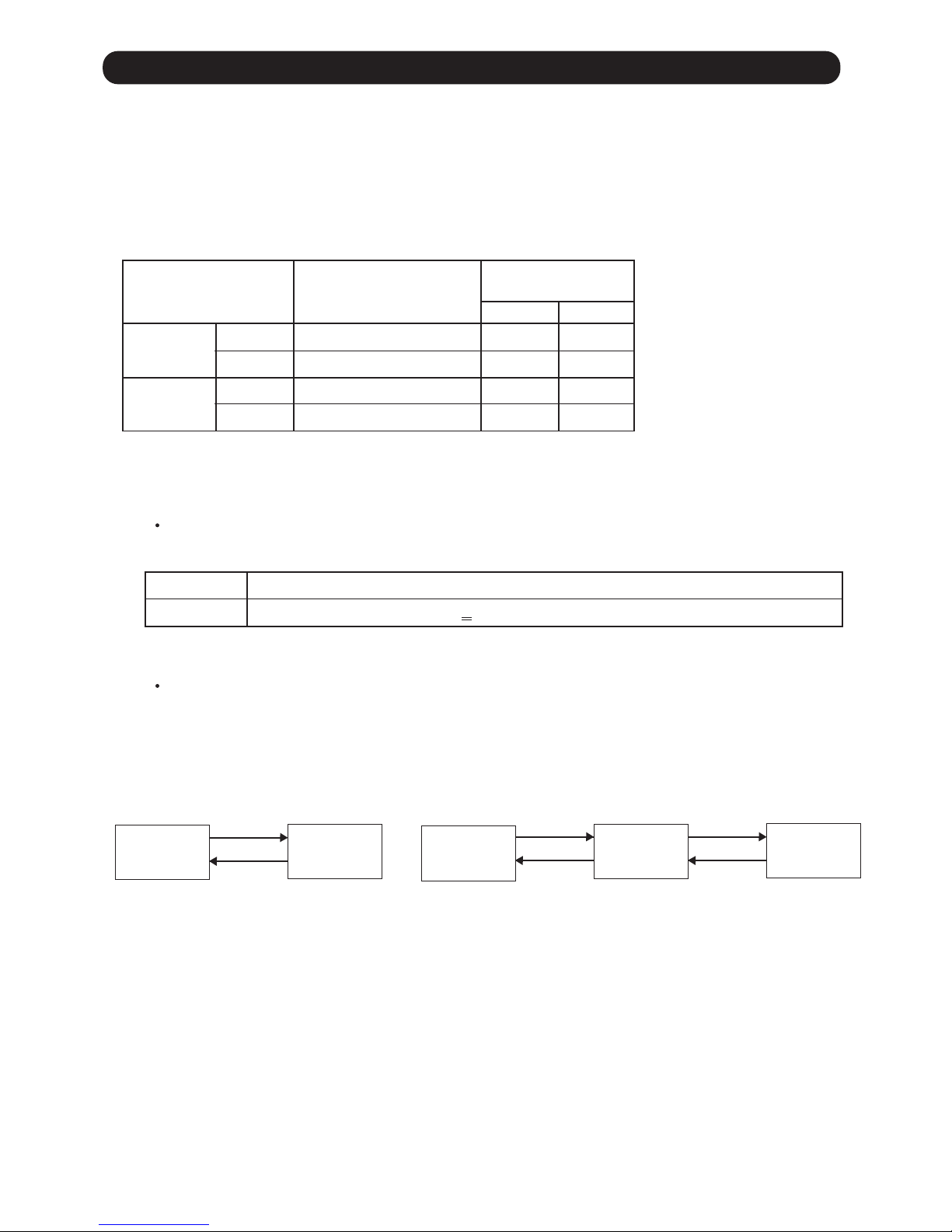
Models Indoor unit Outdoor unit
AUXG30LRLB
AUXG36LRLB
AUXG45LRLB
AUXG54LRLB
AO*G30LBTA
AO*G36LBTA
AO*G45LBTA
INVERTER
SERVICE
INSTRUCTION
R410A
AO*G54LBTA
RCG30LRLB
RCG36LRLB
RCG45LRLB
RCG54LRLB
ROG30LBTA
ROG36LBTA
ROG45LBTA
ROG54LBTA
Page 2

CONTENTS
1. SPECIFICATIONS
1. DESCRIPTION OF EACH CONTROL OPERATION
1-1 COOLING OPERATION............................................................................................
1-4 AUTO CHANGEOVER OPERATION........................................................................
1-5 INDOOR FAN CONTROL.........................................................................................
1-7 OUTDOOR FAN CONTROL
1-6. AIR FLOW DIRECTION CONTROL...................
......................................................................................
...................................................................
1-8 COMPRESSOR CONTROL......................................................................................
01-01
1-2 HEATING OPERATION.............................................................................................
01-02
1-3 DRY OPERATION......................................................................................................
01-03
01-04
01-06
01-09
01-11
01-10
1-9 TIMER OPERATION CONTROL...............................................................................
01-13
1-10 ELECTRONIC EXPANSION VALVE CONTROL......................................................
01-17
1-11 TEST OPERATION CONTROL...............................................................................
01-17
1-12 PREVENT TO START FOR 3 MINUTES (3 MINUTES ST)....................................
01-17
1-13 4-WAY VALVE EXTENSION SELECT....................................................................
01-17
1-14 AUTO RESTART.....................................................................................................
01-18
1-15 PUMP DOWN..........................................................................................................
01-18
1-16 COMPRESSOR PREHEATING...............................................................................
01-20
1-17 10°C HEAT OPERATION........................................................................................
01-20
1-21 VARIOUS PROTECTIONS......................................................................................
01-24
1-22 LOW NOISE OPERATION .......................................................................................
01-27
1-24 HUMAN SENSOR(OPTION) ...................................................................................
01-28
1-20 OFF DEFROST OPERATION CONTROL...............................................................
01-23
1-19 DEFROST OPERATION CONTROL.......................................................................
01-21
1-18 ECONOMY OPERATION........................................................................................
01-20
1-23 PEAK CUT OPERATION .........................................................................................
01-28
1-25 DRAIN PUMP OPERATION............. .........................................................................
01-29
2-1 ERROR DISPLAY......................................................................................................
2. TROUBLE SHOOTING
2-2 TROUBLE SHOOTING WITH ERROR CODE
..........................................................
2-3 TROUBLE SHOOTING WITH NO ERROR CODE
....................................................
2-4 SERVICE PARTS INFORMATION
............................................................................
02-01
02-29
02-03
02-34
1-26 DESCRIPTION OF DISPLAY UNIT .........................................................................
01-30
Page 3

1 . DESCRIPTION OF EACH
CONTROL OPERATION
R410A
INVERTER
Cassette type
Page 4
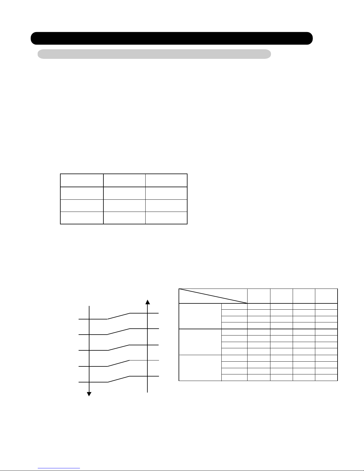
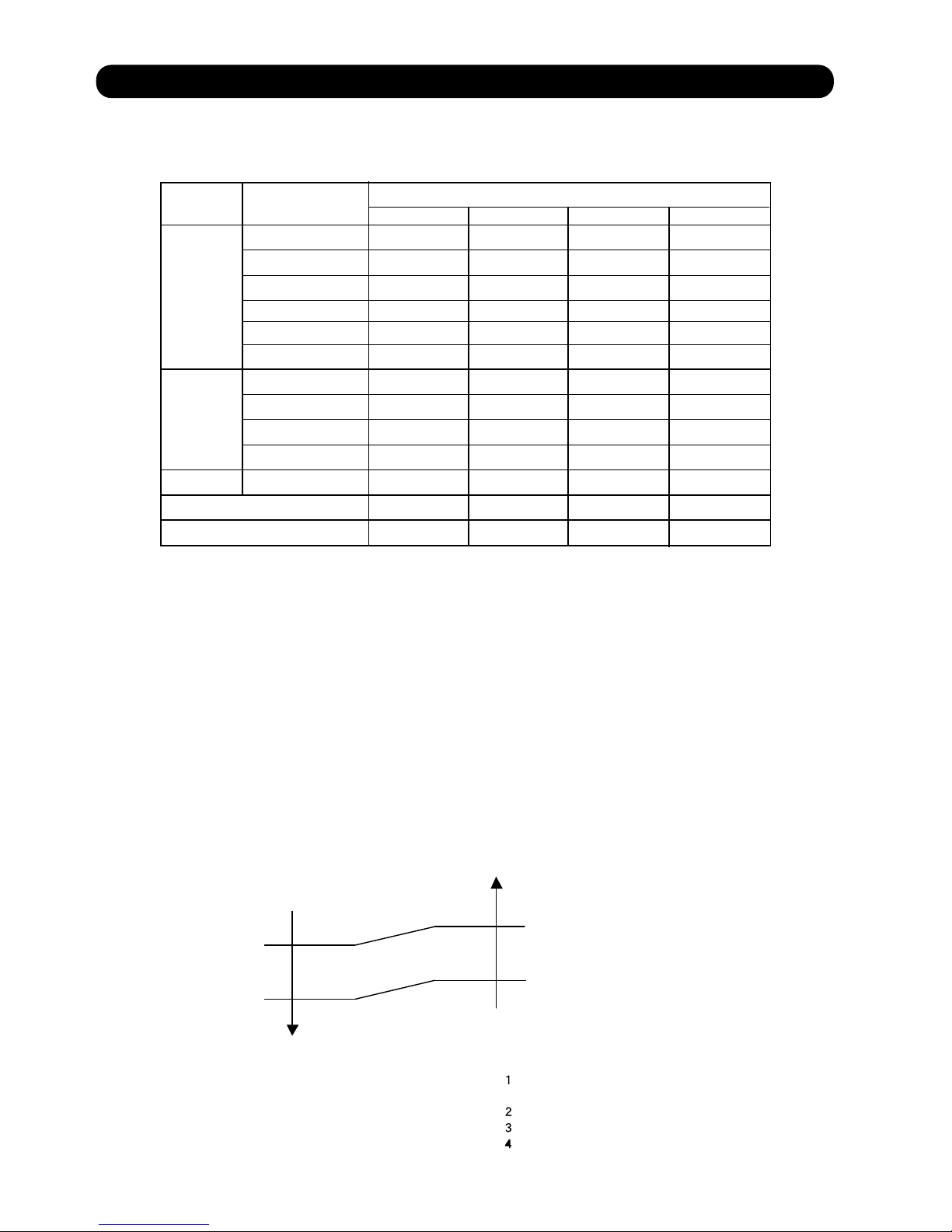
1-1. COOLING OPERATION
1-1-1 COOLING CAPACITY CONTROL
A sensor (room temperature thermistor) built in the indoor unit will usually perceive
difference or variation between a set temperature and present room temperature, and
controls the operation frequency of the compressor.
* If the room temperature is 6.0°C higher than a set temperature,
the compressor operation frequency will attain to maximum performance.
* If the
room temperature is 1.0°C lower than a set temperature, the compressor
will be stopped.
* When the room temperature is between +6.0°C to -1.0°C of the setting temperature,
the compressor frequency is controlled within the range shown in Table1.
However, the maximum frequency is limited in the range shown in Fig.1 based on the
fan speed mode and the outdoor temperature.
minimum
frequency
maximum
frequency
16rps 90rps
30,36LBTA
16rps 100rps
45LBTA
16rps 110rps
54LBTA
Hi Me Lo Qu
72rps
65rps
50rps
44rps 39rps
59rps 50rps
50rps 44rps
35rps
39rps
39rps
A zone
B zone
C zone
D-F zone
30,36LBTA
( Table 1 : Compressor Frequency Range )
( Fig. 1 : Limit of Maximum Frequency based on Outdoor Temperature )
01-01
93rps
93rps
78rps
73rps
56rps 47rps
75rps
75rps
68rps
68rps
68rps 56rps
29rps
44rps
44rps
44rps
A zone
B zone
C zone
D-F zone
Fan speed mode
Outdoor air
temperature
A zone
B zone
C zone
D zone
E zone
F zone
When the room
temperature rises
When the room
temperature drops
36°C
32°C
21°C
12°C
2°C
34°C
30°C
19°C
10°C
0°C
45LBTA
72rps 59rps 50rps 39rps
100rps
100rps
85rps
76rps
62rps 50rps
78rps
78rps
73rps
73rps
73rps 62rps
29rps
44rps
44rps
44rps
A zone
B zone
C zone
D-F zone
54LBTA
Page 5

01-02
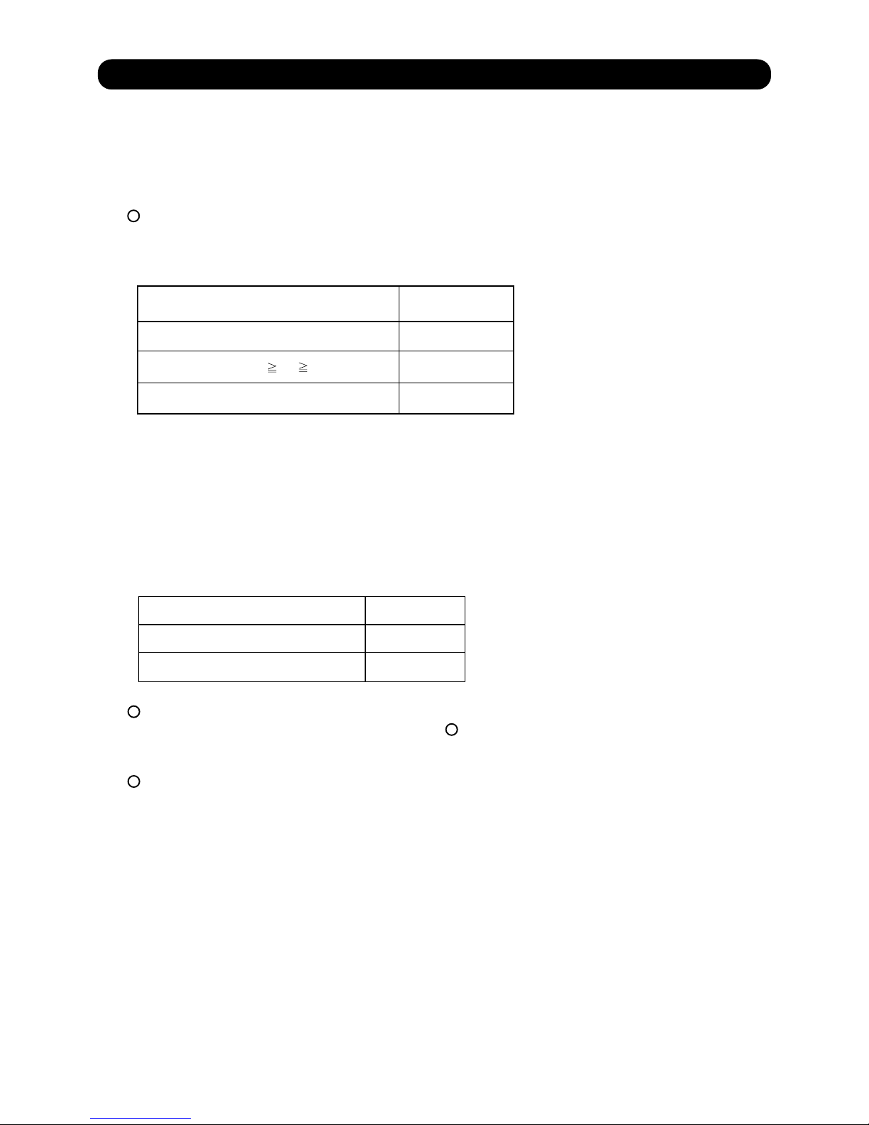
1-2. HEATING OPERATION
A sensor (room temperature thermistor) built in the indoor unit will usually perceive
difference or variation between a set temperature and present room temperature, and
controls the operation frequency of the compressor.
* If the room temperature is lower 6.0°C than a set temperature,
the compressor operation frequency will attain to maximum performance.
* If the room temperature is higher 1.0°C than a set temperature, the compressor
will be stopped.
* When the room temperature is between +1.0°C to -6.0°C of the setting temperature,
the compressor frequency is controlled within the range shown in Table2.
( Table 2 : Compressor Frequency Range )
minimum
frequency
maximum
frequency
16rps 90rps
30,36LBTA
16rps 110rps
45,54LBTA
MODEL
Page 6

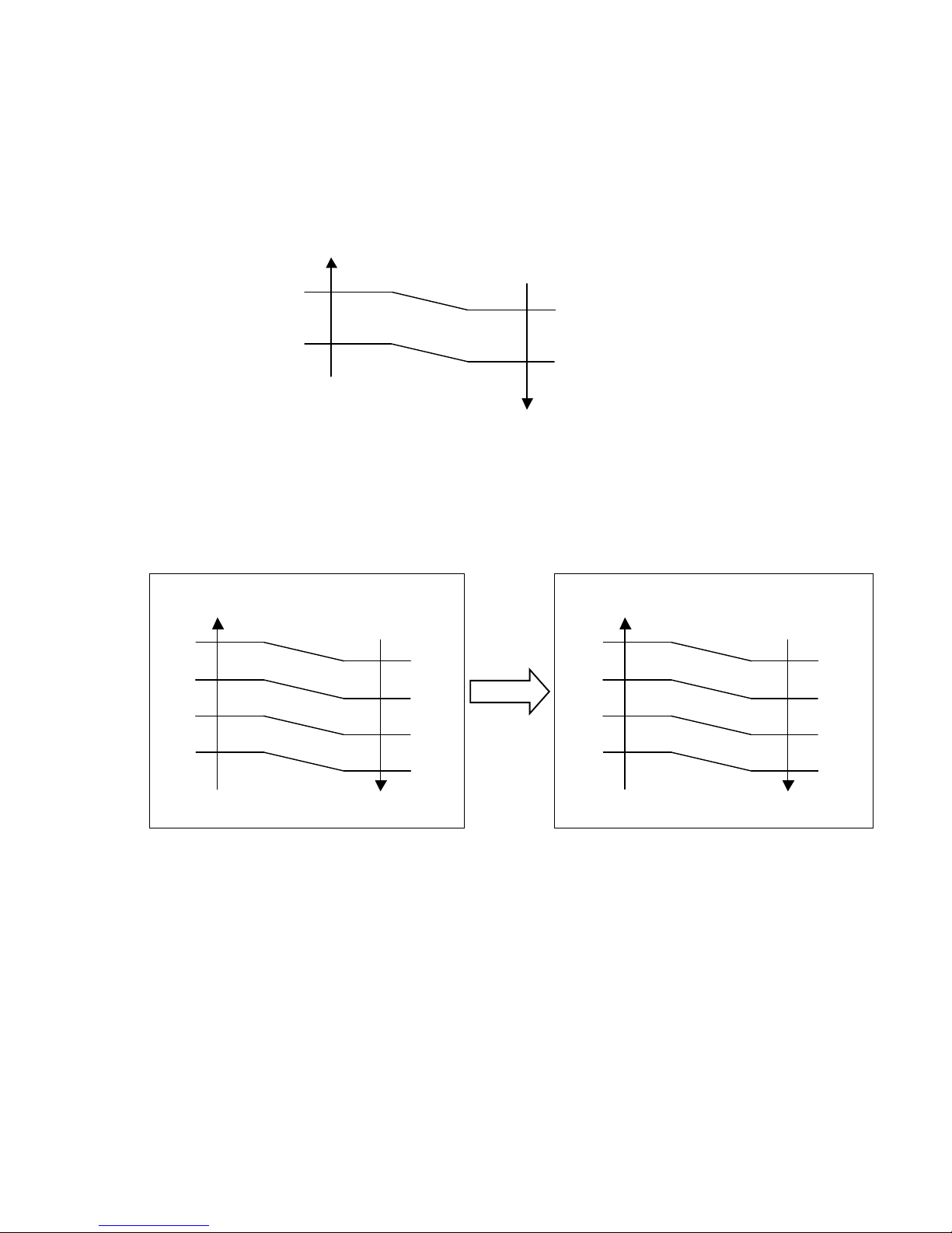
1-3. DRY OPERATION
1-3-1 INDOOR UNIT CONTROL
The compressor rotation frequency shall change according to set temperature and room
temperature variation which the room temperature sensor of the indoor unit has detected
as shown in the Table 3.
( Table 3 : Compressor frequency )
( Fig.2 : Compressor Control based on Room Temperature )
01-03
Ts : Setting temperature
Ts+0.5°C
Ts+1.5°C
Operating frequency
39rps
X zone
J
30,36LRLB
zone
0rps
44rps
0rpsY zone
Room Room
temperature temperature
X zone
J zone
Y zone
Ts-1.5°C
Ts-0.5°C
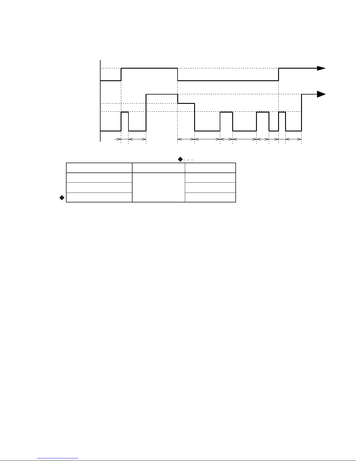
( Fig.3 : Indoor Fan Control )
10 30 60 360 120 360 120 10 30 (sec)
OFF
S-Lo
Lo
OFF
Setting air flow
Compressor
ON
45,54LRLB
Page 7
1-4. AUTO CHANGEOVER OPERATION
01-04
When the air conditioner is set to the Auto mode by remote controller, operation starts in the optimum
mode from among the Heating, Cooling, and Monitoring mode. During operation, the
optimum mode is automatically switched in accordance with temperature changes. The temperature
can be set between 18°C and 30°C in 0.5°C (wireless and 2WIRE remote controller)
Or 1.0°C(3WIRE remote controller) steps.
When operation starts, indoor fan and outdoor fan are operated for around 1 minutes.
Room temperature and outdoor temperature are sensed, and the operation mode is selected
in accordance with the table below. <Monitoring mode>
( Table 4 : Operation mode selection table )
Room temperature (TR)
TR> Ts+2°C
Ts+2°C TR Ts -2°C
*Middle zone
TR < Ts -2°C Heating
When the compressor was stopped for 6 consecutive minutes by the temperature control function
after the Cooling or Heating mode was selected at above, operation is switched
to Monitoring and the operation mode is selected again.
When the middle zone is selected on the predetermining of the operation mode, the operation mode
before the changing to the monitor mode is selected.
1
2
3
1
( Fig.4 : Outdoor temperature zone selection )
Cooling
Operation mode
Temperature
25
°C and over
25°C under
Heating
Cooling
Mode
*If it's Middle zone, operation mode of indoor unit is selected as below.
(1). Same operation mode is selected as outdoor unit.
If outdoor unit is operating in Cooling and Heating mode,
indoor unit will be operated by the same operation mode.
(2). Selected by the outdoor temperature.
If outdoor unit is operating in other than Cooling and Heating mode, indoor unit will be operated
according to the outdoor temperature as below.
TR : Room temperature
Ts : Setting temperature
Page 8
01-05
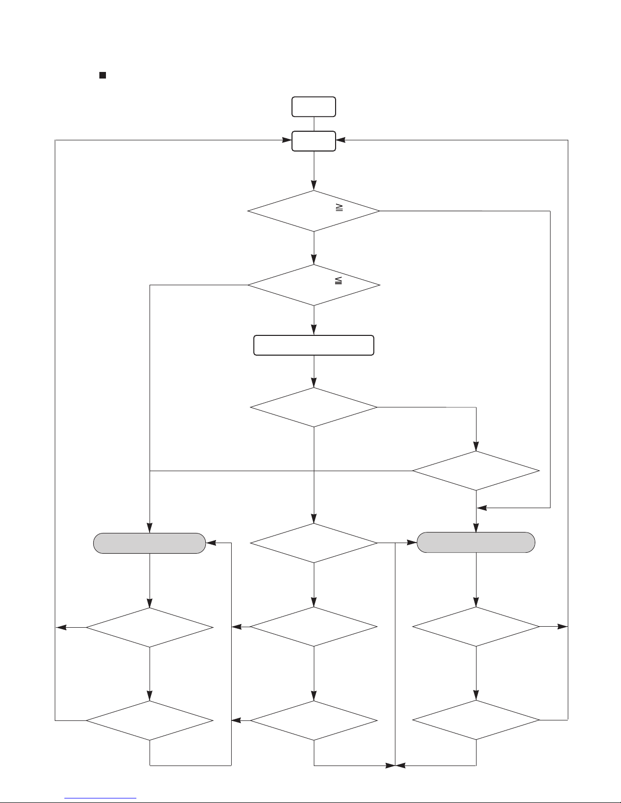
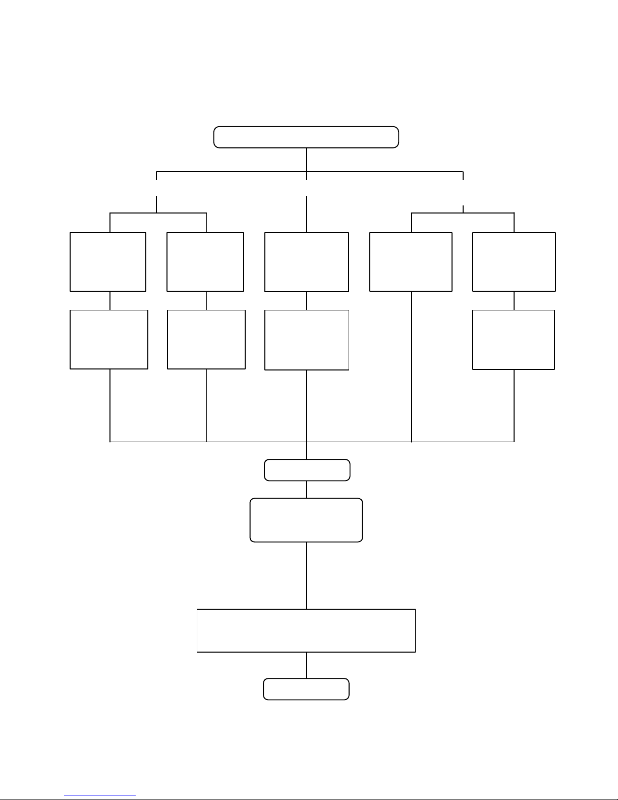
START
Room temp.
Ts+2
°C?
COOLING OPERATIONHEATING OPERATION
YES
Auto change over is
second or more?
NO
NO
YES
NO
NO
AUTO CHANGEOVER operation flow chart
TS : Setting temperature
Room temp.
Ts -2
°C?
Thermostat remains
in OFF state for 6 minutes or
longer?
System stops
or operation command other than
auto changeover operation?
NO
Thermostat remains
in OFF state for 6 minutes or
longer?
System stops
or operation command other than
auto changeover operation?
Middle zone
NO
NO
Operation mode of
outdoor unit : Cooling?
YES
NO
Operation mode of outdoor unit
: Heating?
YES
NO
YES
Outdoor temperature<
25°C?
NO
YES
YES
YES
NO
YES
YES
Operation mode
before the monitor mode is
cooling mode?
Monitor mode
Page 9
1-5. INDOOR FAN CONTROL
1. Fan speed
( Table 5 : Standard of Indoor Fan Speed )
2. FAN OPERATION
*The following fan speed is a standard value.
The airflow can be switched in 5 steps such as AUTO, QUIET, LOW, MED, HIGH, while the indoor
fan only runs.
When [AUTO] is selected, the indoor Fun motor runs MED.
01-06
Operation
mode
Air flow
mode
HIGH
MED+
LOW
Heating
Quiet
Cooling
560
420
300
420
270
470
530
660
430
660
560
510
430
300
430
270
510
600
700
470
700
590
530
470
300
470
270
530
630
HIGH
MED
LOW
Quiet
*Soft Quiet
S-Lo
FAN
Dry
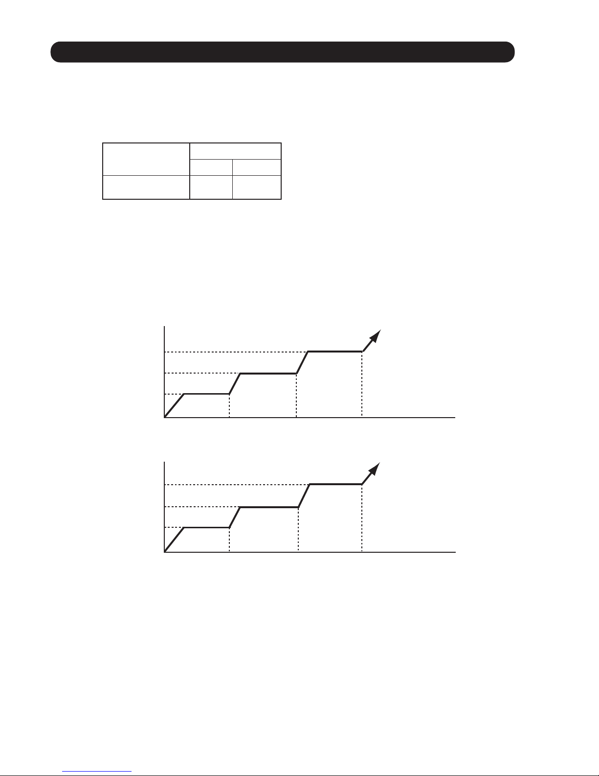
3. COOLING OPERATION
Switch the airflow [AUTO], and the indoor fan motor will run according to a room temperature,
as shown in Fig.5.
On the other hand, if switched in [HIGH] ~ [LOW], the indoor motor will run at a constant airflow of [COOL]
operation modes LOW, MED, HIGH,as shown in Table 5.
( Fig.5 : Airflow change - over ( Cooling : AUTO ) )
When the room
temperature rises
When the room
temperatu
re drops
TR : Room temperature
Ts : Setting temperature
TR-Ts > 2°C
=
1°C > TR-Ts
2°C > TR-Ts > 1°C
=
TR-Ts > 2.5°C
=
1.5°C > TR-Ts
2.5°C > TR-Ts > 1.5°C
=
HIGH mode
MED mode
LOW mode
*1
*1 : Contains a condition to the following
When the operation mode is set to AUTO mode
at the start of operation.
When the setting temperature was changed.
When the operation mode was changed to COOLING mode.
When the airflow mode was changed to AUTO mode.
Speed (rpm)
30LRLB 36LRLB 45LRLB
560
420
470
510
MED
510
560
590
Cool air prevention
300
300 300
54LRLB
740
480
740
630
570
480
300
480
270
570
680
630
300
*Note, during Economy operation and operation mode is FAN, the air flow is 1 step downs.
(Hi > Me, Me > Lo, Lo > Quiet, Quiet > Soft Quiet)
Page 10
4. HEATING OPERATION
Switch the airflow [AUTO], and the indoor fan motor will run according to a room temperature,
as shown in Fig.6.
On the other hand, if switched in [HIGH] ~ [LOW], the indoor motor will run at a constant airflow
of [HEAT] operation modes LOW, MED, HIGH as showin in the Table 5.
6. DRY OPERATION
Refer to the Table 5
During the dry mode operation, the fan speed setting can not be changed.
01-07
Indoor heat exchanger
t
emperature
( Fig.6 : Airflow change - over ( Heating : AUTO ) )
TR-Ts > -1.0°C
=
-2.0°C > TR-Ts
1.0°C > TR-Ts > -2.0°C
=
TR-Ts > -1.5°C
=
-2.5°C > TR-Ts
-1.5°C > TR-Ts > -2.5°C
=
LOW mode
MED mode
HIGH mode
5. COOL AIR PREVENTION CONTROL (Heating mode)
The maximum value of the indoor fan speed is set as shown in Fig.7, based on the detected
temperature by the indoor heat exchanger sensor on heating mode.
When the compressor does not operate, the indoor fan motor operates [S-Lo] or [Stop] mode.
( Fig.7 : Cool Air Prevention Control )
Cool air
prevention
S-Lo
42°C
30°C
34°C
Indoor heat exchanger
temperature rises
Indoor heat exchanger
temperature drops
Hi
*Me+
or setting fan mode
*Lo
or setting fan mode
*Lo
or setting fan mode
*Lo
or setting fan mode
39°C
37°C
37°C
32°C
24°C
*Lower speed is selected.
42°C
30°C
34°C
Indoor heat exchanger
temperature rises
Indoor heat exchanger
temperature drops
Hi
*Me+
or setting fan mode
*Lo
or setting fan mode
39°C
37°C
37°C
32°C
24°C
*Lower speed is selected.
13 min. later
Page 11
01-08
Compressor
ON
OFF
Indoor fan
Setting air flow
OFF
10 30 60 180 60 180 60 10 30
(sec)
S-Lo
480rpm
( Fig 8 : Indoor Fan Control)
7. FAN CONTROL FOR ENERGY SAVING
When the air flow setting except AUTO mode, the indoor fan motor will run as shown in Fig.8.
( Factory setting)
Setting Description Function Number Setting Value
Disable
Enable
Remote controller
49
02
00
01
00 : When the outdoor unit is stopped, the indoor unit fan operates continuously following
the setting on the remote controller.
01 : When the outdoor unit is stopped, the indoor unit fan operates intermittently at a very
low speed.
02 : Enable or disable this function by remote controller setting.
Set to “00”or “01”when connecting a remote controller that cannot set
the Fan control for energy saving function or connecting a network converter.
To confirm if the remote controller has this setting,
refer to the operating manual of each remote controller.
8. DEFROST OPERATION
When the defrost operation starts, the indoor fan runs according to cool air prevention control for 20 seconds.
And the fan is stopped if 20 seconds have passed.
When 60 seconds have passed after defrost operation is released,
the fan runs according to cool air prevention control.
Page 12

To independently can be set the airflow pattern of each louver as this image.
Individual control
All louver control
This function is given priority to overall louver control.
But this function is release during the following operation.
Cold air prevention control
Monitor mode on the auto change over operation
Defrost operation
*When the 2 wire remote controller is disconnected, clear the individual setting.
Otherwise, this setting can’t change.
All louver operation
*Setting of the wireless remote controller is not displayed on the wired remote controller.
*The setting louver of the individual control function cannot be controlled.
Cooling mode standard position: 2
Dry mode standard position: 2
When the mode is selected, the standard
louver position of the each mode is set.
Monitor mode position: 2
Heating standard position Model 30,36 : 4 / Model 45,54 : 3
The air direction range will change as follows:
Use the wired remote controller to set this function.
This function is only available by 2 wire remote controller.
(Fig.11 : Air Direction Range)
(Fig.10 : Independent louver control image)
01-09
1-6. AIR FLOW DIRECTION CONTROL
Page 13

1-7. OUTDOOR FAN CONTROL
1. Outdoor Fan Motor
Following table shows the fan speed of the outdoor unit.
*
The outdoor fan speed changes in the range mentioned above depending on the compressor
frequency and outdoor temperature.
(When the compressor frequency and outdoor temperature increase, the outdoor fan speed
also changes to the higher speed.
When the compressor frequency and outdoor temperature decrease, the outdoor fan
speed also changes to the lower speed.)
*
It runs at 500rpm for 20 seconds after starting up the outdoor fan.
However, the fan operates at 200rpm when the initial rotation speed is 300rpm or less.
01-10
( Table 6 : Fan speed of the outdoor unit )
900/ 800/ 620/ 550/ 500/ 450/ 400/
320/ 300/ 250/ 200
900/ 850/ 800/ 620/ 550/ 450
900/ 850/ 800/ 620/ 550/ 450
850/ 800/ 620/ 550/ 500/ 450/ 400/
320/ 300/ 250/ 200
Cooling
Heating
30LBTA
850(800)/ 780(750)/ 750(700)/ 540(520)/
360(340)/ 290(270)/ 480(0)/ 400(0)/
350(0)/ 280(0)
Upper fan(Lower fan)
45,54LBTA
After operating the defrost control function on heating mode except economy operation,
its speed becomes 900 (Lower:880) rpm regardless of the compressor speed.
However, it returns to the normal speed control when the defrosting operation does not function
for 240 minutes after releasing the defrost operation or when the outdoor temperature sensor
detection value becomes higher than 5
*
The compressor and the fan start-up at the same time, and the fan stops after the compressor
stops and 60 seconds has passed.
*
The fan doesn't operates fan 10 seconds after the fan stops.
*
36LBTA
900(880)/ 850(830)/ 780(750)/ 720(700)/
570(550)/ 500(480)/ 370(350)/ 300(280)/
220(200)
rpm
°C.
MODEL
Page 14
1-8. COMPRESSOR CONTROL
2. OPERATION FREQUENCY CONTROL AT START UP
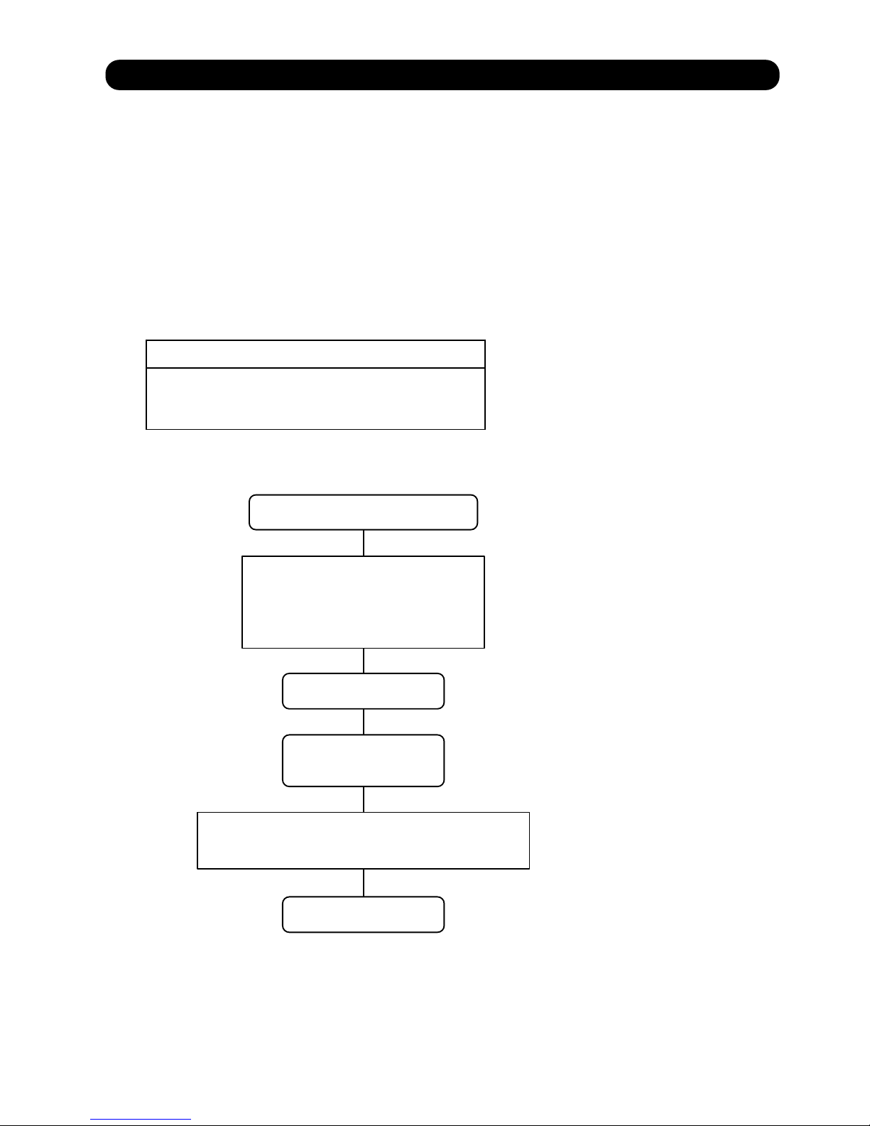
The compressor frequency soon after the start-up is controlled as shown in Fig.9.
(Fig.9 : Compressor Control at Start-up)
30
60
47
60
120 180
(rps)
Upper
limit
speed
(sec)Elapsed time
30
60
47
60
180
(rps)
Upper
limit
speed
(sec)Elapsed time
< Normal start-up Coolling/ Dry >
<Immediate start-up after power-ON / Heating>
240
30,36LBTA
1. OPERATION FREQUENCY RANGE
The operation frequency of the compressor is different based on the operation mode as
shown in Table 7.
Coolin/Dry/Heating
Min
Max
(Table 7 : Compressor Operation Frequency Range)
30,36LBTA
16rps 90rps
01-11
MODEL
Page 15

01-12
Upper
limit
speed
Elapsed time
Elapsed time
Ta : Outdoor temperature
Tc : Compressor temperature
< Normal start-up >
90
39
57
68
85
180 420 480
(sec)
(rps)
Condition
Mode: Cooling
Mode: Heating
Tc > 15
Below 3 hours from comp stop
°C
Mode: Heating
Ta > 10
Below 3 hours from comp stop
3 hours longer from comp stop
°C
Ta > 10
°C
3 hours longer from comp stop
Ta < 10
°C
Tc < 15
°C
Mode: Heating
Ta < 10
Below 3 hours from comp stop
°C
Tc < 15
°C
Upper
limit
speed
200 700 840 1,010
(sec)
(rps)
39
57
68
85
Condition
Condition
=
=
=
Upper
limit
speed
90 210 270 300
(sec)
(rps)
39
57
68
85
1. OPERATION FREQUENCY RANGE
The operation frequency of the compressor is different based on the operation mode
shown in Table 8.
Cooling i gnitaeH
Min Max
Min Max
(Table 8 : Compressor Operation Frequency Range)
16rps 100rps 45LBTA
54LBTA
16rps 110rps
16rps 110rps 16rps 110rps
2. OPERATION FREQUENCY CONTROL AT START UP
The compressor frequency soon after the start-up is controlled as shown in Fig.10.
(Fig.10 : Compressor Control at Start-up)
45,54LBTA
< Immediate / under specific conditions start-up>
MODEL
Page 16
1-9. TIMER OPERATION CONTROL
1. ON / OFF TIMER
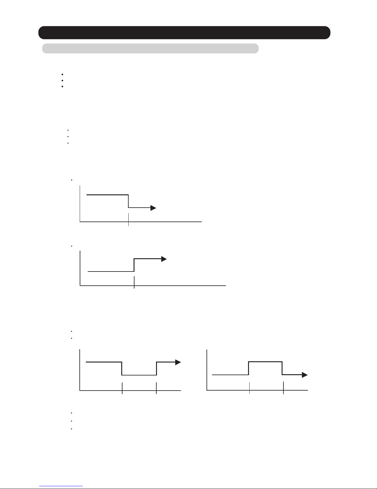
OFF timer : When the clock reaches the set time, the air conditioner will be turned off.
Operation mode
Stop mode
Set time of timer
ON timer : When the clock reaches the set time, the air conditioner will be turned on.
Operation mode
Stop mode
Set time of timer
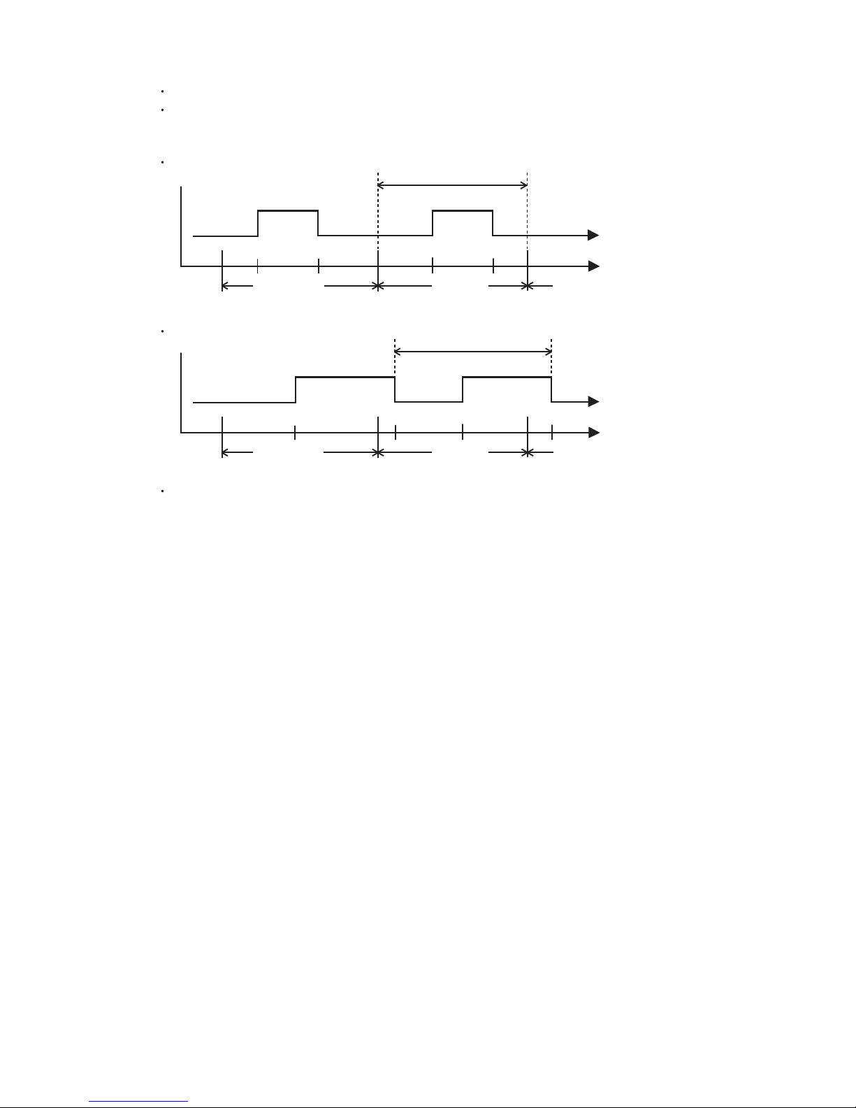
The weekly timer allows up to two ON and OFF time to set up per day.
Use this timer function to set operating time for each day of the week.
Operation mode
The operating time can be set in 30 min increments only.
The OFF time can be carried over to next day.
The ON timer and the OFF timer functions cannot be set with using the weekly timer.
Both ON and OFF time must be set.
2. WEEKLY TIMER
2-1. WEEKLY TIMER
Stop mode
Stop mode
Stop mode
Operation mode
Operation mode
Set time
Set time Set time Set time
01-13
UTY-RNR*Z1(2 wire remote controller)
1-9-1 Wired Remote Controller
ON / TIMER
*3 wire remote controller can be connected
If 3 wire remote controller is connected, set the DIP-SW on the controller PCB
Refer to the installation manual for detailed.
Sleep timer
Timer
10°C heat operation
If used in combination with wireless and wired remote controller, the following function is limited.
OFF / TIMER
WEEKLY TIMER
Page 17
01-14
The DAY OFF setting is only available for days for which weekly settings already exist.
The DAY OFF setting can only be set one time. The DAY OFF setting is cancelled automatically
after the set day has passed.
Normal
Next day setting
If the operating time carries over to the next day (during a next day setting), the effective
DAY OFF range will be set as shown below.
2-2. DAY OFF setting
Stop mode
Stop mode
Operation mode
Stop mode
Operation mode
Preceding day Next day
DAY OFF
Stop mode
Stop mode
Operation mode
Stop mode
Operation mode
DAY OFF
Setting day
Preceding day Next daySetting day
Page 18
01-15
AR- REJ1E
1. ON / OFF TIMER
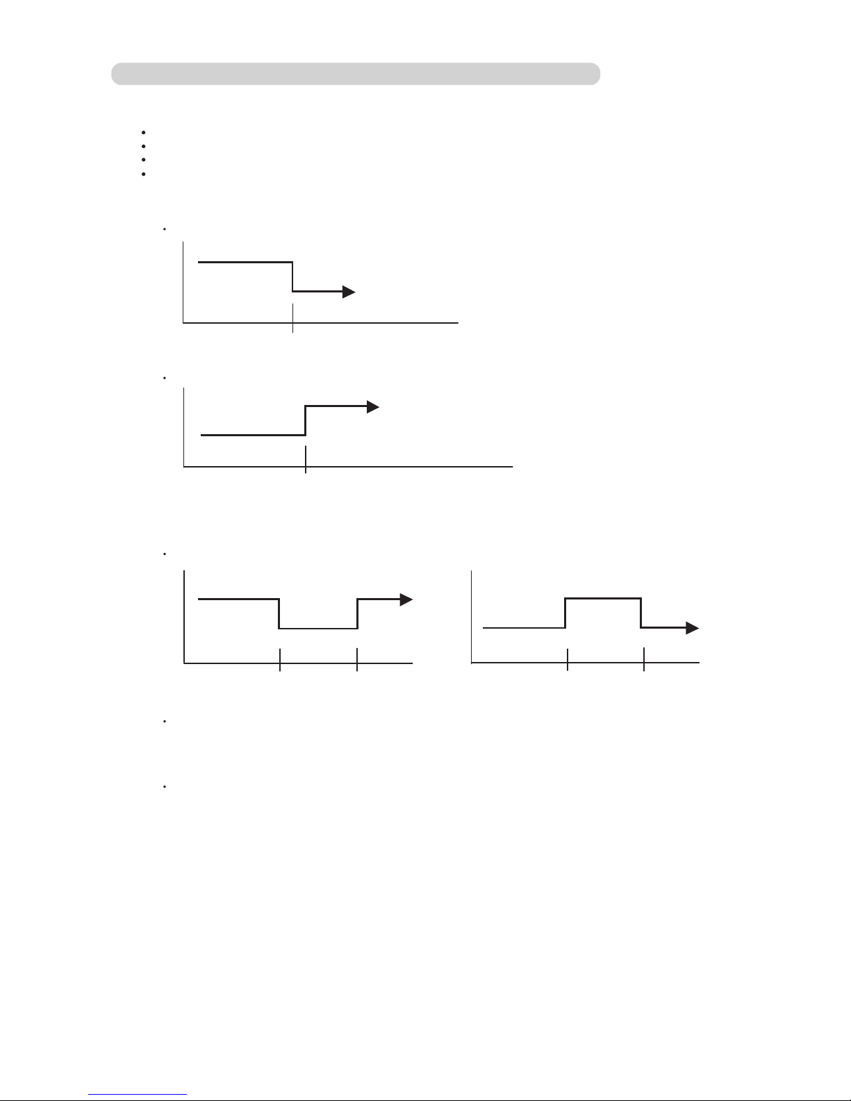
OFF timer : When the clock reaches the set time, the air conditioner will be turned off.
Operation mode
Stop mode
Set time of timer
ON timer : When the clock reaches the set time, the air conditioner will be turned on.
Operation mode
Stop mode
Set time of timer
2. PROGRAM TIMER
ON / TIMER
OFF / TIMER
PROGRAM TIMER
SLEEP TIMER
The program timer allows the OFF timer and ON timer to be used in combination one time.
Operation mode
Operation will start from the timer setting (either OFF timer or ON timer)
whichever is closest to the clock's current timer setting.
The order of operations is indicated by the arrow in the remote control unit's display.
SLEEP timer operation cannot be combined with ON timer operation.
Stop mode
Stop mode
Stop mode
Operation mode
Operation mode
Set time
Set time Set time Set time
1-9-2 Wireless Remote Controller (OPTION)
Page 19
01-16
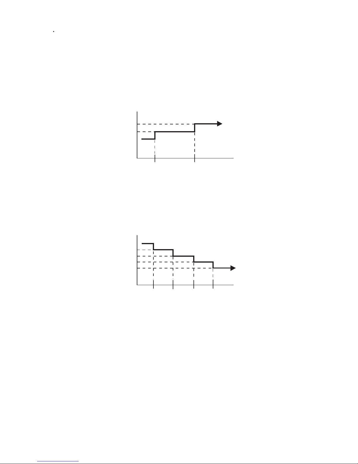
3. SLEEP TIMER
If the sleep timer is set, the room temperature is monitored and the operation is stopped automatically.
If the operation mode or the set temperature is change after the sleep timer is set, the operation is
continued according to the changed setting of the sleep timer from that time ON.
Set temperature rises
( Ts : Set temperature )
Stop of operation
Set temperature lowers
( Ts : Set temperature )
Ts
Stop of operation
In the COOLING operation mode
When the sleep timer is set, the setting temperature is increased 1 degC.
It increases the setting temperature another 1 degC after 1 hour.
After that, the setting temperature is not changed and the operation is stopped at the time
of timer setting.
Ts
+1°C
+2°C
-2°C
-1°C
-4°C
-3°C
Set
60min
In the HEATING operation mode
When the sleep timer is set, the setting temperature is decreased 1 degC.
It decreases the setting temperature another 1 degC every 30 minutes.
Upon lowering 4 degC, the setting temperature is not changed and the operation stops
at the time of timer setting.
Set
30min
60min
90min
Page 20
1-10. ELECTRONIC EXPANSION VALVE CONTROL
The most proper opening of the electronic expansion valve is calculated and controlled under the
present operating condition based on the following values.
The compressor frequency, the temperatures detected by the discharge temperature sensor
and the outdoor temperature sensor.
The pulse range of the electronic expansion valve control is
53 ~ 480 pulses (Cooling) and 40 ~ 480 pulses (Heating).
The pulse range of the electronic expansion valve control is
53 ~ 480 pulses (Cooling) and 53 ~ 480 pulses (Heating).
At the time of supplying the power to the outdoor unit, the initialization of the electroni
c
expansion valve is operated (528 pulses are input to the closing direction).
The compressor won't enter operation status for 3 minutes after the compressor is stopped,
even if any operation is given.
At the time when the air conditioner is switched from the cooling mode to heating mode,
the compressor is stopped, and the 4-way valve is switched in 3 minutes later
after the compressor stopped.
1-12. PREVENT TO RESTART FOR 3 MINUTES ( 3 MINUTES ST )
1-13. 4-WAY VALVE EXTENSION SELECT
01-17
30,36LBTA
45,54LBTA
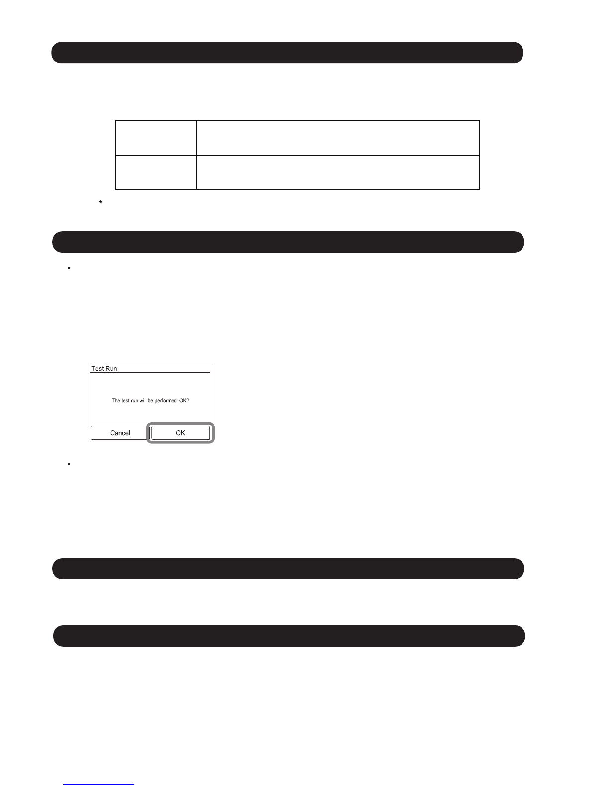
1-11. TEST OPERATION CONTROL
Touch the [Test run] in the “Maintenance” screen.
The “Test Run” screen is displayed.
Touch [OK] to return to the Maintenance screen, and start the test run.
The test run will automatically end is approximately 60 min.
If you wish to cancel the test run before it is complete, return to the “Monitor Mode screen”, and touch
the On/Off button.
(Installer password* is required.)
*If the password has been changed from the default setting “0000”,
please contact the installer.
With Wired Remote Controller
Under the condition where the air conditioner runs, press the TEST RUN button, and
the test operation control mode will appear.
During test running, the Operation LED and Timer LED of the air conditioner body blinks simultaneously.
Set the test operation mode, and the compressor will continue to run regardless of whether the room
temperature sensor detects.
The test operation mode is released if 60 minutes have passed after setting up the test operation.
With Wireless Remote Controller
Page 21

01-18
1-15. PUMP DOWN For Model 30,36
When the power was interrupted by a power failure, etc. during operation, the operation contents
at that time are memorized and when power is recovered, operation is automatically resumed with
the memorized operation contents.
When the power is interrupted and recovered during timer operation, timer operation is canceled,
but only setting time is memorized.
[Operation contents memorized when the power is interrupted]
Operation mode
Air flow direction (Swing setting)
Individual air flow direction (Swing setting)
Human sensor auto saving (setting/timer)
Human sensor auto off (setting/timer)
Energy saving setting
Set temperature
Set air flow
Timer mode and timer time (Set by wireless remote controller)
10°C HEAT (Wireless remote controller is in use)
Each central setting
ECONOMY
1-14. AUTO RESTART
Page 22
1-15. PUMP DOWN For Model 45,54
01-19
WARNING
Never touch electrical components such as the terminal blocks except the button on
the display board. It may cause a serious accident such as electric shock.
During the pump-down operation, make sure that the compressor is turned off
before you remove the refrigerant piping.
Do not remove the connection pipe while the compressor is in operation with 2-way
or 3-way valve open. This may cause abnormal pressure in the refrigeration cycle
that leads to breakage and even injury.
CAUTION
Perform the pump down operation before disconnecting any refrigerant pipe or
electric cable.
Collect refrigerant from the service port or the 3-way valve if pump down cannot be
performed.
In case of a group control system installation, do not turn the power off pump down is
completed in all outdoor units.
(Group control system installation described in “SPECIAL INSTALLATION
METHODS” in the installation manual of the indoor unit.)
Please check the refrigerant circuit for any leaks before starting the pump down
operation.
Do not proceed with the pump down operation if there is no refrigerant left in the
circuit due to bent or broken piping.
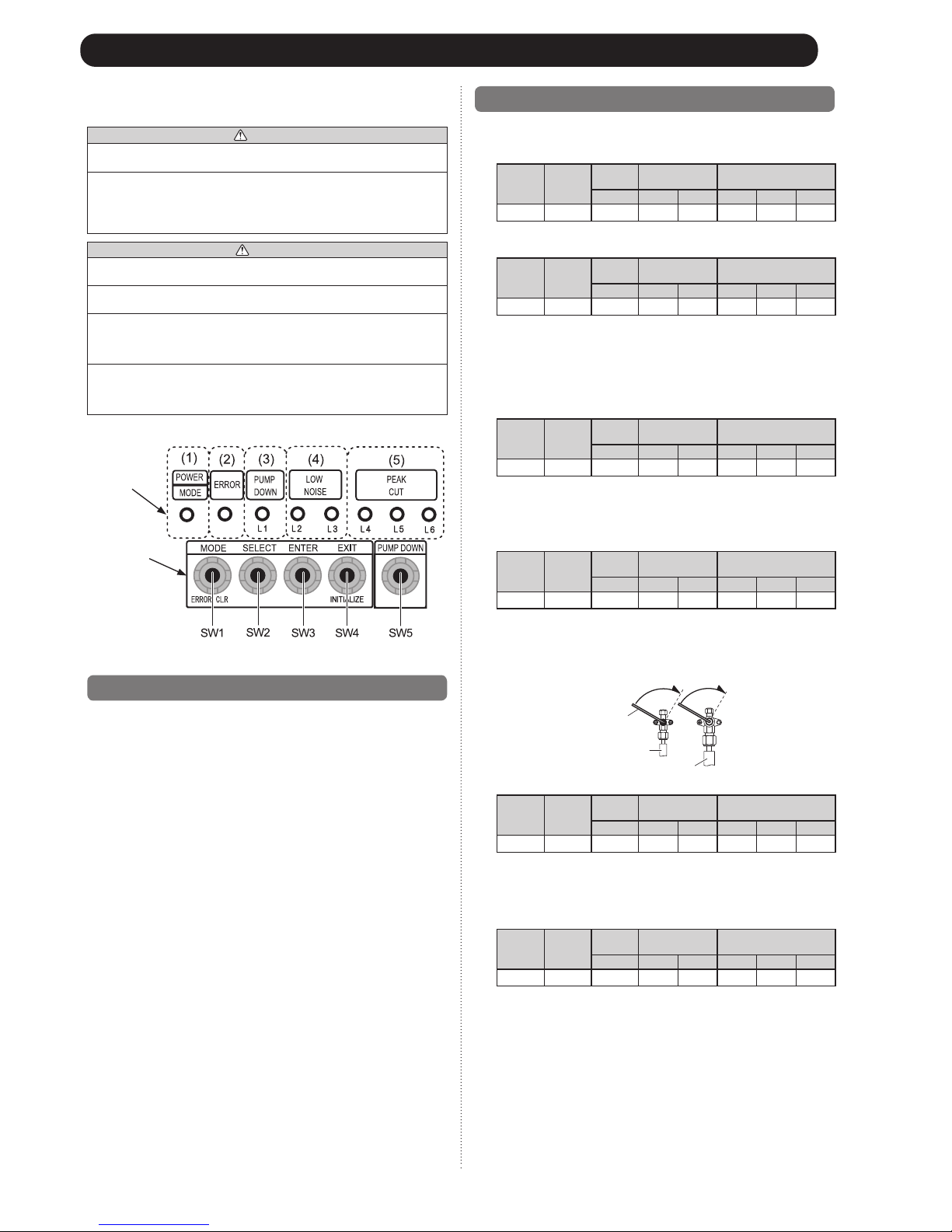
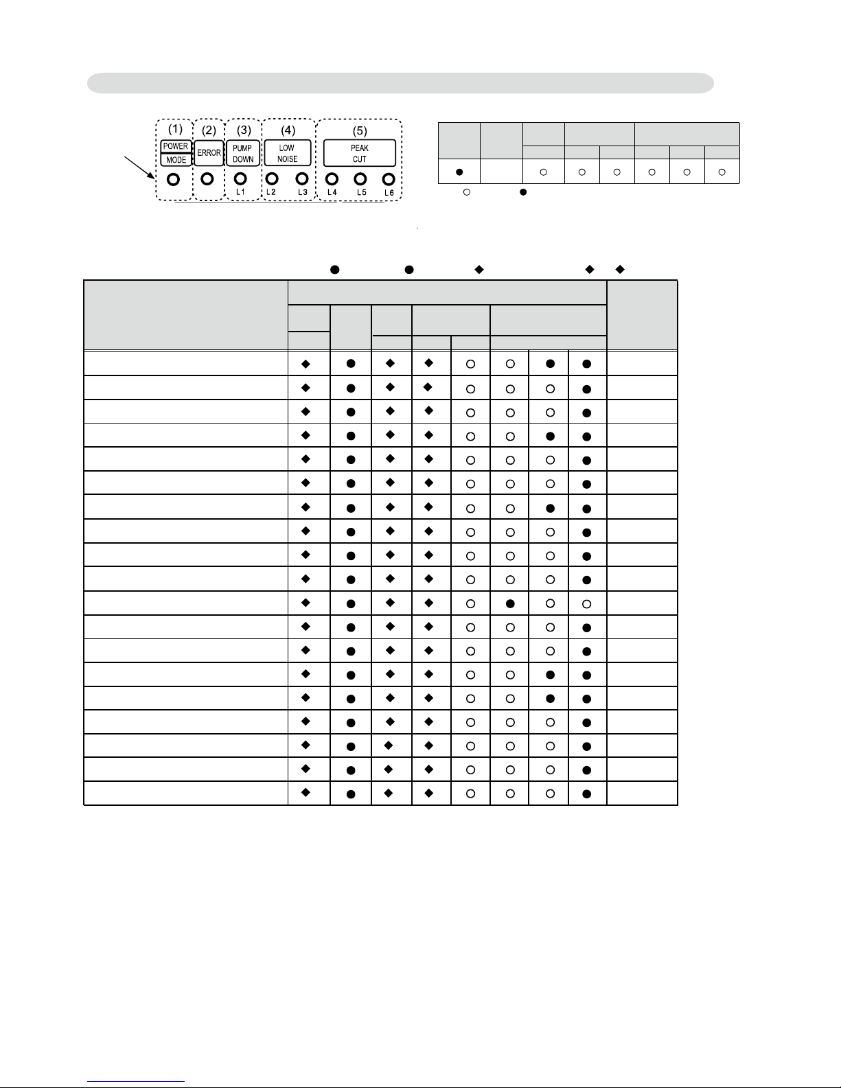
Operate “PUMP DOWN” • button on the display board in the manner described
below.
LED display part
Button part
14.1. Preparation for pump down
Confirm that the power is off, and then open the service panel.•
14.2. Pump down procedure
(1) Check the 3-way valves (both the liquid side and gas side) are opened.
(2) Turn the power on.
POWER/
MODE
ERROR
PUMP
DOWN
LOW
NOISE
PEAK
CUT
(L1) (L2) (L3) (L4) (L5) (L6)
●○○ ○○○○○
Sign “○”: Lights off, “●”: Lights on
(3) Press “PUMP DOWN” button for 3 seconds or more after 3 minutes after power on.
POWER/
MODE
ERROR
PUMP
DOWN
LOW
NOISE
PEAK
CUT
(L1) (L2) (L3) (L4) (L5) (L6)
●○● ○○●●●
Sign “○”: Lights off, “●”: Lights on
LED display lights on as shown in the above figure, and the fans and the
compressor start operating.
eht ,gnitarepo si rosserpmoc eht elihw desserp si nottub ”NWOD PMUP“ • eht fI
compressor will stop, then start again in about 3 minutes.
(4) LED display will change as shown below about 3 minutes after the compressor
starts. Fully close the 3-way valve on the liquid pipe side at this stage.
POWER/
MODE
ERROR
PUMP
DOWN
LOW
NOISE
PEAK
CUT
(L1) (L2) (L3) (L4) (L5) (L6)
●○● ○○○●●
Sign “○”: Lights off, “●”: Lights on
If the valve on the liquid pipe side is not closed, the pump down cannot be •
performed.
(5) When LED display changes as shown in the below figure, close the 3-way valve on
the gas pipe side tightly.
POWER/
MODE
ERROR
PUMP
DOWN
LOW
NOISE
PEAK
CUT
(L1) (L2) (L3) (L4) (L5) (L6)
●○● ○○○○●
Sign “○”: Lights off, “●”: Lights on
If the valve on the gas pipe side is not closed, refrigerant may flow into the piping •
after the compressor stops.
Step (5)
Closing direction
Step (4)
Hexagon wrench
Liquid pipe
Gas pipe
Closing direction
(6) LED display changes after 1 minute as shown in the figure below.
POWER/
MODE
ERROR
PUMP
DOWN
LOW
NOISE
PEAK
CUT
(L1) (L2) (L3) (L4) (L5) (L6)
●○● ○○○○○
Sign “○”: Lights off, “●”: Lights on
Fans and compressor stop automatically.
If the pump down is successfully completed (the above LED display is shown), the •
outdoor unit remains stopped until the power is turned off.
(7) Turn the power off.
POWER/
MODE
ERROR
PUMP
DOWN
LOW
NOISE
PEAK
CUT
(L1) (L2) (L3) (L4) (L5) (L6)
○○○ ○○○○○
Sign “○”: Lights off
PUMP DOWN is completed.
(Note)
To stop pump down, press the “PUMP DOWN” button again.•
To start the pump down again after the compressor is automatically stopped due to an •
error, turn the power off and open the 3-way valves. Wait 3 minutes, turn the power on
and start the pump down again.
When starting the operation after completion of the pump down, turn the power off, •
and then open the 3-way valves. Wait 3 minutes, turn the power on and perform a test
run in the “COOL” operation mode.
If an error occurs, recover the refrigerant from service port.•
Page 23
1-16. COMPRESSOR PREHEATING
When the outdoor temperature is lower than 20°C and the all operation mode has been
stopped for 30 minutes, power is applied to the compressor and the compressor is heated.
(By heating the compressor, warm air is quickly discharged when operation is started.)
When operation was started and when the outdoor temperature rises to 26°C or greater,
preheating is ended.
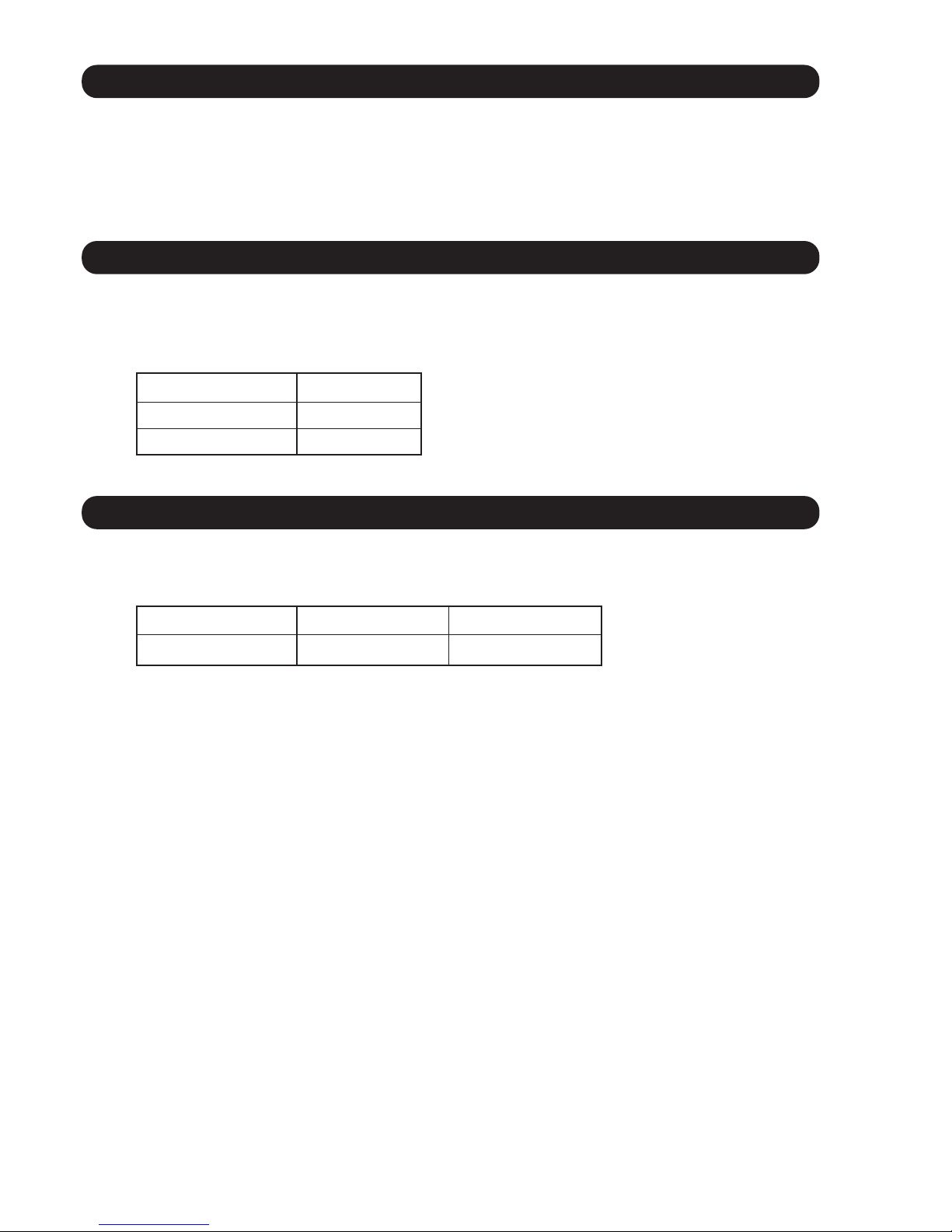
1-17. 10°C HEAT OPERATION
The 10°C HEAT operation
The 10°C HEAT
The 10°C HEAT
operation can be set by the wireless remote controller.
functions by pressing 10°C HEAT button on the remote controller.
operation is almost the same operation as below settings.
Mode Heating
Setting temperature 10°C
Fan mode AUTO
( Table9 )
1-18. ECONOMY OPERATION
The ECONOMY operation functions by pressing ECONOMY button on the remote controller.
The ECONOMY operation is almost the same operation as below settings.
Mode Cooling/ Dry Heating
Target temperature Setting temp.+1°C Setting temp.-1°C
( Table10)
01-20
Page 24
1-19. DEFROST OPERATION CONTROL
1. CONDITION OF STARTING THE DEFROST OPERATION
Integratingdefrost
(Constant monitoring)
If the compressor continuous operation time is less than 10 minutes,
the OFF number of the compressor is counted.
If any defrost operated, the compressor OFF count is cleared.
2. CONDITION OF THE DEFROST OPERATION COMPLETION
Defrost operation is released when the conditions becomes as shown in Table 14.
( Table 14 : Condition of defrost release )
Release Condition
Outdoor heat exchanger temp. is higher than 12°C
or
Compressor operation time has passed 15 minutes.
The defrost operation starts as shown in the following Table 11, 12, and 13.
From 2nd and later
defrost after
starting operation
Less than 35 minutes More than 35 minutes
Does not operate
Compressor integrating operation time
( Table 11 : Condition of 1st defrost operation)
1st defrost
after
starting operation
Compressor integrating operation time
Less than 22 minutes More than 22 minutes More than 62 minutes
Does not operate
Outdoor heat exchanger temp.
Below -9°C
Outdoor heat exchanger temp.
Below -10°C
Outdoor heat exchanger temp.
Below -5°C
More than 240 minutes
( For long continuous operation )
Less than 10 minutes
( For
intermittent operation )
Compressor integrating operation time
Outdoor heat exchanger temp.
Below -3°C
OFF count of the compressor
40 times
( Table 13 : Condition of Integrating defrost operation)
( Table 12 : Condition of 2nd defrost operation)
01-21
Page 25
01-22
3. Defrost Flow Chart
The defrosting shall proceed by the integrating operation time, outdoor temperature
and outdoor heat exchanger temperature as follows.
(Not defrosted for 10 minutes)
Heating operation start : Compressor ON
Outdoor heat exchanger temp.: Over 12°C
or
Compressor ON time: Maximum 15 minutes
Defrost end
Compressor
integrating
operation:
Over 22 minutes
Compressor
integrating
operation:
Over 62 minutes
Outdoor
heat exchanger
temp.:
Below - 9°C
Outdoor
heat exchanger
temp.:
Below - 5°C
Compressor
integrating
operation:
Over 35 minutes
2nd and later defrost
Compressor : OFF
Outdoor fan motor : OFF
30 sec later 4-way valve : OFF
36 sec later compressor : ON
Compressor
integrating
operation:
Over 240 minutes
Integrating defrost
(Constant monitoring)
Defrost Indicator:
[Operation lamp]
7 sec ON / 2 sec OFF
Defrost start
Outdoor
heat exchanger
temp.:
Below - 10°C
Outdoor
heat exchanger
temp.:
Below - 3°C
Compressor
OFF count :
40 times
1st defrost
Page 26
1-20. OFF DEFROST OPEARTION CONTROL
01-23
1. OFF DEFROST OPERATION CONDITION
When operation stops in the [Heating operation] mode, if frost is adhered to the outdoor unit heat
exchanger, the defrost operation will proceed automatically. In this time, if indoor unit operation
lamp flashes slowly (7 sec ON / 2 sec OFF), the outdoor unit will allow the heat exchanger to defrost,
and then stop.
In heating o
peration, the outdoor heat exchanger temperature is less than -4°C, and
compressor operation integrating time lasts for more than 30 minutes.
OFF Defrost Flow Chart
Heating operation stop
Outdoor heat exchanger temp. :
Below -4°C
and
Compressor integrating operation :
Over 30 minutes
Defrost start
Defrost Indicator:
[Operation lamp]
7 sec ON / 2 sec OFF
Outdoor heat exchanger temp. : Over 12°C
or
Compressor ON time : Maximum 15 minutes
Defrost end
2. OFF DEFROST RELEASE CONDITION
Release Condition
Outdoor heat exchanger temp. is higher than 12°C
or
Compressor operation time has passed 15 minutes.
( Table 15 : OFF Defrost Release Condition )
OFF defrost operation is released when the conditions becomes as shown in Table 15.
Page 27
1-21. VARIOUS PROTECTIONS
1. DISCHARGE GAS TEMPERATURE OVERRISE PREVENTION CONTROL
The discharge gas thermosensor (discharge thermistor : Outdoor side) will detect discharge gas
temperature.
When the discharge temperature becomes higher than Temperature ,the compressor frequency
is decreased 10rps(30,36) 14rps(45,54), and it continues to decrease the frequency for 10/14rps every
120 seconds until
the temperature becomes lowe
r than Temperature .
When the discharge temperature becomes lower than Temperature , the control of
the compressor frequency is released.
When the discharge temperature becomes higher than Temperature ,the compressor is stopped
and the indoor unit LED starts blinking.
(Table16 : Discharge Temperature Over Rise Prevention Control / Release Temperature)
01-24
The compressor frequency is controlled so that the outdoor unit input current does not exceeds
the current limit value that was set up with the outdoor temperature.
The compressor frequency returns to the designated frequency of the indoor unit at the time
when the frequency becomes lower than the release value.
2. CURRENT RELEASE CONTROL
30LBTA 36LBTA
104°C 101°C 110°C
Temperature
Temperature
Temperature
30,36LBTA
45,54LBTA
[ Heating ]
T0 : Outdoor Temperature
[ Cooling ]
T0 (Control / Release)
9.0A / 8.5A
10.0A / 9.5A
12.5A / 12.0A
14.5A / 14.0A
50°C
46°C
40°C
T0 : Outdoor Temperature
[ Cooling ]
T0 (Control / Release)
9.0A / 8.5A
10.0A / 9.5A
13.0A / 12.5A
16.5A / 16.0A
50°C
46°C
40°C
T0 : Outdoor Temperature
T0 (Control / Release)
10.0A / 9.5A
11.5A / 11.0A
14.5A / 14.0A
14.5A / 14.0A
17°C
12°C
5°C
[ Heating ]
T0 : Outdoor Temperature
T0 (Control / Release)
10.0A / 9.5A
11.5A / 11.0A
16.0A / 15.5A
18.0A / 17.5A
17°C
12°C
5°C
45,54LBTA
(Table 17 : Current Release Operation Value / Release Value)
(Control / Release)
[Heating]
900/880rpm 850/830rpm 780/750rpm 720/700rpm 570/550rpm 500/480rpm 370/350rpm 300/280rpm 220/200rpm
20°C < Ta
=
14.5A/14.0A
16.5A/16.0A
19.5A/19.0A
Outdoor unit fan speed (UP / LO)
Ta < 12°C
12°C < Ta < 20°C
=
Ta : Outdoor Temperature
MODEL
Page 28
01-25
3. ANTIFREEZING CONTROL (Cooling and Dry mode)
The compressor frequency is decrease on cooling & dry mode when the indoor heat exchanger
temperature sensor detects the temperature lower than Temperature .
Then, the anti-freezing control is released when it becomes higher than Temperature .
(Table 18 : Anti-freezing Protection Operation / Release Temperature)
Outdoor temperature
Over than 10°C
*1
or 12°C *2
Less than 10°C *1
or 12°C *2
*1. When the temperature rises.
*2. When the temperature drops.
4°C
7°C
13°C
Temperature Temperature
68°C
63°C
4. COOLING PRESSURE OVER RISE PROTECTION
On cooling mode, the compressor frequency is controlled as following based on the
detection value of the outdoor heat exchanger temperature sensor.
Outdoor heat exchange
temperature
Compressor is OFF
The compressor frequency is
decreased 7rps every 120seconds.
Release of protection
45,54LBTA
45,54LBTA
67°C
Outdoor heat exchange
temperature
Compressor is OFF (3 minutes stop)
Release of protection
30,36LBTA
After 60sec. temp detection starts
Ta : Outdoor Temperature
(Control / Release)
[ Cooling ]
850/800rpm
780/750rpm 750/700rpm 540/520rpm 360/340rpm
290/270rpm
480/ 0rpm 350/ 0rpm 280/ 0rpm400/ 0rpm
50°C < Ta
=
12.5A/12.0A
5.0A/4.5A
6.5A/6.0A
11.0A/10.5A
8.0A/7.5A
12.5A/12.0A
12.5A/12.0A
12.5A/11.5A14.5A/14.0A
14.5A/14.0A
17.5A/17.0A
19.0A/18.5A
11.5A/11.0A
13.5A/13.0A
16.5A/16.0A
19.0A/18.5A
19.5A/19.0A
9.0A/8.5A
10.0A/9.5A
10.0A/9.5A
15.5A/15.0A
15.5A/15.0A
15.0A/14.5A
16.0A/15.5A
9.0A/8.5A
6.0A/5.5A
10.0A/9.5A
16.5A/16.0A
10.5A/10.0A
13.0A/12.5A
13.5A/13.0A
13.5A/13.0A
Outdoor unit fan speed (UP / LO)
Ta < -15°C
46°C < Ta < 50°C
=
40°C < Ta < 46°C
=
38°C < Ta < 40°C
=
31°C < Ta < 38°C
=
19°C < Ta < 31°C
=
13°C < Ta < 19°C
=
0°C < Ta < 7°C
=
-5°C < Ta < -0°C
=
-10°C < Ta < -5°C
=
-15°C < Ta < -10°C
=
7°C < Ta < 13°C
=
Page 29

01-26
5. LOW PRESSURE PROTECTION CONTROL (For Cooling mode) *Model 45,54LBTA
<After the compressor start-up and 10 minutes has passed>
<After the compressor start-up and 1 minute has passed>
(a).The detected value of pressure sensor is 0.02MPaG or less,
continues for 5 minutes, the compressor is stopped.
(b). When 7 minutes has passed and low pressure sensor detects
value is more than 0.05MPaG after the protection stop by (a),
the compressor restarts.
(c).When the protection (a) operates 5 times within 2 hours after the
restart by (b),
the error is displayed and the compressor stops. [Permanent stop]
0.78MPaG
0.68MPaG
Release of protection
-8 rps every 1 minute
Pressure
(Fig 13 : Anti freezing protection)
(a).When the low pressure value becomes 0.68MPaG or less
continues for 1 minute, the compressor speed -8 rps.
(b). When the low pressure value becomes 0.68MPaG or less
after the protection (a), the compressor continues speed -8 rps
every 1 minute until the detected value becomes more than
0.68MPaG.
(c). When the low pressure value becomes more than 0.78MPaG,
this protection is released.
0.05MPaG
0.02MPaG
Release of protection
Hold
Compressor stop
Pressure
(Fig 12 : Low pressure protection 1)
Hold
5-1. Low Pressure Protection 1
5-2. Low Pressure Protection 2
- 20°C
Cooling
Heating
When the detection value of outdoor temperature sensor is lower than temperature
in the table below, the compressor is stopped.
(Table 19 : Operation temperature of compressor stop control)
Operation
temperature
Temperature
7. COMPRESSOR STOP CONTROL
The suction temperature and the fan motor rotation speed are monitored,
and there is limitations on the rotational frequency of the fan motor.
- Operation conditions
In the case that the condition 1 and the condition 2 are fulfilled from the start of driving the fan motor.
Condition 1 : Suction temperature > 32°C
Condition 2 : Target number of rotations > 720 rpm
- Operation content
The maximum number of revolutions is restricted to 720 rpm
- Release conditions
In the case that the condition 1 or the condition 2 are fulfilled from the start of this limitation.
Condition 1 : Suction temperature < 30°C
Condition 2 : Target number of rotations < 720 rpm
6. INDOOR UNIT FAN MOTOR ROTATION FREQUENCY LIMITATION
=
=
Page 30
01-27
1-22. LOW NOISE OPERATION
Low Noise mode
LEVEL 1
LEVEL 2
Cooling
Model 45 Model 54
Heating
Cooling
Heating
Outdoor fan speed
[rpm]
Compressor speed
[rps]
The compressor speed and the outdoor unit fan sp
Capacity priority mode
(1) Operation condition
The function setting is set the “1” for the capacity priority mode.
When detect the shortage capacity or enough capacity condition continuous 30 minute,
the mode is upped or downed for 1 step.
(2) Check the capacity condition
30min
Enough
30min
Enough
30min
Shortage
30min
Shortage
(3) Operation
Automatic switching 1
Level 1 setting
Automatic switching 2
Level 2 setting
Shortage
Enough
eed are limited to reduce the operation noise
by External Input.
During the LOW NOISE OPERATION,
"CURRENT OVERLOAD OPERATION", "ECONOMY OPERATION" and "PEAK CUT OPERATION"
are effective, and the outdoor unit operates by lowest current of them.
However, during the DEFROST OPERATION, the compressor operates by the speed
for DEFROST OPERATION.
( Table 20 : Detail of Low Noise Operation )
540/520
570/550
75
85
58
68
68
75
54
62
Normal
operation
*The performance drops when operating in the LOW NOISE OPERATION.
Low noise
mode 2
Low noise
mode 1
30min
Enough
30min
Shortage
Normal
operation
Low noise
mode 1
Required compressor speed > Limited compressor speed of low noise mode
Required compressor speed < Limited compressor speed of low noise mode
(Upper / Lower)
540/520
570/550
Page 31

01-28
1-23. PEAK CUT OPERATION
(Table 22 : Outline of Peak Cut Operation )
LEVEL 1 LEVEL 2 LEVEL 3 LEVEL 4
100%
75%50%
Forced
thermostat-OFF
The Current Value is limited to reduce the power consumption by External Input.
During the PEAK CUT OPERATION,
"CURRENT OVERLOAD OPERATION", "ECONOMY OPERATION" and "LOW NOISE OPERATION"
are effective, and the outdoor unit operates by lowest current of them.
However, this function becomes invalid during DEFROST OPERATION.
PEAK CUT LEVEL
Peak Cut
For Rated Capacity
*Percentage is rated electrical power ratio.
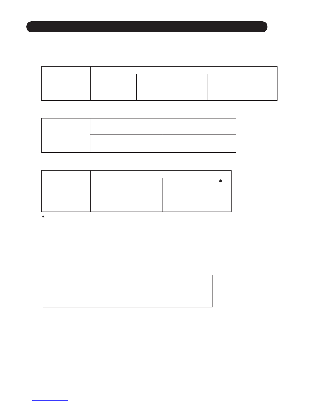
1-24. HUMAN SENSOR (OPTION )
(Table 10)
Operation mode
Cool / Dry
Heat
Operation details
(if there is no one in the room for a while)
The set temperature will be increased by
a maximum of approximately 2
°C.
The set temperature will be decreased by
a maximum of approximately 2
°C.
If no one enters the room during the set time (15, 30, 60, 90, 120, 180 minutes), the set
If no one enters the room during the set time (1 to 24 hours in 1 hour increments), the air
conditioner will automatically stop operation.
Equal sensitivity
range of temperature
Auto saving operation
Auto off operation
Application range
temperature will be automatically controlled.
(When someone comes back into the room, the human sensor will detect this, and automatically
revert to the original settings).
* High limit : 30°C
* Low limit : 16°C
Detecting position :
0.8m from floor surface
Ceiling height :
3.2m
Page 32

01-29
1-25. DRAIN PUMP OPERATION
1. When the compressor starts, the drain pump starts simultaneously.
2. The drain pump operates continuously for 3 minutes after the compressor is turned off as show in Fig15.
3. When the compressor stops by the "Anti- freezing protection", the drain pump is turned off
in 1 hour after the compressor stops.
4. When the water level in the drain pan rises up and then the float switch functions:
The compressor, indoor and outdoor fan motor operation are stopped.
Drain pump operates continuously for 3 minutes after the float switch is turned off.
(Almost condensing water may be drained)
5. When the float switch turns ON continuously for 3 minutes, "FAILURE INDICATION" operates.
(It is necessary to turn off power for release it. )
6. When the float switch turns OFF less than 3 minutes, the unit starts Cooling operation.
1
2
1.When the water level in the drain pan rises up and then the float switch functions:
Drain pump operates continuously for 3 minutes after the float switch is turned off.
(Almost condensing water may be drained)
2. When the float switch turns ON continuously for 3 minutes, "FAILURE INDICATION" operates.
Thereafter, even if the float switch turns OFF, the "FAILURE INDICATION" is not released.
(It is necessary to turn off power for release it. )
1
During Cooling / Dry mode
3 minutes
3 minutes ST
ON
OFF
ON
OFF
ON
OFF
ON
OFF
Float Switch
Compressor
Indoor Fan
Drain Pump
3 minutes
ON
OFF
ON
OFF
Float Switch
Drain Pump
During Heating / Fan mode / Stop operation
<Float Switch turns OFF less than 3 minutes>
Less than 3 minutes
.
.
The indoor unit fan motor operates after the float switch is turned off.
3
(Fig 15 : Detail of Drain Pump Operation)
3 minutes3 minutes
10 minutes 60 minutes
Start
(0 minutes)
180 minutes
3 minutes3 minutes
ON
OFF
Drain Pump
Page 33

Inv erte r co ver
01-30
1-26. DESCRIPTION OF DISPLAY UNIT For Model 45,54
•
Display lamp
Function or operation method
(1) POWER / MODE
Green
Lights on while power on. Local setting in outdoor unit or
error code is displayed with blink.
(2) ERROR
Red
Blinks during abnormal air-conditioner operation.
(3) PUMP DOWN
(L1)
Orange
Lights on during pump down operation.
(4) LOW NOISE MODE
(L2, L3)
Orange
Lights on during “Low noise” mo
de when local setting is activated.
(Lighting pattern of L2 and L3 indicates low noise level)
(5) PEAK CUT
(L4, L5, L6)
Orange
Lights on during “Peak cut” mode when local setting is activated.
(Lighting pattern of L4, L5 and L6 indicates peak cut level)
SW1 SW2 SW3 SW4 SW5
(1) (2) (3) (4) (5)
LED DISPLAY
Various settings can be adjusted by changing Push switches on the board of the outdoor unit.
( Excerpt from the "INSTALATION MANUAL" )
Switch
Function or operation method
SW1 To switch between “Local setting” and “Error code display”.
SW2
To switch between the individual “Local settings” and the
“Error code displays”.
SW3
To fix the individual “Local settings ” and the “Error code displays”.
SW4 To return to “Operation status display”.
SW5 To start the pump down operation.
MODE
SELECT
ENTER
EXIT / INITIALIZE
PUMP DOWN
PUSH SWITCH
1-00. ERROR HISTORY MODE
1-26-1 Layout of Display Unit
Page 34

01-31
•
In this mode, the "Operation Condition" and "Error Code" can be displayed by Push Switch on outdoor unit PCB
LED
Power / Mode
LED
Display Item
Compressor frequency
Upper fan speed (Outdoor unit)
Lower fan speed (Outdoor unit)
EEV pulse
Pressure sensor value (Low pressure range)
Pressure sensor value (High pressure range)
Outdoor air temperature sensor value
Discharge temperature sensor value
Heat-exchanger temperature sensor value (Middle)
Current value
Present Value
Of
Each Item
1
Compressor accumulated time
(Table :23 Procedure for
Present Value)
Procedure
Operation
Power
Mode
Error L1 L2 L6L5L4L3
1
2
3
4
During status display, press the MODE SWITCH 1 time.
(Status display : Outdoor unit is stopping and no error)
When the EXIT SWITCH is pressed, this mode ends
and returns to the status display.
Selecting display items can be done by pressing
the SELECT SWITCH. (Return to Procedure 3)
Press the ENTER SWITCH. (Data is displayed by lighting LED.
Refer to Table : 24)
When the POWER / MODE LED blinking 1
time,
press the ENTER SWITCH.
1
1
1
1
DATA
: Light ON: Light OFF : Blinking
1 :
1 Time Blinking
1-00. ERROR HISTORY MODE
1-26-2 Display mode
(Table :24 Display pattern
)
: Light ON: Light OFF
n :
n Time Blinking
5
1
Press the SELECT SWITCH and adjust to DISPLAY ITEM
(from L1 to L3) that you want to confirm. (Refer to Table : 23)
ERROR
L1 L2 L3
: Blinking
Page 35

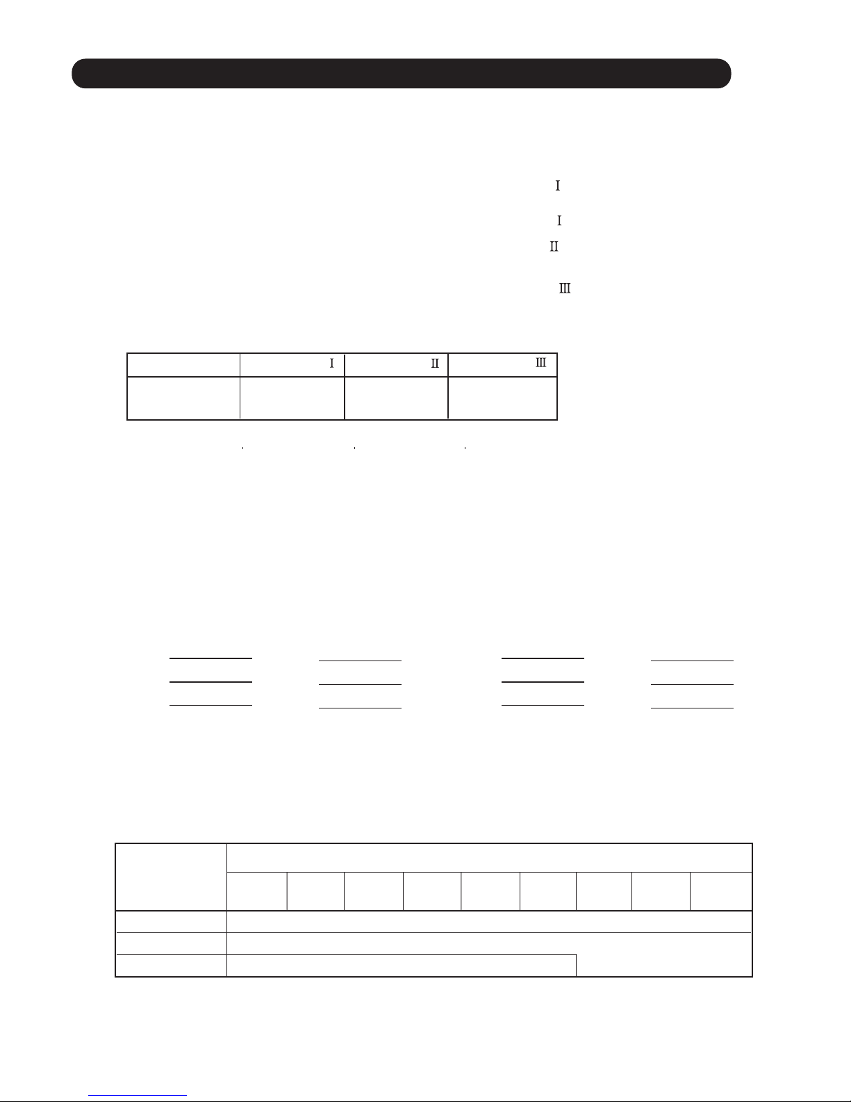
(Table 25 : Detail of LED Display Data)
: Light ON: Light OFF
1 :
1 Time Blinking
Item No,
Display Item
Power
Mode
Error L1 L2 L6L5L4L3
1
1
1
1
1
1
1
1
1
1
1
1
1
1
1
1
1
1
1
1
1
1
1
1
1
1
1
1
1
1
1
1
1
1
1
1
1
1
1
1
1
1
1
1
1
1
1
1
Compressor
Frequency
( 0 ~ 95rps )
Outdoor Unit Upper
Fan Speed
( 0 ~ 900rpm )
Outdoor Unit
Lower Fan Speed
( 0 ~ 900rpm )
EEV Pulse
( 0 ~ 480pulse )
Pressure sensor value
<Low pressure range>
( 0 ~ 2.1MPa )
Pressure sensor value
<High pressure range>
( 2.1 ~ 4.2MPa )
Check the Low Pressure
Range if it is displayed
[ ~ 2.1 ]
Check the High Pressure
Range if it is displayed
[ 1.81 ~ 2.1 ]
0
1 ~ 15
16 ~ 30
31 ~ 45
46 ~ 60
61 ~ 75
76 ~ 90
90 ~ 95
0
1 ~ 150
151 ~ 300
301 ~ 450
451 ~ 600
601 ~ 750
751 ~ 900
901 ~
0
1 ~ 150
151 ~ 300
301 ~ 450
451 ~ 600
601 ~ 750
751 ~ 900
901 ~
0
1 ~ 80
81 ~ 160
161 ~ 240
241 ~ 320
321 ~ 400
401 ~ 480
481 ~
~ 0.0
0.01 ~ 0.3
0.31 ~ 0.6
0.61 ~ 0.9
0.91 ~ 1.2
1.21 ~ 1.5
1.51 ~ 1.8
1.81 ~ 2.1
~ 2.1
2.11 ~ 2.4
2.41 ~ 2.7
2.71 ~ 3.
0
3.01 ~ 3.3
3.31 ~ 3.6
3.61 ~ 3.9
3.91 ~ 4.2
01-32
1
2
3
4
5
6
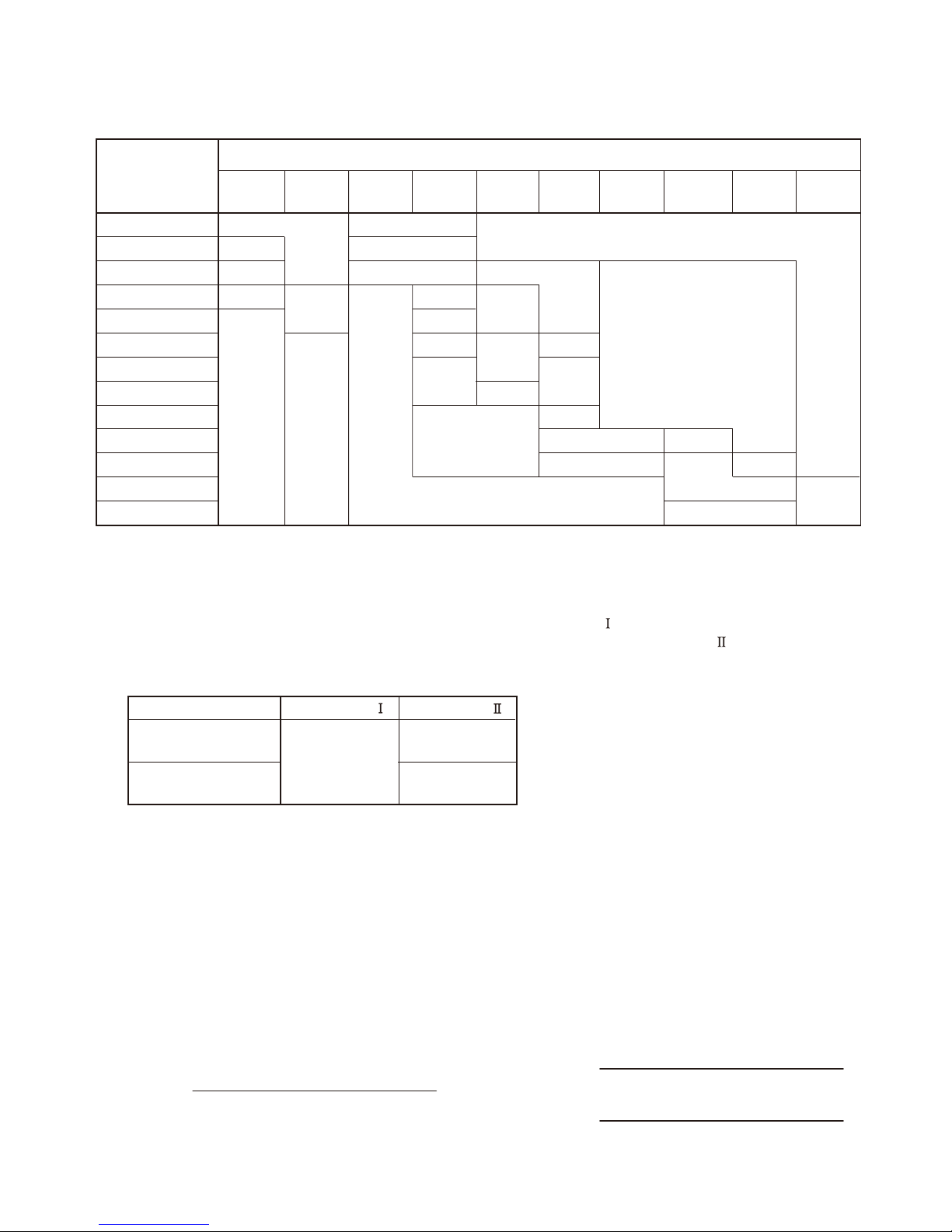
Page 36

: Light ON: Light OFF
1 :
1 Time Blinking
Item No,
Display Item
Power
Mode
Error L1 L2 L6L5L4L3
1
1
1
1
1
1
1
1
1
1
1
1
1
1
1
1
1
1
1
1
1
1
1
1
1
1
1
1
1
1
1
1
1
1
1
1
1
1
1
1
Outdoor Air
Temperature
( -30 ~ 70
°C
)
Discharge
Temperature
( -30 ~ 120
°C
)
Heat-exchanger
Temperature
<Middle>
( -30 ~ 80
°C
)
Current ( 0 ~ 10A )
Compressor
Accumulated Time
( H )
~ -15
-15 ~ -5
-5 ~ 5
5 ~ 15
15 ~ 25
25 ~ 35
35 ~ 45
45 ~
~ 55
55 ~ 65
65 ~ 75
75 ~ 85
85 ~ 95
95 ~ 105
105 ~ 115
115 ~
~ 53
53 ~ 55
55 ~ 57
57 ~ 59
59 ~ 61
61 ~ 63
63 ~ 65
65 ~
~ 0.0
0.0 ~ 1.5
1.5 ~ 3.0
3.0 ~ 4.5
4.5 ~ 6.0
6.0 ~ 7.5
7.5 ~ 9.0
9.0 ~
0
0 ~ 10000
10000 ~ 20000
20000 ~ 30000
30000 ~ 40000
40000 ~ 50000
50000 ~ 60000
60000 ~
7
8
9
01-33
<Round up by 1 hour>
10
11
Page 37

01-34
1-00. ERROR HISTORY MODE
•
In this mode, the history of abnormality that occurred in the past can be confirmed.
(Table : 26 Procedure for History Mode )
Procedure
Operation
Power
Mode
1
2
3
4
During status display, press the MODE SWITCH 2 times.
(Status display : Outdoor unit is stopping and no error)
When the EXIT SWITCH is pressed, this mode
ends and returns to the
status display
.
Selecting display items can be done by pressingthe
SELECT SWITCH. (Return to Procedure 3)
Press the ENTER SWITCH, Error code is displayed by
lighting LED. (Refer to TROUBLESHOOTING)
When the POWER / MODE LED blinking 2 ti
mes,
press the ENTER SWITCH.
: Light ON: Light OFF : Blinking
2 : 2
Times Blinking
n : n Times Blinking
1-26-3 Error history mode
Error L1 L2 L6L5L4L3
2
2
2
2
2
5
Press the SELECT SWITCH and adjust to DISPLAY ITEM
(from L1 to L3) that you want to confirm. (Refer to Table : 27)
n n
DATA
LED
Power / Mode
LED
Display Item
ERROR
L1 L2 L3
(Table :27 Display pattern
)
: Light ON: Light OFF
n :
n Time Blinking
: Blinking
Newest error code
Error code before 1 time
Error Code
2
Error code before 2 times
Page 38

2 . T ROU BLE SHOOTING
R410A
Casset te type
INVERTER
Page 39

Indoor Room Thermistor Error
Wired Remote Controller
Communication Error
Error C ontents
Trouble
shooting
02-01
2 ERROR DISPLAY
2-1 INDOOR UNIT AND WIRED REMOTE C ONTROLLER DISPLAY
Serial Communication Error
External communication Error
Combination error
Indoor unit address setting Error
Connection unit number error
(Indoor unit Wired remote controller Error)
Indoor Unit Fan Motor Error
Indoor Heat Ex. Thermistor Error
Drain pump Error
1,2
3
4
5
6
7
8
10
1- 15
16
11
12
13
14
15
17
19
18
20
21
22
23
24
IPM Error
Error
Code
11
12
41
42
51
53
5U
63
18
23
29
26
35
3A
62
64
65
71
72
73
74
77
Indoor unit Communication circuit
(wired remote controller) Error
Manual Auto SW error
9
32
Indoor unit PCB model
information Error
Indoor Unit Error
Inverter Error
Outdoor unit main PCB model
information Error
Error Contents
Trouble
shooting
25
26
27
28
29
30
31
32
33
34
Error
Code
84
86
94
95
97
98
99
A1
A3
A5
Over Current Error
Discharge Thermistor Error
Outdoor Thermistor Error
Heat Sink Thermistor Error
Current sensor Error
Pressure sensor Error
Heat Ex. Liquid Outlet
Thermistor Error
Compressor Thermistor Error
Compressor Control Error
Outdoor Unit Fan Motor 1 Error
Outdoor Unit Fan Motor 2 Error
4-way Valve Error
Discharge Temp. Error
Compressor Temp. Error
Low Pressure Error
Active filter voltage error
1. If an error occurs, an error icon appears on the “Monitor mode screen”.
Touch the [Status] on the “Monitor mode screen”.The “Status” screen is displayed.
2. Touch the [Error Information] on the “Status”screen. The “Error Information”screen is displayed.
(If there are no errors, the [Error Information] will not be displayed.)
3. 2-digit numbers correspond to the error code in the table below. Touch the [Next page]
(or [Previous page]) to switch to other connected indoor u
nits.
Example) 2WIRE remote controller
Check the Error LED display on the Indoor unit (IR Receiver *Option )
1. Check ECONOMY (Green) LED Blinking, it means the Error on the system. (Not brinking: No Error)
2. Count OPERATION (Green) LED blinks: The number of blinking means the first digit of Error code.
3. Count TIMER (Orange) LED blinks: The number of blinking means the second digit of Error code.
Example) ECONOMY: Blinking continuous / OPERATION: 4times / TIMER: 1time Indoor Room Thermistor Error
Mode Set Temp.
Fri 10:00AM
Menu
kcaBrotinoM
Page 1/ 4
Page 1/ 5
Air Flow Direction
Economy
VT
Individual
Error Code
Address
[ 1 ]
[ 02 01 ]
[ 14 . 15, 41 . 44 ]
[ ]
[ Off ]
Next
Page
Next
Page
Error
Information
Status
Status
Error Information
Fan
!
1.
2.
3.
44rorrE rosneS namuH
Check the Error code on the wired remote controller (Remote controller *Option)
Page 40
Check that the “ERROR” LED blinks, then press the [Enter] button once.
For details, refer to the following table.
2-1-2 OUTDOOR UNIT DISPLAY For Model 45,54
Error Contents
POWER
MODE
ERROR
Serial Communication Error
2
2
2
2
2
2
2
2
2
1
(L1) (L2) (L6)(L5)(L4)(L3)
IPM Error
Indoor Unit Error
Inverter Error
Over Current Error
Discharge Thermistor Error
Outdoor Thermistor Error
Heat Sink Thermistor Error
Current sensor Error
Pressure sensor Error
Compressor Thermistor Error
Compressor Control Error
Outdoor Unit Fan Motor 1 Error
Outdoor Unit Fan Motor 2 Error
4-way Valve Error
Discharge Temp. Error
Compressor Temp. Error
Low Pressure Error
2
2
2
2
2
2
2
2
2
2
1
5
6
3
6
5
7
1
20
7
2
7
3
7
4
7
7
8
4
8
6
9
4
9
5
9
7
9
8
9
9
01 1
01
3
01 5
51
Heat Ex. Liquid Outlet
Thermistor Error
LED DISPLAY
PUMP
DOWN
LOW
NOISE
PEAK
CUT
Trouble
shooting
1,2
17
19
21
22
23
24
25
26
27
28
29
30
31
32
33
34
1-15
1 ~ 15 : 1~ 15 Times Blinking
: Light ON:FFO thgiL :
2 : 2Times Blinking
You can determine the operating status by the lighting up and blinking of the LED lamp.
LED display part
Display when an error occurs.
POWER/
MODE
ERROR
PUMP
DOWN
LOW
NOISE
PEAK
CUT
(L1) (L2) (L3) (L4) (L5) (L6)
Blink
(Hi speed)
Sign “ ”: Lights off, “ ”: Lights on
Check that the “ERROR” LED blinks, then press the “ENTER” button once.(1)
For details, refer to the following table.(2)
02-02
Page 41
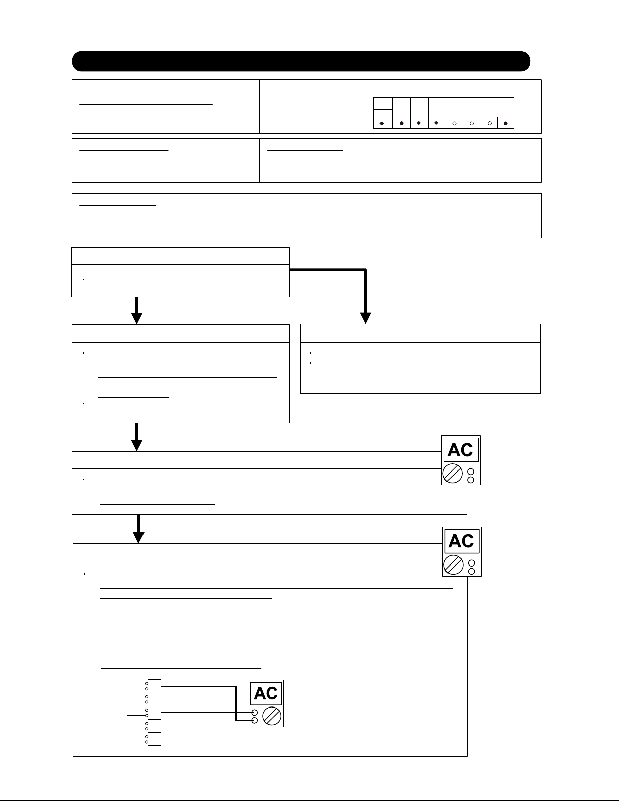
Trouble shooting 1
OUTDOOR UNIT Error Method:
Detective Actuators: Detective details:
Forecast of Cause:
OK
Indicate or Display:
YESYES
NO
Serial Communication Error
(Serial Reverse Transfer Error)
Outdoor unit Main PCB
Outdoor unit Fan motor
1. Connection failure 2. External cause 3. Main PCB failure 4. Active filter module failure
5. Transistor PCB (IPM) failure 6. Filter PCB failure 7. Outdoor unit Fan motor failure
Check Point 1-1 : Reset the power and operate
Does error indication reappear?
Check Point 1-2 : Check external cause such as noise
Check if the ground connection is proper.
Check if there is any equipment that causes harmonic wave
near the power cable (Neon light bulb or any electronic
equipment which causes harmonic wave).
Check Point 2 : Check connection
Check any loose or removed connection line of
between indoor unit and outdoor unit.
>> If there is an abnormal condition, correct it by
referring to Installation Manual or Data &
Technical Manual.
Check connection condition in control unit.
(If there is loose connector, open cable or mis-wiring)
Check Point 3 : Check the voltage of power supply
Check the voltage of power supply
>> Check if AC198V(AC220V-10%) - 264V(AC240V+10%) appears
at outdoor unit terminal L - N.
When the indoor unit cannot receive the serial signal from Outdoor unit
more than 2minutes after power ON, or the indoor unit cannot receive
the serial signal more than 15seconds during normal operation.
Error code : 11
Outdoor unit : Model 45.54
2-2 TROUBLE SHOOTING WITH ERROR CODE
OK
Check Point 4 : Check serial signal (Reverse transfer signal)
Check serial signal (Reverse transfer signal)
>> Check if indicated value swings between AC90V and AC270V at outdoor unit terminal 1 - 3.
>> If it is abnormal, Check the parts as follows.
- Outdoor unit fan motor (PARTS INFORMATION 5)
- Active filter module (PARTS INFORMATION 6)
- Transistor PCB (IPM) (PARTS INFORMATION 7)
- Filter PCB (Check the wire of CN110)
>> If Outdoor fan motor is abnormal, replace Outdoor unit fan motor and Main PCB.
>> If
Active filter module or IPM is abnormal, replace it.
>> If the parts are normal, replace Main PCB.
1
2
3
L
N
RED
WHITE
BLACK
BLACK
WHITE
+
-
POWER
MODE
ERROR
2
5
)6L()2L()1L( (L5)(L4)(L3)
15
PUMP
DOWN
LOW
NOISE
PEAK
CUT
02-03
Page 42

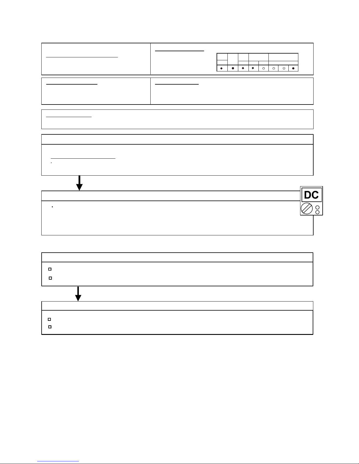
Trouble shooting 2
INDOOR UNIT Error Method:
Detective Actuators: Detective details:
Forecast of Cause:
OK
YESYES
NO
OK
Serial Communication Error
(Serial Forward Transfer Error)
Indoor unit Controller PCB
1. Connection failure 2. External cause 3. Controller PCB failure
Check Point 1-1 : Reset the power and operate
Does error indication reappear?
Check Point 1-2 : Check external cause such as noise
Check if the ground connection is proper.
Check if there is any equipment that causes harmonic wave
near the power cable (Neon light bulb or any electronic
equipment which causes harmonic wave).
Check Point 2 : Check connection
Check any loose or removed connection line of
between indoor unit and outdoor unit.
>> If there is an abnormal condition, correct it by
referring to Installation Manual or Data &
Technical Manual.
Check connection condition in control unit.
(If there is loose connector, open cable or mis-wiring)
Check Point 3 : Check the voltage of power supply
Check the voltage of power supply
>> Check if AC198V(AC220V-10%) - 268V(AC240V+10%) appears
at outdoor unit terminal L - N.
Check Point 4 : Check serial signal (Forward transfer signal)
Check serial signal (Forward transfer signal)
>> Check if indicated value swings berween AC30v and AC130V at outdoor unit terminal 2 - 3.
>> If it is abnormal, replace Controller PCB.
When the outdoor unit cannot properly receive the serial signal from
indoor unit for 10 seconds or more.
02-04
1
2
3
L
N
RED
WHITE
BLACK
BLACK
WHITE
+
-
Indicate or Display:
Error code : 11
POWER
MODE
ERROR
2
2
1
(L1) (L2) (L6)(L5)(L4)(L3)
1
1
1
PUMP
DOWN
LOW
NOISE
PEAK
CUT
Outdoor unit : Model 45.54
Page 43
Trouble shooting 3
INDOOR UNIT Error Method:
Detective A ctuators: Detective details:
Forecast of Cause:
Check Point 1-2 : Check Wired Remote Controller and Controller PCB
Check Point 1 : Check the connection of terminal
OK
Wired Remote Controller
Communication Error
Indoor unit Controller PCB
Wired Remote Controller
1. Connection failure 2. Wired Remote Controller failure 3. Controller PCB failure
Check & correct the followings.
Check the connection of terminal berween Wired Remote Controller and indoor unit,
and check if there is a disconnection of the cable.
After turning off the power,
When the indoor unit cannot properly receive the signal from
Wired Remote Controller for 1 minute or more.
>> If it is DC13V , Remote Control is failure. (Controller PCB is n ormal) >> Replace Remote Contro l
>> If it is DC 0V, Controller PCB is failure. (Check Remote Control once again) >> Replace Controller PC B
Ceck Voltage at CN14 of Controller PCB. (Terminal 1-3, Terminal 1-2)
(Power supply for the Remote Control)
In di c a te o r D i s p l ay :
Error code : 12
POWER
MODE
ERROR
2
5
(L1) (L2) (L6)(L5)(L4)(L3)
15
PUMP
DOWN
LOW
NOISE
PEAK
CUT
02-05
Outdoor unit : Model 45.54
Check Point 2-1 : Check Indoor unit controller PCB
The number of connecting indoor unit and Remote controller in one RCgroup were less than 32 units.
Check Point 2 : Wire installation Wrong RCgroup setting
Wrong wire connection in RCgroup (Please refer to the installation manual)
Change controller PCB and ch eck the Error after setting remote controller address
Check if controller PCB damage
Page 44
Trouble s hooting 4
INDOOR UNIT E rror Method:
External communication error
Detective Actuators:
Detective details:
Forecast of Cause :
OKOK
External communication error
Check any loose or removed connection of between the controller PCB to the external I/OPCB
>>If there is an abnormal condition, correct it by refer to installation manual or
the tec hnical manual.
Check the condition condtion on the external I/O PCB and the controller PCB
(If there is loose connector, open cable or mis-wiring)
the same a signal has not been received for 15sec
After receiving a signal from the external I/O PCB,
1. Connection failure 2.External I/O PCB failure 3.Controller PCB failure
Check Point 1 : Check the connection
Check Point 2: Replace external I/O PCB
If Chec k Point 1 do not improve the symptom, change External I/O PC B.
OKOK
Check Point 3: Replace Controller PCB
If Chec k Point 2 do not improve the symptom, change Controller PCB.
Indicate or Display:
Error code : 18
POWER
MODE
ERROR
2
5
)6L()2L()1L( (L5)(L4)(L3)
15
PUMP
DOWN
LOW
NOISE
PEAK
CUT
02-06
Outdoor unit : Model 45.54
Page 45

Trouble s hooting 5
INDOOR UNIT Error Method:
Detective Actuators: Detec tive details:
1. When the outdoor unit type is multi.
Forecast of Cause:
OK
Combination error
Indoor unit
1. The selection of indoor units is incorrect
Check Point 1 : Check the type of indoor unit
Check the type of the connected indoor unit.
>> If abnormal condition is found, correct it.
Check Point 2 : Replace Main PCB
If Chec k Point 1 do not improve the symptom, replace Main PCB of Outdoor unit.
Indicate or Display:
Error code : 23
POWER
MODE
ERROR
2
5
)6L()2L()1L( (L5)(L4)(L3)
15
PUMP
DOWN
LOW
NOISE
PEAK
CUT
02-07
Outdoor unit : Model 45.54
Page 46

Detective Actuators:
Wired remote controller ( 2-Wire )
Indoor unit Controller PCB circuit
Detective details:
When the address number set by auto setting and manual setting are mixed in
one RC group.
When the duplicated address number exists in one RC group.
Check Point 3 : Check Indoor unit controller PCB
Forecast of Cause :
1. Wrong wiring of RCgroup 2. Wrong remote address setting 3. Indoor unit controller PCB failure
4. Remote controller failure
Check Point 1 : Wire installation
Wrong wire connection in RCgroup (Please refer to the installation manual)
Change controller PCB and check the Error after setting remote controller address
Check if controller PCB damage
Check Point 2 : Wrong RCgroup setting
The given address number by auto setting (00) and the manual set number (Except 00) were not existing in one RCG.
The remote controller address setting by U.I. were not existing same address.
The duplicated address number is not existing in one RCgroup
Trouble s hooting 6
INDOOR UNIT Error Method:
Indoor unit address setting error
Indicate or Display:
Error code : 26
POWER
MODE
ERROR
2
5
)6L()2L()1L( (L5)(L4)(L3)
15
PUMP
DOWN
LOW
NOISE
PEAK
CUT
02-08
Outdoor unit : Model 45.54
Page 47

02-09
Trouble shooting 7
INDOOR UNIT E rror Method:
Connection unit number error (Indoor
unit in Wired remote controller system)
Detective Actuators:
Wired remote controller ( 2-Wire )
Indoor unit Controller PCB circuit
Detective details:
When the number of connecting indoor units are out of specified rule.
Forecast of Caus e :
1. Wrong wiring / Number of I.U, RC in RCgroup 2. Indoor unit controller PCB defective
Check Point 1 : Wire installation
Wrong number of connecting indoor unit
Check Point 2 : Check Indoor unit controller PCB
Check if controller PCB damage
Check if controller PCB and check the Error after setting remote controller address
Indicate or Display:
Error code : 29
POWER
MODE
ERROR
2
5
)6L()2L()1L( (L5)(L4)(L3)
15
PUMP
DOWN
LOW
NOISE
PEAK
CUT
Outdoor unit : Model 45.54
Page 48

Detective Actuators:
Detective details:
Forecast of Cause:
Check Point 3 : Replace Controller PCB
Check Point 2 :
Check Indoor unit electric components
YE SYE S
NO
Trouble s hooting 8
INDOOR UNIT Error Method:
Indoor unit PCB model
information error
Indoor unit Controller PCB
1. External cause 2. Defective connection of electric components 3. Controller PCB failure
Check Point 1-1 : Reset Power Supply and operate
Does Error indication show again?
Check Point 1-2 :
Check external cause such as noise
Check if the ground connection is proper.
Check if there is any equipment that causes harmonic wave
near the power cable (Neon light bulb or any electronic
equipment which causes harmonic wave).
Note : EEPROM
EEPROM(Electronically Erasable and
Programmable Read Only Memory) is a nonvolatile memory which keeps memorized
information even if power is turned off. It can
change the contents electronically.
To change the contents, it uses higher
voltage than normal, and it can not change a
partial contents. (Rewriting shall be done
upon erasing the all contents.)
There is a limit in a number of rewriting.
Change Controller PCB.
Check all connectors.
(loose connector or incorrect wiring)
Check any shortage or corrosion on PCB.
When power is on and there is some below case.
1. When model information of EEPROM is incorrect.
2. When the access to EEPROM failed.
Indicate or Display:
Error code : 32
POWER
MODE
ERROR
2
5
)6L()2L()1L( (L5)(L4)(L3)
15
PUMP
DOWN
LOW
NOISE
PEAK
CUT
02-10
Outdoor unit : Model 45.54
Page 49

Trouble s hooting 9
INDOOR UNIT Error Method:
Detective Actuators: Detec tive details:
Forecast of Cause :
OKOK
Manual Auto Switch Error
Indoor Unit Controller PCB
Indicator PCB
Manual Auto Switch
When the Manual Auto Switch becomes ON for consecutive 30 or
more seconds.
1. Manual Auto Switch failure 2. Controller PCB and Indicator PCB failure
Check Point 1 : Check the Manual Auto Switch
Check if Manual Auto Switch is kept pressed.
Check ON/OFF switching operation by using a meter.
>> If Manual Auto S witch is disabled (on/off switc hing), replace it.
Check Point 2 : Replace Controller PCB and Indicator PCB
If Chec k Point 1 do not improve the symptom, replace Controller PC B and Indicator PCB
and execute the check operation again.
02-11
Indicate or Display:
ERROR CODE : 35
POWER
MODE
ERROR
2
5
)6L()2L()1L( (L5)(L4)(L3)
15
PUMP
DOWN
LOW
NOISE
PEAK
CUT
Outdoor unit : Model 45.54
Page 50

Trouble s hooting 10
INDOOR UNIT Error Method:
Indoor unit Communication circuit
(wired remote controller) error
Detective Actuators:
Indoor unit Controller PCB circuit
Detective details:
OK
Detect the communication error of microcomputer and communication PCB.
Check Point 2 : Replace the communication PCB
OK
Forecast of Cause :
2. Indoor unit controller PCB defective
1.Communication PCB defective
Check Point 1 : Check the connection of terminal
Indoor unit - Check the connection the communication PCB and the controller PCB
After turning off the power supply, check & correct the followings
If the Check point 1 is ok, replace the communication PCB
Indicate or Display:
Error code : 3A
POWER
MODE
ERROR
2
5
)6L()2L()1L( (L5)(L4)(L3)
15
PUMP
DOWN
LOW
NOISE
PEAK
CUT
02-12
Check Point 3 : Replace the controller PCB
If condition doesn’t change, replace the controller PCB
Outdoor unit : Model 45.54
Page 51

Detective Actuators :
Indoor Unit Controller PCB Circuit
Indoor Temperature Thermistor
Detective details:
Indoor unit thermistor is open or short is detected always.
Forecast of Caus e :
1. Connector failure connection 2. Thermistor failure 3. Controller PCB failure
Check Point 2 : Remove connector and check Thermistor resistance value
Thermistor Characteristics(Rough value)
If Thermis tor is either open or shorted, replace it and reset the power.
Check Point 1 : Check connection of Connector
Check if connector is loose or removed
Check erroneous connection
Check if thermistor cable is open
>>Reset Power when reinstalling due to removed connector or incorrect wiring.
6.58.010.012.515.820.225.933.6
3.594.355.3Resistance value (k )
OK
OK
Check Point 3 : Check Voltage of Controller PCB (DC 5.0V)
Make sure circuit diagram of each indoor unit and check terminal voltage at Thermistor (DC5.0V)
If the voltage does not appear, replace Controller PC B and execute the check operation again.
DC
Trouble s hooting 11
INDOOR UNIT E rror Method:
Indoor Room Thermistor Error
Temperature (°C )
Temperature (°C )
0
40 45 50
5 10 15 20 25 30 35
Resistance value (k )
BLACK
BLACK
1
2
CN8
H/E Thermistor
Room Temp. Thermistor
BLACK
BLACK
1
2
CN32
Indicate or Display:
Error code : 41
POWER
MODE
ERROR
2
5
)6L()2L()1L( (L5)(L4)(L3)
15
PUMP
DOWN
LOW
NOISE
PEAK
CUT
02-13
Outdoor unit : Model 45.54
Page 52

Detective Actuators :
Indoor Unit Controller PCB
Heat Exchanger (MID) Thermistor
Detective details:
Indoor unit thermistor is open or short is detected always.
Forecast of Caus e :
1. Connector failure connection 2. Thermistor failure 3. Controller PCB failure
Check Point 1 : Check connection of Connector
Check if connector is loose or removed
Check erroneous connection
Check if thermistor cable is open
>>Res et Power when reinstalling due to removed connector or incorrect wiring.
Trouble s hooting 12
INDOOR UNIT E rror Method:
rouble shooting
INDOOR UNIT E rror Method:
Indoor Heat E x. Thermistor Error
31.739.649.762.980.3103134176
17.120.825.6Resistance value (k )
Temperature (°C )
Temperature (°C )
0
40 45 50
5 10 15 20 25 30 35
Resistance value (k )
Check Point 2 : Remove connector and check Thermistor resistance value
Thermistor Characteristics(Rough value)
If Thermis tor is either open or shorted, replace it and reset the power.
OK
OK
Check Point 3 : Check voltage of Controller PCB (DC5.0V)
Make sure circuit diagram of each indoor unit and check terminal voltage at Thermistor (DC5.0V)
If the voltage does not appear, replace Controller PC B and execute the check operation again.
DC
BLACK
BLACK
1
2
CN8
H/E Thermistor
Room Temp. Thermistor
BLACK
BLACKB
1
2
CN32
Indicate or Display:
Error code : 42
POWER
MODE
ERROR
2
5
)6L()2L()1L( (L5)(L4)(L3)
15
PUMP
DOWN
LOW
NOISE
PEAK
CUT
02-14
Outdoor unit : Model 45.54
Page 53

02-15
Trouble s hooting 13
INDOOR UNIT Error Method:
Detective Actuators:
Detective details:
Forecast of Cause:
Human sensor error
Indoor unit Main PCB
2. Sensor failure eruliaf BCP niaM tinu roodnI .3eruliaf noitcennoC .1
2 When the signal from the sensor is "L"(=0V) for more than 10 min.
1
Detect the open condition of the sensor.
Check Point 1 : Check the connector connection and cable open
Check Point 2 : Conduction check
Check if connector is loose or removed
Check erroneous connection
Check if sensor cable is open
>>Reset Power when reinstalling due to removed connector or incorrect wiring.
OK (S ensor connections error) OK(S ensor signal error)
Disconnect the sensor and check the 2-3pin
on sensor connector.
>>With conduction : Main PCB failure
>>Without conduction : Sensor failure
Check Point 2 : Voltage check
Disconnect the sensor and check the Voltage
of 1pin of the CN10 on the Main PCB
>>5V: Sensor failure
>>Other than 5V: Main PCB failure
Indicate or Display:
Error code : 44
POWER
MODE
ERROR
2
5
)6L()2L()1L( (L5)(L4)(L3)
15
PUMP
DOWN
LOW
NOISE
PEAK
CUT
Outdoor unit : Model 45.54
Page 54

02-16
Trouble s hooting 14
INDOOR UNIT E rror Method:
Indoor Unit Fan Motor1 Error
Detective Actuators:
Detective details:
Forecast of Cause:
Check Point 1 : Check rotation of Fan
Check Point 2 : Check ambient temp. around motor
OK
OK
OK
Indoor unit Power Supply PCB
Indoor unit fan motor
1. Fan rotation failure 2. Fan motor winding open 3. Motor protection by surrounding temperature rise
4. Power Supply PCB failure 5. Indoor unit fan motor failure
Rotate the fan by hand when operation is off.
(Check if fan is caught, dropped off or locked motor)
>>If Fan or B earing is abnormal, replace It.
Check excessively high temperature around the motor.
(if there is any surrounding equipment that causes heat)
>>Upon the temperature coming down, restart operation.
When the fan motor speed is less than 1/3 of the target fan speed
for 56 seconds.
When detect the 0 rpm for 56 seconds after fan motor started.
Check Point 4 : Replace Power Supply PCB
If Chec k Point 1- 3 do not improve the symptom, replace Power Supply PCB.
Check Point 3 : Check Indoor unit fan motor
Check Indoor unit fan motor. (PARTS INFORMATION 4)
>>if Indoor unit fan motor is abnormal, replace Indoor unit fan motor.
Indicate or Display:
Error code : 51
POWER
MODE
ERROR
2
5
)6L()2L()1L( (L5)(L4)(L3)
15
PUMP
DOWN
LOW
NOISE
PEAK
CUT
Outdoor unit : Model 45.54
Page 55

Trouble shooting 15
INDOOR UNIT Error Method:
Drain pump Error
Detective Actuators:
Indoor Unit Controller PCB Circuit
Float Switch
Detective details:
When Float switch is ON for more than 3 minutes.
Check Point 1 : Check Float Switch
Check operation of float switch. (any blocking by dust, etc.)
Remove Float switch and check ON/OFF switching operation
by using a meter.
>>If Float switc h is abnormal, replace it.
ON OFF
OK
Fo recas t of C ause :
1. Float switch failure 2. Shorted connector/wire 3. Controller PCB failure
4. Drain pump failure 5. Hose clogging
Check Point 2 : Check Connector and Wire
Check loose contact of CN9 and shorted wire (pinched wire).
>>Replace Float switch if the wire is abnormal
OK
Check Point 3 : Check Drain Hose
Check Drain Hose .
>>If there is Hose clogging. Please clear the clog.
02-17
Indicate or Display:
Error code : 53
POWER
MODE
ERROR
2
5
)6L()2L()1L( (L5)(L4)(L3)
15
PUMP
DOWN
LOW
NOISE
PEAK
CUT
Outdoor unit : Model 45.54
Check Point 4 : Check Controller PCB and Drain Pump
If drain pump is not run on the working condition, check the voltage of the C N71 on the controller PCB.
12V : Replace the Drain Pump
Measurement result
Other than 12V : Replace the controller PCB
OK
Check Drain Pump.
WHITE
RED
CN71-1
CN71-2
CN71-3
CN71-4
CN71
DC DRAIN PU MP MOTOR
M
B
DC12V
Page 56

Detective Actuators: Detective details:
Forecast of Cause:
Check Point 2 : Replace Main PCB
YE SYE S
NO
Trouble s hooting 16
OUTDOOR UNIT E rror Method:
Outdoor unit main PCB model
information error
Outdoor unit Main PCB
1. External cause (Noise, temporary open, voltage drop) 2. Main PCB failure
Check Point 1-1 : Reset Power Supply and operate
Does Error indication show again?
Check Point 1-2 : Check external cause
Check if temporary voltage drop was not generated.
Check if momentary open was not generated.
Check if ground is connection correctly or there are no related
cables near the power line.
Change Main PC B.
Access to EEPROM failed due to some cause after outdoor unit started.
02-18
Indicate or Display:
Error code : 62
POWER
MODE
ERROR
2
6
)6L()2L()1L( (L5)(L4)(L3)
2
PUMP
DOWN
LOW
NOISE
PEAK
CUT
Outdoor unit : Model 45.54
Page 57

Inverter Error
YE S
NO
OK
Check Point 1-2 : External cause
Transistor PCB Error information received from Transistor PCB
1. External cause. 2. Power supply to Filter PCB to Inverter PCB
wiring disconnection, open 3. Filter PCB failure 4. Transistor PCB failure
Check if temporary voltage drop was not generated.
Check if temporary open was not generated.
Check if ground is connected correctly or there are no related cables near the
power line.
Check Point 2 : Check the wiring (Power supply to Filter PCB to Inverter PCB)
Connector and wiring connection state check
Cable open check
Replace Filte
r PCB and Inverter PCB.
Check Point 1-1 :
Turn the power on again.
Error displayed again?
Check Point 3 : Replace Filter PCB (INV) and Inverter PCB
02-19
Trouble s hooting 17
Detective Ac tuators:
Detective details:
OUTDOOR UNIT Error Method:
Forecast of Cause :
POWER
MODE
ERROR
)6L()2L()1L( (L5)(L4)(L3)
PUMP
DOWN
LOW
NOISE
PEAK
CUT
2 6 3
Indicate or Display:
Error code : 63
Outdoor unit : Model 45.54
Page 58

Trouble s hooting 18
OUTDOOR UNIT E rror Method:
Active filter voltage error
02-20
Detective Actuators:
Detective details:
Forecast of Cause :
OKOK
OKOK
Outdoor unit Main PCB
Active filter module
Transistor PCB
1. External cause 2. Connector connection failure 3. Main PCB failure 4. Active filter module failure
5. Transistor PCB failure
Check Point 2 : Check connection of Connector
Check if connector is removed.
Check erroneous connection.
Check if cable is open.
>>Upon correcting the removed connector or mis-wiring, reset the power.
Check Point 4 : Check Transistor PCB
Check Point 1 : Check external cause at Indoor and Outdoor (Voltage drop or Noise)
Instant drop : Check if there is a large load electric apparatus in the same circuit.
Momentary power failure : Check if there is a defective contact or leak current
in the power supply circuit.
Noise : Check if there is any equipment causing harmonic wave near electric line.
(Neon bulb or electric equipment that may cause harmonic wave)
Check the complete insulation of grounding.
OK
Check Point 5 : Replace Main PCB
If Chec k Point 1 - 4 do not improve the symptom, change Main PC B.
OKOK
Check Point 3 : Check Active filter module
Check Active filter module.
>>If Active filter module is abnormal, replace it.
Check Transistor PCB
>>If Transis tor PC B is abnormal, replace it.
When inverter input DC voltage is higher than 430V or
lower than 110V.
When a momentary power cut off occurred on low voltage
Outdoor unit : No indication
Indicate or Display:
Error code : 64
Page 59
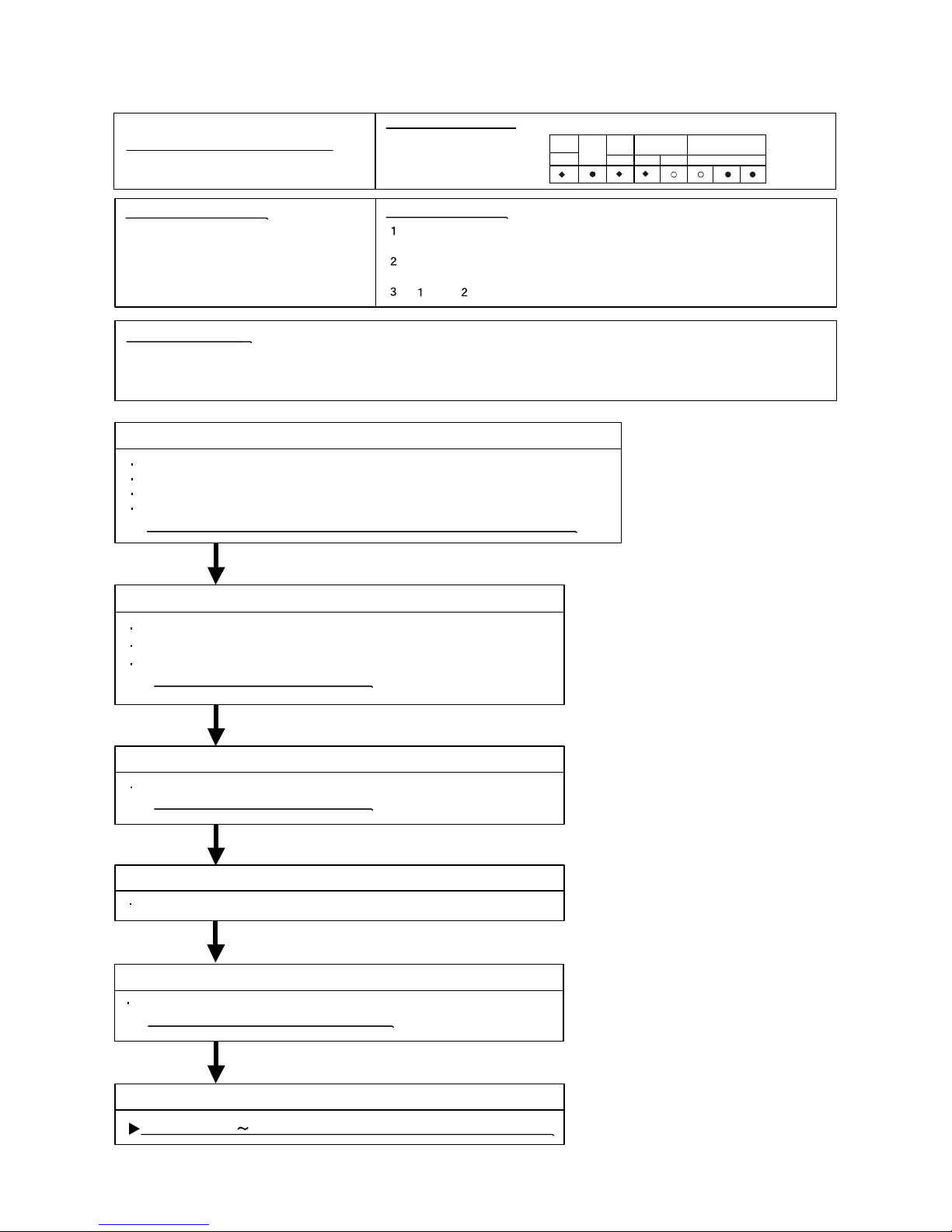
Detective Actuators:
Detective details :
Forecast of Cause :
Check Point 3 : Check Outdoor Fan
OK
OK
Check Point 6 : Replace Main PCB
OKOK
OKOK
Check Point 1 :
Check connections of Outdoor Unit Electrical Components
Outdoor unit Main PCB
C
Transistor PCB
ompressor
1. Defective connection of electric components 2. Outdoor Fan Operation failure
3
6. Transistor PCB failure
. Outdoor Heat Exchanger clogged 4. Compressor failure 5. Main PCB failure
Check if connector is removed.
Check if
the terminal connection
is loose.
Check erroneous connection.
Check if cable is open.
>>Upon correcting the removed connector or mis-wiring, reset the power.
Check Point 2 : Check Outdoor Fan, Heat Exchanger
Is there anything obstructing the air distribution circuit?
Is there any clogging of Outdoor Heat Exchanger?
Is the Fan rotating by hand when operation is off ?
>> If the Fan Motor is locked, replace it.
Check Outdoor Fan Motor. (Refer to Trouble shooting 29,30)
>> If the Fan Motor is failure, replace it.
Check Point 4 : Check Compressor
(P ARTS INF ORMATIO N 2)
Check Compressor.
If Chec k Point 1 5 do not improve the symptom, change Main PCB .
When more than normal operating current to IPM in Main PCB flows,
the compressor stops.
After the compressor restarts, if the same operation is repeated within 40sec,
the compressor stops again.
If and repeats 5 times, the compressor stops permanently.
02-21
Trouble s hooting 19
OUTDOOR UNIT E rror Method:
IPM Error
Indicate or Display:
Error code : 65
POWER
MODE
ERROR
2
6
)6L()2L()1L( (L5)(L4)(L3)
5
PUMP
DOWN
LOW
NOISE
PEAK
CUT
OKOK
Check Point 5 : Check Transistor PCB
Check Transistor PCB
>>If Transis tor PCB is abnormal, replace it.
Outdoor unit : Model 45.54
Page 60

Discharge Thermistor Error
OK
OK
DC
Discharge temperature thermistor
Discharge temperature thermistor short detected
Discharge thermistor open detected
1. Connector connection failure, open
2. Thermistor failure
3. Main PCB failure
Check Point 1 : Check the connector connection and cable open
Connector connection state check
Cable open check
Check Point 2 : Check the thermistor
Thermistor characteristics check (Disconnect the thermistor from the PCB and check.)
* For the thermistor characteristics, refer to the "Service Parts Information 8".
Check Point 3 : Check voltage of Main PCB (DC5.0V)
Main PCB 30/36(CN63:1-2) 45/54(CN62:1-2) voltage value = 5V
Remove the thermistor from Main PCB, check the voltage.
If the voltage does not appear, replace Main PCB
,
and execute the check operation again.
02-22
Trouble s hooting 20
Detective Actuators:
Detective details:
OUTDOOR UNIT Error Method:
Forecast of Cause :
Indicate or Display:
Error code : 71
POWER
MODE
ERROR
2
7
)6L()2L()1L( (L5)(L4)(L3)
1
PUMP
DOWN
LOW
NOISE
PEAK
CUT
Outdoor unit : Model 45.54
CN62
THERMISTOR
(COMP SHELL)
THE RMIS TOR
(DIS.PIPE.)
BLACK
BLACK
BL AC K
BL AC K
[45/ 54]
1 2
3 4
1 2
3 4
Discharge temperature thermistor (
CN62:1-2)
BROWN
BROWN
[30/ 36]
CN63
THERMISTOR
(DIS.PIPE.)
321
321
Discharge temperature thermistor (
CN63:1-3)
Page 61

Compressor Thermistor E rror
DC
Compressor temperature thermistor
Compressor temperature thermistor short detected
Compressor thermistor open detected
1. Connector connection failure, open
2. Thermistor failure
3. Main PCB failure
OK
OK
Check Point 1 : Check the connector connection and cable open
Connector connection state check
Cable open check
Check Point 2 : Check the thermistor
Thermistor characteristics check (Disconnect the thermistor from the PCB and check.)
* For the thermistor characteristics, refer to the "Service Parts Information 8".
Check Point 3 : Check voltage of Main PCB (DC5.0V)
Main PCB 30/36(CN64:1-3) 45/54(CN62:3-4) voltage value = 5V
Remove the thermistor from Main PCB, check the vol
tage.
If the voltage does not appear, replace Main PCB
, and execute
the check operation again.
02-23
Trouble s hooting 21
Detective Actuators:
Detective details:
OUTDOOR UNIT Error Method:
Forecast of Cause :
Indicate or Display:
Error code : 72
POWER
MODE
ERROR
2
7
)6L()2L()1L( (L5)(L4)(L3)
2
PUMP
DOWN
LOW
NOISE
PEAK
CUT
Outdoor unit : Model 45.54
[30/ /54[]63 54]
BROWN
BROWN
CN64
THERMISTOR
(COMP.TEMP.)
123
123
Compressor temperature thermistor(CN64:1-3) Compressor temperature thermistor(CN62:3-4)
CN62
THE RMIS TOR
(COMP SHE LL )
THERMISTOR
(DIS.PIPE.)
BLAC K
BLAC K
BLACK
BLACK
1 2
3 4
1 2
3 4
Page 62
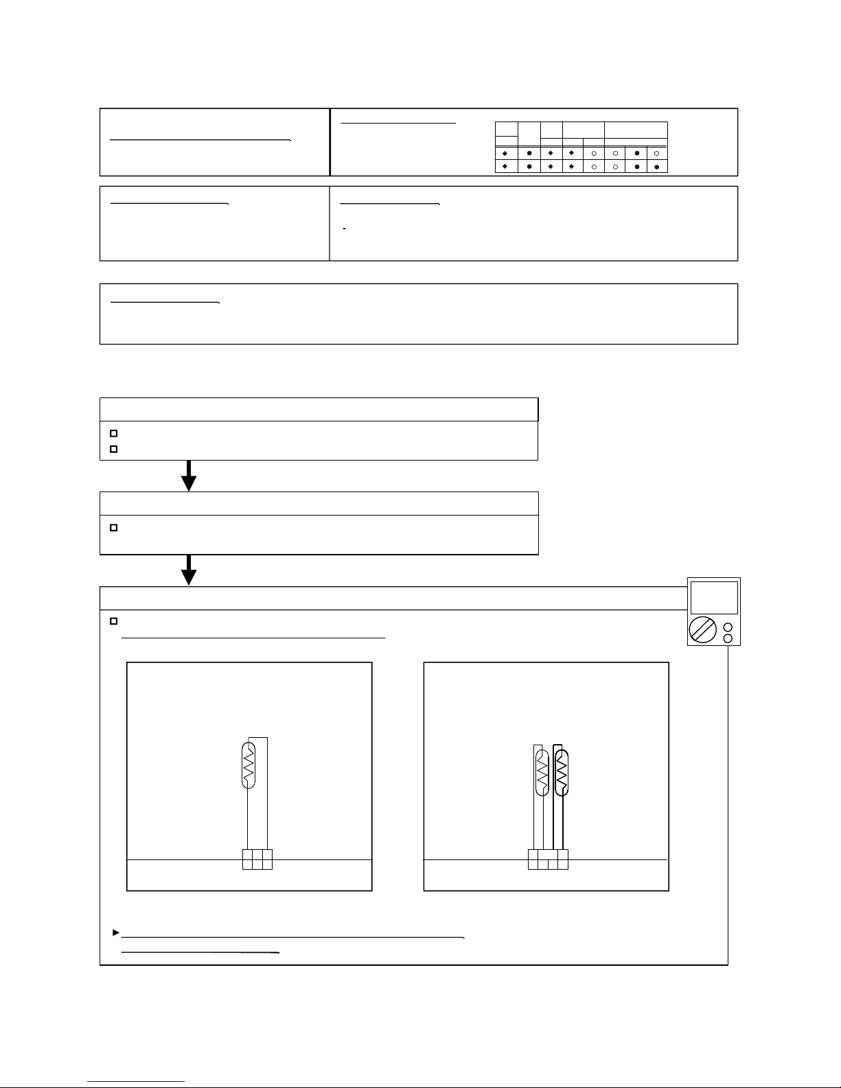
DC
Heat exchanger liquid temperature
thermistor
Heat exchanger outlet temperature thermistor short or open detected
1. Connector connection defective, open
2. Thermistor failure
3. Main PCB failure
OK
OK
Check Point 1 : Check the connector connection and cable open
Connector connection state check
Cable open check
Check Point 2 : Check the thermistor
Thermistor characteristics check (Disconnect the thermistor from the PCB and check.)
* For the thermistor characteristics, refer to the "Service Parts Information 8".
Check Point 3 : Check voltage of Main PCB (DC5.0V)
Main PCB 30/36(CN65:1-3) 45/54(CN63:1-2) voltage value = 5V
Remove the thermistor from Main PCB
, check the voltage.
If the voltage does not appear, replace Main PCB
, and execute
the check operation again.
If the voltage does not appear,
02-24
Heat Ex. Outlet Temp.
Thermistor Error
Trouble s hooting 22
Detective Actuators:
Detective details:
OUTDOOR UNIT Error Method:
Forecast of Cause :
POWER
MODE
ERROR
2
2
7
)6L()2L()1L( (L5)(L4)(L3)
3
7 3
PUMP
DOWN
LOW
NOISE
PEAK
CUT
Indicate or Display:
Error code : 73
Outdoor unit : Model 45.54
BLACK
BLACK
[30/ 36]
CN65
THERMISTOR
(PIPE.)
321
321
Compressor temperature thermistor(CN65:1-3)
[45/54]
THE RMIS TOR
(PIPE .)
THERMISTOR
(PIPE (MID) TEMP)
Compressor temperature thermistor(CN63:1-2)
CN63
BLAC K
BLAC K
BLACK
BLACK
4 3
2 1
4 3
2 1
Page 63

Outdoor Thermis tor Error
OK
DC
Outdoor temperature thermistor
Outdoor temperature thermistor short or open detected
1. Connector connection defective, open
2. Thermistor failure
3. Main PCB failure
OK
Check Point 1 : Check the connector connection and cable open
Connector connection state check
Cable open check
Check Point 2: Check the thermistor
Thermistor characteristics check (Disconnect the thermistor from the PCB and check.)
* For the thermistor characteristics, refer to the "Service Parts Information 8".
Check Point 3 : Check voltage of Main PCB (DC5.0V)
Remove the thermistor from Main PCB, check the voltage.
If the voltage does not appear, replace Main PCB
, and execute
the check operation again.
If the voltage does not appear, replace Main PCB
02-25
Trouble s hooting 23
Detective Ac tuators:
Detective details:
OUTDOOR UNIT Error Method:
Forecast of Cause :
Indicate or Display:
Error code : 74
POWER
MODE
ERROR
2
7
)6L()2L()1L( (L5)(L4)(L3)
4
PUMP
DOWN
LOW
NOISE
PEAK
CUT
Outdoor unit : Model 45.54
Main PCB 30/36(CN62:1-3) 45/56(CN61:1-3) voltage value =5V
BLUE
BLUE
[30/ /54[]63 54]
CN61
THERMISTOR
(OUT TEMP.)
3 2 1
3 2 1
BLACK
BLACK
CN62
THERMISTOR
(OUT TEMP.)
321
321
Compressor temperature thermistor(CN62:1-3) Compressor temperature thermistor(CN61:1-3)
Page 64
Heat Sink Thermistor Error
Outdoor unit Main PCB
Heat sink temperature thermistor (Built-in IPM) open/short detected
1. Main PCB failure
02-26
Trouble s hooting 24
Detective Ac tuators:
Detective details:
OUTDOOR UNIT Error Method:
Forecast of Cause :
If this error is displayed, replace Main PCB
Indicate or Display:
Error code : 77
POWER
MODE
ERROR
2
7
)6L()2L()1L( (L5)(L4)(L3)
7
PUMP
DOWN
LOW
NOISE
PEAK
CUT
Attention!!
This unit does not have a heat sink themistor
In this case, replace
Main PCB
Outdoor unit : Model 45.54
Page 65
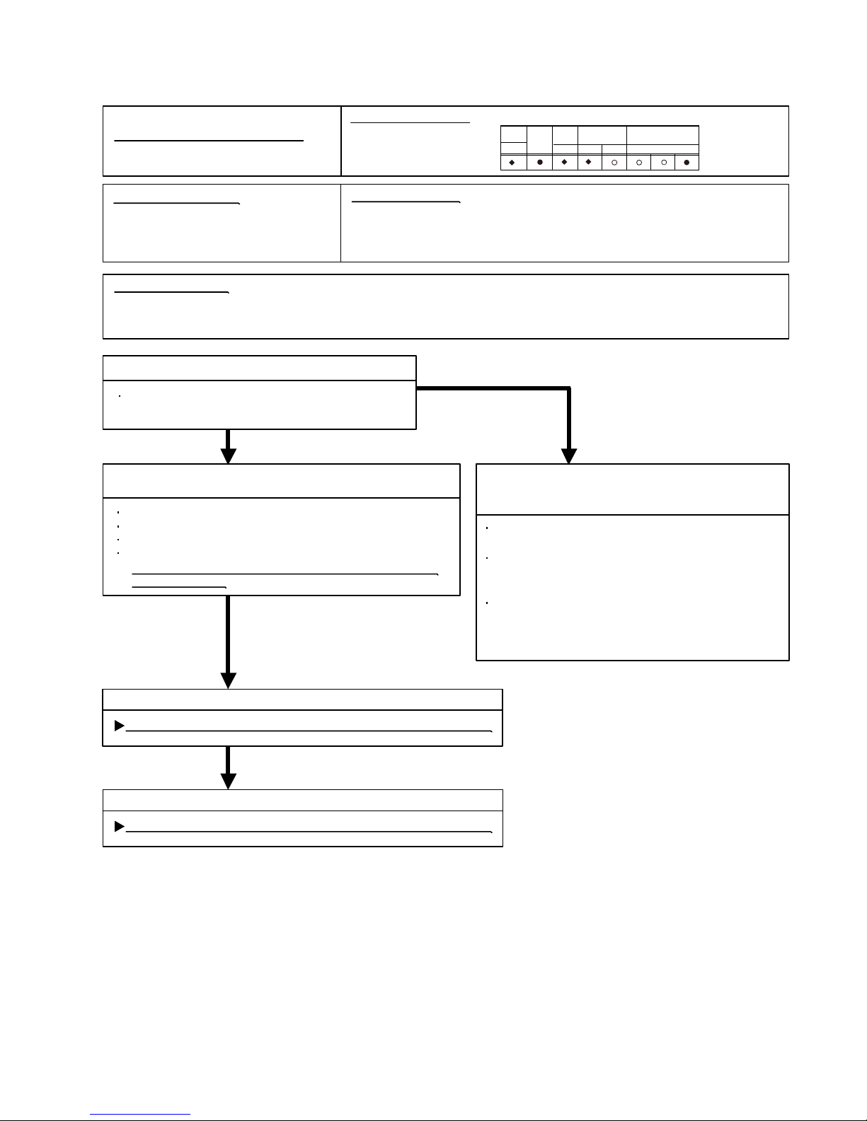
Trouble shooting 25
OUTDOOR UNIT Error Method:
Current S ensor Error
02-27
Detective Actuators:
Detective details:
Forecast of Cause :
Check Point 3 : Replace Filter PCB
YE S
NO
OK
OK
Outdoor unit Main PCB
Check Point 2 :
Check connections of Outdoor Unit Electrical Components
Check if connector is removed.
Check if
the terminal connection
is loose.
Check erroneous connection.
Check if cable is open.
>>Upon correcting the removed connector or mis-wiring,
reset the power.
Check Point 1-2 :
Check external cause at Indoor and Outdoor
(Voltage drop or Noise)
1. Defective connection of electric components 2 3. Filter PCB failure. External cause
4. Main PCB failure
Instant drop : Check if there is a large load electric
apparatus in the same circuit.
Momentary power failure : Check if there is a defective
contact or leak current in the
power supply circuit.
Noise : Check if there is any equipment causing harmonic
wave near electric line.(Neon bulb or electric
equipment that may cause harmonic wave)
Check the complete insulation of grounding.
Check Point 1-1 : Reset Power Supply and operate
Does Error indication show again?
When Input Current Sensor has detected 0A, while Inverter Compressor is
operating at higher than 56rps, after 1minute upon starting the Compressor.
(Except during the defrost operation)
If Check Point 1, 2 do not improve the symptom, change Filter PCB.
Check Point 4 : Replace Main PCB
If Check Point 3 do not improve the symptom, change Main PC B .
Indicate or Display:
Error code : 84
POWER
MODE
ERROR
2
8
)6L()2L()1L( (L5)(L4)(L3)
4
PUMP
DOWN
LOW
NOISE
PEAK
CUT
Outdoor unit : Model 45.54
Page 66
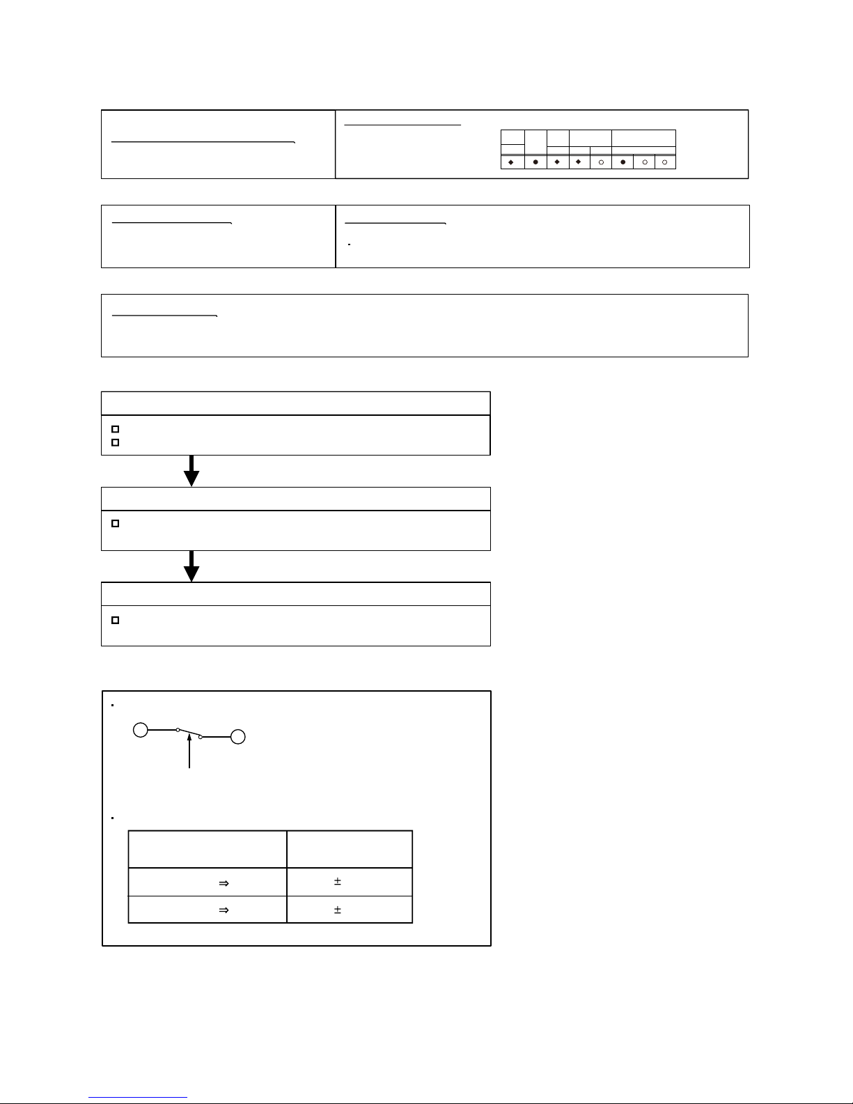
Trouble s hooting 26
OUTDOOR UNIT E rror Method:
OK
OK
Detective Actuators:
High pressure switch
Detective details :
Forecast of Cause :
1. High pressure switch connector disconnection, open
2. High pressure switch characteristics failure3. Main PCB failure
When the power was turned on, "high pressure switch : open" was detected.
Check Point 1 : Check the high pressure switch connection state
Connector and wiring connection state check
Cable open check
Check Point 2 : Check the high pressure switch characteristics
Switch characteristics check
* For the characteristics of high pressure switch, refer to below.
Check Point 3 : Replace Main PCB
Change Main PCB
, and execute the chec k operation again.
02-28
Pressure Sencer Error
Type of contact
Characteristics of pressure switch
C
H
Pressure
Pressure switch 1
4.2 0.1MPa
3.2 0.15MPa
Contact : Short Open
Contact : Open Short
(30/36:CN90,45/54:CN101)
POWER
MODE
ERROR
2
8
)6L()2L()1L( (L5)(L4)(L3)
6
PUMP
DOWN
LOW
NOISE
PEAK
CUT
Indicate or Display:
Error code : 86
Outdoor unit : Model 45.54
Page 67

02-29
Trouble s hooting 27
OUTDOOR UNIT E rror Method:
Over Current E rror
Detective Actuators:
Detective details:
Forecast of Cause :
OKOK
OKOK
Check Point 3: Replace Main PCB
Outdoor unit Main PCB
Compressor
Transistor PCB
If Chec k Point 1 or 1,2 do not improve the symptom, change Main PCB .
Check Point 2: Check Transistor PCB (IPM)
>> If IPM is abnormal, replace Transis tor PC B.
OKOK
Check Point 4: Replace Compressor
If Chec k Point 3 do not improve the symptom, change Compress or.
1. Outdoor unit fan operation defective, foreign matter on heat exchanger,
excessive rise of ambient temperature
2. Main PCB
3. Inverter compressor failure (lock, winding short)
4. Transistor PCB (IPM) failure
"
Protection stop
by overcurrent generation after inverter compressor start
processing completed'' generated consecutively 10 times.
* The number of generations is reset if the start-up of
the compressor succeeds.
No obstructions in air passages?
Heat exchange fins clogged
Outdoor unit fan motor check
Ambient temperature not raised by the effect of other heat sources?
Discharged air no
t sucked in?
Check Point 1 : Check the outdoor unit fan operation, heat exchanger, ambient temperature
Check IPM.
(PARTS INF ORMATIO N 7)
Indicate or Display:
Error code : 94
POWER
MODE
ERROR
2
9
)6L()2L()1L( (L5)(L4)(L3)
4
PUMP
DOWN
LOW
NOISE
PEAK
CUT
Outdoor unit : Model 45.54
Page 68

Trouble s hooting 28
OUTDOOR UNIT E rror Method:
Compressor Control Error
02-30
Detective Actuators:
Detective details:
Forecast of Cause :
Check Point 2 : Check connection of around the Compressor components
OKOK
Check Point 4: Replace Main PCB
Outdoor unit Main PCB
Compressor
Transistor PCB
1. Defective connection of electric components 2. Main PCB failure 3. Compressor failure
4. Transistor PCB (IPM) failure
If Chec k Point 1,2 or 1 3 do not improve the symptom, change Main PCB .
Check if connector is removed.
Check erroneous connection.
Check if cable is open.
>>Upon correcting the removed connec tor or mis-wiring, reset the power.
(Refer to PARTS INFORMATION 2)
For Compressor Terminal, Main PCB
While running the compressor, if the detected rotor location is out of
phase with actual rotor location more than 90°,
the compressor stops.
After the compressor restarts, if the same operation is repeated
within 40sec, the compressor stops again.
If and repeats 5 times, the compressor stops permanently.
Check Point 1 : Check Noise from Compressor
Turn on Power and check operation noise.
If an abnormal noise show, replace Compressor.
OKOK
Check Point 5: Replace Compressor
If Chec k Point 4 do not improve the symptom, change Compressor.
OKOK
OKOK
Check Point 3: Check Transistor PCB (IPM)
>> If IP M is abnormal, replace Transis tor PCB.
Check IPM.
(PARTS INF ORMATIO N 7)
Indicate or Display:
Error code : 95
POWER
MODE
ERROR
2
9
)6L()2L()1L( (L5)(L4)(L3)
5
PUMP
DOWN
LOW
NOISE
PEAK
CUT
Outdoor unit : Model 45.54
Page 69

02-31
Trouble shooting 29
OUTDOOR UNIT Error Method:
Detective Actuators:
Detective details:
Forecast of Cause:
Check Point 3 : Check Outdoor unit fan motor
OK
OK
Outdoor Unit Fan Motor 1 Error
Outdoor unit Main PCB
Outdoor unit fan motor
1. Fan rotation failure 2. Motor protection by surrounding temperature rise 3. Main PCB failure
4. Outdoor unit fan motor failure
Check Point 1 : Check rotation of Fan
Rotate the fan by hand when operation is off.
(Check if fan is caught, dropped off or locked motor)
>>If Fan or B earing is abnormal, replace it.
Check Outdoor unit fan motor.
(PA RTS INFO RMATIO N 5)
>>If Outdoor Fan Motor is abnormal, replace O utdoor fan motor and Main PCB .
Check Point 4 : Check Output Voltage of Main PCB
Check outdoor unit circuit diagram and the voltage. (Measure at Main PCB side connector)
If the voltage is not correct, replace Main PCB .
When outdoor fan rotation speed is less than 100rpm in 20 seconds
after fan motor starts, fan motor stops.
After fan motor restarts, if the same operation within 60sec is repeated
3 times in a row, compressor and fan motor stops.
If and repeats 5 times in a row, compressor and fan motor stops
permanently.
Read wire DC voltage
Red - Black
280V (AC220V-10%)
~ 373V (AC240+10%)
White - Black
15 1.5V
CN800
1
2
3
4
5
6
1
2
3
4
5
6
BLACK
WHITE
YELLOW
BROWN
RED
FM
Fan motor 1
(Upper)
Check Point 2 : Check ambient temp. around motor
OK
Check excessively high temperature around the motor.
(If there is any surrounding equipment that causes heat)
>>Upon the temperature coming down, restart operation.
Indicate or Display:
Error code : 97
POWER
MODE
ERROR
2
9
)6L()2L()1L( (L5)(L4)(L3)
7
PUMP
DOWN
LOW
NOISE
PEAK
CUT
Outdoor unit : Model 45.54
Page 70

02-32
Trouble shooting 30
OUTDOOR UNIT Error Method:
Detective Actuators:
Detective details:
Forecast of Cause:
Check Point 3 : Check Outdoor unit fan motor
OK
OK
Outdoor Unit Fan M
For Model 45/54
otor 2 Error
Outdoor unit Main PCB
Outdoor unit fan motor
1. Fan rotation failure 2. Motor protection by surrounding temperature rise 3. Main PCB failure
4. Outdoor unit fan motor failure
Check Point 1 : Check rotation of Fan
Rotate the fan by hand when operation is off.
(Check if fan is caught, dropped off or locked motor)
>>If Fan or B earing is abnormal, replace it.
Check Outdoor unit fan motor.
(PA RTS INFO RMATIO N 5)
>>If Outdoor Fan Motor is abnormal, replace O utdoor fan motor and Main PCB .
Check Point 4 : Check Output Voltage of Main PCB
Check outdoor unit circuit diagram and the voltage. (Measure at Main PCB side connector)
If the voltage is not correct, replace Main PCB .
When outdoor fan rotation speed is less than 100rpm in 20 seconds
after fan motor starts, fan motor stops.
After fan motor restarts, if the same operation within 60sec is repeated
3 times in a row, compressor and fan motor stops.
If and repeats 5 times in a row, compressor and fan motor stops
permanently.
Read wire DC voltage
Red - Black
280V (AC220V-10%)
~ 373V (AC240+10%)
White - Black
15 1.5V
Check Point 2 : Check ambient temp. around motor
OK
Check excessively high temperature around the motor.
(If there is any surrounding equipment that causes heat)
>>Upon the temperature coming down, restart operation.
Indicate or Display:
Error code : 98
POWER
MODE
ERROR
2
9
)6L()2L()1L( (L5)(L4)(L3)
8
PUMP
DOWN
LOW
NOISE
PEAK
CUT
CN802
1
2
3
4
5
6
1
2
3
4
5
6
BLACK
WHITE
YELLOW
BROWN
RED
FM
Fan motor 2
(Lower)
Outdoor unit : Model 45.54
Page 71

Detective Actuators :
Detective details:
Forecast of Cause :
OKOK
OKOK
1. Connector connection failure 2. Thermistor failure 3. Coil failure 4. 4-way valve failure
5. Main PCB failure
Check Point 1 : Check connection of Connector
Check if connector is removed.
Check erroneous connection.
Check if thermistor cable is open.
>> Upon correcting the removed connector or mis-wiring, reset the power.
Check Point 3 : Check the solenoid coil and 4-way valve
02-33
[ Solenoid coil ]
Remove 30/36:CN500,45/54:CN6 .lioc fo eulav ecnatsiser eht kcehc dna BCP morf
Resistance value is about 1.7k
>> If it is O pen or abnormal resistance value, replace Solenoid Coil.
[ 4-way valve ]
Check each piping temperature,
and the location of the valve by the temperature difference.
>> If the value location is not proper, replace 4-way valve.
OKOK
Check Point 4 : Replace Main PCB
If Check Point 1- 3 do not improve the symptom, replace Main PC B.
Check Point 2 : Check thermistor of Indoor unit
Isn’t it fallen off the holder?
Is there a cable pinched?
>> Check characteristics of thermistor, (Refer to Trouble s hooting 12,13),
If defective, replace the thermistor.
Indoor Unit Controller PCB Circuit
Heat Exchanger Temperature Thermistor
Room Temperature Thermistor
4-way valve
When the indoor heat exchanger temperature is compared with
the room temperature, and either following condition is detected
continuously two times, the compressor stops.
Cooling or Dry operation
[Indoor heat exchanger temp.] - [Room temp.] > 20°C
Heating operation
[indoor heat exchanger temp.] - [Room temp.] < -14°C
If the same operation is repeated 5 times,
the compressor stops permanently.
Trouble shooting 31
OUTDOOR UNIT Error Method:
4-Way Valve Error
Indicate or Display:
Error code : 99
POWER
MODE
ERROR
2
9
)6L()2L()1L( (L5)(L4)(L3)
9
PUMP
DOWN
LOW
NOISE
PEAK
CUT
Outdoor unit : Model 45.54
Page 72

<Cooling operation>
OK
OK
OK
OK
:
OK
<Heating operation>
2. EEV defective, strainer clogged
3. Outdoor unit operation
failure
, foreign matter on heat exchanger
4. Discharge temperature thermistor
failure
5. Insufficient refrigerant
Discharge temperature thermistor
"Protection stop by "discharge temperature 115
°C
during compressor
.sruoh42nihtiwsemit2detareneg''''noitarepo
Check Point 1 : Check if 3-way valve(gas side) is open.
Discharger thermistor characteristics check
(Check by disconnecting thermistor from PCB.)
* For the characteristics of the thermistor, refer to the "Service Parts Information 8".
Check Point 4 : Check the discharge thermistor
EEV open?
Strainer clogging check (before and after EEV, ACM
oil return)
Refer to "Service Parts Information 3, 4 "
Check Point 3 : Check the outdoor unit fan,heat exchanger
Check for foreign object at heat exchanger
Check if fan can be rotated by hand.
Motor check(PARTS INFORMATION 5)
Check Point 2 : Check the EEV, strainer
Check Point 5 : Check the refrigerant amount
Leak check
EEV open?
Strainer clogging check (before and after EEV, ACM
oil return)
Refer to "Service Parts In
formation 3"
Check Point 2 : Check the EEV, strainer
If the 3-way valve(gas side) was closed, open the
3-way valve(gas side) and check operation.
02-34
Check Point 1 : Check if 3-way valve(liquid side) is open.
If the 3-way valve(liquid side) was closed, open the
3-way valve(liquid side) and check operation.
OK
1. 3-way valve not opened
Detective Actuators:
Detective details:
Forecast of Cause :
Trouble s hooting 32
OUTDOOR UNIT E rror Method:
Discharge Temp. Error
Indicate or Display:
Error code : A1
POWER
MODE
ERROR
2
10
)6L()2L()1L( (L5)(L4)(L3)
1
PUMP
DOWN
LOW
NOISE
PEAK
CUT
Outdoor unit : Model 45.54
Page 73

Compressor Temp. E rror
OK
OK
OK
OK
1. 3-way valve not opened
2. EEV defective, strainer clogged
3. Outdoor unit operation
failure
, foreign matter on heat exchanger
4. Compressor temperature thermistor
failure
5. Insufficient refrigerant
Compressor temperature thermistor
Compressor temperature thermistor characteristics check
(Check by disconnecting thermistor from PCB)
* For the characteristics of the thermistor, refer to the "Service Parts Information 8.
Check Point 4 : Check the compressor temperature thermistor
Check Point 3 : Outdoor unit fan, heat exchanger check
Check for foreign object at heat exchanger
Check if fan can be rotated by hand.
Motor check(PARTS INFORMATION 5)
Check Point 5 : Check the refrigerant amount
Leak check
02-35
<Cooling operation>
OK
<Heating operation>
Check Point 1 : Check if 3-way valve(gas side) is open.
EEV open?
Strainer clogging check (before and after EEV, ACM
oil return)
Refer to "Service Parts Information 3".
Check Point 2 : Check the EEV, strainer
EEV open?
Strainer clogging check (before and after EEV, ACM
oil return)
Refer to "Service Parts Information 3".
Check Point 2 : Check the EEV, strainer
If the 3-way valve(gas side) was closed, open the
3-way valve(gas side) and check operation.
Check Point 1 : Check if 3-way valve(liquid side) is open.
If the 3-way valve(liquid side) was closed, open the
3-way valve(liquid side) and check operation.
OK
"Protection stop by "compressor temperature" 110°C during compressor
operation""generated 2 times within 24 hours
Trouble s hooting 33
Detective Actuators:
Detective details:
OUTDOOR UNIT E rror Method:
Forecast of Cause :
Indicate or Display:
Error code : A3
POWER
MODE
ERROR
2
01
)6L()2L()1L( (L5)(L4)(L3)
3
PUMP
DOWN
LOW
NOISE
PEAK
CUT
Outdoor unit : Model 45.54
Page 74

Trouble shooting 34
OUTDOOR UNIT E rror Method:
Low Pressure Error
Detective Actuators:
Detective details:
Forecast of Caus e :
OK
1. 3-way valve not opened 2. Outdoor unit ambient temperature too low
3. Outdoor unit fan operation defective, foreign matter at heat exchanger
4. EEV defective, strainer clogged 5. Solenoid valve defective
6. Pressure sensor characteristics defective 7. Insufficient refrigerant
Pressure sensor
"Protection stop by suction pressure 0.02MPaG continued for 5 minutes"
repeats 5 times within 2 hours.
No foreign object in air passage?
Heat exchange fins clogged
Fan rotates?
Outdoor unit fan motor check
Check Point 3 : Check the outdoor unit fan operation,
heat exchanger
Check Point 2 : Check the outdoor unit ambient temperature
Outdoor ambient temperature lower than operating range?
Outdoor unit EEV operation check
Strainer not clogged?
Check Point 4 : Check the outdoor unit EEV, strainer clogging
Indoor unit EEV operation check
Strainer not clogged?
strainer
Pressure sensor characteristics check
* For the characteristics of the suction pressure sensor
(PARTS INFORMATION 9)
Check Point 6 : Check the suction pressure sensor
Check Point 7 : Check the refrigerant amount
Leak check
02-36
>noitarepo gnitaeH<>noitarepo gnilooC<
Check Point 1 : Check if 3-way valve(gas side) is open.
If the 3-way valve(gas side) was closed, open the
3-way valve(gas side) and check operation.
Check Point 1 : Check if 3-way valve(liquid side) is open.
If the 3-way valve(liquid side) was closed, open the
3-way valve(liquid side) and check operation.
OK
OK
OK
OK
OK
Refer to "Service Parts Information 3"
Indicate or Display:
Error code : A5
POWER
MODE
ERROR
2
10
)6L()2L()1L( (L5)(L4)(L3)
5
PUMP
DOWN
LOW
NOISE
PEAK
CUT
Outdoor unit : Model 45.54
Attention!!
30/36 units do not have the pressure sensor.
In this case, replace
the Main PCB.
Refer to "Service Parts Information 3"
Check
Page 75
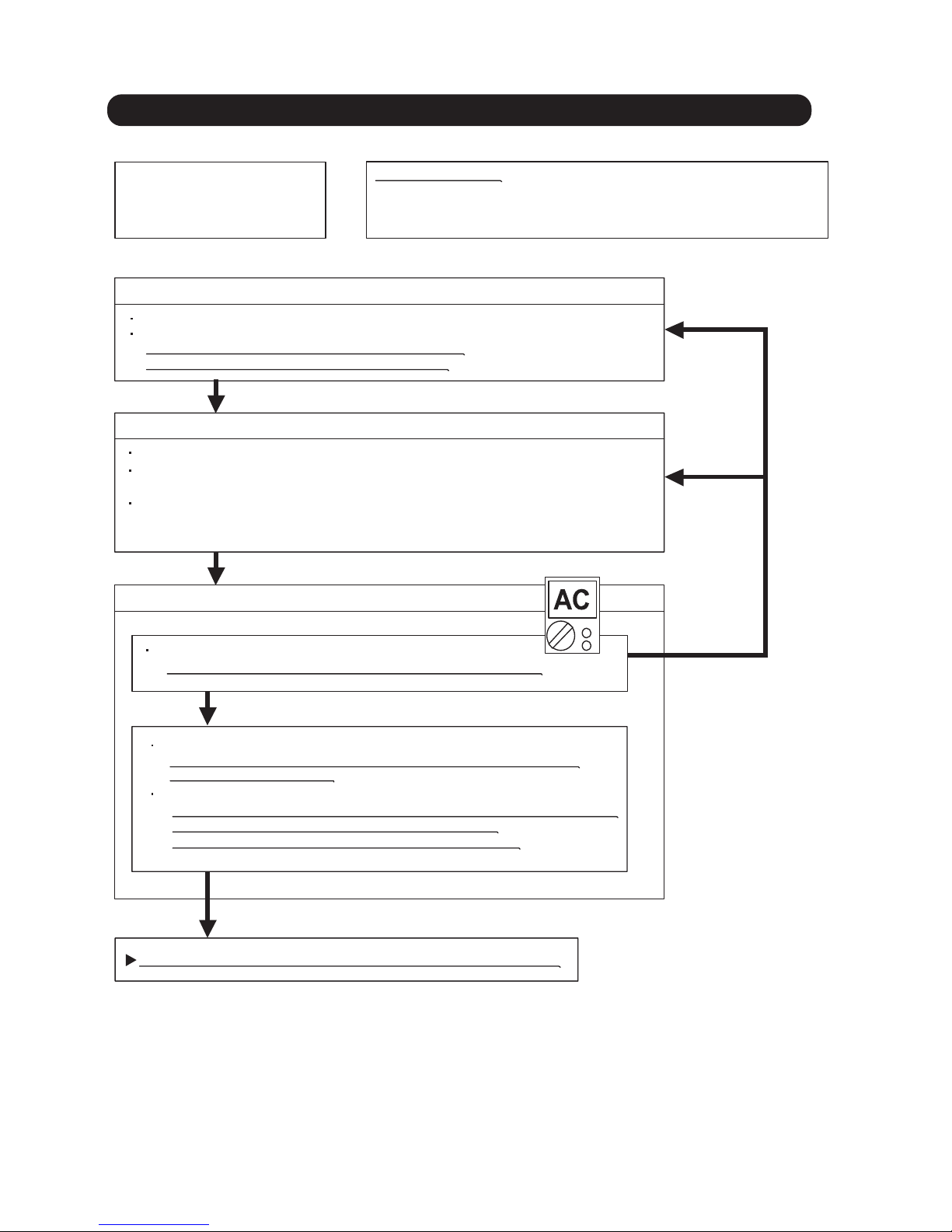
Trouble s hooting 35
Forecast of Cause:
OKOK
Indoor Unit - No Power
1. Power Supply failure 2. External cause
3. Electrical Components defective
Check Point 1 : Check Installation Condition
Isn’t the breaker down?
Check loose or removed connection cable.
>>If abnormal condition is found, correct it by referring
to Installation Manual or Data & Technical Manual.
Check Point 2 : Check external cause at Indoor and Outdoor (Voltage drop or Noise)
Instant drop ----- Check if there is a large load electric apparatus in the same circuit.
Momentary power failure ----- Check if there is a defective contact or leak current in
the power supply circuit.
Noise ----- Check if there is any equipment causing harmonic wave near electric line.
(Neon bulb or electric equipment that may cause harmonic wave)
Check the complete insulation of grounding.
02-37
2-3 TROUBLE SHOOTING WITH NO ERROR C ODE
Check Point 3 : Check Electrical Components
YE SYE S
OK
NO
Check the voltage of power supply.
>> C heck if AC 198 - 264V appears at Outdoor Unit Terminal L - N.
Check Varistor in Filter PCB.
>> If Varistor is defective, there is a possibility of an abnormal power s upply.
Check the correc t power supply and replace Varistor.
Upon checking the normal power supply, replace Varistor.
If the symptom does not change by above Check 3, replace Main PCB.
OK
Check Fuse in Filter PCB.
>> If Fus e is open, check if the wiring between Terminal and F ilter P CB
is loos e, and replace Fuse.
Page 76
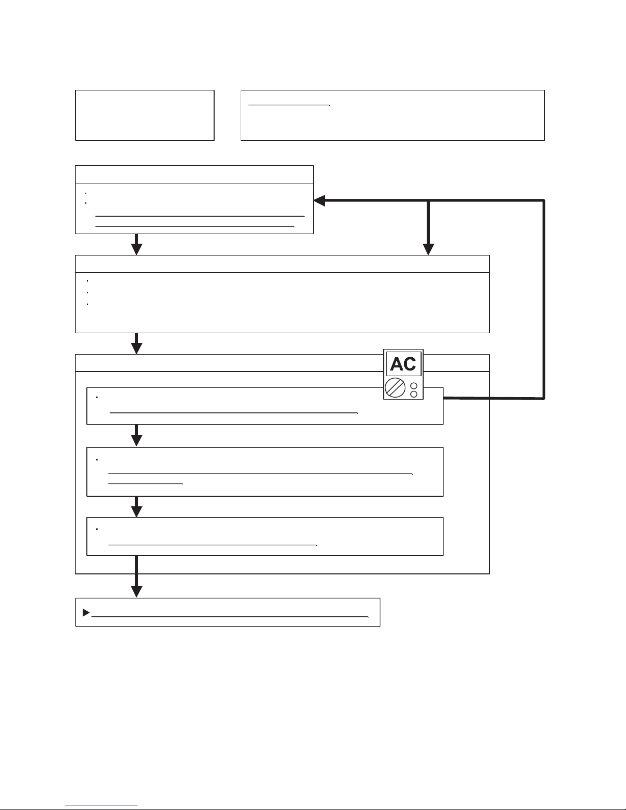
Trouble s hooting 36
Forecast of Cause:
Check Point 3 : Check Electrical Components
OKOK
OKOK
YE SYE S
YE SYE S
OK
NO
Check Point 1 : Check Installation Condition
Outdoor Unit - No Power
1. Power Supply failure 2. External cause
3. Electrical Components defective
Isn’t the breaker down?
Check loose or removed connection cable.
>>If abnormal condition is found, correct it by referring
to Installation Manual or Data & Technical Manual.
Check Point 2 : Check external cause at Indoor and Outdoor (Voltage drop or Noise)
Instant drop ----- Check if there is a large load electric apparatus in the same circuit.
Momentary power failure ----- Check if there is a defective contact or leak current in the power supply circuit.
Noise ----- Check if there is any equipment causing harmonic wave near electric line.
(Neon bulb or electric equipment that may cause harmonic wave)
Check the complete insulation of grounding.
Check the voltage of power supply.
>> C heck if AC 198 - 264V appears at Outdoor Unit Terminal L - N.
Check Fuse in Main PCB.
>> If Fus e is open, check if the wiring between Terminal and Main PC B is loose,
and replace Fuse.
Check Active Filter Module and IPM.
(P ARTS INFORMATION 6 and 7)
>> If Active Filter Module or IPM is abnormal, replace it.
If the symptom does not change by above Chec k 3, replace Main P CB.
02-38
Page 77

Trouble s hooting 37
Forecast of Cause:
Check Point 2 : Check external cause at Indoor and Outdoor (Voltage drop or Noise)
Check Point 1 : Check indoor and outdoor installation condition
Check Point 3 : Check Wired Remote Controller and Controller PCB
OK
OK
OKOK
No Operation (Power is ON)
1. Setting/ Connection failure 2. External cause
3. Electrical Component defective
Indoor Unit - Check incorrect wiring between Indoor Unit - Remote Control.
Or, check if there is an open cable connection.
Are these Indoor Unit, Outdoor Unit, and Remote Control suitable model numbers to connect?
>> If there is some abnormal condition, correct it by referring to Installation manual and
Data & Technical
Manual.
Turn off Power and check/ correct followings.
Is there loose or removed communication line of Indoor Unit and Outdoor Unit?
Instant drop ----- Check i
f there is a large load electric apparatus in the same circuit.
Momentary power failure ----- Check if there is a defective contact or leak current in the power supply circuit.
Noise ----- Check if there is any equipment causing harmonic wave near electric line
.
(Neon bulb or electric equipment that may cause harmonic wave)
Check the complete insulation of grounding.
>> If it is DC13V, Remote Control is failure. (C ontroller PC B is normal) >> Replace R emote Control
>> If it is DC 0V, Controller PCB is failure. (Check Remote Control once again) >> Replace Controller PCB
>> If the symptom does not change by above Check 1, 2, 3, replace Main PC B of O
utdoor unit.
02-39
Check Voltage at CN14 of Controller PCB. (terminal 1-3)
(Power supply to Remote Control)
Page 78

Attention
Trouble s hooting 38
Forecast of Cause:
Check Point 2 : Check Outdoor Unit Operation
Check Point 1 : Check Indoor Unit
Check Point 3 : Check Site Condition
Check Point 5 : Check Refrigeration Cycle
Check Point 4 :
Check Indoor/ Outdoor Installation Condition
)tuO( epiP)nI( epiP
)tuO( epiP)nI( epiP
OKOK
OKOK
OKOK
OKOK
MPa MPa
No Cooling / No Heating
1. Indoor Unit error 2. Outdoor Unit error
3. Effect by Surrounding environment
4. Connection Pipe / Connection Wire failure 5. Refrigeration cycle failure
Does Indoor Unit FAN run on HIGH FAN?
Is Air Filter dirty?
Is Heat Exchanger clogged?
Check if Energy save function is operated.
Check if Outdoor Unit is operating
Check any objects that obstruct the air flow route.
Check clogged Heat Exchanger.
Is the Valve open?
Is capacity of Indoor Unit fitted to Room size?
Any windows open? Or direct sunlight ?
Check connection pipe
(specified pipe length & Pipe diameter?)
Check any loose or removed communication line.
>> If there is an abnormal condition, correct it by
referring to Installation Manual or Data & Technical
Manual.
Check if Strainer is clogged (Refer to the figure at right).
Measure Gas Pressure and if there is a leakage, correct it.
>> When recharging the refrigerant, make sure to perform
vacuuming, and recharge the specified amount.
Check EEV (PARTS INFORMATION 3)
Check Compressor (PARTS INFORMATION 1,2)
Strainer normally does not have temperature difference
between inlet and outlet as shown in , but if there is a
difference like shown in , there is a possibility of inside
clogged. In this case, replace Strainer.
02-40
Page 79

Trouble s hooting 39
Forecast of Cause :
Trouble s hooting 40
Forecast of Cause:
OK
OK
OK
OK
OKOK
OKOK
OKOK
MPa MPa
Abnormal Noise
1. Abnormal installation (Indoor/ Outdoor)
2. Fan failure (Indoor/ Outdoor)
3. Compressor failure (Outdoor)
Diagnosis method when Abnormal Noise is occurred
Abnormal noise is coming from Indoor Unit.
(Check and correct followings)
Abnormal noise is coming from Outdoor Unit.
(Check and correct followings)
Is Fan broken or deformed?
Is the screw of Fan loose?
Is there any object which obstruct the Fan rotation?
Is Main Unit installed in stable condition?
Is the installation of Air suction grille and
front panel normal?
Is Fan broken or deformed?
Is the screw of Fan loose?
Is there any object which obstruct the Fan rotation?
Is Main Unit installed in stable condition?
Is Fan Guard installed normally?
Check if vibration noise by loose bolt or contact noise
of piping is happening.
Is Compressor locked?
>> Check Compressor (PARTS INFORMATION 1,2)
Water Leaking
1. Erroneous installation 2. Drain hose failure
Diagnosis
method when water is spitting out.
Is the filter clogged?
Check Gas Pressure and correct it
if there was a gas leak.
Diagnosis method when water leak occurs
Is Drain Hose connection loose?
Is there a trap in Drain Hose?
Is Drain Hose clogged?
Is Main Unit installed in stable condition?
Is Main Unit broken or deformed at the time of
transportation or maintenance?
Is Fan rotating?
02-41
Page 80
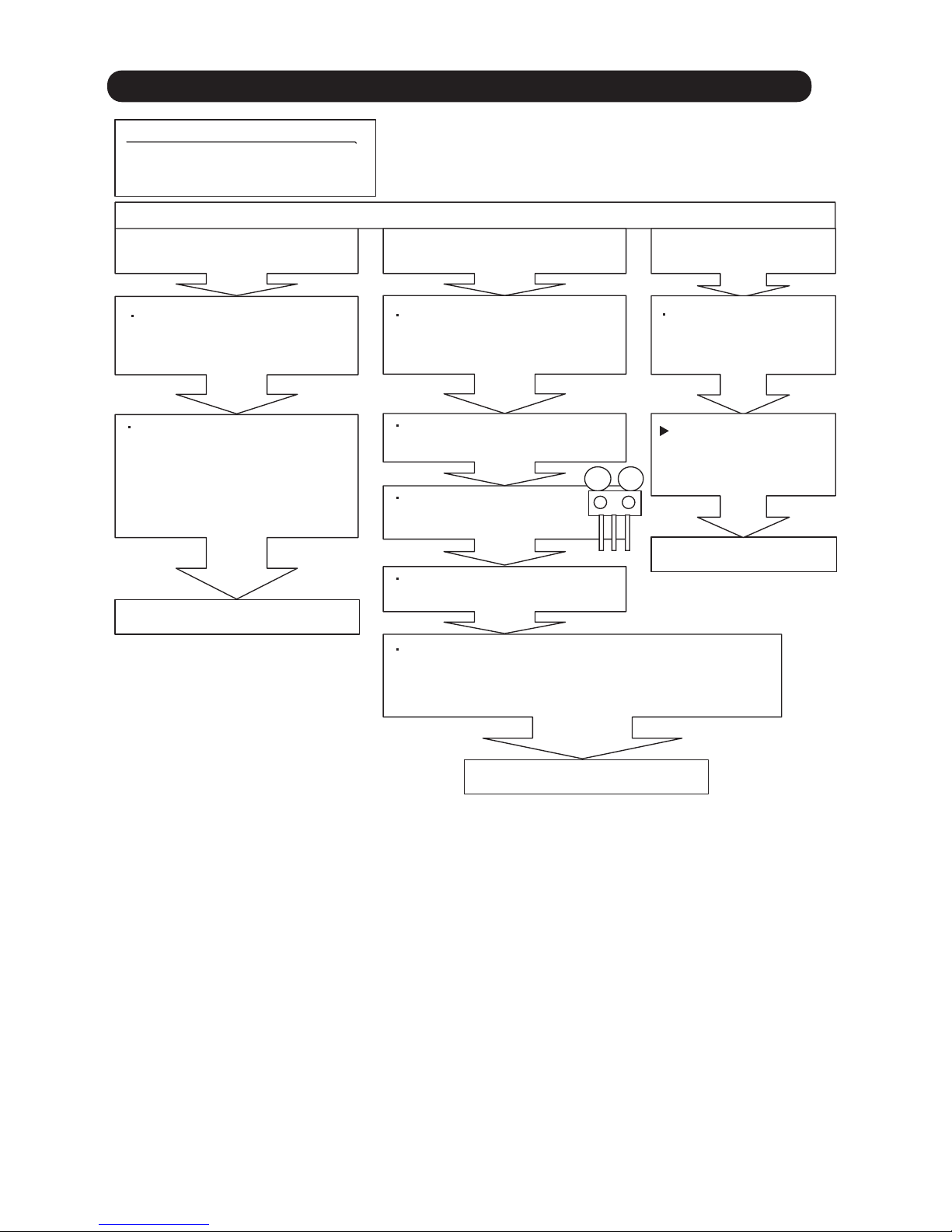
SE RVICE PARTS INFORMATION 1
MPa MPa
Compressor
Diagnosis method of Compressor ( If Outdoor Unit LED displays Error, refer to Trouble shooting )
Does not start up
Is there open or loose connection
cable?
Check Main PCB, connection of
Compressor, and winding resistance.
(Refer to the next page).
Check Main PCB, connection of Compressor,and winding
resistance. (Refer to the next page).
>> If there is no failure, the defect of
Compressor is cons idered (Locked
compressor due to clogged dirt or
less oil)
Replace Compressor
Replace Compressor
Replace Compressor
Stops soon after starting up
Is there open or loose connection
cable?
Is Gas Pipe Valve open?
(Low Pressure is too low)
Check if Refrigerant is leaking.
(Recharge Refrigerant
)
Check if Strainer is clogged.
(PARTS INFORMATION 3)
>> If there is no failure, the defect of Compressor can be
considered. (Compression part broken or valve defective.)
Abnormal noise
Defective Compressor
can be cons idered.
(due to inside dirt clogging
or broken component)
Check if vibration noise by
loose bolt or contact noise
of piping is happening.
02-42
2-4 SERVICE PARTS INFORMATION
Page 81

SE RVIC E PARTS INFORMATION 2
Check Point 1 : Check Connection
Check Point 2 : Check Winding Resistance
Check Point 3 : Replace Main PCB
U
V
W
Inverter Compressor
Check terminal connection of Compressor
(loose or incorrect wiring)
Check winding resistance of each terminal
If the resistance value is 0 or infinite, replace Compressor.
If the symptom does not change with above Check 1, 2, replace Main PC B.
02-43
Resistance Value :
U
(RED)
V
(WHITE)
W
(BLACK)
Transistor PC B
TM303
(W)
TM304
(V)
TM305
(U)
RED
WHITE
BLACK
Compressor
Inverter P CB
0.43
at 20°C (45/54)
0.64
at 20°C (30/36)
Page 82

SE RVIC E PARTS INFORMATION 3
Check Point 2 : Check Coil of EEV
Yellow - Red
Orange - Red
Blue - Red
White - Red
Read wire
46 4
Resistance value
Check Point 1 : Check Connections
Check Point 5 : Check Opening and Closing Operation of Valve
Check Point 4 : Check Voltage from Main PCB.
Check Point 3 : Check Noise at start up
Pipe (In)
Pipe (Out)
Pipe (In)
CLOSE
Example : Hot G as
OPEN
Example : Hot G as
Pipe (Out)
)tuO( epiP)nI( epiP
)tuO( epiP)nI( epiP
Check Point 6 : Check Strainer
DC
at 68°F(20°C)
Outdoor unit Electronic Expansion Valve
( EEV )
C
]45/54[]63/03[
heck connection of connector
( Loose connector or open cable )
Remove connector, check each winding
resistance of Coil.
If Resis tance value is abnormal, replace EEV.
Remove Connector and check Voltage (DC12V)
If it does not appear, replace Main PC B .
Turn on Power and check operation noise.
If an abnormal noise does not s how,
replace Main PC B.
When Valve is closed,
it has a temp. difference between Inlet and Outlet.
If it is open,
it has no temp. difference between Inlet and Outlet.
Strainer normally does not have temperature difference between inlet and outlet as shown in ,
but if there is a difference as shown in , there is a possibility of inside clogged. In this case, replace Str
ainer.
02-44
CN700
EXPANSI ON
VALVE COIL
EV
RED
BLUE
ORANGE
YELLOW
WHITE
1
2
3
4
5
1
2
3
4
5
CN111
EXPANSION
VALVE COIL
EV
RED
BLUE
ORANGE
YELLOW
WHITE
1
2
3
4
5
6
Page 83

SE RVICE PARTS INFORMATION 5
Check Point 1 : Check rotation of Fan
Outdoor unit fan motor
Rotate the fan by hand when operation is off.
(Check if fan is caught, dropped off or locked motor)
>>If Fan or Bearing is abnormal, replace it.
Check Point 2 : Check resistance of Outdoor Fan Motor 1 or 2
Refer to below. Circuit-test "Vm" and "GND" terminal
[45/54][30/36]
.
Check resistance when the main power supply is OFF.
(Vm: DC voltage, GND: Earth terminal)
>>If they are short-circuited (below 300 k ), replace Outdoor fan motor and Main PC B.
Pin number
(wire color)
Terminal function
(symbol)
1 (Red)
2
3
4 (Black)
5 (White)
6 (Yellow)
DC voltage (Vm)
No function
No function
Ground terminal (GND)
Control voltage (Vcc)
7 (Brown)
Speed command (Vsp)
Pin number
(wire color)
Terminal function
(symbol)
1 (Red)
2
3 (Black)
4 (White)
5 (Yellow)
DC voltage (Vm)
No function
Earth terminal (GND)
Control voltage (Vcc)
Speed command (Vsp)
6 (Brown) Feed back (FG)
Feed back (FG)
SE RVICE PARTS INFORMATION 4
Check Point 1 : Check rotation of Fan
Indoor unit fan motor
Rotate the fan by hand when operation is off.
(Check if fan is caught, dropped off or locked motor)
>>If Fan or Bearing is abnormal, replace it.
Check Point 2 : Check resistance of Indoor Fan Motor
Check resistance when the main power supply is OFF.
02-45
Refer to below. Circuit-test "Vm" and "GND" terminal.
(Vm: DC voltage, GND: Ground terminal)
>>If they are short-circuited (below 300 k ), replace Indoor fan motor and Controller PCB.
Pin number
(wire color)
Terminal function
(symbol)
1 (Red)
2
3
4 (Black)
5 (White)
6 (Yellow)
7 (Brown)
DC voltage (Vm)
No function
No function
Earth terminal (GND)
Control voltage (Vcc)
Speed command (Vsp)
Feed back (FG)
Page 84

02-46-
SE RVICE PARTS INFORMATION 6
Active filter module
Check Point 1 : Check Open or Short-circuit and Diode (D1)
Check Point 2 : Check the Output DC voltage (between P and N)
L2L1
P
Check the Output DC voltage (between P and N) of compressor stopping and operating.
If it is abnormal,replace ACTIVE F ILTER MODUL E
Remove connector, check the open or short-circuit and the diode in the module
>> If the output voltage of compressor operating is less than the output voltage of compressor stopping,
Active Filter Module is detective. >>
Replace Ac tive Filter Module
Check the open or short-circuit
Terminal
Resistance value
L2
L1
L1 , L2
P
P
Control Box
N1 (N)
*
+ (+IN)*
- ( -IN)*
- ( -IN)*
multimeter
(-)
N1 (N)*
L2
0
360k
720k
1.65M /
20%
+
-
360k
20%
+
-
20%
+
-
(Ref. value 1)
1.14M
(Ref. value 2)
1.01M /
(Ref. value 1)
0.76M
(Ref. value 2)
SACT32010 [ HITACHI ]
LACT33020 [ HITACHI ]
PM-604 [ FGEL ]
PM-703 [ FGEL ]
PM-601 [ FGEL ]
360k
20%
+
-
0
900k
20%
+
-
1.01M /
(Ref. value 1)
0.76M
(Ref. value 2)
540k
20%
+
-
1.65M /
(Ref. value 1)
1.14M
(Ref. value 2)
LO T No. 1302931396 -
LO T No. - 1302931395
PM-601 [ FGEL ]
B epyTA epyT
Table.1 Each type standard value
multimeter
(+)
+ (+IN)*
N1 (N)*
+ (+IN)*
- ( -IN)*
N1 (N)*
* ( ) is FGEL terminal name.
L2
P
P
L2
Terminal
Resistance value
1.32M /
(Ref. value 1)
0.66M
(Ref. value 2)
1.01M /
(Ref. value 1)
0.76M
(Ref. value 2)
Table.2 Standard value is changed by the tool specification
(Type A and B are the same value)
multimeter
(-)
multimeter
(+)
By kind of multimeter , the value may change significantly.
Ref. value 1
Specifications for Multimeter
Manufacturer : FL UKE
Model name : FLUKE11
Power source : DC9V.
Ref. value 2
Specifications for Multimeter
Manufacturer : SA NWA
Model name : PM3
Power source : DC3V.
LOT No. of PM-601 [ FGE L ] type
Model name
Lot No.(10 figures)
Label position
Label
Page 85

SE RVICE PARTS INFORMATION 7
IPM
(
Mounted on Transistor PCB)
02-47
Check Point 1
Check Point 2
Terminal
Resistance value
Tester(+) Tester(-)
Disconnect the connection wires between the Transistor PCB - Capacitor PCB
and Transistor PCB - Inverter Compressor.
Set the tester to the "Resistance" mode, and measure
the resistance between the following terminals.
Set the tester to the "Diode" mode, and measure
the voltage value between the following terminals.
Judge the result of as follows:
Judge the result of as follows:
TM301 (P) - TM305(U) / TM304(V) / TM303(W)
TM302 (N) - TM305(U) / TM304(V) / TM303(W)
P
U
V
W
N
U
V
W
U
V
W
P
U
V
W
N
Over 2k
(Including )
Over 2k
(Including )
Over 20k
(Including )
Terminal
Tester display
Tester(+) Tester(-)
P
U
V
W
N
U
V
W
U
V
W
P
U
V
W
N
0.3V 0.7V
P
YELLOW
TM301
U
RED
V
W
WHITE
BLACK
N
BLUE
TM305
TM304
TM303
TM302
W305
W304
W303
W302
CN301
IPM CONTR OL WHITE
CN303
WHITE
W301
Page 86

SE RVICE PARTS INFORMATION 8
Thermistor
02-48
Check Point : Check Thermistor resistance value
Remove connector and check Thermistor resistance value.
Temperature
[°C]
Resistance Value [ k ]
Thermistor A Thermistor B Thermistor C Thermistor D
- 20
- 10
- 5
0
5
10
15
20
25
30
40
50
60
70
80
90
100
110
120
---
---
---
168.6
129.8
100.9
79.1
62.6
49.8
40.0
26.3
17.8
12.3
8.7
6.3
4.6
3.4
2.6
2.0
---
27.8
21.0
16.1
12.4
9.6
7.6
6.0
4.8
3.8
2.5
1.7
1.2
---
---
---
---
---
---
105.4
58.2
44.0
33.6
25.9
20.2
15.8
12.5
10.0
8.0
5
.3
3.6
---
---
---
---
---
---
---
-
--
27.4
20.7
15.8
12.2
9.5
7.5
5.9
4.7
3.8
2.5
1.7
1.2
0.8
0.6
0.4
0.3
---
---
Applicable
Thermistors
Discharge temp. TH
Compressor temp. TH
Outdoor temp. TH Heat sink temp. THHeat exchanger. TH
SE RVICE PARTS INFORMATION 9
Pressure S ensor
Check Point : Check Voltage from Main PCB
DC
With the connector connected to the PCB, measure the voltage between CN91:3-4
of the Main PCB.
Characteristics of pressure sensor
4.5
5.0
0.5
0
Output [DCV]
Pressure [MPa]
DC
1 1
3 3
WHITE
PR ESSURE
SE NSOR
(HIGH )
BLACK
2 2
RED
PS
CN91
4
4
2.5
2.5
Page 87

3-3-17,Suenaga,Takatsu-ku,Kawasaki 213-8502,Japan
Aug. 2015 Printed in Japan
 Loading...