

Page 1
Large Capacity Multi VRF System
DC Inverter Control Compressor
Long Piping System Design
High Efficiency Refrigerant R410A
Multi Air Conditioning System for Buildings
SERVICE MANUAL
Page 2

CONTENTS
1. TEST RUN
1-3 CHECK ITEMS AFTER POWER ON..........................................................................
1-2-1 Power source Inspection......................................................................................
1-2-2 Outdoor unit field setting inspection.....................................................................
1-2 CHECK ITEMS BEFORE POWER ON.......................................................................
1-1 EXECUTION PROCEDURE AND EXECUTION PRECAUTIONS..............................
1-2-4 Transmission wire installation inspection..............................................................
01-01
01-03
01-03
01-04
01-05
1-2-3 Indoor unit field setting inspection........................................................................ 01-04
01-09
1-4 TEST RUN OPERATION........................................................................................... 01-13
2-1 REFRIGERANT CIRCUIT..........................................................................................
2. OUTDOOR UNIT OPERATION CONTROL
2-2 INPUT / OUTPUT LIST...............................................................................................
02-01
02-03
02-04
02-06
2-3-4 Compressor Sequence Operation.......................................................................
2-3-3 Capacity control...................................................................................................
2-3-1 Operation / Stop Condition..................................................................................
02-07
2-6 SPECIAL OPERATION...............................................................................................
02-11
02-11
02-11
2-6-2 Pre-Heat Operation.............................................................................................
2-6-1 Oil Recovery Operation.......................................................................................
2-6-3 Defrost Operation Control....................................................................................
02-12
2-4 FAN CONTROL..........................................................................................................
02-08
2-5 EXPANSION VALVE CONTROL...............................................................................
02-10
02-08
02-14
2-6-4 Low noise mode...................................................................................................
2-4-1 Cooling operation.................................................................................................
02-09
2-4-2 Heating operation.................................................................................................
1-2-5 Piping installation inspection................................................................................. 01-07
1-2-6 Refrigerant charge amount inspection.................................................................. 01-08
1-2-7 3-way valve opening inspection........................................................................... 01-08
1-3-1 Power source check.............................................................................................
1-3-2 Error indication check...........................................................................................
1-3-4 Transmission line connection check.....................................................................
01-09
01-09
01-11
1-3-3 Installed unit and their addresses check.............................................................. 01-10
1-3-5 Operation check sheet......................................................................................... 01-12
1-4-1 Test Run From Outdoor unit PC Board................................................................
1-4-2 Test Run From Remote Controller.......................................................................
01-13
01-14
1-5 TEST RUN CONTROL...............................................................................................
01-17
1-6 FIELD SETTING / FUNCTION SETTING FOR OUTOOR UNIT...............................
01-18
1-7 FIELD SETTING / FUNCTION SETTING FOR INOOR UNIT...................................
01-21
1-8 FIELD SETTING / FUNCTION SETTING FOR OUTDOOR AIR UNIT......................
01-22
2-3 COMPRESSOR OPERATION.................................................................................... 02-04
02-05
2-3-2 Compressor speed control..................................................................................
02-152-6-5 Snow Falling Protection Fan Mode -Default Setting -..........................................
Page 3

CONTENTS
3-2 MASTER CONTROL..................................................................................................
3-1-2 "AUTO" Position..................................................................................................
3-1-1 Fan Speed Setting...............................................................................................
3-1 FAN CONTROL..........................................................................................................
3. INDOOR UNIT AND RB UNIT OPERATION
3-2-1 Operation Mode Control......................................................................................
3-2-2 Operation Mode Control for Outdoor air unit.......................................................
03-01
03-01
03-01
03-02
03-02
03-04
3-3 LOUVER CONTROL..................................................................................................
3-2-3 Auto Changeover................................................................................................
03-06
3-2-5 "COOL" Position.................................................................................................. 03-08
03-08
3-2-4 Auto Changeover Heating / Cooling Operation for Outdoor air unit ................... 03-07
03-10
3-5 DRAIN PUMP OPERATION.......................................................................................
3-4 ELECTRONIC EXPANSION VALVE CONTROL......................................................
3-6 FUNCTION..................................................................................................................
03-13
03-15
03-16
3-6-1 Auto Restart.........................................................................................................
03-16
3-6-2 Icing Protection Control.......................................................................................
03-16
3-6-3 Oil Recovery Operation....................................................................................... 03-16
3-6-4 Outdoor temperature protected operation for Outdoor air unit ...........................
03-17
3-7 DX KIT........................................................................................................................
03-18
3-7-1 System Configuration..........................................................................................
03-18
3-7-2 Fundamental Functions...................................................................................... 03-19
3-7-3 Fundamental Functions....................................................................................... 03-20
2-7 PROTECTIVE FUNCTION.........................................................................................
02-16
02-16
2-7-1 Discharge temperature protection.......................................................................
02-18
2-7-2 High pressure protection.....................................................................................
02-20
2-7-3 Low pressure protection......................................................................................
02-21
2-7-4 Heatsink temperature protection.........................................................................
02-21
2-7-5 Compressor temperature protection....................................................................
02-21
2-7-6 O.U Heat - Ex.1(2) Gas Temp. abnormal stop....................................................
02-22
2-7-7 Over current protection........................................................................................
02-22
2-7-8 Compressor Frequency Maximum setting protection..........................................
02-22
2-7-9 Compressor compress ratio protection................................................................
02-232-7-10 Fan Motor, Motor Driver abnormal stop protection............................................
02-232-7-11 EEV Coil abnormal Stop....................................................................................
3-2-6 "HEAT" Position..................................................................................................
3-2-7 "COOL" Position for Outdoor air unit...................................................................
03-09
03-09
3-2-8 "HEAT" Position for Outdoor air unit....................................................................
3-7-4 Electronic Expansion Valve Control for DX-KIT..................................................
03-21
3-7-5 Drain Pump Operation for DX-KIT....................................................................... 03-21
3-7-6 Functions............................................................................................................. 03-22
Page 4

CONTENTS
5-2-1 Indoor Unit..........................................................................................................
5-2 WIRING DIAGRAM..................................................................................................
5-1 REFRIGERANT CIRCUIT........................................................................................
5. APPENDING DATA
05-01
05-03
05-03
5-2-2 Outdoor Unit....................................................................................................... 05-18
5-3 SATURATION TABLE (R410A)............................................................................. 05-20
5-3-1 Saturation temperature and saturation pressure tables (R410A)......................
05-20
5-3-2 Temperature and pressure of refrigerant (Graph).............................................
05-21
6. DISASSEMBLY PROCESS
4-1-2 Outdoor Unit Display...........................................................................................
4-1-1 Indoor Unit Display..............................................................................................
4-1 NORMAL OPERATION..............................................................................................
4. TROUBLE SHOOTING
4-2 ABNORMAL OPERATION.........................................................................................
4-2-2 Indoor Unit Display..............................................................................................
04-01
04-01
04-02
04-03
04-04
4-2-4 Remote Controller Display...................................................................................
4-2-3 Outdoor Unit Display...........................................................................................
04-04
4-2-5 Trouble shooting index - Error code List -...........................................................
04-06
4-2-7 Trouble level of system........................................................................................
04-08
4-2-8 Error History mode...............................................................................................
04-09
04-05
4-3 SERVICE INFORMATION -Network communication abnormal - ........................................ 04-100
4-5 SERVICE PARTS INFORMATION............................................................................. 04-105
4-2-1 Error code Display..............................................................................................
04-03
4-2-6 Trouble shooting index - No Error code - ...........................................................
04-07
4-2-9 Trouble shooting with Error code.........................................................................
04-10
4-2-10 Trouble shooting No Error code........................................................................
04-82
4-4 SERVICE INFORMATION......................................................................................... 04-101
4-4-1 Back up operation ..............................................................................................
04-101
4-2-2 Work procedure after the backup operation..........................................................
04-103
Page 5
1. TEST RUN
Page 6
Before execution
Execution
Execution zone decision
Confirmation of refrigerant used
Preparation of execution drawings
Confirmation of installation site
Preparations before execution
Execution procedure and precautions Reason
01-01
1-1 EXECUTION PROCEDURE AND EXECUTION PRECAUTIONS
1. TEST RUN
Sleeve and insert work
Indoor unit installation
Refrigerant piping work
Drain piping work
Duct work
Heat insulation work
Electrical work
Foundation work for products
Refrigerant piping connection work
Air tightness test
Vacuum drying
Check the characteristics of the refrigerant used and grasp the
special features of the refrigerant. If refrigerant must be charged,
always charge the refrigerant specified for the product.
Confirm the product design pressure.
R410A 4.2 MPa
Use new refrigerant piping of the thickness specified by the
D&T manual.
Since R410A dedicated tools are necessary, prepare them
in advance.
Absolutely avoid use of existing piping. If use of existing
piping is unavoidable, the piping must be cleaned.
Use of a refrigerant other than the
specified refrigerant will invite
equipment trouble.
Secure the necessary pressure
resistance.
Use pipe that is not dirty inside.
When the pipe is left standing, protect it.
Finish flaring exactly.
Confirm the width across flats dimension and shape of flare nuts.
Always blow nitrogen while brazing.
Perform flushing before connecting the equipment.
Always make the downward slope of the drain pipe 1/100 or
greater and make the horizontal length within 20m.
Use hard polyvinylchloride pipe as the drain pipe.
Support the drain pipe between 1.5 to 2.0m.
Use pipe of 1 rank up (VP30 or greater) as central piping.
Prevention of water leakage
Foreign matter, water, etc. in the
piping will cause faulty cooling and
compressor trouble.
Refrigerant leakage will cause low
performance and abnormal stopping.
Prevention of water leakage
Prevention of water leakage
Refrigerant leakage will cause low
performance and abnormal stopping.
Refrigerant leakage will cause low
performance and abnormal stopping.
Mixing in of vacuum pump oil by
reverse flow will cause equipment
trouble.
Prevents degradation of the oil by
completely removing water and air.
Always use a level and keep the indoor unit level.
If the equipment is tilted toward the drain port, install it so that the tilt is
within 10mm. Excessive tilt will cause water leakage.
When performing piping work, observe the following items so that the
inside of the piping is clean and air tight.
Select the size of the heat insulating material according to the ambient
temperature and relative humidity of the refrigerant.
Use a heat insulating material having a heat conductivity of 0.043W/
(m
.
k) or less.
When making flare connections always use a torque wrench and
tighten the flare nut positively to the specified torque.
Pressurize the product with nitrogen gas up to the design pressure
and conduct a 24Hr air tightness test.
Install a vacuum pump with reverse flow check mechanism or a
reverse flow check adaptor to a conventional vacuum pump and
use.
Pump down sufficiently.
Approximately 1 hour or longer after -0.10MPa reached.
Allow to stand for approximately 1 hour after stopping the vacuum
pump and confirm that the needle does not return.
Air purging using refrigerant is strictly prohibited.
1
2
1
1
1
2
3
2
3
4
5
6
1
2
3
4
2
3
Vacuuming mode
This function is used for vacuuming the indoor unit and the connection piping.
When the [vacuuming mode] is set, <Push switch setting, F3:21>
EEV of connected all indoor units opens.
So, the vacuuming indoor unit and piping becomes easier.
When the vacuuming ends, please turn off the power supply for all of the indoor units,
and outdoor unit, [vacuuming mode] is released.
*
recommend the vacuuming
mode
*
Products installation work
*Refer to warning or caution in the attached
installation manual of each products
Note: For starting Vacuuming mode, the refrigerant address setting has to be finished.
Page 7
01-02
Execution
Perform the auto address setting of Signal amp. at first, and the next perform the auto address setting of indoor unit.
When you perform the autoaddress setting for the indoor unit address setting
needs to be done at first.
Pre-commisioning
"Before Power ON"
Gas leak test
Use an R410A dedicated leak tester to check for gas leaks.
1
2
3
Confirm the additional refrigerant amount with the installation
manual, etc.
Always take the R410A refrigerant from the cylinder liquid phase
and charge it using the gas phase.
(Do not lay a cylinder with siphon pipe on its side.)
Use an R410A dedicated gauge manifold and charging hose.
If taken from the air phase, since the
composition of the refrigerant which is
charged will change, low performance
and abnormal stop will occur easily.
Prevent erroneous sealing in of
refrigerant.
A leak tester for other than R410A
cannot detect leaks.
Handover & explanation of operation
In case of "Auto Address setting"
Test run & adjustment
Addition refrigerant charging
1
2
3
Power source installation inspection
Field setting and setting inspection
Transmission wire installation inspection
4
Piping installation inspection
Before starting the installed system,
the final inspection is necessary.
When you find out any incorrect install ation or wrong setting, revise it before
starting the system
Pre-commisioning
"After Power ON"
1
2
3
Connect Service Tool
Power source inspection
Error indication inspection
4
Transmission wire connection inspection
When you see any abnormal things,
turn OFF the power supply first, and
revise it with power OFF state.
Note :
Other Field setting with power ON state, and adjustment
Check operating condition by using service tool.
For the judgment of operating condition, refer to the operation check
sheet.
When you see any abnormal things,
stop the system, and revise it with
power OFF state.
Page 8
1-2 Check Items Before Power ON
01-03
Check Item Check contents Judgement Present Status
Ref. circuit name: _________________
Power
Source
Outdoor
Unit
Power supply 3 / 4W / (342 - 456V) / 50Hz
Circuit Breaker Size (A)
For AJ* 072L : 20A
For AJ* 090/ 108L : 25A
For AJ* 126/ 144/ 162L : 40A
Master (AJ* ____L) :_____(A)
Slave-1(AJ* ____L) :_____(A)
Slave-2(AJ* ____L) :_____(A)
Leakage current : 100mA, 0.1 sec or less
Yes / No
Power Line Wire Size (mm
2
)
Check the breaker capacity vs. wire size
20A=4mm
2
, 25A=6mm2, 40A=10mm2,
60A=16mm
2
, 80A=22mm2, 100A=38mm
2
Master : ______ (mm2)
Slave- 1: ______ (mm
2
)
Slave- 2: ______ (mm2)
Power line Wiring
Note: One Outdoor Unit must have
one individual Circuit Breaker
Example :
Complied
Not complied
* Japanese Standard
* Note: Regulation of wire size and circuit breaker differs from each locality, please refers in accordance with local rule
Check Item Check contents Judgement Present Status
Ref. circuit name: _________________
Power
Source
Indoor
Unit
Power supply
1 / (198 - 264V) / 50Hz
Circuit Breaker Size (A)
(Check, Leakage current vs.
numb er of IUs)
20A breaker f or one circuit
Leakage current as follows:
No. of units vs. leakage current:
30mA for 12 nos. (IUs)
100mA for 40 nos. (IUs)
200mA for 81 nos. (IUs)
300mA for 122 nos. (IUs)
Note:
MCA for total connected units (IU) less
than 15A for 20A breaker capacity
MCA means, minimum circuit ampere
Circuit number -1
Breaker ca pa city: _______ (A)
Nos. of Co nnected units: ______ (IU)
Circuit number -2
Breaker ca pa city: ______ (A)
Nos. of connected units: ______ _ (IU)
Circuit number -3
Breaker ca pa city: _______ (A)
Nos. of Connected
units: _______ (I U)
Power line wire size (mm2)
Wire size 2.5mm
2
(for 20A breaker)
________ (m m2)
Power line wiring
Example for one circuit
Complied
Not complied
* Note: Regulation of wire size and circuit breaker differs from each locality, please refers in accordance with local rule
1-2-1 Power source Inspection sheet
Outdoor units
AJY072 AJY072AJY126
Sub Breaker
Sub Breaker
Sub Breaker
40A
20A
20A
Power cable
10mm
2
Power cable
4mm
2
Power cable
4mm
2
Sub Breaker
Terminal board
20A
Power cable
2.5mm
2
Indoor
units
Page 9
01-04
Check Item Check contents Judgement
Present
Status
No. of outdoor unit for one ref. circuit: ______, Ref. circuit name: _________________
Outdoor
Unit
Outlook
Appearance Shall be no deformation
OK / NG
Serial No. Master: Slave -1: Slave -2:
Power source & transmission wiring Connection points & loose screws check
OK / NG
Connection piping Is it insulated properly without gap?
OK / NG
Outdoor air temperature Checked & entered the value
( )
Setting
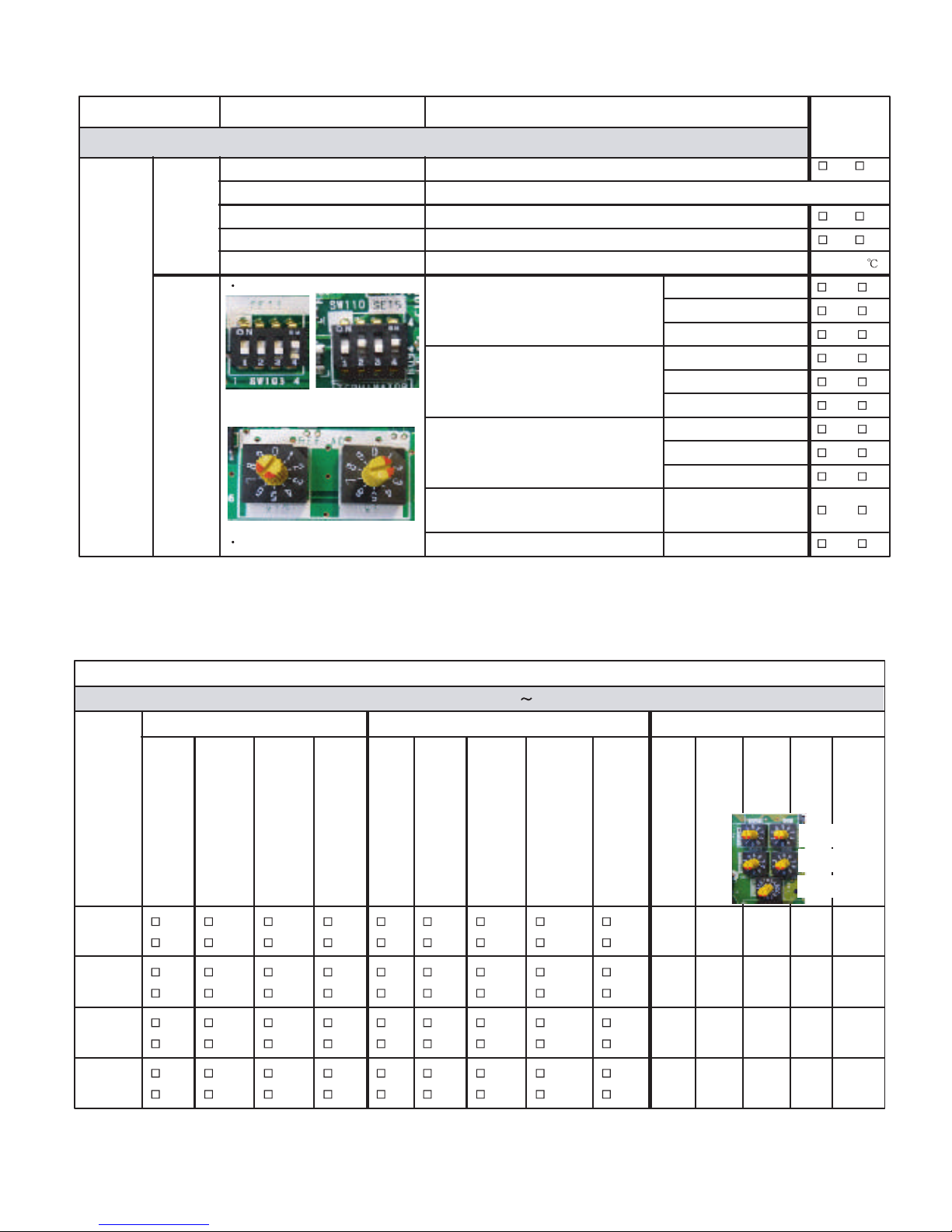
DIP-SW setting
OU Address (SET 3-1 & SET 3 -2)
Note:setting for Master & Slave units
(Default : OFF - OFF)
Master (OFF - OFF)
Y / N
Slave-1 (OFF - ON)
Y / N
Slave-2 (ON - OFF)
Y / N
No. of Slave Unit (SET 3- 3 & SET 3 -4)
Note:setting for Master unit only
(Default : OFF- OFF)
NO Slave (OFF- OFF)
Y / N
1 x Slave (OFF- ON)
Y / N
2 x Slave (ON - OFF)
Y / N
No. of OU (SET 5 -1 & SET 5 -2)
Note:setting for Master & Slave units
(Default : OFF-OFF)
1 x OU (OFF - OFF)
Y / N
2 x OU (OFF - ON)
Y / N
3 x OU (ON - OFF)
Y / N
Terminal Register (SET 5 - 4)
Note : setting for Master units
OFF or ON
(Default : OFF)
Y / N
Rotary-SW setting
Ref. Add. (among Master & Slave units) Ref ADx10 & Ref ADx1
Y / N
SET-5
SET-3
x 10 x 1
REF- AD
Check contents
Ref. circuit name: _________________, Ref. address: ____ (00
99)
Model
Name &
Serial
No.
Outlook Function setting by DIP-SW (Off / On) Add. Setting (by Rotary-SW)
Access hole for maintenance
(For Duct type & Cassette
type units)
RC wiring connection points:
(loose / deform)
Refrigerant pipes insulation
Drain pipes installation
Wired RC setting (DIP SW
1
)
2
wire /
3
wire
(default:
2
wire)
External Input (edge/pulse)
SET
2
2
( default: OFF )
Wireless RC custom code
SW
1
SET
3
1
( default: OFF )
Wireless RC custom code
SW
2
SET
3
2
( default: OFF )
Drain Pump SW (for Slim duct)
SET
4
1
( default: OFF )
Ref. Add.
(REF AD x
10
)
Ref. Add.
(REF AD x
1
)
IU Add.
(IU AD x
10
)
IU Add.
(IU AD x
1
)
RC Add.
(RC AD)
Y /
N
Y /
N
Y /
N
Y /
N
Y / NY /
N
Y /
N
Y /
N
Y /
N
Y /
N
Y /
N
Y /
N
Y /
N
Y / NY /
N
Y /
N
Y /
N
Y /
N
Y /
N
Y /
N
Y /
N
Y /
N
Y / NY /
N
Y /
N
Y /
N
Y /
N
Y /
N
Y /
N
Y /
N
Y /
N
Y / NY /
N
Y /
N
Y /
N
Y /
N
IU Add.
Ref. Add.
RC Add
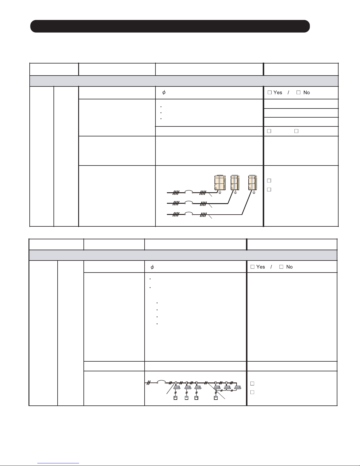
1-2-2 Outdoor unit field setting inspection sheet
1-2-3 Indoor unit field setting inspection sheet
Page 10
01-05
Check Item Check contents Judgement Present Status
Number of ref. circuit connected in the network system: ______, Ref. addresses: ______________(00 - 99)
VRF
Network
System
Transmission wire
Outlook
Is it LonWorks compatible?
Yes / No
Maker name?
Wire specification 0.33mm
2
, shield wire
(mm2)
Transmission line
connection points
Between Master OUs
Must be properly connected (Between Master OUs)
Master OUs
Terminal: Z1 & Z2
Yes / No
Between Master OU &
Slave OU or
In between Salve OUs
Must be properly connected (Between Master OU and
Slave OU / Slave OU and Slave OU )
Terminal: H1 & H2
Yes / No
Shield wire connection
Both ends of shield wire must be grounded
Yes / No
Wiring connection Wiring connection per terminal (
2)
Yes / No
1-2-4 Transmission wire installation inspection sheet 1/3
1-2-4 Transmission wire installation inspection sheet 2/3
Indoor unit
Outdoor unit (Master unit)
Refrigerant system
Check Item Check contents Judgement Present Status
Number of ref. circuit connected in the network system: ______, Ref. addresses:_______________(00 99)
VRF Network
System
Network
wiring
Total transmission line length
Wiring length
3600m
(Value ta ken from Network Design Drawing)
(m)
Network wiring layout
Do not make a loop configuration Looped / Not looped
No. of network segment
( * 1)
No. of network segment 41
( * 1)
Create one Network Segment based on the following conditions,
Condition -1: if the transmission line length 500m
Condition -2: if a total number of connected units
64 connected units
( * 2)
( *2) connected units mean a total of ( Indoor Units + Master Outd oor Units
+ TPC Units + System Controller Units
+ Network Convertor f o r LonWorks Unit + Central RC Units + Network Convertor Units
+ BACnet Gateway Unit + Signal Amplif ier Units + Service Tool Unit + Web Monitoring To ol Unit)
Page 11
01-06
Check Item Check contents Judgement Present Status
Number of ref. circuit connected in the network system : ______, Ref. addresses :_______ _______________(00
99)
VRF
Network
System
Network
Conf iguration
No. of IUs & OUs
For one VRF Network System
(IU
400 & OU 100)
IU number : _____
OU num ber: _____
No. of System Controller
One System Controller per VRF Network System
No. of Touch panel controller (TPC)
Connectable No s. 16
Total 16 Nos.
Per VRF Network System
(including one Network
Converter for LonWorks)
TPC: _____
No. of Central RC (CRC)
Connectable No s. 16
CRC: ______
No. of Network Convert f or Group RC
Connectable No s. 64
Group RC: _____
No. of Signal Amplifier (SA) 40
Detail contents:
No. of SA (filter mode OFF) 8
No. of SA (filter mode ON ) 32
One per 500m transm ission lin e length OR,
One per 400m transm ission line length between
units OR,
One per every 64 nu mber of connected units OR,
One per every ma ster OU if tota l n um ber of
connected Indoor Units
320
Number of Signal
Amplifier :____ ____
No. of Network Convertor ( 100)
One for each separa te Room Air- conditioning system Tota l:_______
No. of BACnet Gateway
One BACnet Gateway per VRF Network System Tota l: _______
Terminal Register
One per Network Segment (refer to table -9) Tota l: _______
No. of Network Convertor for LonWorks
One per VRF Network System (IU 128 & OU 100)
NOTE: Special VRF Network system con figuration
IU number : _____
OU num ber: _____
Check Item Check contents Judgement Present Status
Number of ref. circuit connected in the network system : ______, Ref. addresses :_______________________(00
99)
VRF
Network
System
Terminal
Resistance of
transmission
line
Terminal resistance of transmission line:
From device with connected terminal
resistance (OU or SA) to the most
distance device
50 ohm ( Resistance value) 180 ohm
OK / Not OK
In- between
OU (add____) & SA (add___)
OK / Not OK
In- between
SA (add____)
OK / Not OK
In- between
OU (add____) & SA (add___)
1-2-4 Transmission wire installation inspection sheet 3/3
Distance from termination resistor (m)
0 ~100 ~ 200 ~ 300 ~400 ~500
Approximate resistance (Ω)
0 ~ 50
A short circuit somewhere or 2 or more termination
resistors are connected
50
60
70
80
90
100
110
120
130
140
150
160
170
180
190 ~ Faulty contact or wiring length over 500 m
1K ~∞ Faulty contact, open circuit, or no termination resistor
Page 12
01-07
Check Item Check contents Judgement Present Status
Ref. circuit name : _________________________________, Ref. address: ______________ (00
99)
Refrigerant
system
piping
Outlook
Insulation & Fastening Insulated without gap & properly fastened (Yes / No)
Yes / No
Suction line filter Is there any external filter in the suction line
Yes / No
Oil Trap If Distance between OUs 2m ,
Place oil trap both at suction & at Discharge line
Yes / No
Not applicable
Piping
Actual Pipe Length
Actual Pipe Length
Actual Pipe Length
1 outdoor unit connected2 outdoor units connected3 outdoor units connected
Between Master OU and farthest IU
(
165m)
Between Master OU and farthest IU
( 165m)
Between Master OU and farthest IU
(
165m)
(
700m )
(m)
Between first separation tube and farthest IU
(farthest IU) - (closest IU)
(
60m )
(farthest IU) - (closest IU)
(
60m )
(farthest IU) - (closest IU)
( 60m )
(
90m )
Between first separation tube and farthest IU
(
90m )
Between farthest OU and first OU branch kit
(
12m )
Between first separation tube and farthest IU
(
90m )
Between OU and OU branch kit
( 3m )
Between OU and OU branch kit
(
3m )
(m)
Total Pipe Length
(
1000m)
Total Pipe Length
(
1000m)
Total Pipe Length
(m)
(m)
(m)
(m)
(m)
(m)
(m)
(m)
(m)
(m)
(m)
(m)
(m)
(m)
(m)
(m)
(m)
(m)
(m)
(m)
(m)
(m)
Height Difference
Height Difference
Height Difference
Between OU and IU (when OU is installed above)
( 50m)
Between OU and IU (when OU is installed above)
( 50m)
Between OU and IU (when OU is installed above)
( 50m)
(
40m)
(
15m)
(m)
Between OU and IU (when OU is installed below)
( 40m)
Between OU and IU (when OU is installed below)
( 40m)
Between OU and IU (when OU is installed below)
(m)Between IUs
(
15m)
Between IUs
(
15m)
Between IUs
(
0.5m )
Between OUs
(
0.5m )
Between OUs
1-2-5 Piping installation inspection sheet
Page 13
01-08
Check Item Check contents Judgement Present Status
Ref. circuit name: ____________________________, Ref. address :________(00
99)
Additional
Charged
Refrigerant
Outdoor Unit
OU Model Name Additional Refrigerant Amount for OU
AJ* 072L / AJ* 090L / AJ* 108L
AJ* 126L / AJ* 144L / AJ* 162L
AJ* 072L / AJ* 090L : 0 (kg)
AJ* 108L / AJ* 126L / AJ* 144L / AJ* 162L : 3.3 (kg)
(kg)
Connecting
Pipe
Liquid Pipe Length Additional Refrigerant Amount based on the liquid pipe length
@ 6.35mm (m)
For pipe diam eter 6.35m m : 0.021 kg/m
For pipe diam eter 9.52m m : 0.058 kg/m
For pipe diam eter 12.7mm : 0.114 kg/m
For pipe diam eter 15.88mm : 0.178 kg/m
For pipe diam eter 19.0
5mm : 0.268 kg/m
(kg)
@ 9.52mm (m)
(kg)
@ 12 .7mm (m)
(kg)
@ 15 .88m m (m )
(kg)
@ 19 .05m m (m )
(kg)
Total Additional Amount of Charged Refrigerant
(kg)
Note: In the refrigerant system, overall refrigerant amount
31.5 kg (for 1 OU), 63.0 kg (for 2 OUs) and 94.5 kg (for 3 OUs)
Overall refrigerant amount (kg) in the refrigerant system = Factory charged refrigerant (kg) for OU
+ Total additional amount of
charged refrigerant (kg) [= Additional charged refrigerant for OU +
Additional charged refrigerant for connecting pipe]
Factory charged refrigerant f or outdoor unit :
AJ* 072L or AJ* 090L : 11.7 (kg)
AJ* 108L or AJ* 126L or AJ* 144L or AJ* 162L : 11.8(kg)
Check Item Check contents Judgement Present Status
Ref. circuit name: ____________________________, Ref. address :________(00
99)
Outdoor Unit
3-way
valves
opening
3-way valve of each OU at
- Discharge pipe side
- Suction pipe side
- Liquid pipe side
Master OU ( all 3 -way valve must be full open )
Yes / No
Slave-1 OU ( all 3-way valve must be full open )
Yes / No
Slave-2 OU ( all 3-way valve must be full open )
Yes / No
1-2-6 Refrigerant charge amount inspection sheet
1-2-7 3-way valve opening inspection sheet
Page 14
01-09
Check Item Check contents Judgement Present Status
Ref. circuit name _______________________, Ref. address ________(00
99)
Power
Source
Outdoor Unit
Actual Power Supply (V)
Between R-S / S-T / T-R
< 3, 4Wire + ground, 50Hz >
AC (380 - 415V)
10%
Incom ing volta ge per brea ker
Master (V): R-S:_____ / S -T:____ / T-R:____
Slave -1 (V): R-S:_____ / S -T:____ / T-R:____
Slave -2 (V): R-S:_____ / S -T:____ / T-R:____
Indoor Unit
Actual Power Supply (V)
< 1, 2Wire + ground, 50Hz >
Incom ing volta ge per brea ker
Breaker-1 (V): _______
Breaker -2 (V): _______
Breaker -3 (V): _______
_______
Check Contents Judgement Present Status
Ref. circuit name ________________________, Ref. address ________(00
99)
For each
refrigerant
system
Outdoor unit Check PCB- Lighting status
Ma ster
LED101 (g reen light)
Judgment : must be ON
Yes / No
Note : LED102 (Red) mu st not be flash & must not be ON
7-SEG LED
Judgment : ‘Sn’ displayed
Yes / No
LED101: Yes No
7-SEG :
Yes No
Slave -1
LED101: Yes No
7-SEG :
Yes No
Slave -2
LED101: Yes No
7-SEG :
Yes No
Indoor unit Check LED & RC display status
IU address _______
IU address _______
IU address ____ ___
IU address ____ ___
IU address _______
IU address _______
IU address _______
IU address ____ ___
IU address ____ ___
IU address _______
IU address _______
Indoor Unit
For Wall mounted, Universal, Celling & Small Cassette
Check IU opera tion LED & timer LED condition
Judgment : must be fla shing a lterna te ly
Yes / No
For Large Cassette a nd Duct type IU
Check Wired RC (3- wire) display screen
Judgment : Clock display “AM 12:00” will appear
Yes / No
Check Wired RC (2-wire) display screen
Judgment : La ngua ge selection screen will ap pea r
Yes / No
Yes No
Yes No
Yes No
Yes No
Yes No
Yes No
Yes No
Yes No
Yes No
Yes No
Yes No
Yes No
AC (220 - 240V) 10%
Overview of system operation check procedure
Step-1: Connect Service Tool PC to the VRF V-III system.
Do scaning of refrigerant system which should be commissioned.
Step-2: Compare the number of installed units (OU and IU) with the System List data obtained from the Service Tool.
Step-3: Operate all Indoor Units under Test Mode Cooling (Select Test mode either cool or heat based on ambient temperature.).
Step-3-1: During operation, check the IU thermistor value
Step-3-2: After 1-hour operation, check the Refrigerant System
Step-4: After 1-hour Test run operation (excluding special operation),
Step-4-1: Switching the operation mode of IU from cool to heat.
- Check the IU thermistor value
Step-4-2: When all IUs run under heating, continue operation minimum 15min. And check the Refrigerant system
1-3-2 Error indication check sheet
1-3 Check Items After Power ON
1-3-1 Power source check sheet
Page 15
01-10
Check Contents Check items Checking method Judgement Present Status
Ref. circuit : Name ____ _____ _____ ___, Ref. address ________(select f rom 00 to 99) Design value Check status
Installed units
and
their addresses
check
Number of IU
IU address
Checked by
Service Tool
Number of units and their
address appeared in the
System List must be same
as the Actual Design value
Judgment:
(OK / Not OK)
Connected number of IU ______
IU add _____
IU add _____
IU add _____
IU add _____
IU add _____
IU add _____
IU add _____
IU add _____
IU add _____
IU add _____
IU add _____
IU add _____
IU add _____
IU add _____
IU add _____
OK
Not OK
1-3-3 Installed unit and their addresses check sheet
Page 16

01-11
Check Contents Check items Checking method Judgement Present Status
Ref. circuit : Name ____ _____ _____ ___, Ref. address ________(select f rom 00 to 99)
Design val ue
Check status
Transmission line
connection
confirmation
check
Cooling status Operate all Indoor
Units under Test-run
Cooling Mode by
using Commissioning
Function of Service
Tool
Judgment Point during
test-mode cooling :
For Indoor Unit
-Thermistor value
(TH21 - TH22) 8
(Yes / No)
IU add _____ Yes / No
IU add _____
Yes / No
IU add _____
Yes / No
IU add _____
Yes / No
IU add _____
Yes / No
IU add _____
Yes / No
IU add _____
Yes / No
IU add _____ Yes / No
IU add _____
Yes / No
IU add _____
Yes / No
IU add _____
Yes / No
IU add _____
Yes / No
IU add _____
Yes / No
IU add _____
Yes / No
IU add _____
Yes / No
Yes / No
Yes / No
Yes / No
Yes / No
Yes / No
Yes / No
Yes / No
Yes / No
Yes / No
Yes / No
Yes / No
Yes / No
Yes / No
Yes / No
Yes / No
Check Contents Check items Checking method Judgement Present Status
Ref. circuit : Name ____ _____ _____ ___, Ref. address ________(select f rom 00 to 99)
Design val ue
Check status
Transmission line
connection
confirmation
Heating status
Switching the opera tion of IU
from cool to heat,
Control function of Service To ol
Judgment Point after
switching IU mode from
cool to heat :
For Indoor Unit
- Thermistor value
(TH24 > TH2 1)
(Yes / No)
IU
IU
IU add _____
IU add _____
IU add _____
IU add _____
IU add _____
IU add _____
IU add _____
IU add _____
IU add _____
IU add _____
IU add _____
IU add _____
IU add _____
IU add _____
IU add _____
1-3-4 Transmission line connection check sheet
Note: The following check method by using test-run is necessary for checking of incorrect transmission wire connection.
Page 17
01-12
Check Contents Judgement Present Status
Refrigerant Circuit : Name _________________, Address ________(00
99)
Conducted by
Service Tool
Degree of sub-cool at OU sub - cooler side should be,
5
Tsc 20 AND
Pulse value EEV3 should be,
Yes / No
Discharge refrigerant pressure should be,
2.5MPa Pd 3.3MPa
Yes / No
Suction refrigerant pressure should be,
0.7MPa Ps 1.2MPa
Yes / No
Discharge refrigerant temp. should be,
Discharge refrigerant superheat should be,
Yes / No
IU refg. superheat should be, 2
Pulse value IU EEV should be, EEV 1000P
Yes / No
Ps between Master & Slave OUs should be,
Ps 0.2 MPa
Yes / No
Air temperature of each IU should be,
Tair c ooling
>
8
Yes / No
No water fall from IU
No abnormal noise from IU
Yes / No
EEV3 400P
Td 100
AND
Tshd > 10
Tshe 20 AND
Tsc
EEV3 P
Pd MPa
Ps MPa
Td
Tshd
Tshe
IU EEV P
Ps MPa
Tair c ooling
Tsc = Saturated liquid temperature of HPS - TH5
Tshd = TH1- Saturated liquid temperature of HPS
Tshe = TH24 - TH22
Tair c ooling = TH21 - Outlet Air temperature
Td = TH1
Pd = HPS
Ps = LPS
Reference mark of Service tool
Check Contents Judgement Present Status
Refrigerant Circuit : Name _________________, Address ________(00
99)
Test-run operation
Heating mode
Conducted by
Service Tool
Discharge refrigerant pressure should be,
Suction refrigerant pressure should be,
Discharge refrigerant temperature should be,
Discharge refrigerant superheat should be,
Degree of sub cool (at IU side) should be,
Refrigerant superheat (at OU side) should be,
Pd between Master & S lave OUs should be,
T
OUHE
at each OU connected in series should be,
Air temperature of each IU should be,
2.5MPa Pd 3.3MPa
0.3MPa Ps 1.2MPa
Td 100
AND
Tshd > 10
Tsc 7
AND
4
Tshe1 & Tshe2 5
2
T
> 5
OUHE*
Ps 0.2 MPa
Tair heating > 15
Tsc = Saturated liquid temperature of HPS - TH22
Tshd = TH1- Saturated liquid temperature of HPS
Tshe1 = TH7 - Saturated vapor temperature of LPS
Tair heating = TH21 - Outlet Air temperature
Reference mark of Service tool
Yes / No
Yes / No
Yes / No
Yes / No
Yes / No
Yes / No
Yes / No
Tsc
Pd MPa
Ps MPa
Td
Tshd
Tshe
Ps MPa
Tair heating
TOUHE
Tshe2 = TH8 - Saturated vapor temperature of LPS
T = TH4 - TH9
OUHE 1
T = TH4 - TH10
OUHE 2
Test-run operation
Cooling mode
1-3-5 Operation check sheet
Page 18
01-13
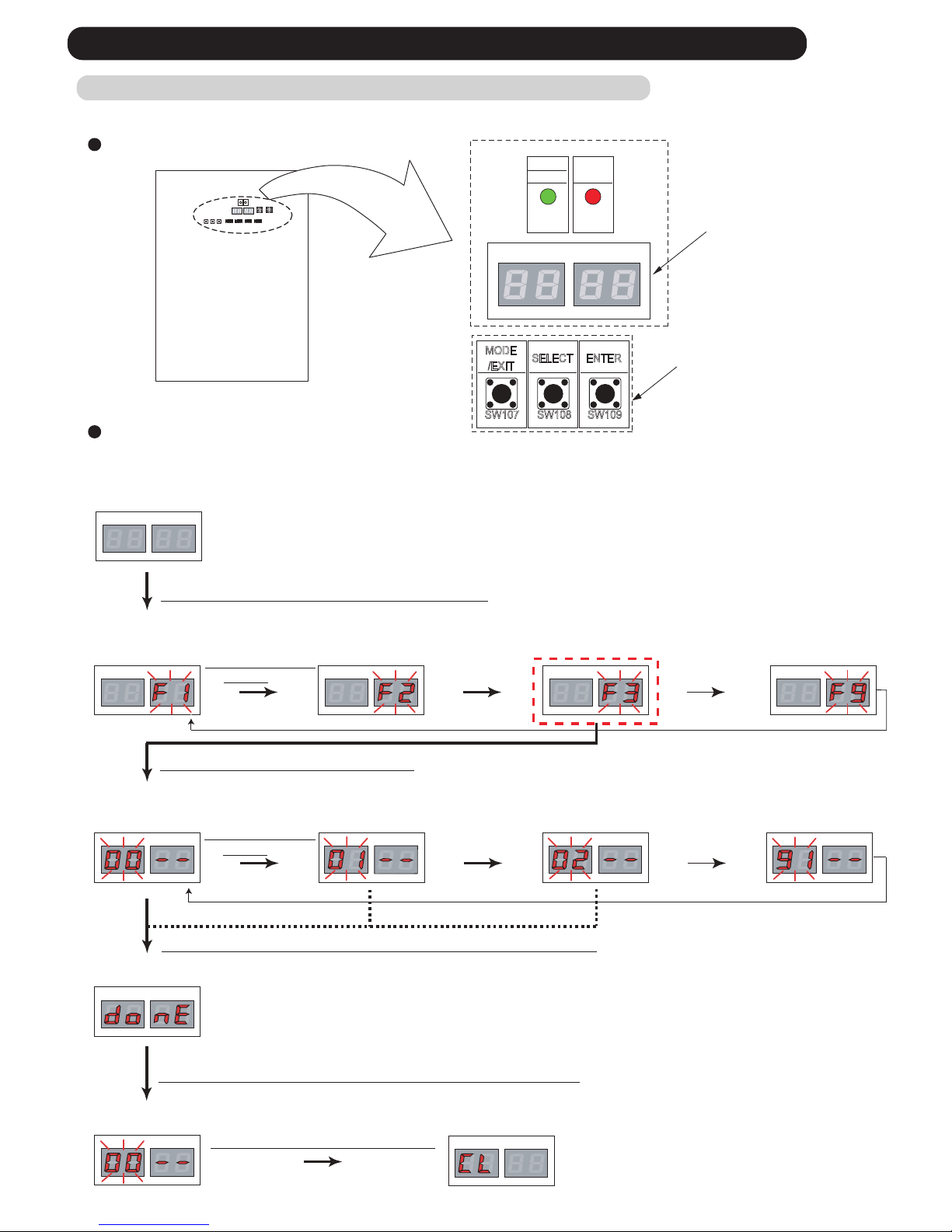
All the indoor units connected to the outdoor unit can be test-operated by push button setting. (Only for master unit)
LED105 LED104LED105 LED104 LED105 LED104LED105 LED104
LED105
LED104
LED105 LED104
LED105 LED104
[ Cooling test run ]
[ Heating test run ]
[ Test run stop ]
LED105 LED104
LED105 LED104
LED105 LED104
LED105 LED104
(3) Press the ENTER button ( SW109 )
(5) Hold down the ENTER button ( SW109 ) for at least 3 seconds.
(6) Press the ENTER button ( SW109 ) or Time out ( 5 seconds)
(1) Press the MODE / EXIT button ( SW107 ) once.
< Pursuance completion >
< Monitoring condition >
< Mode select condition >
< Return to mode select condition >
< Fuction select condition >
[ Function mode ]
SWITCH POSITION
SW107 SW108 SW109
MODE
/EXIT
SELECT ENTER
LED101
(GREEN)
POWER
MODE
LED105 LED104
LED102
(RED)
ERROR
Push button switch
7 Segment
LED Lamp
Outdoor unit printed circuit board
TEST RUN SETTING
(2)Press SELECT
button
[ Monitoring mode ] [ Setting mode ] [ Error history mode ]
For a detailed description of push button operation, refer to the [D&T manual Chapter 6. SYSTEM DESIGN]
(4)Press SELECT
button
LED105 LED104
< Return to monitoring condition >
(7) Press the MODE / EXIT button
example,
Normal indicate : [ Cooling mode ]
[ Central control setting
Forced reset ]
1-4 Test Run Operation
1-4-1 Test Run From Outdoor unit PC Board
Page 19

1-4-2 Test Run From Remote Controller
Short two metal contacts under the battery compartment lid, while the air conditioner is running.
To stop test run operation, push button of the wireless
remote controller.
When the air conditioner is being test run, the OPERATION
and TIMER lamps of indoor unit flash slowly at the same time.
START/STOP button
Test run button
2. Standard wireless remote controller
Stop the indoor unit. Push the button and
button simultaneously for more than two seconds.
The air conditioner will start to conduct a test run and " " will display on
the remote controller display.
However, the , setting button does not have function,
but all other buttons, displays, and protection functions will operate.
To stop test run, push the START / STOP button of the standard wired remote
controller.
For the operation method, refer to the operating manual and perform operation
check.
Check that there are no abnormal sounds or vibration sounds during test run
operation.
Perform the test operation for 60 minutes.
1. Standard wired remote controller
UTY - LNH
UTY - RNK
button
button and
Stop the indoor and outdoor units. Push the remote controller
simultaneously for more than three seconds. The air conditioner will start to conduct a test
run and " " will display on the temperature display.
SET
However the setting button does not have function but all other buttons,
displays and protection functions will operate.
To stop test running press the button of the simple remote controller.
For the operation method refer to the operating manual and perform operation check.
Check that there are no abnormal sounds or vibration sounds during test run operation.
3. Simple remote controller
UTY - RSK
01-14
TIMER MODE
CLOCK
ADJUST
TEST
RUN
RESET
TIMER
SLEEP
FILTER RESET
SWING
SET
SET
ECONOMY
FANMODE
ON
OFF
SET
TEMP.
TIMER MODE DAY
SET BACK
CLOCK ADJUST
DAY OFF
TIMER DELETE TIMER SET
FAN MODE
SET TEMP.
START / STOP
Page 20
01-15
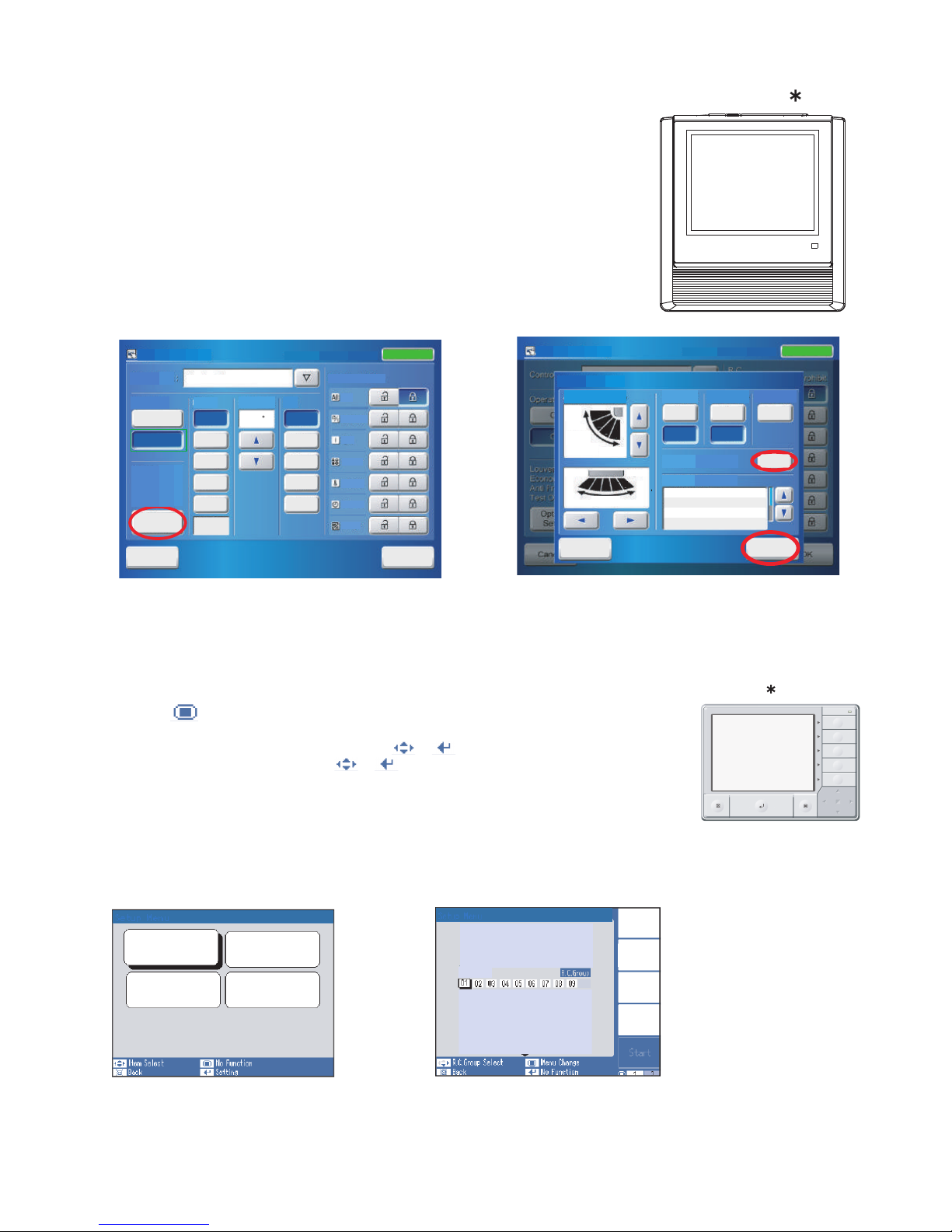
UTY - DTG
(1) Select the objective you want to test run.
Select the objective icon or list at the monitor screen. (Multiple selections is possible)
Select all the devices registered as objectives by pressing "Select All" on the monitor screen.
(2) After objective selection at (1), switch to the <Setting screen> by pressing "Operation".
(3) Switch to the <Detail setting screen > by pressing "Optional setting" on the setting screen,
(4) Press "Start" button and OK on the details setting screen.
Test run continues for 60 minutes.
To interrupt test run, select the device being the test run and excute an operation stop.
At the monitor screen, test run can cancel by selecting objective device and press OFF.
4. Touch panel controller
On
On
Reset
Cancel
Stand by (Defrost)
Stand by (Oil Recovery)
Test Operation
Start
Air Flow Direction
Economy
Anti Freeze
Filter Sign
Operation
Test
Up
Down
Swing
Swing
Left Right
Off
Off
Special State
1
2
3
4
5
1
2
3
4
SettingOptional
10/11.2008.Mar. 02:20 PM
Operation Setting
OK
Status: On
<Setting screen>
Cancel
Off
On
OK
Status: On
Cancel
OK
On
Off
Auto
Auto
Cool
Dry
Fan
Heat
Operation
Controlled
High
Med
Low
Quiet
Meeting Room
24.0 C
operation
R/C Prohibition
Mode Set Temp. Fan
Optional
Setting
All
On/Off
Filter
Timer
Temp.
Mode
On
10/11.2008.Mar. 02:20 PM
Air Flow Direction
Economy
Anti Freeze
Filter Sign
Test Operation
Control Unit :
Operation Setting
<Detail Setting screen>
[ Select All ]: All of R.C.Group (Indoor units)
[ Identify Unit ] : Specific R.C.Group (Indoor unit)
Indoor unit Special Setting
Test Operation
Indoor Unit
Set Temp. Range
Filter Sign
R.C. Prohibition
Group
Select
All
Identify
Unit
Clear
Unit
UTY-DCG
05/31 03:59
Test Operation
05/31 03:59
RCG_05
(1) Press " " button.
(2) Press "Set up Menue" and input password.
(3) Select "Indoor unit special setting" by presing or button.
(4) Select "Test operation by presing" or button
(5) Press the "Select ALL button" or "ldentify unit" button
(6) Press the " Start " button
The test run continues for 60 minutes.
To interrupt test run before it is complet, return to the "Monitor Mode Screen",
and press ON/ OFF.
5. Central remote controller
Page 21
(1) Press "Menu" on the monitor screen. the < Main Menu screen > is displayed.
(2) Press "Next Page" and press "Maintenance"
(3) Press "Next Page" and press "Test Run". the <Test run screen > is displayed.
(4) Press "OK"
The test run continues for 60 minutes.
To interrupt test run before it is complet, return to the "Monitor Mode Screen",
and press ON/ OFF.
6. 2-wire type wired remote controller
< Monitor Mode Screen >
< Main Manu Screen >
< Maintenance Screen >
UTY - RNR
< Test Run Screen >
01-16
Page 22
1-5 TEST RUN CONTROL
01-17
1. When the test run signal is transmitted from standard wired, wireless remote controller,
simple remote controller, transmitted netwwork, and outdoor unit.
(1) The test run operation starts and the electric expansion valve is controlled to a maximum flow, regardless of
the temperature condition.
(2) Frost prevention operation has priority over item(1).
(3) Whether state of the indoor unit operates or stops, All units in the same refrigerant circuit will start to conduct a
test run in accordance with the operation mode set by push switch of outdoor unit ( see 1 - 2 - 3 ).
(4) After 60 minutes passes, the test run stops.
(5) Test running initialization is shown below.
* The temperature controlling on the test run operates regardless of setting temperature.
Fan speed Hi Hi Hi Hi
Vertical Air Direction Panel
Swing
Operating Mode
Cooling Heating Cooling Heating
OFF OFF
Position
1
Position
4
EXCEPT FOR THE DUCT MODEL DUCT TYPE
COMPACT CASSETTE TYPE
COMPACT WALL MOUNTED TYPE
1
2
3
4
*EXAMPLE
1
2
3
4
4
3
2
1
CEILING TYPE
4
3
2
1
Page 23
Push switch on
outdoor unit PCB
00 Connected number of indoor unit The number of the communicating unit is displayed
01
Software version :
[ ] [ ] [ ] [ ] [ ] displays by five items
It skips when there is no suffix
02 Software version of INV PCB
03
Software version of communication PCB
Operation of
each part
10 Rotational speed of outdoor unit
fan motor
The rotational speed of the outdoor unit fan motor is displayed
[ 0 ~ 999 ] rpm
11 Rotational speed of INV
compressor
The rotational speed of the compressor is displayed
[ 0 ~ 999 ] rps
12 Current value of INV compressor Current value of INV compressor is displayed
[ 0.00 ~ 99.99 ] A
14 Pulse of EEV1 Pulse of EEV1 is displayed
[ 0 ~ 9999 ] pls
15 Pulse of EEV2 Pulse of EEV2 is displayed
[ 0 ~ 9999 ] pls
Time guard 20 Accumulated current time Accumulated current time is displayed
[ 0 ~ 9999 ]
10hour
21 INV compressor accumulated time
[ Cooling ]
Accumulated time is displayed in the cooling operation of the
INV compressor
[ 0 ~ 9999 ]
10hour
22 INV compressor accumulated time
[ Heating ]
Accumulated time is displayed in the heating operation of the
INV compressor
[ 0 ~ 9999 ]
10hour
Refrigerant
cycle data 1
30 Information on Thermistor 1 The value of the Thermistor 1 is displayed
[ -99.9 ~ 999.9 ]
C or F
31 Information on Thermistor 2 The value of the Thermistor 2 is displayed
[ -99.9 ~ 999.9 ]
32 Information on Thermistor 3 The value of the Thermistor 3 is displayed
[ -99.9 ~ 999.9 ]
33 Information on Thermistor 4 The value of the Thermistor 4 is displayed
[ -99.9 ~ 999.9 ]
34 Information on Thermistor 5 The value of the Thermistor 5 is displayed
[ -99.9 ~ 999.9 ]
35 Information on Thermistor 6 The value of the Thermistor 6 is displayed
[ -99.9 ~ 999.9 ]
36 Information on Thermistor 7 The value of the Thermistor 7 is displayed
[ -99.9 ~ 999.9 ]
37 Information on Thermistor 8 The value of the Thermistor 8 is displayed
[ -99.9 ~ 999.9 ]
38 Information on Thermistor 9 The value of the Thermistor 9 is displayed
[ -99.9 ~ 999.9 ]
39 Information on Thermistor 10 The value of the Thermistor 10 is displayed
[ -99.9 ~ 999.9 ]
40 Information on Thermistor 11 The value of the Thermistor 11 is displayed
[ -99.9 ~ 999.9 ]
50 Information on pressure sensor 1
( High pressure sensor )
The value of the pressure sensor 1 is displayed
Refrigerant
cycle data 3
If unit is [MPa], it is displayed as [ 0.00 ~ 9.99 ]
[psi], it is displayed as [ 0.0 ~ 999.9 ]
51 Information on pressure sensor 2
( Low pressure sensor )
The value of the pressure sensor 2 is displayed
If unit is [MPa], it is displayed as [0.00 ~ 9.99]
[psi], it is displayed as [ 0.0 ~ 999.9 ]
[ F1 ]
Monitor mode
Setting Mode
ITEM
CODE No.
Information contents
ITEM
CODE No.
Refrigerant
cycle data 2
C or F
C or F
C or F
C or F
C or F
C or F
C or F
C or F
C or F
C or F
Device and
system
Software version of outdoor unit
Classification
01-18
1-6 Field Setting And Monitor Mode List for Outdoor unit
( Discharge temperature sensor 1)
( Outdoor temperature sensor )
( Suction temperature sensor )
( Liquid temperature sensor 1)
(Liquid temperature sensor 2)
( Sub-cool H-Ex (outlet) sensor )
(Heat exchanger 1 gas sensor1)
(Heat exchanger 2 gas sensor2)
(Heat exchanger 1 liquid sensor)
(Heat exchanger 2 liquid sensor)
(Compressor temperature sensor)
16 Pulse of EEV3 Pulse of EEV3 is displayed
[ 0 ~ 9999 ] pls
Page 24
Install 00 Pipe length setting 00 40-65m
Setting mode
01 0-40m
02 65-90m
03 90-120m
04 120-165m
Correction 10 Sequential start shift 00
01 21sec. Delay
02 42sec. Delay
03 63sec. Delay
11
Cooling capacity shift 00 Normal mode
01 Save energy mode (+2 )
02 High power mode 1 (-2 C)
03 High power mode 2 (-4 C)
12
Heating capacity shift
00 Normal mode
01 Save energy mode (-2 C)
02 High power mode 1 (+2 C)
03 High power mode 2 (+4 C)
13,14,15 (Forbidden) 00
01
01 Emergency stop
21 Operation mode selecting method 00 Priority given to the first command
01 Priority given to the external input of outdoor unit
02 Priority given to the master indoor unit
22 Snow falling protection fan mode 00 Valid
01 Invalid
23 Interval setting for snow falling 00 Standard (30min)
01 Short 1 (5min)
02 Short 2 (10min)
03 Short 3 (20min)
24 High static pressure mode 00 Standard
01 High static pressure 1 (equivalent to 30Pa)
02 High static pressure 2 (equivalent to 82Pa)
25 00
01
Change of 30 Energy saving level setting 00 Level 1 (stop)
01 Level 2 (operated at 40% capacity)
02 Level 3 (operated at 60% capacity)
03 Level 4 (operated at 80% capacity)
Low noise 40 Capacity priority setting 00 Off (quiet priority)
01 On (capacity priority)
41 Low noise mode setting 00 Off (Normal)
01 On (Low noise mode operation is always done)
42 Low noise mode operation 00 Level 1 (55dB)
01 Level 2 (50dB)
[ F2 ]
Normal
20
*1 : If one of compressor fails, backup operation will be performed by the remaining compressors.( For starting the system SET4-2 switching is required)
*2 : If one of compressor fails, all units will be abnormal stop.
*3 : When electricity meter No. is set to "000" and "201 to 299", the pulses input to CN135 become ineffective.
Available setting number is "001" to "200"
*4 : When the electricity meter pulse setting is set to "0000", the pulses input to CN135 become ineffective.
Available setting number is "0001" to "9999"
00 Batch stop
Change of
function 1
Switching between batch stop or
emergency stop
protection fan mode
setting 1
(in low noise mode)
level setting
function 2
C
01-19
Push switch on
outdoor unit PCB
03
(Forbidden)
(Forbidden)
04 Level 5 (operated at 100% capacity)
26 00
01
27 00
01
28 00
01
29 00
01
(Forbidden)
(Forbidden)
(Forbidden)
(Forbidden)
(Forbidden)
70
Electricity meter No. setting 1
(Set the ones digit and tens digit of the No
of the electricity meter connected to CN135.)
00~99*3Setting number x00~x99 00
71
Electricity meter No. setting 2
(Set the hundreds digit of the No. of the
electricity meter connected to CN135.)
00~02*3Setting number 0xx~2xx 00
72
Electricity meter pulse setting 1
(Set the ones digit and tens digit of the No. of
the electricity meter pulse setting connected
to CN135.)
00~99*4Setting number xx00~xx99 00
73
Electricity meter pulse setting 2
(Set the hundreds digit and thousands digit
of the electricity meter pulse setting connected
to CN135.)
00~99*4Setting number 00xx~99xx 00
Change of
function 3
( Refer to Design & Technical Manual for details.)
( Refer to Design & Technical Manual for details.)
( Refer to Design & Technical Manual for details.)
( Refer to Design & Technical Manual for details.)
Setting Mode
ITEM
CODE No.
Setting Function
ITEM
CODE No.
Classification
Defalt
04
17
Height difference between
indoor units
00 Standard
Height difference
01
02
03
(Forbidden)
(Forbidden)
(Forbidden)
04
32 00
01
33 00
01
(Forbidden)
(Forbidden)
If installing the indoor units (even only one set) to a lower floor than the outdoor unit,
and the height difference between the indoor units is 3m or greater
(i.e., if installing the indoor units on separate floors), set “02 (height difference)”.
Page 25
Push switch on
outdoor unit PCB
Forced
operation
00 Cooling test run Forced thermostat-ON in Cooling
Function mode
01 Heating test run Forced thermostat-ON in Heating
02 Test run stop Test run is stopped
Install and
maintenance 1
10 Signal amplifier automatic address Automatic address setting operates for
signal amplifier
11 Indoor unit automatic address
21 Vacuuming mode Vacuuming mode operates
Refer to page 01-01 for the function
Clear 30 Error history clear All the abnormal code histories are cleared
32 Current time clear Accumulated current time becomes [ 0 ]
33 INV compressor accumulated time
clear
Accumulated time of the INV compressor
becomes [ 0 ]
35 Field setting all clear Return to default the all set items
Abnormal 40 Abnormal reset It was displayed when abnormality occurs,
and abnormal code is reset
This is a function that uses to clear abnormal display
after the repair is completed
Please operate the switch after power off or
power on the outdoor unit
Specialty
function
91 Foreced Central control function
forced release
When the centralized control device failure,
and the centralized control setting cannot
be released, this function is used
All the limitations set with the centralized control
device are released
Setting Mode
ITEM
CODE No.
Setting Function
Default
ITEM
CODE No.
Install and
maintenance 2
Automatic address setting operates for indoor
unit of same refrigerant circuit
[ F3 ]
01-20
*
<< Error code which manual error release will be required >>
A5.1Low pressure abnormal
84.1 Current sensor 1 error
93.1 Inverter compressor start up error
94.1 Trip detection
A1.1 Discharge temperature 1 abnormal
A3.1 Compressor 1 temperature abnormal
97.1 Outdoor unit fan motor lock error
97.5 Fan motor temperature abnormal
97.9 Fan motor driver abnormal
68.2 Rush current limiting resister temp rise protection
95.5 Compressor motor loss of synchronization
A6.3 Outdoor heat exchanger 1 gas temperature abnormal
A6.4 Outdoor heat exchanger 2 gas temperature abnormal
A4.1 High pressure Abnormal
86.4 High pressure SW 1 Error
Push switch on
outdoor unit PCB
1 time ago (Newest)
Error History Mode
2 times ago
5 times ago
Meaning of Error History Number
ITEM
CODE No.
Information contents
[ F9 ]
00
01
02
03
04
05
06
07
08
09
Error history
10 times ago (Oldest)
4 times ago
3 times ago
6 times ago
7 times ago
8 times ago
9 times ago
When the error occurred, the error code is memorized up to
10 on Main PCB.
If the memorized error code becomes over 10, the oldest one
will be erased.
Refer to Chapter TROUBLE SHOOTING
Error Code List of Outdoor unit
03,04
(Forbidden)
31
(Forbidden)
Page 26
01-21
1-7 Field Setting / Function Setting for Indoor unit
Setting Mode
ITEM
CODE No.
Setting Function
Default
Indoor unit field setting
setting by
remote controller
Address
01 Indoor unit address 00~63 00~63 00
02 Refrigerant circuit address 00~99 00~99 00
Filter 11 Filter indicator Interval 00 Default
01
Longer
02 Shorter
13 Filter sign display 00 Enable
01 Disable
02 Display only on central remote control
Airflow 20 Ceiling airflow 00 Default
(Cassette type only) 01 High ceiling
23 Vertical airflow direction 00 Default
01 Raise
24 Horizontal swing airflow direction 00 Default
01 Left half
02 Right half
Correction 30
Cool air temperature trigger
00 Default (0
°C
)
01 Temperature overshoot setting (+2
°C)
02 Temperature undershoot setting (-2
°C)
31 Heat air temperature trigger 00 Default (0°C)
01 Temperature undershoot setting (-6
°C)
02 Temperature slightly undershoot setting (-4
°C)
03 Temperature overshoot setting (+4
°C)
Change of 40 Auto restart *1 00 Enable
01 Disable
43 Cool air prevention 00 Super low
01 Follow the setting on the remote controller
46 External control 00 Start / Stop
01 Emergency stop
47 Error report target 00 All
01 Display only for central remote control
ITEM
CODE No.
Function 1
Classification
26
32
00
01
02
03
04
05
06
07
08
09
31
0 Pa
10 Pa
20 Pa
30 Pa
40 Pa
50 Pa
60 Pa
70 Pa
80 Pa
90 Pa
25 Pa (Standard)
Static Pressure setting
- Slim Duct Only -
The Range of static pressure is
different from one model to other.
Temperature correction in Auto
00
01
Disable
Enable (Nonfunctional on J2 Series)
02 Foreced stop (Start/Stop by RC is restricted)
49 FAN Setting when cooling thermo-
stat OFF *2
01
00
Follow the setting on the remote controller
Foreced stop
*1: Auto restart is an emargency function such as for power failure etc.
Do not start and stop the indoor unit by this function in normal operation.
Be sure to operate by the control unit, converter or external input device.
*2: Fan Setting when cooling thermostat OFF, Connection of the wired remote controller (2-wire type or 3-wire type) and switching its thermistor are necessary.
Model name Range of static pressure
ARXD04
ARXD18
ARXD07/09/12/14 0 to 90 Pa
ARXD24 0 to 50 Pa
Page 27
01-22
1-8 Field Setting / Function Setting for Outdoor air unit
Setting Mode
ITEM
CODE No.
Setting Function
Default
Indoor unit field setting
Address
setting by
remote controller
01 Indoor unit address 00~63 00~63 00
02 Refrigerant circuit address 00~99 00~99 00
Filter 11 Filter indicator Interval 00 Default
01
Longer
02 Shorter
13 Filter sign display 00 Enable
01 Disable
02 Display only on central remote control
Airflow
Change of
Function 1
40 Auto restart *1 00 Enable
01 Disable
43 Cool air prevention 00 Super low
01 Follow the setting on the remote controller
46 External control 00 Start / Stop
01 Emergency stop
47 Error report target
63 Humidifier control *2
00 All
01 Display only for central remote control
ITEM
CODE No.
Classification
26
05
06
07
08
09
10
11
12
13
14
15
16
17
18
19
20
21
22
31
SP mode 05
SP mode 06
SP mode 07
SP mode 08
SP mode 09
SP mode 10
SP mode 11
SP mode 12
SP mode 13
SP mode 14
SP mode 15
SP mode 16
SP mode 17
SP mode 18
SP mode 19
SP mode 20
SP mode 21
SP mode 22
Normal SP
Static Pressure setting
- Outdoor air unit Only -
The Range of static pressure is
different from one model to other.
02
Foreced stop (Start/Stop by RC is restricted)
00
01
02
mode 00
mode 01
mode 02
*1: Auto restart is an emargency function such as for power failure etc.
Do not start and stop the indoor unit by this function in normal operation.
Be sure to operate by the control unit, converter or external input device.
*2: Select control conditions of external output.
"Mode 00" is output when heating thermostat is ON, "Mode 01" is output in heating operation, "Mode 02" is output in heating operation and in fan operation.
Model name
ARXH054GTAH
ARQH140GTAH
ARXH072GTAH
ARQH224GTAH
ARXH096GTAH
ARQH280GTAH
Range of static
pressure
SP mode 05 to 19
(50 to 185 Pa)
SP mode 05 to 20
(50 to 200 Pa)
SP mode 05 to 22
(50 to 220 Pa)
Normal static
pressure
185 Pa
200 Pa
200 Pa
Page 28
2. OUTDOOR UNIT OPERATION CONTROL
Page 29
: Capillary
: Strainer
02-01
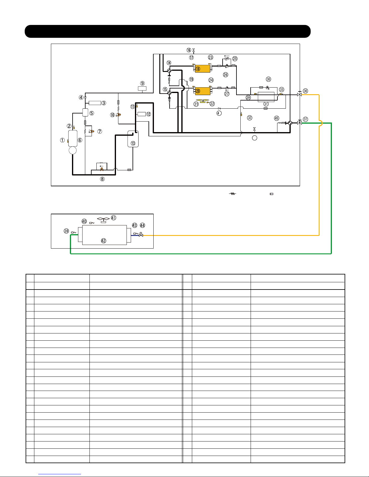
2-1 REFRIGERANT CIRCUIT
1 Compressor temp. Sensor 1 Detects the compressor temperature
No. Part name Function
2 Discharge temp. Sensor 1 Detects the discharge temperature
High pressure Swithch Detects abnormal high pressure (4.20 MPa)3
4 Check valve Comp. pressure equaization
Oil Separator Separates oil and refrigerant5
6 Compressor (Inverter) Operation range ( 20 rps - 90 rps )
7 Bypass / Oil return Valve HP-LP bypass in protection, Returns the oil to COMP
8 Oil return Valve Returns the oil to Compressor
9 High pressure Sensor Detects the High pressure
10 Bypass Valve
HP-LP bypass in protection / Comp. pressure equalization
11 Suction gas temp. Sensor
Collects refrigerant and the returned oil
12 Low pressure Sensor
Detects the temp of refrigerant
13 Acuumulator
Detects Low pressure
14 4-Way-Valve 1 Changes operation mode of HEX 1
Changes operation mode of HEX 24-Way-Valve 215
16 Service port Measure High pressure for Service
17 Heat-Ex 1 gas temp. Sensor Detects the temperature of refrigerant
Heat-Ex 2 gas temp. Sensor Detects the temperature of refrigerant
18 Heat Exchanger 1 Operates as Condenser / Evaporator
Heat Exchanger 2 Operates as Condenser / Evaporator
19
20
21 Outdoor unit FAN (Motor) Control FAN speed for heat exchange of HEX
22 Outdoor temp. Sensor Detects the ambient temperature
23 Heat-Ex 1 liquid temp. Sensor Detects the temperature of refrigerant
Heat-Ex 2 liquid temp. Sensor Detects the temperature of refrigerant24
25 Pressure regulation valve Operates in regulated pressure (4.00MPa)
26 Outdoor unit EEV1 Controls the flow of ref. based on target pressure
27 Outdoor unit EEV2 Controls the flow of ref. based on target pressure
29 Liquid pipe temp. Sensor 1 Detects the temperature of liquid refrigerant
Outdoor unit EEV3 Controls ref. subcooling /Operats in protection30
31 Sub-Cool Heat exchanger Subcool of liquid refrigerant
32
Sub-Cool HEX gas outlet temp
Sensor
Detects the temperature of refrigerant
33 Liquid pipe temp. Sensor 2 Detects the temperature of liquid refrigerant
36 3way-valve (Liquid) Open / Close for Liquid line
37 3way-valve (Gas) Open / Close for Gas line
38 Service port Measure Low pressure for Service
39 I.U HEX outlet temp. Sensor Detects the temperature of refrigerant
Detects the temperature of room
Room temp. Sensor40
41 Indoor unit FAN (Motor) Controlled by setting / protection / Thermo OFF
Changes operation mode
42 I.U Heat Exchanger Operates as Condensor / Evapolator
Indoor unit EEV Controlled by setting / protection / Thermo OFF
43 I.U HEX inlet temp. Sensor Detects the temperature of refrigerant
44
4-Way-Valve 345
Prevents the liquid refrigerant return at cooling
Check valve46
Function
Part name
No.
2. OUTDOOR UNIT
EEV21
LIQUID LINE
FAN21
Indoor unit1
Outdoor unit
HEX21
GAS LINE
TH21
TH22
TH24
SCHEX
CMP
(INV)
ACM
LPS
HEX1
TH11
TH1
HPSW1
SV2
SV3
TH3
TH2
EEV2
EEV1
TH4
EEV3
TH6
TH5
TH7
TH8
TH9
TH10
4WV 1
CMP
ACM
OS
HPS
FAN1
4WV 3
4WV 2
HEX2
SV1
6
38
Page 30
EEV21
FAN21
Outdoor air unit
(ARXH054/ 096GTAH)
HEX21
TH21
TH25
TH22
TH24
: Capillary
: Strainer
02-02
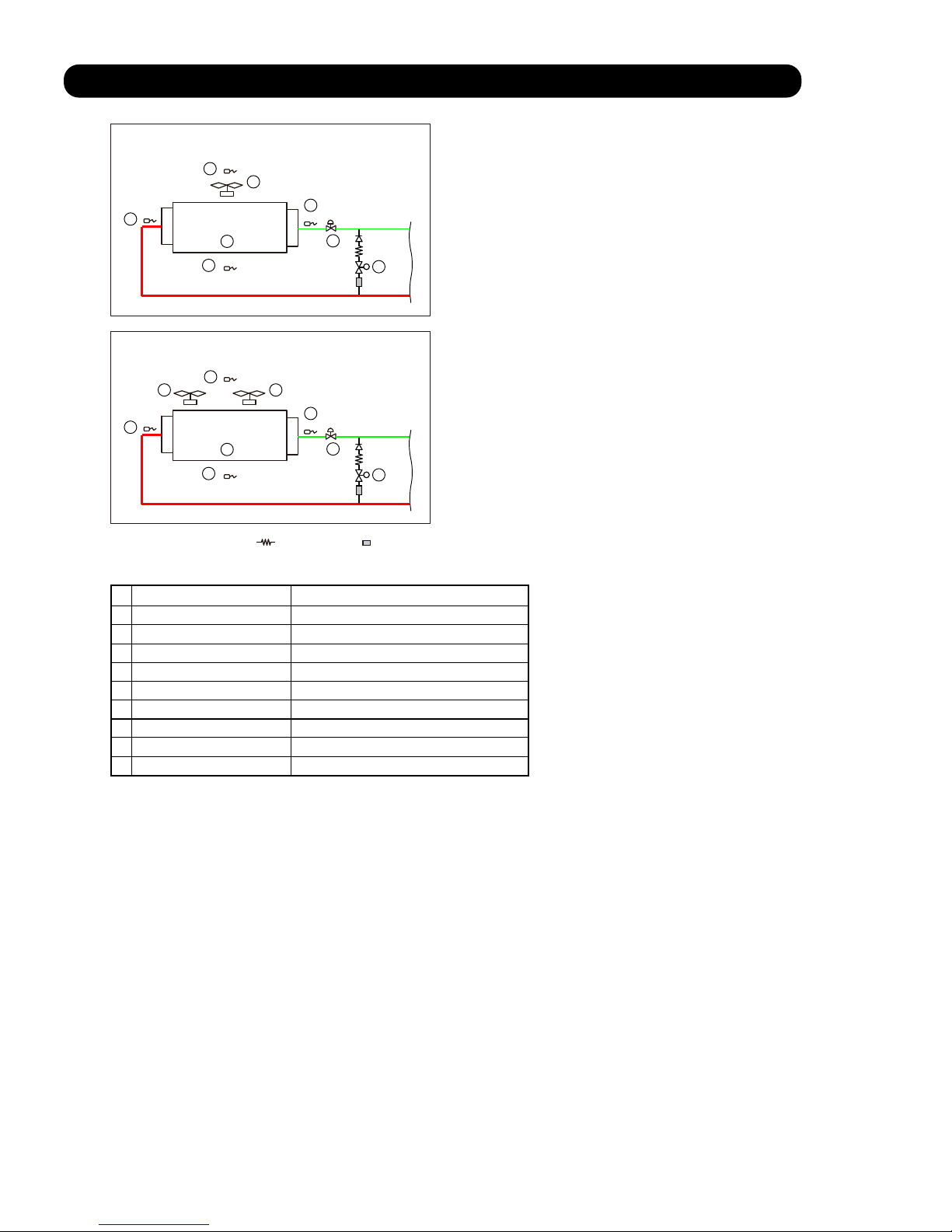
2-1-1 REFRIGERANT CIRCUIT for Outdoor air unit
51
No. Part name Function
52
53
54
55
56
57
58
59
Heat exchanger outlet thermistor Detects the temperature of refrigerant
Detects the temperature of suction airflow
Suction airflow temp. thermistor
Detects the temperature of discharge airflow
Discharge airflow temp. thermistor
Heat exchanger Operates as Condensor / Evapolator
Fan motor Controlled by setting / protection / Thermo OFF
Heat exchanger inlet thermistor Detects the temperature of refrigerant
Fan motor Controlled by setting / protection / Thermo OFF
Electric expansion valve Controlled by setting / protection / Thermo OFF
Solenoid valve (Bypass) Opens at Thermo OFF in Heating mode
51
52
59
53
56
54
57
58
EEV21
FAN22
Outdoor air unit
(ARXH072GTAH)
HEX21
TH21
TH25
TH22
TH24
51
52
59
53
56
54
FAN21
55
57
58
Page 31

2-2 INPUT / OUTPUT LIST
02-03
Input / output or kind of detail Control range
High pressure sensor
Pressure sensor Measure range 0.0 to 5.0MPa
Low pressure sensor
Pressure sensor Measure range 0.0 to 1.7MPa
Discharge temperature sensor 1
Themistor
Measure range 10 to 130
Themistor
Themistor
Measure range -35 to 70
Themistor
Measure range -35 to 70
Sub-cool heat exchanger gas outlet temp.sensor
Themistor
Measure range -35 to 70
Liquid pipe temperature sensor 1
Themistor
Measure range -35 to 70
Liquid pipe temperature sensor 2
Themistor
Measure range -35 to 70
Suction gas temperature sensor
Themistor
Measure range -35 to 70
Outdoor temperature sensor
Themistor
Measure range -25 to 58
Operation current sensor
Current transformer
Rotary SW & DIP-SW & Push SW
Electric expansion valve 1 (HEX1)
EEV coil
Operating voltage DC12V
Electric expansion valve 2 (HEX2)
EEV coil
Operating voltage DC12V
Solenoid valve 1 Hot gas bypass AC220-240V, 50Hz, 8W
4-way valve 1 (HEX1)
4-way valve coil
AC220-240V, 50/60Hz 6/5 W
Solenoid valve 2 AC220-240V, 50Hz, 6W
Solenoid valve 3
ACM oil return valve1 AC220-240V, 50Hz, 6W
Comp. pressure equalization valve
Crank case heater 1 For Compressor (Lower)
AC240V, 35W
Crank case heater 2 For Compressor (Upper)
AC240V, 35W
Base heater Field supply
AC240V(For rated 415V Power supply)
The allowable current is 1A or less
LON WORKS
Inverter communication
External input 1 (CN131)
(Low noise mode operation)
External input 2 (CN132)
(Cooling / Heating priority)
External input 3 (CN133)
(Outdoor unit operation peak control)
External input 4 (CN134)
(Emergency stop operation)
Electricty meter pulse input (CN135)
Non-voltage contact input
Single LED 101
Single LED 102
LED display
Address and function setting
Display the information on operation, error and setting with single LED and
7 segment LED.
Control output: DC 0/12-24V, Max.30mA
Control output: DC 0/12-24V, Max.30mA
External output 1 (CN136) (Error display)
External output 2 (CN137) (Operation display)
ON (Error) / OFF (Normal)
ON (Operation) / OFF (Stop)
Communication
Input / Output
External
Input / Output
INPUT
OUTPUT
Compressor temperature sensor 1
Themistor
Themistor
Measure range 10 to 130
High pressure switch 1
Pressure switch
Open 4.2MPa Short 3.2MPa
Fan motor
DC Brushless motor
Outdoor unit communication
Outdoor unit Outdoor unit
7 Segment LED
Compressor 1 (Inverter)
Magnetic relay
Operation coil AC220-240V, 50Hz
Indoor unit Outdoor unit
Electric expansion valve 3 (SC - HEX)
EEV coil Operating voltage DC12V
Heat exchanger 1 gas temp. sensor
Heat exchanger 2 gas temp sensor
Heat exchanger 1 liquid temp. sensor
Heat exchanger 2 liquid temp. sensor
Measure range -35 to 70
Measure range -35 to 70
4-way valve 2 (HEX2)
4-way valve coil AC220-240V, 50/60Hz 6/5 W
4-way valve 3
4-way valve coil AC220-240V, 50/60Hz 6/5 W
Page 32

2-3-1 Operation / Stop Condition
When cooling requirement capacity or heating requirement capacity from either of the indoor units in the same
refrigerant circuit is input, the compressor operates.
When all the indoor units in no "cooling requirement capacity" or "heating requirement capacity",
the compressor
is stopped.
But in the following case, the compressor operates in accordance with operation of each mode.
During 3 minute restart prevention operation
Icing protection
Failure (Refer to chapter 4, TROUBLE SHOOTING )
Under expansion valve initialization
At protective operation
Emergency stop
Defrost operation
2-3 COMPRESSOR OPERATION
Peak cut stop operation
Oil recovery
02-04
Page 33

2-3-2 Compressor speed control
(1) Speed range and controlling
- On operation range: 20 - 115 rps*
- Changing interval: 60 sec.
- When the multi connection outdoor unit has the same type of compressor, all of compressors rotational speed are controlled
with the same speed at the normal operating condition.
- All of the outdoor unit compressors must start at the start-up process.
[rps]
[sec]
60
60
120
180
90
Hold 60 seconds
Normal control starts
- The lower limit speed at start-up changes depending on the outdoor temperature
[rps]
[ ]
- 10
24(20)
7
21
74(60)
37(30)
3.80MPa
Maximum speed: 80rps
Maximum speed: 90rps
Outdoor temperature
- Cold Start start process
Condition: Outdoor temperature below 21 and the system stopped for more than 1 hour]
[rps]
[sec]
1 min or Max.15 min.
70
Normal control starts
- The Normal start process (Except the condition of Cold start)
The first target speed is decided by indoor unit capacity demand.
The upper limit speed at starting is made 60 rps and is raised in 30 rps to 90 rps after 60 seconds.
(The upper speed limit depends on the operating high pressure value)
30 sec. 10 sec.
Hold Control HP*
Process 1
Process 2
Process 3
Control HP*: Change the rps so that high pressure does not reach to protection condition
65cc (79cc) type compressor
115
*The maximum speed: 115 rps
---> Cooling 100 rps
Heating 115 rps
3.25MPa
02-05
Page 34

[kW]
[kW]
115
[rps]
Total capacity
[kW]
[rps]
48
Total capacity
INV
INV
INV
Total capacity
[rps]
48
68
INV
INV
INV
20
20
20
2 times 115
3 times 115
Stand-alone
2 Outdoor units
3 Outdoor units
20
100/115
Operating Range
(20 to 115 rps)
Capacity
0.1 rps
on controlling steps1
On operating range: 20 to 115 rps
[rps]
2-3-3 Capacity Control
(1) Capacity of compressor operation
By combining the operation of inverter compressors, the amount of required refrigerant circulation acceding to cooling and heating
load can be supplied from compressor efficiently.
The inverter compressor is able to control the amount of required refrigerant circulation in details.
(2) Target low-pressure and high-pressure control
In order to make the evaporation pressure of the indoor unit at the proper pressure on a variety of operations,
capacity of the compressor will be controlled by low-pressure sensor.
In order to make the condensation pressure of the indoor unit at the proper pressure on a variety of operations,
capacity of the compressor will be controlled by high-pressure sensor.
<Cooling>
<Heating>
Ex) Combnation of 65cc compressor / Heating (Heating main)
Cooling 100 rps
Heating 115 rps
02-06
Page 35

2-3-4 Compressor Sequence Operation
02-07
Operation Compressor
Stop Compressor
INV INV
INV INV
INV INV
INV INV
INV INV
Starting rotation
execution
Start
Start
Stop
Stop
Run command
Rotate the stating sequence under the following conditions:
(1) Defrosting
(2) Oil recovery
(3) When cooling discharge temperature is high
(4) After stopping from Heating operation
Make starting sequence and start and stop of the compressors in accordance with
the below sequence.
Starting sequence condition
Example)
Starting sequence : Compressor started first, compressor stopped last
Starting sequence : Compressor started 2nd, compressor stopped 2nd from the end
Starting sequence : Compressor started 3nd, compressor stopped 3nd from the end
Starting rotation
execution
Start
Oil recovery
(example)
INV
INV
INV
INV
INV
INV INV
INV
INV INV
INV
Stop
Stop
Stop
INV
INV
INV INV
INV INV
INV INV
Start
Start
Stop
INV
INV
INV
INV
Stop
INV
INV
INV
INV
INV INV
INV
INV
INV
INVINV
INV
Start
Start
Stop
INVINV
INV
INV INV
INV
Stop
Stop
Page 36

2-4 FAN CONTROL
2-4-1 Cooling Operation
Fan step
16
15
14
13
12
11
10
9
8
7
6
5
4
3
2
1
0
880
860
810
720
620
500
420
360
320
300
intermittent 6
intermittent 5
intermittent 4
intermittent 3
intermittent 2
intermittent 1
0
920
870
820
720
620
500
420
360
320
300
intermittent 6
intermittent 5
intermittent 4
intermittent 3
intermittent 2
intermittent 1
0
970
870
820
720
620
500
420
360
320
300
intermittent 6
intermittent 5
intermittent 4
intermittent 3
intermittent 2
intermittent 1
0
Fan speed (rpm)
02-08
(Conditions which raise the fan speed)
High-pressure saturation upper limit of target high-pressure saturation or heat sink temperature 80°C
(Conditions which lower the fan speed)
High-pressure saturation low limit of target high-pressure saturation range and heat sink temperature 75°C
The outdoor fan speed at start up is 300 rpm
35.0
52.0
40.4
46.6
54.0
High-pressure saturation temp.
Outdoor temperature
Upper limit of target high-pressure
saturation temp.
Low limit of target high-pressure saturation temp.
Target high-pressure
saturation temp.
The fan speed is controlled to keep high pressure saturation temperature within the target range as follows
The high-pressure is monitoring at a set time interval and the fan speed is changed by the following conditions.
<< Ex. Cooling operaion >>
920
870
820
720
620
500
420
360
320
300
intermittent 6
intermittent 5
intermittent 4
intermittent 3
intermittent 2
intermittent 1
0
970
870
820
720
620
500
420
360
320
300
intermittent 6
intermittent 5
intermittent 4
intermittent 3
intermittent 2
intermittent 1
0
AJ* 072LALBH
AJ* 072LATBH
AJ* 090LALBH
AJ* 090LATBH
AJ* 108LALBH
AJ* 108LATBH
AJ* 162LALBH
AJ* 162LATBH
AJ* 126LALBH
AJ* 126LATBH
AJ* 144LALBH
AJ* 144LATBH
Page 37

02-09
2-4-2 Heating Operation
Fan step
16*
15
14
13
12
11
880
860
810
720
620
500
Fan speed (rpm)
intermittent 6
intermittent 5
intermittent 4
intermittent 3
intermittent 2
intermittent 1
6
5
4
3
2
1
Intermittent fan mode
Fan speed 0 rpm
duration time T ( sec )
Fan step Fan mode
40
33
26
19
12
6
7
Fan speed 300 rpm
duration time ( sec )
When switched from normal fan step to intermittent fan step, always start from 300rpm/7sec.
When there was a change during intermittent step 1-6, switching is performed at the time the current speed
duration time reaches time-up.
7 sec 7 sec 7 sec
300 rpm
[ T ] sec [ T ] sec
0 rpm
Normal fan step
Intermitten fan step
Time
Fan speed
-20 21
( rpm )
Heating Operating range
( )
920
970
The fan speed during all heating is constant with Fan step 16* regardless of the outdoor air temperature.
(1) Heating Operation
880
920
870
820
720
620
500
970
870
820
720
620
500
AJ* 072/ 090L AJ* 108/ 126L AJ* 144/ 162L
AJ* 072/ 090L
AJ* 108/ 126L
AJ* 144/ 162L
Page 38

02-10
EEV 1
EEV 2
Initialization conditions:
Control range
operation range stop
11 - 480 pulses
0 pulse
0 pulse
2-5 EXPANSION VALVE CONTROL
Cooling
Operation mode
480 pulses
Heating
- When power turned On. - When operation stopped.
Cooling
Heating
0 pulse
0- 500 pulses
EEV 3
- SH control (TH7,TH8 - LPS )
"Target SH: 4 "
- Protection (TH1) (LPS)
- SH control (TH6, - LPS )
"Target SH: 4 "
- Protection (TH1)
Contrl and detection
The EEV controls the flow of refrigerant
SCHEX
HEX1
TH2
EEV2
EEV1
TH4
EEV3
TH6
TH5
TH7
TH8
TH9
TH10
4WV 1
FAN1
4WV 3
4WV 2
HEX2
Page 39

2-6 SPECIAL OPERATION
2-6-1 Oil Recovery Operation
02-11
2-6-2 Pre-heat Operation
This pre-heat operation protects the start up failure by preventing the refrigerant from soaking into the oil in compressor.
Crankcase heater ON: 30 minutes elapsed since installed compressors stopped
(However, ON when power turned on)
OFF: Installed compressors operation
35W (1 pcs)
70W (2 pcs)
5
3
2 pcs of belt heater installed on the compressor
The crankcase heaters are controlled by the outdoor temperature
< Control condition >
(1) Purpose of the operation
The amount of refrigerant lubricant oil which has been transported to the indoor units
and the connection pipe with the refrigerant will become large as the operation time of compressor increases.
It is necessary to recover the oil back into the outdoor unit for a certain time interval
in order to prevent compressors from damaging due to lack of lubrication oil.
During the oil recovery operation, appears on the display of wired and central remote controller,
and appears on the simple remote controller.
The operation indicators (LED) of the indoor units flash slowly.
Others
< Start condition >
< End condition >
30 seconds have elapsed since the start and "suction temperature - low pressure saturation temperature 5deg"
at all outdoor units or 6 minutes have elapsed since the start.
< Operation >
COMPRESSOR: Performed by all INV compressors operating up until now
INV speed varies depending on the operation state.
EEV Opening (Indoor/Outdoor unit): Controlled pulse (as normal operation mode).
FAN speed (Indoor/Outdoor unit) : Controlled fan speed (as normal operation mode).
< Start condition >
< End condition >
After 4 minutes have elapsed
< Operation >
COMPRESSOR: Performed by all INV compressors operating up until now
INV speed varies depending on the operation state.
EEV Opening (Indoor/Outdoor unit) : Controlled pulse (as normal operation mode)
FAN speed (Indoor/Outdoor unit) : Controlled fan speed (as normal operation mode)
Cooling oil recovery operation
Compressor accumulated operation time since last cooling oil recovery operation exceeds 3 hours
(first time : 1hour)
Heating oil recovery operation
Compressor accumulated operation time since the last heating oil recovery exceeds 8 hours
(first time : 1hour)
Page 40

02-12
2-6-3 Defrost Operation Control
Accumulated heating operation time is 40 minutes or longer
(Accumulated heating operation time is reset at the end of cooling operation or defrosting operation.)
And
One of Heat-Ex satisfies condition or or below
Condition : Accumulated operating time is 150 minutes* or longer:
"Heat exchange liquid temperature (TH9 and TH10) -2°C"
*75 minutes: when indoor unit connection capacity 90% at 1 outdoor unit connection.
Condition : Accumulated time 10 minutes:
"Heat exchange liquid temperature (TH9 and TH10) Defrosting Start Judgment Temperature*
And
"During heat exchange liquid temperature keeps droping "
*Defrosting Start Judgment Temperature(°C) = 0.8 x Outdoor temperature (°C) - 11.6
-However, -27.6°C to - 6°C
If the calculated result is lower than -27.6°C, the judgment temperature is defined as -27.6°C
If the calculated result is higher than -6°C, the judgment temperature is defined as -6°C
(Defrosting start judgment temperature are determined by the outdoor temperature.)
: Less than 10 minutes operation at outdoor temperature below 2 occured 20 times.
< Defrosting start condition >
< Defrosting end condition >
Condition
At all outdoor units, heat exchange liquid temperature Defrosting End Judgment Temp.* and 180sec elapsed,
and all of outdoor unit's Suction temperature - Low pressure saturation temperature 5°C
or
When 15 minutes have elapsed from the start
*Defrosting End Judgment Temperature(°C)= 0.39 x outdoor temperature(°C) + 12.7
-However, 5°C to 12°C range
If the calculated result is lower than 5°C, the judgment temperature is defined as 5°C.
If the calculated result is higher than 12°C, the judgment temperature is defined as 12°C
Page 41

< Operating state of each part during defrosting operation >
[ STEP 1 ]
02-13
[ STEP 2 ]
[ STEP 3 ]
Compressor
Heat Ex(4WV)
FAN
EEV1
EEV2
EEV3
SV1,SV2
All compressor operaiotn Stop
Change Condensor (OFF)
Stops
0 pls
0 pls
Open (Balancing)
All compressor start
Condensor (OFF)
Stops
EEV1: 300 pls
EEV2: 480 pls
100 - 500 pls
Close
All compressor operaiotn Stop
Keeps the operation mode
Stops
0 pls
0 pls
Open
Preparation process On Defrost operatiom Finishing processActuator
Slave 1 Slave 2
Compressor in operation
Compressor in operation
Stopped compressor
Master
Slave 1 Slave 2Master
Slave 1 Slave 2Master
INV INV INV
INV INV INV
INV INV INV
Compressor operate by
the lowest speed (20rps)
Outdoor units which satisfied the defrosting end judgment temperature
are operated at the lowest speed (20rps) for inverter compressor.
When the defrosting of all outdoor units ends, all outdoor unit stop.
The start rotation execution is done, and restarts.
Defrosting Defrosting
DefrostingDefrost end
Defrost end Defrost end Defrost end
Defrost end
Defrosting
All compressors operates and it defrosting.
Page 42

02-14
Operation mode
ON
50rps
56rps
56rps
53rps
54rps
620rpm 620rpm 620rpm
620rpm 620rpm 620rpm
500rpm 500rpm 500rpm
500rpm 500rpm500rpm
LEVEL 1
LEVEL 1
LEVEL 2
LEVEL 2
COOL
COOL
HEAT
HEAT
Normal operation
Normal operation
Not switched for 30 minutes
after being once switched.
Not switched for 30 minutes
after being once switched.
* Automatic switching
* Automatic switching
Fan upper limit speed
Upper limit compressor capacity
Fan upper limit speed
Upper limit compressor capacity
Fan upper limit speed
Upper limit compressor capacity
Fan upper limit speed
Upper limit compressor capacity
« Setting and corresponding operations »
«
Low noise mode and operation contents
»
LOW NOISE MODE
LOW NOISE MODE
* Automatic switching
* Automatic switching
*
Operation in low noise mode
Operation in low noise mode
Operation in low noise mode
LOW NOISE MODE
LOW NOISE MODE
LOW NOISE MODE
LOW NOISE MODE
The operating sound lowers from about 3 to 5 dB more than the rated value
The operating sound lowers from about 3 to 5 dB more than the LOW NOISE MODE
The operating noise is reduced by limiting the rotational speed of compressor and fan motor
2-6-4 Low noise mode
When the low noise mode setting ON from Push SW or External input or System controller Input, the outdoor unit operates
in the low noise mode as follows.
External Input (CN131)
on Master O.U
OFF
ON
50rps
62rps
50rps 50rps 47rps
50rps
52rps
*Capacity shortage
Capacity shortage condition
- When the compressor capacity is not enough
(Compressor operates with upper limit capacity for long time.)
- When condensing capacity is not enough in cooling operation
(When the following condition keeps for 5 minutes,
All of HEX in use and FAN spped can not increase and High pressure satu ration temperature 58 (3.57MPa))
- When evaporating capacity is not enough in heating operation
*Capacity shortage
*Capacity shortage
Capacity is enough even
when switched to low noise
mode
Capacity is enough even
when switched to low noise
mode
Capacity is enough even
when switched to low noise
mode
All of HEX in use and FAN spped can not increase and low pressure saturation temperature 0 )
(When the following condition keeps for 5 minutes,
Capacity priority setting
(Push SW)
or
Low noise mode setting
(Push SW)
Low noise level setting
(Push SW)
53rps
71rps
62rps
620rpm
500rpm
500rpm
620rpm
53rps
53rps
71rps
62rps
620rpm
500rpm
500rpm
620rpm
53rps
53rps
71rps
62rps
620rpm
500rpm
500rpm
620rpm
53rps
AJ* 072L AJ* 090L AJ* 108L AJ* 126L AJ* 144L AJ* 162L
Page 43

2-6-5 Snow Falling Protection Fan Mode -Default Setting -
02-15
(Operation contents)
The fan rotates compulsorily at the maximum speed when the outdoor temperature becomes 5 or less.
The fan is rotated for 1 minute at the fan step upper limit at the interval set by PUSH SW.
This mode ends when the outdoor temperature becomes 7 or more or operation starts.
1 min 1 min 1 min 1 min
Int Int Int
Max
fan step
Time
Fan step
30
5
10
20
Interval time Int (min)
PUSH SW setting
( F2 - 23 )
00
01
02
03
Interval setting
setting (standard)
setting
setting
setting
When the Snow Falling protection is not neccesary, change the Function setting F2 -22 "Invalid"
Page 44

2-7 PROTECTIVE FUNCTION
02-16
Protective function
Detect device Operation
Discharge
temperature
protection 1
Discharge
temperature
protection 2
Discharge temp.
sensor <TH1>
Discharge temp.
sensor <TH1>
Discharge
temperature
protection 3
Discharge temp.
sensor <TH1>
Cool Heat
Starting conditions
Release conditions
Discharge
temperature
protection 4
Discharge temp.
sensor <TH1>
Discharge
temperature
protection 5
Discharge temp.
sensor <TH1>
Discharge
temperature
protection stop
Discharge temp.
sensor <TH1>
Display
P1
EA11
2-7-1 Discharge temperature protection
Cooling :
Discharge temperature
above 95 C
Heating :
Discharge temperature
above 102 C
Below 90 C
Below 97 C
EEV3 + 30pls/30 sec.
Cooling :
Discharge temperature
Above 107 C
Below 105 C Outdoor unit rotation execution
* After rotation has been
executed once; it is executed
every 15 minutes.
Discharge temperature
Above 105 C
Below 100 C Compressor speed decrease
- 6rps every 30 sec. until it
becomes the cancelation
condition.
Discharge temperature
Above 90 C
(Heating/ Heating main)
EEV’s of operating indoor unit
in heating mode (incl. the
Thermo OFF indoor units)
gradually opens.
(Thermo OFF indoor unit;
max. 200 pls)
Below 85 C
Discharge temperature
Above 95 C
Below 90 C EEV1 and EEV2 operating
outdoor unit +10pls / 30sec
Pattern 1: Discharge
temperature
above 115 C
3 minutes have
elapsed and
Discharge
temperature
below 80 C
Corresponding outdoor unit
stops
Pattern 2
Condition 1 generated
2 times within 40
minutes
Error reset (push
button SW)
executed after
power reset
Corresponding outdoor unit
stops (Permanent stop) &
Error display
Page 45

R
S
DTP COMP STOP: Error Indication
Protection controlling range in Cooling mode
R
S
R
S
S
R
DTP2: Outdoor unit rotation excution
DTP3: limited Compressor speed
C
controlling
DTP1: EEV3 Liquid injection controlling
80 90 95 100 105 107 115 ( )
Note: In cooling mode, there are 4 kind of discharge temp. protections are existing and,
The protection operation by EEV exists only on the Outdoor unit.
Target pressure controlling will be cancelled when the temperature is in the range color orange.
R
S
DTP COMP STOP: Error Indication
Protection controlling range in Heating mode
R
S
R
S
DTP3: limited Compressor speed
controlling
DTP1: EEV3 Liquid injection
controlling
DTP5: EEV1,EEV2 opening
controlling
R
S
80
90 95 97 100 102 105 115 ( )
S
R
DTP4: Indoor unit EEV opening
controlling
Note: In heating mode, there are 5 kind of discharge temp. protections are existing.
and protection operation by EEV exists IU and O.U
Target pressure controlling will be cancelled when the temperature is in the range of orange.
C
Discharge temperature protection -Summary-
85
02-17
Page 46

02-18
Protective function
Detect device
Operation
High pressure
protection 1
High
pressure
sensor
High
pressure
sensor
Cool
Heat
High pressure
protection 2
High
pressure
sensor
Display
Abnormal high
pressure
protection
control
High Pressure
Protection Stop 1
High
pressure
sensor
High
pressure
switch
High pressure
protection stop 2
P2
EA41
EA42
P2
2-7-2 High pressure protection
Above 3.94MPa 60 sec. elapsed and
Below 3.70MPa
SV2 =>ON
Pattern 1
Above 3.40 (3.70)* MPa
Pattern 2
Above 3.50 (3.80)* MPa
60 sec. elapsed and
Below 3.24 (3.54)* MPa
180 sec. elapsed and
Below 3.34 (3.64)* Mpa
SV2 =>ON
SV1, SV2 =>ON
Pattern 1
Cooling :
Above 3.78MPa
25 sec. elapsed and
Below 3.70Mpa
Compressor rotation speed
rise up prohibit
Heating :
Above 3.24 (3.54)* MPa
Pattern 2
Cooling :
Above 3.90MPa
Heating :
Above 3.30(3.60)* Mpa
25 sec. elapsed and
Below 3.19(3.49)* Mpa
25 sec. elapsed and
Below 3.78MPa
25 sec. elapsed and
below 3.24(3.54)* MPa
Compressor rotation speed
degrease - 18.5 rps (-15.0 rps)
every30 sec. until cancel
condition.
( ): AJ* 108/ 126/ 144/ 162L
*The value in ( ) , when the compressor is operating more than 30Hz.
Pattern 1
Above 4.00MPa
5 minutes elapsed and
Below 3.50MPa
Corresponding outdoor unit
stops
Pattern 2
Pattern 1 generated 3
times within 60 minutes
10minutes elapsed and
below 3.50MPa
Corresponding outdoor unit
stops & Error display
Pattern 3
Pattern 1 generated 3
times within 30 minutes
Error reset (F3-40)
executed after power
turned on again
Compressor stopped
(permanent stop)
& Error display
Start condition Release condition
Pattern 1
Pressure SW operate
(More than 4.20MPa
detects)
5 minutes elapsed and
pressure SW reset
(3.2MPa)
Corresponding outdoor unit
stops
Pattern 2
Pattern 1 generated
3 times within 60
minutes
10 minutes elapsed and
pressure SW reset
(3.2MPa)
Corresponding outdoor unit
stops & Error display
Page 47

HPP Stop2 : Error Indication E A 42
R
S
Protection controlling range in cooling operaing mode
R S
R
S
S
SR
HPP Stop1: Error Indication E A 41
HP Protection 1: SV2 ON
Abnromal HP protection ( Pattern 2) :
Compressor rotation speed lessen
Abnromal HP protection ( Pattern 1) :
Compressor rotation speed rise up
prohibit
R
3.20 3.50 3.70 3.78 3.90 3.94 4.00 4.20 (MPa)
R
S
HPP Stop2 : Error Indication E A 42
R
S
Protection controlling range in heating operaing mode
3.20
R
S
R
R
S
HPP Stop1: Error Indication E A 41
HPP2 – Pattern2 : SV1 & SV2 ON
HPP2 -Pattern1 : SV2 ON
Abnromal HP protection ( Pattern 2) :
Compressor rotation speed lessen
-18.5 rps (-15.0 rps) / 30sec.
( ): AJ* 108/ 126/ 144/ 162L
R S
S
3.50
3.49 3.54 3.60 3.64 3.70 3.80 4.00 4.20 (MPa)
-
Abnromal HP protection ( Pattern 1) :
Compressor rotation speed rise up
prohibit
R
S
Note: In heating mode, there are 6 kind of high pressure protections are existing.
Target pressure controlling will be cancelled when the operating pressure is in the range of orange.
High pressure protection -Summary-
02-19
Note: In cooling mode, there are 5 kind of high pressure protections are existing.
Target pressure controlling will be cancelled when the operating pressure is in the range of orange.
18.5 rps (-15.0 rps) / 30sec.
( ): AJ* 108/ 126/ 144/ 162L
R
S
Page 48

02-20
Protective function
Detect device
Operation
Cool Heat
Low pressure
protection 1
Low pressure
sensor
Abnormal low
pressure
protection
control
Low pressure
sensor
Low pressure
protection stop
Low pressure
sensor
Low pressure
sensor
Low pressure
protection 2
Low pressure
protection 3
Low pressure
sensor
Display
P3
EA51
2-7-3 Low pressure protection
Start condition Release condition
Below 0.10MPa 3minutes elapsed and
Above 0.17MPa
SV1 =>ON
After compressor started
and 3 minutes elapsed
and Below 0.18MPa
3minutes elapsed and
above 0.22MPa
Operating Indoor unit EEV
forced controlling
-Thermo-OFF indoor unit:
450pls.
-Thermo-ON indoor unit:
gradually opens.
Below 0.13MPa and
SH* above 10 C and
EEV1 (EEV2) is operating
with less than 52pls.
*SH = Heat-Ex1(2) Gas
temp - Low pressure
saturation temp.
Except the start condition EEV1 (EEV2) set 52 plus
Below 0.16MPa 3minutes elapsed and
above 0.18MPa
Compressor rotation speed
lessen in the limited time until
above 0.17Mpa (Compressor
rotation speed rise up prohibit)
Pattern 1
Below 0.05MPa or
0.10MPa for 10minutes.
3minutes elapsed and
Above 0.17Mpa
Corresponding outdoor unit
stops
Pattern 2
Pattern 1 generated 5
times within 180 minutes
Error reset (push button
SW) executed after power
turned on
Corresponding outdoor unit
stops (Permanent stop) &
Error display
R
R
*
LPP Stop : Error Indication EA 51
* for a 10 Minutes
Protection controlling range in cooling / heating operaing mode
R
S
R
S
R
LP Protection1 : SV1 ON
LP protection 3: EEV1(2) set as 52 pls
*When EEV puls is less than 52 pls.
(Only heating)
Abnormal LP protection :
Compressor rotation speed forced cntrolling
LP Protection2 :
Indoor unit (Heating/ Thermo OFF) EEV
S
S
S
0.05 0.10 0.13 0.16 0.17 0.18 0.22 (MPa)
foced controlling
Note: Target pressure controlling will be cancelled when the operating pressure is in the range of orange.
Low pressure protection - Summary -
Page 49

02-21
Protective function
Detect device
Operation
Cool Heat
Heatsink temp
sensor
Heatsink temp
sensor
Heatsink temp
sensor
Heatsink temp
sensor
Heatsink
temperature
protection stop
Display
EAC4
2-7-4 Heatsink temperature protection
Start condition
Release condition
Above 75 C (75 ) Below 75 C (75 ) Cancel Fan speed
step down.
Heat sink
temperature
protection 1
Heat sink
temperature
protection 2
Compressor rotation speed
lessens- 10 rps/ 120sec.
Heat sink
temperature
protection 3
Above 84 C (83 )
Above 88 C (87 )
Below 84 C (83 )
Below 75 C (75 )
Fan speed up 1 step
every 2 minutes.
(Pattern 1
Above 92 C (91 )
Pattern 2
Pattern 1 generated 3
times within 60 minutes
3 minutes elapsed,
and below 75 C (75 )
10 minutes elapsed,
and below 75 C (75 )
Compressor stops
Compressor stop
and Error indication.
Protective function
Detect device
Operation
Cool
Heat
Display
Compressor
temperature
protection stop
Compressor
temp.
sensor
<TH11>
EA31
P4
2-7-5 Compressor temperature protection
Start condition Release condition
Pattern 1
Compressor temperature
above 115 C
3 minutes have elapsed
and Discharge temp.
below 80 C
Corresponding outdoor
unit stops
Pattern 2
Pattern 1 generated 2
times within 40 minutes
Error reset (push button
SW) executed after
power reset.
Corresponding outdoor
unit stops (Permanent
stop) & Error display
2-7-6 O.U Heat - Ex.1(2) Gas Temp. abnormal stop
Protective function
Detect device Operation
Cool Heat
Display Start condition Release condition
Heat-Ex 1(2)
Gas temp.
Sensor
<TH7,TH8>
EA63
(Heat Ex1)
Heat Ex.1(2) gas temp. sensor
TH7 (TH8) for use as condenser
(4Way valve: Off, EEV: Open) is
detected abnormally-low to High
pressure saturated temp. for 4
minutes or more.
Error reset (push button
SW) executed after
power turned on
System Stop and
Error indication
O.U Heat - Ex.
1(2) Gas Temp.
abnormal stop
EA64
(Heat Ex2)
( ) : AJ* 108/ 126/ 144/ 162L
Page 50

02-22
Protective function
Detect device Operation
Cool Heat
Display
E941
E931
(permanent
stop)
(permanent
stop)
2-7-7 Over current protection
Start condition Release condition
Inverter PCB
Embeded
Over current protection
circuit detects (Abnormal
current) in 5 times during
compressor operatng.
Error reset (push
button SW)
executed after
power turned on
Compressor stop and
Error indication
"Trip Detection"
Overcurrecnt
protection stop
Over current protection
circuit detects (Abnormal
current) at the compressor
start-up.
Compressor stop and
Error indication
"Inverter Compressor
Start up Error"
Protective function Detect device Operation
Cool
Heat
Display
2-7-8 Compressor Frequency Maximum setting protection
Start condition Release condition
Filter PCB
Current
transformer
Pattern 1
Current value more than :
16.0A (AJ* 072L)
20.2A (AJ* 090/ 108L)
33.0A (AJ* 126/ 144/ 162L)
Current value less than
the start condition
Compressor speed
rise up prohibited
Compressor
Frequency
Maximum
setting protection
Pattern 2
Current value more than:
17.0A (AJ* 072L)
21.2A (AJ* 090/ 108L)
34.0A (AJ* 126/ 144/ 162L)
Current value less than
the start condition
Compressor speed
lowered
Protective function Detect device Operation
Cool
Heat
Display
Start condition Release condition
2-7-9 Compressor compress ratio protection
High pressure sensor and
Low pressure sensor
Compression ratio*
above 9 (8)
3 minutes elapsed,
and below 8 (7.5)
SV1 => ON
Compressor
compression
ratio protecion
*1 Compress ratio:
( ) : AJ* 108/ 126/ 144/ 162L
Page 51

02-23
Protective function
Detect
device
Operation
Cool Heat
Display
2-7-10 Fan Motor, Motor Driver abnormal stop protection
Start condition Release condition
Embeded
device
Embeded
device
Embeded
device
E97. 1
1. When the outdoor fan rotation speed is
less than 100rpm in 20seconds after
fan motor starts.
2. After the fan motor restarts, and when
the condition 1 is repeated consecutively
4 times.
Fan Motor lock
protection stop
Fan Motor
temperature
protection stop
E97. 5
1. When the FAN motor failed the operation
more than 470rpm.
2. After the fan motor restarts, and if the fan
motor cannot operate at 470rpm or more,
or the condition 1 is repeated
consecutively 3 times within 60 minutes.
Error reset (push
button SW)
executed after
power turned on
Fan Motor and
Compressor Stop
Error indication
Fan Motor driver
protection stop
E97. 9
When the Driver PCB detects the following
abnormalities,
Driver PCB defective, Fan motor defective
(short circuit), Main PCB defective (DC
output abnormal), lose connection, or
Disconnecting wire.
Protective function
Detect device
Operation
Cool Heat
Display
2-7-11 EEV Coil abnormal Stop
Indoor unit
Controller
PCB EEV
drive Circuit
Error on IU.
LED blinks
Operation 5 times
Timer 2 times
When the EEV
coil drive circuit
is open circuit
Drive circuit detects
normal condition
and Power reset
System Stop
Error indication
“I.U Coil 1 Error”
Indoor unit EEV
coil abnormal
Stop
Outdoot unit
EEV coil 1,2,3
abnormal Stop
Start condition Release condition
Outdoor unit
Controller
PCB EEV
drive Circuit
E9A“X“
Coil No, “X“
System Stop
Error indication
“CoiX1 Error”
Coil No, “X“
Error on OU.
7-Seg display
Page 52

3. INDOOR UNIT OPERATION
Page 53

3-1 FAN CONTROL
03-01
3-1-1 Fan Speed Setting
3. INDOOR UNIT OPERATION
AUTO
HIGH MED LOW
Press the FAN CONTROL button to set the fan speed.
Fan speed setting
3-1-2 "AUTO" Position
Fan speed zone
Hi zone
Med zone
Low zone
When the room
temperature decreases
When the room
temperature increases
3. DRY OPERATION
1. COOLING OPERATION
2. HEAT OPERATION
• Expansion
• valve
• Indoor fan
motor
ON
OFF
OPEN
CLOSE
ON
ON
ON
ON ON ON
ON
ON
30s
30s
5s
3min
5s
2min30s
The indoor fan always rotates at "Lo" speed.
TIME -->
2
T
R-TS
1
2
TR-TS
1
TR-TS
2
TR-TS
2
3
TR-TS
3
TR-TS
(1) When the TS is changed.
(2) When the operation mode is changed from other mode to "COOL".
(3) When the fan control is changed from other position to "AUTO".
The fan speed is determined automatically in accordance
with the condition "(T
R(corrected room temperature) - TS
(corrected set temperature)" as shown on the right.
However, the fan speed zone is determined in the manner
as the room temperature increases for the following cases.
Same as Cooling operation, fan speed is decided by the
difference between the room temperature and the set
temperature.
(1) The indoor fan starts operation 5 seconds after the electric expansion valve opens. However, when the indoor unit just
starts its operation or the operation mode is changed from other to "DRY" and the refrigerant circulation is not stopped,
the fan will rotate immediately without a delay time of 5 seconds.
(2) The indoor fan will stop in 30 seconds when the refrigerant circulation stops.
(3) The indoor fan will stop immediately when the indoor unit is stopped by pushing the stop button or by a setting of ON timer.
(4) When the refrigerant circulation is stopped due to a lower room temperature for more then 3 minutes, the fan will rotate
2 minutes at intervals of 3 minutes.
(5) When the indoor unit just starts its operation or the operation mode is changed from other to "DRY" and the refrigerant
circulation is stopped, the fan will rotate for 1 minute and then it will operate according to the statement (4).
2min
Fan speed zone
Low zone
Med zone
Hi zone
When the room
temperature decreases
When the room
temperature increases
-2
TR-TS
-2
-3
TR-TS
-3
T
R-TS
-2
TR-TS
-1
-2
TR-TS
-1
TR-TS
Page 54

3-2 MASTER CONTROL
03-02
3-2-1 Operation Mode Control
(2) Cool, Dry and Heat Mode
Indoor fan motor
Operates according to
the AIR FLOW-MODE
setting.
See the fan control
page.
Cool Dry
Drain pump
Turns ON-OFF by the drain pump control function
Electrical
expansion valve
Pulse controlled by
the temperature differ-
ence calculation and
frost prevent fuction
Each operation mode is controlled as below.
(1) Stop mode
Indoor fan motor : OFF
Electric expansion valve
Drain pump
: Stop pulse
: Turns ON-OFF by the drain pump control function
Operates according to
the AIR FLOW-MODE
setting, and besides
cold air prevention
operation
Pulse controlled by
the temperature dif-
ference calculation
and frost prevent
function
Heat
Pulse controlled by
the temperature dif-
ference.
(3) Priority mode
The purpose of the priority mode is to restrict operation commands (heating, cooling, dry) from the
connected indoor units. There are 3 priority modes of Neutral, Cooling Priority, and Heating Priority.
The operation modes restricted by each of these modes are as follows:
Priority mode
Neutral
Cooling priority
Heating priority
Restricted operation mode
No restrictions
Heating
Cooling, dry
Neutral
Cooling priority
Heating priority
Cooling priority
Heating priority
1. Priority mode decision methods
Method 1. (Default value)
The initial priority mode is made Neutral and is shifted to Cooling Priority when cooling and to Heating
Priority when heating depending on which operation mode (cooling, heating) was input first.
After shifting to Cooling Priority or Heating Priority, the priority mode shifts to Neutral only when there
was a Stop input from all the indoor units.
Method 2. (Management by outdoor unit)
Operation mode management is made "Management by outdoor unit" by outdoor unit PUSH-SW
(field setting).
The priority mode shifts to Cooling Priority or Heating Priority in accordance with input from the outdoor
unit regardless of the current mode.
Page 55

03-03
Cooling priority
Heating priority
Method 3. (Management by indoor unit)
Operation mode management is made "Management by indoor unit" by outdoor unit PUSH-SW
(field setting).
Then the master indoor unit is set by wired remote controller.
Thereupon the priority mode shifts to Cooling Priority or Heating Priority in accordance with input
from the master indoor unit regardless of the current priority mode.
The priority mode is fixed at either cooling or heating even if the master indoor unit stops
Cooling/heating switching can be performed by the master indoor unit only.
(4) Opposite operation mode
When the operation mode commanded from an indoor unit (remote controller) and the operation mode
allowed by the system (cooling and dry operation for cooling only type and operation mode allowed by
priority mode for heat pump type) do not match, it is indicated by blinking of an LED.
Timer lamp: 3 secs ON/1 sec OFF repeated
Page 56

03-04
3-2-2 Operation Mode Control for Outdoor air unit
(2) Cool and Heat Mode
Outdoor air unit
fan motor
Operates according to the
HIGH MODE setting.
Cool
Drain pump
Turns ON-OFF by the drain pump control function
Electrical
expansion valve
Pulse controlled by the
temperature difference
calculation and
freeze prevention control
Each operation mode is controlled as below.
Outdoor air unit fan motor : OFF
Electric expansion valve : Stop pulse
Solenoid valve : Closed
Operates according to the
HIGH MODE setting.
Heat
Pulse controlled by the
temperature difference.
Each operation mode is controlled as below.
Fan
Operates according to the
HIGH MODE setting.
Stop pulse
Closed at all times
Opened at thermostat off
and compressor on.
Closed at other operation.
Closed at all times
: Turns ON-OFF by the drain pump control functionDrain pump
(1) Stop mode
Solenoid valve
Page 57

03-05
Cooling priority
Method 3. (Management by indoor unit)
Operation mode management is made "Management by indoor unit" by Outdoor unit PUSH-SW
(field setting).
Then the master indoor unit is set by wired remote controller.
Thereupon the priority mode shifts to Cooling Priority or Heating Priority in accordance with input
from the master indoor unit regardless of the current priority mode.
The priority mode is fixed at either cooling or heating even if the master indoor unit stops
Cooling/Heating switching can be performed by the master indoor unit only.
Priority mode
Neutral
Cooling priority
Heating priority
Restricted operation mode
No restrictions
Heating
Cooling
Neutral
1. Priority mode decision methods
Method 1. (Default value)
The initial priority mode is made Neutral and is shifted to Cooling Priority when cooling and to Heating
Priority when heating depending on which operation mode (cooling, heating) was input first.
After shifting to Cooling Priority or Heating Priority, the priority mode shifts to Neutral only when there
was a Stop input from all the indoor units.
Method 2. (Management by Outdoor unit)
Operation mode management is made "Management by Outdoor unit" by Outdoor unit PUSH-SW
(field setting).
The priority mode shifts to Cooling Priority or Heating Priority in accordance with input from the Outdoor
unit regardless of the current mode.
Heating priority
Cooling priority
Heating priority
Cooling priority
(3) Priority mode
The purpose of the priority mode is to restrict operation commands (heating, cooling) from the
connected outdoor air units. There are 3 priority modes of Neutral, Cooling Priority, and Heating Priority.
The operation modes restricted by each of these modes are as follows:
(4) Opposite operation mode
When the operation mode commanded from an indoor unit (remote controller) and the operation mode
allowed by the system (cooling and dry operation for cooling only type and operation mode allowed by
priority mode for heat pump type) do not match, it is indicated by blinking of an LED.
Timer lamp: 3 secs ON/1 sec OFF repeated
Heating priority
Page 58

03-06
3-2-3 Auto Changeover
Operation flow chart
START
Room temp.
Room temp.
Ts+2°C ?
COOLING OPERATION
HEATING OPERATION
YES
YES
NO
NO
NO
NO
YES
YES
AUTO CHANGEOVER operation
TS : Setting temperature
Ts- 2°C ?
[Method]
1. Switch operation mode management to "Management by indoor unit" by outdoor unit DIP-SW.
2. Set the master indoor unit by wired remote controller.
3. Judge cooling/ heating by the difference between the master indoor unit's setting temperature and
the room temperature.
Thermostat remains
in OFF state for 6 minutes or
longer?
System stops
or operation command other than
auto changeover operation?
NO
NO
Thermostat remains
in OFF state for 6 minutes or
longer?
System stops
or operation command other than
auto changeover operation?
YES
YES
Page 59

03-07
3-2-4 Auto Changeover Heating / Cooling Operation for Outdoor air unit
Operation flow chart
AUTO CHANGEOVER operation
TS : Setting temperature
Setting Method
1. Switch operation mode management to "Management by outdoor air unit" by Outdoor unit PUSH-SW.
2. Set the master outdoor air unit by wired remote controller.
3. Judge cooling/heating by the difference between the master outdoor air unit's setting temperature
and the suction airflow temperature
Thermostat remains
in OFF state for 6 minutes or
longer?
System stops
or operation command other than
auto changeover operation?
NO
Thermostat remains
in OFF state for 6 minutes or
longer?
System stops
or operation command other than
auto changeover operation?
YES
Function is available when an outdoor air unit set as the administrative indoor unit
(Management Outdoor air unit).
Refer to the setting Method
YES
NO
Ts- 5°C ?
YES
YES
NO
NO
NO
NO
YES
YES
HEATING OPERATION
COOLING OPERATION
Ts+5°C ?
Suction airflow temp.
Suction airflow temp.
START
Page 60

03-08
3-2-5 "COOL" Position
An example for COOLING TEMPERATURE CONTROL time chart (Manual setting)
When using the cooling mode, set the temperature to a value lower than the current room temperature, otherwise
the indoor unit will not start the cooling operation and only the fan will rotate.
• Indoor fan
Ts
• Opening of
EEV
100%
0%
• Refrigerant
flow
ON
OFF
ON
OFF
• Temperature
Ts + 0.5 C
TR
3Min.
Ts : Corrected setting temperature
T
R : Corrected room temperature
: The thres hold temperature of start of refrigrant flow
: The thres hold temperature of stop of refrigrant flow
Ts - 0.5 C
Ts + 0.5 C
Ts - 0.5 C
Ts + 0.5 C
Ts - 0.5 C
: The thres hold temperature of start of refrigrant flow
: The thres hold temperature of stop of refrigrant flow
Ts + 0.5 C
Ts - 0.5 C
3-2-6 "HEAT" Position
(1) When using the heating mode, set the temperature to a value higher than the current room temperature, otherwise
the indoor unit will not start the heating operation.
(3)
An example for HEATING TEMPERATURE CONTROL time chart (Manual setting)
During defrosting, the OPERATION indicator lamp flashes 6 sec. ON and 2 sec. OFF, and repeat. The heating operation
will be temporarily interrupted.
• Indoor fan
Ts
• Opening of
EEV
100%
0%
• Refrigerant
flow
ON
OFF
ON
OFF
• Temperature
T
R
4Min.
1Min.
4Min.
1Min.
4Min.
1Min.
Ts : Corrected setting temperature
T
R : Corrected room temperature
: Duration of cold air prevention
(2) After the start of heating operation, the fan of indoor unit will not rotate until the heater exchange is warmed up to
blow out warm air.
Page 61

03-09
3-2-7 "COOL" Position for Outdoor air unit
An example for COOLING TEMPERATURE CONTROL time chart (Manual setting)
When using the cooling mode, set the temperature to a value lower than the discharge airflow temperature, otherwise
the outdoor air unit will not start the cooling operation and only the fan will rotate.
100%
0%
•
ON
•
Outdoor temp.
Ts : Corrected setting temperature
Ts - 5°C
Ts + 0.5°C : The thres hold temperature of start of refrigerant flow
Ts - 5°C : The thres hold temperature of stop of refrigerant flow
3-2-8 "HEAT" Position for Outdoor air unit
(1) When using the heating mode, set the temperature to a value higher than the discharge airflow temperature, otherwise
the outdoor air unit will not start the heating operation.
An example for HEATING TEMPERATURE CONTROL time chart (Manual setting)
During defrosting, the OPERATION indicator lamp flashes 6 sec. ON and 2 sec. OFF, and repeat. The heating operation
will be temporarily interrupted.
Excess capacity area
Compressor ON
(6 minutes)
•
100%
0%
•
ON
•
Outdoor temp.
Ts : Corrected setting temperature
Ts +5°C
Ts - 0.5°C : The thres hold temperature of start of refrigerant flow
Ts + 5°C for 5 minutes or more
: The thres hold temperature of stop of refrigerant flow
Excess capacity area Excess capacity area
Discharge airflow
Temperature
OFF
ON
OFF
Refrigerant
flow
Opening of
EEV
•
Ts
Outdoor air unit
fan
Compressor OFF
(3 minutes)
Compressor ON
(6 minutes)
5 minutes has passed
at excess capacity area
5 minutes has passed
at excess capacity area
Compressor ON
(6 minutes)
Compressor OFF
(3 minutes)
Compressor ON
(6 minutes)
(2)
Discharge airflow
Temperature
OFF
ON
OFF
Refrigerant
flow
Opening of
EEV
•
Ts
Outdoor air unit
fan
•
Page 62

3-3 LOUVER CONTROL
03-10
Instructions relating to heating ( ) are applicable only to heat pump type
outdoor unit.
Begin air conditioner operation before performing this procedure.
Vertical Air Direction Adjustment
This instructions are applicable to "LARGE CEILING TYPE",
"UNIVERSAL FLOOR/CEILING TYPE", "CASSETTE TYPE",
"WALL MOUNTED TYPE" and "COMPACT WALL MOUNTED TYPE".
Press the VERTICAL AIR FLOW DIRECTION SET button.
Example : When set to vertical air direction.
(1) ADJUSTING THE DIRECTION OF AIR CIRCULATION
Press the VERTICAL AIRFLOW DIRECTION button.
The temperature display will change to the vertical airflow direction setting display.
Use the air direction adjustments within the ranges shown above.
The vertical airflow direction is set automatically as shown, in accordance with the type of operation selected.
During Cooling mode : Horizontal flow
During Heating mode : Downward flow
During AUTO mode operation, for the first minute after beginning operation, airflow will be horizontal ,
the air direction cannot be adjusted during this period.
1
4
1
Cooling & Dry : 1 , 2 , 3 , 4
Heating : 1 , 2 , 3 , 4
Press the VERTICAL AIRFLOW DIRECTION button to change the vertical louvre position.
The position number will appear on the display.
(Large Wall mounted type: )
LARGE CEILING TYPE
UNIVERSAL FLOOR/CEILING TYPE
WALL MOUNTED TYPE
1
2
3
4
1
2
3
4
1
2
3
4
COMPACT WALL MOUNTED TYPE
CASSETTE TYPE
1
3
4
2
1
2
3
4
Adjustable Position (All Mode)
Position setting is available by only wiress remote controller
1 , 2 , 3 , 4 ,
Page 63

03-11
Horizontal Air Direction Adjustment
This instructions are applicable to "LARGE CEILING TYPE",
"UNIVERSAL FLOOR/CEILING TYPE" and "WALL MOUNTED TYPE".
Press the HORIZONTAL AIR FLOW DIRECTION SET button.
LARGE CEILING TYPE
UNIVERSAL FLOOR/CEILING TYPE
WALL MOUNTED TYPE
Example : When set to horizontal air direction.
(2) SWING OPERATION
Instructions are applicable to "LARGE CEILING TYPE", "UNIVERSAL FLOOR / CEILING TYPE", "CASSETTE TYPE",
"WALL MOUNTED TYPE" and "COMPACT WALL MOUNTED TYPE".
Begin air conditioner operation before performing this procedure.
To select Vertical airflow SWING Operation
This instructions are applicable to "LARGE CEILING TYPE", "UNIVERSAL FLOOR/CEILING TYPE","CASSETTE TYPE",
"WALL MOUNTED TYPE" and "COMPACT WALL MOUNTED TYPE".
1
3
4
5
2
Press the VERTICAL SWING button for more than two seconds.
The remote controller's Vertical Swing Display will light up.
In this mode, the UP/DOWN air direction flaps will swing automatically to direct the air flow both up and down.
Example : When set to vertical swing.
1
3
4
5
2
Press the HORIZONTAL AIRFLOW DIRECTION button. The temperature
display will change to the horizontal airflow direction setting display.
Press the HORIZONTAL AIRFLOW DIRECTION button to change the
horizontal louvre position. The position number will appear on the display.
Cooling & Dry : 1 , 2 , 3 , 4 , 5
Heating : 1 , 2 , 3 , 4 , 5
To Stop Vertical airflow SWING Operation
Press the VERTICAL SWING button for more than two seconds once and again.
The remote controller's Vertical Swing Display will go out.
Airflow direction will return to the setting before swing was begun.
Page 64

Instructions are applicable to "LARGE CEILING TYPE",
"UNIVERSAL FLOOR / CEILING TYPE", "CASSETTE TYPE",
"WALL MOUNTED TYPE", and "COMPACT WALL MOUNTED TYPE".
About Vertical Airflow SWING Operation
About Horizontal Airflow Swing Operation
Air flow direction set Range of swing
Air swing range
To select Horizontal Airflow SWING Operation
This instructions are applicable to "LARGE CEILING TYPE",
"UNIVERSAL FLOOR / CEILING TYPE", "WALL MOUNTED TYPE"
and "CEILING WALL TYPE".
Press the HORIZONTAL SWING button for more than two seconds.
The remote controller's Horizontal Swing Display will light up.
In this mode, the RIGHT/LEFT air direction louvers will swing
automatically to direct the airflow both right and left.
To stop Horizontal airflow SWING Operation
Press the HORIZONTAL SWING button for more than two seconds
once and again.
The remote controller's Horizontal Swing Display will go out.
Airflow direction will return to the setting before swing was begun.
Example : When set to horizontal swing.
Range of swing
03-12
The SWING operation may stop temporarily when the
air conditioner's fan is not operating, or when operating
at very low speeds.
The swing operation is not available depending on the model.
Please refer to the operating manual for the indoor unit.
The SWING operation may stop temporarily when the
air conditioner's fan is not operating, or when operating
at very low speeds.
The swing operation is not available depending on the model.
Please refer to the operating manual for the indoor unit.
Left and right swing range can be changed in 3 steps by field setting.
( Factory setting)
Function Number Setting Value
24
00
01
02
Left and right swing range
1 to 5 (All range)
1 to 3
3 to 5
1 to 4
(All range)
1
2
3
4
*Large Wall Mounted type
1 to 5
Page 65

3-4-1 ELECTRONIC EXPANSION VALVE CONTROL
03-13
1. Initialization
2. Operation Control
When starting up
Automatic operatic control
Automatic PI control is performed based on the indoor unit heat exchanger outlet temp and inlet temp.
Room temperature control
The room temperature is controlled so that it reaches to the set-up temperature based on the difference
between the room temperature and the set-up temperature, and the change of indoor unit temperature.
if the room temperature becomes 0.5 C lower than the set-up temperature, EEV is fully closed.
3. Special Control
When the power is turned ON.
When it has passed the limited time since the last initialization.
When indoor unit stopping
Oil recovery operation : Controlled pulse.
Test run operation : Controlled pulse.
Icing protection control : Fully closed.
Pump down operation : Fully open.
Defrost operation : Controlled pulse
Outdoor unit Condition
EEV Condition
Cooling
Heating
Fully closed
Slightly open
(Cooling) Move to the cooling control base pulse in steps.
(Heating) Move to the heating control base pulse in steps.
OFF
Fully closed
Page 66

3-4-2 ELECTRONIC EXPANSION VALVE CONTROL for Outdoor air unit
03-14
1. Initialization
When starting up
3. Special Control
Oil recovery operation : Controlled pulse(Maximum 1400 puls)
Test run operation : Controlled pulse.
Freeze prevention control : Fully closed.
Vacuuming operation : Fully open.
Defrost operation : Controlled pulse(Maximum 1400 puls)
When indoor unit stopping by Thermo-OFF condition.
When the power is turned ON.
When it has passed the limited time since the last initialization.
The discharge airflow temperature is controlled so that it reaches to the set-up temperature based on the difference
between the discharge airflow temperature and the set-up temperature.
Cooling operation: 1) If the discharge airflow temperature becomes 5°C lower than the set-up temperature,
EEV is fully closed.
2) If the suction airflow temperature becomes 0.5°C lower than the set-up temperature,
EEV is fully closed.
Heating operation: 1) If the discharge airflow temperature becomes 5°C higher than the set-up temperature
for 5 minutes or more, EEV is fully closed.
2) If the suction airflow temperature becomes 0.5°C higher than the set-up temperature,
EEV is fully closed.
Discharge airflow temperature control
Automatic PI control is performed based on the indoor unit heat exchanger outlet temp and inlet temp.
Automatic operatic control
2. Operation Control
Fully closed
OFF
(Cooling) Move to the cooling control base pulse in steps.
(Heating) Move to the heating control base pulse in steps.
Fully closed
Fully closed
Heating
Cooling
EEV Condition
Outdoor unit Condition
Page 67

03-15
3-5-1 DRAIN PUMP OPERATION
(1) When cooling and refrigerant circulation starts, the drain pump starts simultaneously.
(2) The drain pump operates continuously for 3 minutes after the refrigerant circulation stopped.
(3) When the refrigent circulation is stopped by a start of indoor heat exchanger frost prevention
operation, the drain pump will turn off in 1 hour after the end of indoor heat exchanger frost
prevention operation.
(4) When the water level in the drain pan rises up and then the float switch functions:
Microcomputer stops the refrigerant circulation and indoor fan motor operation.
Drain pump operates continuously for 3 minutes after the float switch is turned off.
(Almost condensing water may be drained)
(5) When the float switch turns ON continuously for 3 minutes, 'FAILURE INDICATION' operates.
(6) When the float switch turns OFF within 3 minutes, the unit starts cooling operation.
1
2
3-5-2 DRAIN PUMP OPERATION for Outdoor air unit
(1) When cooling and refrigerant circulation starts, the drain pump starts simultaneously.
(3) When the refrigent circulation is stopped by a start of indoor heat exchanger frost prevention
operation, the drain pump will turn off in 1 hour after the end of indoor heat exchanger frost
prevention operation.
(4) When the water level in the drain pan rises up and then the float switch functions:
2
1
(6) When the float switch turns OFF within 3 minutes, the unit starts cooling operation.
(5) When the float switch turns ON continuously for 3 minutes, 'FAILURE INDICATION' operates.
(Almost condensing water may be drained)
Drain pump operates continuously for 3 minutes after the float switch is turned off.
Microcomputer stops the refrigerant circulation and indoor fan motor operation.
(2) The drain pump operates continuously for 3 minutes after the refrigerant circulation stopped.
Page 68

3-6 FUNCTION
03-16
3-6-1 Auto Restart
The air conditioner restarts with the previous setting operation.
3-6-2 Icing Protection Control
3-6-3 Oil Recovery Operation
[Oil recovery operation] : It periodically returns the residual refrigerant ion oil in the indoor unit and the connection
piping back to the outdoor unit , and prevents the compressor oil level from decreasing.
6 sec ON 2 sec OFF Blinking
Indoor unit LED : Operation LED
Indoor fan : Same operation before oil recovery operation.
Indoor EEV : Control pulse
During the above operation, a refrigerant noise may be from the indoor unit.
The icing of the indoor heat exchanger is prevented during the cooling and dry mode operation.
(1) Starting Condition
Compressor is operation more than 3 minutes.
When "Heat exchanger inlet temperature T
A" continues *4 minutes or more.
Compressor is operation more than 3 minutes.
When "Heat exchanger outlet temperature T
A" continues 4 minutes or more.
(2) Operation
EEV is closed.
Fan is at the setting amount.
(3) Completing Condition
Heat exchanger inlet and middle temperature TB
After more than 5 minutes
*
Drain pump turns off at 60 minutes past the completion of the icing protection operation.
TA
TB
1°C
7°C
Page 69

03-17
3-6-4 Outdoor temperature protected operation for Outdoor air unit
1. COOL OPERATION
The contents of operation is controlled as following based on the suction airflow temperature.
2. HEAT OPERATION
The contents of operation is controlled as following based on the suction airflow temperature.
Cooling operation
3. FAN OPERATION
The contents of operation is controlled as following based on the suction airflow temperature.
-5°C
Suction airflow
temperature rises
20°C
Forced thermostat off
and Fan off
Cooling operation
18°C
Suction airflow
temperature rises
20°C
Forced thermostat off
and Fan off
Heating operation
19°C
Suction airflow
temperature rises
21°C
Forced thermostat off
and Fan off
Heating operation
5°C
Suction airflow
temperature rises
10°C
Forced thermostat off
and Fan off
Fan operation
5°C
Suction airflow
temperature rises
Suction airflow
temperature drops
10°C
Forced thermostat off
and Fan off
Suction airflow
temperature drops
-7°C
-5°C
Suction airflow
temperature drops
Fan operation
-7°C
-5°C
Suction airflow
temperature drops
Fan operation
5°C
10°C
Suction airflow
temperature drops
Fan operation
-7°C
5°C
10°C
Suction airflow
temperature drops
18°C
a) Operation mode management is made
"Management by indoor unit", and
outdoor air unit is master indoor unit.
Fan operation
Heating operation
b) Cases Other than (a)
b) Cases Other than (a)
a) Operation mode management is made
"Management by indoor unit", and
outdoor air unit is master indoor unit.
Page 70

3-7 DX-KIT
HEXFAN
TH: Intake/Discharge, HEX inlet/outlet
HEX
FAN
TH: HEX inlet/outlet
TH: Intake/Discharge
FGL RC.
LON
FGL Products
FGL Products
LON
External Controller
(DDC)
Universal remote
Controller
1. FGL remote/controller connection
The DX kit is controlled by a VRF operation device and use the external output of the DX kit to performe
the AHU operation indirectly.
Control devices can be unified with FGL devices.
2. External controller connection
Air conditioning control (thermostat-control) can be designed on-site.
(Air conditioning control by DX is also possible.)
Control equipment suited to the application can be connected.
Interface
External input
External output
Interface
External input
External output
Contents
Contents
Operation ON / OFF
Operation mode Cool / Heat
Set temperature or capacity
request (Analog input)
Error
Operation ON/OFF
Error
Special operation (defrost)
Remarks
Typical indoor unit is required for mode changing.
Temperature setting :
When thermo-control is performed by DX kit.
Capacityrequest :
When the thermo-control is performed by external controller.
Information on error occurred at external controller
Information on error occurred at VRF system
The Fan operation can be stopped with the communication
siginal of special operation
External
Input/Output
External output
External refrigerant cycle
External refrigerant cycle
DX-Kit
DX-Kit
Fan ON/OFF
3-7-1 SYSTEM CONFIGURATION
03-18
Thermostat ON/OFF
FAN abnormal intput
Page 71

1. FGL remote/controller connection
2. External controller connection
Air conditioning
control system
(SET3-3)
Set temperature
objective
Thermostat OFF
conditions
Operation
(ON/OFF/Mode/
Set temperature
Fan control
Intake temperature control
Intake temperature (Room temperature)
Cooling: 18 to 30°C
Heating: 10 to 30°C
Cooling
Intake temperature < Setting temperature -0.5°C
Heating
Intake temperature > Setting temperature +0.5°C
FGL controller
Fan control commands are output from the DX kit external output terminal
Discharge temperature control
Discharge temperature
Cooling: 14 to 25°C
Heating: 17 to 28°C
Cooling
Discharge temperature < Setting temperature -5.0°C
Heating
Discharge temperature > Setting temperature +5.0°C
for 5 minutes
Air conditioning
control system
(SET3-3)
Analog input
system (SET3-2)
Temperature
Setting range
Thermostat
OFF conditions
Capacity
input range
Thermostat OFF
conditions
Operation
(ON/OFFMode/
Set temperature
When error
generated at
external equipment
Fan control
Intake temperature control
Set temperature input / Capacity input
Selection
Intake temperature (Room temperature)
Cooling: 18 to 30°C
Heating: 10 to 30°C
Cooling
Intake temperature < Setting temperature -0.5°C
Heating
Intake temperature > Setting temperature +0.5°C
0%, 5% to 100%
Controlled by external controller and EEV closed by making the capacity input 0% in cooling mode.
EEV slightly opened when the Compressor operating in heating mode.
Controlled by external controller, input to DX Kit external input terminal
*Operation from FGL controller is disabled.
(Only monitoring is possible)
When fanmotor locked or another error was generated at the external equipment, the refrigerant cycle is
stopped by inputting an error signal to the DX Kit external input terminal. (EEV is Closed)
Control is perfomed by external equipment, but when you want to stop the fan during defrosting, use the
defrost signal that is output from the DX Kit external output terminal.
Outlet temperature control
Set temperature input / Capacity input
Selection
Discharge temperature
Cooling: 14 to 25°C
Heating: 17 to 28°C
Cooling
Discharge temperature < Setting temperature -5.0°C
Heating
Discharge temperature > Setting temperature +5.0°C
for 5 minutes
Capacity input Temperature setting
3-7-2 FUNDAMENTAL FUNCTIONS
03-19
Page 72

Cooling operation
An example for COOLING TEMPERATURE CONTROL time chart
When using the cooling mode, set the temperature to a value lower than the target controlling temperature, otherwise
the External refrigeration cycle equipment will not start the cooling operation.
• Indoor fan*
• Opening of
EEV
100%
0%
• Refrigerant
flow
ON
OFF
ON
OFF
• Temperature Ts
T
R
3Min.
Ts+0.5°C: The threshold temperature of start of refrigerant flow
Ts -0.5°C: The threshold temperature of stop of refrigerant flow
(1) When using the heating mode, set the temperature to a value higher than the current room temperature,
otherwise the indoor unit will not start the heating operation.
(2) After the start of heating operation, the fan of indoor unit will not rotate until the heater exchange is warmed up to
blow out warm air.
(3) During defrosting, the OPERATION indicator lamp flashes 6sec. ON and 2sec.OFF, and repeat.
The heating operation will be temporarily interrupted.
An example for HEATING TEMPERATURE CONTROL time chart
T
R
Ts : Corrected Setting temperature : Duration of cold air prevention
TR : Target controlling temperature (Air intake temperature or Air discharge temperature)
TR: Target controlling temperature (Air intake temperature or Air discharge temperature)
Ts : Corrected Setting temperature
+ 0.5°C: Air intake ctrl
+ 0.5°C: Air discharge ctrl
- 0.5°C: Air intake ctrl
- 0.5°C: Air discharge ctrl
Ts
Ts
• Indoor fan*
• Opening of
EEV
100%
0%
• Refrigerant
flow
ON
OFF
ON
OFF
• Temperature Ts
+ 0.5°C: Air intake ctrl
+ 0.5°C: Air discharge ctrl
- 0.5°C: Air intake ctrl
- 0.5°C: Air discharge ctrl
Ts
Ts
Air intake temp controlling
Ts+0.5°C: The threshold temperature of stop of refrigerant flow
Ts -0.5°C: The threshold temperature of stop of refrigerant flow
Air discharge temp controlling
Ts -0.5°C: The threshold temperature of start of refrigerant flow
Ts+0.5°C: The threshold temperature of stop of refrigerant flow
Air intake temp controlling
Ts -0.5°C: The threshold temperature of stop of refrigerant flow
Ts+0.5°C: The threshold temperature of stop of refrigerant flow
*When the EEV operates with the minimum pulse, and it keeps for 5 minutes.
Air discharge temp controlling
Heating operation
3-7-3 FUNDAMENTAL FUNCTIONS
03-20
Page 73

03-21
1. Initialization
2. Operation Control
When starting up
Automatic operatic control
Automatic PI control is performed based on the indoor unit heat exchanger outlet temp and inlet temp.
Discharge airflow temperature control
The discharge airflow temperature is controlled so that it reaches to the set-up temperature based on the difference
between the discharge airflow temperature and the set-up temperature.
Cooling operation: 1) If the discharge airflow temperature becomes 5°C lower than the set-up temperature,
EEV is fully closed.
2) If the suction airflow temperature becomes 0.5°C lower than the set-up temperature,
EEV is fully closed.
Heating operation: If the suction airflow temperature becomes 0.5°C higher than the set-up temperature,
EEV is fully closed.
3. Special Control
(1) When cooling and refrigerant circulation starts, the drain pump starts simultaneously.
(2) The drain pump operates continuously for 3 minutes after the refrigerant circulation stopped.
(3) When the refrigent circulation is stopped by a start of indoor heat exchanger frost prevention
operation, the drain pump will turn off in 1 hour after the end of indoor heat exchanger frost
prevention operation.
(4) When the water level in the drain pan rises up and then the float switch functions:
Microcomputer stops the refrigerant circulation and indoor fan motor operation.
Drain pump operates continuously for 3 minutes after the float switch is turned off.
(Almost condensing water may be drained)
(5) When the float switch turns ON continuously for 3 minutes, 'FAILURE INDICATION' operates.
(6) When the float switch turns OFF within 3 minutes, the unit starts cooling operation.
1
2
When the power is turned ON.
When it has passed the limited time since the last initialization.
When indoor unit stopping by Thermo-OFF condition.
Oil recovery operation : Controlled pulse(Maximum 1400 puls)
Test run operation : Controlled pulse.
Freeze prevention control : Fully closed.
Vacuuming operation : Fully open.
Defrost operation : Controlled pulse(Maximum 1400 puls)
3-7-4 ELECTRONIC EXPANSION VALVE CONTROL for DX-KIT
3-7-5 DRAIN PUMP OPERATION for DX-KIT
Outdoor unit Condition
EEV Condition
Cooling
Heating
Fully closed
Fully closed
(Cooling) Move to the cooling control base pulse in steps.
(Heating) Move to the heating control base pulse in steps.
OFF
Fully closed
Page 74

03-22
3-7-6 FUNCTION
Auto Restart
The air conditioner restarts with the previous setting operation.
Freeze Prevention Control
Oil Recovery Operation / Defrost Operation
[Oil recovery operation / Defrost operation] :
It periodically returns the residual refrigerant ion oil in the indoor unit and the connection piping back to the outdoor unit ,
and prevents the compressor oil level from decreasing.
6 sec ON 2 sec OFF Blinking
IR Receiver Unit LED: Operation LED
FAN output : Same operation before oil recovery operation in cooling operation or dry operation.(Heating operation: Stop)
DX-KIT EEV : Control pulse
During the above operation, a refrigerant noise might hear from the EEV Kit.
The icing of the indoor heat exchanger is prevented during the cooling and dry mode operation.
(1) Starting Condition
Compressor is operation more than 3 minutes.
When "Heat exchanger inlet temperature T
A" continues *4 minutes or more.
Compressor is operation more than 3 minutes.
When "Heat exchanger outlet temperature TA" continues 4 minutes or more.
(2) Operation
EEV is closed.
Fan is at the setting amount.
(3) Completing Condition
Heat exchanger inlet and middle temperature TB
After more than 5 minutes
*
Drain pump turns off at 60 minutes past the completion of the icing protection operation.
T
A
TB
1°C
7°C
Page 75

4. TROUBLE SHOOTING
Page 76

Continuous lighting(lowered light)Anti Freeze
Operation LEDTest Operation
Operation LED
Power Failure
Oil Recovery
Operation LED
Defrosting
Timer LED
Timer LED
Timer LED
Continuous lighting(lowered light)Timer LEDTimer
Continuous lighting
Operation LED
Operation
Flashing PatternIndication LampIndication type
Opposite Operation Mode
4-1 NORMAL OPERATION
4. TROUBLESHOOTING
4-1-1 Indoor Unit Display
Filter Filter LED Continuous lighting
ON
OFF
ON
OFF
1 sec
1 sec
6 sec 2 sec
ON
OFF
ON
OFF
Operation LED
Timer LED
Filter LED
Maintenance Mode
1 sec 1 sec
1 sec
1 sec
3 sec 1 sec
ON
OFF
1 sec 1 sec
ON
OFF
Operation LED
Timer LED
Filter LED
Location Notification
4 sec
1 sec
ON
OFF
04-01
This function is only available on the 2 wires remote controller.
Please refer to the installation manual of UTY-RNR*
Page 77

LED101
Inverter Compressor Operation Indication
Low Noise Mode
Compressor Temperature Protection is stopped
Low Pressure Protection is stopped
High Pressure Protection is stopped
Discharge Temp. Protection is stopped
Defrost Operation
Oil Recovery Operation
Heating Mode
Cooling Mode
Idling(stop)
Indication type 7 Segment LED Pattern
4-1-2 OUTDOOR UNIT DISPLAY
LED104
LED105
POWER
MODE
ERROR
(GREEN)
LED102
(RED)
Blank
"C" OO "L"
"H" EA "T"
"O" IL "R" ECOVERY
"D" E "F" ROST
"P" ROTECT "1"
"P" ROTECT "2"
"P" ROTECT "3"
"P" eak "C" ut
"L" OW "N" OISE
"SN" OW
Blinking
Description
POWER
LED101
ERROR
LED102
ON
ON
OFF
OFF
Snow Falling Protection Fan mode
"P" ROTECT "4"
ON
OFF
1 sec 1 sec
Peak Cut Mode
<Starting condition>
Discharge temp fixed value 239°F(115°C)
<Release condition>
3 minutes have elapsed and discharge temperature 176°F(80°C)
<Starting condition>
Compressor temp fixed value 239°F(115°C)
<Release condition>
3 minutes have elapsed and discharge temperature 176°F(80°C)
<Starting condition>
Low pressure 7psi (0.05MPa)
or low pressure 15psi (0.10MPa) continues for 10 mins
<Release condition>
3 minutes have elapsed and low pressure 25psi (0.17MPa)
<Starting condition>
High pressure 580psi(4.00MPa) or Pressure SW in operation
<Release condition>
5 minutes have elapsed and high pressure 509psi (3.50MPa) and
Pressure SW release
Refer to Chapter 02.
(Outdoor unit operation control)
Refer to Chapter 02.
(Outdoor unit operation control)
Refer to Chapter 02.
(Outdoor unit operation control)
Refer to Chapter 02.
(Outdoor unit operation control)
04-02
Page 78

4-2 ABNORMAL OPERATION
4-2-1 Error code Display
1 4 . 3
Subsection Error Code
Specifics Error Code
14 : Network communication Error
3 : Indoor unit Network Communication Error
- Indoor unit (Operation / Timer / Filter) LED
- 2 / 3 Wires Remote controller
- Simple Remote controller
- Group Remote controller
- Central Remote controller
- Touch - Panel Controller
- Outdoor unit 7 segment Display
- Service Tool
An Error code is represented by 3 digit characters.
The first 2 digit means the subsection Error code, and the last 1 digit means the specifics Error code.
Ex.) Indoor unit Network communication Error
Each Error code section is shown by the following target
Subsection Error Code target
Subsection and Specifics Error code target
When an Error occurs, each devices indicate own abnormal detecting condtion.
In order to confirm the actual error condition, the following procedure are required.
1) Confirm the Specific Error code on the Outdoor unit 7 segment display or the Service tool.
Ex.1.) When the wired remote controller shows " 9 U (Outdoor unit Error)".
Ex.2*.) When the wired remote controller shows " 4 2 (Indoor unit Heat-Ex Sensor Error)"
2) Confirm each Error code on each devices in case of Network communication Error.
Ex.) When the Network cable of indoor unit 00 disconnected during operating.
Operation LED: 1 time blinking
Timer LED: 4 times blinking
Error code “ 14.2 ”
Error code "14" “16”
Error code “14.1 or 14.3”
"Network communication Error"
*Indoor unit detects the condition of Error code 14.3,
but it can only display the Subsection Error code.
Outdoor unit
Service
Tool
Touch-panel Controller
Indoor unit 00
Indoor unit 01
Error code “ 14 ”
" No communication between
indoor unit 01 "
"14.1": No communication between Outdoorunit
and Service tool.
"14.3": Communication Error on the Indoor unit.
Wired remote
controller
Note: About Service tool
- To change the connecting location of service tool
can be helpful for the trouble shooting.
- To check the system configuration, the Address
checker function can be helpful for trouble shooting.
*The Specific Error code can be indicated by service tool.
- DipSW 4-2:ON Default Setting -
Error indication pattern
"14": Error on the Outdoorunit (14.2)
"16": The Communication Error between Touch panel controller and Error indoor unit.
Error indication pattern
04-03
Page 79

Error Indication Flashing Pattern
4-2-2 Indoor Unit Display
0.1s / 0.1s
4.0s
1.0s
0.5s 0.5s
0.5s 0.5s 0.5s 0.5s
1.0s
0.5s 0.5s
0.5s 0.5s
3.0s
1.0s
4.0s
1 cycle
ON
ON
ON
OFF
OFF
OFF
Operation LED
Timer LED
Filter LED
Example : Indoor Unit Main PCB Error (Operation LED : 3 times, Timer LED : 2 times)
LED101
POWER
LED101
ERROR
LED102
MODE
EXIT
SELECT ENTER
SW107
SW108 SW109
POWER
MODE
ERROR
(GREEN)
LED102
(RED)
0.1sec 0.1sec
ON
ON
OFF
OFF
POWER MODE LED : on
ERROR LED : blink
ERROR transition
"Err." and quantity are alternately shown.
When there is more than one error, display is changed by "SELECT" short press.
When more than one indoor unit is abnormal, display is changed by "SELECT" short press.
"ENTER" short press"ENTER" short press
"ENTER" short press
"ENTER" long press
*
Short press : less than 3 seconds
Long press : more than 3 seconds
Annunciation
Type of errors
Address
"SELECT" short press
display change
"SELECT" short press
display change
If some error is newly occured or resolved
during transition, it is reflected after going
back to "Annunciation".
* Only in the case of "indoor unit abnormal
(E.5U.1)", indoor unit address is shown by
ENTER long press.
LED display
Operation button
ex : discharge thermistor 1 abnormal ex : indoor unit abnormal
4-2-3 Outdoor Unit Display
04-04
Page 80

<< WIRED REMOTE CONTROLLER 3 wire type >> UTY-RNKYT
<< WIRED REMOTE CONTROLLER 2 wire type >> UTY-RNRY
<< WIRED REMOTE CONTROLLER 2 wire type >> UTY-RLRY
If an error occurs, the following display will be shown.
(
“ “ will appear in the set room temperature display.)
If
“ “ is displayed, immediately contact authorized
service personnel.
Unit number (usually 0) Error code
Ex. Error code display
ERROR CODE DISPLAY
<< SIMPLE REMOTE CONTROLLER >> UTY-RSKYT
Error code
Ex. Error code display
Faulty unit No.
(Remote controller address)
ERROR CODE DISPLAY
<< GROUP REMOTE CONTROLLER >> UTY-CGGY
The air conditioning system must be inspected if “ : “
(error code) appears on the timer and Clock Display, or the
operation lamp is flashing.
Model code
Error code
Ex. Error code display
ERROR CODE DISPLAY
Model code
: Outdoor unit
: Indoor unit
: Group remote controller
: Convertor
*1 ;
*1
If an error occurs, the following display will be shown.
(“ “ will appear in the set room temperature display.)
If
“
“ is displayed, immediately contact authorized
service personnel.
04-05
4-2-4 Remote Controller Display
1. Touch the [Status] on the Monitor
mode screen.
2. Touch the [Error Information] on
the Status screen.
2-digit numbers are corresponding to
the error code
If an error occurred, an error icon appears on the Monitor mode screen.
Ex. Error code display
If an error occurs, the following display
will be shown. (" " will appear in the
"Monitor Mode Screen")
This appears automatically on the display if an error occurs.
Fri 10:00AM
5 /1 Page3 /1 Page
Mode Set Temp.
Air Flow Direction
Economy
1 3
02-01
14,15, 41, 44
VT HZ
Off Off
Anti Freeze
Address
Error Code
Status Menu
BackMonitor
Fan
Error InformationStatus
Next
Page
Next
Page
Error
Information
Error code
2-wire remote controller
address
Page 81

Trouble
shooting No.
Error Contents
< Subsection >
1 2 . 1
1 2 . 2
1 2 . 3
Peripheral device communication Error
Address settingError
Indoor unit communication circuit (WRC) error
Indoor unit FAN Motor 1 Error
Remote controller Communicaction Error
Communication Error between Outdoor unit
Network Communication Error
Other setting Error
Connection unit number error in wired remote
controller system
Indoor unit Power supply Abnormal
Indoor unit Main PCB Error
Indoor unit Room temp. Sensor Error
Indoor unit Heat-Ex. Sensor Error
Indoor unit Coil (EEV) Error
Indoor unit water drain Abnormal
Indoor unit Error
Outdoor unit Power supply Abnormal
Outdoor unit PCB Error
Outdoor unit Inverter PCB Error
OU. short interruption detection protected operation
Outodoor unit Magnetic relay Error
Outdoor unit Transmission PCB Error
Outdoor unit Discharge temp. Sensor Error
Outdoor unit Compressor temp. Sensor Error
Outdoor unit Heat-Ex. temp. Sensor Error
Outdoor temp. Sensor Error
Suction gas temp. Sensor Error
Heat sink temp. Sensor Errorl
Sub cool HEX temp. Sensor Error
Liquid pipe temp. Sensor Error
Current Sensor Error
Wired Remote Controller communication Error
Wired Remote Controller signal error ( 3 wires RC)
Number Excess of device in Wired RC. System (2 Wires RC)
Communication Error Between Outdoor unit
Outdoor unit Network communication 1 Error
6 1
6 2
9
10
11
12
13
14
15
16
17
18
19
19-1
6 1 . 2
6 1 . 5
6 2 . 3
6 2 . 6
6 2 . 8
6 2. 9
7 seg. Display on Outdoor unit Controller PCB
Service Tool
Simple Wired remote controller
2 / 3 wires Wired remote controller
Indoor unit LED brinking times,
" 1st figure: Operation LED, 2nd figure: Timer LED"
Group Remote controller
Central Remote controller
Touch- Panel controller
1 3 . 1
Display
Target A
Display
Target B
Display
Target C
Display
Target D
Error Contents
< Supecifics >
Display Target A
Display Target B
Display Target C Display Target D
2 8 . 1
2 8 . 4
1 2
2 6
3 1
3 2
Refer to I.U Error
4-2-5 Trouble shooting index - Error code List 1/2 -
1 6
1 4. 1 1 4. 1
1 4. 3
1 4
1 6
1 4. 2 1 4. 2
1 4. 1
1 4. 3
1 4. 1 1 4. 3
1 4. 2 1 4. 1
1 4. 2
1 4. 5 1 4. 5
1 4. 3
1 4
*
*
*
5 U. 1
2 9
*
2 9
*
5 U.1
1 4. 1
1 4. 2
1 4. 3
**
5 U. 1
5 U.1
5 U.1
9 U 1 3
9 U
1
2
3
4
5
6 9. 1
6 9. 1
9 U
6 9
1 4
9 U
1 4
1 4
1 6
1 4
1 6
1 4
1 6
1 4
9 U
1 4
9 U
9 U
*
*
*
*
9 U
*
*
*
: No Display A: LED 10 times Blinks J: LED 13 times Blinks U: LED 15 times Blinks
*
2 6 . 4
2 6 . 5
2 9 . 1
3 1 . 3
3 2 . 1
3 2 . 3
3 2 . 7
The number of indoor unit shortage Error
Transmission PCB connection Error
Communication Error between Controller and Indoor unit
Address duplication in Wired remote controller system
Address setting Error in Wired remote controller system
Auto address setting Error
Signal amplifier auto address Error
Connection unit number Error
(Indoor unit in WRC control system)
Connection unit number Error (Remote controller)
Indoor unit power frequency Abnormal
Indoor unit PCB Model informaiton Error
Indoor unit EEPROM access Error
Indoor unit microcomputer self-check error
Discharge temp.Sensor 1 Error
Compressor temp. Sensor 1 Error
Heat-Ex 1 gas temp. Sensor Error
Heat-Ex 1 liquid temp. Sensor Error
Heat-Ex 2 gas temp. Sensor Error
Heat-Ex 2 liquid temp. Sensor Error
Outdoor temp. Sensor Error
Suction gas temp. Sensor Error
Heat sink temp. Sensor Error
Sub cool HEX gas outlet temp. Sensor Error
Liquid pipe temp. Sensor 1 Error
Liquid pipe temp. Sensor 2 Error
Current sensor 1 Error
7 1
7 2
7 3
7 4
7 5
7 7
8 2
8 3
8 4
35
36
37
38
39
40
41
42
43
44
45
46
47
04-06
3 A . 1
4 1 . 1
4 2 . 1
4 2 . 3
5 1 . 2
5 2 . 1
5 3 . 1
Indoor unit communication circuit (WRC) microcomputers
communication error
Indoor unit Inlet air temp. Sensor Error
Indoor unit Heat-Ex. Inlet temp. Sensor Error
Indoor unit Heat-Ex. Outlet temp. Sensor Error
Indoor unit FAN Motor 1 rotation speed Error
Indoor unit Coil 1 (EEV) Error
Indoor unit Drain pump Error
Indoor unit Error
Outdoor unit under voltage Error
Outdoor unit reverse phase, missing phase wire Error
Outdoor unit EEPROM access Error
Inverters communication Error
EEPROM data corrupted Error
Outdoor unit microcomputer self-check error
6 3
6 8
6 3 . 1
6 7 . 2
6 8 . 2
1 4. 1
1 4. 3
Inverter Error
Inverter PCB short interruption Error
Rush Current limiting resistor temp. rise protection
Outdoor unit transmission PCB Parallel communication Error
31
32
33
34
7 1 . 1
7 2 . 1
7 3 . 4
7 3 . 5
7 3 . 6
7 3 . 7
7 4 . 1
7 5 . 1
7 7 . 1
8 2 . 2
8 3 . 1
8 3 . 2
8 4 . 1
3 A
4 1
4 2
5 1
5 2
5 3
20
21
22
23
24
25
26
27
27-1
28
29
30
30-1
Indoor unit Network communication Error
Outdoor unit Network communication 2 Error
6
7
8
Page 82

4-2-5 Trouble shooting index - Error code List 2/2 -
Compressor start up Error
Trip Detection
Compressor motor control Error
Outdoor unitFAN Motor 1 Error
Outdoor unit coil (EEV) Error
Outdoor unit Abnormal
Discharge temp. Abnormal
Compressor temp. Abnormal
Pressure abnormal 1
Pressure abnormal 2
Heat-Ex temp. Abnormal
Ambient temp Abnormal
9 U
8 6
9 3
9 4
9 5
9 7
9 A
*1
A 1
A 3
A 4
A 5
A 6
A C
48
49
50
51
52
53
54
55
56
57
58
59
60
61
62
63
64
65
66
67
68
71
8 6 . 1
8 6 . 3
8 6 . 4
9 3 . 1
9 4 . 1
9 5 . 5
9 7 . 1
9 7 . 5
9 7 . 9
9 A . 1
9 A . 2
9 A . 3
*1
A 1 . 1
A 3 . 1
A 4 . 1
A 4. 2
A 5 . 1
A 6 . 3
A 6 . 4
A C . 4
Discharge pressure sensor Error
Suction pressure sensor Error
High pressure SW 1 Error
Inverter compressor Start up Error
Trip detection
Compressor motor loss of synchronization
Outdoor unit FAN Motor Lock Error
Outdoor unit FAN Motor temp. Abnormal
Outdoor unit FAN Motor Driver Abnormal
Coil 1 (EEV) Error
Coil 2 (EEV) Error
Coil 3 (EEV) Error
Slave outdoor unit Eror
Discharge temp. 1 Abnormal
Compressor 1 Temperature Abnormal
High pressure Abnormal
High pressure protection 1
Low pressure Abnormal
Outdoor unit Heat-Ex 1 Gas temp. Abnormal
Outdoor unit Heat-Ex 2 Gas temp. Abnormal
Outdoor unit Heat Sink temp. Abnormal
Trouble
shooting No.
Error Contents
< Subsection >
7 seg. Display on Outdoor unit Controller PCB
Service Tool
Simple Wired remote controller
2 / 3 wires Wired remote controller
Indoor unit LED brinking times,
" 1st figure: Operation LED, 2nd figure: Timer LED"
Group Remote controller
Central Remote controller
Touch- Panel controller
Display
Target A
Display
Target B
Display
Target C
Display
Target D
Error Contents
< Supecifics >
Display Target A
Display Target B
Display Target C Display Target D
4-2-6 Trouble shooting index - No Error code -
Trouble
shooting
Error Contents
Error condition
Indoor Unit - No Power (Except Wall Mounted )
Indoor unit - No Power (Wall Mounted)
Outdoor unit - No Power
No operation (Power is ON )
No Cooling
Abnormal Noise
Water leaking
Indoor Unit - No Power(Outdoor air unit)
Peripheral device - No Power
Peripheral device - FAN not operates
Peripheral device No Cooling / No Heating
DX-Kit - No Power
72
73
74
76
77
78
79
80
87
88
89
90
No Error Code
System Abnormal
Indoor Unit - No Power (Except Wall Mounted )
Indoor Unit - No Power (Wall Mounted)
Outdoor unit - No Power
No operation ( Power is ON )
No Cooling / No Heating
Abnormal Noise
Water leaking
Indoor Unit - No Power (Outdoor air unit)
Peripheral device - No Power
Peripheral device - FAN not operates
Peripheral device No Cooling / No Heating
DX-Kit - No Power
Pressure Sensor Error
*
*
- - - -
: No Display A: LED 10 times Blinks J: LED 13 times Blinks U: LED 15 times Blinks
*
*1: Master Outdoor unit : 9 U. 2 / Slave Outdoor unit and Service Tool indicate applicable Error code
Initial Setting Error
Initial Setting Error
04-07
CC.1
C2.1
15.4
Sensor Error
Transmission PCB Error
Data acquisition Error
*
*
*
Replace the remote controller, If the error appears on the remote controller.
Wired remote controller "Internal Error" * These error codes will be shown only on the remote controller.
39.1
39.2
4A.1
4A.2
59.2
Indoor unit power supply circuit error
Indoor unit power supply error for fan motor 1
5 U.1
3 9
4 A
5 9
Indoor unit air temp. thermistor error
Indoor unit fan motor 2 error
Indoor unit power supply error for fan motor 2
Indoor unit suciton air temp. thermistor error
Indoor unit discharge air temp. thermistor error
Indoor unit fan motor 2 rotation speed error
82
83
84
81
Other Error code for Outdoor Air unit / DX-Kit
Indoor unit Coil (EEV) Error
Other Error code for DX-Kit
5 U.1
5 2
J 6 Peripheral device Error
52.2
J6.1 Peripheral device Error
Indoor unit Coil 2 (EEV) Error
85
86
Page 83

4-2-7 TROUBLE LEVEL OF SYSTEM
<< System Condition when Outdoor Unit Error is occurred >>
Not indicated on Indoor Unit and
Peripheral unit.
Indicated on Service Tool.
Indicated on Indoor Unit (*1)
and Peripheral unit.
Indicated on Service Tool.
Abnormal LED indication
Outdoor unit does not stop
Operation continues
- 14.1 Outdoor unit network
communication 1 error
- 13.1 Communication error between outdoor unit
- 14.2 Outdoor unit network communication 2 error
- 14.5 The number of indoor unit shortage (*2)
- 61.5 Outdoor unit reverse phase, missing phase wire error
- 69.1 Outdoor unit transmission PCB parallel communication error
- 9A.1 Coil1 (Expansion valve1) error
- 9A.2 Coil2 (Expansion valve2) error
- 9A.3 Coil3 (Expansion valve3) error
- A5.1 Low pressure abnormal (*3)
System Condition
Outdoor unit Condition
System is not
stopped compulsorily
Trouble Level
1 2
(*1) This will not be displayed on indoor unit which Error Report Target (function setting 47 of indoor unit) is set "for administrator".
(*2) The System condition can change to (Trouble Level 1) by changing DIP SW (SET 4-1:OFF)
(*3) Even if power is reset, this Error cannot release. In Error release, you need to solving the problem and operate the push switch and a and apply
"Error reset" (F3-40) after power restart.
(*4)
When one of outdoor unit on the multi connection detects these Error, the backup operation can activate by using of remaining outdoorunit(s)
Please check each trouble shooting, and read the caution before using the backup operation.
- 62.3 Outdoorunit EEPROM acccess error
- 62.8 EEPROM data corrupted error
- 73.5 Heat Ex.1 liquid temp. sensor error
- 73.7 Heat Ex.2 liquid temp. sensor error
- 75.1 Suction gas temp sensor error
- 82.2 Sub-cool Heat Ex. gas outlet temp. sensor error
- 83.1 Liquid pipe temp. sensor 1 error
- 83.2 Liquid pipe temp. sensor 2 error
- 62.6 Inverter communication error
- 63.1 Inverter error
- 68.2 Rush current limiting resister temp. rise protection (*3)
- 71.1 Discharge Temp sensor 1 error
- 72.1 Compressor Temp sensor 1 error
- 73.4 Heat Ex. 1 gas temp sensor error
- 73.6 Heat Ex. 2 gas temp sensor error
- 74.1 Outdoor Temp sensor error
- 77.1 Heat sink Temp sensor error
- 84.1 Current sensor 1 error (*3)
- 86.1 Discharge pressure sensor error
- 86.3 Suction pressure sensor error
- 86.4 High pressure switch 1 error
- 93.1 Inverter compressor start up error (*3)
- 94.1 Trip detection (*3)
- 95.5 Comp. motor loss of synchronization (*3)
- 97.1 Outdoor unit fan motor lock error (*3)
- 97.5 Fan motor temperature abnormal (*3)
- 97.9 Fan motor driver abnormal (*3)
- A1.1 Discharge temperature 1 abnormal (*3)
- A3.1 Compressor1 temperature abnormal (*3)
- A4.1 High pressure abnormal
- A4.2 High pressure protection1
- A6.3 Outdoor Heat Ex. 1 gas temp. abnormal (*3)
- A6.4 Outdoor Heat Ex. 2 gas temp. abnormal (*3)
- AC.4 Heat sink temperature abnormal
- 67.2 Inverter PCB short
interruptation detection
Abnormal LED indication
Outdoor unit stop
System is
compulsorily stopped
(*4)
<< Error code which manual error release will be required >>
A5.1 Low pressure abnormal
84.1 Current sensor 1 error
93.1 Inverter compressor start up error
94.1 Trip detection
A1.1 Discharge temperature 1 abnormal
A3.1 Compressor 1 temperature abnormal
97.1 Outdoor unit fan motor lock error
97.5 Fan motor temperature abnormal
97.9 Fan motor driver abnormal
68.2 Rush current limiting resister temp rise protection
95.5 Compressor motor loss of synchronization
A6.3 Outdoor heat exchanger 1 gas temperature abnormal
A6.4 Outdoor heat exchanger 2 gas temperature abnormal
System is
compulsorily stopped
Abnormal LED indication
Outdoor unit stop
04-08
Page 84

4-2-7 TROUBLE LEVEL OF SYSTEM
<< System Condition when Outdoor Unit Error is occurred >>
Not indicated on Indoor Unit and
Peripheral unit.
Indicated on Service Tool.
Indicated on Indoor Unit (*1)
and Peripheral unit.
Indicated on Service Tool.
Abnormal LED indication
Outdoor unit does not stop
Operation continues
- 14.1 Outdoor unit network
communication 1 error
- 13.1 Communication error between outdoor unit
- 14.2 Outdoor unit network communication 2 error
- 14.5 The number of indoor unit shortage (*2)
- 61.5 Outdoor unit reverse phase, missing phase wire error
- 69.1 Outdoor unit transmission PCB parallel communication error
- 9A.1 Coil1 (Expansion valve1) error
- 9A.2 Coil2 (Expansion valve2) error
- 9A.3 Coil3 (Expansion valve3) error
- A5.1 Low pressure abnormal (*3)
System Condition
Outdoor unit Condition
System is not
stopped compulsorily
Trouble Level
1 2
(*1) This will not be displayed on indoor unit which Error Report Target (function setting 47 of indoor unit) is set "for administrator".
(*2) The System condition can change to (Trouble Level 1) by changing DIP SW (SET 4-1:OFF)
(*3) Even if power is reset, this Error cannot release. In Error release, you need to solving the problem and operate the push switch and a and apply
"Error reset" (F3-40) after power restart.
(*4)
When one of outdoor unit on the multi connection detects these Error, the backup operation can activate by using of remaining outdoorunit(s)
Please check each trouble shooting, and read the caution before using the backup operation.
- 62.3 Outdoorunit EEPROM acccess error
- 62.8 EEPROM data corrupted error
- 73.5 Heat Ex.1 liquid temp. sensor error
- 73.7 Heat Ex.2 liquid temp. sensor error
- 75.1 Suction gas temp sensor error
- 82.2 Sub-cool Heat Ex. gas outlet temp. sensor error
- 83.1 Liquid pipe temp. sensor 1 error
- 83.2 Liquid pipe temp. sensor 2 error
- 62.6 Inverter communication error
- 63.1 Inverter error
- 68.2 Rush current limiting resister temp. rise protection (*3)
- 71.1 Discharge Temp sensor 1 error
- 72.1 Compressor Temp sensor 1 error
- 73.4 Heat Ex. 1 gas temp sensor error
- 73.6 Heat Ex. 2 gas temp sensor error
- 74.1 Outdoor Temp sensor error
- 77.1 Heat sink Temp sensor error
- 84.1 Current sensor 1 error (*3)
- 86.1 Discharge pressure sensor error
- 86.3 Suction pressure sensor error
- 86.4 High pressure switch 1 error
- 93.1 Inverter compressor start up error (*3)
- 94.1 Trip detection (*3)
- 95.5 Comp. motor loss of synchronization (*3)
- 97.1 Outdoor unit fan motor lock error (*3)
- 97.5 Fan motor temperature abnormal (*3)
- 97.9 Fan motor driver abnormal (*3)
- A1.1 Discharge temperature 1 abnormal (*3)
- A3.1 Compressor1 temperature abnormal (*3)
- A4.1 High pressure abnormal
- A4.2 High pressure protection1
- A6.3 Outdoor Heat Ex. 1 gas temp. abnormal (*3)
- A6.4 Outdoor Heat Ex. 2 gas temp. abnormal (*3)
- AC.4 Heat sink temperature abnormal
- 67.2 Inverter PCB short
interruptation detection
Abnormal LED indication
Outdoor unit stop
System is
compulsorily stopped
(*4)
<< Error code which manual error release will be required >>
A5.1 Low pressure abnormal
84.1 Current sensor 1 error
93.1 Inverter compressor start up error
94.1 Trip detection
A1.1 Discharge temperature 1 abnormal
A3.1 Compressor 1 temperature abnormal
97.1 Outdoor unit fan motor lock error
97.5 Fan motor temperature abnormal
97.9 Fan motor driver abnormal
68.2 Rush current limiting resister temp rise protection
95.5 Compressor motor loss of synchronization
A6.3 Outdoor heat exchanger 1 gas temperature abnormal
A6.4 Outdoor heat exchanger 2 gas temperature abnormal
A4.1 High pressure Abnormal
86.4 High pressure SW 1 Error
System is
compulsorily stopped
Abnormal LED indication
Outdoor unit stop
04-08
Page 85

LED101
LED104
LED105
POWER
MODE
ERROR
(GREEN)
LED102
(RED)
LED101
LED104
POWER
MODE
ERROR
(GREEN)
LED102
(RED)
LED101
LED104
LED105
POWER
MODE
ERROR
(GREEN)
LED102
(RED)
LED101
LED104
LED105
POWER
MODE
ERROR
(GREEN)
LED102
(RED)
LED105
LED101
LED104
LED105
POWER
MODE
ERROR
(GREEN)
LED102
(RED)
LED101
LED104
LED105
POWER
MODE
ERROR
(GREEN)
LED102
(RED)
LED101
LED104
LED105
POWER
MODE
ERROR
(GREEN)
LED102
(RED)
LED101
LED104
LED105
POWER
MODE
ERROR
(GREEN)
LED102
(RED)
LED101
LED104
LED105
POWER
MODE
ERROR
(GREEN)
LED102
(RED)
"MODE/ EXIT" button
short press
"ENTER" button
short press
It changes if the
"SELECT" buttonis
short pressed
"ENTER" button
short press
Select the History Number Return to the Monitor Mode
example) Normal display (Cooling operation)
Change to the Error History Mode from the Mode Selection Display
Select the Error History Number
Check the detail of the Error History
00 01 02 09
Select the History Number
example) Error Code : E711
Mode selection display The newest History Number and
Error Code are displayed by the 2 digits
: Light off
: Flashing
: Lighting
The History Number changes sequentially
from "00" to "09" by the "SELECT" button
End of the Error History mode
Mode Selection Display
Monitor Mode
Select the
Error History Number
Display details
of the
Error History
ERROR HISTORY MODE
3
2
4
1
4
3
2
1
Error History Number : [00]Error Code : [71]
4-2-8 ERROR HISTORY MODE
[Forward]
[Forward]
"SELECT" button
short press
LED101
LED104
POWER
MODE
ERROR
(GREEN)
LED102
(RED)
LED105
"ENTER" button
short press
It changes if the
"SELECT" button
is short pressed
[Forward]
Error History Number : [01]
Error Code : [- -]
There is no Error History yet,
in the object History Number
(Newest)
(Oldest)
Detail of Error Code is displayed by the 3 digits
If there is no Error History,
detail of Error Code is displayed as above
When the abnormality occurred, the Outdoor unit memorizes the history of error codes up to 10
and it can be displayed on 7 segments LED.
It is an effective means to examine abnormality that occurred in the past.
*The error history can be cleared by setting to F3-30.
Refer to the following for the procedure.
LED105
04-09
Page 86

Trouble shooting 1 E12.1
INDOOR UNIT Error Method:
Wired Remote Controller
Communication Error
Indicate or Display:
Indoor Unit : Operation LED 1 times Flash, Timer LED 2 Times Flash,
Filter LED Continuous Flash. < 1 2 >
Outdoor Unit : E.5 U.1
Error Code : 1 2
Detective Actuators:
Indoor unit controller PCB circuit
Wired Remote Control (3 wire / 2 Wire type)
Detective details:
Upon receiving the signal more than 1 time from Wired Remote or other Indoor
unit, but the same signal has not been received more than 1 minute (3 Wire
type). 2.5 minute (2 Wire type)
Check Point 2 : Check Remote and Controller PCB
Check terminal voltage of controller PCB Connector CNC01. (Power supply for Remote)
If DC12V, Remote Control failure (Controller PCB is OK) >>> Replace Remote controller
If DC0V, Controller PCB failure (Remote is OK) >>> Replace Controller PCB
-In case of re-installation is done due to removed connector or incorrect wiring,
turn on the power again.
Check Point 1 : Check the connection of terminal
After turning off the power, check & correct the followings.
Indoor Unit - Check the connection of terminal between remote control and Indoor unit, or between Indoor units, and
check if there is a disconnection or short of the cable.
OK
Forecast of Cause :
1. Terminal connection abnormal 2. Wired Remote Control failure 3. Controller PCB failure
04-10
4-2-9 TROUBLE SHOOTING WITH ERROR CODE
DC
Page 87

Trouble shooting 2 E12.2
INDOOR UNIT Error Method:
Wired Remote Controller signal Error
Indicate or Display:
Indoor Unit : Operation LED 1 times Flash, Timer LED 2 Times Flash,
Filter LED Continuous Flash.
Outdoor Unit : E.5 U.1,
Remote Controller : 1 2
Detective Actuators:
Indoor unit Controller PCB circuit
Wired Remote Control (3 wire type)
Detective details:
More than 1 time of Token (Communication between wired remote controllers)
is received, but it was not received more than 1 minute.
Forecast of Cause :
1. Terminal connection abnormal 2. Mis-setting 3. Wired Remote Control failure 4. Controller PCB failure
Check Point 1 : Check the connection of terminal
After turning off the power, check & correct the followings.
Indoor Unit - Check the connection of terminal between remote control and Indoor unit, or between Indoor units, and
check if there is a disconnection or short of the cable.
Check Point 2 : Check Remote and Controller PCB
Check terminal voltage of Controller PCB Connector CNC01. (Power supply for Remote)
If DC12V, Remote Control failure (Controller PCB is OK) >>> Replace Remote
lIf DC0V, Controller PCB failure (Remote is OK) >>> Replace Conroller PCB
In case of re-installation is done due to removed connector or incorrect wiring,
turn on the power again.
04-11
DC
OK
Page 88

Trouble shooting 3 E12.3
INDOOR UNIT Error Method:
Number excess of device in Wired
remote contorller system (2 Wires RC)
Indicate or Display:
Indoor Unit : Operation LED 1 times Flash, Timer LED 2 Times Flash,
Filter LED Continuous Flash.
Outdoor Unit : E.5 U.1
Error Code : 1 2
Detective Actuators:
Wired remote controller ( 2-Wire )
Indoor unit Controller PCB circuit
Detective details:
When the number of connecting Indoor unit and Remote controller in one
RCgroup exceeds more than 32 units.
Check Point 2 : Check Indoor unit controller PCB
The number of connecting indoor unit and Remote controller in one RCgroup were less than 32 units.
Forecast of Cause :
1. Wrong wiring of RCgroup 2. Indoor unit controller PCB failure
Check Point 1 : Wire installation Wrong RCgroup setting
Wrong wire connection in RCgroup (Please refer to the installation manual)
Change controller PCB and check the Error after setting remote controller address
Check if controller PCB damage
04-12
OK
Page 89

Communication Error Between
Outdoor unit
OK
OK
Check the number setting of outdoor units.
OK
OK
Outdoor unit Main PCB
1. Noise, momentary open, voltage drop 2. Power supply defective
3. The number setting mistake of outdoor unit
4. Connection of communication lines between outdoor units defective 5. Main PCB defective
Check Point 1 : Noise, momentary open, voltage drop
Check if temporary voltage drop was not generated.
Check if momentary open was not generated.
Check if ground is connection correctly or there are no related cables near the power line.
Check Point 2 : Check the power supply
Main power ON/OFF state check
Power cable connection, open check
Check Point 3 : Check the number setting of outdoor units
Connection and open check of communication lines between outdoor units.
Check Point 4 : Check the connection of communication lines
between outdoor units
Master unit: State in which "number of connected slave units" by Dip-SW and
the number of slave units which can be recognized by
communication did not match continued for 10 seconds or more
after the start of control.
Slave unit: State in which communication from the master unit was not
received continued for 10 seconds or more after the start of control.
Check Point 5 : Replace Main PCB
Change Main PCB and set up the original address.
Outdoor Unit : E. 1 3. 1
Error Code : 9 U / 1 3
Trouble shooting 4 E1 3. 1 Indicate or Display:
Detective Actuators: Detective details:
OUTDOOR UNIT Error Method:
Forecast of Cause :
Indoor Unit : Operation LED 9 times Flash, Timer LED 15 Times Flash,
Filter LED Continuous Flash.
Turn off the power and check.
Number of outdoor unit
DIP-SW
SET 5-1
DIP-SW
SET 5-2
1 unit
2 units
3 units
OFF
OFF
ON
OFF
ON
OFF
04-13
Page 90

Outdoor Unit Network
Communication 1 Error
OK
Communication PCB connection check
Communication PCB check
OK
Communication line connection, open check
OK
OK
Check Point 5 : Check the communication PCB (outdoor unit/ indoor unit)
OK
Outdoor unit Main PCB
1. Noise, momentary open, voltage drop 2. Indoor unit power off
3. Communication line connection defective 4. Terminal resistor setting mistake
5. Communication PCB mounting defective, Communication PCB defective
6. Controller PCB defective
Check Point 1 : Noise, momentary open, voltage drop
Check if temporary voltage drop was not generated.
Check if momentary open was not generated.
Check if ground is connection correctly or there are no related cables near the power line.
Check Point 2 : Check the indoor unit power supply
Main power ON check
Power cable connection and open check
Check Point 3 : Check the communication line connection
DIP-SW SET4-1 is OFF.
No communication for 180 seconds or more from an indoor unit which received
communication once and no Outdoor unit network communication 2 error.
Check Point 4 : Check the Terminal resistor setting
Terminal resistor setting check
Check Point 6 : Replace Main PCB (outdoor unit/ indoor unit)
Change Main PCB and set up the original address.
Indoor Unit : No display /
Operation LED 1 times Flash, Timer LED 4 Times Flash,
Filter LED Continuous Flash.
Outdoor Unit : E. 1 4. 1
Error Code : 1 4 / 1 6 / 1 4. 1 / 1 4. 3 *
Trouble shooting 5 E14.1
Indicate or Display:
Detective Actuators:
Detective details:
OUTDOOR UNIT Error Method:
Forecast of Cause :
Refer to SERVICE INFORMATION Network communication Abnormal
* Indoor unit indicates No display or 1 4
Peripheral device indicates 1 4 or 16.
04-14
Page 91

OUTDOOR UNIT Error Method ::
Outdoor Unit Network
Communication 2 Error
OK
Communication PCB connection check
Communication PCB check
OK
Communication line connection, open check
OK
OK
OK
Outdoor unit Main PCB
Check Point 1 : Noise, momentary open, voltage drop
Check if temporary voltage drop was not generated.
Check if momentary open was not generated.
Check if ground is connection correctly or there are no related cables near the power line.
Check Point 2 : Check the indoor unit power supply
Main power ON check
Power cable connection and open check
Check Point 3 : Check the communication line connection
Detective Actuators:
Forecast of Cause :
No communication for 180 seconds or more from an indoor unit which
received communication once.
No communication for 180 seconds or more from all indoor units that once
received communication.
Check Point 4 : Check the Terminal resistor setting
Terminal resistor setting check
Check Point 6 : Replace Main PCB (outdoor unit/ indoor unit)
Check Point 5 : Check the communication PCB (outdoor unit/ indoor unit)
Change Main PCB and set up the original address.
Detective details:
1. Noise, momentary open, voltage drop 2. Indoor unit power off
3. Communication line connection defective 4. Terminal resistor setting mistake
5. Communication PCB mounting defective, Communication PCB defective
6. Control PCB defective
Indoor Unit : Operation LED 9 times Flash, Timer LED 15 Times Flash,
Filter LED Continuous Flash. /
Operation LED 1 times Flash, Timer LED 4 Times Flash,
Filter LED Continuous Flash. *
Outdoor Unit : E. 1 4. 2
Error Code : 9 U / 1 4 / 1 6 / 1 4. 1 / 1 4. 2 / 1 4. 3 *
Trouble shooting 6 E14. 2
Indicate or Display:
[DIP-SW SET4-1 : ON] (Factory setting)
[DIP-SW SET4-1 : OFF]
Refer to SERVICE INFORMATION Network communication Abnormal
* Indoor unit indicates 9 U or 1 4
Peripheral device indicates 1 4 or 1 6
04-15
Page 92

Trouble shooting 7 E14. 3
INDOOR UNIT Error Method:
Indoor unit Network communication
Error
Indicate or Display:
Indoor Unit : Operation LED 1 times Flash, Timer LED 4 Times Flash,
Filter LED Continuous Flash.
Outdoor Unit : E.1 4. 1 / 1 4. 2 *
Error Code : 1 4 / 1 6 / 9 U / 14.1 / 14.2 / 14.3 *
Detective Actuators:
Indoor unit Controller PCB circuit
Indoor unit Communication PCB
Detective details:
When the cut-off of network communication is detected (more than 90 seconds
passed since the last receipt of Outdoor unit signal).
Check Point 2 : Check the connection
After turning off the power, check and correct followings.
Is Indoor Communication PCB loose?
Check loose or removed connection of communication line Indoor unit => Outdoor unit.
When the signal amplifier is connected , Check the error indication of signal amplifier. ( Refer to the installation manual)
Check Point 3 : Check Communication PCB
Replace Communication PCB of the Indoor units that have the error.
OK
Forecast of Cause :
1. Outside cause 2.Connection failure 3. Communication PCB failure 4. Controller PCB failure
Check Point 1 : Check if any outside cause such as voltage drop or noise
Instant voltage drop ----- Check if there is any electric equipment with a large load within the same circuit.
Momentary power failure ----- Check contact failure or leak current in power supply circuit
>>Check power supply for Outdoor Unit as well.
Check if there is any equipment that causes harmonic wave near the power cable
(Neon light bulb or any electronic equipment which causes harmonic wave). And check the complete insulation of grounding.
>>If the same symptom does not reappear after resetting the power, possibility of noise is high.
Check Point 4 : Check Controller PCB
OK
Replace controller PCB of the Indoor units that have the error.
* Outdoor unit indicates 1 4.1 or 1 4.2 (No communication from 14.3 Error Indoor unit)
Peripheral device indicates 1 4 or 1 6
Refer to SERVICE INFORMATION Network communication Abnormal
04-16
Page 93

Trouble shooting 8 E14. 5
OUTDOOR UNIT Error Method:
The number of Indoor unit shortage
Error
Indicate or Display:
Outdoor Unit : E.1 4. 5
Error Code : 9 U / 1 4 / 1 6 / 1 4. 5 / 1 4. 3 *
Detective Actuators:
Outdoor unit Main PCB
Detective details:
When the indoor unit number decreases for 180 seconds from the memorized
maximum indoor units number after power(Breaker) ON.
Communication PCB connection check
Communication PCB check
Communication line connection, open check
Check Point 5 : Check the communication PCB
(indoor unit/ outdoor unit)
1. Indoor unit power off 2. Noise, momentary open, voltage drop
3. Communication line connection defective 4. Terminal resistor setting mistake
5. Communication PCB mounting defective, Communication PCB defective
6. Controller PCB defective
Check Point 2 : Noise, momentary open, voltage drop
Check if temporary voltage drop was not generated.
Check if momentary open was not generated.
Check if ground is connection correctly or there are no related cables near the power line.
Check Point 2 : Check the indoor unit power supply
Main power ON check
Power cable connection and open check
Check Point 3 : Check the communication line connection
Check Point 4 : Check the Terminal resistor setting
Terminal resistor setting check
Check Point 6 : Replace Main PCB and Communication PCB
(indoor unit/ outdoor unit)
Change Main PCB and Communication PCB, and set up the original address.
Forecast of Cause :
Check Point 1 : Find the indoor unit that the communication is lost.
Check system drawing and service tool.
OK
OK
OK
OK
OK
OK
Attention!!
In case of DIP-SW SET4-1 is ON(factory setting),
If this error occurs, system stops.In case of
DIP-SW SET4-1 is OFF,
If this error occurs, system does not stop.
If the failure indoor unit is pinpointed and it
needs to erase the error indication, it can be
reset by function setting (F3-41: Maximum
memorized indoor unit number reset).
Caution!!
Even if normal, this error occurs temporarily by
the timing of the power ON of outdoor unit,
indoor unit, and signal amplifier.
In this case, please wait for 5 minutes after
turning on all the equipments.
Indoor Unit : Operation LED 9 times Flash, Timer LED 15 Times Flash,
Filter LED Continuous Flash. /
No display (When DIP-SW4-1 is OFF.)
Refer to SERVICE INFORMATION Network communication Abnormal
*Peripheral device indicates 14,16
04-17
Page 94

Trouble shooting 9 E16. 1
INDOOR UNIT Error Method:
Transmission PCB Connection Error
Indicate or Display:
Indoor Unit : Operation LED 1 times Flash, Timer LED 6 Times Flash,
Filter LED Continuous Flash.
Outdoor Unit : E.1 4.1, 1 4.2 *
Error Code : 1 6 *
Detective Actuators:
Indoor unit Controller PCB circuit
Indoor unit Communication PCB
Detective details:
When Parallel communication error (Communication reset occurs continuously
more than specified times) is detected.
Check Point 3 : Replace Communication PCB
Replace Communication PCB
( If the symptom does not change,
replace Controller PCB and set up the original address.
Check Point 1-2 : Check outside cause such as noise
Check the complete insulation of the grounding.
Check if there is any equipment that causes harmonic wave near
the power cable (Neon light bulb or any electronic equipment which
causes harmonic wave).
Check Point 1-1 : Reset the power
Check Point 2 : Check Connection
YES
NO
Does LED error indication reappear?
Check if Indoor Communication PCB is removed.
OK
Forecast of Cause :
1. Connection failure 2. Outside cause 3. Communication PCB failure 4. Controller PCB failure
* Outdoor unit indicates 1 4.1 or 14.2 (No communication from Indoor unit)
Peripheral device indicates 1 6 ( 1 6.4 Error)
Service Tool indicates 14.3 ( Missing Error Indoor unit)
04-18
Page 95

Trouble shooting 10 E16. 4
INDOOR UNIT Error Method:
Communication Error Between
Controller and Indoor unit
Indicate or Display:
Indoor Unit : No Display
Outdoor Unit : No Display
Error Code : 1 6 (Peripheral Unit )
Detective Actuators:
Indoor unit Controller PCB circuit
Indoor unit Communication PCB
Detective details:
When the cut-off of network communication is detected (more than 90 seconds
passed since the last receipt of Outdoor unit signal).
Check Point 2 : Check the connection
After turning off the power, check and correct followings.
Is Indoor Communication PCB loose?
Check loose or removed connection of communication line Indoor unit => Outdoor unit.
Refer to the Service Information -Network Abnormal -
When the signal amplifier is connected , Check the error indication of signal amplifier - Refer to the Installation manual-
Check Point 3 : Check Communication PCB
Replace Communication PCB of the Indoor units that have the error.
OK
Forecast of Cause :
1. Outside cause 2.Connection failure 3. Communication PCB failure 4. Controller PCB failure
Check Point 1 : Check if any outside cause such as voltage drop or noise
Instant voltage drop ----- Check if there is any electric equipment with a large load within the same circuit.
Momentary power failure ----- Check contact failure or leak current in power supply circuit
>>Check power supply for Outdoor Unit as well.
Check if there is any equipment that causes harmonic wave near the power cable
(Neon light bulb or any electronic equipment which causes harmonic wave). And check the complete insulation of grounding.
>>If the same symptom does not reappear after resetting the power, possibility of noise is high.
Check Point 4 : Check Controller PCB
OK
Replace controller PCB of the Indoor units that have the error.
04-19
Page 96

Trouble shooting 11 E26. 4
INDOOR UNIT Error Method:
Address Duplication in Wired remote
contorller system
Indicate or Display:
Indoor Unit : Operation LED 2 times Flash, Timer LED 6 Times Flash,
Filter LED Continuous Flash.
Outdoor Unit : E.5 U.1
Error Code : 2 6
Detective Actuators:
Wired remote controller ( 2-Wire )
Indoor unit Controller PCB circuit
Detective details:
When the duplicated address number exists in one RCgroup
Check Point 3 : Check Indoor unit controller PCB
Forecast of Cause : 1. Wrong wiring of RCgroup 2. Wrong remote address setting 3. Indoor unit controller PCB failure
4. Remote controller failure
Check Point 1 : Wire installation
Wrong wire connection in RCgroup (Please refer to the installation manual)
Change controller PCB and check the Error after setting remote controller address
Check if controller PCB damage
Check Point 2 : Wrong RCgroup setting
The duplicated address number is not existing in one RCgroup
04-20
Page 97

Trouble shooting 12 E26. 5
INDOOR UNIT Error Method:
Address setting Error in Wired remote
contorller system
Indicate or Display:
Indoor Unit : Operation LED 2 times Flash, Timer LED 6 Times Flash,
Filter LED Continuous Flash.
Outdoor Unit : E.5 U.1
Error Code : 2 6
Detective Actuators:
Wired remote controller ( 2-Wire )
Indoor unit Controller PCB circuit
Detective details:
When the address number set by auto setting and manual setting are mixed in
one RC group
Check Point 3 : Check Indoor unit controller PCB
Forecast of Cause : 1. Wrong wiring of RCgroup 2. Wrong remote address setting 3. Indoor unit controller PCB failure
4. Remote controller failure
Check Point 1 : Wire installation
Wrong wire connection in RCgroup (Please refer to the installation manual)
Check if controller PCB damage
Change controller PCB and check the Error after setting remote controller address
Check Point 2 : Wrong RCgroup setting
The given address number by auto setting (00) and the manual set number (Except 00) were not existing in one RCG.
The remote controller address setting by U.I. were not existing same address.
04-21
Page 98

OK
OK
OK
1. Indoor unit power supply defective 2. Indoor unit overconnected
3.Communication line incorrect connection 4. Noise, momentary open
Outdoor unit Main PCB
Check Point 1 : Check the indoor unit power supply
Check the indoor unit power supply
Check Point 2 : Check the indoor unit number connection
Check if more than 64 indoor units are connected in a refrigerant circuit
Is it uncoupled or cut halfway ?
Connecting terminal position is correct as the installation manual shows ?
Check Point 4 : Check noise, momentary open, voltage drop
Check if power supply temporarily stops by outages or if strong noise is generated from
surrounding environment during auto address
Check Point 3 : Check the communication line connection
Indoor Unit : No Display
Outdoor Unit : E. 28. 1
Error Code : No Display
* Service tool does not indicate the Error code
Auto Address Setting Error
When none of the connected indoor units answers during auto address
And when abnormal answer signal is input.
Trouble shooting 13 E28. 1
Indicate or Display:
Detective Actuators:
Detective details:
OUTDOOR UNIT Error Method:
Forecast of Cause :
Check if communication line is correctly connected
<< After Indoor unit Auto Adress setting >>
04-22
Page 99

OK
OK
OK
1. Signal amplifier power supply defective 2. Signal amplifier overconnected
3. Signal amplifier auto address wrong setting 4. Noise, momentary open.
Outdoor unit Main PCB
Check Point 1 : Check signal amplifier unit power supply
Check signal amplifier unit power supply
Check Point 2 : Check the signal amplifier number connection
Check if more than 8 signal amplifiers (filter mode = off) are connected in a network.
Check if more than 32 signal amplifiers (filter mode = on) are connected in a network.
Check if signal amplifier auto address is set at the same time from
multiple outdoor units (master unit)
Check Point 4 : Check noise, momentary open, voltage drop
Check if power supply temporarily stops by outages or if strong noise is generated from
surrounding environment during signal amplifier auto address
Check Point 3 : Check the operation of signal amplifier auto address setting
Indoor Unit : No Display
Outdoor Unit : E. 2 8. 4
Error Code : No Display *Service tool does not indicate the Error
Signal Amplifier Auto Address Error
When abnormal answer signal is input during signal amplifier auto address
Trouble shooting 14 E28. 4
Indicate or Display:
Detective Actuators:
Detective details:
OUTDOOR UNIT Error Method:
Forecast of Cause :
04-23
Page 100

Trouble shooting 15 E29. 1
INDOOR UNIT Error Method:
Connection unit number error (Indoor
unit in Wired remote controller system)
Indicate or Display:
Indoor Unit : Operation LED 2 times Flash, Timer LED 9 Times Flash,
Filter LED Continuous Flash.
Outdoor Unit : E.5 U.1
Error Code : 2 9
Detective Actuators:
Wired remote controller ( 2-Wire )
Indoor unit Controller PCB circuit
Detective details:
When the number of connecting indoor units are out of specified rule.
Check Point 2 : Check Indoor unit controller PCB
Forecast of Cause :
1. Wrong wiring/ Number of I.U, RC in RCgroup 2. Indoor unit controller PCB defective
Check Point 1 : Wire installation
Wrong number of connceting indoor unit
Change controller PCB and check the Error after setting remote controller address
Check if controller PCB damage
04-24
 Loading...