

Page 1
DESIGN & TECHNICAL MANUAL
INDOOR
OUTDOOR
AOG30LETL
AOG36LETL
AUG30LRLE
AUG36LRLE
AIR CONDITIONER
Cassette type
Page 2

1. INDOOR UNIT
DTR_AU052E_02
2013.04.01
CASSETTE TYPE :
AUG30LRLE
AUG36LRLE
Page 3

CASSETTE TYPE
AU
G30-36LRLE
CASSETTE TYPE
AU
G30-36LRLE
CONTENTS
1. INDOOR UNIT
1. FEATURES
.............................................................................................................. 01 - 01
2. REMOTE CONTROLLER
............................................................................. 01 - 04
3. SPECIFICATIONS
.............................................................................................. 01 - 06
4. DIMENSIONS
........................................................................................................ 01 - 08
5. WIRING DIAGRAMS
........................................................................................ 01 - 10
6. CAPACITY TABLE
.............................................................................................01 - 11
6-1. COOLING CAPACITY
.......................................................................................01 - 11
6-2. HEATING CAPACITY
....................................................................................... 01 - 12
7. FAN PERFORMANCE
.................................................................................... 01 - 13
7-1. AIR VELOCITY DISTRIBUTION
..................................................................... 01 - 13
7-2. AIRFLOW
........................................................................................................... 01 - 18
7-3. FRESH AIR
........................................................................................................ 01 - 20
7-4. DUCT CONNECTION
....................................................................................... 01 - 21
8. OPERATION NOISE (SOUND PRESSURE)
................................. 01 - 23
8-1. NOISE LEVEL CURVE
.................................................................................... 01 - 23
8-2. SOUND LEVEL CHECK POINT
..................................................................... 01 - 24
9. ELECTRIC CHARACTERISTICS
........................................................... 01 - 25
10. SAFETY DEVICES
............................................................................................ 01 - 26
11. EXTERNAL INPUT & OUTPUT
............................................................... 01 - 27
11-1. EXTERNAL INPUT
........................................................................................... 01 - 27
11-2. EXTERNAL OUTPUT
....................................................................................... 01 - 28
12. FUNCTION SETTINGS
.................................................................................. 01 - 30
12-1. INDOOR UNIT
................................................................................................... 01 - 30
12-2. INDOOR UNIT (Setting by remote controller)
........................................... 01 - 31
12-3. WIRED REMOTE CONTROLLER
.................................................................. 01 - 36
13. OPTIONAL PARTS
........................................................................................... 01 - 37
13-1. CONTROLLER
.................................................................................................. 01 - 37
13-2. CASSETTE GRILLE
......................................................................................... 01 - 37
13-3. OTHERS
............................................................................................................. 01 - 38
Page 4
- (01 - 01) -
CASSETTE TYPE
AU
G30-36LRLE
CASSETTE TYPE
AU
G30-36LRLE
FEATURES1.
MODEL
AUG30LRLE / AOG30LETL
AUG36LRLE / AOG36LETL
FEATUR ES
Energy efciency class
z
MODEL
AUG30LRLE AUG36LRLE
Cooling A++ A++
Heating A+ A+
Advancement in comfort
z
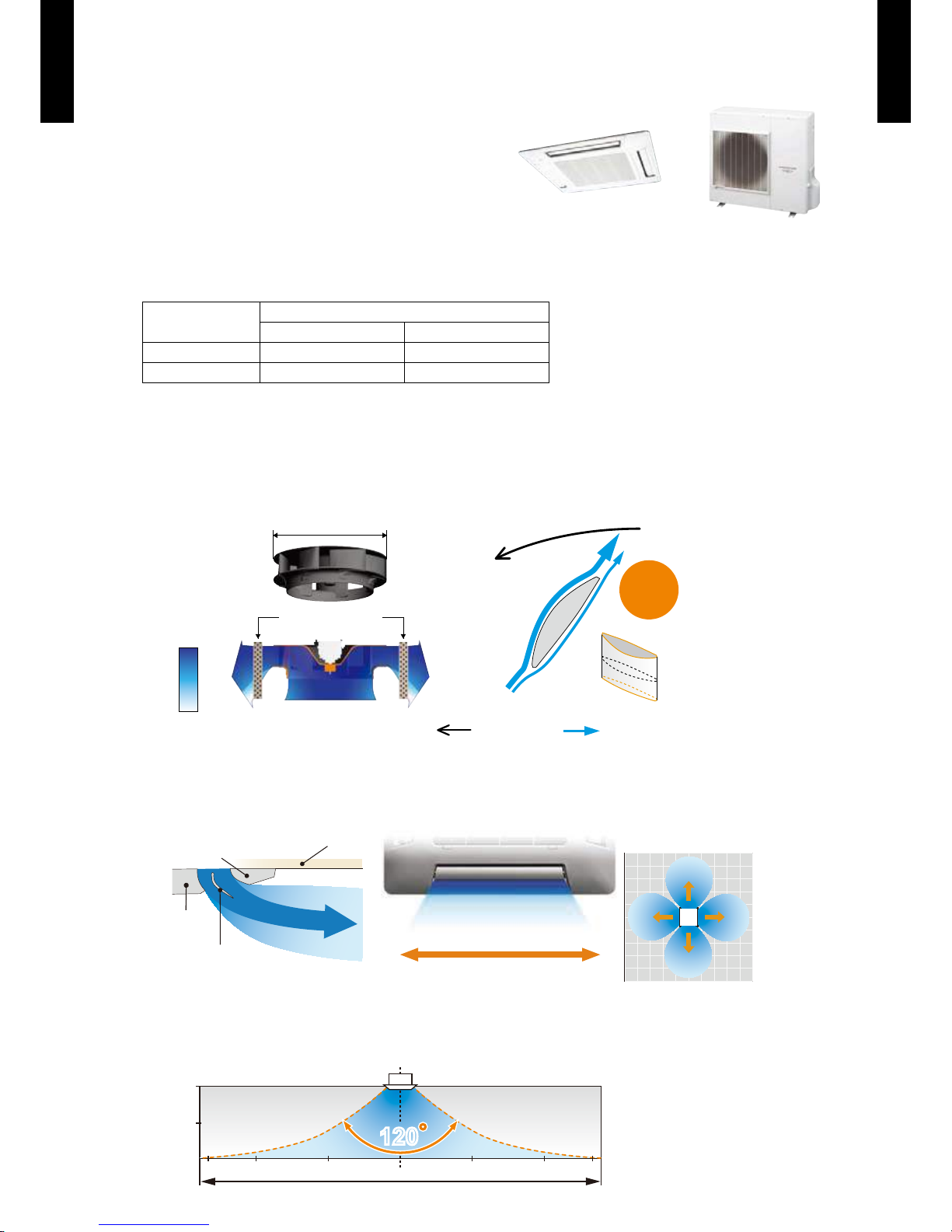
Adoption of high efficiency turbo fan
High efciency and quiet operation achieved by equaling the performance of the blade and air
passing the heat exchanger.
500mm
Wind
velocity
Fast
Slow
3-dimensional blade
: Spin direction : Airflow direction
No airflow
separation
Quiet
< Motor side >
Heat exchanger
Improvement of the airflow distribution
Making space between the ceiling, the air ows far and wide leaving the ceiling clean.
Rear part
Front part
Ceiling
Round louvre
Much less temperature irregularity
by spreading airflow widely
Bottom view
Wide & powerful airflow
1.5
3
7 5 3 73 5
Side view
Airflow range of 2m / s
120120
[ m ]
[ m ]
Page 5
- (01 - 02) -
CASSETTE TYPE
AU
G30-36LRLE
CASSETTE TYPE
AU
G30-36LRLE
Economy operation
z
The power consumption can be reduced.
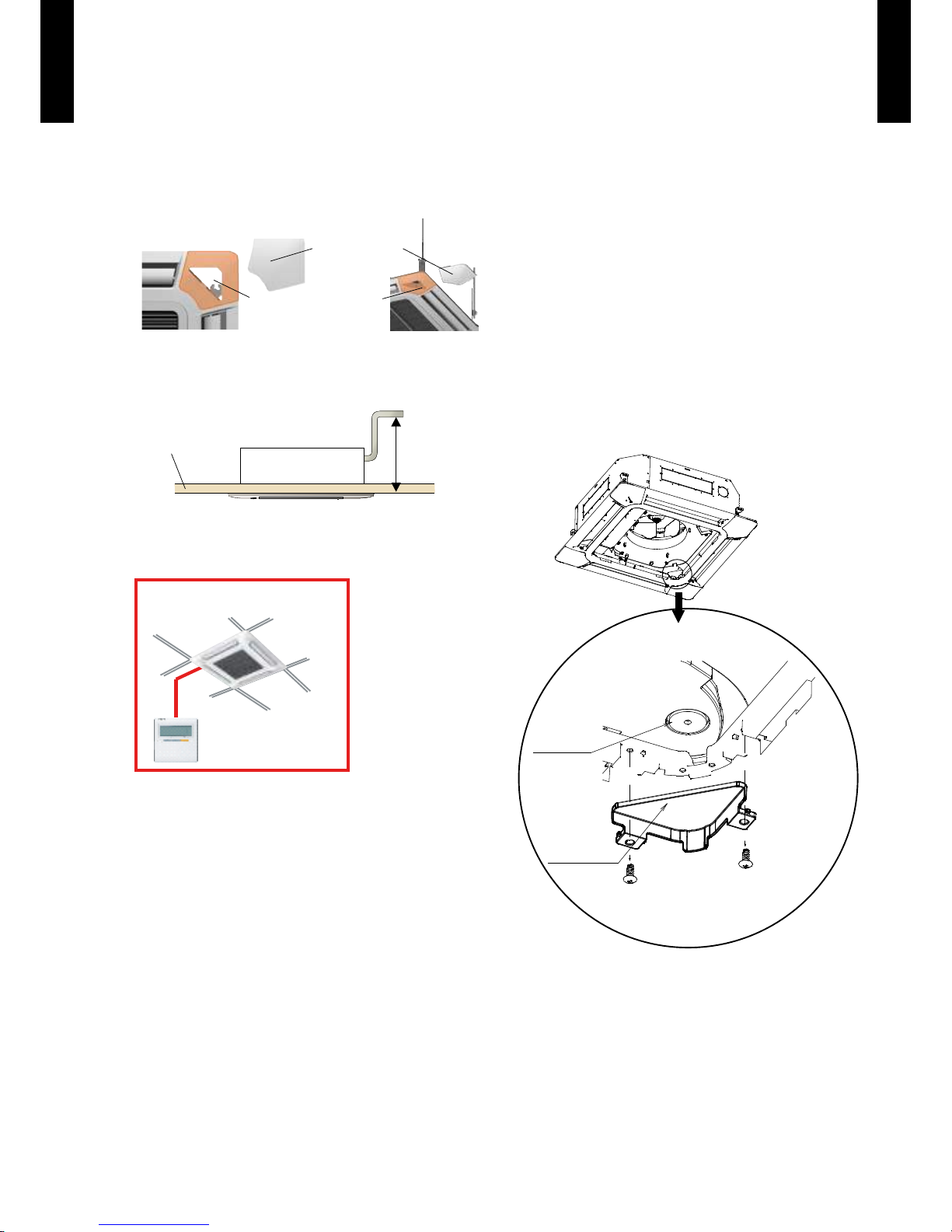
Improvement of installation & maintenance
z
Adjustment of hanger position is possible after installation
Mounting position of body can be ne adjusted after mounting the cassette grille.
Adjustment can be done
by just taking off the
corner part
Detachable grille
corner
High lift drain pump
z
850mm
Ceiling panel
Simplication of drain water check
z
Drain and contamination check are possible
without removing the cassette grille.
Can be easily checked by removing the drain
cover.
DRAIN CAP
DRAIN COVER
Easy installation
z
Easy setting by wired
remote controller
Page 6
- (01 - 03) -
CASSETTE TYPE
AU
G30-36LRLE
CASSETTE TYPE
AU
G30-36LRLE
FUNCTION SETTING
Outlet direction selection
z
Performs operation matched to the number of outlets when 4 directions are unnecessary and
outlets are blocked when the ceiling cassette is installed in a corner, etc.
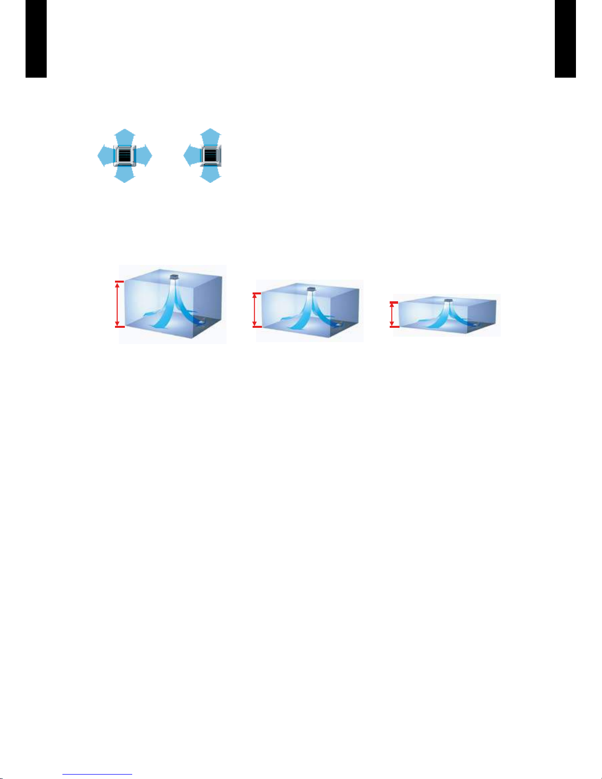
Ceiling switching function
z
Also delivers air to high ceilings by selecting the mode and raising the airow according to the
height of the ceiling.
Standard ...Operates at normal airow.
Mode 1 ...Airow becomes greater than normal.
Mode 2 ...Airow becomes smaller than normal.
Filter sign
z
The indoor unit displays signs to inform the user that it is time to clean the lter.
Cooling room temperature correction
z
Heating room temperature correction
z
Auto restart
z
The unit will restart automatically when the current returns even when there is a power
interruption during operation.
Room temperature sensor switching
z
Switches from room temperature judgment by room temperature sensor attached to indoor
unit body to room temperature judgment by room temperature sensor attached to the wired remote
controller.
4-way direction 3-way direction
4-way direction mode: Set when there are 4 outlets (shipped state).
3-way direction mode: Set when there are 3 outlets.
Low ceiling (Mode 2)
4.2m
3.2m
2.7m
High ceiling (Mode 1) Standard ceiling (Standard)
*1
*1 : AUG30L is 3.6m
Page 7
- (01 - 04) -
CASSETTE TYPE
AU
G30-36LRLE
CASSETTE TYPE
AU
G30-36LRLE
REMOTE CONTROLLER2.
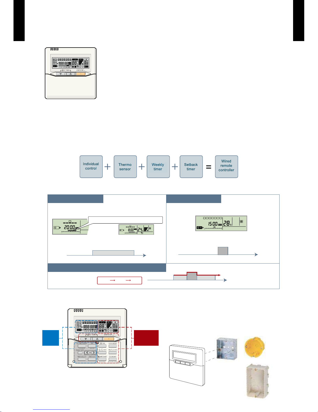
WIRED REMOTE CONTROLLER
FEATUR ES
Various timer setup available (ON / OFF / WEEKLY).
Equipped with weekly timer as standard function.
(Start/Stop function is twice per day for a week)
When setting up the timer, operation mode and temperature
setup can be changed.
When a failure occurs, the error code is displayed.
Error history. (Last 16 error codes can be accessed.)
The room temperature can be controlled by detecting the
temperature accurately with built-in thermo sensor.
Simple function setting
z
Setting of the air conditioner selection function is performed by remote controller.
High performance and compact size
z
Built-in timers
z
Weekly timer Setback timer
At "Weekly timer" + "Set back timer" setup
SUMOTUWETH FR SA
7
3126 9
15 18 21
SUMOTUWETH FR SA
7
3126 9
15 18 21
SUMOTUWETH FR SA
3126 9
15 18 21
Possible to set ON/OFF time to operate twice each day
of the week.
Setup scr een example
(Set to Wednes day: 8:00 to 20:00.)
Screen
after setup
Setup scr een example
(Set from Sunday to Satu rday: 12:00 to 15:00, 28 °C.)
Possible to set temperature for two time spans and
for each day of the week.
Easy-to-understand time bar display
24°C
0 3 6 9 12 15 18 21 Time
28°C
0 3 6 9 12 15 18 21 Time
28°C
24°C
0 3 6 9 12 15 18 21 Time
24°C 28°C 24°C
Easy-to-understand operation
z
[Variable timer control]
The operation/display sections are zoned
according to time and operation, enabling
variable programming to match application.
Simple installation
z
Components are compatible with standard
switch boxes. Flat back surface allows
equipment to be installed wherever it is
needed.
European
switch box
Timer
area
Operation
area
JIS box
Page 8
- (01 - 05) -
CASSETTE TYPE
AU
G30-36LRLE
CASSETTE TYPE
AU
G30-36LRLE
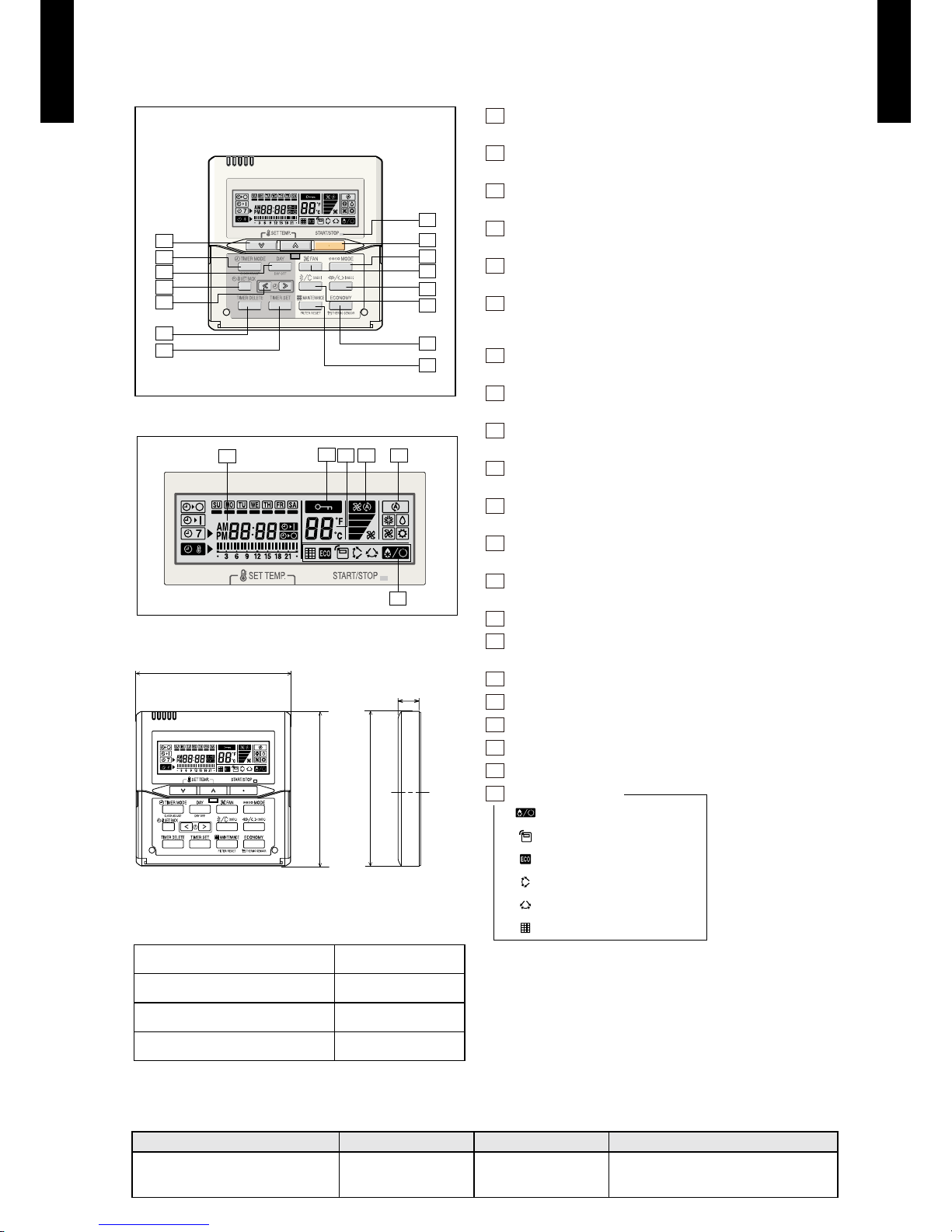
FUNCTIONS
Display panel
DIMENSION
SPECIFICATION
15
11
10
9
8
2
1
3
5
14
4
12
13
6
7
17
16
18
19
20
21
120
120
120
18
Side ViewFront View
SIZE (H × W × D mm) 120 × 120 × 18
WEIGHT (g) 160
CABLE LENGTH (m) 10
POWER (V) 12
1
START/STOP button
Pressed to start and stop operation.
2
SET TEMP. button
Selects the setting temperature.
3
MODE button
Selects the operating mode (AUTO, HEAT, FAN, COOL, DRY).
4
FAN button
Selects the fan speed (AUTO, QUIET, LOW, MED, HIGH).
5
ECONOMY (THERMO SENSOR) button
Turns the economy efcient mode on and off.
6
TIMER MODE (CLOCK ADJUST) button
Selects the timer mode (OFF TIM ER, ON TIMER, WEEKLY
TIMER). Sets the current time.
7
DAY (DAY OFF) button
Temporarily cancels one day timer.
8
SET BACK button
Pressed to select the set back timer.
9
Set time button
Pressed to set time.
10
TIMER DELETE button
Deletes the weekly timer schedule.
11
TIMER SET button
Sets the date, hour, minute and on-of f time.
12
Vertical airow direction and swing button
Push for two seconds to change the swing mode.
13
Horizontal airow direction and swing button
Push for two seconds to change the swing mode.
14
FILTER RESET button
15
Operation lamp
Lights during operation and when the timer is on.
16
Timer and clock display
17
Operation mode display
18
Fan speed display
19
Operation lock display
20
Temperature display
21
Function display
Defrost display
Thermo sensor display
Economy display
Vertical swing display
Horizontal swing display
Filter display
Note: Som e button operat ions may no t be availab le for all units or systems.
For detail s, pleas e see operation manual.
WIRING SPECIFICATIONS
Use Cable size Wire type Remarks
Remote controller cable
0.33 mm
2
(22 AWG)
Polar 3 core Use sheathed PVC cable
[ Unit : mm ]
Page 9

- (01 - 06) -
CASSETTE TYPE
AU
G30-36LRLE
CASSETTE TYPE
AU
G30-36LRLE
SPECIFICATIONS3.
Typ e
CASSET TE MODEL
INVERT ER HEATPU MP
Model na me AUG30LRLE AUG36LRLE
Power sour ce 230V~ 50 Hz
Available v oltage r ange 198-26 4V~ 50Hz
Capacity
Cooling
Rated
kW 8.50 10.00
Btu/h 29000 3410 0
Min.-Max.
kW 2.80 - 10.0 0 2.80 - 11.20
Btu/h 950 0 - 34100 9500 - 3 8200
Heating
Rated
kW 10.00 11.20
Btu/h 3 4100 38200
Min.-Max.
kW 2.70 - 11.20 2.70 - 12.70
Btu/h 9200 - 38 200 9200 - 43 300
Input powe r
Cooling
Rated
kW
2.65 3.1 2
Max. 3.88 4.22
Heating
Rated 2.77 3.02
Max. 3.88 4.56
Current
Cooling
Rated A
11.6 13.7
Heating 12.2 13. 3
EER Cooling
kW/kW
3.21 3. 21
COP Heating 3.61 3 .71
Moistur e removal l/h (pin ts/h) 2.5(5.3) 3.5(7.4)
Maximu m operat ing cur rent *
Cooling
A
17. 0 18. 5
Heating 17. 0 20.0
Fan
Airow
rate
Cooling
High
m
3
/h
1600 1800
Med 1400 1400
Low 1270 1270
Quiet 1150 1150
Heating
High 160 0 180 0
Med 1400 1400
Low 1270 1270
Quiet 1150 1150
Type × Q'ty Turbo Fan × 1
Motor out put W 80 80
Sound pre ssure lev el
Cooling
High
dB(A)
40 43
Med 38 38
Low 36 36
Quiet 32 32
Heating
High 4 0 43
Med 38 38
Low 36 3 6
Quiet 32 32
Heat excha nger ty pe
Dimensi ons (H × W × D)
mm
252 × 2030 × 2 6.6
252 × 2093 × 2 6.6
Fin pitch 1.2
Rows x Stag es 2 × 12
Pipe typ e Copper
Fin type Alumini um
Dimensions
( H×W×D)
Net
mm
288×840×840
Gross 360×960×985
Weight
Net
kg
26
Gross 31
Connec tion pip e
Size
Liquid
mm
Ø9.52 (3/ 8 in.)
Gas Ø15.88 (5/8 i n.)
Method Flare
Drain ho se
Material PVC
Size VP25 [Ø2 5(I.D.), Ø32(O.D.)]
Operat ion rang e
Cooling
°C 18 to 32
%RH 80 or les s
Heating °C 16 to 30
Casset te grill e
Model na me UTG-UGA-W
Material PS
Colour
WHITE
Approx imate col our of MU NSELL N 9. 25 /
Dimensions
(H × W × D)
Net
mm
50×950×950
Gross 115×1020×10 00
Weight
Net
kg
5.5
Gross 8.5
Remote co ntroll er type Wired [ Wirele ss (option)]
Note :
Speci cations are base d on the fol lowing c onditi ons.
Coolin g : Indoor t emperat ure of 27 °CD B / 19 °CW B.and out door tem peratur e of 35 °CD B/24 °CW B.
Heating : I ndoor te mperat ure of 20 °CD B / 15 °CWB .and out door temp eratur e of 7 °CDB/ 6 °CWB.
Pipe leng th : 5 m, Heig ht diff erence : 0 m .(Outdoor u nit - Indo or unit)
The maxi mum cur rent and th e maximu m input val ue are max imum value s when operated wit hin the op eratio n range.
*The ma ximum cu rrent is t he total c urrent of i ndoor un it and outd oor unit .
Page 10

- (01 - 07) -
CASSETTE TYPE
AU
G30-36LRLE
CASSETTE TYPE
AU
G30-36LRLE
Model name AUG30LRLE AUG36LRLE
Energy ef ciency class
Cooling A++ A++
Heating (Average) A+ A+
Pdesign
Cooling
kW
8.5(35°C) 10.0(35°C)
Heating (Average) 8.0(-10°C) 8.7(-10°C)
SEER Cooling
kWh/kWh
6.50 6.30
SCOP Heating (Average) 4.30 4.20
Annual energy consumption
QCE
kWh/a
458 555
QHE (Average) 2604 2897
Sound power level
Cooling
High dB (A)
54 57
Heating 54 57
Page 11
- (01 - 08) -
CASSETTE TYPE
AU
G30-36LRLE
CASSETTE TYPE
AU
G30-36LRLE
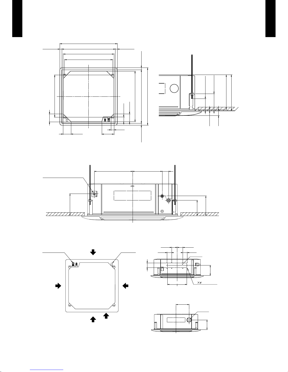
DIMENSIONS4.
MODELS : AUG30LRLE, AUG36LRLE
Ceiling opening and hanging bolt pitch
z
(Unit : mm)
Refrigerant piping and drain piping positions
z
Airow split-ow duct and fresh air inlet positions
z
288 mm
298 mm
40 mm
10 mm
140 - 145 mm
50 - 100 mm
950 mm(Panel frame)
mm 54 - 02mm 54 - 02
50 mm
80 mm
130 mm
130 mm
130 mm
200 mm
840 mm(Body frame)
795 mm(Hanging bolt pitch)
699 mm(Hanging bolt pitch)
860 - 910 mm(Ceiling opening)
950 mm(Panel frame)
mm 54 - 02mm 54 - 02
840 mm(Body frame)
860 - 910 mm(Ceiling opening)
60 mm278 mm358 mm
140 mm
180 mm
200 mm
Drain pipe
(Connect the attached drain hose)
2.5 mm screw
352 mm
100 mm
83 mm83 mm
90 mm
100 mm
mm 581
Airflow split-flow duct connecting port
Airflow split-flow duct connecting port
Airflow split-flow duct connecting port
Fresh air inlet position
Drain pipe
Refrigerant pipe
Detailed diagram of branched duct connecting port
(4 sides)
Cut out
Airflow split-flow duct connecting port
10
250 mm
185 mm
Cut out
Fresh air inlet position
Page 12

- (01 - 09) -
CASSETTE TYPE
AU
G30-36LRLE
CASSETTE TYPE
AU
G30-36LRLE
INSTALLATION PLACE
(Unit : mm)
3-way directions setting
z
(Unit : mm)
To set “3-way directions”, the air outlet shutter plate (UTR-YDZC) sold separately must be installed
and “outlet-direction” switched to “3-way” by remote controller.
1,500
or more
1,000 or more
1,800 or more
Obstruction
3,000 or more
Strong and durable ceiling
Floor
Ceiling mode “Low” : 2.7 m
Ceiling mode “Standard” : 3.2 m
Ceiling mode “High” : 3.6 m (30 model)
4.2 m (36 model)
100 or more
Page 13
- (01 - 10) -
CASSETTE TYPE
AU
G30-36LRLE
CASSETTE TYPE
AU
G30-36LRLE
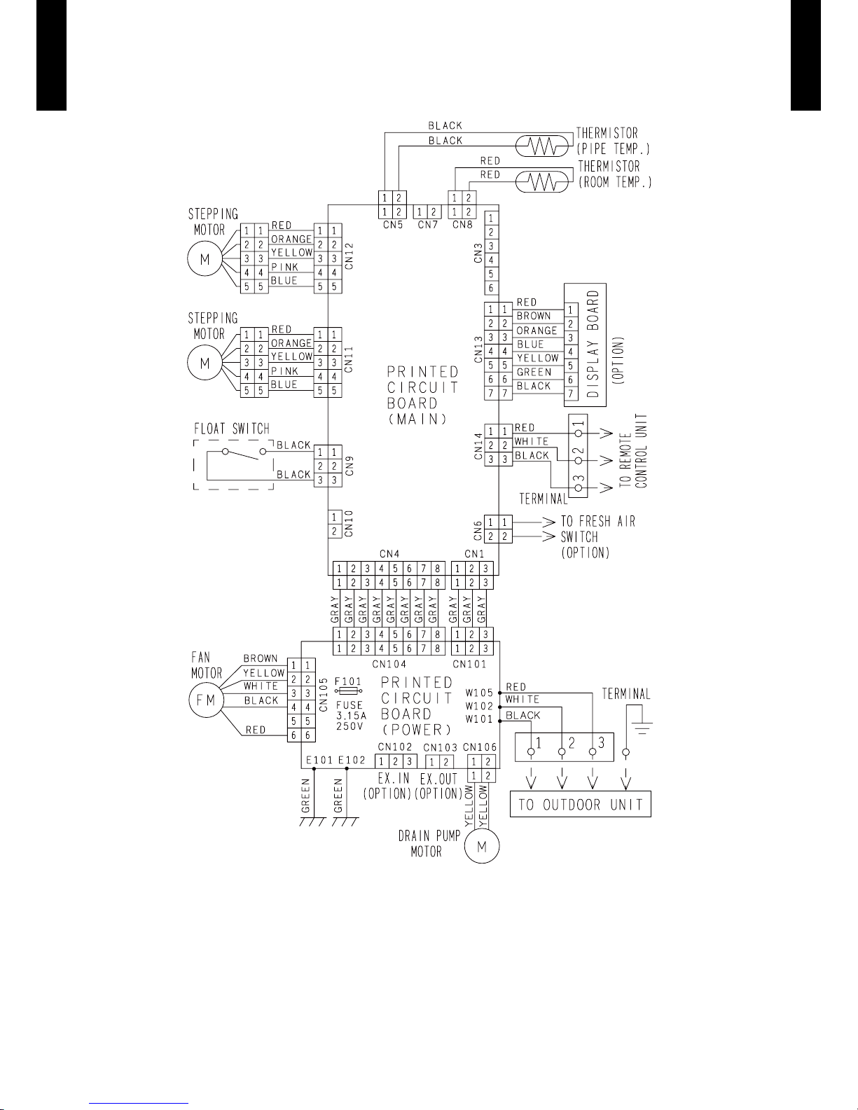
WIRING DIAGRAMS5.
MODELS : AUG30LRLE, AUG36LRLE
Page 14
- (01 - 11) -
CASSETTE TYPE
AU
G30-36LRLE
CASSETTE TYPE
AU
G30-36LRLE
CAPACITY TABLE6.
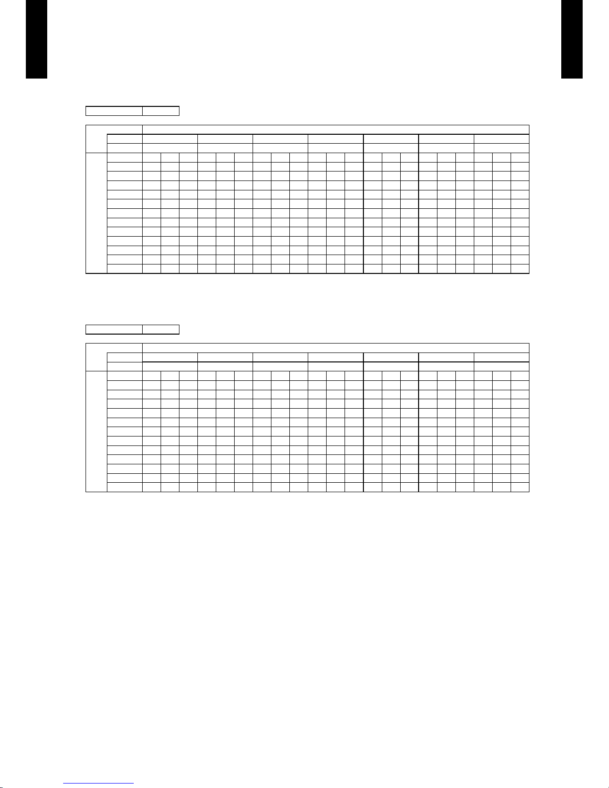
COOLING CAPACITY6-1.
This table is created using the maximum capacity.
MODEL : AUG30LRLE
MODEL : AUG36LRLE
AFR : Air Fl ow Rate (m3/min)
TC : Total Capaci ty (kW)
SHC : Sens ible Hea t Capaci ty (kW)
IP : Input Pow er (kW)
AFR 26.7
Indoor t empera ture
°CDB 18 21 23 25 27 29 32
°CWB 12 15 16 18 19 21 23
Outdoo r temper ature
°CDB TC SHC IP TC SHC IP TC SHC IP TC SHC IP TC SH C IP TC SHC IP TC SHC IP
-15 8.67 6.58 1.20 9.66 6.62 1.22 9.9 9 7.20 1. 22 10.65 7.22 1.24 10.98 7.80 1. 24 11.64 7.77 1.25 12.29 8. 27 1. 27
-10 8.52 6.38 1.64 9.49 6.42 1.66 9.81 6.9 8 1.67 10.46 7.00 1.69 10.79 7.56 1.70 11.43 7.53 1.71 12.08 8.02 1.73
0 8.12 6. 26 2.11 9.04 6.30 2 .15 9.35 6.85 2.16 9.97 6.87 2 .18 10.28 7.42 2.19 10.89 7.39 2.21 11.51 7.87 2. 23
5 7.99 6.11 2.14 8 .90 6.14 2.17 9.21 6.68 2.19 9.81 6.70 2. 21 10.12 7.23 2.22 10.72 7.21 2.24 11.33 7.68 2. 26
10 7.96 6.19 2.19 8.87 6.23 2.23 9.17 6.77 2.24 9.77 6.79 2.2 6 10.07 7.34 2.27 10.68 7.31 2.2 9 11.28 7.78 2.32
15 8.63 6.48 2.41 9.62 6.52 2.45 9.94 7.09 2.4 6 10.60 7. 11 2.49 10.9 3 7.68 2 .50 11.58 7.65 2.5 3 12.24 8 .14 2. 55
20 9.8 2 7.03 2 .97 10.94 7.07 3.01 11.31 7.69 3. 03 12.06 7. 71 3.0 6 12.4 3 8.33 3.08 13.18 8.30 3.11 13.92 8.8 4 3.1 4
25 9.4 8 6 .89 3.31 10.56 6.93 3.3 6 10.92 7.53 3.38 11.64 7.56 3. 41 12.00 8.16 3 .43 12.72 8 .13 3.4 6 13.44 8.66 3.50
30 8.81 6.70 3.3 4 9 .81 6.74 3.39 10.15 7.32 3. 41 10.81 7.35 3.44 11.15 7.93 3. 46 11.82 7.90 3.50 12.49 8.4 2 3. 53
35 7.90 6.1 2 3.3 5 8. 80 6.16 3.40 9.10 6.69 3.42 9.70 6.71 3.45 10.0 0 7.25 3.47 10.60 7.22 3.51 11.20 7.69 3. 54
40 6 .16 5.13 2. 94 6.86 5.16 2.99 7.09 5.61 3.01 7.56 5.6 3 3.0 4 7.80 6 .08 3.05 8.26 6.05 3.08 8.73 6.4 5 3.11
46 5.4 4 4. 92 2.91 6.06 4.95 2.96 6.27 5.39 2.97 6.68 5.40 3.0 0 6. 89 5 .83 3.02 7.30 5.81 3.05 7.7 1 6.19 3.08
AFR 30.0
Indoor t empera ture
°CDB 18 21 23 25 27 29 32
°CWB 12 15 16 18 19 21 23
Outdoo r temper ature
°CDB TC SHC IP TC SHC IP TC SHC IP TC SHC IP TC SH C IP TC SHC IP TC SHC IP
-15 9.33 7.37 1.29 10.39 7.41 1.31 10.74 8.06 1.32 11.45 8.08 1.33 11.80 8.7 3 1. 34 12.51 8.70 1.35 13.2 2 9.26 1.36
-10 9.22 7.23 1.69 10.27 7.27 1.71 10.62 7.90 1.72 11.32 7.93 1.74 11.67 8.5 6 1.75 12.37 8.53 1.77 13.07 9.08 1.78
0 8 .77 7.1 3 2 .18 9.7 7 7.1 7 2.2 2 10.10 7.80 2 .23 10.77 7.82 2.2 5 11.10 8.45 2.26 11.77 8.41 2.2 9 12.44 8.96 2.31
5 8. 69 6.98 2.25 9.68 7.02 2.28 10.01 7.64 2. 29 10.67 7.66 2.32 11.00 8.2 7 2. 33 11.66 8.24 2.35 12.32 8 .78 2 .38
10 8 .62 7.06 2.25 9.60 7.10 2. 29 9.93 7.72 2.30 10.58 7.75 2.3 2 10.91 8.37 2.34 11.56 8.33 2.3 6 12.22 8.88 2 .38
15 9.17 7.1 7 2.42 10. 21 7.22 2.46 10.56 7.85 2.47 11.25 7.87 2. 50 11.60 8.50 2.51 12.30 8. 47 2. 54 13.00 9.02 2.5 6
20 10.70 7.92 2. 99 11.92 7.97 3.03 12.3 3 8.66 3 .05 13.14 8.6 9 3.0 8 13.54 9.39 3.10 14.36 9.3 5 3.1 3 15.17 9.96 3.16
25 10.6 4 8.02 3.32 11.86 8.0 6 3. 38 12.26 8.77 3.39 13.07 8.79 3.4 3 13.47 9.50 3.45 14.28 9.46 3.4 8 15.09 10.08 3.51
30 10.24 7.7 6 4.05 11.40 7.81 4.11 11.79 8.49 4.13 12.57 8.51 4 .17 12.96 9.1 9 4.1 9 13.73 9.1 6 4. 24 14.51 9.75 4.28
35 8.8 5 6 .78 4.03 9.86 6.82 4.10 10.19 7.42 4.1 2 10.8 6 7.44 4 .16 11.20 8.04 4.18 11.87 8.01 4.2 2 12.54 8.53 4.26
40 6.8 0 5. 96 3.09 7.58 6.00 3 .14 7.84 6.52 3.16 8.35 6.5 4 3.19 8 .61 7.07 3 .20 9.13 7.04 3.24 9.65 7.50 3.2 7
46 6.11 5.8 4 2. 96 6.81 5.87 3.01 7.04 6.39 3.02 7.50 6. 41 3.0 5 7. 74 6.92 3.07 8.2 0 6. 89 3.10 8.67 7.34 3 .13
Page 15
- (01 - 12) -
CASSETTE TYPE
AU
G30-36LRLE
CASSETTE TYPE
AU
G30-36LRLE
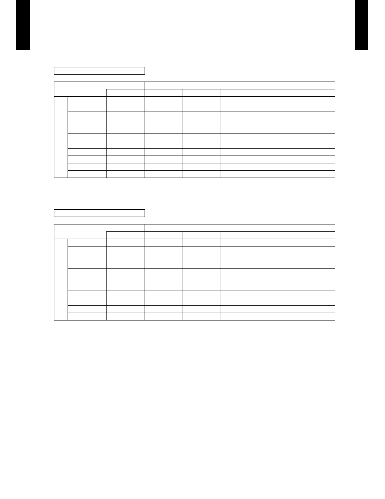
HEATING CAPACITY6-2.
This table is created using the maximum capacity.
MODEL : AUG30LRLE
MODEL : AUG36LRLE
AFR : Air Fl ow Rate (m3/min)
TC : Total Capaci ty (kW)
IP : Input Pow er (kW)
AFR 26.7
Indoor temperature
°CDB 16 18 20 22 24
Outdoor temperature
°CDB °CWB TC IP TC IP TC IP TC IP TC IP
-15 -16 8.34 3.37 8.14 3.4 4 7.94 3.51 7.75 3.58 7.55 3.65
-10 -11 8.79 3.38 8.58 3.45 8.37 3.52 8.16 3.59 7.95 3.66
-5 -7 9.55 3.41 9.32 3.48 9.0 9 3.55 8.86 3.62 8.64 3.69
0 -2 10.12 3.37 9.88 3.44 9.64 3.51 9.40 3.58 9.16 3.65
5 3 11 .23 3.35 10.96 3.42 10.69 3.49 10.43 3.56 10.16 3.62
7 6 11.76 3.33 11.48 3.40 11. 20 3.47 10.92 3.54 10.64 3.61
10 8 12.12 3.30 11.83 3.37 11. 54 3.44 11. 25 3.51 10.96 3.57
15 10 10.86 2.52 10.60 2.57 10.34 2.62 10.09 2.67 9.83 2.71
20 15 10.87 2.23 10.61 2.28 10.35 2.33 10.09 2.37 9.83 2.41
24 18 11.31 2.25 11. 04 2.3 0 10.78 2.34 10.51 2.39 10.24 2.43
AFR 30.0
Indoor temperature
°CDB 16 18 20 22 24
Outdoor temperature
°CDB °CWB TC IP TC IP TC IP TC IP TC IP
-15 -16 9.63 3.92 9.40 4.00 9.17 4.08 8.94 4.17 8.71 4.25
-10 -11 9.70 3.96 9.47 4.04 9.24 4.13 9.01 4.21 8.77 4.29
-5 -7 10.69 4.07 10.43 4.16 10.18 4.24 9.92 4.33 9.67 4.41
0 -2 12.54 3.99 12.24 4.08 11.9 4 4.16 11.64 4.24 11. 34 4.33
5 3 13 .18 3.81 12.87 3.89 12.55 3.97 12 .24 4.05 11.92 4.13
7 6 13.34 3.36 13.02 3.43 12.70 3.50 12.38 3.57 12.07 3.64
10 8 13.74 3.19 13.42 3.26 13.09 3.33 12.76 3.39 12.43 3.46
15 10 12.26 2.55 11. 97 2.60 11.67 2.65 11.38 2.71 11.09 2.75
20 15 12.28 2.26 11.99 2.31 11. 69 2.36 11.40 2.40 11.11 2.44
24 18 12. 80 2.28 12.49 2.32 12.19 2.37 11. 88 2.42 11. 58 2.46
Page 16

- (01 - 13) -
CASSETTE TYPE
AU
G30-36LRLE
CASSETTE TYPE
AU
G30-36LRLE
FAN PERFORMANCE7.
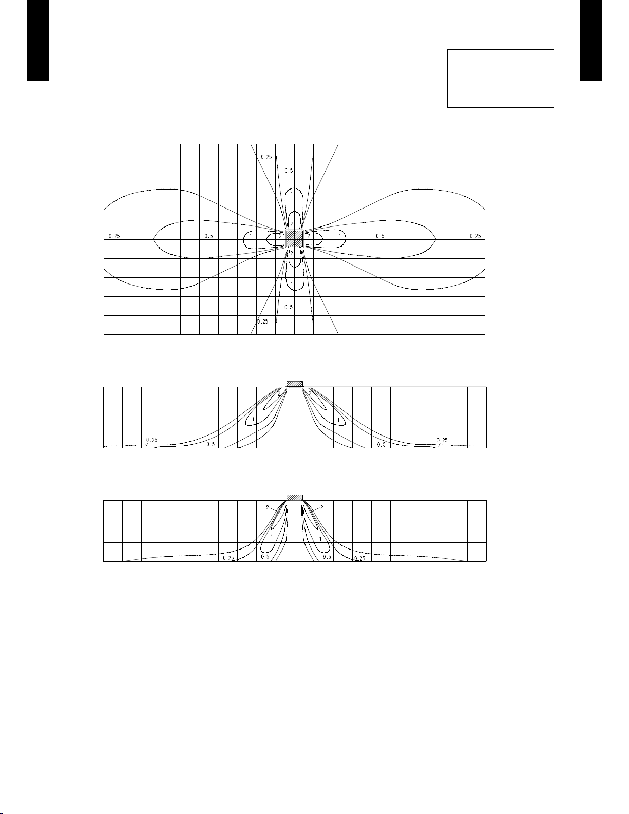
AIR VELOCITY DISTRIBUTION7-1.
STANDARD MODE7-1-1.
MODEL : AUG30LRLE
4-way air outlet
z
Note:
Condition
Fan speed : High
Operation mode : FAN
Ceiling mode : Standard
5
4
3
2
1
0
1
2
3
4
5
Unit : m/s(m)
(m)
TOP VIEW
VERTICA L LOUVER
: Upward
3.2
2
1
0
Unit : m/s(m)
(m)
SIDE VIE W
VERTICA L LOUVER
: Upward
3.2
2
1
0
Unit : m/s(m)
(m)
SIDE VIE W
VERTICA L LOUVER
: Downwar d
10 9 8 7 6 5 4 3 2 1 0 1 2 3 4 5 6 7 8 9 10
10 9 8 7 6 5 4 3 2 1 0 1 2 3 4 5 6 7 8 9 10
10 9 8 7 6 5 4 3 2 1 0 1 2 3 4 5 6 7 8 9 10
Page 17
- (01 - 14) -
CASSETTE TYPE
AU
G30-36LRLE
CASSETTE TYPE
AU
G30-36LRLE
MODEL : AUG36LRLE
4-way air outlet
z
Note:
Condition
Fan speed : High
Operation mode : FAN
Ceiling mode : Standard
5
4
3
2
1
0
1
2
3
4
5
Unit : m/s(m)
(m)
TOP VIEW
VERTICA L LOUVER
: Upward
3.2
2
1
0
Unit : m/s(m)
(m)
SIDE VIE W
VERTICA L LOUVER
: Upward
3.2
2
1
0
Unit : m/s(m)
(m)
SIDE VIE W
VERTICA L LOUVER
: Downwar d
10 9 8 7 6 5 4 3 2 1 0 1 2 3 4 5 6 7 8 9 10
10 9 8 7 6 5 4 3 2 1 0 1 2 3 4 5 6 7 8 9 10
10 9 8 7 6 5 4 3 2 1 0 1 2 3 4 5 6 7 8 9 10
Page 18

- (01 - 15) -
CASSETTE TYPE
AU
G30-36LRLE
CASSETTE TYPE
AU
G30-36LRLE
MODEL : AUG30LRLE
3-way air outlet
z
Note:
Condition
Fan speed : High
Operation mode : FAN
Ceiling mode : Standard
5
4
3
2
1
0
1
2
3
4
5
Unit : m/s(m)
(m)
TOP VIEW
VERTICA L LOUVER
: Upward
3.2
2
1
0
Unit : m/s(m)
(m)
SIDE VIE W
VERTICA L LOUVER
: Upward
3.2
2
1
0
Unit : m/s(m)
(m)
SIDE VIE W
VERTICA L LOUVER
: Downwar d
10 9 8 7 6 5 4 3 2 1 0 1 2 3 4 5 6 7 8 9 10
10 9 8 7 6 5 4 3 2 1 0 1 2 3 4 5 6 7 8 9 10
10 9 8 7 6 5 4 3 2 1 0 1 2 3 4 5 6 7 8 9 10
Page 19

- (01 - 16) -
CASSETTE TYPE
AU
G30-36LRLE
CASSETTE TYPE
AU
G30-36LRLE
MODEL : AUG36LRLE
3-way air outlet
z
Note:
Condition
Fan speed : High
Operation mode : FAN
Ceiling mode : Standard
5
4
3
2
1
0
1
2
3
4
5
Unit : m/s(m)
(m)
TOP VIEW
VERTICA L LOUVER
: Upward
3.2
2
1
0
Unit : m/s(m)
(m)
SIDE VIE W
VERTICA L LOUVER
: Upward
3.2
2
1
0
Unit : m/s(m)
(m)
SIDE VIE W
VERTICA L LOUVER
: Downwar d
10 9 8 7 6 5 4 3 2 1 0 1 2 3 4 5 6 7 8 9 10
10 9 8 7 6 5 4 3 2 1 0 1 2 3 4 5 6 7 8 9 10
10 9 8 7 6 5 4 3 2 1 0 1 2 3 4 5 6 7 8 9 10
Page 20

- (01 - 17) -
CASSETTE TYPE
AU
G30-36LRLE
CASSETTE TYPE
AU
G30-36LRLE
SPECIAL UPWARD MODE7-1-2.
MODEL : AUG30LRLE
4-way air outlet
z
MODEL : AUG36LRLE
4-way air outlet
z
Note:
Condition
Fan speed : High
Operation mode : FAN
Ceiling mode : Standard
10 9 8 7 6 5 4 3 2 1 0 1 2 3 4 5 6 7 8 9 10
10 9 8 7 6 5 4 3 2 1 0 1 2 3 4 5 6 7 8 9 10
(m)
Unit : m/s
3.2
2
1
0
(m)
SIDE VIE W
VERTICA L LOUVER
: Sp ecial up ward
(m)
SIDE VIE W
VERTICA L LOUVER
: Sp ecial up ward
Unit : m/s(m)
3.2
2
1
0
Page 21

- (01 - 18) -
CASSETTE TYPE
AU
G30-36LRLE
CASSETTE TYPE
AU
G30-36LRLE
AIRFLOW7-2.
4-WAY OUTLET7-2-1.
MODEL : AUG30LRLE
Cooling / Heating
z
MODEL : AUG36LRLE
Cooling / Heating
z
Fan speed
Number of
rotations
(r.p.m)
Airow
HIGH 570
m
3
/h 1600
l/s 444
CFM 942
MED 510
m
3
/h 1400
l/s 389
CFM 824
LOW 470
m
3
/h 1270
l/s 353
CFM 747
QUIET 420
m
3
/h 1150
l/s 319
CFM 677
Fan speed
Number of
rotations
(r.p.m)
Airow
HIGH 640
m
3
/h 1800
l/s 500
CFM 1059
MED 510
m
3
/h 1400
l/s 389
CFM 824
LOW 470
m
3
/h 1270
l/s 353
CFM 747
QUIET 420
m
3
/h 1150
l/s 319
CFM 677
Page 22

- (01 - 19) -
CASSETTE TYPE
AU
G30-36LRLE
CASSETTE TYPE
AU
G30-36LRLE
3-WAY OUTLET7-2-2.
MODEL : AUG30LRLE
Cooling / Heating
z
MODEL : AUG36LRLE
Cooling / Heating
z
*Airow can be changed according to the direction in which the outlet is blocked.
Fan speed
Number of
rotations
(r.p.m)
Airow
*Max. *Min.
HIGH 610
m
3
/h 1550 1350
l/s 431 375
CFM 912 794
MED 550
m
3
/h 1350 1200
l/s 375 333
CFM 794 706
LOW 510
m
3
/h 1250 1100
l/s 347 306
CFM 736 647
QUIET 460
m
3
/h 1100 950
l/s 306 264
CFM 647 559
Fan speed
Number of
rotations
(r.p.m)
Airow
*Max. *Min.
HIGH 680
m
3
/h 1700 1550
l/s 472 431
CFM 1000 912
MED 550
m
3
/h 1350 1200
l/s 375 333
CFM 794 706
LOW 510
m
3
/h 1250 1100
l/s 347 306
CFM 736 647
QUIET 460
m
3
/h 1100 950
l/s 306 264
CFM 647 559
Page 23

- (01 - 20) -
CASSETTE TYPE
AU
G30-36LRLE
CASSETTE TYPE
AU
G30-36LRLE
FRESH AIR7-3.
MODELS : AUG30LRLE, AUG36LRLE
Airow volume - Static pressure of Fresh air intake characteristic
z
Installation
z
Fresh air inlet position
Duct ange *2
Flexible duct *2
Flexible duct *2
Fan *2
Insulation *1
250 mm
185 mm
2.5 mm screw4
70 mm
62 mm
62 mm
cut out
Fresh air inlet position (A)
View (A)
Fresh air inlet position
Refrigerant pipe Drain pipe
*1 : In case of fresh air intake, please remove the insulation.
*2 : Locally procured parts
98
49
0
10
8
6
4
2
0
0 0.1 0.2 0.3 0.4 0.5 0.6 0.7
Airow (m3/min)
Duct static pressure (Pa)
Duct static pressure (mmAq)
Duct
(Inner Dia. ø70mm)
Static pressure required
to take in fresh air
Duct Fan
Page 24

- (01 - 21) -
CASSETTE TYPE
AU
G30-36LRLE
CASSETTE TYPE
AU
G30-36LRLE
DUCT CONNECTION7-4.
MODELS : AUG30LRLE, AUG36LRLE
Outlet air
z
98
49
0
10
9
8
7
6
5
4
3
2
1
0
0 2 4 6 8 10 12 14
Duct static pressure (mmAq)
Airow (m3/min)
AUG36LRLE
Duct static pressure (Pa)
Fan speed High
Fan speed
Quiet
L=10m
L=5m
L=1m
98
49
0
10
9
8
7
6
5
4
3
2
1
0
0 2 4 6 8 10 12 14
Duct static pressure (mmAq)
Airow (m3/min)
AUG30LRLE
Duct static pressure (Pa)
Fan speed High
Fan speed
Quiet
L=10m
L=5m
L=1m
Duct
(Inside Dia. 350mm×100mm)
L
Page 25

- (01 - 22) -
CASSETTE TYPE
AU
G30-36LRLE
CASSETTE TYPE
AU
G30-36LRLE
PRECAUTIONS WHILE CONNECTING AIR OUTLET DUCT
z
Connect the air outlet duct to maximum two locations among the four duct
connection locations. (Do not connect ducts to three or more locations.)
z
Blow-off pattern when a branch duct is installed
Bi-directional branching, main unit bi-directional branching
z
Once the location where the duct is to be connected is decided,
always be sure to close the outlets in the same direction.
A
B
C
D
Close Close
Branch
Branch
Close
Close
Branch
Branch
DUCT (Locally procured parts)
Close the outlet here.
* Use only af ter closing the outlet of the cassette on the
side of w hic h th e duct is used, using the “Air outlet
shutter plate (UTR-YDZC)”.
Page 26

- (01 - 23) -
CASSETTE TYPE
AU
G30-36LRLE
CASSETTE TYPE
AU
G30-36LRLE
OPERATION NOISE (SOUND PRESSURE)8.
NOISE LEVEL CURVE8-1.
MODEL : AUG30LRLE
Condition
Ceiling mode : Standard
Air outlet : 4-way air outlet
HIGH
QUIET
HIGH
QUIET
HIGH
QUIET
HIGH
QUIET
Heating
z
Octave ba nd soun d pressu re level, d B:(0dB= 0.00 02µba r)
Octave ba nd center frequ ency,Hz
80
70
60
50
40
30
20
10
0
63 125 250 500 1,000 2,000 4,000 8 ,000
NC-65
NC-60
NC-55
NC-50
NC-45
NC-40
NC-35
NC-30
NC-25
NC-20
NC -15
Heating
z
Octave ba nd soun d pressu re level, d B:(0dB= 0.00 02µba r)
Octave ba nd center frequ ency,Hz
80
70
60
50
40
30
20
10
0
63 125 250 50 0 1,000 2,000 4,000 8,000
NC-65
NC-60
NC-55
NC-50
NC-45
NC-40
NC-35
NC-30
NC-25
NC-20
NC -15
Octave ba nd soun d pressu re level, d B:(0dB= 0.00 02µba r)
Octave ba nd center frequ ency,Hz
80
70
60
50
40
30
20
10
0
63 125 250 50 0 1,000 2,000 4,000 8,000
MODEL : AUG36LRLE
Cooling
z
NC-65
NC-60
NC-55
NC-50
NC-45
NC-40
NC-35
NC-30
NC-25
NC-20
NC -15
Cooling
z
Octave ba nd soun d pressu re level, d B:(0dB= 0.00 02µba r)
Octave ba nd center frequ ency,Hz
80
70
60
50
40
30
20
10
0
63 125 250 50 0 1,000 2,000 4,000 8,000
NC-65
NC-60
NC-55
NC-50
NC-45
NC-40
NC-35
NC-30
NC-25
NC-20
NC -15
Page 27

- (01 - 24) -
CASSETTE TYPE
AU
G30-36LRLE
CASSETTE TYPE
AU
G30-36LRLE
SOUND LEVEL CHECK POINT8-2.
Microphone
Microphone
CENTER
1.5m
Page 28

- (01 - 25) -
CASSETTE TYPE
AU
G30-36LRLE
CASSETTE TYPE
AU
G30-36LRLE
ELECTRIC CHARACTERISTICS9.
Model Name AUG30LRLE AUG36LRLE
Power Supply
Voltage V 230 ~
Frequency Hz 50
Max Operating Current (Indoor unit) A 0.7
*1) Wiring Spec.
Connection Cable mm
2
1.5
*2) Limited wiring length m 51
*1) Wiring Spec.
Selected Sample
(Selected based on Japan Electrotechnical Standards and Codes Committee E0005)
*2) Limited wiring length:
This is the wiring length in case voltage descent is less than 2%.
When the wiring length becomes long, please select the wiring of a more larger diameter.
Page 29

- (01 - 26) -
CASSETTE TYPE
AU
G30-36LRLE
CASSETTE TYPE
AU
G30-36LRLE
SAFETY DEVICES10.
Protection form
Model
AUG30LRLE AUG36LRLE
Circuit protection Current fuse (PCB) 250V 3.15A
Fan motor protection
Thermal protection
program
110
+15
-10
°C OFF
105
+15
-10
°C ON
Page 30

- (01 - 27) -
CASSETTE TYPE
AU
G30-36LRLE
CASSETTE TYPE
AU
G30-36LRLE
EXTERNAL INPUT & OUTPUT11.
Connector INPUT OUTPUT REMARKS
CN102 Control input —
See external
input/output settings for
details.
CN103 — Operation status output
CN6 — Fresh air control output
EXTERNAL INPUT11-1.
CONTROL INPUT (Operation/Stop or Forced stop)
The air conditioner can be remotely operated by means of the following on-site work.
"Operation/Stop" mode or "Forced stop" mode can be selected with function setting of indoor unit.
Unit operation is started at the following contents by adding the contact input of a commercial ON/OFF switch to a
connector on the external control PC board and turning it ON.
Unit operation Initial setting after power is ON Starting mode other than initial setting
Operation mode Auto changeover Mode at previous operation
Set temperature 24°C Temperature at previous operation
Air ow mode AUTO Mode at previous operation
Up-down air direction (swing) Standard air direction (swing OFF) Air direction at previous operation
Left-right air direction (swing) Standard air direction (swing OFF) Air direction at previous operation
Circuit diagram example
z
Indoor unit
control PC board Connected unit
Ex.) Switch
Connector
1
3
Signal
Field supply
* Make the distance from the PC board to the connected unit within 10m.
*10 m
Contact capacity : 5VDC or more, 15mA or more.
Please use non-polar relays and switches.
When function setting is in "Operation/Stop" mode ●
Input signal
Indoor unit
Operation
Stop
ON
OFF
When function setting is in "Forced stop" mode ●
Remote controller
ON ON ON
Input signal
Indoor unit
Command
Remote control
operation invalidity
ON
OFF
Operation
Stop
Forced stop
Normal
Parts (Optional)
z
Model name
UT Y-XWZ X
Wire (External input)
Page 31

- (01 - 28) -
CASSETTE TYPE
AU
G30-36LRLE
CASSETTE TYPE
AU
G30-36LRLE
EXTERNAL OUTPUT11-2.
OPERATION STATUS OUTPUT
An air conditioner operation status signal can be output.
Circuit diagram example
z
Field supply
Ex.)Display
Indoor unit
control PC board
Connected unit
Ex.)Relay unit
1
2
Signal
Relay
power
supply
V
Connector
* Make the distance from the PC board to the connected unit within 10m.
Relay spec. : Max.24VDC, 10mA to less than 500mA.
*10 m
24V DC
Indoor unit
Output signal
ON
OFF
Operation
Stop
Parts (Optional)
z
Model name
UT Y-XWZ X
Wire (External output)
Page 32

- (01 - 29) -
CASSETTE TYPE
AU
G30-36LRLE
CASSETTE TYPE
AU
G30-36LRLE
FRESH AIR CONTROL OUTPUT
A signal linked to air conditioner indoor fan ON can be output.
* However, signal becomes OFF during cold air prevention control operation.
Circuit diagram example
z
Field supply
Indoor unit
control PC board
Connector
1
12 V
on/off
2
Signal
Relay
power
supply
* Make the distance from the PC board to the connected unit within 10m.
Relay spec. : Rated 12VDC, 50mA or less.
Ex.) Fan
Connected unit
Ex.) Relay unit
*10 m
ON
OFF
Operation
Stop
Indoor fan
Output signal
Parts (Optional)
z
The table below outlines the required wire in diffrent fresh air intake options.
No Fresh air intake Built in Fresh air inlet Fresh air intake kit
Wire required N/A UTD-ECS5A Wire included in UTZ-VXGA
Note: This wire is included in both Fresh air intake kit (UTZ-VXGA) and External control set (UTD-ECS5A).
Page 33

- (01 - 30) -
CASSETTE TYPE
AU
G30-36LRLE
CASSETTE TYPE
AU
G30-36LRLE
FUNCTION SETTINGS12.
INDOOR UNIT12-1.
SWITCH POSITION
DIP-SW SETTING
Remote controller address setting
z
A number of indoor units can be operated at the same time using a wired remote controller.
Set the unit number of each indoor unit using the DIP switches on the indoor unit circuit board.
(See the following table.)
(. . .Factory setting)
Remote controller address
DIP switch No.
1 2 3 4
00 OFF OFF OFF OFF
01 ON OFF OFF OFF
02 OFF ON OFF OFF
03 ON ON OFF OFF
04 OFF OFF ON OFF
05 ON OFF ON OFF
06 OFF ON ON OFF
07 ON ON ON OFF
08 OFF OFF OFF ON
09 ON OFF OFF ON
10 OFF ON OFF ON
11 ON ON OFF ON
12 OFF OFF ON ON
13 ON OFF ON ON
14 OFF ON ON ON
15 ON ON ON ON
INDOOR UNIT
DIP SW
1
Remote controller address setting
2
3
4
Jumper Wire
JM1
Setting forbiddenJM2
JM3
JM3
JM2
JM1
Indoor unit Printed circuit board
MAIN PCB
Page 34

- (01 - 31) -
CASSETTE TYPE
AU
G30-36LRLE
CASSETTE TYPE
AU
G30-36LRLE
INDOOR UNIT (Setting by remote controller)12-2.
The function settings of the control of the indoor unit can be changed by this procedure according •
to the installation conditions. Incorrect settings can cause the indoor unit to malfunction.
After the power is turned on, perform the Function Setting according to the installation conditions •
using the remote controller.
The settings may be selected between the following two: Function Number or Setting Value. •
Settings will not be changed if invalid numbers or setting values are selected. •
PREPARATION
Turn on the power. •
* Before turning on the power of the indoor units, make sure the piping air-tight test and vacuuming
have been conducted.
* Also check again to make sure no wiring mistakes were made before turning on the power.
FUNCTION SETTING METHOD (for Wired remote controller)
Setting method
z
(1) Press the SET TEMP. buttons ( ) ( ) and FAN button simultaneously for more than 5 seconds to enter the function setting mode.
SU
MO
TU
WE
TH FR
SA
(2) Press the SET BACK button to select the indoor unit number.
SET BACK
SUMOTUWETH FR
SA
Unit number of INDOOR UNIT
(3) Press the Set time buttons to select the function number.
Function number
SUMOTUWETH FR
SA
(4) Press the SET TEMP. buttons ( ) ( ) to select the setting value. The display ashes during setting value selection.
Settin g value
SUMOTUWETH FR
SA
Page 35

- (01 - 32) -
CASSETTE TYPE
AU
G30-36LRLE
CASSETTE TYPE
AU
G30-36LRLE
(5) Press the TIMER SET button to conrm the setting. Press the TIMER SET button for a few seconds until the setting value stops
ashing. If the setting value display changes or if “- -” is displayed when the ashing stops, the setting value has not been set correctly.
(An invalid setting value may have been selected for the indoor unit.)
(6) Repeat steps 2 to 5 to perform additional settings. Press the SET TEMP. buttons (
) ( ) and FAN button simultaneously again for
more than 5 seconds to cancel the function setting mode. In addition, the function setting mode will be automatically canceled after 1
minute if no operation is performed.
(7) After completing the Function Setting, be sure to turn off the power and turn it on again.
!
CAUTION
• After turning off the power, wait 30 seconds or more before turning on it again. The Function Setting will not become active
unless the power is turned off then on again.
Page 36

- (01 - 33) -
CASSETTE TYPE
AU
G30-36LRLE
CASSETTE TYPE
AU
G30-36LRLE
CONTENTS OF FUNCTION SETTING
Follow the instructions in the Local Setup Procedure, which is supplied with the remote control, in •
accordance with the installed condition.
After the power is turned on, perform the Function Setting on the remote control.
The settings may be selected between the following two: Function Number or Setting Value. •
Settings will not be changed if invalid numbers or setting values are selected. •
1) Filter sign
2) Ceiling height
3) Outlet directions
4) Vertical wind direction adjustment range
5) Cooler room temperature correction
6) Heater room temperature correction
7) Auto restart
8) Indoor room temperature sensor switching function
9) Remote controller signal code
10) External input control
11) Indoor unit fan control for energy saving
1) Filter sign
The indoor unit displays a sign to inform the user that it is time to clean the lter. Select the time
setting for the lter sign display interval in the table below according to the amount of dust or
debris in the room. If you do not wish the lter sign to be displayed, select the setting value for
"No indication".
(. . .Factory setting)
Setting Description Function Number Setting Value
"Standard
(2,500 hours)"
11
00
"Long interval
(4,400 hours)"
01
"Short interval
(1,250 hours)"
02
No indication 03
2) Ceiling height
Select the setting values in the table below according to the height of the ceiling.
(. . .Factory setting)
Setting Description Function Number Setting Value
Standard
3.2m
20
00
High ceiling
3.6m (30 model)
4.2m (36 model)
01
Low ceiling
2.7m
02
The ceiling height values are for the 4-way outlet mode.
Do not change this setting in the 3-way outlet mode.
3) Outlet directions
Select the setting values in the table below when using a 3-way outlet.
(. . .Factory setting)
Setting Description Function Number Setting Value
4-way
22
00
3-way 01
Page 37

- (01 - 34) -
CASSETTE TYPE
AU
G30-36LRLE
CASSETTE TYPE
AU
G30-36LRLE
4) Vertical wind direction adjustment range
The use of “upward” is recommended if you wish to prevent draft.
Note that the ceiling may become dirty depending on your usage condition.To prevent this, we
recommend the use of the optional “PANEL SPACER KIT”.
(. . .Factory setting)
Setting Description Function Number Setting Value
Standard
23
00
Upward 01
We recommend the use of “Upward” when using the “High ceiling mode”.
upward
5) Cooler room temperature correction
Depending on the installed environment, the room temperature sensor may require a correction.
The settings may be selected as shown in the table below.
(. . .Factory setting)
Setting Description Function Number Setting Value
Standard
30
00
Slightly lower control 01
Lower control 02
Warmer control 03
6) Heater room temperature correction
Depending on the installed environment, the room temperature sensor may require a correction.
The settings may be changed as shown in the table below.
(. . .Factory setting)
Setting Description Function Number Setting Value
Standard
31
00
Lower control 01
Slightly warmer control 02
Warmer control 03
7) Auto restart
Enable or disable automatic system restart after a power outage.
(. . .Factory setting)
Setting Description Function Number Setting Value
Yes
40
00
No 01
* Auto restart is an emergency function such as for power failure etc. Do not start and stop the indoor unit by this
function in normal operation. Be sure to operate by using the remote controller, or external input device.
8) Indoor room temperature sensor switching function
(Only for Wired remote controller)
The following settings are needed when using the control by Wired remote controller temperature
sensor.
(. . .Factory setting)
Setting Description Function Number Setting Value
No
42
00
Yes 01
* If setting value is “00”,
room temperature is controlled by the indoor unit temperature sensor.
* If setting value is “01”,
room temperature is controlled by either indoor unit temperature sensor or remote controller unit sensor.
Page 38

- (01 - 35) -
CASSETTE TYPE
AU
G30-36LRLE
CASSETTE TYPE
AU
G30-36LRLE
9) Remote controller signal code
Change the indoor unit Signal Code, depending on the remote controllers.
Setting Description Function Number Setting Value
A
44
00
B 01
C 02
D 03
10) External input control
"Operation/Stop" mode or "Forced stop" mode can be selected.
(. . . Factory setting)
Setting Description Function Number Setting Value
Operation/Stop mode
46
00
(Setting forbidden) 01
Forced stop mode 02
11) Indoor unit fan control for energy saving (Only cooling mode)
Enable or disable indoor unit fan control when the outdoor unit is stopped.
(... Factory setting)
Setting Description Function Number Setting Value
No
49
00
Yes 01
* If setting value is "00":
When the outdoor unit is stopped, the indoor unit fan operates following the setting on the remote
controller continuously.
* If setting value is "01":
When the outdoor unit is stopped, the indoor unit fan operates at very low speed intermittently.
Page 39

- (01 - 36) -
CASSETTE TYPE
AU
G30-36LRLE
CASSETTE TYPE
AU
G30-36LRLE
WIRED REMOTE CONTROLLER12-3.
SWITCH POSITION
DIP SWITCH 1 SETTING
DIP Switch 1
SW1 Forbidden*
SW2 Dual remote controller setting
SW3 Forbidden*
SW4 Forbidden*
SW5 Forbidden*
SW6 Memory backup setting
*Switches are xed at OFF.
Dual remote controller setting
z
Set the remote controller SW2 according to the following table.
Memory backup setting
z
Set to ON to use batteries for the memory backup. If batteries are not used, all of the settings
stored in memory will be deleted if there is a power failure.
ON
ON
OFF
1
2
3
4
5
6
Front case (back side)
DIP Switch 2
(All switches xed at OFF)
DIP Switch 1
(
Factory setting)
Number
of remote
controller
Primary unit Secondary unit
SW2 SW2
1 (Normal) OFF ―
2 (Dual) OFF ON
(
Factory setting)
SW6 Memory backup
OFF Invalidity
ON Validit y
Page 40

- (01 - 37) -
CASSETTE TYPE
AU
G30-36LRLE
CASSETTE TYPE
AU
G30-36LRLE
OPTIONAL PARTS13.
CONTROLLER13-1.
Exterior Parts name Model No. Summary
Wired remote
controller
UTY- RVNM
Large and full-dot liquid
crystal screen, wide and
large keys easy to press,
user-intuitive arrow key.
Wired remote
controller
UTY-RNNM
The room temperature can
be controlled by detecting
the temperature accurately
with built-in thermo sensor.
IR receiver kit UTY-LRHA2
Unit control is performed by
wireless remote controller.
Simple remote
controller
UTY-RSNM
Compact remote controller
concentrates on the basic
functions such as Start/Stop,
Fan Control, Temperature
Setting and Operation mode.
CASSETTE GRILLE13-2.
Exterior Parts name Model No. Summary
Cassette
grille
UTG-UGA-W
The form of the grille
discharges wind away from
the ceiling making it difcult to
leave dirt marks.
Page 41

- (01 - 38) -
CASSETTE TYPE
AU
G30-36LRLE
CASSETTE TYPE
AU
G30-36LRLE
OTHERS13-3.
Exterior Parts name Model No. Summary
Air outlet
shutter plate
UTR-YDZC
Air outlet shutter plate is
installed at the air outlet when
3-way direction is performed.
Wide panel UTG-AGYA-W
Wide panel hides the gap
between the ceiling hole and
the Cassette grille.
Panel spacer UTG-BGYA-W
Installation in a space of 256mm
or greater is possible by using
panel spacer when the height
behind the ceiling is low.
(Normal installation height
behind the ceiling is 298mm.)
Insulation kit
for high
humidity
UTZ-KXGA
Install when the condition
under the roof is expected to
have humidity of over 80% and
temperature of over 30°C.
External
connect kit
UTY-XWZX
Use to connect with various
peripheral devices and air
conditioner PC board.
( x 1 ) ( x 2 )
( x 1 ) ( x 2 )
External
control set
UTD-ECS5A
Use to connect with various
peripheral devices and air
conditioner PC board.
(Set of 6)
Fresh air intake
kit
UT Z-V XGA
Enables to take in fresh air of
up to 10% of “high” air volume
of the indoor unit by attaching
the Fresh air intake kit.
Page 42

DTR_AO135E_01
2013.02.28
SINGLE TYPE :
AOG30LETL
AOG36LETL
2. OUTDOOR UNIT
Page 43

OUTDOOR UNIT
AO
G30-36LETL
OUTDOOR UNIT
AO
G30-36LETL
CONTENTS
2. OUTDOOR UNIT
1. SPECIFICATIONS
.............................................................................................. 02 - 01
2. DIMENSIONS
........................................................................................................ 02 - 02
3. REFRIGERANT CIRCUIT
............................................................................ 02 - 03
4. WIRING DIAGRAMS
........................................................................................ 02 - 04
5. CAPACITY COMPENSATION RATE FOR PIPE LENGTH AND
HEIGHT DIFFERENCE
.................................................................................. 02 - 06
6. ADDITIONAL CHARGE CALCULATION
......................................... 02 - 07
7. AIRFLOW
................................................................................................................. 02 - 08
8. OPERATION NOISE (SOUND PRESSURE)
................................. 02 - 09
8-1. NOISE LEVEL CURVE
.................................................................................... 02 - 09
8-2. SOUND LEVEL CHECK POINT
..................................................................... 02 - 10
9. ELECTRIC CHARACTERISTICS
............................................................02 - 11
10. SAFETY DEVICES
............................................................................................ 02 - 12
Page 44

- (02 - 01) -
OUTDOOR UNIT
AO
G30-36LETL
OUTDOOR UNIT
AO
G30-36LETL
SPECIFICATIONS1.
Note :
Specicati ons are based on the f ollowing conditions.
Coolin g : Indoor temperature of 27 °C DB / 19 °CWB. and outdoor temperature o f 35 °CDB /24 °CWB .
Heating : Indoor temperature of 20 °C DB / 15 °CWB.and outdo or temperature of 7 °CDB/6 °CWB.
Pipe leng th : 5 m, Height differenc e : 0 m.(Outdoo r unit - Ind oor unit)
The prote ctive functio n may work when using it outside the ope ration range.
Type INVERTER HEATPUMP
Model name AOG30LETL AOG36LETL
Power source 230V ~ 50Hz
Available voltage range 198-264V ~ 50Hz
Starting current A 12.2 13.7
Fan
Airow
rate
Cooling
m
3
/h
3600 3800
Heating 3600 3800
Type × Q'ty Propeller × 1
Motor output W 100 100
Sound pressure level
Cooling
dB(A)
53 54
Heating 55 55
Sound power level
Cooling
dB(A)
68 69
Heating
69 70
Heat exchanger type
Dimensions (H × W × D)
mm
798 × 900 × 36.4 798 × 900 × 36.4
Fin pitch 1.30 1.30
Rows x Stages 2 × 38 2 × 38
Pipe type Copper
Fin type Aluminium
Compressor
Type × Q'ty Twin Rotary × 1
Motor output W 2100
Refrigerant
Type (Global Warming Potential) R410A (1975)
Charge g 2100
Refrigerant oil Type POE (RB68)
Enclosure
Material Steel sheet
Colour
BEIGE
Approximate colour of MUNSELL 10YR 7.5/1.0
Dimensions
( H×W×D)
Net
mm
830 × 900 × 330
Gross 970 × 1050 × 445
Weight
Net
kg
61
Gross 68
Connection
pipe
Size
Liquid
mm
Ø 9.52 (Ø 3/8 in.)
Gas Ø 15.88 (Ø 5/8 in.)
Method Flare
Pre-charge length
m
20
Max. length
50
Max. height difference
30
Operation range
Cooling
˚C
-15 to 46
Heating -15 to 24
Page 45

- (02 - 02) -
OUTDOOR UNIT
AO
G30-36LETL
OUTDOOR UNIT
AO
G30-36LETL
DIMENSIONS2.
MODELS : AOG30LETL, AOG36LETL
(Unit : mm)
INSTALLATION PLACE
When there are obstacles at the back,
side(s), and top.
When there are obstacles at the back,
side with the installation of more than
one unit.
When there are obstacles at the back
or front sides.
600 mm
or more
250 mm
or more
250 mm
or more
300 mm
or more
600 mm or more
100 mm
or more
300 mm
or more
100 mm
or more
250 mm or more
(Service space)
If the space is larger than stated, the condition will be the same as those without any obstacles.
603
Air flow
900
650
830
370
99
196
21
9
77
31 330
400
170
147
12
Top view
Front view
Side view
Bottom view
Page 46

- (02 - 03) -
OUTDOOR UNIT
AO
G30-36LETL
OUTDOOR UNIT
AO
G30-36LETL
REFRIGERANT CIRCUIT3.
MODELS : AOG30LETL, AOG36LETL
Refrigerant direction
Refrigerant pipe diameter
Liquid : 9.52 mm (3/8")
Gas : 15.88 mm (5/8")
Cooling
Heating
Page 47

- (02 - 04) -
OUTDOOR UNIT
AO
G30-36LETL
OUTDOOR UNIT
AO
G30-36LETL
WIRING DIAGRAMS4.
MODEL : AOG30LETL
Page 48

- (02 - 05) -
OUTDOOR UNIT
AO
G30-36LETL
OUTDOOR UNIT
AO
G30-36LETL
MODEL : AOG36LETL
Page 49

- (02 - 06) -
OUTDOOR UNIT
AO
G30-36LETL
OUTDOOR UNIT
AO
G30-36LETL
CAPACITY COMPENSATION RATE FOR PIPE LENGTH 5.
AND HEIGHT DIFFERENCE
MODELS : AOG30LETL, AOG36LETL
Outdoor unit
Indoor unit
Connec tion pipe
2 Indoor unit is lower than outdoor unit.
H
Indoor unit
Outdoor unit
Connec tion pipe
1 Indoor unit is higher than outdoor unit.
H
Height difference H
COOLING
Pipe length (m)
5 7.5 10 20 30 40 50
Height
difference H
(m)
1
Indoor unit is higher
than outdoor unit
30 - - - - 0.908 0.894 0.876
20 - - - 0.935 0.923 0.909 0.891
10 - - 0.968 0.951 0.938 0.924 0.906
7.5 - 0.982 0.972 0.954 0.942 0.928 0.909
5 0.992 0.986 0.976 0.958 0.946 0.932 0.913
0 1.000 0.994 0.983 0.966 0.954 0.939 0.920
2
Indoor unit is lower
than outdoor unit
-5 1.000 0.994 0.983 0.966 0.954 0.939 0.920
-7.5 - 0.994 0.983 0.966 0.954 0.939 0.920
-10 - - 0.983 0.966 0.954 0.939 0.920
-20 - - - 0.966 0.954 0.939 0.920
-30 - - - - 0.954 0.939 0.920
HEATING
Pipe length (m)
5 7.5 10 20 30 40 50
Height
difference H
(m)
1
Indoor unit is higher
than outdoor unit
30 - - - - 0.931 0.914 0.899
20 - - - 0.954 0.931 0.914 0.899
10 - - 0.990 0.954 0.931 0.914 0.899
7.5 - 0.991 0.990 0.954 0.931 0.914 0.899
5 1.000 0.991 0.990 0.954 0.931 0.914 0.899
0 1.000 0.991 0.990 0.954 0.931 0.914 0.899
2
Indoor unit is lower
than outdoor unit
-5 0.995 0.986 0.986 0.949 0.926 0.909 0.895
-7.5 - 0.983 0.983 0.946 0.924 0.907 0.892
-10 - - 0.981 0.944 0.921 0.904 0.890
-20 - - - 0.935 0.912 0.895 0.881
-30 - - - - 0.903 0.886 0.872
Page 50

- (02 - 07) -
OUTDOOR UNIT
AO
G30-36LETL
OUTDOOR UNIT
AO
G30-36LETL
ADDITIONAL CHARGE CALCULATION6.
MODELS : AOG30LETL, AOG36LETL
Refrigerant Charge
z
Refrigerant type R410A
Refrigerant amount g 2100
Total pipe length m 20 or less 30 40 50 (MAX)
40g/m
Additional charge g 0 400 800 1200
Page 51

- (02 - 08) -
OUTDOOR UNIT
AO
G30-36LETL
OUTDOOR UNIT
AO
G30-36LETL
AIRFLOW7.
MODEL : AOG30LETL
COOLING
z
HEATING
z
MODEL : AOG36LETL
COOLING
z
HEATING
z
Number of
rotations
(r.p.m)
Airow
850
m
3
/h 3600
l/s 1000
CFM 2119
Number of
rotations
(r.p.m)
Airow
850
m
3
/h 3600
l/s 1000
CFM 2119
Number of
rotations
(r.p.m)
Airow
900
m3/h 3800
l/s 1056
CFM 2236
Number of
rotations
(r.p.m)
Airow
900
m3/h 3800
l/s 1056
CFM 2236
Page 52

- (02 - 09) -
OUTDOOR UNIT
AO
G30-36LETL
OUTDOOR UNIT
AO
G30-36LETL
OPERATION NOISE (SOUND PRESSURE)8.
NOISE LEVEL CURVE8-1.
MODEL : AOG30LETL
MODEL : AOG36LETL
HEATING
z
Octave ba nd soun d pressu re level, d B:(0dB= 0.00 02µba r)
Octave ba nd center frequ ency,Hz
80
70
60
50
40
30
20
10
0
63 125 250 50 0 1,000 2,000 4,000 8,000
NC-65
NC-60
NC-55
NC-50
NC-45
NC-40
NC-35
NC-30
NC-25
NC-20
NC -15
COOLING
z
Octave ba nd soun d pressu re level, d B:(0dB= 0.00 02µba r)
Octave ba nd center frequ ency,Hz
80
70
60
50
40
30
20
10
0
63 125 250 50 0 1,000 2,000 4,000 8,000
NC-65
NC-60
NC-55
NC-50
NC-45
NC-40
NC-35
NC-30
NC-25
NC-20
NC -15
Page 53

- (02 - 10) -
OUTDOOR UNIT
AO
G30-36LETL
OUTDOOR UNIT
AO
G30-36LETL
SOUND LEVEL CHECK POINT8-2.
Page 54

- (02 - 11) -
OUTDOOR UNIT
AO
G30-36LETL
OUTDOOR UNIT
AO
G30-36LETL
ELECTRIC CHARACTERISTICS9.
*1) The maximum current is the total current of indoor unit and outdoor unit.
*2) Wiring spec.
Selected sample
(Selected based on Japan Electrotechnical Standards and Codes Committee E0005)
Model name AOG30LETL AOG36LETL
Power supply
Voltage V 230 ~
Frequency Hz 50
*1) Max. operating current A 17.0 20.0
Starting current A 12.2 13.7
*2) Wiring spec.
Main fuse (Circuit breaker)
current
A 30
Power cable mm
2
3.5
Page 55

- (02 - 12) -
OUTDOOR UNIT
AO
G30-36LETL
OUTDOOR UNIT
AO
G30-36LETL
SAFETY DEVICES10.
Protection form
Model
AOG30LETL AOG36LETL
Circuit protection
Current fuse (Near the terminal) 250V 25A
Current fuse (Filter printed circuit board) 250V 10A
Current fuse (Main printed circuit board) 250V 3.15A
Fan motor protection Thermal protection program
OFF : 140±20°C
ON : 110±20°C
High pressure protection Pressure switch
OFF : 4.2±0.1MPa
ON : 3.2±0.15MPa
Compressor protection
Thermal protection program (Compressor temp.)
OFF : 120°C
ON : 80°C
Thermal protection program (Discharge temp.)
OFF : 110°C
ON : After 7 minutes
 Loading...