

Page 1
AIR CONDITIONER
WALL MOUNTED TYPE
Indoor Unit
AST7 SERIES
AST9 SERIES
OPERATING MANUAL
AST12 SERIES
KEEP THIS MANUAL
FOR FUTURE REFERENCE
FUJITSU GENERAL LIMITED
P/N9373538035
Page 2
CONTENTS
SAFETY PRECAUTIONS .......................................... 1
FEATURES AND FUNCTIONS ................................. 2
NAME OF PARTS ...................................................... 3
PREPARATION .......................................................... 5
OPERATION .............................................................. 6
TIMER OPERATION .................................................. 9
SLEEP TIMER OPERATION .................................... 10
ADJUSTING THE DIRECTION OF
AIR CIRCULATION .................................................. 11
SWING OPERATION............................................... 12
MANUAL AUTO OPERATION ................................ 12
CLEANING AND CARE ........................................... 13
TROUBLESHOOTING ............................................. 16
OPERATING TIPS.................................................... 17
SAFETY PRECAUTIONS
Instructions relating to heating (*) are applicable only to “HEAT & COOL MODEL” (Reverse Cycle).
● Before using the appliance, read these “PRECAUTIONS” thoroughly and operate in the correct way.
● The instructions in this section all relate to safety; be sure to maintain safe operating conditions.
● “DANGER”, “WARNING” and “CAUTION” have the following meanings in these instructions:
DANGER!
WARNING!
CAUTION!
DANGER!
This mark indicates procedures which, if improperly performed, are most likely to
result in the death of or serious injury to the user or service personnel.
This mark indicates procedures which, if improperly performed, might lead to the
death or serious injury of the user.
This mark indicates procedures which, if improperly performed, might possibly result
in personal harm to the user, or damage to property.
● Do not attempt to install this air conditioner by yourself.
● This unit contains no user-serviceable parts. Always consult authorized service per-
sonnel for repairs.
● When moving, consult authorized service personnel for disconnection and installation of the unit.
● Do not become excessively chilled by staying for lengthy periods in the direct cooling
airflow.
● Do not insert fingers or objects into the outlet port or intake grilles.
● Do not start and stop air conditioner operation by disconnecting the power supply
cord and so on.
● Take care not to damage the power supply cord.
● In the event of a malfunction (burning smell, etc.), immediately stop operation, turn
off the circuit breaker, and consult authorized service personnel.
● If the power supply cord of this appliance is damaged, it should only be replaced by
the authorized service personnel, since special purpose tools and specified cord are
required.
1
CAUTION!
● Provide occasional ventilation during use.
● Do not direct air flow at fireplaces or heating apparatus.
● Do not climb on, or place objects on, the air conditioner.
● Do not hang objects from the indoor unit.
● Do not set flower vases or water containers on top of air conditioners.
● Do not expose the air conditioner directly to water.
● Do not operate the air conditioner with wet hands.
● Do not pull power supply cord.
● Turn off power source when not using the unit for extended periods.
● Check the condition of the installation stand for damage.
● Do not place animals or plants in the direct path of the air flow.
● Do not drink the water drained from the air conditioner.
● Do not use in applications involving the storage of foods, plants or animals, precision
equipment, or art works.
*● Connection valves become hot during Heating; handle with care.
● Do not apply any heavy pressure to radiator fins.
● Operate only with air filters installed.
● Do not block or cover the intake grille and outlet port.
● Ensure that any electronic equipment is at least one metre away from either the in-
door or outdoor units.
● Avoid installing the air conditioner near a fireplace or other heating apparatus.
● When installing the indoor and outdoor units, take precautions to prevent access by
infants.
● Do not use inflammable gases near the air conditioner.
Page 3

FEATURES AND FUNCTIONS
Instructions relating to heating (*) are applicable only to “HEAT & COOL MODEL” (Reverse Cycle).
AUTOMATIC OPERATION
*● HEAT & COOL MODEL (REVERSE CYCLE)
Merely press the START/STOP button, and the unit will
begin automatic operation in either the Heating, Cooling, Dry or Monitor modes as appropriate, in accordance
with the thermostat setting and the actual temperature
of the room.
● COOLING MODEL
Merely press the START/STOP button, and the unit will
begin automatic operation in the Cooling or Dry mode
as appropriate, in accordance with the thermostat setting and the actual temperature of the room.
SLEEP TIMER
*● HEAT & COOL MODEL (REVERSE CYCLE)
When the SLEEP timer button is pressed during Heating
mode, the air conditioner’s thermostat setting is gradually lowered during the period of operation; during Cooling mode, the thermostat setting is gradually raised during the period of operation. When the set time is reached,
the unit automatically turns off.
● COOLING MODEL
When the SLEEP timer button is pressed during Cooling
mode, the thermostat setting is gradually raised during
the period of operation. When the set time is reached,
the unit automatically turns off.
SWING OPERATION
The Air Flow Direction Louvers swings automatically up and
down so that the air speeds to every nook and corner of
your room.
REMOVABLE INTAKE GRILLE
The indoor unit’s INTAKE GRILLE can be removed for easy
cleaning and maintenance.
MILDEW-RESISTANT FILTER
The AIR FILTER has been treated to resist mildew growth,
thus allowing cleaner use and easier care.
SUPER QUIET OPERATION
When the FAN CONTROL button is used to select QUIET,
the unit begins super-quiet operation; the indoor unit’s airflow is reduced for quieter operation.
AIR CLEANING FILTER
The Air Cleaning Filter and Deodorant filter use an electrostatic principle to clean the air of fine particulate matter such
as tobacco smoke and plant pollen.
WIRELESS REMOTE CONTROL UNIT
The WIRELESS REMOTE CONTROL UNIT allows convenient
control of air conditioner operation.
2
Page 4
NAME OF PARTS
Instructions relating to heating (*) are applicable only to “HEAT & COOL MODEL” (Reverse Cycle).
Fig. 1
1
2
Fig. 5
D
C
9
0
A
G
H
3
B
Fig. 2
4
Fig. 3
OPERATION
TIMER
SWING
8
Fig. 4
P
* HEAT & COOL MODEL (REVERSE CYCLE)
Q
5
6
7
R
T
E
F
K
M
I
L
N
S
COOLING MODEL
U
V
W
X
J
O
Fig. 7
To facilitate explanation, the accompanying illustration has been drawn to show all possible indicators;
in actual operation, however, the display will only
show those indicators appropriate to the current op-
Fig. 6
eration.
3
Page 5
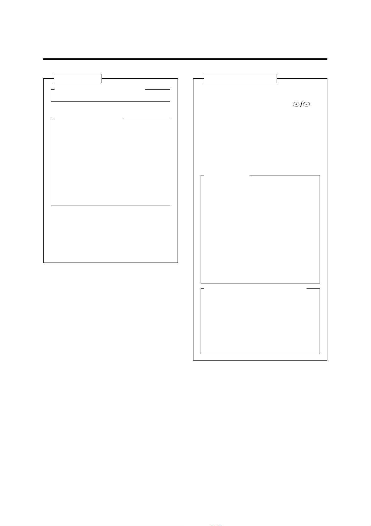
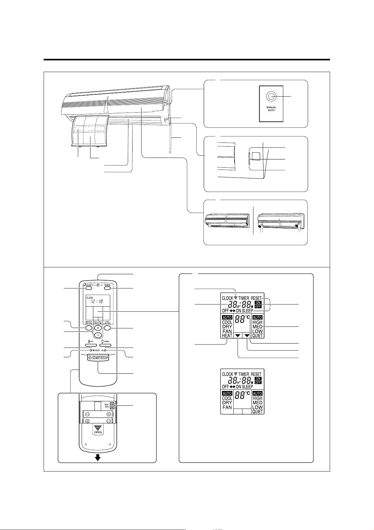
Fig. 1 Indoor Unit
1 Operating Control Panel (Fig. 2)
2 MANUAL AUTO button
3 Remote Control Signal Receiver
4 Indicator Lamps (Fig. 3)
5 OPERATION Indicator Lamp (red)
Lights when unit is operating.
●
*
● The lamp will flash slowly when the de-
frosting operation (see page 17).
● The lamp will flash quickly (1 second on, 1
*
second off) when the selected operating
mode can not be used (see page 18).
6 TIMER Indicator Lamp (green)
●
If the TIMER indicator lamp flashes when
the timer is operating, it indicates that a
fault has occurred with the timer setting
(see page 17 Auto Restart).
7 SWING Indicator Lamp (orange)
8 Intake Grille (Fig. 4)
9 Air Filter
0 Air Flow Direction Louver
A Right-Left Louver
(behind Air Flow Direction Louver)
B Drain Hose
C Air Cleaning Filter
Fig. 5 Remote Control Unit
D SLEEP button
E MASTER CONTROL button
F SET TEMP./SET TIME buttons (
G Signal Transmitter
H TIMER button
I FAN CONTROL button
J START/STOP button
K AIR FLOW DIRECTION button
L SWING LOUVER button
M TIME ADJUST button
N ACL button
Rear side (Fig. 6)
O TEST RUN
● Touch the two metal contacts with a metallic object to send the signal to perform
a test run.
● Perform a test run only when installing the
air conditioner. If the signal to perform a
test run is received during normal operation, the air conditioner’s thermostat will
malfunction.
● If the signal to perform a test run is received during normal operation, the unit
will switch to the test operation mode and
the indoor unit’s OPERATION and TIMER
indicator lamps will flash simultaneously.
● To stop the test operation mode, press the
START/STOP button to stop the air conditioner.
P Remote Control Unit Display (Fig. 7)
Q Transmit Indicator
R Clock Display
S Operating Mode Display
T T imer Mode Display
U Fan Speed Display
V Temperature Set Display
W T imer Set Indicator
X Temperature Set Indicator
)
4
Page 6
PREPARATION
Turn on the Power
Turn on the circuit breaker.
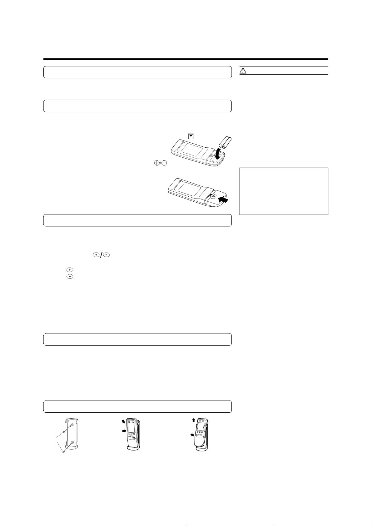
Load Batteries (R03/LR03
Press and slide the battery compartment lid on the re-
1
verse side to open it.
Slide in the direction of the arrow while pressing the mark.
Insert batteries.
2
Be sure to align the battery polarities ( ) correctly.
Close the battery compartment lid.
3
Set the Current time
Press the TIME ADJUST button (Fig. 6 M).
1
Use the tip of a ball-point pen or other small object to press the button.
××
× 2)
××
CAUTION!
● Take care to prevent infants from
accidentally swallowing batteries.
● When not using the remote control unit
for an extended period, remove the
batteries to avoid possible leakage and
damage to the unit.
● If leaking battery fluid comes in contact
with your skin, eyes, or mouth, immediately wash with copious amounts of
water, and consult your physician.
● Dead batteries should be removed
quickly and disposed of properly, either
by placing in a public battery collection
receptacle, or by returning to appropriate authority.
● Do not attempt to recharge dry batteries.
Never mix new and used batteries, or
batteries of different types.
Batteries should last about one year
under normal use. If the remote control
unit’s operating range becomes appreciably reduced, replace the batteries and
press the ACL button with the tip of a
ballpoint pen or other small object.
Use the SET TIME buttons (Fig. 5 F) to adjust
2
the clock to the current time.
button: Press to advance the time.
button: Press to reverse the time.
(Each time the buttons are pressed, the time will be advanced/reversed in
one-minute increments; hold the buttons depressed to change the time
quickly in ten-minute increments.)
Press the TIME ADJUST button again.
3
This completes the time setting and starts the clock.
To Use the Remote Control Unit
● The remote control unit must be pointed at signal receiver (Fig. 1 3) to operate
correctly.
● Operating range: About 7 meters.
● When a signal is properly received by the air conditioner, a beeping sound will
be heard.
● If no beep is heard, press the remote control unit button again.
Remote Control Unit Holder
Insert
Press in
Screws
Slide up
Pull out
1 Mount the Holder. 2 Set the Remote Control
Unit.
5
3 To remove the Remote
Control Unit (when use at
hand).
Page 7

OPERATION
Instructions relating to heating (*) are applicable only to “HEAT & COOL MODEL” (Reverse Cycle).
To Select Mode Operation
Press the START/STOP button (Fig. 5 J).
1
The indoor unit’s OPERATION indicator lamp (red) (Fig. 3 5) will light.
The air conditioner will start operating.
Press the MASTER CONTROL button (Fig. 5 E) to se-
2
lect the desired mode.
Each time the button is pressed, the mode will change in the following
order:
ss
AUTO COOL DRY
t
About three seconds later, the entire display will reappear.
*HEAT FAN
To Set the Thermostat
Press the SET TEMP. buttons (Fig. 5 F).
button: Press to raise the thermostat setting.
button: Press to lower the thermostat setting.
*●Thermostat setting range: HEAT & COOL MODEL (REVERSE CYCLE)
AUTO .................................. 18 to 30 °C
Heating ............................... 16 to 30 °C
The thermostat cannot be used to set room temperature during the FAN mode
(the temperature will not appear on the remote control unit’s display).
●Thermostat setting range: COOLING MODEL
(During use of FAN mode, if the thermostat is set at 17 °C or lower, the display will
show ”--” and the fan will operate continuously, regardless of the room temperature.)
Cooling/Dry ........................ 18 to 30 °C
AUTO .................................. Standard temperature setting ± 2 °C
Cooling/Dry ........................ 18 to 30 °C
FAN ..................................... 17 to 30 °C
s
t
Example: When set to COOL
Example: When set to 26 °C
About three seconds later, the entire display will reappear.
The thermostat setting should be considered a standard value, and may differ
somewhat from the actual room temperature.
To Set the Fan Speed
Press the FAN CONTROL button (Fig. 5 I).
Each time the button is pressed, the fan speed changes in the following order:
AUTO HIGH MED LOW QUIET
About three seconds later, the entire display will reappear.
ssss
s
6
Page 8

OPERATION
Instructions relating to heating (*) are applicable only to “HEAT & COOL MODEL” (Reverse Cycle).
When set to AUTO:
* Heating : Fan operates so as to optimally circulate warmed air.
However, the fan will operate at very low speed when the temperature
of the air issued from the indoor unit is low.
Cooling : As the room temperature approaches that of the thermostat setting,
the fan speed becomes slower.
* Fan: HEAT & COOL MODEL (REVERSE CYCLE)
The fan alternately turns on and off; when on, the fan runs at the low
fan speed.
The fan will operate at very low setting during Monitor operation and
at the start of the Heating mode.
Fan: COOLING MODEL
The fan will operate at the optimum speed in accordance with the
room temperature in the vicinity of the indoor unit.
When set to QUIET:
SUPER QUIET operation begins. The indoor unit’s airflow will be reduced for quieter operation.
● SUPER QUIET operation cannot be used during Dry mode. (The same is true
when dry mode is selected during AUTO mode operation.)
● During Super Quiet operation, *(Heating and) Cooling performance will be reduced somewhat.
To Stop Operation
Example: When set to AUTO
Press the START/STOP button.
The OPERATION indicator lamp (red) (Fig. 3 5) will go out.
About Mode Operation
*AUTO (AUTO CHANGEOVER): HEAT & COOL MODEL (REVERSE CYCLE)
● When AUTO CHANGEOVER operation is selected, the air conditioner selects the
appropriate operation mode (Cooling or Heating) in response to your room’s
temperature.
● When AUTO CHANGEOVER operation first selected, the fan will operate at very
low speed for about one minute, during which time the unit detects the room
conditions and selects the proper operating mode.
● When the air conditioner has adjusted your room’s temperature to near the thermostat setting, it will begin monitor operation. In the monitor operation mode,
the fan will operate at low speed. If the room temperature subsequently changes,
the air conditioner will once again select the appropriate operation (Heating, Cooling) to adjust the temperature to the value set in the thermostat. (The monitor
operation range is ±2 °C relative to the thermostat setting.)
● If the mode automatically selected by the unit is not what you wish, see page 6
and select one of the mode operation (HEAT, COOL, DRY, FAN).
Example: When set to QUIET
7
Page 9

AUTO: COOLING MODEL
● Depending on the room temperature at the time operation begins, the operating
mode will be switched automatically as shown in the accompanying table.
Also, depending on the operating mode, the room temperature setting will cause
the “standard” temperature to be set as shown.
Actual Room Operating Mode Thermostat Setting
Temperature (standard setting)
30 °C or above → Cooling → 27 °C
27 to 30 °C → Cooling → 26 °C
25 to 27 °C → Dry → 24 °C
23 to 25 °C → Dry → 22 °C
Below 23 °C → Dry → 20 °C
The operating mode and standard thermostat settings are selected automatically
when operation begins.
● When automatic operation is initiated, the fan will run at very low speed for about
one minute while the unit detects and selects the proper operating mode.
● Once the operating mode has been set, the mode will not change even if the
room temperature changes.
● If the START/STOP button is pressed to recommence operation within two hours
after stopping automatic operation, the unit will begin operating from the same
mode as before.
*Heating:
● Use to warm your room.
● When Heating mode is selected, the air conditioner will operate at very low fan
speed for about 3 to 5 minutes, after which it will switch to the selected fan setting. This period of time is provided to allow the indoor unit to warm up before
beginning full operation.
● When the room temperature is very low, frost may form on the outside unit, and
its performance may be reduced. In order to remove such frost, the unit will
automatically enter the defrost cycle from time to time. During Automatic Defrosting operation, the OPERATION indicator lamp (red) will flash, and the heat
operation will be interrupted.
Cooling:
● Use to cool your room.
Dry:
● Use for gently cooling while dehumidifying your room.
● You cannot heat the room during Dry mode.
● During Dry mode, the unit will operate at low speed; in order to adjust room
humidity, the indoor unit’s fan may stop from time to time. Also, the fan may
operate at very low speed when detecting room humidity.
● The fan speed cannot be changed manually when Dry mode has been selected.
Fan:
● Use to circulate the air throughout your room.
* During Heating mode:
Set the thermostat to a temperature setting that is higher than the current room
temperature. The Heating mode will not
operate if the thermostat is set lower than
the actual room temperature.
During Cooling/Dry mode:
Set the thermostat to a temperature setting that is lower than the current room
temperature. The Cooling and Dry modes
will not operate if the thermostat is set
higher than the actual room temperature
(in Cooling mode, the fan alone will operate).
* During Fan mode:
HEAT & COOL MODEL (REVERSE CYCLE)
You can not use the unit to heat and cool
your room.
During Fan mode: COOLING MODEL
● Fan operation begins when room temperature in the vicinity of the air conditioner rises above the set thermostat
temperature; when the temperature
drops, fan operation stops.
● If the air emitted feels too cool, raise
the thermostat setting.
8
Page 10

TIMER OPERATION
Before using the timer function, be sure that the Remote Control Unit is set to the correct current time (see page 5).
To Use the ON timer or OFF timer
Press the START/STOP button (Fig. 5 J)
1
(if the unit is already operating, proceed to step 2).
The indoor unit’s OPERATION indicator lamp (red) (Fig. 3 5) will light.
Press the TIMER button (Fig. 5 H) to select the OFF
2
timer or ON timer operation.
Each time the button is pressed the timer function changes in the following order:
RESET OFF ON
PROGRAM(OFF → ON, OFF ← ON)
The indoor unit’s TIMER indicator lamp (green) (Fig. 3 6) will light.
sss
t
Use the SET TIME buttons (Fig. 5 F) to adjust the de-
3
sired OFF time or ON time.
Set the time while the time display is flashing (the flashing will continue
for about five seconds).
button: Press to advance the time.
button: Press to reverse the time.
To Cancel the Timer
Use the TIMER button to select “TIMER
RESET”.
The air conditioner will return to normal
operation.
To Change the Timer Settings
Perform steps 2 and 3.
To Stop Air Conditioner Operation
while the Timer is Operating
Press the START/STOP button.
To Change Operating Conditions
If you wish to change the operating
conditions (Mode, Fan Speed, Thermostat
Setting), after making the timer setting,
wait until the entire display reappears, then
press the appropriate buttons to change
the operating condition desired.
About five seconds later, the entire display will reappear.
To Use the PROGRAM timer
Press the START/STOP button (Fig. 5 J)
1
(if the unit is already operating, proceed to step 2).
The indoor unit’s OPERATION indicator lamp (red) (Fig. 3 5) will light.
Set the desired times for OFF timer and ON timer.
2
See the section “To Use the ON timer or OFF timer” to set the desired
mode and times.
About three seconds later, the entire display will reappear.
The indoor unit’s TIMER indicator lamp (green) (Fig. 3 6) will light.
Press the TIMER button (Fig. 5 H) to select the PRO-
3
GRAM timer operation (either OFF → ON or OFF ← ON
will display).
The display will alternately show “OFF timer” and “ON timer”, then change
to show the time setting for the operation to occur first.
● The PROGRAM timer will begin operation. (If the ON timer has been
selected to operate first, the unit will stop operating at this point.)
About five seconds later, the entire display will reappear.
About the PROGRAM timer
● The PROGRAM timer allows you to integrate OFF timer and ON timer operations
in a single sequence. The sequence can involve one transition from OFF timer to
ON timer, or from ON timer to OFF timer, within a twenty-four hour period.
● The first timer function to operate will be the one set nearest to the current time.
The order of operation is indicated by the arrow in the Remote Control Unit’s
display (OFF → ON, or OFF ← ON).
● One example of PROGRAM timer use might be to have the air conditioner automatically stop (OFF timer) after you go to sleep, then start (ON timer) automatically in the morning before you arise.
To Cancel the Timer
Use the TIMER button to select “TIMER
RESET”.
The air conditioner will return to normal
operation.
To Change the Timer Settings
Follow the instructions given in the section
1.
“To Use the ON Timer or OFF Timer” to select the timer setting you wish to change.
2. Press the TIMER button to select either
OFF → ON or OFF ← ON.
To Stop Air Conditioner Operation
while the Timer is Operating
Press the START/STOP button.
To Change Operating Conditions
If you wish to change operating conditions
(Mode, Fan Speed, Thermostat Setting),
after making the timer setting wait until the
entire display reappears, then press the
appropriate buttons to change the operating condition desired.
9
Page 11

SLEEP TIMER OPERATION
Instructions relating to heating (*) are applicable only to “HEAT & COOL MODEL” (Reverse Cycle).
Unlike other timer functions, the SLEEP timer is used to set the length of time until air conditioner operate is stopped.
To Use the SLEEP timer
While the air conditioner is operating or stopped, press the
SLEEP button (Fig. 5 D).
Both the indoor unit’s OPERATION indicator lamp (red) (Fig. 3 5) and the TIMER
indicator lamp (green) (Fig. 3 6) will light.
To Change the Timer Settings
Press the SLEEP button (Fig. 5 D) once again and set the time
using the SET TIME buttons (Fig. 5 F).
Set the time while the Timer Mode Display is flashing (the flashing will continue for
about five seconds).
button: Press to advance the time.
button: Press to reverse the time.
About five seconds later, the entire display will reappear.
About the SLEEP timer
To prevent excessive warming or cooling during sleep, the SLEEP timer function automatically modifies the thermostat setting in accordance with the time setting. When the set time has elapsed, the air conditioner completely stops.
To Cancel the Timer:
Use the TIMER button to select “TIMER
RESET”.
The air conditioner will return to normal
operation.
To Stop the Air Conditioner During
Timer Operation:
Press the START/STOP button.
*During Heating operation:
When the SLEEP timer is set, the thermostat setting is
automatically lowered 1 °C every thirty minutes. When the
thermostat has been lowered a total of 4 °C, the thermostat
setting at that time is maintained until the set time has elapsed,
at which time the air conditioner automatically turns off.
SLEEP timer setting
1 °C
2 °C
3 °C
30
minutes
1 hour
1 hour
30 minutes
Set time
4 °C
During Cooling/Dry operation:
When the SLEEP timer is set, the thermostat setting is automatically raised 1 °C every sixty minutes. When the thermostat has been raised a total of 2 °C, the thermostat setting at
that time is maintained until the set time has elapsed, at which
time the air conditioner automatically turns off.
SLEEP timer setting
Set time
1 hour
1 °C
2 °C
10
Page 12

ADJUSTING THE DIRECTION OF AIR CIRCULATION
Instructions relating to heating (*) are applicable only to “HEAT & COOL MODEL” (Reverse Cycle).
Vertical (up-down) direction of airflow is adjusted by pressing the Remote Control Unit’s AIR FLOW DIRECTION button. Horizontal (right-left) airflow direction is adjusted manually, by moving the Air Flow Direction Louvers.
Whenever making horizontal airflow adjustments, start air conditioner operation and be sure that the vertical air direction
louvers are stopped.
Vertical Air Direction Adjustment
Press the AIR FLOW DIRECTION button (Fig. 5 K).
Each time the button is pressed, the air direction range will change as follows:
2 1 6 5 4
3
Types of Air flow Direction Setting:
1, 2, 3 : During Cooling/Dry modes
4, 5, 6 : During Heating mode
The remote Control Unit’s display does
not change.
● Use the air direction adjustments within the ranges shown above.
● The vertical airflow direction is set automatically as shown, in accordance with
the type of operation selected.
During Cooling/Dry modes : Horizontal flow 1
* During Heating mode : Downward flow 5
● During AUTO mode operation, for the first minute after beginning operation,
airflow will be horizontal 1; the air direction cannot be adjusted during this period.
1
2
3
4
5
6
DANGER!
Never place fingers or foreign objects inside
the outlet ports, since the internal fan operates at high speed and could cause personal
injury.
● Always use the remote control unit’s
AIR FLOW DIRECTION button to adjust
the vertical airflow louvers. Attempting
to move them manually could result in
improper operation; in this case, stop
operation and restart. The louvers
should begin to operate properly again.
● During use of the Cooling and Dry
modes, do not set the Air Flow Direction Louvers in the Heating range (4 -
6) for long periods of time, since water vapor may condense near the outlet louvers and drops of water may drip
from the air conditioner. During the
Cooling and Dry modes, if the Air Flow
Direction Louvers are left in the heating range for more than 30 minutes,
they will automatically return to position 3.
● When used in a room with infants, children, elderly or sick persons, the air
direction and room temperature
should be considered carefully when
making settings.
Right-Left Adjustment
Adjust the Right-Left louvers.
● Move the Right-Left louvers to adjust air flow in the direction you prefer.
Right-Left Louvers
knob
11
Page 13

SWING OPERATION
Begin air conditioner operation before performing this procedure.
To select SWING Operation
Press the SWING LOUVER button (Fig. 5 L).
The SWING indicator lamp (orange) (Fig. 3 7) will light.
In this mode, the Air Flow Direction Louvers will swing automatically to direct the
airflow both up and down.
To Stop SWING Operation
Press the SWING LOUVER button (Fig. 5 L) once again.
The SWING indicator lamp (orange) (Fig. 3 7) will go out.
Airflow direction will return to the setting before swing was begun.
About Swing Operation
● The range of swing is relative to the currently set airflow
direction.
● If the swing range is not as desired, use the Remote Control Unit’s AIR FLOW DIRECTION button to change the
range of swing.
● During Cooling/Dry modes, if SWING Operation is continued at the lowest (downward) range for more than 30
minutes, the unit will automatically switch the swing range
to the horizontal flow range to prevent the condensation
of moisture on the outlet.
● The SWING operation may stop temporarily when the air
conditioner’s fan is not operating, or when operating at
very low speeds.
MANUAL AUTO OPERATION
Use the MANUAL AUTO operation in the event the Remote Control Unit is lost or otherwise unavailable.
How To Use the Main Unit Controls
Press the MANUAL AUTO button (Fig. 2 2) on the main unit
control panel.
To stop operation, press the MANUAL AUTO button once again.
(Controls are located inside the intake grille.)
● When the air conditioner is operated
with the controls on the Main unit, it
will operate under the same mode as
the AUTO mode selected on the Remote Control Unit (see page 7).
● The fan speed selected will be “AUTO”
and the thermostat setting will be
standard.
12
Page 14

CLEANING AND CARE
CAUTION!
● Before cleaning the air conditioner, be sure to turn it off and disconnect the power supply cord.
● Be sure the intake grille (Fig. 1 8) is installed securely.
● When removing and replacing the air filters, be sure not to touch the heat exchanger, as personal
injury may result.
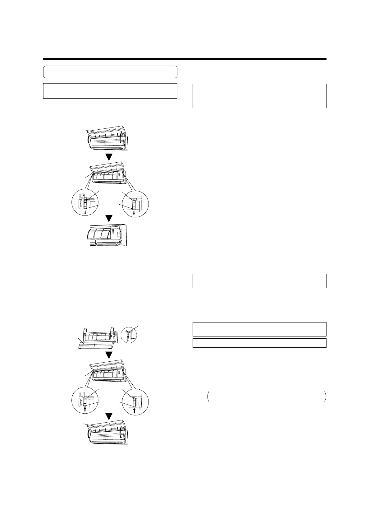
Cleaning the Intake Grille
1. Remove the intake grille.
1 Place your fingers at both lower ends of the grille
panel, and lift forward; if the grille seems to catch
partway through its movement, continue lifting upward to remove.
2 Pull past the intermediate catch and open the Intake
Grille wide so that it become horizontal.
Intake Grille
2
1
2
1
Intake Grille
Mounting
shaft
Knob
2. Clean with water.
Remove dust with a vacuum cleaner; wipe the unit with
warm water, then dry with a clean, soft cloth.
Cleaning the Air Filter
1. Open the intake grille, and remove the air
filter.
Lift up the air filter’s handle, disconnect the two lower
tabs, and pull out.
Air filter handle
Hooks (two places)
2. Remove dust with a vacuum cleaner or by
washing.
After washing, allow to dry thoroughly in a shaded place.
3. Replace the air filter and close the intake
grille.
1 Align the sides of the air filter with the panel, and push
in fully, making sure the two lower tabs are returned
properly to their holes in the panel.
3. Replace the intake grille.
1 Pull the knobs all the way.
2 Hold the grille horizontal and set the left and right
mounting shafts into the bearings at the top of the
panel.
Mounting shaft
2
Intake Grille
Intake Grille
Bearing
1
Knob
Mounting
shaft
Knob
Hooks (two places)
2 Close the intake grille.
(For purposes of example, the illustration shows the unit
without intake grille installed.)
● Dust can be cleaned from the air filter either with a vacuum
cleaner, or by washing the filter in a solution of mild detergent and warm water. If you wash the filter, be sure to
allow it to dry thoroughly in a shady place before reinstalling.
● If dirt is allowed to accumulate on the air filter, air flow
will be reduced, lowering operating efficiency and increasing noise.
● During periods of normal use, the air filters should be
cleaned every two weeks.
13
Page 15

Air Cleaning Filter Installation
1. Open the intake grille and remove the air
filters.
Intake Grille
2
1
Intake Grille
2
1
Mounting
shaft
Knob
2. Install the air cleaning filter set (set of 2).
1 Set the air cleaning filter into the air cleaning filter
frame.
Air cleaning filter set
Air cleaning filter frame
3. Install the two air filters and close the
intake grille.
Mounting shaft
2
Bearing
shaft
Knob
1
Knob
1
2
Intake Grille
Intake Grille
Mounting
Intake Grille
1
2
● When air cleaning filters are used, the effect will increased
by setting the fan speed to “High”.
Air cleaning filter
2 Engage the latch at both ends of the filter with the two
hooks at the rear of the air cleaning filter frame.
Hooks (two places at the rear)
Latches (two places)
Take care that the air cleaning filter does not project beyond the frame.
3 Engage the four fixing locations at the top and bot-
tom of the air cleaning filter frame with the hooks of
the air filter.
Rear of the filter
Fixing location, hooks (four places)
14
Page 16
CLEANING AND CARE
Replacing dirty Air cleaning filters
Please purchase the separately sold replacement air cleaning filters and install them.
1. Open the intake grille and remove the air
filters.
Intake Grille
2
1
Intake Grille
2
1
Mounting
shaft
Knob
2. Replace them by two new air cleaning
filters.
1 Remove the old air cleaning filters in reverse order of
their installation.
2 Install in the same way as for installation of the air
cleaning filter set.
3. Install the two air filters and close the
intake grille.
Mounting shaft
Intake Grille
Intake Grille
Intake Grille
2
Mounting
shaft
Knob
1
2
1
Bearing
1
Knob
2
In regard to the Air cleaning filters
(The air cleaning filter type differs depending
on the model.)
[AIR-PURIFYING FILTER (green filter)]
● Depending on the size of the room and the conditions in
which the air conditioner is used, the normal life of the
air-purifying filter is about three months. If the air-purifying filter becomes dirty within three months, replace it as
soon as possible. (Always dispose of used air-purifying
filters, do not reuse them.)
[DEODORIZING FILTER (black filter)]
● To regenerate the deodorizing effect, remove the dust with
a vacuum cleaner and place the filter in direct sunlight
for six hours about once every six months. Under normal
conditions, the filter should be replaced after three years.
● For storage of the air cleaning filters, avoid places with
high temperatures and high humidity, and use the filters
as soon as possible after the package has been opened.
(The air cleaning effect decreases when the filters are left
in the opened package.)
[POLYPHENOL CATECHIN AIR CLEANING FILTER (white filter)]
● The Air Cleaning Filters are disposable filters. (They can
not be washed and reused.)
● For storage of the Air Cleaning Filters, use the filters as
soon as possible after the package has been opened.
(The air cleaning effect decreases when the filters are left
in the opened package)
● Generally, the filters should be exchanged about every
three months.
Please buy delicated air cleaning filters (UTR-FC04-1) (Sold
separately) to exchange the used dirty air cleaning filters.
[NEGATIVE AIR IONS DEODORIZING FILTER (light green
filter)]
● The filters should be exchanged about every three years
so as to maintain the deodorizing effect.
● Filter frame is not a one-off product.
Please buy delicated deodorizing filter (UTR-FC04-3) (Sold
separately) when exchanging the filters.
Maintenance of Deodorizing Filters
In order to maintain the deodorizing effect, please clean the
filter in the follow way once three months.
1 Remove the deodorizing filter.
2 Clean with water and dry in the air.
1) Flush the filters with high-pressure hot water until
the surface of the filters are covered with water.
Please flush with diluent neutral detergent.
Never wash by reaming or rubbing, otherwise it
will damage the deodorizing effect.
2) Rinse with water flow.
3) Dry in shade.
3 Reinstall the deodorizing filter.
15
Page 17
TROUBLESHOOTING
Instructions relating to heating (*) are applicable only to “HEAT & COOL MODEL” (Reverse Cycle).
WARNING!
Before requesting service, perform the following checks:
In the event of a malfunction (burning smell, etc.), immediately stop operation, disconnect the
Power Supply Plug or turn off the circuit breaker, and consult authorized service personnel.
Merely turning off the unit’s power switch will not completely disconnect the unit from the power
source. Always be sure to turn off your circuit breaker to ensure that power is completely off.
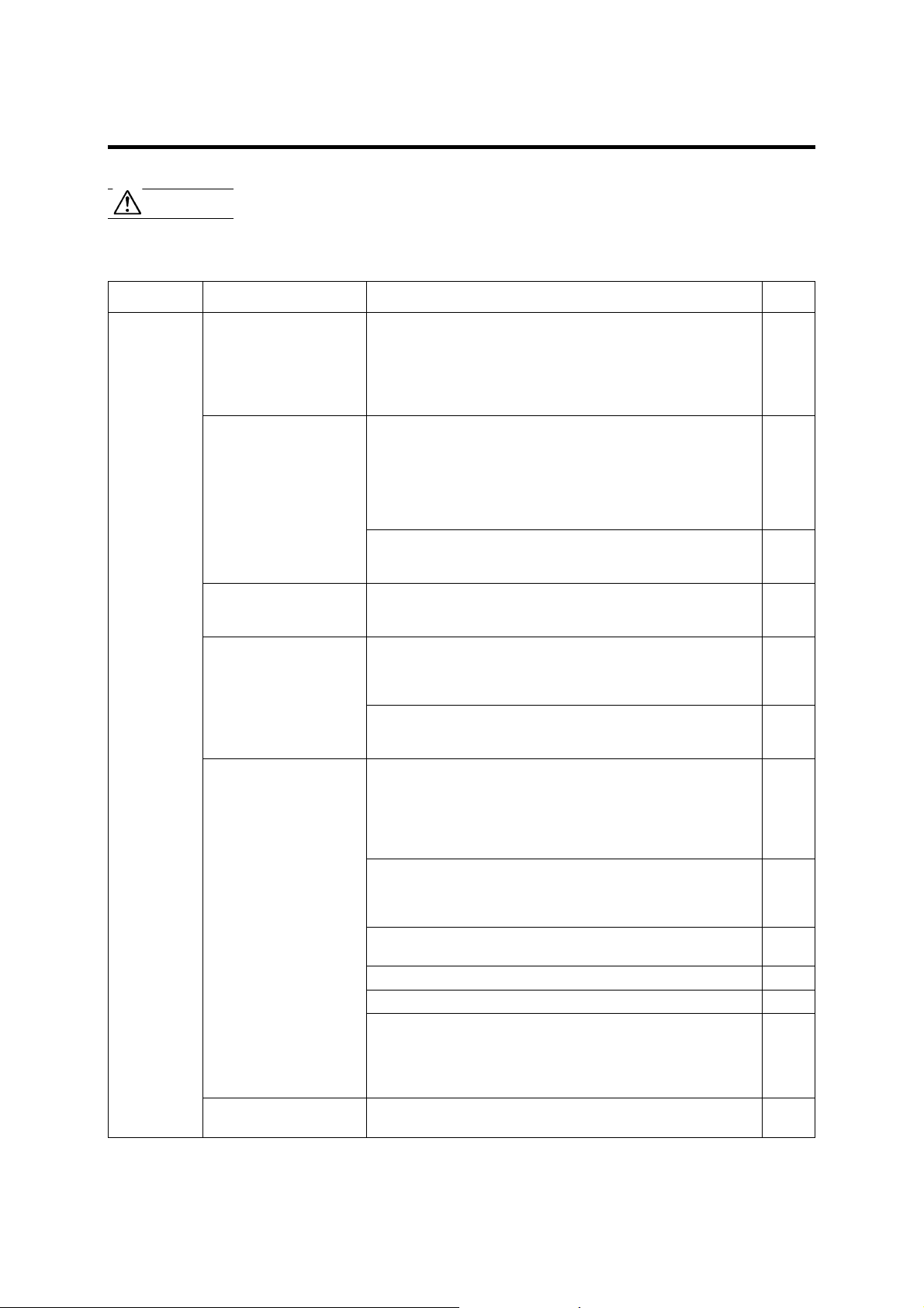
NORMAL
FUNCTION
Symptom
Doesn’t operate immediately:
Noise is heard:
Smells:
Mist or steam are
emitted:
Airflow is weak or stops:
Water is produced from
the outdoor unit:
Problem
● If the unit is stopped and then immediately started again, the compressor will not operate for about 3 minutes, in order to prevent
fuse blowouts.
● Whenever the power supply plug is disconnected and then reconnected to a power outlet, the protection circuit will operate for about
3 minutes, preventing unit operation during that period.
● During operation and immediately after stopping the unit, the
sound of water flowing in the air conditioner’s piping may be
heard. Also, noise may be particularly noticeable for about 2 to 3
minutes after starting operation (sound of coolant flowing).
● During operation, a slight squeaking sound may be heard. This is
the result of minute expansion and contraction of the front cover
due to temperature changes.
*● During Heating operation, a sizzling sound may be heard occa-
sionally. This sound is produced by the Automatic Defrosting operation.
● Some smell may be emitted from the indoor unit. This smell is
the result of room smells (furniture, tobacco, etc.) which have
been taken into the air conditioner.
● During Cooling or Dry operation, a thin mist may be seen emitted
from the indoor unit. This results from the sudden Cooling of
room air by the air emitted from the air conditioner, resulting in
condensation and misting.
*● During Heating operation, the outdoor unit’s fan may stop, and
steam may be seen rising from the unit. This is due to the Automatic Defrosting operation.
*● When Heating operation is started, fan speed is temporarily very
low, to allow internal parts to warm up.
*● During Heating operation, if the room temperature rises above
the thermostat setting, the outdoor unit will stop, and the indoor
unit will operate at very low fan speed. If you wish to warm the
room further, set the thermostat to a higher setting.
*● During Heating operation, the unit will temporarily stop opera-
tion (between 7 and 15 minutes) as the Automatic Defrosting mode
operates. During the Automatic Defrosting operation, the OPERATION indicator lamp will flash.
● The fan may operate at very low speed during Dry operation or
when the unit is monitoring the room’s temperature.
● During SUPER QUIET operation, the fan will operate at very low speed.
● In the monitor AUTO operation, the fan will operate at very low speed.
*● In case of Multi-type unit, if multiple units are operated in different
operation modes as shown below, the units operated afterward will
stop and the OPERATION indicator lamp (red) will flash.
Heating mode and cooling mode (or dry mode)
Heating mode and fan mode
*● During Heating operation, water may be produced from the out-
door unit due to the Automatic Defrosting operation.
See page
—
—
17
—
—
17
—
17
7
7
7
18
17
16
Page 18

TROUBLESHOOTING
Symptom
CHECK ONCE
MORE
If the problem persists after performing these checks, or if you notice burning smells, or the TIMER indicator Lamp (Fig. 3 6)
flashes, immediately stop operation, turn off the circuit breaker, and consult authorized service personnel.
Doesn’t operate at all:
Poor Cooling (or *Heating)
performance:
The unit operates
differently from the
remote control unit’s
setting:
● Has the circuit breaker been turn off?
● Has there been a power failure?
● Has a fuse blown out, or a circuit breaker been tripped?
● Is the timer operating?
● Is the air filter dirty?
● Are the air conditioner’s intake grille or outlet port blocked?
● Did you adjust the room temperature settings (thermostat) cor-
rectly?
● Is there a window or door open?
● In the case of Cooling operation, is a window allowing bright sun-
light to enter? (Close the curtains.)
● In the case of Cooling operation, are there heating apparatus and
computers inside the room, or are there too many people in the
room?
● Is the unit set for SUPER QUIET operation?
● Are the Remote Control Unit’s batteries dead?
● Are the Remote Control Unit’s batteries loaded properly?
Items to check
See page
—
9
—
7
5
OPERATING TIPS
Instructions relating to heating (*) are applicable only to “HEAT & COOL MODEL” (Reverse Cycle).
Operation and Performance
*Heating Performance
● This air conditioner operates on the heat-pump principle,
absorbing heat from outdoor air and transferring that heat
indoors. As a result, the operating performance is reduced
as outdoor air temperature drops. If you feel that insufficient heating performance is being produced, we recommend you use this air conditioner in conjunction with
another kind of heating appliance.
● Heat-pump air conditioners heat your entire room by
recirculating air throughout the room, with the result that
some time may be required after first starting the air conditioner until the room is heated.
*
When Indoor and Outdoor Temperatures are High
When both indoor and outdoor temperatures are high during use of the heating mode, the outdoor unit’s fan may stop
at times.
*Microcomputer-controlled Automatic Defrosting
● When using the Heating mode under conditions of low
outdoor air temperature high humidity, frost may form
on the outdoor unit, resulting in reduced operating performance.
In order to prevent this kind of reduced performance, this
unit is equipped with a Microcomputer-controlled Automatic Defrosting function. If frost forms, the air conditioner will temporarily stop, and the defrosting circuit will
operate briefly (for about 7 to 15 minutes).
During Automatic Defrosting operation, the OPERATION
indicator lamp (red) will flash slowly.
AUTO Restart
In Event of Power Interruption
● The air conditioner power has been interrupted by a
power failure. The air conditioner will then restart automatically in its previous mode when the power is restored.
● Operated by setting before the power failure.
● If a power failure occurs during TIMER operation, the timer
will be reset and the unit will begin (or stop) operation at
the new time setting. In the event that this kind of timer
fault occurs the TIMER Indicator Lamp (green) will flash
(see page 4).
● Use of other electrical appliances (electric shaver, etc.) or
nearby use of a wireless radio transmitter may cause the
air conditioner to malfunction. In this event, temporarily
disconnect the Power Supply Plug, reconnect it, and then
use the remote control unit to resume operation.
17
Page 19

OPERATING TIPS
Multi-type Air conditioner
This indoor unit can be connected to a multi-type outdoor unit. The multi-type air conditioner allows multiple indoor units to
be operated in multiple locations. The indoor units may be operated simultaneously, in accordance with their respective
output.
Simultaneous Use of Multiple Units
Instructions relating to inverter (
● When using a multi-type air conditioner, the multiple
indoor units can be operated simultaneously, but when
two or more indoor units of the same group are operated simultaneously, the heating and cooling efficiency
will be less than when a single indoor unit is used alone.
Accordingly, when you wish to use more than one indoor unit for cooling at the same time, the use should
be concentrated at night and other times when less output is required. In the same way, when multiple units
are used simultaneously for heating, it is recommended
that they be used in conjunction with other auxiliary
space heaters, as required.
● Seasonal and outdoor temperature conditions, the structure of the rooms and the number of persons present
may also result in differences of operating efficiency.
We recommend that you try various operating patterns
in order to confirm the level of heating and cooling output provided by your units, and use the units in the way
that best matches your family's lifestyle.
● If you discover that one or more units delivers a low
level of cooling or heating during simultaneous operation, we recommend that you stop simultaneous operation of the multiple units.
❖
● Operation cannot be done in the following different op-
erating modes.
If the indoor unit is instructed to do an operating mode
that it cannot perform, the OPERATION indicator lamp
(red) on the indoor unit will flash (1 second on, 1 second off) and the unit will go into the standby mode.
Heating mode and cooling mode (or dry mode)
Heating mode and fan mode
❖
) are applicable only to “INVERTER MODEL”.
❖
● Operation can be done in the following different operat-
ing modes.
Cooling mode and dry mode
Cooling mode and fan mode
Dry mode and fan mode
❖
● The operating mode (heating mode or cooling (dry)
mode) of the outdoor unit will be determined by the operating mode of the indoor unit that was operated first.
If the indoor unit was started in fan mode, the operating
mode of the outdoor unit will not be determined.
For example, if indoor unit (A) was started in fan mode
and then indoor unit (B) was then operated in heating
mode, indoor unit (A) would temporarily start operation in fan mode but when indoor unit (B) started operating in heating mode, the OPERATION indicator lamp
(red) for indoor unit (A) would begin to flash (1 second
on, 1 second off) and it would go into standby mode.
Indoor unit (B) would continue to operate in heating
mode.
Notice
Instructions relating to heating (*) are applicable only to “HEAT & COOL MODEL” (Reverse Cycle).
*● During use of the heating mode, the outdoor unit will
occasionally commence the defrost operation for brief
periods. During the defrosting operation, if the user sets
the indoor unit for heating again, the defrosting mode
will continue, and the heating operation will begin after
completion of defrosting, with the result that some time
may be required before warm air is emitted.
*● During use of the heating mode, the top of the indoor
unit may become warm, but this is due to the fact that
coolant is circulated through the indoor unit even when
it is stopped; it is not a malfunction.
18
Page 20

OPERATING TIPS
Instructions relating to heating (*) are applicable only to “HEAT & COOL MODEL” (Reverse Cycle).
Temperature and Humidity Range
Permissible ranges of temperature and humidity are as follows:
Outdoor
Temperature
Temperature
Indoor
Humidity
COOLING OPERATION
*HEATING OPERATION
● Acoustic Noise Information: The maximum sound pressure level is less than 70 dB (A) for both indoor unit and outdoor
● If the air conditioner is operated under higher temperature conditions than those listed, the built-in protection circuit may
operate to prevent internal circuit damage. Also, during Cooling and Dry modes, if the unit is used under conditions of
lower temperatures than those listed above, the heat-exchanger may freeze, leading to water leakage and other damage.
● Do not use this unit for any purposes other than the Cooling, (
ordinary dwellings.
● When the outdoor temperature drops, the outdoor unit’s fans may switch to Low Speed.
● If the unit is used for long periods under high-humidity conditions, condensation may form on the surface of the indoor
unit, and drip onto the floor or other objects underneath. (About 80% or more)
About 0 to 46 °C
About –10 to 24 °C
unit. According to IEC 704-1 and ISO 3744.
About 18 to 32 °C
About 30 °C or less
)Heating, Dehumidifying, and air-circulation of rooms in
*
About 80 % or less
If the unit is used for long periods under high-humidity conditions, condensation may form
on the surface of the indoor
unit, and drip onto the floor or
other objects underneath.
19
 Loading...