

Page 1
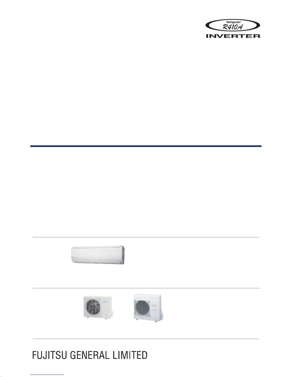
AIR CONDITIONER
Wall Mounted type
INDOOR
OUTDOOR
ASG18LFCA
ASG24LFCC
ASG30LFCA
AOG18LFC
AOG24LFCC
AOG30LFT
DESIGN & TECHNICAL MANUAL
Page 2

1. INDOOR UNIT
WALL MOUNTED TYPE :
ASG18LFCA
ASG24LFCC
ASG30LFCA
DTR_AS075E_04
2016.04.22
Page 3

WALL MOUNTED TYPE
AS
G18-30LFC(C)A
WALL MOUNTED TYPE
AS
G18-30LFC(C)A
CONTENTS
1. INDOOR UNIT
1. FEATURES
.............................................................................................................. 01 - 01
2. WIRELESS REMOTE CONTROLLER
............................................... 01 - 04
3. SPECIFICATIONS
..............................................................................................01 - 06
4. DIMENSIONS
........................................................................................................01 - 08
5. WIRING DIAGRAMS
........................................................................................01 - 10
6. CAPACITY TABLE
.............................................................................................01 - 11
6-1. COOLING CAPACITY
.......................................................................................01 - 11
6-2. HEATING CAPACITY
.......................................................................................01 - 12
7. FAN PERFORMANCE
.................................................................................... 01 - 13
7-1. AIR VELOCITY DISTRIBUTION
..................................................................... 01 - 13
7-2. AIRFLOW
........................................................................................................... 01 - 15
8. OPERATION NOISE (SOUND PRESSURE)
................................. 01 - 18
8-1. NOISE LEVEL CURVE
....................................................................................01 - 18
8-2. SOUND LEVEL CHECK POINT
..................................................................... 01 - 20
9. ELECTRICAL CHARACTERISTICS
................................................... 01 - 21
10. SAFETY DEVICES
............................................................................................ 01 - 22
11. EXTERNAL INPUT & OUTPUT
............................................................... 01 - 23
11-1. EXTERNAL INPUT
...........................................................................................01 - 23
11-2. EXTERNAL OUTPUT
.......................................................................................01 - 25
12. FUNCTION SETTINGS
.................................................................................. 01 - 26
12-1. INDOOR UNIT (Setting by remote controller)
...........................................01 - 26
13. OPTIONAL PARTS
...........................................................................................01 - 30
13-1. CONTROLLERS
............................................................................................... 01 - 30
13-2. OTHERS
............................................................................................................. 01 - 30
Page 4
- (01 - 01) -
WALL MOUNTED TYPE
AS
G18-30LFC(C)A
WALL MOUNTED TYPE
AS
G18-30LFC(C)A
FEATURES1.
MODEL
AS
G18LFCA
AS
G24LFCC
AS
G30LFCA
FEATURES
Energy efciency class
z
MODEL
ASG18LFCA ASG24LFCC ASG30LFCA
Cooling A++ A++ A+
Heating A A A
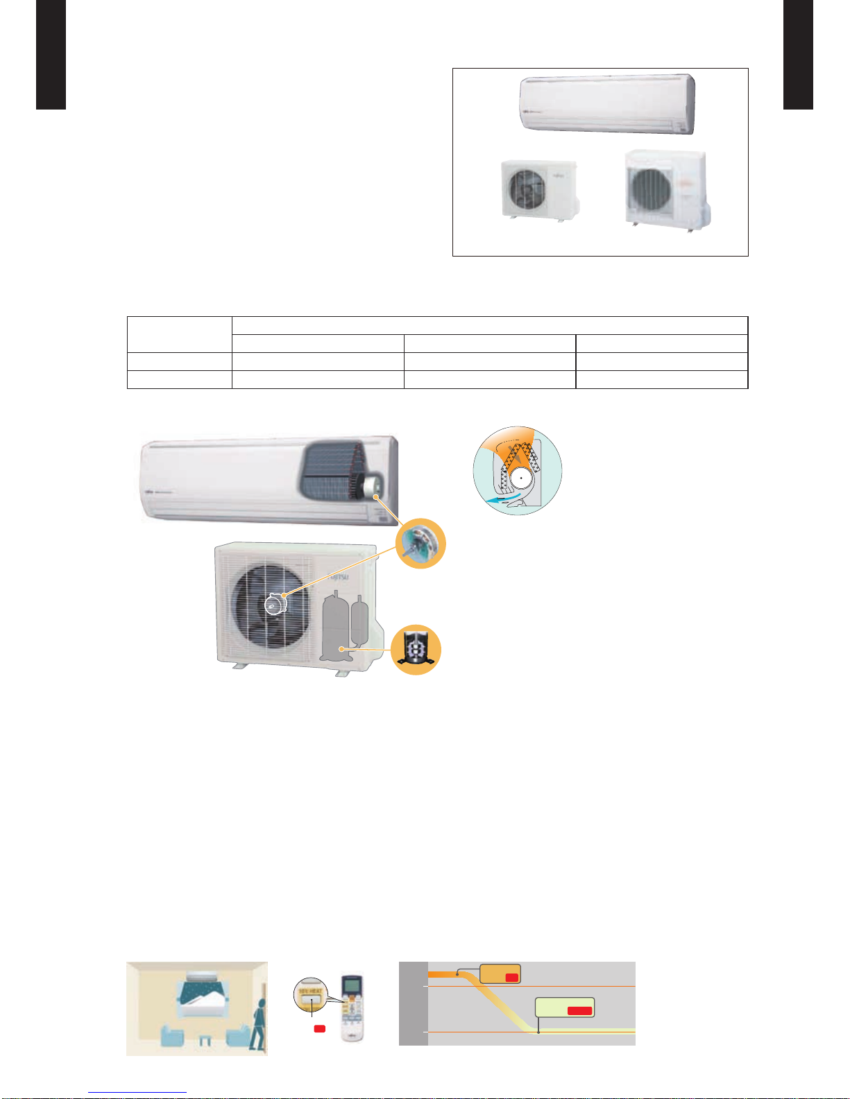
All DC
z
Large airflow and
quiet operation by
new airflow path
High efficiency
layout
DC fan motor
DC compressor
Super quiet
z
Airow mode can be set in 4 steps and more detailed airow setting is possible.
Easy maintenance
z
Easy maintenance and always clean. Troublesome maintenance has been made easy.
Since the front panel is easy to remove, maintenance is also easy.
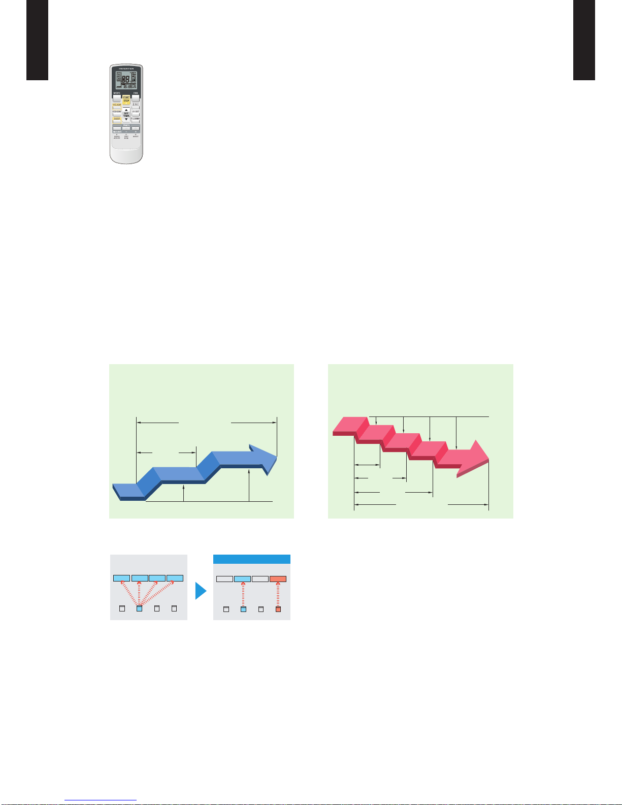
10°C HEAT Operation
z
The room temperature can be set to go no lower than 10 °C,
thus ensuring that the room does not get too cold when not occupied
Caution)
When the room temperature is higher than 10 °C, “10°C HEAT” operation will not start. Operation starts and maintains the room •
temperature at 10 °C when the temperature drops below 10 °C.
10
°C
20
°C
“10°C HEAT”
Button ON
Indoor unit
operation START
“10°C HEAT”
Button ON
AO
G18LFC
AOG24LFCC
AO
G30LFT
Page 5
- (01 - 02) -
WALL MOUNTED TYPE
AS
G18-30LFC(C)A
WALL MOUNTED TYPE
AS
G18-30LFC(C)A
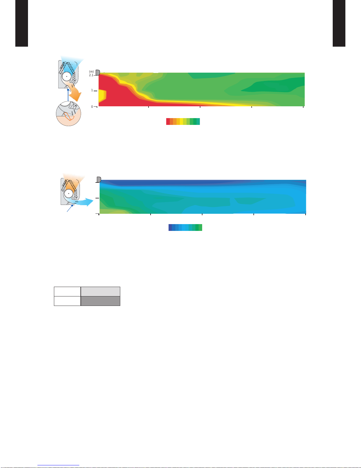
Power diffuser
z
Adoption of large power diffuser
16
Outside air conditions: 2
o
C
o
C
60%
( C)
Operation contents
Operating mode: Heating
Set temperature (Max. set temp): 30
o
2933 32 31 30
Airflow : Hi
Vertical airflow direction louver: Downward
Horizontal airflow direction louver: Center
2.1
1
0
3 6 9 12
(m)
(m)
Power diffuser
(full open)
46
o
“Strong vertical airow” provides powerful
oor level heating.
“Healthy horizontal airow” does not blow cool air
directly at the occupants in the room.
Outside air conditions: 35 oC 40%
( C)
Operation contents
Operating mode: Cooling
Set temperature (Min. set temp):
o
18oC
1815 16 17
2.1
1
0
3 6 9 12
(m)
(m)
Vertical airflow direction louver: Upward
Horizontal airflow direction louver: Center
Power diffuser
Low outdoor air temperature cooling and heating correspondence
z
Corresponds to cooling operation at -10 °C and heating operation at -15 °C outdoor air
temperature
Cooling
-10 °C
Heating
-15 °C
Corresponds to maximum 50m-long piping (30 type)
z
Page 6
- (01 - 03) -
WALL MOUNTED TYPE
AS
G18-30LFC(C)A
WALL MOUNTED TYPE
AS
G18-30LFC(C)A
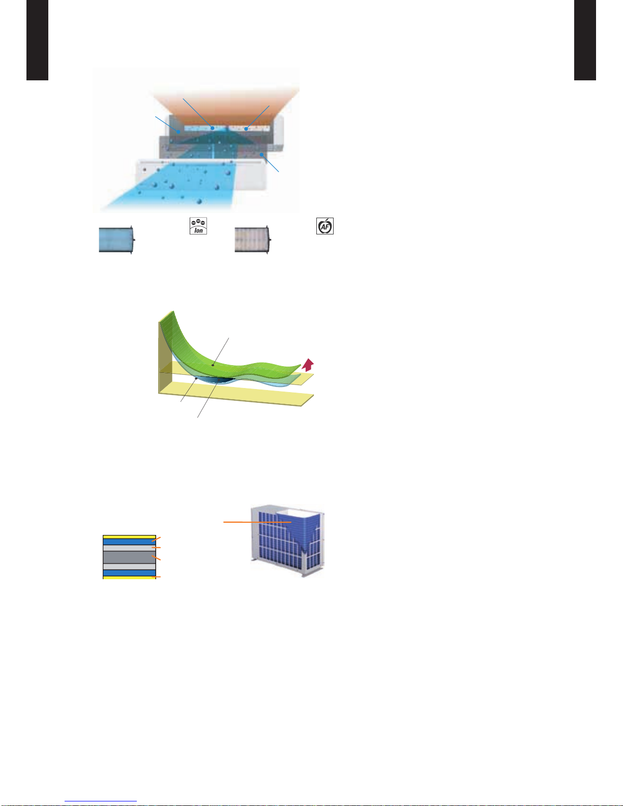
Air conditioner lter features
z
Organic coating fin used
heat exchanger
Air Filter
Ion Deodorization Filter
Apple-catechin Filter
Apple-catechin Filter
Ion Deodorization Filter
Economy operation
z
Example: Cooling operation
Economy operation is energy saving, as ●
the set temperature of indoor unit is shifted
by 1 °C and the maximum electric value of
the outdoor unit is suppressed.
Temp.
Economy operation
Shift
setting
temp
Control maximum current
Normal operation
Time
Set temperature
Blue n heat exchanger (30 type)
z
Corrosion-resistance of the heat exchanger even in coastal areas has been improved by blue n
treatment of the outdoor unit heat exchanger.
Blue fin heat exchanger
Cobalt Blue protection
Standard chromate protection
Aluminium base material
Hydrophilic coating
Page 7
- (01 - 04) -
WALL MOUNTED TYPE
AS
G18-30LFC(C)A
WALL MOUNTED TYPE
AS
G18-30LFC(C)A
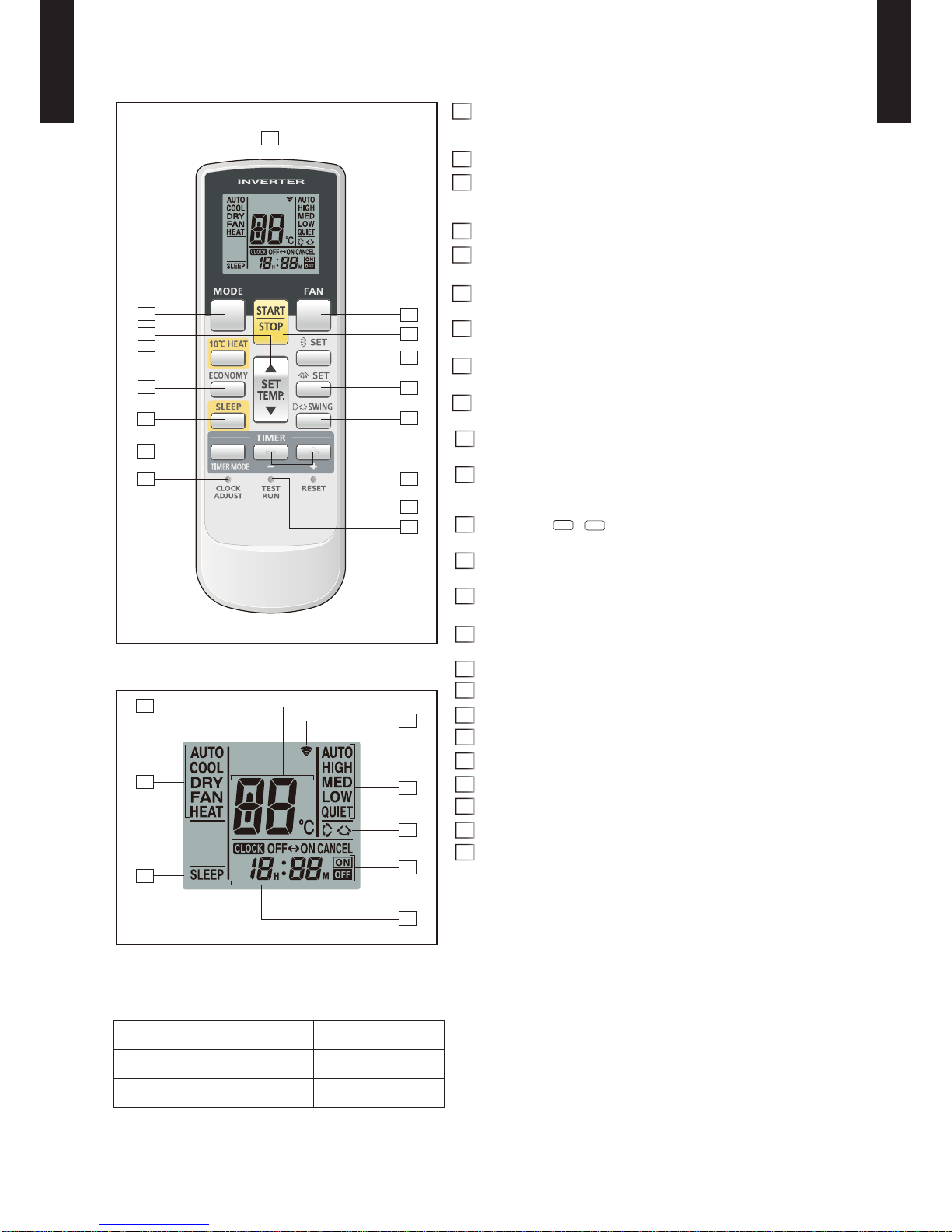
WIRELESS REMOTE CONTROLLER2.
FEATURES
Simple function setting
z
Setting of the air conditioner selection function is performed by remote controller.
Built-in timers
z
Select from 4 different timer programs (ON / OFF / PROGRAM / SLEEP).
Program timer
z
The program timer operates the on and off timer once within a 24-hour period.
Sleep timer
z
The sleep timer function automatically corrects the temperature thermostat setting according to
the time setting to prevent excessive cooling and heating while sleeping.
60min.
1°C
2°C
Timer setting
1°C
2°C
3°C
4°C
30min.
60min.
90min.
Timer setting
Cooling operation / dry operation
When the sleep timer is set, the set temperature
automatically rises 1 °C every hour. The set
temperature can rise up to a maximum of 2 °C.
Heating operation
When the sleep timer is set, the set temperature
automatically drops 1 °C every 30 minutes. The set
temperature can drop to a maximum of 4 °C.
Switching remote controller custom code
z
Code selector switch eliminates unit
•
being wrongly switched.
(Up to 4 codes can be set.)
*I.U.=Indoor unit
A B C D
A B
C
D
Mixed-up
I.U. I.U. I.U. I.U.
I.U. I.U. I.U. I.U.
After code change
4 mode timer setup available (ON / OFF / PROGRAM / SLEEP). ●
Can be used jointly with wired remote controllers . ●
Easy to change custom code (max. 4 units) by button operation. ●
Page 8
- (01 - 05) -
WALL MOUNTED TYPE
AS
G18-30LFC(C)A
WALL MOUNTED TYPE
AS
G18-30LFC(C)A
FUNCTIONS
MODE button1
Selects the operating mode (AUTO, COOL, DRY, FAN, HEAT).
/Start / end R.C. custom code change. (Max 4 types)
10°C2
HEAT button
SET TEMP. button ( ▲ / ▼ )3
Set remote controller custom code buttons
Sets the indoor temp./ Sets R.C. custom code.
ECONOMY button4
SLEEP button5
Pressed to select sleep timer.
FAN button6
Selects the fan speed (AUTO, HIGH, MED, LOW, QUIET).
START/STOP button7
Pressed to start and stop operation.
SET button (Vertical)8
Airow direction vertical set button.
SET button (Horizontal)9
Airow direction horizontal set button.
SWING button10
Airow direction swing button.
TIMER MODE button11
Pressed to select the timer mode. (OFF TIMER, ON TIMER,
PROGRAM TIMER, TIMER RESET)
TIMER set ( / ) button12
Sets the current time and on-off time.
CLOCK ADJUST button13
Sets the current time.
RESET button14
Used when replacing batteries.
TEST RUN button15
Used when testing the air conditioner after installation.
Signal transmitter16
Temperature set indicator17
Operating mode indicator18
Sleep indicator19
Transmit indicator20
Fan speed indicator21
Swing indicator22
Timer mode indicator23
Clock indicator24
Display panel
NOTE:
Functions will be different due to type of indoor unit.
For details, refer to the operation manual.
+
-
SPECIFICATION
SIZE (H × W × D mm) 170 × 56 × 19
WEIGHT (g) 85 (w/o batteries)
ACCESSORY Holder
2
4
9
3
1
16
15
5
10
13
11
12
14
8
7
6
17
18
19
21
24
23
22
20
Page 9
- (01 - 06) -
WALL MOUNTED TYPE
AS
G18-30LFC(C)A
WALL MOUNTED TYPE
AS
G18-30LFC(C)A
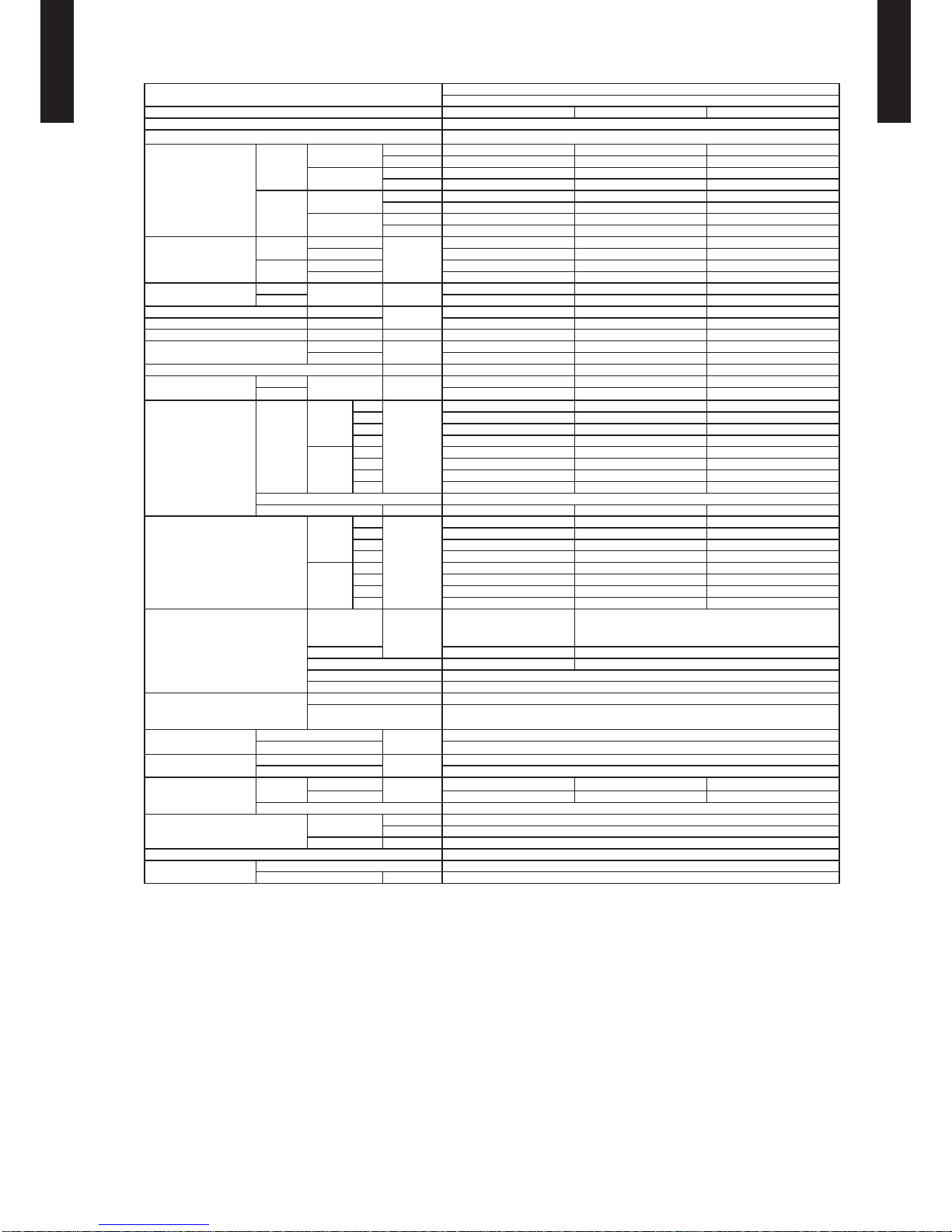
SPECIFICA TIONS3.
Typ e
WALL MOU NTED
INVERT ER HEAT PUM P
Model na me AS
G18LFCA ASG24LFCC ASG30LFCA
Power source 230 V~ 50 Hz
Available voltage range 198 –26 4V
Capacity
Cooling
Rated
kW 5.20 7.10 8.00
Btu/h 17,700 24,200 27, 3 00
Min.–Max.
kW 0.9–6.0 0.9– 8 .0 2.9–9.0
Btu/h 3,100–20,500 3,100–27,300 9,900–30,700
Heating
Rated
kW 6.30 8.00 8.80
Btu/h 21,500 27, 30 0 30,000
Min.–Max.
kW 0.9–9.1 0.9–10.6 2.2–11.0
Btu/h 3,100–31,000 3,100–36,200 7,5 00 – 37, 60 0
Input power
Cooling
Rated
kW
1.52 2.20 2.49
Min.–Max. 0.09–2.07 0.30–3.07 0.58–3.87
Heating
Rated 1.71 2.21 2.44
Min.–Max. 0.09–2.87 0.28–4.21 0.50–4.33
Current
Cooling
Rated A
6.8 9.7 10.9
Heating 7.6 9.7 10.7
EER Cooling
kW/kW
3.42 3.23 3.21
COP Heating 3.68 3.61 3.61
Sensibl e capac ity Cooling kW 3.45 5.25 6.00
Power fact or
Cooling
%
97 99 99
Heating 98 99 99
Moisture removal l/h (pints/h) 2.6(4.6) 2.7(4.8) 3.2(5.6)
Maximum operat ing
current *
Cooling
Max. A
9.0 13.5 17.0
Heating 12.5 18.5 19.0
Fan
Airow
rate
Cooling
High
m
3
/h
900 1120 1100
Med 740 900 900
Low 620 740 740
Quiet 550 580 620
Heating
High 900 1120 1150
Med 740 900 900
Low 620 740 740
Quiet 550 580 620
Type × Q'ty Cross ow fan × 1
Motor out put W 42 65 42
Sound pressure level
Cooling
High
dB (A)
43 49 48
Med 37 42 42
Low 33 37 37
Quiet 26 32 33
Heating
High 42 48 49
Med 37 42 42
Low 33 37 37
Quiet 25 32 33
Heat exchanger type
Dimensions
(H × W × D)
mm
Main : 378 × 832 × 26.6
Sub : 84 × 832 × 13.3
Main : 378 × 832 × 26.6
Sub1 : 84 × 832 × 13.3,
Sub2 : 84 × 83 2 × 13.3
Fin pitch Main :1.2, Sub :1.4 Main : 1.2, Sub1 : 1.4, Sub2 : 1.4
Rows × stag es Main : 2 × 18, Sub :1 × 4 Main : 2 × 18, Sub1 : 1 × 4, Sub2 : 1 × 4
Pipe typ e Copper
Fin type Aluminium
Enclosure
Material Polystyrene
Colour
White
Approximate colour of MU NSELL N 9.25/
Dimensions
(H × W × D)
Net
mm
320 × 998 × 238
Gross 329 × 1090 × 420
Weight
Net
kg
14
Gross 18
Connec tion pipe
Size
Liquid
mm
Ø 6.35 (Ø 1/4 in.) Ø 6.35 (Ø 1/4 in.) Ø 9.52 (Ø 3/8 in.)
Gas Ø 12.70 (Ø 1/2 in.) Ø 15.88 (Ø 5/8 in.) Ø 15.88 (Ø 5/8 in.)
Method Flare
Operat ion rang e
Cooling
°C 18 to 32
%RH 80 or less
Heating °C 30 or less
Remote co ntroller type Wireless
Drain ho se
Material PVC
Size mm Ø 12 (I.D.), Ø 16 (O.D.)
NOTES:
l
Specications are based on the following conditions:
Cooling : Indoor temperature of 27 °CDB/19 °CW B and outdoor temperature of 35 °CDB/24 °CWB
Heating : Indoor temperature of 20 °CDB/15 °CWB and outdoor temperature of 7 °CDB/6 °CWB
Pipe length : 5 m, Height difference : 0 m (Outdo or unit–Indoor unit)
l
The protective function might work when using it in environment out of the temperature range mentioned above.
* : The maximum current is the ma ximum value when operated within the operation range.
Page 10
- (01 - 07) -
WALL MOUNTED TYPE
AS
G18-30LFC(C)A
WALL MOUNTED TYPE
AS
G18-30LFC(C)A
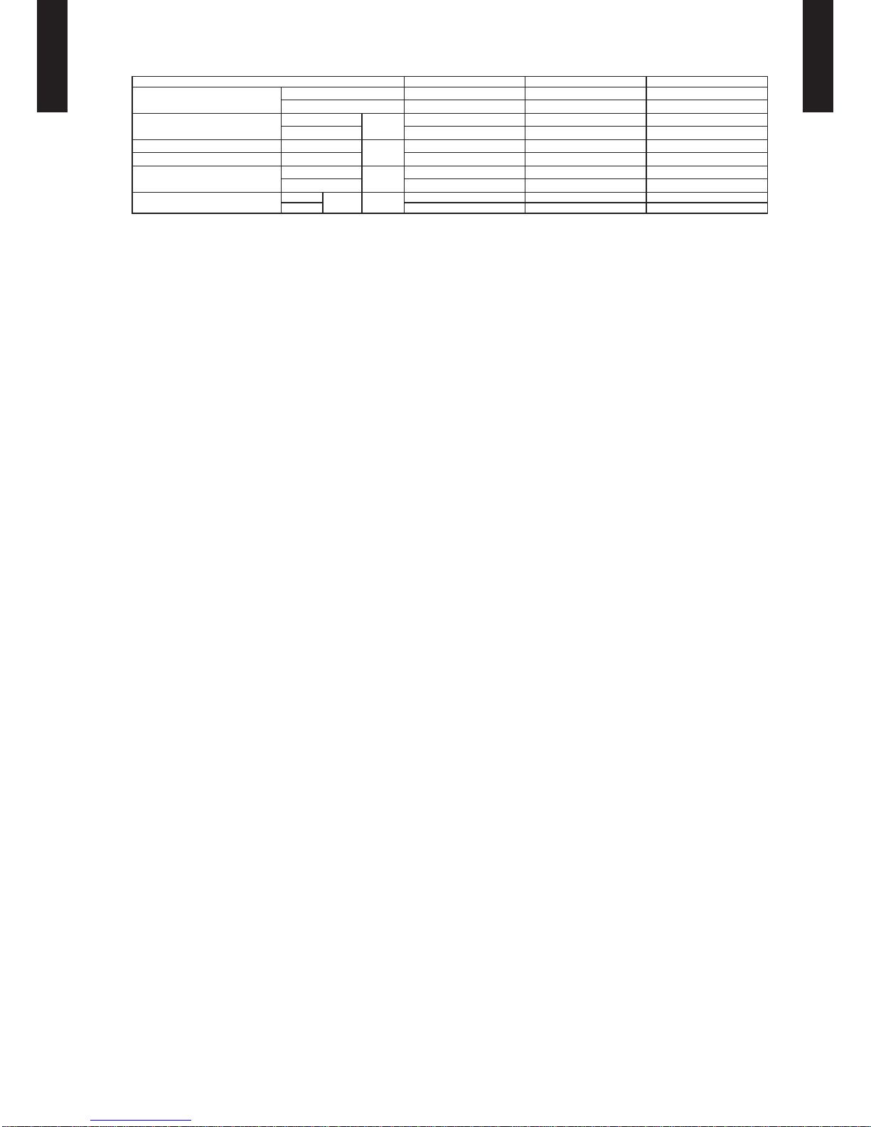
Model na me ASG18LFCA ASG24LFCC ASG30LFCA
Energy ef cie ncy clas s
Cooling A++ A++ A+
Heating (Average) A A A
Pdesign
Cooling
kW
5.2 (35 °C) 7.1 (35 °C) 8.0 (35 °C)
Heating (Average) 5.9 (-10 °C) 7.1 (-10 °C) 8.0 (-10 °C)
SEER Cooling
kWh/kWh
6.94 6.11 5.69
SCOP Heating (Average) 3.87 3.80 3.80
Annual energy co nsumpti on
QCE
kWh/a
262 406 492
QHE (Average) 2130 2610 2941
Sound power level
Cooling
High dB (A)
58 64 64
Heating 58 64 64
Page 11
- (01 - 08) -
WALL MOUNTED TYPE
AS
G18-30LFC(C)A
WALL MOUNTED TYPE
AS
G18-30LFC(C)A
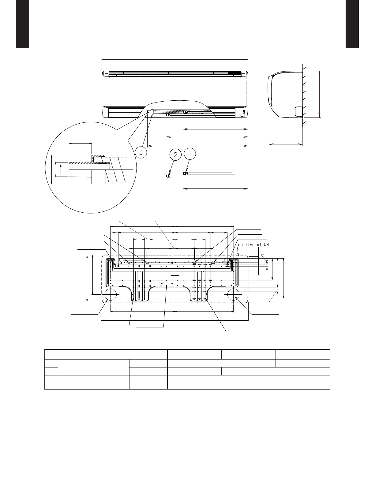
DIMENSIONS4.
MODEL : ASG18LFCA, ASG24LFCC, ASG30LFCA
(Unit : mm)
AS
G18LF ASG24LF ASG30LF
Refrigerant pipe are
connection
Liquid ø 6.35 mm (1/4 in.) ø 9.52 mm (3/8 in.)
Gas ø 12.7 mm (1/2 in.) ø 15.88 mm (5/8 in.)
Drain hose connection Drain hose
Ø12 (I.D.), Ø16 (O.D.)
Drain hose : L=670 mm
998
439
438
397
320: Unit size
269
20
37
26 x 11 hole
5 x 18: 14holes
21 x 5: 14holes
5 x 50: 3holes
13 x 5: 4holes
ø 80 hole
ø 5: 65holes
998: Unit size
Piping inlet
for tapping screw
18 x 11 hole
18 x 11 hole
122
172
75
387
170
16
400
Unit center
126
133
130
113
75
243
238
320
520
520
590
721
ø 80 hole
Piping inlet
30
30
149
197
272
44
12
13
26 x 11 hole
25
ø 32
ø 16
ø 12
Page 12
- (01 - 09) -
WALL MOUNTED TYPE
AS
G18-30LFC(C)A
WALL MOUNTED TYPE
AS
G18-30LFC(C)A
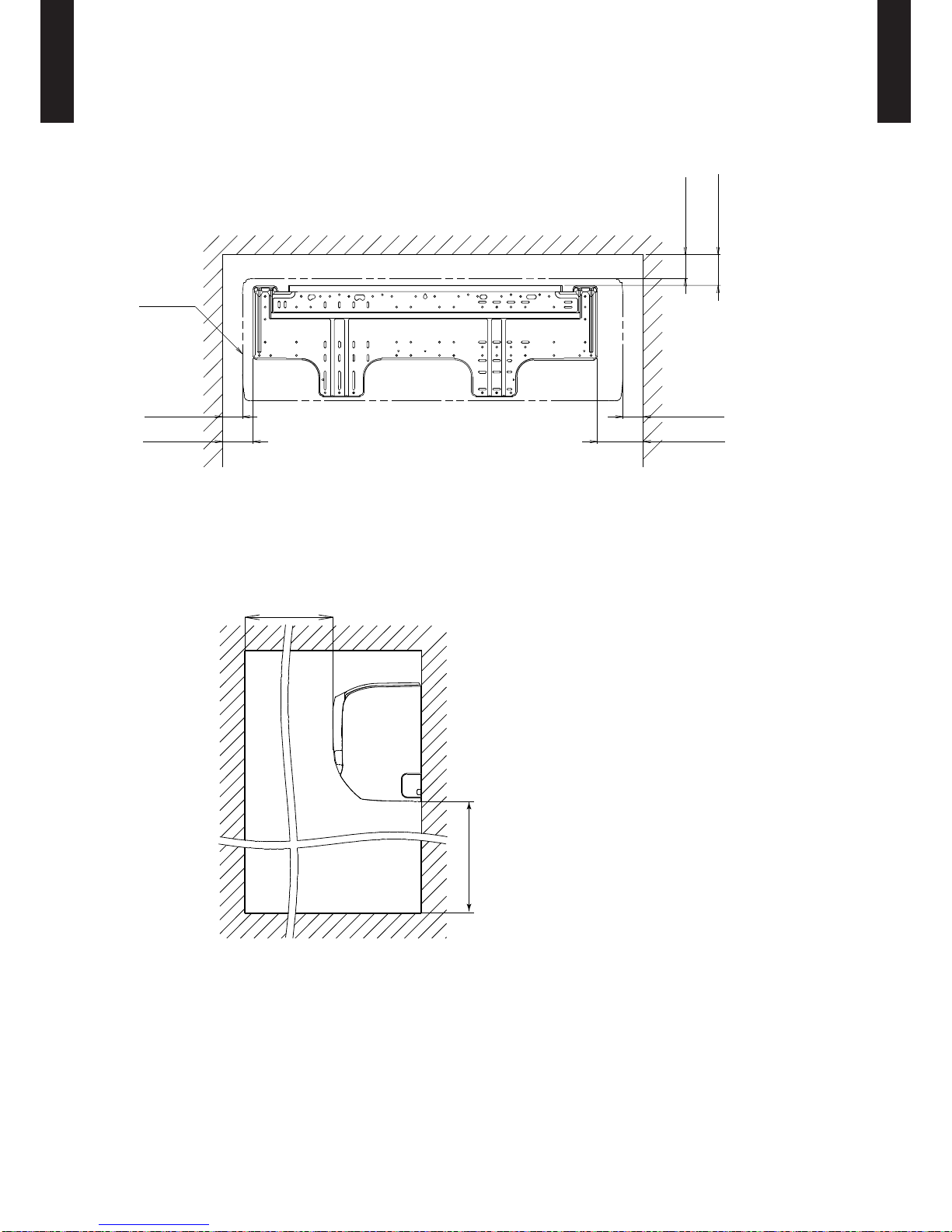
INSTALLATION PLACE
(Unit : mm)
63 or more
80 or more
53 or more
52 or more
80 or more
Outline of unit
120 or more
1500 or more
1800 or more
Page 13
- (01 - 10) -
WALL MOUNTED TYPE
AS
G18-30LFC(C)A
WALL MOUNTED TYPE
AS
G18-30LFC(C)A
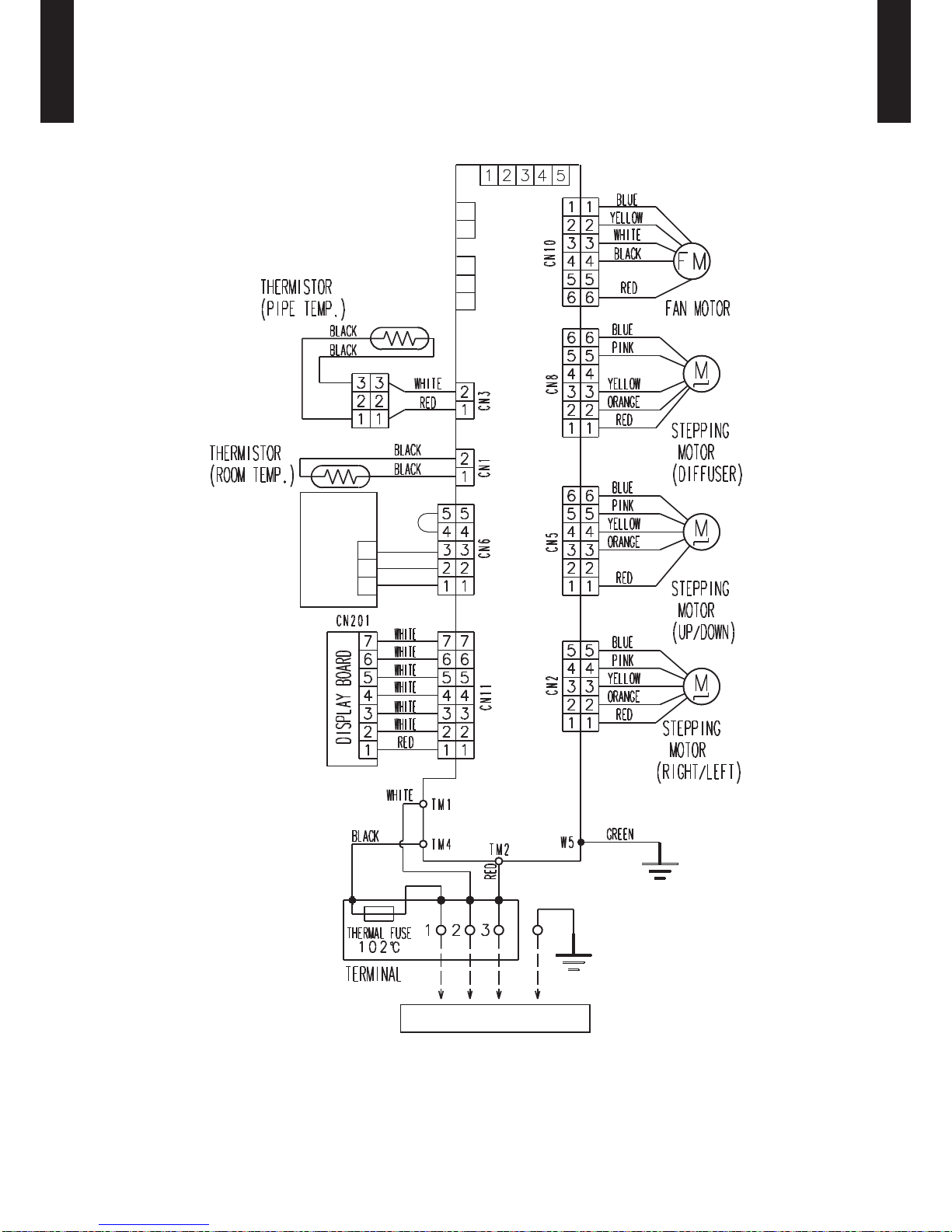
WIRING DIAGRAMS5.
MODEL : ASG18LFCA, ASG24LFCC, ASG30LFCA
TO OUTDOOR UNIT
CONTROOL BOARD
TEST
CN13
CN14
2
1
CN16
EX.OUT
(OPTION)
EX.IN
(OPTION)
1
2
3
BLACK
WHITE
RED
REMOTE CONTROL
UNIT (OPTION)
3
2
1
Page 14
- (01 - 11) -
WALL MOUNTED TYPE
AS
G18-30LFC(C)A
WALL MOUNTED TYPE
AS
G18-30LFC(C)A
CAPACITY TABLE6.
COOLING CAPACITY6-1.
MODEL : ASG18LFCA
MODEL
: ASG24LFCC
MODEL
: ASG30LFCA
AFR : Air ow Rate (m3/min)
TC : Total Capaci ty (kW)
SHC : Sens ible Hea t Capacit y (kW)
IP : Input Pow er (kW)
AFR 15.0
Indoor temperature
°CDB 18 21 23 25 27 29 32
°CWB 12 15 16 18 19 21 23
Outdoor temperature
°CDB TC SHC IP TC SHC IP TC SHC IP TC SHC IP TC SHC IP TC SHC IP TC SHC IP
20 4.62 3.14 1.03 5.15 3.15 1.05 5.33 3.43 1.05 5.68 3.44 1.06 5.85 3.71 1.07 6.20 3.70 1.08 6.56 3.94 1.09
25 4.63 3.14 1.17 5.16 3.16 1.19 5.34 3.43 1.20 5.69 3.45 1.21 5.86 3.72 1.22 6.21 3.71 1.23 6.57 3.95 1.24
30 4.38 2.97 1.32 4.88 2.99 1.34 5.04 3.25 1.35 5.38 3.26 1.36 5.54 3.52 1.37 5.87 3.50 1.38 6.21 3.73 1.39
35 4.11 2.91 1.47 4.58 2.93 1.49 4.73 3.18 1.50 5.04 3.19 1.51 5.20 3.45 1.52 5.51 3.44 1.54 5.82 3.66 1.55
40 3.56 2.41 1.35 3.96 2.43 1.38 4.10 2.64 1.38 4.37 2.65 1.40 4.50 2.86 1.40 4.78 2.85 1.42 5.05 3.03 1.43
46 3.08 2.09 1.65 3.43 2.10 1.68 3.55 2.28 1.68 3.78 2.29 1.70 3.90 2.48 1.71 4.13 2.47 1.73 4.37 2.63 1.74
AFR 18.7
Indoor temperature
°CDB 18 21 23 25 27 29 32
°CWB 12 15 16 18 19 21 23
Outdoor temperature
°CDB TC SHC IP TC SHC IP TC SHC IP TC SHC IP TC SHC IP TC SHC IP TC SHC IP
20 5.72 4.53 1.17 6.37 4.56 1.19 6.59 4.96 1.19 7.02 4.97 1.20 7.24 5.37 1.21 7.67 5.35 1.22 8.11 5.70 1.23
25 6.41 4.90 1.84 7.15 4.93 1.87 7.39 5.36 1.88 7.88 5.38 1.90 8.12 5.81 1.91 8.61 5.79 1.93 9.09 6.16 1.95
30 6.19 4.71 2.02 6.90 4.74 2.05 7.13 5.15 2.06 7.60 5.17 2.08 7.84 5.58 2.09 8.31 5.56 2.11 8.78 5.92 2.13
35 5.61 4.43 2.09 6.25 4.46 2.13 6.46 4.85 2.14 6.89 4.86 2.16 7.10 5.25 2.21 7.53 5.23 2.19 7.95 5.57 2.21
40 5.08 4.11 2.08 5.66 4.13 2.12 5.85 4.50 2.13 6.24 4.51 2.15 6.43 4.87 2.16 6.82 4.85 2.18 7.20 5.17 2.20
46 4.62 3.88 2.24 5.15 3.91 2.27 5.32 4.25 2.29 5.68 4.26 2.31 5.85 4.60 2.32 6.20 4.58 2.34 6.55 4.88 2.37
AFR 18.3
Indoor temperature
°CDB 18 21 23 25 27 29 32
°CWB 12 15 16 18 19 21 23
Outdoor temperature
°CDB TC SHC IP TC SHC IP TC SHC IP TC SHC IP TC SHC IP TC SHC IP TC SHC IP
20 6.31 5.01 1.29 7.03 5.04 1.31 7.27 5.48 1.32 7.75 5.50 1.33 7.99 5.94 1.34 8.47 5.92 1.35 8.95 6.30 1.37
25 6.99 5.45 2.03 7.79 5.48 2.06 8.05 5.96 2.07 8.58 5.98 2.09 8.85 6.46 2.10 9.38 6.43 2.12 9.91 6.85 2.14
30 6.66 5.23 2.26 7.42 5.26 2.29 7.67 5.72 2.30 8.18 5.74 2.33 8.43 6.20 2.34 8.94 6.18 2.36 9.44 6.58 2.39
35 6.32 5.06 2.40 7.04 5.09 2.44 7.28 5.54 2.45 7.76 5.56 2.48 8.00 6.00 2.49 8.48 5.98 2.51 8.96 6.37 2.54
40 5.68 4.63 2.68 6.33 4.66 2.72 6.54 5.07 2.74 6.97 5.08 2.77 7.19 5.49 2.78 7.62 5.47 2.81 8.05 5.82 2.84
46 5.17 4.22 2.89 5.76 4.25 2.93 5.96 4.62 2.95 6.35 4.63 2.98 6.55 5.00 2.99 6.94 4.98 3.02 7.34 5.31 3.05
Page 15
- (01 - 12) -
WALL MOUNTED TYPE
AS
G18-30LFC(C)A
WALL MOUNTED TYPE
AS
G18-30LFC(C)A
HEATING CAPACITY6-2.
MODEL : ASG18LFCA
MODEL
: ASG24LFCC
MODEL
: ASG30LFCA
AFR: Air ow Rate (m3/min)
TC : Total Capaci ty (kW)
IP : Input Pow er (kW)
AFR 15.0
Indoor t empera ture
16 18 20 22 24
Outdoo r temper ature
(°CD B) (°CWB) TC IP TC IP TC IP TC IP TC IP
-15 -16 5.08 2.19 4.96 2.24 4.84 2.30 4.72 2.33 4.60 2.37
-10 -11 6.04 2.36 5.89 2.42 5.75 2.47 5.61 2.52 5.47 2.57
-5 -7 6.81 2.48 6.64 2.54 6.48 2.59 6.32 2.64 6.16 2.69
0 -2 7.86 2.65 7.67 2.72 7.48 2.77 7.29 2.83 7.11 2.89
5 3 8.94 2.83 8.72 2.90 8.51 2.96 8.30 3.01 8.09 3.08
7 6 9.56 2.75 9.33 2.82 9.10 2.87 8.87 2.92 8.65 2.99
10 8 9.91 2.75 9.66 2.82 9.43 2.87 9.19 2.92 8.97 2.99
15 10 9.59 2.38 9.36 2.44 9.13 2.49 8.90 2.54 8.68 2.59
AFR 18.7
Indoor t empera ture
16 18 20 22 24
Outdoo r temper ature
(°CD B) (°CWB) TC IP TC IP TC IP TC IP TC IP
-15 -16 6.41 2.81 6.26 2.87 6.11 2.93 5.95 2.99 5.80 3.05
-10 -11 7.30 3.00 7.13 3.06 6.96 3.12 6.78 3.18 6.61 3.25
-5 -7 8.23 3.23 8.04 3.29 7.84 3.36 7.64 3.43 7.45 3.49
0 -2 9.05 3.50 8.84 3.58 8.62 3.65 8.40 3.72 8.19 3.80
5 3 10.05 3.82 9.81 3.90 9.57 3.98 9.33 4.06 9.09 4.14
7 6 11.13 3.89 10.87 3.97 10.60 4.06 10.34 4.14 10.07 4.22
10 8 11.19 3.38 10.93 3.45 10.66 3.52 10.39 3.59 10.13 3.66
15 10 10.71 2.90 10.46 2.96 10.20 3.02 9.95 3.08 9.69 3.13
AFR 19.2
Indoor t empera ture
16 18 20 22 24
Outdoo r temper ature
(°CD B) (°CWB) TC IP TC IP TC IP TC IP TC IP
-15 -16 7.75 4.07 7.56 4.16 7.38 4.24 7.20 4.32 7.01 4.41
-10 -11 8.34 4.06 8.14 4.15 7.94 4.23 7.74 4.31 7.54 4.40
-5 -7 9.61 4.08 9.38 4.17 9.15 4.25 8.92 4.34 8.69 4.42
0 -2 10.54 4.04 10.29 4.13 10.04 4.21 9.79 4.29 9.54 4.38
5 3 11.53 4.09 11.25 4.17 10.98 4.26 10.71 4.35 10.43 4.43
7 6 11.55 3.39 11.28 3.46 11.00 3.53 10.73 3.60 10.45 3.67
10 8 11.90 3.38 11.61 3.45 11.33 3.52 11.05 3.59 10.76 3.66
15 10 11.48 2.95 11.20 3.01 10.93 3.07 10.66 3.13 10.38 3.19
Page 16

- (01 - 13) -
WALL MOUNTED TYPE
AS
G18-30LFC(C)A
WALL MOUNTED TYPE
AS
G18-30LFC(C)A
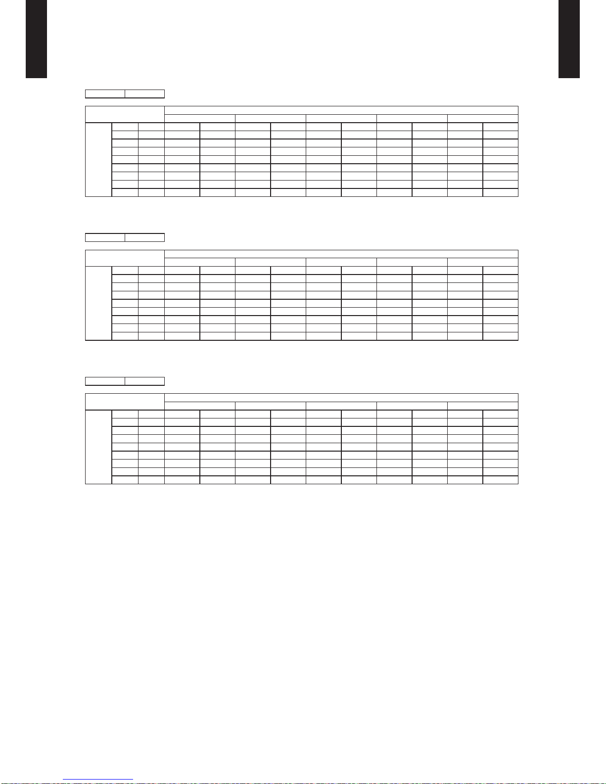
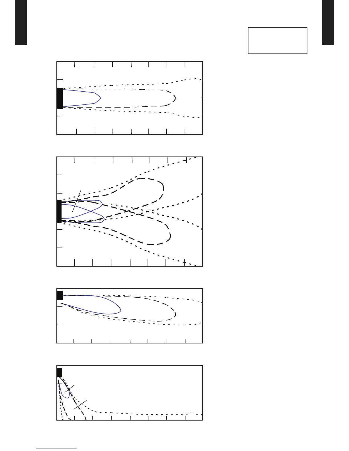
FAN PERFORMANCE7.
AIR VELOCITY DISTRIBUTION7-1.
MODEL : ASG18LFCA
Conditions:
Fan speed : HIGH
Operation mode : FAN
Voltage : 230 V
2
1
0
1
2
(m)
(m)
Unit : m/s
0 1 2 3 4 5 6 7 8
3
2
1
0
1
2
3
(m)
(m)
Unit : m/s
0 1 2 3 4 5 6 7 8
3
2
1
0
(m)
(m)
Unit : m/s
0 1 2 3 4 5 6 7 8
3
2
1
0
(m)
(m)
Unit : m/s
0 1 2 3 4 5 6 7 8
Side view
Vertic al air ow direction lou ver : Down
Horizo ntal air ow direction l ouver : Cent er
2.0
1.0
0.5
Side view
Vertic al air ow direction lou ver : Up
Horizo ntal air ow direction l ouver : Cent er
2.0
1.0
0.5
Top view
Vertic al air ow direction lou ver : Up
Horizo ntal air ow direction l ouver : Rig ht & Left
1.0
1.0
0.5
0.5
2.0
Top view
Vertic al air ow direction lou ver : Up
Horizo ntal air ow direction l ouver : Cent er
2.0 1.0 0.5
Page 17
- (01 - 14) -
WALL MOUNTED TYPE
AS
G18-30LFC(C)A
WALL MOUNTED TYPE
AS
G18-30LFC(C)A
MODEL : ASG24LFCC, ASG30LFCA
Conditions:
Fan speed : HIGH
Operation mode : FAN
Voltage : 230 V
2
1
0
1
2
(m)
(m)
Unit : m/s
0 1 2 3 4 5 6 7 8
3
2
1
0
1
2
3
(m)
(m)
Unit : m/s
0 1 2 3 4 5 6 7 8
3
2
1
0
(m)
(m)
Unit : m/s
0 1 2 3 4 5 6 7 8
3
2
1
0
(m)
(m)
Unit : m/s
0 1 2 3 4 5 6 7 8
Side view
Vertic al air ow direction lou ver : Down
Horizo ntal air ow direction l ouver : Cent er
2.0
1.0
0.5
Side view
Vertic al air ow direction lou ver : Up
Horizo ntal air ow direction l ouver : Cent er
2.0
1.0
0.5
Top view
Vertic al air ow direction lou ver : Up
Horizo ntal air ow direction l ouver : Rig ht & Left
1.0
1.0
0.5
0.5
2.0
Top view
Vertic al air ow direction lou ver : Up
Horizo ntal air ow direction l ouver : Cent er
2.0 1.0 0.5
Page 18

- (01 - 15) -
WALL MOUNTED TYPE
AS
G18-30LFC(C)A
WALL MOUNTED TYPE
AS
G18-30LFC(C)A
AIRFLOW7-2.
MODEL : ASG18LFCA
Cooling
z
Heating
z
Fan speed
Number of
rotations
(r.p.m.)
Airow
HIGH 1220
m
3
/h 900
l/s 250
CFM 530
MED 1020
m
3
/h 740
l/s 206
CFM 435
LOW 900
m
3
/h 620
l/s 172
CFM 365
QUIET 710
m
3
/h 550
l/s 153
CFM
324
Fan speed
Number of
rotations
(r.p.m.)
Airow
HIGH 1220
m
3
/h 900
l/s 250
CFM 530
MED 1020
m
3
/h 740
l/s 206
CFM 435
LOW 900
m
3
/h 620
l/s 172
CFM 365
QUIET 710
m
3
/h 550
l/s 153
CFM
324
Page 19

- (01 - 16) -
WALL MOUNTED TYPE
AS
G18-30LFC(C)A
WALL MOUNTED TYPE
AS
G18-30LFC(C)A
MODEL : ASG24LFCC
Cooling
z
Heating
z
Fan speed
Number of
rotations
(r.p.m.)
Airow
HIGH 1480
m
3
/h 1120
l/s 311
CFM 659
MED 1220
m
3
/h 900
l/s 250
CFM 530
LOW 1020
m
3
/h 740
l/s 206
CFM 435
QUIET 860
m
3
/h 580
l/s 161
CFM 341
Fan speed
Number of
rotations
(r.p.m.)
Airow
HIGH 1480
m
3
/h 1120
l/s 311
CFM 659
MED 1220
m
3
/h 900
l/s 250
CFM 530
LOW 1020
m
3
/h 740
l/s 206
CFM 435
QUIET 860
m
3
/h 580
l/s 161
CFM 341
Page 20

- (01 - 17) -
WALL MOUNTED TYPE
AS
G18-30LFC(C)A
WALL MOUNTED TYPE
AS
G18-30LFC(C)A
MODEL : ASG30LFCA
Cooling
z
Heating
z
Fan speed
Number of
rotations
(r.p.m.)
Airow
HIGH 1430
m
3
/h 1100
l/s 306
CFM 647
MED 1220
m
3
/h 900
l/s 250
CFM 530
LOW 1020
m
3
/h 740
l/s 206
CFM 435
QUIET 900
m
3
/h 620
l/s 172
CFM 365
Fan speed
Number of
rotations
(r.p.m.)
Airow
HIGH 1530
m
3
/h 1150
l/s 319
CFM 677
MED 1220
m
3
/h 900
l/s 250
CFM 530
LOW 1020
m
3
/h 740
l/s 206
CFM 435
QUIET 900
m
3
/h 620
l/s 172
CFM 365
Page 21

- (01 - 18) -
WALL MOUNTED TYPE
AS
G18-30LFC(C)A
WALL MOUNTED TYPE
AS
G18-30LFC(C)A
OPERATION NOISE (SOUND PRESSURE)8.
NOISE LEVEL CURVE8-1.
MODEL : ASG18LFCA
NC-65
NC-60
NC-55
NC-50
NC-45
NC-40
NC-35
NC-30
NC-25
NC-20
NC -15
NC-65
NC-60
NC-55
NC-50
NC-45
NC-40
NC-35
NC-30
NC-25
NC-20
NC -15
NC-65
NC-60
NC-55
NC-50
NC-45
NC-40
NC-35
NC-30
NC-25
NC-20
NC -15
NC-65
NC-60
NC-55
NC-50
NC-45
NC-40
NC-35
NC-30
NC-25
NC-20
NC -15
High
Quiet
Octave ba nd sound p ressur e level, dB : (0 dB= 0.00 02 µbar)
Octave ba nd cente r freque ncy, Hz
80
70
60
50
40
30
20
10
0
63 125 250 5 00 1,00 0 2,00 0 4,00 0 8,000
MODEL : ASG24LFCC
Cooling
z
Heating
z
Octave ba nd sound p ressur e level, dB : (0 d B=0. 0002 µ bar)
Octave ba nd cente r freque ncy, Hz
80
70
60
50
40
30
20
10
0
63 125 250 5 00 1,00 0 2,00 0 4,00 0 8,000
Heating
z
Octave ba nd sound p ressur e level, dB : (0 d B=0. 0002 µ bar)
Octave ba nd cente r freque ncy, Hz
80
70
60
50
40
30
20
10
0
63 125 250 5 00 1,00 0 2,00 0 4,00 0 8,000
High
Quiet
Cooling
z
Octave ba nd sound p ressur e level, dB : (0 d B=0. 0002 µ bar)
Octave ba nd cente r freque ncy, Hz
80
70
60
50
40
30
20
10
0
63 125 250 5 00 1,00 0 2,00 0 4,00 0 8,000
High
Quiet
High
Quiet
Page 22

- (01 - 19) -
WALL MOUNTED TYPE
AS
G18-30LFC(C)A
WALL MOUNTED TYPE
AS
G18-30LFC(C)A
MODEL : ASG30LFCA
High
Quiet
High
Quiet
Heating
z
Octave ba nd sound p ressur e level, dB : (0 d B=0. 0002 µ bar)
Octave ba nd cente r freque ncy, Hz
80
70
60
50
40
30
20
10
0
63 125 250 5 00 1,00 0 2,00 0 4,00 0 8,000
NC-65
NC-60
NC-55
NC-50
NC-45
NC-40
NC-35
NC-30
NC-25
NC-20
NC -15
Cooling
z
Octave ba nd sound p ressur e level, dB : (0 d B=0. 0002 µ bar)
Octave ba nd cente r freque ncy, Hz
80
70
60
50
40
30
20
10
0
63 125 250 5 00 1,00 0 2,00 0 4,00 0 8,000
NC-65
NC-60
NC-55
NC-50
NC-45
NC-40
NC-35
NC-30
NC-25
NC-20
NC -15
Page 23

- (01 - 20) -
WALL MOUNTED TYPE
AS
G18-30LFC(C)A
WALL MOUNTED TYPE
AS
G18-30LFC(C)A
SOUND LEVEL CHECK POINT8-2.
Page 24

- (01 - 21) -
WALL MOUNTED TYPE
AS
G18-30LFC(C)A
WALL MOUNTED TYPE
AS
G18-30LFC(C)A
ELECTRICAL CHARACTERISTICS9.
Model name AS
G18LFCA ASG24LFCC ASG30LFCA
Power supply
Volt ag e V 230 ~
Frequency Hz 50
Max. operating current A 0.3
Wiring Spec. *
1
Connection cable mm
2
1.5–2.5
Limited wiring length m 26 31 51
*
1
: Selected sample based on Japan Electrotechnical Standards and Codes Committee E0005.
Page 25

- (01 - 22) -
WALL MOUNTED TYPE
AS
G18-30LFC(C)A
WALL MOUNTED TYPE
AS
G18-30LFC(C)A
SAFETY DEVICES10.
Protection form
Model
ASG18LFCA
ASG30LFCA
ASG24LFCC
Circuit protection Current fuse (PC board) 250 V 3.15 A
Terminal protection Current (thermal) fuse 250 V 3 A
Fan motor protection Thermal protector program
OFF : 150 ± 15 °C
ON : 120 ± 15 °C
OFF : 120 ± 15 °C
ON : 95 ± 10 °C
Page 26

- (01 - 23) -
WALL MOUNTED TYPE
AS
G18-30LFC(C)A
WALL MOUNTED TYPE
AS
G18-30LFC(C)A
EXTERNAL INPUT & OUTPUT11.
Connector INPUT OUTPUT REMARKS
CN14 Control input - See external
input/output settings
for details.
CN16 - Operation status output
EXTERNAL INPUT11-1.
CONTROL INPUT (Operation/Stop or Forced stop)
The air conditioner can be remotely operated by means of the following on-site work.
"Operation/Stop" mode or "Forced stop" mode can be selected with function setting of indoor unit.
Unit operation is started at the following contents by adding the contact input of a commercial ON/OFF switch to a
connector on the external control PC board and turning it ON.
Unit operation Initial setting after power is ON Starting mode other than initial setting
Operation mode Auto changeover Mode at previous operation
Set temperature 24 °C Temperature at previous operation
Airow mode AUTO Mode at previous operation
Up-down air direction (swing) Standard air direction (swing OFF) Air direction at previous operation
Left-right air direction (swing) Standard air direction (swing OFF) Air direction at previous operation
Circuit diagram example
z
Indoor unit
control PC board Connected unit
Ex.) Switch
Connector
1
3
Signal
Field supply
*: Make the distance from the PC board to the connected unit within 10 m.
Contact capacity : DC 24 V or more, 10 mA or more.
Use non-polar relays and switches.
10 m*
When function setting is in "Operation/Stop" mode
z
Operation
Stop
ON
OFF
Input signal
Indoor unit
Page 27

- (01 - 24) -
WALL MOUNTED TYPE
AS
G18-30LFC(C)A
WALL MOUNTED TYPE
AS
G18-30LFC(C)A
When function setting is in "Forced stop" mode
z
Remote controller
ON ON ON
Input signal
ON
OFF
Indoor unit
Operation
Stop
Command
Forced stop
Normal
Remote control
operation invalidity
Parts (Optional)
z
Parts name
Model name
External connect kit UT Y-X WZX
Page 28

- (01 - 25) -
WALL MOUNTED TYPE
AS
G18-30LFC(C)A
WALL MOUNTED TYPE
AS
G18-30LFC(C)A
EXTERNAL OUTPUT11-2.
OPERATION STATUS OUTPUT
An air conditioner operation status signal can be output.
Circuit diagram example
z
Field supply
Ex.) Display
Indoor unit
control PC board
Connected unit
Ex.)Relay unit
1
2
Signal
Relay
power
supply
V
Connector
*: Make the distance from the PC board to the connected unit within 10 m.
Relay spec. : Max. DC 24 V, 10 mA to less than 500 mA.
10 m*
DC 24V
ON
OFF
Operation
Stop
Indoor unit
Output signal
Parts (Optional)
z
Parts name
Model name
External connect kit UT Y-X WZX
Page 29

- (01 - 26) -
WALL MOUNTED TYPE
AS
G18-30LFC(C)A
WALL MOUNTED TYPE
AS
G18-30LFC(C)A
FUNCTION SETTINGS12.
INDOOR UNIT (Setting by remote controller)12-1.
The function settings of the control of the indoor unit can be changed by this procedure according •
to the installation conditions. Incorrect settings can cause the indoor unit to malfunction.
After the power is turned on, perform the Function Setting according to the installation conditions
•
using the remote controller.
The settings may be selected between the following two: Function Number or Setting Value.
•
Settings will not be changed if invalid numbers or setting values are selected.
•
FUNCTION SETTING METHOD (for Wireless remote controller)
Entering the Function Setting Mode
While pressing the FAN button and SET TEMP. (
•
) simultaneously, press the RESET button to enter the function
setting mode.
STEP 1
Setting the Remote controller Custom Code
Use the following steps to select the custom code of the remote controller. (Note
that the air conditioner cannot receive a custom code if the air conditioner has not
been set for the custom code.) The custom codes that are set through this process
are applicable only to the signals in the Function Setting. For details on how to set
the custum codes through the normal process, refer to REMOTE CONTROLLER
CUSTOM CODE SETTING.
Press the SET TEMP. (1
. ) ( ) button to change the custom code between →
→ → Match the code on the display to the air conditioner custom code. (initially
set to )
(If the custom code does not need to be selected, press the MODE button and
proceed to STEP 2.)
Press the TIMER MODE button and check that the indoor unit can receive signals 2
.
at the displayed custom code.
Press the MODE button to accept the custom code, and proceed to STEP 2.3
.
The air conditioner custom code is set to A prior to shipment.
The remote controller resets to custom code A when the batteries in the remote controller are replaced. If you use a
custom code other than custom code A, reset the custom code after replacing the batteries.
If you do not know the air conditioner custom code setting, try each of the custom codes (
→ → → ) until
you nd the code which operates the air conditioner.
STEP 2
Selecting the Function Number and Setting Value
Press the SET TEMP. (1
. ) ( ) buttons to select the function
numbe r.
(Press the MODE button to switch between the left and right
digits.)
Press the FAN button to proceed to setting the value. 2
.
Press the FAN button again to return to the function number
selection.)
Press the SET TEMP. (3
. ) ( ) buttons to select the setting
value.
(Press the MODE button to switch between the left and right
digits.)
Press the TIMER MODE button, and START/STOP button, 4
.
in the order listed to conrm the settings.
Press the RESET button to cancel the function setting 5
.
mode.
After completing the Function Setting, be sure to turn off the 6
.
power and turn it on again.
Function number
Setting value
CAUTION
After turning off the power, wait 30 seconds or more before turning on it again.
The Function Setting will not become active unless the power is turned off then on again.
Page 30

- (01 - 27) -
WALL MOUNTED TYPE
AS
G18-30LFC(C)A
WALL MOUNTED TYPE
AS
G18-30LFC(C)A
FUNCTION DETAILS
Follow the instructions in the Local Setup Procedure, which is supplied with the remote controller, in •
accordance with the installed condition.
After turning on the power, perform the Function Setting by using the remote controller.
The settings may be selected between the following two: Function Number or Setting Value.
•
Settings will not be changed if invalid numbers or setting values are selected.
•
1) Filter sign
2) Room temperature control for cooling
3) Room temperature control for heating
4) Auto restart
5) Room temperature sensor switching
6) Remote controller custom code
7) External input control
8) Indoor unit fan control for energy saving for cooling
1) Filter sign
Select appropriate intervals for displaying the lter sign on the indoor unit according to the estimated
amount of dust in the air of the room.
If the indication is not required, select "No indication" (03).
(
. . .Factory setting)
Setting Description Function Number Setting Value
Standard (400 hours)
11
00
Long interval (1,000 hours) 01
Short interval (200 hours) 02
No indication 03
2) Room temperature control for cooling
Depending on the installed environment, correction of the room temperature sensor may be required.
Select the appropriate control setting according to the installed environment.
(
. . .Factory setting)
Setting Description Function Number Setting Value
Standard
30
00
Slightly lower control 01
Lower control 02
Higher control 03
3) Room temperature control for heatling
Depending on the installed environment, correction of the room temperature sensor may be required.
Select the appropriate control setting according to the installed environment.
(
. . .Factory setting)
Setting Description Function Number Setting Value
Standard
31
00
Slightly lower control 01
Lower control 02
Higher control 03
Page 31

- (01 - 28) -
WALL MOUNTED TYPE
AS
G18-30LFC(C)A
WALL MOUNTED TYPE
AS
G18-30LFC(C)A
4) Auto restart
Enable or disable automatic restart after a power interruption.
(
. . .Factory setting)
Setting Description Function Number Setting Value
Enable
40
00
Disable 01
*
Auto restart is an emergency function such as for power outage etc. Do not attempt to use this function in
normal operation.
Be sure to operate the unit by remote controller or other external input device.
5) Room temperature sensor switching
(Only for wired remote controller)
When using the Wired remote controller temperture sensor, change the setting to "Both" (01).
(
. . .Factory setting)
Setting Description Function Number Setting Value
Indoor unit
42
00
Both 01
00: Sensor on the indoor unit is active.
01: Sensors on both indoor unit and wired remote controller are active.
6) Remote controller custom code
(Only for wireless remote controller)
The indoor unit custom code can be changed. Select the appropriate custom code.
(
. . .Factory setting)
Setting Description Function Number Setting Value
A
44
00
B 01
C 02
D 03
7) External input control
"Operation/Stop" mode or "Forced stop" mode can be selected.
(
. . .Factory setting)
Setting Description Function Number Setting Value
Operation/Stop mode
46
00
(Setting prohibited) 01
Forced stop mode 02
8) Indoor unit fan control for energy saving for cooling
Enables or disables the power-saving function by controlling the indoor unit fan rotation when the outdoor
unit is stopped during cooling operation.
(
. . .Factory setting)
Setting Description Function Number Setting Value
Disable
49
00
Enable 01
00: When the outdoor unit is stopped, the indoor unit fan operates continuously following the setting on the
remote controller.
01: When the outdoor unit is stopped, the indoor unit fan operates intermittently at a very low speed.
Page 32

- (01 - 29) -
WALL MOUNTED TYPE
AS
G18-30LFC(C)A
WALL MOUNTED TYPE
AS
G18-30LFC(C)A
REMOTE CONTROLLER CUSTOM CODE SETTING
Use the following steps to select the custom code of the remote controller.
(Note that the air conditioner cannot receive a custom code if the air conditioner has
not been set for the custom code.)
Press the START/STOP button until only the clock is displayed on the remote 1
.
controller display.
Press the MODE button for at least ve seconds to display the current custom 2
.
code (initially set to ).
Press the SET TEMP. (3. ) ( ) button to change the custom code between →
→ → .
Match the code on the display to the air conditioner custom code.
Press the MODE button again to return to the clock indicator. The custom code will 4
.
be changed.
If no buttons are pressed within 30 seconds after the custom code is displayed, the system returns to the original
clock indicator. In this case, start again from step 1.
The air conditioner custom code is set to A prior to shipment.
Contact your retailer to change the custom code.
The remote controller resets to custom code A when the batteries in the remote controller are replaced. If you use a
custom code other than custom code A, reset the custom code after replacing the batteries. If you do not know the
air conditioner custom code setting, try each of the custom codes (
→ → → ) until you nd the code which
operates the air conditioner.
Page 33

- (01 - 30) -
WALL MOUNTED TYPE
AS
G18-30LFC(C)A
WALL MOUNTED TYPE
AS
G18-30LFC(C)A
OPTIONAL PARTS13.
CONTROLLERS13-1.
OTHERS13-2.
Exterior Parts name Model No. Summary
Wired remote
controller
UTY- RVN
M
Large and full-dot liquid crystal
screen, wide and large keys
easy to press, user-intuitive
arrow key.
Wired remote
controller
UTY- RNN
M
The room temperature can
be controlled by detecting the
temperature accurately with
built-in thermo sensor.
Simple remote
controller
UTY- RSN
M
Compact remote controller
concentrates on the basic
functions such as Start/Stop,
Fan Control, Temperature
Setting and Operation mode.
Exterior Parts name Model No. Summary
External
connect kit
UTY-X W ZX
Use to connect with various
peripheral devices and air
conditioner PC board.
Page 34

2. OUTDOOR UNIT
SINGLE TYPE :
AOG18LFC
AOG24LFCC
AOG30LFT
DTR_AO128E_03
2016.04.22
Page 35

OUTDOOR UNIT
AO
G18-30LF
OUTDOOR UNIT
AO
G18-30LF
CONTENTS
2. OUTDOOR UNIT
1. SPECIFICATIONS
..............................................................................................02 - 01
2. DIMENSIONS
........................................................................................................02 - 02
3. REFRIGERANT CIRCUIT
............................................................................ 02 - 04
4. WIRING DIAGRAMS
........................................................................................02 - 07
5. CAPACITY COMPENSATION RATE FOR PIPE LENGTH AND
HEIGHT DIFFERENCE
.................................................................................. 02 - 10
6. ADDITIONAL CHARGE CALCULATION
......................................... 02 - 13
7. AIRFLOW
.................................................................................................................02 - 14
8. OPERATION NOISE (SOUND PRESSURE)
................................. 02 - 16
8-1. NOISE LEVEL CURVE
....................................................................................02 - 16
8-2. SOUND LEVEL CHECK POINT
..................................................................... 02 - 18
9. ELECTRICAL CHARACTERISTICS
................................................... 02 - 19
10. SAFETY DEVICES
............................................................................................ 02 - 20
Page 36

- (02 - 01) -
OUTDOOR UNIT
AO
G18-30LF
OUTDOOR UNIT
AO
G18-30LF
SPECIFICA TIONS1.
Type INVERTER HEAT PUMP
Model name AO
G18LFC AO
G24LFCC
AO
G30LFT
Power source 230 V~ 50 Hz
Available voltage range 198–264 V
Starting current A 7.6 9.7 10.9
Fan
Airow
rate
Cooling
m
3
/h
2,150 2,460 3,600
Heating 2,070 2,340 3,600
Type × Q'ty Propeller fan × 1
Motor output W 49 49 100
Sound pressure level
Cooling
dB(A)
50 55 53
Heating 51 56 55
Sound power level
Cooling
dB(A)
65 68 68
Heating 66 69 71
Heat exchanger type
Dimensions
(H × W × D)
mm
588 × 881 × 36.4
Main : 588 × 881 × 36.4
Sub : 546 × 580 × 18.2
798 × 900 × 36.4
Fin pitch 1.3 1.45 1.3
Rows × Stages 2 × 28
Main : 2 × 28,
Sub : 1 × 26
2 × 38
Pipe type Co pper
Fin
Type (Material) Corrugate (Aluminium)
Surface treatment
Corrosion resistance
Corrosion resistance
(Blue n)
Compressor
Type × Q'ty Rotary ×1
Motor output W 900 1,100 2,100
Refrigerant
Type (Global Warming Potential) R410A (1975)
Charge g 1,200 1,800 2,100
Refrigerant oil Type FREOLα68SZ POE (RB68)
Enclosure
Material Steel
Colour
Beige
Approximate colour of MUNSELL 10YR7.5/1.0
Dimensions
( H × W × D)
Net
mm
620 × 790 × 290 830 × 900 × 330
Gross 713 × 945 × 395 1000 × 1050 × 445
Weight
Net
kg
41 61
Gross 45 69
Connection pipe
Size
Liquid
mm
Ø 6.35 (Ø 1/4 in.) Ø 9.52 (Ø 3/8 in.)
Gas Ø 12.7 (Ø 1/2 in.)
Ø 15.88 (Ø 5/8 in.)
Method Flare
Pre-charge length
m
15 15 20
Max. length 25 30 50
Max. height difference 20 20 30
Operation range
Cooling
°C
-10 to 46
Heating -15 to 24
NOTES :
Specications are based on the following conditions:
•
•
Cooling : Indoor temperature of 27 °CDB / 19 °CWB and outdoor temperature of 35 °CDB / 24 °CWB
Heating : Indoor temperature of 20 °CDB / 15 °CWB and outdoor temperature of 7 °CDB / 6 °CWB
Pipe length : 5 m, Height difference : 0 m (Outdoor unit–Indoor unit)
The protective function might work when using it in environment out of the temperature range mentioned above.
•
•
Page 37

- (02 - 02) -
OUTDOOR UNIT
AO
G18-30LF
OUTDOOR UNIT
AO
G18-30LF
DIMENSIONS2.
MODEL• : AOG18LFC, AOG24LFCC
(Unit : mm)
INSTALLATION PLACE
•
(Unit : mm)
If the space is larger than stated, the condition will be the same as those without any obstacles.
600 or more
100 or more
200 or more
100 or more
250 or more
(Service space)
Pitch of bolts for installation
353
45.4
320
395
540
125
Drain port Ø20
20
790
620
20
62
290
Page 38

- (02 - 03) -
OUTDOOR UNIT
AO
G18-30LF
OUTDOOR UNIT
AO
G18-30LF
MODEL• : AOG30LFT
(Unit : mm)
INSTALLATION PLACE
•
600 mm
or more
100 mm
or more
600 mm or more
300 mm
or more
100 mm
or more
300 mm or more
(Service space)
250 mm
or more
250 mm
or more
300 mm
or more
When there are obstacles at
the back or front sides.
When there are obstacles at
the back, side(s), and top.
When there are obstacles at the
back, side with the installation of
more than one unit.
Airflow
900
650
830
370
99
196
21
9
77
31 330
400
170
147
12
Top view
Front view
Side view
Bottom view
Page 39

- (02 - 04) -
OUTDOOR UNIT
AO
G18-30LF
OUTDOOR UNIT
AO
G18-30LF
REFRIGERANT CIRCUIT3.
MODEL• : AOG18LFC
Th
R
Th
D
Th
P
Th
O
Th
HO
: Thermistor (Discharge Temp.)
: Thermistor (Outdoor Temp.)
: Thermistor (Heat Exchanger Out Temp.)
Th
D
Th
O
Th
HO
: Thermistor (Room Temp.)
: Thermistor (Pipe Temp.)
Th
R
Th
P
: Cooling
: Heating
Refrigerant pipe diameter
Liquid : 1/4" (6.35 mm)
Gas : 1/2" (12.7 mm)
Page 40

- (02 - 05) -
OUTDOOR UNIT
AO
G18-30LF
OUTDOOR UNIT
AO
G18-30LF
MODEL• : AOG24LFCC
Refrigerant pipe diameter
Liquid : 1/4" (6.35 mm)
Gas : 5/8" (15.88 mm)
2-Way
valve
Strainer
Strainer
3-Way
valve
Muffler
4-Way valve
Expansion valve
Heat exchanger
( INDOOR )
Heat exchanger
( OUTDOOR )
Compressor
: Cooling
: Heating
Muffler
Pressure
switch
Sub-accumulator
Th
C
Th
R
Th
D
Th
P
Th
O
Th
HO
Th
C
: Thermistor (Compressor Temp.)
: Thermistor (Discharge Temp.)
: Thermistor (Outdoor Temp.)
: Thermistor (Heat Exchanger Out Temp.)
Th
D
Th
O
Th
HO
: Thermistor (Room Temp.)
: Thermistor (Pipe Temp.)
Th
R
Th
P
Page 41

- (02 - 06) -
OUTDOOR UNIT
AO
G18-30LF
OUTDOOR UNIT
AO
G18-30LF
MODEL• : AOG30LFT
3-Way
valve
(Small)
3-Way
valve
(Large)
Strainer
Strainer
Muffler
Pressure
switch
4-Way valve
Expansion valve
Heat exchanger
( INDOOR )
Heat exchanger
( OUTDOOR )
Sub-accumulator
Compressor
: Cooling
: Heating
Th
C
Th
R
Th
D
Th
P
Th
O
Th
HO
Th
C
: Thermistor (Compressor Temp.)
: Thermistor (Discharge Temp.)
: Thermistor (Outdoor Temp.)
: Thermistor (Heat Exchanger Out Temp.)
Th
D
Th
O
Th
HO
: Thermistor (Room Temp.)
: Thermistor (Pipe Temp.)
Th
R
Th
P
Refrigerant pipe diameter
Liquid : 3/8" (9.52 mm)
Gas : 5/8" (15.88 mm)
Page 42

- (02 - 07) -
OUTDOOR UNIT
AO
G18-30LF
OUTDOOR UNIT
AO
G18-30LF
WIRING DIAGRAMS4.
MODEL• : AOG18LFC
Page 43

- (02 - 08) -
OUTDOOR UNIT
AO
G18-30LF
OUTDOOR UNIT
AO
G18-30LF
MODEL• : AOG24LFCC
Page 44

- (02 - 09) -
OUTDOOR UNIT
AO
G18-30LF
OUTDOOR UNIT
AO
G18-30LF
MODEL• : AOG30LFT
Page 45

- (02 - 10) -
OUTDOOR UNIT
AO
G18-30LF
OUTDOOR UNIT
AO
G18-30LF
CAPACITY COMPENSATION RATE FOR PIPE LENGTH 5.
AND HEIGHT DIFFERENCE
MODEL• : AOG18LFC
Height difference H
1: Indoor unit is higher than outdoor unit.
2: Indoor unit is lower than outdoor unit.
Indoor unit
Indoor unit
Connection pipe
Outdoor unit
Outdoor unit
Connection pipe
HEATING
Pipe length (m)
5 10 15 20 25
Height difference H
(m)
Û
1
Indoor unit is higher
than outdoor unit.
20 - - - 0.901 0.879
10 - 0.989 0.927 0.901 0.879
5 1.000 0.989 0.927 0.901 0.879
0 1.000 0.989 0.927 0.901 0.879
Û
2
Indoor unit is lower
than outdoor unit
-5 0.995 0.984 0.922 0.896 0.874
-10 - 0.979 0.917 0.892 0.869
-20 - - - 0.876 0.853
COOLING
Pipe length (m)
5 10 15 20 25
Height difference H
(m)
Û
1
Indoor unit is higher
than outdoor unit.
20 - - - 0.869 0.867
10 - 0.973 0.911 0.885 0.883
5 0.992 0.981 0.919 0.893 0.891
0 1.000 0.989 0.927 0.901 0.899
Û
2
Indoor unit is lower
than outdoor unit
-5 1.000 0.989 0.927 0.901 0.899
-10 - 0.989 0.927 0.901 0.899
-20 - - - 0.901 0.899
H H
Page 46

- (02 - 11) -
OUTDOOR UNIT
AO
G18-30LF
OUTDOOR UNIT
AO
G18-30LF
MODEL• : AOG24LFCC
Height difference H
1: Indoor unit is higher than outdoor unit.
2: Indoor unit is lower than outdoor unit.
Indoor unit
Indoor unit
Connection pipe
Outdoor unit
Outdoor unit
Connection pipe
HEATING
Pipe length (m)
5 7.5 10 15 20 25 30
Height
difference H
(m)
Û
1
Indoor unit is
higher than
outdoor unit.
20 - - - - 0.954 0.932 0.908
10 - - 0.998 0.975 0.954 0.932 0.908
7.5 - 1.000 0.998 0.975 0.954 0.932 0.908
5 1.000 1.000 0.998 0.975 0.954 0.932 0.908
0 1.000 1.000 0.998 0.975 0.954 0.932 0.908
Û
2
Indoor unit
is lower than
outdoor unit
-5 0.995 0.995 0.993 0.970 0.950 0.927 0.903
-7.5 - 0.993 0.991 0.968 0.947 0.925 0.901
-10 - - 0.988 0.965 0.945 0.923 0.899
-20 - - - - 0.935 0.914 0.890
COOLING
Pipe length (m)
5 7.5 10 15 20 25 30
Height
difference H
(m)
Û
1
Indoor unit is
higher than
outdoor unit.
20 - - - - 0.952 0.951 0.951
10 - - 0.980 0.966 0.968 0.967 0.966
7.5 - 0.988 0.984 0.970 0.972 0.971 0.970
5 0.992 0.992 0.988 0.974 0.976 0.975 0.974
0 1.000 1.000 0.996 0.982 0.983 0.983 0.982
Û
2
Indoor unit
is lower than
outdoor unit
-5 1.000 1.000 0.996 0.982 0.983 0.983 0.982
-7.5 - 1.000 0.996 0.982 0.983 0.983 0.982
-10 - - 0.996 0.982 0.983 0.983 0.982
-20 - - - - 0.983 0.983 0.982
H H
Page 47

- (02 - 12) -
OUTDOOR UNIT
AO
G18-30LF
OUTDOOR UNIT
AO
G18-30LF
MODEL• : AOG30LFT
Height difference H
1: Indoor unit is higher than outdoor unit.
2: Indoor unit is lower than outdoor unit.
Indoor unit
Indoor unit
Connection pipe
Outdoor unit
Outdoor unit
Connection pipe
HEATING
Pipe length (m)
5 7.5 10 20 30 40 50
Height
difference H
(m)
Û
1
Indoor unit is
higher than
outdoor unit.
30 - - - - 0.816 0.756 0.686
20 - - - 0.872 0.816 0.756 0.686
10 - - 0.991 0.872 0.816 0.756 0.686
7.5 - 1.000 0.991 0.872 0.816 0.756 0.686
5 1.000 1.000 0.991 0.872 0.816 0.756 0.686
0 1.000 1.000 0.991 0.872 0.816 0.756 0.686
Û
2
Indoor unit
is lower than
outdoor unit
-5 0.995 0.995 0.986 0.868 0.812 0.752 0.683
-7.5 - 0.993 0.983 0.866 0.810 0.750 0.681
-10 - - 0.981 0.864 0.808 0.748 0.679
-20 - - - 0.855 0.799 0.740 0.672
-30 - - - - 0.791 0.733 0.665
COOLING
Pipe length (m)
5 7.5 10 20 30 40 50
Height
difference H
(m)
Û
1
Indoor unit is
higher than
outdoor unit.
30 - - - - 0.932 0.929 0.924
20 - - - 0.945 0.947 0.945 0.940
10 - - 0.984 0.961 0.963 0.960 0.956
7.5 - 0.988 0.988 0.965 0.967 0.964 0.959
5 0.992 0.992 0.992 0.968 0.971 0.968 0.963
0 1.000 1.000 1.000 0.976 0.979 0.976 0.971
Û
2
Indoor unit
is lower than
outdoor unit
-5 1.000 1.000 1.000 0.976 0.979 0.976 0.971
-7.5 - 1.000 1.000 0.976 0.979 0.976 0.971
-10 - - 1.000 0.976 0.979 0.976 0.971
-20 - - - 0.976 0.979 0.976 0.971
-30 - - - - 0.979 0.976 0.971
H H
Page 48

- (02 - 13) -
OUTDOOR UNIT
AO
G18-30LF
OUTDOOR UNIT
AO
G18-30LF
ADDITIONAL CHARGE CALCULATION6.
MODEL• : AOG18LFC
Refrigerant charge
•z
MODEL• : AOG24LFCC
Refrigerant charge
•z
MODEL• : AOG30LFT
Refrigerant charge
•z
Refrigerant type R410A
Refrigerant amount g 1200
Total pipe length m 15 or less 20 25 (Max.)
20 g/m
Additional charge g 0 100 200
Refrigerant type R410A
Refrigerant amount g 1800
Total pipe length m 15 or less 20 25 30 (Max.)
20 g/m
Additional charge g 0 100 200 300
Refrigerant type R410A
Refrigerant amount g 2100
Total pipe length m 20 or less 30 40 50 (Max.)
40 g/m
Additional charge g 0 400 800 1200
Page 49

- (02 - 14) -
OUTDOOR UNIT
AO
G18-30LF
OUTDOOR UNIT
AO
G18-30LF
AIRFLOW7.
MODEL• : AOG18LFC
Cooling
•z
Heating
•z
MODEL• : AOG24LFCC
Cooling
•z
Heating
•z
Number of
rotations
(r.p.m.)
Airow
920
m
3
/h 2150
l/s 597
CFM 1265
Number of
rotations
(r.p.m.)
Airow
870
m
3
/h 2070
l/s 575
CFM 1218
Number of
rotations
(r.p.m.)
Airow
1100
m
3
/h 2460
l/s 683
CFM 1448
Number of
rotations
(r.p.m.)
Airow
1050
m
3
/h 2340
l/s 650
CFM 1377
Page 50

- (02 - 15) -
OUTDOOR UNIT
AO
G18-30LF
OUTDOOR UNIT
AO
G18-30LF
MODEL• : AOG30LFT
Cooling
•z
Heating
•z
Number of
rotations
(r.p.m.)
Airow
850
m
3
/h 3600
l/s 1000
CFM 2119
Number of
rotations
(r.p.m.)
Airow
850
m
3
/h 3600
l/s 1000
CFM 2119
Page 51

- (02 - 16) -
OUTDOOR UNIT
AO
G18-30LF
OUTDOOR UNIT
AO
G18-30LF
OPERATION NOISE (SOUND PRESSURE)8.
NOISE LEVEL CURVE8-1.
MODEL• : AOG18LFC
Cooling
•z
Octave band sound pressure level, dB : (0 dB=0.0002 µbar)
Octave band center frequency, Hz
80
70
60
50
40
30
20
10
0
63 125 250 500 1,000 2,000 4,000 8,000
NC-65
NC-60
NC-55
NC-50
NC-45
NC-40
NC-35
NC-30
NC-25
NC-20
NC-15
Heating
•z
Octave band sound pressure level, dB : (0 dB=0.0002 µbar)
Octave band center frequency, Hz
80
70
60
50
40
30
20
10
0
63 125 250 500 1,000 2,000 4,000 8,000
NC-65
NC-60
NC-55
NC-50
NC-45
NC-40
NC-35
NC-30
NC-25
NC-20
NC-15
Heating
•z
Octave band sound pressure level, dB : (0 dB=0.0002 µbar)
Octave band center frequency, Hz
80
70
60
50
40
30
20
10
0
63 125 250 500 1,000 2,000 4,000 8,000
NC-65
NC-60
NC-55
NC-50
NC-45
NC-40
NC-35
NC-30
NC-25
NC-20
NC-15
Octave band sound pressure level, dB: (0 dB=0.0002 µbar)
Octave band center frequency, Hz
80
70
60
50
40
30
20
10
0
63 125 250 500 1,000 2,000 4,000 8,000
MODEL• : AOG24LFCC
Cooling
•z
NC-65
NC-60
NC-55
NC-50
NC-45
NC-40
NC-35
NC-30
NC-25
NC-20
NC-15
Page 52

- (02 - 17) -
OUTDOOR UNIT
AO
G18-30LF
OUTDOOR UNIT
AO
G18-30LF
MODEL• : AOG30LFT
Cooling
•z
Octave band sound pressure level, dB : (0 dB=0.0002 µbar)
Octave band center frequency, Hz
80
70
60
50
40
30
20
10
0
63 125 250 500 1,000 2,000 4,000 8,000
NC-65
NC-60
NC-55
NC-50
NC-45
NC-40
NC-35
NC-30
NC-25
NC-20
NC-15
Heating
•z
Octave band sound pressure level, dB : (0 dB=0.0002 µbar)
Octave band center frequency, Hz
80
70
60
50
40
30
20
10
0
63 125 250 500 1,000 2,000 4,000 8,000
NC-65
NC-60
NC-55
NC-50
NC-45
NC-40
NC-35
NC-30
NC-25
NC-20
NC-15
Page 53

- (02 - 18) -
OUTDOOR UNIT
AO
G18-30LF
OUTDOOR UNIT
AO
G18-30LF
SOUND LEVEL CHECK POINT8-2.
Page 54

- (02 - 19) -
OUTDOOR UNIT
AO
G18-30LF
OUTDOOR UNIT
AO
G18-30LF
ELECTRICAL CHARACTERISTICS9.
Model name AOG18LFC AOG24LFCC AOG30LFT
Power supply
Voltage V 230 V ~
Frequency Hz 50
Max. operating current *
1
A
12.5 18.5
19.0
Starting current A 7.6 9.7 10.9
Wiring spec. *
2
Main fuse (Circuit breaker)
current
A
20
30
Power cable mm
2
3.5–4.0
Limited wiring length *
3
m 20
*1: The maximum current is the total current of indoor unit and outdoor unit.
*2: Selected sample based on Japan Electrotechnical Standards and Codes Committee E0005.
*3: This is the wiring length in case voltage descent is less than 2 %.
When the wiring length becomes long, select a wire with larger diameter.
Page 55

- (02 - 20) -
OUTDOOR UNIT
AO
G18-30LF
OUTDOOR UNIT
AO
G18-30LF
SAFETY DEVICES10.
Protection form
Model
AOG18LFC AOG24LFCC AOG30LFT
Circuit protection
Current fuse
(Near the terminal)
250 V 20 A � 250 V 20 A
250 V 5 A � 250 V 5 A
Current fuse
(Main PC board)
250 V 15 A 250 V 20 A 250 V 15 A
250 V 3.15 A 250 V 5 A 250 V 3.15 A
Fan motor
protection
Thermal protection
program
OFF : 100 ± 15 °C
ON : 95 ± 10 °C
OFF : 100 ± 15 °C
ON : 95 ± 10 °C
OFF : 150 ± 15 °C
ON : 120 ± 15 °C
Compressor
protection
Thermal protection program
(Compressor temp.)
�
OFF : 108 °C
ON : After 40 minutes
OFF : 108 °C
ON : After 40 minutes
Thermal protection program
(Discharge temp.)
OFF : 110 °C
ON : After 7 minutes
OFF : 110 °C
ON : After 7 minutes
OFF : 110 °C
ON : After 7 minutes
High pressure
protection
Pressure switch �
OFF : 4.2 ± 0.1 MPa
ON : 3.2 ± 0.15 MPa
OFF : 4.2 ± 0.1 MPa
ON : 3.2 ± 0.15 MPa
 Loading...