

Page 1

R410A
D1D_AS004E/03
2010.02.10
1. WALL MOUNTED
TYPE :
AS B24LDC
INDOOR UNIT
Page 2

- (01 - 01) -
WALL MOUNTED TYPE
AS B24LD
WALL MOUNTED TYPE
AS B24LD
MODEL : AS B24LDC
FEATURES
1. FEATURE
Energy saving Rank A
Original plasma air cleaning unit effectively cleans the air in the room.
Super quiet
ALL DC
Large air flow and quiet
operation by new air
flow path
V-PAM technology makes a compressor more powerful.
V P
More compact compared with conventional model
Front view
Back view
Air flow mode can be set in 4 steps and more detailed air flow setting is possible.
High efficiency
layout
New 3-row heat
exchange system
V-P
V-PAM control
b
DC scroll compressor
c
a
DC fan motor
DC fan motor
b
a
c
1
2
3
Dirty Air
Clean Air
Pet odor and the smell of
cigarette smoke are
removed by decomposition
by weak ozone O3.
Clean Air
Activated charcoal
bacteria eliminating &
deodorizing filter
Polyphenol filter
(Grapefruit seed extract)
Earth conductor
Plasma filter generates
ions and ozone.
Electric pole
Electrostatic
filter
Dirty Air
Negatively-charged dust, etc. are attracted
to the earth section and are collected by a
bacteria eliminating & deodorizing filter.
Plasma air filter mechanism
Washable filter
Restored to the same performance
as when new each time it is washed.
Plasma unit
Mounts a plasma air cleaning unit.Minute dust
particles are collected by an electrostatic filter and odor
is suppressed by decomposition of foul odors by very
weak ions. Since a filter with a lower ventilation
resistance than in the past is used, high dust collection
design simultaneously cleans in the air in the room.
Europe energy saving Rank A achieved
Page 3

- (01 - 02) -
WALL MOUNTED TYPE
AS B24LD
WALL MOUNTED TYPE
AS B24LD
Easy maintenance
Easy maintenance and always clean. Troublesome maintenance has been made easy.
Since the front panel is easy to remove, maintenance is also easy.
Inner drying operation and plasma effect
This model is equipped with an inner drying function. After the power is turned off, the dry operation starts
inside the air conditioner. The plasma air cleaning unit eliminates bacteria, deodorizes, and keeps
the interior of the air conditioner clean by generating ozone and ions.
Power diffuser
Adoption of large power diffuser
Compact design
998mm width compact design
Low outdoor air temperature cooling correspondence
Corresponds to cooling operation at -10°Coutdoor air temperature
New model
(unit:mm)
H320 x W998 x D228
2.52.5
5
0 3 6 9 12(m)
Outside air conditions: 2 oC 60%
( C)
Operation contents: Heating,
Set temperature (Max set temp)
30
o
o
C, Air flow Hi,
Air direction downward and front
“Strong vertical air flow” provides
powerful floor level heating.
Power diffuser
Power diffuser
(full open)
“Healthy horizontal air flow” does not blow
cool air directly at the occupants in the room.
5
2.5
0 3 6 9 12(m)
Corresponds to maximum 30m long piping
2933 32 31 30
Outside air conditions: 35 oC 40%
( C)
Operation contents: Cooling,
Set temperature (Min set temp)
18
o
o
C, Air flow Hi,
Air direction downward and front
1815 16 17
2.5
46
o
Bacteria grows in beading,
and it causes bad odor.
Drying operation for
approx. fifteen minutes.
Ozone bacteria eliminating operation
for approx. fifteen minutes.
“Inner drying operation” and
“ozone bacteria eliminating
operation” keep the inside
of the air conditioner clean
at all times. That ’s why air
from the air conditioner is
always clean and high
efficiency is realized.
After operation ends,
start approximately
30 minutes speed
cleaning operation
by merely pressing
the COIL DRY
button.
Removes moisture.
Bacteria elimination
Covered with beading.
Page 4
- (01 - 03) -
WALL MOUNTED TYPE
AS B24LD
WALL MOUNTED TYPE
AS B24LD
FEATURES
Four kinds of timer setup (ON / OFF / PROGRAM / SLEEP) are possible.
Four kinds of timers. Easy operation.
Select from four different timer programs (On/Off/Program/Sleep).
Built-in timers
The program timer operates the ON and OFF timer once within a 24 hour period.
Program timer
The sleep timer function automatically corrects the temperature thermostat setting according to the
time setting to prevent excessive cooling and heating while sleeping.
Sleep timer
2-1. WIRELESS REMOTE CONTROLLER
2.
REMOTE CONTROLLER
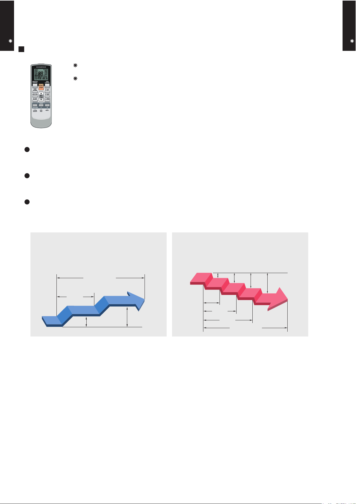
Cooling operation/dry operation
60min.
1 °C
2 °C
When the sleep timer is set, the set temperature
automatically rises 1 °C every hour. The set
temperature can rise up to a maximum of 2 °C.
Heating operation
When the sleep timer is set, the set temperature
automatically drops 1 °C every 30 minutes. The
set temperature can drop to a maximum of 4 °C.
1 °C
30min.
60min.
90min.
2 °C
3 °C
4 °C
Timer setting
Timer setting
Page 5
- (01 - 04) -
WALL MOUNTED TYPE
AS B24LD
WALL MOUNTED TYPE
AS B24LD
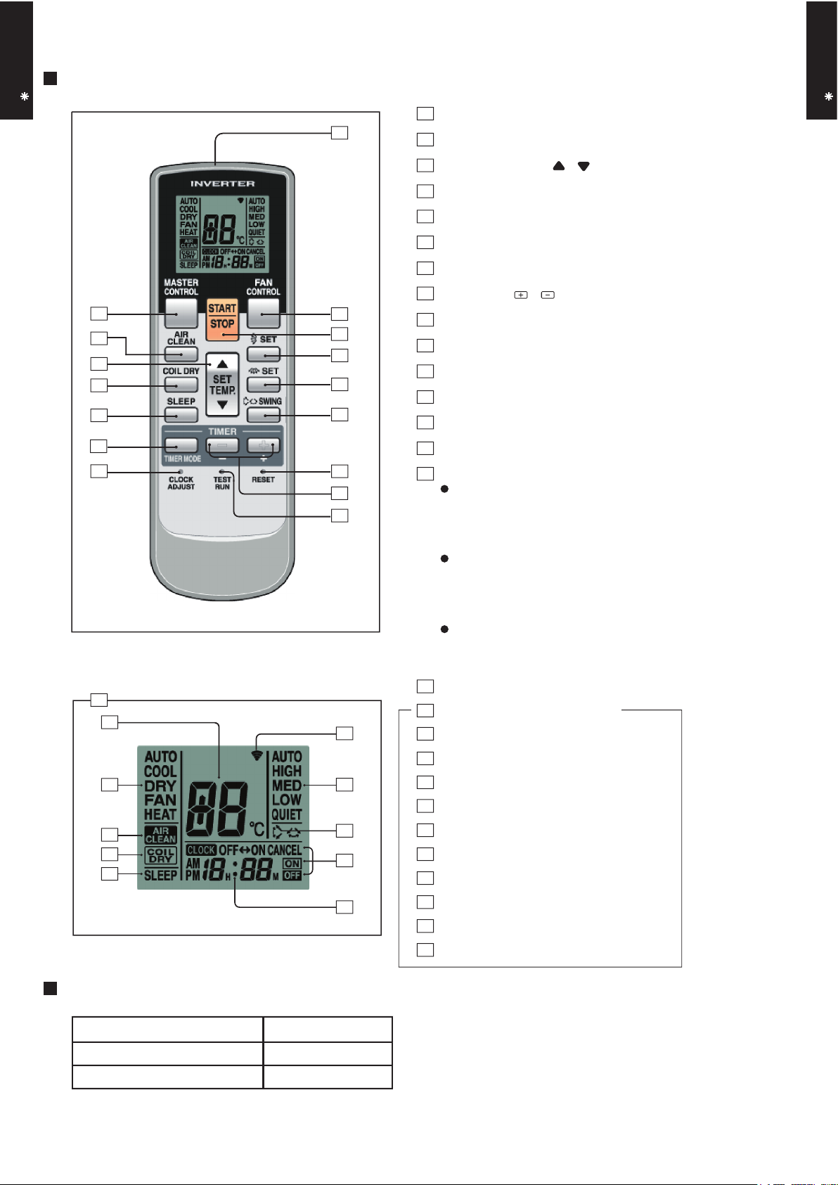
Display panel
FUNCTIONS
SPECIFICATION
SIZE (H x W x D mm) 176 x 56 x 18
WEIGHT ( g ) 110
ACCESSORY Holder
TIMER SET ( / ) button
SET button (Horizontal)
TEST RUN button
This button is used when installing the
conditioner, and should not be used under normal conditions, as it will cause the
air conditioner’s thermostat function to operate incorrectly.
If this button is pressed during normal operation, the unit will switch to test operation mode, and the Indoor Unit’s OPERATION Indicator Lamp and TIMER Indicator
Lamp will begin to flash simultaneously.
To stop the test operation mode, press the
START/STOP button to stop the air conditioner.
CLOCK ADJUST button
Remote Control Unit Display
Transmit Indicator
Clock Display
Operating Mode Display
Timer Mode Display
Fan Speed Display
Temperature SET Display
SLEEP button
MASTER CONTROL button
/ )
SET TEMP. button (
COIL DRY button
Signal Transmitter
TIMER MODE button
FAN CONTROL button
START/STOP button
SET button (Vertical)
SWING button
RESET button
AIR CLEAN Display
SLEEP Display
SWING Display
4
6
7
8
9
10
19
21
22
23
24
26
27
COIL DRY Display
25
20
18
2
3
11
13
12
16
17
15
1
14
AIR CLEAN button
5
2
4
10
3
1
16
6
18
19
20
22
26
25
23
27
11
14
12
13
15
9
8
7
21
5
24
17
Page 6

- (01 - 05) -
WALL MOUNTED TYPE
AS B24LD
WALL MOUNTED TYPE
AS B24LD
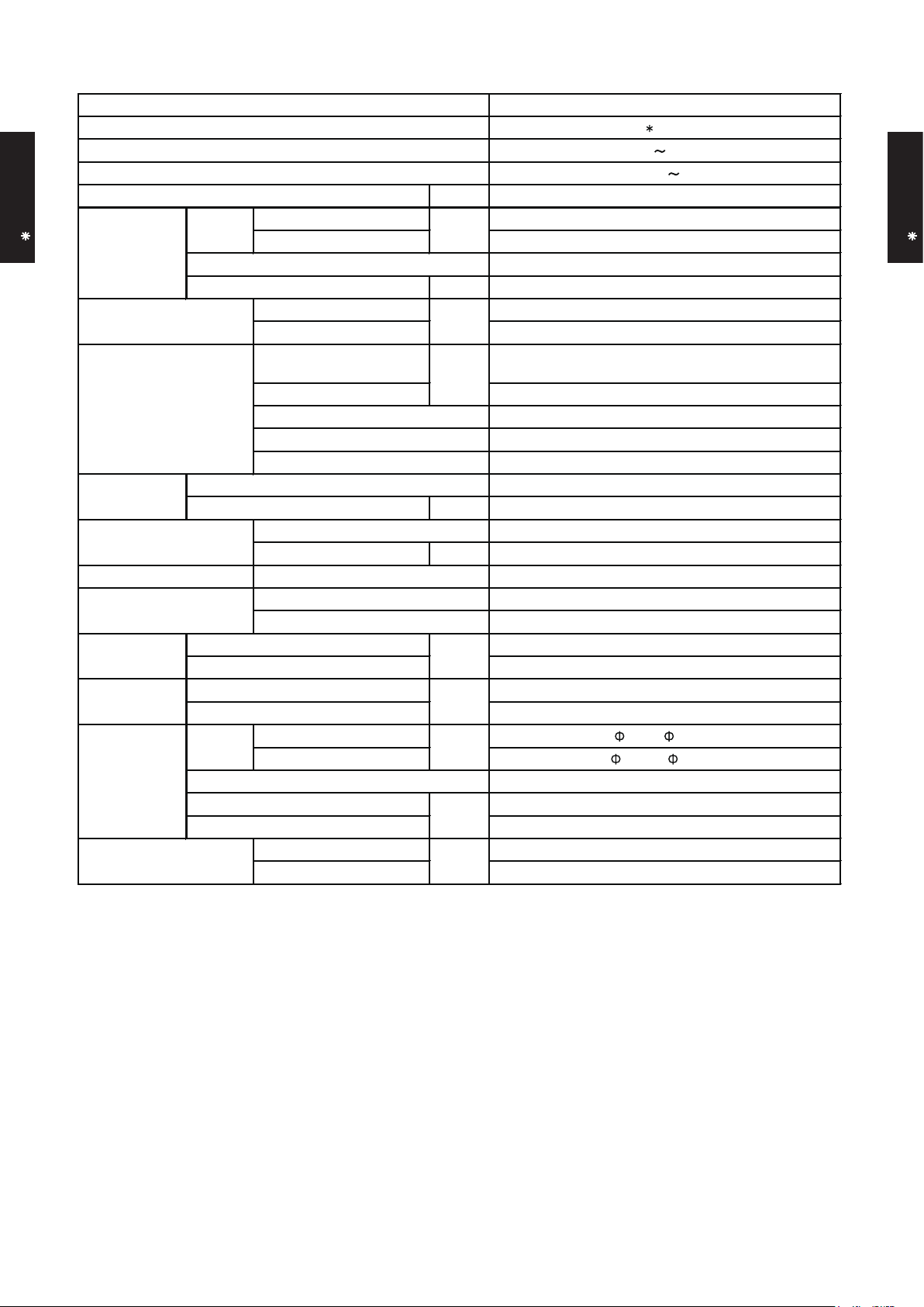
3. SPECIFICATIONS
WALL MOUNTED
INVERTER HEAT PUMP
AS B24LDC
230V 50Hz
198 - 264V 50Hz
Cooling A
Heating A
kW 7.10
BTU/h 24,200
kW 0.9 - 8.0
BTU/h 3,100 - 27,300
kW 8.10
BTU/h 27,600
kW 0.9 - 10.6
BTU/h 3,100 - 36,200
2.21
0.11 - 2.62
2.24
0.11 - 3.68
9.7
12
9.8
17.5
3.21
3.62
kW 5.54
99
99
l/h (pints/h) 3.0 (5.3)
High 1170
Med 970
Low 785
Quiet 685
High 1170
Med 970
Low 785
Quiet 685
Cross flow fan × 1
W 42
High 49
Med 43
Low 38
Quiet 33
High 48
Med 42
Low 37
Quiet 33
Dimensions (H × W × D)
Main : 378 × 832 × 26.6
Sub : 84 × 832 × 13.3
Main : 1.2, Sub : 1.4
Main : 2 × 18, Sub : 1 × 4
Copper
Aluminium
Polystyrene
White
320 × 998 × 228
319 × 1090 × 429
14 (30.8)
18 (39.6)
6.35 ( 1/4 in.)
15.88 ( 5/8 in.)
Flare
°C 18 to 32
%RH 80 or less
°C 30 or less
Wireless
PVC
mm Outer diameter : 28 / Inner diameter : 16
Note :
Specifications are based on the following conditions.
Cooling : Indoor temperature of 27°CDB/19°CWB. and outdoor temperature of 35°CDB/24°CWB.
Heating : Indoor temperature of 20°CDB/15°CWB. and outdoor temperature of 7°CDB/6°CWB.
Pipe length : 7.5 m, Height difference : 0 m. (Outdoor unit - Indoor unit)
Heating
Size
Liquid
Gas
Method
Cooling
Net
Gross
Net
Gross
Model name
EER
COP
Moisture removal
Cooling
Heating
m3/h
Operation range
kg(lb.)
Connection pipe
Size
mm
Dimensions
(H × W × D)
Remote controller type
Drain pipe
Material
mm
Weight
Heat exchanger type
Enclosure
Fin pitch
Rows × Stages
Pipe type
Fin type
Material
Colour
kW/kW
Cooling
Heating
%
Cooling
Heating
Cooling
Fan
Airflow
rate
Current
Cooling
SENSIBLE CAPACITY
POWER FACTOR
Type × Q'ty
Motor output
A
Heating
Rated
Max
Rated
Max
Input power
Cooling
kW
Heating
Rated
Min-Max
Power source
Available voltage range
Capacity
Cooling
Heating
European energy label
Type
mm
Rated
Min-Max
Rated
Min-Max
Rated
Min-Max
Cooling
Heating
Sound pressure level
dB(A)
Page 7

- (01 - 06) -
WALL MOUNTED TYPE
AS B24LD
WALL MOUNTED TYPE
AS B24LD
4. DIMENSIONS
MODEL : AS B24LD
(Unit : mm)
998
228
320
MOUNTING POSITION
5 cm or over
Wall hook bracket
6 cm or over
5 cm or over
150 cm or over
(Wall cap)
230 cm or over
Page 8

- (01 - 07) -
WALL MOUNTED TYPE
AS B24LD
WALL MOUNTED TYPE
AS B24LD
5. WIRING DIAGRAMS
MODEL : AS B24LD
TEST
PIPE TEMP.
THERMISTOR
ROOM TEMP.
THERMISTOR
INDICATO
PCB ASSY
EX.OUT
(OPTION)
EX.IN
(OPTION)
BLACK
BLACK
3
3
2
1
REMOTE CONTROL
WHITE
2
1
BLACK
BLACK
BLACK
3
WHITE
2
RED
1
UNIT (OPTION)
WHITE
7
WHITE
6
WHITE
5
WHITE
4
WHITE
3
WHITE
2
RED
1
RED
CN13
2
1
CN16
3
2
CN14
1
CONTROOL BOARD
2
1
CN3
1
1
2
2
3
3
4
4
CN10
5
5
6
6
6
6
5
5
4
4
3
3
CN8
2
2
1
1
BLUE
YELLOW
WHITE
BLACK
RED
BLUE
PINK
YELLOW
ORANGE
RED
F M
FAN MOTOR
STEP MOTOR
M
( DIFFUSER )
2
1
CN1
5
5
4
4
3
3
2
1
7
6
5
4
3
2
1
CN6
2
1
7
6
5
4
3
CN11
2
1
6
5
4
3
CN5
2
1
5
4
3
CN2
2
1
BLUE
6
PINK
5
YELLOW
4
ORANGE
3
2
RED
1
BLUE
5
PINK
4
YELLOW
3
ORANGE
2
RED
1
STEP MOTOR
M
( UP / DOWN )
STEP MOTOR
M
( RIGHT / LEFT )
CN201
BLACK
WHITE
THERMAL
FUSE 102
TERMINAL
TM4
TM1
TM2
RED
CN19
W5
GREEN
1 2 3
TO OUTDOOR UNIT
4
3
2
1
BLUE
4
RED
3
YELLOW
2
WHITE
1
2
1
2
1
WHITE
YELLOW
2
1
AIR CLEAN UNIT
54
SWITCH
3
5
4
3
RED
BLUE
5
4
3
Page 9
- (01 - 08) -
WALL MOUNTED TYPE
AS B24LD
WALL MOUNTED TYPE
AS B24LD
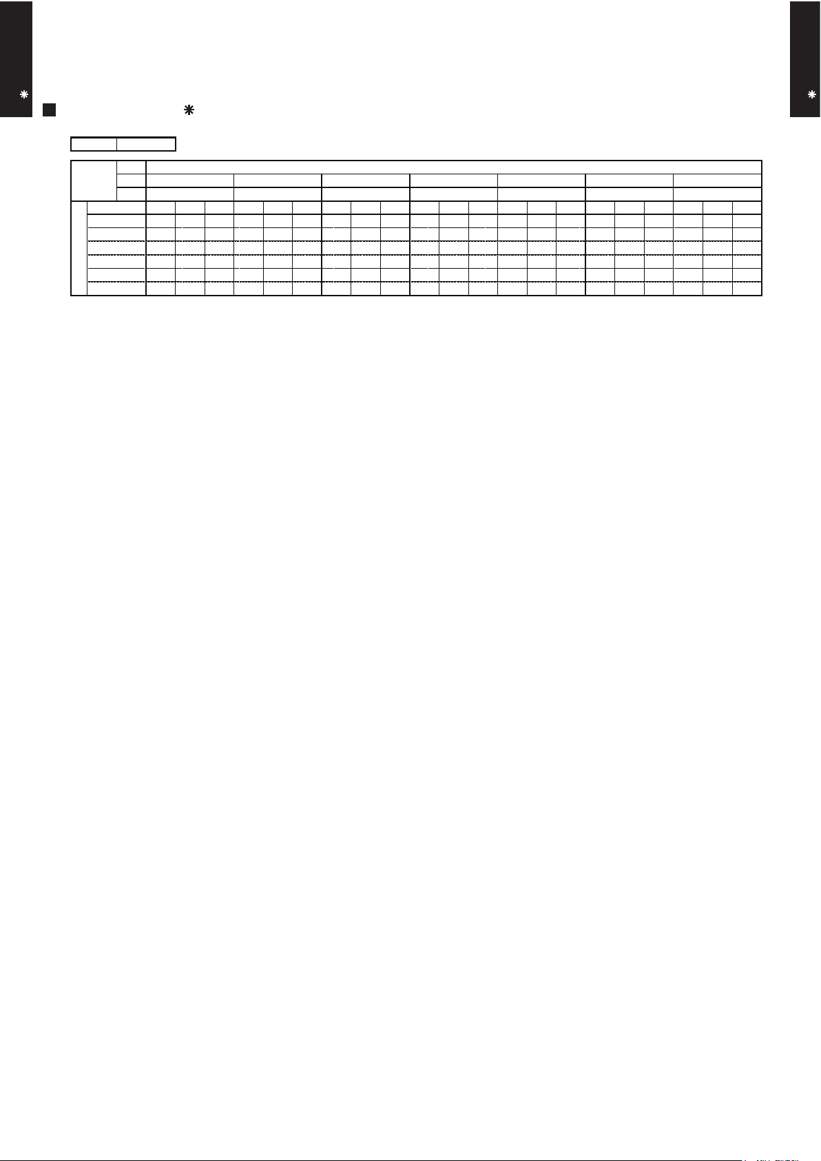
6. CAPACITY TABLE
6-1. COOLING CAPACITY
MODEL : AS B24LD
°CDB
°CWB
TC SHC PI TC SHC PI TC SHC PI TC SHC PI TC SHC PI TC SHC PI TC SHC PI
5.26 4.97 1.05 5.86 5.00 1.07 6.06 5.43 1.07 6.46 5.45 1.09 6.66 5.88 1.09 7.05 5.86 1.10 7.45 6.24 1.11
6.26 5.61 1.75 6.98 5.64 1.78 7.22 6.13 1.79 7.69 6.15 1.80 7.93 6.65 1.81 8.41 6.62 1.83 8.88 7.05 1.85
6.00 5.21 1.94 6.68 5.24 1.97 6.91 5.70 1.98 7.36 5.71 2.00 7.59 6.17 2.01 8.05 6.15 2.03 8.50 6.55 2.05
5.61 4.67 2.13 6.25 4.70 2.17 6.46 5.11 2.18 6.89 5.13 2.20 7.10 5.54 2.21 7.53 5.51 2.23 7.95 5.87 2.25
5.06 4.08 2.15 5.64 4.10 2.18 5.83 4.46 2.19 6.22 4.47 2.21 6.41 4.83 2.22 6.79 4.81 2.25 7.18 5.13 2.27
4.73 3.72 2.16 5.27 3.74 2.20 5.45 4.07 2.21 5.81 4.08 2.23 5.99 4.41 2.24 6.35 4.39 2.27 6.71 4.67 2.29
AFR : Air Flow Rate (m3/min)
TC : Total Capacity (kW)
SHC : Sensible Heat Capacity (kW)
PI : Power Input (kW)
AFR
18.3
43
25
30
35
40
Indoor temperature
Outdoor temperature
12
15
°CDB
20
232518
21
16
18
272932
231921
Page 10

- (01 - 09) -
WALL MOUNTED TYPE
AS B24LD
WALL MOUNTED TYPE
AS B24LD
6-2. HEATING CAPACITY
MODEL : AS B24LD
TC PI TC PI TC PI TC PI TC PI
5.93 2.69 5.78 2.74 5.64 2.80 5.50 2.85 5.36 2.91
7.04 2.94 6.87 3.00 6.70 3.06 6.53 3.12 6.37 3.18
7.92 3.09 7.73 3.15 7.54 3.22 7.36 3.28 7.17 3.34
9.15 3.30 8.94 3.37 8.72 3.43 8.50 3.50 8.28 3.57
10.41 3.52 10.16 3.59 9.91 3.67 9.67 3.74 9.42 3.81
11.13 3.42 10.87 3.49 10.60 3.56 10.34 3.63 10.07 3.70
11.53 3.42 11.25 3.49 10.98 3.56 10.71 3.64 10.43 3.71
11.16 2.97 10.90 3.04 10.63 3.10 10.37 3.16 10.10 3.22
AFR: Air Flow Rate (m3/min)
TC : Total Capacity (kW)
PI : Power Input (kW)
AFR
°CDB
18.3
-16
-11
-7
Outdoor temperature
15
10
60-2
7
385
10
°CDB
°CWB
-15
24
-10
Indoor temperature
-5
161820
22
Page 11

- (01 - 10) -
WALL MOUNTED TYPE
AS B24LD
WALL MOUNTED TYPE
AS B24LD
7. FAN PERFORMANCE
7-1. AIR VELOCITY DISTRIBUTION
MODEL : AS B24LD
Note :
Fan speed : High
Voltage : 230V
Unit : m/s
Unit : m/s
Unit : m/s
Unit : m/s
TOP VIEW
FLOW CONTROL PANEL : Horiz.
LOUVER : Center
TOP VIEW
FLOW CONTROL PANEL : Horiz.
LOUVER : Right & Left
SIDE VIEW
FLOW CONTROL PANEL : Horiz.
LOUVER : Center
SIDE VIEW
FLOW CONTROL PANEL : Vert.
LOUVER : Center
(m)
(m)
(m)
(m)
(m)
(m)
(m)
(m)
Operation mode :FAN
1
765
43
2 8
1 765432 8
-3
-2
-1
0
1
2
3
-2
-1
0
1
2
0
1
2
3
1
765
43
2 8
0
1
2
3
1
765
43
2 8
2.0 1.0 0.5
1.0
0.5
0.5
2.0
1.0
2.0
1.0
0.5
2.0
1.0
0.5
Page 12

- (01 - 11) -
WALL MOUNTED TYPE
AS B24LD
WALL MOUNTED TYPE
AS B24LD
MODEL : AS B24LD
COOLING
7-2. AIR FLOW
HEATING
1170
m3/h
325 l/s
689 CFM
970
m3/h
269 l/s
571 CFM
785
m3/h
218 l/s
462 CFM
685
m3/h
190 l/s
403 CFM
1380
1170
980
860
HIGH
MED
LOW
QUIET
Air flow
Fan speed
Number of
rotations
(r.p.m)
1170
m3/h
325 l/s
689 CFM
970
m3/h
269 l/s
571 CFM
785
m3/h
218 l/s
462 CFM
685
m3/h
190 l/s
403 CFM
LOW
980
860
QUIET
HIGH
1380
1170
MED
Air flow
Fan speed
Number of
rotations
(r.p.m)
Page 13

- (01 - 12) -
WALL MOUNTED TYPE
AS B24LD
WALL MOUNTED TYPE
AS B24LD
High
Quiet
8-1. NOISE LEVEL CURVE
8. OPERATION NOISE
MODEL : AS B24LD
Octave band sound pressure level, dB:(0dB=0.0002µbar)
Octave band center frequency,Hz
0
10
20
30
40
50
60
70
80
Octave band sound pressure level, dB:(0dB=0.0002µbar)
Octave band center frequency,Hz
0
10
20
30
40
50
60
70
80
63 125 250 500 1,000 2,000 4,000 8,000
63 125 250 500 1,000 2,000 4,000 8,000
MODEL : AS B24LD
COOLING
HEATING
High
Quiet
NC-20
NC-40
NC-50
NC-60
NC-30
NC-15
NC-25
NC-35
NC-45
NC-55
NC-65
NC-20
NC-40
NC-50
NC-60
NC-30
NC-15
NC-25
NC-35
NC-45
NC-55
NC-65
Page 14

- (01 - 13) -
WALL MOUNTED TYPE
AS B24LD
WALL MOUNTED TYPE
AS B24LD
8-2.
SOUND LEVEL CHECK POINT
Page 15

- (01 - 14) -
WALL MOUNTED TYPE
AS B24LD
WALL MOUNTED TYPE
AS B24LD
9. ELECTRIC CHARACTERISTICS
Model Name AS B24LD
Voltage V 230
Frequency Hz 50
Max Operating Current A 0.3
Circuit breaker A 0.4
Connection Cable
mm
2
1.5 - 2.5
Limited wiring length m 31
*1) Wiring Spec.
Selected Sample
(Selected based on Japan Electrotechnical Standard and Codes Committee E0005)
*1)Wiring Spec.
Power Supply
Page 16

- (01 - 15) -
WALL MOUNTED TYPE
AS B24LD
WALL MOUNTED TYPE
AS B24LD
10. SAFETY DEVICES
Model
AS B24LD
Circuit protection Current fuse (PCB) 3.15A 250V
Terminal protection Current fuse 3A 250V
Fan motor protection Thermal protection program
100
+15
-10
°C OFF
95
+5
-10
°C ON
Protection form
Page 17

11. OPTIONAL PARTS
WALL MOUNTED TYPE
AS B24LD
Exterior Summary
SUMOTUWETH FR
SA
AM
PM
3 6 9
12 15 18 21
Parts name
Wired remote
controller
Air-cleaning and
deodorizing filter
Model No.
UTB-UD
UTR-FA14
Unit control is performed by
wired remote controller
Negatively-charged dust, etc.
are attracted to the earth
section and are collected by a
bacteria eliminating &
deodorizing filter.
WALL MOUNTED TYPE
AS B24LD
External
connect kit
UTY-XWZX
Use to connect with various
peripheral devices and air
conditioner PC board.
- (01 - 16) -
Page 18

- (01 - 17) -
WALL MOUNTED TYPE
AS B24LD
WALL MOUNTED TYPE
AS B24LD
11-1. WIRED REMOTE CONTROLLER
FEATURES
Simple function setting
Setting of the air conditioner selection function is performed by remote controller.
High performance and compact size
Various timer setup (ON / OFF / WEEKLY) are possible.
Equipped with weekly timer as standard function.
(2 times Start / Stop per day for a week)
When setting up a timer, operation mode and a temperature
setup can be changed.
When a failure occurs,the error code is displayed.
Error indication.
Easy installation with a slim shape with no bulge in the back.
Three functions are combined in
one unit.
Wired
remote
controller
Built-in timers
Possible to set ON/OFF time to operate twice each day
of the week.
SUMOTUWETH FR SA
7
Setup screen example
(Set to Wednesday: 8:00 to 20:00.)
3126 9
15 18 21
0 3 6 9 12 15 18 21 Time
At "Weekly timer" + "Set back timer" setup
Easy-to-understand time bar display
SUMOTUWETH FR SA
7
3126 9
15 18 21
24°C
24°C 28°C 24°C
Weekly
timer
Setback
timer
Setback timerWeekly timer
Possible to set temperature for two time spans and
for each day of the week.
SUMOTUWETH FR SA
Screen
after setup
Setup screen example
(Set from Sunday to Saturday: 12:00 to 15:00, 28 °C.)
0 3 6 9 12 15 18 21 Time
24°C
0 3 6 9 12 15 18 21 Time
28°C
3126 9
15 18 21
28°C
Easy-to-understand operation Simple installation
Components are compatible with standard
switch boxes. Flat back construction allows
equipment to be installed wherever it is
needed.
Timer
area
[
Variable timer control
]
The operation/display sections are zoned according to time and operation, enabling variable programming to match application.
Operation
area
European
switch box
JIS box
Page 19
- (01 - 18) -
WALL MOUNTED TYPE
AS B24LD
WALL MOUNTED TYPE
AS B24LD
FUNCTIONS
2
6
7
8
9
10
11
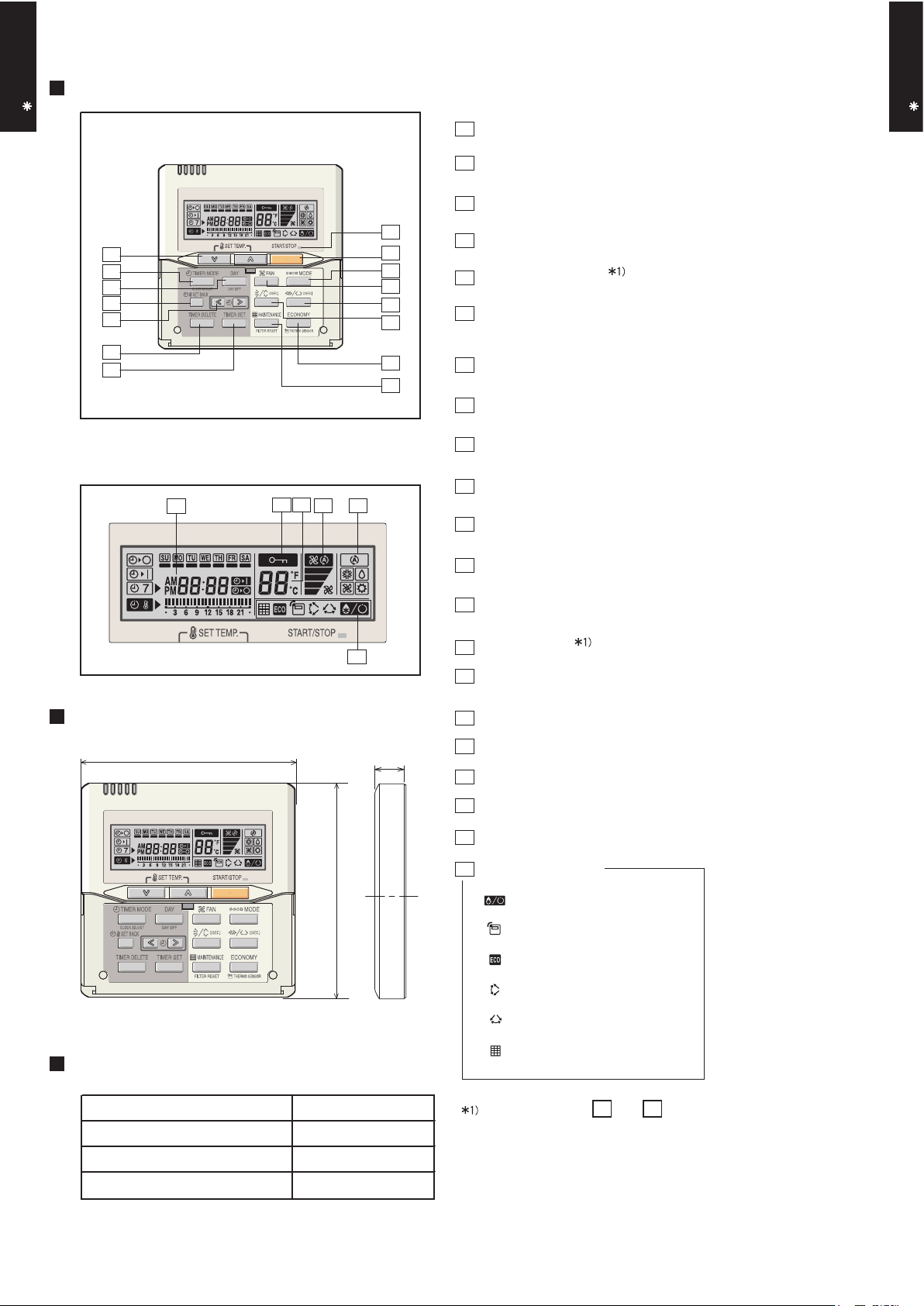
Display panel
16
19
20
18
17
15
13
12
14
1
START/STOP button
Pressed to start and stop operation.
2
Set temperature button
Selects the setting temperature.
3
Master control button
Selects the operating mode(AUTO, HEAT, FAN, COOL, DRY).
4
1
3
4
5
Fan control button
Selects the fan speed (AUTO, QUIET, LOW, MED, HIGH).
5
Economy button
Turns the economy efficient mode on and off.
6
Timer mode (CLOCK ADJUST) button
Selects the timer mode (OFF TIMER, ON TIMER, WEEKLY TIMER)
Set the current time.
7
Day (DAY OFF) button
Temporarily cancels of one day timer.
8
Set back button
Pressed to select the set back timer.
9
Set time button
Pressed to set time.
10
Delete button
The schedule of a weekly timer is deleted.
11
Set button
Sets the date, hour, minute and on-off time.
12
Vertical airflow direction and swing button
Push for two seconds to change the swing mode.
13
Horizontal airflow direction and swing button
Push for two seconds to change the swing mode.
DIMENSION
120
Front View
SPECIFICATION
21
[ Unit : mm ]
120
14
Filter button
15
Operation lamp
Lights during operation and when the timer is on.
16
Timer and clock display
17
17
Operation mode display
18
Fan speed display
19
Operation lock display
20
Temperature display
21
Function display
Defrost display
Thermo sensor display
Economy display
Vertical swing display
Horizontal sw
ing display
Filter display
SIZE (H x W x D mm) 120 x 120 x 17
WEIGHT ( g ) 160
CABLE LENGTH ( m )
POWER ( V )
10
12
Button number 5 and
can not be operated.
14
Page 20
- (01 - 19) -
WALL MOUNTED TYPE
AS B24LD
WALL MOUNTED TYPE
AS B24LD
11-2. EXTERNAL CONNECT KIT
This kit allows to operate the air conditioner, such as stopping and starting, using an external
device, and output the operation status of the air conditioner.
• Only operation and stop signals will be output.
Use the remote control to check the operation mode, temperature, and airflow.
Check the error information on the display area of the main unit.
• Operation mode, temperature, and airflow cannot be set by external input. Use the remote
controller to set.
• If the air-conditioner is activated by external input, it will operate in the settings before stop.
To change the settings, use the remote controller.
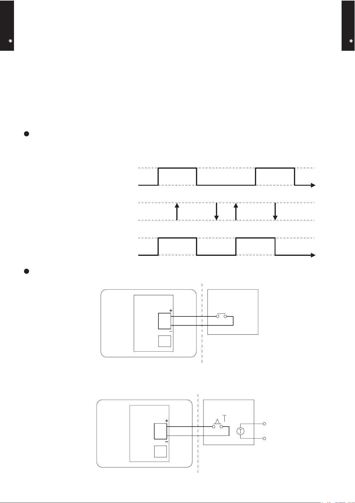
11-2-1. CONTROL INPUT SETTING
• You can control air conditioner ON / OFF operation by external input.
Signal specification
• No voltage ON/OFF continuous signal.
• Contact capacity : DC12V 10mA
External input signal
ON
OFF
Remote controller signal
OPERATION
Indoor unit status
Installation example
• For remote operation
Indoor unit External device
• For external timer operation
STOP
Print circuit
board
External
input
External
output
ON ONOFF OFF
( Field supply )
Orange
1
Yellow
3
Indoor unit External device
Print circuit
board
External
input
External
output
Orange
1
Yellow
3
( Field supply )
Page 21
- (01 - 20) -
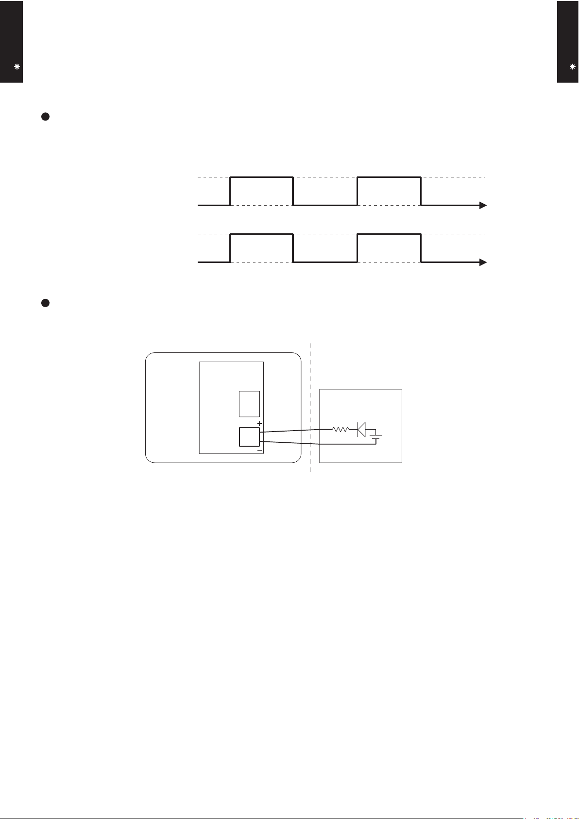
For operation display
• No voltage contact.
• Contact capacity : Max. DC24V 10mA to 1A or less
SHORT
External output signal
Indoor unit status
OPEN
OPERATION
STOP
Installation example
Blue
External
input
Vc
Ic
External
output
1
2
Purple
Indoor unit
External device
( Field supply )
Print circuit
board
11-2-2. Operating output setting
• You can display air conditioner ON / OFF operation by external output.
Signal specification
WALL MOUNTED TYPE
AS B24LD
WALL MOUNTED TYPE
AS B24LD
Page 22

R410A
D1D_AO004E/02
2009.03.04
2. SINGLE
TYPE :
AO S24LDC
OUTDOOR UNIT
Page 23
- (02 - 01) -
OUTDOOR UNIT
AO S24LD
OUTDOOR UNIT
AO S24LD
1. SPECIFICATIONS
INVERTER HEAT PUMP
AO S24LDC
230V 50Hz
198-264V 50Hz
A 9.8
2,340
2,470
Propeller fan × 1
W 65
52
54
Main : 546 × 866 × 36.4
Sub : 504 × 589 × 18.2
Main : 1.4, Sub : 1.4
Main : 2 × 26, Sub : 1 × 24
Copper
Aluminium
Scroll × 1
W 1,200
R410A
g 1,600
PVE (FV50S)
Steel
Beige
578 × 790 × 315
648 × 910 × 380
44 (97)
48 (105.8)
6.35 ( 1/4 in.)
15.88 ( 5/8 in.)
Flare
30 (chargeless : 15)
20
-10 to 43
-15 to 24
Note :
Specifications are based on the following conditions.
Cooling : Indoor temperature of 27°CDB/19°CWB. and outdoor temperature of 35°CDB/24°CWB.
Heating : Indoor temperature of 20°CDB/15°CWB. and outdoor temperature of 7°CDB/6°CWB.
Pipe length : 7.5 m, Height difference : 0 m. (Outdoor unit - Indoor unit)
Cooling
Heating
Colour
Net
Gross
Net
Type
Charge
Type
Material
Motor output
Cooling
Heating
Dimensions (H × W × D)
Type
Model name
Power source
Available voltage range
°C
Operation range
Fan
Airflow
rate
m3/h
dB(A)
mm
mm
Weight
kg(lb.)
Dimensions
(H × W × D)
Gross
Refrigerant oil
Enclosure
Heat exchanger type
Fin pitch
Rows × Stages
Pipe type
Fin type
Type × Q'ty
Motor output
Compressor
Refrigerant
Sound pressure level
Starting current
Cooling
Heating
Type × Q'ty
m
Connection pipe
Size
mm
Liquid
Gas
Method
Max. length
Max. height difference
Page 24

- (02 - 02) -
OUTDOOR UNIT
AO S24LD
OUTDOOR UNIT
AO S24LD
2. DIMENSIONS
MODEL : AO S24LD
(Unit : mm)
Air flow
Top view
Front view
Side view
Bottom view
600 mm or more
100 mm or more
300 mm or more
100 mm or more
300 mm or more
(Service space)
MOUNTING POSITION
If the space is larger that is stated, the condition will be the same as that are no obstacles.
Page 25
- (02 - 03) -
OUTDOOR UNIT
AO S24LD
OUTDOOR UNIT
AO S24LD
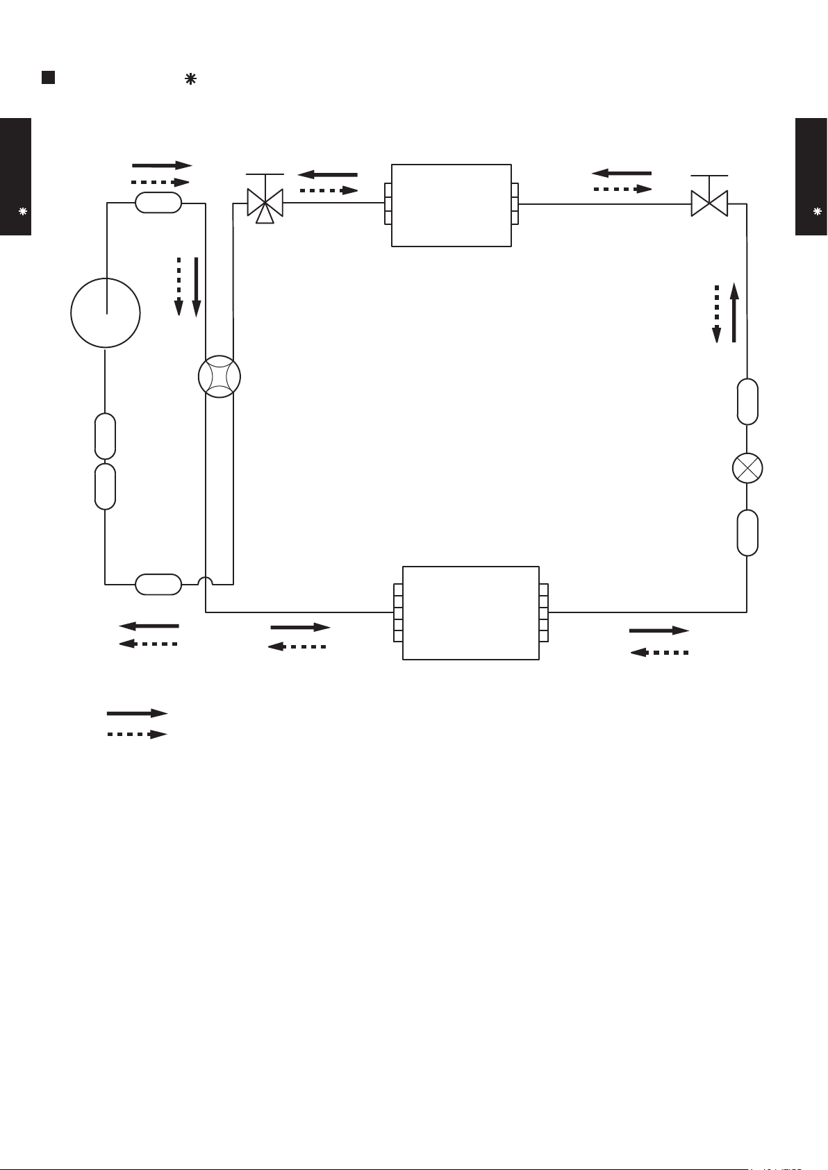
MODEL : AO S24LD
3. REFRIGERANT CIRCUIT
2-Way
valve
Strainer
Strainer
Strainer
3-Way
valve
Muffler
4-Way valve
Expansion valve
Heat exchanger
( INDOOR )
Heat exchanger
( OUTDOOR )
Sub-accumulator
Compressor
Cooling
Heating
Refrigerant pipe diameter
Liquid : 1/4" (6.35 mm)
Gas : 5/8" (15.88 mm)
Page 26

- (02 - 04) -
OUTDOOR UNIT
AO S24LD
OUTDOOR UNIT
AO S24LD
MODEL : AO S24LD
4. WIRING DIAGRAMS
TO INDOOR
UNIT
TO POWER
SUPPLY
Page 27

- (02 - 05) -
OUTDOOR UNIT
AO S24LD
OUTDOOR UNIT
AO S24LD
5. COEFFICIENT OF COMPENSATION FOR PIPE LENGTH
AND HEIGHT DIFFERENCE
MODEL : AO S24LD
Indoor unit
Height difference H
Connection pipe
H
Outdoor unit
Indoor unit
Connection pipe
H
Outdoor unit
Indoor unit is upper than outdoor unit.
1
Indoor unit is under than outdoor unit.
2
5 7.5 10 15 20 25 30
20 - - - 0.951 0.952 0.951 0.951
10 - - 0.980 0.966 0.968 0.967 0.966
7.5 - 0.988 0.984 0.970 0.972 0.971 0.970
5 0.995 0.992 0.988 0.974 0.976 0.975 0.974
0 1.003 1.000 0.996 0.982 0.983 0.983 0.982
-5 1.003 1.000 0.996 0.982 0.983 0.983 0.982
-7.5 - 1.000 0.996 0.982 0.983 0.983 0.982
-10 - - 0.996 0.982 0.983 0.983 0.982
-20 - - - 0.982 0.983 0.983 0.982
COOLING
*1
Indoor unit is
upper than outdoor
unit.
*2
Indoor unit is
under than outdoor
unit
Height
difference H
(m)
Pipe length (m)
5 7.5 10 15 20 25 30
20 - - - 0.975 0.954 0.932 0.908
10 - - 0.998 0.975 0.954 0.932 0.908
7.5 - 1.000 0.998 0.975 0.954 0.932 0.908
5 0.989 1.000 0.998 0.975 0.954 0.932 0.908
0 0.989 1.000 0.998 0.975 0.954 0.932 0.908
-5 0.984 0.995 0.993 0.970 0.950 0.927 0.903
-7.5 - 0.993 0.991 0.968 0.947 0.925 0.901
-10 - - 0.988 0.965 0.945 0.923 0.899
-20 - - - 0.956 0.935 0.914 0.890
HEATING
Pipe length (m)
Height
difference H
(m)
*1
Indoor unit is
upper than outdoor
unit.
*2
Indoor unit is
under than outdoor
unit
Page 28

- (02 - 06) -
OUTDOOR UNIT
AO S24LD
OUTDOOR UNIT
AO S24LD
6. ADDITIONAL CHARGE CALCULATION
MODEL : AO S24LD
REFRIGERANT CHARGE
Refrigerant type
Refrigerant amount g
Pipe length m 15 20 25 30
Additional charge g 0 (Chargeless) +100 +200 +300
R410A
20g/m
1600
Page 29

- (02 - 07) -
OUTDOOR UNIT
AO S24LD
OUTDOOR UNIT
AO S24LD
MODEL : AO S24LD
7. AIR FLOW
COOLING
HEATING
m3/h
2340
l/s650
CFM1377
Air flow
Number of
rotations
(r.p.m)
1000
m3/h
2470
l/s686
CFM1454
1050
Air flow
Number of
rotations
(r.p.m)
Page 30

- (02 - 08) -
OUTDOOR UNIT
AO S24LD
OUTDOOR UNIT
AO S24LD
8-1. NOISE LEVEL CURVE
MODEL : AO S24LD
Octave band sound pressure level, dB:(0dB=0.0002µbar)
Octave band center frequency,Hz
0
10
20
30
40
50
60
70
80
63 125 250 500 1,000 2,000 4,000 8,000
8. OPERATION NOISE
COOLING
Octave band sound pressure level, dB:(0dB=0.0002µbar)
Octave band center frequency,Hz
0
10
20
30
40
50
60
70
80
63 125 250 500 1,000 2,000 4,000 8,000
MODEL : AO S24LD
HEATING
NC-20
NC-40
NC-50
NC-60
NC-30
NC-15
NC-25
NC-35
NC-45
NC-55
NC-65
NC-20
NC-40
NC-50
NC-60
NC-30
NC-15
NC-25
NC-35
NC-45
NC-55
NC-65
Page 31

- (02 - 09) -
OUTDOOR UNIT
AO S24LD
OUTDOOR UNIT
AO S24LD
8-2. SOUND LEVEL CHECK POINT
Page 32
- (02 - 10) -
OUTDOOR UNIT
AO S24LD
OUTDOOR UNIT
AO S24LD
9. ELECTRIC CHARACTERISTICS
AO S24LD
Voltage V
Frequency Hz
Max Operating Current A 17.5
A 9.8
Main Fuse (Circuit breaker)
Current
A 30
Power Cable
mm
2
3.5 - 4.5
*2)Limited wiring length m 20
*1) Wiring Spec.
Selected Sample
(Selected based on Japan Electrotechnical Standard and Codes Committee E0005)
*2) Limited Wiring length :
This is the wiring length in case voltage descent is less than 2%.
When the wiring length becomes long, please select the wiring of a more larger diameter.
Model Name
Starting Current
Power Supply
*1) Wiring Spec.
230
50
Page 33
- (02 - 11) -
OUTDOOR UNIT
AO S24LD
OUTDOOR UNIT
AO S24LD
10. SAFETY DEVICES
AO S24LD
20A 250V
5A 250V
15A 250V
3.15A 250V
Fan motor protection
Thermal protection program
OFF : 110
+15
-10
°C
ON : 105
+15
-10
°C
Thermal protection program
(DISCHARGE TEMP.)
OFF : 110°C
ON : After 7 minutes
Protection form
Model
Circuit protection
Current fuse (NEAR THE
TERMINAL)
Current fuse
(MAIN PRINTED CIRCUIT BOARD)
Compressor protection
 Loading...