

Fujitsu AS*A24LCC, AS*A30LCC, AS*A30LFC, AO*R24LCC, AO*R30LCT Design & Technical Manual
...Page 1
AIR CONDITIONER
Wall Mounted type
DESIGN & TECHNICAL MANUAL
INDOOR
OUTDOOR
ASÜA24LCC
ASÜA30LCC
ASÜA30LFC
AOÜR24LCC
AOÜR30LCT
AOÜR30LFT
Page 2

1. INDOOR UNIT
WALL MOUNTED TYPE :
ASÝA24LCC
ASÝA30LCC
ASÝA30LFC
D1D_AS001E/04
2010.02.10
Page 3

A24-30LC(F)
Ü
WALL MOUNTED TYPE
AS
CONTENTS
A24-30LC(F)
Ü
WALL MOUNTED TYPE
AS
1. INDOOR UNIT
1. FEATURE
.................................................................................................................. 01 - 01
2. WIRELESS REMOTE CONTROLLER
3. SPECIFICATIONS
4. DIMENSIONS
5. WIRING DIAGRAMS
6. CAPACITY TABLE
6-1. COOLING CAPACITY
6-2. HEATING CAPACITY
7. FAN PERFORMANCE
7-1. AIR VELOCITY DISTRIBUTION
7-2. AIR FLOW
.......................................................................................................... 01 - 13
8. OPERATION NOISE
8-1. NOISE LEVEL CURVE
.............................................................................................. 01 - 05
........................................................................................................ 01 - 07
........................................................................................ 01 - 08
............................................................................................ 01 - 10
...................................................................................... 01 - 10
........................................................................................01 - 11
.................................................................................... 01 - 12
..................................................................... 01 - 12
......................................................................................... 01 - 16
.................................................................................... 01 - 16
............................................... 01 - 03
8-2. SOUND LEVEL CHECK POINT
..................................................................... 01 - 18
9. ELECTRIC CHARACTERISTICS
10. SAFETY DEVICES
11. OPTIONAL PARTS
11-1. WIRED REMOTE CONTROLLER
11-2. EXTERNAL CONNECT KIT
............................................................................................ 01 - 20
........................................................................................... 01 - 21
.................................................................. 01 - 22
............................................................................ 01 - 24
........................................................... 01 - 19
Page 4

FEATURE1.
Front view
b
a
c
Large air flow and quiet
operation by new air
flow path
High efficiency
layout
Back view
New 3-row heat
exchange system
(24TYPE)
1
2
3
V-PAM technology makes a compressor more powerful.
V P
More compact compared with conventional model
Heat exchange capacities 20% up
compared to conventional models
V-P
V-PAM control
b
DC
scroll compressor
c
a
DC
fan motor
DC fan motor
During dew
condensation
Approx. 20 mins
Drying
MODEL
A24-30LC(F)
Ü
WALL MOUNTED TYPE
AS
ASÜA24LCC
ASÜA30LCC
ASÜA30LFC
A24-30LC(F)
Ü
WALL MOUNTED TYPE
AS
FEATURES
ALL DC
z
Super quiet
z
AOÜR24LCC
AOÜR30LCT
AOÜR30LFT
Air ow mode can be set in 4 steps and more detailed air ow setting is possible.
Easy maintenance
z
Easy maintenance and always clean. Troublesome maintenance has been made easy.
Since the front panel is easy to remove, maintenance is also easy.
Inner drying operation
z
This model is equipped with an inner drying function. After the power is turned off, the dry
operation starts inside the air conditioner. This prevents the growth of mold and bacterial inside
the air conditioner.
- (01 - 01) -
Page 5

Power diffuser
2.52.5
5
0 3 6 9 12(m)
Outside air conditions: 2 oC 60%
( C)
Operation contents: Heating,
Set temperature (Max set temp)
30
o
o
C, Air flow Hi,
Air direction downward and front
Power diffuser
(full open)
2933 32 31 30
2.5
46
o
Power diffuser
5
2.5
0 3 6 9 12(m)
Outside air conditions: 35 oC 40%
( C)
Operation contents: Cooling,
Set temperature (Min set temp)
18
o
o
C, Air flow Hi,
Air direction downward and front
1815 16 17
Organic coating fin used
heat exchanger
Pre Filter
Antibacterial deodorizing
pre-filter with special
ceramic powder
Ion Deodorization Filter
Apple-catechin Filter
Applecatechin Filter
Long-life Ion
Deodorization Filter
A24-30LC(F)
Ü
WALL MOUNTED TYPE
AS
z
Adoption of large power diffuser
“Strong vertical air ow” provides
powerful oor level heating.
Compact design
z
“Healthy horizontal air ow” does not blow
cool air directly at the occupants in the room.
A24-30LC(F)
Ü
WALL MOUNTED TYPE
AS
998mm width compact design
New model
Low outdoor air temperature cooling correspondence
z
Corresponds to cooling operation at -10°C outdoor air temperature
Corresponds to maximum 50m long piping (30TYPE)
z
Air conditioner lter features
z
H320 x W998 x D228 H320 x W1,120 x D220
(unit:mm)
- (01 - 02) -
Page 6

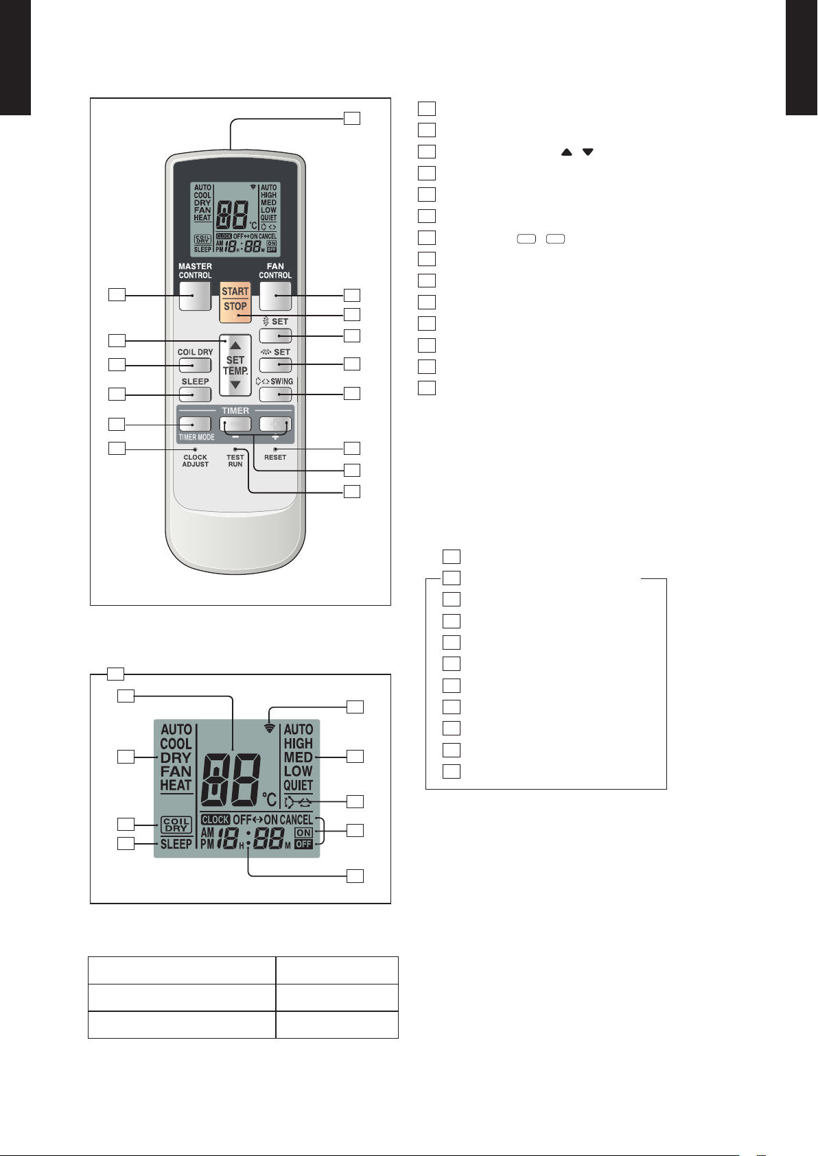
WIRELESS REMOTE CONTROLLER2.
60min.
1 °C
2 °C
Timer setting
1 °C
30min.
60min.
90min.
2 °C
3 °C
4 °C
Timer setting
FEATURES
A24-30LC(F)
Ü
WALL MOUNTED TYPE
AS
Four kinds of timer setup
Ü
(ON / OFF / PROGRAM / SLEEP) are possible.
Four kinds of timers. Easy operation.
Ü
Built-in timers
z
Select from four different timer programs (On/Off/Program/Sleep).
Program timer
z
The program timer operates the ON and OFF timer once within a 24 hour period.
Sleep timer
z
The sleep timer function automatically corrects the temperature thermostat setting according to
the time setting to prevent excessive cooling and heating while sleeping.
A24-30LC(F)
Ü
WALL MOUNTED TYPE
AS
Cooling operation/dry operation
When the sleep timer is set, the set temperature
automatically rises 1 °C every hour. The set
temperature can rise up to a maximum of 2 °C.
Heating operation
When the sleep timer is set, the set temperature
automatically drops 1 °C every 30 minutes. The set
temperature can drop to a maximum of 4 °C.
- (01 - 03) -
Page 7
A24-30LC(F)
2
4
9
3
1
15
5
10
13
11
12
14
8
7
6
17
18
19
21
24
23
22
25
20
16
Ü
WALL MOUNTED TYPE
AS
FUNCTIONS
1
SLEEP button
2
MODE button
3
SET TEMP. button ( / )
4
COIL DRY button
5
Signal Transmitter
6
TIMER MODE button
7
TIMER SET (+ / -) button
8
FAN CONTROL button
9
START/STOP button
10
SET button (Vertical)
11
SET button (Horizontal)
12
SWING button
13
RESET button
14
TEST RUN button
•This button is used when installing the air conditioner, and should
not be used under normal conditions, as it will cause the indoor
unit’s thermostat function to operate incorrectly.
•If this button is pressed during normal operation, the indoor
unit will switch to test operation mode, and the Indoor Unit’s
OPERATION Indicator Lamp and TIMER Indicator Lamp will
begin to ash simultaneously.
•To stop the test operation mode, press the SR ART/STOP but ton
to stop the air conditioner.
A24-30LC(F)
Ü
WALL MOUNTED TYPE
AS
15
CLOCK ADJUST button
16
Remote Control Unit Display
17
Transmit Indicator
18
Clock Display
19
Display panel
SPECIFICATION
SIZE (H x W x D mm) 176 x 56 x 18
Operating Mode Display
20
Timer Mode Display
21
Fan Speed Display
22
Temperature SET Display
23
COIL DRY Display
24
SLEEP Display
25
SWING Display
WEIGHT ( g ) 110
ACCESSORY Holder
- (01 - 04) -
Page 8

SPECIFICATIONS3.
A24-30LC(F)
Ü
WALL MOUNTED TYPE
AS
Typ e
Model name ASÜA24LCC ASÜA30LCC
Power source 230V~ 50Hz
Available voltage range 198 - 264V ~ 50Hz
ENERGY STAR RANK
Cooling
Capacity
Heating
Input power
Current
EER Cooling
COP Heating 3.62 3. 41
SENSIBLE CAPACIT Y Cooling kW 5.54 5.34
POWER FACTOR
Moisture removal l/h (pints/h) 3.0(5.3) 3.4(6.0)
Fan
Sound pressure level
Heat exchanger type
Enclosure
Dimensions
( H×W ×D )
Weight
Connection pipe
Operation range
Remote controller type Wireless
Drain pipe
Note :
Specications are based on the following conditions.
Cooling : Indoor temperature of 27°CD B/19°CWB. and outdoor temperature of 35°CDB/24°CWB.
Heating : Indoor temperature of 20°CDB/15°CWB. and outdoor temperature of 7°CDB/6°CWBA.
Pipe length : 7.5 m, Height dif ferenc e : 0 m.(Outdoor unit - Indoor unit)
The maximum current is the maximum value when operated within the operation range(temperature)
* The maximum current is the total current of indoor unit and outdoor unit.
Cooling
Heating
Cooling
Heating
Airow
rate
Type × Q'ty Cross ow fan × 1
Motor output W 42 42
Net
Gross 319 × 1090 × 429
Net
Gross 18 (39.6)
Size
Method Flare
Material PVC
Size mm Outer diameter: 28 / Inner diameter: 16
Rated
Min.-Max.
Rated
Min.-Max.
Rated
Min.-Max. 0.11 -2 .62 0.58-3.60
Rated 2.24 2.64
Min.-Max. 0.11 -3 .68 0.50-4.30
Rated
Max.* 12 17
Rated 9.8 11.6
Max.* 17. 5 19
Cooling
Heating 99 99
Cooling
Heating
Cooling
Heating
Dimensions
(H × W × D)
Fin pitch Main : 1.2, Sub : 1.4 Main : 1.2, Sub1 : 1.4, Sub2 : 1.4
Rows x Stages Main : 2 × 18, Sub : 1 × 4
Pipe type Copper
Fin type Aluminium
Material Polystyrene
Colour
Liquid
Gas Ø15.88 (Ø 5/8 in.)
Cooling
Heating °C 30 or less
Cooling A B
Heating A B
kW 7.10 8.00
BTU/h 24,200 27, 3 00
kW 0.9-8.0 2.9-9.0
BTU/h 3,100-27,300 9,900-30,700
kW 8.10 9.00
BTU/h 2 7,6 00 30,70 0
kW 0.9-10.6 2. 2-11 .0
BTU/h 3,100-36,200 7, 50 0- 37,6 0 0
kW
A
kW/kW
%
High
Med 900 900
Low 740 740
Quiet 620 620
High 110 0 110 0
Med 900 900
Low 740 740
Quiet 620 620
High
Med 41 41
Low 36 36
Quiet 32 32
High 45 45
Med 36 36
Low 32 32
Quiet 32 32
3
/h
m
dB(A)
mm
mm
kg(lb.)
mm
°C 18 to 32
%RH 80 or less
Main : 378 × 832 × 26.6
2.21 2.66
9.7 11.7
3.21 3.01
99 99
110 0 110 0
47 47
Sub : 84 × 832 × 13.3
Approximate colour of MANSELL N9.25/
Ø6.35 (Ø 1/4 in.) Ø9.52 (Ø 3/8 in.)
WALL MOUNTED
INVERTER HEAT PUMP
Main : 378 × 832 × 26.6
Sub1 : 84 × 832 × 13.3,
Sub2 : 84 × 832 × 13.3
Main : 2 × 18,
Sub : 1 × 4,
Sub2 : 1 × 4
WHITE
320 × 998 × 228
14 (30.8)
A24-30LC(F)
Ü
WALL MOUNTED TYPE
AS
- (01 - 05) -
Page 9

A24-30LC(F)
Ü
WALL MOUNTED TYPE
AS
Typ e
Model name ASÜA30LFC
Power source 230V~ 50Hz
Available voltage range 198-26 4V ~ 50Hz
European energy label
Cooling
Capacity
Heating
Input power
Current
EER Cooling
COP Heating 3.61
SENSIBLE CAPACIT Y Cooling kW 6.00
POWER FACTOR
Moisture removal l/h (pints/h) 3.2 (5.6)
Fan
Sound pressure level
Heat exchanger type
Enclosure
Dimensions
( H×W ×D )
Weight
Connection pipe
Operation range
Remote controller type Wireless
Drain pipe
Cooling
Heating
Cooling
Heating
Airow
rate
Type × Q'ty Cross ow fan×1
Motor output W 42
Net
Gross 319×1090× 429
Net
Gross 18 (39.6 )
Size
Method Flare
Material PVC
Size mm Outer diameter: 28 / Inner diameter: 16
Rated
Min-Max
Rated
Min-Max
Rated
Min-Max 0.58-3.87
Rated 2.44
Min-Max 0.50- 4.33
Rated
Max 17. 0
Rated 10.7
Max 19.0
Cooling
Heating 99
High
Cooling
Heating
Cooling
Heating
Dimensions
(H × W × D)
Fin pitch Main:1.2, Sub1:1.4, Sub2:1.4
Rows x Stages Main:2×18, Sub:1×4, Sub2:1×4
Pipe type Copper
Fin type Aluminium
Material Polystyrene
Colour
Liquid
Gas Ø15.88 (Ø5 /8 in.)
Cooling
Heating °C 30 or less
Med 900
Low 740
Quiet 620
High 1150
Med 900
Low 740
Quiet 620
High
Med 42
Low 37
Quiet 33
High 49
Med 42
Low 37
Quiet 33
Cooling A
Heating A
kW 8.00
BTU/h 2 7,3 0 0
kW 2.9-9.0
BTU/h 9,900-30,700
kW 8.80
BTU/h 30,000
kW 2 .2- 11.0
BTU/h 7, 5 00 - 37,6 0 0
kW
A
kW/kW
%
3
/h
m
dB(A)
mm
mm
kg(lb.)
mm
°C 18 to 32
%RH 80 or less
Sub1:84×832×13.3 ,Sub2:84×832×13.3
Approximate colour of MANSELL N9.25/
WALL MOUNTED
INVERTER HEAT PUMP
2.49
10.9
3.21
99
1100
48
Main:378×832×26.6
WHITE
320×998×228
14 (30.8 )
Ø9.52 (Ø3/8 in.)
A24-30LC(F)
Ü
WALL MOUNTED TYPE
AS
Note :
Specications are based on the following conditions.
Cooling : Indoor temperature of 27°CD B/19°CWB. and outdoor temperature of 35°CDB/24°CWB.
Heating : Indoor temperature of 20°CDB/15°CWB. and outdoor temperature of 7°CDB/6°CWBA.
Pipe length : 7.5 m, Height dif ferenc e : 0 m.(Outdoor unit - Indoor unit)
The maximum current is the maximum value when operated within the opration range(temperature)
* The maximum current is the total current of indoor unit and outdoor unit.
- (01 - 06) -
Page 10

DIMENSIONS4.
Wall hook bracket
6 cm or more
150 cm or more
(Wall cap)
230 cm or more
5 cm or more
5 cm or more
Wall hook bracket
6 cm or more
150 cm or more
(Wall cap)
180 cm or more
5 cm or more
5 cm or more
998
228
320
A24-30LC(F)
Ü
WALL MOUNTED TYPE
AS
MODEL : ASÜA24LC, ASÜA30LC, ASÜA30LF
INSTALLATION PLACE
Model : AS
z
A24LC, ASÜA30LC
Ü
(Unit : mm)
A24-30LC(F)
Ü
WALL MOUNTED TYPE
AS
Model : AS
z
A30LF
Ü
- (01 - 07) -
Page 11

WIRING DIAGRAMS5.
TO OUTDOOR UNIT
A24-30LC(F)
Ü
WALL MOUNTED TYPE
AS
MODEL : ASÜA24LC, ASÜA30LC
A24-30LC(F)
Ü
WALL MOUNTED TYPE
AS
- (01 - 08) -
Page 12

A24-30LC(F)
TO OUTDOOR UNIT
CONTROOL BOARD
TEST
CN13
CN14
2
1
CN16
EX.OUT
(OPTION)
EX.IN
(OPTION)
1
2
3
BLACK
WHITE
RED
REMOTE CONTROL
UNIT (OPTION)
3
2
1
Ü
WALL MOUNTED TYPE
AS
MODEL : ASÜA30LF
A24-30LC(F)
Ü
WALL MOUNTED TYPE
AS
- (01 - 09) -
Page 13

CAPACITY TABLE6.
A24-30LC(F)
Ü
WALL MOUNTED TYPE
AS
COOLING CAPACITY6-1.
MODEL : ASÜA24LC
AFR 18.3
°CDB 18 21 23 25 27 29 32
°CWB 12 15 16 18 19 21 23
°CDB TC SHC PI TC SHC PI TC SHC PI TC SHC PI TC SHC PI TC SHC PI TC SHC PI
20 5.26 4.97 1.05 5.86 5.00 1.07 6.06 5.43 1.07 6.46 5.45 1.09 6.66 5.88 1.09 7.05 5.86 1.10 7.45 6.24 1.11
25 6.26 5.61 1.75 6.98 5.64 1.78 7.22 6.13 1.79 7.69 6.15 1.80 7.93 6.65 1.81 8.41 6.62 1.83 8.88 7.05 1.85
30 6.00 5.21 1.94 6.68 5.24 1.97 6.91 5.70 1.98 7.36 5.71 2.00 7.59 6.17 2.01 8.05 6.15 2.03 8.50 6.55 2.05
35 5.61 4.67 2.13 6.25 4.70 2.17 6.46 5.11 2.18 6.89 5.13 2.20 7.10 5.54 2.21 7.53 5.51 2.23 7.95 5.87 2.25
40 5.06 4.08 2.15 5.64 4.10 2.18 5.83 4.46 2.19 6.22 4.47 2.21 6.41 4.83 2.22 6.79 4.81 2.25 7.18 5.13 2.27
Outdoor temperature
43 4.73 3.72 2.16 5.27 3.74 2.20 5.45 4.07 2.21 5.81 4.08 2.23 5.99 4.41 2.24 6.35 4.39 2.27 6.71 4.67 2.29
Indoor temperature
A24-30LC(F)
Ü
WALL MOUNTED TYPE
AS
MODEL : ASÜA30LC
AFR 18.3
°CDB 18 21 23 25 27 29 32
°CWB 12 15 16 18 19 21 23
°CDB TC SHC PI TC SHC PI TC SHC PI TC SHC PI TC SHC PI TC SHC PI TC SHC PI
20 6.31 4.51 1.33 7.03 4.53 1.35 7.27 4.93 1.36 7.75 4.94 1.37 7.99 5.34 1.38 8.47 5.32 1.39 8.95 5.66 1.41
25 7.00 4.86 2.09 7.79 4.89 2.12 8.06 5.31 2.13 8.59 5.33 2.15 8.85 5.75 2.16 9.39 5.73 2.19 9.92 6.10 2.21
30 6.66 4.68 2.32 7.42 4.70 2.36 7.67 5.11 2.37 8.18 5.13 2.39 8.43 5.54 2.41 8.94 5.52 2.43 9.44 5.88 2.45
35 6.32 4.51 2.57 7.04 4.54 2.61 7.28 4.93 2.62 7.76 4.95 2.65 8.00 5.34 2.66 8.48 5.32 2.69 8.96 5.67 2.71
40 5.68 4.20 2.77 6.33 4.23 2.82 6.55 4.60 2.83 6.98 4.61 2.86 7.19 4.98 2.87 7.63 4.96 2.90 8.06 5.29 2.93
Outdoor temperature
43 5.34 4.04 2.80 5.95 4.07 2.84 6.15 4.42 2.85 6.56 4.44 2.88 6.76 4.79 2.90 7.16 4.77 2.93 7.57 5.08 2.96
Indoor temperature
MODEL : ASÜA30LF
AFR 18.3
°CDB 18 21 23 25 27 29 32
°CWB 12 15 16 18 19 21 23
°CDB TC SHC PI TC SHC PI TC SHC PI TC SHC PI TC SHC PI TC SHC PI TC SHC PI
20 6.31 5.01 1.29 7.03 5.04 1.31 7.27 5.48 1.32 7.75 5.50 1.33 7.99 5.94 1.34 8.47 5.92 1.35 8.95 6.30 1.37
25 6.99 5.45 2.03 7.79 5.48 2.06 8.05 5.96 2.07 8.58 5.98 2.09 8.85 6.46 2.10 9.38 6.43 2.12 9.91 6.85 2.14
30 6.66 5.23 2.26 7.42 5.26 2.29 7.67 5.72 2.30 8.18 5.74 2.33 8.43 6.20 2.34 8.94 6.18 2.36 9.44 6.58 2.39
35 6.32 5.06 2.49 7.04 5.09 2.53 7.28 5.54 2.54 7.76 5.56 2.57 8.00 6.00 2.49 8.48 5.98 2.61 8.96 6.37 2.63
40 5.68 4.63 2.68 6.33 4.66 2.72 6.54 5.07 2.74 6.97 5.08 2.77 7.19 5.49 2.78 7.62 5.47 2.81 8.05 5.82 2.84
Outdoor temperature
43 5.17 4.22 2.89 5.76 4.25 2.93 5.96 4.62 2.95 6.35 4.63 2.98 6.55 5.00 2.99 6.94 4.98 3.02 7.34 5.31 3.05
AFR : Air ow rate (m3/min)
TC : Total capac ity (kW )
SHC : Sens ible Hea t capaci ty (kW)
PI : Power Inp ut (kW)
Indoor temperature
- (01 - 10) -
Page 14

A24-30LC(F)
Ü
WALL MOUNTED TYPE
AS
HEATING CAPACITY6-2.
MODEL : ASÜA24LC
AFR 18.3
A24-30LC(F)
Ü
WALL MOUNTED TYPE
AS
(°CD B) (° CWB) TC PI TC PI TC PI TC PI TC PI
-15 -1 6 5.93 2.69 5.78 2.74 5.64 2.80 5.50 2.85 5.36 2.91
-10 -11 7. 04 2.94 6.87 3.00 6.70 3.06 6.53 3 .12 6.37 3 .18
-5 -7 7.92 3.0 9 7.7 3 3 .15 7. 5 4 3.22 7. 36 3.28 7.1 7 3.34
0 -2 9 .15 3.30 8.94 3.37 8.72 3.43 8.50 3.50 8.28 3.57
5 3 10.41 3.52 10.16 3.59 9.91 3.67 9.67 3.74 9.42 3.81
7 6 11.13 3.42 10.87 3.49 10.60 3.56 10 .34 3.63 10.07 3.70
10 8 11 .53 3 .42 11. 25 3.49 10 .98 3.56 10.71 3.64 10. 43 3.71
Outdoo r temper ature
15 10 11.1 6 2.97 10.90 3.04 10 .63 3 .10 10.37 3 .16 10.10 3.22
MODEL : AS
AFR 18.3
(°CD B) (° CWB) TC PI TC PI TC PI TC PI TC PI
-15 -1 6 7.7 4 4.07 7. 56 4 .16 7. 38 4.24 7. 19 4.33 7.0 1 4 .41
-10 -11 8.34 4.06 8 .14 4.1 5 7. 94 4. 23 7.7 4 4.32 7. 54 4.40
-5 -7 9.61 4.08 9.38 4 .17 9.1 5 4.25 8.93 4.34 8.70 4.42
0 -2 10. 54 4.04 10.29 4.1 3 10.04 4.21 9.79 4.30 9.5 4 4.38
5 3 11.5 3 4.09 11.2 6 4.1 8 10.98 4.26 10.71 4.35 10.4 3 4.43
7 6 11.5 5 3.39 11 .28 3.46 11.0 0 3.53 10.73 3.60 10.45 3.67
10 8 11. 90 3.38 11. 62 3.45 11. 33 3.52 11.0 5 3.59 10.77 3.6 6
Outdoo r temper ature
15 10 11 .48 2.95 11.2 0 3.01 10.93 3.07 10.66 3.1 3 10.38 3.20
MODEL : AS
AFR 19.2
A30LC
Ü
A30LF
Ü
16 18 20 22 24
Indoor t empera ture
Indoor t empera ture
16 18 20 22 24
(°CD B) (° CWB) TC PI TC PI TC PI TC PI TC PI
-15 -1 6 7.75 4.07 7.56 4 .16 7.38 4.24 7.20 4.32 7. 01 4.41
-10 -11 8.34 4.06 8 .14 4.1 5 7.94 4.23 7. 74 4.31 7.54 4.40
-5 -7 9.61 4.08 9.38 4.17 9 .15 4. 25 8.92 4.34 8.69 4.42
0 -2 10. 54 4.04 10. 29 4.13 10.04 4.21 9.79 4.29 9.54 4.38
5 3 11.53 4.0 9 11.25 4.17 10.98 4.26 10.71 4. 35 10.43 4.43
7 6 11.55 3.39 11.28 3. 46 11.00 3 .53 10.73 3.60 10.45 3 .67
10 8 11.90 3. 38 11.61 3 .45 11.33 3.52 11.05 3 .59 10.76 3.66
Outdoo r temper ature
15 10 11.48 2.95 11.20 3.01 10.93 3.07 10.66 3.1 3 10.38 3.19
AFR : Air ow rate (m3/min)
TC : Total capac ity (kW)
PI : Power Inpu t (kW)
16 18 20 22 24
Indoor t empera ture
- (01 - 11) -
Page 15

FAN PERFORMANCE7.
2.0
1.0
0.5
2.0
1.0
0.5
1.0
0.5
0.5
2.0
1.0
2.0 1.0 0.5
A24-30LC(F)
Ü
WALL MOUNTED TYPE
AS
AIR VELOCITY DISTRIBUTION7-1.
MODEL : ASÜA24LC, ASÜA30LC, ASÜA30LF
(m)
2
1
0
1
2
0 1 2 3 4 5 6 7 8
(m)
3
2
Unit : m/s
Unit : m/s
Top view
Vertic al ap:Up
Horizo ntal ap:C enter
(m)
Note:
Fan speed : High
Operation mode : FAN
Voltage : 230V
A24-30LC(F)
Ü
WALL MOUNTED TYPE
AS
1
0
1
2
3
0 1 2 3 4 5 6 7 8
(m)
3
2
1
0
0 1 2 3 4 5 6 7 8
Unit : m/s
Top view
Vertic al ap:Up
Horizo ntal ap: Right & Lef t
(m)
Side vie w
Vertic al ap:Up
Horizo ntal ap:C enter
(m)
(m)
3
2
1
0
0 1 2 3 4 5 6 7 8
Unit : m/s
- (01 - 12) -
Side vie w
Vertic al ap:Dow n
Horizo ntal ap:C enter
(m)
Page 16
A24-30LC(F)
Ü
WALL MOUNTED TYPE
AS
AIR FLOW7-2.
MODEL : ASÜA24LC
COOLING
z
A24-30LC(F)
Ü
WALL MOUNTED TYPE
AS
Number of
Fan speed
rotations
Air ow
(r.p.m.)
110 0 m
3
/h
HIGH 1310
MED 112 0
LOW 940
QUIET 830
HEATING
z
Fan speed
Number of
rotations
(r.p.m.)
306 l/s
647 CFM
900 m
250 l/s
530 CFM
740 m
206 l/s
435 CFM
620 m
172 l/s
365 CFM
Air ow
110 0 m
3
/h
3
/h
3
/h
3
/h
HIGH 1310
MED 112 0
LOW 940
QUIET 830
306 l/s
647 CFM
3
900 m
/h
250 l/s
530 CFM
3
740 m
/h
206 l/s
435 CFM
3
620 m
/h
172 l/s
365 CFM
- (01 - 13) -
Page 17

A24-30LC(F)
Ü
WALL MOUNTED TYPE
AS
MODEL : ASÜA30LC
COOLING
z
A24-30LC(F)
Ü
WALL MOUNTED TYPE
AS
Number of
Fan speed
rotations
Air ow
(r.p.m.)
110 0 m
3
/h
HIGH 1330
MED 112 0
LOW 940
QUIET 830
HEATING
z
Fan speed
Number of
rotations
(r.p.m.)
306 l/s
647 CFM
900 m
250 l/s
530 CFM
740 m
206 l/s
435 CFM
620 m
172 l/s
365 CFM
Air ow
110 0 m
3
/h
3
/h
3
/h
3
/h
HIGH 1330
MED 112 0
LOW 940
QUIET 830
306 l/s
647 CFM
3
900 m
/h
250 l/s
530 CFM
3
740 m
/h
206 l/s
435 CFM
3
620 m
/h
172 l/s
365 CFM
- (01 - 14) -
Page 18

A24-30LC(F)
Ü
WALL MOUNTED TYPE
AS
MODEL : ASÜA30LF
COOLING
z
A24-30LC(F)
Ü
WALL MOUNTED TYPE
AS
Number of
Fan speed
rotations
Air ow
(r.p.m.)
1100 m
3
/h
HIGH 1430
MED 1220
LOW 1020
QUIET 900
HEATING
z
Fan speed
Number of
rotations
(r.p.m.)
306 l/s
647 CFM
900 m
3
250 l/s
530 CFM
740 m
3
206 l/s
435 CFM
620 m
3
172 l/s
365 CFM
Air ow
1150 m
3
/h
/h
/h
/h
HIGH 1530
MED 1220
LOW 1020
QUIET 900
319 l/s
677 CFM
3
900 m
/h
250 l/s
530 CFM
3
740 m
/h
206 l/s
435 CFM
3
620 m
/h
172 l/s
365 CFM
- (01 - 15) -
Page 19

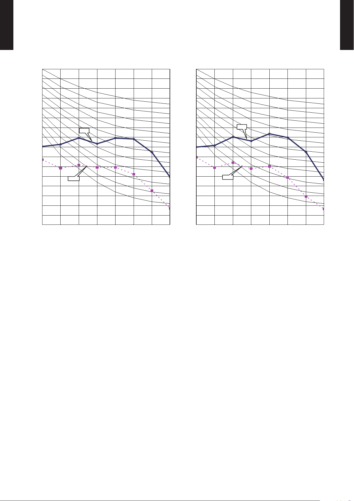
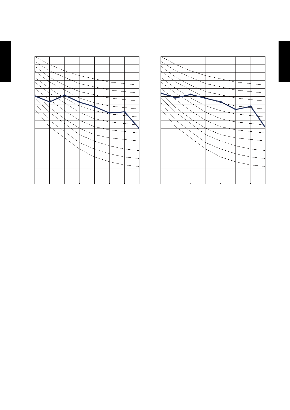
OPERATION NOISE8.
High
Quiet
High
Quiet
High
Quiet
High
Quiet
A24-30LC(F)
Ü
WALL MOUNTED TYPE
AS
NOISE LEVEL CURVE8-1.
MODEL : ASÜA24LC
Cooling
z
80
70
60
50
40
30
20
Octave band sound pressure level, dB:(0 dB= 0.0002µbar)
10
NC-65
NC-60
NC-55
NC-50
NC-45
NC-40
NC-35
NC-30
NC-25
NC-20
NC -15
Heating
z
80
70
60
50
40
30
20
Octave band sound pressure level, dB:(0 dB= 0.0002µbar)
10
NC-65
NC-60
NC-55
NC-50
NC-45
NC-40
NC-35
NC-30
NC-25
NC-20
NC -15
A24-30LC(F)
Ü
WALL MOUNTED TYPE
AS
0
63 125 250 500 1,00 0 2,00 0 4,000 8,0 00
Octave band center frequency,Hz
MODEL : ASÜA30LC
Cooling
z
80
70
60
50
40
30
20
Octave band sound pressure level, dB:(0 dB= 0.0002µbar)
10
NC-65
NC-60
NC-55
NC-50
NC-45
NC-40
NC-35
NC-30
NC-25
NC-20
NC -15
0
63 125 250 500 1,00 0 2,00 0 4,000 8,0 00
Octave band center frequency,Hz
Heating
z
80
70
60
50
40
30
20
Octave band sound pressure level, dB:(0 dB= 0.0002µbar)
10
NC-65
NC-60
NC-55
NC-50
NC-45
NC-40
NC-35
NC-30
NC-25
NC-20
NC -15
0
63 125 250 500 1,00 0 2,00 0 4,000 8,0 00
Octave band center frequency,Hz
- (01 - 16) -
0
63 125 250 500 1,00 0 2,00 0 4,000 8,0 00
Octave band center frequency,Hz
Page 20
A24-30LC(F)
High
Quiet
High
Quiet
Ü
WALL MOUNTED TYPE
AS
MODEL : ASÜA30LF
A24-30LC(F)
Ü
WALL MOUNTED TYPE
AS
Cooling
z
80
70
60
50
40
30
20
Octave band sound pressure level, dB:(0 dB= 0.0002µbar)
10
0
63 125 250 500 1,00 0 2,00 0 4,000 8,0 00
Octave band center frequency,Hz
NC-65
NC-60
NC-55
NC-50
NC-45
NC-40
NC-35
NC-30
NC-25
NC-20
NC -15
Heating
z
80
70
60
50
40
30
20
Octave band sound pressure level, dB:(0 dB= 0.0002µbar)
10
0
63 125 250 500 1,00 0 2,00 0 4,000 8,0 00
Octave band center frequency,Hz
NC-65
NC-60
NC-55
NC-50
NC-45
NC-40
NC-35
NC-30
NC-25
NC-20
NC -15
- (01 - 17) -
Page 21
A24-30LC(F)
Ü
WALL MOUNTED TYPE
AS
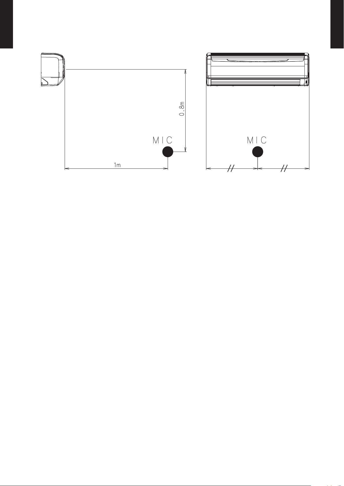
SOUND LEVEL CHECK POINT8-2.
A24-30LC(F)
Ü
WALL MOUNTED TYPE
AS
- (01 - 18) -
Page 22

ELECTRIC CHARACTERISTICS9.
A24-30LC(F)
Ü
WALL MOUNTED TYPE
AS
Model name ASÜA24LC ASÜA30LC, ASÜA30LF
Power supply
Max. operating current A 0.3 0.3
*1)Wiring Spec.
*1) Wiring Spec.
Selected Sample
(Selected based on Japan Electrotechnical Standard and Codes Committee E0005)
Volt ag e V 230~
Frequency Hz 50
Circuit breaker A 0.4 0.4
Connection cable mm
Limited wiring length m 31 51
2
1.5-2.5 1.5-2.5
A24-30LC(F)
Ü
WALL MOUNTED TYPE
AS
- (01 - 19) -
Page 23
SAFETY DEVICES10.
A24-30LC(F)
Ü
WALL MOUNTED TYPE
AS
Model
A24-30LC(F)
Ü
WALL MOUNTED TYPE
AS
Protection form
ASÜA24LC, ASÜA30LC, ASÜA30LF
Circuit protection Current fuse (PCB) 3.15A 250V
Terminal protection Current (thermal) fuse 3A 250V
+15
°C OFF
100
Fan motor protection Thermal protector program
95+5
-10
°C ON
-10
- (01 - 20) -
Page 24

OPTIONAL PARTS11.
SUMOTUWETH FR
SA
AM
PM
3 6 9
12 15 18 21
A24-30LC(F)
Ü
WALL MOUNTED TYPE
AS
Exterior Parts name Model No. Summary
Wired remote
controller
UTB-ÜUD
Unit control is performed by
wired remote controller.
A24-30LC(F)
Ü
WALL MOUNTED TYPE
AS
Fine dust, invisible mold
spores, and harmful
microorganisms are absorbed
Apple-catechin
lter
UTR- FA13 -1
onto the lter by static
electricity, and further growth
is inhibited and deactivated
by the polyphenol ingredient
extracted from apples.
The lter deodorizes by
Ion
deodorisation
lter
UTR- FA13 -2
powerfully decomposing
absorbed odors using the
oxidizing and reducing effects
of ions generated by the ultra
ne-particle ceramic.
External
connect kit
UTY-X WZ X
Use to connect with various
peripheral devices and air
conditioner PC board.
- (01 - 21) -
Page 25

A24-30LC(F)
SUMOTUWETH FR SA
7
3126 9
15 18 21
SUMOTUWETH FR SA
7
3126 9
15 18 21
Easy-to-understand time bar display
SUMOTUWETH FR SA
3126 9
15 18 21
Ü
WALL MOUNTED TYPE
AS
FEATURES
Various timer setup (ON / OFF / WEEKLY) are possible.
Ü
Equipped with weekly timer as standard function.
Ü
(2 times Start / Stop per day for a week)
When setting up a timer, operation mode and a temperature
Ü
setup can be changed.
When a failure occurs,the error code is displayed.
Ü
Error indication.
Ü
Easy installation with a slim shape with no bulge in the back.
Ü
Simple function setting
z
Setting of the air conditioner selection function is performed by remote controller.
High performance and compact size
z
Three functions are combined in one unit.
Wired
remote
controller
Weekly
+ +
timer
Setback
timer
A24-30LC(F)
Ü
WALL MOUNTED TYPE
AS
WIRED REMOTE CONTROLLER11-1.
Built-in timers
z
Weekly timer Setback timer
Possible to set ON/OFF time to operate twice each day
of the week.
Easy-to-understand time bar display
Setup screen example
(Set to Wednesday: 8:00 to 20:00.)
24°C
0 3 6 9 12 15 18 21 Time
At "Weekly timer" + "Set back timer" setup
24°C 28°C 24°C
Easy-to-understand operation
z
Screen
after setup
0 3 6 9 12 15 18 21 Time
Possible to set temperature for two time spans and
for each day of the week.
Setup screen example
(Set from Sunday to Saturday: 12:00 to 15:0 0, 28 °C.)
24°C
Simple installation
z
Components are compatible with standard
switch boxes. Flat back construction allows
equipment to be installed wherever it is
needed.
Timer
area
Operation
area
28°C
0 3 6 9 12 15 18 21 Time
28°C
[Variable timer control]
The operation/display sections are zoned
according to time and operation, enabling
variable programming to match application.
- (01 - 22) -
European
switch box
JIS box
Page 26

A24-30LC(F)
15
11
10
9
8
2
1
3
5
14
4
12
13
6
7
17
16
18
19
20
21
120
17
120
Ü
WALL MOUNTED TYPE
AS
FUNCTIONS
Display panel
DIMENSION
[ Unit : mm ]
1
START/STOP button
Pressed to start and stop operation.
2
Set temperature button
Selects the setting temperature.
3
Master control button
Selects the operating mode(AUTO, HEAT, FAN, COOL, DRY).
4
Fan control button
Selects the fan speed (AUTO, QUIET, LOW, MED, HIGH).
5
Economy button
Turns the economy efcient mode on and off.
6
Timer mode (CLOCK ADJUST) button
Selects the timer mode (OFF TIMER, ON TIMER, WEEKLY
TIMER). Set the current time.
7
Day (DAY OFF) button
Temporarily cancels of one day timer.
8
Set back button
Pressed to select the set back timer.
9
Set time button
Pressed to set time.
10
Delete button
The schedule of a weekly timer is deleted.
11
Set button
Sets the date, hour, minute and on-off time.
12
Vertical airow direction and swing button
Push for two seconds to change the swing mode.
13
Horizontal airow direction and swing button
Push for two seconds to change the swing mode.
14
Filter button
15
Operation lamp
Lights during operation and when the timer is on.
16
Timer and clock display
17
Operation mode display
18
Fan speed display
19
Operation lock display
20
Temperature display
21
Function display
Defrost display
Thermo sensor display
Economy display
Vertical swing display
Horizontal swing display
Filter display
A24-30LC(F)
Ü
WALL MOUNTED TYPE
AS
Functions will be di fferent due to ty pe of indo or unit.
For details, please see oper ation manual.
SPECIFICATION
SIZE (H x W x D mm) 120 x 120 x 17
WEIGHT ( g ) 160
CABLE LENGTH ( m ) 10
POWER ( V ) 12
- (01 - 23) -
Page 27

A24-30LC(F)
ON
OFF
ON ONOFF OFF
OPERATION
STOP
Orange
External
input
External
output
1
3
Yellow
Indoor unit External device
( Field supply )
Print circuit
board
Orange
External
input
External
output
1
3
Yellow
Indoor unit External device
( Field supply )
Print circuit
board
Ü
WALL MOUNTED TYPE
AS
EXTERNAL CONNECT KIT11-2.
This kit allows to operate the air conditioner, such as stopping and starting, using an external
A24-30LC(F)
Ü
WALL MOUNTED TYPE
AS
device, and output the operation status of the air conditioner.
Only operation and stop signals will be output. •
Use the remote control to check the operation mode, temperature, and airow.
Check the error information on the display area of the main unit.
Operation mode, temperature, and airow cannot be set by external input. Use the remote •
controller to set.
If the air-conditioner is activated by external input, it will operate in the settings before stop. •
To change the settings, use the remote controller.
CONTROL INPUT SETTING
You can control air conditioner ON / OFF operation by external input. •
Signal specication
z
No voltage ON/OFF continuous signal. •
Contact capacity : DC12V 10mA •
External input signal
Remote controller signal
Indoor unit status
Installation example
z
For remote operation •
For external timer operation •
- (01 - 24) -
Page 28

A24-30LC(F)
SHORT
OPEN
OPERATION
STOP
Blue
External
input
Vc
Ic
External
output
1
2
Purple
Indoor unit
External device
( Field supply )
Print circuit
board
Ü
WALL MOUNTED TYPE
AS
OPERATING OUTPUT SETTING
A24-30LC(F)
Ü
WALL MOUNTED TYPE
AS
You can display air conditioner ON / OFF operation by e xternal o utput. •
Signal specication
z
No voltage contact. •
Contact capacity : Max. DC24V 10mA to 1A or less •
Indoor unit status
External output signal
Installation example
z
For operation display •
- (01 - 25) -
Page 29

2. OUTDOOR UNIT
SINGLE TYPE :
AOÜR24LCC
AOÜR30LCT
AOÜR30LFT
D1D_AO001E/03
2009.11.19
Page 30

2. OUTDOOR UNIT
CONTENTS
R24-30LC(F)
Ü
OUTDOOR UNIT
AO
1. SPECIFICATIONS
2. DIMENSIONS
3. REFRIGERANT CIRCUIT
4. WIRING DIAGRAMS
.............................................................................................. 02 - 01
........................................................................................................ 02 - 03
............................................................................ 02 - 05
........................................................................................ 02 - 07
R24-30LC(F)
Ü
OUTDOOR UNIT
AO
5. CAPACITY COMPENSATION RATE FOR PIPE LENGTH AND
HEIGHT DIFFERENCE
6. ADDITIONAL CHARGE CALCULATION
7. AIR FLOW
................................................................................................................ 02 - 13
8. OPERATION NOISE
8-1. NOISE LEVEL CURVE
8-2. SOUND LEVEL CHECK POINT
.................................................................................. 02 - 10
......................................... 02 - 12
......................................................................................... 02 - 15
.................................................................................... 02 - 15
..................................................................... 02 - 17
9. ELECTRIC CHARACTERISTICS
10. SAFETY DEVICES
............................................................................................ 02 - 19
........................................................... 02 - 18
Page 31

SPECIFICATIONS1.
Type INVERTER HEAT PUMP
Model name AOÜR24LCC AOÜR30LCT
Power source 230V~ 50Hz
Available voltage range 198-264V ~ 50Hz
Starting current A 9.8 11. 7
Airow
Fan
R24-30LC(F)
Ü
OUTDOOR UNIT
AO
Sound pressure level
Heat exchanger type
Compressor
Refrigerant
Refrigerant oil Type PVE (FV50S)
Enclosure
Dimensions
( H×W×D)
Weight
Connection pipe
Operation range
rate
Type × Q'ty Propeller fan×1
Motor output W 65 100
Type × Q'ty Scroll × 1 Rotary × 1
Motor output W 1,20 0 1,70 0
Net
Gross 648 × 910 × 380 970 × 1050 × 445
Net
Gross 48 (105.8) 70 (154)
Size
Method Flare Flare
Max. length
Max. height difference 20 30
Cooling
Heating 2,470 3,800
Cooling
Heating 53 55
Dimensions (H × W × D)
Fin pitch Main:1.4, Sub:1.4 1.3
Rows x Stages Main:2 × 26, Sub:1 × 24 2 × 38
Pipe type Copper
Fin Type Aluminum
Type R 410 A
Charge g 1,60 0 2 ,100
Material Steel
Colour
Liquid
Gas Ø15.88 (Ø 5/8 in.) Ø15.88 (Ø 5/8 in.)
Cooling
Heating -15 to 24
3
m
/h
dB(A)
mm
mm
kg(l b.)
mm
m
°C
Main : 546 × 866 × 36.4
Sub : 504 × 589 × 18.2
2,340 3,600
52 53
798 × 900 × 36.4
BEIGE
Approximate colour of MUNSELL 10YR7.5/1.0
578 × 790 × 315 830 × 900 × 330
44 (97) 62 (137)
Ø6.35 (Ø 1/4 in.) Ø9.52 (Ø 3/8 in.)
30 (chargeless : 15) 50 (chargeless : 20)
-10 to 43
R24-30LC(F)
Ü
OUTDOOR UNIT
AO
Note :
Specications are based on the following conditions.
Cooling : Indoor temperature of 27°CD B/19°CWB. and outdoor temperature of 35°CDB/24°CWB.
Heating : Indoor temperature of 20°CDB/15°CWB. and outdoor temperature of 7°CDB/6°CWB.
Pipe length : 7.5 m, Height dif ferenc e : 0 m. (Outdoor unit - Indoor unit)
- (02 - 01) -
Page 32

Type INVERTER HEAT PUMP
Model name AOÜR30LFT
Power source 230V~ 50Hz
Available voltage range 198-264V ~ 50Hz
Starting current A 10.9
Airow
Fan
R24-30LC(F)
Ü
OUTDOOR UNIT
AO
Sound pressure level
rate
Type × Q'ty Propeller fan×1
Motor output W 100
Heat exchanger type
Cooling
Heating 3,600
Cooling
Heating 55
Dimensions (H × W × D)
Fin pitch 1.3
3
m
/h
dB(A)
mm
Rows x Stages 2×38
3,600
53
798×900×36.4
R24-30LC(F)
Ü
OUTDOOR UNIT
AO
Pipe type Copper
Type(Material) Corrugate (Aluminum)
Surface treatment Corrosion resistance
Compressor
Refrigerant
Fin
Type × Q'ty Rotary ×1
Motor output W 2,10 0
Type R410A
Charge g 2,10 0
Refrigerant oil Type POE (RB68)
Material Steel
Enclosure
Dimensions
( H×W×D)
Weight
Connection pipe
Operation range
Colour
Net
Gross 970×1050×445
Net
Gross 68 (150)
Size
Liquid
Gas Ø15.88 (Ø 5/8 in.)
mm
kg(l b.)
mm
Approximate colour of MUNSELL 10YR7.5/1.0
Method Flare
Max. length
Max. height difference 30
Cooling
Heating -15 to 24
m
°C
BEIGE
830×900×330
61 (135)
Ø9.52 (Ø 3/8 in.)
50(chargeless:20)
-10 to 46
Note :
Specications are based on the following conditions.
Cooling : Indoor temperature of 27 °CDB / 19 °CWB.and outdoor temperature of 35 °CDB/24 °CWB.
Heating : Indoor temperature of 20 °CDB / 15 °CWB.and outdoor temperature of 7 °CDB/6 °CWB.
Pipe length : 7.5 m, Height dif ferenc e : 0 m.(Outdoor unit - Indoor unit)
- (02 - 02) -
Page 33
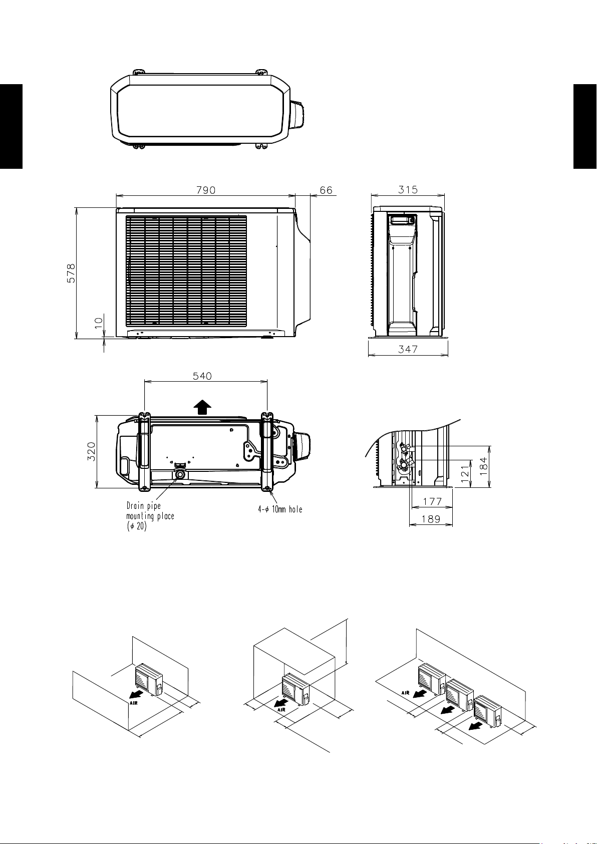
DIMENSIONS2.
600 mm
or more
100 mm
or more
600 mm or more
300 mm
or more
100 mm
or more
250 mm or more
(Service space)
250 mm
or more
250 mm
or more
300 mm
or more
Air flow
Top view
Front view
Side view
Bottom view
MODEL : AOÜR24LC
(Unit : mm)
R24-30LC(F)
Ü
OUTDOOR UNIT
AO
R24-30LC(F)
Ü
OUTDOOR UNIT
AO
INSTALLATION PLACE
When there are obstacles at
the back or front sides.
When there are obstacles at
the back, side(s), and top.
When there are obstacles at the
back, side with the installation of
more than one unit.
- (02 - 03) -
Page 34

MODEL : AOÜR30LC, AOÜR30LF
600 mm
or more
100 mm
or more
600 mm or more
300 mm
or more
100 mm
or more
250 mm or more
(Service space)
250 mm
or more
250 mm
or more
300 mm
or more
Air flow
900
650
830
370
99
196
21
9
77
31 330
400
170
147
12
Top view
Front view
Side view
Bottom view
(Unit : mm)
R24-30LC(F)
Ü
OUTDOOR UNIT
AO
R24-30LC(F)
Ü
OUTDOOR UNIT
AO
INSTALLATION PLACE
When there are obstacles at
the back or front sides.
When there are obstacles at
the back, side(s), and top.
- (02 - 04) -
When there are obstacles at the
back, side with the installation of
more than one unit.
Page 35

REFRIGERANT CIRCUIT3.
2-Way
valve
Strainer
Strainer
Strainer
3-Way
valve
Muffler
4-Way valve
Expansion valve
Heat exchanger
( INDOOR )
Heat exchanger
( OUTDOOR )
Sub-accumulator
Compressor
Cooling
Heating
MODEL : AOÜR24LC
R24-30LC(F)
Ü
OUTDOOR UNIT
AO
R24-30LC(F)
Ü
OUTDOOR UNIT
AO
Refrigerant pipe diameter
Liquid : 1/4" (6.35 mm)
Gas : 5/8" (15.88 mm)
- (02 - 05) -
Page 36

MODEL : AOÜR30LC,AOÜR30LF
3-Way
valve
(Small)
3-Way
valve
(Large)
Strainer
Strainer
Muffler
Pressure
switch
4-Way valve
Expansion valve
Heat exchanger
( INDOOR )
Heat exchanger
( OUTDOOR )
Sub-accumulator
Compressor
Cooling
Heating
R24-30LC(F)
Ü
OUTDOOR UNIT
AO
R24-30LC(F)
Ü
OUTDOOR UNIT
AO
Refrigerant pipe diameter
Liquid : 3/8" (9.52 mm)
Gas : 5/8" (15.88 mm)
- (02 - 06) -
Page 37
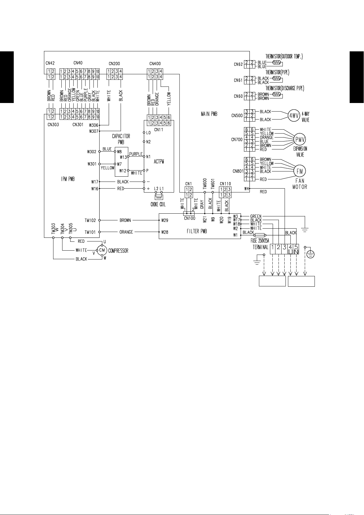
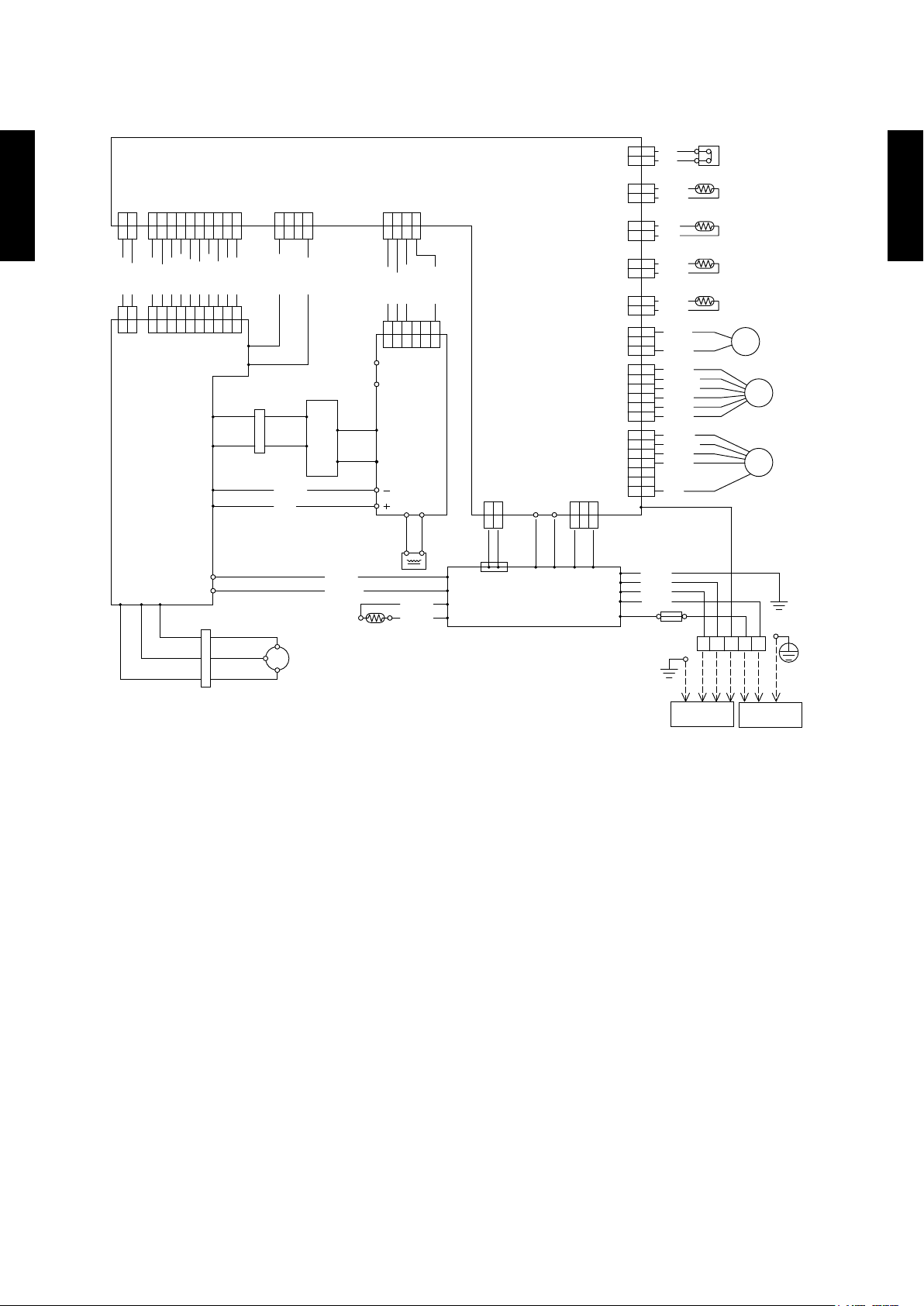
WIRING DIAGRAMS4.
TO INDOOR
UNIT
TO POWER
SUPPLY
MODEL : AOÜR24LC
R24-30LC(F)
Ü
OUTDOOR UNIT
AO
R24-30LC(F)
Ü
OUTDOOR UNIT
AO
- (02 - 07) -
Page 38
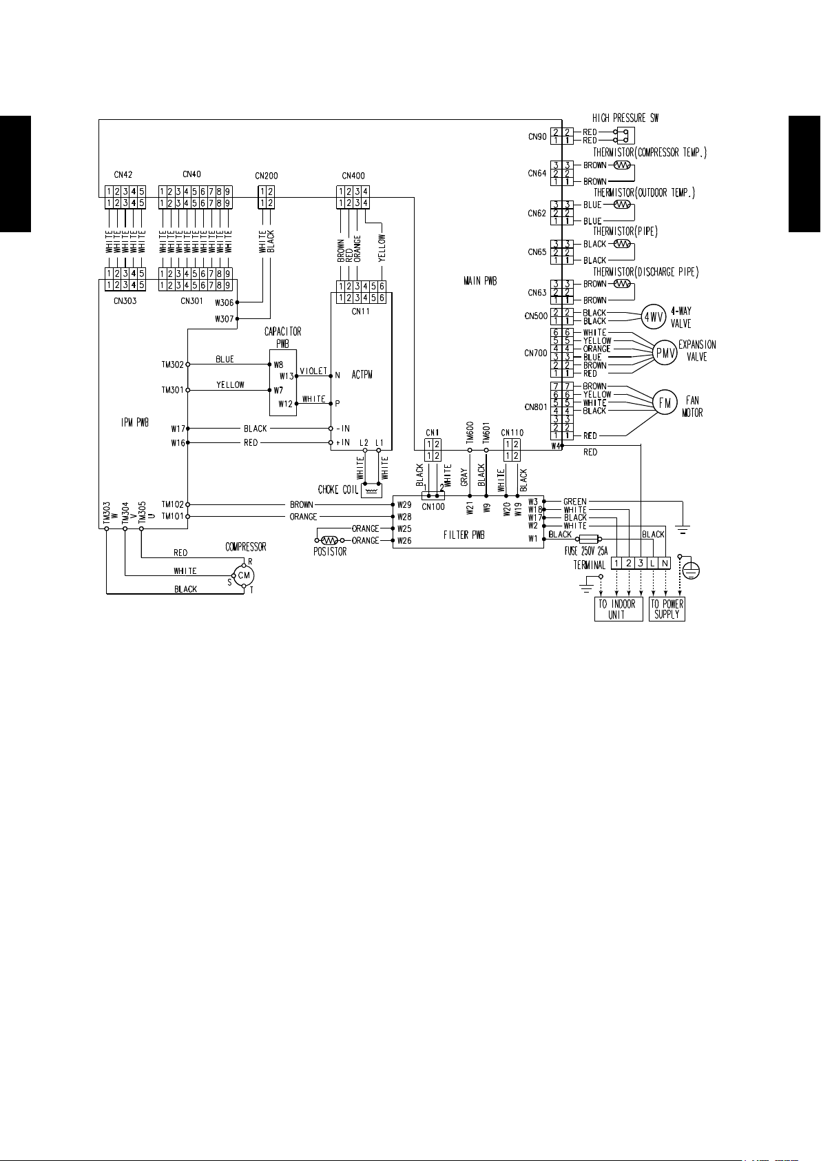
MODEL : AOÜR30LC
YELLOW
YELLOW
GREEN
BLUE
BLUE BLUE
YELLOW YELLOW
BLACK
BLACK BLACK
PURPLE
WHITE
WHITEWHITE
RED
RED RED
R
CM
C
S
BROWN
ORANGE
ORANGE
WHITE
WHITE
BLACK
BLACK BLACK
GREEN
RED
RED
RED
BROWN
BROWN
BROWN
BROWN
BROWN
BROWN
RED
RED
BLUE
BLUE
BLUE
ORANGE
YELLOW
YELLOW
WHITE
WHITE
BLACK
BLACK
BLACK
BLACK
BLACK
ORANGE
PURPLE
GRAY
GRAY
BLACK
BLACK
BLACK
BLACK
WHITE
WHITE
WHITE
WHITE
WHITE
WHITE
WHITE
BROWN
RED
BROWN
BROWN
RED
RED
ORANGE
ORANGE
CONNECTOR
MAIN PWB
ACTPM
CONNECTOR
POSISTOR
FILTER PWB
FUSE 250V 25A
TERMINAL
FAN
MOTOR
FM
PMV
4WV
EXPANSION
VALVE
HIGH PRESSURE SW
THERMISTOR(COMPRESSOR TEMP.)
THERMIST
OR(OUTDOOR TEMP.)
THERMISTOR(PIPE)
THERMISTOR(DISCHARGE PIPE)
4-WAY
VALVE
CHOKE COIL
COMPRESSOR
IPM PWB
CAPACITOR
PWB
CN303 CN301
CN42 CN40 CN200 CN400
CN11
L0
N2
W8
W7
W1 3
W1 2
N1
L2
W2 9
CN110
TM 60 0
TM 60 1
CN801
W4
CN700
CN500
CN60
CN61
CN61
CN64
CN90
CN1
W1
W2
W1 8
W1 7
W3
W2 1
W9
W2 0
W1 9
CN100
W2 8
W2 5
W2 6
L1
P
W306
W302
W301
W1 7
W1 6
TM102
W3 03
W
V
U
W3 04
W3 05
TM101
W307
54768
10
9321 21
54768
10
9321 21
5
4 6321
5
4 6321
321
3 L N21
33221
1
6
7
5
4
3
2
1
6
7
5
4
3
2
1
6
5
4
3
2
1
3
2
1
3
2
1
212
1
212
1
212
1
212
1
212
1
6
5
4
221
1
21
54768
10
9321 21
54768
10
9321 21
4321
4321
4321
4321
TO INDOOR
UNIT
TO POWER
SUPPLY
R24-30LC(F)
Ü
OUTDOOR UNIT
AO
R24-30LC(F)
Ü
OUTDOOR UNIT
AO
- (02 - 08) -
Page 39
MODEL : AOÜR30LF
R24-30LC(F)
Ü
OUTDOOR UNIT
AO
R24-30LC(F)
Ü
OUTDOOR UNIT
AO
- (02 - 09) -
Page 40
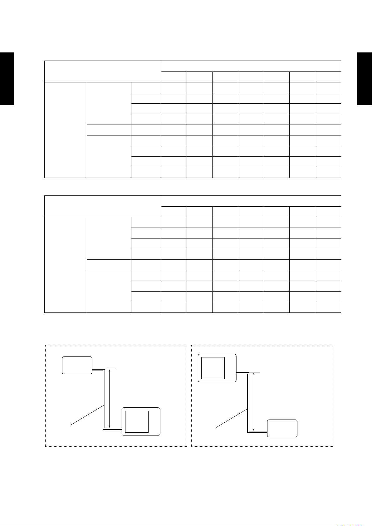
CAPACITY COMPENSATION RATE FOR PIPE LENGTH 5.
AND HEIGHT DIFFERENCE
MODEL : AOÜR24LC
COOLING
R24-30LC(F)
Ü
OUTDOOR UNIT
AO
Height
difference H
(m)
HEATING
Height
difference H
(m)
1
Û
Indoor unit is
upper than
outdoor unit.
2
Û
Indoor unit is
under than
outdoor unit
1
Û
Indoor unit is
upper than
outdoor unit.
2
Û
Indoor unit is
under than
outdoor unit
20 - - - 0. 9 51 0.952 0. 9 51 0 .951
10 - - 0.980 0.966 0.968 0.967 0.966
7. 5 - 0.988 0.984 0.970 0.972 0.971 0.970
5 0.995 0.992 0.988 0.974 0.976 0.975 0.9 74
0 1.003 1.000 0.996 0.982 0.983 0.983 0.982
-5 1.003 1.000 0.996 0.982 0.983 0.983 0.982
-7.5 - 1.000 0.996 0.982 0.983 0.983 0.982
-10 - - 0.996 0.982 0.983 0.983 0.982
-20 - - - 0.982 0.983 0.983 0.982
20 - - - 0.975 0.954 0.932 0.908
10 - - 0.998 0.975 0.954 0.932 0.908
7. 5 - 1.000 0.998 0.975 0.954 0.932 0.908
5 0.989 1.000 0.998 0.975 0.954 0.932 0.908
0 0.989 1.000 0.998 0.975 0.954 0.932 0.908
-5 0.984 0.995 0.993 0.970 0.950 0.927 0.903
-7.5 - 0.993 0.991 0.968 0.947 0.925 0.901
-10 - - 0.988 0.965 0.945 0.923 0.899
-20 - - - 0.956 0.935 0.914 0.890
5 7. 5 10 15 20 25 30
5 7. 5 10 15 20 25 30
Pipe length (m)
Pipe length (m)
R24-30LC(F)
Ü
OUTDOOR UNIT
AO
Height difference H
Indoor unit
Outdoor unit
Connection pipe
1 Indoor unit is upper than outdoor unit.
Outdoor unit
Indoor unit
Connection pipe
2 Indoor unit is under than outdoor unit.
- (02 - 10) -
Page 41

MODEL : AOÜR30LC, AOÜR30LF
COOLING
R24-30LC(F)
Ü
OUTDOOR UNIT
AO
Height
difference H
(m)
HEATING
Height
difference H
(m)
1
Û
Indoor unit is
upper than
outdoor unit.
2
Û
Indoor unit is
under than
outdoor unit
1
Û
Indoor unit is
upper than
outdoor unit.
2
Û
Indoor unit is
under than
outdoor unit
20 - - - 0.945 0.947 0.945 0.940
10 - - 0.984 0.961 0.963 0.960 0.956
7. 5 - 0.988 0.988 0.965 0.967 0.964 0.959
5 0.990 0.992 0.992 0.968 0.971 0.968 0.963
0 0.998 1.000 1.000 0.976 0.979 0.976 0.971
-5 0.998 1.000 1.000 0.976 0.979 0.976 0.971
-7.5 - 1.000 1.000 0.976 0.979 0.976 0. 971
-10 - - 1.000 0.976 0.979 0.976 0.971
-20 - - - 0.976 0.979 0.976 0.971
20 - - - 0.872 0.816 0.756 0.686
10 - - 0.991 0.872 0.816 0.756 0.686
7. 5 - 1.000 0.991 0.872 0.816 0.756 0.686
5 0.986 1.000 0.991 0.872 0.816 0.756 0.686
0 0.986 1.000 0.991 0.872 0.816 0.756 0.686
-5 0.981 0.995 0.986 0.868 0.812 0.752 0.683
-7.5 - 0.993 0.983 0.866 0.810 0.750 0.681
-10 - - 0.981 0.864 0.808 0.74 8 0.679
-20 - - - 0.855 0.799 0.740 0.672
5 7. 5 10 20 30 40 50
5 7. 5 10 20 30 40 50
Pipe length (m)
Pipe length (m)
R24-30LC(F)
Ü
OUTDOOR UNIT
AO
Height difference H
Indoor unit
Outdoor unit
Connection pipe
1 Indoor unit is upper than outdoor unit.
Outdoor unit
Indoor unit
Connection pipe
2 Indoor unit is under than outdoor unit.
- (02 - 11) -
Page 42

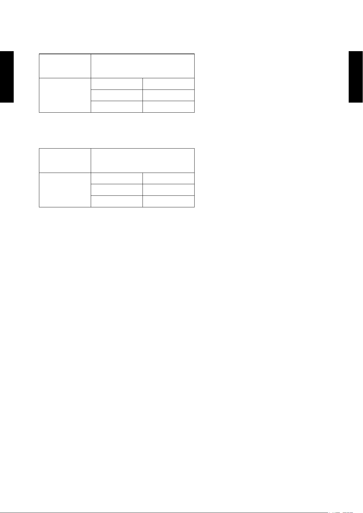
ADDITIONAL CHARGE CALCULATION6.
MODEL : AOÜR24LC
Refrigerant type R410A
Refrigerant amount g 1600
REFRIGERANT CHARGE
R24-30LC(F)
Ü
OUTDOOR UNIT
AO
z
Pipe length m ~15 20 25 30
Additional charge g 0 (Chargeless) +100 +200 +300
MODEL : AOÜR30LC, AOÜR30LF
Refrigerant type R410A
Refrigerant type R410A
Refrigerant amount g 2100
Refrigerant amount g 2100
REFRIGERANT CHARGE
z
20g/m
R24-30LC(F)
Ü
OUTDOOR UNIT
AO
Pipe length m ~20 30 40 50
Additional charge g 0 (Chargeless) +400 +800 +120 0
40g/m
- (02 - 12) -
Page 43

AIR FLOW7.
MODEL : AOÜR24LC
COOLING
z
Number of
rotations
(r.p.m.)
R24-30LC(F)
Ü
OUTDOOR UNIT
AO
1000
HEATING
z
Number of
rotations
(r.p.m.)
2340 m
650 l/s
1377 CFM
2470 m
Air ow
Air ow
3
/h
3
/h
R24-30LC(F)
Ü
OUTDOOR UNIT
AO
1050
686 l/s
145 4 CFM
MODEL : AOÜR30LC
COOLING
z
Number of
rotations
(r.p.m.)
3600 m
850
HEATING
z
Number of
rotations
(r.p.m.)
1000 l/s
2119 CFM
3800 m
Air ow
Air ow
3
/h
3
/h
900
1056 l/s
2236 CFM
- (02 - 13) -
Page 44
MODEL : AOÜR30LF
COOLING
z
Number of
rotations
(r.p.m.)
R24-30LC(F)
Ü
OUTDOOR UNIT
AO
850
3600 m
1000 l/s
2119 CFM
HEATING
z
Number of
rotations
(r.p.m.)
3600 m
Air ow
Air ow
3
/h
3
/h
R24-30LC(F)
Ü
OUTDOOR UNIT
AO
850
1000 l/s
2119 CFM
- (02 - 14) -
Page 45

OPERATION NOISE8.
NOISE LEVEL CURVE8-1.
MODEL : AOÜR24LC
Cooling
z
80
R24-30LC(F)
Ü
OUTDOOR UNIT
AO
70
60
50
40
30
20
Octave band sound pressure level, dB:(0 dB= 0.0002µbar)
10
0
63 125 250 500 1,00 0 2,00 0 4,000 8,0 00
Octave band center frequency,Hz
NC-65
NC-60
NC-55
NC-50
NC-45
NC-40
NC-35
NC-30
NC-25
NC-20
NC -15
Heating
z
80
70
60
50
40
30
20
Octave band sound pressure level, dB:(0 dB= 0.0002µbar)
10
0
63 125 250 500 1,00 0 2,00 0 4,000 8,0 00
Octave band center frequency,Hz
NC-65
NC-60
NC-55
NC-50
NC-45
NC-40
NC-35
NC-30
NC-25
NC-20
NC -15
R24-30LC(F)
Ü
OUTDOOR UNIT
AO
MODEL : AOÜR30LC
Cooling
z
80
70
60
50
40
30
20
Octave band sound pressure level, dB:(0 dB= 0.0002µbar)
10
NC-65
NC-60
NC-55
NC-50
NC-45
NC-40
NC-35
NC-30
NC-25
NC-20
NC -15
Heating
z
80
70
60
50
40
30
20
Octave band sound pressure level, dB:(0 dB= 0.0002µbar)
10
NC-65
NC-60
NC-55
NC-50
NC-45
NC-40
NC-35
NC-30
NC-25
NC-20
NC -15
0
63 125 250 500 1,00 0 2,00 0 4,000 8,0 00
Octave band center frequency,Hz
- (02 - 15) -
0
63 125 250 500 1,00 0 2,00 0 4,000 8,0 00
Octave band center frequency,Hz
Page 46
MODEL : AOÜR30LF
Cooling
z
80
R24-30LC(F)
Ü
OUTDOOR UNIT
AO
70
60
50
40
30
20
Octave band sound pressure level, dB:(0 dB= 0.0002µbar)
10
0
63 125 250 500 1,00 0 2,00 0 4,000 8,0 00
Octave band center frequency,Hz
NC-65
NC-60
NC-55
NC-50
NC-45
NC-40
NC-35
NC-30
NC-25
NC-20
NC -15
Heating
z
80
70
60
50
40
30
20
Octave band sound pressure level, dB:(0 dB= 0.0002µbar)
10
0
63 125 250 500 1,00 0 2,00 0 4,000 8,0 00
Octave band center frequency,Hz
NC-65
NC-60
NC-55
NC-50
NC-45
NC-40
NC-35
NC-30
NC-25
NC-20
NC -15
R24-30LC(F)
Ü
OUTDOOR UNIT
AO
- (02 - 16) -
Page 47

SOUND LEVEL CHECK POINT8-2.
R24-30LC(F)
Ü
OUTDOOR UNIT
AO
R24-30LC(F)
Ü
OUTDOOR UNIT
AO
- (02 - 17) -
Page 48

ELECTRIC CHARACTERISTICS9.
Model name AOÜR24LC AOÜR30LC AOÜR30LF
Power supply
*1) Max operating current A 17. 5 19.0 19.0
Starting Current A 9.8 11.7 10.9
R24-30LC(F)
Ü
OUTDOOR UNIT
AO
*2) Wiring Spec.:
*1) The maximum current is the total current of indoor unit and outdoor unit.
*2) Wiring Spec.:
Selected Sample
(Selected based on Japan Electrotechnical Standard and Codes Committee E0005)
*3) Limited wiring length :
This is the wiring length in case voltage descent is less than 2%.
When the wiring length becomes long, please select the wiring of a more larger diameter.
Voltage V 230~
Frequency Hz 50
Main Fuse (Circuit breaker)
Current
Power Cable mm
A 30 30
2
3.5-4.5 3.5-4.5
*3) Limited wiring length : m 20 19
R24-30LC(F)
Ü
OUTDOOR UNIT
AO
- (02 - 18) -
Page 49

SAFETY DEVICES10.
Model
Protection form
AOÜR24LC AOÜR30LC, AOÜR30LF
Current fuse
R24-30LC(F)
Ü
OUTDOOR UNIT
AO
Circuit protection
(NEAR THE TERMINAL)
Current fuse
20A 250V 20A 250V
5A 250V 5A 250V
15A 250V 15A 250V
R24-30LC(F)
Ü
OUTDOOR UNIT
AO
(MAIN PRINTED
Fan motor
protection
High Pressure
Protection
Compressor
protection
CIRCUIT BOARD)
Thermal protection
program
Pressure Switch
Thermal protection program
(DISCHARGE TEMP.)
Thermal protection program
(DISCHARGE TEMP.)
3.15A 250V 3.15A 250V
-
-
+15
+15
°C
-10
°C
-10
OFF : 130±20°C
ON : 100±20°C
OFF : 4.2±0.1MPa
ON : 3.2±0.15MPa
OFF : 110°C
ON : After 40 minutes
OFF:110°C
ON: After 7 minutes
OFF :100
ON : 105
OFF : 110°C
ON : After 7 minutes
- (02 - 19) -
 Loading...