

Page 1
TECHNICAL MANUAL
WALL MOUNTED TYPE AND
FLOOR / CEILING UNIVERSAL TYPE
AIR CONDITIONER
Page 2

– 1 –
CONTENTS
1. FEATURES . . . . . . . . . . . . . . . . . . . . . . . . . . . . . . . . . . . . . . . . . . . . . . . 2
1.1 MODEL IDENTIFICATION . . . . . . . . . . . . . . . . . . . . . . . . . . . . . . . . . . . . . . . . . . . . 2
1.2 APPLICATION MODEL . . . . . . . . . . . . . . . . . . . . . . . . . . . . . . . . . . . . . . . . . . . . . . 3
1.3 FEATURES OF EACH MODEL . . . . . . . . . . . . . . . . . . . . . . . . . . . . . . . . . . . . . . . 6
1.4 PRINTED WIRING BOARD SETTINGS . . . . . . . . . . . . . . . . . . . . . . . . . . . . . . . . 18
2. SPECIFICATIONS . . . . . . . . . . . . . . . . . . . . . . . . . . . . . . . . . . . . . . . . 20
2.1 COMPACT SII, MII & LI SERIES
(AS ✽ 7A, 7R, 9A, 9R, 12A, 12R, 14A, 14R, 17A, 17R) . . . . . . . . . . . . . . . . . . . . 20
2.2 WALL MOUNTED LARGE AS-SERIES
(AS ✽ 20A, 20R, 24A, 24R, 30A, 30R) . . . . . . . . . . . . . . . . . . . . . . . . . . . . . . . . . . 23
2.3 UNIVERSAL AB-SERIES
(AB ✽ 14A, 14R, 18A, 18R, 24A, 24R) . . . . . . . . . . . . . . . . . . . . . . . . . . . . . . . . . . 27
3. OUTLINE AND DIMENSIONS . . . . . . . . . . . . . . . . . . . . . . . . . . . . . . 30
3.1 MODELS : AS ✽ 7A, 7R . . . . . . . . . . . . . . . . . . . . . . . . . . . . . . . . . . . . . . . . . . . . . 30
3.2 MODELS : AS ✽ 9A, 9R, 12A, 12R . . . . . . . . . . . . . . . . . . . . . . . . . . . . . . . . . . . . 31
3.3 MODELS : AS ✽ 14A, 14R . . . . . . . . . . . . . . . . . . . . . . . . . . . . . . . . . . . . . . . . . . . 32
3.4 MODELS : AS ✽ 17A, 17R . . . . . . . . . . . . . . . . . . . . . . . . . . . . . . . . . . . . . . . . . . . 33
3.5 MODELS : AS ✽ 20A, 20R, 24A, 24R, 30A, 30R, ASC-502B, ASC-602B . . . . . . 34
3.6 MODELS : AS ✽ 14A, 14R, 18A, 18R, 24A, 24R . . . . . . . . . . . . . . . . . . . . . . . . .36
4. DATA . . . . . . . . . . . . . . . . . . . . . . . . . . . . . . . . . . . . . . . . . . . . . . . . . . . 38
4.1 PERFORMANCE CURVE . . . . . . . . . . . . . . . . . . . . . . . . . . . . . . . . . . . . . . . . . . . 38
4.2 TEMPTERATURE RANGE . . . . . . . . . . . . . . . . . . . . . . . . . . . . . . . . . . . . . . . . . . 48
4.3 REFRIGERANT CHARGING . . . . . . . . . . . . . . . . . . . . . . . . . . . . . . . . . . . . . . . . 49
4.4 AIR VELOCITY DISTRIBUTION . . . . . . . . . . . . . . . . . . . . . . . . . . . . . . . . . . . . . 52
4.5 NOISE LEVEL MEASUREMENT . . . . . . . . . . . . . . . . . . . . . . . . . . . . . . . . . . . . . 64
5. DIAGRAMS . . . . . . . . . . . . . . . . . . . . . . . . . . . . . . . . . . . . . . . . . . . . . . 69
5.1 REFRIGERANT SYSTEM DIAGRAM . . . . . . . . . . . . . . . . . . . . . . . . . . . . . . . . . 69
5.2 CIRCUT DIAGRAM . . . . . . . . . . . . . . . . . . . . . . . . . . . . . . . . . . . . . . . . . . . . . . . . 84
5.3 CONTROLLER CIRCUIT DIAGRAM EZ NUMBER LIST . . . . . . . . . . . . . . . 104
5.4 CONTROLLER PCB CIRCUIT DIAGRAM . . . . . . . . . . . . . . . . . . . . . . . . . . . . 108
5.5 REMOTE CONTR OLLER CIRCUIT DIA GRAM . . . . . . . . . . . . . . . . . . . . . . . . 119
6. INSTALLATION INSTRUCTIONS . . . . . . . . . . . . . . . . . . . . . . . . . . . . 129
6.1 SPLIT TYPE ROOM AIR CONDITIONER (AS ✽ 20A, 24A) . . . . . . . . . . . . . 129
6.2 FLOOR CONSOLE / UNDERCEILING DUAL TYPE
(AB ✽ 18A, 18R, 24A, 24R) . . . . . . . . . . . . . . . . . . . . . . . . . . . . . . . . . . . . . . . . . 144
Page 3
1. FEATURES
– 2 –
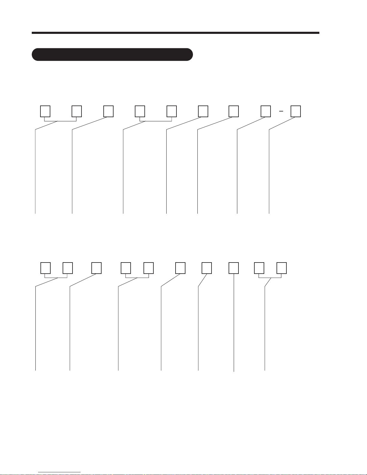
1.1 MODEL IDENTIFICATION
Example
INDOOR UNIT
OUTDOOR UNIT
A
1
TYPE
AS: WALL
MOUNTED
AB: UNIVERSAL
(FLOOR/CEILING)
DESTINATION
MARKET REGIONS
G: 220-240V 50Hz
S: 220V 60Hz
B: 220V 60Hz
T: 240 - (220)V 50Hz
Y: 220-240V 50Hz
H: 220-240V 50Hz
Q: 220V 50Hz
COOLING/
HEATING RANK
BTU/h(kW)
7: 7,000 (2.1)
9: 9,000 (2.7)
12: 12,000 (3.6)
14: 14,000 (4.0)
18: 18,000 (5.2)
20: 20,000 (5.9)
24: 24,000 (7.0)
30: 30,000 (8.8)
FUNCTION
TYPE
A: COOLING
ONLY
R: REVERSE
CYCLE
(HEAT &
COOL)
CONTROL
METHOD
(
REMOTE CONTROL
)
S: WIRELESS type
(Handy type)
W: WIRELESS type
(Wall fixing type)
SHOWING
MINOR
CHANGES
COLOR
W: WHITE
S
2
∗
3
2
4
4
5
R
6
S
7
G
8
W
109
A
1
TYPE
AO: OUTDOOR
DESTINATION
MARKET REGIONS
G: 220-240V 50Hz
S: 220V 60Hz
B: 220V 60Hz
T: 240 - (220)V 50Hz
Y: 220-240V 50Hz
H: 220-240V 50Hz
Q: 220V 50Hz
COOLING/
HEATING RANK
BTU/h(kW)
7: 7,000 (2.1)
9: 9,000 (2.7)
12: 12,000 (3.6)
14: 14,000 (4.0)
18: 18,000 (5.2)
20: 20,000 (5.9)
24: 24,000 (7.0)
30: 30,000 (8.8)
FUNCTION
TYPE
A: COOLING
ONLY
R: REVERSE
CYCLE
(HEAT &
COOL)
SHOWING
COMPRESSOR
USED
SHOWING
MINOR
CHANGES
SPECIAL
METHOD
FUNCTION
L: LOW AMBIENT
TEMP.
OPERATION
O
2 10
∗
3
2
4
4
5
R
6
W
78L9
G
This list applies to new models
since June 1997.
Page 4
– 3 –
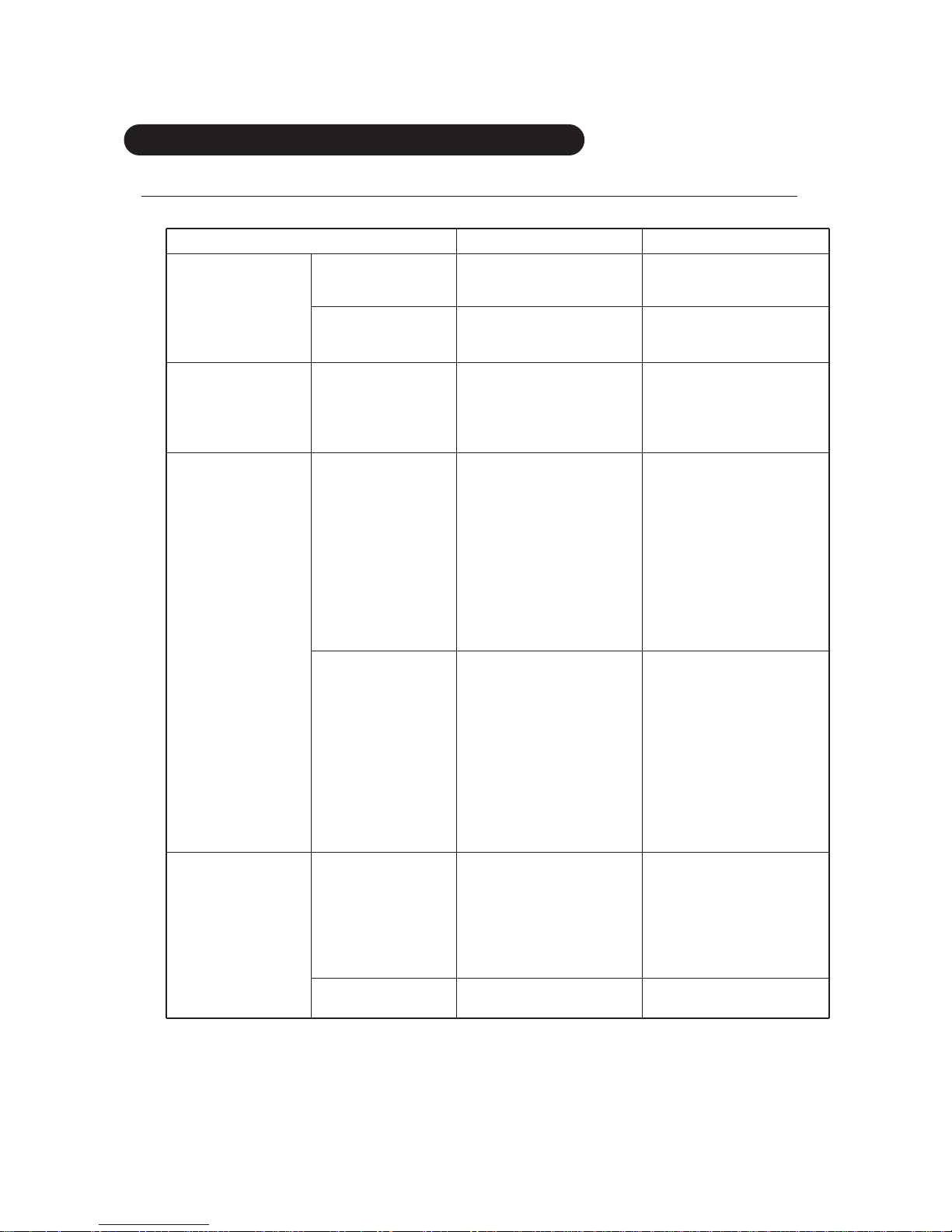
1.2 APPLICATION MODEL
1.2.1
COMPACT SII, MII & LI SERIES FOR 7,000 T O 17,000 BTU/h
CLASSIFICATION INDOOR UNIT OUTDOOR UNIT
AS ∗7ASC-W AO ∗7ASC
Cooling AS
∗
7ASCCW AO ∗7ASCC
7,000 BTU/h AS ∗7ASD-W AO ∗7ASD
SII-SERIES
Reverse cycle
AS
∗
7RSC-W AO ∗7RSC
AS
∗
7RSCCW AO ∗7RSCC
(Cool & Heat)
AS
∗
7RSD-W AO ∗7RSD
ASC-202EA AOC-202EA
ASC-202A AOC-202A
8,000BTU/h
Cooling
ASC-202B AOC-202B
MII-SERIES ASC-202C AOC-202C
ASC-202D AOC-202D
ASC8AYB-W AOC8AGBE
AS
∗
9ASE-W AO ∗9ANE
AS
∗
9ASF-W AO ∗9ANF
AS
∗
9ASG-W AO ∗9ANG
AS
∗
9ASECW AO ∗9ANEC
AS
∗
9ASFCW AO ∗9ANFC
AS
∗
9ASGCW AO ∗9ANGC
Cooling AS
∗
9ASHCW AO ∗9ANHC
AS
∗
9ASMCW AO ∗9ANMC
ASB9ASB-W AOB9ASB
ASA9ASECW AOA9ANEC
FAS25ASAW FAO25ASA
9,000BTU/h ASZ9ASBCW AOZ9ASBC
MII-SERIES
AS
∗
9RSE-W AO ∗9RSE
AS
∗
9RSF-W AO ∗9RSF
AS
∗
9RSG-W AO ∗9RSG
AS
∗
9RSECW AO ∗9RNEC
AS
∗
9RSFCW AO ∗9RSFC
Reverse Cycle
AS
∗
9RSGCW AO ∗9RSGC
AS
∗
9RSHCW AO ∗9RSHC
(Cool & Heat)
AS
∗
9RSMCW AO ∗9RSMC
ASB9RSACW AOB9RSNC
ASB9RSBCW AOB9RNBC
FAS25RSAW FAO25RSA
FAS25RSBW FAO25RSB
ASQ9RSDCW AOQ9RSDC
ASC-252EA AOC-252EA
ASC-252A AOC-252A
ASC-252B AOC-252B
Cooling
ASC-252C AOC-252C
10,000BTU/h
ASC-252D AOC-252D
ASC10AYB-W AOC10AGBE
MII-SERIES
AS
∗
10FSA-W AO ∗10FSA
AS ∗10FSACW AO ∗10FSAC
Reverse cycle AS
∗
10USA-W AO ∗10USA
(Cool & Heat) AS
∗
10USACW AO ∗10USAC
Page 5
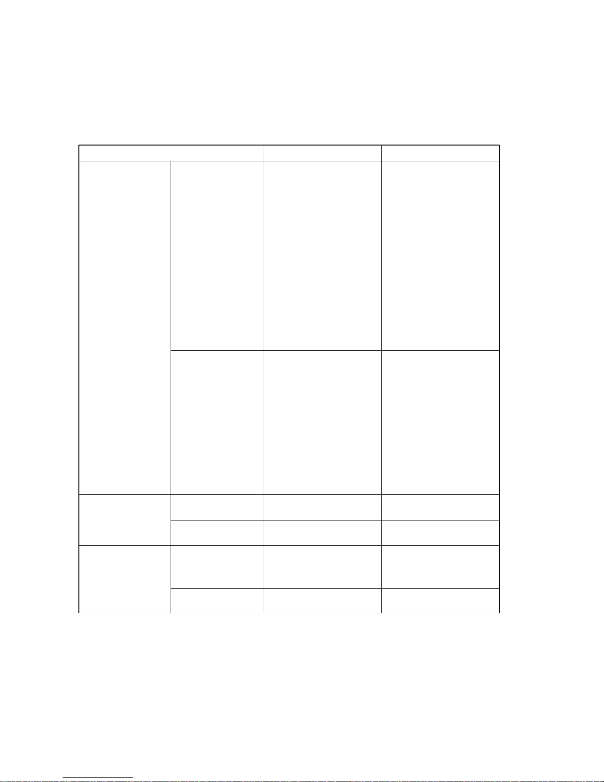
– 4 –
CLASSIFICATION INDOOR UNIT OUTDOOR UNIT
AS ∗12ASE-W AO ∗12ASE
AS
∗
12ASF-W AO ∗12ASF
AS
∗
12ASG AO ∗12ASG
AS
∗
12FSA-W AO ∗12FSA
AS
∗
12ASECW AO ∗12ASEC
AS
∗
12ASFCW AO ∗12ASFC
AS
∗
12ASGCW AO ∗12ASGC
AS
∗
12ASHCW AO ∗12ASHC
AS
∗
12FSACW AO ∗12FSAC
Cooling
AS
∗
12ASMCW AO ∗12ASMC
ASB12ASACW AOB12ASAC
ASB12ASB-W AOB12ARAE
ASB12ASBCW AOB12ARAE
ASB12ASCCW AOB12ASCC
ASZ12ASCCW AOZ12ASBC
ASA12ASECW AOA12ASEC
12,000BTU/h
FAS34ASAW FAO34ASA
ASQ12ASBCW AOQ12ASBC
MII-SERIES
ASU12ASNCW AOU12ASNC
ASH12ASECW AOH12ASEC
AS
∗
12RSE-W AO ∗12RSE
AS
∗
12RSF-W AO ∗12RSF
AS
∗
12RSG-W AO ∗12RSG
AS
∗
12USA-W AO ∗12USA
AS
∗
12RSECW AO ∗12RSEC
AS
∗
12RSFCW AO ∗12RSFC
Reverse cycle
AS
∗
12RSGCW AO ∗12RSGC
AS
∗
12RSHCW AO ∗12RSHC
(Cool & Heat)
AS
∗
12RSMCW AO ∗12RSMC
AS
∗
12USACW AO ∗12USAC
ASB12RSBCW AOB12RSBC
ASB12RSCCW AOB12RSCC
ASB12RSDCW AOB12RRAE
FAS34RSAW FAO34RSA
FAS34RSBW FAO34RSB
Cooling
AS
∗
14ASE-W AO ∗14AGD
14,000 BTU/h
AS
∗
14ASF-W AO ∗14AND
LI-SERIES
Reverse cycle AS
∗
14RSE-W AO ∗14RGD
(Cool & Heat) AS ∗14RSF-W AO ∗14RND
AS
∗
17ASE-W AO ∗17AB
Cooling
17,000 BTU/h
AS
∗
17ASH-W AO ∗17AN
LI-SERIES
AS
∗
17ASL-W
Reverse cycle AS
∗
17RSB-W AO ∗17RB
(Cool & Heat) AS
∗
17RSH-W AO ∗17RN
Page 6

– 5 –
INDOOR UNIT
CLASSIFICATION Wireless Wireless Wireless
(Handy/ OUTDOOR UNIT
(Handy) (Wall fixing)
Wall fixing universal)
20,000 BTU/h
24,000 BTU/h
30,000 BTU/h
Cooling
Reverse cycle
(Cool & Heat)
Cooling
Reverse cycle
(Cool & Heat)
Cooling
Reverse cycle
(Cool & Heat)
AS
∗
20AS
(ASC-502B)
AS
∗
20RS
AO
∗
20AW
AO
∗
20AZ
AO
∗
20AN
(AOC-502B)
AO
∗
20RW
AO
∗
20RZ
AO
∗
20RM
AS
∗
20AW
AS
∗
20RW
AS
∗
20AG
AS
∗
20RG
AS
∗
24AS
(ASC-602B)
AS
∗
24RS
AO
∗
24AW
AO
∗
24AB
AO
∗
24AN
(AOC-602B)
AO
∗
24RW
AO
∗
24RZ
AO
∗
24RM
AS
∗
24AW
AS
∗
24RW
AS
∗
24AG
AS
∗
24RG
AS ∗30AS
AS
∗
30RS
AS
∗
30AW
AS
∗
30RW
AS
∗
30AG
AS
∗
30RG
AO
∗
30AB
AO
∗
30RB
INDOOR UNIT
CLASSIFICATION Wireless Wireless Wireless
(Handy/ OUTDOOR UNIT
(Handy) (Wall fixing)
Wall fixing universal)
14,000 BTU/h
18,000 BTU/h
24,000 BTU/h
Cooling
Reverse cycle
(Cool & Heat)
Cooling
Reverse cycle
(Cool & Heat)
Cooling
Reverse cycle
(Cool & Heat)
AB
∗
14AS
AB ∗14RS
AB ∗14AW
AB ∗14RW
AB ∗14AG
AB ∗14RG
AO ∗14AN
AO ∗14AG
AO
∗
14RN
AO ∗14RG
AB
∗
18AS
AB
∗
18RS
AB
∗
18AW
AB
∗
18RW
AB
∗
18AG
AB
∗
18RG
AO
∗
18AW
AO
∗
18AZ
AO
∗
18AN
AO
∗
18RW
AO
∗
18RZ
AO
∗
18RM
AB
∗
24AS
AB
∗
24RS
AB
∗
24AW
AB
∗
24RW
AB
∗
24AG
AB
∗
24RG
AO
∗
24AW
AO
∗
24AB
AO
∗
24AN
AO
∗
24RW
AO
∗
24RZ
AO
∗
24RM
1.2.3 FLOOR/CEILING UNIVERSAL TYPE
AB-SERIES FOR 14,000 TO 24,000 BTU/h
1.2.2 W ALL MOUNTED LARGE
AS-SERIES FOR 20,000 TO 30,000 BTU/h
Page 7
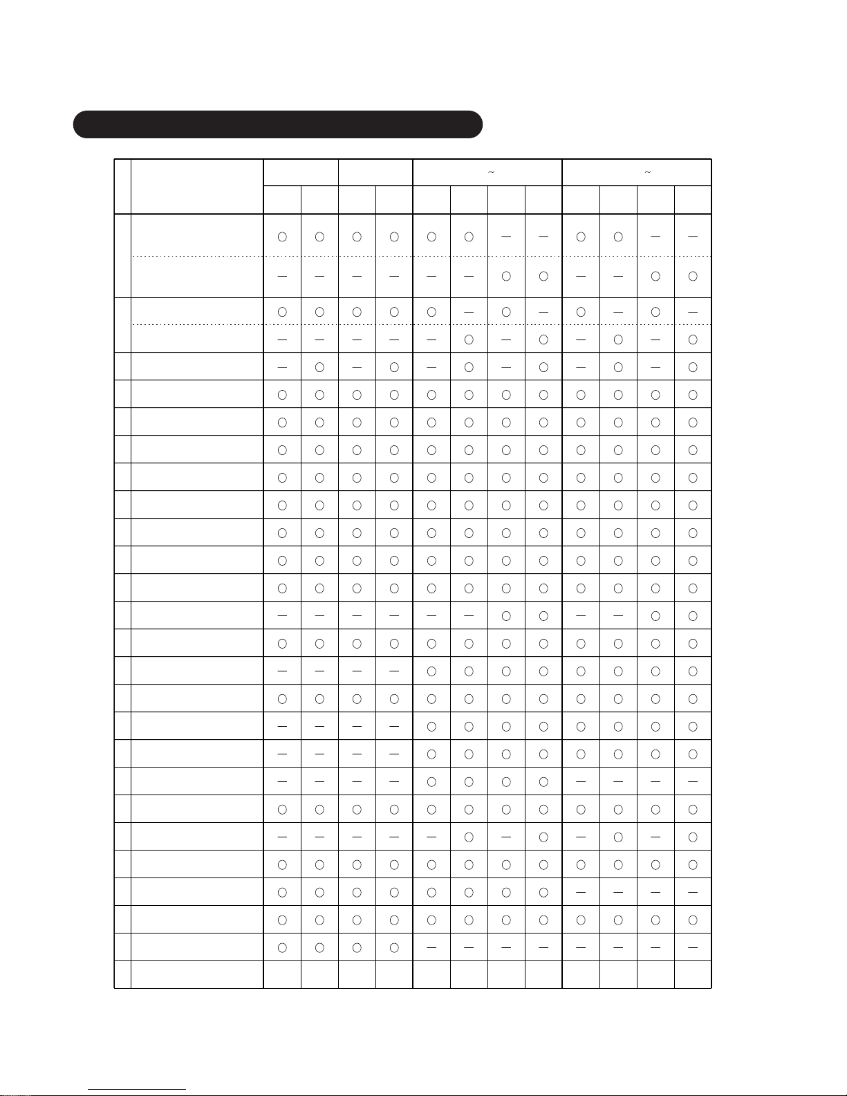
– 6 –
NOTE:
✽ 1 Models ASG30AS and ASY30AS have a No. 20 function.
✽ 2 Models AB ✽14RS have no No. 20 function.
✽ 3 Models AST9RSG and AST12RSG have a No. 2 function.
✽ 4 Models ASY9RSG and ASY12RSG have a No. 18 function.
No.
1
2
3
4
5
6
7
8
9
10
11
12
13
14
15
16
17
18
19
20
21
22
23
24
25 Others
Quiet
Auto-restart
Air purifying filter (optional)
Mold prevention filter
Cooling operation even at low
outdoor temperature (0˚C)
Automatic shut flaps
Linked power diffuser
Super vane
Horizontal air flow swing
operation
Vertical air flow swing
operation
Horizontal air direction
adjustment
Vertical air direction adjustment
Energy save operation
Program timer
Sleep timer
OFF timer
Nice morning timer (ON timer)
Auto fan speed
Fan operation
Dry operation
Cooling operation
Heating operation (reverse cycle)
Auto changeover operation
Automatic operation
Wireless remote control unit
• Handy type
Wireless remote control unit
• Wall fixing type
ITEM
Cooling
only
Reverse
cycle
Cooling
only
Reverse
cycle
Cooling
only
Reverse
cycle
Cooling
only
Reverse
cycle
Cooling
only
Reverse
cycle
Cooling
only
Reverse
cycle
COMPACT S
II
-type Wall mounted AS ✽ 20 30,000 BTU/h -type
FLOOR/CEILING AB
✽
14 24,000 BTU/h -type
COMPACT M
II
-type
✽3
✽1 ✽2 ✽1 ✽2 ✽2 ✽2
( ) ( ) ( ) ( ) ( ) ( ) ( ) ( )
✽4
1.3 FEATURES OF EACH MODEL
Page 8
– 7 –
+
+
-
-
CLOCK
START/STOP
AIR / LOW DIRECTION
+
-
MASTER
CONTROL
SET
TIMPL
SET
TIMPL
FAN
CONTROL
▼
1
1
2
3
8
9
7
10
11
6
5
4
12
14
13
CLOCK
SWING
LOUVER
AIR FLOW
DIRECTION
MASTER
CONTROL
SET
TIMPL
SET
TIMPL
FAN
CONTROL
START/STOP
+
-
SLEEP TIMER
15
16
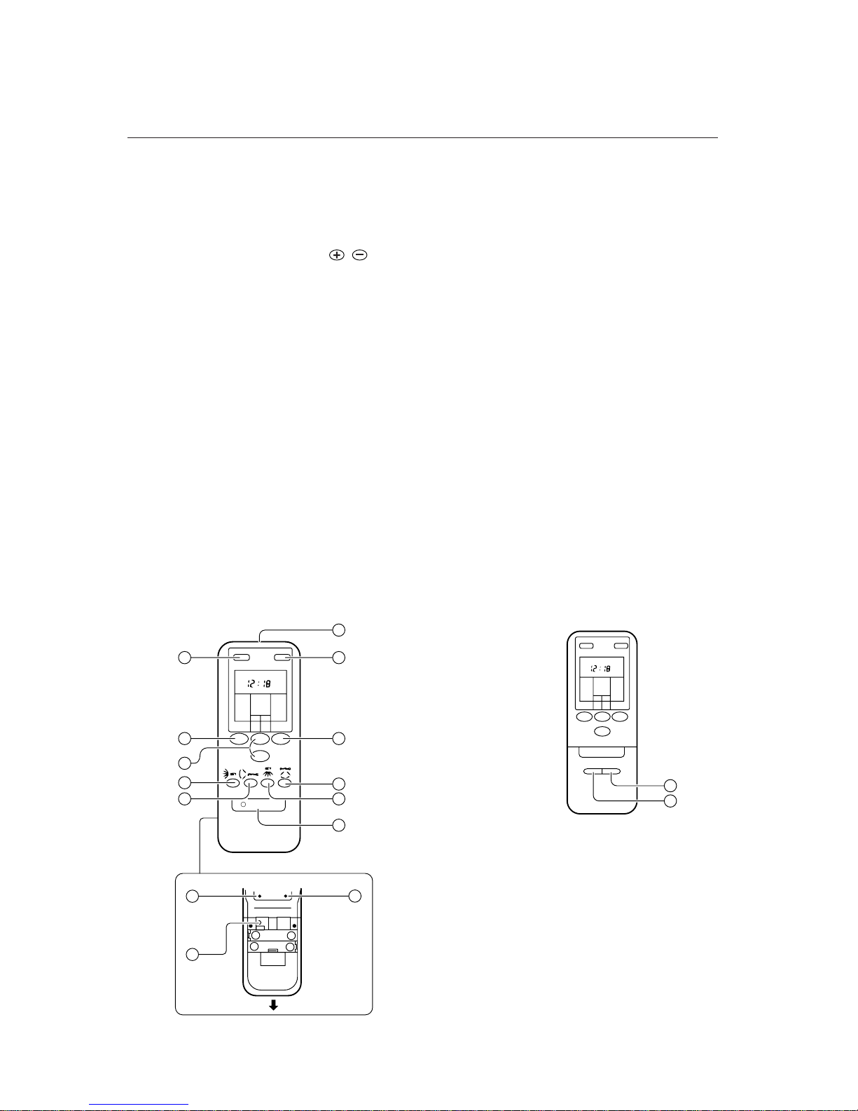
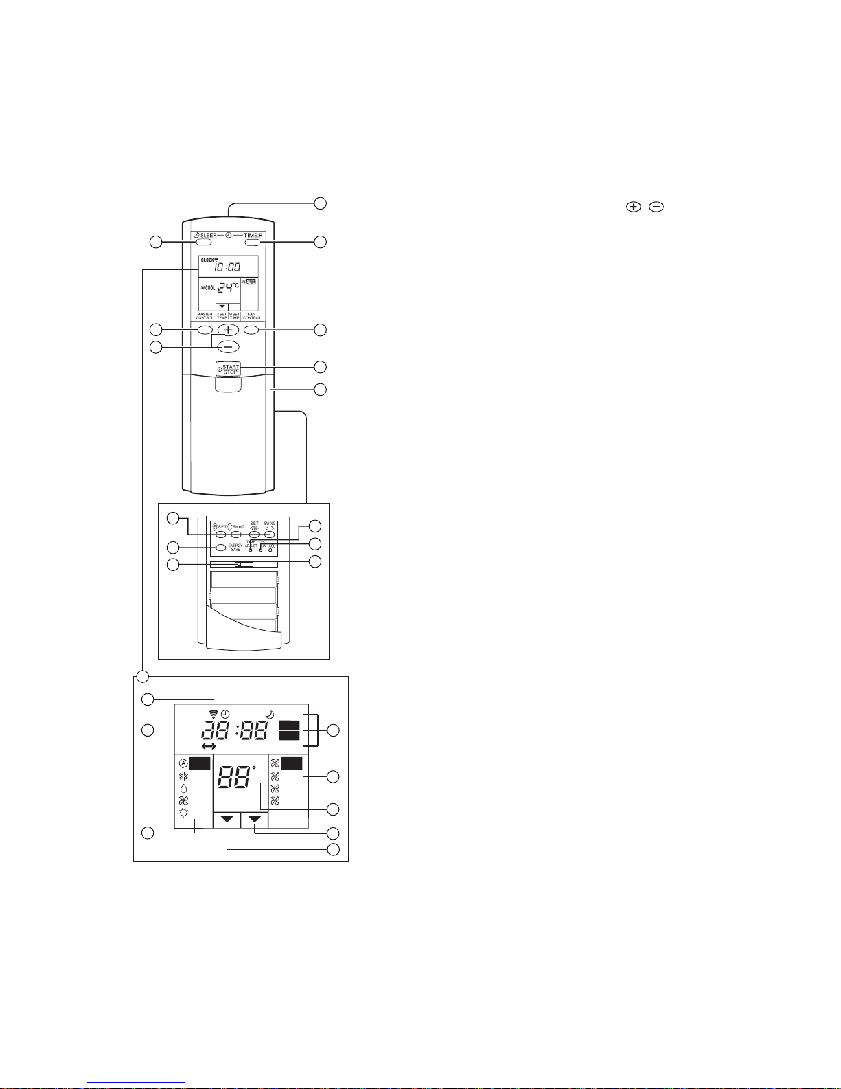
1.3.1 WIRELESS REMOTE CONTR OL UNIT (Hand y type)
q SLEEP button
w MASTER CONTROL button
e SET TEMP./SET TIME buttons ( / )
r Signal Transmitter
t TIMER button
y FAN CONTROL button
u START/STOP button
i AIRFLOW DIRECTION
VERTICAL SET Button
o AIRFLOW DIRECTION
VERTICAL SWING Button
!0 AIRFLOW DIRECTION
HORIZONTAL SET Button
!1 AIRFLOW DIRECTION
HORIZONTAL SWING Button
Rear Side
!2 TIME ADJUST button
!3 ACL button
(located inside battery compartment)
!4 TEST RUN button
• This button is used when installing the air conditioner, and should not be used under normal conditions, as it will cause the air conditioner's thermostat function to operate incorrectly.
• lf this button is pressed during normal operation,
the unit will switch to test operation mode, and the
Indoor Unit's OPERATION Indicator Lamp and
TIMER Indicator Lamp will begin to flash simultaneously.
• To stop the test operation mode, either press the
TEST RUN button once again, or press the
START/STOP button to stop the air conditioner.
!5 AIRFLOW DIRECTION
VERTICAL SET Button
!6 AIRFLOW DIRECTION
VERTICAL SWING Button
• Wireless type • Compact type SII, MII only
Page 9
– 8 –
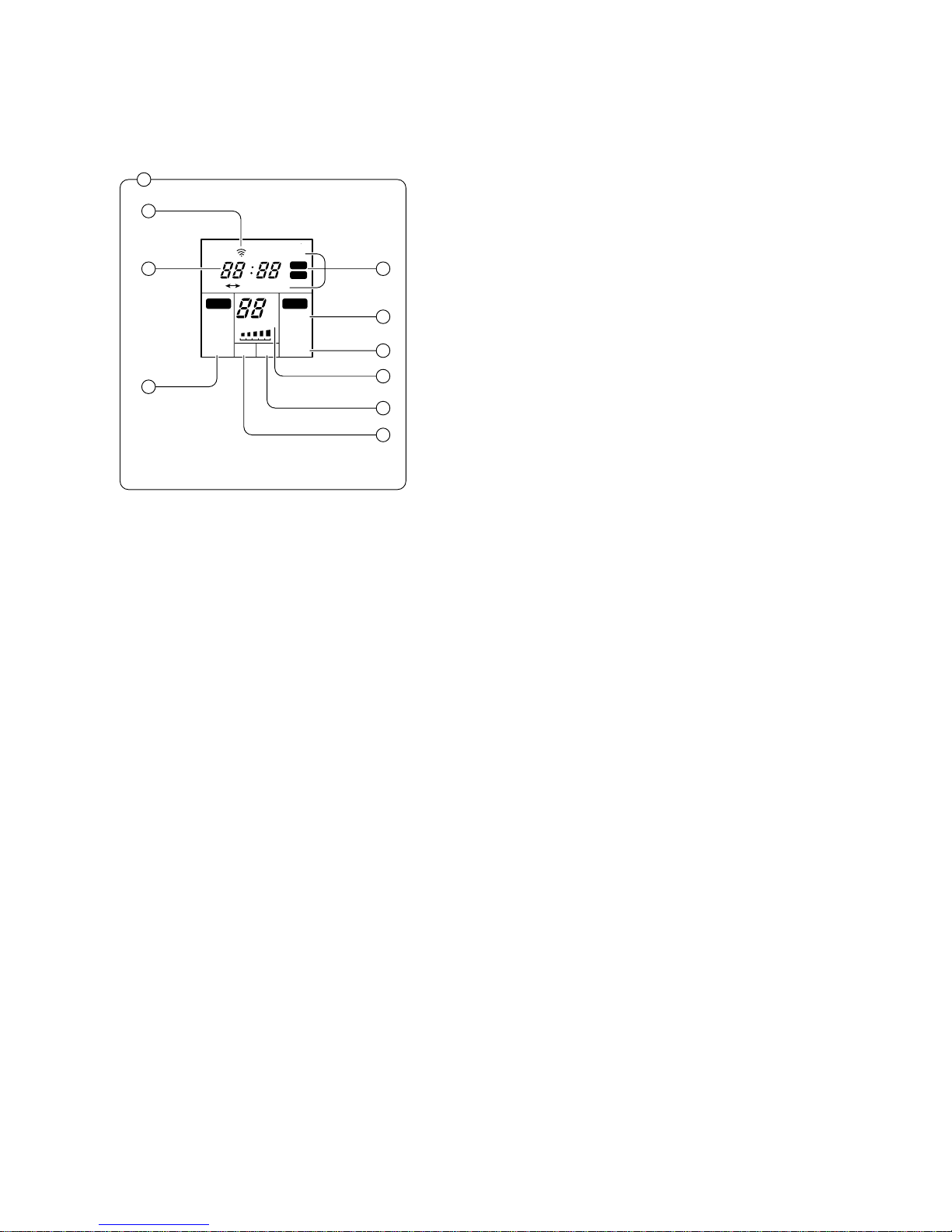
Remote Control Unit Display
!7 Remote Control Unit Display
!8 Transmit Indicator
!9 Clock Display
@0 Operating Mode Display
@1 Timer Mode Display
@2 Fan Speed Display
@3 Temperature Set Display
@4 Timer Set Indicator
@5 Temperature Set Indicator
@6 Compact type SII, MII only
LOW
MED
QUIET
HIGH
AUTOAUTO
COOL
HEAT
DRY
FAN
OFF
ON SLEEP
HM
°C
ON
OFF
CLOCK TIMER RESET
LOW HIGH
▲▲
17
18
19
20
21
22
23
24
25
26
Page 10
– 9 –
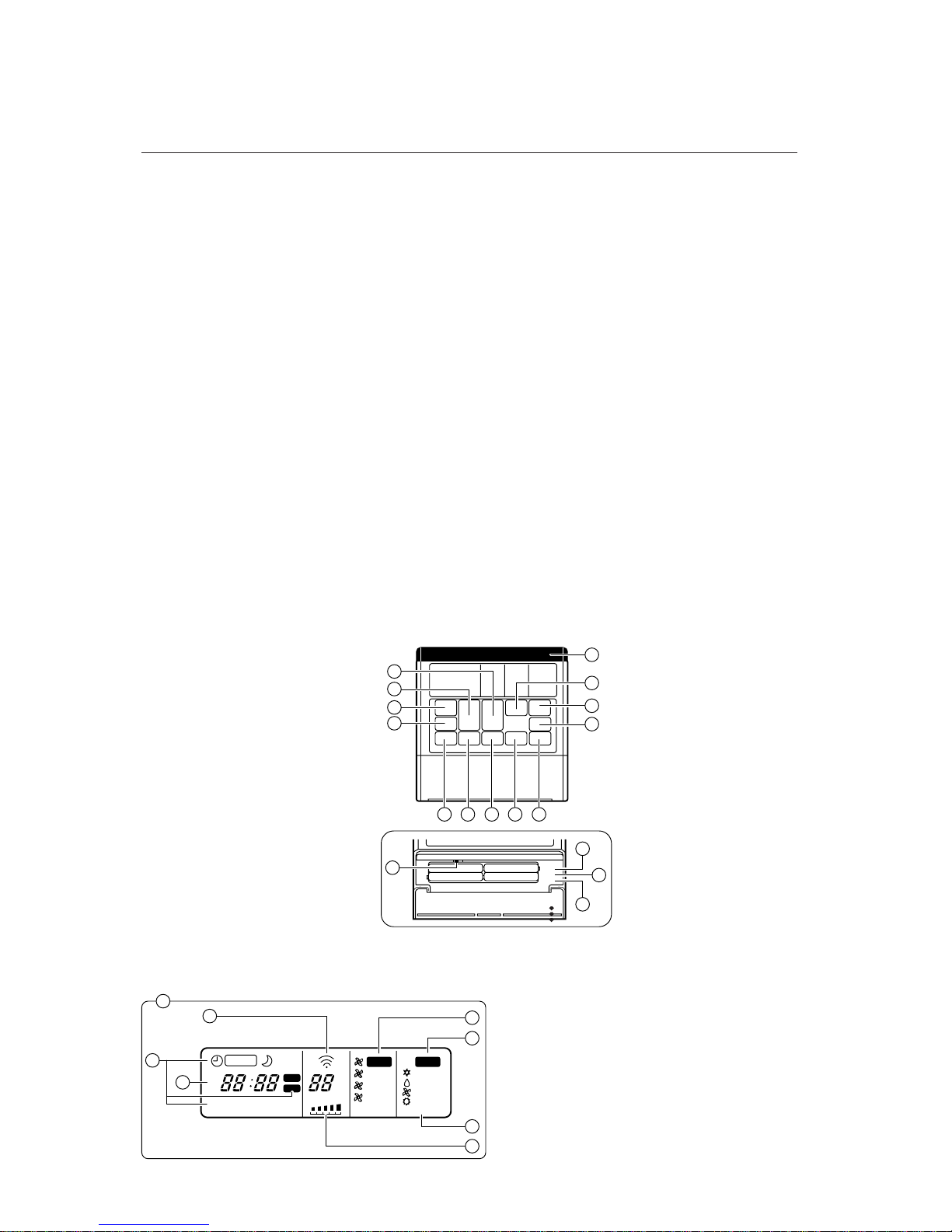
1.3.2
WIRELESS REMOTE CONTROL UNIT ( Wall fixing type )
q SLEEP button
w MASTER CONTROL button
e SET TIME buttons (▲ / ▼)
r SET TEMP. buttons (▲ / ▼)
t Signal Transmitter
y TIMER button
u FAN CONTROL button
i START/STOP button
o AIRFLOW DIRECTlON
VERTICAL SET Button
!0 AIRFLOW DIRECTION
VERTICAL SWING Button
!1 AIRFLOW DIRECTION
HORIZONTAL SET Button
!2 AIRFLOW DIRECTlON
HORIZONTAL SWING Button
!3 ENERGY SAVE Button
Inside of battery cover
!4 TIME ADJUST button
!5 ACL button
(located inside battery compartment)
!6 TEST RUN button
• This button is used when installing the air conditioner, and should not be used under normal conditions, as it will cause the air conditioner's thermostat function to operate incorrectly.
•
lf this button is pressed during normal operation, the
unit will switch to test operation mode, and the Indoor
Unit's OPERATION Indicator Lamp and TIMER
Indicator Lamp will begin to flash simultaneously.
• To stop the test operation mode, either press the
TEST RUN button once again, or press the
START/STOP button to stop the air conditioner.
!7 CODE CHANGE Switch
• Switching the remote controller code.
•
Use remote controller code A (on the leftmost side) to
operate the unit using the remote controller.
• When it is necessary to switch the remote controller code. contact a service technician since the
PCB remote controller code of the indoor unit
must also be switched.
4
5
7
2
13
9 10 11 12 8
3
6
1
17
16
15
14
Remote Control Unit Display
!8 Remote Controller Display
!9 Transmit lndicator
@0 Clock Display
@1 Operating Mode Display
@2 Timer Mode Display
@3 Fan Speed Display
@4 Temperature Set Display
@5 Energy Save Display
HM
LOW HIGH
LOW
MED
HIGH
COOL
HEAT
AUTO AUTO
(A)
°C
DAY
FAN
ENERGY SAVE
TIMER
SLEEP
OFF
ON
TIMER RESET
ON
OFF
▼
▼
18
19
22
20
23
21
25
24
Page 11
– 10 –
1.3.3 WIRELESS REMOTE CONTR OL UNIT
q SLEEP button
w MASTER CONTROL button
e SET TEMP./SET TIME buttons ( / )
r Signal Transmitter
t TIMER button
y FAN CONTROL button
u START/STOP button
i Battery compartment lid
Inside of the battery compartment lid
o AIRFLOW DIRECTION button
!0 ENERGY SAVE button
!1 CODE CHANGE (Slide Switch)
Switching the remote control unit code.
(Max. 4 units)
!2 TIME ADJUST button
!3 TEST RUN button
• This button is used when installing the air conditioner, and should not be used under normal
conditions, as it will cause the air conditioner's
thermostat function to operate incorrectly.
• lf this button is pressed during normal operation, the unit will switch to test operation mode,
and the Indoor Unit's OPERATION Indicator
Lamp and TIMER Indicator Lamp will begin to
flash simultaneously.
•
To stop the test operation mode, either press the
TEST RUN button once again, or press the
START/STOP button to stop the air conditioner.
!4 ACL button
!5 Remote Control Unit Display
!6 Transmit Indicator
!7 Clock Display
!8 Operating Mode Display
!9 Timer Mode Display
@0 Fan Speed Display
@1 Temperature Set Display
@2 Timer Set Indicator
@3 Temperature Set Indicator
A B C D
COOL
FAN
HEAT
AUTO
AUTO
HIGH
MED
LOW
TIMER
TIMER RESET
CLOCK
SLEEP
ENERGY SAVE
C
AM
PM
ON
OFF
OFF
ON
HM
DRY
1
2
3
4
5
6
7
8
9
10
11
12
13
14
15
16
17
18
19
20
21
22
23
Page 12
COOLING MODEL : This does not apply to the COMPACT type SII, MII.
• When the room temperature is 2°C higher than the set
temperature, the mode will switch between Cooling and
Drying.
• During Drying mode operation, FAN setting is switched to
LOW gentle cooling effect, and the room fan may stop
rotating temporarily.
• If the mode automatically selected by the unit is not what
you wish, select one of the mode operation (COOL, DRY,
FAN).
2°C
Setting temperature
Cooling Operation
Dry Operation
Thermostat control
– 11 –
1.3.4 A UTOMATIC OPERATION
COOLING MODEL : This applies to the COMPACT type SII and MII.
• Depending on the room temperature at the time operation
begins, the operating mode will be switched automatically
as ahown in the accompanying table.
Also, depending on the operating mode, the room temperature setting will cause the "standard" temperature to
be set as shown. The operating mode and standrad thermostat settings are selected automatically when operation begins.
• When automatic operation is initiated, the fan will run at
very low speed for about one minute while the unit
detects and selects the proper operating mode.
• Once the operating mode has been set, the mode will not
change even if the room temperature changes.
• If the START/STOP button is pressed to recommence
operation within two hours after stopping automatic operation, the unit will begin operating from the same mode as
before.
Actual Room Operating Mode Thermostat Setting
Temperature (standard setting)
30°C or above ➡ Cooling ➡ 27°C
27°C to 30°C ➡ Cooling ➡ 26°C
25°C to 27°C ➡ Dry ➡ 24°C
23°C to 25°C ➡ Dry ➡ 22°C
Below 23°C ➡ Dry ➡ 20°C
HEAT & COOL MODEL ( Reverse cycle )
• Depending on the room temperature at the time operation
begins, the operating mode will be switched automatically
as shown in the accompanying table.
Also, depending on the operating mode, the room temperature setting will cause the "standard" temperature to
be set as shown.
The operating mode and standrad thermostat settings are
selected automatically when operation begins.
• When automatic operation is initiated, the fan will run at
very low speed for about one minute while the unit
detects and selects the proper operating mode.
• Once the operating mode has been set, the mode will not
change even if the room temperature changes. However,
during the monitor operation mode, if the room temperature changes to below 22°C, the mode will automatically
switch to Heat, and when it rises above 24°C the mode
will automatically switch to Dry.
•
When in the monitor mode, the fan will operate very slowly.
• If the START/STOP button is pressed to recommence
operation within two hours after stopping automatic operation, the unit will begin operating from the same mode as
before.
Actual Room Operating Mode Thermostat Setting
Temperature (standard setting)
30°C or above ➡ Cooling ➡ 27°C
27°C to 30°C ➡ Cooling ➡ 26°C
25°C to 27°C ➡ Dry ➡ 24°C
22°C to 25°C ➡ Monitor
Below 22°C ➡ Heating ➡ 23°C
Page 13

– 12 –
1.3.5 A UTO CHANGEOVER OPERATION
HEAT & COOL MODEL (Reverse cycle)
• When AUTO CHANGEOVER operation is selected, the air conditioner selects the appropriate operation mode (Cooling or
Heating) in response to your room's temperature.
• When AUTO CHANGEOVER operation first selected, the fan will operate at very low speed for about one minute, during
which time the unit detects the room conditions and selects the proper operating mode.
• When the air conditioner has adjusted your room's temperature to near the thermostat setting, it will begin monitor operation. In
the monitor operation mode, the fan will operate at low speed. If the room temperature subsequently changes, the air conditioner will once again select the appropriate operation (Heating, Cooling) to adjust the temperature to the value set in the thermostat. (The monitor operation range is ±2°C relative to the thermostat setting.)
• If the mode automatically selected by the unit is not what you wish, select one of the mode operation
(HEAT, COOL, DRY, FAN).
1.3.6 HEATING OPERATION (REVERSE CYCLE)
• Use to warm your room.
• When Heating mode is selected, the air conditioner will operate at very low fan speed for about 3 to 5 minutes, after which it
will switch to the selected fan setting. This period of time is provided to allow the indoor unit to warm up before begin full operation.
• When the room temperature is very low, frost may form on the outside unit, and its performance may be reduced. In order to
remove such frost, the unit will automatically enter the defrost cycle from time to time. During Automatic Defrosting operation,
the OPERATION indicator lamp (red) will flash, and the heat operation will be interrupted.
1.3.7 COOLING OPERATION
• Use to cool your room.
1.3.8 DR Y OPERATION
• Use for gently cooling while dehumifdifying your room.
• You cannot heat the room during Dry mode.
• During Dry mode, the unit will operate at low speed; in
order to adjust room humidity, the indoor unit's fan may
stop from time to time. Also, the fan may operate at very
low speed when detecting room humidity.
• Then fan speed cannot be changed manually when Dry
mode has been selected.
During Heating mode :
Set the thermostat to a temperature setting that is higher
than the current room temperature. The Heating mode will
not operate if the thermostat is set lower than the actual
room temperature.
During Cooling/Dry mode :
Set the thermostat to a temperature setting that is lower
than the current room temperature. The Cooling and Dry
modes will not operate if the thermostat is set higher than
the actual room temperature (in Cooling mode, the fan
alone will operate).
During Fan mode :
You can not use the unit to heat and cool your room.
Page 14

– 13 –
1.3.9 FAN OPERATION
• Use to circulate the air throughout your room.
1.3.10 A UTO FAN SPEED
• When the FAN CONTROL switch is set to the AUTO position, the optimum fan speed will be selected automatically in accordance with room temperature and other conditions.
• During the dry mode, fan speed is set automatically and cannot be changed.
• The breeze is :
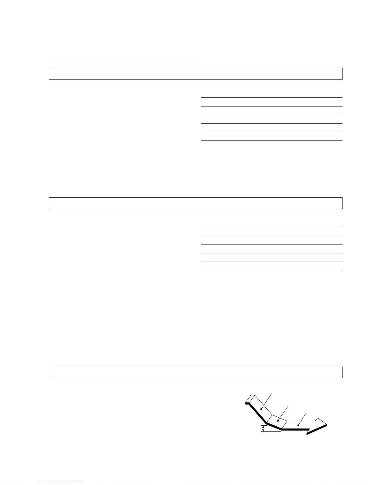
1.3.11 NICE MORNING TIMER (ON TIMER)
When the ON timer is used, the air conditioner not only starts at the set time, but also automatically starts before the set time
according to the difference between the room temperature and the set temperature so the room becomes the desired temperature at the set time. The time can be set in 5-minute steps.
HIGH 3°C higher
2°C higher
3°C or less
2°C or less MEDIUM
2°C or more
1°C or more
2°C or less
1°C or less LOW
Ta°CTa°CFan mode
Room temperature lowered Room temperature rised
(Room temperature and set temperature
difference = Ta°C)
Tp°C Fan mode
47
°C or more HIGH
41
°C to 47°C MEDIUM
41
°C or less LOW
(Indoor heat exchanger temperature = Tp
°C)
Cooling operation Heating operation
Room temperature and set
temperature difference
Operation start time
Started 20 minutes before set time
Started 15 minutes before set time
Started 10 minutes before set time
Over 10
°
C
5
°
C0 °C
Under 5
°
C
Cooling
Heating
Over 20
°
C
15
°
C0 °C
10
°
C5 °C
Under 10
°
C
Started 45 minutes before set time
Started 30 minutes before set time
Started 15 minutes before set time
Started 10 minutes before set time
Page 15
– 14 –
1.3.11 OFF TIMER
When the timer reaches the set time, the air conditioner will be turned off.
1.3.13 PROGRAM TIMER
Combines the OFF timer and the ON timer for one cycle. ( OFF ➱ ON or ON ➱ CFF )
Starts operation from the OFF timer or the ON timer, Whichever is closer to the current time.
1.3.14 ENERGY SAVE OPERATION
Wireless type (Wall fixing type) only
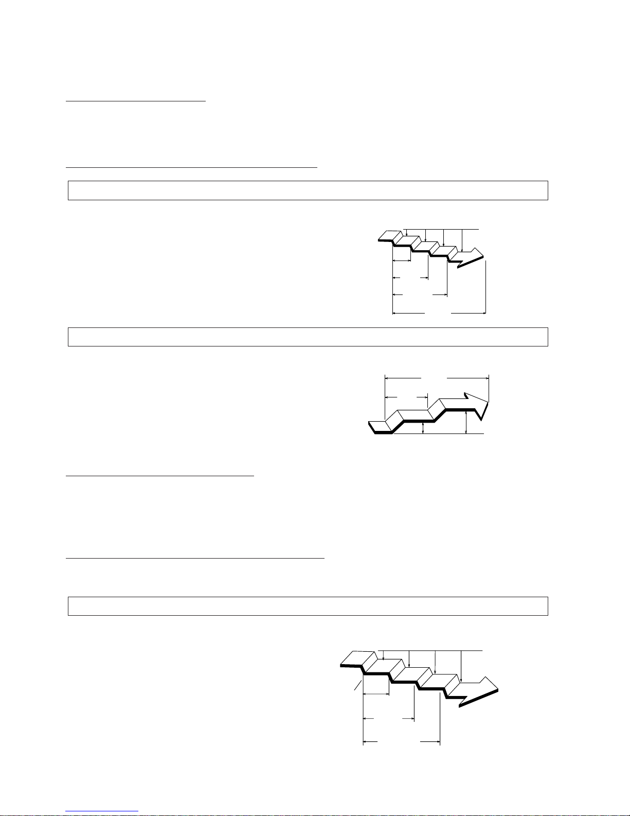
1.3.12 SLEEP TIMER OPERATION
During Heating operation [HEAT & COOL MODEL (Reverse cycle) only ] :
When the SLEEP timer is set, the thermostat setting is
automatically lowered 1°C every thirty minutes. When the
thermostat has been lowered a total of 4°C, the thermostat setting at that time is maintained until the set time has
elapsed, at which time the air conditioner automatically
turns off.
SLEEP timer setting
1°C
2°C
3°C
4°C
30
minutes
1 hour
1 hour
30 minutes
Set time
Setting temperature
During Cooling/Dry operation :
When the SLEEP timer is set, the thermostat setting is
auto-matically raised 1°C every sixty minutes. When the
thermostat has been raised a total of 2°C, the thermostat
setting at that time is maintained until the set time has
elapsed, at which time the air conditioner automatically
turns off.
During Heating operation [HEAT & COOL MODEL (Reverse cycle) only ] :
The thermostat temperature setting decreases by 1°C as
soon as the ENERGY SAVE button is pressed, and then
decreases by another 1°C every thirty minutes.
Afterwards, energy consumption is saved by continuing to
heat at a thermostat temperature of 4°C Iess than that
set.
SLEEP timer setting
1°C
2°C
1 hour
Set time
Setting temperature
ENERGY SAVE setting
1°C
2
°
C
3
°
C
4
°
C
30
minutes
1 hour
1 hour
30 minutes
ENERGY
SAVE ON
Setting temperature
Page 16
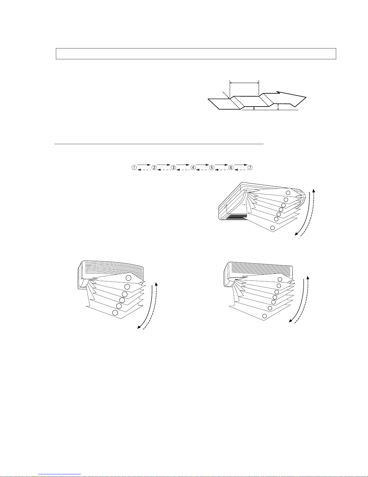
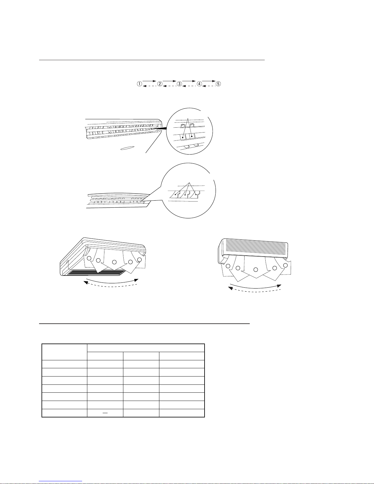
1.3.15 VERTICAL AIR DIRECTION ADJUSTMENT
Each time the button is pressed, the air direction range will change as follows :
– 15 –
During Cooling/Dry operation :
The thermostat temperature setting increases by 1°C as
soon as the ENERGY SAVE button is pressed, and then
increases by another 1°C after one hour has passed.
Afterwards, energy consumption is saved by continuing to
cool or dry at a thermostat temperature of 2°C more than
that set.
ENERGY SAVE setting
1 hour
ENERGY
SAVE ON
Set temperature
1˚C 2˚C
4
5
6
7
1
2
3
UNIVERSAL TYPE
7
6
5
4
3
2
1
WALL MOUNTED TYPE
1
2
3
4
5
6
COMPACT SII TYPE
Types of Airflow Direction Setting :
q,w,e,r : During Cooling/Dry Modes
t,y,u : During Heating mode
The Remote Control Unit's display does not change.
• Use the air direction adjustments within the ranges shown above.
• The vertical airflow direction is set automatically as shown, in accordance with the type of operation selected.
During Cooling/Dry mode : Horizontal flow q
During Heating mode : Downward flow u
• During AUTO mode operation, for the first minute after beginning operation, airflow will be horizontal q; the air direction can-
not be adjusted during this period.
Page 17
– 16 –
1.3.16 HORIZONTAL AIR DIRECTION ADJUSTMENT
Each time the button is pressed, the air direction range will change as follows:
1.3.17 VERTICAL AIRFLOW SWING OPERATION
• The range of swing is relative to the currently set airflow direction.
The Remote Controller's display does not change.
• Use the air direction adjustments within the ranges shown above.
• If the swing range is not as desired, use the Remote Control Unit's AIRFLOW DIRECTION VERTICAL SET button to change
the range of swing.
• The SWING Operation may stop temporarily when the air conditioner's fan is not operating, or when operating at very low
speeds.
• During use of the Cooling and Dry modes, do not set the Air UP/DOWN Direction Flaps, in the Heating range (t to u) for long
periods of time, since water vapor may condense near the outlet louvers and drops of water may drip from the air conditioner.
RIGHT/LEFT Air Direction Louvers
RIGHT/LEFT Air Direction Louvers
1
2
3
4
5
1
5
2 4
3
Airflow direction set
Range of swing
q
q to wq to e
q to e
w to e
r to t
r to y
t to yt to u
y to uq to u (All range)
t to u
r to ur to u
e to ye to y
w to tw to t
q to rq to r
q to e
w
e
r
t
y
u
SII Series MII Series
AS&AB Series
UNIVERSAL TYPE WALL MOUNTED TYPE
Page 18
– 17 –
1.3.18 HORIZONTAL AIRFLOW SWING OPERATION
• The range of swing is relative to the currently set airflow direction.
• If the swing range is not as desired, use the Remote Control Unit's AIRFLOW DIRECTION HORIZONTAL SET button to
change the range of swing.
• The SWING Operation may stop temporarily when the air conditioner's fan is not operating, or when operating at very low
speeds.
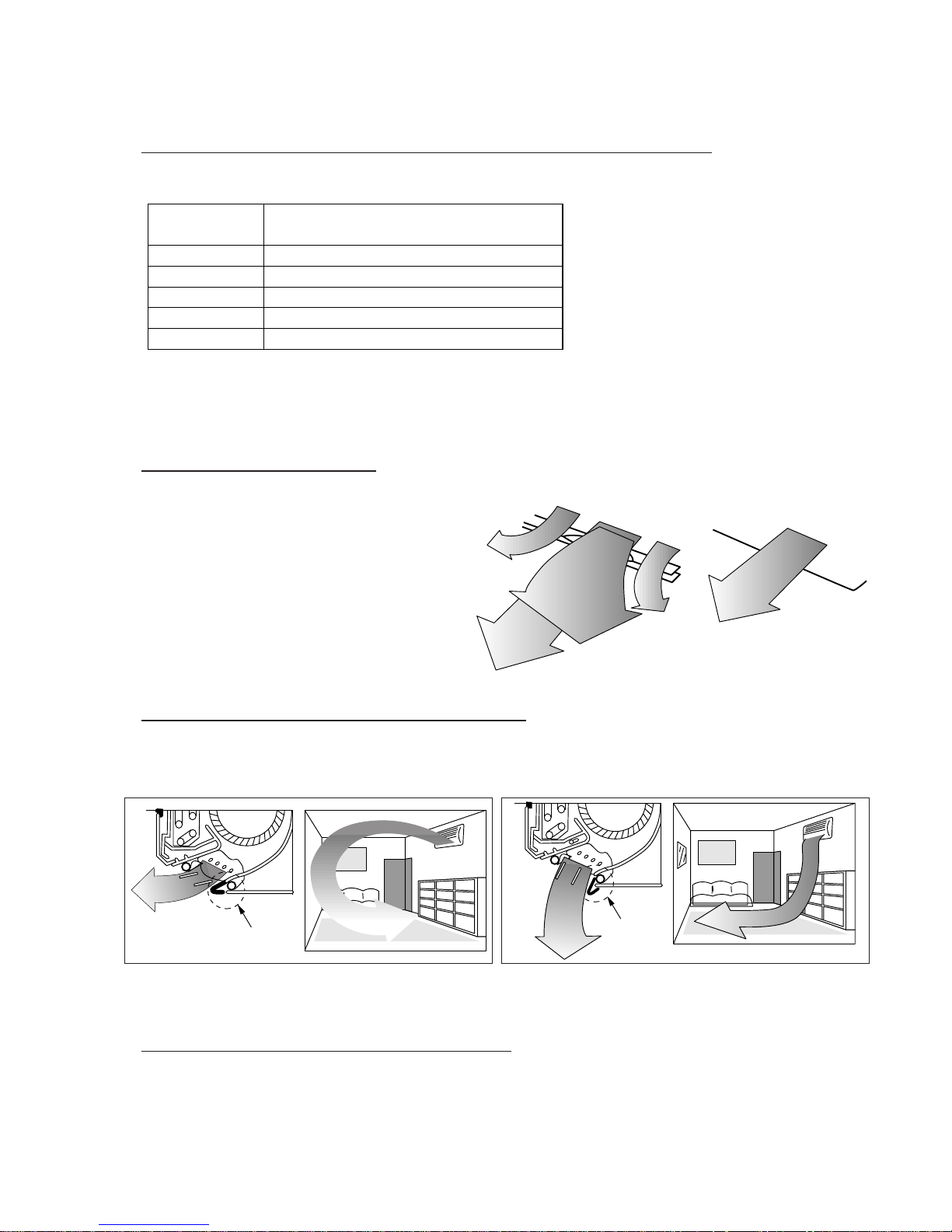
1.3.19 SUPER VANE
Our newly developed "Super Vane"configuration boosts airflow by sending cool air quickly to every corner of the room.
1.3.20 LINKED PO WER DIFFUSER
By means of our new design of "Power Diffuser" the floor level heating efficiency is considerably improved. By movement
of the up/down direction panels in conjunction with the power diffuser greater comfort can be obtained.
Airflow direction set
Range of swing
q
q to t (All range)
e to t
w to r
q to e
q to t (All range)
w
e
r
t
Linked Power
Diffuser
Linked Power
Diffuser
• Horizontal Cooling Airflow • Vertical Heating Airflow
1.3.21 A UTOMATIC SHUT FLAPS
• The upper and lower flaps shut automatically so that dust or foreign matter does not enter the inside of the unit, while the
unit halts.
• The unit looks simple on the outside, as the blow-out section of the air shuts.
Page 19
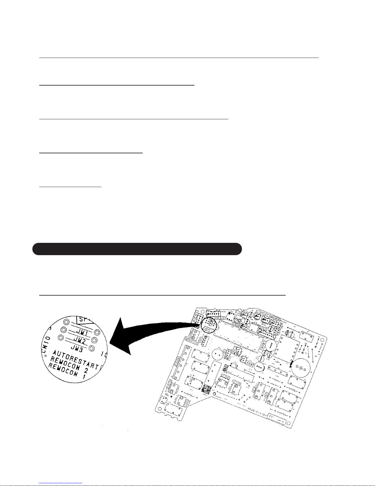
1.4 PRINTED WIRING BO ARD SETTINGS
<APPLICATION MODEL>
AS∗20A, 20R, 24A, 24R, 30A, 30R
AB∗14A, 14R, 18A, 18R, 24A, 24R
1.4.1 A UTO-RESTART & REMO TE CONTR OLLER CODE
– 18 –
1.3.22
COOLING OPERATION EVEN AT A LO W OUTDOOR TEMPERATURE
Cooling operation is possible down to 0°C.
1.3.23 MOLD PREVENTION FILTER
The air filter are specially treated with a mold inhibiting compound.
This stops mold and mildew from forming inside the indoor unit.
1.3.24 AIR PURIFYING FILTER (OPTIONAL)
The electrostatic filter removes dust and minute particles to purify the air in a room.
This is perfect for smokers and for people with allergies during pollen season.
1.3.25 A UTO RESTART
Auto restart function makes the unit to restart automatically in the same operating mode as before after recovery from
stoppage due to a temporary power failure.
1.3.26 QUIET
The large-diameter cross fan can send a larger volume of air while turning more slowly than before. Through the air suction from the top, smooth airflow and center mount structure, ultimate quietness has been realized while maintaining the
ample air volume and speed.
Page 20
– 19 –
✩ Confirm the remote controller's "CODE CHANGE Switch"
selection and printed wiring board setting.
· If these are not confirmed, the remote controller cannot be
operated for the air conditioner.
Auto - Restart Enable (default)
Auto - Restart Disable
Remote - Controller Code-A (default)
Remote - Controller Code-B
Remote - Controller Code-C
Remote - Controller Code-D
Disconnect
JM1
JM2
Connect
Disconnect
Connect
Disconnect
JM3
Connect
Connect
Disconnect
Disconnect
Connect
✩
CODE CHANGE Switch
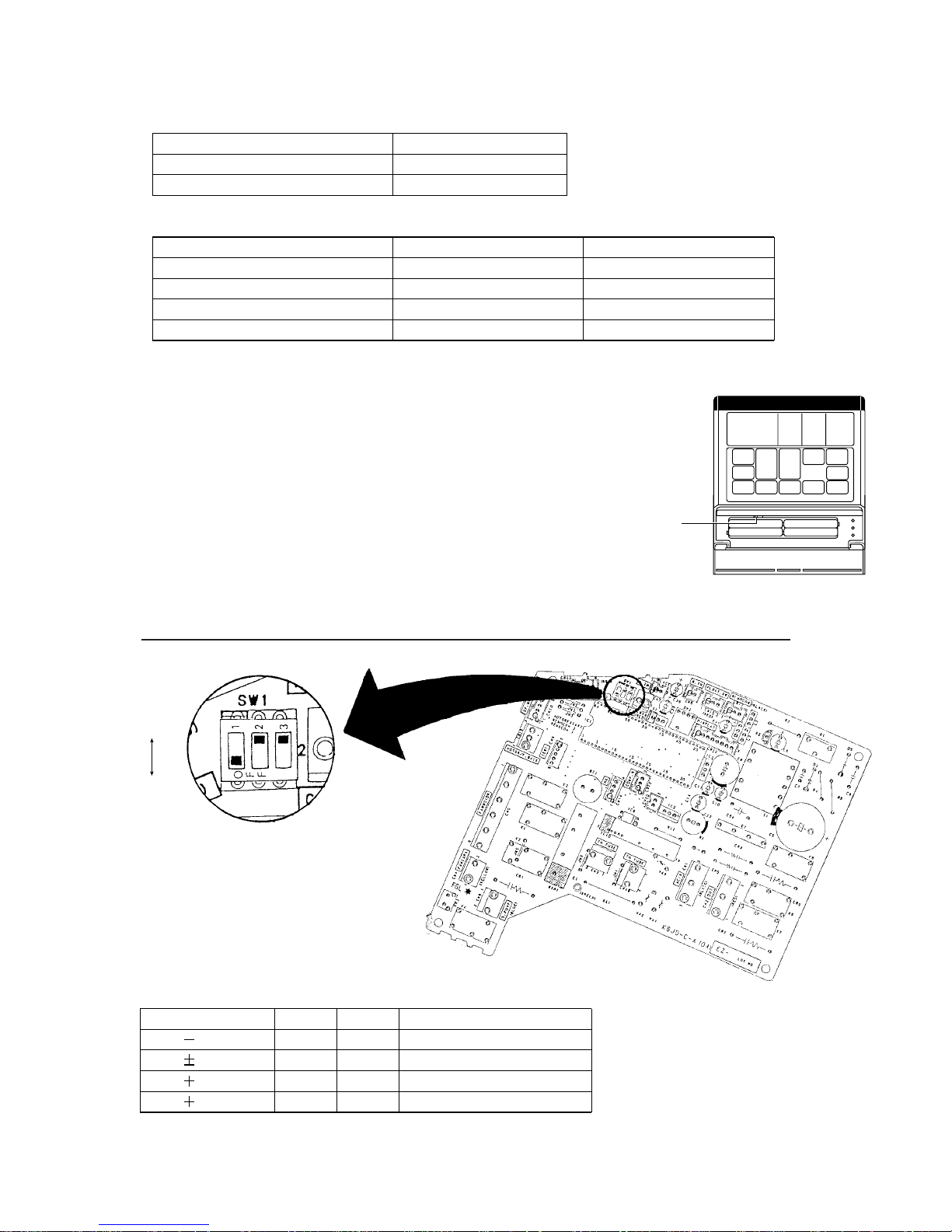
1.4.2
COMPENSATION (HEATING CORRECTION COEFFICIENT)
✩ The function of DIP1 does not work on AS and AB models.
Turn the DIP1 off anytime.
2
°
C
0
°
C
2
°
C
4
°
C(default)
Compensation
DIP2
ON
OFF
OFF
ON
DIP3
OFF
ON
OFF
ON
Application (AB model only)
for floor console
for under ceiling
ON
OFF
Page 21
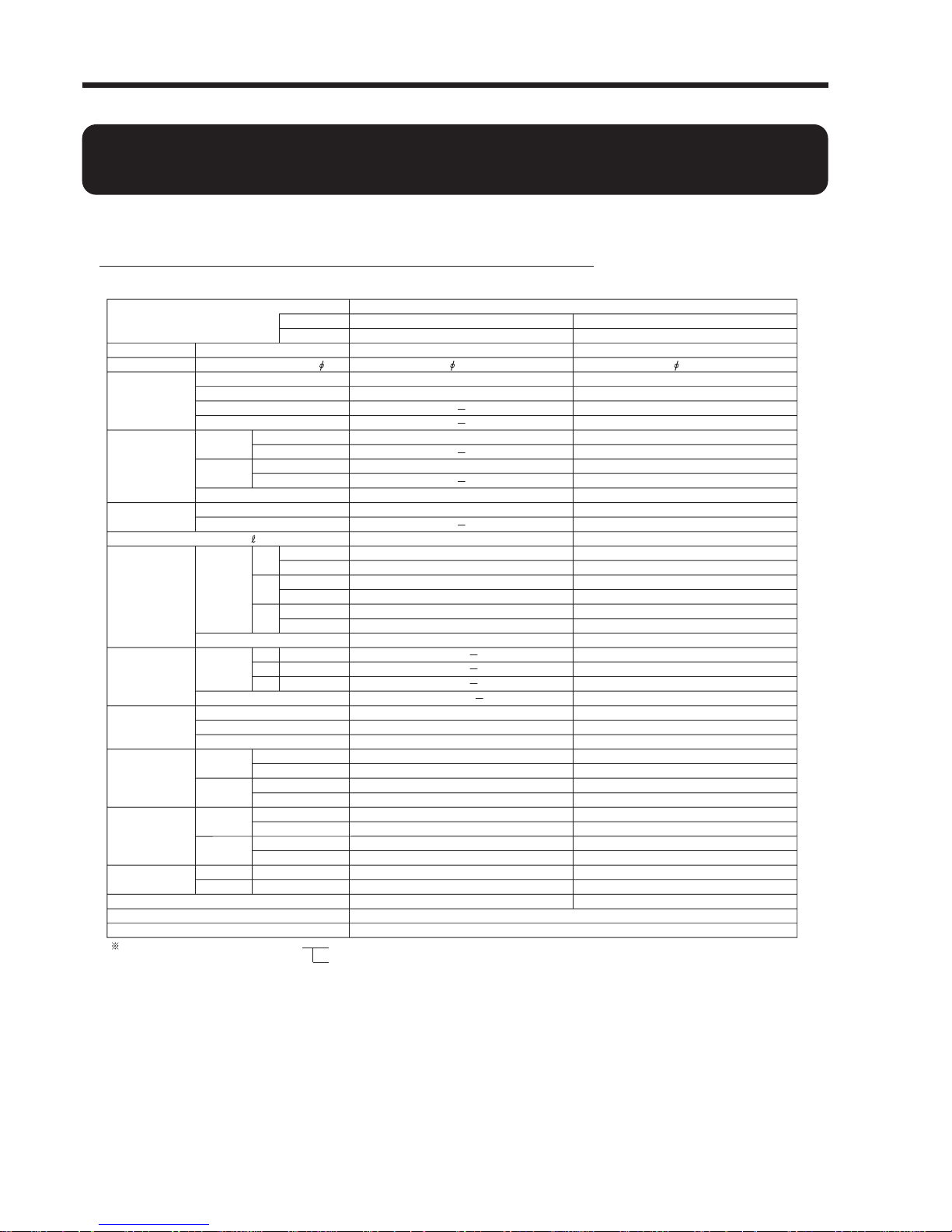
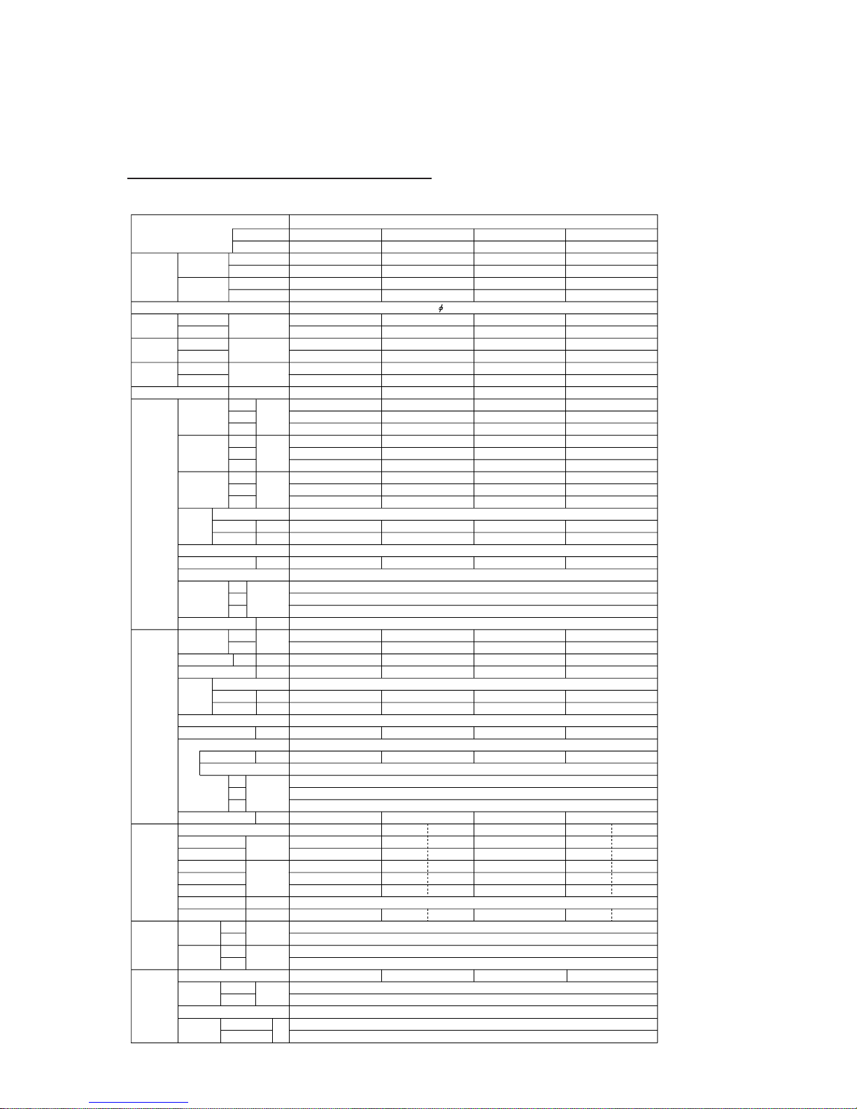
2. SPECIFICATIONS
MODEL
AS ✽ 7A
AO ✽ 7A
WALL MOUNTED TYPE COMPACT TYPE SII -CHASSIS (7,000 BTU/h)
Power Source
Phase-Cycles
Capacity
Moisture Removal
Air Circulation
Electrical Data
EER
Starting current
Heating
Heating
Cooling
Cooling
Cooling
Heating
Cooling
Heating
Ampacity
Cooling
Heating
Input watts
Outdoor unit
Indoor unit
[V]
-[Hz]
[kW]
[
BTU/h]
[kW]
[
BTU/h]
[A]
[A]
[kW]
[kW]
[A]
[
kW/kW]
[
kW/kW]
[
/hr]
[
m
3
/h]
[
C.F.M.
]
[
m
3
/h]
[
C.F.M.
]
[
m
3
/h]
[
C.F.M.
]
[m
3
/h]
[dB]
[dB]
[dB]
[dB]
[kW]
[W]
[mm]
[mm]
[mm]
[mm]
[kg]
[kg]
[kg]
[kg]
[mm]
[mm]
220 - 240
1 - 50
1.95 - 1.95
6,700 - 6,700
2.8 - 2.9
0.590 - 0.635
19
3.31 - 3.07
0.7 (1.5)
(Fan)
(H ✕ W ✕ D)
Operation Sound
Compressor
Dimensions
Weight
Pipe Size CD
Connection Pipe Set
Connection Method
Flare
White
Color
(Cool/Heat)
(Pints/hr)
340
200
315
185
290
170
1,330 - 1,400
37.0 /
35.0 /
33.0 /
42 - 43 /
Rotary
1.93
600
248 ✕ 808 ✕ 170
535 ✕ 650 ✕ 250
248 ✕ 852 ✕ 302
590 ✕ 725 ✕ 330
7.5
24
10.0
27
6.35
9.52
UTP-5FDG, UTP-7FDG
AS ✽ 7R
AO ✽ 7R
220 - 240
1 - 50
2.05 - 2.05
7,000 - 7,000
2.30 - 2.30
7,900 - 7,900
3.3 - 3.3
3.1 - 3.1
0.70 - 0.73
0.65 - 0.69
19
2.93 - 2.81
3.54 - 3.33
0.8 (1.8)
350
205
320
190
290
170
1,330 - 1,400
37.0 / 39.0
35.0 / 37.0
33.0 / 34.0
43 - 44 / 45 - 46
Rotary
2.29
700
248 ✕ 808 ✕ 170
535 ✕ 650 ✕ 250
248 ✕ 852 ✕ 302
590 ✕ 725 ✕ 330
7.5
25
10.0
28
6.35
9.52
UTP-5FKG, UTP-7FKG
Hi
Hi
Indoor
Indoor
Med
Med
Low
Low
Indoor
Outdoor
Indoor
Outdoor
Indoor
Outdoor
Indoor
Outdoor
Indoor
Outdoor
Outdoor
Outdoor
Net
Gross
Net
Gross
Gross
Liquid
Output watts
Type
Capacity
Permissible range of outdoor temperature Cooling : 18°C~43°C
Heating : -5°C
~
21°C
2.1.1 AS ✽ 7A / AO ✽ 7A, AS ✽ 7R / AO ✽ 7R
– 20 –
2.1 COMPACT SII, MII& LISERIES
(AS ✽ 7A, 7R, 9A, 9R, 12A, 12R, 14A, 14R, 17A, 17R)
Page 22
MODEL
Air Circulation
(Cool/Heat)
Models
Fan Guard
Indoor
WALL MOUNTED TYPE COMPACT TYPE MII - CHASSIS (9,000/17,000 BTU/h
)
Flare
White
AS ✽ 12R
AO ✽ 12R
220 - 240
1 - 50
3.45 - 3.50
11,800 - 12,000
4.00 - 4.10
13,600 - 14,000
5.8 - 5.9
5.7 - 5.9
1.22 - 1.27
1.19 - 1.27
35
2.83 - 2.76
3.36 - 3.23
1.8 (4.0)
Note : See the list shown
below.
1,365 - 1,475
40 - 40 / 39 - 39
39 - 39 / 36 - 36
37 - 37 / 31 - 31
45 - 46 / 46 - 47
Rotary
3.895 / 3.942
1,100
260 ✕ 815 ✕ 175
535 ✕ 665 ✕ 250
248 ✕ 866 ✕ 302
600 ✕ 785 ✕ 320
8
34
10
37
6.35
12.7
UTP-5FLG, UTP-7FLG
AS ✽ 9R
AO ✽ 9R
220 - 240
1 - 50
2.70 - 2.75
9,200 - 9,400
3.30 - 3.35
11,300 - 11,400
4.6 - 4.5
4.2 - 4.1
0.98 - 1.03
0.89 - 0.94
21
2.76 - 2.67
3.71 - 3.56
1.3 (2.9)
Note : See the list shown
below.
1,555 - 1,670
39 - 39 / 39 - 39
37 - 37 / 36 - 36
36 - 36 / 31 - 31
44 - 45 / 45 - 46
Rotary
3.045 / 3.070
950
260 5 815 ✕ 175
535 5 695 ✕ 250
248 5 866 ✕ 302
605 5 785 ✕ 320
8
30
10
33
6.35
9.52
UTP-5FKG, UTP-7FKG
AS ✽ 12A
AO ✽ 12A
220 - 240
1 - 50
3.45 - 3.50
11,800 - 12,000
—
—
6.0 - 6.0
—
1.255 - 1.315
—
35
2.75 - 2.66
—
1.8 (4.0)
475 - 500
280 - 294
420 - 460
247 - 271
370 - 415
218 - 244
1,555 - 1,670
39 - 40
37 - 38
35 - 37
44 - 45
Rotary
3.895 / 3.942
1,100
260 ✕ 815 ✕ 175
535 ✕ 695 ✕ 250
248 ✕ 866 ✕ 302
600 ✕ 785 ✕ 320
8
30
10
33
6.35
12.7
UTP-5FEG, UTP-7FEG
AS ✽ 9A
AO ✽ 9A
220 - 240
1 - 50
2.70 - 2.75
92,00 - 9,400
—
—
4.6 - 4.7
—
0.97 - 1.03
—
21
2.78 - 2.67
—
1.3 (2.9)
430 - 465
253 - 274
365 - 415
215 - 244
320 - 375
188 - 221
1,520 - 1,630
38 - 39
36 - 37
34 - 35
43 - 44
Rotary
3.005 / 3.035
850
260 ✕ 815 ✕ 175
535 ✕ 695 ✕ 250
248 ✕ 866 ✕ 302
600 ✕ 785 ✕ 320
8
27
10
30
6.35
9.52
UTP-5FDG, UTP-7FDG
With
480 - 480 / 495 - 495
282 - 282 / 291 - 291
445 - 445 / 430 - 430
262 - 262 / 253 - 253
420 - 420 / 375 - 375
247 - 247 / 221 - 221
Without
495 - 495 / 495 - 495
291 - 291 / 291 - 291
460 - 460 / 440 - 440
271 - 271 / 259 - 259
425 - 425 / 380 - 380
250 - 250 / 224 - 224
With
495 - 495 / 495 - 495
291 - 291 / 291 - 291
465 - 465 / 430 - 430
274 - 274 / 253 - 253
435 - 435 / 375 - 375
256 - 256 / 221 - 221
Without
510 - 510 / 510 - 510
300 - 300 / 300 - 300
475 - 475 / 440 - 440
280 - 280 / 259 - 259
450 - 450 / 380 - 380
265 - 265 / 224 - 224
Power Source
Phase-Cycles
Capacity
Electrical Data
EER
Moisture Removal
Air Circulation
(Cool/Heat)
Operation Sound
(Cool/Heat)
Compressor
Dimensions
(H ✕ W ✕ D)
Weight
Pipe Size CD
Connection Pipe Set
Connection Method
Color
Cooling
Cooling
Heating
Heating
Ampacity
Input watts
Starting Current
Cooling
Heating
Indoor
Outdoor
Indoor
Outdoor
Type
Capacity
Output watts
Net
Gross
Net
Gross
Liquid
Gross
Indoor unit
Outdoor unit
[V]
-[Hz]
[kW]
[BTU/h]
[kW]
[BTU/h]
Cooling [A]
Heating [A]
Cooling [A]
Heating [A]
[A]
[kW/kW]
[kW/kW]
[R/hr] (Pints/hr)
Hi [m
3
/h]
[C.F.M.]
Med [m
3
/h]
[C.F.M.]
Low [m
3
/h]
[C.F.M.]
[m
3
/h]
Hi [db]
Med [db]
Low [db]
[db]
[kW]
[W]
Indoor [mm]
Outdoor [mm]
Indoor [mm]
Outdoor [mm]
Indoor [kg]
Outdoor [kg]
Indoor [kg]
Outdoor [kg]
Indoor [mm]
Outdoor [mm]
Hi [m
3
/h]
[C.F.M.]
Med [m
3
/h]
[C.F.M.]
Low [m
3
/h]
[C.F.M.]
AS ✽ 9R AS ✽ 12R
Permissible range of outdoor temperature
With
540 - 540
318 - 318
500 - 500
294 - 294
460 - 460
270 - 270
Without
560 - 560
330 - 330
520 - 520
306 - 306
480 - 480
282 - 282
With
540 - 540
318 - 318
500 - 500
294 - 294
470 - 470
277 - 277
Without
560 - 560
330 - 330
520 - 520
306 - 306
480 - 480
282 - 282
AS ✽ 14A, R AS ✽ 17A, R
Note : See the list shown
below.
Note : See the list shown
below.
Cooling : 18°C
~
43°C (AS ✽ 9A, AS ✽ 9R, AS ✽ 12A, AS ✽ 12R, AS ✽ 14A, AS ✽ 14R, AS ✽ 17A / AO ✽ 17AN, AS ✽ 17R / AO ✽ 17RN), 18°~52°C (AS ✽ 17A / AO ✽ 17AB, AS ✽ 17R / AO ✽ 17RB)
Heating : -5°C~21° C (AS ✽ 9A, AS ✽ 9R, AS ✽ 12A, AS ✽ 12R), 0°C~21°C (AS ✽ 14A, AS ✽ 14R, AS ✽ 17A, AS ✽ 17R)
AS ✽ 17A
AO ✽ 17AB
220 - 240
1 - 50
4.50 - 4.60
15,400 - 15,700
—
—
9.9 - 10.3
—
2.00 - 2.10
—
55
2.40 - 2.28
—
2.1 (4.4)
2,590 - 2,590
41 - 41
39 - 39
37.5 - 37.5
55 - 55
Recipro
5.946 /
1,650
285 ✕ 900 ✕ 172
643 ✕ 840 ✕ 336
254 ✕ 951 ✕ 363
750 ✕ 959 ✕ 429
10
66
13
74
6.35
12.7
UTP-5FVG
AS ✽ 14A
AO ✽ 14A
220 - 240
1 - 50
3.85 - 4.00
13,100 - 13,700
—
—
7.6 - 7.8
—
1.62 - 1.72
—
41
2.38 - 2.33
—
1.6 (3.4)
1,600 - 1,600
40
39 - 39
37 - 37
50 - 50
Rotary
4.766 / 4.803
1,320
285 ✕ 900 ✕ 172
530 ✕ 750 ✕ 250
254 ✕ 951 ✕ 363
609 ✕ 882 ✕ 339
10
37
13
39
6.35
12.7
UTP-5FEG, UTP-7FEG
AS ✽ 14R
AO ✽ 14R
220 - 240
1 - 50
3.85 - 4.00
13,100 - 13,700
4.65 - 4.80
15,900 - 16,400
7.6 - 7.8
7.8 - 8.2
—
1.65 - 1.75
41
2.33 - 2.29
2.72 - 2.62
1.6 (3.4)
1,600 - 1,600
40 - 40
39 - 39
37 - 37
51 - 51 / 53 - 53
Rotary
4.766 / 4.803
1,320
285 ✕ 900 ✕ 172
530 ✕ 750 ✕ 250
254 ✕ 951 ✕ 363
609 ✕ 882 ✕ 339
10
36
13
40
6.35
12.7
UTP-5FLG, UTP-7FLG
AS ✽ 17R
AO ✽ 17RN
220 - 240
1 - 50
4.70 - 4.80
16,000 - 16,400
5.00 - 5.15
17,100 - 17,600
9.5 - 10.0
9.9 - 10.5
1.98 - 2.15
2.10 - 2.25
56
2.37 - 2.23
2.38 - 2.29
2.1 (4.4)
2,590 - 2,590
42 - 42
40 - 40
38 - 38 / 37 - 37
54.5 - 54.5 / 55.5 - 55.5
Rotary
6.245 / 6.280
1,700
285 ✕ 900 ✕ 172
643 ✕ 840 ✕ 338
254 ✕ 951 ✕ 363
750 ✕ 959 ✕ 429
10
59
13
67
6.35
12.7
UTP-5FWG
AS ✽ 17R
AO ✽ 17RB
220 - 240
1 - 50
4.40 - 4.50
15,000 - 15,400
5.00 - 5.15
17,100 - 17,600
10.1 - 10.5
10.5 - 10.9
2.02 - 2.10
2.08 - 2.19
55
2.37 - 2.23
2.38 - 2.29
2.1 (4.4)
2,590 - 2,590
42 - 42
40 - 40
38 - 38 / 37 - 37
54.5 - 54.5 / 55.5 - 55.5
Recipro
5.946 /
1,650
285 ✕ 900 ✕ 172
643 ✕ 840 ✕ 336
254 ✕ 951 ✕ 363
750 ✕ 959 ✕ 429
10
68
13
76
6.35
12.7
UTP-5FWG
AS ✽ 17A
AO ✽ 17AN
220 - 240
1 - 50
4.75 - 4.90
16,200 - 16,700
—
—
9.5 - 10.1
—
1.98 - 2.15
—
56
2.40 - 2.28
—
2.1 (4.4)
2,590 - 2,590
41 - 41
39 - 39
37.5 - 37.5
54.5 - 54.5
Rotary
6.245 / 6.280
1,700
285 ✕ 900 ✕ 172
643 ✕ 840 ✕ 338
254 ✕ 951 ✕ 363
750 ✕ 959 ✕ 429
10
55
13
63
6.35
12.7
UTP-5FWG
2.1.2 AS ✽9A, 9R, 12A, 12R, 14A, 14R, 17A, 17R / AO ✽ 9A, 9R, 12A, 12R, 14A, 14R, 17A, 17R
– 21 –
Page 23
– 22 –
MODEL
Permissible range of outdoor temperature
Cooling : 18°C
~
43°C
Heating : -5°C
~
21°C
WALL MOUNTED TYPE COMPACT TYPE MII - CHASSIS
Flare
White
ASQ12RAB-W
AOQ12RSB
220
1 - 50
3.30
11,300
4.00
13,600
5.8
5.8
1.21
1.21
35
2.73
3.31
1.8(4.0)
495 / 495
291 / 291
465 / 430
274 / 253
435 / 375
256 / 221
1,365 / 1,365
40 / 39
39 / 36
37 / 31
45 / 46
Rotary
3.895
1,100
260 ✕ 815 ✕ 175
535 ✕ 695 ✕ 250
248 ✕ 866 ✕ 302
605 ✕ 785 ✕ 320
8
34
10
37
6.35
12.7
UTP-5FLG, UTP-7FLG
ASQ9RSB-W
AOQ9RSB
220
1 - 50
2.65
9,000
3.30
11,300
4.6
4.2
0.98
0.89
21
2.70
3.71
1.3(2.9)
480 / 495
282 / 291
445 / 430
262 / 253
420 / 375
247 / 221
1,555 / 1,555
39 / 39
37 / 36
36 / 31
44 / 45
Rotary
3.045
950
260 ✕ 815 ✕ 175
535 ✕ 695 ✕ 250
248 ✕ 866 ✕ 302
605 ✕ 785 ✕ 320
8
30
10
33
6.35
9.52
UTP-5FKG, UTP-7FKG
ASQ12ASB-W
AOQ12ASB
220
1 - 50
3.35
11,400
—
—
6.0
—
1.255
—
35
2.67
—
1.8(4.0)
475
280
425
250
380
224
1,550
39
37
35
44
Rotary
3.895
1,100
260 ✕ 815 ✕ 175
535 ✕ 695 ✕ 250
248 ✕ 866 ✕ 302
605 ✕ 785 ✕ 320
8
30
10
33
6.35
12.7
UTP-5FEG, UTP-7FEG
ASQ9ASB-W
AOQ9ANB
220
1 - 50
2.70
9,200
—
—
4.9
—
1.03
—
21
2.62
—
1.3(2.9)
430
253
370
218
320
188
1,520
38
36
34
43
Rotary
3.045
850
260 ✕ 815 ✕ 175
535 ✕ 695 ✕ 250
248 ✕ 866 ✕ 302
605 ✕ 785 ✕ 320
8
27
10
30
6.35
9.52
UTP-5FDG, UTP-7FDG
Power Source
Phase-Cycles
Capacity
Electrical Data
EER
Moisture Removal
Air Circulation
(Cool/Heat)
Operation Sound
(Cool/Heat)
Compressor
Dimensions
(H ✕ W ✕ D)
Weight
Pipe Size CD
Connection Pipe Set
Connection Method
Color
Cooling
Cooling
Heating
Heating
Ampacity
Input watts
Starting Current
Cooling
Heating
Indoor
Outdoor
Indoor
Outdoor
Type
Capacity
Output watts
Net
Gross
Net
Gross
Liquid
Gross
Indoor unit
Outdoor unit
[V]
-[Hz]
[kW]
[BTU/h]
[kW]
[BTU/h]
Cooling [A]
Heating [A]
Cooling [A]
Heating [A]
[A]
[kW/kW]
[kW/kW]
[R/hr] (Pints/hr)
Hi [m
3
/h]
[C.F.M.]
Med [m
3
/h]
[C.F.M.]
Low [m
3
/h]
[C.F.M.]
[m
3
/h]
Hi [db]
Med [db]
Low [db]
[db]
[kW]
[W]
Indoor [mm]
Outdoor [mm]
Indoor [mm]
Outdoor [mm]
Indoor [kg]
Outdoor [kg]
Indoor [kg]
Outdoor [kg]
Indoor [mm]
Outdoor [mm]
2.1.3 ASQ9A, 9R, 12A, 12R / AOQ9A, 9R, 12A, 12R
Page 24
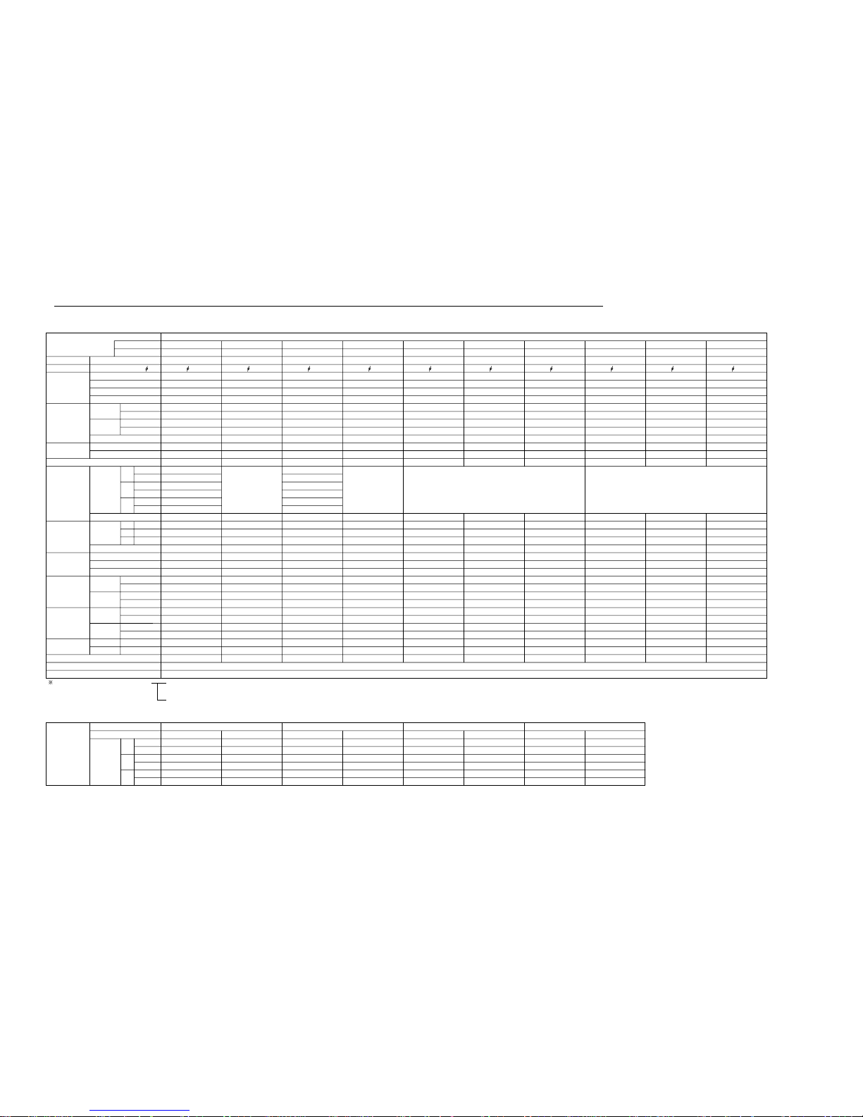
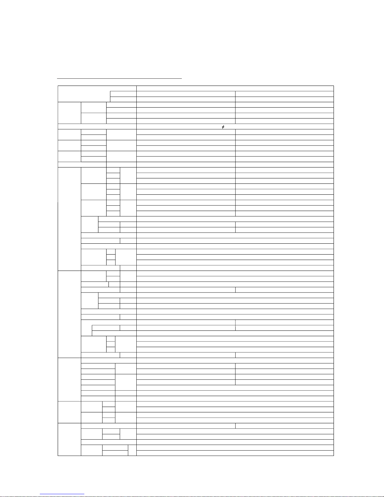
– 23 –
MODEL
Capacity
Power source
Total input
watts
Total
ampacity
EER
Starting current A
Cooling
Heating
kW
Cooling
Heating
A
Cooling
Heating
kW/kW
Cooling
Heating
kW
BTU/h
kW
BTU/h
Indoor
unit
Fan speedHiMed
Low
r.p.m.
Air
circulation
Hi
Med
Low
m
3
/h
Noise level
(Sound
pressure)
Heat
exchanger
Hi
Med
Low
dB(A)
Type
Face area
Fin inch
kg
r.p.m.
dB(A)
W
m
2
Fan type x Q’ty
Fan motor output
Operation control
Weight Net/Gross
D
Outdoor
unit
Fan speed
Hi
Low
Air circulation
Noise level
Hi m
3
/h
Fan motor output
W
Compressor type
W
kg
Motor output
Protection
Dimensions
H
W mm(inch)
D
Weight Net/Gross
Refrigerant
circuit
Suct. pressure
Operation mode
Disch. pressure
kg/cm
2
G
Discharge temp.
Condensing temp . ˚C
Suction temp.
Refr. pipe length m
˚C
Disch. air temp.
Condition
Indoor
entering
air temp.
Cool
Heat
Cool
Ourdoor
entering
air temp.
Heat
DB/WB
DB/WB
Piping
Pipe size
(O.D.)
Liquid
Gas
Connection method
Refrigerant charge kg(oz)
Between
Height
Pipe length
m
mm(inch)
H
Dimensions W mm(inch)
Heat
exchanger
Type
Face area
Fin inch
m
2
Fan type x Q’ty
Fan motor output
Outdoor unit
Indoor unit
WALL MOUNTED TYPE (WIRELESS)
AS ✽ 30R
AO ✽ 30RB
7.80 - 8.00
26,600 - 27,300
8.55- 8.80
29,200 - 30,000
3.20 - 3.30
2.90 - 3.00
15.4 - 15.9
13.9 - 14.4
2.44 - 2.42
2.95 - 2.93
80
1,280 - 1,340
1,120 - 1,200
970 - 1,050
1,000 - 1,060
860 - 930
730 - 810
47 - 48
44 - 45
39 - 40
0.274
17
32
690 - 730
410 - 450
3,100 - 3,320
53 - 54
0.726
14
63 x 1
85 / 97
Heating
19.0 - 19.0
4.3 - 4.3
89 - 90
48 - 48
-2 — -2
44 - 44
Cooling
17.6- 17.5
4.7 - 4.7
90 - 92
46.5 - 46.5
7 — 8
12 - 12
2.4 (84.7)
15
25
AS ✽ 30A
AO ✽ 30AB
8.05 - 8.20
27,500 - 28,000
—
—
3.20 - 3.30
—
15.4 - 15.9
—
2.52 - 2.48
—
80
1,280 - 1,340
1,120 - 1,200
970 - 1,050
1,000 - 1,060
860 - 930
730 - 810
47 - 48
44 - 45
39 - 40
0.274
17
32
690 - 730
410 - 450
3,100 - 3,320
53 - 54
0.726
14
63 x 1
84 / 96
Cooling
17.6- 17.5
4.7 - 4.7
90 - 92
46.5 - 46.5
7 — 8
12 - 12
2.3 (81.1)
15
30
Note : In the above square, put the letter T, Y, or G by a destination.
Propeller x 1
2,700
900 (35 - 7/16)
900 (35 - 7/16)
350 (13 - 25/32)
2,000
643 (25 - 5/16)
840 (33 - 1/16)
336 (13 - 1/4)
1,500
643 (25 - 5/16)
840 (33 - 1/16)
336 (13 - 1/4)
Plate fin coil
1 - 50Hz / 220-240V
Plate fin coil
Hermetic (Recipro)
Internal protector (OCR), High pressure relief valve
5
9.52 (3/8)
15.88 (5/8)
Flare
27°C / 19°C
20°C / 15°C
35°C / 24°C
7°C / 6°C
Cross flow fan x 2
Remote control
320 (12 - 5/8)
1,250 (49 - 3/16)
195 (7 - 11/16)
18 / 26
AS ✽ 24R
AO ✽ 24RZ
6.70 - 6.80
22,900 - 23,200
7.60 - 7.70
26,000 - 26,300
2.57 - 2.67
2.41 - 2.50
12.2 - 12.6
11.5 - 12.0
2.61 - 2.55
3.15 - 3.08
61
1,220 - 1,290
1,050 - 1,130
890 - 970
940 - 1,000
810 - 870
690 - 740
45 - 46
41 - 42
37 - 38
0.274
17
27
690 - 735
250 - 280
2,430 - 2,590
55 - 56
0.549
14
60
68 / 76
Heating
20.3 - 20.3
3.8 - 3.8
90 - 95
50 - 50
-2 — -2
43 - 43
Cooling
20.1- 19.8
4.8 - 4.8
98 - 101
51.5 - 51
9 — 11
12.5 - 12.5
2.07 (73.0)
AS ✽ 24A
AO ✽ 24AB
6.75 - 6.85
23,000 - 23,400
—
—
2.52 - 2.64
—
12.0 - 12.4
—
2.68 - 2.59
—
61
1,220 - 1,290
1,050 - 1,130
890 - 970
940 - 1,000
810 - 870
690 - 740
45 - 46
41 - 42
37 - 38
0.274
17
32
690 - 735
—
2,430 - 2,590
55 - 56
0.549
14
60
67 / 75
Cooling
20.1 - 19.8
4.7 - 4.7
91 - 94
51.5 - 51
4 — 4
12.5 - 12.5
1.95 (68.8)
AS ✽ 20R
AO ✽ 20RZ
5.55 - 5.70
19,000 - 19,500
5.65 - 5.80
19,300 - 19,800
2.10 - 2.20
1.80 - 1.90
9.9 - 9.3
8.5 - 8.0
2.64 - 2.59
3.14 - 3.05
50
1,060 - 1,110
890 - 970
740 - 810
820 - 860
690 - 740
570 - 620
41 - 42
37 - 38
33 - 34
0.274
17
20
690 - 735
250 - 280
2,430 - 2,590
55 - 56
0.549
14
60
68 / 76
Heating
17.0 - 16.9
4.2 - 4.2
82 - 85
45 - 51
1 — -1
40 - 40
Cooling
19.9- 19.7
5.2 - 5.2
95 - 97
51.5 - 51
7 — 7
13.5 - 13.5
1.80 (63.5)
AS ✽ 20A
AO ✽ 20AZ
5.55 - 5.70
19,000 - 19,500
—
—
2.10 - 2.20
—
9.9 - 9.3
—
2.64 - 2.59
—
50
1,060 - 1,110
890 - 970
740 - 810
820 - 860
690 - 740
570 - 620
41 - 42
37 - 38
33 - 34
0.274
17
32
690 - 735
—
2,430 - 2,590
55 - 56
0.563
17
60
66 / 74
Cooling
19.7 - 19.5
5.0 - 5.0
87 - 89
51.5 - 51
6 — 6
13.5 - 13.5
1.24 (43.7)
Propeller x 1
8
20
8
20
2.2.1 AS✽20A, 20R, 24A, 24R, 30A, 30R
2.2
WALL MOUNTED LARGE AS-SERIES (AS ✽ 20A, 20R, 24A, 24R, 30A, 30R)
Page 25
– 24 –
2.2.2
AS ✽ 20A, 20R, 24A, 24R
MODEL
AO
✽
20AN AO
✽
20RM AO
✽
24AN AO
✽
24RM
WALL MOUNTED TYPE (WIRELESS)
Capacity
Power source 1 - 50Hz / 220-240V
Total input
watts
Total
ampacity
EER
Starting current A
Cooling
Heating
kW
Cooling
Heating
A
Cooling
Heating
kW/kW
Cooling
Heating
kW
BTU/h
kW
BTU/h
5.80 - 5.90
19,800 - 20,100
—
—
2.11 - 2.27
—
10.3 - 11.0
—
2.75 - 2.60
—
50
1,110 - 1,160
920 - 1,000
790 - 850
820 - 860
690 - 740
570 - 620
41 - 42
37 - 38
33 - 34
0.274
17
—
20
690 - 735
2,430 - 2,590
54 - 55
0.563
17
60
250 - 280
690 - 735
2,430 - 2,590
55 - 56
0.549
14
60
—
690 - 735
2,430 - 2,590
55 - 56
0.549
14
60
250 - 280
690 - 735
2,430 - 2,590
55 - 56
0.549
14
60
8
20
Indoor
unit
Fan speedHiMed
Low
r.p.m.
Air
circulation
Hi
Med
Low
m
3
/h
Noise level
(Sound
pressure)
Heat
exchanger
Hi
Med
Low
dB(A)
Type
Face area
Fin inch
kg
r.p.m.
dB(A)
W
m
2
Fan type x Q’ty
Fan motor output
Operation control
Weight Net/Gross
D
Outdoor
unit
Fan speed
Hi
Low
Air circulation
Noise level
Hi m
3
/h
Fan motor output
W
Compressor type
W
kg
1,5001,665 2,0002,200Motor output
Protection
Dimensions
H
W mm(inch)
D
Internal protector (OCR)
643 (25 - 5/16)
840 (33 - 1/16)
336 (13 - 1/4)
Weight Net/Gross
Refrigerant
circuit
59 / 67
Cooling
21.1 - 21.1
Suct. pressure
Operation mode
Disch. pressure
kg/cm
2
G
Discharge temp.
Condensing temp . ˚C
Suction temp.
Refr. pipe length m
˚C
5.2 - 5.2
95 - 98
53 - 53
68 / 76
Cooling
21 - 21
5 - 5.05
93 - 96
52 - 52
6.2 — 7.79.4 — 10
Heating
17.8 - 18.8
3.45 - 3.55
76 - 81
46 - 46
-4 — -3.7 6 — 8
12.4 - 11.7 12.4 - 12.8 40 - 40
Disch. air temp.
Condition
Indoor
entering
air temp.
Cool
Heat
Cool
Ourdoor
entering
air temp.
Heat
DB/WB
DB/WB
27˚C / 19˚C
20˚C / 15˚C
35˚C / 24˚C
7˚C / 6˚C
Piping
1.5 (52.9) 1.95 (68.8) 1.87 (65.9) 2.12 (74.8)
Pipe size
(O.D.)
Liquid
Gas
Connection method
Refrigerant charge kg(oz)
Between
Height
Pipe length
m
mm(inch)
Flare
9.52 (3/8)
15.88 (5/8)
H
Dimensions W mm(inch)
Plate fin coil
Cross flow fan x 2
Remote control
Plate fin coil
195 (7 - 11/16)
18 / 25
Propeller x 1
Hermetic (Rotary)
5
320 (12 - 5/8)
1,250 (49 - 3/16)
Heat
exchanger
Type
Face area
Fin inch
m
2
Fan type x Q’ty
Fan motor output
68 / 76
Cooling
21 - 21
4.6 - 4.6
96 - 99
49 - 49
69 / 77
Cooling
20 - 20
4.6 - 4.6
95 - 97
51 - 51
5 — 8
Heating
19 - 19
3.7 - 3.8
71 - 72
49 - 49
-2 — -1.5
12.5 - 12.5 12.5 - 12.5 43 - 43
5.55 - 5.70
19,000 - 19,500
5.90 - 6.10
20,100 - 20,800
2.05 - 2.15
1.85 - 1.97
9.7 - 9.7
8.8 - 9.0
2.71 - 2.65
3.19 - 3.10
50
1,110 - 1,160
920 - 1,000
790 - 850
820 - 860
690 - 740
570 - 620
41 - 42
37 - 38
33 - 34
0.274
17
20
0.274
17
6.75 - 6.85
23,000 - 23,400
—
—
2.66 - 2.81
—
12.6 - 12.8
—
2.54 - 2.44
—
56
1,220 - 1,290
1,050 - 1,130
860 - 930
940 - 1,000
810 - 870
690 - 740
45 - 46
41 - 42
37 - 38
1,220 - 1,290
1,050 - 1,130
860 - 930
940 - 1,000
810 - 870
690 - 740
45 - 46
41 - 42
37 - 38
27
0.274
17
27
6.70 - 6.80
22,900 - 23,200
7.70 - 7.80
26,300 - 26,600
2.55 - 2.60
2.46 - 2.55
11.7 - 10.9
11.4 - 10.8
2.63 - 2.62
3.13 - 3.06
56
AS
✽
20A AS
✽
20R AS
✽
24A AS
✽
24R
Outdoor unit
Indoor unit
(Nontropicalized models)
Page 26

– 25 –
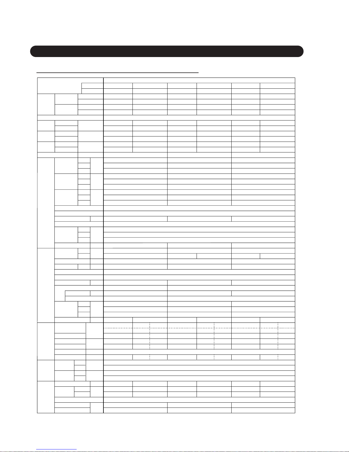
2.2.3
ASB20A, 20R, 24A, 24R, 30A, 30R
MODEL
ASB20A ASB20R ASB24A ASB24R ASB30A ASB30R
AOB20A AOB20R AOB24A AOB24R AOB30A AOB30R
WALL MOUNTED TYPE (WIRELESS)
Capacity
Power source 1 - 60Hz / 220V
Total input
watts
Total
ampacity
EER
Starting current A
Cooling
Heating
W
Cooling
Heating
A
Cooling
Heating
W/W
Cooling
Heating
W(SSA)
BTU/h
W
BTU/h
4,500
19,500
—
—
—
—
—
—
2,400
11.1
1.88
53
1,095
950
790
860
740
620
42
38
34
4,500
19,500
5,300
19,800
2,400
2,000
11.1
9.2
1.88
2.65
53
1,095
950
790
860
740
620
42
38
34
5,700
24,000
—
—
—
—
—
3,030
13.9
1.88
66
1,275
1,120
945
1,000
870
740
46
42
38
5,700
24,000
7,100
24,200
3,100
2,550
14.3
12.0
1.84
2.78
66
1,275
1,120
945
1,000
870
740
46
42
38
6,700
30,000
—
—
—
—
—
3,600
17.0
1.86
74
1,300
1,150
1,030
1,060
930
780
48
45
41
6,700
30,000
9,000
30,800
3,650
3,150
17.0
15.0
1.84
2.86
74
1,300
1,150
1,030
1,060
930
780
48
45
41
20 20 27 27 32 32
735
2,590
56
0.563
17
60
8
20
8
20
15
30
Indoor
unit
Fan speedHiMed
Low
r.p.m.
Air
circulation
Hi
Med
Low
m
3
/h
Noise level
(Sound
pressure)
Heat
exchanger
Hi
Med
Low
dB(A)
Type
Face area
Fin inch
kg
r.p.m.
dB(A)
W
m
2
Fan type x Q’ty
Fan motor output
Operation control
Weight Net/Gross
D
Outdoor
unit
Fan speed
Hi
Low
Air circulation
Noise level
Hi m
3
/h
Fan motor output
W
Compressor type
W
kg
1,500 1,900 3,000Motor output
Protection
Dimensions
H
W mm(inch)
D
Internal protector (OCR), High pressure relief valve
643 (25 - 5/16)
840 (33 - 1/16)
336 (13 - 1/4)
900 (35 - 7/16)
900 (35 - 7/16)
350 (13 - 25/32)
Weight Net/Gross
Refrigerant
circuit
66 / 74 68 / 76 67 / 75 68 / 76 84 / 96 85 / 97
Cooling Cooling Heating Cooling Cooling Heating Cooling Cooling Heating
25.1 24.9 17.4
Suct. pressure
Operation mode
Disch. pressure
kg/cm
2
G
Discharge temp.
Condensing temp . ˚C
Suction temp.
Refr. pipe length m
˚C
5.3 5.4 4.3
88 96 78
61
7
25.2
5.3
97
61.5
7
23.0
4.9
88
57
5
60.5 45.5
7-2
25.4 19.6
5.4 3.8
108 81
62.5749.5
-2
23.2 19.8
4.8 3.7
99 90
58
4
50
-3
5
14.5 14.5 40 14 14 42 13.5 13.5 44
Disch. air temp.
Condition
Indoor
entering
air temp.
Cool
Heat
Cool
Ourdoor
entering
air temp.
Heat
DB/WB
DB/WB
29˚C / 19˚C
20˚C / (15)˚C
46˚C / 24˚C
7˚C / 6˚C
Piping
1.29 (45.5) 1.69 (59.6) 1.75 (61.7) 2.07 (73.0) 2.3 (81.1) 2.45 (86.4)
Pipe size
(O.D.)
Liquid
Gas
Connection method
Refrigerant charge kg(oz)
Between
Height
Pipe length
m
mm(inch)
Flare
9.52 (3/8)
15.88 (5/8)
H
Dimensions W mm(inch)
Plate fin coil
0.274
17
Cross flow fan x 2
Remote control
195 (7 - 11/16)
18 / 16
Propeller x 1 Propeller x 1
Hermetic (Recipro)
Plate fin coil
320 (12 - 5/8)
1,250 (49 - 3/16)
Heat
exchanger
Type
Face area
Fin inch
m
2
Fan type x Q’ty
Fan motor output
—
735
2,590
56
—
735
2,590
56
—
735
2,590
56
—
730
3,320
55
—
730
3,320
55
0.726
14
63 x 1
0.549
14
0.549
14
0.549
17
0.726
14
60 60 60 63 x 1
Outdoor unit
Indoor unit
Page 27
– 26 –
2.2.2
ASC-502B, ASC-602B
MODEL
Capacity
Power source
Total input
watts
Total
ampacity
EER
Starting current A
Cooling
Heating
W
Cooling
Heating
A
Cooling
Heating
kcal/hW
Cooling
Heating
kcal/h
BTU/h
kcal/h
BTU/h
Indoor
unit
Fan speedHiMed
Low
r.p.m.
Air
circulation
Hi
Med
Low
m
3
/h
Noise level
(Sound
pressure)
Heat
exchanger
Hi
Med
Low
dB(A)
Type
Face area
Fin inch
kg
r.p.m.
dB(A)
W
m
2
Fan type x Q’ty
Fan motor output
Operation control
Weight Net/Gross
Outdoor
unit
Fan speed
Hi
Low
Air circulation
Noise level
Hi m
3
/h
Fan motor output
W
Compressor type
W
kg
Motor output
Protection
Dimensions
H
W
mm(inch)
D
H
W
mm(inch)
D
Weight Net/Gross
Refrigerant
circuit
Suct. pressure
Operation mode
Disch. pressure
kg/cm
2
G
Discharge temp.
Condensing temp .
˚C
Suction temp.
Refr. pipe length m
˚C
Disch. air temp.
Condition
Indoor
entering
air temp.
Cool
Heat
Cool
Ourdoor
entering
air temp.
Heat
DB/WB
DB/WB
Piping
Pipe size
(O.D.)
Liquid
Gas
Connection method
Refrigerant charger kg(oz)
Between
Height
Pipe length
m
mm(inch)
Dimensions
Heat
exchanger
Type
Face area
Fin inch
m
2
Fan type x Q’ty
ASC-502B
WALL MOUNTED TYPE (WIRELESS)
1 - 60Hz / 220V
2.19
—
55
1,275
65
1,120
945
1,000
870
740
46
42
38
0.274
1,095
950
790
860
740
620
42
38
34
0.274
17 17
18/26
5,000
19,850
—
—
2,280
—
10.6
—
ASC-602B
AOC-502B AOC-602B
6,000
23,820
—
—
2,600
—
12.0
—
2.31
—
Hermetic (Recipro)Hermetic (Rotary)
67/75
19.8
4.9
90
51
1,500 2,385
66/74
18.4
4.9
93
48
1.87(66.0) 2.02(71.3)
Cooling
27.0˚C / 19.5˚C
12
5
7
20.0˚C /(15.0)˚C
35.0˚C / 24.0˚C
7.0˚C / 6.0˚C
9.52(3/8)
15.88(5/8)
Flare
8
20
Plate fin coil
Cross flow fan x 2
20
Remote control
320(12-5/8)
1,250(49-3/16)
195(7-11/16)
—
Internal protector (OCR), High pressure relief valve
840(33-1/16)
643(25-5/16)
336(13-1/14)
735
2,590
55 56
Plate fin coil
0.549
14
Propeller x 1
60
Outdoor unit
Indoor unit
Page 28
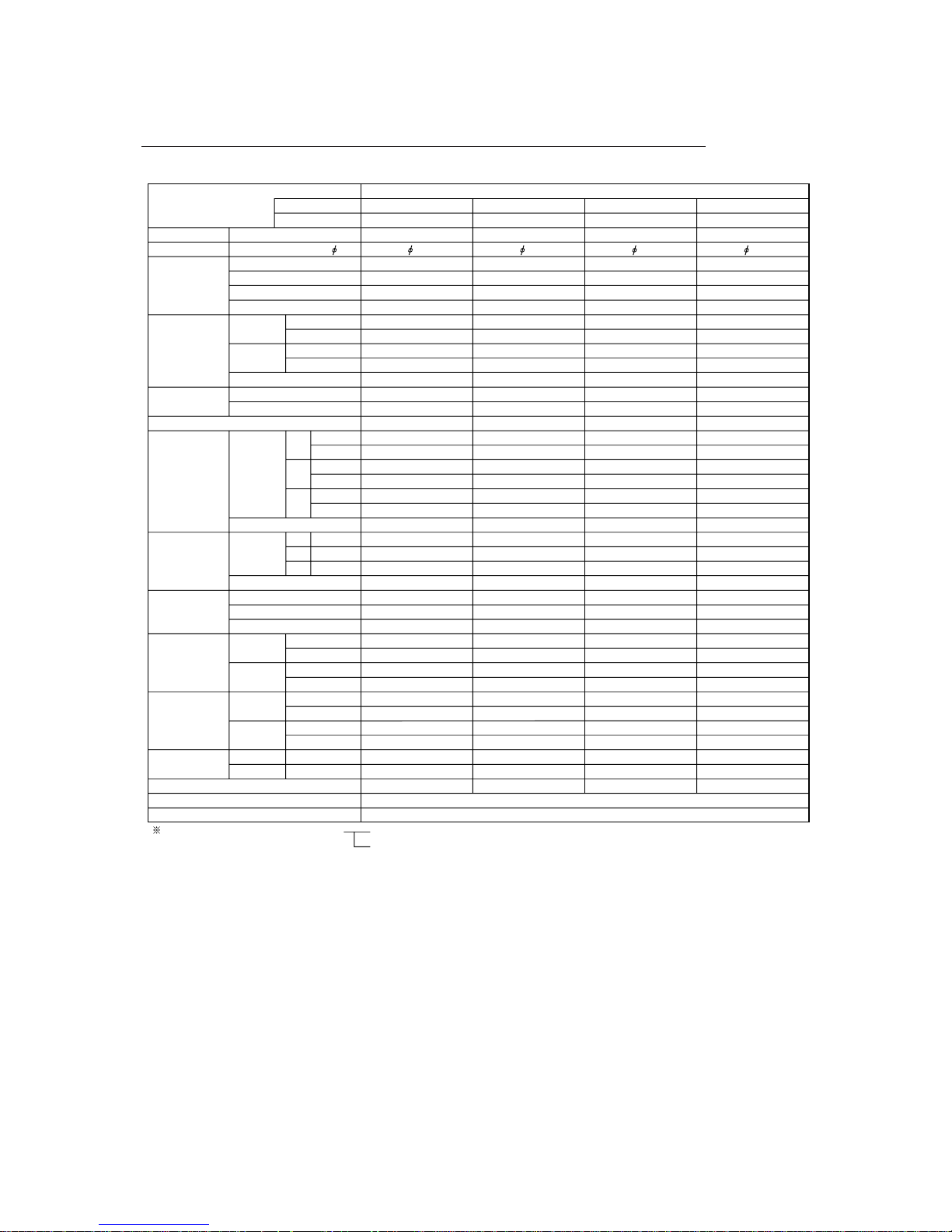
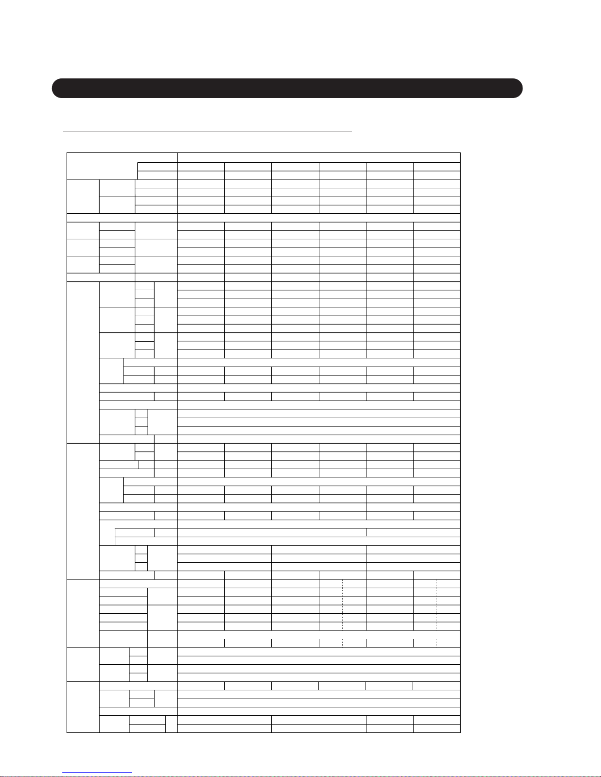
– 27 –
2.3
UNIVERSAL AB-SERIES (AB ✽ 14A, 14R, 18A, 18R, 24A, 24R)
2.3.1
AB ✽ 14A, 14R, 18A, 18R, 24A, 24R
MODEL
AB ✽ 14A
FLOOR / CEILING UNIVERSAL TYPE
Capacity
Power source 1 ~ 220-240V 50Hz
Total input
watts
Total
ampacity
EER
Starting current A 33
790 - 850
700 - 760
620 - 670
580 - 640
500 - 560
430 - 480
40.0 - 41.0
37.0 - 38.0
34.0 - 35.0
950 - 1,030
820 - 890
700 - 770
720 - 800
610 - 680
500 - 560
46.0 - 47.0
41.5 - 42.5
37.0 - 38.0
1,120 - 1,180
980 - 1,040
840 - 900
830 - 900
710 - 780
590 - 660
48.0 - 49.0
44.0 - 45.0
40.0 - 41.0
50 61
Cooling
Heating
Cooling
Heating
A
Cooling
Heating
kW/kW
Cooling
Heating
kW
BTU/h
kW
kW
BTU/h
4.00 - 4.10
13,700 - 14,000
—
—
1.67 - 1.80
—
7.9 - 8.3
—
2.39 - 2.28
—
AB ✽ 14R
3.95 - 4.05
13,500 - 13,800
4.90 - 5.00
16,700 - 17,100
1.62 - 1.76
1.61 - 1.73
7.6 - 8.0
7.6 - 8.0
2.44 - 2.30
3.04 - 2.89
AB ✽ 18A
5.30- 5.40
18,100 - 18,400
—
—
2.15 - 2.20
—
9.9 - 9.4
—
2.47 - 2.45
—
AB ✽ 18R
5.20 - 5.30
17,800 - 18,100
5.50 - 5.60
18,800 - 19,100
2.15 - 2.20
2.00 - 2.10
9.9 - 9.4
9.2 - 8.9
2.42 - 2.41
2.75 - 2.67
AB ✽ 24A
6.55 - 6.65
22,400 - 22,700
—
—
2.58 - 2.68
—
12.2 - 12.7
—
2.54 - 2.48
—
AB ✽ 24R
AO ✽ 14A AO ✽ 14R AO ✽ 18AZ AO ✽ 18RZ AB ✽ 24AB AB ✽ 24RZ
6.50 - 6.60
22,200 - 22,500
7.60 - 7.70
25,900 - 26,300
2.60 - 2.70
2.49 - 2.59
12.5 - 13.0
12.0- 12.5
2.50 - 2.44
3.05 - 2.97
Indoor
unit
Fan speed
Hi
Med
Low
r.p.m.
Air
circulation
Hi
Med
Low
m
3
/h
Noise level
(Sound
pressure)
Heat exchanger
Hi
Med
Low
dB(A)
kg
r.p.m.
dB(A)
kW
mm
Fan type x Q’ty
Fan motor output
Operation control
Weight Net/Gross
D
Outdoor
unit
Fan speed
Hi
Low
Air circulation
Noise level
m
3
/h
Fan motor output
kW
Compressor type
kW
kg
250
Motor output
Protection
Dimensions
Weight Net/Gross
Refrigerant
circuit
37 / 39 38 / 40 66 / 74 68 / 76 67 / 75 68 / 76
Cooling Cooling Heating Cooling Cooling Heating Cooling Cooling Heating
19.5 19.5 19.8
Suction pressure
Discharge
pressure
kg/cm
2
Discharge temp.
˚C
Suction temp.
Refr. pipe length m
˚C
5.1 5.1 4.3
92 89 95
10
19.0
4.9
92
7
20.0
4.8
91
410 1
19.0 20.0
4.9 4.2
97 84
81
20.1 20.7
4.9 4.0
98 87
61
5
13
1.000
6.35
12.7
13 45 12 12 42 11 12 45
Disch. air temp.
Condition
Indoor
air temp.
Cool
Heat
Cool
Ourdoor
air temp.
Heat
DB/WB
DB/WB
27.0˚C / 19.0˚C
20.0˚C /(15.0)˚C
35.0˚C / 24.0˚C
7.0˚C / 6.0˚C
Piping
10
5
20
8
Flare
20
8
Pipe size
(O.D.)
Liquid
Gas
Connection method
Height difference
Pipe length
Refrigerant charge kg
m
mm
H
Dimensions
W
Plate fin coil
Sirocco fan x 2
0.0300.016
Remote control
199
990
655
28 / 3728 / 37
735
2,590
56.0
750
—
1,600
49.0
0.022
Hermetic (rotary)
1,400
Internal protector (OCR)
530
750
0.060
Hermetic (recipro)
1,500
Internal protector (OCR), High pressure relief valve
643
840
336
0.060
1,875
643
840
336
735
280— 280—
2,590
56.0
30 / 39
0.040
Plate fin coil
Propeller x 1
mm
D
H
W
Hi
Heat exchanger
Fan type x Q’ty
Fan motor output
1.050
6.35
12.7
1.140
9.35
15.88
1.690
9.53
15.88
1.950
9.53
15.88
2.070
9.53
15.88
Outdoor unit
Indoor unit
Page 29
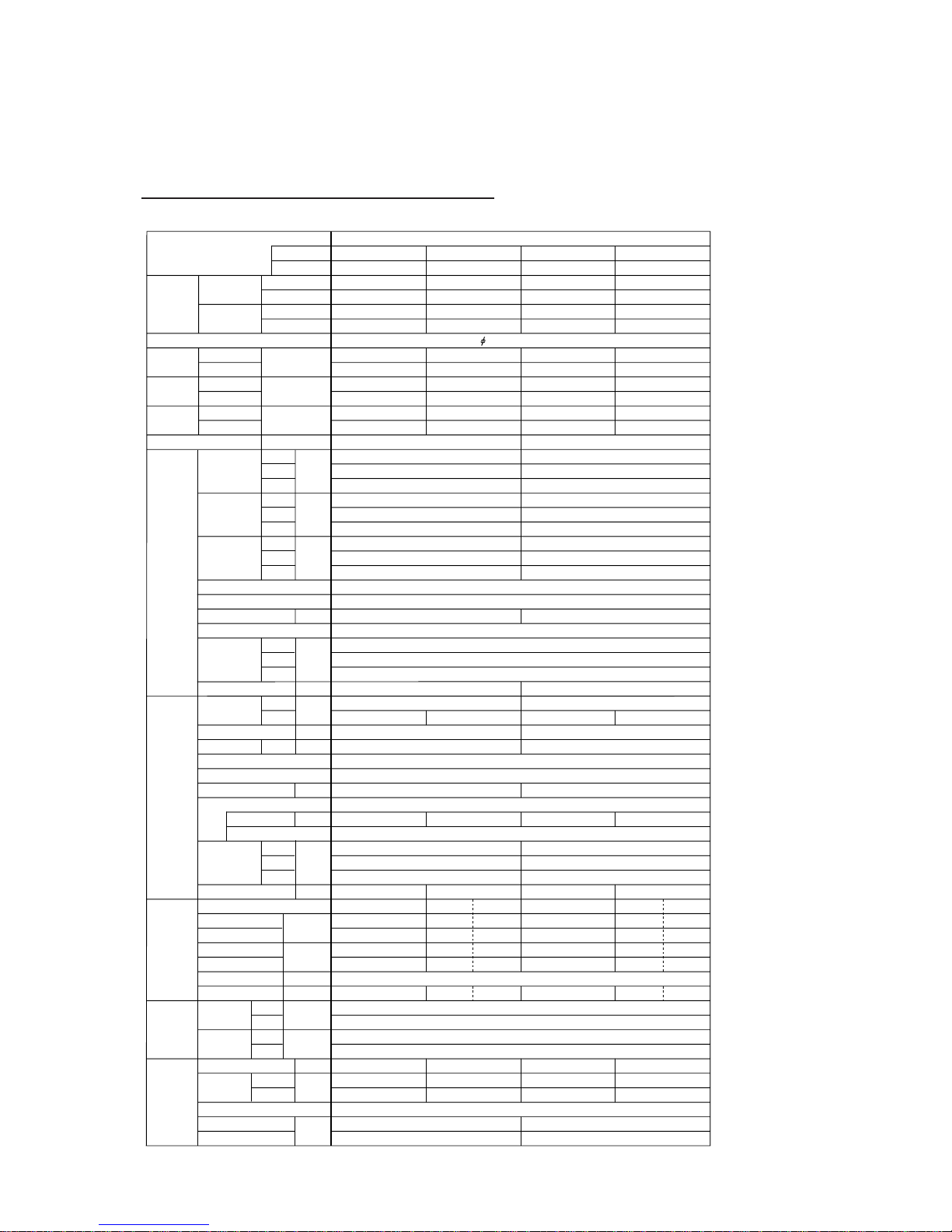
– 28 –
2.3.2 AB ✽ 18A, 18R, 24A, 24R
MODEL
FLOOR / CEILING UNIVERSAL TYPE
Capacity
Power source 1 50Hz / 220-240V
Total input
watts
Total
ampacity
EER
Starting current A
950 - 1,030
820 - 890
700 - 770
720 - 800
610 - 680
500 - 560
46.0 - 47.0
41.5 - 42.5
37.0 - 38.0
1,120 - 1,180
980 - 1,040
840 - 900
830 - 900
710 - 780
590 - 660
48.0 - 49.0
44.0 - 45.0
40.0 - 41.0
50 56
Cooling
Heating
Cooling
Heating
A
Cooling
Heating
kW/kW
Cooling
Heating
kW
BTU/h
kW
kW
BTU/h
AB ✽ 18A
5.3 - 5.4
18,100 - 18,400
—
—
2.05 - 2.15
—
10.2 - 10.4
—
2.59 - 2.51
—
AB ✽ 18R
5.2 - 5.3
17,700 - 18,100
5.7 - 5.8
19,500 - 19,800
2.05 - 2.15
1.90 - 2.00
9.5 - 9.5
9.0 - 9.1
2.54 - 2.47
3.60 - 2.90
AB ✽ 24A
6.55 - 6.75
22,400 - 23,000
—
—
2.67 - 2.78
—
13.2 - 13.4
—
2.45 - 2.42
—
AB ✽ 24R
AO ✽ 18AN AO ✽ 18RM AB ✽ 24AN AB ✽ 24RM
6.7 - 6.8
22,900 - 23,200
7.6 - 7.7
25,900 - 26,300
2.55 - 2.65
2.44 - 2.54
11.6 - 11.1
11.2- 10.6
2.63 - 2.57
3.11 - 3.03
Indoor
unit
Fan speed
Hi
Med
Low
r.p.m.
Air
circulation
Hi
Med
Low
m
3
/h
Noise level
(Sound
pressure)
Heat exchanger
Hi
Med
Low
dB(A)
kg
r.p.m.
dB(A)
kW
mm
Fan type x Q’ty
Fan motor output
Operation control
Weight Net/Gross
D
Outdoor
unit
Fan speed
Hi
Low
Air circulation
Noise level
m
3
/h
Fan motor output
kW
Compressor type
kW
kg
Motor output
Protection
Dimensions
Weight Net/Gross
Refrigerant
circuit
59 / 67 68 / 76 60 / 68 69 / 77
Cooling Cooling Heating Cooling Cooling Heating
Suction pressure
Operation model
Discharge pressure
kg/cm
2
Discharge temp.
˚C
Suction temp.
Refr. pipe length m
˚C
21
4.5
81
3.5 -3
21.5
4.8
90
5.5 8 -2
21 20
4.9 3.5
93 86
6.9
21 19
4.7 3.8
94 70
5
11.5 12 43.5 12 12 44
Disch. air temp.
Condition
Indoor
air temp.
Cool
Heat
Cool
Ourdoor
air temp.
Heat
DB/WB
DB/WB
27.0˚C / 19.0˚C
20.0˚C /(15.0)˚C
35.0˚C / 24.0˚C
7.0˚C / 6.0˚C
Piping
20
8
Flare
20
8
Pipe size
(O.D.)
Liquid
Gas
Connection method
Height difference
Pipe length
Refrigerant charge kg
m
mm
H
Dimensions
W
Plate fin coil
Sirocco fan x 2
0.030
Remote control
199
990
655
28 / 37
735
2,590
56.0
0.060
Hermetic (Rotary)
1,665 1,500
Internal protector (OCR)
643
840
336
0.060
2,0002,200
643
840
336
735
280— 280—
2,590
56.0
30 / 39
0.040
Plate fin coil
Propeller x 1
mm
D
H
W
Hi
Heat exchanger
Fan type x Q’ty
Fan motor output
1.5
9.53
15.88
1.95
9.53
15.88
1.87
9.53
15.88
2.070
9.53
15.88
Outdoor unit
Indoor unit
(Nontropicalized models)
Page 30
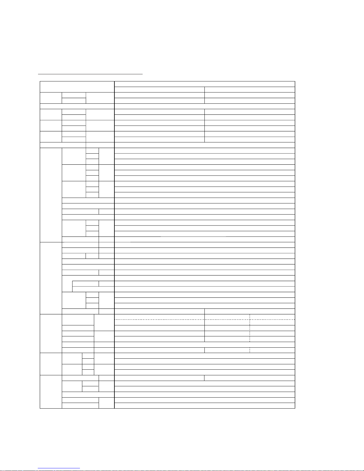
– 29 –
2.3.3
ABB24A, ABB24R
MODEL
ABB24A
FLOOR / CEILING UNIVERSAL TYPE
Capacity
Power source
1 ~ 220V 60Hz
Total input
watts
Total
ampacity
EER
Starting current A
66
1,150
990
870
900
780
660
49.0
45.0
41.0
Cooling
Heating
W
Cooling
Heating
A
Cooling
Heating
W/W
Cooling
Heating
W
5,300
—
3,100
14.6
—
—
1.71
—
ABB24R
5,300
7,100
3,100
14.6
2,650
12.5
1.71
2.68
Indoor
unit
Fan speedHiMed
Low
r.p.m.
Air
circulation
Hi
Med
Low
m
3
/h
Noise level
(Sound
pressure)
Heat exchanger
Hi
Med
Low
dB(A)
kg
r.p.m.
dB(A)
kW
mm
Fan type x Q’ty
Fan motor output
Operation control
Weight Net/Gross
D
Outdoor
unit
Fan speed
Air circulation
Noise level
m
3
/h
Fan motor output
kW
Compressor type
kW
kg
Motor output
Protection
Dimensions
Weight Net/Gross
Refrigerant
circuit
67 / 75 68 / 76
Cooling
Suct. pressure
Disch.
pressure
kg/cm
2
Discharge temp.
˚C
Suction temp.
Refr. pipe length m
˚C
24.5
4.9
91
8
13
1.750 2.070
Cooling
24.9
4.9
102
7
13
5
Disch. air temp.
Condition
Indoor
air temp.
Cool
Heat
Cool
Ourdoor
air temp.
Heat
DB/WB
DB/WB
29.0˚C / 19.0˚C
21.0˚C /(15.5)˚C
46.0˚C / 24.0˚C
7.0˚C / 6.0˚C
9.53
15.88
Flare
15
20
Piping
Pipe size
(O.D.)
Liquid
Gas
Connection method
Height difference
Pipe length
Refrigerant charge kg
m
mm
H
Dimensions
W
Plate fin coil
Sirocco fan x 2
0.040
Remote control
199
990
655
30 / 39
735
2,590
56.0
0.060
Hermetic (Recipro)
1,900
Internal protector (OCR), High pressure relief valve
643
840
336
Plate fin coil
Propeller x 1
mm
D
H
W
Hi
Heat exchanger
Fan type x Q’ty
Fan motor output
Heating
19.7
4.0
77
1
45
Page 31

3. OUTLINE AND DIMENSIONS
– 30 –
3.1 MODELS : AS ✽ 7A, 7R
3.1.1 INDOOR UNIT
3.1.2 OUTDOOR UNIT
790 (31-3/32")
808 (31-13/16")
170 (6-11/16")
150 (5-29/32")
248 (9-25/32")
650 (25-19/32")
250 (9-27/32")
535 (21-1/16")
Unit : mm (inch)
Page 32

– 31 –
3.2 MODELS : AS ✽ 9A, 9R, 12A , 12R
3.2.1
INDOOR UNIT
3.2.2
OUTDOOR UNIT
815 (32-3/32")
175 (6-57/64")
176 (6-15/16")
260 (10-1/4")
500 (19-11/16")
250 (9-27/32")
695 (27-3/8")
290 (11-13/32")
265 (10-7/16")
535 (21-1/16")
13 (1/2")
98 (3-27/32")
Unit : mm (inch)
Page 33

– 32 –
3.3 MODELS : AS ✽ 14A, 14R
3.3.1 INDOOR UNIT
3.3.2
OUTDOOR UNIT
900 (35 - 7/16")
172 (6 - 49/64")
285 (11 - 7/32")
750 (29 - 17/32")
250 (9 - 27/32")
285 (11 - 7/32")
13 (1/2")
530 (20 - 55/64")
540 (21 - 17/64")
Unit : mm (inch)
Page 34

– 33 –
3.4 MODELS : AS ✽ 17A, 17R
3.4.1
INDOOR UNIT
3.4.2
OUTDOOR UNIT
900 (35 - 7/16")
172 (6 - 49/64")
285 (11 - 7/32")
25 (1" )
840 ( 33-1/16" )
804 (31-21/32" )
336 (13-1/4" )
643 ( 25-5/16" )
333 (13-7/64" )
Unit : mm (inch)
Page 35

– 34 –
3.5 MODELS :
AS ✽ 20A, 20R, 24A, 24R, 30A, 30R, ASC-502B, ASC-602B
3.5.1
INDOOR UNIT
660 (25-31/32")
5 (3/16" )
720 (28-11/32")
1,250 (49-7/32" )
320 (12-19/32" )
660 (25-31/32")
720 (28-11/32")
195
(7-11/16" )
57
(2-1/4")
57 (2-1/4")
244 (9-19/32")
55
(2-5/32")
55
(2-5/32")
315 (12-13/32")
241 (9-1/2")
186 (7-11/32")
131 (5-5/32")
76(3")
36 (1-13/32")
24 (15/16")
Wall hook bracket
84 (3-5/16") - ø6 (1/4") holes
for tapping screw
20 (25/32") - ø12 (15-32") x 18holes
for bolt
Piping
inlet
Piping inlet
622 (24-1/2")
598 (23-17/32")
466 (18-11/32") 472(18-19/32")
241(9-1/2")
366
(14-13/32")
133
(5-1/4")
373
(14-11/16")
604
(23-25/32")
216
(8-1/2")
219
(8-5/8")
628 (24-23/32")
320(12-19/32")
Connecting
pipe
15.88 (5/8")
9. 5 2 (3/8")
Gas
Liquid
16 (5/8")
Drain pipe
Unit : mm (inch)
Page 36

– 35 –
3.5.2 OUTDOOR UNIT
25 (1" )
840 ( 33-1/16" )
804 (31-21/32" )
336 (13-1/4" )
643 ( 25-5/16" )
333 (13-7/64" )
Models : AO ✽ 20A, 20R, 24A , 24R, AOC-502B, AOC-602B
350
(13-25/32"
)
333
(13-7/64"
)
804
(31-21/32"
)
900 (35-7/16")
900 (35-7/16")
930 (36-39/64")
19 (3/4"
)
Models : AO ✽ 30A, 30R
Unit : mm (inch)
Page 37

– 36 –
3.6 MODELS : AS ✽ 14A, 14R, 18A, 18R, 24A, 24R
3.6.1
INDOOR UNIT
[Rear View]
990 (38-31/32")
199 (7-27/32")
200 (7-7/8")
175 (6-15/16")
500 (19-11/16")
530 (20-7/8")
900 (35-7/16")
655 (25-25/32")
Unit : mm (inch)
Page 38

– 37 –
3.6.2 OUTDOOR UNIT
25 (1" )
840 ( 33-1/16" )
804 (31-21/32" )
336 (13-1/4" )
643 ( 25-5/16" )
333 (13-7/64" )
Models : AO ✽ 18A, 18R, 24A , 24R
13 (1/2")
750 (29-17/32")
517 (20-23/64")
493 (19-13/32")
540 (21-1/4")
( Mounting bolt pitch )
250 (9-27/32")
285 (11-7/32")
Models : AO ✽ 14A, 14R
Unit : mm (inch)
Page 39

– 38 –
4. DATA
4.1 PERFORMANCE CUR VE
4.1.1
MODEL : COMPACT SII, MII & LI (AS✽14A, AS✽14R) SERIES
130
120
110
100
90
80
70
130
120
110
100
90
80
70
60
2021 25 30 35 40 4546 50
31/22
29/21.5
27/19
25/17.5
23/16
21/14.5
19/12.5
Indoor
DB/WB (˚C)
Indoor
DB/WB (˚C)
Outdoor DB(˚C)
Capacity (%)
31/22
29/21.5
27/19
25/17.5
23/16
21/14.5
19/12.5
Input (%)
Cooling
130
120
110
100
90
80
70
130
120
110
100
90
80
70
60
-5 0/-2 5/3 10/7.5 15/12
20 21/17.5
25 30 35
Indoor
DB(˚C)
Outdoor DB/WB(˚C)
Capacity (%)
15
20
25
25
20
15
Input (%)
Heating
Page 40

– 39 –
4.1.2 AS ✽ 17A, 20A, 24A (50Hz models)
4.1.3 AS ✽ 30A (50Hz models)
130
120
110
100
90
80
70
130
120
110
100
90
80
70
60
15 20 25 30 35 40 45 50 55
29/21˚C
29/19
27/19
25/19
23/19
23/17
29/21˚C
29/19
27/19
25/19
23/19
23/17
Indoor
DB/WB
Outdoor DB (˚C)
Input (%) Capacity (%)
Tropicalized models
Nontropicalized models
Cooling
130
120
110
100
90
80
70
130
120
110
100
90
80
70
60
0 5 10 15 20 25 30 35 40 45 50 55
Indoor
DB/WB
29/21˚C
29/19
27/19
25/19
23/19
23/17
29/21˚C
29/19
27/19
25/19
23/19
23/17
29/19
27/19
25/19
23/19
23/17
29/21
29/21
29/19
27/19
25/19
23/19
23/17
Outdoor DB (˚C)
Input (%) Capacity (%)
140
Cooling
Page 41

– 40 –
4.1.4 AS ✽ 17R, 20R, 24R (50Hz models)
130
120
110
100
90
80
70
130
120
110
100
90
80
70
60
0 5 10 15 20 25 30 35 40 45 50 55
Indoor
DB/WB
29/21˚C
29/19
27/19
25/19
23/19
23/17
29/21˚C
29/19
27/19
25/19
23/19
23/17
29/19
27/19
25/19
23/19
23/17
29/21
29/21
29/19
27/19
25/19
23/19
23/17
Input (%) Capacity (%)
140
Tropicalized models
Nontropicalized modelsLower limit of AS
✽
17R
Cooling
130
120
110
100
90
80
70
130
120
110
100
90
80
70
60
0-5 5 10 15 20 25
15˚C
20˚C
25˚C
25˚C
20˚C
15˚C
Indoor
DB
Outdoor DB (°C) RH=85%
Input (%) Capacity (%)
Heating
Page 42

– 41 –
4.1.5 ASB20R, ASB24R, ASB30R (60Hz models)
150
140
130
120
110
100
90
130
120
110
100
90
80
70
60
15 20 25 30 35 40 45 50 55
29/21˚C
29/19
27/19
25/19
23/19
23/17
29/21˚C
29/19
27/19
25/19
23/19
23/17
Indoor
DB/WB
Outdoor DB (˚C)
Input (%) Capacity (%)
Cooling
130
120
110
100
90
80
70
130
120
110
100
90
80
70
60
0-5 5 10 15 20 25
15˚C
20˚C
25˚C
25˚C
20˚C
15˚C
Indoor
DB
Outdoor DB (˚C) RH=85%
Input (%) Capacity (%)
Heating
Page 43

– 42 –
4.1.6 ASB20A, ASB24A, ASB30A (60Hz models)
4.1.7 ASC-502B, ASC-602B (60Hz models)
150
140
130
120
110
100
90
130
120
110
100
90
80
70
60
15 20 25 30 35 40 45 50 55
29/21˚C
29/19
27/19
25/19
23/19
23/17
29/21˚C
29/19
27/19
25/19
23/19
23/17
Indoor
DB/WB
Outdoor DB (˚C)
Input (%) Capacity (%)
Cooling
130
120
110
100
90
80
70
130
120
110
100
90
80
70
60
15 20 25 30 35 40 45 50 55
29/21˚C
27/19.5
27/19
25/19
23/19
23/17
29/21˚C
27/19.5
27/19
25/19
23/19
23/17
Indoor
DB/WB
Outdoor DB (˚C)
Input (%) Capacity (%)
Cooling
Page 44

– 43 –
4.1.8 AB ✽ 14R (50Hz models)
130
120
110
100
90
80
70
130
120
110
100
90
80
70
60
15 20 25 30 35 40 45 50 55
29/21˚C
27/19.5
27/19
25/19
23/19
23/17
29/21˚C
27/19.5
27/19
25/19
23/19
23/17
Indoor
DB/WB
Outdoor DB (˚C)
Input (%) Capacity (%)
Cooling
130
120
110
100
90
80
70
130
120
110
100
90
80
70
60
0-5 5 10 15 20 25
15˚C
20˚C
25˚C
25˚C
20˚C
15˚C
Indoor
DB
Outdoor DB (˚C) RH=85%
Input (%) Capacity (%)
Heating
Page 45

– 44 –
4.1.9 AB ✽ 18R, AB ✽ 24R (50Hz models)
130
120
110
100
90
80
70
130
120
110
100
90
80
70
60
0 5 10 15 20 25 30 35 40 45 50 55
Indoor
DB/WB
29/21˚C
29/19
27/19
25/19
23/19
23/17
29/21˚C
29/19
27/19
25/19
23/19
23/17
29/19
27/19
25/19
23/19
23/17
29/21
29/21
29/19
27/19
25/19
23/19
23/17
Outdoor DB (˚C)
Input (%) Capacity (%)
140
Tropicalized models
Nontropicalized models
Cooling
130
120
110
100
90
80
70
130
120
110
100
90
80
70
60
0-5 5 10 15 20 25
15˚C
20˚C
25˚C
25˚C
20˚C
15˚C
Indoor
DB
Outdoor DB (˚C) RH=85%
Input (%) Capacity (%)
Heating
Page 46

– 45 –
4.1.10 AB ✽ 18A, AB ✽ 24A (50Hz models)
4.1.11 AB ✽ 14A (50Hz models)
130
120
110
100
90
80
70
130
120
110
100
90
80
70
60
15 20 25 30 35 40 45 50 55
29/21˚C
29/19
27/19
25/19
23/19
23/17
29/21˚C
29/19
27/19
25/19
23/19
23/17
Indoor
DB/WB
Outdoor DB (˚C)
Input (%) Capacity (%)
Tropicalized models
Nontropicalized models
Cooling
130
120
110
100
90
80
70
130
120
110
100
90
80
70
60
15 20 25 30 35 40 45 50 55
29/21˚C
27/19.5
27/19
25/19
23/19
23/17
29/21˚C
27/19.5
27/19
25/19
23/19
23/17
Indoor
DB/WB
Outdoor DB (˚C)
Input (%) Capacity (%)
Cooling
Page 47

– 46 –
4.1.12 ABB24A (60Hz models)
150
140
130
120
110
100
90
130
120
110
100
90
80
70
60
15 20 25 30 35 40 45 50 55
29/21˚C
29/19
27/19
25/19
23/19
23/17
29/21˚C
29/19
27/19
25/19
23/19
23/17
Indoor
DB/WB
Outdoor DB (˚C)
Input (%) Capacity (%)
Cooling
Page 48

– 47 –
4.1.13 ABB24R (60Hz models)
150
140
130
120
110
100
90
130
120
110
100
90
80
70
60
15 20 25 30 35 40 45 50 55
29/21˚C
29/19
27/19
25/19
23/19
23/17
29/21˚C
29/19
27/19
25/19
23/19
23/17
Indoor
DB/WB
Outdoor DB (˚C)
Input (%) Capacity (%)
Cooling
130
120
110
100
90
80
70
130
120
110
100
90
80
70
60
0-5 5 10 15 20 25
15˚C
20˚C
25˚C
25˚C
20˚C
15˚C
Indoor
DB
Outdoor DB (˚C) RH=85%
Input (%) Capacity (%)
Heating
Page 49

– 48 –
MODELS
TEMPERATURE RANGE
INDOOR UNIT OUTDOOR UNIT
COOL
DRY
COOL
HEAT
COOL
COOL
COOL
HEAT
COOL
DRY
COOL
DRY
COOL
DRY
COOL
DRY
HEAT
COOL
DRY
HEAT
COOL
DRY
COOL
DRY
COOL
DRY
HEAT
COOL
DRY
HEAT
Approx. 18°C to 32°C Approx. 18°C to 43°C
Approx. 18°C to 32°C Approx. 18°C to 43°C
Approx. 16°C to 30°C Approx. -5°C to 21°C
Approx. 18°C to 32°C Approx. 18°C to 46°C
Approx. 18°C to 32°C Approx. 18°C to 52°C Tropicalized model
Approx. 18°C to 46°C Nontropicalized model
Approx. 18°C to 32°C Approx. 18°C to 46°C
Approx. 16°C to 30°C Approx. 0°C to 21°C
Approx. 18°C to 32°C Approx. 18°C to 52°C Tropicalized model
Approx. 10°C to 46°C Nontropicalized model
Approx. 18°C to 32°C Approx. 18°C to 43°C
Approx. 18°C to 32°C Approx. 0°C to 52°C
Approx. 18°C to 32°C Approx. 0°C to 52°C Tropicalized model
Approx. 0°C to 46°C Nontropicalized model
Approx. 30°C or less Approx. 0°C to 21°C
Approx. 18°C to 32°C Approx. 0°C to 52°C
Approx. 30°C or less Approx. 0°C to 21°C
Approx. 18°C to 32°C Approx. 21°C to 43°C
Approx. 18°C to 32°C Approx. 21°C to 52°C Tropicalized model
Approx. 0°C to 46°C Nontropicalized model
Approx. 18°C to 32°C Approx. 21°C to 43°C
Approx. 16°C to 30°C Approx. 0°C to 21°C
Approx. 18°C to 32°C Approx. 0°C to 52°C Tropicalized model
Approx. 0°C to 46°C Nontropicalized model
Approx. 16°C to 30°C Approx. 0°C to 21°C
Note: Outdoor Unit Standard model – – – – – – – – – – – – – – – – – 21 to 43°C (Cooling)
0 to 21°C (Heating)
Tropicalized model – – – – – – – – – – – – – – – 21 to 52°C (Cooling)
Nontropicalized model – – – – – – – – – – – – – – 21 to 46°C (Cooling)
Tropicalized model with
low ambient cooling operation – – – – – – – – – – 0 to 52°C (Cooling)
AS ∗7A
AS
∗
9A
AS
∗
12A
AS
∗
7R
AS
∗
9R
AS
∗
12A
AS ∗14A
AS ∗17A
AS
∗
14R
AS
∗
17R
AS
∗
20A
AS
∗
24A
except ASC-502B
and ASC-602B
ASC-502B
ASC-602B
ASG30A
ASY30A
AS
∗
20R
AS
∗
24R
AS
∗
30R
AB
∗
14A
AB
∗
18A
AB
∗
24A
AB
∗
14R
AB
∗
18R
AB
∗
24R
4.2 TEMPERATURE RANGE
Page 50

– 49 –
4.3 REFRIGERANT CHARGING
4.3.1 COMPACT SII & MII SERIES
Additional
refrigerant
g/m
AS
∗
7A, AS∗7R
AS
∗
9A, AS∗9R
AS
∗
12A, AS∗12R
16g80g32gNone
33ft (10m)
160g
49ft (15m)23ft (7m)16ft (5m)
Pipe length
Models
ADDITIONAL
REFRIGERANT
Note: When the piping is longer than 5m, additional charging is necessary.
ASY12ASG, ASM, AST12ASH, ASA12ASF
Additional
refrigerant
g/m
AS
∗
14A
AS
∗
14R
20g
Additional
refrigerant
g/m
15g225g150g75g30gNone
10g150g100g50g20gNone
100g40gNone
33ft (10m)23ft (7m)16ft (5m)
Pipe length
Models
ADDITIONAL
REFRIGERANT
ADDITIONAL
REFRIGERANT
LI SERIES
AS14A, 14R
AS17A, 17R
AS17A/AO17AB
AS17R/AO17RB
AS17A/AO17AN
AS17R/AO17RN
49ft (15m)33ft (10m)23ft (7m) 66ft (20m)16ft (5m)
Pipe length
Models
Page 51

4.3.2 W ALL MOUNTED LARGE AS-SERIES
– 50 –
Additional
refrigerant
g/m(oz/ft)
AS
∗
20A/
AO
∗
20AZ
AS
∗
20R/
AO
∗
20RZ
AS
∗
24A/
AO
∗
24AB
AS
∗
24R/
AO
∗
24RZ
1,320g
(46.6 oz)
1,380g
(48.7 oz)
1,440g
(50.8 oz)
1,500g
(52.9 oz)
12g
(0.13 oz)
ASS20A/
AOS20A
ASB20A/
AOB20R
ASB24A/
AOB24A
ASB24R/
AOB24R
AS
∗
30A/
AO
∗
30A
ASB30A/
AOB30A
AS
∗
30R/
AO
∗
30R
ASB30R/
AOB30R
AS
∗
20A/
AO
∗
20AN
AS
∗
24A/
AO
∗
24AN
AS
∗
20R/
AO
∗
20RM
AS
∗
24R/
AO
∗
24RM
1,350g
(47.6 oz)
1,410g
(49.7 oz)
1,470g
(51.9 oz)
1,530g
(53.9 oz)
12g
(0.13 oz)
ASC-502B/
AOC-502B
ASC-602B/
AOC-602B
1,870g
(66.0 oz)
1,930g
(68.1 oz)
1,990g
(70.2 oz)
2,050g
(72.3 oz)
12g
(0.13 oz)
1,900g
(67.0 oz)
2,150g
(75.8 oz)
2,400g
(84.7 oz)
2,650g
(93.5 oz)
50g
(0.53 oz)
1,690g
(59.6 oz)
1,930g
(68.1 oz)
2,170g
(70.5 oz)
2,410g
(85.0 oz)
48g
(0.51 oz)
2,000g
(70.5 oz)
2,060g
(72.7 oz)
2,120g
(74.8 oz)
2,180g
(76.9 oz)
12g
(0.13 oz)
1,750g
(61.7 oz)
1,810g
(63.8 oz)
1,870g
(66.0 oz)
1,930g
(68.1 oz)
12g
(0.13 oz)
2,020g
(71.3 oz)
2,080g
(73.4 oz)
2,140g
(75.5 oz)
2,200g
(77.6 oz)
12g
(0.13 oz)
2,070g
(73.0 oz)
2,320g
(81.8 oz)
2,570g
(90.7 oz)
2,820g
(99.5 oz)
50g
(0.53 oz)
2,070g
(73.0 oz)
2,240g
(79.0 oz)
2,140g
(85.0 oz)
2,580g
(91.0 oz)
34g
(0.36 oz)
2,300g
(81.1 oz)
2,385g
(84.1 oz)
2,470g
(87.1 oz)
2,555g
(90.1 oz)
2,640g
(93.1 oz)
2,725g
(96.1 oz)
17g
(0.18 oz)
2,300g
(81.1 oz)
2,385g
(84.1 oz)
2,470g
(87.1 oz)
2,555g
(90.1 oz)
2,640g
(93.1 oz)
2,725g
(96.1 oz)
17g
(0.18 oz)
2,400g
(84.7 oz)
2,650g
(93.5 oz)
2,900g
(102.3 oz)
3,150g
(111.1 oz)
3,400g
(119.9 oz)
50g
(0.53 oz)
50g
(0.53 oz)
2,450g
(86.5 oz)
2,700g
(95.3 oz)
2,950g
(104.1 oz)
3,200g
(112.9 oz)
3,450g
(121.7 oz)
FULL
CHARGE
AMOUNT
66ft (20m)49ft (15m)33ft (10m) 98ft (30m)82ft (25m)16ft (5m)
Pipe length
Models
1,500g
(52.9 oz)
1,580g
(55.7 oz)
1,666g
(58.6 oz)
1,740g
(61.4 oz)
16g
(0.17 oz)
1,950g
(68.8 oz)
2,100g
(74.1 oz)
2,250g
(79.4 oz)
2,400g
(84.7 oz)
30g
(0.32 oz)
1,870g
(66.0 oz)
1,950g
(68.8 oz)
2,030g
(71.6 oz)
2,110g
(74.4 oz)
16g
(0.17 oz)
2,120g
(74.8 oz)
2,270g
(80.1 oz)
2,420g
(85.4 oz)
2,570g
(90.7 oz)
30g
(0.32 oz)
Page 52

– 51 –
4.3.3 FLOOR / CEILING UNIVERSAL AB-SERIES
Additional
refrigerant
g/m (oz/ft)
AB
∗
14A/
AO
∗
14AN
AB∗14R/
AO
∗
14RN
AB
∗
18A/
AO
∗
18AZ
AB
∗
18R/
AO
∗
18RZ
AB
∗
24A/
AO
∗
24AB
(50Hz)
AB
∗
24R/
AO
∗
24RZ
(50Hz)
AB
∗
14A/
AO
∗
14AG
AB∗14R/
AO
∗
14RG
AB
∗
18A/
AO
∗
18AN
AB
∗
18R/
AO
∗
18RM
AB
∗
24A/
AO
∗
24AN
(50Hz)
AB
∗
24R/
AO
∗
24RM
(50Hz)
AB
∗
24A/
AO
∗
24AZ
(60Hz)
AB
∗
24R/
AO
∗
24RZ
(60Hz)
1,000g
(35.2 oz)
1,150g
(40.5 oz)
30g
(0.32 oz)
1,050g
(36.9 oz)
1,200g
(42.2 oz)
30g
(0.32 oz)
1,140g
(40.1 oz)
1,200g
(42.2 oz)
12g
(0.13 oz)
1,790g
(63.1 oz)
2,040g
(72.0 oz)
50g
(0.53 oz)
2,000g
(70.5 oz)
2,060g
(72.7 oz)
2,120g
(74.8 oz)
2,180g
(76.9 oz)
12g
(0.13 oz)
2,070g
(72.9 oz)
2,320g
(81.7 oz)
2,570g
(90.5 oz)
2,820g
(99.3 oz)
1,930g
(67.9 oz)
1,260g
(44.4 oz)
1,320g
(46.5 oz)
2,290g
(80.8 oz)
2,540g
(89.6 oz)
50g
(0.53 oz)
1,750g
(61.6 oz)
1,810g
(63.7 oz)
1,870g
(65.8 oz)
12g
(0.13 oz)
50g
(0.53 oz)
2,070g
(72.9 oz)
2,320g
(81.7 oz)
2,570g
(90.5 oz)
2,820g
(99.3 oz)
FULL
CHARGE
AMOUNT
33ft (10m) 66ft (20m)49ft (15m)16ft (5m)
Pipe length
Models
1,090g
(38.4 oz)
1,240g
(43.7 oz)
30g
(0.32 oz)
1,100g
(38.8 oz)
1,250g
(44.1 oz)
30g
(0.32 oz)
1,500g
(52.9 oz)
1,580g
(55.7 oz)
16g
(0.17 oz)
1,950g
(68.8 oz)
2,160g
(76.2 oz)
42g
(0.49 oz)
1,870g
(66.0 oz)
1,950g
(68.8 oz)
2,030g
(71.6 oz)
2,110g
(74.4 oz)
16g
(0.17 oz)
2,320g
(81.8 oz)
2,470g
(87.1 oz)
2,620g
(92.4 oz)
2,770g
(97.7 oz)
1,660g
(58.6 oz)
1,740g
(61.4 oz)
2,370g
(83.5 oz)
2,580g
(91.0 oz)
30g
(0.32 oz)
Page 53
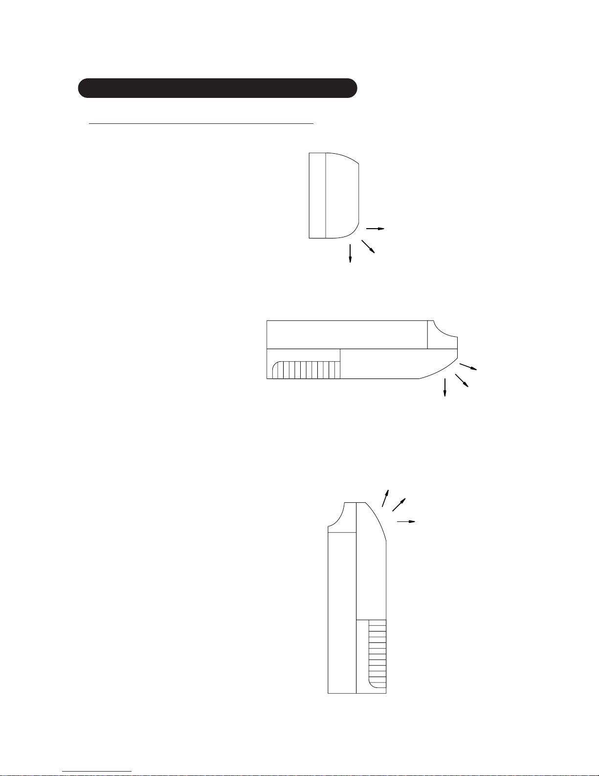
– 52 –
4.4 AIR VELOCITY DISTRIBUTION
4.4.1 AIR DISCHARGE ANGLE
Horizontal
Center
Center
Center
Upward
Upward
Downward
Forward
Vertical
● AS : WALL MOUNTED
● AB : UNDER CEILING
● AB : FLOOR CONSOLE
Page 54
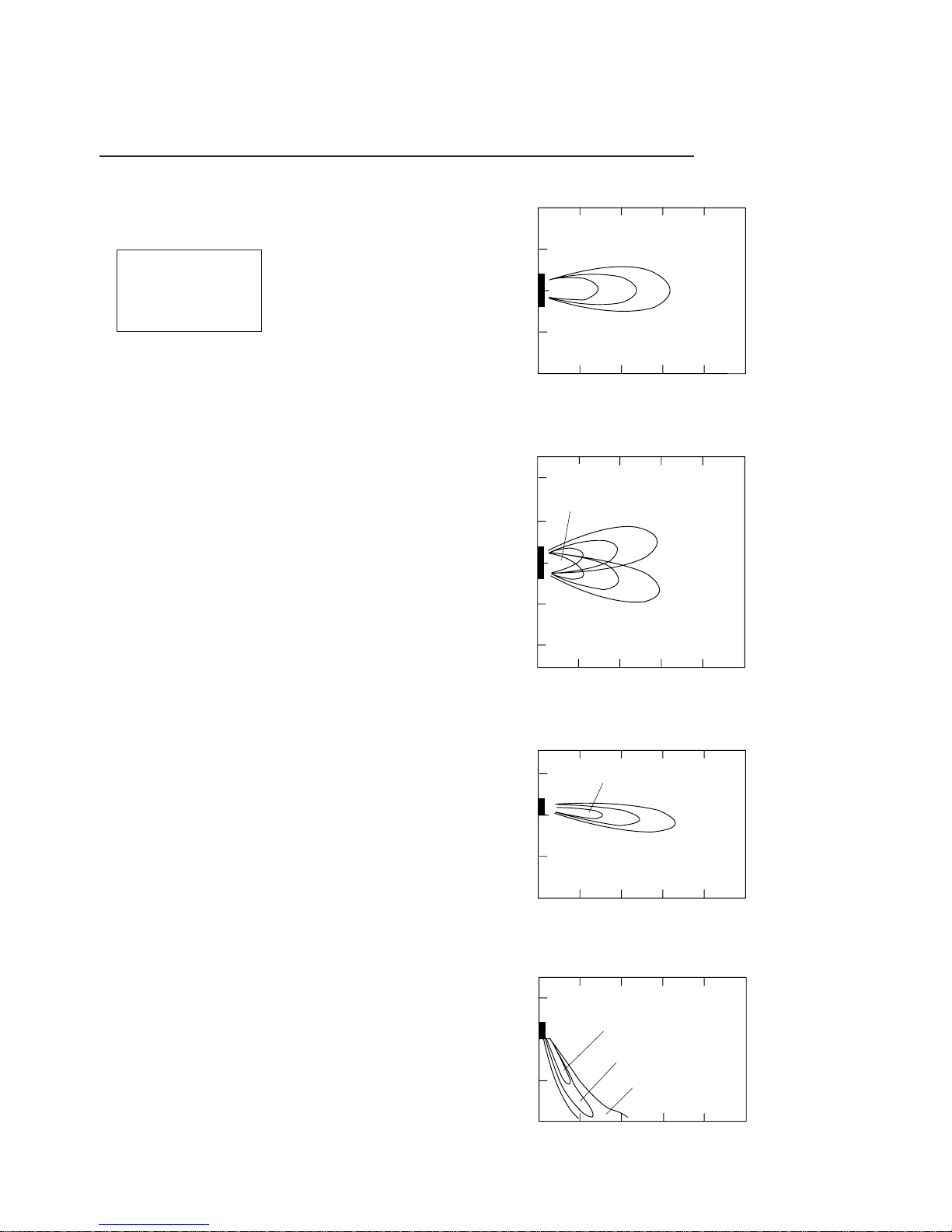
– 53 –
4.4.2 COMPACT SII SERIES MODELS : AS ✽ 7A, 7R
2.0 1.0 0.5
2.0
1.0
0.5
2.0
1.0
0.5
1.0
0.5
2
1
0
1
2
01 234
2
1
0
1
2
0
1234
3
2
1
01 234
0
1
2
01 234
2.0
1.0
0.5
Unit: m/s
Louver:Right
Louver:Left
Unit: m/s
Unit: m/s
Unit: m/s
(m)
(m)
(m)
(m)
(m)
(m)
(m)
(m)
Fig. 3.4.2-1
TOP VIEW
FLOW CONTROL PANEL : Horiz.
LOUVER : Center
Fig. 3.4.2-2
TOP VIEW
FLOW CONTROL PANEL : Horiz.
LOUVER : Right & Left
Fig. 3.4.2-3
SIDE VIEW
FLOW CONTROL PANEL : Horiz.
LOUVER : Center
Fig. 3.4.2-4
SIDE VIEW
FLOW CONTROL PANEL : Vert .
LOUVER : Center
Note :
Fan speed : Hi
Operation : FAN
Voltage : 240V
Page 55

– 54 –
4.4.3 LI SERIES MODELS :
AS ✽ 9A, 9R, 12A, 12R, AS ✽ 14A, 14R, 17A, 17R
2.0 1.0 0.5
2.0
1.0
0.5
2.0
2.0
1.0
0.5
1.0
0.5
2
1
0
1
2
01 234
2
1
0
1
2
01 234
Unit: m/s
Louver:Right
Louver:Left
Unit: m/s
Unit: m/s
3
2
1
01 234
3
2
1
01 234
Unit: m/s
2.0
1.0
0.5
(m)
(m)
(m)
(m)
(m)
(m)
(m)
(m)
Fig. 3.4.3-1
TOP VIEW
FLOW CONTROL PANEL : Horiz.
LOUVER : Center
Fig. 3.4.3-2
TOP VIEW
FLOW CONTROL PANEL : Horiz.
LOUVER : Right & Left
Fig. 3.4.3-3
TOP VIEW
FLOW CONTROL PANEL : Horiz.
LOUVER : Center
Fig. 3.4.3-4
TOP VIEW
FLOW CONTROL PANEL : Vert.
LOUVER : Center
Note :
Fan speed : Hi
Operation : FAN
Voltage : 240V
Page 56

– 55 –
4.4.4 AIR VELOCITY DISTRIBUTION
MODELS : AS ✽ 20A, AS ✽ 20R, ASC-502B (50, 60Hz models)
2.0
1.0
0.5 0.25
2.0
1.0
0.5
0.25
2.0
1.0
0.5
0.5
0.25
0.25
1.0
2
1
0
1
2
0123456 789
Unit: m/s
0123456789
3
2
1
012 3456 789
Unit: m/s
2.0
0.25
0.5
3
2
1
0123456
Unit: m/s
3
2
1
0
1
2
3
Unit: m/s
1.0
(m)
(m)
(m)
(m)
(m)
(m)
(m)
(m)
Fig. 4.4.4-1
TOP VIEW
FLOW CONTROL PANEL : Horiz.
LOUVER : Center
Fig. 4.4.4-2
TOP VIEW
FLOW CONTROL PANEL : Horiz.
LOUVER : Right & Left
Fig. 4.4.4-3
SIDE VIEW
FLONT CONTROL PANEL : Horiz.
LOUVER : Center
Fig. 4.4.4-4
SIDE VIEW
FLOW CONTROL PANEL : Vert.
LOUVER : Center
Condition
Fan speed : High
Operation mode
: Fan
Voltage : 240V
220V
(60Hz model)
Page 57

– 56 –
4.4.5 AIR VELOCITY DISTRIBUTION
MODELS : AS ✽ 24A, AS ✽24R, ASC-602B (50, 60Hz models)
2.0
1.0
0.5
0.25
2.0
1.0
0.5
0.25
2.0
1.0
0.5
0.5
0.25
0.25
1.0
2
1
0
1
2
0123456 789
Unit: m/s
0123456789
3
2
1
012 3456 789
Unit: m/s
2.0
0.25
0.5
3
2
1
0123456
Unit: m/s
3
2
1
0
1
2
3
Unit: m/s
1.0
(m)
(m)
(m)
(m)
(m)
(m)
(m)
(m)
Fig. 4.4.5-1
TOP VIEW
FLOW CONTROL PANEL : Horiz.
LOUVER : Center
Fig. 4.4.5-2
TOP VIEW
FLOW CONTROL PANEL : Horiz.
LOUVER : Right & Left
Fig. 4.4.5-3
SIDE VIEW
FLOW CONTROL PANEL : Horiz.
LOUVER : Center
Fig. 4.4.5-4
SIDE VIEW
FLOW CONTROL PANEL : Vert.
LOUVER : Center
Condition
Fan speed : High
Operation mode
: Fan
Voltage : 240V
220V
(60Hz model)
Page 58

– 57 –
4.4.6 AIR VELOCITY DISTRIBUTION
MODELS : AS ✽ 30A, AS ✽ 30R (50, 60Hz models)
2.0
1.0
0.5
0.25
2.0
1.0
0.5
0.25
2.0
1.0
0.5
0.5
0.25
0.25
1.0
2
1
0
1
2
0123456 789
Unit: m/s
0123456789
3
2
1
012 3456 789
Unit: m/s
2.0
0.25
0.5
3
2
1
0123456
Unit: m/s
3
2
1
0
1
2
3
Unit: m/s
1.0
(m)
(m)
(m)
(m)
(m)
(m)
(m)
(m)
Fig. 4.4.6-1
TOP VIEW
FLOW CONTROL PANEL : Horiz.
LOUVER : Center
Fig. 4.4.6-2
TOP VIEW
FLOW CONTROL PANEL : Horiz.
LOUVER : Right & Left
Fig. 4.4.6-3
SIDE VIEW
FLOW CONTROL PANEL : Horiz.
LOUVER : Center
Fig. 4.4.6-4
SIDE VIEW
FLOW CONTROL PANEL : Vert.
LOUVER : Center
Condition
Fan speed : High
Operation mode
: Fan
Voltage : 240V
220V
(60Hz model)
Page 59

– 58 –
4.4.7 AIR VELOCITY DISTRIBUTION
MODEL : AB ✽ 14 (FLOOR CONSOLE)
2.0
1.0
0.5
0.25
2.0
1.0
0.5
0.25
2.0
1.0
0.5
0.5
0.25
0.25
HORIZONTAL: Right
HORIZONTAL: Left
1.0
2
1
0
1
2
0123456 789
Unit: m/s
0123456789
3
2
1
012 3456 789
Unit: m/s
2.0
0.25
0.5
3
2
1
0123456
Unit: m/s
3
2
1
0
1
2
3
Unit: m/s
1.0
2.0
0.25
0.5
3
2
1
0123456
Unit: m/s
1.0
(m)
(m)
(m)
(m)
(m)
(m)
(m) (m)
(m) (m)
Fig. 4.4.7-1
TOP VIEW
VERTICAL : Forward
HORIZONTAL : Center
Fig. 4.4.7-2
TOP VIEW
VERTICAL : Forward
HORIZONTAL : Right & Left
Fig. 4.4.7-3
TOP VIEW
VERTICAL : Forward
HORIZONTAL : Center
Note :
The location of
vertical louvers is
shown on page 52.
Condition
Fan speed : High
Operation mode : Fan
Voltage : 240V
Fig. 4.4.7-4
SIDE VIEW
VERTICAL : Center
HORIZONTAL : Center
Fig. 4.4.7-5
SIDE VIEW
VERTICAL : Upward
HORIZONTAL : Center
Page 60

– 59 –
4.4.8 AIR VELOCITY DISTRIBUTION
MODEL : AB ✽ 14 (UNDER CEILING)
Note :
The location of
vertical louvers is
shown on page 52.
Condition
Fan speed : High
Operation mode : Fan
Voltage : 240V
Fig. 4.4.8-1
TOP VIEW
VERTICAL : Upward
HORIZONTAL : Center
Fig. 4.4.8-2
TOP VIEW
VERTICAL : Upward
HORIZONTAL : Right & Left
Fig. 4.4.8-3
SIDE VIEW
VERTICAL : Upward
HORIZONTAL : Center
Fig. 4.4.8-4
SIDE VIEW
VERTICAL : Center
HORIZONTAL : Center
Fig. 4.4.8-5
SIDE VIEW
VERTICAL : Downward
HORIZONTAL : Center
2.0
1.0
0.5
0.25
2.0
1.0
0.5
0.25
2.0
1.0
0.5
0.5
0.25
0.25
1.0
2
1
0
1
2
0123456 789
Unit: m/s
0123456789
3
2
1
012 3456 789
Unit: m/s
2.0
0.25
0.5
3
2
1
0123456
Unit: m/s
3
2
1
0
1
2
3
Unit: m/s
1.0
2.0
0.25
0.5
3
2
1
0123456
Unit: m/s
1.0
HORIZONTAL: Right
HORIZONTAL: Left
(m)
(m)
(m)
(m)
(m)
(m)
(m)
(m)
(m)
(m)
Page 61

– 60 –
4.4.9 AIR VELOCITY DISTRIBUTION
MODEL : AB ✽ 18 (FLOOR CONSOLE)
Note :
The location of
vertical louvers is
shown on page 52.
Condition
Fan speed : High
Operation mode : Fan
Voltage : 240V
2.0
1.0
0.5
0.25
2.0
1.0
0.5
0.25
2.0
1.0
0.5
0.5
0.25
0.25
1.0
2
1
0
1
2
0123456 789
Unit: m/s
0123456789
3
2
1
012 3456 789
Unit: m/s
2.0
0.25
0.5
3
2
1
0123456
Unit: m/s
3
2
1
0
1
2
3
Unit: m/s
1.0
2.0
0.25
0.5
3
2
1
0123456
Unit: m/s
1.0
HORIZONTAL: Right
HORIZONTAL: Left
(m)
(m)
(m)
(m)
(m)
(m)
(m)
(m) (m)
(m)
Fig. 4.4.9-1
TOP VIEW
VERTICAL : Forward
HORIZONTAL : Center
Fig. 4.4.9-2
TOP VIEW
VERTICAL : Forward
HORIZONTAL : Right & Left
Fig. 4.4.9-3
SIDE VIEW
VERTICAL : Forward
HORIZONTAL : Center
Fig. 4.4.9-4
SIDE VIEW
VERTICAL : Center
HORIZONTAL : Center
Fig. 4.4.9-5
SIDE VIEW
VERTICAL : Upward
HORIZONTAL : Center
Page 62

– 61 –
4.4.10 AIR VELOCITY DISTRIBUTION
MODEL : AB ✽ 18 (UNDER CEILING)
Note :
The location of
vertical louvers is
shown on page 52.
Condition
Fan speed : High
Operation mode : Fan
Voltage : 240V
2.0
1.0
0.5
0.25
2.0
1.0
0.5
0.25
2.0
1.0
0.5
0.5
0.25
0.25
1.0
2
1
0
1
2
0123456 789
Unit: m/s
0123456789
3
2
1
012 3456 789
Unit: m/s
2.0
0.25
0.25
0.5
3
2
1
0123456
Unit: m/s
3
2
1
0
1
2
3
Unit: m/s
1.0
2.0
0.5
3
2
1
0123456
Unit: m/s
1.0
HORIZONTAL: Right
HORIZONTAL: Left
(m)
(m)
(m)
(m)
(m)
(m)
(m)
(m)(m)
(m)
Fig. 4.4.10-1
TOP VIEW
VERTICAL : Upward
HORIZONTAL : Center
Fig. 4.4.10-2
TOP VIEW
VERTICAL : Upward
HORIZONTAL : Right & Left
Fig. 4.4.10-3
SIDE VIEW
VERTICAL : Forward
HORIZONTAL : Center
Fig. 4.4.10-4
SIDE VIEW
VERTICAL : Center
HORIZONTAL : Center
Fig. 4.4.10-5
SIDE VIEW
VERTICAL : Downward
HORIZONTAL : Center
Page 63

– 62 –
4.4.11 AIR VELOCITY DISTRIBUTION
MODEL : AB ✽ 24 (FLOOR CONSOLE)
2.0
1.0
0.5
0.25
2.0
1.0
0.5
0.25
2.0
1.0
0.5
0.5
0.25
0.25
1.0
2
1
0
1
2
0123456 789
Unit: m/s
0123456789
3
2
1
012 3456 789
Unit: m/s
2.0
0.25
0.5
3
2
1
0123456
Unit: m/s
3
2
1
0
1
2
3
Unit: m/s
1.0
2.0
0.25
0.5
3
2
1
0123456
Unit: m/s
1.0
HORIZONTAL: Right
HORIZONTAL: Left
(m)
(m)
(m)
(m)
(m)
(m)
(m) (m)
(m) (m)
Fig. 4.4.11-1
TOP VIEW
VERTICAL : Forward
HORIZONTAL : Center
Fig. 4.4.11-2
TOP VIEW
VERTICAL : Forward
HORIZONTAL : Right & Left
Fig. 4.4.11-3
SIDE VIEW
VERTICAL : Forward
HORIZONTAL : Center
Fig. 4.4.11-4
SIDE VIEW
VERTICAL : Center
HORIZONTAL : Center
Fig. 4.4.11-5
SIDE VIEW
VERTICAL : Upward
HORIZONTAL : Center
Note :
The location of
vertical louvers is
shown on page 52.
Condition
Fan speed : High
Operation mode : Fan
Voltage : 240V (50Hz)
220V (60Hz)
Page 64

– 63 –
4.4.12 AIR VELOCITY DISTRIBUTION
MODEL : AB ✽ 24 (UNDER CEILING)
2.0
1.0
0.5
0.25
1.0
2.0
0.5
0.25
2.0
1.0
0.5
0.5
0.25
0.25
1.0
2
1
0
1
2
0123456 789
Unit: m/s
0123456789
(m)
(m)
(m)
(m)
(m)
(m)
(m)
(m)
(m)
(m)
3
2
1
012 3456 789
Unit: m/s
2.0
0.25
0.5
3
2
1
0123456
Unit: m/s
3
2
1
0
1
2
3
Unit: m/s
1.0
2.0
0.25
0.5
3
2
1
0123456
Unit: m/s
1.0
HORIZONTAL: Right
HORIZONTAL: Left
Fig. 4.4.12-1
TOP VIEW
VERTICAL : Upward
HORIZONTAL : Center
Fig. 4.4.12-2
TOP VIEW
VERTICAL : Upward
HORIZONTAL : Right & Left
Fig. 4.4.12-3
SIDE VIEW
VERTICAL : Upward
HORIZONTAL : Center
Fig. 4.4.12-4
SIDE VIEW
VERTICAL : Center
HORIZONTAL : Center
Fig. 4.4.12-5
SIDE VIEW
VERTICAL : Downward
HORIZONTAL : Center
Note :
The location of
vertical louvers is
shown on page 52.
Condition
Fan speed : High
Operation mode : Fan
Voltage : 240V (50Hz)
220V (60Hz)
Page 65

– 64 –
4.5 NOISE LEVEL MEASUREMENT
4.5.1 NOISE LEVEL CHECK POINTS
1.0 m
0.8 m
1.0 m
1.0 m
0.8 m
1m
1m
1m
h
2
AIR
AIR
h
(1) INDOOR UNIT
FLOOR CONSOLE TYPE
WALL MOUNTED TYPE UNIVERSAL TYPE
(2) OUTDOOR UNIT
(1) INDOOR UNIT
(2) OUTDOOR UNIT
(1) INDOOR UNIT
UNDER CEILING TYPE
Page 66

– 65 –
Octave band sound pressure level
dB: (0dB=0.0002µ bar)
N50
N40
N30
N20
N10
50
Octave band center frequency (Hz)
40
Octave band sound pressure level
dB: (0dB=0.0002µ bar)
30
High
20
10
0
63 250125 500 1000 2000 4000 8000
Octave band sound pressure level
dB: (0dB=0.0002µ bar)
Octave band center frequency (Hz)
Octave band center frequency (Hz)
LOW
70
60
50
40
30
20
63 125 250 500 1000 2000 4000 8000
N20
N25
N70
N65
N60
N55
N50
N45
N40
N35
N30
70
60
50
40
30
20
63 125 250 500 1000 2000 4000 8000
N20
N25
N70
N65
N60
N55
N50
N45
N40
N35
N30
INDOOR UNIT
Mode : Cool
240V / 50Hz
OUTDOOR UNIT
Mode : Cool
240V / 50Hz
Model : AS✽7A
OUTDOOR UNIT
Mode : Cool
240V / 50Hz
Model : AS✽7R
4.5.2 NOISE LEVEL CUR VE COMPACT SII SERIES
MODELS : AS ✽ 7A, 7R 1
Page 67

– 66 –
Octave band sound pressure level
dB: (0dB=0.0002µ bar)
N50
N40
N30
N20
N10
50
Octave band center frequency (Hz)
40
Octave band sound pressure level
dB: (0dB=0.0002µ bar)
30
High
20
10
0
63 250125 500 1000 2000 4000 8000
Octave band sound pressure level
dB: (0dB=0.0002µ bar)
Octave band center frequency (Hz)
Octave band center frequency (Hz)
LOW
70
60
50
40
30
20
63 125 250 500 1000 2000 4000 8000
N20
N25
N70
N65
N60
N55
N50
N45
N40
N35
N30
70
60
50
40
30
20
63 125 250 500 1000 2000 4000 8000
N20
N25
N70
N65
N60
N55
N50
N45
N40
N35
N30
INDOOR UNIT
Mode : Cool
240V / 50Hz
OUTDOOR UNIT
Mode : Cool
240V / 50Hz
Model : AO✽9A
AO✽12A
AO✽14A
OUTDOOR UNIT
Mode : Cool
240V / 50Hz
Model : AO✽9R
AO✽12R
AO✽14R
4.5.3
NOISE LEVEL CUR VE COMPACT SII SERIES
MODELS : AS ✽ 9A, 9R, 12A, 12R, 14A, 14R, 17A, 17R
Page 68

– 67 –
70
AS✽30A, AS✽30R (50Hz models)
ASS30A, ASS30R (60Hz models)
60
Octave band sound pressure level
dB: (0dB=0.0002µ bar)
50
40
30
20
63 125 250 500 1000
Octave band center frequency (Hz)
2000 4000 8000
N70
N60
N50
N40
N30
N70
N60
N50
N40
N30
N70
N60
N50
N40
N30
70
AS✽20A, AS✽20R (50Hz models)
ASS20A, ASS20R, ASC-502B (60Hz models)
60
Octave band sound pressure level
dB: (0dB=0.0002µ bar)
50
40
30
20
63 125 250 500 1000
Octave band center frequency (Hz)
2000 4000 8000
70
AS✽24A, AS✽24R (50Hz models)
ASS24A, ASS24R, ASC-602B (60Hz models)
60
Octave band sound pressure level
dB: (0dB=0.0002µ bar)
50
40
30
20
63 125 250 500 1000
Octave band center frequency (Hz)
2000 4000 8000
70
AO✽30A, AO✽30R
60
Octave band sound pressure level
dB: (0dB=0.0002
µ bar)
50
40
30
20
63 125 250 500 1000
Octave band center frequency (Hz)
2000 4000 8000
70
AO✽17A, AO✽20A, AO✽20R
AO✽17R, AO✽24A, AO✽24R
60
Octave band sound pressure level
dB: (0dB=0.0002
µ bar)
50
40
30
20
63 120 250 500 1000
Octave band center frequency (Hz)
2000 4000 8000
70
60
Octave band sound pressure level
dB: (0dB=0.0002
µ bar)
50
40
30
20
63 120 250 500 1000
Octave band center frequency (Hz)
2000 4000 8000
N70
N20
N20
N20
N60
N50
N40
N30
N70
N60
N50
N40
N30
N70
N60
N50
N40
N30
High
High
High
■ OUTDOOR UNIT SIDE■ INDOOR UNIT SIDE
4.5.4 NOISE LEVEL CUR VE
W ALL MOUNTED LARGE TYPE
Page 69

– 68 –
■ OUTDOOR UNIT SIDE■ INDOOR UNIT SIDE
70
AB ✽ 14A, AB ✽ 14R
60
Octave band sound pressure level
dB: (0dB=0.0002µ bar)
50
40
30
20
63 120 250 500 1000
Octave band center frequency (Hz)
2000 4000 8000
N70
N60
N50
N40
N30
N70
N60
N50
N40
N30
N70
N60
N50
N40
N30
70
AB ✽ 24A, AB ✽ 24R
60
Octave band sound pressure level
dB: (0dB=0.0002µ bar)
50
40
30
20
63 120 250 500 1000
Octave band center frequency (Hz)
2000 4000 8000
70
AB ✽ 18A, AB ✽ 18R
60
Octave band sound pressure level
dB: (0dB=0.0002µ bar)
50
40
30
20
63 120 250 500 1000
Octave band center frequency (Hz)
2000 4000 8000
70
AO ✽ 14A, AO ✽ 14R
60
Octave band sound pressure level
dB: (0dB=0.0002µ bar)
50
40
30
20
63 120 250 500 1000
Octave band center frequency (Hz)
2000 4000 8000
70
AO ✽ 24A, AO ✽ 24R
60
Octave band sound pressure level
dB: (0dB=0.0002µ bar)
50
40
30
20
63 120 250 500 1000
Octave band center frequency (Hz)
2000 4000 8000
70
AO ✽ 18A, AO ✽ 18R
60
Octave band sound pressure level
dB: (0dB=0.0002µ bar)
50
40
30
20
63 120 250 500 1000
Octave band center frequency (Hz)
2000 4000 8000
N70
N20
N20
N20
N60
N50
N40
N30
N70
N60
N50
N40
N30
N70
N60
N50
N40
N30
High
High
High
4.5.5 NOISE LEVEL CUR VE
FLOOR / CEILING UNIVERSAL TYPE
Page 70

– 69 –
5. DIAGRAM
5.1 REFRIGERANT SYSTEM DIA GRAM
5.1.1
COMPACT SII SERIES
Refrigerant pipe
ø 9.53mm(3/8")
Refrigerant pipe
ø 6.35mm(1/4")
Capillary tube
Charging valve
3-Way
valve
2-Way valve
Compressor
Strainer
OUTDOOR UNITINDOOR UNIT
Condenser
Evaporator
Evaporator
Refrigerant pipe
ø 9.53mm(3/8")
Refrigerant pipe
ø 6.35mm(1/4")
Charging valve
Cooling
Heating
: Flare coupling
3-Way
valve
4-Way
valve
2-Way
valve
Strainer
Muffler
Compressor
Check valve
Capillary tube
for heating
Capillary tube
for heating and cooling
OUTDOOR UNITINDOOR UNIT
Condenser
Models : AS ✽ 7A / AO ✽ 7A
Models : AS ✽ 7R / AO ✽ 7R
Page 71

– 70 –
5.1.2
COMPACT MII SERIES
Refrigerant pipe
ø 9.53mm(3/8")
Refrigerant pipe
ø 6.35mm(1/4")
Capillary tube
Charging valve
3-Way
valve
2-Way valve
Compressor
Strainer
OUTDOOR UNITINDOOR UNIT
Condenser
Evaporator
Evaporator
Refrigerant pipe
ø 9.53mm(3/8")
Refrigerant pipe
ø 6.35mm(1/4")
Charging valve
Cooling
Heating
: Flare coupling
4-Way
valve
2-Way
valve
Strainer
Compressor
Check valve
Capillary tube
for heating
Capillary tube
for heating and cooling
OUTDOOR UNITINDOOR UNIT
Condenser
Models : AS ✽ 9A / AO ✽ 9A
Models : AS ✽ 9R / AO ✽ 9R
Page 72

– 71 –
Refrigerant pipe
ø 12.7mm(1/2")
Refrigerant pipe
ø 6.35mm(1/4")
Capillary tube
Charging valve
3-Way
valve
2-Way valve
Compressor
Strainer
OUTDOOR UNITINDOOR UNIT
Condenser
Evaporator
Evaporator
Refrigerant pipe
ø 12.7mm(1/2")
Refrigerant pipe
ø 6.35mm(1/4")
Charging valve
Cooling
Heating
: Flare coupling
4-Way
valve
2-Way
valve
Strainer
Compressor
Check valve
Capillary tube
for heating
Capillary tube
for heating and cooling
OUTDOOR UNITINDOOR UNIT
Condenser
Models : AS ✽ 12A / AO ✽ 12A
Models : AS ✽ 12R / AO ✽ 12R
Page 73
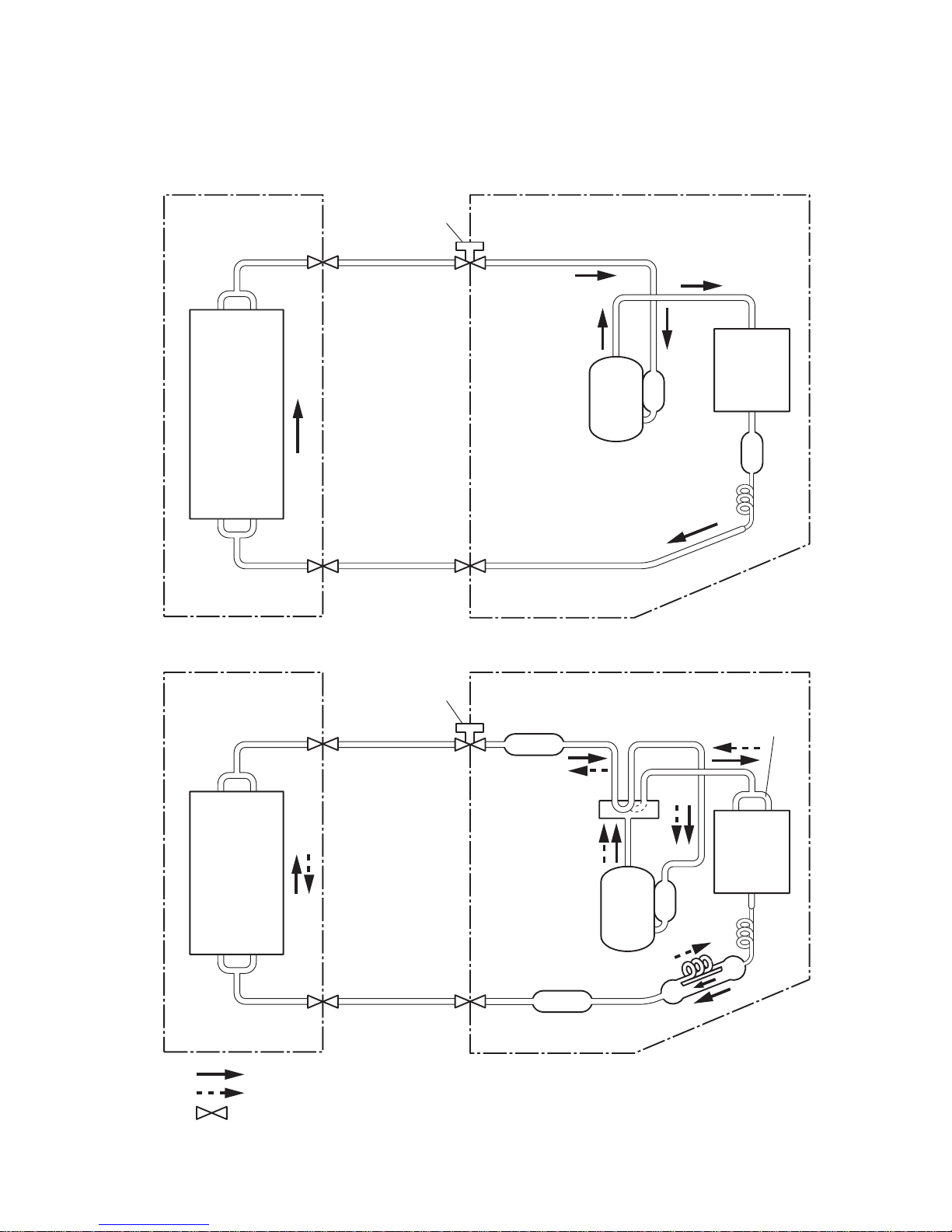
– 72 –
Refrigerant pipe
ø 12.7mm(1/2")
Refrigerant pipe
Suction pipe
ø 6.35mm(1/4")
Capillary
tube
Charging valve
2-Way valve
3-Way
valve
Compressor
Strainer
OUTDOOR UNITINDOOR UNIT
Condenser
Evaporator
Refrigerant pipe
ø 12.7mm(1/2")
Refrigerant pipe
Suction pipe
Coupling
pipe assy
ø 6.35mm(1/4")
Capillary
assy
Charging valve
2-Way
valve
4-Way
valve
3-Way
valve
Compressor
Dryer
Muffler
OUTDOOR UNITINDOOR UNIT
Condenser
Evaporator
Cooling
Heating
: Flare coupling
Models : AS ✽ 14A / AO ✽ 14A
Models : AS ✽ 14R / AO ✽ 14R
Page 74

– 73 –
Refrigerant pipe
Distributor
Distributor
ø 12.7mm(1/2")
Refrigerant pipe
ø 6.35mm(1/4")
Capillary tube
Charging valve
Compressor
Dryer
DryerStrainer
Muffler
Muffler
OUTDOOR UNITINDOOR UNIT
Condenser
Evaporator
Evaporator
Refrigerant pipe
ø 12.7mm(1/2")
Refrigerant pipe
ø 6.35mm(1/4")
Charging valve
Cooling
Heating
: Flare coupling
4-Way
valve
Compressor
Capillary tube
OUTDOOR UNITINDOOR UNIT
Condenser
Accumulator
Models : AS ✽ 17A / AO ✽ 17AB
Models : AS ✽ 17R / AO ✽ 17RB
Page 75

– 74 –
Refrigerant pipe
Distributor
Distributor
ø 12.7mm(1/2")
Refrigerant pipe
ø 6.35mm(1/4")
Capillary tube
Charging valve
Compressor
Dryer
DryerStrainer
OUTDOOR UNITINDOOR UNIT
Condenser
Evaporator
Evaporator
Refrigerant pipe
ø 12.7mm(1/2")
Refrigerant pipe
ø 6.35mm(1/4")
Charging valve
Cooling
Heating
: Flare coupling
4-Way
valve
Compressor
Capillary tube
OUTDOOR UNITINDOOR UNIT
Condenser
Models : AS ✽ 17A / AO ✽ 17AN
Models : AS ✽ 17R / AO ✽ 17RN
Page 76

– 75 –
Refrigerant pipe
Distributor
Distributor
ø 15.88mm(5/8")
Refrigerant pipe
ø 9.53mm(3/8")
Capillary tube
Charging valve
Compressor
Dryer
DryerStrainer
OUTDOOR UNITINDOOR UNIT
Condenser
Evaporator
Evaporator
Refrigerant pipe
ø 15.88mm(5/8")
Refrigerant pipe
ø 9.53mm(3/8")
Charging valve
Cooling
Heating
: Flare coupling
4-Way
valve
Compressor
Capillary tube
OUTDOOR UNITINDOOR UNIT
Condenser
Accumulator
Models : AS ✽ 20A / AO ✽ 20AN
Models : AS ✽ 20R / AO ✽ 20RM
Page 77

– 76 –
Refrigerant pipe
Distributor
Distributor
ø 15.88mm(5/8")
Refrigerant pipe
ø 9.53mm(3/8")
Capillary tube
Charging valve
Compressor
Dryer
DryerStrainer
OUTDOOR UNITINDOOR UNIT
Condenser
Evaporator
Evaporator
Refrigerant pipe
ø 15.88mm(5/8")
Refrigerant pipe
ø 9.53mm(3/8")
Charging valve
Cooling
Heating
: Flare coupling
4-Way
valve
Compressor
Capillary tube
OUTDOOR UNITINDOOR UNIT
Condenser
Accumulator
Models : AS ✽ 24A / AO ✽ 24AN
Models : AS ✽ 24R / AO ✽ 24RM
Page 78

– 77 –
Cooling
Heating
: Flare coupling
Refrigerant pipe
ø 15.88mm(5/8")
Refrigerant pipe
ø 9.53mm(3/8")
Capillary tube
Charging valve
Compressor
Muffler
Dryer
OUTDOOR UNITINDOOR UNIT
Condenser
Check joint
Evaporator
Distributor
Refrigerant pipe
ø 15.88mm(5/8")
Refrigerant pipe
ø 9.53mm(3/8")
Check valve
Capillary tube
Check
valve
Strainer
Charging valve
Compressor
4-Way valve
Accumulator
Muffler
Dryer
OUTDOOR UNITINDOOR UNIT
Condenser
Distributor
Evaporator
Check joint
Distributor
Models : AS ✽ 30A / AO ✽ 30A
Models : AS ✽ 30R / AO ✽ 30R
Page 79

– 78 –
Refrigerant pipe
Distributor
Distributor
ø 15.88mm(5/8")
Refrigerant pipe
ø 9.53mm(3/8")
Capillary tube
Charging valve
Compressor
Dryer
Muffler
OUTDOOR UNITINDOOR UNIT
Condenser
Capillary tube
Compressor
Dryer
Muffler
OUTDOOR UNIT
Condenser
Evaporator
Evaporator
Refrigerant pipe
ø 15.88mm(5/8")
Refrigerant pipe
ø 9.53mm(3/8")
Charging valve
Cooling
: Flare coupling
OUTDOOR UNITINDOOR UNIT
Models : ASC-502B / AOC-502B
Models : ASC-602B / AOC-602B
Page 80

5.1.4
FLOOR / CEILING UNIVERSAL TYPE
– 79 –
Refrigerant pipe
Distributor
Distributor
ø 15.88mm(5/8")
Refrigerant pipe
ø 9.53mm(3/8")
Capillary tube
Charging valve
Compressor
Dryer
OUTDOOR UNITINDOOR UNIT
Condenser
Evaporator
Evaporator
Refrigerant pipe
ø 15.88mm(5/8")
Refrigerant pipe
ø 9.53mm(3/8")
Cooling
Heating
: Flare coupling
INDOOR UNIT
DryerStrainer
Muffler
Muffler
Charging valve
4-Way
valve
Compressor
Capillary tube
OUTDOOR UNIT
Condenser
Accumulator
Models : AB ✽ 24A / AO ✽ 24A
Models : AB ✽ 24R / AO ✽ 24RZ
Page 81

– 80 –
Refrigerant pipe
Distributor
Distributor
ø 15.88mm(5/8")
Refrigerant pipe
ø 9.53mm(3/8")
Capillary tube
Charging valve
Compressor
Dryer
DryerStrainer
OUTDOOR UNITINDOOR UNIT
Condenser
Evaporator
Evaporator
Refrigerant pipe
ø 15.88mm(5/8")
Refrigerant pipe
ø 9.53mm(3/8")
Charging valve
Cooling
Heating
: Flare coupling
4-Way
valve
Compressor
Capillary tube
OUTDOOR UNITINDOOR UNIT
Condenser
Accumulator
Models : AB ✽ 24A / AO ✽ 24AN
Models : AB ✽ 24R / AO ✽ 24RM
Page 82

– 81 –
Refrigerant pipe
Distributor
Distributor
ø 15.88mm(5/8")
Refrigerant pipe
ø 9.53mm(3/8")
Capillary tube
Charging valve
Compressor
Dryer
OUTDOOR UNITINDOOR UNIT
Condenser
Evaporator
Evaporator
Refrigerant pipe
ø 15.88mm(5/8")
Refrigerant pipe
ø 9.53mm(3/8")
Cooling
Heating
: Flare coupling
INDOOR UNIT
DryerStrainer
Muffler
Muffler
Charging valve
4-Way
valve
Compressor
Capillary tube
OUTDOOR UNIT
Condenser
Accumulator
Models : AB ✽ 18A / AO ✽ 18AZ
Models : AB ✽ 18R / AO ✽ 18RZ
Page 83

– 82 –
Refrigerant pipe
Distributor
Distributor
ø 15.88mm(5/8")
Refrigerant pipe
ø 9.53mm(3/8")
Capillary tube
Charging valve
Compressor
Dryer
DryerStrainer
OUTDOOR UNITINDOOR UNIT
Condenser
Evaporator
Evaporator
Refrigerant pipe
ø 15.88mm(5/8")
Refrigerant pipe
ø 9.53mm(3/8")
Charging valve
Cooling
Heating
: Flare coupling
4-Way
valve
Compressor
Capillary tube
OUTDOOR UNITINDOOR UNIT
Condenser
Accumulator
Models : AB ✽ 18A / AO ✽ 18AN
Models : AB ✽ 18R / AO ✽ 18RM
Page 84

– 83 –
Refrigerant pipe
ø 6.35mm(1/4")
Refrigerant pipe
Suction pipe
ø 12.7mm(1/2")
Capillary
tube
Capillary
tube
Charging valve
Charging valve
2-Way valve
3-Way
valve
Compressor
Strainer
OUTDOOR UNITINDOOR UNIT
Condenser
Evaporator
Refrigerant pipe
ø 12.7mm(1/2")
Refrigerant pipe
Suction pipe
Coupling
pipe assy
ø 6.35mm(1/4")
2-Way
valve
4-Way
valve
3-Way
valve
Compressor
Dryer
Muffler
OUTDOOR UNITINDOOR UNIT
Condenser
Evaporator
Cooling
Heating
: Flare coupling
Models : AB ✽ 14A / AO ✽ 14A
Models : AB ✽ 14R / AO ✽ 14R
Page 85

– 84 –
5.2 CIRCUIT DIA GRAM
5.2.1
COMPACT SII SERIES
7
6
5
4
3
2
1
7
6
5
4
3
2
1
7
6
5
4
3
2
1
7
6
5
4
545
4
3
2
1
2
1
212
1
10
9
83
2
1
3
2
1
5
4
3
2
1
5
4
3
2
1
3
2
1
3
2
1
3
2
1
3
2
1
212
1
212
1
2
1
10
9
8
2
1
1
2
3
1
2
3
7
6
5
4
3
2
1
211234567
21 345
21 345
67
21 34567
BLACK
BLACK
BLACK
BLACK
BLACK
GRAY
GRAY
GRAY
GRAY
GRAY
PURPLE
PURPLE
PURPLE
PURPLE
BLUE
BLUE
BLUE
GREEN
GREEN
YELLOW
YELLOW
ORANGE
ORANGE
ORANGE
RED
RED
RED
BROWN
BROWN
BROWN
WHITE
WHITE
WHITE
WHITE
WHITE
BLACK
BLUE
GREEN / YELLOW
RED
BROWN
WHITE
WHITE
WHITE
WHITE
WHITE
WHITE
CONTROL BOARD
POWER SUPPLY BOARD
DISPLAY BOARD
THERMISTOR(ROOM TEMP.)
THERMISTOR
(PIPE TEMP.)
LOUVER
MOTOR
INDOOR UNIT
OUTDOOR UNIT
RELAY
BOARD
THERMAL
FUSE 102°C
THERMAL
FUSE
POWER
RELAY
FAN MOTOR
CAPACITOR
TERMINAL
TRANSFORMER
ORANGE
FAN
MOTOR
CM
FM
FM
M
CN1
TEST
CN106
CN201
CN9
CN301
W301
W104
W103
W101
CN2 CN3CN4
CN5
CN7
CN8
CN102
CN104CN103
CN105
CN101
N
N
L
L
3
4
R
C
S
OVERLOAD RELAYCOMPRESSOR
FAN MOTOR
FAN MOTOR
CAPACITOR
COMPRESSOR
CAPACITOR
BLUE
RED
RED
TERMINAL
WHITE
WHITE
WHITE
BLACK
BLACK
Models : AS ✽ 7A / AO ✽ 7A
Page 86

– 85 –
FAN MOTOR
FAN MOTOR
CAPACITOR
FOUR WAY
VALVE COIL
RED
ORANGE
WHITE
WHITE
WHITE
DARK GRAY
DARK GRAY
FM
SV
CM
COMPRESSOR
TERMINAL
COMPRESSOR
CAPACITOR
BLUE
RED
7
6
5
4
3
2
1
7
6
5
4
3
2
1
7
6
5
4
3
2
1
7
6
5
4
545
4
3
2
1
2
1
212
1
10
9
83
2
1
3
2
1
5
4
3
2
1
5
4
3
2
1
3
2
1
3
2
1
3
2
1
3
2
1
212
1
212
1
2
1
10
9
8
2
1
1
2
3
1
2
3
7
6
5
4
3
2
1
211234567
21 345
21 345
67
21 34567
BLACK
BLACK
BLACK
BLACK
BLACK
GRAY
GRAY
GRAY
GRAY
GRAY
PURPLE
PURPLE
PURPLE
PURPLE
BLUE
BLUE
BLUE
GREEN
GREEN
YELLOW
YELLOW
ORANGE
ORANGE
ORANGE
RED
RED
RED
BROWN
BROWN
BROWN
WHITE
WHITE
WHITE
WHITE
WHITE
BLACK
BLUE
GREEN/YELLOW
RED
BROWN
WHITE
WHITE
WHITE
WHITE
WHITE
WHITE
CONTROL BOARD
POWER SUPPLY BOARD
DISPLAY BOARD
THERMISTOR(ROOM TEMP.)
THERMISTOR
(PIPE TEMP.)
LOUVER
MOTOR
INDOOR UNIT OUTDOOR UNIT
RELAY
BOARD
THERMAL
FUSE 102°C
THERMAL
FUSE
POWER
RELAY
FAN MOTOR
CAPACITOR
TERMINAL
TRANSFORMER
FAN
MOTOR
FM
M
CN1
TEST
CN106
CN201
CN9
CN301
W301
W104
W103
W105
W102
W101
CN2 CN3CN4
CN5
CN7
CN8
CN102
CN104CN103
CN105
CN101
N
L
3
4
BLUE
RED
34
BLACK
BLUE
S
L34N
CR
OVERLOAD RELAY
Models : AS ✽ 7R / AO ✽ 7R
Page 87
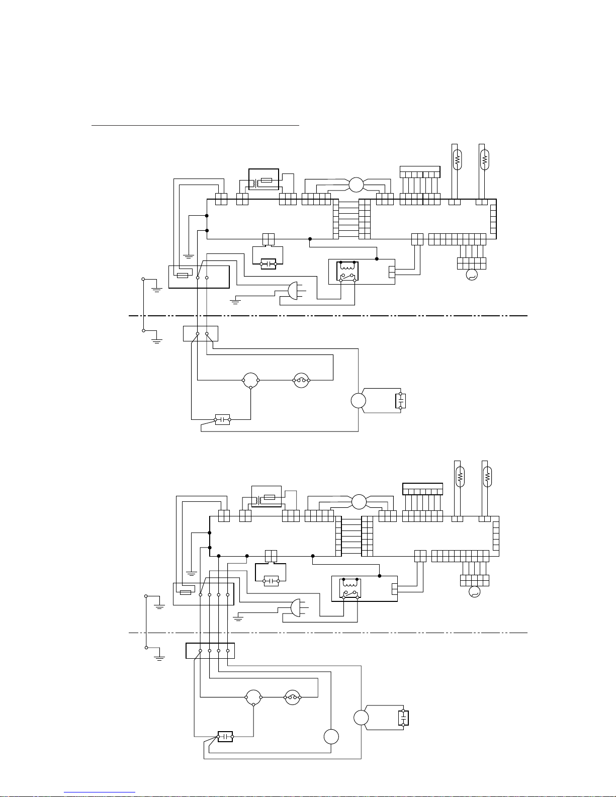
– 86 –
5.2.2
COMPACT MII SERIES
2
2
1
2
3
4
5
6
7
1
2
1
2
3
4
5
6
7
1
2
3
4
5
1
2
3
4
5
6
7
21
2121
21
21
21
21
21
213
213
21123
213
21 345
21 345
21 34567
21 34567
21 34567
21 345678910
21 345678910
12
BLACK
BLACK
BLACK
BLACKBLACK
GRAY
GRAY
BLUE
BLUE
GREEN / YELLOW
YELLOW
ORANGE
RED
RED
RED
BROWN
BROWN
WHITE
WHITE
WHITE
WHITE
WHITE
WHITE
WHITE
WHITE
WHITE
WHITE
WHITE
WHITE
BLACK
BLACK
BLACK
TERMISTOR
(ROOM TEMP.)
TERMISTOR
(PIPE TEMP.)
THERMISTOR
(ROOM TEMP.)
THERMISTOR
(PIPE TEMP.)
BLACK
GRAY
GRAY
GRAY
PURPLE
PURPLE
PURPLE
PURPLE
BLUE
BLUE
GREEN
GREEN
YELLOW
ORANGE
RED
RED
RED
BROWN
BROWN
WHITE
WHITE
CN2 CN3
CN4
CN201
CN201
CN5
CN7
CN8
CN105
CN103
CN104
CN102 CN101
W104
CN1
W103
W101
CN106
CN9
N
N
L
L
RSC
34
BLACK
CM
FM
FM
M
CONTROL BOARD
OVER LOAD
RELAY
POWER SUPPLY BOARD
DISPLAY BOARD
LOUVER MOTOR
TEST
RELAY
BOARD
FAN MOTOR
CAPACITOR
FAN MOTOR
CAPACITOR
TERMINAL
TERMINAL
COMPRESSOR
CAPACITOR
COMPRESSOR
FAN MOTOR
FAN MOTOR
THERMAL
FUSE 102°C
INDOOR UNIT
OUTDOOR UNIT
INDOOR UNIT
OUTDOOR UNIT
TRANSFORMER
THERMAL FUSE
THERMAL FUSE
7
6
5
4
3
2
1
1
2
7
6
5
4
3
2
1
1
2
3
4
5
7
6
5
4
3
2
1
21
2121
21
21
21
21
21
213
213
21123
213
21 345
21 345
21 34567
21 34567
21 34567
21 345678910
21 345678910
12
BLACK
BLACK
DARK GRAY
BLACKBLACK
GRAY
GRAY
BLUE
BLUE
BLUE
BLUE
GREEN / YELLOW
YELLOW
ORANGE
RED
RED
RED
BROWN
BROWN
WHITE
WHITE
WHITE
WHITE
WHITE
WHITE
WHITE
WHITE
WHITE
WHITE
WHITE
WHITE
WHITE
BLACK
BLACK
BLACK
BLACK
GRAY
GRAY
GRAY
PURPLE
PURPLE
PURPLE
PURPLE
BLUE
BLUE
GREEN
GREEN
YELLOW
ORANGE
RED
RED
RED
RED
BROWN
ORANGE
ORANGE
BROWN
WHITE
WHITE
CN2 CN3
CN4
CN5
CN7
CN8
CN105
CN103
CN104
CN102 CN101
W104W102
CN1
W103
W101
CN106
CN9
N
N34
L
L
R
C
S
CM
FM
FM
SV
M
CONTROL BOARDPOWER SUPPLY BOARD
DISPLAY BOARD
LOUVER MOTOR
TEST
RELAY
BOARD
FAN MOTOR
CAPACITOR
TERMINAL
TERMINAL
COMPRESSOR
CAPACITOR
COMPRESSOR
OVER LORD
RELAY
FAN MOTOR
FAN
MOTOR
THERMAL
FUSE 102°C
TRANSFORMER
FOUR WAY
VALVE COIL
FAN MOTOR
CAPACITOR
W301
W105
43
21 345
21 345
ORANGE
ORANGE
CN301
21 345
21 345
W301
43
POWER
RELAY
POWER
RELAY
Models : AS ✽ 9A / AO ✽ 9A
Models : AS ✽ 9R / AO ✽ 9R
Page 88
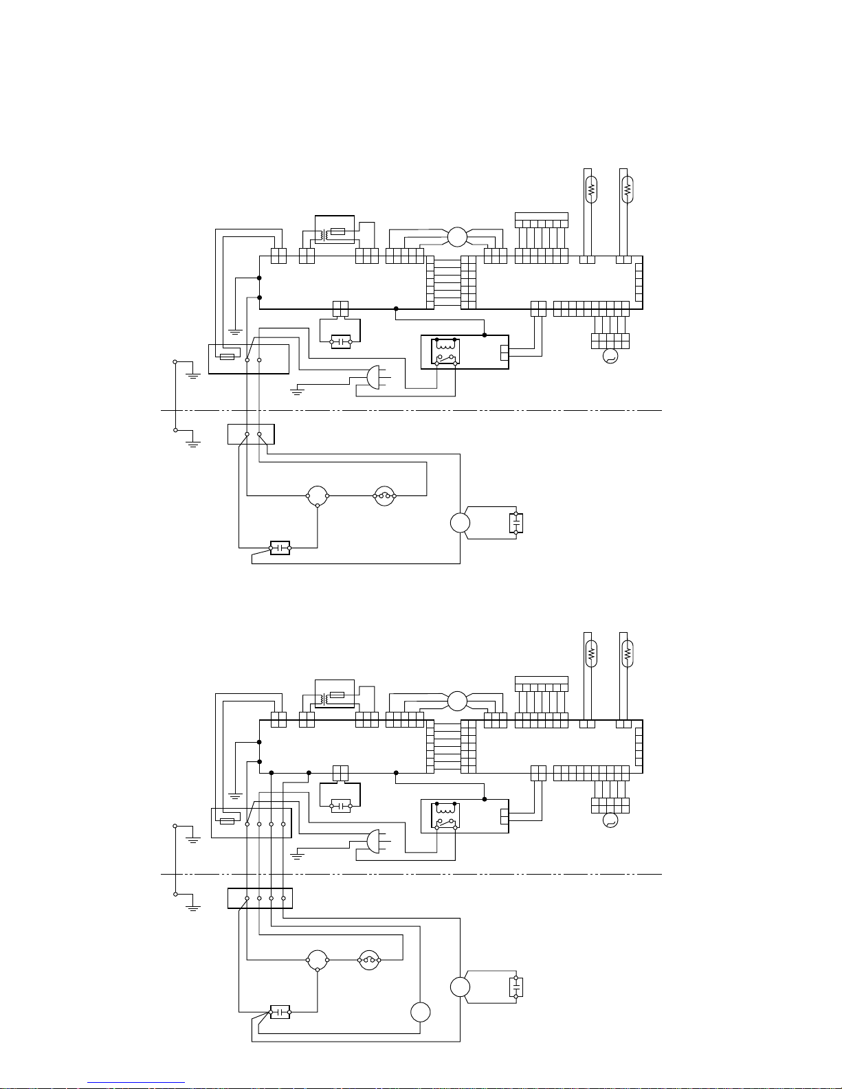
– 87 –
2
2
INDOOR UNIT
OUTDOOR UNIT
INDOOR UNIT
OUTDOOR UNIT
1
2
3
4
5
6
7
1
43
43
2
1
2
3
4
5
6
7
1
2
3
4
5
1
2
3
4
5
6
7
21
2121
21
21
21
21
21
213
213
21213
213
21 345
21 345
21 34567
21 34567
21 34567
21 345678910
21 345678910
12
BLACK
BLACK
BLACK
BLACKBLACK
GRAY
GRAY
BLUE
BLUE
GREEN / YELLOW
YELLOW
ORANGE
RED
RED
RED
BROWN
ORANGE
ORANGE
BROWN
WHITE
WHITE
WHITE
WHITE
WHITE
WHITE
WHITE
WHITE
WHITE
WHITE
WHITE
WHITE
BLACK
BLACK
BLACK
BLACK
GRAY
GRAY
GRAY
PURPLE
PURPLE
PURPLE
PURPLE
BLUE
BLUE
GREEN
GREEN
YELLOW
ORANGE
RED
RED
RED
BROWN
BROWN
WHITE
WHITE
CN2 CN3
CN4
CN5
CN7
CN8
CN105
CN103
CN104
CN102 CN101
W104
CN1
W103
W101
CN106
CN9
N
N
L
L
RCS
34
BLACK
CM
FM
FM
M
CONTROL BOARD
OVERLOAD
RELAY
POWER SUPPLY BOARD
DISPLAY BOARD
LOUVER MOTOR
TEST
RELAY
BOARD
FAN MOTOR
CAPACITOR
FAN MOTOR
CAPACITOR
TERMINAL
TERMINAL
COMPRESSOR
CAPACITOR
COMPRESSOR
FAN MOTOR
FAN MOTOR
THERMAL
FUSE 102°C
1
2
3
4
5
6
7
1
2
1
2
3
4
5
6
7
1
2
3
4
5
1
2
3
4
5
6
7
21
2121
21
21
21
21
21
213
213
21213
213
21 345
21 345
21 34567
21 34567
21 34567
21 345678910
21 345678910
12
BLACK
BLACK
DARK GRAY
BLUE
BLACKBLACK
GRAY
GRAY
BLUE
BLUE
GREEN / YELLOW
YELLOW
ORANGE
RED
RED
RED
BROWN
BROWN
WHITE
WHITE
WHITE
WHITE
WHITE
WHITE
WHITE
WHITE
WHITE
WHITE
WHITE
WHITE
BLACK
BLACK
BLACK
BLACK
GRAY
GRAY
THERMISTOR
(ROOM TEMP.)
THERMISTOR
(PIPE TEMP.)
THERMISTOR
(ROOM TEMP.)
THERMISTOR
(PIPE TEMP.)
GRAY
PURPLE
PURPLE
PURPLE
PURPLE
BLUE
BLUE
GREEN
GREEN
YELLOW
ORANGE
RED
RED
RED
BROWN
BROWN
WHITE
WHITE
CN2 CN3
CN4
CN5
CN7
CN8
CN105
CN103
CN104
CN102 CN101
W104W105 W102
CN1
W103
W101
CN106
CN9
N
N34
L
L
RCS
CM
FM
FM
SV
M
CONTROL BOARD
OVERLOAD
RELAY
POWER SUPPLY BOARD
DISPLAY BOARD
LOUVER MOTOR
TEST
POWER
RELAY
RELAY
BOARD
POWER
RELAY
FAN MOTOR
CAPACITOR
TERMINAL
TERMINAL
COMPRESSOR
CAPACITOR
COMPRESSOR
FAN MOTOR
FAN
MOTOR
THERMAL
FUSE 102°C
FOUR WAY
VALVE COIL
FAN MOTOR
CAPACITOR
21345
21345
ORANGE
ORANGE
CN301
TRANSFORMER
THERMAL FUSE
TRANSFORMER
THERMAL FUSE
21345
21345
Models : AS ✽ 12A / AO ✽ 12A
Models : AS ✽ 12R / AO ✽ 12R
Page 89

5.2.3
COMPACT LI SERIES
– 88 –
2
2
1
2
3
4
5
6
7
1
2
1
2
3
4
5
6
7
1
2
3
4
5
1
2
3
4
5
6
7
21
2121
21
21
21
21
21
213
213
21123
213
21 345
21 345
21 34567
21 34567
21 34567
21 345678910
21 345678910
12
12
BLACK
BLACK
BLACK
BLACKBLACK
GRAY
GRAY
BLUE
BLUE
GREEN / YELLOW
YELLOW
ORANGE
RED
RED
RED
BROWN
BROWN
WHITE
WHITE
WHITE
WHITE
WHITE
WHITE
WHITE
WHITE
WHITE
WHITE
WHITE
WHITE
BLACK
BLACK
BLACK
TERMISTOR
(ROOM TEMP.)
TERMISTOR
(PIPE TEMP.)
THERMISTOR
(ROOM TEMP.)
THERMISTOR
(PIPE TEMP.)
BLACK
GRAY
GRAY
GRAY
PURPLE
PURPLE
PURPLE
PURPLE
BLUE
BLUE
GREEN
GREEN
YELLOW
ORANGE
RED
RED
RED
BROWN
BROWN
WHITE
WHITE
CN2 CN3
CN4
CN201
CN201
CN5
CN7
CN8
CN105
CN103
CN104
CN102 CN101
W104
CN1
W103
W101
CN106
CN9
N
N
L
L
RSC
34
BLACK
CM
FM
FM
M
CONTROL BOARD
OVER LOAD
RELAY
POWER SUPPLY BOARD
DISPLAY BOARD
LOUVER MOTOR
TEST
RELAY
BOARD
FAN MOTOR
CAPACITOR
FAN MOTOR
CAPACITOR
TERMINAL
TERMINAL
COMPRESSOR
CAPACITOR
COMPRESSOR
FAN MOTOR
FAN MOTOR
THERMAL
FUSE 102°C
INDOOR UNIT
OUTDOOR UNIT
INDOOR UNIT
OUTDOOR UNIT
TRANSFORMER
THERMAL FUSE
THERMAL FUSE
7
6
5
4
3
2
1
1
2
7
6
5
4
3
2
1
1
2
3
4
5
7
6
5
4
3
2
1
21
2121
21
21
21
21
21
213
213
2123
213
21 345
21 345
21 34567
21 34567
21 34567
21 345678910
21 345678910
11
21
2
BLACK
BLACK
DARK GRAY
BLACKBLACK
GRAY
GRAY
BLUE
BLUE
BLUE
BLUE
GREEN / YELLOW
YELLOW
ORANGE
RED
RED
RED
BROWN
BROWN
WHITE
WHITE
WHITE
WHITE
WHITE
WHITE
WHITE
WHITE
WHITE
WHITE
WHITE
WHITE
WHITE
BLACK
BLACK
BLACK
BLACK
GRAY
GRAY
GRAY
PURPLE
PURPLE
PURPLE
PURPLE
BLUE
BLUE
GREEN
GREEN
YELLOW
ORANGE
RED
RED
RED
RED
BROWN
ORANGE
ORANGE
BROWN
WHITE
WHITE
CN2 CN3
CN4
CN5
CN7
CN8
CN105
CN103
CN104
CN102 CN101
W104W102
CN1
W103
W101
CN106
CN9
N
N34
L
L
R
C
S
CM
FM
FM
SV
M
CONTROL BOARDPOWER SUPPLY BOARD
DISPLAY BOARD
LOUVER MOTOR
TEST
RELAY
BOARD
FAN MOTOR
CAPACITOR
TERMINAL
TERMINAL
COMPRESSOR
CAPACITOR
COMPRESSOR
OVER LORD
RELAY
FAN MOTOR
FAN
MOTOR
THERMAL
FUSE 102°C
TRANSFORMER
FOUR WAY
VALVE COIL
FAN MOTOR
CAPACITOR
W301
W105
43
21 345
21 345
ORANGE
ORANGE
CN301
21 345
21 345
W301
43
POWER
RELAY
POWER
RELAY
12
Models : AS ✽ 14A / AO ✽ 14A
Models : AS ✽ 14R / AO ✽ 14R
Page 90

– 89 –
RED
RED
12345
TERMINAL
TERMINAL
TEST
CN 11
CN 13
43
POWER
RELAY
CONTROL BOARD
POWER SUPPLY
BOARD
THERMISTOR (PIPE TEMP.)
THERMISTOR (ROOM TEMP.)
STEP
MOTOR
FAN MOTOR
COMPRESSOR
COMPRESSOR
CAPACITOR
FAN
MOTOR
DISPLAY BOARD
BLACK
BLACK
GRAY
GRAY
BLUE
WHITE
WHITE
WHITE
WHITE
WHITE
WHITE
BLUE
WHITE
BLUE
WHITE
WHITE
WHITE
WHITE
WHITE
BLACK
GRAY
GRAY
12N
WHITE
GREEN
GREEN/YELLOW
WHITE
WHITE
WHITE
WHITE
BLACK
PURPLE
PURPLE
BROWN
Use T 3.15A–250V
fuse on F101
RED
RED
ORANGE
WHITE
WHITE
WHITE
WHITE
WHITE
WHITE
BLUE
ORANGE
YELLOW
PINK
RED
2 1
CN 12CN 8
CN 9
2 1
2 1
12345
1
2
3
4
5
1
2
3
4
5
1 2 3 4 5 6 7
12345
CN 105
E
1 2
CN 106
1 2
1 2
2 2
1 1
3
CN 103
1 2 3
1 2
CN 102
W103 W102
W101
1 2
1 2
CN 101
1 2
1 2 3
4 5
12345 67
1234567
6
7
8
1
2
3
4
5
6
7
8
CN 16
CN 107
CN 201
1
2
3
4
5
6
7
8
M
FM
THERMAL
PROTECTOR
THERMAL
PROTECTOR
TRANSFORMER
THERMAL FUSE
THERMAL
FUSE 102°C
BLACK BLACK
GREEN/YELLOW
12345
INDOOR UNIT
OUTDOOR UNIT
OVERLOAD
PROTECTOR
C
R
S
TERMINAL
TERMINAL
1
(N)
2
3
4
RED
RED
WHITE
WHITE
BLACK
BLACK
BLACK
BLACK
WHITE
WHITE
COMPRESSOR
CAPACITOR
FAN MOTOR
CAPACITOR
COMPRESSOR
THERMAL
PROTECTOR
FAN
MOTOR
4-WAY
VALVE COIL
TEST
CN 11
CN 13
43
POWER
RELAY
CONTROL BOARD
POWER SUPPLY
BOARD
THERMISTOR (PIPE TEMP.)
THERMISTOR (ROOM TEMP.)
STEP
MOTOR
FAN
MOTOR
DISPLAY BOARD
BLACK
BLACK
GRAY
GRAY
BLUE
WHITE
WHITE
WHITE
WHITE
WHITE
WHITE
BLUE
WHITE
BLUE
BLUE
WHITE
RED
BLACK
GRAY
GRAY
12N
WHITE
GREEN
GREEN/YELLOW
GREEN/YELLOW
WHITE
WHITE
WHITE
WHITE
BLACK
PURPLE
PURPLE
BROWN
Use T 3.15A–250V
fuse on F101
RED
RED
ORANGE
WHITE
WHITE
WHITE
WHITE
WHITE
WHITE
BLUE
ORANGE
YELLOW
PINK
RED
2 1
CN 12CN 8
CN 9
2 1
2 1
12345
1
2
3
4
5
1
2
3
4
5
1 2 3 4 5 6 7
12345
CN 105
E
1 2
CN 106
1 2
1 2
2 2
1 1
3
CN 103
1 2 3
1 2
CN 102
W103 W102
W101
1 2
1 2
CN 101
1 2
1 2 3
4 5
12345 67
1234567
6
7
8
1
2
3
4
5
6
7
8
CN 16
CN 107
CN 201
1
2
3
4
5
6
7
8
M
FM
SV
3
4
THERMAL
PROTECTOR
TRANSFORMER
THERMAL FUSE
THERMAL
FUSE 102°C
Models : AS ✽ 14A / AO ✽ 14A
Models : AS ✽ 14R / AO ✽ 14R
Page 91

– 90 –
WHITE
BLACK
ORANGE
BLUE
ORANGE
YELLOW
PINK
RED
12345
INDOOR UNIT
OUTDOOR UNIT
TERMINAL
TERMINAL
2
(N)
1
(L)
N
L
WHITE
3
TEST
CN 11
CN 13
43
POWER
RELAY
CONTROL BOARD
POWER SUPPLY
BOARD
THERMISTOR (PIPE TEMP.)
THERMISTOR (ROOM TEMP.)
STEP
MOTOR
FAN
MOTOR
DISPLAY BOARD
BLACK
BLACK
GRAY
GRAY
BLUE
WHITE
WHITE
WHITE
WHITE
WHITE
WHITE
BLUE
WHITE
BLUE
BLUE
BLUE
BLACK
BROWN
BROWN
BLACK
BLACK
WHITE
BLACK
GRAY
GRAY
12(L)
(N)
GREEN
YELLOW/GREEN
WHITE
WHITE
WHITE
WHITE
PURPLE
PURPLE
BROWN
Use T 3.15A – 250V
fuse on F101
RED
RED
WHITE
WHITE
WHITE
WHITE
WHITE
WHITE
2 1
CN 12CN 8
CN 9
2 1
2 1
12345
1
2
3
4
5
1
2
3
4
5
1 2 3 4 5 6 7
12345
CN 105
E
1 2
CN 106
1 2
1 2
2 2
1 1
3
CN 103
1 2 3
1 2
CN 102
W103 W102
W101
1 2
1 2
CN 101
1 2
1 2 3
4 5
12345 67
1234567
6
7
8
1
2
3
4
5
6
7
8
CN 16
CN 107
CN 201
1
2
3
4
5
6
7
8
M
FM
3
4
THERMAL
PROTECTOR
TRANSFORMER
THERMAL FUSE
THERMAL
FUSE 102°C
TO POWER SUPPLY
MAIN RELAY
FUSE 5A
RED
RED
WHITE
WHITE
WHITE
FAN MOTOR
CAPACITOR
COMPRESSOR
CAPACITOR
INTERNAL
OVERLOAD
PROTECTOR
COMPRESSOR
THERMAL
PROTECTOR
FAN
MOTOR
1
4
5
6
C
R
S
Models : AS ✽ 17A / AO ✽ 17AN
Page 92

– 91 –
THERMISTOR (PIPE TEMP.)
THERMISTOR (ROOM TEMP.)
BROWN
RED
RED
ORANGE
CONTROL BOARD
STEP MOTOR
(UP/DOWN)
INDOOR UNIT
OUTDOOR UNIT
FAN MOTOR
CAPACITOR
YELLOW
WHITE
WHITE
BROWN
RED
ORANGE
YELLOW
WHITE
BLACK
GRAY
GRAY
GREEN/YELLOW
GREEN/YELLOW
BLUE
BLUE
DISPLAY BOARD
PURPLE
PURPLE
WHITE
WHITE
GREEN
CN13
1234567
CN10
12345
CN4
12
CN7
12
CN12
13
CN2
3 2 1
BLACK
BLACK
CN8
12
CN3
12
1234567
CN201
M
STEP MOTOR
(LEFT/RIGHT)
BROWN
RED
ORANGE
RED
RED
CN1
12
BLACK
BLACK
N
L
BLACK
BLACK
WHITE
WHITE
YELLOW
WHITE
CN11
1
GRAY
GRAY
2345
M
FAN MOTOR
MAIN RELAY
THERMAL
FUSE 102°C
FILTER BOARD
TERMINAL
CN5
123456
FM
1
(L)
2
(N)
3
Use T3.15A–250V
Fuse on F101
TERMINAL
2
(N)
1
(L)
N
L
WHITE
3
BLUE
BLUE
BLUE
BLACK
BROWN
BROWN
BLACK
BLACK
YELLOW/GREEN
TO POWER SUPPLY
MAIN RELAY
FUSE 5A
RED
RED
WHITE
WHITE
WHITE
FAN MOTOR
CAPACITOR
COMPRESSOR
CAPACITOR
INTERNAL
OVERLOAD
PROTECTOR
COMPRESSOR
THERMAL
PROTECTOR
FAN
MOTOR
1
4
5
6
C
R
S
Models : AS ✽ 20A / AO ✽ 20AN
Models : AS ✽ 24A / AO ✽ 24AN
Page 93

– 92 –
5.2.4
W ALL MOUNTED LARGE TYPE
INDOOR UNIT
OUTDOOR UNIT
3
2
22
11
11
5432176
BLACK
BLACK
BLACK
GRAY
GRAY
RED
RED
WHITE
WHITE
BLACK
BLACK
BLACK
GRAY
GRAY
PURPLE
PURPLE
BLUE
BLUE
BLUE
GREEN
YELLOW
ORANGE
RED
RED
BROWN
BROWN
WHITE
WHITE
WHITE
WHITE
YELLOW
ORANGE
RED
BROWN
WHITE
YELLOW
ORANGE
RED
BROWN
WHITE
CN2
CN11 CN10
CN3
CN13
CN4
CN5
CN1
CN201
CN7
CN8
CN12
FM
CONTROL BOARD
INTERNAL
OVERLOAD
PROTECTOR
THERMAL
PROTECTOR
DISPLAY BOARD
THERMISTOR(ROOM TEMP.)
THERMISTOR(PIPE TEMP.)
MAIN RELAY
FILTER
BOARD
Use T3.15A-250V
Fuse on F101
FAN MOTOR
FAN MOTOR CAPACITOR
TERMINAL
STEP MOTOR
(UP/DOWN)
STEP MOTOR
(LEFT/RIGHT)
COMPRESSOR
CAPACITOR
FAN MOTOR
CAPACITOR
COMPRESSOR
FAN
MOTOR
THERMAL
FUSE 102°C
MM
GREEN / YELLOW
GREEN / YELLOW
GREEN/YELLOW
BLACK
BLACK
WHITE
WHITE
RED
RED
WHITE
WHITE
1(N) 2
R
C
S
YELLOW / GREEN
2
1
L
N
5432176543216
21
321
21
54321 54321
Models : AS ✽ 20A / AO ✽ 20AZ (except ASC-502B / AOC-502B and ASC-602B / AOC-602B)
Models : AS ✽ 24A / AO ✽ 24AB
Page 94

– 93 –
3
2
22
11
11
321
2
1
54321
54321
2
1
54321
7
6
54321
7
6
54321
6
BLACK
BLACK
BLACK
GRAY
GRAY
RED
RED
WHITE
WHITE
BLACK
BLACK
BLACK
GRAY
GRAY
PURPLE
PURPLE
WHITE
BLUE
BLUE
GREEN
YELLOW
ORANGE
RED
RED
RED
BROWN
WHITE
WHITE
WHITE
WHITE
YELLOW
ORANGE
RED
BROWN
WHITE
YELLOW
ORANGE
RED
BROWN
WHITE
CN2
CN11 CN10
CN3
CN13
CN4
OUTDOOR UNIT
INDOOR UNIT
CN5
CN1
CN201
CN7
CN8
CN12
FM
CONTROL BOARD
DISPLAY BOARD
THERMISTOR(ROOM TEMP.)
THERMISTOR(PIPE TEMP.)
MAIN RELAY
FILTER
BOARD
Use T3.15A-250V
Fuse on F101
FAN MOTOR CAPACITOR
STEP MOTOR
(LEFT/RIGHT)
STEP MOTOR
(UP/DOWN)
FAN
MOTOR
THERMAL
FUSE 102°C
MM
GREEN/YELLOW
GREEN/YELLOW
GREEN/YELLOW
INTERNAL
OVERLOAD
PROTECTOR
THERMAL
PROTECTOR
FAN MOTOR
COMPRESSOR
CAPACITOR
FAN MOTOR
CAPACITOR
COMPRESSOR
BLACK
BLACK
WHITE
RED
RED
WHITE
WHITE
TERMINAL
WHITE
1(N) 2
C
R
S YELLOW/GREEN
12
L
N
Models : ASC-502B / AOC-502B
Models : ASC-602B / AOC-602B
Page 95

– 94 –
INDOOR UNIT
OUTDOOR UNIT
22
11
22
11
BLACK
BLACK
BLACK
GRAY
GRAY
RED
RED
WHITE
WHITE
BLACK
BLACK
BLACK
GRAY
GRAY
PURPLE
PURPLE
BLUE
BLUE
BLUE
GREEN
YELLOW
ORANGE
RED
RED
BROWN
BROWN
WHITE
WHITE
WHITE
WHITE
YELLOW
ORANGE
RED
BROWN
WHITE
YELLOW
ORANGE
RED
BROWN
WHITE
CN2
CN11 CN10
CN3
CN13
CN4
CN5
CN1
CN7
CN8
CN12
FM
CONTROL BOARD
Use T3. 15A-250V
Fuse on F101
INTERNAL
OVERLOAD
PROTECTOR
THERMAL
PROTECTOR
DISPLAY BOARD
THERMISTOR(ROOM TEMP.)
THERMISTOR(PIPE TEMP.)
MAIN RELAY
FILTER
BOARD
FAN MOTOR
FAN MOTOR CAPACITOR
TERMINAL
COMPRESSOR
CAPACITOR
FAN MOTOR
CAPACITOR
COMPRESSOR
FAN
MOTOR
THERMAL
FUSE 102°C
GREEN / YELLOW
GREEN / YELLOW
BLACK
BLACK
BLACK
BLACK
WHITE
WHITE
RED
WHITE
WHITE
1(N) 2
R
C
S
YELLOW / GREEN
RED
BLACK
BLUE
RED
BROWN
1
L
N
2
33445
5
FOUR WAY VALVE
SV
21
5432154321
21321
543216
5432176
5432176
STEP MOTOR
(UP/DOWN)
STEP MOTOR
(LEFT/RIGHT)
M M
Models : AS ✽ 20R / AO ✽ 20R
Models : AS ✽ 24R / AO ✽ 24R
(except “ASB” model)
Page 96

– 95 –
OUTDOOR UNIT
INDOOR UNIT
INTERNAL
OVERLOAD
PROTECTOR
THERMAL
PROTECTOR
FAN MOTOR
COMPRESSOR
CAPACITOR
FAN MOTOR
CAPACITOR
COMPRESSOR
BLACK
WHITE
WHITE
BLACK
RED
WHITE
WHITE
C
R
S
YELLOW/GREEN
BLACK
BLACK
BLACK
SV
Use T3.15A-250V
Fuse on F101
3
2
22
11
11
321
2
1
54321
54321
2
1
54321
7
6
54321
7
6
54321
6
BLACK
BLACK
BLACK
GRAY
GRAY
RED
RED
WHITE
WHITE
BLACK
BLACK
BLACK
GRAY
GRAY
PURPLE
PURPLE
BLUE
BLUE
BLUE
GREEN
YELLOW
ORANGE
RED
RED
BROWN
BROWN
WHITE
WHITE
WHITE
WHITE
YELLOW
ORANGE
RED
BROWN
WHITE
YELLOW
ORANGE
RED
BROWN
WHITE
CN2
CN11 CN10
CN3
CN13
CN4
CN5
CN1
CN7
CN8
CN12
FM
CONTROL BOARD
DISPLAY BOARD
THERMISTOR(ROOM TEMP.)
THERMISTOR(PIPE TEMP.)
MAIN RELAY
FILTER
BOARD
FAN MOTOR CAPACITOR
STEP MOTOR
(LEFT/RIGHT)
STEP MOTOR
(UP/DOWN)
FAN
MOTOR
THERMAL
FUSE 102°C
M
M
GREEN/YELLOW
GREEN/YELLOW
BLUE
RED
BROWN
1
23
4
5
4 - WAY VALVE
GREEN/YELLOW
L
N
TERMINAL 1(N) 2
34 5
Models : ASB24R / AOB24R
Page 97

– 96 –
INDOOR UNIT
OUTDOOR UNIT
3
2
22
11
11
BLACK
BLACK
BLACK
GRAY
GRAY
RED
RED
WHITE
WHITE
BLACK
BLACK
BLACK
GRAY
GRAY
PURPLE
PURPLE
BLUE
BLUE
GREEN
YELLOW
ORANGE
RED
RED
BROWN
WHITE
WHITE
WHITE
WHITE
YELLOW
ORANGE
RED
BROWN
WHITE
YELLOW
ORANGE
RED
BROWN
WHITE
CN2
CN11 CN10
CN3
CN13
CN4
CN5
CN1
CN201
CN7
CN8
CN12
FM
CONTROL BOARD
INTERNAL
OVERLOAD
PROTECTOR
THERMAL
PROTECTOR
DISPLAY BOARD
THERMISTOR(ROOM TEMP.)
THERMISTOR(PIPE TEMP.)
MAIN RELAY
TERMINAL
FILTER
BOARD
FAN MOTOR
FAN MOTOR
CAPACITOR
STEP MOTOR
(UP/DOWN)
STEP MOTOR
(LEFT/RIGHT)
COMPRESSOR
CAPACITOR
MAIN RELAY
TERMINAL
TO POWER SUPPLY
FAN MOTOR
CAPACITOR
COMPRESSOR
FAN
MOTOR
THERMAL
FUSE 102°C
GREEN / YELLOW
GREEN / YELLOW
BLACK
WHITE
WHITE
RED WHITE
1
(L)
2
(N)
R
C
S
1
(L)
2
(N)
3
HL
C
3
BLACK
BLACK
BLACK
BROWN
BROWN
WHITE
BLACK
BLACK
BLACK
WHITE
BLUE
RED
CONNECTOR
OUTDOOR
THERMOSTAT
NL
N
L
GREEN / YELLOW
1
4
5
6
321
21 54321
54321
21
543216
5432176
5432176
MM
Use T3.15A-250V
Fuse on F101
FUSE 5A
Models : AS ✽ 30A / AO ✽ 30A (except "ASB" model )
Page 98

– 97 –
3
2
2
2
11
11
321
21
54321
54321
215432176
5432176
543216
BLACK
BLACK
BLACK
GRAY
GRAY
RED
RED
WHITE
WHITE
BLACK
BLACK
BLACK
GRAY
GRAY
PURPLE
PURPLE
BLUE
BLUE
BLUE
GREEN
YELLOW
ORANGE
RED
RED
BROWN
BROWN
WHITE
WHITE
WHITE
WHITE
YELLOW
ORANGE
RED
BROWN
WHITE
YELLOW
ORANGE
RED
BROWN
WHITE
CN2
CN11 CN10
CN3
CN13
CN4
OUTDOOR UNIT
INDOOR UNIT
CN5
CN1
CN201
CN7
CN8
CN12
FM
CONTROL BOARD
DISPLAY BOARD
THERMISTOR(ROOM TEMP.)
THERMISTOR(PIPE TEMP.)
MAIN RELAY
FILTER
BOARD
FAN MOTOR CAPACITOR
STEP MOTOR
(LEFT/RIGHT)
STEP MOTOR
(UP/DOWN)
FAN
MOTOR
THERMAL
FUSE 102°C
M
M
GREEN/YELLOW
GREEN/YELLOW
GREEN/YELLOW
12
L
N
Use T3.15A-250V
Fuse on F101
INTERNAL
OVERLOAD
PROTECTOR
THERMAL
PROTECTOR
FAN MOTOR
CONNECTOR
COMPRESSOR
CAPACITOR
FAN MOTOR
CAPACITOR
TERMINAL
COMPRESSOR
BLACK
WHITE
WHITE
RED
WHITE
R
C
S
21 (N)
RED
BLUE
BLACK
WHITE
Models : ASB30A / AOB30A
Page 99

– 98 –
3
2
22
11
11
BLACK
BLACK
BLACK
GRAY
GRAY
RED
RED
WHITE
WHITE
BLACK
BLACK
BLACK
GRAY
GRAY
PURPLE
PURPLE
BLUE
BLUE
BLUE
GREEN
YELLOW
ORANGE
RED
RED
RED
BROWN
WHITE
WHITE
WHITE
WHITE
YELLOW
ORANGE
RED
BROWN
BROWN
WHITE
YELLOW
ORANGE
RED
BROWN
WHITE
CN2
CN11 CN10
CN3
CN13
CN4
CN5
CN1
CN7
CN201
CN8
CN12
FM
CONTROL BOARD
Use T3. 15A-250V
Fuse on F1
INTERNAL
OVERLOAD
PROTECTOR
THERMAL
PROTECTOR
DISPLAY BOARD
THERMISTOR(ROOM TEMP.)
THERMISTOR(PIPE TEMP.)
MAIN RELAY
FILTER
BOARD
FAN MOTOR
FAN MOTOR
CAPACITOR
CONNECTOR
FAN MOTOR CAPACITOR
STEP MOTOR
(UP/DOWN)
STEP MOTOR
(LEFT/RIGHT)
COMPRESSOR
CAPACITOR
MAIN RELAY
TERMINAL
TO POWER SUPPLY
COMPRESSOR
4-WAY VALVE
FAN MOTOR
TERMINAL
THERMAL
FUSE 102°C
SV
GREEN / YELLOW
GREEN / YELLOW
BLACK
WHITE
WHITE
WHITE
RED
WHITE
1
(L)
1
2
(N)
R
C
S
1
(L)
2
(N)
3
5
5
6
6
4
4
3
4
56
BLUE
BLACK
WHITE
BLACK
BROWN
BLUE
BLUE
BLACK
BROWN
BROWN
WHITE
BLACK
BLUE
BLUE
RED
NL
N
L
21
54321
5432121321
543216
5432176
5432176
INDOOR UNIT
OUTDOOR UNIT
MM
Use T3.15A-250V
Fuse on F101
BLACK
BLACK
FUSE 5A
CONNECTOR
BELT
HEA TER
RELAY
5
8
1
7
Models : AS ✽ 30R / AO ✽ 30R (except "ASB" model )
Page 100

– 99 –
3
2
22
11
11
321
2
1
54321
54321
2
1
54321
7
6
54321
7
6
54321
6
BLACK
BLACK
BLACK
GRAY
GRAY
RED
RED
WHITE
WHITE
BLACK
BLACK
BLACK
GRAY
GRAY
PURPLE
PURPLE
WHITE
BLUE
BLUE
GREEN
YELLOW
ORANGE
RED
RED
RED
BROWN
WHITE
WHITE
WHITE
WHITE
YELLOW
ORANGE
RED
BROWN
WHITE
YELLOW
ORANGE
RED
BROWN
WHITE
CN2
CN11 CN10
CN3
CN13
CN4
OUTDOOR UNIT
INDOOR UNIT
CN5
CN1
CN201
CN7
CN8
CN12
FM
CONTROL BOARD
DISPLAY BOARD
THERMISTOR(ROOM TEMP.)
THERMISTOR(PIPE TEMP.)
MAIN RELAY
FILTER
BOARD
FAN MOTOR CAPACITOR
STEP MOTOR
(LEFT/RIGHT)
STEP MOTOR
(UP/DOWN)
FAN
MOTOR
THERMAL
FUSE 102°C
MM
GREEN/YELLOW
GREEN/YELLOW
GREEN/YELLOW
12345
L
N
BLUE
RED
BROWN
Use T3.15A-250V
Fuse on F101
INTERNAL
OVERLOAD
PROTECTOR
THERMAL
PROTECTOR
FAN MOTOR
CONNECTOR
COMPRESSOR
CAPACITOR
COMPRESSOR
CAPACITOR
TERMINAL
COMPRESSOR
SV
BLACK
WHITE
WHITE
RED
WHITE
34
R
C
S
521 (N)
RED
BLUE
BLACK
WHITE
Models : ASB30R / AOB30R
 Loading...