

Fujitsu AS*9LSACW, AS*12LSACW, AS*14LSBCW, AS*18LSBCW, AO*9LSAC Service Instructions Manual
...Page 1
SPLIT TYPE
ROOM AIR CONDITIONER
WALL MOUNTED
type
Models Indoor unit Outdoor unit
AS*9LSACW
AS*12LSACW
AS*9LSBCW
AS*12LSBCW
AS*14LSBCW
AS*18LSBCW
AO*9LSAC
AO*12LSAC
AO*9LFBC
AO*12LFBC
AOY14LFBC
AO*18LFBC
INVERTER
SERVICE
INSTRUCTION
R410A
Page 2

CONTENTS
1. SPECIFICATION
AS*14/ 18LSBC, AO*14 / 18LFBC..................................................................................01-03
AS*9 / 12LSAC, AO*9 / 12LSAC.....................................................................................02-01
2. DIMENSIONS
AS*9 / 12LSBC, AO*9 / 12LFBC.....................................................................................01-02
AS*9 / 12LSAC, AO*9 / 12LSAC.....................................................................................01-01
AS*14 / 18LSBC, AO*14 / 18LFBC.................................................................................02-03
AS*9 / 12LSBC, AO*9 / 12LFBC.....................................................................................02-02
3. REFRIGERANT SYSTEM DIAGRAM
AS*9 / 12LSAC, AO*9 / 12LSAC.....................................................................................03-01
AS*14 / 18LSBC, AO*14 / 18LFBC.................................................................................03-03
AS*9 / 12LSBC, AO*9 / 12LFBC.....................................................................................03-02
4. CIRCUIT DIAGRAM
AS*9 / 12LSAC, AO*9 / 12LSAC.....................................................................................04-01
AS*14 / 18LSBC, AO*14 / 18LFBC.................................................................................04-03
AS*9 / 12LSBC, AO*9 / 12LFBC.....................................................................................04-02
5. DESCRIPTION OF EACH CONTROL OPERATION
1. COOLING OPERATION..............................................................................................05-01
3. DRY OPERATION......................................................................................................05-03
2. HEATING OPERATION..............................................................................................05-02
5. INDOOR FAN CONTROL...........................................................................................05-05
4. AUTO CHANGEOVER OPERATION.........................................................................05-04
7. LOUVER CONTROL...................................................................................................05-08
6. OUTDOOR FAN CONTROL.......................................................................................05-07
9. TIMER OPERATION CONTROL................................................................................05-10
8. COMPRESSOR CONTROL........................................................................................05-09
11. TEST OPERATION CONTROL..................................................................................05-12
10. ELECTRONIC EXPANSION VALVE CONTROL........................................................05-12
13. FOUR-WAY VALVE EXTENSION SELECT...............................................................05-12
12. PREVENT TO RESTART FOR 3 MINUTES ( 3 MINUTES ST ).................................05-12
15. MANUAL AUTO OPERATION ( Indoor unit body operation ).....................................05-13
14. AUTO RESTART.........................................................................................................05-12
17. COIL DRY OPEARTION CONTROL..........................................................................05-13
16. COMPRESSOR PREHEATING..................................................................................05-13
Page 3

6. REFRIGERANT CAUTION -R410A-
18. DEFROST OPERATION CONTROL..........................................................................05-14
20. VARIOUS PROTECTIONS.........................................................................................05-17
19. OFF DEFROST OPERATION CONTROL..................................................................05-16
1. R410A TOOLS............................................................................................................06-01
3. PRECAUTION FOR SERVICING...............................................................................06-04
2. PRECAUTION FOR INSTALLATION.........................................................................06-02
5. DEFFERENCE FROM CONVENTIONAL MODEL(R22) AND PRECAUTIONS........06-08
4. NEW REFRIGERANT R410A.....................................................................................06-05
7. TROUBLE SHOOTING
1. WHEN THE UNIT DOES NOT OPERATE AT ALL....................................................07-01
3. TROUBLE SHOOTING METHOD
2. SELF DIAGNOSIS FUNCTION..................................................................................07-02
8. APPENDING DATA
1. JUMPER SETTING OF INDOOR UNIT AND OUTDOOR UNIT................................08-01
3. THERMISTOR RESISTANCE VALUES.....................................................................08-08
2. OUTDOOR UNIT PRESSURE VALUE AND TOTAL ELECTRIC
CURRENT CURVE...................................................................................................08-02
9. INSTALLATION MANUAL
4. SELF-DIAGNOSIS FUNCTION AND CHECKING POINTS.......................................07-03
5. SERIAL SIGNAL DIAGNOSIS....................................................................................07-08
6. IPM PROTECTION.....................................................................................................07-09
7. ACTIVE FILTER FAILURE.........................................................................................07-10
8. TROUBLE SHOOTING OF REFRIGERANT CYCLE.................................................07-11
Page 4

1 . SPECIFICATIONS
R410A
WALL MOUNTED type
INVERTER
Page 5
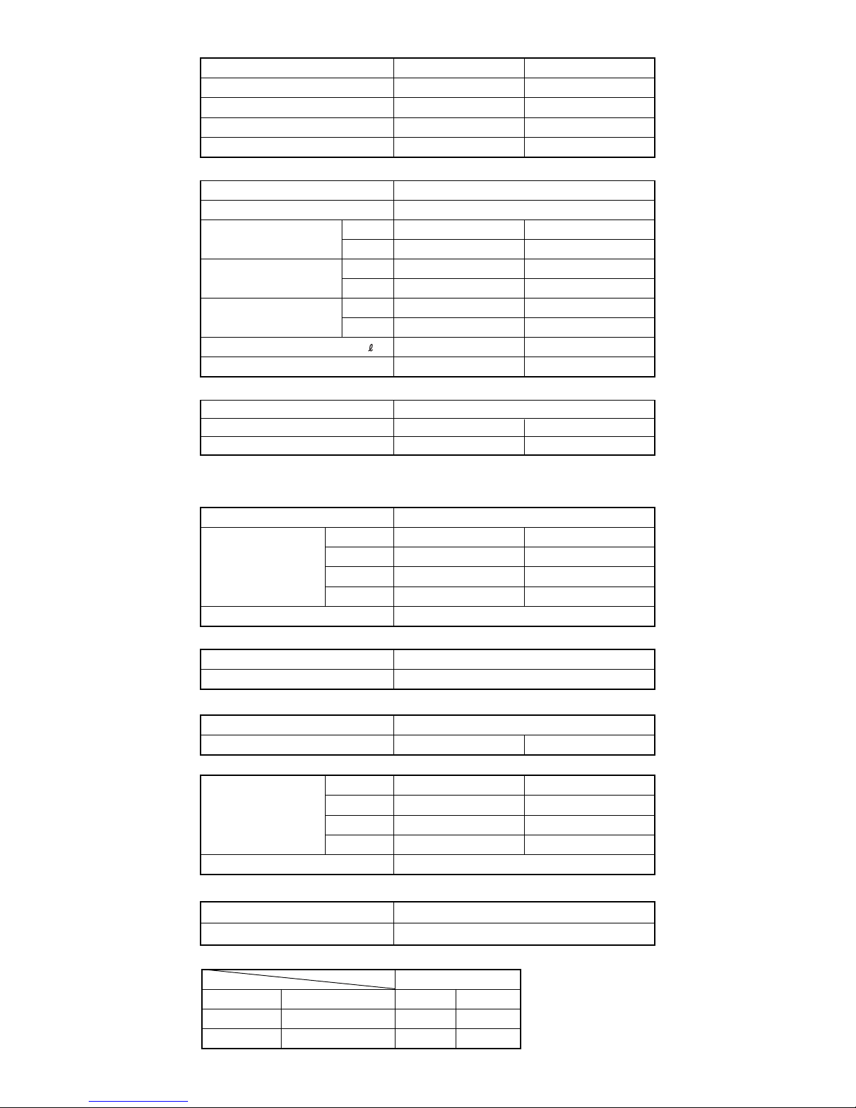
SPECIFICATIONS
TYPE
(COOL&HEAT INVERTER) (COOL&HEAT INVERTER)
INDOOR UNIT
AS*9LSACW AS*12LSACW
OUTDOOR UNIT AO*9LSAC AO*12LSAC
COOLING CAPACITY( ) : Range
(kW)
2.6 (0.5~3.6) 3.5 (0.9~4.2)
HEATING CAPACITY( ) : Range
(kW) 3.6 (0.5~6.0) 4.8 (0.9~6.6)
POWER SOURCE
(V) 230
FREQUENCY
(Hz)
50
RUNNING CURRENT
(A)
COOLING 3.0
3.6
5.8
1.33 (0.25~2.30)0.91 (0.25~1.96)
4.6
HEATING
INPUT WATTS
(kW)
COOLING
0.68 (0.25~1.38) 1.03 (0.25~1.61)
HEATING
EER
(kW/kW)
COOLING 3.82 3.40
3.96 3.61
1.8
HEATING
MOISTURE REMOVAL
1.3
AIR CIRCULATION-Hi
(m3/hr)
C 630 H665
C 630 H700
ELECTRICAL DATA
COMPRESSOR
Note : Always use a vacuum pump to purge the air.
Refrigerant for purging the air is not charged in the outdoor unit at the factory.
DIMENSIONS
TYPE Hermetic type,4 pole, 3 phase , DC brushles motor
DISCRIMINATION 80206680
REFRIGERANT R410A
(g)
(r.p.m.)
(r.p.m.)
950
1100
POWER SOURCE (V) 230
HI-SPEED
MED-SPEED
INDOOR UNIT
LO-SPEED
QUIET
C 1,350 H 1,420
C 1,150 H 1,200
C 950 H 1,000
C 740 H 900
C 1,400 H 1,470
C 1,200 H 1,290
C 1,000 H 1,110
C 820 H 980
OUTDOOR UNIT 830
INDOOR UNIT H x W x D (mm)
H x W x D (mm)
280 x 790 x 230
OUTDOOR UNIT 535 x 780 x 250
FAN MOTOR
(dB)
(dB)
HI-SPEED
MED-SPEED
INDOOR UNIT
LO-SPEED
QUIET
C 42 H 42
OUTDOOR UNIT
NOISE LEVEL
15 m
None
WEIGHTS
INDOOR UNIT
OUTDOOR UNIT
80206680
( /hr)
C 43 H 43
C 37 H 36 C 39 H38
C 31 H 30 C 32 H 33
C 23 H 26 C 26 H 29
C 47 H 49
Note : Noise was measured in accordance with JIS standards, Japan.
GROSS / NET (kg)
GROSS / NET (kg)
12 / 9
35 / 33 37 / 34
MAX PIPE LENGTH
ADDITIONAL REFRIGERANT
THICKNESSES OF ANNEALED COPPER PIPES
Nominal diameter
1/4
3/8
Outer diameter (mm)
6.35
9.52
R410A
0.80
0.80
[ref,] R22
0.80
0.80
Thickness (mm)
01-01
Page 6
SPECIFICATIONS
INDOOR UNIT
H x W x D (mm)
H x W x D (mm)
275 x 790 x 215
OUTDOOR UNIT
540 x 790 x 290
DIMENSIONS
INDOOR UNIT
GROSS / NET (kg)
GROSS / NET (kg)
12 / 9
OUTDOOR UNIT
42 / 3839 / 35
WEIGHT
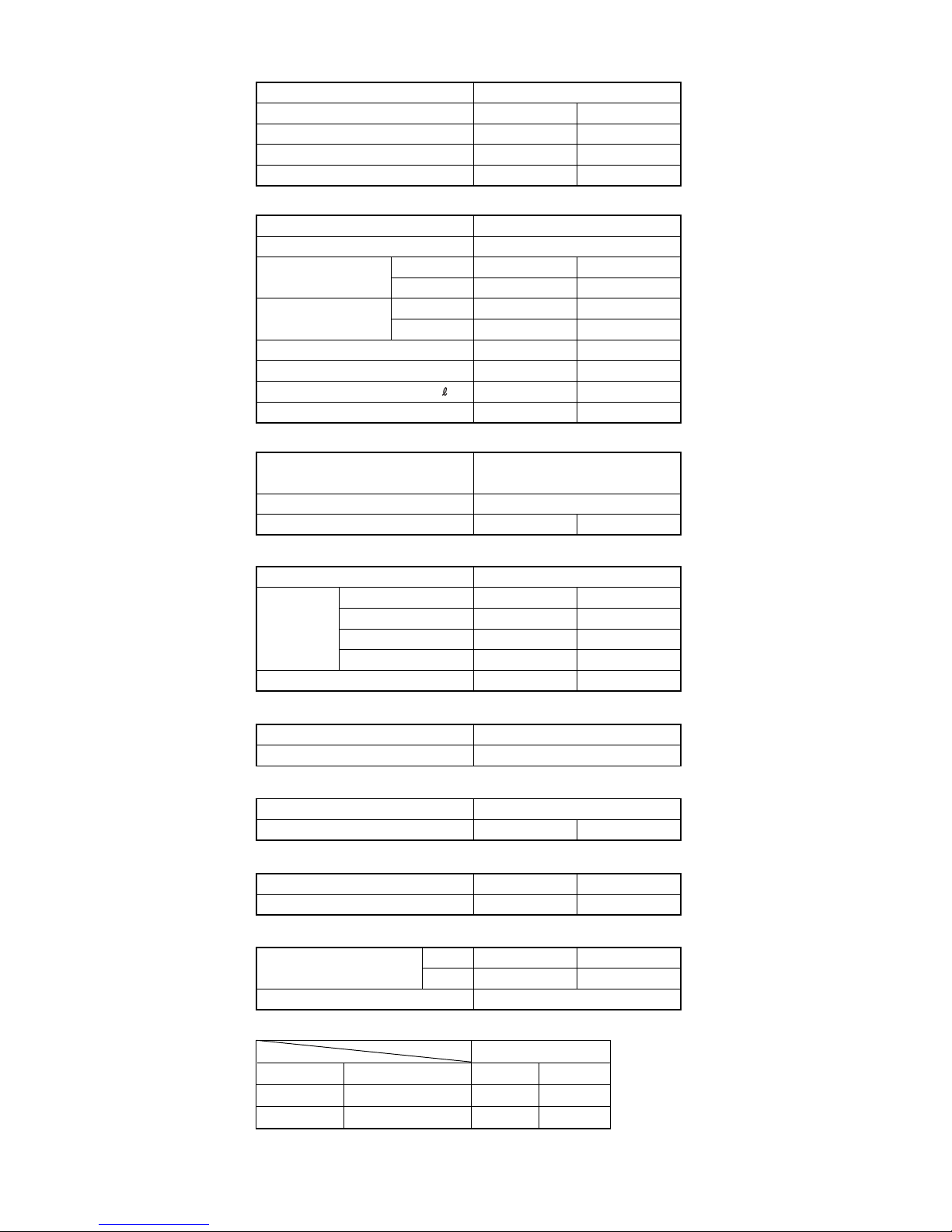
TYPE
COOL & HEAT INVERTER
INDOOR UNIT
AS*12LSBCW
OUTDOOR UNIT
AO*12LFBC
AS*9LSBCW
AO*9LFBC
COOLING CAPACITY
(kW) 3.50
HEATING CAPACITY
(kW)
4.80
POWER SOURCE (V) 230
FREQUENCY (Hz)
50
RUNNING CURRENT
COOLING 4.3
(A)
HEATING
5.6
INPUT WATTS
(kW)
COOLING 0.92
HEATING
1.23
E.E.R.
COOLING
3.80
COP HEATING
3.90
MOISTURE REMOVAL
1.8
AIR CIRCULATION-Hi (m /hr)
3
C 635 H 670C 595 H 645
2.60
3.60
3.0
3.8
0.62
0.82
4.19
4.39
1.3
FAN MOTOR
TYPE
Hermetic type, 4 pole, 3 phase,
DC inverter motor, Rotary
DISCRIMINATION DA 89 X 1F - 20F
REFRIGERANT R410A (g) 1,050950
POWER SOURCE (V) 230
HI-SPEED (r.p.m.) C 1,300 H 1,390
INDOOR
UNIT
MED-SPEED (r.p.m.) C 1,120 H 1,200
LO-SPEED (r.p.m.) C 950 H 1,000
QUIET (r.p.m.) C 700 H 760
C 1,370 H 1,440
C 1,150 H 1,200
C 950 H 1,000
C 700 H 760
OUTDOOR UNIT (r.p.m.) C 830 H 830C 840 H 840
ELECTRICAL DATA
COMPRESSOR
( /hr)
INDOOR UNIT
(dB) C 43 H 43
OUTDOOR UNIT
(dB) C 47 H 49
C 42 H 42
C 47 H 48
NOISE LEVEL
REFRIGERANT (R410A)
Pipe Length
15 m 950 g 1,050 g
FULL CHARGE AMOUNT
20 m 1,050 g 1,150 g
ADDITIONAL REFRIGERANT
20 g / m
(kW/kW)
(kW/kW)
THICKNESSES OF ANNEALED COPPER PIPES
Nominal diameter
1/4
3/8
Outer diameter (mm)
6.35
9.52
R410A
0.80
0.80
[ref,] R22
0.80
0.80
Thickness (mm)
01-02
Page 7
SPECIFICATIONS
INDOOR UNIT
H x W x D (mm)
H x W x D (mm)
275 x 790 x 215
OUTDOOR UNIT
578 x 790 x 300
DIMENSIONS
INDOOR UNIT
GROSS / NET
(kg)
GROSS / NET (kg)
12 / 9
OUTDOOR UNIT
40 / 38
WEIGHT
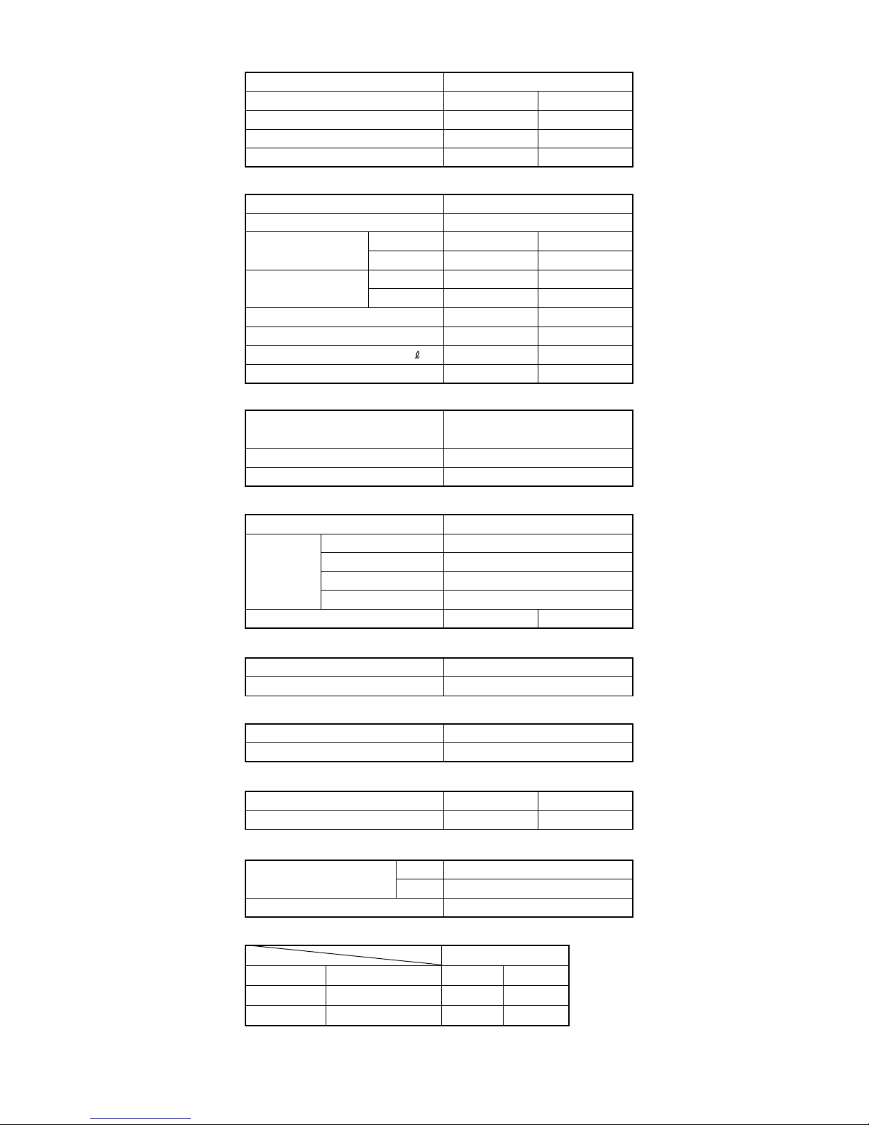
TYPE
COOL & HEAT INVERTER
INDOOR UNIT
AS*18LSBCW
OUTDOOR UNIT
AO*18LFBC
AS*14LSBCW
AO*14LFBC
COOLING CAPACITY
(kW) 5.20
HEATING CAPACITY
(kW)
6.25
POWER SOURCE (V) 230
FREQUENCY (Hz)
50
RUNNING CURRENT
COOLING 7.6
(A)
HEATING
7.6
INPUT WATTS
(kW)
COOLING 1.72
HEATING
1.73
E.E.R.
COOLING
3.02
COP HEATING
3.61
MOISTURE REMOVAL
2.8
AIR CIRCULATION-Hi (m /hr)
3
C 700 H700C 700 H700
4.20
5.60
4.9
6.4
1.11
1.45
3.78
3.86
2.1
FAN MOTOR
TYPE
Hermetic type, 4 pole, 3 phase,
DC inverter motor, Rotary
DISCRIMINATION DA / 30A / F-25F
REFRIGERANT R410A (g) 1,150
POWER SOURCE (V) 230
HI-SPEED (r.p.m.) C 1,480 H 1,480
INDOOR
UNIT
MED-SPEED (r.p.m.) C 1,260 H 1,300
LO-SPEED (r.p.m.) C 1,040 H 1,110
QUIET (r.p.m.) C 850 H 950
OUTDOOR UNIT (r.p.m.) C 860 H 820C 820 H 750
ELECTRICAL DATA
COMPRESSOR
( /hr)
INDOOR UNIT
(dB) C 45 H 43
OUTDOOR UNIT
(dB) C 49 H 49
C 44 H 43
C 48 H 48
NOISE LEVEL
REFRIGERANT (R410A)
PIPE LENGTH
15 m 1,150 g
FULL CHARGE AMOUNT
20 m 1,250 g
ADDITIONAL REFRIGERANT
20 g / m
(kW/kW)
(kW/kW)
THICKNESSES OF ANNEALED COPPER PIPES
Nominal diameter
1/4
1/2
Outer diameter (mm)
6.35
12.7
R410A
0.80
0.80
[ref,] R22
0.80
0.80
Thickness (mm)
01-03
Page 8

2 . DIMENSIONS
R410A
WALL MOUNTED type
INVERTER
Page 9
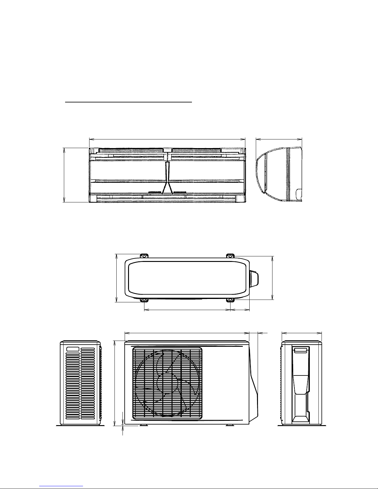
DIMENSIONS
Models : AS*9LSACW / AO*9LSAC
AS*12LSACW / AO*12LSAC
540 120
272
302
780 55
250
535
10
280
790 230
02-01
Page 10
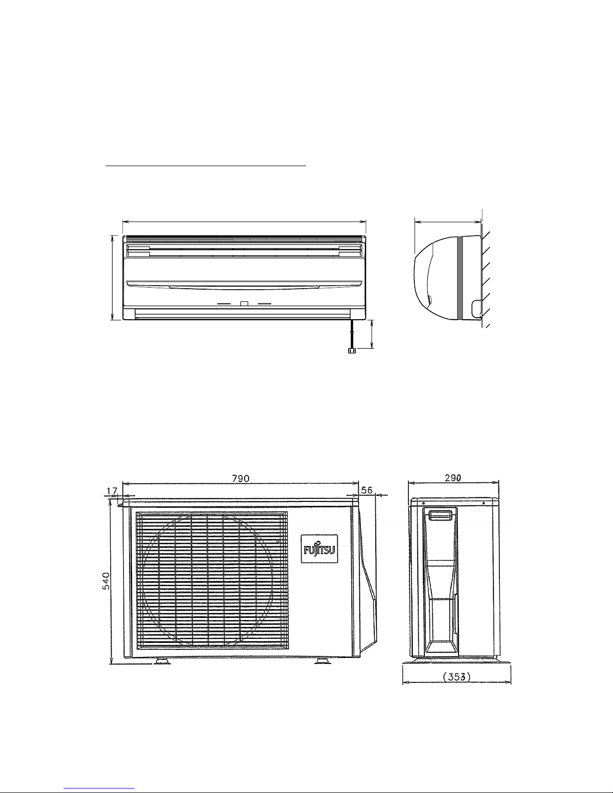
DIMENSIONS
AS*12LSBCW / AO*12LFBC
Models : AS*9LSBCW / AO*9LFBC
(unit : mm)
275
2,000
215
790
02-02
Page 11
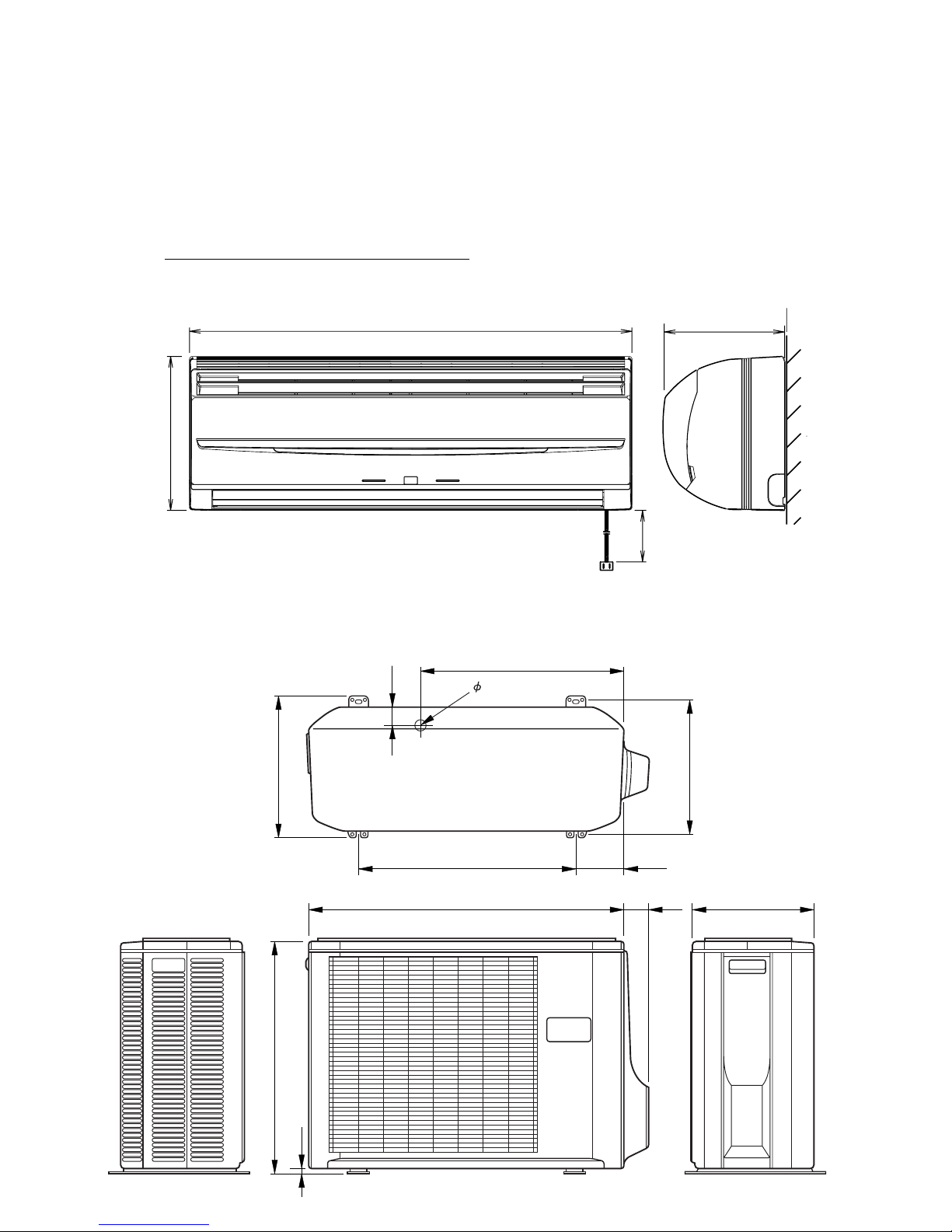
DIMENSIONS
AS*18LSBCW / AO*18LFBC
Models : AS*14LSBCW / AO*14LFBC
(unit : mm)
275
2,000
215
790
347
578
48
10
320
508
540
20
300
125
60
790
02-03
Page 12

3 . REFRIGERANT SYSTEM DIAGRAM
R410A
WALL MOUNTED type
INVERTER
Page 13
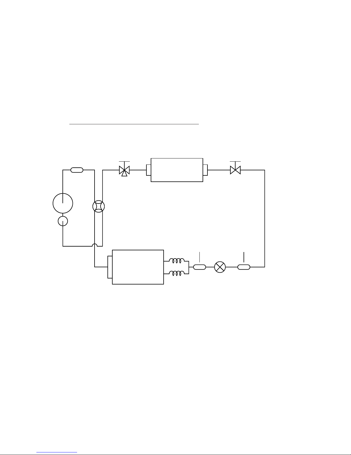
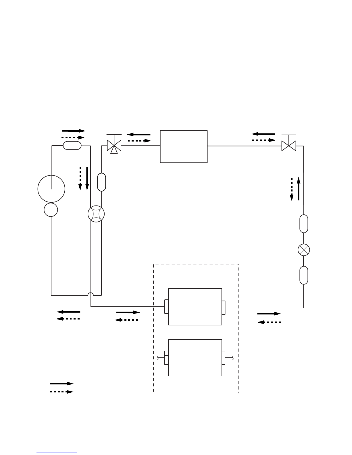
REFRIGERANT SYSTEM DIAGRAM
Models : AS*9LSACW / AO*9LSACW
AS*12LSACW / AO*12LSACW
(2 pass)
(2 pass)
Indoor heat exchanger
Outdoor heat exchanger
Capillary
tube
Pulse motor valve
2way-valve3way-valve
Muffler
Compressor
Accumulator
4way-valve
Strainer Dryer
03-01
Page 14
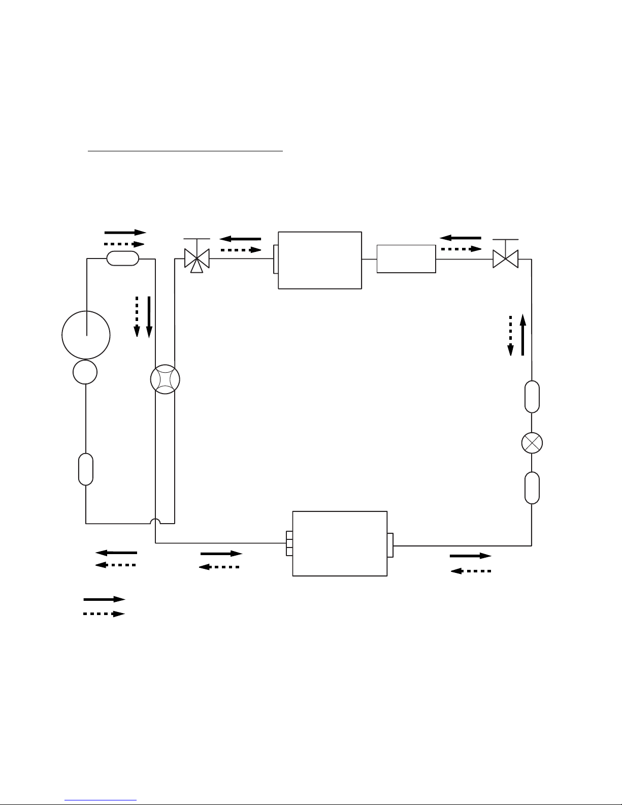
REFRIGERANT SYSTEM DIAGRAM
2-Way
valve
Strainer
Strainer
3-Way
valve
Muffler
Muffler
4-Way valve
Expansion valve
Heat exchanger
( INDOOR )
Heat exchanger
( OUTDOOR )
AOY9LFBC
(2Pass)
AOY12LFBC
(4Pass)
Compressor
Cooling
Heating
AS*12LSBCW / AO*12LFBC
Models : AS*9LSBCW / AO*9LFBC
03-02
Page 15
REFRIGERANT SYSTEM DIAGRAM
2-Way
valve
Strainer
Strainer
Sub-heat
exchanger
( INDOOR )
3-Way
valve
Muffler
4-Way valve
Expansion valve
Heat exchanger
( INDOOR )
Heat exchanger
( OUTDOOR )
Sub-accumulator
Compressor
Cooling
Heating
AS*18LSBCW / AO*18LFBC
Models : AS*14LSBCW / AO*14LFBC
03-03
Page 16

4 . CIRCUIT DIAGRAM
R410A
WALL MOUNTED type
INVERTER
Page 17
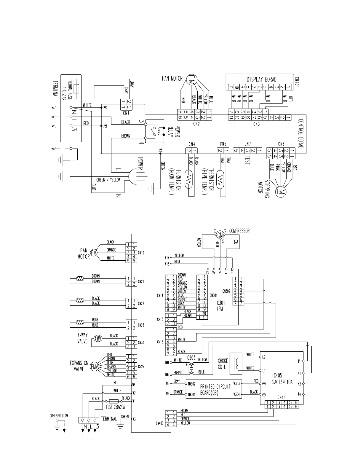
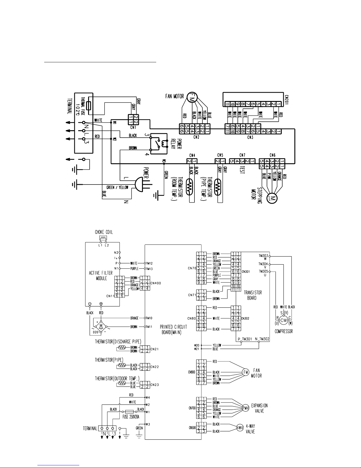
CIRCUIT DIAGRAM
INDOOR UNIT
OUTDOOR UNIT
Models : AS*9LSACW / AO*9LSAC
AS*12LSACW / AO*12LSAC
Controller PCB
Thermistor
(pipe)
Thermistor
(discharge pipe)
Thermistor
(outdoor temp.)
04-01
Page 18
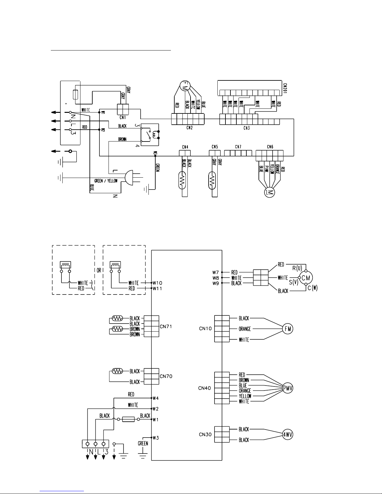
CIRCUIT DIAGRAM
INDOOR UNIT
OUTDOOR UNIT
AS*12LSBCW / AO*12LFBC
Models : AS*9LSBCW / AO*9LFBC
Fan Motor
Stepping
Motor
Thermistor
(room temp.)
Terminal
Terminal
Fuse 250V20A
Reactor Reactor
Fan Motor
Expansion
Valve
4-Way
Valve Assy
PCB (MAIN)
Power
Relay
Compressor
Thermistor
(pipe temp.)
Test
Thermistor (pipe)
Thermistor (Discharge Pipe)
Thermistor (outdoor temp.)
Display Board
Controller PCB
Power
102 C
Thermal Fuse
1
2
3
4
5
6
1
2
3
1
2
3
1
2
3
1
2
3
1
2
3
4
5
1
2
3
4
5
1
2
3
1
2
3
1
2
3
4
1
2
3
4
1
2
3
4
5
6
1
2
3
4
5
1
2
3
4
5
1
2
1
2
1
2
3
4
5
1
2
3
4
5
6
7
1
2
3
4
5
6
1
2
3
4
5
6
1
2
2
1
2
1
3
4
5
6
7
8
9
10
11
1
2
3
4
5
6
7
8
9
10
11
04-02
Page 19
CIRCUIT DIAGRAM
INDOOR UNIT
OUTDOOR UNIT
AS*18LSBCW / AO*18LFBC
Models : AS*14LSBCW / AO*14LFBC
DISPLAY BOARD
CONTROL BOARD
04-03
Page 20

5 . DESCRIPTION OF EACH
CONTROL OPERATION
R410A
WALL MOUNTED type
INVERTER
Page 21
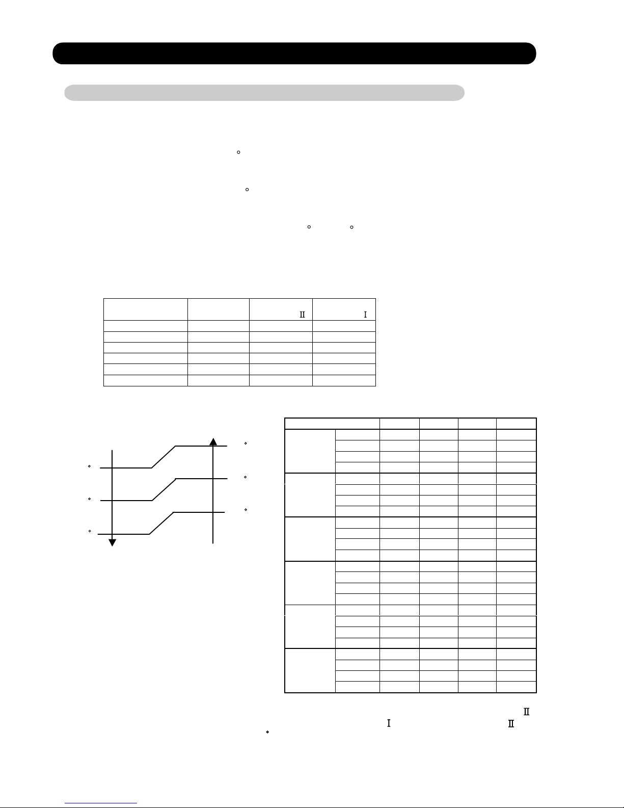
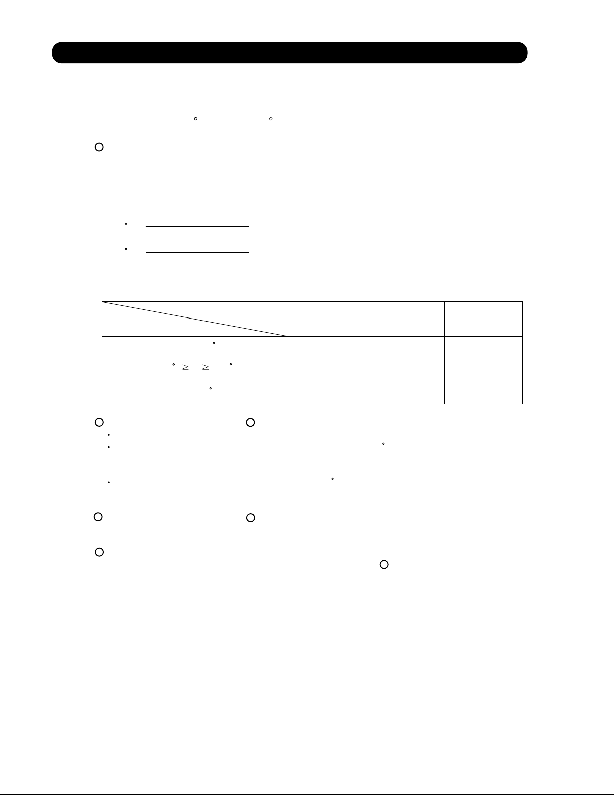
1. COOLING OPERATION
1-1 COOLING CAPACITY CONTROL
A sensor (room temperature thermistor) built in the indoor unit body will usually perceive
difference or variation between a set temperature and present room temperature, and
controls the operation frequency of the compressor.
* If the room temperature is 2 C higher than a set temperature, the compressor operation
frequency will attain to maximum performance.
* If the room temperature is 2.5 C lower than a set temperature, the compressor will be
stopped.
* When the room temperature is between +2 C to -2.5 C of the setting temperature,
the compressor frequency is controlled within the range shown in Table1.
However, the maximum frequency is limited in the range shown in Figure 1 based on the
fan speed mode and the outdoor temperature.
minimum
frequency
maximum
frequency
maximum
frequency
AS*9LSACW 18Hz 60Hz 80Hz
AS*12LSACW 18Hz 80Hz 96Hz
AS*9LSBCW 18Hz 61Hz 80Hz
AS*12LSBCW 18Hz 80Hz 96Hz
AS*14LSBCW 18Hz 70Hz 90Hz
AS*18LSBCW 18Hz 70Hz 90Hz
Outside air Outside air
temperature temperature
36 C
A zone
34 C
32 C
B zone
30 C
21 C
C zone
19 C
D zone
Hi Me Lo Quiet
A zone 80Hz 51Hz 45Hz 33Hz
B zone 80Hz 51Hz 45Hz 33Hz
C zone 80Hz 51Hz 45Hz 33Hz
9LSACW
D zone 51Hz 39Hz 33Hz 27Hz
A zone 96Hz 60Hz 51Hz 33Hz
B zone 96Hz 60Hz 51Hz 33Hz
C zone 80Hz 60Hz 51Hz 33Hz
12LSACW
D zone 51Hz 42Hz 36Hz 27Hz
A zone 80Hz 61Hz 51Hz 33Hz
B zone 80Hz 61Hz 51Hz 33Hz
C zone 80Hz 61Hz 51Hz 33Hz
9LSBCW
D zone 51Hz 42Hz 36Hz 22Hz
A zone 96Hz 61Hz 51Hz 33Hz
B zone 96Hz 61Hz 51Hz 33Hz
C zone 96Hz 61Hz 51Hz 33Hz
12LSBCW
D zone 51Hz 42Hz 36Hz 22Hz
A zone 90Hz 45Hz 42Hz 30Hz
B zone 90Hz 45Hz 42Hz 30Hz
C zone 90Hz 45Hz 42Hz 30Hz
14LSBCW
D zone 49Hz 38Hz 34Hz 24Hz
A zone 90Hz 45Hz 42Hz 30Hz
B zone 90Hz 45Hz 42Hz 30Hz
C zone 90Hz 45Hz 42Hz 30Hz
18LSBCW
D zone 49Hz 38Hz 34Hz 24Hz
( Table 1 : Compressor Frequency Range )
( Fig. 1 : Limit of Maximum Frequency based on Outdoor Temperature )
When the compressor operates for 30 minutes continuously at over the maximum frequency ,
the maximum frequency is changed from Maximum Frequency to Maximum Frequency .
The room temperature is controlled 1 C lower than the setting temperature for 40 minutes
after starting the operation.
After 40 minutes, it is controlled based on the normal setting temperature.
05-01
Page 22
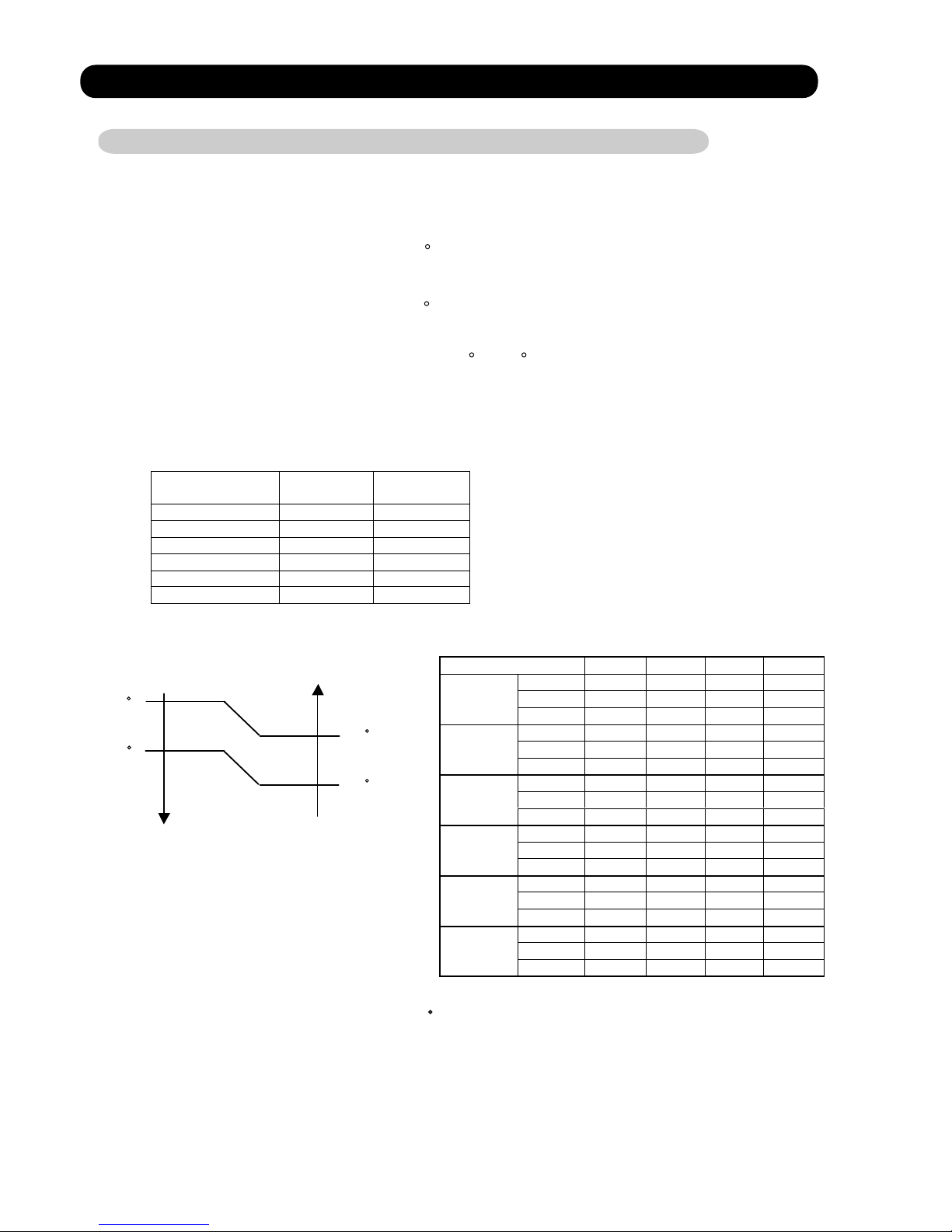
2. HEATING OPERATION
2-1 HEATING CAPACITY CONTROL
A sensor (room temperature thermistor) built in the indoor unit body will usually perceive
difference or variation between a set temperature and present room temperature, and
controls the operation frequency of the compressor.
* If the room temperature is lower by 3 C than a set temperature, the compressor operation
frequency will attain to maximum performance.
* If the room temperature is higher 2.5 C than a set temperatire, the compressor will be
stopped.
minimum
frequency
maximum
frequency
AS*9LSACW 18Hz 130Hz
AS*12LSACW 18Hz 130Hz
AS*9LSBCW 18Hz 130Hz
AS*12LSBCW 18Hz 130Hz
AS*14LSBCW 18Hz 119Hz
AS*18LSBCW 18Hz 119Hz
Outside air Outside air
temperature temperature
19 C
C zone
17 C
14 C
B zone
12 C
A zone
Hi Me Lo Quiet
A zone 130Hz 92Hz 80Hz 68Hz
B zone 130Hz 80Hz 60Hz 54Hz
9LSACW
C zone 96Hz 68Hz 54Hz 51Hz
A zone 130Hz 96Hz 80Hz 68Hz
B zone 130Hz 96Hz 64Hz 57Hz
12LSACW
C zone 96Hz 96Hz 64Hz 54Hz
A zone 130Hz 96Hz 80Hz 68Hz
B zone 130Hz 96Hz 80Hz 54Hz
9LSBCW
C zone 130Hz 96Hz 80Hz 45Hz
A zone 130Hz 96Hz 80Hz 68Hz
B zone 130Hz 96Hz 80Hz 54Hz
12LSBCW
C zone 130Hz 96Hz 80Hz 45Hz
A zone 119Hz 90Hz 70Hz 58Hz
B zone 119Hz 90Hz 70Hz 58Hz
14LSBCW
C zone 119Hz 90Hz 70Hz 58Hz
A zone 119Hz 90Hz 70Hz 58Hz
B zone 119Hz 90Hz 70Hz 58Hz
18LSBCW
C zone 119Hz 90Hz 70Hz 58Hz
* When the room temperature is between +2 C to -3 C of the setting temperature,
the compressor frequency is controlled within the range shown in Table2.
However, the maximum frequency is limited in the range shown in Figure 2 based on the
fan speed mode and the outdoor temperature.
( Table 2 : Compressor Frequency Range )
( Fig.2 : Limit of Maximum Frequency based on Outdoor Temperature )
* The room temperature is controlled 2 C higher than the setting temperature for 60 minutes
after starting the operation.
After 60 minutes, it is controlled based on the normal setting temperature.
05-02
Page 23
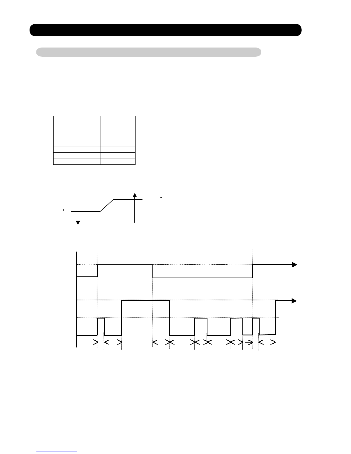
3. DRY OPERATION
3-1 INDOOR UNIT CONTROL
The compressor rotation frequency shall change according to the temperature, set temperature,
and room temperature variation which the room temperature sensor of the indoor unit body has
detected as shown in the Table 3. However, after the compressor is driven, the indoor unit shall
run at operation frequency of 58Hz, for a minute.
Operating
frequency
AS*9LSACW 33Hz
AS*12LSACW 33Hz
AS*9LSBCW 33Hz
AS*12LSBCW 33Hz
AS*14LSBCW 24Hz
AS*18LSBCW 24Hz
room room
temperatu re temperature
compressor ON
Ts+1.5 C
Ts+0.5 C
compressor OFF
Compressor
ON
OFF
Indoor fan
Dry air flow
S-Lo
OFF
10 30 60 180 60 180 60 10 30 (sec)
( Table 3 : Compressor frequency )
( Fig.3 : Compressor Control based on Room Temperature )
( Fig.4 : Indoor Fan Control )
05-03
Page 24
4. AUTO CHANGEOVER OPERATION
When the air conditioner is set to the AUTO mode by remote cintrol, operation starts in the optimum
mode from amoung the HEATING, COOLING, DRY and MONITORING modes. During operation, the
optimum mode is automatically swiched in accordance with temperature changes. The temperature
can be set between 18 C and 30 C in 1 C steps.
.When operation starts, only the indoor and outdoor fans are operated for 1 minute. After 1 minute,
the room temperature and outside air temperature are sensed and the operation mode is
selected in accordance with the table below.
C zone
32 C
B zone
10 C
A zone
( Table.4 Operation mode selection table)
Outside air temperature (TO)
Room temperature(TB)
A zone B zone C zone
TB > TS+ 2 C
Monitoring
Cooling
(automatic dry)
Cooling
(automatic dry)
TS+2 C TB TS-2 C
Monitoring Monitoring Monitoring
TB TS-2 C Heating Heating Monitoring
.When COOING was selected at , the air conditioner operates as follow:
The same operation as COOLING OPERATION of item 1 above is performed.
When the room temperature has remained at (set tempareure -1 C) for 8 minutes, operation is
automatically switched to DRY and the same operation as DRY OPERATION of item 3 above
is performed.
If the room temperature reaches (set temperature+2 C during DRY operation, operation returns to
COOLING operation.
.When HEATING was selected at , the same operation as HEATING OPERATION of item 2
above is performed.
When the compressor was stopped for 6 consecutive minutes by the temperature control function
after the COOLING or HEATING operation mode was selected at above, operation is switched
to MONITORING and the operation mode is selected again.
1
<
1
2
3
1
4
1
( Fig.5 : Outside air temperature zone selection )
05-04
Page 25
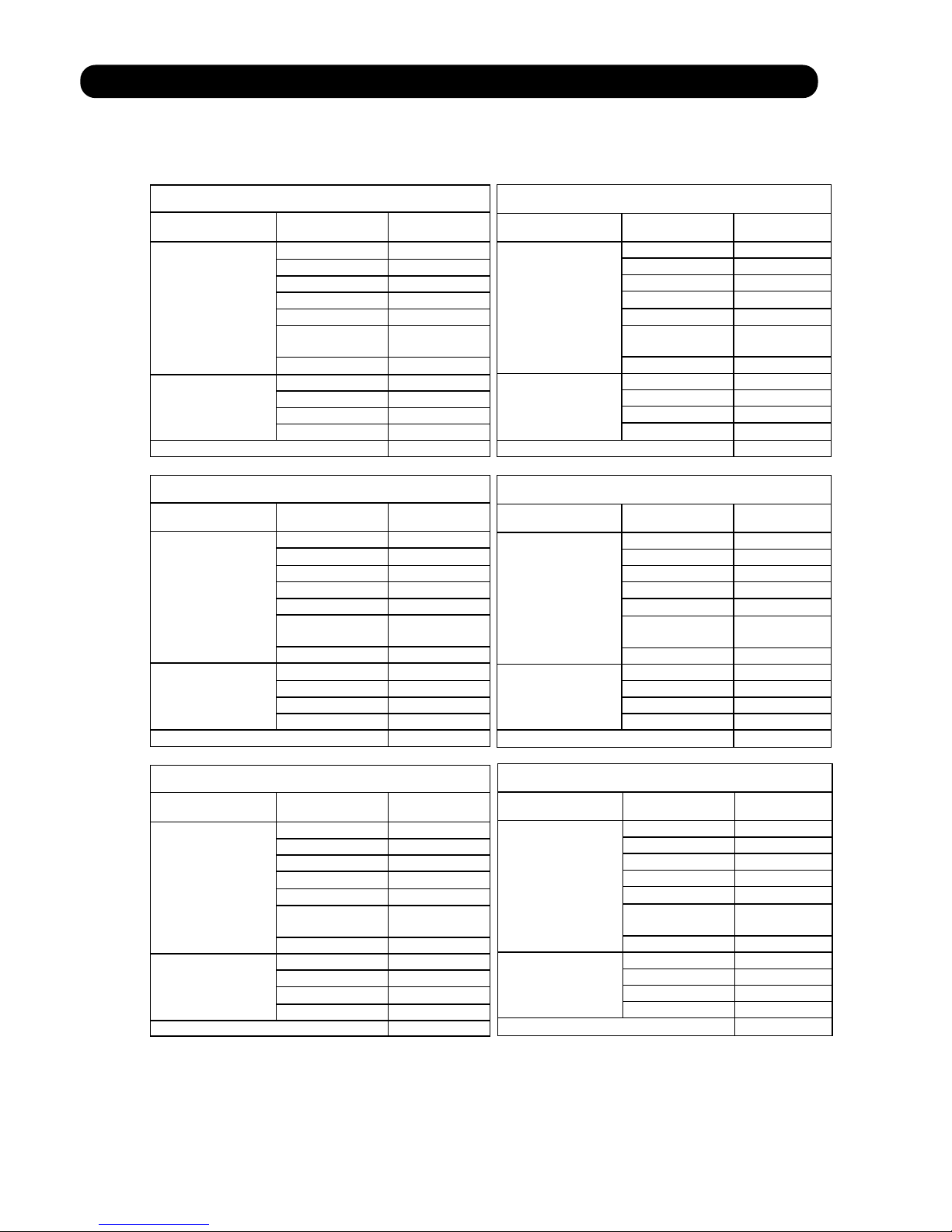
5. INDOOR FAN CONTROL
(1).Fan speed
( Table 5 : Indoor Fan Speed )
AS*9LSACW
Operation mode Air flow mode Speed (rpm)
Hi 1420
Me+ 1370
Me 1200
Lo 1000
Quiet 900
Cool air
prevention
850
Heating
S-Lo 480
Hi 1350
Me 1150
Lo 950
Cooling
Fan
Quiet 740
Dry 740
AS*9LSBCW
Operat ion mode Air flow mode Speed (rpm)
Hi 1390
Me+ 1350
Me 1200
Lo 1000
Quiet 760
Cool air
prevention
760
Heating
S-Lo 480
Hi 1300
Me 1120
Lo 950
Cooling
Fan
Quiet 700
Dry 700
AS*14LSBCW
Operation mode Air flow mode Speed (rpm)
Hi 1480
Me+ 1420
Me 1300
Lo 1110
Quiet 950
Cool air
prevention
850
Heatin g
S-Lo 480
Hi 1480
Me 1260
Lo 1040
Cooling
Fan
Quiet 850
Dry 850
(2).FAN OPERATION
The airflow can be switched in 5 steps such as AUTO, QUIET, LOW, MED, HIGH, while the indoor
fan only runs.
When Fan mode is set at (Auto), it operates on (MED) Fan Speed.
AS*12LSACW
Operation mod e Air flow mode Speed (rpm)
Hi 1470
Me+ 1420
Me 1290
Lo 1110
Quiet 980
Cool air
prevention
850
Heating
S-Lo 480
Hi 1400
Me 1200
Lo 1000
Cooling
Fan
Quiet
820
Dry 820
AS*12LSBCW
Operation mode
Air flow mode Speed (rpm)
Hi 1440
Me+ 1350
Me 1200
Lo 1000
Quiet 760
Cool air
prevention
760
Heating
S-Lo 480
Hi 1370
Me 1150
Lo 950
Cooling
Fan
Quiet
700
Dry 700
AS*18LSBCW
Operation mode Air flow mode Speed (rpm)
Hi 1480
Me+ 1420
Me 1300
Lo 1110
Quiet 950
Cool air
prevention
850
Heating
S-Lo 480
Hi 1480
Me 1260
Lo 1040
Cooling
Fan
Quiet
850
Dry 850
05-05
Page 26

(3).COOLING OPERATION
Switch the airflow [AUTO], and the (Fig.6)
indoor fan motor will run according airflow change - over ( Cooling:AUTO )
to a room temperature, as shown in When the room
Figure 6. temperature rises
On the other hand, if switched in HIGH mode
[HIGH] [QUIET], the indoor motor +2.5
will run at a constant airflow of [COOL] +2.0
operation modes QUIET, LOW, MED, MED mode
HIGH, as shown in Table 5. +1.5
+1.0
LOW mode
When the room
temperature lowers
(Room temperature) D (Setting temperature)
(4).DRY OPERATION
(5).HEATING OPERATION
Switch the airflow [AUTO], and the (Fig.7)
indoor fan motor will run according airflow change - over ( Heating:AUTO)
to a room temperature, as shown in When the room
Figure 7. temperature rises
On the other hand, if switched
LOW mode
[HIGH] [QUIET], the indoor motor -1.0
will run at a constant airflow of [HEAT] -1.5
operation modes QUIET, LOW, MED, MED mode
HIGH, as shown in Table 5. -2.0
-2.5
MED + mode
When the room
temperature lowers
(Room temperature) D (Setting temperature)
(6).COOL AIR PREVENTION CONTROL (Heating mode)
Indoor heat exchanger Indoor heat exchanger
temperature temperature
47 Hi
40 Me+ 40
37
Lo 34
Cool air prevention 32
30
28
S-Lo
Refer to the table 4.
Durring the dry mode operation, the fan speed
setting can not be changed.
The maximum value of the indoor fan speed is set as shown in Figure 8, based on the detected
temperature by the indoor heat exchanger sensor on heating mode.
(Fig.8 : Cool Air Prevention Control)
05-06
Page 27

6. OUTDOOR FAN CONTROL
(1). Outdoor Fan Motor
AC Motor
DC Motor
AS*9/12LSACW
AS*9/12LSBCW
AS*14/18LSBCW
(2). Fan Speed
Cooling Dry Heating
AS*9LSACW 830rpm 830rpm 830rpm
AS*12LSACW 820rpm 820rpm 820rpm
AS*9LSBCW 840rpm 840rpm 840rpm
AS*12LSBCW 830rpm 830rpm 830rpm
Cooling Dry Heating
AS*14LSBCW 860/820/670/500rpm 500rpm 820/750/670/550/450rpm
AS*18LSBCW 860/820/670/500rpm 500rpm 820/750/670/550/450rpm
Following table shows the type of the outdoor fan motor. The control method is different
between AC motor and DC motor.
( Table 6 : Type of Motor )
( Table 7 : AC Motor )
In conjunction with the compressor ON/OFF, the fan speed operates at around the speed
shown above.
*
( Table 8 : DC Motor )
*
The outdoor fan speed changed in the range mentioned avobe depending on the compressor
frequency.
(When the compressor frequency increases, the outdoor fan speed also changes to the higher
speed. When the compressor frequescy decreases, the outdoor fan speed also shanges to the
lower speed.)
*
It runs at 500rpm for 20 seconds after starting up the outdoor fan.
*
After the defrost control is operated on the heating mode, the fan speed keeps at 950rpm
without relating to the compressor frequency.
05-07
Page 28

7. LOUVER CONTROL
(1). VERTICAL LOUVER CONTROL
Each time the button is pressed, the air direction range will change as follow:
Cooling / Dry mode
Heating mode
Fan mode
Use the air direction adjustments within the ranges shown above.
The vertical airflow direction is set automatically as shown, in accordance with the type of operation
selected.
Cooling / Dry mode Horizontal flow
Heating mode Downward flow
When the temperature of the air being blown out is low at the start of heating operation or during
defrosting, the airflow direction temporarily becomes to prevent cold air being blown onto the body.
During use of the Cooling and Dry modes, do not set the Air Flow Direction Louver in the Heating
range ( ) for long period of time, since water vapor many condense near the outlet louvers and
drop of water may drip from the air conditioner. During the Cooling and Dry modes, if the Air Flow
Direction Louvers are left in the hating range for more than 30minutes, they will automatically
return to position .
During Monitor operation in AUTO CHANGEOVER mode, the airflow direction automatically
becomes , and it cannot be adjusted.
Cooling mode / Dry mode / Fan mode( )
Heating mode / Fan mode( )
(Function Range)
(Fig 9: Air Direction Range)
(Operation Range)
(2). SWING OPERATION
When the swing signal is received from the remote controller, the vertical louver starts to
swing.
(Swinging Range)
When the indoor fan is either at S-lo or Stop mode, the swinging operation is interrrupted
and the louver stops at the memorized position.
05-08
Page 29

8. COMPRESSOR CONTROL
(1). OPEARTION FREQUENCY RANGE
The operation frequency of the compressor is different based on the operation mode as
shown in the table 9.
Cooling Heating
Min Max Min Max
Dry
AS*9LSACW 18Hz 80Hz 18Hz 130Hz 33Hz
AS*12LSACW 18Hz 96Hz 18Hz 130Hz 33Hz
AS*9LSBCW 18Hz 80Hz 18Hz 130Hz 33Hz
AS*12LSBCW 18Hz 96Hz 18Hz 130Hz 33Hz
AS*14LSBCW 18Hz 90Hz 18Hz 119Hz 24Hz
AS*18LSBCW 18Hz 90Hz 18Hz 119Hz 24Hz
AS*9LSACW 56Hz 64Hz 74Hz 87Hz 108Hz 120Hz
AS*12LSACW 56Hz 64Hz 74Hz 87Hz 108Hz 120Hz
AS*9LSBCW 56Hz 74Hz 87Hz 97Hz 108Hz 119Hz
AS*12LSBCW 56Hz 74Hz 87Hz 97Hz 108Hz 119Hz
AS*14LSBCW 40Hz 59Hz 72Hz 80Hz 101Hz 110Hz
AS*18LSBCW 40Hz 59Hz 72Hz 80Hz 101Hz 110Hz
AS*9LSACW 80sec 30sec 30sec 30sec 50sec 60sec
AS*12LSACW 80sec 30sec 30sec 30sec 50sec 60sec
AS*9LSBCW 80sec 60sec 60sec 180sec 60sec 60sec
AS*12LSBCW 80sec 60sec 60sec 180sec 60sec 60sec
AS*14LSBCW 60sec 40sec 40sec 60sec 150sec 60sec
AS*18LSBCW 60sec 40sec 40sec 60sec 150sec 60sec
(Table 9 : Compressor Operation Frequency Range)
(2). OPEARTION FREQUENCY CONTROL AT START UP
The compressor frequency soon after the start-up is controlled as shown in the figure 10.
(Fig.10 : Compressor Control at Start-up)
Time
Time Time Time
Time
Time
(Frequency)
(Time)
Frequency
Frequency
Frequency Frequency
Frequency
Frequency
Time Time
Time Time Time Time
Frequency
Frequency
Frequency
Frequency
Frequency
Frequency
05-09
Page 30

9. TIMER OPEARTION CONTROL
(1). OPEARTION FREQUENCY RANGE
The table 10 shows the available timer setting based on the product model.
ON TIMER / OFF TIMER PROGRAM TIMER SLEEP TIMER
AS*9LSACW
AS*12LSACW
AS*9LSBCW
AS*12LSBCW
AS*14LSBCW
AS*18LSBCW
OFF timer : When the clock reaches the set time, the air conditioner will be turned off.
Operation mode
Stop mode
Set time of timer
ON timer : Depending on the difference between the actual room temperature and the set
temperature value, the unit will start operation automatically in order to bring the room
temperature to the desired set temperature value by the timer previously set.
Operation mode
Stop mode
Before the operation start
Set time of timer
At the ON timer when [Heating/Auto time:45 min] [Cooling/dry time:20 min] are reduced, the
indoor fan motor runs with S-Lo for 1 minute, and detects the room temperature. The [Operation
start time] is determined according to the Table 11 as shown below, and the operation is started.
Differential of set temperature and room temperature
Operation Start Time
Heating Cooling Dry
Before 44 minutes 20 C or larger
Before 30 minutes 15 C 20 C
Before 19 minutes 10 C 15 C 10 C or larger 10 C or larger
Before 15 minutes 5 C 10 C 5 C 10 C
Before 10 minutes Less than 10 C Less than 5 C Less than 5 C
The program timer allows the OFF timer and ON timer to be used in combination one time.
Operation mode
Operation will start from the timer setting (either OFF timer or ON timer) whichever is closest
to the clock's current timer setting. The order of operations is indicated by the arrow in the remote
control unit's display.
SLEEP timer operation cannot be combined with ON timer operation.
(Table 10 : Timer Setting)
(Table 11)
(2). PROGRAM TIMER
Stop mode
Stop mode
Stop mode
Operation mode
Operation mode
Set time
Set time Set time Set time
05-10
Page 31

(3). SLEEP TIMER
If the sleep is set, the room temperature is monitored and the operation is stopped automatically.
If the operation mode or the set temperature is change after the sleep timer is set, the operation is
continued according to the changed setting of the sleep timer from that time ON.
Set temperature rises
( Ts : Set temperature )
Stop of operation
Set temperature lowers
( Ts : Set temperature )
Ts
Stop of operation
In the cooling operation mode
When the sleep timer is set, the setting temperature is increased 1 degC.
It increases the setting temperature another 1degC after 1 hour.
After that, the setting temperature is not changed and the operation is stopped at the time
of timer setting.
Ts
+1.0
+2.0
Set
60min
In the heating operation mode
When the sleep timer is set, the setting temperature is decreased 1 degC.
It decreases the setting temperature another 1degC every 30 minutes.
Upon lowering 4degC, the setting temperature is not changed and the operation stops at
the time of timer setting.
-4.0
-3.0
-2.0
-1.0
Set
30min
30min
30min
05-11
Page 32

10. ELECTRONIC EXPANSION VALVE CONTROL
The most proper opening of the electronic expansion valve is calculated and controlled under the
present operating condition based on the following values.
The compressor frequency, the temperatures detected by the discharge temperature sensor, the
indoor heat exchanger sensor, the outdoor heat exchanger sensor, and the outdoor temperature
sensor.
The pulse range of the electronic expansion valve control is between 60 to 480 pulses.
The expansion valve is set at 480 pulses after 110 seconds of stopping compressor.
At the time of supplying the power to the outdoor unit, the initialization of the electronic
expansion valve is operated (528 pulses are input to the closing direction).
11. TEST OPERATION CONTROL
Under the condition where the air conditioner runs, press the test operation button of the remote
control, and the test operation control mode will appear. During test running, the operation lamp
and timer lamp of the air conditioner body twinkle simultaneously. Set the test operation mode,
and the compressor will continue to run regardless of whether the room temperature sensor detects.
The compressor won't enter operation status for 2 minutes and 20 seconds after the compressor is
stopped, even if any operation is given.
At the time when the air conditioner is switched from the cooling mode to heating mode, the
compressor is stopped, and the four-way valve is switched in 2 minutes and 20 seconds later after
the compressor stopped.
When the power was interrupted by a power failure, etc. during operation, the operation contents
at that time are memorized and when power is recovered, operation is automatically started with
the memorized operation contents.
When the power is interrupted and recovered during timer operation, since the timer operation time
is shifted by the time the power was interrupted, an alarm is given by blinking (7 sec ON/2 sec OFF)
the indoor unit body timer lamp.
[Operation contents memorized when the power is interrupted]
Operation mode
Set temperature
Set air flow
Timer mode and timer time
Set air flow Direction
Swing
The test operation mode is released if 60 minutes have passed after setting up the test operation.
12. PREVENT TO RESTART FOR 3 MINUTES ( 3 MINUTES ST )
13. FOUR-WAY VALVE EXTENSION SELECT
14. AUTO RESTART
05-12
Page 33

15. MANUAL AUTO OPERATION (Indoor unit body operation)
If MANUAL AUTO Button is set, the operation is controlled as shown in Table 12.
If the remote control is lost or battery power dissipated, this function will work without the remote
control.
OPERATION MODE Auto changeover
FAN CONT. MODE Auto
TIMER MODE Continuous
SETTING TEMP. 24 C
SETTING LOUVER Standard
SWING OFF
When the outdoor heat exchanger temperature is lower than temperature and the heating operation has
been stopped for 30 minutes, power is applied to the compressor and the compressor is heated.
(By heating the compressor, warm air is quickly discharged when operation is started.)
When operation was started, and when the outdoor temperature rises to temperature or greater, preheating
is ended.
AS*9LSACW
AS*12LSACW
AS*9LSBCW
AS*12LSBCW
AS*14LSBCW
AS*18LSBCW
AS*9LSACW
900rpm 36Hz
AS*12LSACW
900rpm 36Hz
AS*9LSBCW
900rpm 36Hz
AS*12LSBCW
900rpm 36Hz
AS*14LSBCW
900rpm 24Hz
AS*18LSBCW
900rpm 24Hz
(Table 12)
(No timer setting available)
16. COMPRESSOR PREHEATING
(Table 13 : Preheating Operation / Release Temperature)
Temperature
Temperature
5 C
5 C
5 C
5 C
5 C
5 C
7 C
7 C
7 C
7 C
7 C
7 C
17. COIL DRY OPERATION CONTROL
The coil-dry operation functions by pressing Coil Dry operation button on the remote controller.
The coil-dry operation is consisted of 3 cycles of [Fan operation 3 minutes / Heating operation
2 minutes], and Fan operates for 3 minutes at last before ending the air conditioner operation.
(It takes 18 minutes to complete the coil-dry operation.)
Following table indicates the indoor unit setting on the coil-dry operation.
(Table 14 : Coil-dry Operating Functions)
Indoor Fan Speed
Compressor
Frequency
Louver
Position
Main Unit
Indocation
Coil-dry indication : ON
Other indication : OFF
05-13
Page 34

18. DEFROST OPERATION CONTROL
(1). CONDITION OF STARTING THE DEFROST OPERATION
The defrost operation starts when the outdoor heat exchanger temperature sensor detects
the temperature lower than the values shown in Table 15.
(Table 15 : Condition of starting Defrost Operation)
AS*9LSACW
AS*12LSACW
AS*9LSBCW
AS*12LSBCW
AS*14LSBCW
AS*18LSBCW
AS*9LSACW
AS*12LSACW
AS*9LSBCW
AS*12LSBCW
AS*14LSBCW
AS*18LSBCW
AS*9LSACW
AS*12LSACW
AS*9LSBCW
AS*12LSBCW
AS*14LSBCW
AS*18LSBCW
1 time defrosting
after starting
operation
ST
Defrosting after 2
time upon starting
operation
ST
Compressor operating time
Less than 20 minutes 20 to 60 minutes
60 minutes to 4 hours
After 4 hours
Does not operate
- 9 C
- 9 C
- 9 C
- 9 C
- 9 C
- 9 C
- 5 C
- 5 C
- 5 C
- 5 C
- 5 C
- 5 C
- 3 C
- 3 C
- 3 C
- 3 C
- 3 C
- 3 C
Less than 35 minutes
35 minutes to
4 hours
Does not operate
Compressor operating time
After 4 hours
- 3 C
- 3 C
- 3 C
- 3 C
- 3 C
- 3 C
- 6 C
- 6 C
- 6 C
- 6 C
- 6 C
- 6 C
(2). CONDITION OF THE DEFROST OPERATION COMPLETION
Defrost operation is released when the conditions become as shown in Table 16.
(Table 16 : Defrost Release Condition)
Release Condition
Outdoor heat exchanger temperature sensor value is higher than 10degC or
Compressor operation time has passed 15 minutes.
Outdoor heat exchanger temperature sensor value is higher than 10degC or
Compressor operation time has passed 15 minutes.
Outdoor heat exchanger temperature sensor value is higher than 16degC or
Compressor operation time has passed 15 minutes.
Outdoor heat exchanger temperature sensor value is higher than 16degC or
Compressor operation time has passed 15 minutes.
Outdoor heat exchanger temperature sensor value is higher than 10degC or
Compressor operation time has passed 15 minutes.
Outdoor heat exchanger temperature sensor value is higher than 10degC or
Compressor operation time has passed 15 minutes.
05-14
Page 35

Defrost Flow Chart
The defrosting shall proceed by the integrating operation time and outdoor heat exchanger
temperature as follows.
(Not defrosted for 10 minutes)
(In case of 1st defrost) (In case of 2nd and later defrost)
Compressor OFF
Outdoor fan motor OFF
30 sec later four - way valve OFF
36 sec later compressor ON
Heating operation start : Compressor ON
Compressor integrating
operation:
Over 20 minutes to
below 60 minutes
Compressor integrating
operation:
Over 60 minutes to
below 240 minutes
Compressor integrating
operation:
Over 240 minutes
Compressor integrating
operation:
Over 35 minutes to
below 240 minutes
Compressor integrating
operation:
Over 240 minutes
Outdoor heat exchanger
temperature:
Below - 9 C
Outdoor heat exchanger
temperature:
Outdoor heat exchanger
temperature:
Outdoor heat exchanger
temperature:
Outdoor heat exchanger
temperature:
Defrost start
Defrost Indicator:
[Operation lamp]
7 sec ON / 2 sec OFF
Outdoor heat exchanger temperature:
Over 10 C / 16 C
or
Compressor ON time:
Over 15 minutes
Defrost end
Below - 5 C
Below - 3 C
Below - 6 C
Below - 3 C
05-15
Page 36

19. OFF DEFROST OPEARTION CONTROL
(1). OFF DEFROST OPERATION CONDITION
When operation stops in the [Heating operation] mode, if frost is adhered to the outdoor unit heat
exchanger, the defrost operation will proceed automatically. In this time, if indoor unit operation
lamp flashes slowly (7 sec ON / 2 sec OFF), the outdoor unit will allow the heat exchanger to defrost,
and then stop.
In heating operation, the outdoor heat exchanger temperature is less than - 4 C, and compressor
operation integrating time lasts for more than 30 minutes.
AS*9LSACW
AS*12LSACW
AS*9LSBCW
AS*12LSBCW
AS*14LSBCW
AS*18LSBCW
OFF Defrost Flow Chart
Heating operation stop
Outdoor heat exchanger temperature:
Below - 4 C
and
Compressor integrating operation:
Over 30 minutes
Defrost start
Defrost Indicater:
[Operation lamp]
Outdoor heat exchanger temperature:
Over 10 C / 16 C
or
Compressor ON time:
Over 15 minutes
Defrost end
(2). OFF DEFROST END CONDITION
Release Condition
Outdoor heat exchanger temperature sensor value is higher than 10degC or
Compressor operation time has passed 15 minutes.
Outdoor heat exchanger temperature sensor value is higher than 10degC or
Compressor operation time has passed 15 minutes.
Outdoor heat exchanger temperature sensor value is higher than 16degC or
Compressor operation time has passed 15 minutes.
Outdoor heat exchanger temperature sensor value is higher than 16degC or
Compressor operation time has passed 15 minutes.
Outdoor heat exchanger temperature sensor value is higher than 10degC or
Compressor operation time has passed 15 minutes.
Outdoor heat exchanger temperature sensor value is higher than 10degC or
Compressor operation time has passed 15 minutes.
7 sec ON / 2 sec OFF
05-16
Page 37

20. VARIOUS PROTECTIONS
(1). DISCHARGE GAS TEMPERATURE OVERRISE PREVENSION CONTROL
The discharge gas thermosensor (discharge thermistor : Outdoor side) will detect discharge gas
temperature.
AS*9LSACW 104 C 101 C 110 C
AS*12LSACW 104 C 101 C 110 C
AS*9LSBCW 104 C 101 C 110 C
AS*12LSBCW 104 C 101 C 110 C
AS*14LSBCW 104 C 101 C 110 C
AS*18LSBCW 104 C 101 C 110 C
AS*9LSACW AS*12LSACW AS*9LSBC W AS*12LSBCW AS*14LSBCW AS*18LSBCW
OT (Control / Release)
6.5A / 6.0A
17 C
8.0A / 7.5A
12 C
8.0A / 7.5A
8.0A / 7.5A
6.5A / 6.0A
8.0A / 7.5A
8.5A / 8.0A
9.5A / 9.0A
6.5A / 6.0A
8.0A / 7.5A
8.0A / 7.5A
8.0A / 7.5A
6.5A / 6.0A
8.0A / 7.5A
8.5A / 8.0A
9.5A / 9.0A
7.0A / 6.5A
9.0A / 8.5A
10.5A / 10.0A
12.0A / 11.5A
7.0A / 6.5A
9.0A / 8.5A
10.5A / 10.0A
12.0A / 11.5A
AS*9LSACW AS*12LSACW AS*9LSBCW AS*12LSBCW AS*14LSBCW AS*18LSBCW
3.5A / 3.0A
46 C
4.0A / 3.5A
40 C
5.5A / 5.0A
4.0A / 3.5A
5.0A / 4.5A
6.5A / 6.0A
3.5A / 3.0A
4.0A / 3.5A
5.5A / 5.0A
4.0A / 3.5A
5.0A / 4.5A
6.5A / 6.0A
4.5A / 4.0A
6.0A / 5.5A
8.5A / 8.0A
4.5A / 4.0A
6.0A / 5.5A
8.5A / 8.0A
When the discharge temperature becomes higher than Temperature ,the compressor frequency
is decreased 20 Hz, and it continues to decrease the frequency for 20 Hz every 120 seconds until
the temperature becomes lower than Temperature .
When the discharge temperature becomes lower than Temperature ,the control of the control of the
compressor frequency is released.
When the discharge temperature becomes higher than Temperature ,the compressor is stopped
and the indoor unit LED starts blinking.
(Table 17 : Discharge Temperature Over Rise Prevension Control / Release Temperature)
Temperature
Temperature
Temperature
(2). CURRENT RELEASE CONTROL
The compressor frequency is controlled so that the outdoor unit input current does not exceeds
the current limit velue that was set up with the outdoor temperature.
The compressor frequency returns to the designated frequency of the indoor unit at the time
when the frequency becomes lower than the release value.
(Table 18 : Current Release Operation Value / Release Value)
[ Heating ]
[ Cooling / Dry ]
OT : Outdoor Temperature
OT (Control / Release) OT (Control / Release)
OT (Control / Release)
OT (Control / Release)
OT (Control / Release)
OT : Outdoor Temperature
OT (Control / Release) OT (Control / Release)
OT (Control / Release)
OT (Control / Release) OT (Control / Release)
OT (Control / Release)
5 C
17 C
12 C
5 C
17 C
12 C
5 C
17 C
12 C
5 C
17 C
12 C
5 C
17 C
12 C
5 C
46 C
40 C
46 C
40 C
46 C
40 C
46 C
40 C
46 C
40 C
05-17
Page 38

(3). ANTIFREEZING CONTROL (Cooling and Dry mode)
The compressor frequency is decrease on cooling & dry mode when the indoor heat exchanger
temperature sensor detects the temperature lower than Temperature .
Then, the anti-freezing control is released when it becomes higher than Temperature .
AS*9LSACW
AS*12LSACW
AS*9LSBCW
AS*12LSBCW
AS*14LSBCW
AS*18LSBCW
(Table 19 : Anti-freezing Protection Operation / Release Temperature)
TemperatureTemperature
4 C
4 C
4 C
4 C
4 C
4 C
7 C
7 C
7 C
7 C
7 C
7 C
(4). COOLING PRESSURE OVERRISE PROTECTION
(Table 20 : Cooling Pressure Over Rise Protection Function Temperature)
When the outdoor unit heat exchange sensor temperature rises to temperature or greater, the
compressor is stopped and trouble display is performed.
AS*9LSACW 65 C
AS*12LSACW 65 C
AS*9LSBCW 67 C
AS*12LSBCW 67 C
AS*14LSBCW 65 C
AS*18LSBCW 65 C
Temperature
AS*9LSACW
AS*12LSACW
AS*9LSBCW
AS*12LSBCW
AS*14LSBCW
AS*18LSBCW
Indoor heat exchange
temperature
[ AS*9/12LSBCW ]
52Hz or greater 51Hz
26 51Hz
18 25Hz OFF
AS*9LSACW 52 C 48 C 54 C 50 C
AS*12LSACW 52 C 48 C 54 C 50 C
(5). HIGH TEMPERATURE RELEASE CONTROL ( HEATING MODE )
On heating mode, the compressor frequency is controlled as following based on the
detection value of the indoor heat exchanger temperature sensor.
(The control system is different depending on the product model)
Control system
(Fig 11 : Heating Overload Protection Control)
[ Control System ]
Temperature
Temperature
Refer to below
The frequency increase every
60 seconds gradually.
It returns to the normal operation
after 5 minutes.
Fan Hi
Other than Hi
Temp
Temp Temp
Temp
Compressor Operation
Frequency down evry 60 seconds
05-18
Page 39

Indoor heat exchange
temperature
[ AS*9/12LSBCW ]
52Hz or greater 51Hz
26 51Hz
18 25Hz OFF
AS*9LSACW 52 C 48 C 54 C 50 C
AS*12LSACW 52 C 48 C 54 C 50 C
[ Control System ]
Temperature
Temperature
Refer to below
The frequency increase every
60 seconds gradually.
It returns to the normal operation
after 5 minutes.
Fan Hi
Other than Hi
Temp
Temp Temp
Temp
Compressor Operation
Frequency down evry 60 seconds
[ AS*9/12LSBCW ]
[ AS*14/18LSBCW ]
46Hz or greater 45Hz
39Hz or greater 38Hz
39 45Hz
38Hz
26 38Hz 25Hz
19 29Hz 18Hz
18 25Hz OFF
OFF
AS*9LSBCW 55 C 53 C 52 C 50 C
AS*12LSBCW 55 C 53 C 52 C 50 C
AS*14LSBCW 55 C 53 C 52 C 50 C
AS*18LSBCW 55 C 53 C 52 C 50 C
Indoor heat exchange
temperature
[ Control System ]
Temperature
Temperature
Refer to below
Temperature
Temperature
The compressor frequency is
precisely controlled so that
it does not exceeds Temperature .
It returns to the normal operation
Compressor Operation
18Hz
30
Frequency down every 120 seconds
Frequency down every 120 seconds
Temp
Temp Temp
Temp
05-19
Page 40

6 . REFRIGERANT CAUTION -R410A-
R410A
WALL MOUNTED type
INVERTER
Page 41

1. R410A TOOLS
Gauge manifold . . . . . . . . . . . . . . . . . . . . . (Fig.4-1)
Since the normal pressure is high, the connection pipe size
is also different.
Charge hose . . . . . . . . . . . . . . . . . . . . . . . (Fig.4-2)
Refrigerant cylinder . . . . . . . . . . . . . . . . . (Fig.4-3)
Confirm the refrigerant type before charging. Always
charge liquid-phase refrigerant.
Electronic balance for refrigerant
charging . . . . . . . . . . . . . . . . . . . . . . . . . . . (Fig.4-4)
Electronic balance is recommended as in the case of
R410A.
Vacuum pump with adapter to prevent
reverse flow . . . . . . . . . . . . . . . . . . . . . . . .(Fig.4-5)
Conventional pump can be used.
Vacuum holder . . . . . . . . . . . . . . . . . . . . . (Fig.4-6)
Conventional pump can be used if adapter for preventing
vacuum pump oil from flowing back is used.
Gas leakage tester . . . . . . . . . . . . . . . . . . (Fig.4-7)
Exclusive for HFC
Refrigerant cleaner . . . . . . . . . . . . . . . . . . (Fig.4-8)
Brown paint as designated by the ARI, USA
Flare tool . . . . . . . . . . . . . . . . . . . . . . . . . . (Fig.4-9)
Torque wrench . . . . . . . . . . . . . . . . . . . . (Fig.4-10)
Refrigerant recovering
equipment (Collector) . . . . . . . . . . . . . . (Fig.4-11)
The type which can be used for any refrigerant is available
Nitrogen cylinder . . . . . . . . . . . . . . . . . . . (Fig.4-12)
This prevents an oxide film from forming in the pipe silveralloy brazing work by turning the air out of the pipe and
preventing the inside combustion.
Safety charger . . . . . . . . . . . . . . . . . . . . . (Fig.4-13)
It is always compulsory to change the liquid, because
R410A is a mixed refrigerant and there is some fear that a
mixing ratio changes. In order to avoid the refrigerant from
returning to the compressor in a liquid state, the refrigerant
can be charged instead of giving a load to the compressor
with a safety charger.
Control valve . . . . . . . . . . . . . . . . . . . . . . (Fig.4-14)
The control valve prevents the refrigerant from spouting
when it is removed, as the charging hose side and the service port side are possible to open and close at the same
time.
Thermistor vacuum gauge . . . . . . . . . . . (Fig.4-15)
To remove moisture from the refrigerating cycle completely, it is necessary to perform appropriate vacuum drying.
For that reason, vacuum conditions can be confirmed certainly.
Vacuum valve . . . . . . . . . . . . . . . . . . . . . (Fig.4-16)
This valve builts in a check valve, and it is easily possible
to vacuum a refrigerating cycle or check for degree of vacuum with it.
TOOLS AND EQUIPMENT (R410A)
Refrigerant cylinder
Gauge Manifold
R410A
R22, R407C
High
pressure
gauge
Compond
gauge
Port size
-0.1 5.3
Mpa
-0.1 3.8
Mpa
1/2UNF
5/16"
-0.1 3.5
Mpa
-0.1 1.7
Mpa
7/16UNF
1/4"
*
1
Charge hose
R410A
R22, R407C
Normal
pressure
Port size
5.1 Mpa
27.4 Mpa
1/2UNF
3.4 Mpa
17.2 Mpa
7/16UNF
*
2
Breaking
pressure
This air conditioner used R410A.
For installation and servicing, it is necessary to prepare the
tools and machines that are different from the previous
refrigerant.
Mark shows the exclusive use for R410A.
The specification of the gauge is different due
to higher pressure.
The size of connection pipe is also different to
prevent mis-use.
The shape of flare is different for
high pressure condition.
06-01
Page 42

2. PRECAUTION FOR INSTALLATION
Precaution for installation
Selection of pipe
Pipe thickness
Outer diameter Thickness
1/4” (6.35mm) 0.8 mm
3/8” (9.52mm) 0.8 mm
1/2”(12.7mm) 0.8 mm
Be sure to use this pipe thickness and over
for countermeasure against higher
pressure.
Flare and flare nuts
Diameter 1/4”(6.35mm) 3/8”(9.52mm) 1/2”(12.7mm)
Refrigerant
R410A
R22
/R407C
R410A R410A
A 9.1 9.0 13.2 13.0 16.6
16.2
B 13 12 20 15 13 20
C 12 11 16 12.5 19 16
Nut width 17 22 26 24
Always use the flare nut that is packed
with the product.
Do not use existing (for R22) pipes
• Be sure to use new pipes when replacing
conventional (R22) model with HFC
(R407C, R410A) model.
• If you use existing pipes, it may cause
resolution of compressor oil by remaining
mineral oil.
R22
/R407C
R22
/R407C
06-02
Page 43

Be careful not to mix moisture and
contamination into the pipe
Moisture and contamination
in the pipe is a cause of
trouble.
Air purge
Always use a
vacuum pump
to purge air.
Refrigerant charge
Do it always from the liquid phase
side.
Don't charge from the gas phase side.
Compressor oil is changed
Be careful to handle synthetic oil, since it
resolves easily by moisture and
contamination.
Don't mix new synthetic oil and mineral oil.
It may cause trouble.
We developed new synthetic oil, since HFC
refrigerant doesn't dissolve in mineral (for R22)oil.
06-03
Page 44

3. PRECAUTION FOR SERVICING
Feature 1 Refrigerant oil is different from before.
Refrigerant oil for
New Refrigerant
Synthetic oil
Ether
Esther
Different point from
previous one
Previously it was
mineral oil.
Absorbent character
is high.
Contamination occurs
when mixed withe other
kind of oil.
Use the gauge manifold and charge hose
for New Refrigerant(HFC), which shall
be segregated from those of R22.
Attach the stop valve on the vacuum pump
and avoid the oil from reverse frow.
It is necessary to use the vacuum pump
which can obtain the high vacuum condition.
Precaution on Tools
Feature 2 New Refrigerant has Approx 1.6 times higher pressure than previous refrigerant.
R410A
High Pressure
Different point from
previous one
Diameter of Service port
has been changed from
1/4 Flare to 5/16 Flare.
It requires the gauge manifold and charge
hose exclusively for R410A.
It requires the flare tool and torque wrench
that satisfies New JIS standard.
Precaution on Tools
R410A R22
1.6 times of R22.
JIS standard of flare
process It became lager
To keep thethickness of
copper tube.
(1/4,3/3=more than 0.8mm)
Previous flare tool + flare adapter can be used as well.
06-04
Page 45

4. NEW REFRIGERANT R410A
What is HFC ?
Phase-out schedule of HCFC
according to Montreal protocol
1996 20102000 2004 2015 2020 2030
60
40
20
100
(Year)
(%)
80
(HCFC consumption of 1989) +
(CFC consumption of 1989) x 2.8%
65%
35%
10%
0.5%
started control
only service use
total abolition
100% =
0
*
06-05
Page 46

Page 47

Page 48

OIL
• Use new synthetic oils such as ester because HFC series refrigerant has less solubility with mineral oils
conventionally used for R22.
• As these new synthetic oils are easily influenced by moisture and dusts, they must be treated more care-
fully than the conventional lubricating oils.
CAUTION
For installation/servicing, take more precautions than the case of conventional refrigerants to avoid moisture
and dusts entering the refrigerant circuit. Also, for storing parts, more precautions must be taken.
2, 3-WAY VALVE
• Review material O-ring, valve core seal for securing suitability with oil.
CAUTION
Check if the valve is suitable for the refrigerant (model) when replacing.
CAUTION
Check if the compressor is suitable for the refrigerant (model) when replacing. Complete welding within 15
minutes after opening the cap when replacing.
COMPRESSOR
• Use better grade of material for sliding parts for securing good lubrication of sliding part as HFC
refrigerant does not contain chloride.
• Review insulating materials
• Increase pressure resistance strength
CAUTION
During storage, due care must be taken so that foreign matters such as dust and water do not enter.
HEAT EXCHANGER
• Review the water,contaminants controlling level
• Use thinner tube to increase pressure Increase capacity for resistance strength (only outdoor unit)
improving performance
CAUTION
Check if the valve is suitable for the refrigerant (model) when replacing.
4-WAY VALVE
• Review materials
5. DEFFERENCE FROM CONVENTIONAL MODEL (R22) AND PRECAUTIONS
06-08
Page 49

7 . TROUBLE SHOOTING
R410A
WALL MOUNTED type
INVERTER
1. When the unit does not operate at all (Operation lamp and Timer lamp do not light up)
2. Self Diagnosis Function (Either Operation lamp or Timer lamp is blinking)
* How to operate the self-diagnosis function
* Self- diagnosis table and Check points
3. Trouble shooting method
* Serial signal check
* IPM protection check
* Active filter error check
* Refrigeration cycle diagnosis
Page 50

Does not operate at all (Operation Lamp and Timer Lamp do not light up)
[Check Point]
(1) Is the input power voltage from the exclusive circuit AC outlet normal?
(2) Is the AC plug inserted to the AC outlet securely and not loose?
(3) Check if each connector is inserted securely.
[Checking Flow Chart]
Is AC input voltage from AC outlet normal ?
Is AC voltage between VA 1 normal?
Is DC voltage between terminal of C5 normal?
Is DC voltage between terminals of C7 and C12
Is DC voltage between terminal 1 & 2 of IC6 normal?
YES (AC220/230V)
YES (AC220/230V)
YES (AC220/230V)
Is DC voltage between terminals of C9
YES (C7:DC20V)
(C12:DC13.5 1V)
YES (DC12 14V)
Terminal board temperature
fuse is blown or CN1 is loose
(IC2, T1 or IC3 defective)
IC4 defective
YES (DC15V)
Is DC voltage between terminals 3 & 4 of IC7 normal?
YES (Pulse wave of DC5Vp-p)
IC7 defective
(F1, VA1 defective)
Input power supply failure
Controller PCB defective
NO
NO
NO
NO
NO
NO
NO
Switching power circuit
Switching power circuit
Switching power circuit
(F2, D1, R1 defective)
07-01
Page 51

SELF-DIAGNOSIS FUNCTION
This function memorizes the self-diagnosis function (lamp display) in the in door control P.C.Board
when trouble occurs.
(The memory contents are not destroyed even when the power cord is unplugged from the AC outlet.)
The self-diagnosis function (lamp display) can also be switched between major classification display
and minor classification display and precise diagnosis can be made.
Self-diagnosis function [lamp display] (memory reading)
(1) When error occurs, it is indicated by blinking [Operation lamp (Red)] and [Timer lamp (Green)].
(2) Upon pulling out and inserting the AC plug, the starts to operates from remote control.
(At this state, a normal operation indication is performed.)
(3) By pressing [TEST] button of remote control, [Large Division Error Indication] is indicated only
during
[3 minutes ST].
(3 minutes ST : 2 minutes 20 seconds from the timing AC plug is ON)
[Lamp display]
3 minutes delay
Turn off Operating Large Div. Error Indication Normal indication after
3min.ST
Indication
AC Plug ON Start operation Input TEST signal
(4) By pressing [TEST] button of remote control while [Large Division Error Indication], it switches
to
[Small Division Error Indication].
(5) Every time [TEST] button of remote control is pressed, it switches between [Large Division Error
Indication] and [Small Division Error Indication] alternately.
How to erase Memory
(1) While [Large Division Error Indication] or [Small Division Error Indication] is ON by the
self-diagnosis function, the memorized contents can be erased by pressing [Forced Auto
Button] on the main unit.
(Indoor unit buzzer beeps 3 seconds.)
07-02
Page 52

Self - diagnosis function and Checking points
Large Division Error
Indication
Small Division Error
Indication
Operation
Timer
Large Div.
Contents
Opera
tion
Timer
Small Div. Contents
(Protection)
Diagnosis Method
0.1
sec.
blinki
ng
0.5 sec
2 times
Serial reverse transfer
error at starting up
operation
At the start up, the indoor unit does not receive the signal for 10 consecutive seconds from the time when the
power relay was ON. > Permanent stop after 30 seconds.
[Diagnosis Point]
- Check the indoor/outdoor cable connection (in order). If the cable wiring is not abnormal, measure the
voltage of the outdoor unit terminals and diagnose the defective location.
(Refer to the after mentioned [Serial Signal Diagnosis] for the voltage measuring method and diagnosis
method.)
0.1
sec.
blinki
ng
0.5 sec
3 times
Serial reverse transfer
error during the
operation
When the indoor unit does not receive the signal for 10 consecutive seconds during the operation > Permanent
stop after 30 seconds.
[Diagnosis Point]
- Check the indoor/outdoor cable connection (in order). If the cable wiring is not abnormal, measure the
voltage of the outdoor unit terminals and diagnose the defective location.
(Refer to the after mentioned [Serial Signal Diagnosis] for the voltage measuring method and diagnosis
method.)
0.1
sec.
blinki
ng
0.5 sec
4 times
Serial forward transfer
error at starting up
operation
The outdoor unit does not receive the signal for 10 consecutive seconds from the time when the power relay was
ON. > Outdoor unit stops.
[Diagnosis Point]
- Check the indoor/outdoor cable connection (in order). If the cable wiring is not abnormal, measure the
voltage of the outdoor unit terminals and diagnose the defective location.
(Refer to the after mentioned [Serial Signal Diagnosis] for the voltage measuring method and diagnosis
method.)
ON 1 sec.
blinking
Transmission
Error
0.1
sec.
blinki
ng
0.5 sec
5 times
Serial forward transfer
error during the
operation
When the outdoor unit does not receive the signal for 10 consecutive seconds during the operation >
Outdoor unit stops.
[Diagnosis Point]
- Check the indoor/outdoor cable connection (in order). If the cable wiring is not abnormal, measure the
voltage of the outdoor unit terminals and diagnose the defective location.
(Refer to the after mentioned [Serial Signal Diagnosis] for the voltage measuring method and diagnosis
method.)
07-03
Page 53

0.1
sec.
blinki
ng
0.5 sec
2 times
Room temperature
thermistor defective
The room temperature thermistor detected a abnormal temperature when the power was turned on.
> Remote control does not operate.
[Diagnosis Point]
- Check Thermistor resistance value (Refer to “Thermistor characteristics table”).
- Controller PCB defective.
0.5 sec
2 times
0.1 sec.
blinking
Indoor Unit
Thermistor
Error
0.1
sec.
blinki
ng
0.5 sec
3 times
Indoor Heat Exchanger
Thermistor Error
The detection value of the indoor heat exchanger thermistor is either open or shorted when the power is ON.
> Remote control does not operate.
[Diagnosis Point]
- Check Thermistor resistance value (Refer to “Thermistor characteristics table”).
- Controller PCB defective.
0.1
sec.
blinki
ng
0.5 sec
2 times
Discharge Thermistor
Error
The detection value of the discharge thermistor is either open or shorted
> Compressor, Outdoor Fan : OFF (It automatically releases when the normal value is detected.)
[Diagnosis Point]
- Check Thermistor resistance value (Refer to “Thermistor characteristics table”).
- Controller PCB defective.
0.1
sec.
blinki
ng
0.5 sec
3 times
Outdoor Heat Exchanger
Thermistor Error
The detection value of the outdoor heat exchanger thermistor is open.
> Compressor, Outdoor Fan : OFF (It automatically releases when the normal value is detected.)
[Diagnosis Point]
- Check Thermistor resistance value (Refer to “Thermistor characteristics table”).
- Controller PCB defective
0.5 sec
3 times
0.1 sec.
blinking
Outdoor Unit
Thermistor
Error
0.1
sec.
blinki
ng
0.5 sec
4 times
Outdoor Temperature
Thermistor Error
The detection value of the outdoor temperature thermistor is either open or shorted
> Compressor, Outdoor Fan : OFF (It automatically releases when the normal value is detected.)
[Diagnosis Point]
- Check Thermistor resistance value (Refer to “Thermistor characteristics table”).
- Controller PCB defective.
0.5 sec
4 times
0.1 sec.
blinking
Indoor Unit
Controller
Error
0.1
sec.
blinki
ng
0.5 sec
2 times
Forced Auto Switch
Error
Forced Auto Switch becomes ON for 10 consecutive seconds.
> It indicates the error but the operation continues.
[Diagnosis Point]
- Check if Forced Auto Switch is kept pressed.
- Forced Auto Switch defective.
- Controller PCB defective.
07-04
Page 54

0.1
sec.
blinki
ng
0.5 sec
3 times
Main Relay Error
After 2 minutes 20 seconds of stopping operation, the signal from outdoor unit is received even though the main
relay is OFF.
> Main Relay OFF continues (Outdoor Unit OFF Command)
[Diagnosis Point]
- Main Relay defective
- Controller PCB defective.
0.1
sec.
blinki
ng
0.5 sec
4 times
Power Supply
Frequency Detection
Error
The power supply frequency can not be recognized after 4 seconds of power ON.
> Permanent stop.
[Diagnosis Point]
- Controller PCB defective.
0.1
sec.
blinki
ng
0.5 sec
2 times
IPM Protection
Abnormal current value of IPM is detected > Permanent stop.
[Diagnosis Point]
- Heat radiation is blocked (Inlet/Outlet)
- Check if Outdoor Fan is defective (does not rotate).
- Controller PCB defective (Refer to after mentioned “IPM diagnosis”)
- Refrigeration cycle defective (Refer to after mentioned “Refrigeration cycle diagnosis”).
0.1
sec.
blinki
ng
0.5 sec
3 times
CT Error
The current value during the operation after 1 minute from starting up the compressor is 0 A.
> Permanent stop.
[Diagnosis Point]
- Check if CT wire is open.
- Controller PCB defective.
0.1
sec.
blinki
ng
0.5 sec
5 times
Compressor Location
Error
The compressor speed does not synchronize with the control signal. (Including start up failure of the compressor)
> Permanent stop.
[Diagnosis Point]
- Check if 2 way valve or 3 way valve is left open.
- Check the compressor (Winding resistance value, Loose lead wire).
- Refrigeration cycle defective (Refer to after mentioned “Refrigerant cycle diagnosis”).
0.5 sec
5 times
0.1 sec.
blinking
Outdoor Unit
Controller
Error
0.1
sec.
blinki
ng
0.5 sec
6 times
Outdoor Fan Error
(DC Motor)
Either the outdoor fan motor abnormal current or location error was detected.
> Permanent stop.
[Diagnosis Point]
- Fan motor connector loose/ defective contact.
- Fan motor defective.
- Controller PCB defective.
07-05
Page 55

0.1
sec.
blinki
ng
0.5 sec
2 times
Indoor Fan Lock Error
The indoor fan speed is 0 rpm after 56 seconds from starting operation or from the time the fan mode was
changed. > Operation stops. (It releases by sending the operation stop signal from the remote controller.)
[Diagnosis Point]
- Fan motor connector loose/ defective contact.
- Fan motor defective.
- Controller PCB defective.
0.5 sec
6 times
0.1 sec.
blinking
Indoor Fan
Motor Error
0.1
sec.
blinki
ng
0.5 sec
3 times
Indoor Fan Speed Error
The indoor fan speed is 1/3 of the target frequency after 56 seconds from starting operation or from the time the
fan mode was changed. > Operation stops. (It releases by sending the operation stop signal from the remote
controller.)
[Diagnosis Point]
- Fan motor connector loose/ defective contact.
- Fan motor defective.
- Controller PCB defective.
0.1
sec.
blinki
ng
0.5 sec
2 times
Discharge Temperature
Error
The discharge temperature error is activated. > Permanent stop.
[Diagnosis Poijnt]
- Check if 2 way valve or 3 way valve is left open.
- Heat radiation is blocked (Inlet/Outlet)
- Check if Outdoor Fan is defective (does not rotate).
- Refrigeration cycle defective (Refer to after mentioned “Refrigerant cycle diagnosis”).
0.5 sec
7 times
0.1 sec.
blinking
Refrigerant
Cycle Error
0.1
sec.
blinki
ng
0.5 sec
3 times
Excessive High Pressure
Protection on Cooling
Excessive high pressure protection on cooling mode has been activated.
> Compressor, Outdoor Fan : OFF (It releases after 3 minute ST)
[Diagnosis Point]
- Heat radiation is blocked (Inlet/Outlet)
- Check if Outdoor Fan is defective (does not rotate).
- Refrigeration cycle defective (Refer to after mentioned “Refrigerant cycle diagnosis”).
0.1
sec.
blinki
ng
0.5 sec
2 times
Active Filter Error
(Permanent Stop)
Output voltage error of Active filter is detected. > Permanent stop.
[Diagnosis Point]
- Check the wiring connection (Connector is loose/open, Choke coil)
- Controller PCB defective (Refer to after mentioned “Active Filter diagnosis”)
0.5 sec
8 times
0.1 sec.
blinking
Other Error
0.1
sec.
blinki
ng
0.5 sec
3 times
Active Filter Error
Active filter error or instantaneous cut off error is detected.
> Compressor, Outdoor Fan : OFF
[Diagnosis Point]
- Check the wiring connection (Connector is loose/open, Choke coil)
- Controller PCB defective (Refer to after mentioned “Active Filter diagnosis”)
<CAUTION> Even if the unit is normal, it may detect error depending on the power supply voltage condition.
07-06
Page 56

0.1
sec.
blinki
ng
4 times
PFC Circuit Error
Excessive voltage of DC voltage on PFC circuit in Inverter PCB is detected, or the excessive current in the circuit
is detected. > Permanent stop.
[Diagnosis Point]
- Controller PCB defective (Refer to after mentioned “PFC circuit diagnosis”).
07-07
Page 57

Serial Signal Diagnosis
[Check Point] Check and find out if the cause is at Indoor unit or Outdoor unit.
* Remove the side cover of Outdoor unit for testing the Outdoor unit connection terminals with a meter.
* Turn on the power and press [TEST] button of Remote control.
[Checking Flow Chart]
[Check Indoor Unit]
CAUTION: Do not touch the terminals or electrical components to avoid electric shock.
Is AC220V/AC230V applied to the terminals N-L on
the Outdoor unit terminal plate?
Connecting cable wiring defect
In correct wiring
Main PCB defective
NO
YES
Measure the voltage between terminals N-3 on the
Outdoor unit terminal plate.
Refer to Fig.1 for Measuring Method.
Judge the result based on Table 1.
L
N
+
Measurement method 1
Diode
(Dielectric voltage : Higher than 600V)
Range DC
(Normal : DC30 60V)
Red
Black
White
+
Range DC
(Normal : DC30 60V)
Red
Black
White
L
N
Fig.1 Selial Signal Measuring Method
Measurement 1 Measurement 2 Indoor unit Outdoor unit
Defective point
voltage value voltage value trouble display operation
0 5V
30 60 V Display No operation Indoor unit control PCB defective
30 60V 0 5V Display No operation Outdoor unit fuse open (input)
Inverter defective
Table 1: Judgement table
L
N
Outdoor unit terminal
plate
Power supply
AC220V/230V
Black
White
Serial
signals
-
-
3
3
3
Red
Measurement method 2
07-08
Page 58

IPM Protection
[Checking Points]
Check the following points and locae the cause in the outdoor unit.
[Cause]
(1) Compressor failure
(2) Refrigeration cycle failure
(3) PC Board defective
(4) IPM defective
(5) Incorrect wiring
[First step]
Measure the DC voltage at terminals (between Electrolytic Capacitor and discharge resistance)
in the Inverter Controller Assy, and make sure it is lower than DC5V.
Check point (1)
Open the Inverter Controller Assy
Yes(Normal)
Go to Check point (2)
and check if there is abnormal points.
No(Abnormal)
Incorrect wiring > Correct and recheck
Parts touched > Correct and recheck
Parts broken > Change the broken part
Check point (2)
Turn on the power and press TEST button
Yes(Rotating)
Go to Check point (3)
on Remote Control.
No(Not rotating)
IPM or PCB defective > Replace PCB
Is the outdoor fan rotating?
Check point (3)
Operate the unit for certain time and
Yes(Operating)
The unit is normal.
check if the compressor is operating.
No(Not operating)
IPM or PCB defective > Replace PCB
Recheck
Operate the unit for certain time and Yes(Operating) > Check completed
check if the compressor is operating. No(Not operating) > Return to the start
If it is higher than 5V, wait until the discharging is over.
07-09
Page 59

Active Filter Failure
[Checking points]
Check the following points and locae the cause in the outdoor unit.
[Cause]
(1) Incorrect wiring
(2) Active Filter Module defective
(3) PC Board defective
(4) DC voltage detectiion circuit defective
[First Step]
Measure the DC voltage at terminals (between Electrolytic Capacitor and discharge resistance)
in the Inverter Controller Assy, and make sure it is lower than DC5V.
If it is higher than 5V, wait until the discharging is over.
Open the Inverter Controller Assy
and check if there is abnormal points.
Incorrect wiring > Correct and recheck
(Incorrect wiring, Parts touched, Parts broken)
Parts touched > Correct and recheck
Parts broken > Change the broken part
Turn on the power and press TEST button
on Remote Control.
Is the outdoor fan rotating?
Operate the unit for certain time and
measure the terminal voltage of the
The unit is normal.
discharge resistance.
Is the DC voltage between 350 to 425V?
Recheck
Operate the unit for certain time and Yes(Operating) > Check completed
check if the compressor is operating. No(Not operating) > Return to the start
Check point (1)
Yes(Normal)
Go to Check point (2)
No(Abnormal)
Check point (2)
Yes(Rotating)
Go to Check point (3)
No(Not rotating)
Check point (3)
Yes(Within range)
No(Out of range)
ACTPM or PCB defective > Replace Main PCB
ACTPM or PCB defective > Replace ACTPM or
Main PCB.
(Replace only ACTPM if Main PCB was replaced
at Check point (2).)
07-10
Page 60

Trouble Shooting of Refrigerant Cycle
[Diagnosis Table for Defective Component]
: Item of most possible cause
IPM Protection
Compressor
Location error
Discharge
Temperature Error
Cooling High
Pressure
Protection
Refrigerant leak
Compressor failure(*)
EEV failure (*)
Thermistor failure (*)
(*) Trouble Shooting Method
(1) Checking method of the compressor failure
Insert the AC plug and start up the cooling operation. Input Test operation signal and check if the
compressor operates.
If it does not operate, measure the resistance value of compressor windings between U-V, V-W,
W-U.
If any of the resistance value between U-V, V-W, W-U is not same as others, the compressor is
defective.
Compressor Failure
NORMAL
ASY9/12LSACW Compressor Case Temperature at 25degC: 0.512 ohm
ASY9/12LSBCW Compressor Case Temperature at 20degC: 0.701 ohm
ASY14/18LSBCW Compressor Case Temperature at 25degC: 0.730 ohm
(The above resistance value is a typical value. There is some distribution. As it also changes by the
compressor temperature, the measured value may be much different from the above table when
measured right after stopping operation.)
(2) Checking method of EEV failure
- Insert the AC plug and start up the operation. Check if the EEV operates just before compressor is turned
on. (Touch EEV by hand and check it.)
If it does not operate, check if the coil or connector of EEV is removed or loose.
If it operates, check the discharge thermistor / outdoor heat exchanger thermistor / indoor heat
exchanger thermistor. (Refer to (3) for checking method.)
(3) Checking method of Thermistor
- Check each thermistor if it is removed or the connector is loose.
If there is no problem, remove the connector of the thermistor from the PCB and check the resistance
value (refer to the thermitor characteristics table).
07-11
Page 61

8 . APPENDING DATA
R410A
WALL MOUNTED type
INVERTER
1. Jumper setting of Indoor unit and Outdoor unit
2. Outdoor unit Pressure Value and Total Electric Current Curve
3. Thermistor Resistance Values
Page 62

JP (Jumper) Setting
[Indoor Unit]
AS*9/12LSACW
AS*9/12LSBCW
AS*14/18LSBCW
Remote control custom code
When multiple number of indoor units are installed in the same room, erroneous receipt of the signal can
be avoided by setting up the remote control custom code separately.
To set up the remote control custom code, always set up the same code on both indoor unit PCB and
remote control PCB.
(When the indoor unit PCB is changed to Code B, it can not receive the signal unless remote control PCB
is also changed to Code B.)
Indoor Unit Remote Control
JM1(JP)
D4 (Diode)
Code A (Default)
Code B
Auto Restart
It is possible to disengage Auto Restart function if it is not needed.
Indoor Unit
JM2 (JP)
With Auto Restart function
(Default)
YES
Without Auto Restart
function
NO
[Outdoor Unit]
AO*9/12LSAC
JP
JM101 JM102 JM103 JM104 JM105 JM106 JM107
Normal Preheat
NO
NO NO
NO
NO
YES
NO
9LSAC
Higher Preheat
NO NO NO
YES
NO NO NO
Normal Preheat
NO
YES
NO NO NO NO NO
12LSAC
Higher Preheat
NO
NO
NO NO NO NO NO
AO*9/12LFBC
JP
JM500
Normal Preheat YES
Higher Preheat NO
AO*14/18LFBC
JP
JM101 JM102 JM103 JM104 JM105 JM106 JM107
Normal Preheat
NO YES
NO NO NO NO NO
14LSBC
Higher Preheat
NO
NO
NO NO NO NO NO
Normal Preheat
NO NO NO NO NO
YES
NO
18LSBC
Higher Preheat
NO
NO NO
YES
NO NO NO
- it is possible to select the higher or standard level of preheating function.
- When it is set up at the higher level of preheat, the magnetic noise of the compressor becomes higher.
08-01
AR-JE (LSAC)
X
X
D3 (Diode)
AR-NJ (LSBC)
X
*
*
Page 63

Outdoor Unit Low Pressure Value and Outdoor Total Electric Current Curve (Cooling)
Model Name : AS*9LSACW, AS*12LSACW
[Condition]
Ambient
temperature
Indoor / Outdoor - Same temperature
Refrigerant
amount
Standard amount
Piping
length
7.5m (Height difference 1m)
Power
voltage
50Hz - 230V
Operation
condition
TEST mode (Cooling), Hi Fan, Horizontal direction, Front air flow
Measuring
method
Caution
Start operation with the condition of the Indoor Unit air filter clean.
[Constant Frequency Operation Method (Test mode)]
1. Operate on Colling mode, and press TEST button of remote control.
2. Operate continuously for 30 minutes. (After 60 minutes of operation, Test mode is released automatically.)
(1) Indoor/Outdoor Temperature - Outdoor Low Pressure Curve
AS*9LSACW series AS*12LSACW
(2) Indoor/Outdoor Temperature - Outdoor Total Electric Current Curve
AS*9LSACW series AS*12LSACW
Measure the low pressure with the pressure meter at the service valve. Measure the outdoor
0.7
0.8
0.9
1
1.1
1.2
15 20 25 30 35
In/outdoor ambient temparature (degC)
Low-pressure opf outdoor unit MPaG
RH50%
RH60%
RH70%
3.5
4
4.5
5
15 20 25 30 35
In/outdoor ambient temparature (degC)
Outdoor total electric current A
RH50%
RH60%
RH70%
0.8
0.9
1
1.1
1.2
1.3
1.4
15 20 25 30 35
In/outdoor ambient temparature (degC)
Low-pressure of outdoor unit MPaG
RH 50%
RH 60%
RH 70%
2.00
2.20
2.40
2.60
2.80
15 20 25 30 35
In/outdoor ambient temparature (degC)
Outdoor total electric current A
RH 50%
RH 60%
RH 70%
unit overall current with the current clamp meter at Power Cable.
08-02
Page 64

Outdoor Unit High Pressure Value and Outdoor Total Electric Current Curve (Heating)
Model Name : AS*9LSACW, AS*12LSACW
[Condition]
Ambient
temperature
Indoor 15 - 23degC, Outdoor 2 - 12degC
Refrigerant
amount
Standard amount
Piping 7.5m (Height difference 1m)
Power
voltage
50Hz - 230V
Operation
condition
TEST mode (Heating), Hi Fan, Lower direction, Front air flow
Measuring
method
Caution
Start operation with the condition of the Indoor Unit air filter clean.
[Constant Frequency Operation Method (Test mode)]
1. Operate on Heating mode, and press TEST button of remote control.
2. Operate continuously for 30 minutes. (After 60 minutes of operation, Test mode is released automatically.)
(1) Indoor/Outdoor Temperature - Outdoor High Pressure Curve
AS*9LSACW series
AS*12LSACW
(2) Indoor/Outdoor Temperature - Outdoor Total Electric Current Curve
AS*9LSACW series AS*12LSACW
outdoor unit overall current with the current clamp meter at Power Cable.
2
2.2
2.4
2.6
2.8
3
3.2
3.4
0 5 10 15
outdoor ambient temparature C
High-pressure of outdoor unit MPaG
15 C
20 C(Indoor inlet temp)
23 C
5.00
5.50
6.00
6.50
7.00
7.50
0 5 10 15
outdoor ambient temparature C
Outdoor total electric current A
15 C
20 C(Indoor inlet temp)
23 C
1.8
2
2.2
2.4
2.6
2.8
3
0 5 10 15
outdoor ambient temparature C
High-pressure of outdoor unit MPa
15 C
20 C(Indoor inlet tempe)
23 C
3.00
3.50
4.00
4.50
0 5 10 15
outdoor ambient temparature C
Outdoor total electric current A
15 C
20 C(Indoor inlet temp)
23 C
length
08-03
Page 65

Outdoor Unit Low Pressure Value and Outdoor Total Electric Current Curve (Cooling)
Model Name : AS*9LSBCW, AS*12LSBCW
[Condition]
Ambient
temperature
Indoor / Outdoor - Same temperature
Refrigerant
amount
Standard amount
Piping 7.5m (Height difference 1m)
Power
voltage
50Hz - 230V
Operation
condition
TEST mode (Cooling), Hi Fan, Horizontal direction, Front air flow
Measuring
method
Caution
Start operation with the condition of the Indoor Unit air filter clean.
[Constant Frequency Operation Method (Test mode)]
1. Operate on Colling mode, and press TEST button of remote control.
2. Operate continuously for 30 minutes. (After 60 minutes of operation, Test mode is released automatically.)
(1) Indoor/Outdoor Temperature - Outdoor Low Pressure Curve
AS*9LSBCW series AS*12LSBCW
(2) Indoor/Outdoor Temperature - Outdoor Total Electric Current Curve
AS*9LSBCW series AS*12LSBCW
Measure the low pressure with the pressure meter at the service valve. Measure the
outdoor unit overall current with the current clamp meter at Power Cable.
0.80
0.90
1.00
1.10
1.20
1.30
1.40
17.5 20 22.5 25 27.5 30 32.5
In/Outdoor ambient temperature C
Outdoor High Pressure (Mpa)
Relative Humidity 50%
Relative Humidity 60%
Relative Humidity 70%
2.00
2.10
2.20
2.30
2.40
2.50
2.60
2.70
17.5 20 22.5 25 27.5 30 32.5
In/Outdoor ambient temperature C
Outdoor Total Electric Current (A)
Relative Humidity 50%
Relative Humidity 60%
Relative Humidity 70%
0.7
0.75
0.8
0.85
0.9
0.95
1
1.05
1.1
1.15
1.2
17.5 20 22.5 25 27.5 30 32.5
In/Outdoor ambient temperature C
Outdoor High Pressure (MPa)
Relative Humidity 50%
Relative Humidity 60%
Relative Humidity 70%
3
3.2
3.4
3.6
3.8
4
4.2
17.5 20 22.5 25 27.5 30 32.5
In/Outdoor ambient temperature C
Outdoor Total Electric Current (A)
Relative Humidity 50%
Relative Humidity 60%
Relative Humidity 70%
length
08-04
Page 66

Outdoor Unit High Pressure Value and Outdoor Total Electric Current Curve (Heating)
Model Name : AS*9LSBCW, AS*12LSBCW
[Condition]
Ambient
temperature
Indoor 15 - 23degC, Outdoor 2 - 12degC
Refrigerant
amount
Standard amount
Piping
7.5m (Height difference 1m)
Power
voltage
50Hz - 230V
Operation
condition
TEST mode (Heating), Hi Fan, Lower direction, Front air flow
Measuring
method
Caution
Start operation with the condition of the Indoor Unit air filter clean.
[Constant Frequency Operation Method (Test mode)]
1. Operate on Heating mode, and press TEST button of remote control.
2. Operate continuously for 30 minutes. (After 60 minutes of operation, Test mode is released automatically.)
(1) Indoor/Outdoor Temperature - Outdoor High Pressure Curve
AS*9LSBCW series
AS*12LSBCW
(2) Indoor/Outdoor Temperature - Outdoor Total Electric Current Curve
AS*9LSBCW series
AS*12LSBCW
Measure the high pressure with the pressure meter at the service valve. Measure the
outdoor unit overall current with the current clamp meter at Power Cable.
2.10
2.20
2.30
2.40
2.50
2.60
2.70
2.80
2.90
0 2 4 6 8 10 12 14
Outdoor ambient temperature C
Outdoor High Pressure (Mpa)
Indoor inlet temp 15 C
Indoor inlet temp 20 C
Indoor inlet temp 23 C
3.50
3.60
3.70
3.80
3.90
4.00
4.10
4.20
4.30
4.40
0 2 4 6 8 10 12 14
Outdoor ambient temperature C
Outdoor Total Electric Current (A)
Indoor inlet temp 15 C
Indoor inlet temp 20 C
Indoor inlet temp 23 C
2.40
2.50
2.60
2.70
2.80
2.90
3.00
3.10
3.20
3.30
0 2 4 6 8 10 12 14
Outdoor ambient temperature C
Outdoor High Pressure (Mpa)
Indoor inlet temp 15 C
Indoor inlet temp 20 C
Indoor inlet temp 23 C
5.00
5.20
5.40
5.60
5.80
6.00
6.20
6.40
0 2 4 6 8 10 12 14
Outdoor ambient temperature C
Outdoor Total Electric Current (A)
Indoor inlet temp 15 C
Indoor inlet temp 20 C
Indoor inlet temp 23 C
length
08-05
Page 67

Outdoor Unit Low Pressure Value and Outdoor Total Electric Current Curve (Cooling)
Model Name : AS*14LSBCW, AS*18LSBCW
[Condition]
Ambient
temperature
Indoor / Outdoor - Same temperature
Refrigerant
amount
Standard amount
Piping 7.5m (Height difference 1m)
Power
voltage
50Hz - 230V
Operation
condition
TEST mode (Cooling), Hi Fan, Horizontal direction, Front air flow
Measuring
method
Caution
Start operation with the condition of the Indoor Unit air filter clean.
[Constant Frequency Operation Method (Test mode)]
1. Operate on Colling mode, and press TEST button of remote control.
2. Operate continuously for 30 minutes. (After 60 minutes of operation, Test mode is released automatically.)
(1) Indoor/Outdoor Temperature - Outdoor Low Pressure Curve
AS*14LSBC W series
AS*18LSBCW
(2) Indoor/Outdoor Temperature - Outdoor Total Electric Current Curve
AS*14LSBC W series
AS*18LSBCW
Measure the low pressure with the pressure meter at the service valve. Measure the
outdoor unit overall current with the current clamp meter at Power Cable.
0.8
0.9
1
1.1
1.2
1.3
1.4
15 20 25 30 35
In/Outdoor ambient temperature C
Outdoor Low Pressure (Mpa)
Relative Humidity 50%
Relative Humidity 60%
Relative Humidity 70%
3
3.5
4
4.5
15 20 25 30 35
In/Outdoor ambient temperature C
Outdoor Total Electric Current (A)
Relative Humidity 50%
Relative Humidity 60%
Relative Humidity 70%
0.7
0.8
0.9
1
1.1
1.2
1.3
15 20 25 30 35
In/Outdoor ambient temperature C
Outdoor Low Pressure (Mpa)
Relative Humidity 50%
Relative Humidity 60%
Relative Humidity 70%
4
4.5
5
5.5
6
15 20 25 30 35
In/Outdoor ambient temperature C
Outdoor Total Electric Current (A)
Relative Humidity 50%
Relative Humidity 60%
Relative Humidity 70%
length
08-06
Page 68

Outdoor Unit High Pressure Value and Outdoor Total Electric Current Curve (Heating)
Model Name : AS*14LSBCW, AS*18LSBCW
[Condition]
Ambient
temperature
Indoor 15 - 23degC, Outdoor 2 - 12degC
Refrigerant
amount
Standard amount
Piping 7.5m (Height difference 1m)
Power
voltage
50Hz - 230V
Operation
condition
TEST mode (Heating), Hi Fan, Lower direction, Front air flow
Measuring
method
Caution
Start operation with the condition of the Indoor Unit air filter clean.
[Constant Frequency Operation Method (Test mode)]
1. Operate on Heating mode, and press TEST button of remote control.
2. Operate continuously for 30 minutes. (After 60 minutes of operation, Test mode is released automatically.)
(1) Indoor/Outdoor Temperature - Outdoor High Pressure Curve
AS*14LSBCW series AS*18LSBCW
(2) Indoor/Outdoor Temperature - Outdoor Total Electric Current Curve
AS*14LSBCW series AS*18LSBCW
Measure the high pressure with the pressure meter at the service valve. Measure the
outdoor unit overall current with the current clamp meter at Power Cable.
1
1.5
2
2.5
0 5 10 15
Outdoor ambient temperature C
High-pressure of outdoor unit (Mpa)
Indoor inlet temp :15 C
Indoor inlet temp :20 C
Indoor inlet temp :23 C
Under construction
4.5
5
5.5
6
6.5
7
0 5 10 15
Outdoor ambient temperature C
Outdoor Total Electric Current (A)
Indoor inlet temp :15 C
Indoor inlet temp :20 C
Indoor inlet temp :23 C
Under construction
3
3.2
3.4
3.6
3.8
4
0 5 10 15
Outdoor ambient temperature C
High-pressure of outdoor unit (Mpa)
6.5
7
7.5
8
8.5
9
0 5 10 15
Outdoor ambient temperature C
Outdoor Total Electric Current (A)
Indoor inlet temp :15 C
Indoor inlet temp :20 C
Indoor inlet temp :23 C
length
Indoor inlet temp :15 C
Indoor inlet temp :20 C
Indoor inlet temp :23 C
08-07
Page 69

0.00 33.62 1.15 0.00 176.03 1.10
5.00 25.93 1.39 5.00 134.23 1.36
10.00 20.18 1.66 10.00 103.34 1.63
15.00 15.84 1.94 15.00 80.28 1.92
20.00 12.54 2.22 20.00 62.91 2.21
25.00 10.00 2.50 25.00 49.70 2.51
30.00 8.04 2.77 30.00 39.57 2.79
35.00 6.51 3.03 35.00 31.74 3.06
40.00 5.30 3.27 40.00 25.64 3.30
45.00 4.35 3.48 45.00 20.85 3.53
50.00 3.59 3.68 50.00 17.06 3.73
55.00 2.98 3.85 55.00 14.10 3.90
60.00 2.47 4.00 60.00 11.64 4.55
65.00 2.09 4.14 65.00 9.69 4.19
70.00 1.76 4.25 70.00 8.12 4.30
75.00 1.49 4.35 75.00 6.83 4.40
80.00 1.27 4.44 80.00 5.78 4.48
85.00 1.09 4.51 85.00 4.91 4.55
90.00 0.93 4.57 90.00 4.19 4.61
95.00 0.81 4.63 95.00 3.59 4.66
100.00
0.70
4.67
100.00
3.09
4.71
0.00 175.70 0.18 -20.00 49.20 2.66 -20.00 115.24 1.25
5.00 134.93 0.24 -15.00 36.58 3.02 -15.00 84.21 1.56
10.00 104.59 0.30 -10.00 27.51 3.35 -10.00 62.28 1.90
15.00 81.79 0.31 -5.00 20.91 3.64 -5.00 46.58 2.26
20.00 64.50 0.38 0.00 16.05 3.89 0.00 35.21 2.61
25.00 51.27 0.47 5.00 12.44 4.09 5.00 26.88 2.94
30.00 41.07 0.70 10.00 9.73 4.26 10.00 20.72 3.25
35.00 33.13 0.84 15.00 7.67 4.40 15.00 16.12 3.52
40.00 26.91 0.99 20.00 6.10 4.51 20.00 12.64 3.76
45.00 22.01 1.16 25.00 4.89 4.60 25.00 10.00 3.97
50.00 18.10 1.34 30.00 3.95 4.67 30.00 7.97 4.14
55.00 14.98 1.54 35.00 3.21 4.73 35.00 6.40 4.28
60.00 12.47 1.74 40.00 2.62 4.78 40.00 5.18 4.41
65.00 10.44 1.95 45.00 2.16 4.81 45.00 4.21 4.51
70.00 8.78 2.16 50.00 1.79 4.85 50.00 3.45 4.59
75.00 7.42 2.36 55.00 1.49 4.87 55.00 2.85 4.65
80.00 6.31 2.57 60.00 1.25 4.89 60.00 2.36 4.71
85.00 5.38 2.76 65.00 1.05 4.91 65.00 1.97 4.76
90.00 4.61 2.95 70.00 0.89 4.92 70.00 1.65 4.79
95.00 3.97 3.13 75.00 0.76 4.93 75.00 1.39 4.83
100.00 3.43 3.30 80.00 0.65 4.94 80.00 1.18 4.85
105.00 2.98 3.45 85.00 0.56 4.95 85.00 1.00 4.87
110.00 2.59 3.60 90.00 0.48 4.96 90.00 0.85 4.89
115.00 2.26 3.73 95.00 0.41 4.96 95.00 0.73 4.91
120.00
1.99
3.85
100.00
0.36
4.97
100.00
0.63
4.92
0.00
5.00
10.00
15.00
20.00
25.00
30.00
35.00
40.00
0.00 10.00 20.00 30.00 40.00 50.00 60.00
0.00
20.00
40.00
60.00
80.00
100.00
120.00
140.00
160.00
180.00
0.00 20.00 40.00 60.00 80.00
0.00
20.00
40.00
60.00
80.00
100.00
120.00
140.00
160.00
180.00
0.00 20.00 40.00 60.00 80.00 100.00 120.00
0.00
10.00
20.00
30.00
40.00
50.00
-20.00 0.00 20.00 40.00 60.00 80.00
0.00
20.00
40.00
60.00
80.00
100.00
120.00
-20.00 0.00 20.00 40.00 60.00
Thermistor resistance values
Room temperature thermistor
Temp ( C)
Resistance(k )
Voltage(V)
Indoor heat exchanger thermistor
Temp ( C)
Resistance(k )
Voltage(V)
Characteristics of room temperature thermistor
Resistance (k )
Temperature ( C)
Characteristics of heat exchanger thermistor (Indoor)
Resistance (k )
Temperature ( C)
Discharge thermistor
Temp ( C)
Resistance(k )
Voltage(V)
Outdoor heat exchanger thermistor
Temp ( C)
Resistance(k )
Voltage(V)
Temp ( C)
Resistance(k )
Voltage(V)
Outdoor temperature thermistor
Characteristics of discharge thermistor
Resistance (k )
Temperature ( C)
Resistance (k )
Temperature ( C)
Characteristics of heat exchanger thermistor (Outdoor)
Resistance (k )
Temperature ( C)
Characteristics of outdoor temperature thermistor
08-08
Page 70

9 . INSTALLATION MANUAL
R410A
WALL MOUNTED type
INVERTER
Page 71

Decide the mounting position with the customer as follows:
1. INDOOR UNIT
(1) Install the indoor unit level on a strong wall which is not subject to
vibration.
(2) The inlet and outlet ports should not be obstructed : the air should
be able to blow all over the room.
(3) Install the unit near an electric outlet or special branch circuit.
(4) Do not install the unit where it will be exposed to direct sunlight.
(5) Install the unit where connection to the outdoor unit is easy.
(6) Install the unit where the drain pipe can be easily installed.
(7) Take servicing, etc. into consideration and leave the spaces shown
in (Fig. 2). Also install the unit where the filter can be removed.
2. OUTDOOR UNIT
(1) If possible, do not install the unit where it will be exposed to direct
sunlight. (If necessary, install a blind that does not interfere with
the air flow.)
(2) Do not install the unit where a strong wind blows or where it is very
dusty.
(3) Do not install the unit where people pass.
(4) Take you neighbors into consideration so that they are not disturbed
by air blowing into their windows or by noise.
(5) Provide the space shown in Fig. 2 so that the air flow is not blocked.
Also for efficient operation, leave open three of the four directions
front, rear, and both sides.
Install at a place that can withstand the weight of the
indoor and outdoor units and install positively so that
the units will not topple or fall.
(1) Do not install where there is the danger of com-
bustible gas leakage.
(2) Do not install near heat sources.
(3) If children under 10 years old may approach the
unit, take preventive measures so that they can-
not reach the unit.
(4) Install the indoor unit on the wall where the height
from the floors more than 230 cm.
SELECTING THE MOUNTING
POSITION
[Indoor unit piping direction]
The piping can be connected in the five directions indicated by 1,
2, 3, 4, and 5 in (Fig. 1). When the piping is connected in
direction 2 or 5, cut along the piping groove in the side of the
front cover with a hacksaw.
When connecting the piping in direction 3, cut a notch in the thin
wall at the front bottom of the front cover.
Fig. 1
2 Right
outlet
SPLIT TYPE ROOM AIR CONDITIONER
INSTALLATION MANUAL
(PART NO. 9312557011-01) AS*9/12LSAC
The basic installation work procedures are the same as conventional refrigerant (R22) models.
However, pay careful attention to the following points:
(1) Since the working pressure is 1.6 times higher than that of conventional refrigerant(R22) models,
some of the piping and installation and service tools are special.(See the table below.)
Especially, when replacing a conventional refrigerant(R22) model with a new refrigerant R410A
model, always replace the conventional piping and flare nuts with the R410A piping and flare
nuts.
(2) Models that use refrigerant R410A have a different charging port thread diameter to prevent
erroneous charging with conventional refrigerant(R22) and for safety. Therefore, check
beforehand.[The charging port thread diameter for R410A is 1/2 threads per inch.]
(3) Be more careful that foreign matter (oil, water, etc.) does not enter the piping than with refrigerant
(R22) models. Also, when storing the piping ,securely seal the opening by pinching ,taping, etc.
(4) When charging the refrigerant, take into account the slight change in the composition of the
gas and liquid phases, and always charge from the liquid phase side whose composition is
stable.
This air conditioner uses new refrigerant HFC (R410A).
Special tools for R410A
Copper pipes
It is necessary to use seamless copper pipes and it is desirable
that the amount of residual oil is less than 40 mg/10m. Do not
use copper pipes having a collapsed, deformed or discolored
portion (especially on the interior surface). Otherwise, the
expansion value or capillary tube may become blocked with
contaminants.
As an air conditioner using R410A incurs pressure higher than
when using R22, it is necessary to choose adequate materials.
Thicknesses of copper pipes used with R410A are as shown in Table1.Never us copper pipes thinner than 0.8mm even
when it is available on the market.
Tool name
Gauge manifold
Charge hose
Vacuum pump
Gas leakage detector
Contents of change
Pressure is high and cannot be measured with a conventional gauge. To prevent erroneous
mixing of other refrigerants, the diameter of each port has been changed.
It is recommended the gauge with seals-0.1 to 5.3 MPa (-1 to 53 bar) for high pressure.
-0.1 to 3.8 MPa (-1 to 38 bar) for low pressure.
To increase pressure resistance, the hose material and base size were changed.
A conventional vacuum pump can be used by installing a vacuum pump adapter.
Special gas leakage detector for HFC refrigerant R410A.
Table 1 Thicknesses of Annealed Copper Pipes
Thickness (mm)
Nominal
diameter
1/4
3/8
Outer diameter
(mm)
6.35
9.52
R410A
0.80
0.80
[ref.] R22
0.80
0.80
(1) Do not use the existing (for R22) piping and flare nuts.
• If the existing materials are used, the pressure inside the refrigerant cycle will rise and cause breakage, injury,
etc.(Use the special R410A materials.)
(2) When installing and relocating the air conditioner, do not mix gases other than the specified refrigerant(R410A)
to enter the refrigerant cycle.
• If air or other gas enters the refrigerant cycle, the pressure inside the cycle will rise to an abnormally high value
and cause breakage, injury, etc.
WARNING
Page 72

SELECTING THE MOUNTING
POSITION
Decide the mounting position with the customer as follows:
1. INDOOR UNIT
(1) Install the indoor unit level on a strong wall which is not subject to
vibration.
(2) The inlet and outlet ports should not be obstructed : the air should
be able to blow all over the room.
(3) Install the unit near an electric outlet or special branch circuit.
(4) Do not install the unit where it will be exposed to direct sunlight.
(5) Install the unit where connection to the outdoor unit is easy.
(6) Install the unit where the drain pipe can be easily installed.
(7) Take servicing, etc. into consideration and leave the spaces shown
in (Fig. 2). Also install the unit where the filter can be removed.
2. OUTDOOR UNIT
(1) If possible, do not install the unit where it will be exposed to direct
sunlight. (If necessary, install a blind that does not interfere with
the air flow.)
(2) Do not install the unit where a strong wind blows or where it is very
dusty.
(3) Do not install the unit where people pass.
(4) Take you neighbors into consideration so that they are not disturbed
by air blowing into their windows or by noise.
(5) Provide the space shown in Fig. 2 so that the air flow is not blocked.
Also for efficient operation, leave open three of the four directions
front, rear, and both sides.
INSTALLATION DIAGRAM OF
INDOOR AND OUTDOOR UNITS
Fig. 2
[INDOOR UNIT]
6 cm or over
150 cm or over
5 cm or over
230 cm or over
Remote
control unit
Wall hook
bracket
9 cm or over
Wall cap
INDOOR UNIT
WARNING
Install at a place that can withstand the weight of the
indoor and outdoor units and install positively so that
the units will not topple or fall.
CAUTION
(1) Do not install where there is the danger of com-
bustible gas leakage.
(2) Do not install near heat sources.
(3) If children under 10 years old may approach the
unit, take preventive measures so that they can-
not reach the unit.
(4) Install the indoor unit on the wall where the height
from the floors more than 230 cm.
[Indoor unit piping direction]
The piping can be connected in the five directions indicated by 1,
2, 3, 4, and 5 in (Fig. 1). When the piping is connected in
direction 2 or 5, cut along the piping groove in the side of the
front cover with a hacksaw.
When connecting the piping in direction 3, cut a notch in the thin
wall at the front bottom of the front cover.
Connection Cord
Conform to Type245 IEC57
[OUTDOOR UNIT]
60 cm or over
10 cm or over
60 cm or over
5 cm or over
25 cm or
over
Outdoor unit bottom
Fig. 1
(Rear)
2 Right
outlet
3 Bottom outlet
1 Rear outlet
4 Left rear
outlet
5 Left
outlet
Fig. 3
Drain hose
50 cm
26.5 cm
Page 73

For authorized service personnel only.
(1) For the room air conditioner to operate satisfactory, install it as outlined in this installation manual.
(2) Connect the indoor unit and outdoor unit with the air conditioner piping and cords available standards parts. This
installation manual describes the correct connections using the standard accessories and the parts specified in
this installation manual.
(3) Have installation work done by authorized service personnel only.
(4) Never cut the power cord, lengthen or shorten the cord, or change the plug.
(5) Also do not use an extension cord.
(6) Plug in the power cord plug firmly. If the receptacle is loose, repair it before using the room air conditioner.
(7) Do not turn on the power until all installation work is complete.
WARNING
● Be careful not to scratch the air conditioner when handling it.
● After installation, explain correct operation to the customer, using the operating manual.
● Let the customer keep this installation manual because it is used when the air conditioner is serviced or
moved.
● The maximum length of the piping is 15 m. The maximum height difference of the piping is 8 m,
if the units are further apart than these, correct operation can not be guaranteed.
STANDARD ACCESSORIES
The following installation accessories are supplied.
Use them as required.
Name and Shape Q’ty Name and Shape Q’ty
Connection pipe assembly
Connection cord
Wall pipe
Decorative tape
Vinyl tape
Wall cap
Saddle
Drain hose
Tapping screws
Sealant
Name
Wall hook bracket
Remote
control
unit
Battery Tapping screw (big)
(ø4 X 20)
Drain pipe
Cloth tape
1
1
28
1
One set of following parts are necessary in istallation of this product.
ELECTRICAL REQUIREMENT
Always make the air conditioner power supply a special branch circuit
and provide a special switch and receptacle. Do not extend the power
cord.
1
OUTDOOR UNIT
OUTDOOR UNIT INSTALLATION
AIR PURGE
Always use a vacuum pump to purge the air.
Refrigerant for purging the air is not charged in the
outdoor unit at the factory.
Close the high pressure side valve of the gauge manifold fully and do
not operate it during the following work.
● Set the unit on a strong stand, such as one made of concrete blocks
● Do not set the unit directly on the ground because it will cause trou-
Connector cover removal
● Remove the two mounting screws.
Installing the connector cover
(1) After inserting the three front hooks, then insert the rear hook.
(2) Tighten the two mounting screws.
LO
HI
Page 74

OUTDOOR UNIT
LO
HI
OUTDOOR UNIT INSTALLATION
● Set the unit on a strong stand, such as one made of concrete blocks
to minimize shock and vibration.
● Do not set the unit directly on the ground because it will cause trou-
ble.
Connector cover removal
● Remove the two mounting screws.
Installing the connector cover
(1) After inserting the three front hooks, then insert the rear hook.
(2) Tighten the two mounting screws.
AIR PURGE
Always use a vacuum pump to purge the air.
Refrigerant for purging the air is not charged in the
outdoor unit at the factory.
Close the high pressure side valve of the gauge manifold fully and do
not operate it during the following work.
WARNING
(1) Install the unit where it will not be tilted by more
than 5°.
(2) When installing the outdoor unit where it may ex-
posed to strong wind, fasten it securely.
Fig. 10
Tapping screw
Rear hook
Connector cover
CAUTION
(1) Refrigerant must not be discharged into
atmosphere.
(2) After connecting the piping , check the joints for
gas leakage with gas leak detector.
OUTDOOR UNIT WIRING
(1) Remove the outdoor unit connector cover.
(2) Remove the control box cover.
(3) Bend the end of the cord as shown in the figure.
(4) Connect the end of the connection cord fully into the terminal block.
Connection cord wiring
Run the connection cord to the rear of the outdoor unit within the range
of the arrows shown in the figure.
(The connector cover becomes difficult to install.)
1. Check if the piping connections are secure.
2. Check that the stems of 2-way valve and 3-way valve are closed
fully.
3. Connect the gauge manifold charge hose to the charging port
of the 3-way valve (side with the projection for pushing in the
valve core).
4. Open the low pressure side valve of the gauge manifold fully.
5. Operate the vacuum pump and start pump down.
6. Slowly loosen the flare nut of the 3-way valve and check if air
enters, then retighten the flare nut.
(When the flare nut is loosened the operating sound of the
vacuum pump changes and the reading of the compound
pressure gauge goes from minus to zero.)
7. Pump down the system for at least 15 minutes, then check if the
compound pressure gauge reads -0.1 MPa (-76 cmHg, -1 bar).
8. At the end of pump down, close the low pressure side gauge of
the gauge manifold fully and stop the vacuum pump.
9. Slowly loosen the valve stem of the 3-way valve. When the
compound pressure gauge reading reaches 0.1-0.2 MPa,
retighten the valve stem and disconnect the charge hose
from the 3-way valve charging port.
(If the stem of the 3-way valve is opened fully before the
charge hose is disconnected, it may be difficult to disconnect
the charge hose.)
10. Fully open the valve stems of the 2-way valve and 3-way valve
using a hexagon wrench. (After the valve stem begins to turn,
turn it with a torque of less than 2.9 N•m (30 kgf•cm) until it
stops turning.)
11. Firmly tighten the 2-way valve and 3-way valve blank cap and
the charging port cap.
Fig. 11
Gauge manifold
-0.1 MPa
(-76 cmHg
-1 bar)
Low pressure
side valve
Charge hose
Pressure gauge
High
pressure
side valve
(closed)
Charge
hose
Vacuum pump
3-way valve
Charging port cap
Compound pressure gauge
2-way valve
Flare nut
Valve stem
Blank cap
Charging port
Table 4
Tightening torque
Blank cap 19.6 to 24.5 N•m (200 to 250 kgf•cm)
Charging port cap 12.3 to 15.7 N•m (125 to 160 kgf•cm)
(1) Match the terminal block numbers and connection
(2) Connect the connection cords firmly to the terminal
FINISHING
(1) Insulate between pipes.
● For rear, right, and bottom piping, overlap the connection pipe heat insulation and
● For left and left rear piping, butt the connection pipe heat insulation and indoor unit
● For left and left rear piping, wrap the area which accommodates the rear piping housing
● For left and left rear piping, bind the connection cord to the top of the pipe with vinyl
● For left and left rear piping, bundle the piping and drain hose together by wrapping
(2) Temporarily fasten the connection cord along the connection pipe with vinyl tape. (Wrap
(3) Fasten the connection pipe to the outside wall with saddles, etc.
(4) Fill the gap between the outside wall pipe hole and the pipe with sealer so that rain
(5) Fasten the drain hose to the outside wall, etc.
Fig. 15
Page 75

INDOOR UNIT
CUTTING THE HOLE IN THE WALL FOR THE CONNECTING PIPING
(1) Cut a 65 mm diameter hole in the wall at the position shown in (Fig.
4).
(2) When cutting the wall hole at the inside of the installation frame, cut
the hole within the range of the left and right center marks 40 mm
below the installation frame.
When cutting the wall hole at the outside of the installation frame,
cut the hole at least 10 mm below over.
(3) Cut the hole so that the outside end is lower (5 to 10 mm) than the
inside end.
(4) Always align the center of the wall hole. If misaligned, water leakage
will occur.
(5) Cut the wall pipe to match the wall thickness, stick it into the wall cap,
fasten the cap with vinyl tape, and stick the pipe through the hole.
(The connection pipe is supplied in the installation set.) (Fig. 4)
(6) For left piping and right piping, cut the hole a little lower so that drain
water will flow freely. (Fig. 4)
INSTALLING THE WALL HOOK BRACKET
(1) Install the wall hook bracket so that it is correctly positioned horizon-
tally and vertically. If the wall hook bracket is tiled, water will drip to
the floor.
(2) Install the wall hook bracket so that it is strong enough to withstand
the weight of an adult.
● Fasten the wall hook bracket to the wall with 6 or more screws through
the holes near the outer edge of the bracket.
● Check that there is no rattle at the wall hook bracket.
Fig. 4
Fasten with
vinyl tape
(Wall cap)
Fig. 5
Wall hook bracket
Lower
65 mm dia. hole
(Wall pipe)
(Inside)
Wall (Outside)
Center mark
5 to 10
mm low
10 mm
or over
65 mm dia. hole
Center notch
Lower
Hook
● For left piping and left rear piping, align the marks on the wall hook
● Bend the connection piping at the bend radius of 70 mm or more and
● After passing the indoor piping and drain hose through the wall hole,
[Installing the indoor unit]
● Hang the indoor unit from the hooks at the top of the wall hook bracket.
● Insert the spacer, etc. between the indoor unit and the wall hook
CONNECTING THE PIPING
CONNECTION
(1) Install the outdoor unit wall cap (supplied with the optional installation set
(2) Connect the outdoor unit and indoor unit piping.
(3) After matching the center of the flare surface and tightening the nut hand
WARNING
If the wall pipe is not used, the cord interconnecting
the indoor and outdoor units may touch metal and
cause electric leakage.
CAUTION
Install the wall hook bracket horizontally and
perpendicularly.
FORMING THE DRAIN HOSE AND PIPE
[Rear piping, Right piping, Bottom piping]
● Install the indoor unit piping in the direction of the wall hole and bind
the drain hose and pipe together with vinyl tape. (Fig. 6)
● Install the piping so that the drain hose is at the bottom.
● Wrap the pipes of the indoor unit that are visible from the outside
with decorative tape.
[For Left rear piping, Left piping]
Interchange the drain cap and the drain hose.
CAUTION
After removing the drain hose, do not forget to install
the drain cap.
Fig. 6
Right piping
Tapping screw
Indoor unit drain hose
Bottom
(bottom)
piping
Wall hook
bracket
Bind with vinyl tape
Pipe (top)
Rear piping
String
FLARING
(1) Cut the connection pipe to the necessary
(2) Hold the pipe downward so that cuttings
(3) Insert the flare nut onto the pipe and flare
Insert the flare nut (always use the flare nut
attached to the indoor and outdoor units
respectively) onto the pipe and perform the
flare processing with a flare tool.
Use the special R410A flare tool, or the conv-
entional (for R22) flare tool.
When using the conventional flare tool, always
use an allowance adjustment gauge and secure
the A dimension shown in table 3 .
INDOOR UNIT WIRING
(1) Remove the cord clamp.
(2) Bend the end of the connection cord as shown in the figure.
Fig. 9
Drain cap
Insert the drain cap and drain hose
until it butts against the drain port.
Indoor unit
drain hose
Indoor unit
drain hose
Drain cap
For left outlet piping,
cut off the piping
outlet cutting groove
with a hacksaw.
Remove the drain
cap by pulling at the
projection at the end
of the cap with
pliers, etc.
Page 76

● For left piping and left rear piping, align the marks on the wall hook
bracket and shape the connection pipe.
● Bend the connection piping at the bend radius of 70 mm or more and
install no more than 35 mm from the wall.
● After passing the indoor piping and drain hose through the wall hole,
hang the indoor unit on the hooks at the top and bottom of the wall
hook bracket.
[Installing the indoor unit]
● Hang the indoor unit from the hooks at the top of the wall hook bracket.
● Insert the spacer, etc. between the indoor unit and the wall hook
bracket and separate the bottom of the indoor unit from the wall.
Fig. 7
After hooking the indoor unit to the top hook, hook the fittings of the
indoor unit to the two bottom hooks while lowering the unit and
pushing it against the wall.
CONNECTING THE PIPING
CONNECTION
(1) Install the outdoor unit wall cap (supplied with the optional installation set
or procured at the site) to the wall pipe.
(2) Connect the outdoor unit and indoor unit piping.
(3) After matching the center of the flare surface and tightening the nut hand
tight, tighten the nut to the specified tightening torque with a torque wrench.
(Table 2)
FLARING
(1) Cut the connection pipe to the necessary
length with a pipe cutter.
(2) Hold the pipe downward so that cuttings
will not enter the pipe and remove the
burrs.
(3) Insert the flare nut onto the pipe and flare
the pipe with a flaring tool.
Insert the flare nut (always use the flare nut
attached to the indoor and outdoor units
respectively) onto the pipe and perform the
flare processing with a flare tool.
Use the special R410A flare tool, or the conventional (for R22) flare tool.
When using the conventional flare tool, always
use an allowance adjustment gauge and secure
the A dimension shown in table 3 .
Check if [L] is flared uniformly
and is not cracked or scratched.
Table 2 Flare nut tightening torque
Indoor unit
Wall hook bracket
(Spacer)
Connection pipe
(6.35 mm dia.)
Connection pipe
(9.52 mm dia.)
Align the marks.
Top hooks
Indoor unit
(Fitting)
Bottom hooks
Wall hook
bracket
Fig. 8
Tighten with two wrenches.
Torque
wrench
Wrench (fixed)
Flare nut
Indoor unit pipe
Connection pipe
To prevent gas leakage, coat the flare
surface with refrigerator oil.
Bend (R70) with
a pipe bender
Flare nut
6.35 mm dia.
9.52 mm dia.
Tightening torque
15.7 to 17.6 N•m
(160 to 180 kgf•cm)
29.4 to 41.1 N•m
(300 to 420 kgf•cm)
Tightening torque standard
(using a 20 cm wrench)
Wrist strength
Arm strength
A (mm)
Table 3 Pipe outside diameter
Pipe outside
diameter
ø 6.35 mm (1/4”)
ø 9.52 mm (3/8”)
Flash tool for
R410A, clutch type
0 to 0.5
0 to 0.5
Conventional (R22) flare tool
Clutch type
1.0 to 1.5
1.0 to 1.5
Wing nut type
1.5 to 2.0
1.5 to 2.0
(1) Remove the cord clamp.
(2) Bend the end of the connection cord as shown in the figure.
(1) Match the terminal block numbers and connection
cord colors with those of the outdoor unit.
Erroneous wiring may cause burning of the electric parts.
(2) Connect the connection cords firmly to the terminal
block. Imperfect installation may cause a fire.
(3) Always fasten the outside covering of the connec-
tion cord with the cord clamp. (If the insulator is
chafed, electric leakage may occur.)
(4) Securely earth the power cord plug.
(5) Do not use the earth sc r ew for an external connector .
Only use for interconnection between two units.
Fig. 9
Right bottom of
indoor unit
CAUTION
(3) Connect the end of the connection cord fully into the terminal block.
(4) Fasten the connection cord with a cord clamp.
INDOOR UNIT WIRING
Insert the tab into the square hole of the
indoor unit and fasten with a screw.
Connection cord
40 mm
12 mm
50 mm
12 mm
5 mm
5 mm
Screw
Cord clamp (There
is a terminal block
inside.)
Connection
cord
Square
hole
Screw
Tab
Cord clamp
Die
A
Pipe
Page 77

OUTDOOR UNIT WIRING
(1) Remove the outdoor unit connector cover.
(2) Remove the control box cover.
(3) Bend the end of the cord as shown in the figure.
(4) Connect the end of the connection cord fully into the terminal block.
(5) Fasten the sheath with a cord clamp.
(6) Install the control box cover.
(7) Install the connector cover.
Fig. 12
Control box
Control box cover
Cord clamp
Connector cord
Connection cord wiring
Run the connection cord to the rear of the outdoor unit within the range
of the arrows shown in the figure.
(The connector cover becomes difficult to install.)
Cord clamp
Earth screw
Fig. 13
Sheath
Earth screw
Outdoor unit terminal blockIndoor unit terminal block
Connection cord
12mm
50mm
5mm
5mm
Earth screw
Control box cover
12mm
25mm
CAUTION
(1) Match the terminal block numbers and connection
cord colors with those of the indoor unit.
Erroneous wiring may cause burning of the electric
parts.
(2) Connect the connection cords firmly to the terminal
block. Imperfect installation may cause a fire.
(3) Always fasten the outside covering of the connec-
(4) Securely earth the power cord plug.
(5) Do not use the earth screw for an external connector.
FINISHING
(1) Insulate between pipes.
● For rear, right, and bottom piping, overlap the connection pipe heat insulation and
indoor unit pipe heat insulation and bind them with vinyl tape so that there is no gap.
● For left and left rear piping, butt the connection pipe heat insulation and indoor unit
pipe heat insulation together and bind them with and vinyl tape so that there is no gap.
● For left and left rear piping, wrap the area which accommodates the rear piping housing
section with cloth tape.
● For left and left rear piping, bind the connection cord to the top of the pipe with vinyl
tape.
● For left and left rear piping, bundle the piping and drain hose together by wrapping
them with cloth tape over the range within which they fit into the rear piping housing
section.
(2) Temporarily fasten the connection cord along the connection pipe with vinyl tape. (Wrap
to about 1/3 the width of the tape from the bottom of the pipe so that water does not
enter.)
(3) Fasten the connection pipe to the outside wall with saddles, etc.
(4) Fill the gap between the outside wall pipe hole and the pipe with sealer so that rain
water and wind cannot blow in.
(5) Fasten the drain hose to the outside wall, etc.
Wall
(Outside wall cap)
(Sealer putty)
(Outdoors)
Fig. 15
(Saddle)
Pipe
Connector cord
tion cord with the cord clamp. (If the insulator is
chafed, electric leakage may occur.)
Only use for interconnection between two units.
Pipe
Drain hose
Drain hose
Drain hose
Saddle
Overlap the insulation
Indoor unit pipe
(heat insullation)
Vinyl tape
Wrap with cloth tape
Cloth tape
For connection from the left rear
Wall pipe
Drain hose
BAD
Lifted up
BAD BAD
Wave End in water
Connection cord
Connection
pipe
Fig. 14
Connection pipe
(heat insulation)
Bind the pipes together so
that there is no gap.
Left piping
Connection cord
Pipe
Check the following:
GOOD
Install the front panel and intake
grille securely. If installation is
imperfect, the front panel or intake
grille may fall off and cause injury.
Be sure that the top hole of the front
panel is hooked securely to the hook
of the base.
Page 78

FRONT PANEL REMOVAL AND INSTALLATION
THE OPEN PANEL
(1) Pull the Open Panel to 90° ahead of you, then open it.
(2) Pull down the knob.
(3) Lift the intake grille upward.
THE OPEN PANEL INSTALLATION
(1) Pull the Open Panel to 90° ahead of you, insert the mounting shafts into the
hole of the hinge and install it.
(2) Close the Open Panel.
THE FRONT PANEL REMOVAL
(1) Remove intake grille (Reference the intake grille removal.)
(2) Remove four screws.
(3) The thumb is hung on the lower part as shown in the figure, and it pulls to the
front, pushing [-] mark , and bottom hooks (two position) is removed from
wall hook bracket.
(4) The front panel bottom is pulled to the front, and bottom hooks is removed
indoor unit.
(5) The front panel is pulled to the front, raising the upper surface, and a front
panel is removed.
THE FRONT PANEL INSTALLATION
(1) Firstly, fit the lower part of the front panel, and insert top and bottom
hooks. (Three top sides, six bottom sides)
(2) Four screws is attached.
(3) The intake grille is attached.
TEST RUNNING
● Perform test operation and check items 1 and 2 below.
● For the test operation method, refer to the operating manual.
● The outdoor unit, may not operate, depending on the room temperature. In this case, press
the test run button on the remote control unit while the air conditioner is running, (Point the
transmitter section of the remote control unit toward the air conditioner and press the test
run button with the tip of a ball-point pen, etc.)
● To end test operation, press the remote control unit START/STOP button.
(When the air conditioner is run by pressing the test run button, the OPERATION indicator
lamp and TIMER indicator lamp will simultaneously flash slowly.)
1. INDOOR UNIT
(1) Is operation of each button on the remote control unit normal?
(2) Does each lamp light normally?
(3) Do the air flow-direction louver operate normally?
(4) Is the drain normal?
2. OUTDOOR UNIT
(1) Is there any abnormal noise and vibration during operation?
(2) Will noise, wind, or drain water from the unit disturb the
neighbors?
(3) Is there any gas leakage?
Transmitter section
Fig. 17
Be sure that the top hole of the front
panel is hooked securely to the hook
of the base.
Explain the following to the customer in
accordance with the operating manual:
(1) Starting and stopping method,
operation switching, temperature
adjustment, timer, air flow switching,
and other remote control unit
operations.
(2) Air filter removal and cleaning, and
how to use the air louvers.
(3) Give the operating and installation
manuals to the customer.
CUSTOMER GUIDANCE
CAUTION
Install the front panel and intake
grille securely. If installation is
imperfect, the front panel or intake
grille may fall off and cause injury.
Fig. 16
POWER
Test run button
WARNING
(1) The rated voltage of this product is 230 V AC 50 Hz.
(2) Before turning on the power, check if the voltage is within
the 220 V -10 % to 240 V +10 % range.
(3) Always use a special branch circuit and install a special
receptacle to supply power to the room air conditioner.
(4) Use a circuit breaker and receptacle matched to the
capacity of the air conditioner.
(5) Do not extend the power cord.
(6) Perform wiring work in accordance with standards so that
the air conditioner can be operated safely and positively.
(7) Install a leakage circuit breaker in accordance with the
related laws and regulations and electric company
standards.
CAUTION
(1) The power source capacity must be the sum of the air conditioner
current and the current of other electrical appliances. When the
current contracted capacity is insufficient, change the contracted
capacity.
(2) When the voltage is low and the air conditioner is difficult to start,
contact the power company the voltage raised.
NOTE:
These equipment shall be connected to a suitable mains network with a
main impedance less than the following: 0. 424
Ω
The product is intended for use only in premises having a service current
capacity
100A per phase,supplied from a distribution network having a
nominal voltage of 230 V, and instruct the user to determine in consulation
with the supply authority, if necessary, that the service current capacity at
the interface point is sufficient for the equipment.
Front panel
Screws
(4 position)
Push
Push
[-] mark
Front panel
Bottom hole
(six position)
Front panel
Indoor unit
Bottom hooks
(six position)
Top holes (two sides)
Top hole (center)
Top hook (center)
Front panel
Top hooks
(two sides)
Indoor unit
Open Panel
Hinge
hole
Mounting
Shaft
Page 79

For authorized service personnel only.
(1) For the room air conditioner to operate satisfactory, install it as outlined in this installation manual.
(2) Connect the indoor unit and outdoor unit with the air conditioner piping and cords available standards parts. This
installation manual describes the correct connections using the standard accessories and the parts specified in
this installation manual.
(3) Have installation work done by authorized service personnel only.
(4) Never cut the power cord, lengthen or shorten the cord, or change the plug.
(5) Also do not use an extension cord.
(6) Plug in the power cord plug firmly. If the receptacle is loose, repair it before using the room air conditioner.
(7) Do not turn on the power until all installation work is complete.
WARNING
● Be careful not to scratch the air conditioner when handling it.
● After installation, explain correct operation to the customer, using the operating manual.
● Let the customer keep this installation manual because it is used when the air conditioner is serviced or moved.
● The maximum length of the piping is 20 m. The maximum height difference of the piping is 15 m,
if the units are further apart than these, correct operation can not be guaranteed.
STANDARD ACCESSORIES
The following installation accessories are supplied.
Use them as required.
Name and Shape Q’ty Name and Shape Q’ty
Connection pipe assembly
Connection cord
Wall pipe
Decorative tape
Vinyl tape
Wall cap
Saddle
Drain hose
Tapping screws
Sealant
Name
Wall hook bracket
Remote
control
unit
Battery
Tapping screw (big)
Cloth tape
1
1
2
One set of following parts are necessary in istallation of this product.
ELECTRICAL REQUIREMENT
Always make the air conditioner power supply a special branch circuit
and provide a special switch and receptacle. Do not extend the power
cord.
1
8
2
Tapping screw (small)
Air cleaning filter
2
Decide the mounting position with the customer as follows:
1. INDOOR UNIT
(1) Install the indoor unit level on a strong wall which is not subject to
vibration.
(2) The inlet and outlet ports should not be obstructed : the air should
be able to blow all over the room.
(3) Install the unit near an electric outlet or special branch circuit.
(4) Do not install the unit where it will be exposed to direct sunlight.
(5) Install the unit where connection to the outdoor unit is easy.
(6) Install the unit where the drain pipe can be easily installed.
(7) Take servicing, etc. into consideration and leave the spaces shown
in (Fig. 2). Also install the unit where the filter can be removed.
2. OUTDOOR UNIT
(1) If possible, do not install the unit where it will be exposed to direct
sunlight. (If necessary, install a blind that does not interfere with
the air flow.)
(2) Do not install the unit where a strong wind blows or where it is very
dusty.
(3) Do not install the unit where people pass.
(4) Take you neighbors into consideration so that they are not disturbed
by air blowing into their windows or by noise.
(5) Provide the space shown in Fig. 2 so that the air flow is not blocked.
Also for efficient operation, leave open three of the four directions
front, rear, and both sides.
WARNING
Install at a place that can withstand the weight of the
indoor and outdoor units and install positively so that
the units will not topple or fall.
CAUTION
(1) Do not install where there is the danger of com-
bustible gas leakage.
(2) Do not install near heat sources.
(3) If children under 10 years old may approach the
unit, take preventive measures so that they can-
not reach the unit.
(4) Install the indoor unit on the wall where the height
from the floors more than 230 cm.
SELECTING THE MOUNTING
POSITION
[Indoor unit piping direction]
The piping can be connected in the five directions indicated by 1,
2, 3, 4, and 5 in (Fig. 1). When the piping is connected in
direction 2 or 5, cut along the piping groove in the side of the
front cover with a hacksaw.
When connecting the piping in direction 3, cut a notch in the thin
wall at the front bottom of the front cover.
INSTALLATION DIAGRAM OF
INDOOR AND OUTDOOR UNITS
Fig. 2
[INDOOR UNIT]
Remote
control unit
Fig. 1
1 Rear outlet
2 Right
outlet
3 Bottom outlet
4 Left rear
outlet
5 Left
outlet
Connection Cord
Conform to Type245 IEC57
[OUTDOOR UNIT]
10 cm or over
60 cm or over
10 cm or over
20 cm or over
25 cm or
over
(Rear)
FRONT PANEL REMOVAL AND INSTALLATION
TEST RUNNING
● Perform test operation and check items 1 and 2 below.
● For the test operation method, refer to the operating manual.
● The outdoor unit, may not operate, depending on the room temperature. In this case, press
the test run button on the remote control unit while the air conditioner is running, (Point the
transmitter section of the remote control unit toward the air conditioner and press the test
run button with the tip of a ball-point pen, etc.)
● To end test operation, press the remote control unit START/STOP button.
(When the air conditioner is run by pressing the test run button, the OPERATION indicator
lamp and TIMER indicator lamp will simultaneously flash slowly.)
1. INDOOR UNIT
(1) Is operation of each button on the remote control unit normal?
(2) Does each lamp light normally?
(3) Do the air flow-direction louver operate normally?
(4) Is the drain normal?
2. OUTDOOR UNIT
(1) Is there any abnormal noise and vibration during operation?
(2) Will noise, wind, or drain water from the unit disturb the
neighbors?
(3) Is there any gas leakage?
Transmitter section
Fig. 5
Be sure that the top hole of the front
panel is hooked securely to the hook of
the base.
Explain the following to the customer in accordance with the operating manual:
(1) Starting and stopping method, opera-
tion switching, temperature adjustment,
timer, air flow switching, and other remote control unit operations.
(2) Air filter removal and cleaning, and how
to use the air louvers.
(3) Give the operating and installation
manuals to the customer.
CUSTOMER GUIDANCE
CAUTION
Install the front panel and INTAKE
GRILLE securely. If installation is
imperfect, the front panel or INTAKE
GRILLE may fall off and cause injury.
Fig. 4
POWER
Test run button
WARNING
(1) The rated voltage of this product is 230 V AC 50 Hz.
(2) Before turning on the power, check if the voltage is within
the 220 V -10 % to 240 V +10 % range.
(3) Always use a special branch circuit and install a special
receptacle to supply power to the room air conditioner.
(4) Use a circuit breaker and receptacle matched to the ca-
pacity of the air conditioner.
(5) Do not extend the power cord.
(6) Perform wiring work in accordance with standards so that
the air conditioner can be operated safely and positively.
(7) Install a leakage circuit breaker in accordance with the
related laws and regulations and electric company
standards.
CAUTION
(1) The power source capacity must be the sum of the air conditioner
current and the current of other electrical appliances. When the
current contracted capacity is insufficient, change the contracted
capacity.
(2) When the voltage is low and the air conditioner is difficult to start,
contact the power company the voltage raised.
Bottom hole
(six position)
Front panel
Indoor unit
Bottom hooks
(six position)
Top holes (two sides)
Top hole (center)
Top hook (center)
Front panel
Top hooks
(two sides)
Indoor unit
Installation instruction on the back.
Tapping
screw
(small)
Remote
control unit
holder
6 cm or over
Wall hook bracket
5 cm or over
9 cm or over
150 cm or over
(Wall cap)
230 cm or over
THE INTAKE GRILLE REMOVAL
(1) Open the intake grille.
(2) Pull down the knob.
(3) Lift the intake grille upward, until the axle at the top of the in-
take grille is removed.
THE INTAKE GRILLE INSTALLATION
(1) The fixing axle of the intake grille is installed on the Panel.
(2) Lay down the intake grille.
THE FRONT PANEL REMOVAL
(1) Remove intake grille (Reference the intake grille removal.)
(2) Remove four screws.
(3) The thumb is hung on the lower part as shown in the figure,
and it pulls to the front, pushing [-] mark , and bottom hooks
(two position) is removed from wall hook bracket.
(4) The front panel bottom is pulled to the front, and bottom hooks
is removed indoor unit.
(5) The front panel is pulled to the front, raising the upper surface,
and a front panel is removed.
THE FRONT PANEL INSTALLATION
(1) Firstly, fit the lower part of the front panel, and insert top and
bottom hooks. (Three top sides, six bottom sides)
(2) Four screws is attached.
(3) The intake grille is attached.
Wall hook bracket
Front panel
Push
[-] mark
Push
Front panel
Bearing
Mounting shaft
Intake grille
Intake grille
Knob
Front panel
Screws
(4 position)
Fig. 3
54 cm
32 cm
Drain hose
Outdoor unit bottom
Remote control
unit holder
1
Air cleaning filter frame
2
Drain pipe
1
SPLIT TYPE ROOM AIR CONDITIONER
INSTALLATION MANUAL
(PART NO. 9313209018-01) AS*9/12LSBC
The basic installation work procedures are the same as conventional refrigerant (R22) models.
However, pay careful attention to the following points:
(1) Since the working pressure is 1.6 times higher than that of conventional refrigerant (R22) models,
some of the piping and installation and service tools are special.(See the table below.)
Especially, when replacing a conventional refrigerant (R22) model with a new refrigerant R410A
model, always replace the conventional piping and flare nuts with the R410A piping and flare nuts.
(2) Models that use refrigerant R410A have a different charging port thread diameter to prevent
erroneous charging with conventional refrigerant (R22) and for safety. Therefore, check
beforehand.[The charging port thread diameter for R410A is 1/2 threads per inch.]
(3) Be more careful that foreign matter (oil, water, etc.) does not enter the piping than with refrigerant
(R22) models. Also, when storing the piping ,securely seal the opening by pinching ,taping, etc.
(4) When charging the refrigerant, take into account the slight change in the composition of the
gas and liquid phases, and always charge from the liquid phase side whose composition is
stable.
This air conditioner uses new refrigerant HFC (R410A).
Special tools for R410A
Copper pipes
It is necessary to use seamless copper pipes and it is desirable
that the amount of residual oil is less than 40 mg/10m. Do not
use copper pipes having a collapsed, deformed or discolored
portion (especially on the interior surface). Otherwise, the expansion value or capillary tube may become blocked with
contaminants.
As an air conditioner using R410A incurs pressure higher than
when using R22, it is necessary to choose adequate materials.
Thicknesses of copper pipes used with R410A are as shown in Table1.Never us copper pipes thinner than 0.8mm even
when it is available on the market.
Tool name
Gauge manifold
Charge hose
Vacuum pump
Gas leakage detector
Contents of change
Pressure is high and cannot be measured with a conventional gauge. To prevent erroneous
mixing of other refrigerants, the diameter of each port has been changed.
It is recommended the gauge with seals-0.1 to 5.3 MPa (-1 to 53 bar) for high pressure.
-0.1 to 3.8 MPa (-1 to 38 bar) for low pressure.
To increase pressure resistance, the hose material and base size were changed.
A conventional vacuum pump can be used by installing a vacuum pump adapter.
Special gas leakage detector for HFC refrigerant R410A.
Table 1 Thicknesses of Annealed Copper Pipes
(1) Do not use the existing (for R22) piping and flare nuts.
• If the existing materials are used, the pressure inside the refrigerant cycle will rise and cause breakage, injury,
etc.(Use the special R410A materials.)
(2) When installing and relocating the air conditioner, do not mix gases other than the specified refrigerant(R410A)
to enter the refrigerant cycle.
• If air or other gas enters the refrigerant cycle, the pressure inside the cycle will rise to an abnormally high value
and cause breakage, injury, etc.
WARNING
Thickness (mm)
Nominal
diameter
1/4
3/8
Outer diameter
(mm)
6.35
9.52
R410A
0.80
0.80
[ref.] R22
0.80
0.80
Page 80

FINISHING
(1) Insulate between pipes.
● For rear, right, and bottom piping, overlap the connection pipe heat insulation and
indoor unit pipe heat insulation and bind them with vinyl tape so that there is no gap.
● For left and left rear piping, butt the connection pipe heat insulation and indoor unit
pipe heat insulation together and bind them with and vinyl tape so that there is no gap.
● For left and left rear piping, wrap the area which accommodates the rear piping housing
section with cloth tape.
● For left and left rear piping, bind the connection cord to the top of the pipe with vinyl
tape.
● For left and left rear piping, bundle the piping and drain hose together by wrapping
them with cloth tape over the range within which they fit into the rear piping housing
section.
(2) Temporarily fasten the connection cord along the connection pipe with vinyl tape. (Wrap
to about 1/3 the width of the tape from the bottom of the pipe so that water does not
enter.)
(3) Fasten the connection pipe to the outside wall with saddles, etc.
(4) Fill the gap between the outside wall pipe hole and the pipe with sealer so that rain
water and wind cannot blow in.
(5) Fasten the drain hose to the outside wall, etc.
Fig. 17
Fig. 16
Pipe
(Saddle)
(Outside wall cap)
(Sealer putty)
(Outdoors)
Pipe
Drain hose
Cloth tape
Wrap with cloth tape
Left piping
Connection cord
Pipe
Drain hose
For connection from the left rear
Connection cord
Wall pipe
Connection
pipe
Check the following:
GOOD
Lifted up
Saddle
Wave End in water
Overlap the insulation
Bind the pipes together so
that there is no gap.
Connection pipe
(heat insulation)
Vinyl tape
Wall
Indoor unit pipe
(heat insullation)
Drain hose
BAD
BAD BAD
Drain hose
P/N 9313209018-01
LO
HI
INDOOR UNIT
CUTTING THE HOLE IN THE WALL FOR THE CONNECTING PIPING
(1) Cut a 65 mm diameter hole in the wall at the position shown in (Fig.
6).
(2) When cutting the wall hole at the inside of the installation frame, cut
the hole within the range of the left and right center marks 40 mm
below the installation frame.
When cutting the wall hole at the outside of the installation frame,
cut the hole at least 10 mm below over.
(3) Cut the hole so that the outside end is lower (5 to 10 mm) than the
inside end.
(4) Always align the center of the wall hole. If misaligned, water leakage
will occur.
(5) Cut the wall pipe to match the wall thickness, stick it into the wall cap,
fasten the cap with vinyl tape, and stick the pipe through the hole.
(The connection pipe is supplied in the installation set.) (Fig. 6)
(6) For left piping and right piping, cut the hole a little lower so that drain
water will flow freely. (Fig. 6)
INSTALLING THE WALL HOOK BRACKET
(1) Install the wall hook bracket so that it is correctly positioned horizon-
tally and vertically. If the wall hook bracket is tiled, water will drip to
the floor.
(2) Install the wall hook bracket so that it is strong enough to withstand
the weight of an adult.
● Fasten the wall hook bracket to the wall with 6 or more screws through
the holes near the outer edge of the bracket.
● Check that there is no rattle at the wall hook bracket.
FORMING THE DRAIN HOSE AND PIPE
WARNING
If the wall pipe is not used, the cord interconnecting
the indoor and outdoor units may touch metal and
cause electric leakage.
CAUTION
Install the wall hook bracket horizontally and
perpendicularly.
[Rear piping, Right piping, Bottom piping]
● Install the indoor unit piping in the direction of the wall hole and bind
the drain hose and pipe together with vinyl tape. (Fig. 8)
● Install the piping so that the drain hose is at the bottom.
● Wrap the pipes of the indoor unit that are visible from the outside
with decorative tape.
[For Left rear piping, Left piping]
Interchange the drain cap and the drain hose.
CAUTION
After removing the drain hose, do not forget to install
the drain cap.
Fig. 6
Lower
Center mark
Fasten with
vinyl tape
(Wall cap)
(Wall pipe)
(Inside)
5 to 10
mm low
Wall (Outside)
65 mm dia. hole
Fig. 7
Wall hook bracket
Center notch
Hook
Fig. 8
Right piping
Bind with vinyl tape
Indoor unit drain hose
(bottom)
Pipe (top)
Rear piping
Bottom
piping
Drain cap
Indoor unit
drain hose
Remove the drain
cap by pulling at the
projection at the end
of the cap with
pliers, etc.
Lower
10 mm
or over
Insert the drain cap and drain hose
until it butts against the drain port.
Drain cap
Indoor unit
drain hose
65 mm dia. hole
Tapping screw
Wall hook
bracket
String
For left outlet piping,
cut off the piping
outlet cutting groove
with a hacksaw.
● For left piping and left rear piping, align the marks on the wall hook
bracket and shape the connection pipe.
● Bend the connection piping at the bend radius of 70 mm or more and
install no more than 35 mm from the wall.
● After passing the indoor piping and drain hose through the wall hole,
hang the indoor unit on the hooks at the top and bottom of the wall
hook bracket.
[Installing the indoor unit]
● Hang the indoor unit from the hooks at the top of the wall hook bracket.
● Insert the spacer, etc. between the indoor unit and the wall hook
bracket and separate the bottom of the indoor unit from the wall.
Fig. 9
After hooking the indoor unit to the top hook, hook the fittings of the
indoor unit to the two bottom hooks while lowering the unit and
pushing it against the wall.
CONNECTING THE PIPING
CONNECTION
(1) Install the outdoor unit wall cap (supplied with the optional installation set
or procured at the site) to the wall pipe.
(2) Connect the outdoor unit and indoor unit piping.
(3) After matching the center of the flare surface and tightening the nut hand
tight, tighten the nut to the specified tightening torque with a torque wrench.
(Table 2)
FLARING
(1) Cut the connection pipe to the necessary
length with a pipe cutter.
(2) Hold the pipe downward so that cuttings
will not enter the pipe and remove the
burrs.
(3) Insert the flare nut onto the pipe and flare
the pipe with a flaring tool.
Insert the flare nut (always use the flare nut
attached to the indoor and outdoor units
respectively) onto the pipe and perform the
flare processing with a flare tool.
Use the special R410A flare tool, or the conventional (for R22) flare tool.
When using the conventional flare tool, always
use an allowance adjustment gauge and secure
the A dimension shown in table 3 .
Check if [L] is flared uniformly
and is not cracked or scratched.
Table 2 Flare nut tightening torque
Connection pipe
(6.35 mm dia.)
Connection pipe
(9.52 mm dia.)
Align the marks.
Top hooks
Indoor unit
(Fitting)
Bottom hooks
Wall hook
bracket
Fig. 10
Tighten with two wrenches.
Torque
wrench
Wrench (fixed)
Flare nut
Indoor unit pipe
Connection pipe
To prevent gas leakage, coat the flare
surface with refrigerator oil.
Bend (R70) with
a pipe bender
Table 3 Pipe outside diameter
(1) Remove the cord clamp.
(2) Bend the end of the connection cord as shown in the figure.
(1) Match the terminal block numbers and connection
cord colors with those of the outdoor unit.
Erroneous wiring may cause burning of the electric parts.
(2) Connect the connection cords firmly to the terminal
block. Imperfect installation may cause a fire.
(3) Always fasten the outside covering of the connec-
tion cord with the cord clamp. (If the insulator is
chafed, electric leakage may occur.)
(4) Securely earth the power cord plug.
(5) Do not use the earth screw for an external connector.
Only use for interconnection between two units.
Fig. 11
CAUTION
(3) Connect the end of the connection cord fully into the terminal block.
(4) Fasten the connection cord with a cord clamp.
INDOOR UNIT WIRING
Connection cord
40 mm
12 mm
50 mm
12 mm
5 mm
5 mm
Die
A
Pipe
Indoor unit
Wall hook bracket
(Spacer)
Right bottom of
indoor unit
Cord clamp
(There is a
terminal block
inside.)
Screw
Connection cord
Cord clamp
Tab
Screw
Square hole
Insert the tab into the square hole of the
indoor unit and fasten with a screw.
1. Check if the piping connections are secure.
2. Check that the stems of 2-way valve and 3-way valve are closed
fully.
3. Connect the gauge manifold charge hose to the charging port
of the 3-way valve (side with the projection for pushing in the
valve core).
4. Open the low pressure side valve of the gauge manifold fully.
5. Operate the vacuum pump and start pump down.
6. Slowly loosen the flare nut of the 3-way valve and check if air
enters, then retighten the flare nut.
(When the flare nut is loosened the operating sound of the
vacuum pump changes and the reading of the compound
pressure gauge goes from minus to zero.)
OUTDOOR UNIT
OUTDOOR UNIT INSTALLATION
AIR PURGE
Always use a vacuum pump to purge the air.
Refrigerant for purging the air is not charged in the
outdoor unit at the factory.
Close the high pressure side valve of the gauge manifold fully and do
not operate it during the following work.
● Set the unit on a strong stand, such as one made of concrete blocks
to minimize shock and vibration.
● Do not set the unit directly on the ground because it will cause trou-
ble.
Connector cover removal
● Remove the tapping screws.
Installing the connector cover
(1) After inserting the two front hooks, then insert the rear hook.
(2) Tighten the tapping screws.
WARNING
(1) Install the unit where it will not be tilted by more
than 5°.
(2) When installing the outdoor unit where it may ex-
posed to strong wind, fasten it securely.
7. Pump down the system for at least 15 minutes, then check if the
compound pressure gauge reads -0.1 MPa (-76 cmHg, -1 bar).
8. At the end of pump down, close the low pressure side gauge of
the gauge manifold fully and stop the vacuum pump.
9. Slowly loosen the valve stem of the 3-way valve. When the
compound pressure gauge reading reaches 0.1-0.2 MPa,
retighten the valve stem and disconnect the charge hose
from the 3-way valve charging port.
(If the stem of the 3-way valve is opened fully before the
charge hose is disconnected, it may be difficult to disconnect
the charge hose.)
10. Fully open the valve stems of the 2-way valve and 3-way valve
using a hexagon wrench. (After the valve stem begins to turn,
turn it with a torque of less than 2.9 N
•
m (30 kgf • cm) until it
stops turning.)
11. Firmly tighten the 2-way valve and 3-way valve blank cap and
the charging port cap.
Fig. 12
Tapping screw
Rear hooks
Connector cover
Fig. 13
Flare nut
3-way valve
-0.1 MPa
(-76 cmHg
-1 bar)
High
pressure
side valve
(closed)
Low pressure
side valve
Blank cap
Charge
hose
Vacuum pump
CAUTION
(1) Refrigerant must not be discharged into
atmosphere.
(2) After connecting the piping , check the joints for
gas leakage with gas leak detector.
2-way valve
Valve stem
Charge hose
Charging port cap
Charging port
Gauge manifold
Compound pressure gauge
Pressure gauge
Front hooks
OUTDOOR UNIT WIRING
(1) Remove the outdoor unit connector cover.
(2) Bend the end of the cord as shown in the figure.
(3) Connect the end of the connection cord fully into the terminal block.
(4) Fasten the sheath with a cord clamp.
(5) Install the connector cover.
Connection cord wiring
Run the connection cord to the rear of the outdoor unit within the A
range of the arrows shown in the figure.
(The connector cover becomes difficult to install.)
(1) Match the terminal block numbers and connection
cord colors with those of the indoor unit.
Erroneous wiring may cause burning of the electric
parts.
(2) Connect the connection cords firmly to the terminal
block. Imperfect installation may cause a fire.
(3) Always fasten the outside covering of the connec-
tion cord with the cord clamp. (If the insulator is
chafed, electric leakage may occur.)
(4) Securely earth the power cord plug.
(5) Do not use the earth screw for an external connector.
Only use for interconnection between two units.
Fig. 15
Connector cord
CAUTION
45mm
12mm
5mm
5mm
12mm
30mm
CAUTION
(1)
When adding refrigerant, add the refrigerant from
the charging port at the completion of work.
(2) The maximum length of the piping is 20 m. If
the units are further apart than this, correct
operation can not be guaranteed.
Additional charge
Refrigerant suitable for a piping length of 15 m is charged in the outdoor
unit at the factory.
When the piping is longer than 15 m, additional charging is necessary.
For the additional amount, see the table below.
Pipe length
Additional refrigerant
Table 5
15 m
None
Between 15 m and 20 m, when using a connection pipe other than
that in the table, charge additional refrigerant with 20g/1 m as the
criteria.
20 m
100 g
Fig. 14
Connector cord
Cord clamp
Control box
Sheath
Cord clamp
Earth screw
Outdoor unit terminal blockIndoor unit terminal block
Connection cord
Earth screw
Earth screw
Table 4
Tightening torque
Blank cap 19.6 to 24.5 N
•
m (200 to 250 kgf • cm)
Charging port cap 12.3 to 15.7 N
•
m (125 to 160 kgf • cm)
Flare nut
6.35 mm dia.
9.52 mm dia.
Tightening torque
15.7 to 17.6 N
• m
(160 to 180 kgf
• cm)
29.4 to 41.1 N
• m
(300 to 420 kgf
• cm)
Tightening torque standard
(using a 20 cm wrench)
Wrist strength
Arm strength
A (mm)
Pipe outside
diameter
ø 6.35 mm (1/4”)
ø 9.52 mm (3/8”)
Flash tool for
R410A, clutch type
0 to 0.5
0 to 0.5
Conventional (R22) flare tool
Clutch type
1.0 to 1.5
1.0 to 1.5
Wing nut type
1.5 to 2.0
1.5 to 2.0
Page 81

For authorized service personnel only.
(1) For the room air conditioner to operate satisfactory, install it as outlined in this installation manual.
(2) Connect the indoor unit and outdoor unit with the air conditioner piping and cords available standards parts. This
installation manual describes the correct connections using the standard accessories and the parts specified in
this installation manual.
(3) Have installation work done by authorized service personnel only.
(4) Never cut the power cord, lengthen or shorten the cord, or change the plug.
(5) Also do not use an extension cord.
(6) Plug in the power cord plug firmly. If the receptacle is loose, repair it before using the room air conditioner.
(7) Do not turn on the power until all installation work is complete.
WARNING
● Be careful not to scratch the air conditioner when handling it.
● After installation, explain correct operation to the customer, using the operating manual.
● Let the customer keep this installation manual because it is used when the air conditioner is serviced or moved.
● The maximum length of the piping is 20 m. The maximum height difference of the piping is 10 m,
if the units are further apart than these, correct operation can not be guaranteed.
STANDARD ACCESSORIES
The following installation accessories are supplied.
Use them as required.
Name and Shape Q’ty Name and Shape Q’ty
Connection pipe assembly
Connection cord
Wall pipe
Decorative tape
Vinyl tape
Wall cap
Saddle
Drain hose
Tapping screws
Sealant
Name
Wall hook bracket
Remote
control
unit
Battery
Tapping screw (big)
Cloth tape
1
1
2
One set of following parts are necessary in istallation of this product.
ELECTRICAL REQUIREMENT
Always make the air conditioner power supply a special branch circuit
and provide a special switch and receptacle. Do not extend the power
cord.
Remote control
unit holder
1
1
8
2
Tapping screw (small)
Air cleaning filter
2
Air cleaning filter frame
2
Seal A
1
Drain pipe
1
Decide the mounting position with the customer as follows:
1. INDOOR UNIT
(1) Install the indoor unit level on a strong wall which is not subject to
vibration.
(2) The inlet and outlet ports should not be obstructed : the air should
be able to blow all over the room.
(3) Install the unit near an electric outlet or special branch circuit.
(4) Do not install the unit where it will be exposed to direct sunlight.
(5) Install the unit where connection to the outdoor unit is easy.
(6) Install the unit where the drain pipe can be easily installed.
(7) Take servicing, etc. into consideration and leave the spaces shown
in (Fig. 2). Also install the unit where the filter can be removed.
2. OUTDOOR UNIT
(1) If possible, do not install the unit where it will be exposed to direct
sunlight. (If necessary, install a blind that does not interfere with
the air flow.)
(2) Do not install the unit where a strong wind blows or where it is very
dusty.
(3) Do not install the unit where people pass.
(4) Take you neighbors into consideration so that they are not disturbed
by air blowing into their windows or by noise.
(5) Provide the space shown in Fig. 2 so that the air flow is not blocked.
Also for efficient operation, leave open three of the four directions
front, rear, and both sides.
WARNING
Install at a place that can withstand the weight of the
indoor and outdoor units and install positively so that
the units will not topple or fall.
CAUTION
(1) Do not install where there is the danger of com-
bustible gas leakage.
(2) Do not install near heat sources.
(3) If children under 10 years old may approach the
unit, take preventive measures so that they can-
not reach the unit.
(4) Install the indoor unit on the wall where the height
from the floors more than 230 cm.
SELECTING THE MOUNTING
POSITION
[Indoor unit piping direction]
The piping can be connected in the five directions indicated by 1,
2, 3, 4, and 5 in (Fig. 1). When the piping is connected in
direction 2 or 5, cut along the piping groove in the side of the
front cover with a hacksaw.
When connecting the piping in direction 3, cut a notch in the thin
wall at the front bottom of the front cover.
INSTALLATION DIAGRAM OF
INDOOR AND OUTDOOR UNITS
Fig. 2
[INDOOR UNIT]
Remote
control unit
Fig. 1
1 Rear outlet
2 Right
outlet
3 Bottom outlet
4 Left rear
outlet
5 Left
outlet
Connection Cord
Conform to Type245 IEC57
[OUTDOOR UNIT]
10 cm or over
60 cm or over
10 cm or over
30 cm or over
30 cm or
over
(Rear)
FRONT PANEL REMOVAL AND INSTALLATION
TEST RUNNING
● Perform test operation and check items 1 and 2 below.
● For the test operation method, refer to the operating manual.
● The outdoor unit, may not operate, depending on the room temperature. In this case, press
the test run button on the remote control unit while the air conditioner is running, (Point the
transmitter section of the remote control unit toward the air conditioner and press the test
run button with the tip of a ball-point pen, etc.)
● To end test operation, press the remote control unit START/STOP button.
(When the air conditioner is run by pressing the test run button, the OPERATION indicator
lamp and TIMER indicator lamp will simultaneously flash slowly.)
1. INDOOR UNIT
(1) Is operation of each button on the remote control unit normal?
(2) Does each lamp light normally?
(3) Do the air flow-direction louver operate normally?
(4) Is the drain normal?
2. OUTDOOR UNIT
(1) Is there any abnormal noise and vibration during operation?
(2) Will noise, wind, or drain water from the unit disturb the
neighbors?
(3) Is there any gas leakage?
Transmitter section
Fig. 5
Be sure that the top hole of the front
panel is hooked securely to the hook of
the base.
Explain the following to the customer in accordance with the operating manual:
(1) Starting and stopping method, opera-
tion switching, temperature adjustment,
timer, air flow switching, and other remote control unit operations.
(2) Air filter removal and cleaning, and how
to use the air louvers.
(3) Give the operating and installation
manuals to the customer.
CUSTOMER GUIDANCE
CAUTION
Install the front panel and INTAKE
GRILLE securely. If installation is
imperfect, the front panel or INTAKE
GRILLE may fall off and cause injury.
Fig. 4
POWER
Test run button
WARNING
(1) The rated voltage of this product is 230 V AC 50 Hz.
(2) Before turning on the power, check if the voltage is within
the 220 V -10 % to 240 V +10 % range.
(3) Always use a special branch circuit and install a special
receptacle to supply power to the room air conditioner.
(4) Use a circuit breaker and receptacle matched to the ca-
pacity of the air conditioner.
(5) Do not extend the power cord.
(6) Perform wiring work in accordance with standards so that
the air conditioner can be operated safely and positively.
(7) Install a leakage circuit breaker in accordance with the
related laws and regulations and electric company
standards.
CAUTION
(1) The power source capacity must be the sum of the air conditioner
current and the current of other electrical appliances. When the
current contracted capacity is insufficient, change the contracted
capacity.
(2) When the voltage is low and the air conditioner is difficult to start,
contact the power company the voltage raised.
Bottom hole
(six position)
Front panel
Indoor unit
Bottom hooks
(six position)
Top holes (two sides)
Top hole (center)
Top hook (center)
Front panel
Top hooks
(two sides)
Indoor unit
Installation instruction on the back.
Tapping
screw
(small)
Remote
control unit
holder
6 cm or over
Wall hook bracket
5 cm or over
9 cm or over
150 cm or over
(Wall cap)
230 cm or over
THE INTAKE GRILLE REMOVAL
(1) Open the intake grille.
(2) Pull down the knob.
(3) Lift the intake grille upward, until the axle at the top of the in-
take grille is removed.
THE INTAKE GRILLE INSTALLATION
(1) The fixing axle of the intake grille is installed on the Panel.
(2) Lay down the intake grille.
THE FRONT PANEL REMOVAL
(1) Remove intake grille (Reference the intake grille removal.)
(2) Remove four screws.
(3) The thumb is hung on the lower part as shown in the figure,
and it pulls to the front, pushing [-] mark , and bottom hooks
(two position) is removed from wall hook bracket.
(4) The front panel bottom is pulled to the front, and bottom hooks
is removed indoor unit.
(5) The front panel is pulled to the front, raising the upper surface,
and a front panel is removed.
THE FRONT PANEL INSTALLATION
(1) Firstly, fit the lower part of the front panel, and insert top and
bottom hooks. (Three top sides, six bottom sides)
(2) Four screws is attached.
(3) The intake grille is attached.
Wall hook bracket
Front panel
Push
[-] mark
Push
Front panel
Bearing
Mounting shaft
Intake grille
Intake grille
Knob
Front panel
Screws
(4 position)
Fig. 3
54 cm
32 cm
Drain hose
Outdoor unit bottom
SPLIT TYPE ROOM AIR CONDITIONER
INSTALLATION MANUAL
(PART NO. 9313802028-01) AS*14/18LSBC
The basic installation work procedures are the same as conventional refrigerant (R22) models.
However, pay careful attention to the following points:
(1) Since the working pressure is 1.6 times higher than that of conventional refrigerant (R22) models,
some of the piping and installation and service tools are special.(See the table below.)
Especially, when replacing a conventional refrigerant (R22) model with a new refrigerant R410A
model, always replace the conventional piping and flare nuts with the R410A piping and flare nuts.
(2) Models that use refrigerant R410A have a different charging port thread diameter to prevent
erroneous charging with conventional refrigerant (R22) and for safety. Therefore, check
beforehand.[The charging port thread diameter for R410A is 1/2 threads per inch.]
(3) Be more careful that foreign matter (oil, water, etc.) does not enter the piping than with refrigerant
(R22) models. Also, when storing the piping ,securely seal the opening by pinching ,taping, etc.
(4) When charging the refrigerant, take into account the slight change in the composition of the
gas and liquid phases, and always charge from the liquid phase side whose composition is
stable.
This air conditioner uses new refrigerant HFC (R410A).
Special tools for R410A
Copper pipes
It is necessary to use seamless copper pipes and it is desirable
that the amount of residual oil is less than 40 mg/10m. Do not
use copper pipes having a collapsed, deformed or discolored
portion (especially on the interior surface). Otherwise, the expansion value or capillary tube may become blocked with
contaminants.
As an air conditioner using R410A incurs pressure higher than
when using R22, it is necessary to choose adequate materials.
Thicknesses of copper pipes used with R410A are as shown in Table1.Never us copper pipes thinner than 0.8mm even
when it is available on the market.
Tool name
Gauge manifold
Charge hose
Vacuum pump
Gas leakage detector
Contents of change
Pressure is high and cannot be measured with a conventional gauge. To prevent erroneous
mixing of other refrigerants, the diameter of each port has been changed.
It is recommended the gauge with seals-0.1 to 5.3 MPa (-1 to 53 bar) for high pressure.
-0.1 to 3.8 MPa (-1 to 38 bar) for low pressure.
To increase pressure resistance, the hose material and base size were changed.
A conventional vacuum pump can be used by installing a vacuum pump adapter.
Special gas leakage detector for HFC refrigerant R410A.
Table 1 Thicknesses of Annealed Copper Pipes
(1) Do not use the existing (for R22) piping and flare nuts.
• If the existing materials are used, the pressure inside the refrigerant cycle will rise and cause breakage, injury,
etc.(Use the special R410A materials.)
(2) When installing and relocating the air conditioner, do not mix gases other than the specified refrigerant(R410A)
to enter the refrigerant cycle.
• If air or other gas enters the refrigerant cycle, the pressure inside the cycle will rise to an abnormally high value
and cause breakage, injury, etc.
WARNING
Thickness (mm)
Nominal
diameter
1/4
1/2
Outer diameter
(mm)
6.35
12.7
R410A
0.80
0.80
[ref.] R22
0.80
0.80
Page 82

FINISHING
(1) Insulate between pipes.
● For rear, right, and bottom piping, overlap the connection pipe heat insulation and
indoor unit pipe heat insulation and bind them with vinyl tape so that there is no gap.
● For left and left rear piping, butt the connection pipe heat insulation and indoor unit
pipe heat insulation together and bind them with and vinyl tape so that there is no gap.
● For left and left rear piping, wrap the area which accommodates the rear piping housing
section with cloth tape.
● For left and left rear piping, bind the connection cord to the top of the pipe with vinyl
tape.
● For left and left rear piping, bundle the piping and drain hose together by wrapping
them with cloth tape over the range within which they fit into the rear piping housing
section.
(2) Temporarily fasten the connection cord along the connection pipe with vinyl tape. (Wrap
to about 1/3 the width of the tape from the bottom of the pipe so that water does not
enter.)
(3) Fasten the connection pipe to the outside wall with saddles, etc.
(4) Fill the gap between the outside wall pipe hole and the pipe with sealer so that rain
water and wind cannot blow in.
(5) Fasten the drain hose to the outside wall, etc.
Fig. 17
Fig. 16
Pipe
(Saddle)
(Outside wall cap)
(Sealer putty)
(Outdoors)
Pipe
Drain hose
Cloth tape
Wrap with cloth tape
Left piping
Connection cord
Pipe
Drain hose
For connection from the left rear
Connection cord
Wall pipe
Connection
pipe
Check the following:
GOOD
Lifted up
Saddle
Wave End in water
Overlap the insulation
Bind the pipes together so
that there is no gap.
Connection pipe
(heat insulation)
Vinyl tape
Wall
Indoor unit pipe
(heat insullation)
Drain hose
BAD
BAD BAD
Drain hose
P/N 9313802028-01
LO
HI
INDOOR UNIT
CUTTING THE HOLE IN THE WALL FOR THE CONNECTING PIPING
(1) Cut a 65 mm diameter hole in the wall at the position shown in (Fig.
6).
(2) When cutting the wall hole at the inside of the installation frame, cut
the hole within the range of the left and right center marks 40 mm
below the installation frame.
When cutting the wall hole at the outside of the installation frame,
cut the hole at least 10 mm below over.
(3) Cut the hole so that the outside end is lower (5 to 10 mm) than the
inside end.
(4) Always align the center of the wall hole. If misaligned, water leakage
will occur.
(5) Cut the wall pipe to match the wall thickness, stick it into the wall cap,
fasten the cap with vinyl tape, and stick the pipe through the hole.
(The connection pipe is supplied in the installation set.) (Fig. 6)
(6) For left piping and right piping, cut the hole a little lower so that drain
water will flow freely. (Fig. 6)
INSTALLING THE WALL HOOK BRACKET
(1) Install the wall hook bracket so that it is correctly positioned horizon-
tally and vertically. If the wall hook bracket is tiled, water will drip to
the floor.
(2) Install the wall hook bracket so that it is strong enough to withstand
the weight of an adult.
● Fasten the wall hook bracket to the wall with 6 or more screws through
the holes near the outer edge of the bracket.
● Check that there is no rattle at the wall hook bracket.
FORMING THE DRAIN HOSE AND PIPE
WARNING
If the wall pipe is not used, the cord interconnecting
the indoor and outdoor units may touch metal and
cause electric leakage.
CAUTION
Install the wall hook bracket horizontally and
perpendicularly.
[Rear piping, Right piping, Bottom piping]
● Install the indoor unit piping in the direction of the wall hole and bind
the drain hose and pipe together with vinyl tape. (Fig. 8)
● Install the piping so that the drain hose is at the bottom.
● Wrap the pipes of the indoor unit that are visible from the outside
with decorative tape.
[For Left rear piping, Left piping]
Interchange the drain cap and the drain hose.
CAUTION
After removing the drain hose, do not forget to install
the drain cap.
Fig. 6
Lower
Center mark
Fasten with
vinyl tape
(Wall cap)
(Wall pipe)
(Inside)
5 to 10
mm low
Wall (Outside)
65 mm dia. hole
Fig. 7
Wall hook bracket
Center notch
Hook
Fig. 8
Right piping
Bind with vinyl tape
Indoor unit drain hose
(bottom)
Pipe (top)
Rear piping
Bottom
piping
Drain cap
Indoor unit
drain hose
Remove the drain
cap by pulling at the
projection at the end
of the cap with
pliers, etc.
Lower
10 mm
or over
Insert the drain cap and drain hose
until it butts against the drain port.
Drain cap
Indoor unit
drain hose
65 mm dia. hole
Tapping screw
Wall hook
bracket
String
For left outlet piping,
cut off the piping
outlet cutting groove
with a hacksaw.
● For left piping and left rear piping, align the marks on the wall hook
bracket and shape the connection pipe.
● Bend the connection piping at the bend radius of 70 mm or more and
install no more than 35 mm from the wall.
● After passing the indoor piping and drain hose through the wall hole,
hang the indoor unit on the hooks at the top and bottom of the wall
hook bracket.
[Installing the indoor unit]
● Hang the indoor unit from the hooks at the top of the wall hook bracket.
● Insert the spacer, etc. between the indoor unit and the wall hook
bracket and separate the bottom of the indoor unit from the wall.
Fig. 9
After hooking the indoor unit to the top hook, hook the fittings of the
indoor unit to the two bottom hooks while lowering the unit and
pushing it against the wall.
CONNECTING THE PIPING
CONNECTION
(1) Install the outdoor unit wall cap (supplied with the optional installation set
or procured at the site) to the wall pipe.
(2) Connect the outdoor unit and indoor unit piping.
(3) After matching the center of the flare surface and tightening the nut hand
tight, tighten the nut to the specified tightening torque with a torque wrench.
(Table 2)
FLARING
(1) Cut the connection pipe to the necessary
length with a pipe cutter.
(2) Hold the pipe downward so that cuttings
will not enter the pipe and remove the
burrs.
(3) Insert the flare nut onto the pipe and flare
the pipe with a flaring tool.
Insert the flare nut (always use the flare nut
attached to the indoor and outdoor units
respectively) onto the pipe and perform the
flare processing with a flare tool.
Use the special R410A flare tool, or the conventional (for R22) flare tool.
When using the conventional flare tool, always
use an allowance adjustment gauge and secure
the A dimension shown in table 3 .
Check if [L] is flared uniformly
and is not cracked or scratched.
Table 2 Flare nut tightening torque
Connection pipe
(6.35 mm dia.)
Connection pipe
(12.7 mm dia.)
Align the marks.
Top hooks
Indoor unit
(Fitting)
Bottom hooks
Wall hook
bracket
Fig. 10
Tighten with two wrenches.
Torque
wrench
Wrench (fixed)
Flare nut
Indoor unit pipe
Connection pipe
To prevent gas leakage, coat the flare
surface with refrigerator oil.
Bend (R70) with
a pipe bender
Flare nut
6.35 mm dia.
12.7 mm dia.
Tightening torque
15.7 to 17.6 N•m
(160 to 180 kgf•cm)
49.0 to 53.9 N•m
(500 to 550 kgf•cm)
Tightening torque standard
(using a 20 cm wrench)
Wrist strength
Arm strength
A (mm)
Table 3 Pipe outside diameter
Pipe outside
diameter
ø 6.35 mm (1/4”)
ø 12.7 mm (3/8”)
Flash tool for
R410A, clutch type
0 to 0.5
0 to 0.5
Conventional (R22) flare tool
Clutch type
1.0 to 1.5
1.0 to 1.5
Wing nut type
1.5 to 2.0
1.5 to 2.0
(1) Remove the cord clamp.
(2) Bend the end of the connection cord as shown in the figure.
(1) Match the terminal block numbers and connection
cord colors with those of the outdoor unit.
Erroneous wiring may cause burning of the electric parts.
(2) Connect the connection cords firmly to the terminal
block. Imperfect installation may cause a fire.
(3) Always fasten the outside covering of the connec-
tion cord with the cord clamp. (If the insulator is
chafed, electric leakage may occur.)
(4) Securely earth the power cord plug.
(5) Do not use the earth sc r ew for an external connector.
Only use for interconnection between two units.
Fig. 11
CAUTION
(3) Connect the end of the connection cord fully into the terminal block.
(4) Fasten the connection cord with a cord clamp.
INDOOR UNIT WIRING
Connection cord
40 mm
12 mm
50 mm
12 mm
5 mm
5 mm
Die
A
Pipe
Indoor unit
Wall hook bracket
(Spacer)
Right bottom of
indoor unit
Cord clamp
(There is a
terminal block
inside.)
Screw
Connection cord
Cord clamp
Tab
Screw
Square hole
Insert the tab into the square hole of the
indoor unit and fasten with a screw.
1. Check if the piping connections are secure.
2. Check that the stems of 2-way valve and 3-way valve are closed
fully.
3. Connect the gauge manifold charge hose to the charging port
of the 3-way valve (side with the projection for pushing in the
valve core).
4. Open the low pressure side valve of the gauge manifold fully.
5. Operate the vacuum pump and start pump down.
6. Slowly loosen the flare nut of the 3-way valve and check if air
enters, then retighten the flare nut.
(When the flare nut is loosened the operating sound of the
vacuum pump changes and the reading of the compound
pressure gauge goes from minus to zero.)
OUTDOOR UNIT
OUTDOOR UNIT INSTALLATION
AIR PURGE
Always use a vacuum pump to purge the air.
Refrigerant for purging the air is not charged in the
outdoor unit at the factory.
Close the high pressure side valve of the gauge manifold fully and do
not operate it during the following work.
● Set the unit on a strong stand, such as one made of concrete blocks
to minimize shock and vibration.
● Do not set the unit directly on the ground because it will cause trou-
ble.
Connector cover removal
● Remove the tapping screws.
Installing the connector cover
(1) After inserting the two front hooks, then insert the rear hook.
(2) Tighten the tapping screws.
WARNING
(1) Install the unit where it will not be tilted by more
than 5°.
(2) When installing the outdoor unit where it may ex-
posed to strong wind, fasten it securely.
7. Pump down the system for at least 15 minutes, then check if the
compound pressure gauge reads -0.1 MPa (-76 cmHg, -1 bar).
8. At the end of pump down, close the low pressure side gauge of
the gauge manifold fully and stop the vacuum pump.
9. Slowly loosen the valve stem of the 3-way valve. When the
compound pressure gauge reading reaches 0.1-0.2 MPa,
retighten the valve stem and disconnect the charge hose
from the 3-way valve charging port.
(If the stem of the 3-way valve is opened fully before the
charge hose is disconnected, it may be difficult to disconnect
the charge hose.)
10. Fully open the valve stems of the 2-way valve and 3-way valve
using a hexagon wrench. (After the valve stem begins to turn,
turn it with a torque of less than 2.9 N•m (30 kgf•cm) until it
stops turning.)
11. Firmly tighten the 2-way valve and 3-way valve blank cap and
the charging port cap.
Fig. 12
Tapping screw
Rear hooks
Connector cover
Fig. 13
Flare nut
3-way valve
-0.1 MPa
(-76 cmHg
-1 bar)
High
pressure
side valve
(closed)
Low pressure
side valve
Blank cap
Charge
hose
Vacuum pump
CAUTION
(1) Refrigerant must not be discharged into
atmosphere.
(2) After connecting the piping , check the joints for
gas leakage with gas leak detector.
2-way valve
Valve stem
Charge hose
Charging port cap
Charging port
Gauge manifold
Compound pressure gauge
Pressure gauge
Front hooks
OUTDOOR UNIT WIRING
(1) Remove the outdoor unit connector cover.
(2) Bend the end of the cord as shown in the figure.
(3) Connect the end of the connection cord fully into the terminal block.
(4) Fasten the sheath with a cord clamp.
(5) Install the connector cover.
Connection cord wiring
Run the connection cord to the rear of the outdoor unit within the A
range of the arrows shown in the figure.
(The connector cover becomes difficult to install.)
(1) Match the terminal block numbers and connection
cord colors with those of the indoor unit.
Erroneous wiring may cause burning of the electric
parts.
(2) Connect the connection cords firmly to the terminal
block. Imperfect installation may cause a fire.
(3) Always fasten the outside covering of the connec-
tion cord with the cord clamp. (If the insulator is
chafed, electric leakage may occur.)
(4) Securely earth the power cord plug.
(5) Do not use the earth screw for an external connector.
Only use for interconnection between two units.
Fig. 15
Connector cord
CAUTION
25mm
12mm
5mm
5mm
12mm
30mm
Table 4
Tightening torque
Blank cap (2-way valve) 19.6 to 24.5 N•m (200 to 250 kgf•cm)
Blank cap (3-way valve) 27.4 to 31.4 N•m (280 to 320 kgf•cm)
Charging port cap 12.3 to 15.7 N•m (125 to 160 kgf•cm)
CAUTION
(1)
When adding refrigerant, add the refrigerant from
the charging port at the completion of work.
(2) The maximum length of the piping is 20 m. If
the units are further apart than this, correct
operation can not be guaranteed.
Additional charge
Refrigerant suitable for a piping length of 15 m is charged in the outdoor
unit at the factory.
When the piping is longer than 15 m, additional charging is necessary.
For the additional amount, see the table below.
Pipe length
Additional refrigerant
Table 5
15 m
None
Between 15 m and 20 m, when using a connection pipe other than
that in the table, charge additional refrigerant with 20g/1 m as the
criteria.
20 m
100 g
Fig. 14
Connector cord
Cord clamp
Control box
Sheath
Cord clamp
Earth screw
Outdoor unit terminal blockIndoor unit terminal block
Connection cord
Earth screw
Earth screw
Page 83

1116, Suenaga, Takatsu-ku, Kawasaki 213-8502, Japan
GS17032005
March 2005 Printed in Japan
 Loading...