

Page 1

AIR CONDITIONER
Wall Mounted type
INDOOR
OUTDOOR
ASA09LEC
ASA12LEC
AOR09LECN
AOR12LECN
DESIGN & TECHNICAL MANUAL
Page 2

1.INDOOR UNIT
WALL MOUNTED TYPE :
ASA09LEC
ASA12LEC
DTR_AS047E_01
2010.10.05
Page 3

WALL MOUNTED TYPE
AS
A09-12LE
WALL MOUNTED TYPE
AS
A09-12LE
CONTENTS
1. INDOOR UNIT
1. FEATURE
.................................................................................................................. 01 - 01
2. WIRELESS REMOTE CONTROLLER
............................................... 01 - 04
3. SPECIFICATIONS
.............................................................................................. 01 - 06
4. DIMENSIONS
........................................................................................................ 01 - 07
5. WIRING DIAGRAMS
........................................................................................ 01 - 09
6. CAPACITY TABLE
............................................................................................ 01 - 10
6-1. COOLING CAPACITY
...................................................................................... 01 - 10
6-2. HEATING CAPACITY
........................................................................................01 - 11
7. FAN PERFORMANCE AND CAPACITY
.......................................... 01 - 12
7-1. AIR VELOCITY DISTRIBUTION
..................................................................... 01 - 12
7-2. AIR FLOW
.......................................................................................................... 01 - 13
8. OPERATION NOISE
......................................................................................... 01 - 14
8-1. NOISE LEVEL CURVE
.................................................................................... 01 - 14
8-2. SOUND LEVEL CHECK POINT
..................................................................... 01 - 15
9. ELECTRIC CHARACTERISTICS
........................................................... 01 - 16
10. SAFETY DEVICES
............................................................................................ 01 - 17
11-1. EXTERNAL INPUT
........................................................................................... 01 - 18
11-2. EXTERNAL OUTPUT
....................................................................................... 01 - 19
12. FUNCTION SETTING
...................................................................................... 01 - 20
12-1. INDOOR UNIT (Setting by remote controller)
........................................... 01 - 20
13. OPTIONAL PARTS
........................................................................................... 01 - 23
Page 4
- (01 - 01) -
WALL MOUNTED TYPE
AS
A09-12LE
WALL MOUNTED TYPE
AS
A09-12LE
FEATURE1.
MODEL
ASA09LEC / AOR09LECN
ASA12LEC / AOR12LECN
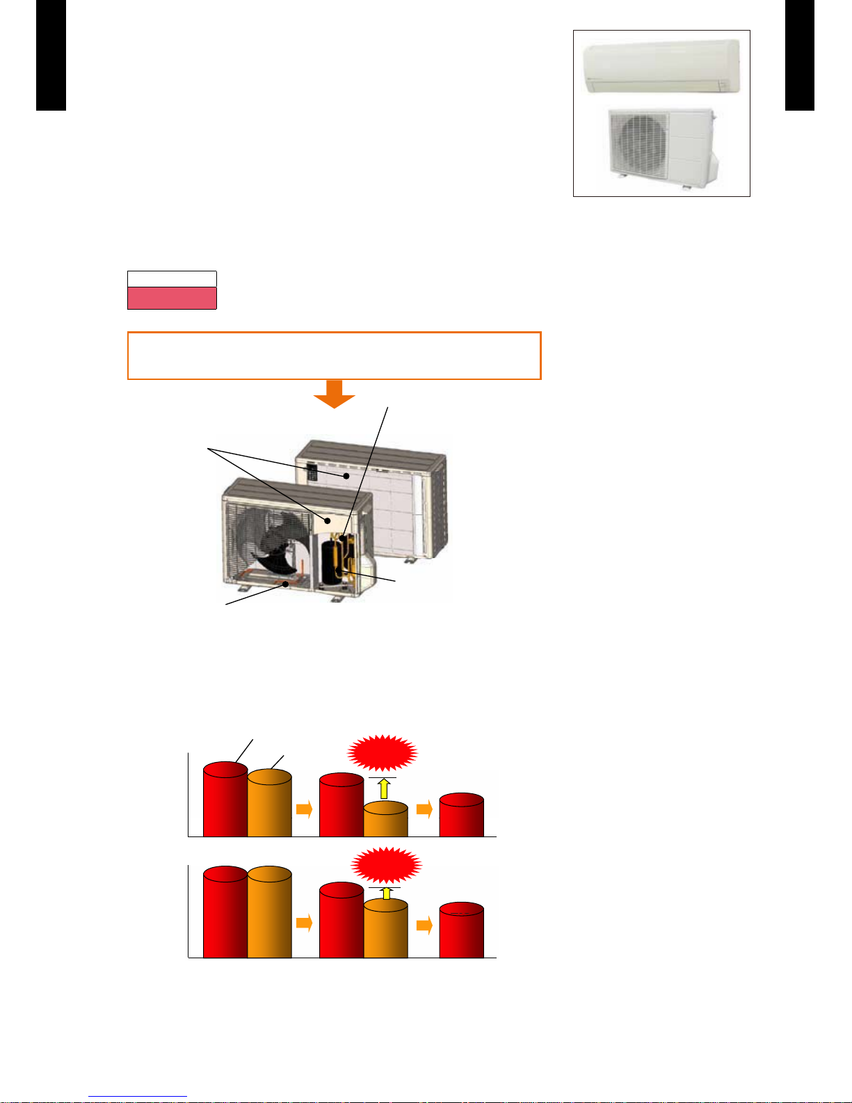
FEATURES
Low outdoor air temperature correspondence
Corresponds to heating operation at -25°C outdoor air temperature
Heating
-25 to 24
°C
Specification improvement that can be operated under
extreme low outdoor temperature (-25°C) without trouble
New model
Freezing
prevention of bace
Structural
improvements
Expansion of
mechanical space
Improvement of coldproof specifications
of parts
Powerful Heating at low outdoor temperature
Keeping the high heating capacity at low outdoor temperature.
45%up
3.5
3.2
2.2
2.6
3.3
4.1
3.5
4.1
3.0
17%up
2.9
Heating capacity
(kW)
Outdoor temperature
New model
Current model
Heating capacity
(kW)
2.5 kW
Class
2°C -7°C -15°C
3.4 kW
Class
Page 5
- (01 - 02) -
WALL MOUNTED TYPE
AS
A09-12LE
WALL MOUNTED TYPE
AS
A09-12LE
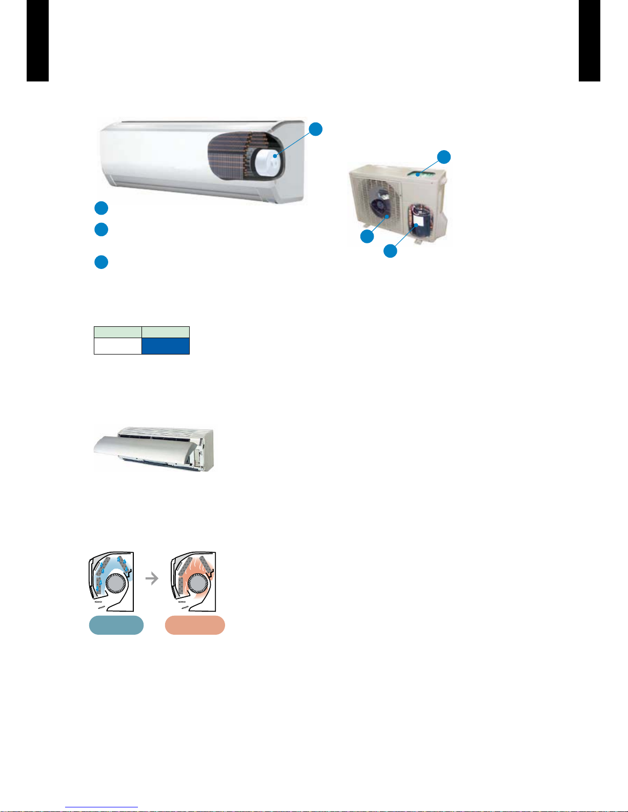
Energy-Efficiency classification A
Europe Energy-Efficiency classification A achieved
ALL DC
Super quiet
Air flow mode can be set in 4 steps and more detailed air flow setting is possible.
Fan speed Noise level
Quiet 21
dB(A)
Easy maintenance
Easy maintenance and always clean. Troublesome maintenance has been made easy.
Since the front panel is easy to remove, maintenance is also easy.
Inner drying operation
This model is equipped with an inner drying function. After the power is turned off, the dry starts
inside the air conditioner. This prevents the growth of mold and bacteria inside the air conditioner.
Corresponds to maximum 20m long piping
b
DC
compressor
c
a
b
a
a
c
When operation starts, the machine operates at high voltage and high power
and when operation stabilizes, the set temperature is maintained at low voltage.
PAM control
DC fan motor
Front view
During dew
condensation
Approx. 90 mins
Drying
Page 6
- (01 - 03) -
WALL MOUNTED TYPE
AS
A09-12LE
WALL MOUNTED TYPE
AS
A09-12LE
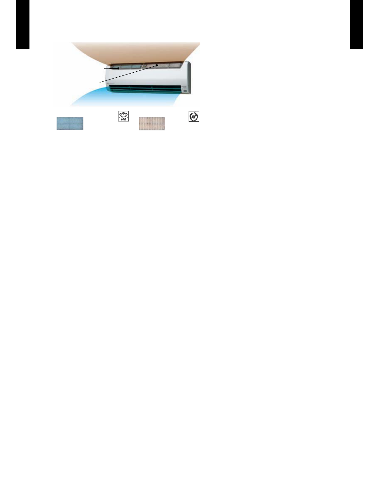
Air conditioner filter features
Applecatechin Filter
Long-life Ion
Deodorization Filter
Ion Deodorization Filter
Apple-catechin Filter
Dirty Air
Clean Air
Page 7
- (01 - 04) -
WALL MOUNTED TYPE
AS
A09-12LE
WALL MOUNTED TYPE
AS
A09-12LE
WIRELESS REMOTE CONTROLLER2.
FEATURES
Four kinds of timer setup
(On / Off / Program / Sleep) are possible.
Four kinds of timers. Easy operation.
Easy to change transmission code (4 patterns) by button operation.
Simple function setting
Setting of the air conditioner selection function is performed by remote controller.
Built-in timers
Select from four different timer programs (On/Off/Program/Sleep).
Program timer
The program timer operates the on and off timer once within a 24 hour period.
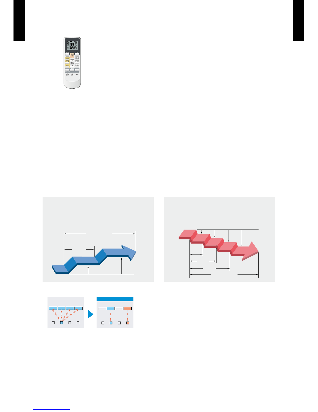
Sleep timer
The sleep timer function automatically corrects the temperature thermostat setting according to
the timer setting to prevent excessive cooling and heating while sleeping.
60min.
1 °C
2 °C
Timer setting
Set
temp.
1 °C
30min.
60min.
90min.
2 °C
3 °C
4 °C
Set
temp.
Timer setting
Cooling operation/dry operation
When the sleep timer is set, the set temperature
automatically rises 1 °C every hour. The set
temperature can rise up to a maximum of 2 °C.
Heating operation
When the sleep timer is set, the set temperature
automatically drops 1 °C every 30 minutes. The set
temperature can drop to a maximum of 4 °C.
Switching remote controller signal code
ABC D
ABCD
Mixed-up
I.U. I.U. I.U. I.U.
I.U. I.U. I.U. I.U.
After code change
Code selector switch eliminates unit
•
being wrongly switched.
(Up to 4 codes can be set.)
*I.U.=Indoor unit
Page 8
- (01 - 05) -
WALL MOUNTED TYPE
AS
A09-12LE
WALL MOUNTED TYPE
AS
A09-12LE
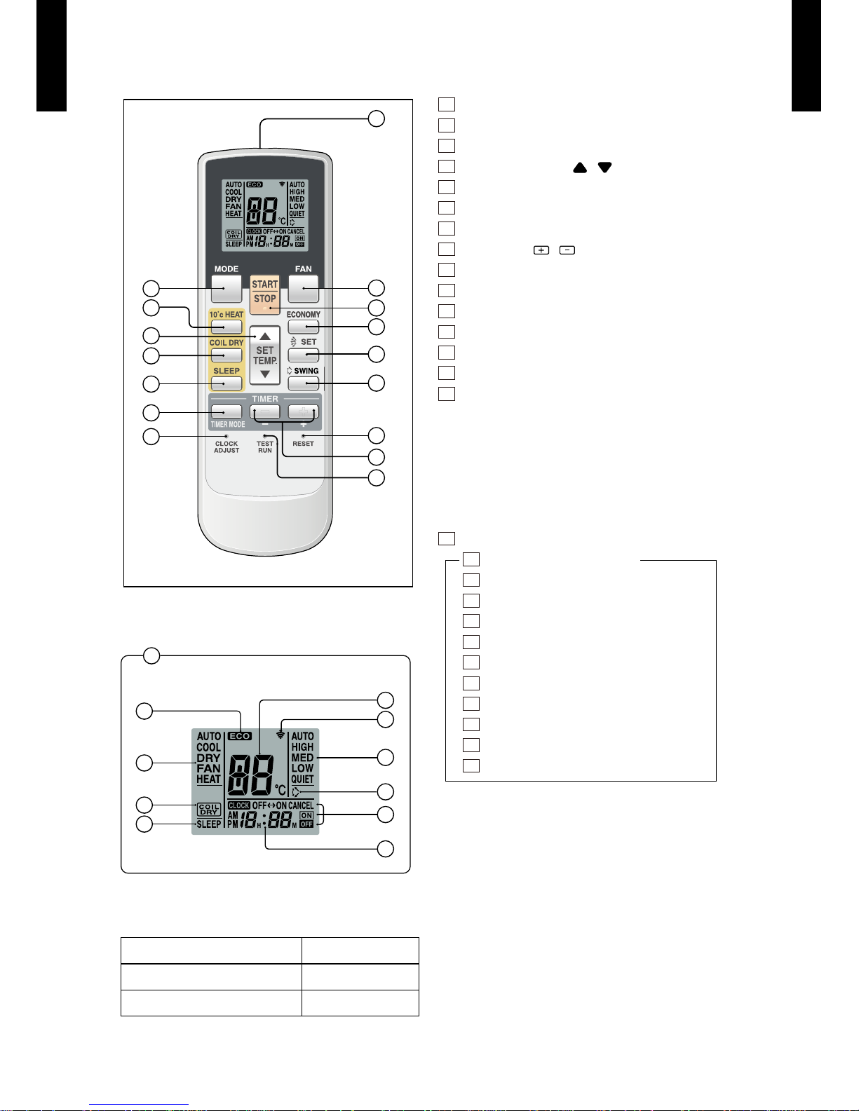
FUNCTIONS
Display panel
SPECIFICATION
12
10
11
9
6
13
14
8
15
7
1
5
4
3
2
16
17
20
21
25
26
18
24
23
27
22
19
SIZE (H x W x D mm) 176 x 56 x 18
WEIGHT ( g ) 110
ACCESSORY Holder
1
START/STOP button
2
MODE button
3
10°C HEAT button
4
SET TEMP. button ( / )
5
COIL DRY button
6
Signal transmitter
7
TIMER MODE button
8
TIMER SET ( / ) button
9
FAN b utton
10
ECONOMY button
11
START/STOP button
12
SET button
13
SWING button
14
RESET button
15
TEST RUN button
This button is used when installing the air conditioner, and
should not be used under normal conditions, as it will cause the
indoor unit's thermostat function to operate incorrectly.
If this button is pressed during normal operation, the indoor
unit will switch to test operation mode, and the Indoor Unit’s
OPERATION Indicator Lamp and TIMER Indicator Lamp will
begin to flash simultaneously.
To stop the test operation mode, press the START/STOP button
to stop the air conditioner.
16
CLOCK ADJUST button
17
Remote controller display
18
Transmit indicator
19
Clock display
20
ECONOMY display
21
Operating mode display
22
Timer mode display
23
Fan speed display
24
Temperature set display
25
COIL DRY display
26
SLEEP display
27
SWING display
Page 9
- (01 - 06) -
WALL MOUNTED TYPE
AS
A09-12LE
WALL MOUNTED TYPE
AS
A09-12LE
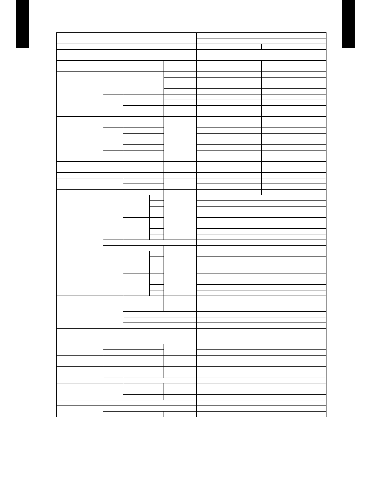
SPECIFICATIONS3.
Note :
Specifications are based on the following conditions.
Coolin g : Indoor tem perature of 2 7 °CDB / 19 °CWB. and outdoo r temperatu re of 35 °CDB /24 °CWB.
Heating : I ndoor temp erature of 2 0 °CDB / 15 °CWB. and outdoor t emperatu re of 7 °CDB/6 ° CWB.
Pipe leng th : 5 m, Height d ifferen ce : 0 m.(Outdoo r unit - Indoo r unit)
Typ e
WALL MOUNTED
INVERTER HEAT PUMP
Model name ASA09LEC ASA12LEC
Power source 230V~ 50Hz
Available voltage range 198-26 4V ~ 50Hz
European energy label
Cooling A A
Heating A A
Capacity
Cooling
Rated
kW 2.50 3.40
BTU/h 8,500 11,600
Min-Max
kW 0.5 - 3.2 0.9 - 3.9
BTU/h 1,700 - 10,90 0 3,100 - 13,300
Heating
Rated
kW 3.20 4.00
BTU/h 10,900 13,600
Min-Max
kW 0.5 - 4.5 0.9 - 5.6
BTU/h 1,700 - 15,300 3,100 - 19,100
Input power
Cooling
Rated
kW
0.63 0.895
Min-Max 0.25 - 1.27 0.25 - 1.40
Heating
Rated 0.75 0.97
Min-Max 0.25 - 1.60 0.25 - 1.99
Current
Cooling
Rated
A
3.2 4.3
Max 6.0 6.5
Heating
Rated 3.7 4.6
Max 9.5 9.0
EER Cooling
kW/kW
3.97 3.80
COP Heating 4.27 4.12
SENSIBLE CAPACITY Cooling kW 1.60 2.20
POWER FACTOR
Cooling
%
87 91
Heating 89 92
Moisture removal l/h (pints/h) 1.3 ( 2.7 ) 1.8 ( 3.8 )
Fan
Airflow
rate
Cooling
High
m
3
/h
735
Med 595
Low 425
Quiet 285
Heating
High 735
Med 595
Low 425
Quiet 285
Type × Q'ty Cross flow fan×1
Motor output W 30
Sound pressure level
Cooling
High
dB(A)
43
Med 38
Low 33
Quiet 21
Heating
High 43
Med 38
Low 33
Quiet 21
Heat exchanger type
Dimensions
(H × W × D)
mm
256 × 630 × 20
Fin pitch 1.1
Rows x Stages 2 × 16
Pipe type Copper
Fin type Aluminium
Enclosure
Material Polystyrene
Colour
White
Approximate colour of MUNSELL N 9.25/
Dimensions
( H×W ×D )
Net
mm
260 × 790 × 2 02
Gross 259 × 840 × 328
Weight
Net
kg(lb.)
7.5 (1 7)
Gross 9.5 (20)
Connection pipe
Size
Liquid
mm
Φ6.35 (Φ 1/4 in.)
Gas Φ9.52 (Φ 3 /8 in.)
Method Flare
Operation range
Cooling
°C 18 to 32
%RH 80 or less
Heating °C 30 or less
Remote controller type Wireless
Drain pipe
Material PP + LLDPE
Size mm Outer diameter: 21 / Inner diameter: 13.6
Page 10
- (01 - 07) -
WALL MOUNTED TYPE
AS
A09-12LE
WALL MOUNTED TYPE
AS
A09-12LE
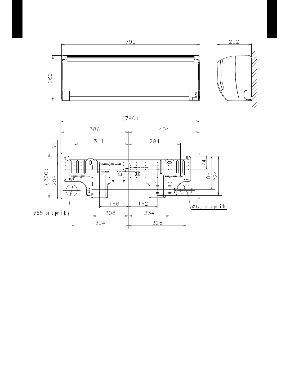
DIMENSIONS4.
MODEL :ASA09LE, ASA12LE
(Unit : mm)
Page 11
- (01 - 08) -
WALL MOUNTED TYPE
AS
A09-12LE
WALL MOUNTED TYPE
AS
A09-12LE
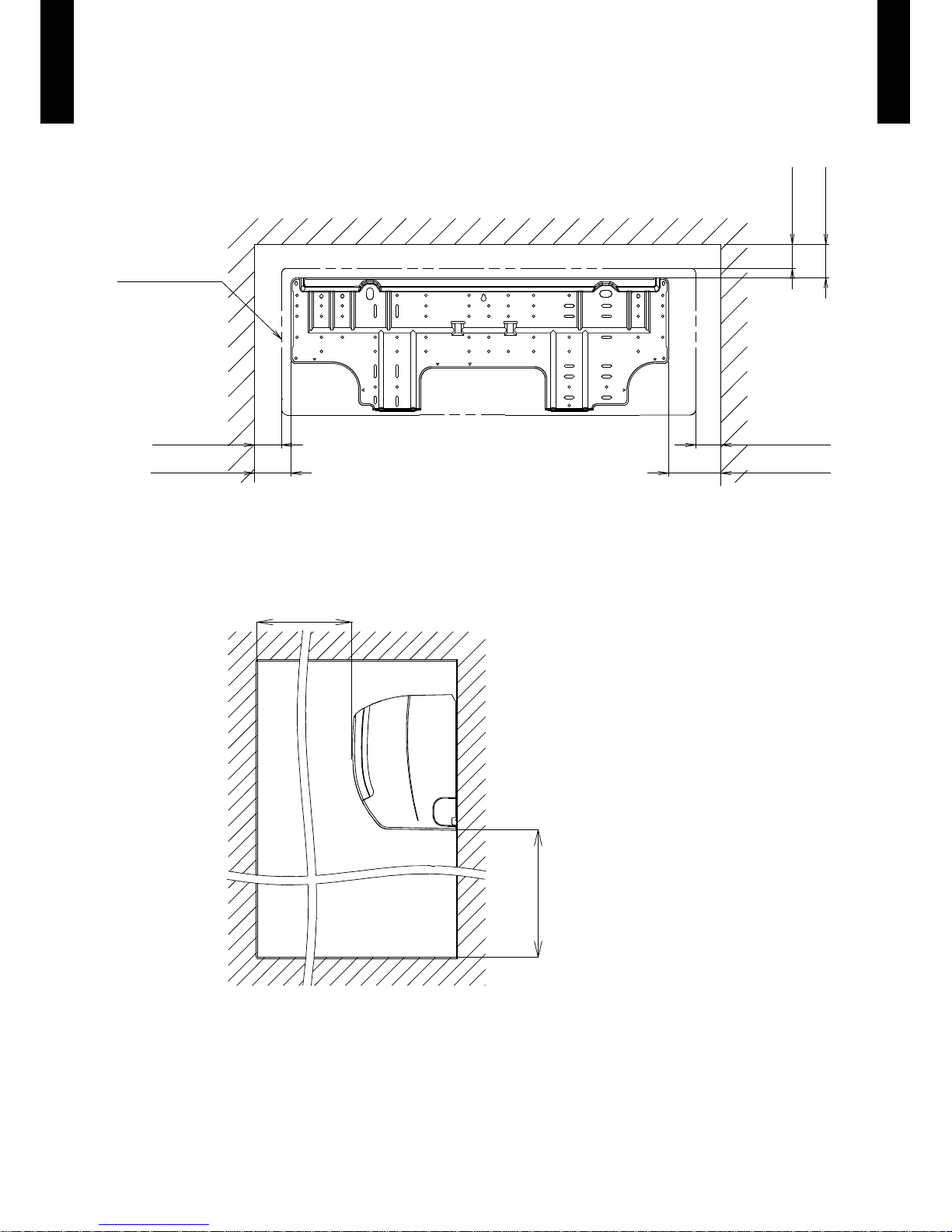
INSTALLATION PLACE
(Unit : mm)
Outline of
indoor unit
52 or more
70 or more
48 or more
100 or more
45 or more
63 or more
1800 or more
1500 or more
Page 12
- (01 - 09) -
WALL MOUNTED TYPE
AS
A09-12LE
WALL MOUNTED TYPE
AS
A09-12LE
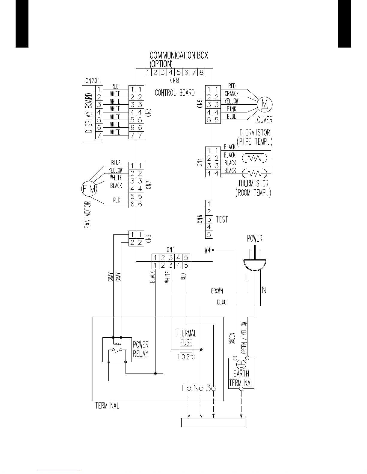
WIRING DIAGRAMS5.
MODEL :ASA09LE, ASA12LE
TO OUTDOOR UNIT
Page 13

- (01 - 10) -
WALL MOUNTED TYPE
AS
A09-12LE
WALL MOUNTED TYPE
AS
A09-12LE
CAPACITY TABLE6.
COOLING CAPACITY6-1.
MODEL :ASA09LE
MODEL :ASA12LE
AFR : Air fl ow rate (m3/min)
TC : Total capaci ty (kW)
SHC : Sens ible Heat c apacity (k W)
PI : Power Inpu t (kW)
AFR 12.5
Indoor temperature
°CDB 18 21 23 25 27 29 32
°CWB 12 15 16 18 19 21 23
Outdoor temperature
°CDB TC SHC PI TC SHC PI TC SHC PI TC SHC PI TC SHC PI TC SHC PI TC SHC PI
10 2.22 1.52 0.24 2.48 1.53 0.25 2.56 1.66 0.25 2.73 1.67 0.25 2.81 1.80 0.25 2.98 1.79 0.25 3.15 1.91 0.26
15 2.22 1.52 0.21 2.47 1.53 0.22 2.56 1.66 0.22 2.73 1.67 0.22 2.81 1.80 0.22 2.98 1.79 0.22 3.15 1.91 0.23
20 2.33 1.59 0.43 2.59 1.60 0.44 2.68 1.74 0.44 2.86 1.75 0.44 2.95 1.89 0.45 3.12 1.88 0.45 3.30 2.00 0.45
25 2.22 1.51 0.49 2.47 1.52 0.50 2.55 1.66 0.50 2.72 1.66 0.51 2.80 1.79 0.51 2.97 1.79 0.51 3.14 1.90 0.52
30 2.10 1.43 0.55 2.34 1.44 0.56 2.42 1.57 0.56 2.58 1.57 0.57 2.66 1.70 0.57 2.82 1.69 0.57 2.98 1.80 0.58
35 1.98 1.35 0.61 2.20 1.36 0.62 2.28 1.48 0.62 2.43 1.48 0.63 2.50 1.60 0.63 2.65 1.59 0.64 2.80 1.70 0.64
40 1.84 1.26 0.67 2.05 1.27 0.68 2.12 1.38 0.69 2.26 1.38 0.69 2.33 1.49 0.70 2.47 1.49 0.70 2.61 1.58 0.71
43 1.72 1.18 0.68 1.92 1.19 0.69 1.99 1.29 0.69 2.12 1.29 0.70 2.18 1.40 0.70 2.31 1.39 0.71 2.44 1.48 0.72
AFR 12.5
Indoor temperature
°CDB 18 21 23 25 27 29 32
°CWB 12 15 16 18 19 21 23
Outdoor temperature
°CDB TC SHC PI TC SHC PI TC SHC PI TC SHC PI TC SHC PI TC SHC PI TC SHC PI
10 2.92 2.02 0.27 3.25 2.03 0.27 3.36 2.21 0.27 3.58 2.21 0.27 3.70 2.39 0.28 3.92 2.38 0.28 4.14 2.54 0.28
15 2.83 1.95 0.35 3.15 1.96 0.35 3.25 2.14 0.35 3.47 2.14 0.36 3.58 2.31 0.36 3.79 2.30 0.36 4.01 2.46 0.37
20 3.13 2.17 0.60 3.49 2.18 0.60 3.61 2.37 0.61 3.85 2.38 0.61 3.97 2.57 0.62 4.21 2.56 0.62 4.44 2.72 0.63
25 3.00 2.07 0.68 3.34 2.09 0.69 3.45 2.27 0.70 3.68 2.27 0.70 3.80 2.46 0.71 4.02 2.45 0.71 4.25 2.61 0.72
30 2.85 1.97 0.77 3.17 1.98 0.78 3.28 2.15 0.79 3.50 2.16 0.80 3.61 2.33 0.80 3.82 2.32 0.81 4.04 2.48 0.82
35 2.69 1.86 0.86 2.99 1.87 0.88 3.09 2.03 0.88 3.30 2.04 0.89 3.40 2.20 0.895 3.60 2.19 0.90 3.81 2.33 0.91
40 2.47 1.71 0.92 2.75 1.72 0.94 2.84 1.87 0.94 3.03 1.87 0.95 3.12 2.02 0.96 3.31 2.01 0.97 3.50 2.14 0.98
43 2.27 1.57 0.92 2.53 1.58 0.93 2.62 1.72 0.93 2.79 1.72 0.94 2.88 1.86 0.95 3.05 1.85 0.96 3.22 1.98 0.97
Page 14

- (01 - 11) -
WALL MOUNTED TYPE
AS
A09-12LE
WALL MOUNTED TYPE
AS
A09-12LE
HEATING CAPACITY6-2.
This table is created using the maximum capacity.
MODEL :
ASA09LE
MODEL :
ASA12LE
AFR : Air flo w rate (m3/min)
TC : Total capaci ty (kW)
PI : Power Inpu t (kW)
AFR 12.5
Indoor temperature
°CDB 16 18 20 22 24
Outdoor temperature
°CDB °CWB TC PI TC PI TC PI TC PI TC PI
-25 -26 2.88 1.07 2.81 1.09 2.74 1.11 2.68 1.14 2.61 1.16
-20 -21 3.21 1.28 3.13 1.31 3.05 1.34 2.98 1.36 2.90 1.39
-15 -16 3.48 1.50 3.39 1.53 3.31 1.56 3.23 1.59 3.15 1.62
-10 -11 3.75 1.71 3.66 1.75 3.57 1.78 3.48 1.82 3.39 1.85
-5 -7 4.0 3 1.70 3.9 4 1.73 3.84 1.7 7 3.75 1.80 3 .65 1.84
0 -2 4.14 1.70 4.04 1.73 3. 94 1.77 3.84 1.80 3.74 1.84
5 3 4.64 1.70 4.53 1.73 4.42 1.77 4.31 1.80 4.20 1.84
7 6 5.04 1.70 4.92 1.73 4.80 1.77 4.68 1.80 4.56 1. 84
10 8 5. 38 1.70 5.25 1.73 5.12 1.77 4.99 1. 80 4.87 1.84
15 10 5.69 1.70 5.55 1.73 5.42 1.77 5.28 1.80 5.15 1.84
AFR 12.5
Indoor temperature
°CDB 16 18 20 22 24
Outdoor temperature
°CDB °CWB TC PI TC PI TC PI TC PI TC PI
-25 -26 3.07 1.09 3.00 1.12 2.92 1.14 2.85 1.16 2.78 1.18
-20 -21 3.35 1.28 3.27 1.31 3.19 1.34 3.11 1.36 3.03 1.39
-15 -16 3.73 1.47 3.64 1.50 3.56 1.54 3.47 1.57 3.38 1.60
-10 -11 4.2 2 1.6 6 4.12 1.70 4.02 1.73 3. 92 1.77 3.82 1.80
-5 -7 4.65 1.73 4.54 1.77 4.43 1.80 4.32 1.84 4.20 1.87
0 -2 4.81 1.88 4.69 1.92 4.58 1.96 4.47 2.00 4.35 2.04
5 3 5.64 1.68 5.51 1.71 5.37 1.75 5.24 1.78 5.10 1.82
7 6 5.88 1.70 5.74 1.73 5.60 1.77 5.46 1.80 5.32 1.84
10 8 6.18 1.71 6.03 1.75 5.88 1.78 5.74 1.82 5. 59 1. 85
15 10 6.42 1.72 6.26 1.75 6.11 1.79 5.96 1. 83 5.81 1.86
Page 15

- (01 - 12) -
WALL MOUNTED TYPE
AS
A09-12LE
WALL MOUNTED TYPE
AS
A09-12LE
FAN PERFORMANCE AND CAPACITY7.
AIR VELOCITY DISTRIBUTION7-1.
MODEL :ASA09LE, ASA12LE
Note:
Fan spee d:High
Operation mode:FAN
Volt age: 230 V
2.0
1.0
0.5
2
1
0
1
2
Unit : m/s(m)
(m)
TOP VIEW
Vertic al flap : Up
Horizo ntal flap : Cen ter
012345678
0.5
0.5
1.0
1.0
2.0
2.0
3
2
1
0
1
2
3
Unit : m/s(m)
TOP VIEW
Vertic al flap : Up
Horizo ntal flap : Ri ght & Left
(m)
012345678
2.0
1.0
0.5
3
2
1
0
Unit : m/s(m)
SIDE VIEW
Vertic al flap : Up
Horizo ntal flap : Cen ter
(m)
012345678
2.0
1.0
0.5
3
2
1
0
Unit : m/s(m)
SIDE VIEW
Vertic al flap : Down
Horizo ntal flap : Cen ter
(m)
012345678
Page 16

- (01 - 13) -
WALL MOUNTED TYPE
AS
A09-12LE
WALL MOUNTED TYPE
AS
A09-12LE
AIR FLOW7-2.
MODEL :ASA09LE, ASA12LE
COOLING
HEATING
Fan speed
Number of
rotations
(r.p.m)
Air flow
HIGH
1440
735
m³/h
204
l/s
432
CFM
MED
1200
595
m³/h
165
l/s
350
CFM
LOW
920
425
m³/h
118
l/s
250
CFM
QUIET
680
285
m³/h
79
l/s
168
CFM
Fan speed
Number of
rotations
(r.p.m)
Air flow
HIGH
1440
735
m³/h
204
l/s
432
CFM
MED
1200
595
m³/h
165
l/s
350
CFM
LOW
980
465
m³/h
129
l/s
274
CFM
QUIET
700
295
m³/h
82
l/s
174
CFM
Page 17

- (01 - 14) -
WALL MOUNTED TYPE
AS
A09-12LE
WALL MOUNTED TYPE
AS
A09-12LE
OPERATION NOISE8.
NOISE LEVEL CURVE8-1.
MODEL :ASA09LE
COOLING
Octave ba nd sound pr essure leve l, dB:(0dB= 0.0002μbar)
Octave band center frequency,Hz
80
70
60
50
40
30
20
10
0
63 125 250 500 1,000 2,000 4,000 8,000
NC-65
NC-60
NC-55
NC-50
NC-45
NC-40
NC-35
NC-30
NC-25
NC-20
NC-15
High
Quiet
HEATING
Octave ba nd sound pr essure leve l, dB:(0dB= 0.0002μbar)
Octave band center frequency,Hz
80
70
60
50
40
30
20
10
0
63 125 250 500 1,000 2,000 4,000 8,000
NC-65
NC-60
NC-55
NC-50
NC-45
NC-40
NC-35
NC-30
NC-25
NC-20
NC-15
High
Quiet
NC-65
NC-60
NC-55
NC-50
NC-45
NC-40
NC-35
NC-30
NC-25
NC-20
NC-15
Octave ba nd sound pr essure leve l, dB:(0dB= 0.0002μbar)
Octave band center frequency,Hz
80
70
60
50
40
30
20
10
0
63 125 250 500 1,000 2,000 4,000 8,000
MODEL :ASA12LE
COOLING
High
Quiet
HEATING
Octave ba nd sound pr essure leve l, dB:(0dB= 0.0002μbar)
Octave band center frequency,Hz
80
70
60
50
40
30
20
10
0
63 125 250 500 1,000 2,000 4,000 8,000
NC-65
NC-60
NC-55
NC-50
NC-45
NC-40
NC-35
NC-30
NC-25
NC-20
NC-15
High
Quiet
Page 18

- (01 - 15) -
WALL MOUNTED TYPE
AS
A09-12LE
WALL MOUNTED TYPE
AS
A09-12LE
SOUND LEVEL CHECK POINT8-2.
Page 19

- (01 - 16) -
WALL MOUNTED TYPE
AS
A09-12LE
WALL MOUNTED TYPE
AS
A09-12LE
ELECTRIC CHARACTERISTICS9.
Model Name ASA09LE ASA12LE
Power Supply
Voltage V 230 ~
Frequency Hz 50
Max Operating Current A 9.5 11.0
*)Wiring Spec
Circuit breaker A 15
Connection Cable mm
2
1.5
Limited wiring length m 20
*) Wiring Spec
Selected Sample
(Selected based on Japan Electrotechnical Standard and Codes Committee E0005)
Page 20

- (01 - 17) -
WALL MOUNTED TYPE
AS
A09-12LE
WALL MOUNTED TYPE
AS
A09-12LE
SAFETY DEVICES10.
Protection form
Model
ASA09LE ASA12LE
Circuit protection Current fuse (PCB)
3.15A 250V
Terminal protection Current (thermal) fuse
3A 250V 102°C
Fan motor protection Terminal protection program
MAX. 120±15°C
Page 21

- (01 - 18) -
WALL MOUNTED TYPE
AS
A09-12LE
WALL MOUNTED TYPE
AS
A09-12LE
EXTERNAL INPUT & OUTPUT11.
Connector
INPUT
OUTPUT REMARKS
CN303 Control input -
See external input/
output settings for
details.
CN304 -
Operation status
output
EXTERNAL INPUT11-1.
CONTROL INPUT (Operation/Stop)
The air conditioner can be remotely operated by means of the following on-site work.
Operation is started at the following contents by adding the contact input of a commercial ON/OFF switch to a
connector on the external control PC board and turning it ON.
Initial starting after power turned on Starting other than at the left
Operation mode Auto changeover Mode at previous operation
Set temperature 24°C Temperature at previous operation
Air flow mode AUTO Mode at previous operation
Up-down air direction (swing) Standard air direction (swing OFF) Air direction at previous operation
Left-right air direction (swing) Standard air direction (swing OFF) Air direction at previous operation
Circuit diagram example
Signal
Field supply
Indoor
control PC board Communication kit
Optional parts
Connector
1
3
*10 m
Connected unit
Ex.) Switch
Operation
Stop
ON
OFF
Input signal
Indoor unit
Parts (Optional)
Parts name Model name
External connect kit UTY-XWZX
Communication box kit UTY-XCBXE
* For operating the EXTERNAL INPUT function, the Compact wall mounted type requires the communication kit
(UTY-XCBXE) in addition to the wire (UTY-XWZX).
Wire (External input) : UTY-XWZX
Page 22

- (01 - 19) -
WALL MOUNTED TYPE
AS
A09-12LE
WALL MOUNTED TYPE
AS
A09-12LE
EXTERNAL OUTPUT11-2.
OPER ATION STATUS O UTPUT
An air conditioner operation status signal can be output.
Circuit diagram example
Field supply
Optional parts
Ex.)Display
Indoor
control PC board Communication kit Connected unit
Ex.)Relay unit
1
2
Signal
Relay
power
supply
V
Connector
*10 m
24V DC
ON
OFF
Operation
Stop
Indoor unit
Output signal
Parts (Optional)
Parts name Model name
External connect kit UTY-XWZX
Communication box kit UTY-XCBXE
* For operating the EXTERNAL INPUT function, the Compact wall mounted type requires the communication kit
(UTY-XCBXE) in addition to the wire (UTY-XWZX).
Wire (External input) : UTY-XWZX
Page 23

- (01 - 20) -
WALL MOUNTED TYPE
AS
A09-12LE
WALL MOUNTED TYPE
AS
A09-12LE
FUNCTION SETTING12.
INDOOR UNIT (Setting by remote controller)12-1.
This procedure changes to the function settings used to control the indoor unit according to the •
installation conditions. Incor settings can cause the indoor unit malfunction.
After the power is turned on, perform the “FUNCTION SETTING” according to the installation •
conditions using the remote controller.
The settings may be selected between the following two: Function Number or Setting Value. •
Settings will not be changed if invalid numbers or setting values are selected. •
FUNCTION SETTING METHOD (for Wireless remote controller)
Entering the Function Setting Mode
While pressing the FAN button and SET TEMP. (
•
) simultaneously, press the RESET button to enter the function
setting mode.
STEP 1
Setting the Remote controller Signal Code
Use the following steps to select the signal code of the remote controller. (Note
that the air conditioner cannot receive a signal code if the air conditioner has not
been set for the signal code.) The signal codes that are set through this process are
applicable only to the signals in the FUNCTION SETTING. For details on how to set
the signal codes through the normal process, refer to SELECTING THE REMOTE
CONTROLLER SIGNAL CODE.
Press the SET TEMP. (1.
) ( ) button to change the signal code between →
→
→ Match the code on the display to the air conditioner signal code. (initially
set to
)
(If the signal code does not need to be selected, press the MODE button and
proceed to STEP 2.)
Press the TIMER MODE button and check that the indoor unit can receive signals 2.
at the displayed signal code.
Press the MODE button to accept the signal code, and proceed to STEP 2.3.
The air conditioner signal code is set to A prior to shipment.
The remote controller resets to signal code A when the batteries in the remote controller are replaced. If you use a
signal code other than signal code A, reset the signal code after replacing the batteries.
If you do not know the air conditioner signal code setting, try each of the signal codes (
→ → → ) until you
find the code which operates the air conditioner.
STEP 2
Selecting the Function Number and Setting Value
Press the SET TEMP. (1.
) ( ) buttons to select the function
number.
(Press the MODE button to switch between the left and right
digits.)
Press the FAN button to proceed to setting the value. 2.
Press the FAN button again to return to the function number
selection.)
Press the SET TEMP. (3.
) ( ) buttons to select the setting
value.
(Press the MODE button to switch between the left and right
digits.)
Press the TIMER MODE button, and START/STOP button, 4.
in the order listed to confirm the settings.
Press the RESET button to cancel the function setting 5.
mode.
After completing the FUNCTION SETTING, be sure to turn 6.
off the power and turn it on again.
Function number
Setting value
CAUTION
After turning off the power, wait 10 seconds or more before turning on it again.
The FUNCTION SETTING doesn’t become effective if it doesn’t do so.
Page 24

- (01 - 21) -
WALL MOUNTED TYPE
AS
A09-12LE
WALL MOUNTED TYPE
AS
A09-12LE
CONTENTS OF FUNCTION SETTING
Follow the instructions in the Local Setup Procedure, which is supplied with the remote control, in •
accordance with the installed condition.
After the power is turned on, perform the Function Setting on the remote control.
The settings may be selected between the following two: Function Number or Setting Value. •
Settings will not be changed if invalid numbers or setting values are selected. •
Wall
Mounted
1-1 Cooler room temperature correction ●
1-2 Heater room temperature correction ●
1-3 Auto Restart ●
1-4 Indoor Room Temperature Sensor ●
1-5 Remote controller Signal Code ●
1-1. Setting the Cooler Room Temperature Correction
Depending on the installed environment, the room temperature sensor may require a correction.
The settings may be selected as shown in the table below.
(. . .Factory setting)
Setting Description Function Number Setting Value
Standard
30
00
Lower control 01
1-2. Setting the Heater Room Temperature Correction
Depending on the installed environment, the room temperature sensor may require a correction.
The settings may be changed as shown in the table below.
(. . .Factory setting)
Setting Description Function Number Setting Value
Standard
31
00
Lower control 01
Slightly warmer control 02
Warmer control 03
Page 25

- (01 - 22) -
WALL MOUNTED TYPE
AS
A09-12LE
WALL MOUNTED TYPE
AS
A09-12LE
The following settings are also possible, depending on the operating conditions.
1-3. Auto Restart
(. . .Factory setting)
Setting Description Function Number Setting Value
Yes
40
00
No 01
1-4. Indoor Room Temperature Sensor Switching Function
(Only for Wired remote controller)
The following settings are needed when use the control by Wired remote controller temperature
sensor.
(. . .Factory setting)
Setting Description Function Number Setting Value
No
42
00
Yes 01
If setting value is “00”,
•
room temperature is controlled by the indoor unit temperature sensor.
If setting value is “01”,
•
room temperature is controlled by either indoor unit temperature sensor or remote controller unit sensor.
1-5. Setting the Remote controller Signal Code
Change the indoor unit Signal Code, depending on the remote controllers.
(. . .Factory setting)
Setting Description Function Number Setting Value
A
44
00
B01
C02
D03
REMOTE CONTROLLER SIGNAL CODE SETTING
Use the following steps to select the signal code of the remote controller.
(Note that the air conditioner cannot receive a signal code if the air conditioner has
not been set for the signal code.)
Press the START/STOP button until only the clock is displayed on the remote 1.
controller display.
Press the MODE button for at least five seconds to display the current signal code 2.
(initially set to
).
Press the SET TEMP. (3.
) ( ) button to change the signal code between →
→
→ .
Match the code on the display to the air conditioner signal code.
Press the MODE button again to return to the clock display. The signal code will 4.
be changed.
If no buttons are pressed within 30 seconds after the signal code is displayed, the system returns to the original
clock display. In this case, start again from step 1.
The air conditioner signal code is set to A prior to shipment.
Contact your retailer to change the signal code.
The remote controller resets to signal code A when the batteries in the remote controller are replaced. If you use
a signal code other than signal code A, reset the signal code after replacing the batteries. If you do not know the
air conditioner signal code setting, try each of the signal codes (
→ → → ) until you find the code which
operates the air conditioner.
Page 26

- (01 - 23) -
WALL MOUNTED TYPE
AS
A09-12LE
WALL MOUNTED TYPE
AS
A09-12LE
OPTIONAL PARTS13.
Exterior Parts name Model No. Summary
Apple-catechin
filter
UTR-FA16
Fine dust, invisible mold
spores, and harmful
microorganisms are absorbed
onto the filter by static
electricity, and further growth
is inhibited and deactivated
by the polyphenol ingredient
extracted from apples.
Ion
deodorization
filter
UTR-FA16-2
The filter deodorizes by
powerfully decomposing
absorbed odors using the
oxidizing and reducing effects
of ions generated by the ultra
fine-particle ceramic.
Communication
box kit
UTY-XCBXE
Use to connect with optional
devices and air conditioner
PC board.
SUMOTUWETH FR
SA
AM
PM
369
12 15 18 21
Wired remote
controller
UTB-UD
Unit control is performed by
wired remote controller.
External
connect kit
UTY-XWZX
Use to connect with various
peripheral devices and air
conditioner PC board.
Page 27

2.OUTDOOR UNIT
SINGLE TYPE :
AO
R09LECN
AO
R12LECN
DTR_AO069E_01
2010.10.05
Page 28

OUTDOOR UNIT
AO
R09-12LE
OUTDOOR UNIT
AO
R09-12LE
CONTENTS
2. OUTDOOR UNIT
1. SPECIFICATIONS
.............................................................................................. 02 - 01
2. DIMENSIONS
........................................................................................................ 02 - 02
3. REFRIGERANT CIRCUIT
............................................................................ 02 - 03
4. WIRING DIAGRAMS
........................................................................................ 02 - 04
5. CAPACITY COMPENSATION RATE FOR PIPE LENGTH AND
HEIGHT DIFERENCE
...................................................................................... 02 - 05
6. ADDITIONAL CHARGE CALCULATION
......................................... 02 - 07
7. AIR FLOW
................................................................................................................ 02 - 08
8. OPERATION NOISE
......................................................................................... 02 - 09
8-1. NOISE LEVEL CURVE
.................................................................................... 02 - 09
8-2. SOUND LEVEL CHECK POINT
..................................................................... 02 - 10
9. ELECTRIC CHARACTERISTICS
............................................................02 - 11
10. SAFETY DEVICES
............................................................................................ 02 - 12
Page 29
- (02 - 01) -
OUTDOOR UNIT
AO
R09-12LE
OUTDOOR UNIT
AO
R09-12LE
SPECIFICATIONS1.
Note :
Specifications are based on the following conditions.
Coolin g : Indoor tem perature of 2 7 °CDB / 19 °CWB. and outdoo r temperatu re of 35 °CDB /24 °CWB.
Heating : I ndoor temp erature of 2 0 °CDB / 15 °CWB. and outdoor t emperatu re of 7 °CDB/6 ° CWB.
Pipe leng th : 5 m, Height d ifferen ce : 0 m.(Outdoo r unit - Indoo r unit)
Typ e INVERTER HEAT PUMP
Model name AOR09LECN AOR12LECN
Power source 230V~ 50Hz
Available voltage range 198-26 4V ~ 50Hz
Starting current A 3.7 4.6
Fan
Airflow
rate
Cooling
m
3
/h
2,020 1,950
Heating 1,760 1,700
Type × Q'ty Propeller fan×1
Motor output W 50
Sound pressure level
Cooling
dB(A)
48 49
Heating 47 48
Heat exchanger type
Dimensions
(H × W × D)
mm
508 × 89 6 × 22 504 × 896 × 18.2
Fin pitch 1.3 1.4
Rows x Stages 1 × 20 2 × 24
Pipe type Copper
Fin type Aluminium
Compressor
Type × Q'ty Rotary ×1
Motor output W 750
Refrigerant
Typ e R 410A
Charge g 950 1,000
Refrigerant oil Type POE(VG74)
Enclosure
Material Steel
Colour
Beige
Approximate colour of MUNSELL 10YR 7.5/1.0
Dimensions
( H×W×D)
Net
mm
540 × 790 × 290
Gross 648 × 910 × 380
Weight
Net
kg(lb.)
33 (72) 36 (79)
Gross 36 (79) 39 (85)
Connection pipe
Size
Liquid
mm
Φ6.35 (Φ 1/4 in.)
Gas Φ9.52 (Φ 3/8 in.)
Method Flare
Max. length
m
20(chargeless:15)
Max. height difference 15
Operation range
Cooling
°C
10 to 43
Heating -25 to 24
Page 30

- (02 - 02) -
OUTDOOR UNIT
AO
R09-12LE
OUTDOOR UNIT
AO
R09-12LE
INSTALLATION PLACE
If the space is larger that is stated, the condition will be the same as that are no obstacles.
600 mm or more
100 mm or more
200 mm or more
100 mm or more
250 mm or more
(Service space)
DIMENSIONS2.
MODEL :AOR09LE, AOR12LE
(Unit : mm)
Pitch of bolts for installation
Drain port Ø20
353
320
45.4
540
125
395
20
790
540
20
68
290
Page 31

- (02 - 03) -
OUTDOOR UNIT
AO
R09-12LE
OUTDOOR UNIT
AO
R09-12LE
REFRIGERANT CIRCUIT3.
MODEL :AOR09LE, AOR12LE
2-Way
valve
Strainer
Strainer
3-Way
valve
Muffler
4-Way valve
Expansion valve
Heat exchanger
( INDOOR )
Heat exchanger
( OUTDOOR )
Compressor
Cooling
Heatin
g
Refrigerant pipe diameter
Liquid : 1/4" (6.35 mm)
Gas : 3/8" (9.52 mm)
Page 32

- (02 - 04) -
OUTDOOR UNIT
AO
R09-12LE
OUTDOOR UNIT
AO
R09-12LE
WIRING DIAGRAMS4.
MODEL :AOR09LE, AOR12LE
Page 33

- (02 - 05) -
OUTDOOR UNIT
AO
R09-12LE
OUTDOOR UNIT
AO
R09-12LE
CAPACITY COMPENSATION RATE FOR PIPE LENGTH 5.
AND HEIGHT DIFERENCE
MODEL :AOR09LE
Height difference H
1 Indoor unit is upper than outdoor unit.
2 Indoor unit is under than outdoor unit.
Indoor unit
Indoor unit
Connection pipe
Outdoor unit
Outdoor unit
Connection pipe
HEATING
Pipe length (m)
57.5101520
Height difference H
(m)
1
Indoor unit is upper
than outdoor unit.
15
- - - 0.990 0.969
10
- - 1.002 0.990 0.969
7. 5
- 1.001 1.002 0.990 0.969
5
1.000 1.001 1.002 0.990 0.969
0
1.000 1.001 1.002 0.990 0.969
2
Indoor unit is under
than outdoor unit
-5
0.995 0.996 0.997 0.985 0.964
-7.5
- 0.994 0.995 0.983 0.962
-10
- - 0.992 0.980 0.960
-15
- - - 0.970 0.950
COOLING
Pipe length (m)
57.5101520
Height difference H
(m)
1
Indoor unit is upper
than outdoor unit.
15 - - - 0.913 0.922
10 - - 0.963 0.928 0.937
7.5 - 0.980 0.967 0.932 0.941
5 0.992 0.984 0.971 0.936 0.945
0 1.000 0.992 0.979 0.943 0.953
2
Indoor unit is under
than outdoor unit
-5 1.000 0.992 0.979 0.943 0.953
-7.5 - 0.992 0.979 0.943 0.953
-10 - - 0.979 0.943 0.953
-15 - - - 0.943 0.953
Page 34

- (02 - 06) -
OUTDOOR UNIT
AO
R09-12LE
OUTDOOR UNIT
AO
R09-12LE
MODEL :AOR12LE
Height difference H
1 Indoor unit is upper than outdoor unit.
2 Indoor unit is under than outdoor unit.
Indoor unit
Indoor unit
Connection pipe
Outdoor unit
Outdoor unit
Connection pipe
HEATING
Pipe length (m)
57.5101520
Height difference H
(m)
1
Indoor unit is upper
than outdoor unit.
15
---0.952 0.932
10
- - 1.002 0.952 0.932
7. 5
- 1.010 1.002 0.952 0.932
5
1.000 1.010 1.002 0.952 0.932
0
1.000 1.010 1.002 0.952 0.932
2
Indoor unit is under
than outdoor unit
-5
0.995 1.005 0.997 0.947 0.927
-7.5
- 1.002 0.994 0.945 0.925
-10
- - 0.992 0.942 0.923
-15
---0.933 0.913
COOLING
Pipe length (m)
57.5101520
Height difference H
(m)
1
Indoor unit is upper
than outdoor unit.
15
---0.882 0.880
10
- - 0.943 0.896 0.894
7. 5
- 0.968 0.947 0.900 0.898
5
0.992 0.972 0.951 0.903 0.901
0
1.000 0.980 0.958 0.911 0.909
2
Indoor unit is under
than outdoor unit
-5
1.000 0.980 0.958 0.911 0.909
-7.5
- 0.980 0.958 0.911 0.909
-10
- - 0.958 0.911 0.909
-15
---0.911 0.909
Page 35

- (02 - 07) -
OUTDOOR UNIT
AO
R09-12LE
OUTDOOR UNIT
AO
R09-12LE
ADDITIONAL CHARGE CALCULATION6.
MODEL :AOR09LE
REFRIGERANT CHARGE
MODEL :AOR12LE
REFRIGERANT CHARGE
Refrigerant type R410A
Refrigerant amount g 950
Pipe length m ~15 20
20g/m
Additional charge g 0 (Charge less) +100
Refrigerant type R410A
Refrigerant amount g 1000
Pipe length m ~15 20
20g/m
Additional charge g 0 (Charge less) +100
Page 36

- (02 - 08) -
OUTDOOR UNIT
AO
R09-12LE
OUTDOOR UNIT
AO
R09-12LE
AIR FLOW7.
MODEL :AOR09LE
COOLING
HEATING
MODEL :AOR12LE
COOLING
HEATING
Number of rotations
(r.p.m)
Air flow
850
2020 m
3
/h
561 l/s
118 9 C FM
Number of rotations
(r.p.m)
Air flow
750
1760
m3/h
489
l/s
1036
CFM
Number of rotations
(r.p.m)
Air flow
850
1950
m3/h
542
l/s
114 8
CFM
Number of rotations
(r.p.m)
Air flow
750
170 0
m3/h
472
l/s
1000
CFM
Page 37

- (02 - 09) -
OUTDOOR UNIT
AO
R09-12LE
OUTDOOR UNIT
AO
R09-12LE
OPERATION NOISE8.
NOISE LEVEL CURVE8-1.
MODEL :AOR09LE
MODEL :AOR12LE
COOLING
COOLING
Octave ba nd sound pr essure leve l, dB:(0dB= 0.0002μbar)
Octave band center frequency,Hz
80
70
60
50
40
30
20
10
0
63 125 250 500 1,000 2,000 4,000 8,000
NC-65
NC-60
NC-55
NC-50
NC-45
NC-40
NC-35
NC-30
NC-25
NC-20
NC-15
HEATING
Octave ba nd sound pr essure leve l, dB:(0dB= 0.0002μbar)
Octave band center frequency,Hz
80
70
60
50
40
30
20
10
0
63 125 250 500 1,000 2,000 4,000 8,000
NC-65
NC-60
NC-55
NC-50
NC-45
NC-40
NC-35
NC-30
NC-25
NC-20
NC-15
HEATING
Octave ba nd sound pr essure leve l, dB:(0dB= 0.0002μbar)
Octave band center frequency,Hz
80
70
60
50
40
30
20
10
0
63 125 250 500 1,000 2,000 4,000 8,000
NC-65
NC-60
NC-55
NC-50
NC-45
NC-40
NC-35
NC-30
NC-25
NC-20
NC-15
Octave ba nd sound pr essure leve l, dB:(0dB= 0.0002μbar)
Octave band center frequency,Hz
80
70
60
50
40
30
20
10
0
63 125 250 500 1,000 2,000 4,000 8,000
NC-65
NC-60
NC-55
NC-50
NC-45
NC-40
NC-35
NC-30
NC-25
NC-20
NC-15
Page 38

- (02 - 10) -
OUTDOOR UNIT
AO
R09-12LE
OUTDOOR UNIT
AO
R09-12LE
SOUND LEVEL CHECK POINT8-2.
Page 39

- (02 - 11) -
OUTDOOR UNIT
AO
R09-12LE
OUTDOOR UNIT
AO
R09-12LE
ELECTRIC CHARACTERISTICS9.
Model Name AOR09LE AOR12LE
Power Supply
Voltage V 230 ~
Frequency Hz 50
Starting Current A 3.2 4.0
*) Wiring Spec
Selected Sample
(Selected based on Japan Electrotechnical Standard and Codes Committee E0005)
Page 40

- (02 - 12) -
OUTDOOR UNIT
AO
R09-12LE
OUTDOOR UNIT
AO
R09-12LE
SAFETY DEVICES10.
Protection form
Model
AOR09LE AOR12LE
Circuit protection
Current fuse (NEAR THE TERMINAL) 20A 250V
Current fuse
(MAIN PRINTED CIRCUIT BOARD)
3.15A 250V
Fan motor protection Thermal protection program
OFF:100
+15
-10
°C
ON:95
+15
-10
°C
Compressor protection
Thermal protection program
(DISCHARGE TEMP.)
OFF:110°C
ON: After 7 minutes
Heater protection
Current fuse 5A 250V (2pcs)
Thermal protection switch
(HEATER TEMP.)
OFF:55
+3
-3
°C
ON:45
+4
-4
°C
 Loading...