

Fujitsu AUYG09LVLA, AUYG18LVLB, ARYG12LSLAP, ARYG14LSLAP, ARYG18LSLAP Design & Technical Manual
...Page 1
AIR CONDITIONER
Multi: 5, 6 rooms type
DESIGN & TECHNICAL MANUAL
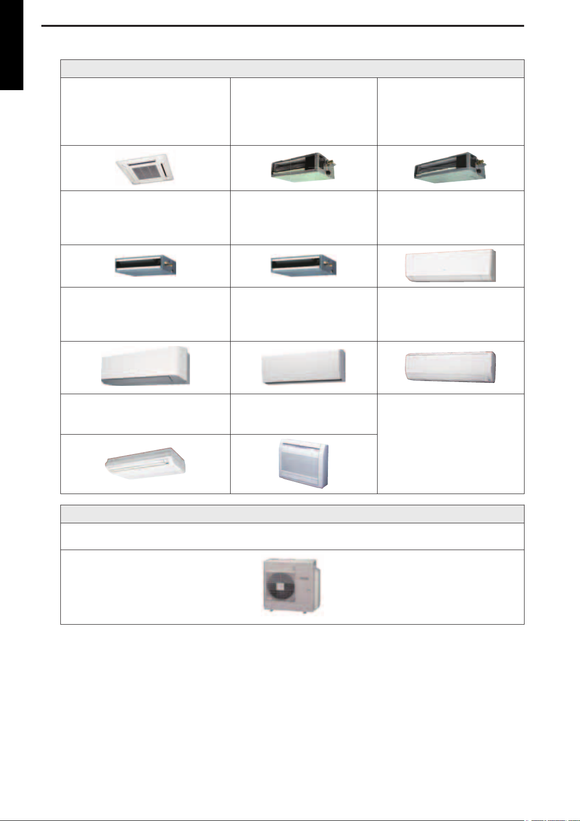
INDOOR
ARYG18LLTB ASYG07LMCA
ABYG14LVTA
ABYG18LVTB
AUYG07LVLA
AUYG09LVLA
AUYG12LVLB
AUYG14LVLB
AUYG18LVLB
ASYG09LMCA
ASYG12LMCA
ASYG14LMCA
AGYG09LVCA
AGYG12LVCA
AGYG14LVCA
ARYG07LSLAP
ARYG09LSLAP
ARYG12LSLAP
ARYG14LSLAP
ASYG07LMCE
ASYG09LMCE
ASYG12LMCE
ASYG14LMCE
ARYG18LSLAP ARYG07LLTA
ARYG09LLTA
ARYG12LLTB
ARYG14LLTB
ASYG07LUCA
ASYG09LUCA
ASYG12LUCA
ASYG14LUCA
ASYG18LFCA
ASYG24LFCA
ASYG24LFCC
OUTDOOR
AOYG36LBLA5
AOYG45LBLA6
DR_MU006EF_03
2017.05.22
Page 2

Notices:
• Product specifications and design are subject to change without notice for future improvement.
• For further details, please check with our authorized dealer.
Copyright © 2017 Fujitsu General Limited. All rights reserved.
Page 3

CONTENTS
Part 1. INDOOR UNIT....................................................................... 1
1. Model lineup ..............................................................................................2
1-1. Connectable indoor units to each outdoor unit............................................................ 3
1-2. Indoor unit connection patterns................................................................................... 4
2. Specifications............................................................................................9
2-1. Compact cassette type ............................................................................................... 9
2-2. Mini duct type............................................................................................................ 11
2-3. Slim duct type ........................................................................................................... 13
2-4. Wall mounted type .................................................................................................... 15
2-5. Floor/Ceiling type...................................................................................................... 19
2-6. Floor type.................................................................................................................. 20
3. Dimensions..............................................................................................21
3-1. Compact cassette type ............................................................................................. 21
3-2. Mini duct type............................................................................................................ 23
3-3. Slim duct type ........................................................................................................... 26
3-4. Wall mounted type .................................................................................................... 30
3-5. Floor/Ceiling type...................................................................................................... 38
3-6. Floor type.................................................................................................................. 40
4. Wiring diagrams ......................................................................................41
4-1. Compact cassette type ............................................................................................. 41
4-2. Mini duct type............................................................................................................ 42
4-3. Slim duct type ........................................................................................................... 43
4-4. Wall mounted type .................................................................................................... 44
4-5. Floor/Ceiling type...................................................................................................... 47
4-6. Floor type.................................................................................................................. 48
5. Air velocity and temperature distributions ........................................... 49
5-1. Compact cassette type ............................................................................................. 49
5-2. Mini duct type............................................................................................................ 57
5-3. Slim duct type ........................................................................................................... 67
5-4. Wall mounted type .................................................................................................... 77
5-5. Floor/Ceiling type...................................................................................................... 85
5-6. Floor type.................................................................................................................. 89
6. Fan performance .....................................................................................90
6-1. Mini duct type............................................................................................................ 90
6-2. Slim duct type ......................................................................................................... 100
7. Airflow....................................................................................................110
7-1. Compact cassette type ........................................................................................... 110
7-2. Mini duct type.......................................................................................................... 111
7-3. Slim duct type ......................................................................................................... 112
7-4. Wall mounted type .................................................................................................. 113
7-5. Floor/Ceiling type.................................................................................................... 115
Page 4

CONTENTS (continued)
7-6. Floor type................................................................................................................ 115
8. Noise level curve...................................................................................116
8-1. Compact cassette type ........................................................................................... 116
8-2. Mini duct type.......................................................................................................... 119
8-3. Slim duct type ......................................................................................................... 122
8-4. Wall mounted type .................................................................................................. 125
8-5. Floor/Ceiling type.................................................................................................... 130
8-6. Floor type................................................................................................................ 131
8-7. Sound level check point.......................................................................................... 133
9. Electrical characteristics ......................................................................136
10. Safety devices ....................................................................................... 137
11. External input and output..................................................................... 138
11-1.Compact cassette, slim duct, wall mounted, floor/ceiling, and floor types.............. 138
11-2.Mini duct type......................................................................................................... 148
12. Group connection ................................................................................. 154
12-1.Precautions on creating a group connection.......................................................... 155
12-2.Remote controller address setting procedure for wireless remote controllers........ 157
13. Remote controller .................................................................................158
13-1.Wireless remote controller (AR-RAH2E/AR-RAH1E)............................................. 158
13-2.Wireless remote controller (AR-REA2E/AR-REB1E) ............................................. 161
13-3.IR receiver kit with Wireless remote controller (UTY-LRHYM: Optional part)......... 164
13-4.IR receiver kit with Wireless remote controller (UTY-LBTYM: Optional part) ......... 167
13-5.Wired remote controller (UTY-RNNYM)................................................................. 170
13-6.Wired remote controller (UTY-RLRY) .................................................................... 175
13-7.Wired remote controller (UTY-RVNYM: Optional part)........................................... 178
13-8.Wired remote controller (UTY-RNRYZ*: Optional part).......................................... 187
13-9.Simple remote controller (UTY-RSNYM: Optional part) ......................................... 190
13-10.Simple remote controller (UTY-RSRY and UTY-RHRY: Optional parts).............. 195
14. Function settings .................................................................................. 198
14-1.Compact cassette, slim duct, and floor/ceiling types indoor unit (setting by DIP switch
and jumper wire)........................................................................................................ 198
14-2.Mini duct type indoor unit (setting by DIP switch)................................................... 200
14-3.Indoor unit (setting by wireless remote controller).................................................. 202
14-4.Indoor unit (setting by wired remote controller)...................................................... 223
14-5.Indoor unit (setting by simple remote controller) .................................................... 234
14-6.Function details...................................................................................................... 241
14-7.Wired remote controller (UTY-RNNYM)................................................................. 249
14-8.Wired remote controller (UTY-RVNYM)................................................................. 251
14-9.Wired remote controller (UTY-RLRY) .................................................................... 252
14-10.Wired remote controller (UTY-RNRYZ*) .............................................................. 253
14-11.Simple remote controller (UTY-RSNYM).............................................................. 254
15. Accessories ...........................................................................................255
15-1.Compact cassette type .......................................................................................... 255
Page 5

CONTENTS (continued)
15-2.Mini duct type......................................................................................................... 256
15-3.Slim duct type ........................................................................................................ 257
15-4.Wall mounted type ................................................................................................. 258
15-5.Floor/Ceiling type................................................................................................... 261
15-6.Floor type............................................................................................................... 262
16. Optional parts........................................................................................263
16-1.Controllers ............................................................................................................. 263
16-2.Cassette grille ........................................................................................................ 265
16-3.Others.................................................................................................................... 266
17. Indoor unit installation precautions .................................................... 270
17-1.Place where prohibited for use............................................................................... 270
17-2.Points to remember when installing ....................................................................... 271
Page 6

CONTENTS (continued)
Part 2. OUTDOOR UNIT (5 ROOMS TYPE) ................................ 273
1. Specifications........................................................................................274
2. Dimensions............................................................................................276
2-1. Model: AOYG36LBLA5........................................................................................... 276
3. Installation space ..................................................................................277
3-1. Model: AOYG36LBLA5........................................................................................... 277
4. Refrigerant circuit ................................................................................. 280
4-1. Model: AOYG36LBLA5........................................................................................... 280
5. Wiring diagram ......................................................................................281
5-1. Model: AOYG36LBLA5........................................................................................... 281
6. Capacity table........................................................................................282
6-1. Combinations.......................................................................................................... 282
6-2. Cooling capacity...................................................................................................... 287
6-3. Heating capacity ..................................................................................................... 302
7. Capacity compensation rate for pipe length and height difference..316
7-1. Model: AOYG36LBLA5........................................................................................... 316
8. Additional charge calculation .............................................................. 320
8-1. Model: AOYG36LBLA5........................................................................................... 320
9. Airflow....................................................................................................321
9-1. Model: AOYG36LBLA5........................................................................................... 321
10. Operation noise (sound pressure)....................................................... 322
10-1.Noise level curve.................................................................................................... 322
10-2.Sound level check point......................................................................................... 322
11. Electrical characteristics ......................................................................323
12. Safety devices ....................................................................................... 324
13. Function settings .................................................................................. 325
13-1.Setting methods..................................................................................................... 325
13-2.Outdoor unit low noise operation function (option)................................................. 328
13-3.Changing the current limit function......................................................................... 328
14. Check and test....................................................................................... 329
14-1.Check run .............................................................................................................. 329
14-2.Test run.................................................................................................................. 335
14-3.Error code .............................................................................................................. 336
14-4.Pump down............................................................................................................ 339
15. Accessories ...........................................................................................341
16. Optional parts........................................................................................342
17. Outdoor unit installation precautions ................................................. 343
17-1.Place where prohibited for use............................................................................... 343
17-2.Points to remember when installing ....................................................................... 343
Page 7

CONTENTS (continued)
Part 3. OUTDOOR UNIT (6 ROOMS TYPE) ................................ 345
1. Specifications........................................................................................346
2. Dimensions............................................................................................347
2-1. Model: AOYG45LBLA6........................................................................................... 347
3. Installation space ..................................................................................348
3-1. Model: AOYG45LBLA6........................................................................................... 348
4. Refrigerant circuit ................................................................................. 351
4-1. Model: AOYG45LBLA6........................................................................................... 351
5. Wiring diagram ......................................................................................352
5-1. Model: AOYG45LBLA6........................................................................................... 352
6. Capacity table........................................................................................353
6-1. Combinations.......................................................................................................... 353
6-2. Cooling capacity...................................................................................................... 361
6-3. Heating capacity ..................................................................................................... 376
7. Capacity compensation rate for pipe length and height difference..390
7-1. Model: AOYG45LBLA6........................................................................................... 390
8. Additional charge calculation .............................................................. 394
8-1. Model: AOYG45LBLA6........................................................................................... 394
9. Airflow....................................................................................................395
9-1. Model: AOYG45LBLA6........................................................................................... 395
10. Operation noise (sound pressure)....................................................... 396
10-1.Noise level curve.................................................................................................... 396
10-2.Sound level check point......................................................................................... 396
11. Electrical characteristics ......................................................................397
12. Safety devices ....................................................................................... 398
13. Function settings .................................................................................. 399
13-1.Setting methods..................................................................................................... 399
13-2.Outdoor unit low noise operation function (option)................................................. 402
13-3.Changing the current limit function......................................................................... 402
14. Check and test....................................................................................... 403
14-1.Check run .............................................................................................................. 403
14-2.Test run.................................................................................................................. 409
14-3.Error code .............................................................................................................. 410
14-4.Pump down............................................................................................................ 413
15. Accessories ...........................................................................................415
16. Optional parts........................................................................................416
17. Outdoor unit installation precautions ................................................. 417
17-1.Place where prohibited for use............................................................................... 417
17-2.Points to remember when installing ....................................................................... 417
Page 8

Page 9

Part 1. INDOOR UNIT
COMPACT CASSETTE TYPE:
AUYG07LVLA
AUYG09LVLA
ARYG07LSLAP
ARYG09LSLAP
ARYG07LLTA
ARYG09LLTA
ASYG07LUCA
ASYG09LUCA
ASYG12LUCA
ASYG14LUCA
AUYG12LVLB
AUYG14LVLB
MINI DUCT TYPE:
ARYG12LSLAP
ARYG14LSLAP
SLIM DUCT TYPE:
ARYG12LLTB
ARYG14LLTB
WALL MOUNTED TYPE:
ASYG07LMCA
ASYG09LMCA
ASYG12LMCA
ASYG14LMCA
ASYG07LMCE
ASYG09LMCE
ASYG12LMCE
ASYG14LMCE
FLOOR/CEILING TYPE:
AUYG18LVLB
ARYG18LSLAP
ARYG18LLTB
ASYG18LFCA
ASYG24LFCA
ASYG24LFCC
ABYG14LVTA ABYG18LVTB
FLOOR TYPE:
AGYG09LVCA AGYG12LVCA AGYG14LVCA
Page 10
1. Model lineup
MULTI TYPE
5, 6 ROOMS TYPE
AUYG07LVLA
AUYG09LVLA
AUYG12LVLB
AUYG14LVLB
AUYG18LVLB
Indoor unit
ARYG07LSLAP
ARYG09LSLAP
ARYG12LSLAP
ARYG14LSLAP
ARYG18LSLAP
ARYG07LLTA
ARYG09LLTA
ARYG12LLTB
ARYG14LLTB
ASYG07LMCE
ASYG09LMCE
ASYG12LMCE
ASYG14LMCE
ABYG14LVTA
ABYG18LVTB
ARYG18LLTB ASYG07LMCA
ASYG09LMCA
ASYG12LMCA
ASYG14LMCA
ASYG07LUCA
ASYG09LUCA
ASYG12LUCA
ASYG14LUCA
AGYG09LVCA
AGYG12LVCA
AGYG14LVCA
ASYG18LFCA
ASYG24LFCA
ASYG24LFCC
Outdoor unit
AOYG36LBLA5
AOYG45LBLA6
- 2 -
Page 11

1-1. Connectable indoor units to each outdoor unit
●: Connectable / -: Not connectable
Compact cassette Mini duct
Outdoor unit
Btu class 07 09 12 14 18 07 09 12 14 18
kW class 2.0 2.5 3.5 4.0 5.0 2.0 2.5 3.5 4.0 5.0
AOYG36LBLA5 ● ● ● ● ● ● ● ● ● ●
AOYG45LBLA6 ● ● ● ● ● ● ● ● ● ●
Outdoor unit
Btu class 07 09 12 14 18 07 09 12 14
kW class 2.0 2.5 3.5 4.0 5.0 2.0 2.5 3.5 4.0
AOYG36LBLA5 ● ● ● ● ● ● ● ● ●
AOYG45LBLA6 ● ● ● ● ● ● ● ● ●
Outdoor unit
Btu class 18 24 14 18 09 12 14
kW class 5.0 7.0 4.0 5.0 2.5 3.5 4.0
AOYG36LBLA5 ● ● ● ● ● ● ●
AOYG45LBLA6 ● ● ● ● ● ● ●
AUYG07—09LVLA
AUYG12—18LVLB
ARYG07—09LLTA
ARYG12—18LLTB
Wall mounted
LF
ASYG18LFCA
ASYG24LFCA
ASYG24LFCC
ARYG07—18LSLAP
Slim duct Wall mounted
LU/LM
ASYG07—14LMCA
ASYG07—14LMCE
ASYG07—14LUCA
Floor/Ceiling Floor
ABYG14LVTA
ABYG18LVTB
AGYG09—14LVCA
MULTI TYPE
5, 6 ROOMS TYPE
- 3 -
Page 12

1-2. Indoor unit connection patterns
¢ 5 rooms
MULTI TYPE
5, 6 ROOMS TYPE
AOYG36LBLA5
No. Room 1 Room 2 Room 3 Room 4 Room 5 Total
1 7 24 — — — 31
2 9 24 — — — 33
3 12 24 — — — 36
4 14 24 — — — 38
5 18 18 — — — 36
6 18 24 — — — 42
7 24 24 — — — 48
8 7 7 14 — — 28
9 7 7 18 — — 32
10 7 7 24 — — 38
11 7 9 12 — — 28
12 7 9 14 — — 30
13 7 9 18 — — 34
14 7 9 24 — — 40
15 7 12 12 — — 31
16 7 12 14 — — 33
17 7 12 18 — — 37
18 7 12 24 — — 43
19 7 14 14 — — 35
20 7 14 18 — — 39
21 7 14 24 — — 45
22 7 18 18 — — 43
23 7 18 24 — — 49
24 9 9 9 — — 27
25 9 9 12 — — 30
26 9 9 14 — — 32
27 9 9 18 — — 36
28 9 9 24 — — 42
29 9 12 12 — — 33
30 9 12 14 — — 35
31 9 12 18 — — 39
32 9 12 24 — — 45
33 9 14 14 — — 37
34 9 14 18 — — 41
35 9 14 24 — — 47
36 9 18 18 — — 45
37 9 18 24 — — 51
38 12 12 12 — — 36
39 12 12 14 — — 38
40 12 12 18 — — 42
41 12 12 24 — — 48
42 12 14 14 — — 40
43 12 14 18 — — 44
44 12 14 24 — — 50
45 12 18 18 — — 48
46 12 18 24 — — 54
47 14 14 14 — — 42
48 14 14 18 — — 46
49 14 14 24 — — 52
50 14 18 18 — — 50
51 18 18 18 — — 54
52 7 7 7 7 — 28
53 7 7 7 9 — 30
54 7 7 7 12 — 33
55 7 7 7 14 — 35
56 7 7 7 18 — 39
57 7 7 7 24 — 45
58 7 7 9 9 — 32
59 7 7 9 12 — 35
60 7 7 9 14 — 37
61 7 7 9 18 — 41
62 7 7 9 24 — 47
63 7 7 12 12 — 38
64 7 7 12 14 — 40
65 7 7 12 18 — 44
66 7 7 12 24 — 50
67 7 7 14 14 — 42
68 7 7 14 18 — 46
69 7 7 14 24 — 52
70 7 7 18 18 — 50
71 7 9 9 9 — 34
72 7 9 9 12 — 37
73 7 9 9 14 — 39
74 7 9 9 18 — 43
75 7 9 9 24 — 49
76 7 9 12 12 — 40
77 7 9 12 14 — 42
78 7 9 12 18 — 46
79 7 9 12 24 — 52
80 7 9 12 14 — 42
81 7 9 14 18 — 48
82 7 9 14 24 — 54
83 7 9 18 18 — 52
84 7 12 12 12 — 43
- 4 -
Page 13
AOYG36LBLA5
No. Room 1 Room 2 Room 3 Room 4 Room 5 Total
85 7 12 12 14 — 45
86 7 12 12 18 — 49
87 7 12 14 14 — 47
88 7 12 14 18 — 51
89 7 14 14 14 — 49
90 7 14 14 18 — 53
91 9 9 9 9 — 36
92 9 9 9 12 — 39
93 9 9 9 14 — 41
94 9 9 9 18 — 45
95 9 9 9 24 — 51
96 9 9 12 12 — 42
97 9 9 12 14 — 44
98 9 9 12 18 — 48
99 9 9 12 24 — 54
100 9 9 14 14 — 46
101 9 9 14 18 — 50
102 9 9 18 18 — 54
103 9 12 12 12 — 45
104 9 12 12 14 — 47
105 9 12 12 18 — 51
106 9 12 14 14 — 49
107 9 12 14 18 — 53
108 9 14 14 14 — 51
109 12 12 12 12 — 48
110 12 12 12 14 — 50
111 12 12 12 18 — 54
112 12 12 14 14 — 52
113 12 14 14 14 — 54
114 7 7 7 7 7 35
115 7 7 7 7 9 37
116 7 7 7 7 12 40
117 7 7 7 7 14 42
118 7 7 7 7 18 46
119 7 7 7 7 24 52
120 7 7 7 9 9 39
121 7 7 7 9 12 42
122 7 7 7 9 14 44
123 7 7 7 9 18 48
124 7 7 7 9 24 54
125 7 7 7 12 12 45
126 7 7 7 12 14 47
127 7 7 7 12 18 51
128 7 7 7 14 14 49
129 7 7 7 14 18 53
130 7 7 9 9 9 41
131 7 7 9 9 12 44
132 7 7 9 9 14 46
133 7 7 9 9 18 50
134 7 7 9 12 12 47
135 7 7 9 12 14 49
136 7 7 9 12 18 53
137 7 7 9 14 14 51
138 7 7 12 12 12 50
139 7 7 12 12 14 52
140 7 7 12 14 14 54
141 7 9 9 9 9 43
142 7 9 9 9 12 46
143 7 9 9 9 14 48
144 7 9 9 9 18 52
145 7 9 9 12 12 49
146 7 9 9 12 14 51
147 7 9 9 14 14 53
148 7 9 12 12 12 52
149 7 9 12 12 14 54
150 9 9 9 9 9 45
151 9 9 9 9 12 48
152 9 9 9 9 14 50
153 9 9 9 9 18 54
154 9 9 9 12 12 51
155 9 9 9 12 14 53
156 9 9 12 12 12 54
MULTI TYPE
5, 6 ROOMS TYPE
NOTE:
7: 7,000Btu/h, 9: 9,000Btu/h, 12: 12,000Btu/h, 14: 14,000Btu/h, 18: 18,000Btu/h,
24: 24,000Btu/h
- 5 -
Page 14
¢ 6 rooms
MULTI TYPE
5, 6 ROOMS TYPE
AOYG45LBLA6
No. Room 1 Room 2 Room 3 Room 4 Room 5 Room 6 Total
1 12 24 — — — — 36
2 14 24 — — — — 38
3 18 18 — — — — 36
4 18 24 — — — — 42
5 24 24 — — — — 48
6 7 7 24 — — — 38
7 7 9 18 — — — 34
8 7 9 24 — — — 40
9 7 12 18 — — — 37
10 7 12 24 — — — 43
11 7 14 14 — — — 35
12 7 14 18 — — — 39
13 7 14 24 — — — 45
14 7 18 18 — — — 43
15 7 18 24 — — — 49
16 7 24 24 — — — 55
17 9 9 18 — — — 36
18 9 9 24 — — — 42
19 9 12 14 — — — 35
20 9 12 18 — — — 39
21 9 12 24 — — — 45
22 9 14 14 — — — 37
23 9 14 18 — — — 41
24 9 14 24 — — — 47
25 9 18 18 — — — 45
26 9 18 24 — — — 51
27 9 24 24 — — — 57
28 12 12 12 — — — 36
29 12 12 14 — — — 38
30 12 12 18 — — — 42
31 12 12 24 — — — 48
32 12 14 14 — — — 40
33 12 14 18 — — — 44
34 12 14 24 — — — 50
35 12 18 18 — — — 48
36 12 18 24 — — — 54
37 12 24 24 — — — 60
38 14 14 14 — — — 42
39 14 14 18 — — — 46
40 14 14 24 — — — 52
41 14 18 18 — — — 50
42 14 18 24 — — — 56
43 14 24 24 — — — 62
44 18 18 18 — — — 54
45 18 18 24 — — — 60
46 7 7 7 14 — — 35
47 7 7 7 18 — — 39
48 7 7 7 24 — — 45
49 7 7 9 12 — — 35
50 7 7 9 14 — — 37
51 7 7 9 18 — — 41
52 7 7 9 24 — — 47
53 7 7 12 12 — — 38
54 7 7 12 14 — — 40
55 7 7 12 18 — — 44
56 7 7 12 24 — — 50
57 7 7 14 14 — — 42
58 7 7 14 18 — — 46
59 7 7 14 24 — — 52
60 7 7 18 18 — — 50
61 7 7 18 24 — — 56
62 7 7 24 24 — — 62
63 7 9 9 9 — — 34
64 7 9 9 12 — — 37
65 7 9 9 14 — — 39
66 7 9 9 18 — — 43
67 7 9 9 24 — — 49
68 7 9 12 12 — — 40
69 7 9 12 14 — — 42
70 7 9 12 18 — — 46
71 7 9 12 24 — — 52
72 7 9 14 14 — — 44
73 7 9 14 18 — — 48
74 7 9 14 24 — — 54
75 7 9 18 18 — — 52
76 7 9 18 24 — — 58
77 7 12 12 12 — — 43
78 7 12 12 14 — — 45
79 7 12 12 18 — — 49
80 7 12 12 24 — — 55
81 7 12 14 14 — — 47
82 7 12 14 18 — — 51
83 7 12 14 24 — — 57
84 7 12 18 18 — — 55
85 7 12 18 24 — — 61
86 7 14 14 14 — — 49
87 7 14 14 18 — — 53
88 7 14 14 24 — — 59
- 6 -
Page 15
AOYG45LBLA6
No. Room 1 Room 2 Room 3 Room 4 Room 5 Room 6 Total
89 7 14 18 18 — — 57
90 7 18 18 18 — — 61
91 9 9 9 9 — — 36
92 9 9 9 12 — — 39
93 9 9 9 14 — — 41
94 9 9 9 18 — — 45
95 9 9 9 24 — — 51
96 9 9 12 12 — — 42
97 9 9 12 14 — — 44
98 9 9 12 18 — — 48
99 9 9 12 24 — — 54
100 9 9 14 14 — — 46
101 9 9 14 18 — — 50
102 9 9 14 24 — — 56
103 9 9 18 18 — — 54
104 9 9 18 24 — — 60
105 9 12 12 12 — — 45
106 9 12 12 14 — — 47
107 9 12 12 18 — — 51
108 9 12 12 24 — — 57
109 9 12 14 14 — — 49
110 9 12 14 18 — — 53
111 9 12 14 24 — — 59
112 9 12 18 18 — — 57
113 9 14 14 14 — — 51
114 9 14 14 18 — — 55
115 9 14 14 24 — — 61
116 9 14 18 18 — — 59
117 12 12 12 12 — — 48
118 12 12 12 14 — — 50
119 12 12 12 18 — — 54
120 12 12 12 24 — — 60
121 12 12 14 14 — — 52
122 12 12 14 18 — — 56
123 12 12 14 24 — — 62
124 12 12 18 18 — — 60
125 12 14 14 14 — — 54
126 12 14 14 18 — — 58
127 12 14 18 18 — — 62
128 7 7 7 7 7 — 35
129 7 7 7 7 9 — 37
130 7 7 7 7 12 — 40
131 7 7 7 7 14 — 42
132 7 7 7 7 18 — 46
133 7 7 7 7 24 — 52
134 7 7 7 9 9 — 39
135 7 7 7 9 12 — 42
136 7 7 7 9 14 — 44
137 7 7 7 9 18 — 48
138 7 7 7 9 24 — 54
139 7 7 7 12 12 — 45
140 7 7 7 12 14 — 47
141 7 7 7 12 18 — 51
142 7 7 7 12 24 — 57
143 7 7 7 14 14 — 49
144 7 7 7 14 18 — 53
145 7 7 7 14 24 — 59
146 7 7 7 18 18 — 57
147 7 7 9 9 9 — 41
148 7 7 9 9 12 — 44
149 7 7 9 9 14 — 46
150 7 7 9 9 18 — 50
151 7 7 9 9 24 — 56
152 7 7 9 12 12 — 47
153 7 7 9 12 14 — 49
154 7 7 9 12 18 — 53
155 7 7 9 12 24 — 59
156 7 7 9 14 14 — 51
157 7 7 9 14 18 — 55
158 7 7 9 14 24 — 61
159 7 7 9 18 18 — 59
160 7 7 12 12 12 — 50
161 7 7 12 12 14 — 52
162 7 7 12 12 18 — 56
163 7 7 12 12 24 — 62
164 7 7 12 14 14 — 54
165 7 7 12 14 18 — 58
166 7 7 12 18 18 — 62
167 7 7 14 14 14 — 56
168 7 7 14 14 18 — 60
169 7 9 9 9 9 — 43
170 7 9 9 9 12 — 46
171 7 9 9 9 14 — 48
172 7 9 9 9 18 — 52
173 7 9 9 9 24 — 58
174 7 9 9 12 12 — 49
175 7 9 9 12 14 — 51
176 7 9 9 12 18 — 55
177 7 9 9 12 24 — 61
178 7 9 9 14 14 — 53
179 7 9 9 14 18 — 57
MULTI TYPE
5, 6 ROOMS TYPE
- 7 -
Page 16

MULTI TYPE
5, 6 ROOMS TYPE
AOYG45LBLA6
No. Room 1 Room 2 Room 3 Room 4 Room 5 Room 6 Total
180 7 9 9 18 18 — 61
181 7 9 12 12 12 — 52
182 7 9 12 12 14 — 54
183 7 9 12 12 18 — 58
184 7 9 12 14 14 — 56
185 7 9 12 14 18 — 60
186 7 9 14 14 14 — 58
187 7 9 14 14 18 — 62
188 7 12 12 12 12 — 55
189 7 12 12 12 14 — 57
190 7 12 12 12 18 — 61
191 7 12 12 14 14 — 59
192 7 12 14 14 14 — 61
193 9 9 9 9 9 — 45
194 9 9 9 9 12 — 48
195 9 9 9 9 14 — 50
196 9 9 9 9 18 — 54
197 9 9 9 9 24 — 60
198 9 9 9 12 12 — 51
199 9 9 9 12 14 — 53
200 9 9 9 12 18 — 57
201 9 9 9 14 14 — 55
202 9 9 9 14 18 — 59
203 9 9 12 12 12 — 54
204 9 9 12 12 14 — 56
205 9 9 12 12 18 — 60
206 9 9 12 14 14 — 58
207 9 9 12 14 18 — 62
208 9 9 14 14 14 — 60
209 9 12 12 12 12 — 57
210 9 12 12 12 14 — 59
211 9 12 12 14 14 — 61
212 12 12 12 12 12 — 60
213 12 12 12 12 14 — 62
214 7 7 7 7 7 7 42
215 7 7 7 7 7 9 44
216 7 7 7 7 7 12 47
217 7 7 7 7 7 14 49
218 7 7 7 7 7 18 53
219 7 7 7 7 7 24 59
220 7 7 7 7 9 9 46
221 7 7 7 7 9 12 49
222 7 7 7 7 9 14 51
223 7 7 7 7 9 18 55
224 7 7 7 7 9 24 61
225 7 7 7 7 12 12 52
226 7 7 7 7 12 14 54
227 7 7 7 7 12 18 58
228 7 7 7 7 14 14 56
229 7 7 7 7 14 18 60
230 7 7 7 9 9 9 48
231 7 7 7 9 9 12 51
232 7 7 7 9 9 14 53
233 7 7 7 9 9 18 57
234 7 7 7 9 12 12 54
235 7 7 7 9 12 14 56
236 7 7 7 9 12 18 60
237 7 7 7 9 14 14 58
238 7 7 7 12 12 12 57
239 7 7 7 12 12 14 59
240 7 7 7 12 14 14 61
241 7 7 9 9 9 9 50
246 7 7 9 9 9 12 53
247 7 7 9 9 9 14 55
248 7 7 9 9 9 18 59
242 7 7 9 9 12 12 56
243 7 7 9 9 12 14 58
244 7 7 9 9 12 18 62
245 7 7 9 9 14 14 60
249 7 7 9 12 12 12 59
250 7 7 9 12 12 14 61
251 7 7 12 12 12 12 62
252 7 9 9 9 9 9 52
253 7 9 9 9 9 12 55
254 7 9 9 9 9 14 57
255 7 9 9 9 12 12 58
256 7 9 9 9 12 14 60
257 7 9 9 12 12 12 61
258 9 9 9 9 9 9 54
259 9 9 9 9 9 12 57
260 9 9 9 9 12 12 60
NOTE:
7: 7,000Btu/h, 9: 9,000Btu/h, 12: 12,000Btu/h, 14: 14,000Btu/h, 18: 18,000Btu/h,
24: 24,000Btu/h
- 8 -
Page 17

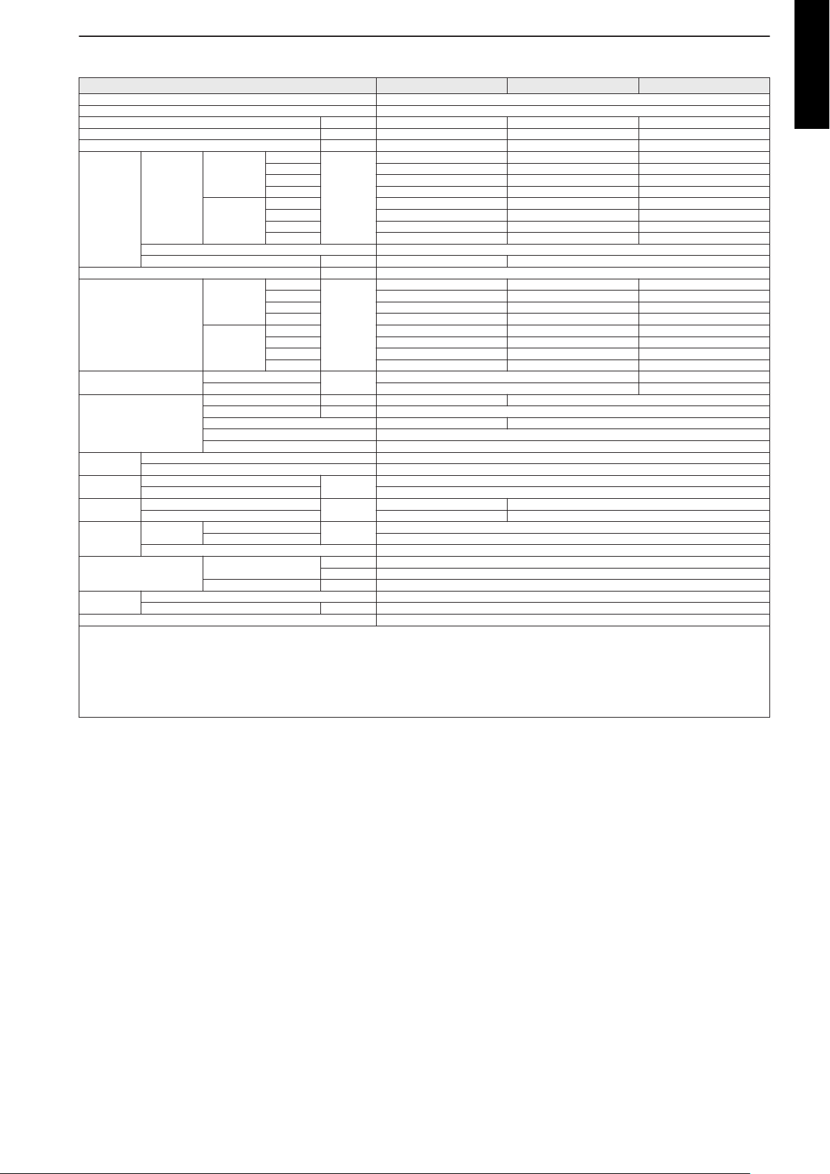
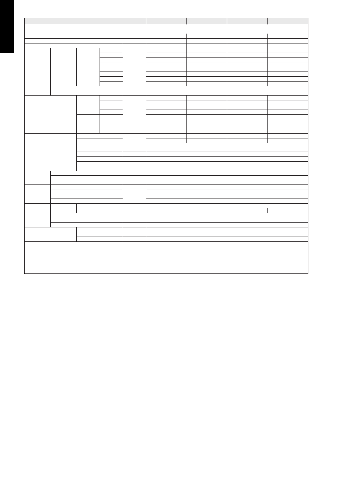
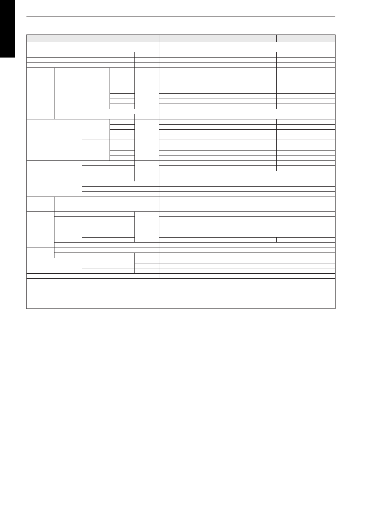
2. Specifications
2-1. Compact cassette type
Model name AUYG07LVLA AUYG09LVLA AUYG12LVLB
Power supply 1Ø 230 V ~50 Hz
Available voltage range 198—264 V
Capacity kW class 2.0 2.5 3.5
Input power W 18 23
Running current A 0.15 0.19
Cooling
Fan
Sound pressure level *
Sound power level
Heat exchanger type
Dimensions
(H × W × D)
Weight
Connection
pipe
Operation range
Drain hose
Cassette grille
Remote controller type Wireless (Wired [option])
NOTES:
• The protective function might work when using it outside the operation range.
• *: Sound pressure level:
– These are the measured values in the manufacturer’s anechoic chamber.
– Because of the surrounding sound environment, the sound levels measured in actual installation conditions might be higher than the specified values here.
Airflow rate
Heating
Type × Q'ty Turbo fan × 1
Motor output W 54
Cooling
Heating
Cooling
Heating 47 49
Dimensions (H × W × D) mm 210 × 1,310 × 13.3 + 210 × 1,250 × 13.3
Fin pitch mm 1.2
Rows × Stages 2 × 10
Pipe type Copper tube
Net
Gross 265 × 730 × 625
Net
Gross 18
Size
Method Flare
Material Hard PVC
Size mm Ø 25 (I.D.), Ø 32 (O.D.)
Fin type Aluminum
Liquid
Gas Ø9.52 (Ø3/8)
Cooling
Heating °C 16 to 30
Model name UTG-UFYD-W
Material PS
Color
Dimensions
(H × W × D)
Weight
HIGH
MED 490 530
LOW 440 470
QUIET 390 410
HIGH 540 610
MED 490 530
LOW 440 470
QUIET 390 410
HIGH
MED 31 33
LOW 29 31
QUIET 27 28
HIGH 34 37
MED 32 33
LOW 29 31
QUIET 27 28
Net
Gross 120 × 765 × 755
Net
Gross 4.5
m3/h
dB (A)
dB (A)
mm
kg
mm (in)
°C 18 to 32
%RH 80 or less
mm
kg
540 610
33 37
46 49
245 × 570 × 570
15
Ø6.35 (Ø1/4)
White
(Approximate color of Munsell N 9.25/)
49 × 700 × 700
2.6
MULTI TYPE
5, 6 ROOMS TYPE
- 9 -
Page 18

Model name AUYG14LVLB AUYG18LVLB
Power supply 1Ø 230 V ~50 Hz
Available voltage range 198—264 V
Capacity kW class 4.0 5.0
Input power W 28 39
Running current A 0.22 0.30
MULTI TYPE
5, 6 ROOMS TYPE
Fan
Sound pressure level *
Sound power level
Heat exchanger type
Dimensions
(H × W × D)
Weight
Connection
pipe
Operation range
Drain hose
Cassette grille
Remote controller type Wireless (Wired [option])
NOTES:
• The protective function might work when using it outside the operation range.
• *: Sound pressure level:
– These are the measured values in the manufacturer’s anechoic chamber.
– Because of the surrounding sound environment, the sound levels measured in actual installation conditions might be higher than the specified values here.
HIGH
Cooling
Airflow rate
Heating
Type × Q'ty Turbo fan × 1
Motor output W 54
Cooling
Heating
Cooling
Heating 52 56
Dimensions (H × W × D) mm 210 × 1,310 × 13.3 + 210 × 1,250 × 13.3
Fin pitch mm 1.2
Rows × Stages 2 × 10
Pipe type Copper tube
Net
Gross 265 × 730 × 625
Net
Gross 18
Size
Method Flare
Material Hard PVC
Size mm Ø 25 (I.D.), Ø 32 (O.D.)
Fin type Aluminum
Liquid
Gas Ø12.70 (Ø1/2)
Cooling
Heating °C 16 to 30
Model name UTG-UFYD-W
Material PS
Color
Dimensions
(H × W × D)
Weight
MED 580 610
LOW 490 520
QUIET 410 410
HIGH 700 800
MED 620 710
LOW 550 600
QUIET 430 450
HIGH
MED 35 37
LOW 32 33
QUIET 29 29
HIGH 40 44
MED 37 40
LOW 34 37
QUIET 29 30
Net
Gross 120 × 765 × 755
Net
Gross 4.5
m3/h
dB (A)
dB (A)
mm
kg
mm (in)
°C 18 to 32
%RH 80 or less
mm
kg
680 750
40 42
52 54
245 × 570 × 570
15
Ø6.35 (Ø1/4)
White
(Approximate color of Munsell N 9.25/)
49 × 700 × 700
2.6
- 10 -
Page 19

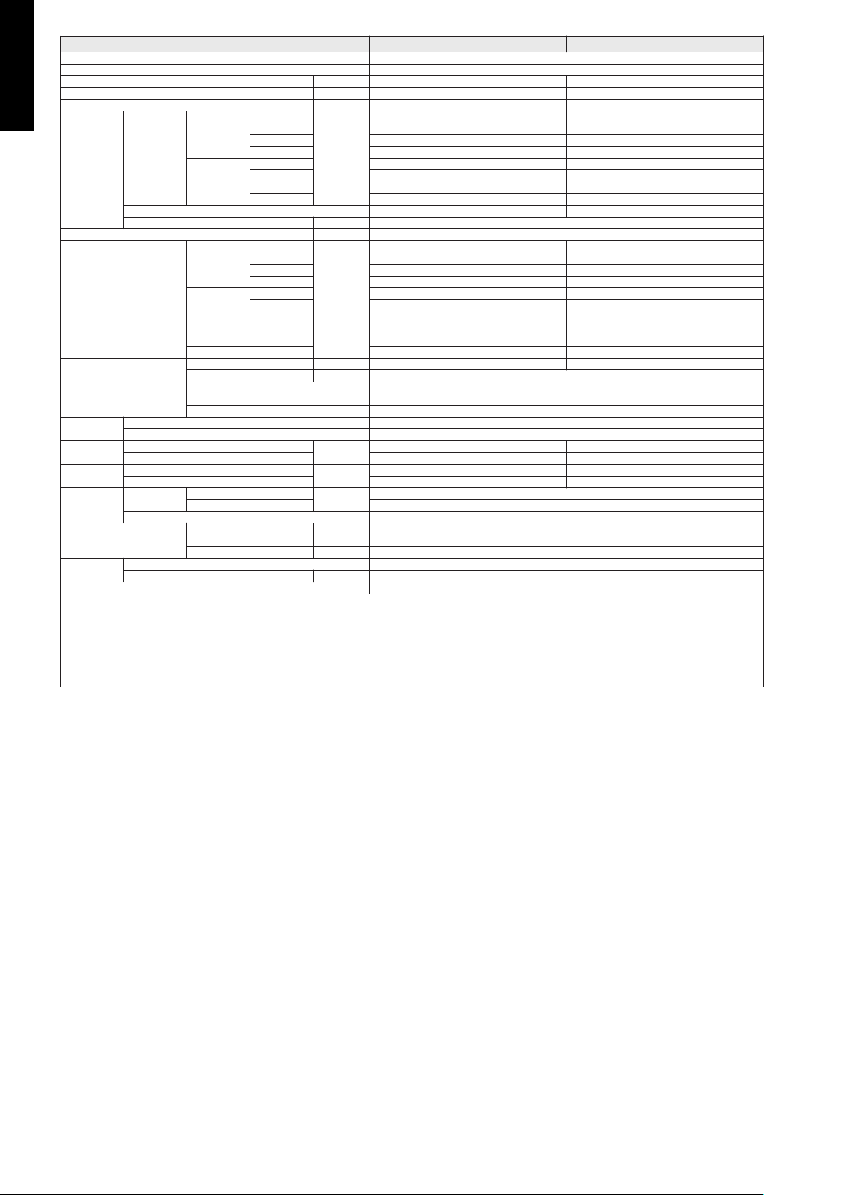
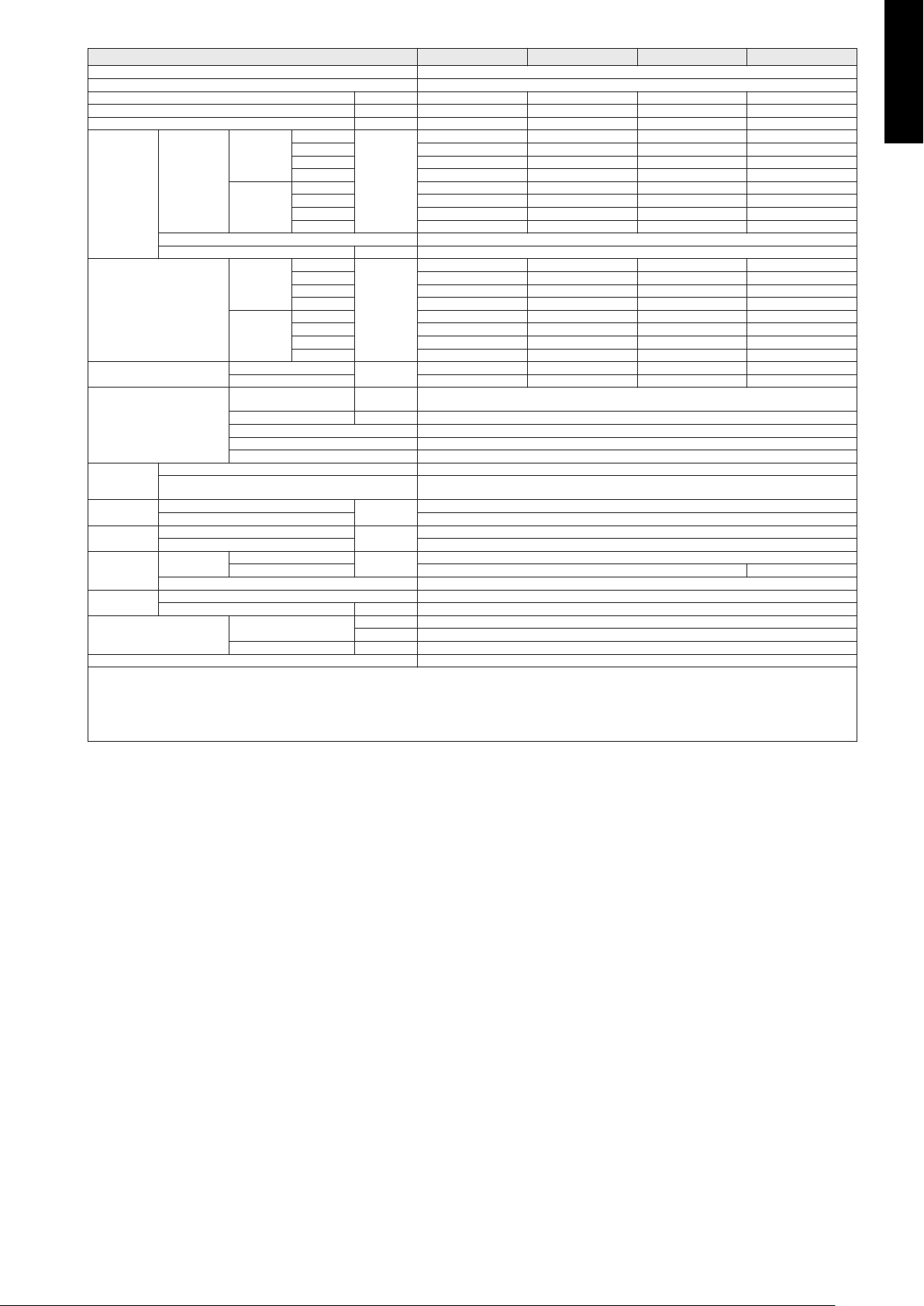
2-2. Mini duct type
Model name ARYG07LSLAP ARYG09LSLAP ARYG12LSLAP
Power supply 1Ø 230 V ~50 Hz
Available voltage range 198—264 V
Capacity kW class 2.0 2.5 3.5
Input power Fan
Running current A 0.29 0.33 0.38
Cooling
Fan
Recommended static pressure Pa 0 to 30
Sound pressure level *
Sound power level
Heat exchanger type
Enclosure
Dimensions
(H × W × D)
Weight
Connection
pipe
Operation range
Drain hose
Remote controller type Wired (Wireless [option])
NOTES:
• Values mentioned in the table are based on the following conditions:
– Static pressure: 10 Pa
• The protective function might work when using it outside the operation range.
• *: Sound pressure level:
– These are the measured values in the manufacturer’s anechoic chamber.
– Because of the surrounding sound environment, the sound levels measured in actual installation conditions might be higher than the specified values here.
Airflow rate
Heating
Type × Q'ty Sirocco fan × 2
Motor output W 75
Cooling
Heating
Cooling
Heating 53 56 57
Dimensions (H × W × D) mm 336 × 490 × 26.6
Fin pitch mm 1.3
Rows × Stages 2 × 16
Pipe type Copper tube
Material Steel sheet
Color —
Net
Gross 250 × 930 × 580
Net
Gross 19.5
Size
Method Flare
Material Hard PVC
Size mm Ø 25 (I.D.), Ø 32 (O.D.)
Fin type Aluminum
Liquid
Gas Ø9.52 (Ø3/8)
Cooling
Heating °C 16 to 30
HIGH
MED 23 23 26
LOW 20 20 22
QUIET 18 18 18
HIGH
MED 440 450 490
LOW 390 400 430
QUIET 360 360 360
HIGH 550 600 650
MED 440 450 490
LOW 390 400 430
QUIET 360 360 360
HIGH
MED 26 26 27
LOW 24 24 25
QUIET 23 23 23
HIGH 29 29 31
MED 26 26 27
LOW 24 24 25
QUIET 23 23 23
W
m3/h
dB (A)
dB (A)
mm
kg
mm (in)
°C 18 to 32
%RH 80 or less
33 40 47
550 600 650
29 29 31
52 54 55
198 × 700 × 450
15.5
Ø6.35 (Ø1/4)
MULTI TYPE
5, 6 ROOMS TYPE
- 11 -
Page 20

Model name ARYG14LSLAP ARYG18LSLAP
Power supply 1Ø 230 V ~50 Hz
Available voltage range 198—264 V
Capacity kW class 4.0 5.0
Input power Fan
MULTI TYPE
5, 6 ROOMS TYPE
Running current A 0.58 0.49
Fan
Recommended static pressure Pa 0 to 50
Sound pressure level *
Sound power level
Heat exchanger type
Enclosure
Dimensions
(H × W × D)
Weight
Connection
pipe
Operation range
Drain hose
Remote controller type Wired (Wireless [option])
NOTES:
• Values mentioned in the table are based on the following conditions:
– Static pressure: 15 Pa
• The protective function might work when using it outside the operation range.
• *: Sound pressure level:
– These are the measured values in the manufacturer’s anechoic chamber.
– Because of the surrounding sound environment, the sound levels measured in actual installation conditions might be higher than the specified values here.
HIGH
MED 44 38
LOW 30 22
QUIET 18 19
HIGH
Cooling
Airflow rate
Heating
Type × Q'ty Sirocco fan × 2 Sirocco fan × 3
Motor output W 75 80
Cooling
Heating
Cooling
Heating 62 59
Dimensions (H × W × D) mm 336 × 490 × 26.6 336 × 690 × 26.6
Fin pitch mm 1.3
Rows × Stages 2 × 16
Pipe type Copper tube
Material Steel sheet
Color —
Net
Gross 250 × 930 × 580 250 × 1,130 × 580
Net
Gross 19.5 23.0
Size
Method Flare
Material Hard PVC
Size mm Ø 25 (I.D.), Ø 32 (O.D.)
Fin type Aluminum
Liquid
Gas Ø12.7 (Ø1/2)
Cooling
Heating °C 16 to 30
MED 640 750
LOW 530 540
QUIET 360 480
HIGH 800 940
MED 640 750
LOW 530 540
QUIET 360 480
HIGH
MED 30 29
LOW 27 26
QUIET 23 23
HIGH 35 33
MED 30 29
LOW 27 26
QUIET 23 23
W
m3/h
dB (A)
dB (A)
mm
kg
mm (in)
°C 18 to 32
%RH 80 or less
72 63
800 940
35 33
60 58
198 × 700 × 450 198 × 900 × 450
15.5 18.5
Ø6.35 (Ø1/4)
- 12 -
Page 21
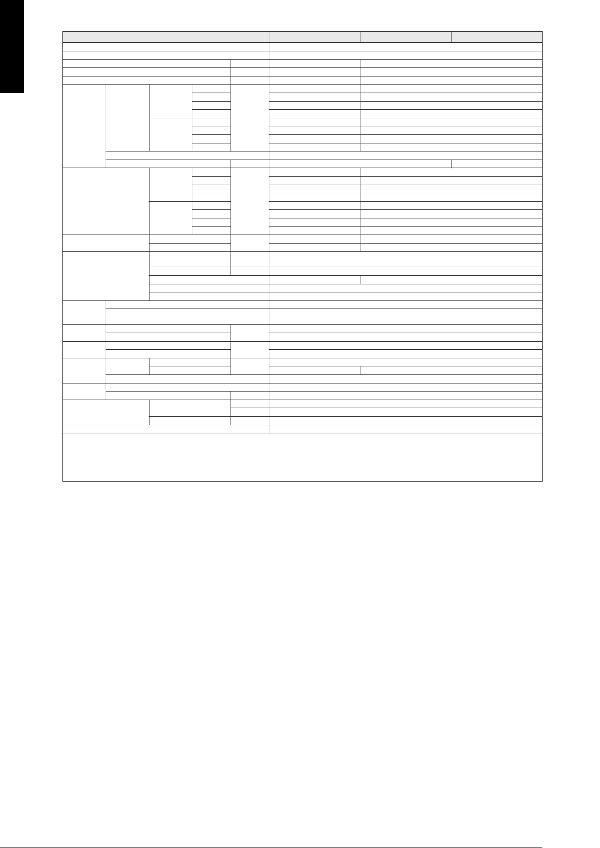
2-3. Slim duct type
Model name ARYG07LLTA ARYG09LLTA ARYG12LLTB
Power supply 1Ø 230 V ~50 Hz
Available voltage range 198—264 V
Capacity kW class 2.0 2.5 3.5
Input power W 33 49 58
Running current A 0.33 0.30 0.35
Cooling
Fan
Recommended static pressure Pa 0 to 90
Sound pressure level *
Sound power level
Heat exchanger type
Enclosure
Dimensions
(H × W × D)
Weight
Connection
pipe
Operation range
Drain hose
Remote controller type Wired (Wireless [option])
NOTES:
• Values mentioned in the table are based on the following conditions:
– Static pressure: 25 Pa
• The protective function might work when using it outside the operation range.
• *: Sound pressure level:
– These are the measured values in the manufacturer’s anechoic chamber.
– Because of the surrounding sound environment, the sound levels measured in actual installation conditions might be higher than the specified values here.
Airflow rate
Heating
Type × Q'ty Sirocco fan × 2
Motor output W 80 81
Cooling
Heating
Cooling
Heating 57 58
Dimensions (H × W × D) mm 294 × 500 × 26.6 294 × 500 × 39.9
Fin pitch mm 1.3
Rows × Stages 2 × 14 3 × 14
Pipe type Copper tube
Material Steel sheet
Color —
Net
Gross 274 × 945 × 772
Net
Gross 21 23
Size
Method Flare
Material Hard PVC
Size mm Ø 25 (I.D.), Ø 32 (O.D.)
Fin type Aluminum
Liquid
Gas Ø9.52 (Ø3/8)
Cooling
Heating °C 16 to 30
HIGH
MED 490 550 600
LOW 470 500 550
QUIET 440 450 480
HIGH 550 600 650
MED 490 550 600
LOW 470 500 550
QUIET 440 450 480
HIGH
MED 26 27 28
LOW 25 26 27
QUIET 24 25 26
HIGH 28 28 29
MED 26 26 28
LOW 25 25 27
QUIET 24 24 24
m3/h
dB (A)
dB (A)
mm
kg
mm (in)
°C 18 to 32
%RH 80 or less
550 600 650
28 28 29
57 58
198 × 700 × 620
17 19
Ø6.35 (Ø1/4)
MULTI TYPE
5, 6 ROOMS TYPE
- 13 -
Page 22
Model name ARYG14LLTB ARYG18LLTB
Power supply 1Ø 230 V ~50 Hz
Available voltage range 198—264 V
Capacity kW class 4.0 5.0
Input power W 76 73
Running current A 0.51 0.44
MULTI TYPE
5, 6 ROOMS TYPE
Fan
Recommended static pressure Pa 0 to 90
Sound pressure level *
Sound power level
Heat exchanger type
Enclosure
Dimensions
(H × W × D)
Weight
Connection
pipe
Operation range
Drain hose
Remote controller type Wired (Wireless [option])
NOTES:
• Values mentioned in the table are based on the following conditions:
– Static pressure: 25 Pa
• The protective function might work when using it outside the operation range.
• *: Sound pressure level:
– These are the measured values in the manufacturer’s anechoic chamber.
– Because of the surrounding sound environment, the sound levels measured in actual installation conditions might be higher than the specified values here.
HIGH
Cooling
Airflow rate
Heating
Type × Q'ty Sirocco fan × 2 Sirocco fan × 3
Motor output W 81
Cooling
Heating
Cooling
Heating 61 59
Dimensions (H × W × D) mm 294 × 500 × 39.9 294 × 700 × 39.9
Fin pitch mm 1.3
Rows × Stages 3 × 14
Pipe type Copper tube
Material Steel sheet
Color —
Net
Gross 274 × 945 × 772 274 × 1,145 × 772
Net
Gross 23 27
Size
Method Flare
Material Hard PVC
Size mm Ø 25 (I.D.), Ø 32 (O.D.)
Fin type Aluminum
Liquid
Gas Ø12.70 (Ø1/2)
Cooling
Heating °C 16 to 30
MED 700 880
LOW 600 820
QUIET 480 750
HIGH 800 940
MED 700 880
LOW 600 820
QUIET 480 750
HIGH
MED 30 31
LOW 28 30
QUIET 26 29
HIGH 33 33
MED 30 32
LOW 28 31
QUIET 25 29
m3/h
dB (A)
dB (A)
mm
kg
mm (in)
°C 18 to 32
%RH 80 or less
800 940
32 32
60 58
198 × 700 × 620 198 × 900 × 620
19 23
Ø6.35 (Ø1/4)
- 14 -
Page 23
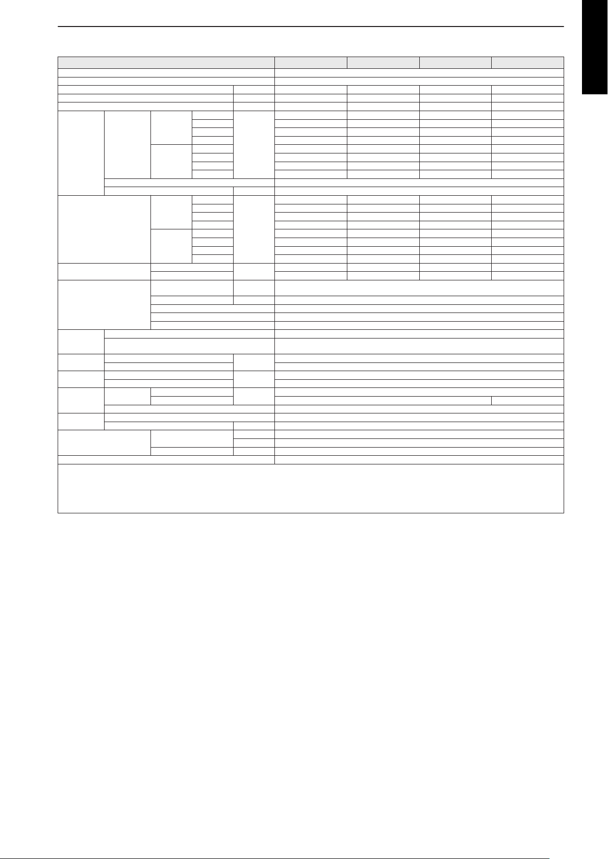
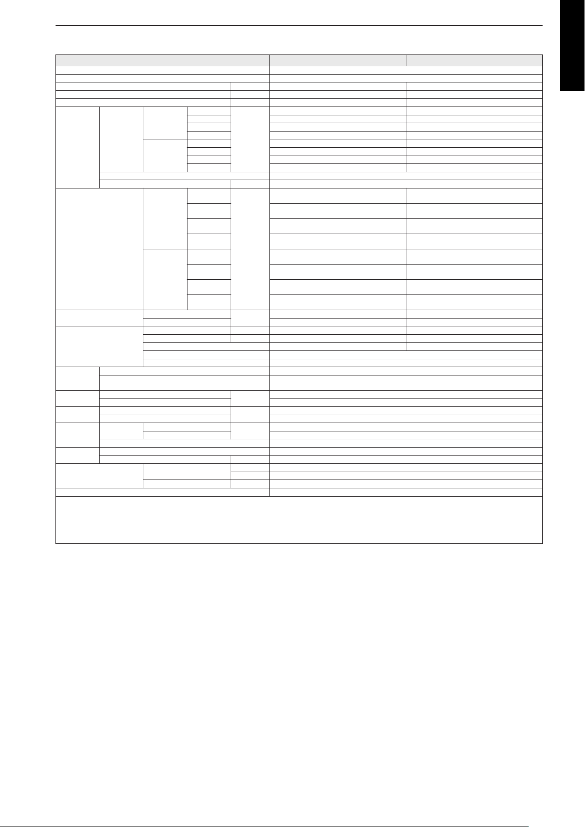
2-4. Wall mounted type
Model name ASYG07LUCA ASYG09LUCA ASYG12LUCA ASYG14LUCA
Power supply 1Ø 230 V ~50 Hz
Available voltage range 198—264 V
Capacity kW class 2.0 2.5 3.5 4.0
Input power W 13 16 19 23
Running current A 0.13 0.14 0.17 0.20
Cooling
Fan
Sound pressure level *
Sound power level
Heat exchanger type
Enclosure
Dimensions
(H × W × D)
Weight
Connection
pipe
Drain hose
Operation range
Remote controller type Wireless (Wired [option])
NOTES:
• The protective function might work when using it outside the operation range.
• *: Sound pressure level:
– These are the measured values in the manufacturer’s anechoic chamber.
– Because of the surrounding sound environment, the sound levels measured in actual installation conditions might be higher than the specified values here.
Airflow rate
Heating
Type × Q'ty Cross flow fan × 1
Motor output W 36
Cooling
Heating
Cooling
Heating 53 54 55 59
Dimensions (H × W × D) mm
Fin pitch mm Main: 1.1, Sub: 1.4
Rows × Stages Main: 2 × 20, Sub: 1 × 4
Pipe type Copper tube
Material Polystyrene
Color
Net
Gross 247 × 920 × 373
Net
Gross 12
Size
Method Flare
Material PP + LLDPE
Size mm Ø13.8 (I.D.), Ø15.8 to Ø16.7 (O.D.)
Fin type Aluminum
Liquid
Gas Ø9.52 (Ø3/8) Ø12.7 (Ø1/2)
Cooling
Heating °C 16 to 30
HIGH
MED 520 550 600 640
LOW 470 470 530 570
QUIET 330 330 330 390
HIGH 570 600 660 710
MED 520 550 600 640
LOW 470 470 530 590
QUIET 330 330 330 430
HIGH
MED 30 32 34 36
LOW 28 28 31 33
QUIET 21 21 21 25
HIGH 35 36 37 41
MED 30 32 34 36
LOW 28 28 31 34
QUIET 21 21 21 27
m3/h
dB (A)
dB (A)
mm
kg
mm (in)
°C 18 to 32
%RH 80 or less
570 600 660 710
35 36 37 41
53 54 55 59
Main: 320 × 690 × 20
Sub: 84 × 690 × 13.3
(Approximate color of Munsell N 9.3)
White
282 × 870 × 185
9.5
Ø6.35 (Ø1/4)
MULTI TYPE
5, 6 ROOMS TYPE
- 15 -
Page 24
Model name ASYG07LMCA ASYG09LMCA ASYG12LMCA ASYG14LMCA
Power supply 1Ø 230 V ~50 Hz
Available voltage range 198—264 V
Capacity kW class 2.0 2.5 3.5 4.0
Input power W 15 17 22 28
MULTI TYPE
Running current A 0.13 0.15 0.19 0.25
5, 6 ROOMS TYPE
Fan
Sound pressure level *
Sound power level
Heat exchanger type
Enclosure
Dimensions
(H × W × D)
Weight
Connection
pipe
Drain hose
Operation range
Remote controller type Wireless (Wired [option])
NOTES:
• The protective function might work when using it outside the operation range.
• *: Sound pressure level:
– These are the measured values in the manufacturer’s anechoic chamber.
– Because of the surrounding sound environment, the sound levels measured in actual installation conditions might be higher than the specified values here.
HIGH
Cooling
Airflow rate
Heating
Type × Q'ty Cross flow fan × 1
Motor output W 35
Cooling
Heating
Cooling
Heating 51 52 55 57
Dimensions (H × W × D) mm
Fin pitch mm Main: 1.1, Sub: 1.4
Rows × Stages Main: 2 × 20, Sub: 1 × 4
Pipe type Copper tube
Material Polystyrene
Color
Net
Gross 270 × 884 × 336
Net
Gross 10.5
Size
Method Flare
Material PP + LLDPE
Size mm Ø13.8 (I.D.), Ø15.8 to Ø16.7 (O.D.)
Fin type Aluminum
Liquid
Gas Ø9.52 (Ø3/8) Ø12.7 (Ø1/2)
Cooling
Heating °C 16 to 30
MED 500 520 560 600
LOW 430 430 450 530
QUIET 310 310 310 360
HIGH 560 600 660 730
MED 500 520 560 615
LOW 430 430 470 560
QUIET 330 330 330 375
HIGH
MED 32 33 36 38
LOW 29 29 30 33
QUIET 21 21 21 25
HIGH 36 37 40 42
MED 32 33 36 38
LOW 29 29 31 35
QUIET 22 22 22 27
m3/h
dB (A)
dB (A)
mm
kg
mm (in)
°C 18 to 32
%RH 80 or less
560 600 660 730
36 37 40 42
51 52 54 56
Main: 320 × 630 × 20
Sub: 84 × 630 × 13.3
(Approximate color of Munsell N 9.25/)
White
268 × 840 × 203
8.5
Ø6.35 (Ø1/4)
- 16 -
Page 25
Model name ASYG07LMCE ASYG09LMCE ASYG12LMCE ASYG14LMCE
Power supply 1Ø 230 V ~50 Hz
Available voltage range 198—264 V
Capacity kW class 2.0 2.5 3.5 4.0
Input power W 15 17 22 28
Running current A 0.13 0.15 0.19 0.25
Cooling
Fan
Sound pressure level *
Sound power level
Heat exchanger type
Enclosure
Dimensions
(H × W × D)
Weight
Connection
pipe
Drain hose
Operation range
Remote controller type Wireless (Wired [option])
NOTES:
• The protective function might work when using it outside the operation range.
• *: Sound pressure level:
– These are the measured values in the manufacturer’s anechoic chamber.
– Because of the surrounding sound environment, the sound levels measured in actual installation conditions might be higher than the specified values here.
Airflow rate
Heating
Type × Q'ty Cross flow fan × 1
Motor output W 35
Cooling
Heating
Cooling
Heating 51 52 55 57
Dimensions (H × W × D) mm
Fin pitch mm Main: 1.1, Sub: 1.4
Rows × Stages Main: 2 × 20, Sub: 1 × 4
Pipe type Copper tube
Material Polystyrene
Color
Net
Gross 270 × 925 × 336
Net
Gross 11.0
Size
Method Flare
Material PP + LLDPE
Size mm Ø13.8 (I.D.), Ø15.8 to Ø16.7 (O.D.)
Fin type Aluminum
Liquid
Gas Ø9.52 (Ø3/8) Ø12.7 (Ø1/2)
Cooling
Heating °C 16 to 30
HIGH
MED 500 520 560 600
LOW 430 430 450 530
QUIET 310 310 310 360
HIGH 560 600 660 730
MED 500 520 560 615
LOW 430 430 470 560
QUIET 330 330 330 375
HIGH
MED 32 33 36 38
LOW 29 29 30 33
QUIET 21 21 21 25
HIGH 36 37 40 42
MED 32 33 36 38
LOW 29 29 31 35
QUIET 22 22 22 27
m3/h
dB (A)
dB (A)
mm
kg
mm (in)
°C 18 to 32
%RH 80 or less
560 600 660 730
36 37 40 42
51 52 54 56
Main: 320 × 630 × 20
Sub: 84 × 630 × 13.3
(Approximate color of Munsell N 9.25/)
White
270 × 870 × 204
8.5
Ø6.35 (Ø1/4)
MULTI TYPE
5, 6 ROOMS TYPE
- 17 -
Page 26
MULTI TYPE
5, 6 ROOMS TYPE
Model name ASYG18LFCA ASYG24LFCA ASYG24LFCC
Power supply 1Ø 230 V ~50 Hz
Available voltage range 198—264 V
Capacity kW class 5.0 7.0
Input power W 37 69
Running current A 0.33 0.53
Cooling
Fan
Sound pressure level *
Sound power level
Heat exchanger type
Enclosure
Dimensions
(H × W × D)
Weight
Connection
pipe
Drain hose
Operation range
Remote controller type Wireless (Wired [option])
NOTES:
• The protective function might work when using it outside the operation range.
• *: Sound pressure level:
– These are the measured values in the manufacturer’s anechoic chamber.
– Because of the surrounding sound environment, the sound levels measured in actual installation conditions might be higher than the specified values here.
Airflow rate
Heating
Type × Q'ty Cross flow fan ×1
Motor output W 42 65
Cooling
Heating
Cooling
Heating 58 64
Dimensions (H × W × D) mm
Fin pitch mm Main: 1.2, Sub: 1.4
Rows × Stages Main: 2 × 18, Sub: 1 × 4 Main: 2 × 18, Sub: 1 × 4 + 1 × 4
Pipe type Copper tube
Material Polystyrene
Color
Net
Gross 329 × 1,090 × 420
Net
Gross 18
Size
Method Flare
Material PVC
Size mm Ø12 (I.D.), Ø16 (O.D.)
Fin type Aluminum
Liquid
Gas Ø12.70 (Ø1/2) Ø15.88 (Ø5/8)
Cooling
Heating °C 16 to 32
HIGH
MED 740 900
LOW 620 740
QUIET 550 620
HIGH 900 1,100
MED 740 900
LOW 620 740
QUIET 550 620
HIGH
MED 37 42
LOW 33 37
QUIET 26 33
HIGH 42 48
MED 37 42
LOW 33 37
QUIET 25 33
m3/h
dB (A)
dB (A)
mm
kg
mm (in)
°C 18 to 32
%RH 80 or less
900 1,120
43 49
58 64
Main: 378 × 832 × 26.6
Sub: 84 × 832 × 13.3
(Approximate color of Munsell N 9.25/)
White
320 × 998 × 238
14
Ø6.35 (Ø1/4)
- 18 -
Page 27
2-5. Floor/Ceiling type
Model name ABYG14LVTA ABYG18LVTB
Power supply 1Ø 230 V ~50 Hz
Available voltage range 198—264 V
Capacity kWh class 4.0 5.0
Input power W 26 47
Running current A 0.21 0.36
Cooling
Fan
Sound pressure level *
Sound power level
Heat exchanger type
Enclosure
Dimensions
(H × W × D)
Weight
Connection
pipe
Drain hose
Operation range
Remote controller type Wireless (Wired [option])
NOTES:
• The protective function might work when using it outside the operation range.
• *Sound pressure level:
– Measured values in manufacturer’s anechoic chamber.
– Because of the surrounding sound environment, the sound levels measured in actual installation conditions might be higher than the specified values here.
Airflow rate
Heating
Type × Q'ty Sirocco fan × 2
Motor output W 80
Cooling
Heating
Cooling
Heating 51 55
Dimensions (H × W × D) mm 252 × 800 × 26.6 252 × 800 × 39.9
Fin pitch mm 1.2 1.3
Rows × Stages 2 × 12 3 × 12
Pipe type Copper tube
Material ABS
Color
Net
Gross 320 × 1,150 × 790
Net
Gross 36
Size
Method Flare
Material Hard PVC
Size mm Ø25 (I.D.), Ø32 (O.D.)
Fin type Aluminum
Liquid
Gas Ø12.70 (Ø1/2)
Cooling
Heating °C 16 to 30
HIGH
MED 590 700
LOW 540 560
QUIET 480 500
HIGH 640 780
MED 590 700
LOW 540 560
QUIET 480 500
HIGH
MED
LOW
QUIET
HIGH
MED
LOW
QUIET
m3/h
dB (A)
dB (A)
mm
kg
mm (in)
°C 18 to 32
%RH 80 or less
640 780
36 (Under ceiling)
39 (Floor console)
34 (Under ceiling)
37 (Floor console)
33 (Under ceiling)
36 (Floor console)
29 (Under ceiling)
32 (Floor console)
36 (Under ceiling)
39 (Floor console)
34 (Under ceiling)
37 (Floor console)
33 (Under ceiling)
36 (Floor console)
29 (Under ceiling)
32 (Floor console)
51 55
(Approximate color of Munsell N 9.25/)
White
199 × 990 × 655
27
Ø6.35 (Ø1/4)
41 (Under ceiling)
44 (Floor console)
38 (Under ceiling)
41 (Floor console)
34 (Under ceiling)
37 (Floor console)
32 (Under ceiling)
35 (Floor console)
41 (Under ceiling)
44 (Floor console)
38 (Under ceiling)
41 (Floor console)
34 (Under ceiling)
37 (Floor console)
32 (Under ceiling)
35 (Floor console)
MULTI TYPE
5, 6 ROOMS TYPE
- 19 -
Page 28
2-6. Floor type
Model name AGYG09LVCA AGYG12LVCA AGYG14LVCA
Power supply 1Ø 230 V ~50 Hz
Available voltage range 198—264 V
MULTI TYPE
Capacity kW class 2.5 3.5 4.0
5, 6 ROOMS TYPE
Input power W 16 20 23
Running current A 0.15 0.18 0.20
Fan
Sound pressure level *
Sound power level
Heat exchanger type
Enclosure
Dimensions
(H × W × D)
Weight
Connection
pipe
Drain hose
Operation range
Remote controller type Wireless (Wired [option])
NOTES:
• The protective function might work when using it outside the operation range.
• *Sound pressure level:
– Measured values in manufacturer’s anechoic chamber.
– Because of the surrounding sound environment, the sound levels measured in actual installation conditions might be higher than the specified values here.
HIGH
Cooling
Airflow rate
Heating
Type × Q'ty Cross flow fan × 2
Motor output W 16
Cooling
Heating
Cooling
Heating 52 55 56
Dimensions (H × W × D) mm 378 × 550 × 26.6
Fin pitch mm 1.2
Rows × Stages 2 × 18
Pipe type Copper tube
Material Polystyrene
Color
Net
Gross 700 × 820 × 310
Net
Gross 17
Size
Method Flare
Material PVC
Size mm Ø13.8 (I.D.), Ø16.7 (O.D.)
Fin type Aluminum
Liquid
Gas Ø9.52 (Ø3/8) Ø12.70 (Ø1/2)
Cooling
Heating °C 16 to 30
MED 440 490 520
LOW 360 380 400
QUIET 270 270 270
HIGH 530 600 650
MED 460 510 540
LOW 380 410 430
QUIET 270 270 270
HIGH
MED 34 36 38
LOW 28 30 31
QUIET 22 22 22
HIGH 39 42 44
MED 35 38 39
LOW 30 32 33
QUIET 22 22 22
m3/h
dB (A)
dB (A)
mm
kg
mm (in)
°C 18 to 32
%RH 80 or less
530 600 650
39 42 44
52 55 56
(Approximate color of Munsell N 9.25/)
White
600 × 740 × 200
14
Ø6.35 (Ø1/4)
- 20 -
Page 29
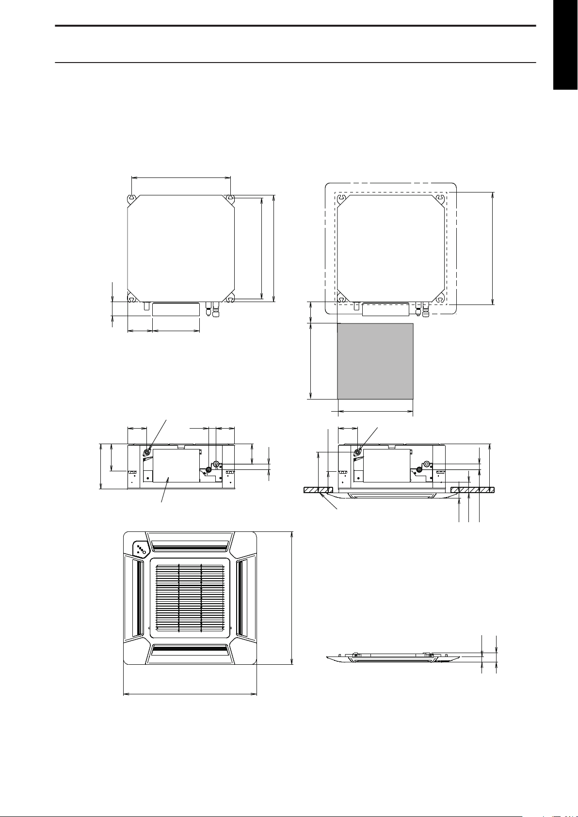
3. Dimensions
530: Hanging bolt position
102
135
250
700
700
75
30
30
262
540: Hanging bolt position
570: Indoor unit
580 to 660
: Ceiling openings
•
Cassette grille mounting state
Top view
150 to 200
Min. 450
Min. 450
Service access
Side view
215
123
58
114
146
108
102
245
30
40
99
Drain port
Control box
Ceiling
Drain port
Be sure to leave
service access
for future service
at the designated
position.
Bottom view
30
49
Side view
Unit: mm
3-1. Compact cassette type
¢ Models: AUYG07LVLA, AUYG09LVLA, AUYG12LVLB,
AUYG14LVLB, and AUYG18LVLB
MULTI TYPE
5, 6 ROOMS TYPE
- 21 -
Page 30
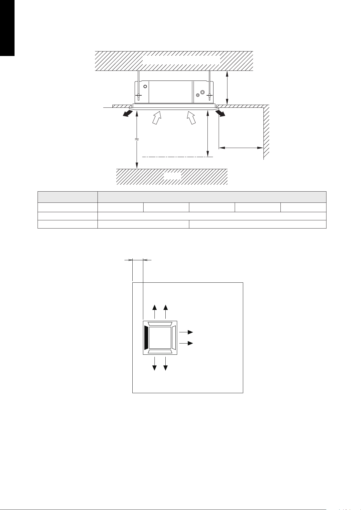
¢
1,000
or more
1,000
or more
1,800
or more
262
or more
Strong and durable ceiling
Obstruction
Floor
Unit: mm
100 or more*
Unit: mm
MULTI TYPE
5, 6 ROOMS TYPE
Installation space
Maximum height from floor to ceiling (Unit: mm)
Model name AUYG07LVLA AUYG09LVLA
Standard mode 2,700
High ceiling mode — 3,000
AUYG12LVLB AUYG14LVLB AUYG18LVLB
• 3-way direction setting
NOTES:
• *: When installing the indoor unit, be careful about the maintenance space.
• To set “3-direction”, optional Air outlet shutter plate (UTR-YDZB) must be installed, and the
“outlet-direction” need to be switched to “3-way” by remote controller.
• The ceiling height cannot be set in the 3-way outlet mode. Therefore, ceiling height setting
change by function setting 20 is prohibited. For details, refer to "Contents of function setting"
on page 241.
- 22 -
Page 31

3-2. Mini duct type
Drain port
575
174
752
650
43
33
665
700
650
49
49
92
78
169
56
66
85
P 100 × 6 = 600
A
295
198
168
150
78 57
10
30
150
182
193
450
30
153
72
52
Rear view
Top view
Front view Bottom view
Side view
View A
Unit: mm
¢ Models: ARYG07LSLAP, ARYG09LSLAP, ARYG12LSLAP,
and ARYG14LSLAP
MULTI TYPE
5, 6 ROOMS TYPE
- 23 -
Page 32

¢ Model: ARYG18LSLAP
Drain port
A
Unit: mm
Rear view
View A
Top view
Side view
Front view
Bottom view
775
174
153
72
52
295
30
49
85
952
850
P 100 × 8 = 800
49
92
78
169
56
66
10
30
150
182
193
450
850
43
33
864
900
198
168
150
78 57
MULTI TYPE
5, 6 ROOMS TYPE
- 24 -
Page 33

Installation space requirement
150
or more*
400
or more
Unit: mm
Strong and durable ceiling
Indoor unit
*: 400 or more when drain from drain pipe
Right
side
Left
side
Service access Ceiling
2,500 or more
(When no ceiling)
Floor
225 or more
5 or more
20 or more
300 or more
Air
100 or more
Air
Unit: mm
Top view
Service access
Air
Air
Control box
400 or more
100 or more
300 or more*
Service space
*: More than 100 when intaking air from bottom
¢
Provide sufficient installation space for product safety.
MULTI TYPE
5, 6 ROOMS TYPE
• When intaking air from back:
Maintenance space requirement
¢
• When intaking air from bottom:
For future maintenance and service access, provide sufficient maintenance space.
NOTE: Do not place any wiring or illumination in the maintenance space, as they will impede
service.
- 25 -
Page 34

3-3. Slim duct type
Rear view
View A
Top view
Side view
Front view
Bottom view
Drain port
51
574
174
71
152
100 x 6 = 600
82
48
650
734
30
377
167
119
89
78
55
47
10
620
371
264
144
69
650
664
700
43
20
198
168
151
78 55
Unit: mm
¢ Models: ARYG07LLTA, ARYG09LLTA, ARYG12LLTB, and
MULTI TYPE
5, 6 ROOMS TYPE
ARYG14LLTB
- 26 -
Page 35

¢ Model: ARYG18LLTB
Rear view
View A
Top view
Side view
Front view
Bottom view
Drain port
51
774
174
71
152
87
56
850
934
100 x 8 = 800
30
377
167
119
89
78
55
47
10
620
371
264
144
69
850
864
900
43
20
198
168
151
78
55
Unit: mm
MULTI TYPE
5, 6 ROOMS TYPE
- 27 -
Page 36

¢
Left
side
Strong and durable ceiling
Indoor unit
Right
side
100
or more
300
or more
Service access Ceiling
2500 or more
(When no ceiling)
Floor
240 or more
20 or more
20 or more
300 or more
Unit: mm
10
or less
10
or less
Left side
Strong and
durable floor
Right side
(PIPE side)
Grille
Inlet air
Strong and
durable floor
150
or more
150
or more
300
or more
100
or more
20
or more
20
or more
Unit: mm
Left side
Strong and
durable floor
Right side
(PIPE side)
Duct
Grille
Inlet air
Strong and
durable floor
150
or more
150
or more
100
or more
300
or more
20
or more
20
or more
MULTI TYPE
5, 6 ROOMS TYPE
Installation space requirement
Provide sufficient installation space for product safety.
In ceiling-concealed installations:
In wall-concealed installations:
- 28 -
Page 37

Maintenance space requirement
Service access
Unit: mm
Unit
Control box
Service space
300
or more
300
or more
100
or more
¢
For future maintenance and service access, provide sufficient maintenance space.
NOTE: Do not place any wiring or illumination in the maintenance space, as they will impede
service.
MULTI TYPE
5, 6 ROOMS TYPE
- 29 -
Page 38

3-4. Wall mounted type
Unit: mm
268
(268)
34216
209
74
840 203
(840)
410
310
430
165 144
178 233
321 315
295
Outline of unit
65 for pipe inlet
65 for pipe inlet
¢
MULTI TYPE
5, 6 ROOMS TYPE
Models: ASYG07LMCA, ASYG09LMCA, ASYG12LMCA, and ASYG14LMCA
- 30 -
Page 39

Installation space
Unit: mm
45 or more
1,800 or more
63 or more
Outline of unit
25 or more
52 or more
130 or more
1,500 or more
70 or more
MULTI TYPE
5, 6 ROOMS TYPE
- 31 -
Page 40

¢ Models: ASYG07LMCE, ASYG09LMCE, ASYG12LMCE, and
Unit: mm
270
(270)
34218
209
74
870 204
(870)
426
310
444
165 144
178 233
321 315
295
Outline of unit
65 for pipe inlet
65 for pipe inlet
MULTI TYPE
5, 6 ROOMS TYPE
ASYG14LMCE
- 32 -
Page 41

Installation space requirement
Unit: mm
45 or more
1,800 or more
63 or more
Outline of unit
25 or more
52 or more
144 or more
1,500 or more
86 or more
Provide sufficient installation space for product safety.
MULTI TYPE
5, 6 ROOMS TYPE
- 33 -
Page 42

¢ Models: ASYG07LUCA, ASYG09LUCA, ASYG12LUCA, and
Unit: mm
282
870 185
187: Installed state
Outline of Unit
Ø65
for pipe inlet
Ø65
for pipe inlet
MULTI TYPE
5, 6 ROOMS TYPE
ASYG14LUCA
- 34 -
Page 43

Installation space
Unit: mm
50 or more
Outline of unit
160 or more
1,500 or more
1,800 or more
337
247
55
50 or more
160 or more
100 or more
120 or more
MULTI TYPE
5, 6 ROOMS TYPE
- 35 -
Page 44

¢
998
238
320
998
Outline of unit
471
67
28
46
43861 102397
432
56
56
10
320
ø80
ø80
17
Unit: mm
MULTI TYPE
5, 6 ROOMS TYPE
Models: ASYG18LFCA, ASYG24LFCA, and ASYG24LFCC
- 36 -
Page 45

Installation space
63 or more
80 or more
53 or more
52 or more
80 or more
Outline of unit
120 or more
1,500 or more
1,800 or more
Unit: mm
Provide sufficient installation space for product safety.
MULTI TYPE
5, 6 ROOMS TYPE
- 37 -
Page 46

3-5. Floor/Ceiling type
Side view Rear view
Bottom view
100 hole
50 hole
125
100
655
530
45
65
500 245
990
65
Wall bracket
Side of unit
Unit: mm
500
900
990
100 28
47 100
124
100
100
175 200
530
655
43
13
100
124 742
56
72
67
63
27
98
199
162
100
190
145
20
ø45-mm hole
(Use M10 screw
bolt.)
Hole for lifting bolt
¢ Models: ABYG14LVTA and ABYG18LVTB
MULTI TYPE
5, 6 ROOMS TYPE
- 38 -
Page 47

Installation space
Left Right
300 or more 300 or more
Ceiling
Left
Indoor unit
Right
150 or more 300 or more
Ceiling
20 or more
1,000 or more
2,300 or more
Obstruction
Floor
Unit: mm
¢
MULTI TYPE
5, 6 ROOMS TYPE
- 39 -
Page 48

3-6. Floor type
600
200
Side view
Front view
740
Unit: mm
80 or more
50 or more
80 or more
100 or more
100 or below from the floor
Unit: mm
¢ Models: AGYG09LVCA, AGYG12LVCA, and AGYG14LVCA
MULTI TYPE
5, 6 ROOMS TYPE
Installation space
¢
- 40 -
Page 49

4. Wiring diagrams
4-1. Compact cassette type
¢ Models: AUYG07LVLA, AUYG09LVLA, AUYG12LVLB,
AUYG14LVLB, and AUYG18LVLB
MULTI TYPE
5, 6 ROOMS TYPE
- 41 -
Page 50

4-2. Mini duct type
WLAN adapter,
Converter etc.
(Option)
¢ Models: ARYG07LSLAP, ARYG09LSLAP, ARYG12LSLAP,
MULTI TYPE
5, 6 ROOMS TYPE
ARYG14LSLAP, and ARYG18LSLAP
- 42 -
Page 51

4-3. Slim duct type
THERMISTOR
(PIPE TEMP.)
THERMISTOR
(ROOM TEMP.)
BLACK
BLACK
BLACK
BLACK
BLACK
BLACK
BLACK
GRAY
RECEIVER UNIT
(OPTION)
FRESH AIR
(OPTION)
CN5
CN8CN7
12
12
12
12
TERMINAL
123
E101 E102 E103
GREEN
GREEN
GREEN
YELLOW
YELLOW
WHITE
WHITE
CN102 CN106 CN108
123
12
W105
W102
W101
1
2
1
2
FM
CN105
1
2
3
4
5
6
1
2
3
4
5
6
CN104
CN101
12345678
123
123
123
123
123
12
12
45678
GRAY
GRAY
GRAY
GRAY
GRAY
GRAY
GRAY
GRAY
GRAY
GRAY
GRAY
CN4
CN1
12345678
123
123
123
45678
CN10
CN103
CN3
CN13
CN14
CN6
BROWN
RED
RED
RED
YELLOW
WHITE
WHITE
WHITE
CN11
1
2
3
CN9
1
2
3
CN12
1
2
3
4
5
1
2
3
4
5
1
2
3
1
2
1
2
3
1
2
3
4
5
6
1
2
3
4
5
6
7
TERMINAL
123
M
PRINTED
CIRCUIT
BOARD
(MAIN)
LOUVER
(OPTION)
HEATER
(OPTION)
PRINTED
CIRCUIT
BOARD
(POWER)
DRAIN PUMP
MOTOR
GRAY
FLOAT SWITCH
FAN MOTOR
REACTOR
TO REMOTE
CONTROL UNIT
¢ Models: ARYG07LLTA, ARYG09LLTA, ARYG12LLTB,
ARYG14LLTB, and ARYG18LLTB
MULTI TYPE
5, 6 ROOMS TYPE
- 43 -
Page 52

4-4. Wall mounted type
¢
MULTI TYPE
5, 6 ROOMS TYPE
Models: ASYG07LUCA, ASYG09LUCA, ASYG12LUCA, and ASYG14LUCA
- 44 -
Page 53

Models: ASYG07LMCA, ASYG09LMCA, ASYG12LMCA,
¢
ASYG14LMCA, ASYG07LMCE, ASYG09LMCE, ASYG12LMCE
and ASYG14LMCE
MULTI TYPE
5, 6 ROOMS TYPE
- 45 -
Page 54

¢
MULTI TYPE
5, 6 ROOMS TYPE
Models: ASYG18LFCA, ASYG24LFCA, and ASYG24LFCC
- 46 -
Page 55

4-5. Floor/Ceiling type
¢ Models: ABYG14LVTA and ABYG18LVTB
MULTI TYPE
5, 6 ROOMS TYPE
- 47 -
Page 56

4-6. Floor type
¢ Models: AGYG09LVCA, AGYG12LVCA, and AGYG14LVCA
MULTI TYPE
5, 6 ROOMS TYPE
- 48 -
Page 57

5. Air velocity and temperature distributions
2.0
2.0
2.0
2.0
1.0
1.0
1.0
1.0
0.5
0.5
0.5
0.5
0.25
0.25
0.25
0.25
Unit : m/s
4
3
2
1
0
1
2
3
4
43
210
1
2
34
(m)
(m)
2.0
1.0
0.5 0.5
0.25 0.25
43
2
1
0
1
2
34
(m)
0
1
2
2.7
(m)
Unit : m/s
5-1. Compact cassette type
Models: AUYG07LVLA and AUYG09LVLA
¢
• Air velocity distribution
Measuring conditions
Top view
Vertical airflow direction louver: up
Fan speed Operation mode
HIGH FAN
MULTI TYPE
5, 6 ROOMS TYPE
Side view
Vertical airflow direction louver: up
- 49 -
Page 58

2.0 2.0
1.5 1.5
1.0 1.0
0.5 0.5
0.25 0.25
4
3
2
1
0
1
2
34
(m)
0
1
2
2.7
(m)
2.5
Unit : m/s
30 30
28 28
26 26
24 24
22 22
4
3
2
1
0
1
2
34
(m)
0
1
2
2.7
(m)
2.5
Unit : °C
MULTI TYPE
5, 6 ROOMS TYPE
• Air velocity distribution
Measuring conditions
NOTE: Reference data
Side view
Vertical airflow direction louver: down
• Air temperature distribution
Measuring conditions
NOTE: Reference data
Side view
Vertical airflow direction louver: down
Fan speed Operation mode Outlet directions
HIGH HEAT 4-way air outlet
Fan speed Operation mode Outlet directions
HIGH HEAT 4-way air outlet
- 50 -
Page 59

Model: AUYG12LVLB
2.0
2.0
2.0
2.0
1.0
1.0
1.0
1.0
0.5
0.5
0.5
0.5
0.25
0.25
0.25
0.25
43
2
1
0
1
2
34
(m)
Unit : m/s
4
3
2
1
0
1
2
3
4
(m)
2.0
1.0
0.5
0.5
0.25
0.25
43
210
1
2
34
(m)
0
1
2
2.7
(m)
Unit : m/s
¢
• Air velocity distribution
Measuring conditions
Top view
Vertical airflow direction louver: up
Fan speed Operation mode
HIGH FAN
MULTI TYPE
5, 6 ROOMS TYPE
Side view
Vertical airflow direction louver: up
- 51 -
Page 60

1.5 1.5
1.0 1.0
0.5 0.5
0.25 0.25
0
1
2
2.7
(m)
2.5
4
3
210
1
2
34
(m)
Unit : m/s
30 30
28 28
26 26
24 24
22 22
0
1
2
2.7
(m)
2.5
43
2
1
0
1
2
34
(m)
Unit : °C
MULTI TYPE
5, 6 ROOMS TYPE
• Air velocity distribution
Measuring conditions
NOTE:Reference data
Side view
Vertical airflow direction louver: down
• Air temperature distribution
Measuring conditions
NOTE:Reference data
Side view
Vertical airflow direction louver: down
Fan speed Operation mode Outlet directions
HIGH HEAT 4-way air outlet
Fan speed Operation mode Outlet directions
HIGH HEAT 4-way air outlet
- 52 -
Page 61

Model: AUYG14LVLB
1
0.5
0.5
1
2
0.25
0.25
1
0.25
2
0.25
0.5
2
0.5
1
2
43
2
1
0
1
2
34
(m)
Unit : m/s
4
3
2
1
0
1
2
3
4
(m)
0.25
0.25
0.5
0.5
1
1
2
2
43
210
1
2
34
(m)
0
1
2
2.7
(m)
Unit : m/s
¢
• Air velocity distribution
Measuring conditions
Top view
Vertical airflow direction louver: up
Fan speed Operation mode
HIGH FAN
MULTI TYPE
5, 6 ROOMS TYPE
Side view
Vertical airflow direction louver: up
- 53 -
Page 62

0.25
0.5
1.0
1.5
2.0
0
1
2
2.7
(m)
2.5
4
3
210
1
2
34
(m)
Unit : m/s
22
24
26
28
30
0
1
2
2.7
(m)
2.5
43
2
1
0
1
2
34
(m)
Unit : °C
MULTI TYPE
5, 6 ROOMS TYPE
• Air velocity distribution
Measuring conditions
NOTE:Reference data
Side view
Vertical airflow direction louver: down
• Air temperature distribution
Measuring conditions
NOTE:Reference data
Side view
Vertical airflow direction louver: down
Fan speed Operation mode Outlet directions
HIGH HEAT 4-way air outlet
Fan speed Operation mode Outlet directions
HIGH HEAT 4-way air outlet
- 54 -
Page 63

Model: AUYG18LVLB
43
2
1
0
1
2
34
(m)
Unit : m/s
4
3
2
1
0
1
2
3
4
(m)
2.0
2.0
2.0
2.0
1.0
1.0
1.0
1.0
0.5
0.5
0.5
0.5
0.25
0.25
0.25
0.25
43
210
1
2
34
(m)
0
1
2
2.7
(m)
Unit : m/s
2.0
1.0
0.5
0.5
0.25
0.25
¢
• Air velocity distribution
Measuring conditions
Top view
Vertical airflow direction louver: up
Fan speed Operation mode
HIGH FAN
MULTI TYPE
5, 6 ROOMS TYPE
Side view
Vertical airflow direction louver: up
- 55 -
Page 64

0
1
2
2.7
(m)
2.5
4
3
210
1
2
34
(m)
Unit : m/s
1.5 1.5
1.0 1.0
0.5 0.5
0.25 0.25
2.0 2.0
0
1
2
2.7
(m)
2.5
43
2
1
0
1
2
34
Unit : °C
30 30
28 28
26 26
24 24
22 22
MULTI TYPE
5, 6 ROOMS TYPE
• Air velocity distribution
Measuring conditions
NOTE:Reference data
Side view
Vertical airflow direction louver: down
• Air temperature distribution
Measuring conditions
NOTE:Reference data
Side view
Vertical airflow direction louver: down
Fan speed Operation mode Outlet directions
HIGH HEAT 4-way air outlet
Fan speed Operation mode Outlet directions
HIGH HEAT 4-way air outlet
- 56 -
Page 65

5-2. Mini duct type
2
1
0
1
2
(m)
Unit: m/s
(m)
0
123
456
789
10
2
1
0.5
2
1
0
1
2
(m)
(m)
Unit: m/s
0
123
456
7
5
4
3
89
10
5
4
3
2
1
0.5
2
1
0.5
2
1
0
(m)
Unit: m/s
(m)
012 3
4
5678910
2.5
3
1
0.5
2
Model: ARYG07LSLAP
¢
NOTE: This data is measured after installing optional Auto louver grille kit.
• Air velocity distribution
Measuring conditions
Top view
Vertical airflow direction louver: Up
Horizontal airflow direction louver: Center
Fan speed Operation mode
HIGH FAN
MULTI TYPE
5, 6 ROOMS TYPE
Top view
Vertical airflow direction louver: Up
Horizontal airflow direction louver: Left & Right
Side view
Vertical airflow direction louver: Up
Horizontal airflow direction louver: Center
- 57 -
Page 66

2
1
0
(m)
Unit: m/s
(m)
0
12 345678910
2.5
3
2
1
0.5
2
1
0
(m)
Unit: °C
(m)
01 2 34 5 6 78 9
2.5
3
10
30
28
26
24
22
MULTI TYPE
5, 6 ROOMS TYPE
• Air velocity distribution
Measuring conditions
Side view
Vertical airflow direction louver: Down
Horizontal airflow direction louver: Center
• Air temperature distribution
Measuring conditions
Side view
Vertical airflow direction louver: Down
Horizontal airflow direction louver: Center
Fan speed Operation mode
HIGH HEAT
Fan speed Operation mode
HIGH HEAT
- 58 -
Page 67

Model: ARYG09LSLAP
2
1
0
1
2
(m)
Unit: m/s
(m)
0
12 3
456
78 9
10
2
1
0.5
2
1
0
1
2
(m)
(m)
Unit: m/s
0
12 3
456
7
5
4
3
89
10
5
4
3
2
1
0.5
2
1
0.5
2
1
0
(m)
Unit: m/s
(m)
0
12 3
456
78 9
10
2.5
3
1
0.5
2
¢
NOTE: This data is measured after installing optional Auto louver grille kit.
• Air velocity distribution
Measuring conditions
Top view
Vertical airflow direction louver: Up
Horizontal airflow direction louver: Center
Fan speed Operation mode
HIGH FAN
MULTI TYPE
5, 6 ROOMS TYPE
Top view
Vertical airflow direction louver: Up
Horizontal airflow direction louver: Left & Right
Side view
Vertical airflow direction louver: Up
Horizontal airflow direction louver: Center
- 59 -
Page 68

2
1
0
(m)
Unit: m/s
(m)
0
12 3
456
78 9
10
2.5
3
2
1
0.5
2
1
0
(m)
Unit: °C
(m)
0
12 3
456
78 9
2.5
3
10
30
28
26
24
22
MULTI TYPE
5, 6 ROOMS TYPE
• Air velocity distribution
Measuring conditions
Side view
Vertical airflow direction louver: Down
Horizontal airflow direction louver: Center
• Air temperature distribution
Measuring conditions
Side view
Vertical airflow direction louver: Down
Horizontal airflow direction louver: Center
Fan speed Operation mode
HIGH HEAT
Fan speed Operation mode
HIGH HEAT
- 60 -
Page 69

Model: ARYG12LSLAP
2
1
0
1
2
(m)
Unit: m/s
(m)
0
12 3
456
78 9
10
2
1
0.5
2
1
0
1
2
(m)
(m)
Unit: m/s
0
12 3
456
7
5
4
3
89
10
5
4
3
2
1
0.5
2
1
0.5
2
1
0
(m)
Unit: m/s
(m)
0
12 3
456
78 9
10
2.5
3
1
0.5
2
¢
NOTE: This data is measured after installing optional Auto louver grille kit.
• Air velocity distribution
Measuring conditions
Top view
Vertical airflow direction louver: Up
Horizontal airflow direction louver: Center
Fan speed Operation mode
HIGH FAN
MULTI TYPE
5, 6 ROOMS TYPE
Top view
Vertical airflow direction louver: Up
Horizontal airflow direction louver: Left & Right
Side view
Vertical airflow direction louver: Up
Horizontal airflow direction louver: Center
- 61 -
Page 70

2
1
0
(m)
(m)
0
12 3
456
78 9
10
2.5
3
2
1
0.5
Unit: m/s
2
1
0
(m)
Unit: °C
(m)
0
12 3
456
78 9
2.5
3
10
30
28
26
24
22
MULTI TYPE
5, 6 ROOMS TYPE
• Air velocity distribution
Measuring conditions
Side view
Vertical airflow direction louver: Down
Horizontal airflow direction louver: Center
• Air temperature distribution
Measuring conditions
Side view
Vertical airflow direction louver: Down
Horizontal airflow direction louver: Center
Fan speed Operation mode
HIGH HEAT
Fan speed Operation mode
HIGH HEAT
- 62 -
Page 71

Model: ARYG14LSLAP
2
1
0
1
2
(m)
Unit: m/s
(m)
0
123
456
789
10
2
1
0.5
2
1
0
1
2
(m)
(m)
Unit: m/s
0123 4 56 7
5
4
3
8910
5
4
3
2
1
0.5
2
1
0.5
2
1
0
(m)
Unit: m/s
(m)
012 34 56 78 910
2.5
3
1
0.5
2
¢
NOTE: This data is measured after installing optional Auto louver grille kit.
• Air velocity distribution
Measuring conditions
Top view
Vertical airflow direction louver: Up
Horizontal airflow direction louver: Center
Fan speed Operation mode
HIGH FAN
MULTI TYPE
5, 6 ROOMS TYPE
Top view
Vertical airflow direction louver: Up
Horizontal airflow direction louver: Left & Right
Side view
Vertical airflow direction louver: Up
Horizontal airflow direction louver: Center
- 63 -
Page 72

2
1
0
(m)
Unit: m/s
(m)
012 3
45678910
2.5
3
2
1
0.5
2
1
0
(m)
Unit: °C
(m)
012345678 9
2.5
3
10
30
28
26
24
22
MULTI TYPE
5, 6 ROOMS TYPE
• Air velocity distribution
Measuring conditions
Side view
Vertical airflow direction louver: Down
Horizontal airflow direction louver: Center
• Air temperature distribution
Measuring conditions
Side view
Vertical airflow direction louver: Down
Horizontal airflow direction louver: Center
Fan speed Operation mode
HIGH HEAT
Fan speed Operation mode
HIGH HEAT
- 64 -
Page 73

Model: ARYG18LSLAP
2
1
0
1
2
(m)
Unit: m/s
(m)
0
12 3
456
78 9
10
2
1
0.5
2
1
0
1
2
(m)
(m)
Unit: m/s
0
12 3
456
7
5
4
3
89
10
5
4
3
2
1
0.5
2
1
0.5
2
1
0
(m)
Unit: m/s
(m)
0
12 3
456
78 9
10
2.5
3
1
0.5
2
¢
NOTE: This data is measured after installing optional Auto louver grille kit.
• Air velocity distribution
Measuring conditions
Top view
Vertical airflow direction louver: Up
Horizontal airflow direction louver: Center
Fan speed Operation mode
HIGH FAN
MULTI TYPE
5, 6 ROOMS TYPE
Top view
Vertical airflow direction louver: Up
Horizontal airflow direction louver: Left & Right
Side view
Vertical airflow direction louver: Up
Horizontal airflow direction louver: Center
- 65 -
Page 74

2
1
0
(m)
(m)
0
12 3
456
78 9
10
2.5
3
Unit: m/s
2
1
0.5
2
1
0
(m)
Unit: °C
(m)
0
12 3
456
78 9
2.5
3
10
30
28
26
24
22
MULTI TYPE
5, 6 ROOMS TYPE
• Air velocity distribution
Measuring conditions
Side view
Vertical airflow direction louver: Down
Horizontal airflow direction louver: Center
• Air temperature distribution
Measuring conditions
Side view
Vertical airflow direction louver: Down
Horizontal airflow direction louver: Center
Fan speed Operation mode
HIGH HEAT
Fan speed Operation mode
HIGH HEAT
- 66 -
Page 75

5-3. Slim duct type
2
1
0
1
2
(m)
Unit: m/s
(m)
0
123
456
789
10
2
1
0.5
2
1
0
1
2
(m)
(m)
Unit: m/s
0
123
456
7
5
4
3
89
10
5
4
3
2
1
0.5
2
1
0.5
2
1
0
(m)
Unit: m/s
(m)
012 3
4
5678910
2.5
3
1
0.5
2
Model: ARYG07LLTA
¢
NOTE: This data is measured after installing optional Auto louver grille kit.
• Air velocity distribution
Measuring conditions
Top view
Vertical airflow direction louver: Up
Horizontal airflow direction louver: Center
Fan speed Operation mode
HIGH FAN
MULTI TYPE
5, 6 ROOMS TYPE
Top view
Vertical airflow direction louver: Up
Horizontal airflow direction louver: Left & Right
Side view
Vertical airflow direction louver: Up
Horizontal airflow direction louver: Center
- 67 -
Page 76

2
1
0
(m)
Unit: m/s
(m)
0
12 34 5678 910
2.5
3
2
1
0.5
2
1
0
(m)
Unit: °C
(m)
01 2 34 5 6 78 9
2.5
3
10
30
28
26
24
22
MULTI TYPE
5, 6 ROOMS TYPE
• Air velocity distribution
Measuring conditions
Side view
Vertical airflow direction louver: Down
Horizontal airflow direction louver: Center
• Air temperature distribution
Measuring conditions
Side view
Vertical airflow direction louver: Down
Horizontal airflow direction louver: Center
Fan speed Operation mode
HIGH HEAT
Fan speed Operation mode
HIGH HEAT
- 68 -
Page 77

Model: ARYG09LLTA
2
1
0
1
2
(m)
Unit: m/s
(m)
0
12 3
456
78 9
10
2
1
0.5
2
1
0
1
2
(m)
(m)
Unit: m/s
0
12 3
456
7
5
4
3
89
10
5
4
3
2
1
0.5
2
1
0.5
2
1
0
(m)
Unit: m/s
(m)
0
12 3
456
78 9
10
2.5
3
1
0.5
2
¢
NOTE: This data is measured after installing optional Auto louver grille kit.
• Air velocity distribution
Measuring conditions
Top view
Vertical airflow direction louver: Up
Horizontal airflow direction louver: Center
Fan speed Operation mode
HIGH FAN
MULTI TYPE
5, 6 ROOMS TYPE
Top view
Vertical airflow direction louver: Up
Horizontal airflow direction louver: Left & Right
Side view
Vertical airflow direction louver: Up
Horizontal airflow direction louver: Center
- 69 -
Page 78

2
1
0
(m)
Unit: m/s
(m)
0
12 3
456
78 9
10
2.5
3
2
1
0.5
2
1
0
(m)
Unit: °C
(m)
0
12 3
456
78 9
2.5
3
10
30
28
26
24
22
MULTI TYPE
5, 6 ROOMS TYPE
• Air velocity distribution
Measuring conditions
Side view
Vertical airflow direction louver: Down
Horizontal airflow direction louver: Center
• Air temperature distribution
Measuring conditions
Side view
Vertical airflow direction louver: Down
Horizontal airflow direction louver: Center
Fan speed Operation mode
HIGH HEAT
Fan speed Operation mode
HIGH HEAT
- 70 -
Page 79

Model: ARYG12LLTB
2
1
0
1
2
(m)
Unit: m/s
(m)
0
12 3
456
78 9
10
2
1
0.5
2
1
0
1
2
(m)
(m)
Unit: m/s
0
12 3
456
7
5
4
3
89
10
5
4
3
2
1
0.5
2
1
0.5
2
1
0
(m)
Unit: m/s
(m)
0
12 3
456
78 9
10
2.5
3
1
0.5
2
¢
NOTE: This data is measured after installing optional Auto louver grille kit.
• Air velocity distribution
Measuring conditions
Top view
Vertical airflow direction louver: Up
Horizontal airflow direction louver: Center
Fan speed Operation mode
HIGH FAN
MULTI TYPE
5, 6 ROOMS TYPE
Top view
Vertical airflow direction louver: Up
Horizontal airflow direction louver: Left & Right
Side view
Vertical airflow direction louver: Up
Horizontal airflow direction louver: Center
- 71 -
Page 80

2
1
0
(m)
(m)
0
12 3
456
78 9
10
2.5
3
2
1
0.5
Unit: m/s
2
1
0
(m)
Unit: °C
(m)
0
12 3
456
78 9
2.5
3
10
30
28
26
24
22
MULTI TYPE
5, 6 ROOMS TYPE
• Air velocity distribution
Measuring conditions
Side view
Vertical airflow direction louver: Down
Horizontal airflow direction louver: Center
• Air temperature distribution
Measuring conditions
Side view
Vertical airflow direction louver: Down
Horizontal airflow direction louver: Center
Fan speed Operation mode
HIGH HEAT
Fan speed Operation mode
HIGH HEAT
- 72 -
Page 81

Model: ARYG14LLTB
2
1
0
1
2
(m)
Unit: m/s
(m)
0
123
456
789
10
2
1
0.5
2
1
0
1
2
(m)
(m)
Unit: m/s
0123 4 56 7
5
4
3
8910
5
4
3
2
1
0.5
2
1
0.5
2
1
0
(m)
Unit: m/s
(m)
012 34 56 78 910
2.5
3
1
0.5
2
¢
NOTE: This data is measured after installing optional Auto louver grille kit.
• Air velocity distribution
Measuring conditions
Top view
Vertical airflow direction louver: Up
Horizontal airflow direction louver: Center
Fan speed Operation mode
HIGH FAN
MULTI TYPE
5, 6 ROOMS TYPE
Top view
Vertical airflow direction louver: Up
Horizontal airflow direction louver: Left & Right
Side view
Vertical airflow direction louver: Up
Horizontal airflow direction louver: Center
- 73 -
Page 82

2
1
0
(m)
Unit: m/s
(m)
012 3
45678910
2.5
3
2
1
0.5
2
1
0
(m)
Unit: °C
(m)
0123456789
2.5
3
10
30
28
26
24
22
MULTI TYPE
5, 6 ROOMS TYPE
• Air velocity distribution
Measuring conditions
Side view
Vertical airflow direction louver: Down
Horizontal airflow direction louver: Center
• Air temperature distribution
Measuring conditions
Side view
Vertical airflow direction louver: Down
Horizontal airflow direction louver: Center
Fan speed Operation mode
HIGH HEAT
Fan speed Operation mode
HIGH HEAT
- 74 -
Page 83

Model: ARYG18LLTB
2
1
0
1
2
(m)
Unit: m/s
(m)
0
12 3
456
78 9
10
2
1
0.5
2
1
0
1
2
(m)
(m)
Unit: m/s
0
12 3
456
7
5
4
3
89
10
5
4
3
2
1
0.5
2
1
0.5
2
1
0
(m)
Unit: m/s
(m)
0
12 3
456
78 9
10
2.5
3
1
0.5
2
¢
NOTE: This data is measured after installing optional Auto louver grille kit.
• Air velocity distribution
Measuring conditions
Top view
Vertical airflow direction louver: Up
Horizontal airflow direction louver: Center
Fan speed Operation mode
HIGH FAN
MULTI TYPE
5, 6 ROOMS TYPE
Top view
Vertical airflow direction louver: Up
Horizontal airflow direction louver: Left & Right
Side view
Vertical airflow direction louver: Up
Horizontal airflow direction louver: Center
- 75 -
Page 84

2
1
0
(m)
(m)
0
12 3
456
78 9
10
2.5
3
Unit: m/s
2
1
0.5
2
1
0
(m)
Unit: °C
(m)
0
12 3
456
78 9
2.5
3
10
30
28
26
24
22
MULTI TYPE
5, 6 ROOMS TYPE
• Air velocity distribution
Measuring conditions
Side view
Vertical airflow direction louver: Down
Horizontal airflow direction louver: Center
• Air temperature distribution
Measuring conditions
Side view
Vertical airflow direction louver: Down
Horizontal airflow direction louver: Center
Fan speed Operation mode
HIGH HEAT
Fan speed Operation mode
HIGH HEAT
- 76 -
Page 85

5-4. Wall mounted type
2
1
0
1
2
(m)
(m)
01234567
8
Unit: m/s
0.751.0
0.5
0.25
Unit: m/s
(m)
0
12345678
(m)
0
1
1
2
2
3
3
0.75
0.5
0.25
0.75
1.0
1.0
0.5
0.25
3
2
1
0
Unit: m/s
(m)
(m)
012345678
0.75
1.0
0.5
0.25
3
2
1
0
Unit: m/s
(m)
(m)
012345678
0.75
1.0
0.5
0.25
Models: ASYG07LUCA and ASYG09LUCA
¢
Measuring conditions
Top view
Vertical airflow direction louver: Up
Horizontal airflow direction louver: Center
Fan speed Operation mode
HIGH FAN
MULTI TYPE
5, 6 ROOMS TYPE
Top view
Vertical airflow direction louver: Up
Horizontal airflow direction louver: Left & Right
Side view
Vertical airflow direction louver: Up
Horizontal airflow direction louver: Center
Side view
Vertical airflow direction louver: Down
Horizontal airflow direction louver: Center
- 77 -
Page 86

Models: ASYG12LUCA and ASYG14LUCA
2
1
0
1
2
(m)
(m)
01234567
8
Unit: m/s
0.751.0
0.5
0.25
Unit: m/s
(m)
0
12345678
(m)
0
1
1
2
2
3
3
0.75
0.5
0.25
0.75
1.0
1.0
0.5
0.25
3
2
1
0
Unit: m/s
(m)
(m)
012345678
0.75
1.0
0.5
0.25
3
2
1
0
Unit: m/s
(m)
(m)
012345678
0.75
1.0
0.5
0.25
¢
MULTI TYPE
5, 6 ROOMS TYPE
Measuring conditions
Top view
Vertical airflow direction louver: Up
Horizontal airflow direction louver: Center
Top view
Vertical airflow direction louver: Up
Horizontal airflow direction louver: Left & Right
Fan speed Operation mode
HIGH FAN
Side view
Vertical airflow direction louver: Up
Horizontal airflow direction louver: Center
Side view
Vertical airflow direction louver: Down
Horizontal airflow direction louver: Center
- 78 -
Page 87

Models: ASYG07LMCA and ASYG07LMCE
Unit: m/s
(m)
0
1
1
2
2
(m)
0123456789
2.0 1.0 0.5
Unit: m/s
(m)
0 123456789
(m)
0
1
1
2
2
3
3
2.0
2.0
1.0
1.0
0.5
0.5
Unit: m/s
3
2
1
0
(m)
(m)
01 23456789
2.0
1.0
0.5
Unit: m/s
0.5
2.0
1.0
3
2
1
0
(m)
(m)
01 23456789
¢
Measuring conditions
Top view
Vertical airflow direction louver: Up
Horizontal airflow direction louver: Center
Top view
Vertical airflow direction louver: Up
Horizontal airflow direction louver: Left & Right
Fan speed Operation mode
HIGH FAN
MULTI TYPE
5, 6 ROOMS TYPE
Side view
Vertical airflow direction louver: Up
Horizontal airflow direction louver: Center
Side view
Vertical airflow direction louver: Down
Horizontal airflow direction louver: Center
- 79 -
Page 88

Models: ASYG09LMCA and ASYG09LMCE
Unit: m/s
(m)
0
1
1
2
2
(m)
0123456789
2.0
1.0 0.5
Unit: m/s
(m)
0 123456789
(m)
0
1
1
2
2
3
3
2.0
2.0
1.0
1.0
0.5
0.5
Unit: m/s
3
2
1
0
(m)
(m)
01 23456789
2.0
1.0 0.5
Unit: m/s
3
2
1
0
(m)
(m)
01 23456789
2.0
1.0
0.5
¢
MULTI TYPE
5, 6 ROOMS TYPE
Measuring conditions
Top view
Vertical airflow direction louver: Up
Horizontal airflow direction louver: Center
Top view
Vertical airflow direction louver: Up
Horizontal airflow direction louver: Left & Right
Fan speed Operation mode
HIGH FAN
Side view
Vertical airflow direction louver: Up
Horizontal airflow direction louver: Center
Side view
Vertical airflow direction louver: Down
Horizontal airflow direction louver: Center
- 80 -
Page 89

Models: ASYG12LMCA and ASYG12LMCE
Unit: m/s
(m)
0
1
1
2
2
(m)
0123456789
2.0 1.0 0.5
Unit: m/s
(m)
0 123456789
(m)
0
1
1
2
2
3
3
2.0
2.0
1.0
1.0
0.5
0.5
Unit: m/s
3
2
1
0
(m)
(m)
01 23456789
2.0
1.0
0.5
Unit: m/s
3
2
1
0
(m)
(m)
01 23456789
2.0
1.0
0.5
¢
Measuring conditions
Top view
Vertical airflow direction louver: Up
Horizontal airflow direction louver: Center
Top view
Vertical airflow direction louver: Up
Horizontal airflow direction louver: Left & Right
Fan speed Operation mode
HIGH FAN
MULTI TYPE
5, 6 ROOMS TYPE
Side view
Vertical airflow direction louver: Up
Horizontal airflow direction louver: Center
Side view
Vertical airflow direction louver: Down
Horizontal airflow direction louver: Center
- 81 -
Page 90

Models: ASYG14LMCA and ASYG14LMCE
2.0
1.0
0.5
Unit: m/s
(m)
0
1
1
2
2
(m)
0123456789
1.0
1.0
0.5
0.5
2.0
2.0
Unit: m/s
(m)
0 123456789
(m)
0
1
1
2
2
3
3
2.0
1.0
0.5
Unit: m/s
3
2
1
0
(m)
(m)
0 1234 56789
2.0
1.0
0.5
Unit: m/s
3
2
1
0
(m)
(m)
0123456789
¢
MULTI TYPE
5, 6 ROOMS TYPE
Measuring conditions
Top view
Vertical airflow direction louver: Up
Horizontal airflow direction louver: Center
Top view
Vertical airflow direction louver: Up
Horizontal airflow direction louver: Left & Right
Fan speed Operation mode
HIGH FAN
Side view
Vertical airflow direction louver: Up
Horizontal airflow direction louver: Center
Side view
Vertical airflow direction louver: Down
Horizontal airflow direction louver: Center
- 82 -
Page 91

Model: ASYG18LFCA
Unit: m/s
(m)
0
1
1
2
2
(m)
012345678
2.0
1.0
0.5
2.0
2.0
1.0
1.0
0.5
0.5
Unit: m/s
(m)
012345678
(m)
0
1
1
2
2
3
3
3
2
1
0
Unit: m/s
(m)
(m)
012345678
2.0
1.0
0.5
2.0
1.0
0.5
3
2
1
0
Unit: m/s
(m)
(m)
012345678
¢
Measuring conditions
Top view
Vertical airflow direction louver: Up
Horizontal airflow direction louver: Center
Top view
Vertical airflow direction louver: Up
Horizontal airflow direction louver: Left & Right
Fan speed Operation mode
HIGH FAN
MULTI TYPE
5, 6 ROOMS TYPE
Side view
Vertical airflow direction louver: Up
Horizontal airflow direction louver: Center
Side view
Vertical airflow direction louver: Down
Horizontal airflow direction louver: Center
- 83 -
Page 92

Models: ASYG24LFCA and ASYG24LFCC
2.0
1.0
0.5
0
1
1
2
2
(m)
012345678
Unit: m/s
2.0
2.0
1.0
1.0
0.5
0.5
Unit: m/s
(m)
012345678
(m)
0
1
1
2
2
3
3
2.0
1.0
0.5
Unit: m/s
(m)
012345678
(m)
0
1
2
3
2.0
1.0
0.5
Unit: m/s
(m)
012345678
(m)
0
1
2
3
¢
MULTI TYPE
5, 6 ROOMS TYPE
Measuring conditions
Top view
Vertical airflow direction louver: Up
Horizontal airflow direction louver: Center
Top view
Vertical airflow direction louver: Up
Horizontal airflow direction louver: Left & Right
Fan speed Operation mode
HIGH FAN
Side view
Vertical airflow direction louver: Up
Horizontal airflow direction louver: Center
Side view
Vertical airflow direction louver: Down
Horizontal airflow direction louver: Center
- 84 -
Page 93

5-5. Floor/Ceiling type
0.250.51.02.0
10
Unit: m/s
(m)
0
1
1
2
2
(m)
0123 4567 89
0.25
0.25
0.5
0.5
1.0
1.0
2.0
2.0
10
(m)
01 2 34 567 89
Unit: m/s(m)
0
1
1
2
2
3
4
5
3
4
5
0.25
0.5
1.0
2.0
10
(m)
012
3
456 789
(m)
3
1
2
Unit: m/s
0.250.5
1.0
2.0
10
(m)
012
3
456 789
(m)
3
1
2
Unit: m/s
0.25
0.5
1.0
2.0
(m)
0
12
3
456 7
(m)
3
1
2
Unit: m/s
Model: ABYG14LVTA (Under ceiling)
¢
Measuring conditions
Top view
Vertical airflow direction louver: Up
Horizontal airflow direction louver: Center
Fan speed Operation mode
HIGH FAN
MULTI TYPE
5, 6 ROOMS TYPE
Top view
Vertical airflow direction louver: Up
Horizontal airflow direction louver: Left & Right
Side view
Vertical airflow direction louver: Up
Horizontal airflow direction louver: Center
Side view
Vertical airflow direction louver: Center
Horizontal airflow direction louver: Center
Side view
Vertical airflow direction louver: Down
Horizontal airflow direction louver: Center
- 85 -
Page 94

Model: ABYG14LVTA (Floor console)
0.250.5
1.0
2.0
10
Unit: m/s
(m)
0
1
1
2
2
(m)
0123 4567 89
0.25
0.25
0.5
0.5
1.0
1.0
2.0
2.0
10
(m)
01 2 34 567 89
Unit: m/s
(m)
0
1
1
2
2
3
4
5
3
4
5
0.25
0.5
1.0
2.0
10
(m)
01 2
3
456 789
(m)
3
1
2
Unit: m/s
0.25
0.5
1.0
2.0
Unit: m/s
(m)
01 2
3
4567
(m)
3
4
1
2
0.25
0.5
1.0
2.0
3
4
1
2
(m)
0
12
3
456 7
(m) Unit: m/s
¢
MULTI TYPE
5, 6 ROOMS TYPE
Measuring conditions
Top view
Vertical airflow direction louver: Up
Horizontal airflow direction louver: Center
Top view
Vertical airflow direction louver: Up
Horizontal airflow direction louver: Left & Right
Fan speed Operation mode
HIGH FAN
Side view
Vertical airflow direction louver: Down
Horizontal airflow direction louver: Center
Side view
Vertical airflow direction louver: Center
Horizontal airflow direction louver: Center
Side view
Vertical airflow direction louver: Up
Horizontal airflow direction louver: Center
- 86 -
Page 95

Model: ABYG18LVTB (Under ceiling)
10
Unit: m/s
(m)
0
1
1
2
2
(m)
0123 4567 89
0.250.51.02.0
10
(m)
01 2 34 567 89
Unit: m/s(m)
0
1
1
2
2
3
4
5
3
4
5
0.25
0.25
0.5
0.5
1.0
1.0
2.0
2.0
10
(m)
012
3
456 789
(m)
3
1
2
Unit: m/s
0.250.5
1.0
2.0
0.25
0.5
1.0
2.0
10
(m)
012
3
456 789
(m)
3
1
2
Unit: m/s
(m)
0
12
3
456 7
(m)
3
1
2
Unit: m/s
0.25
0.5
1.0
2.0
¢
Measuring conditions
Top view
Vertical airflow direction louver: Up
Horizontal airflow direction louver: Center
Top view
Vertical airflow direction louver: Up
Horizontal airflow direction louver: Left & Right
Fan speed Operation mode
HIGH FAN
MULTI TYPE
5, 6 ROOMS TYPE
Side view
Vertical airflow direction louver: Up
Horizontal airflow direction louver: Center
Side view
Vertical airflow direction louver: Center
Horizontal airflow direction louver: Center
Side view
Vertical airflow direction louver: Down
Horizontal airflow direction louver: Center
- 87 -
Page 96

Model: ABYG18LVTB (Floor console)
0.250.5
1.0
2.0
10
Unit: m/s
(m)
0
1
1
2
2
(m)
0123 4567 89
0.25
0.25
0.5
0.5
1.0
1.0
2.0
2.0
10
(m)
01 2 34 567 89
Unit: m/s(m)
0
1
1
2
2
3
4
5
3
4
5
0.25
0.5
1.0
2.0
10
(m)
012
3
456 789
(m)
3
1
2
Unit: m/s
Unit: m/s
(m)
01 2
3
4567
(m)
3
4
1
2
0.25
0.5
1.0
2.0
3
4
1
2
0.25
0.5
1.0
2.0
(m)
0
12
3
456 7
(m) Unit: m/s
¢
MULTI TYPE
5, 6 ROOMS TYPE
Measuring conditions
Top view
Vertical airflow direction louver: Up
Horizontal airflow direction louver: Center
Top view
Vertical airflow direction louver: Up
Horizontal airflow direction louver: Left & Right
Fan speed Operation mode
HIGH FAN
Side view
Vertical airflow direction louver: Down
Horizontal airflow direction louver: Center
Side view
Vertical airflow direction louver: Center
Horizontal airflow direction louver: Center
Side view
Vertical airflow direction louver: Up
Horizontal airflow direction louver: Center
- 88 -
Page 97

5-6. Floor type
1.0
0.5
UPPER LOWER
2
1
0
1
2
(m)
(m)
1
2
3
4
Unit: m/s
1.0
0.5
1.0
0.5
Unit: m/s
2
1
0
1
2
(m)
(m)
1
2
3
4
1.0
0.5
3
2
1
0
Unit: m/s
(m)
(m)
1
2
3
4
1.0
0.5
3
2
1
0
(m)
(m)
1
2
3
4
Unit: m/s
Models: AGYG09LVCA, AGYG12LVCA, and AGYG14LVCA
¢
Measuring conditions
Top view
Vertical airflow direction louver: Up
Horizontal airflow direction louver: Center
Top view
Vertical airflow direction louver: Up
Horizontal airflow direction louver: Left & Right
Fan speed Operation mode Fan select
HIGH FAN Upper and lower
MULTI TYPE
5, 6 ROOMS TYPE
Side view
Vertical airflow direction louver: Up
Horizontal airflow direction louver: Center
Side view
Vertical airflow direction louver: Down
Horizontal airflow direction louver: Center
- 89 -
Page 98

6. Fan performance
60
50
40
30
20
10
0
300
400
500
600
700
External static pressure (Pa)
Airflow (m3/h)
Hi (SP mode 03)
Quiet (SP mode 03)
Quiet (SP mode 00)
SP mode 03
upper limit
SP mode 03
lower limit
Normal SP upper limit
Quiet (Normal SP)
Hi (Normal SP)
Hi (SP mode 00)
SP mode 00 upper limit
60
50
40
30
20
10
0
300
External static pressure (Pa)
Airflow (m3/h)
400 500
600
700
*1:
Available airflow rate range when Auto louver grille (option) is installed.
Fan speed: HIGH
Vertical airflow direction louver: Up
Available airflow rate range (High level)
*1
Hi (SP mode 00)
Hi (Normal SP)
Hi (SP mode 02)
Hi (SP mode 03)
MULTI TYPE
6-1. Mini duct type
5, 6 ROOMS TYPE
¢
Model: ARYG07LSLAP
- 90 -
Page 99

Characteristics of air volume and capacity
300
400
500
700
600
Airflow (m3/h)
0
20
40
60
80
100
140
120
Capacity (%)
Capacity
0
20
40
60
80
100
120
140
300
400
500
700
600
Capacity (%)
Airflow (m3/h)
Capacity
• Cooling
• Heating
MULTI TYPE
5, 6 ROOMS TYPE
- 91 -
Page 100

¢
60
50
40
30
20
10
0
300
400
500
600
700
External static pressure (Pa)
Airflow (m3/h)
Hi (SP mode 03)
Quiet (SP mode 03)
Quiet (SP mode 00)
SP mode 03
upper limit
SP mode 03
lower limit
Normal SP upper limit
Quiet (Normal SP)
Hi (Normal SP)
Hi (SP mode 00)
SP mode 00 upper limit
*1: Available airflow rate range when Auto louver grille (option) is installed.
Fan speed: HIGH
Vertical airflow direction louver: Up
60
50
40
30
20
10
0
300
External static pressure (Pa)
Airflow (m3/h)
400 500
600
700
Available airflow rate range (High level)
*1
Hi (SP mode 00)
Hi (Normal SP)
Hi (SP mode 02)
Hi (SP mode 03)
MULTI TYPE
5, 6 ROOMS TYPE
Model: ARYG09LSLAP
- 92 -
 Loading...