

Page 1

INVERTER SPLIT TYPE
AIR CONDITIONER (50Hz)
DUCT TYPE
CONTENTS
SPECIFICATIONS
. . . . . . . . . . . . . . . . . . .
1
DIMENSIONS
. . . . . . . . . . . . . . . . . . . . . .
2
CIRCUIT DIAGRAM
. . .
4REFRIGERANT SYSTEM DIAGRAM
. . . . . . . . . . . . . . . . .
5
ERROR CONTENTS
. . . . .
8INDOOR PCB CIRCUIT DIAGRAM
. .
14OUTDOOR PCB CIRCUIT DIAGRAM
. . . . . . . . . . . . . . . .
16
PARTS (indoor unit)
. . . . . . . . . . . . . . . .
18
PARTS (outdoor unit)
. . . . . . . . . . . . . . .
21
ACCESSORIES
. . . . . . . . . . . . . . . . . . .
24
Indoor unit Outdoor unit
ARYA24LATU
ARYA24LATU
ARYA24LATU
ARYA24LATU
ARYF24LBTU
ARYF24LBTU
AOYA24LACL
AOYA24LALL
AOYB24LACL
AOYB24LALL
AOYA24LALL
AOYB24LALL
Page 2

2009.07.09 1
SPECIFICATIONS
TYPE
Inverter Cool & Heat
INDOOR UNIT
ARYA24LATU, ARYF24LBTU
OUTDOOR UNIT
AOYA24LA_L AOYB24LA_L
COOLING CAPACITY
7.10 kW
HEATING CAPACITY 8.00 kW
POWER SOURCE
230 V
FREQUENCY
50 Hz
RUNNING CURRENT
Cooling
9.7 A
Heating
9.7 A
INPUT WATTS
Cooling
2.21 kW
Heating
2.21 kW
E.E.R.
Cooling 3.21 kW/kW
Heating
3.61 kW/kW
10.1 A
10.2 A
2.32 kW
2.33 kW
3.06 kW/kW
3.43 kW/kW
STARTING CURRENT
10.0 A
MOISTURE REMOVAL
2.5 L/hr
MAXIMUM CURRENT 13.5 A
TYPE
Hermetic type, 4 poles,
DC motor, Twin Rotary
DISCRIMINATION
DA150AIF-20NA
COMPRESSOR WEIGHT (with oil)
10.0 kg
REFRIGERANT TYPE
PRECHARGED REFRIGERANT
R410A
1,700 g
MFG-24RV
830 r.p.m.
700 r.p.m.
600 r.p.m.
550 r.p.m.
1,050 r.p.m.
MFE-24ROAM
Discrimination
Discrimination
High
FAN SPEED
INDOOR UNIT
Med
Low
OUTDOOR UNIT
Heating
1,050 r.p.m.
Cooling
DIMENSIONS
Indoor unit 270 x 1,135 x 700 mm
H x W x D Outdoor unit
578 x 790 x 315 mm
WEIGHT
Indoor unit 45 kg / 38 kg
Gross / Net
Outdoor unit
48 kg / 44 kg
ELECTRICAL DATA
COMPRESSOR AND REFRIGERANT
Note : The above list shows values at the external static pressure of
30Pa, setting the fan speed high notch. (indoor unit)
Note : The above list shows values at the external static pressure of
30Pa, setting the fan speed high notch. (indoor unit)
AIR FLOW
INDOOR UNIT
1,100 m3/h
OUTDOOR UNIT
2,470 m3/h
High
Med 950 m3/h
Low
800 m3/h
600 m3/h
Cooling
Heating
2,470 m3/h
Note : The above list shows values at the external static pressure of
30Pa, setting the fan speed high notch. (indoor unit)
Pipe Length
15 m 1,700 g
FULL CHARGE
20 m 1,800 g
25 m
30 m
1,900 g
2,000 g
MAXIMUM PIPE HEIGHT
20 m
ADDITIONAL CHARGE
20 g/m
NOISE LEVEL
MEASUREMENT
High speed
31 dB
INDOOR UNIT
Med speed
29 dB
Low speed
Quiet
Quiet
Quiet
Cooling
Heating
27 dB
25 dB
52 dB
53 dB
OUTDOOR UNIT
Note : Static pressure : 30Pa
Duct length : Inlet 1m, Outlet 2m (indoor unit)
When you dismantle indoor units which are installed,
take care not to make parts fall down, especially motors.
Page 3
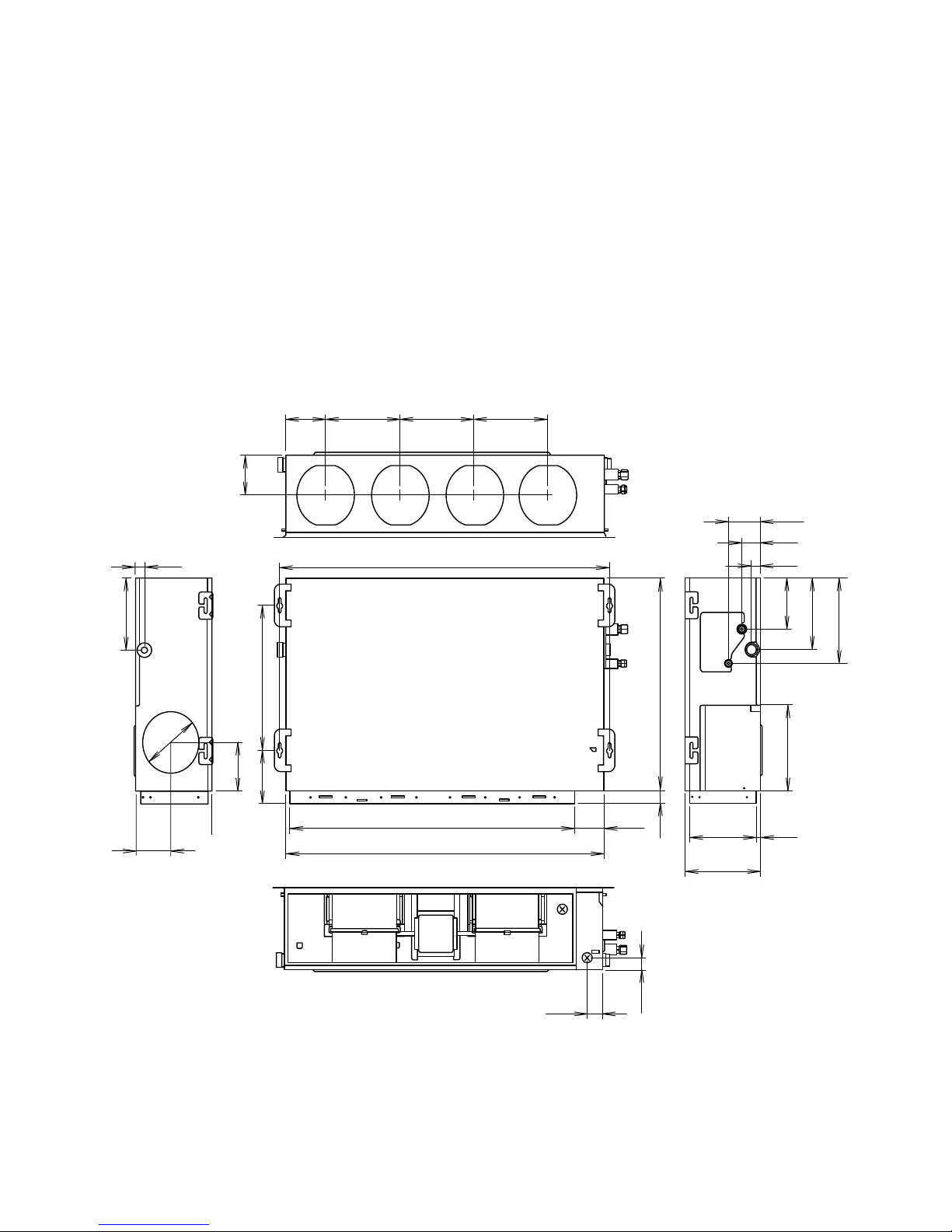
DIMENSIONS
Unit : mm
INDOOR UNIT
2008.06.26
2
1,135
1,177
1,015
139
264 264 264
107
32
114
66
32
54
240
281
168
283
477
700
173
161
40
39
240
132
240
16
121
270
Page 4

OUTDOOR UNIT
Unit : mm
2006.09.29
3
Top view
Front view
Side view
Bottom view
Drain pipe
mounting place
( 20)
189
177
347
540
31566790
121
578
320
10
184
4- 10mm hole
Air flow
Page 5

REFRIGERANT SYSTEM DIAGRAM
OUTDOOR UNIT
INDOOR UNIT
2006.10.23 4
StrainerStrainer
4-Way
valve
2-Way
valve
3-Way
valve
Muffler
Muffler
Expansion
valve
Compressor
Accumulator
Heat exchanger
Heat exchanger
Cool
Heat
: THERMISTOR (COMPRESSOR TEP.)
: THERMISTOR (PIPE TEP.)
: THERMISTOR (ROOM TEP.)
: THERMISTOR (DISCHARGE TEP.)
: THERMISTOR (HEAT EXCHANGER MED TEP.)
: THERMISTOR (HEAT EXCHANGER OUT TEP.)
: THERMISTOR (OUTDOOR TEP.)
Refrigerant pipe diameter
Liquid : 1/4" (6.35 mm)
Gas : 5/8" (15.88 mm)
Page 6

BLACK
WHITE
RED
BROWN
YELLOW
WHITE
BLACK
RED
GREEN
GREEN
WHITE
WHITE
WHITE
RED
BLACK
GRAY
GRAY
GRAY
GRAY
GRAY
GRAY
GRAY
GRAY
GRAY
GRAY
GRAY
BLACK
BLACK
GRAY
GRAY
1 2
34567
8
1 2
34567
8
1
2
3 4 567
8
1 2
34567
8
1 2
3
1
2
3
1 2
3
1
2
3
1
2
3
1
2
1 2
1
2
1 2
1
2
3
4
5
6
7
8
1
2
3
4
5
6
7
8
1
2
3
4
5
6
1
2
3
4
5
6
1
2
1
2
3
4
5
6
7
1
2
3
1
2
3
1
2
1
2
1
2
3
1
2
3
4
5
1
2
3
4
5
1 2
1
2
1
2
1 2
CN7 CN8
CN5
CN4 CN1
CN104
CN101
CN102
CN103
CN108
E101 E102
W105
W101
W102
CN106
CN105
CN10
CN11CN9
CN12
CN14
CN13
CN6
CN3
TERMINAL
TERMINAL
TO REMOTE CONTROL
TO OUTDOOR UNIT
COIL
ROOM THERMISTOR
PIPE THERMISTOR
1
2
3
1 2
3
CONTROLLER
PCB ASSY
( MAIN PCB )
F101
FUSE
3.15A
250V
POWER SUPPLY
PCB ASSY
F M
FAN
MOTOR
GREEN
/ YELLOW
1
2
3
2008.07.25 5
INDOOR UNIT
ARYA24LATU
CIRCUIT DIAGRAM
Page 7

GRAY
GRAY
BLACK
BLACK
RED
WHITE
BLACK
RED
WHITE
BLACK
YELLOW
BROWN
WHITE
BLACK
RED
GRAY
GRAY
GRAY
GRAY
GRAY
GRAY
GRAY
GRAY
GRAY
GRAY
GRAY
1 2 3 4 5 6 7 8 1 2 3
1
2 3
4 5 6 781
2 3
1
2 3
4 5 6 781
2 3
1
2 3
4 5 6 781
2 3
1
2 3
1 2 1
2
1
2
1
2
1
2
1
2
2
1
2
1
2
1
1
2
3
4
5
6
7
1
2
3
1
2
3
1
2
1
2
3
1
2
3
4
5
1
2
3
4
5
1
2
3
1
2
1
2
3
4
5
6
1
2
3
4
5
6
1
2
3
4
5
6
7
1
2
3
4
5
6
7
8 8
GREEN
/ YELLOW
GREEN
GREEN
WHITE
WHITE
CN101
W105
W102
W101
CN108
CN103
CN102
CN104
E101 E102
CN105
CN106
CN4
CN1
CN5
CN7
CN8
CN12
CN11
CN9CN10
CN6
CN14 CN13 CN3
TERMISTOR
( PIPE TEMP. )
TERMISTOR
( ROOM TEMP. )
TERMINAL
TERMINAL
F101
1 2 3
1 2 3
TO OUTDOOR UNIT
TO REMOTE CONTROL
COIL
FUSE
3.15A 250V
F M
FAN MOTOR
CONTROLLER
PCB ASSEMBLY
POWER SUPPLY
PCB ASSEMBLY
4
5
6
1
2
3
4
5
CN2
2009.06.29 6
INDOOR UNIT
ARYF24LBTU
Page 8

BLACK
RED
WHITE
YELLOW
BLUE
RED
WHITE
BLACK
RED
BROWN
BLUE
ORANGE
YELLOW
WHITE
BLACK
BLACK
BLACK
BLACK
BLACK
BLACK
BLACK
WHITE
WHITE
RED
BROWN
BROWN
BROWN
BROWN
BLACK
BLACK
WHITE
RED
YELLOW
YELLOW
GREEN
BLACK
BLACK
BLACK
1
2
3
4
5
6
1
2
3
4
5
6
1
2
3
4
5
6
1
2
3
4
5
6
1
2
3
1
2
3
1
2
3
1
2
3
121
2
121
2
1
2
3
4
1
2
3
4
12
1
2
1
2
3
1
2
3
RED
WHITE
BLACK
CN71
CN73
CN72
CN70
W4
W2
W1
W3
W11
W10
CN40
CN801
W7
W8
W9
CN30
4-WAY
VALVE
4WV
PMV
F M
S (S)
C (T)
R (R)
FAN MOTOR
EXPANSION
VALVE
COMPRESSOR
C M
REACTOR
PIPE
THERMISTOR
DISCHARGE PIPE
THERMISTOR
COMPRESSOR
THERMISTOR
PIPE ( MID )
THERMISTOR
OUTDOOR
THERMISTOR
FUSE
250V 5A
TERMINAL
TO INDOOR UNIT
POWER SOURCE
2
( N )
1 3 L
N
FUSE 250V 20A
CONTROLLER PCB ASSY
2008.07.25 7
OUTDOOR UNIT
Page 9

PCB Circuit
Diagrams
not available at time of publication
Page 10

Troubleshooting at the remote control LCD
This is possible only on the wired remote control.
[ SELF-DIAGNOSIS ]
If an error occurs, the following display will be shown.
("EE" will appear in the set room temperature display.)
Unit number
Error code
Ex. Self-diagnosis
S UMOTUWETH F R
S A
Code Error contents
Indoor signal error
Wired remote controller abnormal
Indoor room temperature sensor error
Indoor heat exchanger temperature sensor (middle) error
Indoor heat exchanger temperature sensor (inlet) error
Float switch operated
Outdoor discharge pipe temperature sensor error
Outdoor heat exchanger temperature sensor (outlet) error
Outdoor temperature sensor error
Compressor temperature sensor error
2-way valve temperature sensor error
3-way valve temperature sensor error
Outdoor heat exchanger temperature sensor (middle) error
Indoor manual auto switch abnormal
Power supply frequency detection error
IPM protection
CT error
Compressor location error
Outdoor fan error
Connected indoor unit abnormal
Outdoor unit computer communication error
Indoor fan abnormal
Discharge temperature error
Exessive high pressure protection on cooling
4-way valve abnormal
Pressure switch abnormal
Compressor temperature error
Active filter abnormal
PFC circuit error
01
13
26
27
00
02
04
28
09
0C
06
0A
15
1d
1E
29
20
2A
17
18
1A
1b
1F
1c
12
0F
24
2c
16
2b
19
25
If "CO" appears in the unit number display, there is a remote controller
error. Refer to the installation instruction sheet included with the remote
controller.
2006.10.23 16
ERROR CONTENTS
REMOTE CONTROL UNIT
Page 11

2008.07.25 17
OUTDOOR UNIT
Error contents
Thermistor malfunction
Abnormal discharge temperature
Current surge protection
CT abnormality
Compressor position detection malfunction
PAM voltage abnormality
Timer short
Compressor temperature protection (permanent stop)
PFC surge protection (permanent stop)
Fan malfunction
LED
on 0.1 sec / off 0.1 sec
on
on 0.5 sec / off 0.5 sec
on 2.0 sec / off 2.0 sec
on 0.1 sec / off 2.0 sec
on 5.0 sec / off 0.1 sec
on 1.0 sec / off 1.0 sec
on 2.0 sec / off 5.0 sec
on 5.0 sec / off 2.0 sec
on 5.0 sec / off 5.0 sec
Page 12
Insulation
Insulation
Control Bo
x
Insulation
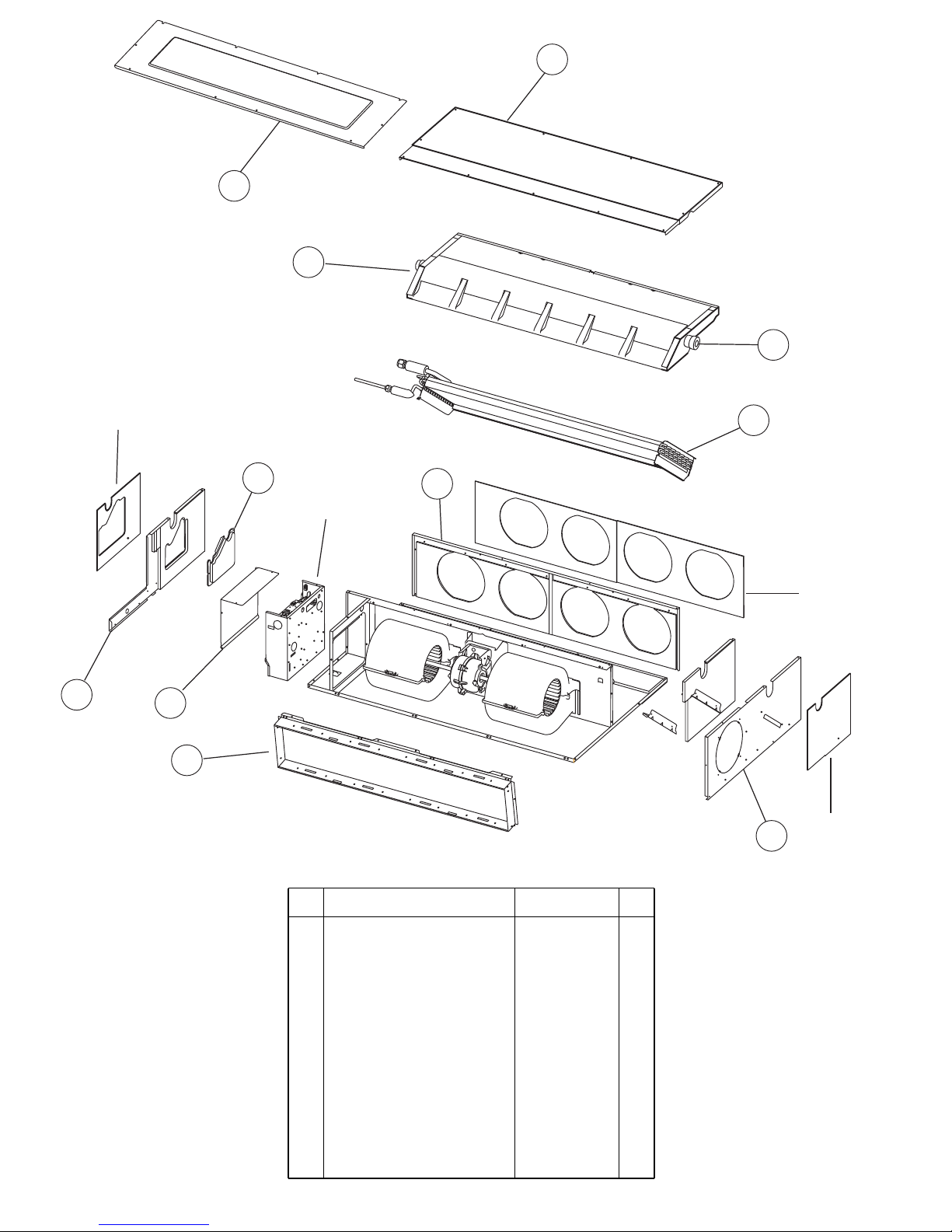
PARTS
INDOOR UNIT
2007.10.29 18
1
2
3
4
5
10
11
7
9
8
6
7 Control Cover-A Sub Assy 9374516018
10 Cabinet L Sub Assy 9374509010
9 Cabinet R Sub Assy 9374508013
1 Intake Cover Sub Assy 9374512010
6 Outlet Panel Sub Assy 9374510016
5 Evaporator Assy 9374518012
3 Drain Pan Sub Assy 9374513017
2 Main Panel Sub Assy 9374511013
11 Intake Frame Assy 9374216017
4 Drain Cap 9356541007
8 Bracket (pipe) Sub Assy 9374514014
Ref. Description Part number
Page 13

30
25
26
27
27
29
29
28
INDOOR UNIT
22
23
24
21
2007.10.29 19
25
23 Casing B 9374234011
Bracket Motor Assy A 9374230020
24 Sirocco Fan Assy 9356531039
29 Rubber 9385102002
21 Base Sub Assy 9374504015
22 Separate Wall Assy 9374228010
30 Bracket (Eva.) R 9374207015
28 Motor, Induction 9602433018
26 Bracket Motor Assy B 9358591000
27 Bracket Motor C 9358594001
Ref. Description Part number
-- Bracket (Eva.) L 9374208012
Page 14
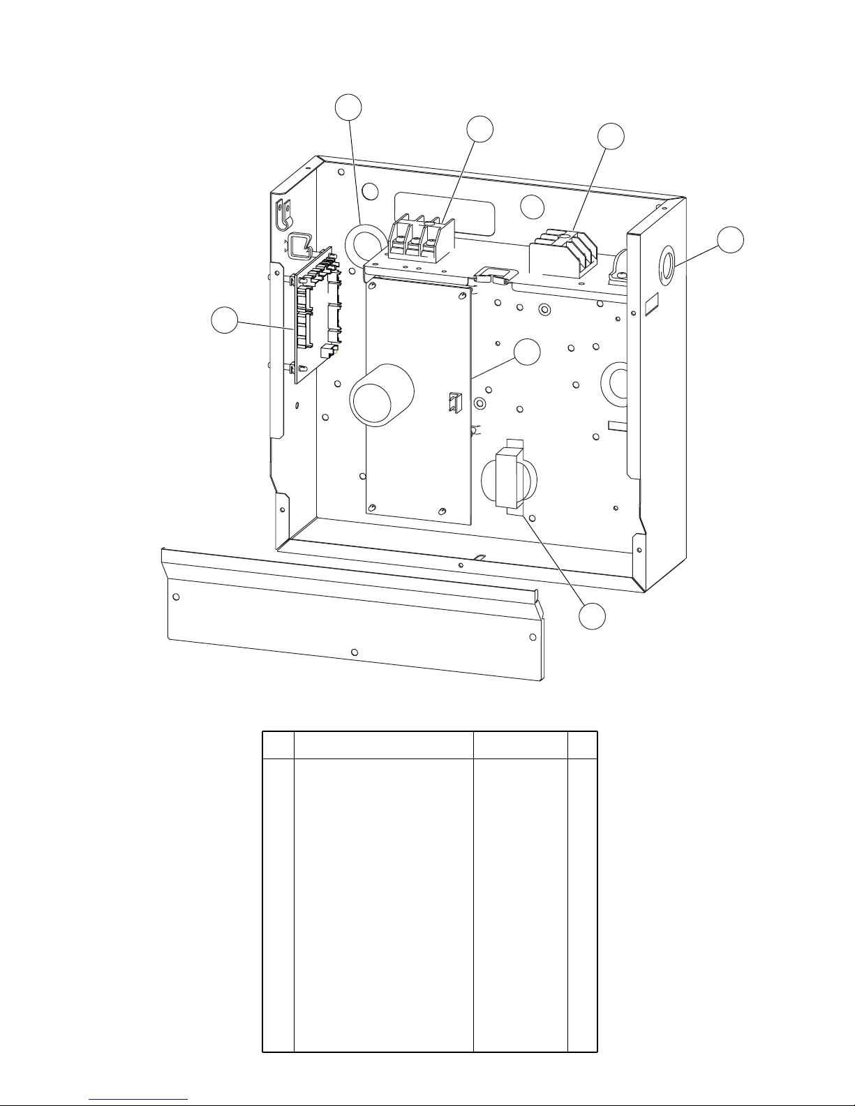
INDOOR UNIT
2009.06.29
20
32
35
34
33
36
31
37
31 Controller PCB Assy (LATU) 9707393064
32 Cap (Power) 9352173011
33 One Touch Bush 9374407019
34 Terminal 3P 9703345012
35 Terminal 3P 9306489045
36
Power Supply PCB Assy (LATU)
9707398045
31 Controller PCB Assy (LBTU) 9707393491
36
Power Supply PCB Assy (LBTU)
9707398144
37 Reactor Assy 9707457018
-- Room Thermistor 9703299025
-- Pipe Thermistor 9703297021
-- Remote Control 9372266199
-- Wire Assembly 9372714010
Ref. Description Part number
Page 15

2008.07.29 21
1
2
9
7
5
6
3
4
OUTDOOR UNIT
PARTS
8
1 Top Panel Assy
3 Cabinet Assy
4 Blow Down Grille
5 Cabinet Right Assy
6 Fan Ring
7 Grip
9 Protective Net
8 Emblem
2 Cover (Switch) Assy
9309230057
9314809019
9309237032
9308884015
9309236028
9308885012
9308880017
9315033017
9315210012
Ref. Description Part number
Page 16

2007.10.25 22
18
19
41
10
20
32
13
35
40
21
17
14
11
34
16
15
OUTDOOR UNIT
37
38
37
39
22
10 4-Way Valve
11 Pulse Motor Valve Assy
13 Condenser Assy
14 Thermistor Spring A
15 Thermistor Spring
16 Propeller Fan
17 Nut
18 Motor Bracket
19 Separator Assy
20 Base Assy
21 3-Way Valve Assy
22 2-Way Valve Assy
32 Expansion Valve Coil
34 Fan Motor
35 Compressor Assy
Reactor Assy
39 Solenoid Coil
41
Thermistor Assy37
38
Heat Exchanger Thermistor
Outdoor Thermistor--
Ref. Description Part number
40 Compressor Thermistor
9900163013
9315310019
9315302014
9900403010
313728262708
9357804002
9309909014
9304902003
9308872029
9312971015
9315296030
9315414014
9313062019
9900057039
9602451012
9315297037
9970055010
9900354015
9900148027
9900210045
Condenser Assy B-- 9315303011
9900156046
Page 17

2009.07.09
23
26
42
43
30
28
29
27
OUTDOOR UNIT
26
Inverter PCB Assy (AOYA)
29 Fuse
Terminal42
30 Fuse
27 Fuse Holder
28 Fuse Holder
Ref. Description Part number
Inverter Case Assy43
9707427028
26
Inverter PCB Assy (AOYB)
9707427127
0600382018
9703874031
0600372163
0501454012
0501456016
9315690012
Page 18

ACCESSORIES
INDOOR UNIT
Name and Shape
Hanger
Special nut A
(large flange)
Special nut B
(small flange)
Coupler heat
insulation (large)
Coupler heat
insulation (small)
Q'ty
4
4
4
1
1
Application
(part number)
For suspending the indoor
unit from ceiling
(9356563009)
For suspending the indoor
unit from ceiling
(313005446653)
(313005446759)
For indoor side pipe joint
(large pipe)
(9378173569)
For indoor side pipe joint
(small pipe)
(9378173521)
Name and Shape Q'ty
Application
(part number)
Binder
Drain hose
insulation
1
(small)
1
For remote control and
remote control cord
(313361275805)
1
(large)
For fixing the drain hose
(312300787605)
Insulates the drain hose
and vinyl hose
(313806217708)
OPTIONAL PARTS
When connecting the square duct and round duct,
use the optional square flange or round flange and flexible duct.
Square flange Round flange
Model name : UTD-SF045T (P/N 9098180007) Model name : UTD-RF204 (P/N 9093160004)
Flexible duct Long-life filter
Model name : UTD-RD202 (P/N 9074165004) Model name : UTD-LF25NA (P/N 9079892004)
Remote sensor
Model name : UTD-RS100 (P/N 9072619004)
External control set
Model name : UTD-ECS5A (P/N 9077359004)
Drain pump unit
Model name : UTZ-PX1BBA (P/N 9052976004)
Receiver unit
Model name : UTY-LRHX1 (P/N 9048213007)
40 mm
204 mm
1065 mm
L 2 m
507 mm
239 mm
85 mm
195 mm
205 mm
22
5
mm
23
5
mm
200 mm
1
For outdoor unit
drain piping work.
9303029015
Drain pipe
Q'ty
OUTDOOR UNIT
Name and Shape
Part numberApplication
2008.07.25 24
Remote
control
1
For air conditioner
operation
(9372266199)
Remote
controll cord
1
For connecting a
remote control
(9372714010)
Screw
(M4 x 16)
2
For installing a
remote control
(0700181108)
Page 19

0708G3257
 Loading...