

Page 1

Indoor unit Outdoor unit
ARG45FUAN
AOG45FMAXT
ARG45UUAN AOG45UMAXT
ARY45FUAN AOY45FMAXT
ARY45UUAN AOY45UMAXT
CONTENTS
SPECIFICATIONS . . . . . . . . . . . . . . . . . . .
1
DIMENSIONS . . . . . . . . . . . . . . . . . . . . . .
3
REFRIGERANT SYSTEM DIAGRAM . . . .
5
CIRCUIT DIAGRAM . . . . . . . . . . . . . . . . .
6
8
ERROR DISPLAY. . . . . . . . . . . . . . . . . . .
INDOOR PCB CIRCUIT DIAGRAM. . . . . .
10
OUTDOOR PCB CIRCUIT DIAGRAM . . .
11
DISASSEMBLY ILLUSTRATION . . . . . . .
12
PARTS LIST . . . . . . . . . . . . . . . . . . . . . .
21
STANDARD ACCESSORIES . . . . . . . . .
23
SPLIT TYPE
AIR CONDITIONER
DUCT TYPE (50Hz)
Page 2
2005.12.06 1
SPECIFICATIONS
TYPE COOLING COOLING & HEATING
INDOOR UNIT
ARG45FUAN, ARY45FUAN ARG45UUAN, ARY45UUAN
OUTDOOR UNIT
AOG45FMAXT, AOY45FMAXT AOG45UMAXT, AOY45UMAXT
COOLING CAPACITY
(kW)
12.7 12.7
HEATING CAPACITY
(kW)
------- 14.3
POWER SOURCE (V) 400
FREQUENCY (Hz) 50
RUNNING
CURRENT
COOLING 7.70
7.70
(A)
HEATING ------- 7.70
INPUT WATTS (kW)
COOLING 4.38 4.38
HEATING ------- 4.39
E.E.R. (kW /kW)
COOLING 2.90 2.90
HEATING -------
3.26
STARTING CURRENT
(A)
67
MOISTURE REMOVAL
( /hr)
510
TYPE
Hermetic type, 2 pole, Single phase,
Induction motor, Rotary
DISCRIMINATION
BN52YEAMT
REFRIGERANT R410A (g)
3,400 3,400
DISCRIMINATION MFA-45PTAT
HIGH 1,280
INDOOR
MED 1,200
FAN SPEED
LOW 1,100
(r.p.m.)
DISCRIMINATION
MFB-30PTT
OUTDOOR 780
AIR FLOW
INDOOR 2,450
(m3/ h)
OUTDOOR 6,100
DIMENSIONS
INDOOR 270 x 1,135 x 700
H x W x D (mm)
OUTDOOR 1,165 x 900 x 330
WEIGHT
INDOOR 52 / 45
GROSS / NET
(kg)
OUTDOOR
116 / 109
120 / 113
MAX PIPE LENGTH / HEIGHT
(m)
50 / 30
REMOTE CONTROLLER TYPE WIRED
ELECTRICAL DATA
COMPRESSOR
Note : The above list shows values at the external static pressure of
98Pa (10mm Ag), setting the fan speed high notch.
Note : The above list shows values at the external static pressure of
98Pa (10mm Ag), setting the fan speed high notch.
Page 3
PIPE LENGTH
20 m ( 66 ft ) 3,400 g ( 119.9 oz )
FULL CHARGE
30 m ( 99 ft ) 3,800 g ( 134.0 oz )
AMOUNT
40 m ( 132 ft ) 4,200 g ( 148.2 oz )
50 m ( 165 ft ) 4,600 g ( 162.3 oz )
ADDITIONAL REFRIGERANT 40 g / m ( 0.424 oz / ft )
TYPE COOLING COOLING & HEATING
INDOOR UNIT
ARG45FUAN, ARY45FUAN ARG45UUAN, ARY45UUAN
OUTDOOR UNIT
AOG45FMAXT, AOY45FMAXT AOG45UMAXT, AOY45UMAXT
NOISE LEVEL
HI-SPEED
44
INDOOR UNIT
MED-SPEED (dB)
(dB)
(dB)
42
LO-SPEED
40
OUTDOOR UNIT
(dB)
54 COOL 54 / HEAT 56
Note : Static pressure : 100Pa
Duct length : Inlet 1m, Outlet 2m
When you dismantle indoor units which are installed,
take care not to make parts fall down, especially motors.
2005.12.06 2
Page 4
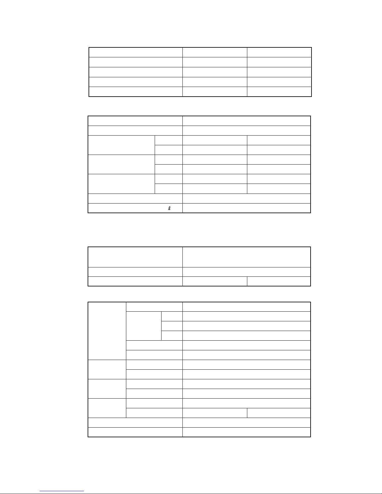
DIMENSIONS
(Unit : mm)
Models : ARG45FUAN, ARG45UUAN
ARY45FUAN, ARY45UUAN
INDOOR UNIT
2005.12.05 3
1,135
1,177
1,015
139
264 264 264
107
32
114
66
32
54
240
281
168
283
477
700
173
161
40
39
240
132
240
16
121
270
Page 5
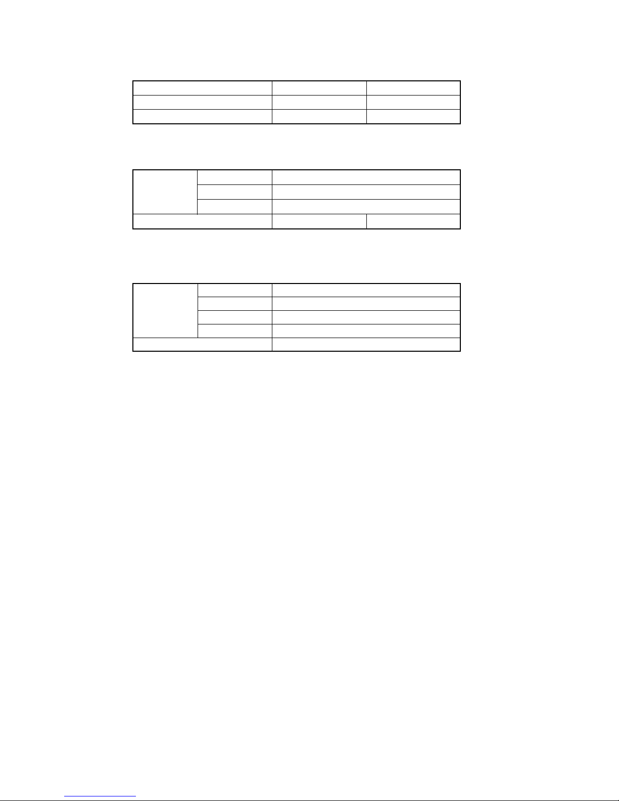
Models : AOG45FMAXT, AOG45UMAXT
AOY45FMAXT, AOY45UMAXT
(Unit : mm)
OUTDOOR UNIT
2005.12.05 4
3177900 330 12
9
21
1165
400
650
370
Air Flow
151
170
99
196
Page 6
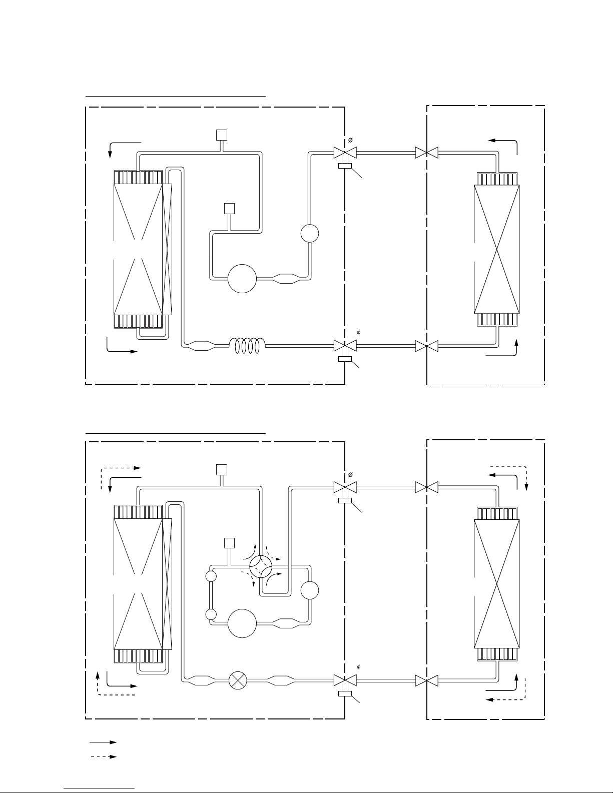
REFRIGERANT SYSTEM DIAGRAM
Models : ARG45FUAN / AOG45FMAXT
ARY45FUAN / AOY45FMAXT
Models : ARG45UUAN / AOG45FMAXT
ARY45UUAN / AOY45FMAXT
2005.12.06 5
: COOL
: HEAT
Refrigerant Pipe
19.05mm (3/4")
Refrigerant pipe
9.52mm (3/8")
INDOOR UNIT
Charging
Valve
Charging Valve
OUTDOOR UNIT
Compressor
Strainer
Strainer
Expansion Valve
Strainer
Condenser
4-way
Valve
Muffler x 2
Pressure
Check Valve
High
Pressure
Switch
Accumulator
Refrigerant Pipe
19.05mm (3/4")
Refrigerant pipe
9.52mm (3/8")
INDOOR UNIT
Evaporator
Charging
Valve
Charging Valve
OUTDOOR UNIT
Compressor
Strainer
Strainer
Condenser
Pressure
Check Valve
High
Pressure
Switch
Evaporator
Accumulator
Cappillary Tube
Page 7

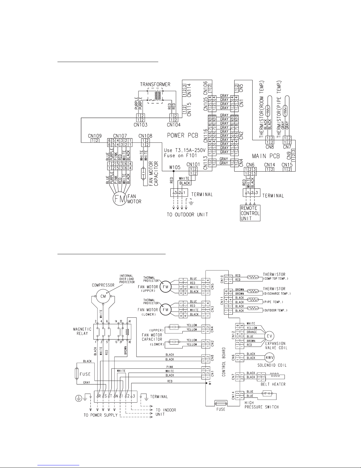
CIRCUIT DIAGRAM
Models : ARG45FUAN, ARY45FUAN
Models : AOG45FMAXT, AOY45FMAXT
2005.12.06 6
Page 8
Models : ARG45UUAN, ARY45UUAN
Models : AOG45UMAXT, AOY45UMAXT
2005.12.05 7
GRAY
U(T1)
W(T3)
V(T2)
BROWN
Page 9

JP
Delay
off
+2 deg.
commercial
Function
Commercial mode
on
0 deg.
normal
No delay
Fan delay change (heating operation)
JP3
Room temp. correction (cooling)
JP
JP1
JP2
SW1 & SW2
SW1-1 Fan changer
on offSW Function
SW2-3
Room temp. correction (heating)
SW2-1
SW1-2
SW2-2
not auto
0 deg.
-
pulse
auto
+4 deg.
-
- -
edge
Auto restart
Ex. signal function changer
Fan changer
SW1-3 SW1-4 Wired remote controller
Remote control unit custom code switching
on
on off
off
ononoff
off
weekly type
EZ-09503HSE-R series
EZ-098YHSE-R series
"with thermistor" type
Wireless
B type
D type
C type
A type
2005.12.06 8
INDOOR PCB CIRCUIT DIAGRAM
9
8
7
6
5
4
3
2
1
10
11
12
13
14
15
16
5V
5V
R41 1.0K <1/10W>
5V
C40
0.01
<F>
C2
10/
25V
+
12V
1
2
3
4
5
6
7
8
710
2
3
4
5
1
2
3
4
5
1
2
1
2
1
5V
BLACK
BLACK
GRAY
GRAY
1
3
2
1
2
1
2
1
2
3
1
2
3
VCC
VOUT
GND
SUB
NC
5
4
3 1
2
5V
5V
C12
0.1
<F>
I C9
BD4742G
D1
DAN202K
C37
0.01
<F>
C11
0.1
<F>
X1
CSTS0500MG03-T
2
1
70
69
X1
X2
12
13
16
17
42
41
43
44
50
63
19
20
21
22
23
24
29
26
27
28
9
8
25
30
46
45
33
67
4
7
75
68
74
10
11
6
5
3
2
1
65
66
73
80
79
78
76
77
59
58
57
56
55
54
53
52
71
14
15
40
36
37
38
39
62
61
51
47
48
49
72
35
31
32
34
18
64
60
RESET
P03
P27
P56
P55
P54
R72
10K
<1/10W>
R80
10K
<1/10W>
R79 1.0K
<1/10W>
C10
0.1
<F>
5V
R39
10K
<1/10W>
C36
0.01
<F>
R40 1.0K
<1/10W>
5V
C13
0.1
<F>
5V
I C7
BR93LC46
R45 - R47
10K <1/10W> x 3
NC
R48 10K <1/10W>
P57
XT2
P35
P34
P33
P37
P00
P23
P24
P64
P60
P61
P62
P63
P01
I C
P120
P121
P127
P126
P125
P124
P123
P122
P14
P13
P12
P10
P11
P04
P05
P07
P15
P16
P17
P130
P131
P72
P20
VDD0
VDD1
AVRF0
AVRF1
AVSS
VSS0
VSS1
P31
P32
P53
P46
P70
P71
P51
P50
P47
P52
P45
P44
P43
P42
P41
P40
P02
P36
P30
P67
P66
P65
P21
P22
P25
P26
C27
0.1
<F>
C26
0.1
<F>
C25
0.1
<F>
C24
0.1
<F>
R21 - R24
1.0K <1/10W> x 4
5V
C28 - C31
0.01 <F> x 4
5V
14V
R33 - R36
1.0K <1/10W> x 4
10K <1/10W> x 4
R29 R30 R32R31
BZ1
R37 1.0K
<1/10W>
R38 1.0K
<1/10W>
I C3 (1/7)
uPA2003GR
12 5
1
2
3
4
5
1
2
4
3
2
1
8
4
2
15C
1
2
3
45
6
1
342
1
9
3
7
6
5
4
8
2
10
K104
SSR
I NT
1
23
4
3
2
1
3
1
2
2
3 1
O
I
G
O
I
G
2
1
32
1
4
2
1
3
2
1
1
2
4
3
1
2
4
3
1
2
3
4
1
2
2
1
1
2
5V
5V
C21 - C23
0.1 <F>
x 3
C17 - C20
0.1 <F> x 3
5V
+
C3
0.01
<F>
5V
C1
100/
6.3V
5V
5V
14V
PC103
TLP621
<GB>
14V
12V
5V
SW2
R15 - R17
10K <1/10W>
x 3
R18 - R20
1.0K <1/10W> x 3
SW1
14V
I C5 (7/7)
uPA2003GR
JM4
5V
14V
I C3 (3/7)
uPA2003GR
14V
D3
D1FS4A
D2
DA226U
12V
12V
14V
REMOTE CONTROL UNIT
TERMINAL BOARD
EARTH WIRE
3
2
1
UL1430 AWG22 BLACK
UL1430 AWG22 RED
UL1430 AWG22 WHITE
R43 R44
10K <1/10W> x 2
I C3 (1/7)
uPA2003GR
R71
10K
<1/10W>
R68
15.4K
<1/10W>
R69
28K
<1/10W>
R70
10K
<1/10W>
I C3 (1/7)
uPA2003GR
I C6-2
BA10393F
I C6-1
BA10393F
R67 390
<1/10W>
611
2
3
1
7
6
5
+
+
-
-
9
8
15
14
13
2
3
4
1
2
3
6
8
4
7
5
CS
SK
D I
NC
VCC
DO
NC
GND
R42 47
<1/10W>
C41
1000P
<R>
C39
0.01
<F>
R50 10K
<1/10W>
R49 10K
<1/10W>
R62 - R64
10K <1/10W> x 3
R57 - R59
1.0K <1/10W> x 3
C14
0.1
<F>
C15
0.1
<F>
C16
0.1
<F>
C8
0.1
<F>
C9
0.1
<F>
R60 1.0K
<1/10W>
R61 1.0K
<1/10W>
14V
R65
10K
<1/10W>
R66
49.9K
<1/10W>
5V
JM1
JM2
JM3
COMMERCIAL MODE
ROOM TEMPERATURE CORRECTION
( COOLING OPERATION )
FANDELAY CHANGE
( HEATING OPERATION )
10K <1/10W> x 3R3 R2 R1
R4 1.0K <1/10W>
R6 1.0K <1/10W>
R5 1.0K <1/10W>
CN8
B2B-XASK-1-A
WHITE
CN7
B2B-XAKK-1-A BLACK
ROOM TEMPERATURE THERMISTOR
PIPE TEMPERATURE THERMISTOR
CN11
B5B-XASK-1-A
WHITE
LOUVER ( UP / DOWN )
CN12
B5B-XARK-1-A
RED
LOUVER ( RIGHT / LEFT )
CN13
B8B-XASK-1-A
WHITE
INDICATOR
CN6
B3B-XAKK-1-A
BLACK
CN14
B02B-PAMK-1
GREEN
FRESH AIR
HEATER
CN15
B02B-PA0K-1
ORANGE
CN9
B3B-XARK-1-A
RED
FLOAT SWITCH
FEED BACK
CN10
B3P-VH-B
WHITE
SW3
R25 - R28
10K <1/10W>
x 4
FANCAPACITOR
15uF
440V
CN108
B2P3-VH-B-Y
YELLOW
CN3
B5P-SHF-1AA
WHITE
TEST
CN107
B6P11-VH-B
WHITE
CN109
B2P3-VH-B-E
BLUE
DRAIN PUMP
1
2
14V
CR101
120 / 0.2
K104
G5N-1A
K102
G5SB-14
DC12V
K103
G5SB-14
DC12V
K101
G5SB-14
DC12V
K108
G5N-1A
CR104
120 / 0.2
CN111
B2P3-VH-B
WHITE
12
CN101
B2P3-VH-B-C
BLACK
AC I N MAGNETIC
RELAY
NL
FH101
FH102
F101
3.15A
<BET>
VA10 1
470V
K110
G2R-1A
DC12V
14V
K108
K103
K101
K110
K102
1
9
3
7
6
5
4
8
2
10
UL1430 AWG26 GRAY
UL1430 AWG26 GRAY
UL1430 AWG26 GRAY
UL1430 AWG26 GRAY
UL1430 AWG26 GRAY
UL1430 AWG26 GRAY
UL1430 AWG26 GRAY
UL1430 AWG26 GRAY
UL1430 AWG26 GRAY
UL1430 AWG26 GRAY
RELAY DRIVE
CN116
B10B-PASK-1
WHITE
CN2
B10B-PASK-1
WHITE
5V
Q2
DTC124EKA
C33
0.01
<F>
C32
0.01
<F>
R78 390
<1/10W>
R77 390
<1/10W>
1
2
3
8
16
14
12
9
11
6
4213
15
3
1
5
8
9
15132
4
14
16 1
3
1
2
3
2
1
2
1
10
7
2
1
1
16
C35
0.01
<B>
R73
10K
<1/10W>
R74 1.0K <1/10W>
5V
R53
10K
<1/10W>
C38
0.01
<F>
R55
10K
<1/10W>
R56 1.0K <1/10W>
I C2 (1/7)
uPA2003GR
I C3 (1/7)
uPA2003GR
C34
0.01
<F>
R54 180
<1/10W>
14V
14V
Q1
DTA143
I C4 (4/7)
uPA2003GR
I C2 (6/7)
uPA2003GR
B Z
3
1
FAN
MOTOR
OUTDOOR UNIT
2(N)
JM101
JM102
5V
C113
0.01
<B>
R105 1.0K
<1/4W>
R106
10K
<1/4W>
D104
1SR139-600
R104 56K
<RS-1W>
PC101
TLP621
<GB>
UL1015 AWG20 WHITE
UL1015 AWG20 WHITE
UL1015 AWG22 BLACK
UL1015 AWG22 WHITE
UL1015 AWG22 RED
UL1015 AWG22 PINK
UL1015 AWG22 PURPLE
UL1015 AWG22 BLUE
UL1015 AWG18 GRAY
UL1015 AWG18 WHITE
UL1015 AWG18 BLACK
TERMINAL BOARD
UL1015 AWG22 PURPLE
UL1015 AWG22 PURPLE
SECONDARY
PRIMARY
CN103
B2P3-VH-B-R
RED
POWER TRANSFORMER
EZ-0970WWE-T
5V
12V
C112
0.1
<F>
C111
10/
25V
+
I C101
NJM7805
I C102
NJM7812
PC102
TLP621
<GB>
C114
0.01
<B>
FL102
BL02RN1
R108
330 <1/4W>
FL101
BL02RN1
14V
Q101
2SD1932
C109
10/
25V
+
D102
MTZJ15C
D101
D2SB20
R102
10K
<1/4W>
C107
1000
/50V
+
R103
1.0K
<1/2W>
C108
10/
25V
+
CN104
B2B-XARK-1-A
RED
JM103
UL1430 AWG22 RED
UL1430 AWG22 RED
UL1430 AWG26 GRAY
UL1430 AWG26 GRAY
UL1430 AWG26 GRAY
UL1430 AWG26 GRAY
CN105
B04B-PASK-1
WHITE
DC SUPPLY
CN1
B04B-PASK-1
WHITE
CN114
B3B-XH-AM
WHITE
EX. I N
EX. OUT
CN115
B3B-XH-AM
WHITE
5V
R107 330 <1/4W>
5V
12V 14V
R76 10K
<1/10W>
R75 10K
<1/10W>
CN106
B02B-PAKK-A
BLACK
EX. SIGNAL
CN5
B02B-PAKK-1
BLACK
SERIAL
CN4
B02B-PARK-1
RED
NEW SERIAL
CN16
B02B-PASK-1
WHITE
3
2
1
6
5
4
4
3
2
1
8
7
6
5
REMTE CUSTOMO
REMOTE CUSTOM
FAN SWITCHING
FAN SWITCHING
EX. SIGNAL FUNCTION SWITCHING
ROOM TEMPERATURE CORRECTION
( HEATING OPERATION )
AUTO RESTART
R11 - R14
10K <1/10W> x 4
R7 - R10
1.0K <1/10W> x 4
C4
0.1
<F>
C42 - C43
0.1 <F> x 2
I C 1
uPD780058BGK
-A42-9EU-A
CONTROLLER PCB ASSEMBLY ( MAIN PCB )
K03BZ-0408WSE-C1
POWER SUPPLY PCB
K04CW-0401WSE-P0
EX. SIGNAL
FAN CHANGER
FAN CHANGER
Models : ARG45FUAN
ARY45FUAN
Page 10

5V
I C 103 H I 2002
14V
VA103
470V
18
14
10
4
3
2
5
1
K101
G2R-1A
DC12V
K101
G5SB-14
DC12V
14V
K104
G5N-1A
K102
G5SB-14
DC12V
K103
G5SB-14
DC12V
W105
SERIAL
CR101
120 / 0.2
TERMINAL BOARD
CN113
B02B-PARK-1
RED
1
2
2
1
2
1
1
1
2
2
3
3
O I
O I
G
G
4
3
2
1
1
2
3
4
3
2
1
4
3
2
1
1
2
3
4
5
6
7
8
9
10
1
2
3
4
5
6
7
8
9
10
UL1430 AWG26 GRAY
UL1430 AWG26 GRAY
UL1430 AWG26 GRAY
UL1430 AWG26 GRAY
UL1430 AWG26 GRAY
UL1430 AWG26 GRAY
UL1430 AWG26 GRAY
UL1430 AWG26 GRAY
UL1430 AWG26 GRAY
UL1430 AWG26 GRAY
K102
K110
K101
K103
K104
I NT
RELAY DRIVE
CN116
B10B-PASK-1
WHITE
CN2
B10B-PASK-1
WHITE
14V
5V
Q2
DTC124EKA
C33
0.01
<F>
14V
I C2 (6/7)
uPA2003GR
C32
0.01
<F>
2
3
1
8
16
14
12
13
11
15
9
6
4
2
5
3
1
8
15
13
4
2
14
16
9
3
1
1
3
2
2
1
2
1
2
1
10
7
1
16
+
5V
5V
C1
100/
6.3V
C3
0.1
<F>
5V
C17 - C20
0.1 <F> x 4
C21 - C23
0.1 <F> x 3
C4
0.1
<F>
5V
5V
5V
14V
R53
10K
<1/10W>
C38
0.01
<F>
R55
10K
<1/10W>
R56 1.0K <1/10W>
C34
0.01
<F>
I C2 (1/7)
uPA2003GR
I C3 (1/7)
uPA2003GR
C35
0.01
<B>
I C4 (4/7)
uPA2003GR
Q1
DTA143
R54 180
<1/10W>
5V
5V
12V
14V
SW2
R15 - R17
10K <1/10W> x 3
R18 - R20
1.0K <1/10W> x 3
C42 - C43
0.1 <F> x 2
SW1
R7 - R10
1.0K <1/10W> x 4
R11 - R14
10K <1/10W> x 4
65
66
73
80
79
78
76
77
59
58
57
56
55
54
53
52
71
14
15
40
36
37
38
39
62
61
51
47
48
49
72
35
31
32
34
18
64
60
3
69
X2
X1
70
1
P03
P27
RESET
2
P57
P54
P55
P56
XT2
P35
P34
P33
P37
P00
P01
P63
P62
P61
P60
P64
P24
P23
I C
P120
P121
P122
P123
P124
P125
P126
P127
P10
P11
P12
14V
JM4
5V
5V
5V
P14
P13
P07
P05
P04
10
6
11
5
3
2
1
74
68
75
7
4
67
33
45
46
30
25
8
9
28
27
26
29
24
23
22
21
20
19
63
50
44
43
42
41
12
13
16
17
P26
P25
P22
P21
P30
P67
P66
P65
P36
P02
P45
P44
P43
P42
P41
P40
P71
P51
P50
P47
P52
P70
P46
P53
P32
P31
P20
VDD0
VDD1
AVRF0
AVRF1
AVSS
VSS0
VSS1
P72
P131
P130
P17
P16
P15
9
8
10
11
12
13
14
15
16
7
6
5
4
3
2
1
7
10
1
2
1
2
1
2
3
4
5
1
2
3
4
5
1
2
3
4
5
6
7
8
1
2
3
1
2
1
2
1
2
3
1
2
3
1
2
3
4
5
1
2
3
6
8
4
7
5
CS
SK
D I
NC
VCC
DO
NC
GND
5V
5V
C13
0.1
<F>
R39
10K
<1/10W>
5V
C10
0.1
<F>
R79 1.0K
<1/10W>
R80
10K
<1/10W>
5V
5V
C11
0.1
<F>
R72
10K
<1/10W>
C12
0.1
<F>
C37
0.01
<F>
I C9
BD4742G
VCC
VOUT
GND
SUB
NC
D1
DAN202K
X1
CSTS0500MG03-T
R40 1.0K <1/10W>
C36
0.01
<F>
R45 - R47
10K <1/10W> x 3
I C7
BR93LC46
R48 10K <1/10W>
14V
14V
14V
I C3 (3/7)
uPA2003GR
I C3 (1/7)
uPA2003GR
8
9
15
14
13
4
3
2
6
11
1
2
3
+
-
I C6-1
BA10393F
R67 390
<1/10W>
12V
5V
R71
10K
<1/10W>
I C6-2
BA10393F
+
-
7
5
6
12V
C39
0.01
<F>
C41
1000P
<R>
R42 47
<1/10W>
12V
D3
D1FS4A
D2
DA226U
R68
15.4K
<1/10W>
R69
28K
<1/10W>
R70
10K
<1/10W>
+
C2
10/
25V
C40
0.01
<F>
I C3 (1/7)
uPA2003GR
R49 10K
<1/10W>
R50 10K
<1/10W>
R41 1.0K <1/10W>
R43
R44
10K <1/10W> x 2
I C5 (7/7)
uPA2003GR
R62 - R64
10K <1/10W> x 3
R57 - R59
1.0K <1/10W> x 3
5V
5V
R73
10K
<1/10W>
R74 1.0K
<1/10W>
R75 1.0K
<1/10W>
R76 1.0K
<1/10W>
C16
0.1
<F>
C14
0.1
<F>
C15
0.1
<F>
R60 1.0K
<1/10W>
R61 1.0K
<1/10W>
R65
10K
<1/10W>
R66
49.9K
<1/10W>
14V
C8
0.1
<F>
C9
0.1
<F>
JM1
JM3
JM2
10K <1/10W> x 3
R3
R1
R2
JM101
+
5V
12V
C112
0.1
<F>
C111
10/
25V
I C101
NJM7805
I C102
NJM7812
PRIMARY
SECONDARY
D101
D2SB20
2
3
14
2
1
JM103
UL1430 AWG22 RED
UL1430 AWG22 RED
+
+
R102
10K
<1/4W>
C107
1000
/50V
R103
1.0K
<1/2W>
C108
10/
25V
14V
Q101
2SC1932
+
C109
10/
25V
D102 MTZJ15C
CN114
B3B-XH-AM
WHITE
5V 12V 14V
CN105
B04B-PASK-1
WHITE
CN104
B2B-XARK-1-A
RED
CN103
B2P3-VH-B-R
RED
2
1
UL1015 AWG22 VIOLET
UL1015 AWG22 VIOLET
POWER TRANSFORMER
EZ-0970WWE-T
DC SUPPLY
4
3
2
1
UL1430 AWG26 GRAY
UL1430 AWG26 GRAY
UL1430 AWG26 GRAY
UL1430 AWG26 GRAY
CN1
B04B-PASK-1
WHITE
EX. I N
EX. OUT
CN115
B2B-XH-AM
WHITE
14V
FL101
BL02RN1
R107 330
<1/4W>
5V
C114
0.01
<B>
FL102
BL02RN1
PC103
TLP621
<GB>
R108
330
<1/4W>
PC102
TLP621
<GB>
JM102
FH102
FH101
F101
3.15A
<BET>
L
N
AC I N
CN101
B2P3-VH-B-C
BLACK
1
2
UL1015 AWG18 BLACK
UL1015 AWG18 WHITE
UL1015 AWG20 RED
12 5
5
1
2
3
4
8
4
2
1C
SW3
5V
C24 - C27
0.1 <F> x 4
R21 - R24
1.0K <1/10W>
x 4
R25 - R28
10K <1/10W> x 4
TEST
CN3
B5P-SHF-1AA
WHITE
1
2
3
4
5
1
2
1
2
123456
CN107
B6P11-VH-B
WHITE
CN108
B2P3-VH-B-Y
YELLOW
UL1015 AWG20 WHITE
UL1015 AWG20 WHITE
UL1015 AWG22 PURPLE
UL1015 AWG22 PINK
UL1015 AWG22 RED
UL1015 AWG22 WHITE
UL1015 AWG22 BLACK
UL1015 AWG22 BLUE
CN109
B2P3-VH-B-E
BLUE
DRAIN PUMP
5V
BZ1
R29 - R32
10K <1/10W> x 4
R33 - R36
1.0K <1/10W> x 4
C28 - C31
0.01 <F> x 4
I C3 (1/7)
uPA2003GR
R38 1.0K
<1/10W>
R37 1.0K
<1/10W>
B Z
FAN
MOTOR
FAN CAPACITOR
15.0uF
440V
2(N)
3
1
OUTDOOR UNIT
REMOTE CONTROL UNIT
EARTH WIRE
3 12
TERMINAL BOARD
CN10
B3P-VH-B
WHITE
FEED BACK
FLOAT SWITCH
CN9
B3B-XARK-1-A
RED
HEATER
CN15
B02B-PA0K-1
ORANGE
FRESH AIR
CN14
B02B-PAMK-1
GREEN
CN6
B3B-XAKK-1-A
BLACK
UL1430 AWG22 WHITE
UL1430 AWG22 RED
UL1430 AWG22 BLACK
DISPLAY
CN13
B8B-XASK-1-A
WHITE
CN12
B5B-XARK-1-A
RED
LOUVER (R / L )
LOUVER (U / D )
CN11
B5B-XASK-1-A
WHITE
CN8 B2B-XASK-1-A
WHITE
CN7 B2B-XAKK-1-A
BLACK
GRAY
GRAY
BLACK
BLACK
ROOM TEMPERATURE THERMISTOR
PIPE TEMPERATURE THERMISTOR
R4 - R6
1.0K <1/10W>
x 3
COMMERCIAL MODE
ROOM TEMPERATURE CORRECTION
( COOLING OPERATION )
FAN DELAY CHANGE
( HEATING OPERATION )
FAN SWITCHING
FAN SWITCHING
REMOTE CUSTOM
REMOTE CUSTOM
EX. SIGNAL FUNCTION SWITCHING
ROOM TEMPERATURE CORRECTION
( HEATING OPERATION )
8
7
6
5
4
3
2
1
6
5
4 1
2
3
UL1430 AWG26 GRAY
UL1430 AWG26 GRAY
EX. SIGNAL
CN106
B02B-PAKK-1
BLACK
CN5
B02B-PAKK-1
BLACK
EX. SIGNAL
SERIAL
CN4
B02B-PARK-1
RED
NEW SERIAL
CN16
B02B-PASK-1
WHITE
R77 10K
<1/10W>
R78 390
<1/10W>
NC
I C 1
uPD780058BGK
-A42-9EU-A
CONTROLLER PCB ASSEMBLY ( MAIN PCB )
K03BZ-0409HSE-C1
POWER SUPPLY PCB
K04CW-0400HSE-P0
AUTO RESTART
FAN CHANGER
FAN CHANGER
JP
Delay
off
+2 deg.
commercial
Function
Commercial mode
on
0 deg.
normal
No delay
Fan delay change (heating operation)
JP3
Room temp. correction (cooling)
JP
JP1
JP2
SW1 & SW2
SW1-1 Fan changer
on offSW Function
SW2-3
Room temp. correction (heating)
SW2-1
SW1-2
SW2-2
not auto
0 deg.
-
pulse
auto
+4 deg.
-
- -
edge
Auto restart
Ex. signal function changer
Fan changer
SW1-3 SW1-4 Wired remote controller
Remote control unit custom code switching
on
on off
off
ononoff
off
weekly type
EZ-09503HSE-R series
EZ-098YHSE-R series
"with thermistor" type
Wireless
B type
D type
C type
A type
2005.12.06 9
Models : ARG45UUAN
ARY45UUAN
Page 11

5V
5V
5V
R51
10K
<1/10W>
5V
5V
5V
5V
JM4
R54 10K <1/10W>
R55 10K <1/10W>
C34
0.1
<F>
NC
NC
5V
R22
10K
<1/10W>
C39
0.01
<F>
R21 1.0K <1/10W>
C44
0.1
<F>
NC
R42 10K
<1/10W>
I C7
NM93C46
NC
NC
NC
R43 - R45
10K <1/10W> x 3
R15 1.0K <1/10W>
R14 1.0K <1/10W>
R13 1.0K <1/10W>
R12 1.0K <1/10W>
R11 1.0K <1/10W>
C24 C21C22C23
1000P <R> x 4
X1
8.38MHz
EF0EC8384T4
2
1
3
41 40
X1 X2
28
29
30
31
32
14
13
12
11
17
16
15
27
21
22
39
36
64
26
44
47
33
48
46
49
50
51
52
53
54
55
56
24
10
34
38
42
25
9
35
43
23
18
19
45
37
20
7
8
63
62
61
60
59
58
57
2
4
5
6
1
3
P15
P14
P13
P12
P11
P33
P32
P31
P30
P24
P23
P16
P34
P35
P36
I C
RESET
P47
P17
P01
P70
P10
P71
P03
P72
P73
P74
P75
P64
P65
P66
P67
VDD1
VDD0
AVREF
XT1
GND1
AGND
GND0
AVDD
P00
P25
P20
P21
P02
XT2
P22
P56
P57
P46
P45
P44
P43
P42
P41
P40
P51
P53
P54
P55
P50
P52
NC
NC
NC
NC
NC
NC
NC
NC
NC
C25
0.01
<F>
5V
R10
4.7K
<1/10W>
C33
1000P
<R>
14V
14V
I C4-7 uLN2003
I C4-6 uLN2003
I C4-5 uLN2003
I C4-4 uLN2003
I C4-3 ULN2003
R46 10K
<1/10W>
NC
NC
NC
NC
C38
0.1
<F>
C37
0.1
<F>
5V
5V
+
C36
100/
6.3V
C16
0.1
<F>
14V
I C2
7805
R8
10K
<1/10W>
C11
0.01
<F>
D7
S3L20U
C10
1000
/25V
+
SWITCHING
TRANSFORMER
T1
ZFT19K01
1
2
3
4510
7
I
O
G
14
3
13
4
512
611
10
7
SUBNCVCC
VOUT
GND
3
4
5
2
1
CS
SK
D I
NC
VCC
DO
NC
GND
5
7
4
8
6
3
2
1
1
2
3
1
2
3
4
5
1
3
2
1
2
3
14
10
18
124
3
16
15
14
13
12
11
10
I C3-1 uPA2003
I C3-2 uPA2003
I C3-3 uPA2003
I C3-4 uPA2003
I C3-5 uPA2003
I C3-6 uPA2003
I C3-7 uPA2003
14V 14V
1
3
5
7
6
4
2
K 7
K 5
K 6
K 3
K 4
K 1
K 2
5V
C26
0.01
<F>
Q5
DTC124EKA
R9
4.7K
<1/10W>
PC1
TLP621
<GB>
D1
D1F60
C5
0.22
R16 56K
<RS - 1W>
5V
R23 10K <1/10W>
R25 10K <1/10W>
LED1 EBR3864 <RED>
LED2 EBR3864 <RED>
I C 6 HU2001
5V
5V
C32
0.1
<F>
Q3
DTC124EKA
R38 4.7K
<1/10W>
Q4
DTC124EKA
5V
R40 1.0K
<1/10W>
R39
10K
<1/10W>
5V
C31
0.01
<F>
R37 4.7K
<1/10W>
VA3
470V
C2
0.22
LF1
0.5A
<SS11V>
VA1
470V
FH1
FH2
F1
6.3A
<BET>
D8
D3SB60
1
2
3
4
C12
1000
/450V
+
Q1
2SC4236
R2 330K
<2W>
2
3
1
C13
4700P
<ECQM>
D2
1SR139-600
R3 62K
<RS - 2W>
D5
D1FL20U
+
C15
100/
6.3V
R7 330
<1/4W>
D4
D1FL20U
R4 100
<1/2W>
C14 0.047
<ECQB>
D6
MTZJ5.1B
R6 1.5
<RS - 2W>
Q2
2SC1815
R5 10K
<1/10W>
1
2
3
R1 3.3
<RC - 5W>
E
TERMINAL
250V
10A
BELT HEATER
TUBE
TUBE
BLACK
BLACK
BLACK
BLACK
5V
5V
CN10
B2B-XARK-1-A
RED
CN10-1 RED
CN10-2 RED
CN11-2 BLACK
CN11-1 BLACK
CN11-3 BLACK
CN11-4 BLACK
CN11-5 BROWN
CN11-6 BROWN
6
5
43
2
1
CN1-1
CN1-3
CN1-2
BLACK
WHITE
RED
BLUE
UL1015 AWG20 BLACK
UL1015 AWG20 BLACK
UL1015 AWG20
BLACK
UL1015 AWG20
BLACK
4-WAY VALVE
UL1015 AWG18
GRAY
BLACK
WHITE
RED
BLUE
C20
C19
C18C17
0.1 <F> x 4
R41
10K
<1/10W>
I C8
BD4742G
C35
0.1
<F>
C43
0.1
<F>
C41
0.1
<F>
C27
C30 C29 C28
0.01 <F> x 4
SW1
DSS803
R32
R29
R30
R31
1.0K <1/10W> x 4
R33 R36
R35R34
10K <1/10W> x 4
C42
0.1
<F>
C40
0.1
<F>
R50 1.0K
<1/10W>
R52 1.0K
<1/10W>
R53 10K
<1/10W>
CN14
B2P-VH-B
WHITE
ELECTRIC EXPANSION VALVE
E.E.V.
CN12
B6B-XASK-1-A
WHITE
CN12-4 UL1430 AWG24 ORANGE
CN12-1 UL1430 AWG24 RED
CN12-2 UL1430 AWG24 BROWN
CN12-3 UL1430 AWG24 BLUE
CN12-5 UL1430 AWG24 YELLOW
CN12-6 UL1430 AWG24 WHITE
CN14-1 UL1015 AWG20
BLUE
CN14-2 UL1015 AWG20
BLUE
HIGH PRESSURE SWITCH
PRES.
SW
CN11
B6B-XAKK-1-A
BLACK
THERMISTOR
CN1
B3P5-VH-B-C
BLACK
CN2
B2P3-VH-B-Y
YELLOW
CN3
B4P7-VH-B-R
RED
CN4
B2P3-VH-B-Y
YELLOW
CN5
B4P7-VH-B
WHITE
CN6
179844-1
WHITE
CN7
179844-4
YELLOW
CN8
B2P3-VH-B-R
RED
K7
FTR-F3A
K6
FTR-F3A
K5
FTR-F3A
K3
FTR-F3A
K4
G5S-1
C7 0.22
C8 0.22
R59 120
<1/2W>
R60 120
<1/2W>
K1
FTR-F3A
K2
G5S-1
C6 0.22
R58 120
<1/2W>
CN2-1
CN2-2
CN3-1
CN3-2
CN3-3
CN3-4
CN4-1
CN4-2
CN5-1
CN5-2
CN5-3
CN5-4
CN7-1
CN7-2
CN8-2
CN8-1
CN6-2
BLACK
CN6-1
BLACK
UL1015 AWG20
BLACK
WHITE
RED
BLUE
UL1015 AWG20
UL1015 AWG20
UL1015 AWG20
YELLOW
UL1015 AWG20
YELLOW
UL1015 AWG20
BLUE
UL1015 AWG20
RED
UL1015 AWG20
WHITE
UL1015 AWG20
BLACK
UL1015 AWG20
YELLOW
UL1015 AWG20
YELLOW
UL1015 AWG20
UL1015 AWG22 RED
UL1015 AWG22 PINK
UL1015 AWG22 BLACK
UL1015 AWG22 WHITE
UL1015 AWG18
UL1015 AWG18
WHITE
BLACK
UL1015 AWG14 WHITE
UL1015 AWG16 BROWN
UL1015 AWG14 RED
UL1015 AWG14 BLACK
R
S
TN
MAGNETIC
RELAY
E
R
S
T
N
1
2
3
4WV
COMP.
A
COMPRESSOR-A
POWER SOURCE
415 / 380V
50Hz
W1
INDOOR UNIT
FAN CAPACITOR-1
FAN CAPACITOR-2
FAN
MOTOR
1
FAN
MOTOR
2
I C 1
EXPANSION VALVE
FIRST PULSE SWITCHING
FOR LONG PIPING (E.E.V.)
SPARE
R20 6.65K (1%)<1/10W>
R19 6.65K (1%)<1/10W>
R18 14K (1%)<1/10W>
R17 38.3K (1%)<1/10W>
COMP. TEMP.
R100=3.43K
B50/100=4012K
PIPE TEMP.
R0=16.05K
B0/25=3873K
OUTDOOR TEMP.
R25=10.00K
B25/50=3950K
DISCHARGE TEMP.
R100=3.43K
B50/100=4012K
CONTROLLER PCBASSEMBLY
K04DF-0401HUE-C1
uPD780076GK
-649-9ET-A
C1
0.22
DIP-SW setting
SW1-1
SW1-2
SW1-3
Expansion valve first pulse switching for long piping
Spare
Spare
Function on off
Long piping mode
Normal mode
--
--
--
--
SPARE
OUTDOOR PCB CIRCUIT DIAGRAM
2005.12.06 10
Models : AOG45UMAXT
AOY45UMAXT
Page 12

CAUTION
Supply power to the crankcase heater for at least 12
hours before the start of operation in winter.
(1) Stop the air conditioner operation.
(2) Press the master control button and the fan control button si-
multaneously for 2 seconds or more to start the test run.
(3) Press the start/stop button to stop the test run.
[SELF-DIAGNOSIS]
When the error indication “E:EE” is displayed, follow the following
items to perform the self-diagnosis. “E:EE” indicates an error has
occurred.
SUMOTUWETH FR
SA
1. REMOTE CONTROLLER DISPLAY
(1) Stop the air conditioner operation.
(2) Press the set temperature buttons simultaneously for 5
seconds or more to start the self-diagnosis.
Refer to the following tables for the description of each error
code.
(3) Press the set temperature buttons simultaneously for 5
seconds or more to stop the self-diagnosis.
Error code Error contents
Communication error
(indoor unit remote controller)
Communication error
(indoor unit outdoor unit)
Room temperature sensor open
Room temperature sensor short-circuited
Indoor heat exchanger temperature sensor open
Indoor heat exchanger temperature sensor shortcircuited
Outdoor heat exchanger temperature sensor
open
Outdoor heat exchanger temperature sensor
short-circuited
Power source connection error
Float switch operated
Outdoor temperature sensor open
Outdoor temperature sensor short-circuited
00
01
02
03
04
05
06
07
08
09
0A
0b
Unit number (usually 0)
Error code
Test run display
Error code Error contents
Discharge pipe temperature sensor or compressor
temperature sensor open
Discharge pipe temperature sensor or compressor
temperature sensor short-circuited
Outdoor high pressure abnormal
Discharge pipe temperature or compressor
temperature abnormal
Model abnormal
Indoor fan abnormal
Outdoor signal abnormal
Outdoor EEPROM abnormal
0c
0d
0E
0F
11
12
13
14
EX. Self-diagnosis
flash
1flash
2 flash
3 flash
4 flash
5 flash
6 flash
7 flash
8 flash
9 flash
10 flash
flash
Lighting
Lighting
Lighting
Lighting
Lighting
Lighting
Lighting
Lighting
Lighting
Lighting
Model abnormal or EEPROM abnormal
Power source connection error
Discharge temp. sensor error
Heat exchanger temp. sensor error
Outdoor temp. sensor error
Communication signal error
Indoor unit error
Discharge temp. abnormal
High pressure abnormal
Compressor temp. abnormal
Compressor temp. sensor error
No error. Protect operation
Dislighting
2. OUTDOOR UNIT LEDS
Heat & Cool model (reverse cycle) only
When a malfunction occurs in the outdoor unit, the LEDs on the circuit board
light to indicate the error. Refer to the
following table for the description of
each error according to the LEDs.
LED1 LED2 Error contents
When the fault is cleared, the LED lamp goes off.
However, for discharge pipe temperature abnormal and high pressure abnormal, the LED lamp lights continuously for 24 hours, as
long as the power is not turned off.
LED2
LED1
LED layout
ERROR CONTENTS
2005.12.06 11
Page 13

Models : ARG45FUAN, ARG45UUAN
ARY45FUAN, ARY45UUAN
DISASSEMBLY ILLUSTRATION
2005.12.05 12
20
73
146
764
75
74
72
325
324
160
Insulation
Insulation
Control Box
Insulation
Page 14

13
111
56
108
110
41
150
40
67
139
138
164
Models : ARG45FUAN, ARG45UUAN
ARY45FUAN, ARY45UUAN
2005.12.05
Page 15

816
817
287
236
553
956
223
288
287
875
14
Models : ARG45FUAN, ARG45UUAN
ARY45FUAN, ARY45UUAN
2005.12.05
Page 16

3
2
5
31
1
6
4
3
15
Models : AOG45FMAXT, AOG45UMAXT
AOY45FMAXT, AOY45UMAXT
2005.12.05
Page 17

15
16
14
13
7
8
9
10
11
12
16
Models : AOG45FMAXT, AOG45UMAXT
AOY45FMAXT, AOY45UMAXT
2005.12.05
Page 18

38
18
15
17
39
16
20
23
25
17
Models : AOG45FMAXT
AOY45FMAXT
2005.12.05
Page 19

21
20
19
18
17
16
15
25
24
22
23
29
18
Models : AOG45UMAXT
AOY45UMAXT
2005.12.05
Page 20

37
A
36
35
34
34
28
19
Models : AOG45FMAXT
AOY45FMAXT
2005.12.05
Page 21

28
26
27
35
34
34
20
Models : AOG45UMAXT
AOY45UMAXT
2005.12.05
Page 22

20 Control Cover-A Sub Assy 9374516018 9374516018
40 Motor Mount 9374281015 9374281015
41 Bracket Motor Assy 9374230013 9374230013
56 Sirocco Fan Assy 9356531022 9356531022
67 Rubber 313659068604 313659068604
72 Cabinet-L Sub Assy 9374509010 9374509010
73 Cabinet-R Sub Assy 9374508013 9374508013
74 Intake Cover Sub Assy 9374512010 9374512010
75 Outlet panel Sub Assy 9374510016 9374510016
108 Base Sub Assy 9374504015 9374504015
110 Casing-A 9374233014 9374233014
111 Casing-B 9374234011 9374234011
138 Separate Wall Assy 9374228010 9374228010
139 Panel (Control Box) Sub Assy 9374506019 9374506019
146 Evaporator Assy 9372585047 9372585047
150 Bracket (Evaporator)-R 9374207015 9374207015
160 Drain Pan Sub Assy 9374513017 9374513017
164 Motor, Induction 9600830093 9600830093
223 Control Box-A 9374219018 9374219018
236 Controller PCB Assy 9705246089 9705246096
287 Cap (POWER) 9352173011 9352173011
288 One Touch Bush 9374407019 9374407019
324 Main Panel Sub Assy 9374511013 9374511013
325 Intake Frame Assy 9374216017 9374216017
553 Power Transformer 9704129017 9704129017
764 Drain Cap 9356541007 9356541007
816 Terminal-3P 9703345012 9703345012
817 Terminal-3P 9306489045 9306489045
875 Power Supply PCB Assy 9705668027 9705668010
956 Control Cover-B 9374222018 9374222018
---- Thermistor SPRING-a 313728262708 313728262708
---- Room Temperature Thermistor 9703299025 9703299025
---- Pipe Temperature Thermistor 9703297021 9703297021
---- Remote Control Unit Assy 9372266021 9372266014
---- RFM (Motor Band) 9374646012 9374646012
---- Motor Band-B 9374648023 9374648023
---- Control Box-B 9374220014 9374220014
---- Motor Band-A Assy 9374647019 9374647019
---- Wire w/Connector 9704856012 9704856012
---- Wire w/Connector --------- 9705245020
---- Wire w/Connector 9705243026 9705243026
---- Wire w/Connector 9705244023
9374516018
9374281015
9374230013
9356531022
313659068604
9374509010
9374508013
9374512010
9374510016
9374504015
9374233014
9374234011
9374228010
9374506019
9372585047
9374207015
9374513017
9600830093
9374219018
9705246089
9352173011
9374407019
9374511013
9374216017
9704129017
9356541007
9703345012
9306489045
9705668027
9374222018
313728262708
9703299025
9703297021
9372266021
9374646012
9374648023
9374220014
9374647019
9704856012
---------
9705243026
9705244023 9705244023
9374516018
9374281015
9374230013
9356531022
313659068604
9374509010
9374508013
9374512010
9374510016
9374504015
9374233014
9374234011
9374228010
9374506019
9372585047
9374207015
9374513017
9600830093
9374219018
9705246096
9352173011
9374407019
9374511013
9374216017
9704129017
9356541007
9703345012
9306489045
9705668010
9374222018
313728262708
9703299025
9703297021
9372266014
9374646012
9374648023
9374220014
9374647019
9704856012
9705245020
9705243026
9705244023
PARTS LIST
When you order parts, please make a photocopy of this page and
fill the number of the parts in the "Order" column.
INDOOR UNIT
Ref.
No.
Description
ARY45FUAN ARY45UUAN
Ord.
Q'ty
Part No.
ARG45FUAN ARG45UUAN
2005.12.06 21
Page 23

1 Top Panel Sub Assy 9374417018 9374417018
2 Front Panel-L, Painted 9374094042 9374094042
3 Fan Guard 9374330010 9374330010
4 Side Grip 9374173013 9374173013
5 Service Panel Sub Assy 9374415021 9374415021
6 Right Panel Sub Assy 9374416028 9374416028
7 Motor Bracket Sub Assy 9374418022 9374418022
8 Propeller Fan Assy 9366378013 9366378013
9 Motor, Induction 9601671060 9601671060
10 Condenser-A Assy 9374433070 9374433032
11 Condenser-B Assy 9374434053 9374434039
12 Separate Wall-L 9374135028 9374135028
13 Cap Foot 9374345014 9374345014
14 Base Assy 9374166022 9374166022
15 3-Way Valve Assy 9372205044 9372205044
16 3-Way Valve Assy 9372205099 9372205099
17 Compressor Assy 9374251018 9374251018
18 Accumulator Assy 9371615011 9371615011
19 Solenoid --------- 9900165055
20 Pressure Switch 9900276010 9900186012
21 4-Way Valve --------- 9900164010
22
Compressor temp. Thermistor
--------- 9900277017
23 Check Valve Assy 9374274017 9374274017
24 Coil (Expansion Valve) --------- 9900190026
25 Strainer Assy 9372524015 9372524015
26 Controller PCB Assy --------- 9705677029
27 Magnetic Relay 9900078010
28 Terminal-7P 9363276039 9363276039
29 Expansion Valve --------- 9900170011
31 Emblem Rear 9351355005 9351355005
34 Capacitor (Fan Motor) 9900270049 9900270049
35 Fuse 0600376086 0600376086
36 Terminal-2P 9701971015 --------37 Thermostat (Outdoor) 9900275013 --------38 Thermostat (Overheat) 9354061002 --------39 Capillary Assy 9372197356 ---------
---- Thermistor Assy --------- 9900274016
A Relay 9900287016 ---------
---- Drain Cap --------- 313166024302
---- Drain Pipe --------- 9301102000
OUTDOOR UNIT
Ref. Description
Part No.
AOY45UMAXT AOG45UMAXTAOG45FMAXTAOY45FMAXT
2013.09.05
9374417018
9374094042
9374330010
9374173013
9374415021
9374416028
9374418022
9366378013
9601671060
9374433070
9374434053
9374135028
9374345014
9374166022
9372205044
9372205099
9374251018
9371615011
---------
9900276010
---------
---------
9374274017
---------
9372524015
---------
9363276039
---------
9372171011
9900270049
0600376086
9701971015
9900275013
9354061002
9372197356
---------
9900287016
---------
---------
9374417018
9374094042
9374330010
9374173013
9374415021
9374416028
9374418022
9366378013
9601671060
9374433032
9374434039
9374135028
9374345014
9374166022
9372205044
9372205099
9374251018
9371615011
9900165055
9900186012
9900164010
9900277017
9374274017
9900190026
9372524015
9705677029
99000780109900078010 9900078010
9363276039
9900170011
9372171011
9900270049
0600376086
---------
---------
---------
---------
9900274016
---------
313166024302
9301102000
22
Page 24

4
4
4
2
1
1
(large)
1
(small)
1
2
1
1
Name and Shape
Q'ty Application
ARG45FUAN
ARY45FUAN
ARG45UUAN
ARY45UUAN
Hanger
Special nut A
(large flange)
Special nut B
(small flange)
Coupler heat
insulation
(large)
Coupler heat
insulation
(small)
Nylon fastener
Remote
control unit
Tapping screw
Drain hose insulation
For suspending the indoor
unit from ceiling
For suspending the indoor
unit from ceiling
For indoor side pipe joint
(large pipe)
For indoor side pipe joint
(small pipe)
For fixing the drain hose
For fixing the remote
controller cord
For installing the remote
control unit cord clamp
Insulates the drain hose
and vinyl hose connection
9356563009
313005446653
313005446759
9350716029
9352766015
312300787605
9372266021
0700181108
313806217708
9356563009
313005446653
313005446759
9350716029
9352766015
312300787605
313361275805 31361275805
9372266014
0700181108
313806217708
9372714010 9372714010
INDOOR UNIT ACCESSORIES
Remote controller
cord
OUTDOOR UNIT ACCESSORIES
Part No.
AOG45FMAXT
AOY45FMAXT
AOG45UMAXT
AOY45UMAXT
For outdoor unit drain
piping work (May not be
supplied, depending on
the model.)
For filling in a gap at the
entrance of connection
cords
1
2
1
Drain pipe
Drain cap
Insulation (seal)
Name and Shape
Q'ty
Application
Part No.
STANDARD ACCESSORIES
2005.12.06 23
9303029015
313166024302
----
----
93747560189374756018
Page 25

0504J2845
 Loading...