

Page 1

SPLIT TYPE
AMP Air Conditioning
www.ampair.co.uk | sales@ampair.co.uk
ROOM AIR CONDITIONER
SERVICE
INSTRUCTION
Models Indoor unit Outdoor unit
AR*G18LHTBP
AR*G24LHTBP
RDG18LHTBP ROG18LBCA
RDG24LHTBP ROG24LBCA
DUCT
INVERTER
type
AO*G18LBCA
AO*G24LBCA
R410A
Page 2

CONTENTS
AMP Air Conditioning
www.ampair.co.uk | sales@ampair.co.uk
1. SPECIFICATIONS
1. DESCRIPTION OF EACH CONTROL OPERATION
1-1 COOLING OPERATION............................................................................................
1-2 HEATING OPERATION.............................................................................................
1-3 DRY OPERATION......................................................................................................
1-4 AUTO CHANGEOVER OPERATION........................................................................
1-5 INDOOR FAN CONTROL.........................................................................................
1-6 OUTDOOR FAN CONTROL......................................................................................
1-7 COMPRESSOR CONTROL......................................................................................
1-8 TIMER OPERATION CONTROL...............................................................................
1-9 ELECTRONIC EXPANSION VALVE CONTROL......................................................
1-10 TEST OPERATION CONTROL...............................................................................
1-11 PREVENT TO START FOR 3 MINUTES (3 MINUTES ST)....................................
1-12 4-WAY VALVE EXTENSION SELECT....................................................................
1-13 AUTO RESTART.....................................................................................................
1-14 PUMP DOWN..........................................................................................................
1-15 COMPRESSOR PREHEATING...............................................................................
1-16 10°C HEAT OPERATION...........................................................................................
01-01
01-02
01-03
01-04
01-06
01-09
01-10
01-12
01-14
01-14
01-14
01-14
01-14
01-15
01-16
01-16
1-17 ECONOMY OPERATION........................................................................................
1-18 DEFROST OPERATION CONTROL.......................................................................
1-19 OFF DEFROST OPERATION CONTROL...............................................................
1-20 VARIOUS PROTECTIONS......................................................................................
1-21 AUTOMATIC AIRFLOW ADJUSTMENT... ................................................................
1-22 DRAIN PUMP OPERATION ...................................................................................
2. TROUBLE SHOOTING
2-1 ERROR DISPLAY......................................................................................................
2-2 TROUBLE SHOOTING WITH ERROR CODE
2-3 TROUBLE SHOOTING WITH NO ERROR CODE
2-4 SERVICE PARTS INFORMATION
............................................................................
..........................................................
....................................................
01-16
01-17
01-19
01-20
01-21
01-22
02-01
02-02
02-35
02-40
Page 3

DUCT type
AMP Air Conditioning
www.ampair.co.uk | sales@ampair.co.uk
R410A
INVERTER
1 . DESCRIPTION OF EACH
CONTROL OPERATION
Page 4

1-1. COOLING OPERATION
AMP Air Conditioning
www.ampair.co.uk | sales@ampair.co.uk
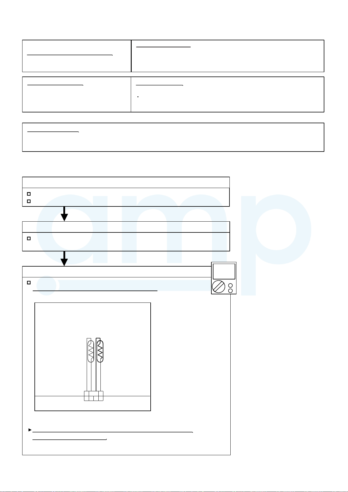
1-1-1 COOLING CAPACITY CONTROL
A sensor (room temperature thermistor) built in the indoor unit will usually perceive
difference or variation between a set temperature and present room temperature, and
controls the operation frequency of the compressor.
* If the room temperature is 6.0°C higher than a set temperature,
the compressor operation frequency will attain to maximum performance.
* If the
room temperature is 1.0°C lower than a set temperature, the compressor
will be stopped.
* When the room temperature is between +6.0°C to -1.0°C of the setting temperature,
the compressor frequency is controlled within the range shown in Table1.
However, the maximum frequency is limited in the range shown in Fig.1 based on the
fan speed mode and the outdoor temperature.
( Table 1 : Compressor Frequency Range )
minimum
frequency
10rps 120rps
maximum
frequency
( Fig. 1 : Limit of Maximum Frequency based on Outdoor Temperature )
Outdoor air
temperature
34°C
30°C
19°C
10°C
0°C
A zone
B zone
C zone
D zone
E zone
F zone
When the room
temperature rises
36°C
32°C
21°C
12°C
2°C
Fan speed mode
Model 18
Model 24
A zone
B zone
C zone
D-F zone
A zone
B zone
C zone
D-F zone
Hi Me Lo Qu
102rps
102rps
60rps
51rps
111rps
111rps
80rps
62rps
55rps
55rps
49rps 43rps
43rps 37rps
67rps
67rps
56rps 47rps
47rps 40rps
49rps
49rps
56rps
56rps
34rps
34rps
34rps
25rps
34rps
34rps
34rps
25rps
When the room
temperature drops
01-01
Page 5

1-2. HEATING OPERATION
AMP Air Conditioning
www.ampair.co.uk | sales@ampair.co.uk
A sensor (room temperature thermistor) built in the indoor unit will usually perceive
difference or variation between a set temperature and present room temperature, and
controls the operation frequency of the compressor.
* If the room temperature is lower 6.0°C than a set temperature,
the compressor operation frequency will attain to maximum performance.
* If the room temperature is higher 1.0°C than a set temperature, the compressor
will be stopped.
* When the room temperature is between +1.0°C to -6.0°C of the setting temperature,
the compressor frequency is controlled within the range shown in Table2.
( Table 2 : Compressor Frequency Range )
minimum
frequency
maximum
frequency
12rps
120rps
01-02
Page 6

1-3. DRY OPERATION
AMP Air Conditioning
www.ampair.co.uk | sales@ampair.co.uk
1-3-1 INDOOR UNIT CONTROL
The compressor rotation frequency shall change according to set temperature and room
temperature variation which the room temperature sensor of the indoor unit has detected
as shown in the Table 3.
( Table 3 : Compressor frequency )
Operating frequency
X zone
J zone
34rps
0rpsY zone
( Fig.2 : Compressor Control based on Room Temperature )
Room Room
temperature temperature
Ts+1.5°C
X zone
Ts+0.5°C
J zone
Ts-1.5°C
Y zone
( Fig.3 : Indoor Fan Control )
Ts-0.5°C
Ts : Setting temperature
Compressor
ON
OFF
Setting air flow
Lo
S-Lo
OFF
10 30 60 360 120 360 120 10 30 (sec)
01-03
Page 7

1-4. AUTO CHANGEOVER OPERATION
AMP Air Conditioning
www.ampair.co.uk | sales@ampair.co.uk
When the air conditioner is set to the Auto mode by remote controller, operation starts in the optimum
mode from among the Heating, Cooling, and Monitoring mode. During operation, the
optimum mode is automatically switched in accordance with temperature changes. The temperature
can be set between 18°C and 30°C in 0.5°C (wireless and 2WIRE remote controller)
Or 1.0°C (3WIRE remote controller) steps.
When operation starts, indoor fan and outdoor fan are operated for around 1 minutes.
1
Room temperature and outdoor temperature are sensed, and the operation mode is selected
in accordance with the table below. <Monitoring mode>
( Table 4 : Operation mode selection table )
Room temperature (TR)
Operation mode
TR : Room temperature
Ts : Setting temperature
TR> Ts+2°C
Ts+2°C TR Ts -2°C
TR < Ts -2°C Heating
Cooling
*Middle zone
*If it's Middle zone, operation mode of indoor unit is selected as below.
(1). Same operation mode is selected as outdoor unit.
If outdoor unit is operating in Cooling and Heating mode,
indoor unit will be operated by the same operation mode.
(2). Selected by the outdoor temperature.
If outdoor unit is operating in other than Cooling and Heating mode, indoor unit will be operated
according to the outdoor temperature as below.
( Fig.4 : Outdoor temperature zone selection )
Temperature
25
°C and over
25°C under
2
When the compressor was stopped for 6 consecutive minutes by the temperature control function
after the Cooling or Heating mode was selected at above, operation is switched
to Monitoring and the operation mode is selected again.
Mode
Cooling
Heating
1
3
When the middle zone is selected on the predetermining of the operation mode, the operation mode
before the changing to the monitor mode is selected.
01-04
Page 8

AUTO CHANGEOVER operation flow chart
AMP Air Conditioning
www.ampair.co.uk | sales@ampair.co.uk
START
Monitor mode
TS : Setting temperature
Room temp.
Ts+2
°C?
NO
Room temp.
°C?
Ts -2
NO
Middle zone
Auto change over is
second or more?
NO
YES
YES
NO
Operation mode
before the monitor mode is
cooling mode?
YES
YES
Thermostat remains
in OFF state for 6 minutes or
longer?
NO
YES
System stops
or operation command other than
auto changeover operation?
NO
Operation mode of
outdoor unit : Cooling?
YES
Operation mode of outdoor unit
YES
: Heating?
Outdoor temperature<
25°C?
01-05
NO
NO
NO
YES
COOLING OPERATIONHEATING OPERATION
Thermostat remains
in OFF state for 6 minutes or
longer?
NO
System stops
or operation command other than
auto changeover operation?
NO
YES
YES
Page 9

1-5. INDOOR FAN CONTROL
AMP Air Conditioning
www.ampair.co.uk | sales@ampair.co.uk
1. Fan speed
( Table 5 : Standard of Indoor Fan Speed )
*The following fan speed is a standard value.
(Static pressure 35Pa)
Operation
mode
Heating
Cooling
/ FAN
FAN
S-Lo
Dry
Air flow
mode
HIGH
MED
LOW
Quiet
HIGH
MED
LOW
Quiet
Soft Quiet
Speed (rpm)
Model 18
820
660
590
520
820
660
590
520
480
350
520
Model 24
1130
930
780
680
1130
930
780
680
560
420
680
2. FAN OPERATION
The airflow can be switched in 4 steps such as AUTO, QUIET, LOW, MED, HIGH, while the indoor
fan only runs.
When [AUTO] is selected, the indoor fan motor runs MED.
3. COOLING OPERATION
Switch the airflow [AUTO], and the indoor fan motor will run according to a room temperature,
as shown in Fig.5.
On the other hand, if switched in [HIGH] ~ [LOW], the indoor motor will run at a constant airflow of [COOL]
operation modes LOW, MED, HIGH,as shown in Table 5.
( Fig.5 : Airflow change - over ( Cooling : AUTO ) )
*1
When the room
temperature rises
TR : Room temperature
Ts : Setting temperature
TR-Ts > 2°C
=
2°C > TR-Ts > 1°C
=
1°C > TR-Ts
HIGH mode
MED mode
LOW mode
When the room
temperature drops
TR-Ts > 2.5°C
=
2.5°C > TR-Ts > 1.5°C
1.5°C > TR-Ts
*1 : Contains a condition to the following
When the operation mode is set to AUTO mode
at the start of operation.
When the setting temperature was changed.
When the operation mode was changed to COOLING mode.
When the airflow mode was changed to AUTO mode.
=
01-06
Page 10

4. HEATING OPERATION
AMP Air Conditioning
www.ampair.co.uk | sales@ampair.co.uk
Switch the airflow [AUTO], and the indoor fan motor will run according to a room temperature,
as shown in Fig.6.
On the other hand, if switched in [HIGH] ~ [LOW], the indoor motor will run at a constant airflow
of [HEAT] operation modes LOW, MED, HIGH, as shown in Table5.
( Fig.6 : Airflow change - over ( Heating : AUTO ) )
Indoor heat exchanger
temperature
TR-Ts > -1.0°C
=
1.0°C > TR-Ts > -2.0°C
=
-2.0°C > TR-Ts
LOW mode
MED mode
TR-Ts > -1.5°C
=
-1.5°C > TR-Ts > -2.5°C
=
HIGH mode
-2.5°C > TR-Ts
5. COOL AIR PREVENTION CONTROL (Heating mode)
The maximum value of the indoor fan speed is set as shown in Fig.7, based on the detected
temperature by the indoor heat exchanger sensor on heating mode.
When the compressor does not operate, the indoor fan motor operates [S-Lo] mode.
( Fig.7 : Cool Air Prevention Control )
I Indoor heat exchanger
t temperature
SETTING
FAN MODE
37°C
ndoor heat exchanger
emperature
27°C
SETTING
FAN MODE
Lo mode*
29°C
13 min. later
24°C
S-Lo
6. DRY OPERATION
Refer to the table 5.
During the dry mode operation, the fan speed setting can not be changed.
Lo mode*
Lo mode*
*On the Quiet mode, the Quiet mode is kept*On the Quiet mode, the Quiet mode is kept. .
01-07
Page 11

7. FAN CONTROL FOR ENERGY SAVING
AMP Air Conditioning
www.ampair.co.uk | sales@ampair.co.uk
When the air flow setting except AUTO mode, the indoor fan motor will run as shown in Fig.8.
( Fig 8 : Indoor Fan Control)
ON
Compressor
OFF
Indoor fan
Setting air flow
480rpm
S-Lo
OFF
10 30 60 180 60 180 60 10 30
( Factory setting)
Setting Description Function Number Setting Value
Disable
Enable
Remote controller
49
00
01
02
00 : When the outdoor unit is stopped, the indoor unit fan operates continuously following
the setting on the remote controller.
01 : When the outdoor unit is stopped, the indoor unit fan operates intermittently at a very
low speed.
02 : Enable or disable this function by remote controller setting.
Set to “00”or “01”when connecting a remote controller that cannot set
the Fan control for energy saving function or connecting a network converter.
To confirm if the remote controller has this setting,
refer to the operating manual of each remote controller.
(sec)
01-08
Page 12

1-6. OUTDOOR FAN CONTROL
AMP Air Conditioning
www.ampair.co.uk | sales@ampair.co.uk
1. Outdoor Fan Motor
F
ollow
ing table shows the fan speed of the outdoor unit.
( Table 6
: Fan speed of the outdoor unit )
Cooling
Heating
Normal Normal
S-Hi2
S-Hi1
Hi3
Hi2
Hi1
Me2
Me1
Lo2
Lo1
Zone control (rps:Compressor frequency)
1) Cool / Heat (Normal)
72rps
43rps
37rps
27rps
15rps
-
1100
1100 1100
1100
1100
870
870
720
500
500
1050
1050
780
720
590
590
480
Hi2
Hi1
Me2
Me1
Lo2
Lo1
Dry
Normal
-
-
-
-
530
-
530
-
530
Low ambient cooling / Dry
F zone G zone
-
-
-
-
430
350
-
370
300
-
300
68rps
40rps
35rps
24rps
15rps
260
H zone
-
-
-
-
-
-
-
-
250
-
-
250
-
-
200
2) Dry (Nomal)
19rps and over [ Hi 1 ]
16rps and over [ Me 1 ]
16rps under [ Lo 1 ]
Ambient Temperature zone
D zone(Normal 1)
21°C
D zone(Normal 2)
12°C
F zone
2°C
G zone
-8°C
H zone
19°C
10°C
0°C
-10°C
3) Cool / Dry / F zone
51rps and over [ Hi 1 ]
43rps and over [ Me 1 ]
43rps under [ Lo 1 ]
4) Cool / Dry / G zone
51rps and over [ Hi 1 ]
43rps and over [ Me 1 ]
43rps under [ Lo 1 ]
5) Cool / Dry / H zone
43rps and over [ Hi 1 ]
34rps and over [ Me 1 ]
34rps under [ Lo 1 ]
01-09
Page 13

1-7. COMPRESSOR CONTROL
AMP Air Conditioning
www.ampair.co.uk | sales@ampair.co.uk
1. OPERATION FREQUENCY RANGE
The operation frequency of the compressor is different based on the operation mode as
shown in Table 7.
(Table 7 : Compressor Operation Frequency Range)
Cooling / Dry Heating
Min
Max Min Max
12rps10rps 120rps
120rps
2. OPERATION FREQUENCY CONTROL AT START UP
The compressor frequency soon after the start-up is controlled as shown in Fig.9.
(Fig.9 : Compressor Control at Start-up)
Normal start-up
Frequency
Frequency
Frequency
Frequency
Frequency
Time 1
Time 2 Time 3
Time 4
Time 5
(Frequency)
Frequency Frequency Frequency
35rps 53rps 66rps 82rps 106rps
Frequency
(Time)
Time 1
80sec 160sec 300sec 440sec 500sec
Time 2 Time 3 Time 4 Time 5
Frequency
01-10
Page 14

1-8. TIMER OPERATION CONTROL
AMP Air Conditioning
www.ampair.co.uk | sales@ampair.co.uk
1-8-1 Wired Remote Controller
UTY-RNR*Z1(2 wire remote controller)
ON / TIMER
OFF / TIMER
WEEKLY TIMER
*3 wire remote controller can be connected
If 3 wire remote controller is connected, set the DIP-SW on the controller PCB
Refer to the installation manual for detailed.
If used in combination with wireless and wired remote controller, the following function is limited.
Sleep timer
Timer
10°C heat operation
1. ON / OFF TIMER
OFF timer : When the clock reaches the set time, the air conditioner will be turned off.
Operation mode
Stop mode
Set time of timer
ON timer : When the clock reaches the set time, the air conditioner will be turned on.
Operation mode
Stop mode
Set time of timer
2. WEEKLY TIMER
2-1. WEEKLY TIMER
Use this timer function to set operating time for each day of the week.
The weekly timer allows up to two ON and OFF time to set up per day.
Operation mode
Stop mode
Operation mode
Stop mode
Operation mode
Stop mode
Set time
The operating time can be set in 30 min increments only.
The OFF time can be carried over to next day.
The ON timer and the OFF timer functions cannot be set with using the weekly timer.
Both ON and OFF time must be set.
Set time Set time Set time
01-11
Page 15

2-2. DAY OFF setting
AMP Air Conditioning
www.ampair.co.uk | sales@ampair.co.uk
The DAY OFF setting is only available for days for which weekly settings already exist.
If the operating time carries over to the next day (during a next day setting), the effective
DAY OFF range will be set as shown below.
Normal
DAY OFF
Operation mode
Operation mode
Stop mode
Stop mode
Preceding day Next day
Setting day
Stop mode
Next day setting
DAY OFF
Operation mode
Stop mode
Stop mode
Operation mode
Stop mode
Preceding day Next daySetting day
The DAY OFF setting can only be set one time. The DAY OFF setting is cancelled automatically
after the set day has passed.
01-12
Page 16

1-8-2 Wireless Remote Controller (OPTION)
AMP Air Conditioning
www.ampair.co.uk | sales@ampair.co.uk
AR- REJ1E
ON / TIMER
OFF / TIMER
PROGRAM TIMER
SLEEP TIMER
1. ON / OFF TIMER
OFF timer : When the clock reaches the set time, the air conditioner will be turned off.
Operation mode
Stop mode
Set time of timer
ON timer : When the clock reaches the set time, the air conditioner will be turned on.
Operation mode
Stop mode
Set time of timer
2. PROGRAM TIMER
The program timer allows the OFF timer and ON timer to be used in combination one time.
Operation mode
Stop mode
Set time
Operation will start from the timer setting (either OFF timer or ON timer)
whichever is closest to the clock's current timer setting.
The order of operations is indicated by the arrow in the remote control unit's display.
SLEEP timer operation cannot be combined with ON timer operation.
Operation mode
Stop mode
Set time Set time Set time
Operation mode
Stop mode
01-13
Page 17

3. SLEEP TIMER
AMP Air Conditioning
www.ampair.co.uk | sales@ampair.co.uk
If the sleep timer is set, the room temperature is monitored and the operation is stopped automatically.
If the operation mode or the set temperature is change after the sleep timer is set, the operation is
continued according to the changed setting of the sleep timer from that time ON.
In the COOLING operation mode
When the sleep timer is set, the setting temperature is increased 1 degC.
It increases the setting temperature another 1 degC after 1 hour.
After that, the setting temperature is not changed and the operation is stopped at the time
of timer setting.
Set temperature rises
( Ts : Set temperature )
Stop of operation
+2°C
+1°C
Ts
Set
60min
In the HEATING operation mode
When the sleep timer is set, the setting temperature is decreased 1 degC.
It decreases the setting temperature another 1 degC every 30 minutes.
Upon lowering 4 degC, the setting temperature is not changed and the operation stops
at the time of timer setting.
Set temperature lowers
( Ts : Set temperature )
Ts
-1°C
-2°C
-3°C
-4°C
Stop of operation
Set
30min
60min
90min
01-14
Page 18

1-9. ELECTRONIC EXPANSION VALVE CONTROL
AMP Air Conditioning
www.ampair.co.uk | sales@ampair.co.uk
The most proper opening of the electronic expansion valve is calculated and controlled under the
present operating condition based on the following values.
The compressor frequency, the temperatures detected by the discharge temperature sensor
and the outdoor temperature sensor.
The pulse range of the electronic expansion valve control is 52 ~ 480 pulses (Cooling) and 52 ~ 480
pulses (Heating).
At the time of supplying the power to the outdoor unit, the initialization of the electroni
expansion valve is operated (528 pulses are input to the closing direction).
1-10. TEST OPERATION CONTROL
With Wired Remote Controller
Touch the [Test run] in the “Maintenance” screen.
(Installer password* is required.)
The “Test Run” screen is displayed.
Touch [OK] to return to the Maintenance screen, and start the test run.
The test run will automatically end is approximately 60 min.
If you wish to cancel the test run before it is complete, return to the “Monitor Mode screen”, and touch
the On/Off button.
*If the password has been changed from the default setting “0000”,
please contact the installer.
c
With Wireless Remote Controller
Under the condition where the air conditioner runs, press the TEST RUN button, and
the test operation control mode will appear.
During test running, the Operation LED and Timer LED of the air conditioner body blinks simultaneously.
Set the test operation mode, and the compressor will continue to run regardless of whether the room
temperature sensor detects.
The test operation mode is released if 60 minutes have passed after setting up the test operation.
1-11. PREVENT TO RESTART FOR 3 MINUTES ( 3 MINUTES ST )
The compressor won't enter operation status for 3 minutes after the compressor is stopped,
even if any operation is given.
1-12. 4-WAY VALVE EXTENSION SELECT
At the time when the air conditioner is switched from the cooling mode to heating mode,
the compressor is stopped, and the 4-way valve is switched in 3 minutes later
after the compressor stopped.
01-15
Page 19

1-13. AUTO RESTART
AMP Air Conditioning
www.ampair.co.uk | sales@ampair.co.uk
When the power was interrupted by a power failure, etc. during operation, the operation contents
at that time are memorized and when power is recovered, operation is automatically resumed with
the memorized operation contents.
When the power is interrupted and recovered during timer operation, timer operation is canceled,
but only setting time is memorized.
[Operation contents memorized when the power is interrupted]
Operation mode
Set temperature
Set air flow
Timer mode and timer time (Set by wireless remote controller)
10°C HEAT (Wireless remote controller is in use)
ECONOMY
Energy saving setting
Each central setting
1-14. PUMP DOWN
01-16
Page 20

1-15. COMPRESSOR PREHEATING
AMP Air Conditioning
www.ampair.co.uk | sales@ampair.co.uk
When the outdoor temperature is lower than 0°C and the all operation mode has been
stopped for 30 minutes, power is applied to the compressor and the compressor is heated.
(By heating the compressor, warm air is quickly discharged when operation is started.)
When operation was started and when the outdoor temperature rises to 25°C or greater,
preheating is ended.
1-16. 10°C HEAT OPERATION
The 10°C HEAT operation
The 10°C HEAT
The 10°C HEAT
( Table9 )
Mode Heating
Setting temperature 10°C
Fan mode AUTO
operation can be set by the wireless remote controller.
operation is almost the same operation as below settings.
functions by pressing 10°C.HEAT button on the remote controller.
1-17. ECONOMY OPERATION
The ECONOMY operation functions by pressing ECONOMY button on the remote controller.
The ECONOMY operation is almost the same operation as below settings.
( Table10)
Mode Cooling/ Dry Heating
Target temperature Setting temp.+1°C Setting temp.-1°C
01-17
Page 21

1-18. DEFROST OPERATION CONTROL
AMP Air Conditioning
www.ampair.co.uk | sales@ampair.co.uk
1. CONDITION OF STARTING THE DEFROST OPERATION
The defrost operation starts when the outdoor heat exchanger temperature sensor (Tn) detects
the temperature lower than the values shown in Table11.
( Table 11 : Condition of starting Defrost Operation )
ST
1 time defrosting
after starting operation
Less than 22 min. 22 to 62 min. More than 62 min.
Compressor integrating operation time
Does not operate
Defrosting after 2 time
ND
upon starting operation
Tn10 : Temperature of continuous operation at 10minutes.
Tnb : Back 5minutes temperature
Integrating defrost
(Constant monitoring)
*1 : If the compressor continuous operation time is less than 10 minutes,
the OFF number of the compressor is counted.
If any defrost operated, the compressor OFF count is cleared.
More than 240 min.
(For long continuous operation)
Compressor integrating operation time
Less than 35 min. More than 35min.
Does not operate
Compressor integrating operation time
- 3°C
- 9°C - 5°C
Tn-Tn10 < - 5deg
Tn-Tnb < - 2deg
However, Tn < - 6°C
OFF count of the compressor
40 times.
=
Less than 10min.*1
(For intermittent operation)
2. CONDITION OF THE DEFROST OPERATION COMPLETION
Defrost operation is released when the conditions become as shown in Table12.
( Table12 : Defrost Release Condition )
Release Condition
Outdoor heat exchanger temperature sensor value is higher than
+13°C or Compressor operation time has passed 15 minutes.
01-18
Page 22

3. Defrost Flow Chart
AMP Air Conditioning
www.ampair.co.uk | sales@ampair.co.uk
The defrosting shall proceed by the integrating operation time, outdoor temperature
and outdoor heat exchanger temperature as follows.
Heating operation start : Compressor ON
(Not defrosted for 10 minutes)
1st defrost
Compressor
integrating
operation:
Over 22 min.
Outdoor
heat exchanger
temperature:
Below - 9°C
Compressor
integrating
operation:
Over 62 min.
Outdoor
heat exchanger
temperature:
Below - 5°C
2nd and later defrost Integrating defrost
(Constant monitoring)
Compressor
integrating
operation:
Over 35 min.
Tn-Tn10 < - 5deg
Tn-Tnb < - 2deg
However, Tn <- 6°C
=
Defrost start
Compressor
OFF count :
40 times
(Less than 10min.)
Compressor
integrating
operation:
Over 240 min.
Outdoor
heat exchanger
temperature:
Below - 3°C
Defrost Indicator:
[Operation lamp]
6 sec ON / 2 sec OFF
Compressor OFF
Outdoor fan motor OFF
30 sec later four - way valve OFF
35 sec later compressor ON
Outdoor heat exchanger temperature:
Over +13°C
or
Compressor ON time: Maximum 15 minutes
Defrost end
01-19
Page 23

1-19. OFF DEFROST OPEARTION CONTROL
AMP Air Conditioning
www.ampair.co.uk | sales@ampair.co.uk
When operation stops in the [Heating operation] mode, if frost is adhered to the outdoor unit heat
exchanger, the defrost operation will proceed automatically. In this time, if indoor unit operation
lamp flashes slowly (7 sec ON / 2 sec OFF), the outdoor unit will allow the heat exchanger to defrost,
and then stop.
1. OFF DEFROST OPERATION CONDITION
In heating operation, the outdoor heat exchanger temperature is less than -4°C,
compressor continuous operation more than 10 minutes, and
compressor operation integrating time lasts for more than 30 minutes.
2. OFF DEFROST END CONDITION
Release Condition
Outdoor heat exchanger temperature sensor value is higher than +13°C
or Compressor operation time has passed 15 minutes.
OFF Defrost Flow Chart
Heating operation stop
Outdoor heat exchanger temperature :
Below -4°C
Compressor continuous operation :
Over 10 minutes
Compressor integrating operation :
Over 30 minutes
Defrost start
Defrost Indicater:
[Operation lamp]
6 sec ON / 2 sec OFF
Outdoor heat exchanger temperature :
Over +13°C
or
Compressor ON time : Maximum 15 minutes
Defrost end
01-20
Page 24

1-20. VARIOUS PROTECTIONS
AMP Air Conditioning
www.ampair.co.uk | sales@ampair.co.uk
1. DISCHARGE GAS TEMPERATURE OVERRISE PREVENTION CONTROL
The discharge gas thermosensor (discharge thermistor : Outdoor side) will detect discharge gas
temperature.
When the discharge temperature becomes higher than Temperature ,the compressor frequency
is decreased 20rps, and it continues to decrease the frequency for 20rps every
the temperature becomes l
ower than Temperature .
When the discharge temperature becomes lower than Temperature , the control of
the compressor frequency is released.
When the discharge temperature becomes higher than Temperature ,the compressor is stopped
and the indoor unit LED starts blinking.
(Table14 : Discharge Temperature Over Rise Prevention Control / Release Temperature)
120 seconds until
Temperature
Temperature
Temperature
104°C 101°C 110°C
2. CURRENT RELEASE CONTROL
The compressor frequency is controlled so that the outdoor unit input current does not exceeds
the current limit value that was set up with the outdoor temperature.
The compressor frequency returns to the designated frequency of the indoor unit at the time
when the frequency becomes lower than the release value.
( Table 15 : Current release operation value / release value )
Model 18
[ Heating ]
OT (Control / Release)
7.0A / 6.5A
17°C
9.0A / 8.5A
12°C
10.5A / 10.0A
5 °C
12.0A / 11.5A
[ Cooling ]
OT (Control / Release)
50°C
46°C
40°C
4.5A / 4.0A
4.5A / 4.0A
6.0A / 5.5A
8.5A / 8.0A
OT : Outdoor Temperature
Model 24
[ Heating ]
OT (Control / Release)
10.5A / 10.0A
17°C
13.0A / 12.5A
12°C
15.0A / 14.5A
5 °C
17.0A / 16.5A
OT : Outdoor Temperature
OT : Outdoor Temperature
[ Cooling ]
OT (Control / Release)
50°C
46°C
40°C
OT : Outdoor Temperature
7.0A / 6.5A
7.0A / 6.5A
9.5A / 9.0A
12.0A / 11.5A
01-21
Page 25

3. ANTIFREEZING CONTROL (Cooling and Dry mode)
AMP Air Conditioning
www.ampair.co.uk | sales@ampair.co.uk
The compressor frequency is decrease on cooling & dry mode when the indoor heat exchanger
temperature sensor detects the temperature lower than Temperature .
Then, the anti-freezing control is released when it becomes higher than Temperature .
(Table 16 : Anti-freezing Protection Operation / Release Temperature)
Outdoor temperature
Over than 10°C
or 12°C *2
Less than 10°C *1
or 12°C *2
*1. When the temperature rises.
*2. When the temperature drops.
Temperature Temperature
*1
4°C
7°C
13°C
4. COOLING PRESSURE OVERRISE PROTECTION
When the outdoor unit heat exchange sensor temperature rises to 67°C or greater,
the compressor is stopped and trouble display is performed.
5. INDOOR UNIT FAN MOTOR OVER TEMPERATURE PROTECTION
When satisfy the following conditions, the protection works.
a) After the 90 seconds from the fan operation, detect less than 300 rpm for 10 seconds.
b) IPM trip protection works.
c) Current overload protection works.
When detecting the above condtion, recheck the condition after 6 minutes.
When count the twice, the protection works
Protection contents
Reduce the static pressure 20 Pa
When it does not dissolve even the minimum static pressure condition, work the following operation
a) Fan motor error displayed
b) Fan stop 40 secounds
c) Fan stop 50 secounds
01-22
Page 26

1-21. AUTOMATIC AIRFLOW ADJUSTMENT FUNCTION
AMP Air Conditioning
www.ampair.co.uk | sales@ampair.co.uk
The unit automatically sets the static pressure.
This setting can be used by the function setting 26.
The static pressure is calculated by the input current and voltage of the motor and
the return air temperature.
*For the setting method, refer to the technical manual.
NOTE
Be sure to conduct this setting before any other operation. If the motor is warm or the heat exchanger
is wet, false and detection may lead to incorrect adjustments.
Check if the electrical wirings and duct installations are complete.
If there is a damper installed in the system, make sure the damper is open.
Check if the air filter(optional) is attached.
If there are several inlet, outlet ports, make sure the airflow rates of each port match the
designed airflow rate by adjusting the throttles.
Automatic airflow adjustment is possible by the following procedures.
1) Change Function 26 to "Automatic airflo
2) Run the air conditioner on Fan mode (High).
* For instructions on how to operate the air conditioner, refer to the operation manual of the remote
controller.
Automatic During airflow ajustment, the mode will be fixed at Fan mode(High).
When this function is active, do not operate the Outdoor unit.
When the setting is performing, Test mode display: 3-Wire RC/ Maintenance dispaly: 2-Wire RC will be
shown on the remote controller panelle.
w adjustment (32)".
3) The air conditioner will run for about 1 to 8 min. then stop automatically.
* Do not change the throttles of the inlet and outlet ports during operation.
When used in a Group control system, the setting will take about 10 min.
When the Error code 15.4 (Automatic Air flo
Refer to the Trouble shooting Error code15
4) Turn the air conditioner off and on again.
5) Check the setting value of Function 26 and take note of the setting value.
* If the setting value has not changed, repeat the procedure from step 2.
w Adjustment Error) appears, the setting is not completed.
01-23
Page 27

1-22. DRAIN PUMP OPERATION
AMP Air Conditioning
www.ampair.co.uk | sales@ampair.co.uk
.
During Cooling / Dry mode
1. When the compressor starts, the drain pump starts simultaneously.
2. The drain pump operates continuously for 3 minutes after the compressor is turned off as show in Fig15.
3. When the compressor stops by the "Anti- freezing protection", the drain pump is turned off
in 1 hour after the compressor stops.
4. When the water level in the drain pan rises up and then the float switch functions:
1
The compressor, indoor and outdoor fan motor operation are stopped.
2
Drain pump operates continuously for 3 minutes after the float switch is turned off.
(Almost condensing water may be drained)
3
The indoor unit fan motor operates after the float switch is turned off.
5. When the float switch turns ON continuously for 3 minutes, "FAILURE INDICATION" operates.
(It is necessary to turn off power for release it. )
6. When the float switch turns OFF less than 3 minutes, the unit starts Cooling operation.
(Fig 15 : Detail of Drain Pump Operation)
3 minutes3 minutes
10 minutes 60 minutes
180 minutes
Drain Pump
ON
OFF
Start
(0 minutes)
<Float Switch turns OFF less than 3 minutes>
Less than 3 minutes
Float Switch
Compressor
Indoor Fan
Drain Pump
.
During Heating / Fan mode / Stop operation
ON
OFF
ON
OFF
3 minutes ST
ON
OFF
ON
OFF
3 minutes
1.When the water level in the drain pan rises up and then the float switch functions:
Drain pump operates continuously for 3 minutes after the float switch is turned off.
1
(Almost condensing water may be drained)
2. When the float switch turns ON continuously for 3 minutes, "FAILURE INDICATION" operates.
Thereafter, even if the float switch turns OFF, the "FAILURE INDICATION" is not released.
(It is necessary to turn off power for release it. )
3 minutes3 minutes
Float Switch
Drain Pump
ON
OFF
ON
OFF
3 minutes
01-24
Page 28

DUCT type
AMP Air Conditioning
www.ampair.co.uk | sales@ampair.co.uk
R410A
INVERTER
2 . TROUBLE SHOOTING
Page 29
2 ERROR DISPLAY
AMP Air Conditioning
www.ampair.co.uk | sales@ampair.co.uk
2-1 WIRED REMOTE CONTROLLER DISPLAY
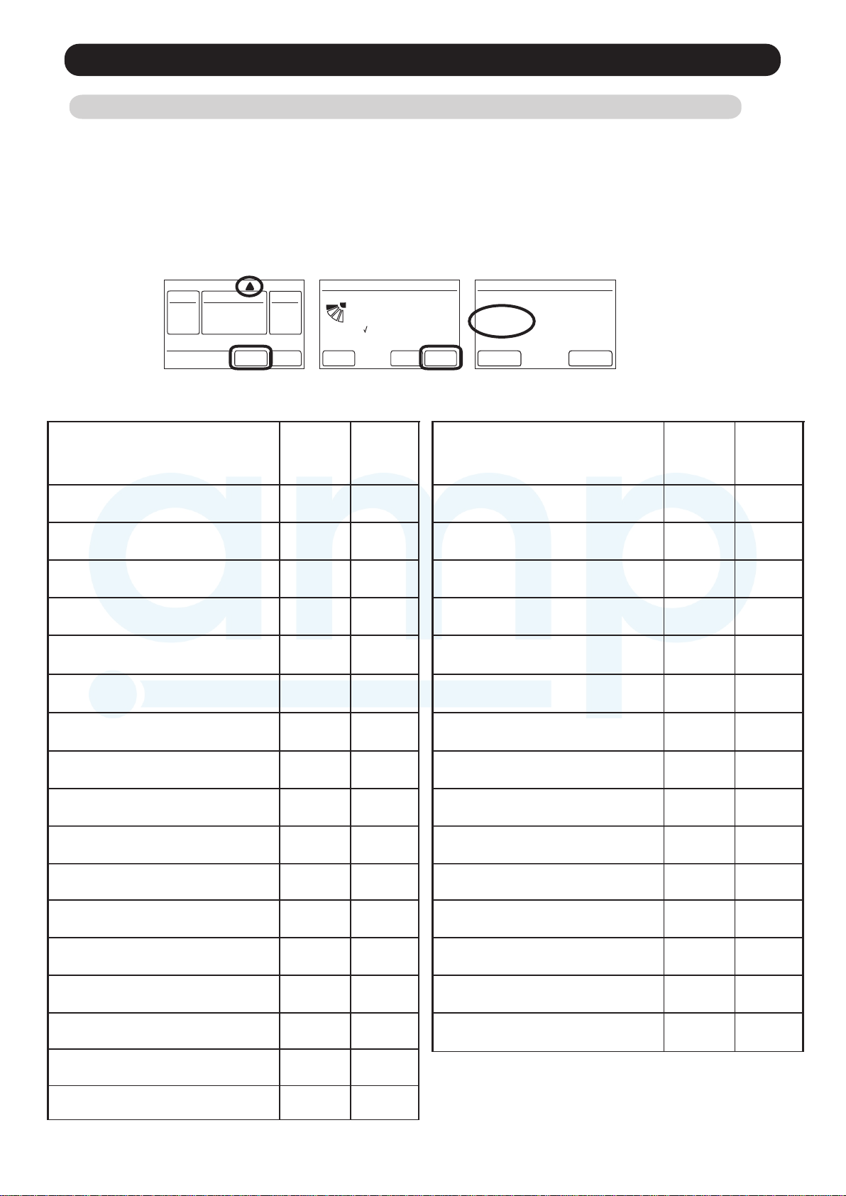
1. Check the error
1. If an error occurs, an error icon appears on the “Monitor mode screen”.
Touch the [Status] on the “Monitor mode screen”.The “Status” screen is displayed.
2. Touch the [Error Information] on the “Status”screen. The “Error Information”screen is displayed.
(If there are no errors, the [Error Information] will not be displayed.)
3. 2-digit numbers correspond to the error code in the table below. Touch the [Next page]
(or [Previous page]) to switch to other connected indoor units.
1. 2. 3.
Mode Set Temp.
!
Status
Fri 10:00AM
Fan
Menu
Status
Air Flow Direction
VT
[ 1 ]
Individual
[ ]
Economy
[ Off ]
Monitor Back
For the details of the indoor unit or outdoor unit error , refer to the error codes in each installation manual
Next
Page
Page 1/ 4
Error
Information
Error Information
Address
[ 02 01 ]
Error Code
[ 14 . 15, 41 . 44 ]
Page 1/ 5
Next
Page
Error Contents
Serial Communication Error
Wired Remote Controller
Communication Error
Automatic Air flow Adjustment Error
External communication Error
Combination Error
Indoor unit address setting Error
Connection unit number Error
(Indoor unit Wired remote controller Error)
Indoor unit PCB model
information Error
Indoor unit motor electricity
consumption detection Error
Indoor unit power supply Error for
fan motor
Indoor unit Communication circuit
(wired remote controller) Error
Error
Code
11
12
15
18
23
26
29
33
39
3A
Trouble
shooting
1,2
3
4
5
6
7
8
932
10
11
12
Error Contents
PFC circuit Error
Trip terminal L Error
Discharge Thermistor Error
Compressor Thermistor Error
Heat Ex. Liquid Outlet
Thermistor Error
Outdoor Thermistor Error
Heat Sink Thermistor Error
Current sensor Error
Pressure sensor Error
Trip detection
Compressor rotor position
detection Error
Error
Code
64
65
71
72
73
74
77
84
86
94
95
Trouble
shooting
19
20
21
22
23
24
25
26
27
28
29
Indoor Room Thermistor Error
Indoor Heat Ex. Thermistor Error
Indoor Unit Fan Motor Error
Drain pump Error
Outdoor unit main PCB model
information error
Inverter Error
41
42
51
53
62
63
13
14
15
16
17
18
Outdoor Unit Fan Motor Error
4-way Valve Error
Discharge Temp. Error
Compressor Temp. Error
02-01
97
99
A1
A3
30
31
32
33
Page 30
2-2 TROUBLE SHOOTING WITH ERROR CODE
AMP Air Conditioning
www.ampair.co.uk | sales@ampair.co.uk
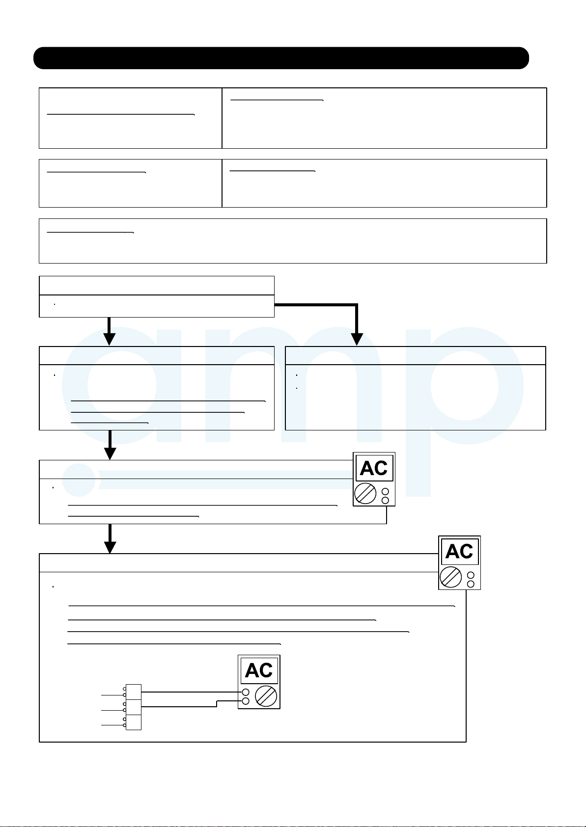
Trouble shooting 1
Indicate or Display:
OUTDOOR UNIT Error Method:
Serial communication error
Error code : 11
(Serial Reverse Transfer Error)
Detective Actuators:
Outdoor unit Main PCB
Outdoor unit fan motor
Detective details:
When the indoor unit cannot receive the serial signal from Outdoor unit
more than 2minutes after power ON, or the indoor unit cannot receive
the serial signal more than 15seconds during normal operation.
Forecast of Cause:
1. Connection failure 2. External cause 3. Main PCB failure 4. Outdoor unit fan motor failure
Check Point 1-1 : Reset the power and operate
Does Error indication show again?
YESYES
Check Point 2 : Check Connection
Check any loose or removed connection line of
Indoor unit and Outdoor unit.
>> If there is an abnormal condition, correct it by
referring to Installation Manual or Data &
Technical Manual.
Outdoor unit : No indication
NO
Check Point 1-2: Check external cause such as noise
Check the complete insulation of the grounding.
Check if there is any equipment that causes harmonic wave
near the power cable (Neon light bulb or any electronic
equipment which causes harmonic wave).
OK
Check Point 3 : Check the voltage of power supply
Check the voltage of power supply
>> Check if AC198V (AC220V -10%) - 264V (AC240V +10%) appears
at Outdoor Unit Terminal L - N.
OK
Check Point 4 : Check Serial Signal (Reverse Transfer Signal)
Check Serial Signal (Reverse Transfer Signal)
>> Check if Indicated value swings between AC90V and AC270V at Outdoor Unit Terminal L - 3.
>> If it is abnormal, Check Outdoor unit fan motor (PARTS INFORMATION 5)
>> If Outdoor fan motor is abnormal, replace Outdoor unit fan motor and Main PCB.
>> If Outdoor fan motor is normal, replace Main PCB.
RED
BLACK
WHITE
3
L
N
+
-
02-02
Page 31

Trouble shooting 2
AMP Air Conditioning
www.ampair.co.uk | sales@ampair.co.uk
Indicate or Display:
INDOOR UNIT Error Method:
Serial Communication Error
Error code : 11
(Serial Forward Transfer Error)
Detective Actuators: Detective details:
Indoor unit Controller PCB
When the outdoor unit cannot properly receive the serial signal from
indoor unit for 10 seconds or more.
Forecast of Cause:
1. Connection failure 2. External cause 3. Controller PCB failure
Outdoor unit : No indication
Check Point 1-1 : Reset the power and operate
Does error indication reappear?
NO
YESYES
Check Point 2 : Check connection
Check any loose or removed connection line of
between indoor unit and outdoor unit.
>> If there is an abnormal condition, correct it by
referring to Installation Manual or Data &
Technical Manual.
Check connection condition in control unit.
(If there is loose connector, open cable or mis-wiring)
Check Point 1-2 : Check external cause such as noise
OK
Check Point 3 : Check the voltage of power supply
Check the voltage of power supply
>> Check if AC198V(AC220V-10%) - 268V(AC240V+10%) appears
at outdoor unit terminal L - N.
OK
Check if the ground connection is proper.
Check if there is any equipment that causes harmonic wave
near the power cable (Neon light bulb or any electronic
equipment which causes harmonic wave).
Check Point 4 : Check serial signal (Forward transfer signal)
Check serial signal (Forward transfer signal)
>> Check if indicated value swings berween AC30v and AC130V at outdoor unit terminal 2 - 3.
>> If it is abnormal, replace Controller PCB.
BLACK
WHITE
RED
BLACK
WHITE
1
2
3
L
N
+
-
02-03
Page 32

Trouble shooting 3
AMP Air Conditioning
www.ampair.co.uk | sales@ampair.co.uk
INDOOR UNIT Error Method:
Wired Remote Controller
Indicate or Display:
Error code : 12
Outdoor unit : No indication
Communication Error
Detective Actuators: Detective details:
Indoor unit Controller PCB
Wired Remote Controller
When the indoor unit cannot properly receive the signal from
Wired Remote Controller for 1 minute or more.
Forecast of Cause:
1. Connection failure 2. Wired Remote Controller failure 3. Controller PCB failure
Check Point 1 : Check the connection of terminal
After turning off the power,
Check & correct the followings.
Check the connection of terminal berween Wired Remote Controller and indoor unit,
and check if there is a disconnection of the cable.
OK
Check Point 1-2 : Check Wired Remote Controller and Controller PCB
Ceck Voltage at CN14 of Controller PCB. (Terminal 1-3, Terminal 1-2)
(Power supply for the Remote Control)
>> If it is DC13V, Remote Control is failure. (Controller PCB is normal) >> Replace Remote Control
>> If it is DC 0V, Controller PCB is failure. (Check Remote Control once again) >> Replace Controller PCB
Check Point 2 : Wire installation Wrong RCgroup setting
Wrong wire connection in RCgroup (Please refer to the installation manual)
The number of connecting indoor unit and Remote controller in one RCgroup were less than 32 units.
Check Point 2-1 : Check Indoor unit controller PCB
Check if controller PCB damage
Change controller PCB and check the Error after setting remote controller address
02-04
Page 33

Trouble shooting 4
AMP Air Conditioning
www.ampair.co.uk | sales@ampair.co.uk
INDOOR UNIT Error Method:
Automatic Air flow Adjustment Error
Indicate or Display:
Error code : 15
Outdoor unit : No indication
Detective Actuators:
Indoor unit controller PCB
Detective details:
On automatic airflow adjustment operation, when the fan speed other than
0rpm is detected at the 0rpm operation.
On automatic airflow adjustment operation, when the fan speed is not reach
the target speed, after 2 minutes from the fan started.
On automatic airflow adjustment operation operation, when the 750W
of input power is detected.
Forecast of Cause:
1. Fan rotation failure 2. Fan motor winding open 3. Indoor unit controller PCB
Check Point 1 : Check rotation of Fan
Rotate the fan by hand when operation is off.
(Check if fan is caught, dropped off or locked motor)
>>If Fan or Bearing is abnormal, replace it.
OK
Check Point 2 : Check ambient temp. around motor
Check excessively high temperature around the motor.
(If there is any surrounding equipment that causes heat)
>>Upon the temperature coming down, restart operation.
OK
Check Point 3 : Check Indoor unit fan motor
Checl Indoor unit fan motor. (PARTS INFORMATION 4)
>>if Indoor unit fan motor is abnormal, replace Indoor unit fan motor.
OK
Check Point 4 : Replace Controller PCB
If Check Point 1- 3 do not improve the symptom, replace Controller PCB.
02-05
Page 34

Trouble shooting 5
AMP Air Conditioning
www.ampair.co.uk | sales@ampair.co.uk
INDOOR UNIT Error Method:
External communication error
Indicate or Display:
Error code : 18
Outdoor unit : No indication
Detective Actuators:
External communication error
Detective details:
After receiving a signal from the external I/O PCB,
the same a signal has not been received for 15sec
Forecast of Cause :
1. Connection failure 2.External I/O PCB failure 3.Controller PCB failure
Check Point 1 : Check the connection
Check any loose or removed connection of between the controller PCB to the external I/OPCB
>>If there is an abnormal condition, correct it by refer to installation manual or
the technical manual.
Check the condition condtion on the external I/O PCB and the controller PCB
(If there is loose connector, open cable or mis-wiring)
OKOK
Check Point 2: Replace external I/O PCB
If Check Point 1 do not improve the symptom, change External I/O PCB.
OKOK
Check Point 3: Replace Controller PCB
If Check Point 2 do not improve the symptom, change Controller PCB.
02-06
Page 35
Trouble shooting 6
AMP Air Conditioning
www.ampair.co.uk | sales@ampair.co.uk
Indicate or Display:
INDOOR UNIT Error Method:
Combination error
Error code : 23
Detective Actuators: Detective details:
Indoor unit
1. The outdoor unit receives the serial signal of applied refrigerant information
from Indoor unit. When the refrigerant is R410a.
2. When the outdoor unit type is multi.
Forecast of Cause:
1. The selection of indoor units is incorrect
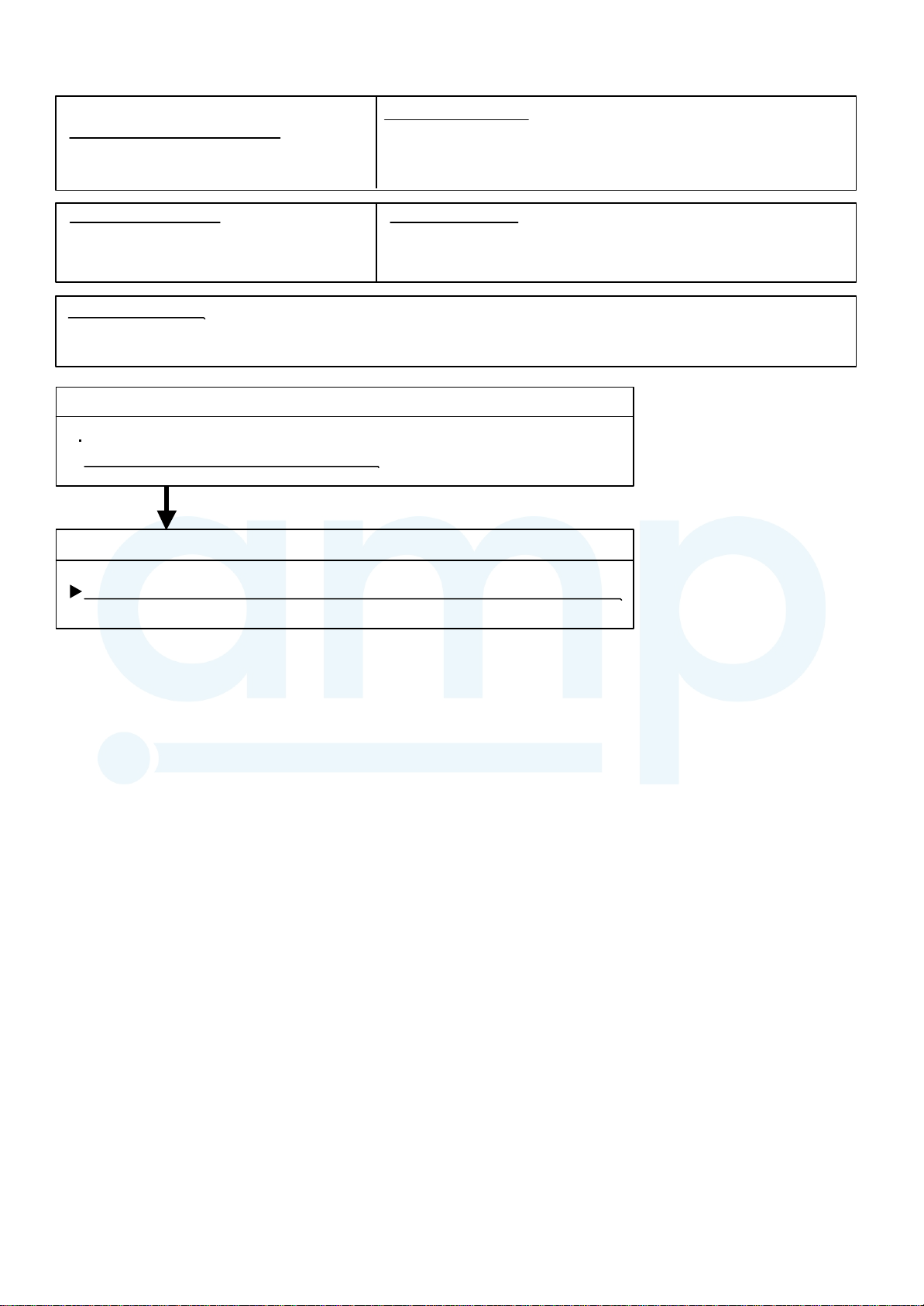
Check Point 1 : Check the type of indoor unit
Check the type of the connected indoor unit.
>> If abnormal condition is found, correct it.
OK
Check Point 2 : Replace Main PCB
Outdoor unit : No indication
If Check Point 1 do not improve the symptom, replace Main PCB of Outdoor unit.
02-07
Page 36

Trouble shooting 7
AMP Air Conditioning
www.ampair.co.uk | sales@ampair.co.uk
INDOOR UNIT Error Method:
Indoor unit address setting error
Indicate or Display:
Error code : 26
Outdoor unit : No indication
Detective Actuators:
Wired remote controller ( 2-Wire )
Indoor unit Controller PCB circuit
Forecast of Cause :
1. Wrong wiring of RCgroup 2. Wrong remote address setting 3. Indoor unit controller PCB failure
4. Remote controller failure
Detective details:
When the address number set by auto setting and manual setting are mixed in
one RC group.
When the duplicated address number exists in one RC group.
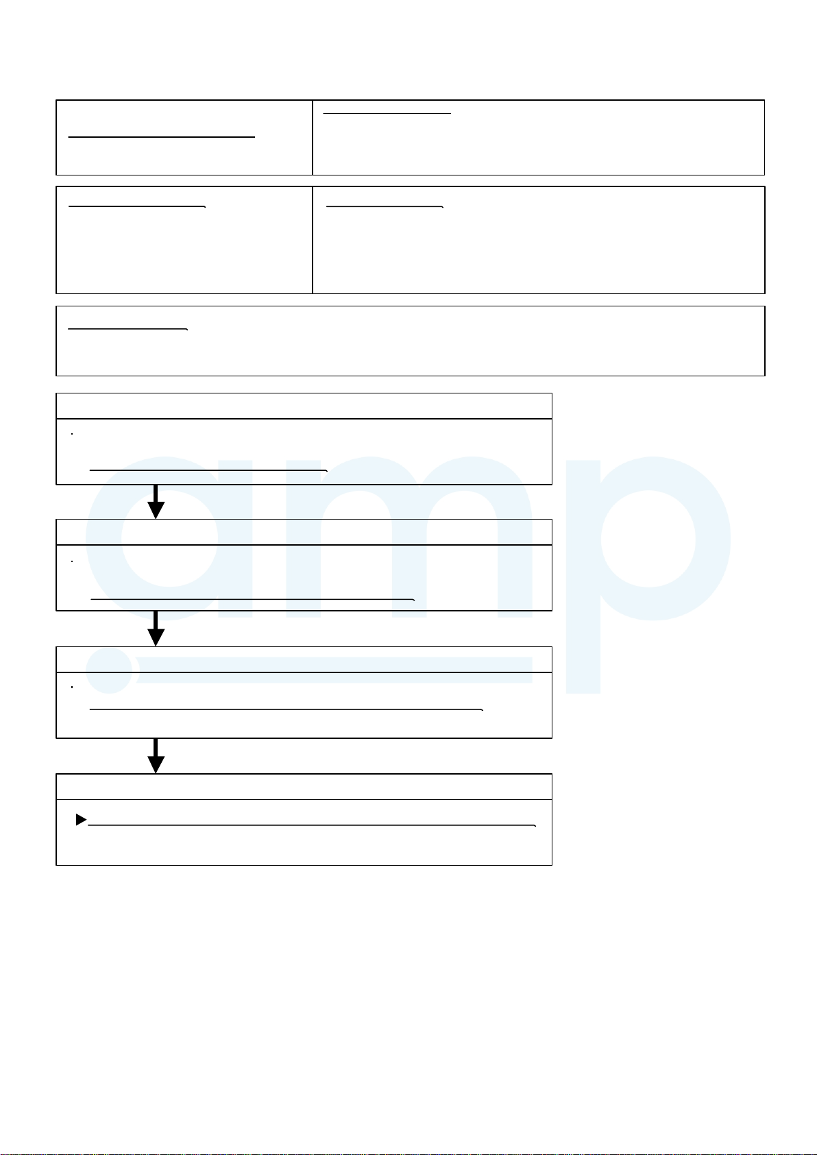
Check Point 1 : Wire installation
Wrong wire connection in RCgroup (Please refer to the installation manual)
Check Point 2 : Wrong RCgroup setting
The given address number by auto setting (00) and the manual set number (Except 00) were not existing in one RCG.
The remote controller address setting by U.I. were not existing same address.
The duplicated address number is not existing in one RCgroup
Check Point 3 : Check Indoor unit controller PCB
Check if controller PCB damage
Change controller PCB and check the Error after setting remote controller address
02-08
Page 37

Trouble shooting 8
AMP Air Conditioning
www.ampair.co.uk | sales@ampair.co.uk
INDOOR UNIT Error Method:
Indicate or Display:
Connection unit number error (Indoor
unit in Wired remote controller system)
Detective Actuators:
Wired remote controller ( 2-Wire )
Indoor unit Controller PCB circuit
Forecast of Cause :
1. Wrong wiring / Number of I.U, RC in RCgroup 2. Indoor unit controller PCB defective
Error code : 29
Detective details:
When the number of connecting indoor units are out of specified rule.
Check Point 1 : Wire installation
Wrong number of connecting indoor unit
Check Point 2 : Check Indoor unit controller PCB
Check if controller PCB damage
Check if controller PCB and check the Error after setting remote controller address
Outdoor unit : No indication
02-09
Page 38

Trouble shooting 9
AMP Air Conditioning
www.ampair.co.uk | sales@ampair.co.uk
INDOOR UNIT Error Method:
Indoor unit PCB model
information error
Indicate or Display:
Error code : 32
Outdoor unit : No indication
Detective Actuators:
Indoor unit Controller PCB
Detective details:
When power is on and there is some below case.
1. When model information of EEPROM is incorrect.
2. When the access to EEPROM failed.
Forecast of Cause:
1. External cause 2. Defective connection of electric components 3. Controller PCB failure
Check Point 1-1 : Reset Power Supply and operate
Does Error indication show again?
YESYES
Check Point 2 :
Check Indoor unit electric components
Check all connectors.
(loose connector or incorrect wiring)
Check any shortage or corrosion on PCB.
NO
Check Point 1-2 :
Check external cause such as noise
Check if the ground connection is proper.
Check if there is any equipment that causes harmonic wave
near the power cable (Neon light bulb or any electronic
equipment which causes harmonic wave).
Check Point 3 : Replace Controller PCB
Change Controller PCB.
Note : EEPROM
EEPROM(Electronically Erasable and
Programmable Read Only Memory) is a nonvolatile memory which keeps memorized
information even if power is turned off. It can
change the contents electronically.
To change the contents, it uses higher
voltage than normal, and it can not change a
partial contents. (Rewriting shall be done
upon erasing the all contents.)
There is a limit in a number of rewriting.
02-10
Page 39

Trouble shooting 10
AMP Air Conditioning
www.ampair.co.uk | sales@ampair.co.uk
INDOOR UNIT Error Method:
Indoor unit motor electricity
consumption detection error
Indicate or Display:
Error code : 33
Outdoor unit : No indication
Detective Actuators:
Indoor unit motor electricity
consumption detection error
Detective details:
When the voltage value or the current value of the motor go beyond the limits.
Forecast of Cause:
1. Fan motor failure 2. Main PCB failure
Check Point 1 : Check rotation of Fan
Rotate the fan by hand when operation is off.
(Check if fan is caught, dropped off or locked motor)
>>If Fan or Bearing is abnormal, replace It.
OK
Check Point 2 : Check ambient temp. around motor
Check excessively high temperature around the motor.
(if there is any surrounding equipment that causes heat)
>>Upon the temperature coming down, restart operation.
OK
Check Point 3 : Check Indoor unit fan motor
Check Indoor unit fan motor. (PARTS INFORMATION 4)
>>if Indoor unit fan motor is abnormal, replace Indoor unit fan motor.
OK
Check Point 4 : Replace Power Supply PCB
If Check Point 1- 3 do not improve the symptom, replace Main PCB.
02-11
Page 40

Trouble shooting 11
AMP Air Conditioning
www.ampair.co.uk | sales@ampair.co.uk
Indicate or Display:
INDOOR UNIT Error Method:
Indoor unit power supply error for
fan motor
Error code : 39
Outdoor unit : No indication
Detective Actuators: Detective details:
Indoor Unit Power Supply PCB
When a momentary power cut off.
When do not start fan motor.
Forecast of Cause :
1. External cause 2. Connection of connector failure 3. Power Supply PCB failure
Check Point 1 : Check external cause at lndoor and Outdoor (Voltage drop or Noise)
Instant drop : Check if there is a large load electric apparatus in the same circuit.
Momentary power failure : Check if there is a defective contact or leak current
in the power supply circuit.
Noise : Check if there is any equipment causing harmonic wave near electric line.
(Neon bulb or electric equipment that may cause harmonic wave)
Check the complete insulation of grounding.
OK
Check Point 2 : Check connection of Connector
Check if connector is removed.
Check erroneous connection.
Check if cable is open.
>>Upon correcting the removed connector or mis-wiring, reset the power.
OK
Check Point 3 : Replace Power supply PCB
If Check Point 1, 2 do not improve the symptom, replace Power supply PCB.
02-12
Page 41

Trouble shooting 12
AMP Air Conditioning
www.ampair.co.uk | sales@ampair.co.uk
INDOOR UNIT Error Method:
Indoor unit Communication circuit
(wired remote controller) error
Indicate or Display:
Error code : 3A
Outdoor unit : No indication
Detective Actuators:
Indoor unit Controller PCB circuit
Forecast of Cause :
1.Communication PCB defective
2. Indoor unit controller PCB defective
Detective details:
Detect the communication error of microcomputer and communication PCB.
Check Point 1 : Check the connection of terminal
After turning off the power supply, check & correct the followings
Indoor unit - Check the connection the communication PCB and the controller PCB
OK
Check Point 2 : Replace the communication PCB
If the Check point 1 is ok, replace the communication PCB
OK
Check Point 3 : Replace the controller PCB
If condition is doesn’t change, replace the controller PCB
02-13
Page 42

Trouble shooting 13
AMP Air Conditioning
www.ampair.co.uk | sales@ampair.co.uk
INDOOR UNIT Error Method:
Indoor Room Thermistor Error
Indicate or Display:
Error code : 41
Outdoor unit : No indication
Detective Actuators:
Indoor Unit Controller PCB Circuit
Indoor Temperature Thermistor
Forecast of Cause :
1. Connector failure connection 2. Thermistor failure 3. Controller PCB failure
Detective details:
Indoor unit thermistor is open or short is detected always.
Check Point 1 : Check connection of Connector
Check if connector is loose or removed
Check erroneous connection
Check if thermistor cable is open
>>Reset Power when reinstalling due to removed connector or incorrect wiring.
OK
Check Point 2 : Remove connector and check Thermistor resistance value
Thermistor Characteristics(Rough value)
Temperature (°C )
Resistance value (k )
0
5 10 15 20 25 30 35
6.58.010.012.515.820.225.933.6
Temperature (°C )
40 45 50
3.594.355.3Resistance value (k )
If Thermistor is either open or shorted, replace it and reset the power.
OK
Check Point 3 : Check Voltage of Controller PCB (DC 5.0V)
Make sure circuit diagram of each indoor unit and check terminal voltage at Thermistor (DC5.0V)
BLACK
1
CN32
CN8
If the voltage does not appear, replace Controller PCB and execute the check operation again.
BLACK
2
BLACK
1
BLACK
2
H/E Thermistor
Room Temp. Thermistor
DC
02-14
Page 43

Trouble shooting 14
AMP Air Conditioning
www.ampair.co.uk | sales@ampair.co.uk
rouble shooting 14
INDOOR UNIT Error Method:
INDOOR UNIT Error Method:
Indoor Heat Ex. Thermistor Error
Indicate or Display:
Error code : 42
Outdoor unit : No indication
Detective Actuators:
Indoor Unit Controller PCB
Detective details:
Indoor unit thermistor is open or short is detected always.
Heat Exchanger (MID) Thermistor
Forecast of Cause :
1. Connector failure connection 2. Thermistor failure 3. Controller PCB failure
Check Point 1 : Check connection of Connector
Check if connector is loose or removed
Check erroneous connection
Check if thermistor cable is open
>>Reset Power when reinstalling due to removed connector or incorrect wiring.
OK
Check Point 2 : Remove connector and check Thermistor resistance value
Thermistor Characteristics(Rough value)
Temperature (°C )
Resistance value (k )
0
5 10 15 20 25 30 35
31.739.649.762.980.3103134176
Temperature (°C )
40 45 50
17.120.825.6Resistance value (k )
If Thermistor is either open or shorted, replace it and reset the power.
OK
Check Point 3 : Check voltage of Controller PCB (DC5.0V)
Make sure circuit diagram of each indoor unit and check terminal voltage at Thermistor (DC5.0V)
BLACK
1
CN32
CN8
If the voltage does not appear, replace Controller PCB and execute the check operation again.
B
BLACK
2
BLACK
1
BLACK
2
H/E Thermistor
Room Temp. Thermistor
DC
02-15
Page 44
Trouble shooting 15
AMP Air Conditioning
www.ampair.co.uk | sales@ampair.co.uk
INDOOR UNIT Error Method:
Indoor Unit Fan Motor Error
Indicate or Display:
Error code : 51
Outdoor unit : No indication
Detective Actuators:
Indoor unit Power Supply PCB
Indoor unit fan motor
Detective details:
When the fan motor speed is less than 1/3 of the target fan speed
for 56 seconds.
When detect the 0 rpm for 56 seconds after fan motor started.
Forecast of Cause:
1. Fan rotation failure 2. Fan motor winding open 3. Motor protection by surrounding temperature rise
4. Power Supply PCB failure 5. Indoor unit fan motor failure
Check Point 1 : Check rotation of Fan
Rotate the fan by hand when operation is off.
(Check if fan is caught, dropped off or locked motor)
>>If Fan or Bearing is abnormal, replace It.
OK
Check Point 2 : Check ambient temp. around motor
Check excessively high temperature around the motor.
(if there is any surrounding equipment that causes heat)
>>Upon the temperature coming down, restart operation.
OK
Check Point 3 : Check Indoor unit fan motor
Check Indoor unit fan motor. (PARTS INFORMATION 4)
>>if Indoor unit fan motor is abnormal, replace Indoor unit fan motor.
OK
Check Point 4 : Replace Power Supply PCB
If Check Point 1- 3 do not improve the symptom, replace Power Supply PCB.
02-16
Page 45

Trouble shooting 16
AMP Air Conditioning
www.ampair.co.uk | sales@ampair.co.uk
INDOOR UNIT Error Method:
Drain pump Error
Indicate or Display:
Error code : 53 Outdoor unit : No indication
Detective Actuators:
Indoor Unit Controller PCB Circuit
Float Switch
Forecast of Cause :
1. Float switch failure 2. Shorted connector/wire 3. Controller PCB failure
Detective details:
When Float switch is ON for more than 3 minutes.
4. Drain pump failure 5. Hose clogging
Check Point 1 : Check Float Switch
Check operation of float switch. (any blocking by dust, etc.)
Remove Float switch and check ON/OFF switching operation
by using a meter.
>>If Float switch is abnormal, replace it.
OK
Check Point 2 : Check Connector and Wire
Check loose contact of CN9 and shorted wire (pinched wire).
>>Replace Float switch if the wire is abnormal
ON OFF
OK
Check Point 3 : Check Drain Hose
Check Drain Hose .
>>If there is Hose clogging. Please clear the clog.
OK
Check Point 4 : Check Controller PCB and Drain Pump
Check Drain Pump.
If drain pump is not run on the working condition, check the voltage of the CN71 on the controller PCB.
DC12V
CN71-1
CN71-2
CN71
CN71-3
CN71-4
B
Measurement result
12V : Replace the Drain Pump
Other than 12V : Replace the controller PCB
RED
WHITE
DC DRAIN PUMP MOTOR
M
02-17
Page 46

Trouble shooting 17
AMP Air Conditioning
www.ampair.co.uk | sales@ampair.co.uk
OUTDOOR UNIT Error Method:
Indicate or Display:
Outdoor unit main PCB model
information error
Error code : 62
Detective Actuators: Detective details:
Outdoor unit Main PCB
Access to EEPROM failed due to some cause after outdoor unit started.
Forecast of Cause:
1. External cause (Noise, temporary open, voltage drop) 2. Main PCB failure
Check Point 1-1 : Reset Power Supply and operate
Does Error indication show again?
NO
YESYES
Check Point 2 : Replace Main PCB
Change Main PCB.
Check Point 1-2 : Check external cause
Check if temporary voltage drop was not generated.
Check if momentary open was not generated.
Check if ground is connection correctly or there are no related
cables near the power line.
Outdoor unit : No indication
02-18
Page 47

Trouble shooting 18
AMP Air Conditioning
www.ampair.co.uk | sales@ampair.co.uk
OUTDOOR UNIT Error Method:
Inverter error
Indicate or Display:
Error code : 63
Outdoor unit : No indication
Detective Actuators:
Outdoor unit Main PCB
Forecast of Cause :
1. External cause. 2. Power supply to Main PCB wiring disconnection, open
3. Outdoor unit Main PCB failure
Check Point 1-1 : Turn the power on again?
Error displayed again?
YESYES
Check Point 2 : Check the wiring
Connector and wiring connection state check
Cable open check
OK
Detective details:
Error information received from Outdoor unit Main PCB
NO
Check Point 1-2: External cause
Check if temporary voltage drop was not generated.
Check if temporary open was not generated.
Check if ground is connected correctly or
there are no related cables near the power line.
Check Point 3 : Replace Main PCB
Replace Outdoor unit Main PCB.
02-19
Page 48

Trouble shooting 19
AMP Air Conditioning
www.ampair.co.uk | sales@ampair.co.uk
OUTDOOR UNIT Error Method:
INDOOR UNIT
PFC circuit error
Indicate or Display:
Error code : 64
Outdoor unit : No indication
Detective Actuators:
Outdoor unit Main PCB
Detective details:
When inverter output DC voltage is higher than 420V for over 3 seconds,
the compressor stops.
If the same operation is repeated 5 times, the compressor stops permanently.
Forecast of Cause :
1. External cause 2. Connector connection failure 3. Main PCB failure
Check Point 1 : Check external cause at Indoor and Outdoor (Voltage drop or Noise)
Instant drop : Check if there is a large load electric apparatus in the same circuit.
Momentary power failure : Check if there is a defective contact or leak current
in the power supply circuit.
Noise : Check if there is any equipment causing harmonic wave near electric line.
(Neon bulb or electric equipment that may cause harmonic wave)
Check the complete insulation of grounding.
OKOK
Check Point 2 : Check connection of Connector
Check if connector is removed.
Check erroneous connection.
Check if cable is open.
>>Upon correcting the removed connector or mis-wiring, reset the power.
OKOK
Check Point 3 : Replace Main PCB
If Check Point 1, 2 do not improve the symptom, change Main PCB.
2-20
Page 49

Trouble shooting 20
AMP Air Conditioning
www.ampair.co.uk | sales@ampair.co.uk
OUTDOOR UNIT Error Method:
Trip terminal L error
Indicate or Display:
Error code : 65
Outdoor unit : No indication
Detective Actuators:
Outdoor unit Main PCB
Forecast of Cause:
1. Outdoor unit Main PCB failure
Check Point 1 : Replace Main PCB
Replace Outdoor unit Main PCB.
Detective details:
When the signal from FO terminal of IPM is "L"(=0V)
while the compressor stops.
2-21
Page 50

Trouble shooting 21
AMP Air Conditioning
www.ampair.co.uk | sales@ampair.co.uk
OUTDOOR UNIT Error Method:
Discharge Thermistor Error
Indicate or Display:
Error code : 71
Outdoor unit : No indication
Detective Actuators:
Discharge temperature thermistor
Forecast of Cause :
1. Connector connection failure, open
2. Thermistor failure
3. Main PCB failure
Detective details:
Discharge temperature thermistor short detected
Discharge thermistor open detected
Check Point 1 : Check the connector connection and cable open
Connector connection state check
Cable open check
OK
Check Point 2 : Check the thermistor
Thermistor characteristics check (Disconnect the thermistor from the PCB and check.)
* For the thermistor characteristics, refer to the "Service Parts Information 8".
OK
Check Point 3 : Check voltage of Main PCB (DC5.0V)
Main PCB CN71:3-4 voltage value =5V
Remove the thermistor from Main PCB, check the voltage.
THERMISTOR
(PIPE )
THERMISTOR
(DIS.PIPE.)
BLACK
BLACK
BLACK
BLACK
4 3 2 1
4 3 2 1
CN71
DC
If the voltage does not appear, replace Main PCB,
and execute the check operation again.
02-22
Page 51

Trouble shooting 22
AMP Air Conditioning
www.ampair.co.uk | sales@ampair.co.uk
OUTDOOR UNIT Error Method:
Compressor Thermistor Error
Indicate or Display:
Error code : 72
Outdoor unit : No indication
Detective Actuators:
Compressor temperature thermistor
Forecast of Cause :
1. Connector connection failure, open
2. Thermistor failure
3. Main PCB failure
Detective details:
Compressor temperature thermistor short detected
Compressor thermistor open detected
Check Point 1 : Check the connector connection and cable open
Connector connection state check
Cable open check
OK
Check Point 2 : Check the thermistor
Thermistor characteristics check (Disconnect the thermistor from the PCB and check.)
* For the thermistor characteristics, refer to the "Service Parts Information 8".
OK
Check Point 3 : Check voltage of Main PCB (DC5.0V)
Main PCB CN73:1-3 voltage value =5V
Remove the thermistor from Main PCB, check the voltage.
THERMISTOR
(COMP.TEMP.)
BLACK
BLACK
1 2 3
1 2 3
CN73
DC
If the voltage does not appear, replace Main PCB, and execute
the check operation again.
02-23
Page 52
Trouble shooting 23
AMP Air Conditioning
www.ampair.co.uk | sales@ampair.co.uk
OUTDOOR UNIT Error Method:
Heat Ex. Outlet Temp.
Thermistor Error
Indicate or Display:
Error code : 73
Outdoor unit : No indication
Detective Actuators:
Heat exchanger liquid temperature
thermistor
Forecast of Cause :
1. Connector connection defective, open
2. Thermistor failure
3. Main PCB failure
tive details:
Detec
Heat exchanger outlet temperature thermistor short or open detected
Check Point 1 : Check the connector connection and cable open
Connector connection state check
Cable open check
OK
Check Point 2 : Check the thermistor
Thermistor characteristics check (Disconnect the thermistor from the PCB and check.)
* For the thermistor characteristics, refer to the "Service Parts Information 8".
OK
Check Point 3 : Check voltage of Main PCB (DC5.0V)
Main PCB CN71:1-2 voltage value =5V
Remove the thermistor from Main PCB, check the voltage.
THERMISTOR
THERMISTOR
BLACK
4 3 2 1
4 3 2 1
CN71
(PIPE.)
(DIS.PIPE.)
BLACK
BLACK
BLACK
DC
If the voltage does not appear, replace Main PCB, and execute
the check operation again.
02-24
Page 53

Trouble shooting 24
AMP Air Conditioning
www.ampair.co.uk | sales@ampair.co.uk
OUTDOOR UNIT Error Method:
Outdoor Thermistor Error
Indicate or Display:
Error code : 74
Outdoor unit : No indication
Detective Actuators:
Outdoor temperature thermistor
Forecast of Cause :
1. Connector connection defective, open
2. Thermistor failure
3. Main PCB failure
Detective details:
Outdoor temperature thermistor short or open detected
Check Point 1 : Check the connector connection and cable open
Connector connection state check
Cable open check
OK
Check Point 2: Check the thermistor
Thermistor characteristics check (Disconnect the thermistor from the PCB and check.)
* For the thermistor characteristics, refer to the "Service Parts Information 8".
OK
OK
Check Point 3 : Check voltage of Main PCB (DC5.0V)
Main PCB CN70:1-3 voltage value =5V
Remove the thermistor from Main PCB, check the voltage.
THERMISTOR
(OUT TEMP.)
BLACK
BLACK
3 2 1
3 2 1
CN70
If the voltage does not appear, replace Main PCB, and execute
the check operation again.
DC
02-25
Page 54

Trouble shooting 25
AMP Air Conditioning
www.ampair.co.uk | sales@ampair.co.uk
OUTDOOR UNIT Error Method:
Heat Sink Thermistor Error
Indicate or Display:
Error code : 77
Outdoor unit : No indication
Detective Actuators:
Outdoor unit Main PCB
Forecast of Cause :
Detective details:
Heat sink temperature thermistor (Built-in IPM) open/short detected
1. Main PCB failure
If this error is displayed, replace Main PCB
Attention!!
This unit does not have a heat sink themistor
In this case, replace Main PCB
02-26
Page 55

Trouble shooting 26
AMP Air Conditioning
www.ampair.co.uk | sales@ampair.co.uk
OUTDOOR UNIT Error Method:
Current sensor error
Indicate or Display:
Error code : 84
Outdoor unit : No indication
Detective Actuators:
Outdoor unit Main PCB
Detective details:
When Input Current Sensor has detected 0A, while Inverter Compressor is
operating at higher than 56rps, after 1minute upon starting the Compressor.
(Except during the defrost operation)
Forecast of Cause :
1. Defective connection of electric components 2. External cause 3. Main PCB failure
Check Point 1-1 : Reset Power Supply and operate
Does Error indication show again?
NO
YES
Check Point 2 :
Check connections of Outdoor Unit Electrical Components
Check if the terminal connection is loose.
Check if connector is removed.
Check erroneous connection.
Check if cable is open.
>>Upon correcting the removed connector or mis-wiring,
reset the power.
OK
Check Point 1-2 :
Check external cause at Indoor and Outdoor
(Voltage drop or Noise)
Instant drop : Check if there is a large load electric
apparatus in the same circuit.
Momentary power failure : Check if there is a defective
contact or leak current in the
power supply circuit.
Noise : Check if there is any equipment causing harmonic
wave near electric line.(Neon bulb or electric
equipment that may cause harmonic wave)
Check the complete insulation of grounding.
Check Point 4 : Replace Main PCB
If Check Point 1, 2 do not improve the symptom, change Main PCB.
02-27
Page 56

Trouble shooting 27
AMP Air Conditioning
www.ampair.co.uk | sales@ampair.co.uk
OUTDOOR UNIT Error Method:
Pressure Sensor Error
Indicate or Display:
Error code : 86
Outdoor unit : No indication
Detective Actuators:
High pressure switch
Forecast of Cause :
1. High pressure switch connector disconnection, open
2. High pressure switch characteristics failure3. Main PCB failure
Detective details:
When the power was turned on, "high pressure switch : open" was detected.
Check Point 1 : Check the high pressure switch connection state
Connector and wiring connection state check
Cable open check
OK
Check Point 2 : Check the high pressure switch characteristics
Switch characteristics check
* For the characteristics of high pressure switch, refer to below.
OK
Check Point 3 : Replace Main PCB
Change Main PCB, and execute the check operation again.
Type of contact
C
Pressure
Characteristics of pressure switch
Contact : Short Open
Contact : Open Short
H
(CN 74)
Pressure switch 1
4.2 0.1MPa
3.2 0.15MPa
02-28
Page 57

Trouble shooting 28
AMP Air Conditioning
www.ampair.co.uk | sales@ampair.co.uk
OUTDOOR UNIT Error Method:
Trip detection
Indicate or Display:
Error code : 94
Outdoor unit : No indication
Detective Actuators:
Outdoor unit Main PCB
Compressor
Forecast of Cause :
1. Outdoor unit fan operation defective, foreign matter on hear exchanger,
Detective details:
"Protection stop by overcurrent generation after inverter compressor start
processing completed'' generated consecutively 10 times.
* The number of generations is reset if the start-up of
the compressor succeeds.
excessive rise of ambient temperature
2. Main PCB
3. Inverter compressor failure (lock, winding short)
Check Point 1 : Check the outdoor unit fan operation, heat exchanger, ambient temperature
No obstructions in air passages?
Heat exchange fins clogged
Outdoor unit fan motor check
Ambient temperature not raised by the effect of other heat sources?
Discharged air not sucked in?
OKOK
Check Point 2: Replace Main PCB
If Check Point 1 do not improve the symptom, change Main PCB.
OKOK
Check Point 3: Replace Compressor
If Check Point 2 do not improve the symptom, change Compressor.
02-29
Page 58

Trouble shooting 29
AMP Air Conditioning
www.ampair.co.uk | sales@ampair.co.uk
OUTDOOR UNIT Error Method:
Compressor rotor position
detection error
Indicate or Display:
Error code : 95
Outdoor unit : No indication
Detective Actuators:
Outdoor unit Main PCB
Compressor
Detective details:
While running the compressor, if the detected rotor location is out of
phase with actual rotor location more than 105°,
the compressor stops.
After the compressor restarts, if the same operation is repeated
within 40sec, the compressor stops again.
If and repeats 5 times, the compressor stops permanently.
Forecast of Cause :
1. Defective connection of electric components 2. Main PCB failure 3. Compressor failure
Check Point 1 : Check Noise from Compressor
Turn on Power and check operation noise.
If an abnormal noise show, replace Compressor.
OKOK
Check Point 2 : Check connection of around the Compressor components
For Compressor Terminal, Main PCB
Check if connector is removed.
Check erroneous connection.
Check if cable is open.
(Refer to PARTS INFORMATION 2)
>>Upon correcting the removed connector or mis-wiring, reset the power.
OKOK
Check Point 3: Replace Main PCB
If Check Point 1,2 do not improve the symptom, change Main PCB.
OKOK
Check Point 4: Replace Compressor
If Check Point 3 do not improve the symptom, change Compressor.
02-30
Page 59

Trouble shooting 30
AMP Air Conditioning
www.ampair.co.uk | sales@ampair.co.uk
OUTDOOR UNIT Error Method:
Outdoor Unit Fan Motor Error
Indicate or Display:
Error code : 97
Outdoor unit : No indication
Detective Actuators:
Outdoor unit Main PCB
Outdoor unit fan motor
Detective details:
When outdoor fan rotation speed is less than 100rpm in 20 seconds
after fan motor starts, fan motor stops.
After fan motor restarts, if the same operation within 60sec is repeated
3 times in a row, compressor and fan motor stops.
If and repeats 5 times in a row, compressor and fan motor stops
permanently.
Forecast of Cause:
1. Fan rotation failure 2. Motor protection by surrounding temperature rise 3. Main PCB failure
4. Outdoor unit fan motor failure
Check Point 1 : Check rotation of Fan
Rotate the fan by hand when operation is off.
(Check if fan is caught, dropped off or locked motor)
>>If Fan or Bearing is abnormal, replace it.
OK
Check Point 2 : Check ambient temp. around motor
Check excessively high temperature around the motor.
(If there is any surrounding equipment that causes heat)
>>Upon the temperature coming down, restart operation.
OK
Check Point 3 : Check Outdoor unit fan motor
Check Outdoor unit fan motor. (PARTS INFORMATION 5)
>>If Outdoor Fan Motor is abnormal, replace Outdoor fan motor and Main PCB.
OK
Check Point 4 : Check Output Voltage of Main PCB
Check outdoor unit circuit diagram and the voltage. (Measure at Main PCB side connector)
RED
1
1
2
2
3
3
4
5
6
7 7
4
5
6
BLACK
WHITE
YELLOW
BROWN
CN800
If the voltage is not correct, replace Main PCB.
Fan motor
FM
Read wire DC voltage
Red - Black
White - Black
280V (AC220V-10%)
~ 373V (AC240+10%)
15 1.5V
02-31
Page 60

Trouble shooting 31
AMP Air Conditioning
www.ampair.co.uk | sales@ampair.co.uk
OUTDOOR UNIT Error Method:
4-Way Valve Error
Indicate or Display:
Error code : 99
Outdoor unit : No indication
Detective Actuators:
Indoor Unit Controller PCB Circuit
Heat Exchanger Temperature Thermistor
Room Temperature Thermistor
4-way valve
Detective details:
When the indoor heat exchanger temperature is compared with
the room temperature, and either following condition is detected
continuously two times, the compressor stops.
Cooling or Dry operation
[Indoor heat exchanger temp.] - [Room temp.] > 20°C
Heating operation
[indoor h
If the same operation is repeated 5 times,
the compressor stops permanently.
eat exchanger temp.] - [Room temp.] < -14°C
Forecast of Cause :
1. Connector connection failure 2. Thermistor failure 3. Coil failure 4. 4-way valve failure
5. Main PCB failure
Check Point 1 : Check connection of Connector
Check if connector is removed.
Check erroneous connection.
Check if thermistor cable is open.
>> Upon correcting the removed connector or mis-wiring, reset the power.
OKOK
Check Point 2 : Check thermistor of Indoor unit
Isn’t it fallen off the holder?
Is there a cable pinched?
>> Check characteristics of thermistor, (Refer to Trouble shooting 13,14),
If defective, replace the thermistor.
OKOK
Check Point 3 : Check the solenoid coil and 4-way valve
[ Solenoid coil ]
Remove CN30 from PCB and check the resistance value of coil.
Resistance value is about 1.7k
>> If it is Open or abnormal resistance value, replace Solenoid Coil.
[ 4-way valve ]
Check each piping temperature,
and the location of the valve by the temperature difference.
>> If the value location is not proper, replace 4-way valve.
OKOK
Check Point 4 : Replace Main PCB
If Check Point 1- 3 do not improve the symptom, replace Main PCB.
02-32
Page 61

Trouble shooting 32
AMP Air Conditioning
www.ampair.co.uk | sales@ampair.co.uk
OUTDOOR UNIT Error Method:
Discharge Temp. Error
Indicate or Display:
Error code : A1
Outdoor unit : No indication
Detective Actuators:
Detective details:
Discharge temperature thermistor
Forecast of Cause :
1. 3-way valve not opened
2. EEV defective, strainer clogged
3. Outdoor unit operation
4. Discharge temperature thermistor
5. Insufficient refrigerant
<Cooling operation>
Check Point 1 : Check if 3-way valve(gas side) is open.
If the 3-way valve(gas side) was closed, open the
3-way valve(gas side) and check operation.
OK
Check Point 2 : Check the EEV, strainer
EEV open?
Strainer clogging check (before and after EEV, ACM
oil return)
Refer to "Service Parts Information 3 "
"Protection stop by "discharge temperature 115
operation'''' generated 2 times within 24 hours.
failure, foreign matter on heat exchanger
failure
<Heating operation>
Check Point 1 : Check if 3-way valve(liquid side) is open.
If the 3-way valve(liquid side) was closed, open the
3-way valve(liquid side) and check operation.
OK
Check Point 2 : Check the EEV, strainer
EEV open?
Strainer clogging check (before and after EEV, ACM
oil return)
Refer to "Service Parts Information 3 "
°C during compressor
OK
Check Point 3 : Check the outdoor unit fan,heat exchanger
Check for foreign object at heat exchanger
Check if fan can be rotated by hand.
Motor check(PARTS INFORMATION 5)
OK
Check Point 4 : Check the discharge thermistor
Discharger thermistor characteristics check
(Check by disconnecting thermistor from PCB. Refer to the Troubleshooting 21)
:
OK
Check Point 5 : Check the refrigerant amount
Leak check
OK
02-33
Page 62

Trouble shooting 33
AMP Air Conditioning
www.ampair.co.uk | sales@ampair.co.uk
OUTDOOR UNIT Error Method:
Compressor Temp. Error
Indicate or Display:
Error code : A3
Outdoor unit : No indication
Detective Actuators:
Detective details:
Compressor temperature thermistor
Forecast of Cause :
1. 3-way valve not opened
2. EEV defective, strainer clogged
3. Outdoor unit operation
4. Compressor temperature thermistor
5. Insufficient refrigerant
<Cooling operation>
Check Point 1 : Check if 3-way valve(gas side) is open.
If the 3-way valve(gas side) was closed, open the
3-way valve(gas side) and check operation.
OK
Check Point 2 : Check the EEV, strainer
"Protection stop by "compressor temperature" 110°C during compressor
operation""generated 2 times within 24 hours
failure, foreign matter on heat exchanger
failure
<Heating operation>
Check Point 1 : Check if 3-way valve(liquid side) is open.
If the 3-way valve(liquid side) was closed, open the
3-way valve(liquid side) and check operation.
OK
Check Point 2 : Check the EEV, strainer
EEV open?
Strainer clogging check (before and after EEV, ACM
oil return)
Refer to "Service Parts Information 3 ".
OK
Check Point 3 : Outdoor unit fan, heat exchanger check
Check for foreign object at heat exchanger
Check if fan can be rotated by hand.
Motor check(PARTS INFORMATION 5)
OK
Check Point 4 : Check the compressor temperature thermistor
Compressor temperature thermistor characteristics check
(Check by disconnecting thermistor from PCB Refer to the Troubleshooting 22)
OK
Check Point 5 : Check the refrigerant amount
Leak check
EEV open?
Strainer clogging check (before and after EEV, ACM
oil return)
Refer to "Service Parts Information 3 "
OK
02-34
Page 63
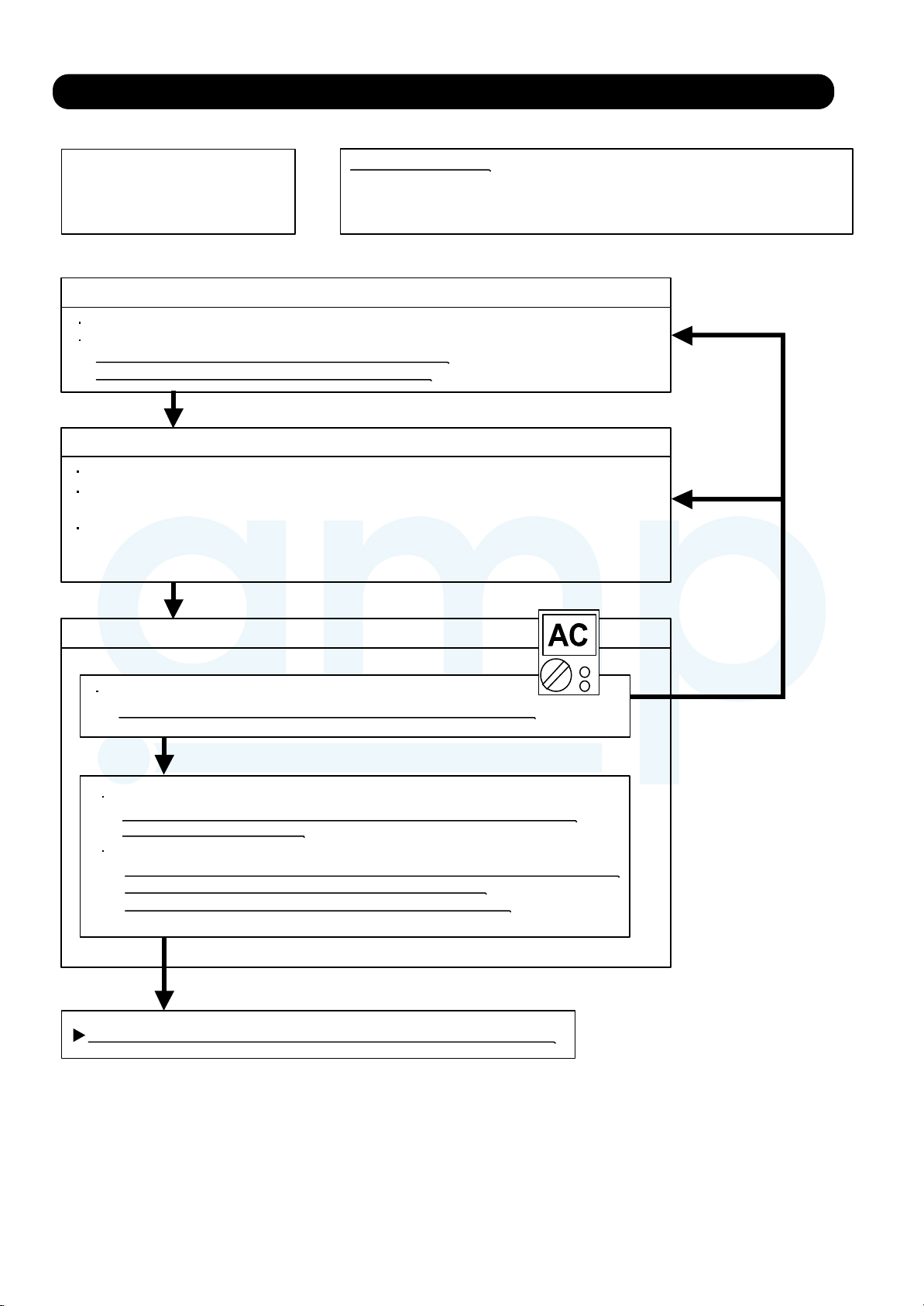
2-3 TROUBLE SHOOTING WITH NO ERROR CODE
AMP Air Conditioning
www.ampair.co.uk | sales@ampair.co.uk
Trouble shooting 34
Forecast of Cause:
1. Power Supply failure 2. External cause
Indoor Unit - No Power
3. Electrical Components defective
Check Point 1 : Check Installation Condition
Isn’t the breaker down?
Check loose or removed connection cable.
>>If abnormal condition is found, correct it by referring
to Installation Manual or Data & Technical Manual.
OKOK
Check Point 2 : Check external cause at Indoor and Outdoor (Voltage drop or Noise)
Instant drop ----- Check if there is a large load electric apparatus in the same circuit.
Momentary power failure ----- Check if there is a defective contact or leak current in
the power supply circuit.
Noise ----- Check if there is any equipment causing harmonic wave near electric line.
(Neon bulb or electric equipment that may cause
Check the complete insulation of grounding.
harmonic wave)
OK
Check Point 3 : Check Electrical Components
Check the voltage of power supply.
>> Check if AC198 - 264V appears at Outdoor Unit Terminal L - N.
YESYES
Check Fuse in Filter PCB.
>> If Fuse is open, check if the wiring between Terminal and Filter PCB
is loose, and replace Fuse.
Check Varistor in Filter PCB.
>> If Varistor is defective, there is a possibility of an abnormal power supply.
Check the correct power supply and replace Varistor.
Upon checking the normal power supply, replace Varistor.
OK
If the symptom does not change by above Check 3, replace Main PCB.
NO
02-35
Page 64

Trouble shooting 35
AMP Air Conditioning
www.ampair.co.uk | sales@ampair.co.uk
Outdoor unit - No Power
Forecast of Cause:
1. Power Supply failure 2. External cause
3. Electrical Components defective
Check Point 1 : Check Installation Condition
Isn’t the breaker down?
Check loose or removed connection cable.
>>If abnormal condition is found, correct it by referring
to Installation Manual or Data & Technical Manual.
OKOK
Check Point 2 : Check external cause at Indoor and Outdoor (Voltage drop or Noise)
Instant drop ----- Check if there is a large load electric apparatus in the same circuit.
Momentary power failure ----- Check if there is a defective contact or leak current in the power supply circuit.
Noise ----- Check if there is any equipment causing harmonic wave near electric line.
(Neon bulb or electric equipment that may cause harmonic wave)
Check the complete insulation of grounding.
OKOK
Check Point 3 : Check Electrical Components
Check the voltage of power supply.
>> Check if AC198 - 264V appears at Outdoor unit Terminal L - N.
YESYES
Check Fuse in Main PCB.
>> If Fuse is open, check if the wiring between Terminal and Main PCB is loose,
and replace Fuse.
OK
If the symptom does not change by above Check 3, replace Main PCB.
NO
02-36
Page 65
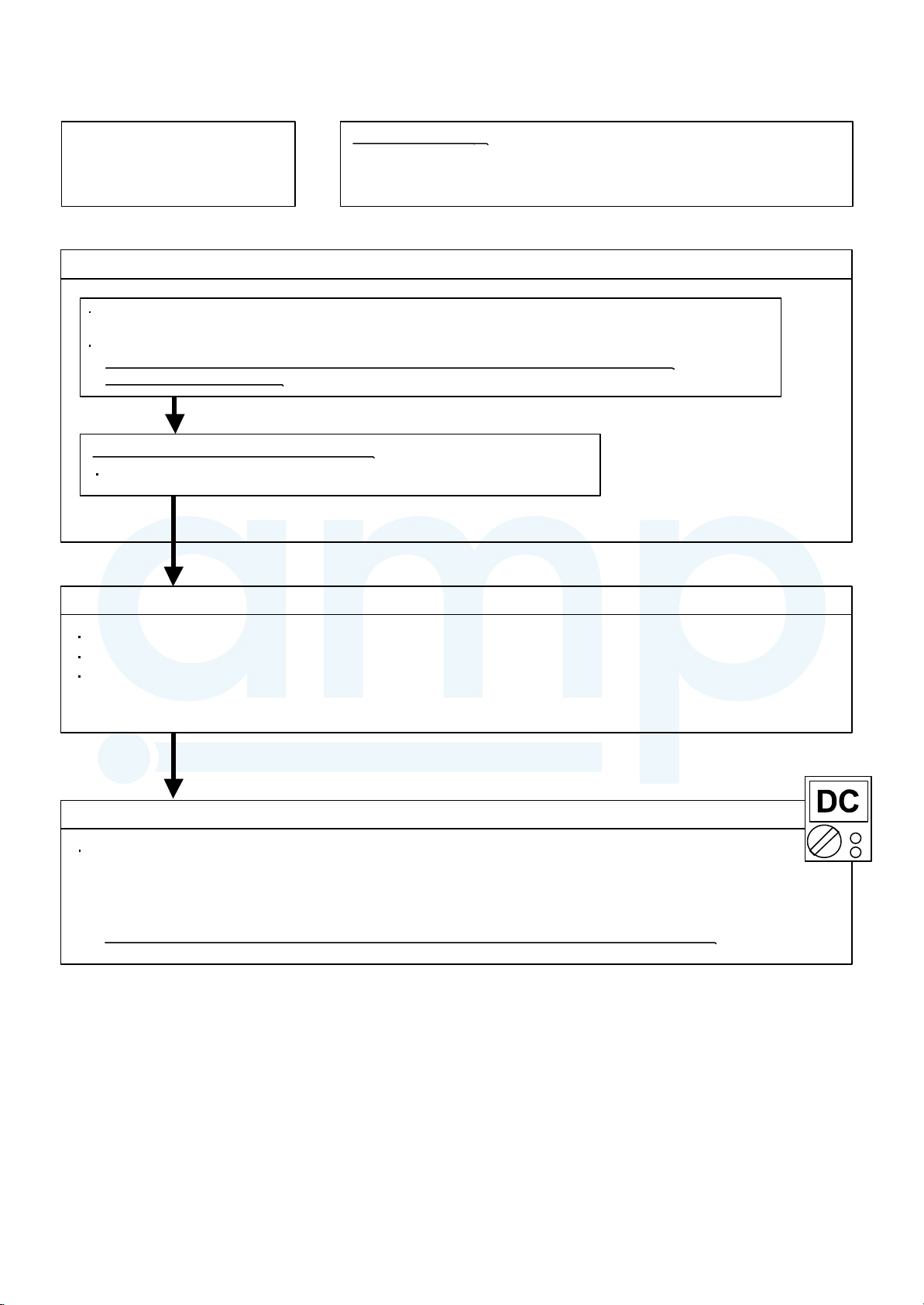
Trouble shooting 36
AMP Air Conditioning
www.ampair.co.uk | sales@ampair.co.uk
Forecast of Cause:
1. Setting/ Connection failure 2. External cause
No Operation (Power is ON)
3. Electrical Component defective
Check Point 1 : Check indoor and outdoor installation condition
Indoor Unit - Check incorrect wiring between Indoor Unit - Remote Control.
Or, check if there is an open cable connection.
Are these Indoor Unit, Outdoor Unit, and Remote Control suitable model numbers to connect?
>> If there is some abnormal condition, correct it by referring to Installation manual and
Data & Technical Manual.
OK
Turn off Power and check/ correct followings.
Is there loose or removed communication line of Indoor Unit and Outdoor Unit?
OK
Check Point 2 : Check external cause at Indoor and Outdoor (Voltage drop or Noise)
Instant drop ----- Check if there is a large load electric apparatus in the same circuit.
Momentary power failure ----- Check if there is a defective contact or leak current in the power supply circuit.
Noise ----- Check if there is any equipment causing harmonic wave near electric line.
(Neon bulb or electric equipment that may cause harmonic wave)
Check the complete insulation of grounding.
OKOK
Check Point 3 : Check Wired Remote Controller and Controller PCB
Check Voltage at CN14 of Controller PCB. (terminal 1-3)
(Power supply to Remote Control)
>> If it is DC13V, Remote Control is failure. (Controller PCB is normal) >> Replace Remote Control
>> If it is DC 0V, Controller PCB is failure. (Check Remote Control once again) >> Replace Controller PCB
>> If the symptom does not change by above Check 1, 2, 3, replace Main PCB of Outdoor unit.
02-37
Page 66

Trouble shooting 37
AMP Air Conditioning
www.ampair.co.uk | sales@ampair.co.uk
No Cooling / No Heating
Forecast of Cause:
1. Indoor Unit error 2. Outdoor Unit error
3. Effect by Surrounding environment
4. Connection Pipe / Connection Wire failure 5. Refrigeration cycle failure
Check Point 1 : Check Indoor Unit
Does Indoor Unit FAN run on HIGH FAN?
Is Air Filter dirty?
Is Heat Exchanger clogged?
Check if Energy save function is operated.
OKOK
Check Point 2 : Check Outdoor Unit Operation
Check if Outdoor Unit is operating
Check any objects that obstruct the air flow route.
Check clogged Heat Exchanger.
Is the Valve open?
OKOK
Check Point 3 : Check Site Condition
Is capacity of Indoor Unit fitted to Room size?
Any windows open? Or direct sunlight ?
OKOK
Check Point 4 :
Check Indoor/ Outdoor Installation Condition
Check connection pipe
(specified pipe length & Pipe diameter?)
Check any loose or removed communication line.
>> If there is an abnormal condition, correct it by
referring to Installation Manual or Data & Technical
Manual.
OKOK
MPa MPa
Check Point 5 : Check Refrigeration Cycle
Check if Strainer is clogged (Refer to the figure at right).
Measure Gas Pressure and if there is a leakage, correct it.
>> When recharging the refrigerant, make sure to perform
vacuuming, and recharge the specified amount.
Check EEV (PARTS INFORMATION 3)
Check Compressor (PARTS INFORMATION 1,2)
Attention
Strainer normally does not have temperature difference
between inlet and outlet as shown in , but if there is a
difference like shown in , there is a possibility of inside
clogged. In this case, replace Strainer.
Pipe (In) Pipe (Out)
Pipe (In) Pipe (Out)
02-38
Page 67

Trouble shooting 38
AMP Air Conditioning
www.ampair.co.uk | sales@ampair.co.uk
Forecast of Cause :
1. Abnormal installation (Indoor/ Outdoor)
Abnormal Noise
2. Fan failure (Indoor/ Outdoor)
3. Compressor failure (Outdoor)
Diagnosis method when Abnormal Noise is occurred
Abnormal noise is coming from Indoor Unit.
(Check and correct followings)
Abnormal noise is coming from Outdoor Unit.
(Check and correct followings)
Is Main Unit installed in stable condition?
Is the installation of Air suction grille and
front panel normal?
OK
Is Fan broken or deformed?
Is the screw of Fan loose?
Is there any object which obstruct the Fan rotation?
Trouble shooting 39
Forecast of Cause:
Water Leaking
Is Main Unit installed in stable condition?
Is Fan Guard installed normally?
OK
Is Fan broken or deformed?
Is the screw of Fan loose?
Is there any object which obstruct the Fan rotation?
OK
Check if
of piping is happening.
vibration noise by loose bolt or contact noise
OK
Is Compressor locked?
>> Check Compressor (PARTS INFORMATION 1,2)
1. Erroneous installation 2. Drain hose failure
Diagnosis method when water leak occurs
Is Main Unit installed in stable condition?
Is Main Unit broken or deformed at the time of
transportation or maintenance?
OKOK
Is Drain Hose connection loose?
Is there a trap in Drain Hose?
Is Drain Hose clogged?
OKOK
Is Fan rotating?
Diagnosis method when water is spitting out.
Is the filter clogged?
OKOK
Check Gas Pressure and correct it
if there was a gas leak.
MPa MPa
02-39
Page 68
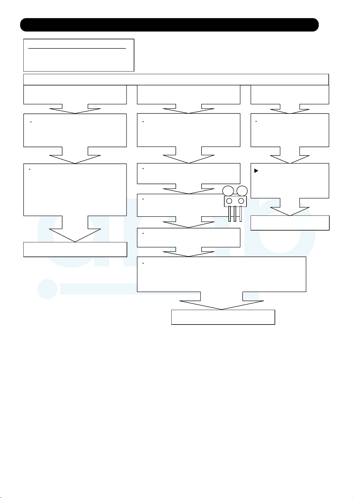
2-4 SERVICE PARTS INFORMATION
AMP Air Conditioning
www.ampair.co.uk | sales@ampair.co.uk
SERVICE PARTS INFORMATION 1
Compressor
Diagnosis method of Compressor ( If Outdoor Unit LED displays Error, refer to Trouble shooting )
Does not start up
Is there open or loose connection
cable?
Check Main PCB, connection of
Compressor, and winding resistance.
(Refer to the next page).
>> If there is no failure, the defect of
Compressor is considered (Locked
compressor due to clogged dirt or
less oil)
Replace Compressor
Stops soon after starting up
Is there open or loose connection
cable?
Is Gas Pipe Valve open?
(Low Pressure is too low)
MPa MPa
Check if Refrigerant is leaking.
(Recharge Refrigerant)
Abnormal noise
Check if vibration noise by
loose bolt or contact noise
of piping is happening.
Defective Compressor
can be considered.
(due to inside dirt clogging
or bro
ken component)
Replace Compressor
Check if Strainer is clogged.
(PARTS INFORMATION 3)
Check Main PCB, connection of Compressor,and winding
resistance. (Refer to the next page).
>> If there is no failure, the defect of Compressor can be
considered. (Compression part broken or valve defective.)
Replace Compressor
02-40
Page 69
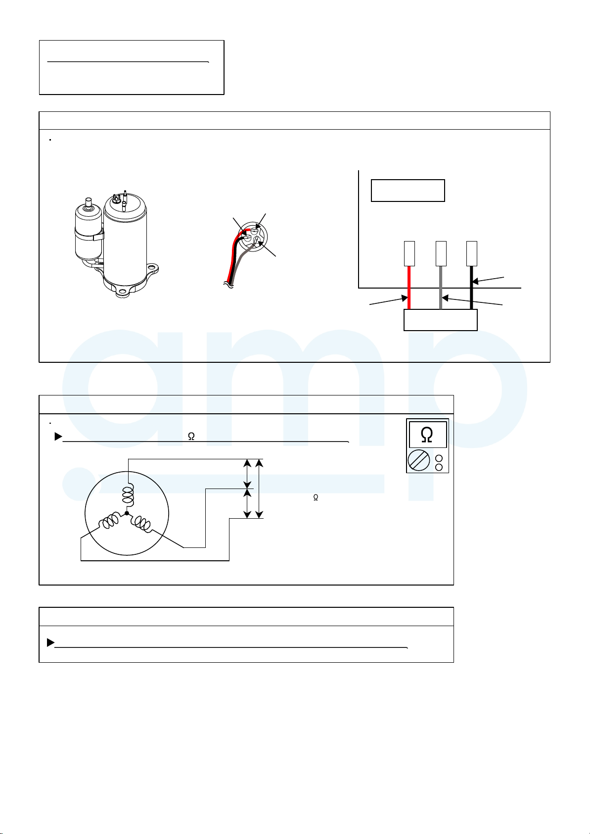
SERVICE PARTS INFORMATION 2
AMP Air Conditioning
www.ampair.co.uk | sales@ampair.co.uk
Inverter Compressor
Check Point 1 : Check Connection
Check terminal connection of Compressor
(loose or incorrect wiring)
Terminal cover opened
T(W)
(BLACK)
R(U)
(RED)
S(V)
(WHITE)
Check Point 2 : Check Winding Resistance
Check winding resistance of each terminal
If the resistance value is 0 or infinite, replace Compressor.
U
RED
Main PCB
W 7
(U)
W 8 W 9
(W) (V)
BLACK
WHITE
Compressor
Resistance Value :
at 20°C
0.818
W
V
Check Point 3 : Replace Main PCB
If the symptom does not change with above Check 1, 2, replace Main PCB.
02-41
Page 70

SERVICE PARTS INFORMATION 3
AMP Air Conditioning
www.ampair.co.uk | sales@ampair.co.uk
Outdoor unit Electronic Expansion Valve
( EEV )
Check Point 1 : Check Connections
Check connection of connector
( Loose connector or open cable )
EXPANSION
VALVE COIL
EV
CN40
1
2
3
4
5
RED
BLUE
ORANGE
YELLOW
WHITE
Check Point 2 : Check Coil of EEV
Remove connector, check each winding
resistance of Coil.
Read wire
Resistance value
Check Point 3 : Check Noise at start up
Turn on Power and check operation noise.
If an abnormal noise does not show,
replace Main PCB.
White - Red
Yellow - Red
Orange - Red
46
at
4
20°C
Check Point 4 : Check Voltage from Main PCB.
Remove Connector and check Voltage (DC12V)
If it does not appear, replace Main PCB.
Blue - Red
If Resistance value is abnormal, replace EEV.
Check Point 5 : Check Opening and Closing Operation of Valve
When Valve is closed,
it has a temp. difference between Inlet and Outlet.
CLOSE
Example : Hot Gas
If it is open,
it has no temp. difference between Inlet and Outlet.
OPEN
Example : Hot Gas
DC
Pipe (In)
Check Point 6 : Check Strainer
Strainer normally does not have temperature difference between inlet and outlet as shown in ,
but if there is a difference as shown in , there is a possibility of inside clogged. In this case, replace Strainer.
Pipe (In) Pipe (Out)
Pipe (Out)
Pipe (In)
Pipe (Out)
Pipe (In) Pipe (Out)
02-42
Page 71

SERVICE PARTS INFORMATION 4
AMP Air Conditioning
www.ampair.co.uk | sales@ampair.co.uk
Indoor unit fan motor
Check Point 1 : Check rotation of Fan
Rotate the fan by hand when operation is off.
(Check if fan is caught, dropped off or locked motor)
>>If Fan or Bearing is abnormal, replace it.
Check Point 2 : Check resistance of Indoor unit Fan Motor
Refer to below. Circuit-test "Vm" and "GND" terminal.
(Vm: DC voltage, GND: Earth terminal)
>>If they are short-circuited (below 300 k ), replace Outdoor fan motor and Main PCB.
Pin number
(wire color)
1 (Red)
2
3 No function
4 (Black)
5 (White)
6 (Yellow)
7 (Brown) Feed back (FG)
Terminal function
(symbol)
DC voltage(Vm)
No function
(GND)
Control voltage (Vcc)
Speed command (Vsp)
SERVICE PARTS INFORMATION 5
Outdoor unit fan motor
Check Point 1 : Check rotation of Fan
Rotate the fan by hand when operation is off.
(Check if fan is caught, dropped off or locked motor)
>>If Fan or Bearing is abnormal, replace it.
Check Point 2 : Check resistance of Outdoor Fan Motor
Refer to below. Circuit-test "Vm" and "GND" terminal.
(Vm: DC voltage, GND: Earth terminal)
>>If they are short-circuited (below 300 k ), replace Outdoor fan motor and Main PCB.
Pin number
(wire color)
1 (Red)
2
3 No function
4 (Black)
5 (White)
6 (Yellow)
7 (Brown) Feed back (FG)
Terminal function
(symbol)
DC voltage (Vm)
No function
Earth terminal (GND)
Control voltage (Vcc)
Speed command (Vsp)
02-43
Page 72

SERVICE PARTS INFORMATION 8
AMP Air Conditioning
www.ampair.co.uk | sales@ampair.co.uk
Thermistor
Check Point : Check Thermistor resistance value
Remove connector and check Thermistor resistance value.
Temperature
[°C]
- 20
- 10
- 5
0
5
10
15
20
25
30
40
50
60
70
80
90
100
110
120
Applicable
Thermistors
Thermistor A Thermistor B Thermistor C Thermistor D
---
---
---
168.6
129.8
100.9
79.1
62.6
49.8
40.0
26.3
17.8
12.3
8.7
6.3
4.6
3.4
2.6
2.0
Discharge temp. TH
Compressor temp. TH
Resistance Value [ k ]
---
27.8
21.0
16.1
12.4
9.6
7.6
6.0
4.8
3.8
2.5
1.7
1.2
---
---
---
---
---
--Outdoor temp. TH Heat sink temp. THHeat exchanger. TH
105.4
58.2
44.0
33.6
25.9
20.2
15.8
12.5
10.0
8.0
5
3.6
---
---
---
---
---
---
---
---
27.4
20.7
15.8
12.2
9.5
7.5
5.9
4.7
3.8
.3
2.5
1.7
1.2
0.8
0.6
0.4
0.3
---
---
02-44
Page 73

3-3-17,Suenaga,Takatsu-ku,Kawasaki 213-8502,Japan
AMP Air Conditioning
www.ampair.co.uk | sales@ampair.co.uk
Dec. 2015 Printed in Japan
 Loading...