

Page 1
SPLIT TYPE
ROOM AIR CONDITIONER
DUCT
type
Models Indoor unit Outdoor unit
AR*A12LATN
AR*A14LATN
AR*A18LATN
AR*A24LATN
AR*A36LATN
AR*A45LATN
AO*A12LACL
AO*A14LACL
AO*A18LACL
AO*A24LACL
AO*A36LATL
AO*A45LATL
INVERTER
SERVICE
INSTRUCTION
R410A
Page 2

CONTENTS
1. SPECIFICATIONS
SPECIFICATIONS.......................................................................................................... 01-01
2. DIMENSIONS
DIMENSIONS.................................................................................................................. 02-01
3. REFRIGERANT SYSTEM DIAGRAM
REFRIGERANT CIRCUIT............................................................................................... 03-01
4. CIRCUIT DIAGRAM
CIRCUIT DIAGRAM........................................................................................................ 04-01
5. DESCRIPTION OF EACH CONTROL OPERATION
5-1-1 COOLING CAPACITY CONTROL......................................................................
5-1 COOLING OPERATION............................................................................................
5-4 AUTO CHANGEOVER OPERATION........................................................................
5-5 INDOOR FAN CONTROL.........................................................................................
5-6 OUTDOOR FAN CONTROL......................................................................................
05-01
05-01
5-2-1 HEATING CAPACITY CONTROL......................................................................
5-2 HEATING OPERATION.............................................................................................
05-02
05-02
5-3-1 INDOOR UNIT CONTROL.................................................................................
5-3 DRY OPERATION......................................................................................................
05-03
05-03
05-04
05-05
05-08
5-7 COMPRESSOR CONTROL......................................................................................
05-10
5-8 TIMER OPERATION CONTROL...............................................................................
05-11
5-9 ELECTRONIC EXPANSION VALVE CONTROL....................................................
05-13
5-10 TEST OPERATION CONTROL...............................................................................
05-13
5-11 PREVENT TO START FOR 3 MINUTES (3 MINUTES ST)....................................
05-13
5-12 4-WAY VALVE EXTENSION SELECT....................................................................
05-14
5-13 AUTO RESTART.....................................................................................................
05-14
5-14 PUMP DOWN (For AR*30/ 36/ 45LUAN/ 45/ 54LUAK)..........................................
05-14
5-15 COMPRESSOR PREHEATING...............................................................................
05-14
5-17 EXTERNAL ELECTRICAL HEATER CONTROL....................................................
05-15
5-16 FRESH AIR CONTROL...........................................................................................
05-15
5-20 ECONOMY OPERATION.........................................................................................
05-19
5-21 VARIOUS PROTECTIONS......................................................................................
05-20
5-22 FORCED COOLING OPERATION..........................................................................
05-22
5-23 COMPRESSOR STOP CONTROL..........................................................................
05-22
5-18 DEFROST OPERATION CONTROL.......................................................................
05-16
5-19 OFF DEFROST OPERATION CONTROL...............................................................
05-18
Page 3

6. REFRIGERANT CAUTION -R410A-
6-1 R410A TOOLS............................................................................................................ 06-01
6-2 PRECAUTION FOR INSTALLATION.........................................................................
06-02
6-3 PRECAUTION FOR SERVICING...............................................................................
06-04
6-4 NEW REFRIGERANT R410A.....................................................................................
06-05
6-5 DEFFERENCE FROM CONVENTIONAL MODEL (R22) AND PRECAUTIONS.......
06-08
8. APPENDING DATA
9. INSTALLATION MANUAL
8-1 CAPACITY TABLE..................................................................................................... 08-01
8-2 OPERATION RANGE.................................................................................................
08-07
8-3 ELECTRIC CHARACTERISTICS...............................................................................
08-08
8-4 SAFETY DEVICE........................................................................................................
08-10
8-5 FUNCTION SETTING.................................................................................................
08-10
7-1-2 OUTDOOR UNIT DISPLAY................................................................................
7-1-1 WIRED REMOTE CONTROLLER DISPLAY......................................................
7-1 ERROR DISPLAY......................................................................................................
7. TROUBLE SHOOTING
7-2 TROUBLE SHOOTING WITH ERROR CODE..........................................................
7-3 TROUBLE SHOOTING WITH NO ERROR CODE....................................................
7-4 SERVICE PARTS INFORMATION............................................................................
07-01
07-01
8-5-1 INDOOR UNIT....................................................................................................
08-12
8-5-2 Procedures to change the Function Setting........................................................
08-14
8-5-3 WIRED REMOTE CONTROLLER......................................................................
08-15
07-03
07-30
07-04
07-35
Page 4

1 . SPECIFICATIONS
R410A
DUCT type
INVERTER
Page 5
01-01
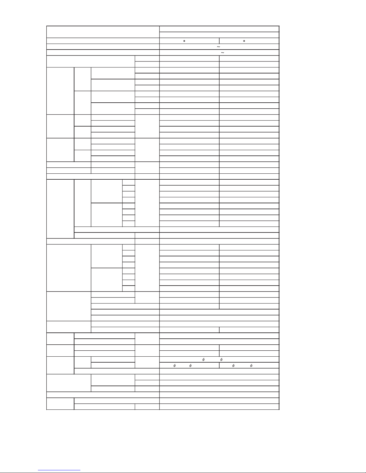
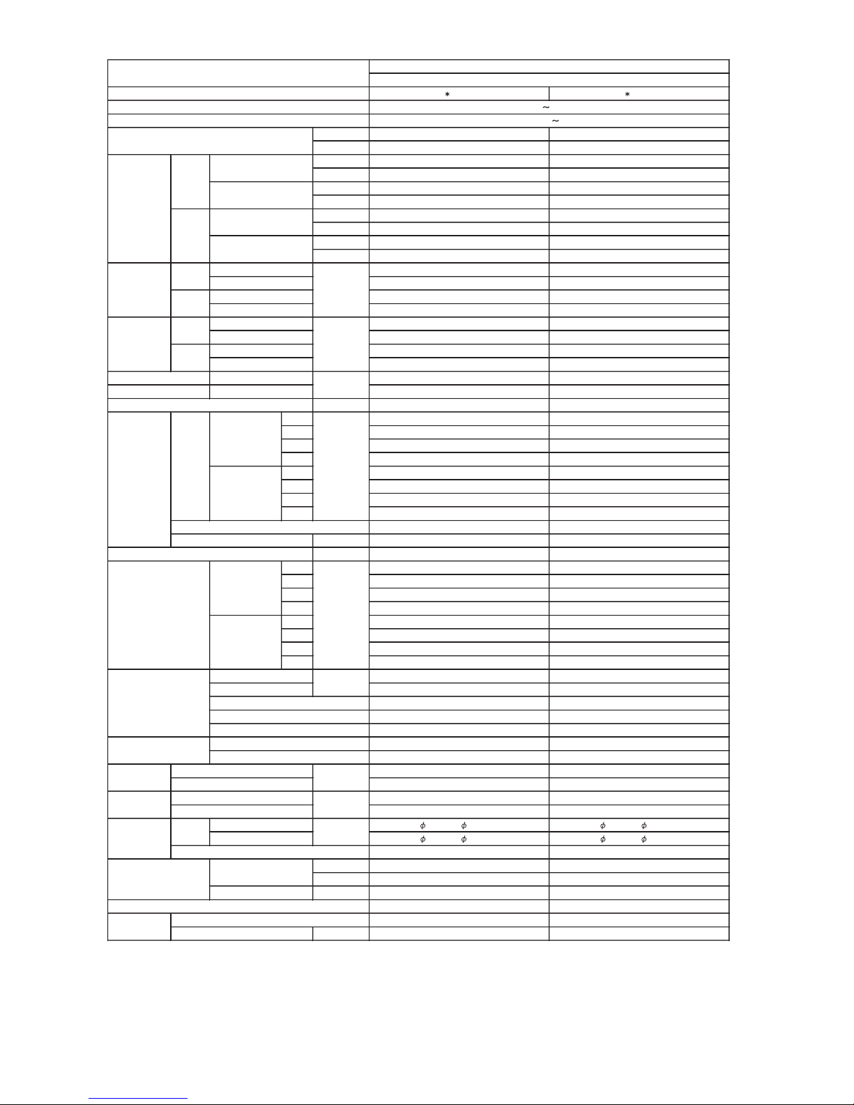
1. SPECIFICATIONS FOR INDOOR UNIT
AR A12LATN AR A14LATN
Cooling A A
Heating A A
kW 3.5 4.3
BTU/h 11950 14650
kW 0.9 - 4.4 0.9 - 5.4
BTU/h 3100 - 15000 3100 - 18400
kW 4.1 5.0
BTU/h 14000 17050
kW 0.9 - 5.7 0.9 - 6.5
BTU/h 3100 - 19400 3100 - 22100
1.05 1.33
1.73 2.07
1.11 1.34
2.30 2.88
4.6 5.8
7.5 9.0
4.9 5.9
10.0 12.5
EER 3.33 3.21
COP 3.69 3.71
l/h (pints/h) 1.3 ( 2.3 ) 1.5 ( 2.6 )
High 720 820
Med 630 720
Low 560 610
Quiet 480 550
High 720 820
Med 630 720
Low 560 610
Quiet 480 550
Type × Q'ty
Motor output W
Recommended static pressure Pa
High 32 33
Med 30 31
Low 28 29
Quiet 26 27
High 32 33
Med 30 31
Low 28 29
Quiet 26 27
Dimensions (H × W × D) 294 × 700 × 26.6 294 × 700 × 39.9
Fin pitch 1.30 1.30
Rows x Stages 2 × 14 3 × 14
Pipe type
Fin type
Material
Colour - -
Net
Gross
Net 23 ( 51 ) 23 ( 51 )
Gross 27 ( 60 ) 27 ( 60 )
Liquid
Gas
9.52 ( 3 / 8 in.) 12.70 ( 1 / 2 in.)
Method
°C
%RH
Heating °C
mm
Note :
Specifications are based on the following conditions.
Cooling : Indoor temperature of 27 °CDB / 19 °CWB.and outdoor temperature of 35 °CDB/24 °CWB.
Heating : Indoor temperature of 20 °CDB / 15 °CWB.and outdoor temperature of 7 °CDB/6 °CWB.
Standard static pressure : 0 Pa
Pipe length : 7.5 m, Height difference : 0 m.(Outdoor unit - Indoor unit)
Sound pressure level : Install a 2m duct to the outlet port and a 1m duct to the suction port and measure.
*The maximum current and the maximum input value are the maximum values when operated within the operation (temperature) range.
dB(A)
Remote controller type
Drain pipe
Material
Size
Operation range
Cooling
kg(lb.)
Connection pipe
SizemmWeight
m3/h
Fan
Dimensions
( H×W ×D )
mm
Airflow
rate
Enclosure
Heat exchanger type
Sound pressure level
Heating
Cooling
Heating
Heating
Cooling
Moisture removal
Cooling
Heating
Rated
*Max.
Rated
*Max.
kW/kW
Input power
Cooling
kW
Heating
Rated
*Max.
Current
Cooling
A
Power source
Available voltage range
Capacity
Cooling
Heating
European energy label
Type
Model name
mm
Rated
Min.-Max.
Rated
Min.-Max.
Rated
*Max.
DUCTED MODEL
INVERTER HEATPUMP
230V 50Hz
198-264V 50Hz
Sirocco × 2
60
0 to 90
Copper
Aluminium
Steel
217 × 953 × 595
324 × 1075 × 686
Wired
PS
Outer diameter : 26.0 / Inner diameter : 21.5
6.35 ( 1 / 4 in.)
Flare
18 to 32
80 or less
30 or less
Page 6
01-02
DUCTED MODEL
INVERTER HEATPUMP
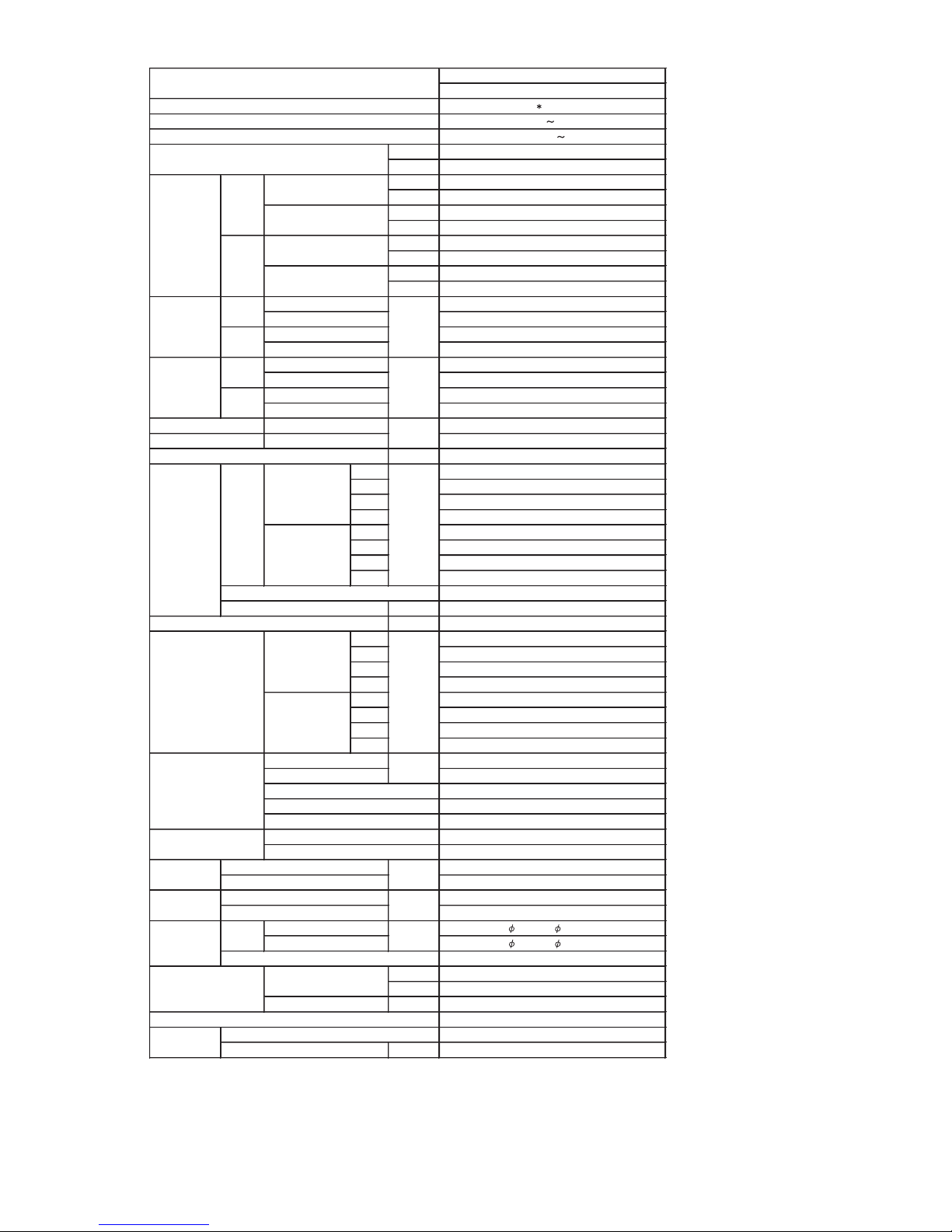
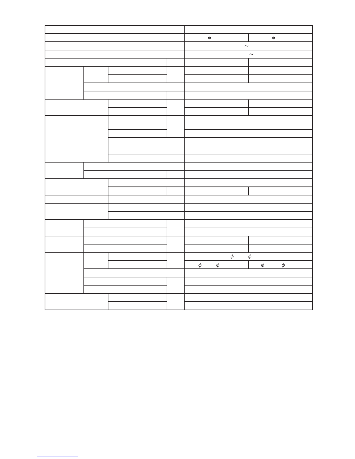
AR A18LATN
230V 50Hz
198-264V 50Hz
Cooling A
Heating A
kW 5.2
BTU/h 17700
kW 0.9 - 5.9
BTU/h 3100 - 20100
kW 6.0
BTU/h 20500
kW 0.9 - 7.5
BTU/h 3100 - 25600
1.62
0.09 - 1.80
1.66
0.09 - 2.46
7.1
9.0
7.3
10.8
EER 3.21
COP 3.61
l/h (pints/h) 2.0 ( 3.5 )
High 820
Med 720
Low 610
Quiet 550
High 820
Med 720
Low 610
Quiet 550
Type × Q'ty Sirocco × 2
Motor output W 60
Recommended static pressure Pa 0 to 90
High 33
Med 31
Low 29
Quiet 27
High 33
Med 31
Low 29
Quiet 27
Dimensions (H × W × D) 294 × 700 × 39.9
Fin pich 1.30
Rows x Stages 3 × 14
Pipe type Copper
Fin type Aluminium
Material Steel
Colour
-
Net 217 × 953 × 595
Gross 324 × 1075 × 686
Net 23 ( 51 )
Gross 27 ( 60 )
Liquid
6.35 ( 1 / 4 in.)
Gas
12.70 ( 1 / 2 in.)
Method Flare
°C 18 to 32
%RH 80 or less
Heating °C 30 or less
Wired
PS
mm Outer diameter: 26.0 / Inner diameter: 21.5
Note :
Specifications are based on the following conditions.
Cooling : Indoor temperature of 27 °CDB / 19 °CWB.and outdoor temperature of 35 °CDB/24 °CWB.
Heating : Indoor temperature of 20 °CDB / 15 °CWB.and outdoor temperature of 7 °CDB/6 °CWB.
Standard static pressure : 0 Pa
Pipe length : 7.5 m, Height difference : 0 m.(Outdoor unit - Indoor unit)
Sound pressure level : Install a 2m duct to the outlet port and a 1m duct to the suction poit and measure.
Type
Model name
mm
Rated
Min-Max
Rated
Min-Max
Rated
Min-Max
Power source
Available voltage range
Capacity
Cooling
Heating
European energy label
kW/kW
Input power
Cooling
kW
Heating
Rated
Min-Max
Current
Cooling
A
Rated
Max
Rated
Max
Heating
Cooling
Heating
Heating
Cooling
Moisture removal
Cooling
Heating
mm
Weight
m3/h
Fan
Dimensions
( H × W × D )
mm
Airflow
rate
Enclosure
Heat exchanger type
Sound pressure level
dB(A)
Remote controller type
Drain pipe
Material
Size
Operation range
Cooling
kg(lb.)
Connection pipe
Size
Page 7
01-03
DUCTED MODEL
INVERTER HEATPUMP
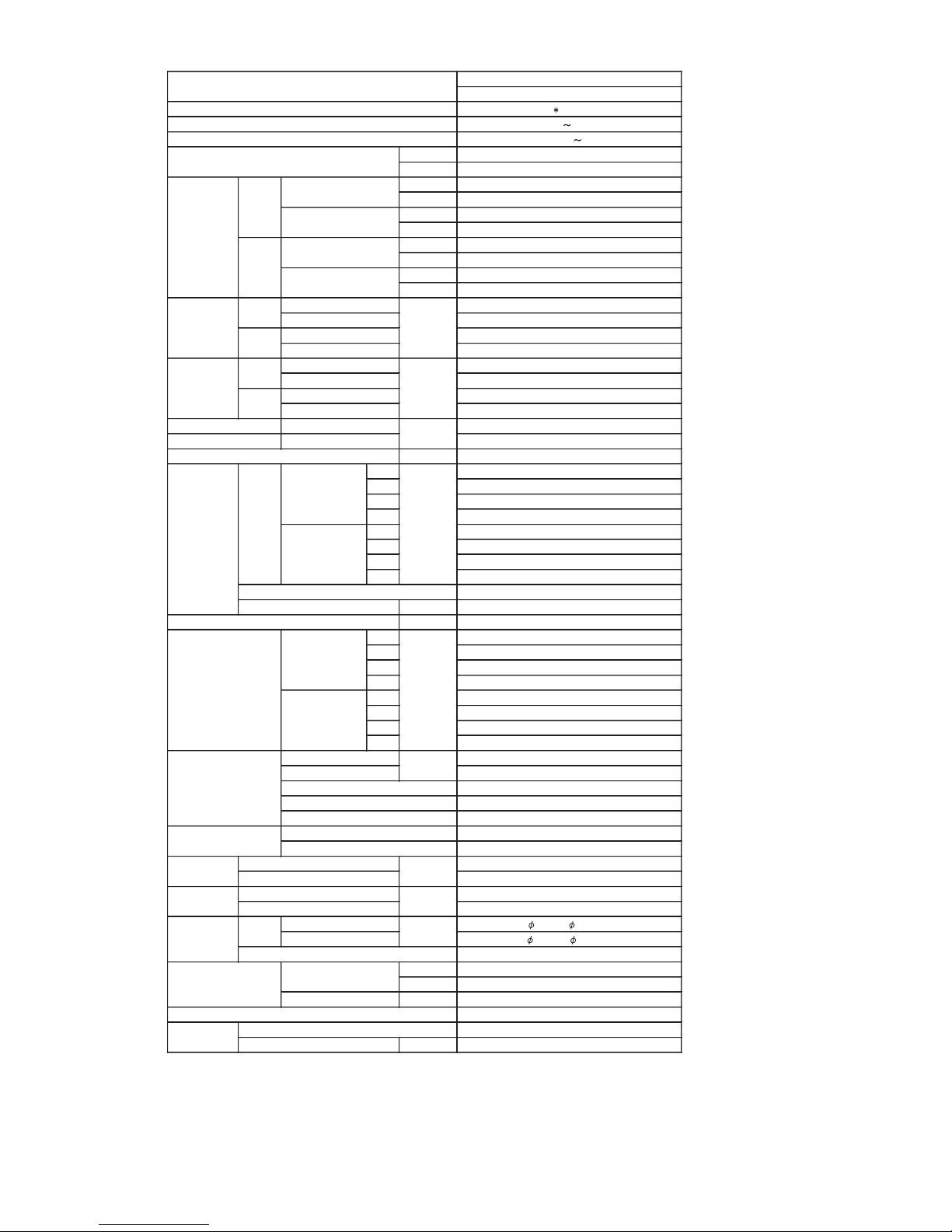
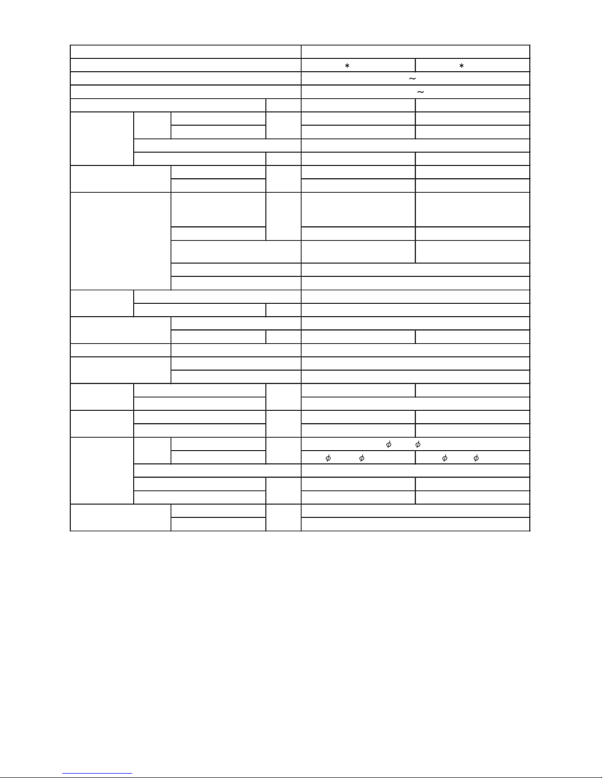
AR A24LATN
230V 50Hz
198-264V 50Hz
Cooling A
Heating A
kW 7.1
BTU/h 24200
kW 0.9 - 8.0
BTU/h 3100 - 27300
kW 8.0
BTU/h 27300
kW 0.9 - 9.1
BTU/h 3100 - 31000
2.21
0.09 - 2.62
2.21
0.09 - 2.77
9.7
11.5
9.7
12.2
EER 3.21
COP 3.61
l/h (pints/h) 2.5 (4.4)
High 1100
Med 950
Low 800
Quiet 600
High 1100
Med 950
Low 800
Quiet 600
Type × Q'ty Sirocco × 2
Motor output W 115
Recommended static pressure Pa 30 to 150
High 31
Med 29
Low 27
Quiet 25
High 31
Med 29
Low 27
Quiet 25
Dimensions (H × W × D) 294 × 1000 × 39.9
Fin pich 1.40
Rows x Stages 3 × 14
Pipe type Copper
Fin type Aluminium
Material Steel
Colour
-
Net 270 × 1135 × 700
Gross 300 × 1300 × 790
Net 38 ( 84 )
Gross 45 ( 99 )
Liquid
6.35 ( 1 / 4 in.)
Gas
15.88 ( 5 / 8 in.)
Method Flare
°C 18 to 32
%RH 80 or less
Heating °C 30 or less
Wired
Steel
mm Outer diameter: 38.0 / Inner diameter: 36.0
Note :
Specifications are based on the following conditions.
Cooling : Indoor temperature of 27 °CDB / 19 °CWB.and outdoor temperature of 35 °CDB/24 °CWB.
Heating : Indoor temperature of 20 °CDB / 15 °CWB.and outdoor temperature of 7 °CDB/6 °CWB.
Standard static pressure : 30 Pa
Pipe length : 7.5 m, Height difference : 0 m.(Outdoor unit - Indoor unit)
Sound pressure level : Install a 2m duct to the outlet port and a 1m duct to the suction poit and measure.
Type
Model name
mm
Rated
Min-Max
Rated
Min-Max
Rated
Min-Max
Power source
Available voltage range
Capacity
Cooling
Heating
European energy label
kW/kW
Input power
CoolingkWHeating
Rated
Min-Max
Current
Cooling
A
Rated
Max
Rated
Max
Heating
Cooling
Heating
Heating
Cooling
Moisture removal
Cooling
Heating
mm
Weight
m3/h
Fan
Dimensions
( H × W × D )
mm
Airflow
rate
Enclosure
Heat exchanger type
Sound pressure level
dB(A)
Remote controller type
Drain pipe
Material
Size
Operation range
Cooling
kg(lb.)
Connection pipe
Size
Page 8
01-04
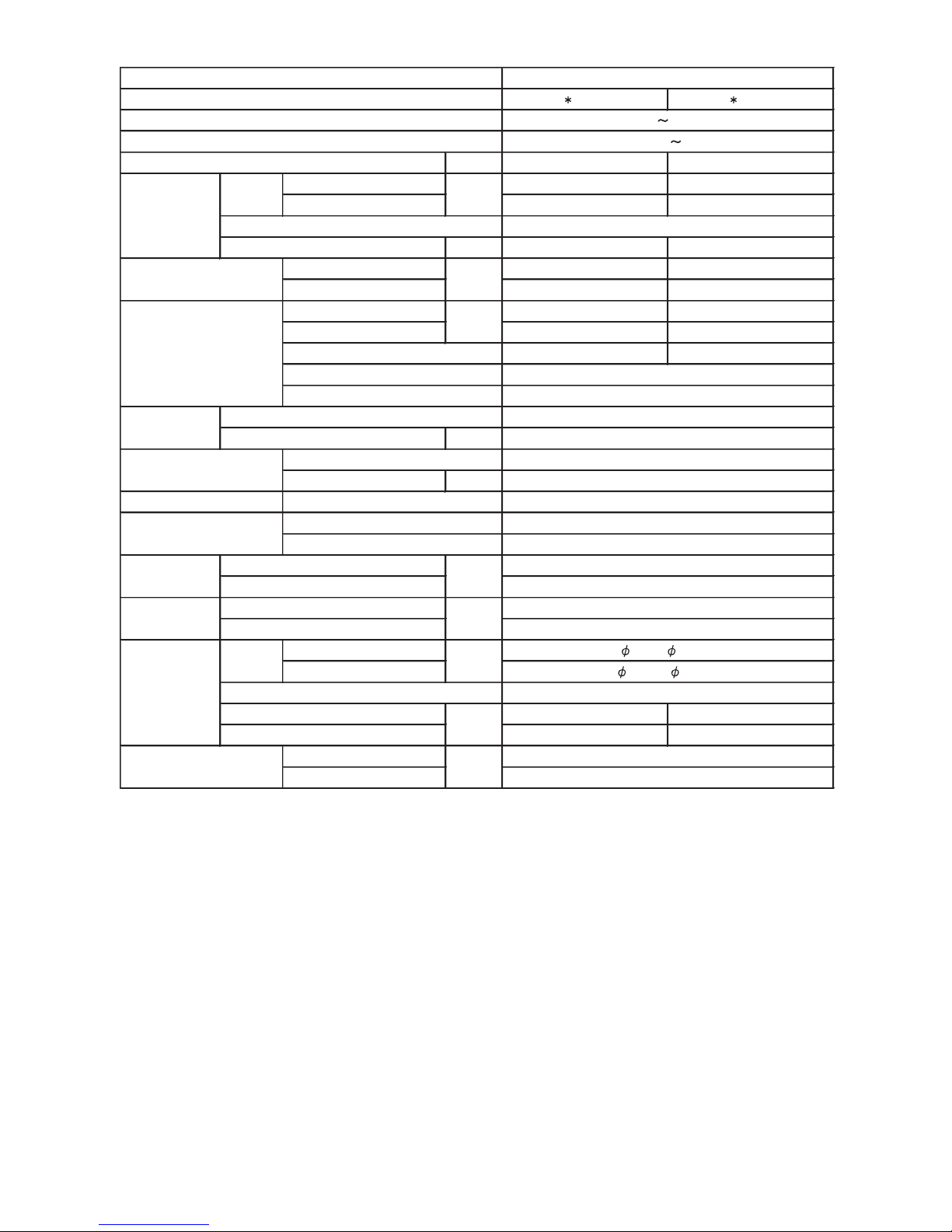
AR A36LATN AR A45LATN
Cooling A A
Heating A A
kW 10.0 12.5
BTU/h 34100 42700
kW 3.8 - 11.2 4.0 - 14.0
BTU/h 13000 - 38200 13700 - 47800
kW 11.2 14.0
BTU/h 38200 47800
kW 4.0 - 14.0 4.2 - 16.2
BTU/h 13700 - 47800 14300 - 55300
3.11 3.89
4.33 4.56
3.02 3.77
4.33 4.56
13.6 17.0
19.0 20.0
13.2 16.5
19.0 20.0
EER 3.21 3.21
COP 3.71 3.71
l/h (pints/h) 3.0 (5.3) 3.5 (6.2)
High 2020 2250
Med 1710 1710
Low 1340 1340
Quiet 1020 1020
High 2020 2250
Med 1710 1710
Low 1340 1340
Quiet 1020 1020
Type × Q'ty Sirocco × 2 Sirocco × 2
Motor output W 197 197
Recommended static pressure Pa 30 to 150 30 to 150
High 42 44
Med 37 38
Low 32 33
Quiet 29 29
High 42 44
Med 37 38
Low 32 33
Quiet 29 29
Dimensions (H × W × D) 294 × 1000 × 53.2 294 × 1000 × 53.2
Fin pitch 1.40 1.40
Rows x Stages 4 × 14 4 × 14
Pipe type Copper Copper
Fin type Aluminium Aluminium
Material Steel Steel
Colour - -
Net 270 × 1135 × 700 270 × 1135 × 700
Gross 300 × 1300 × 790 300 × 1300 × 790
Net 41 ( 90 ) 41 ( 90 )
Gross 48 ( 106 ) 48 ( 106 )
Liquid
9.52 ( 3 / 8 in.) 9.52 ( 3 / 8 in.)
Gas
15.88 ( 5 / 8 in.) 15.88 ( 5 / 8 in.)
Method Flare Flare
°C 18 to 32 18 to 32
%RH 80 or less 80 or less
Heating °C 30 or less 30 or less
Wired Wired
Steel Steel
mm Outer diameter : 38.0 / Inner diameter : 36.0 Outer diameter : 38.0 / Inner diameter : 36.0
Note :
Specifications are based on the following conditions.
Cooling : Indoor temperature of 27 °CDB / 19 °CWB.and outdoor temperature of 35 °CDB/24 °CWB.
Heating : Indoor temperature of 20 °CDB / 15 °CWB.and outdoor temperature of 7 °CDB/6 °CWB.
Standard static pressure : 30Pa
Pipe length : 7.5 m, Height difference : 0 m.(Outdoor unit - Indoor unit)
Sound pressure level : Install a 2m duct to the outlet port and a 1m duct to the suction poit and measure.
*The maximum current and the maximum input value are the maximum values when operated within the operation (temperature) range.
DUCTED MODEL
INVERTER HEATPUMP
230V 50Hz
198-264V 50Hz
dB(A)
Remote controller type
Drain pipe
Material
Size
Operation range
Cooling
kg(lb.)
Connection pipe
SizemmWeight
m3/h
Fan
Dimensions
( H × W × D )
mm
Airflow
rate
Enclosure
Heat exchanger type
Sound pressure level
Heating
Cooling
Heating
Heating
Cooling
Moisture removal
Cooling
Heating
Rated
*Max.
Rated
*Max.
kW/kW
Input power
Cooling
kW
Heating
Rated
*Max.
Current
Cooling
A
Power source
Available voltage range
Capacity
Cooling
Heating
European energy label
Type
Model name
mm
Rated
Min.-Max.
Rated
Min.-Max.
Rated
*Max.
Page 9
01-05
2. SPECIFICATIONS FOR OUTDOOR UNIT
AO A12LACL AO A14LACL
A 4.9 5.9
1780 1910
1630 1740
W
47 49
48 49
W
g 1150 1250
40 (88) 40 (88)
44 (97) 44 (97)
9.52 ( 3/8 in.) 12.70 ( 1/2 in.)
Note :
Specifications are based on the following conditions.
Cooling : Indoor temperature of 27°CDB/19°CWB. and outdoor temperature of 35°CDB/24°CWB.
Heating : Indoor temperature of 20°CDB/15°CWB. and outdoor temperature of 7°CDB/6°CWB.
Pipe length : 7.5 m, Height difference : 0 m. (Outdoor unit - Indoor unit)
Cooling
Heating
Type
Gross
Liquid
Gas
Method
Colour
Net
Gross
Net
Motor output
Type
Charge
Material
Rows x Stages
Pipe type
Fin type
Type × Q'ty
Motor output
Cooling
Heating
Dimensions (H × W × D)
Type
Model name
Power source
Available voltage range
578 × 790 × 300
25 (chargeless : 15)
15
546 × 876 × 18.2
546 × 842 × 18.2
1.30
2 × 26
Copper
Aluminium
Steel sheet
Beige (10YR7.5/1.0NN)
54
°C
Operation range
Fan
Airflow
rate
m3/h
dB(A)
mm
mm
Weight
kg(lb.)
Dimensions
(H × W × D)
Refrigerant oil
Enclosure
Heat exchanger type
Fin pitch
Compressor
Refrigerant
Sound pressure level
Starting current
Cooling
Heating
Type × Q'ty
m
Connection pipe
Size
mm
Max. length
Max. height difference
INVERTER HEATPUMP
230V 50Hz
198-264V 50Hz
Propeller × 1
Twin Rotary × 1
1100
R410A
POE
Flare
-10 to 46
-15 to 24
648 × 910 × 380
6.35 ( 1/4 in.)
Page 10
01-06
AO A18LACL AO A24LACL
A 7.7 10.0
2000 2470
1910 2470
W 54 65
50 52
50 53
546 × 876 × 18.2
546 × 842 × 18.2
546 × 866 × 18.2
546 × 832 × 18.2
504 × 589 × 18.2
1.30 1.40
2 × 26
2 × 26
1 × 24
W
g 1250 1700
578 × 790 × 300 578 × 790 × 315
40 (88) 44 (97)
44 (97) 48 (106)
12.70 ( 1/2 in.) 15.88( 5/8 in.)
25(chargeless : 15) 30(chargeless : 15)
15 20
Note :
Specifications are based on the following conditions.
Cooling : Indoor temperature of 27°CDB/19°CWB. and outdoor temperature of 35°CDB/24°CWB.
Heating : Indoor temperature of 20°CDB/15°CWB. and outdoor temperature of 7°CDB/6°CWB.
Pipe length : 7.5 m, Height difference : 0 m. (Outdoor unit - Indoor unit)
Cooling
Heating
Dimensions (H × W × D)
Charge
Type
Material
Colour
Motor output
Cooling
Heating
Fin pich
Type
Model name
Power source
Available voltage range
°C
Operation range
Fan
Airflow
rate
m3/h
dB(A)
mm
mm
Weight
kg(lb.)
Dimensions
( H × W × D)
Net
Gross
Net
Gross
Refrigerant oil
Enclosure
Heat exchanger type
Rows x Stages
Pipe type
Fin type
Type × Q'ty
Motor output
Type
Compressor
Refrigerant
Sound pressure level
Type × Q'ty
Starting currente
Cooling
Heating
m
Connection pipe
Size
mm
Liquid
Gas
Method
Max. length
Max. height difference
INVERTER HEATPUMP
230V 50Hz
198-264V 50Hz
Propeller × 1
Copper
Aluminium
Steel sheet
Beige (10YR7.5/1.0NN)
Twin Rotary × 1
1100
R410A
POE
Flare
-10 to 46
-15 to 24
648 × 910 × 380
6.35 ( 1/4 in.)
Page 11
01-07
AO A36LATL AO A45LATL
A 15.0 15.0
6600 6600
6600 6600
W 103 × 2 103 × 2
54 55
55 56
1260 × 900 × 36.4
1260 × 900 × 36.4
1.30 1.30
2 × 60 2 × 60
W
g
50 (chargeless : 20) 50 (chargeless : 20)
30 30
Note :
Specifications are based on the following conditions.
Cooling : Indoor temperature of 27°CDB/19°CWB. and outdoor temperature of 35°CDB/24°CWB.
Heating : Indoor temperature of 20°CDB/15°CWB. and outdoor temperature of 7°CDB/6°CWB.
Pipe length : 7.5 m, Height difference : 0 m. (Outdoor unit - Indoor unit)
Colour
Net
Gross
Motor output
Type
Charge
Type
Material
Motor output
Cooling
Heating
Dimensions (H × W × D)
Type
Model name
Power source
Available voltage range
1290 × 900 × 330
98 (216)
107 (236)
15.88 ( 5/8 in.)
Flare
-15 to 46
-15 to 24
1430 × 1050 × 445
9.52 ( 3/8 in.)
Copper
Aluminium
Steel sheet
Beige (10YR7.5/1.0NN)
Twin Rotary × 1
3750
R410A
POE
3350
INVERTER HEATPUMP
230V 50Hz
198-264V 50Hz
Propeller × 2
m
Connection pipe
Size
mm
Liquid
Gas
Method
Max. length
Max. height difference
Compressor
Refrigerant
Sound pressure level
Starting current
Cooling
Heating
Type × Q'ty
Refrigerant oil
Enclosure
Heat exchanger type
Fin pitch
Rows x Stages
Pipe type
Fin type
Type × Q'ty
mm
Weight
kg(lb.)
Dimensions
(H × W × D)
Net
Gross
°C
Operation range
Fan
Airflow
rate
m3/h
dB(A)
mm
Cooling
Heating
Page 12

2 . DIMENSIONS
R410A
DUCT type
INVERTER
Page 13
02-01
(Unit : mm)
(Unit : mm)
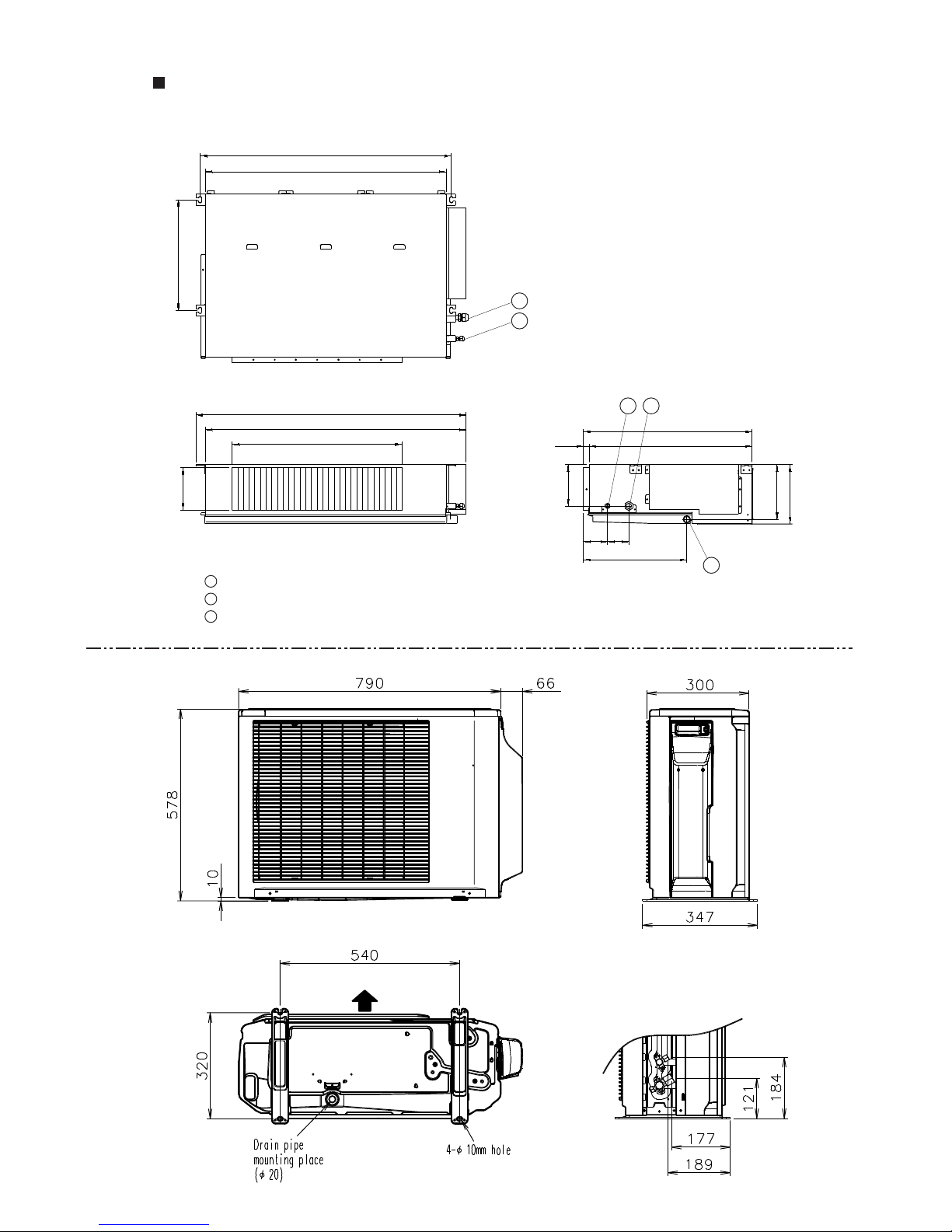
2. DIMENSIONS
MODEL : AR*A12LATN / AO*A12LACL
AR*A14LATN / AO*A14LACL
886
953
850
920
600
150
150
595
57520
85 75
364
390
194
217
1
Refrigerant piping flare connection (Gas)
Refrigerant piping flare connection (Liquid)
Drain piping connection
2
3
12
3
1
2
Top view
Front view
Side view
Air flow
Front view
Side view
Bottom view
Page 14
02-02
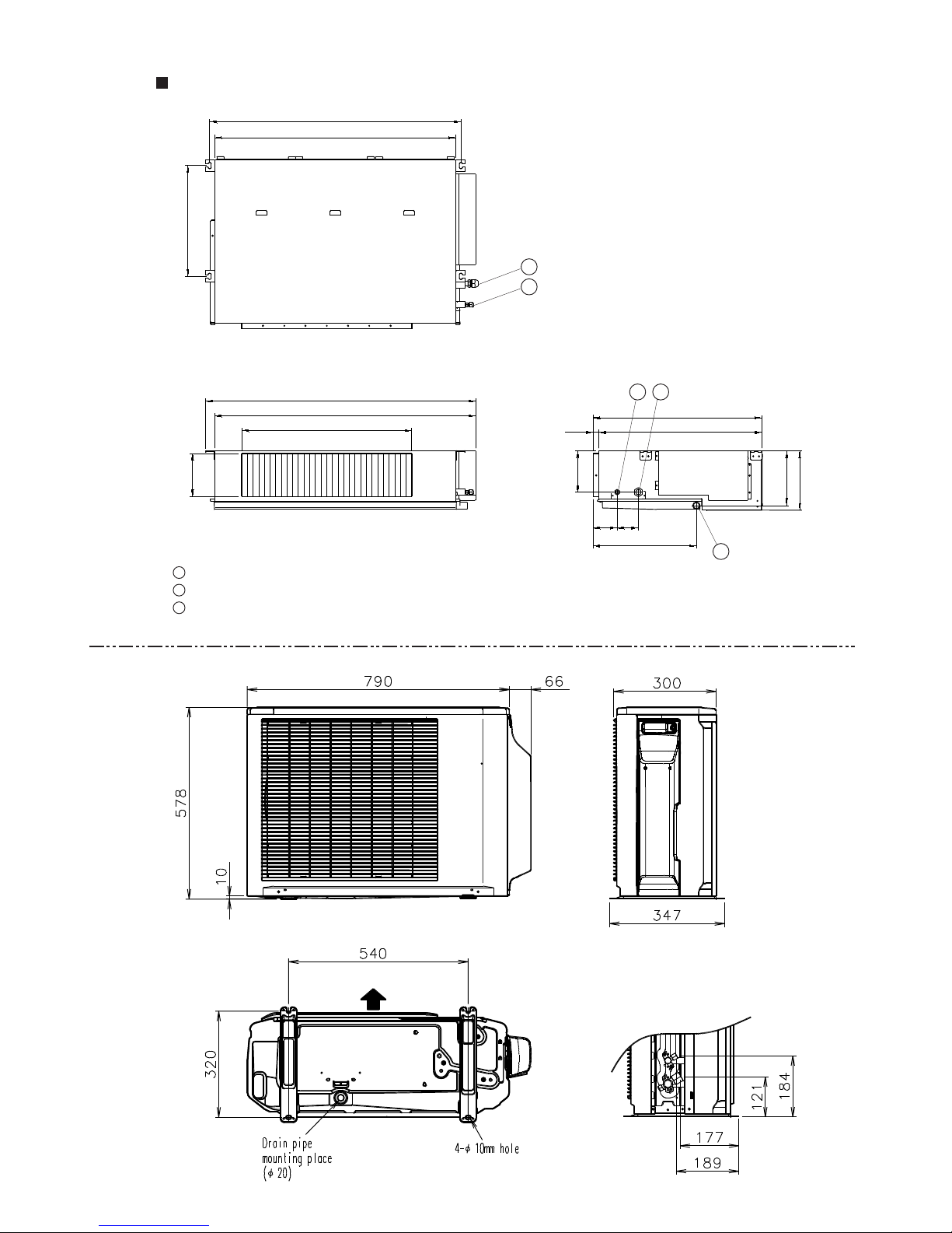
(Unit : mm)
(Unit : mm)
MODEL : AR*A18LATN / AO*A18LACL
886
953
850
920
600
150
150
595
57520
85 75
364
390
194
217
1
Refrigerant piping flare connection (Gas)
Refrigerant piping flare connection (Liquid)
Drain piping connection
2
3
12
3
1
2
Top view
Front view
Side view
Air flow
Front view
Side view
Bottom view
Page 15
02-03
(Unit : mm)
(Unit : mm)
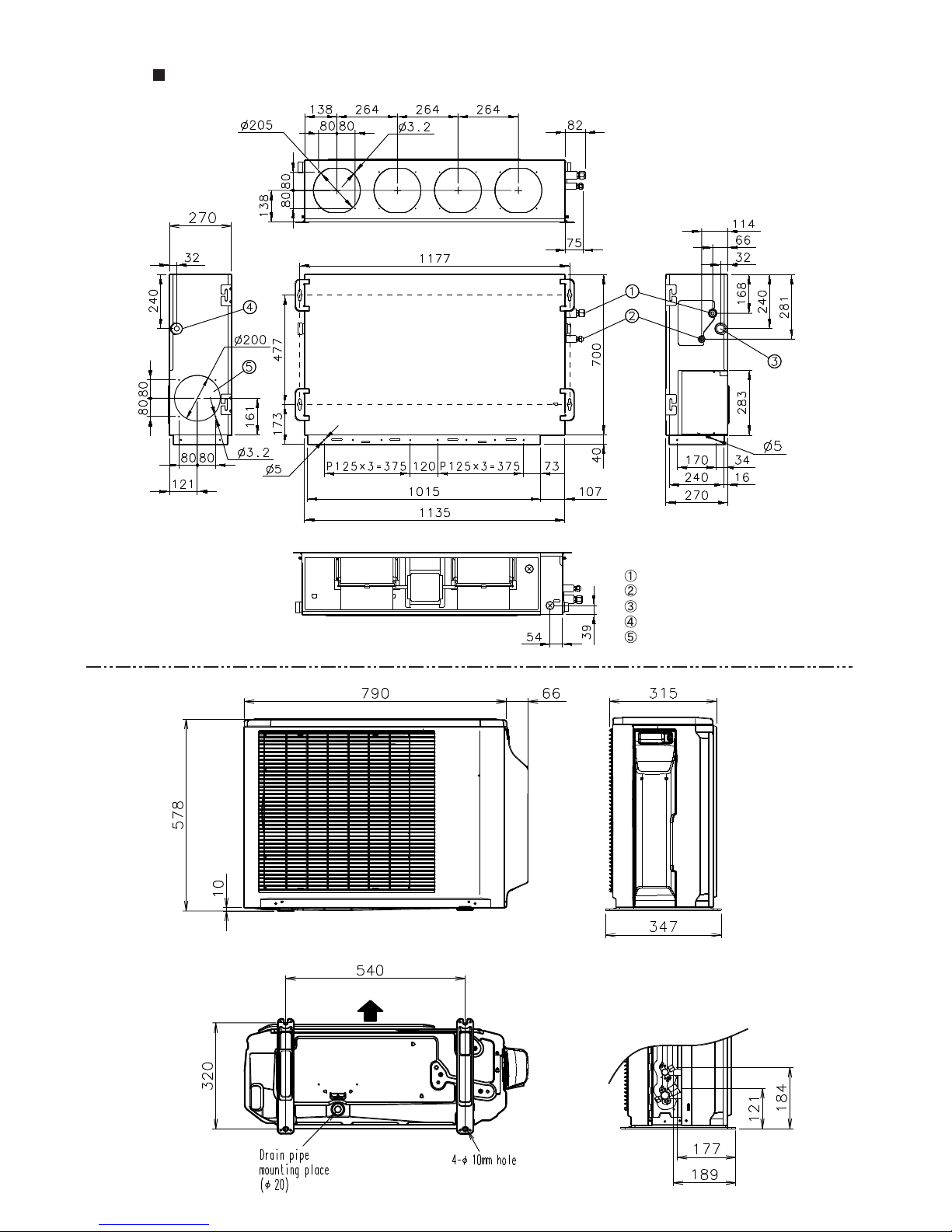
MODEL : AR*A24LATN / AO*A24LACL
Air flow
Front view
Side view
Bottom view
Refrigerant piping flare connection (Gas)
Refrigerant piping flare connection (Liquid)
Drain piping connection
Drain piping connection with cap.
Knock out hole for fresh air.
Front view
Top view
Side view (L)
Side view (R)
Rear view
Page 16

02-04
MODEL : AR*A36LATN / AO*A36LATL
AR*A45LATN / AO*A45LATL
(Unit : mm)
(Unit : mm)
Refrigerant piping flare connection (Gas)
Refrigerant piping flare connection (Liquid)
Drain piping connection
Drain piping connection with cap.
Knock out hole for fresh air.
Front view
Top view
Side view (L)
Side view (R)
Rear view
900
1290
77 31
21
370
9
400
650
151
99
196
170
4-Ø12mm hole
12330
Air flow
Drain cap mounting
places
Side view
Bottom view
Front view
Page 17

3 . REFRIGERANT SYSTEM DIAGRAM
R410A
DUCT type
INVERTER
Page 18

03-01
Ø9.52mm(3/8")
Ø6.35mm(1/4")
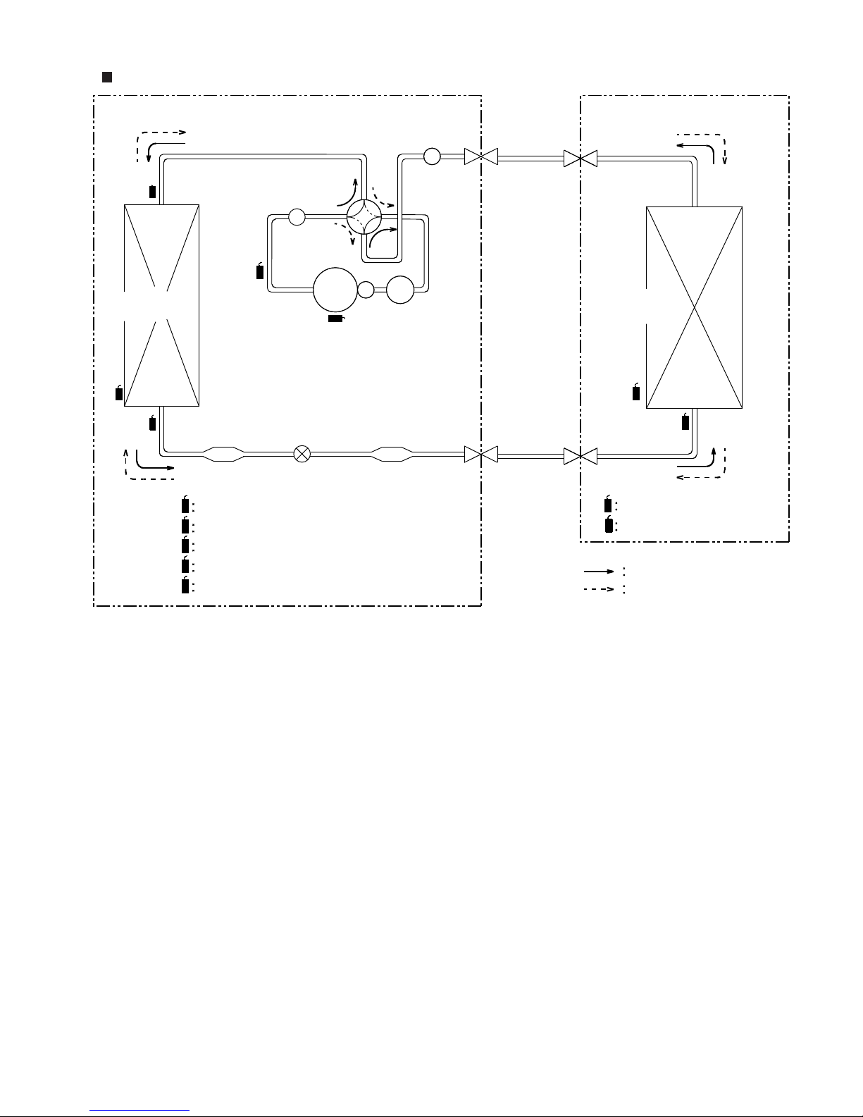
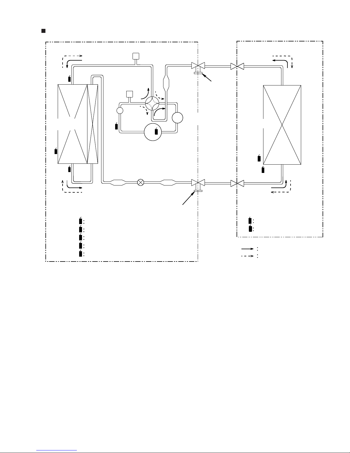
3. REFRIGERANT CIRCUIT
MODEL : AR*A12LATN / AO*A12LACL
Outdoor Unit Indoor Unit
CONDENSER EVAPOLATOR
THO
THHM
THHO
THD
THR
THR
THPI
THPI
THD
THC
THHO
THHM
COMPRESSOR
ACCUMULATOR
EXPANSION
VALVE
STRAINERSTRAINER
MUFFLER
MUFFLER
4-Way
valve
THERMISTOR(DISCHARGE TEMP.)
THC
THERMISTOR(COMPRESSOR TEMP.)
THERMISTOR(ROOM TEMP.)
THERMISTOR(PIPE TEMP.)
THERMISTOR(HEAT EXCHANGER MED TEMP.)
THO
THERMISTOR(OUTDOOR TEMP.)
THERMISTOR(HEAT EXCHANGER OUT TEMP.)
Refrigerant Pipe
Refrigerant Pipe
COOL
HEAT
3-way
VALVE
2-way
VALVE
Page 19

03-02
Ø12.7mm(1/2")
Ø6.35mm(1/4")
MODEL : AR*A14LATN / AO*A14LACL
AR*A18LATN / AO*A18LACL
Outdoor Unit Indoor Unit
CONDENSER EVAPOLATOR
THO
THHM
THHO
THD
THR
THR
THPI
THPI
THD
THC
THHO
THHM
COMPRESSOR
ACCUMULATOR
EXPANSION
VALVE
STRAINERSTRAINER
MUFFLER
MUFFLER
4-Way
valve
THERMISTOR(DISCHARGE TEMP.)
THC
THERMISTOR(COMPRESSOR TEMP.)
THERMISTOR(ROOM TEMP.)
THERMISTOR(PIPE TEMP.)
THERMISTOR(HEAT EXCHANGER MED TEMP.)
THO
THERMISTOR(OUTDOOR TEMP.)
THERMISTOR(HEAT EXCHANGER OUT TEMP.)
Refrigerant Pipe
Refrigerant Pipe
COOL
HEAT
3-way
VALVE
2-way
VALVE
Page 20
03-03
Ø15.88mm(5/8")
Ø6.35mm(1/4")
MODEL : AR*A24LATN / AO*A24LACL
Outdoor Unit Indoor Unit
CONDENSER EVAPOLATOR
THO
THHM
THHO
THD
THR
THR
THPI
THPI
THD
THC
THHO
THHM
COMPRESSOR
ACCUMULATOR
EXPANSION
VALVE
STRAINERSTRAINER
MUFFLER
MUFFLER
4-Way
valve
THERMISTOR(DISCHARGE TEMP.)
THC
THERMISTOR(COMPRESSOR TEMP.)
THERMISTOR(ROOM TEMP.)
THERMISTOR(PIPE TEMP.)
THERMISTOR(HEAT EXCHANGER MED TEMP.)
THO
THERMISTOR(OUTDOOR TEMP.)
THERMISTOR(HEAT EXCHANGER OUT TEMP.)
Refrigerant Pipe
Refrigerant Pipe
COOL
HEAT
3-way
VALVE
2-way
VALVE
Page 21
03-04
Ø15.88mm(5/8")
Ø9.52mm(3/8")
MODEL : AR*30/ 36LUAN / AO*30/ 36LMAWL
Outdoor Unit Indoor Unit
CONDENSER
HIGH PRESSURE
SWITCH
PRESSURE
CHECK VALVE
THO
THR
THR
THPI
THPI
THD
THC
THHO
COMPRESSOR
ACCUMULATOR
EXPANSION
VALVE
STRAINER
STRAINER
STRAINER
4-Way
valve
THERMISTOR(ROOM TEMP.)
THERMISTOR(PIPE TEMP.)
Refrigerant Pipe
Refrigerant Pipe
COOL
HEAT
THHM
EVAPOLATOR
Charging Valve
Charging Valve
MUFFLER
THHM
THHO
THD
THERMISTOR(DISCHARGE TEMP.)
THC
THERMISTOR(COMPRESSOR TEMP.)
THERMISTOR(HEAT EXCHANGER MED TEMP.)
THO
THERMISTOR(OUTDOOR TEMP.)
THERMISTOR(HEAT EXCHANGER OUT TEMP.)
Page 22

4 . CIRCUIT DIAGRAM
R410A
DUCT type
INVERTER
Page 23
04-01
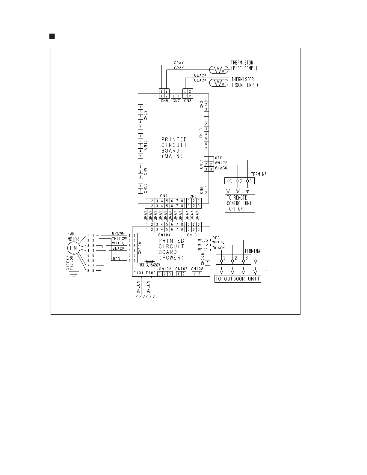
4. CIRCUIT DIAGRAM
MODEL : AR*A12/ 14/ 18LATN
Page 24

04-02
MODEL : AR*A24/ 36/ 45LATN
COIL
Page 25

04-03
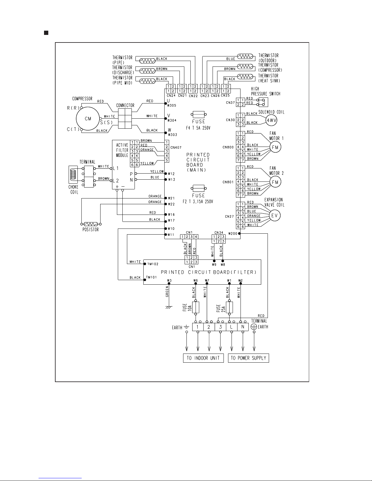
MODEL : AO*A12/ 14/ 18/ 24LACL
Page 26
04-04
MODEL : AO*A36/ 45LATL
Page 27

5 . DESCRIPTION OF EACH
CONTROL OPERATION
R410A
DUCT type
INVERTER
Page 28
5-1. COOLING OPERATION
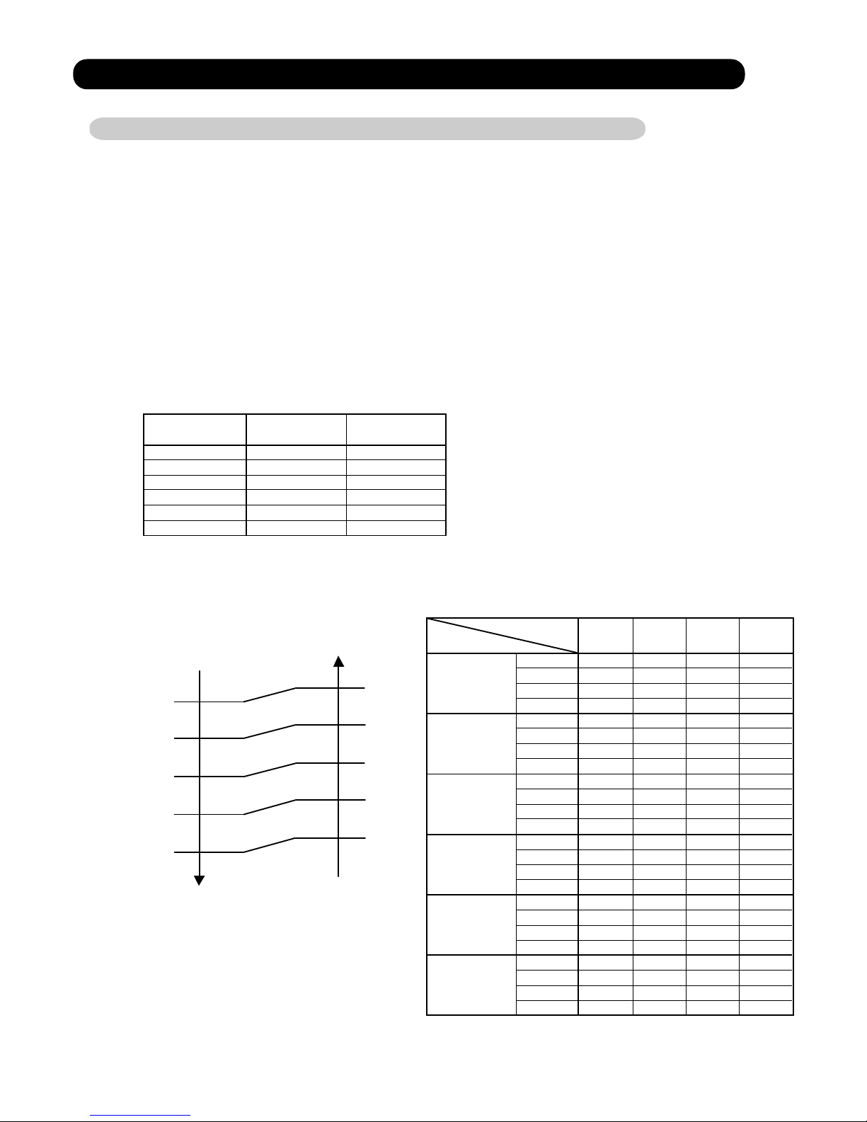
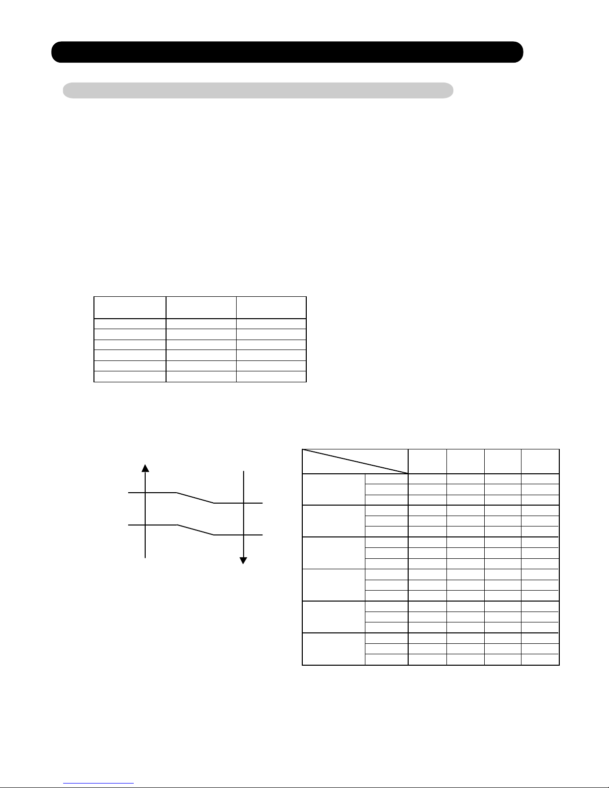
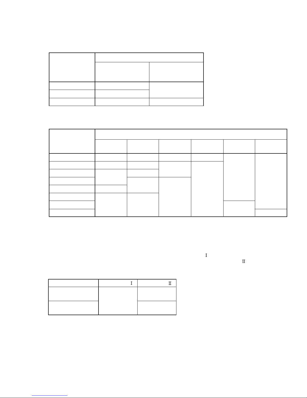
5-1-1 COOLING CAPACITY CONTROL
A sensor (room temperature thermistor) built in the indoor unit will usually perceive
difference or variation between a set temperature and present room temperature, and
controls the operation frequency of the compressor.
* If the room temperature is 2 degC higher than a set temperature,
the compressor operation frequency will attain to maximum performance.
* If the room temperature is 2.5 degC lower than a set temperature, the compressor will be stopped.
* When the room temperature is between +2 degC to -2.5 degC of the setting temperature,
the compressor frequency is controlled within the range shown in Table1.
However, the maximum frequency is limited in the range shown in Figure 1 based on the
fan speed mode and the outdoor temperature.
minimum
frequency
maximum
frequency
AR*A12LATN 18Hz
18Hz
18Hz
80Hz
113Hz
113Hz
AR*A14LATN
AR*A18LATN
AR*A24LATN 18Hz 113Hz
18Hz 77Hz
18Hz 70Hz
AR*A36LATN
AR*A45LATN
Outdoor air
temperature
A zone
B zone
C zone
D zone
E zone
F zone
Hi Me Lo Quiet
A zone 80Hz
80Hz
80Hz
49Hz
49Hz
49Hz
42Hz
42Hz
49Hz 42Hz
38Hz 30Hz
34Hz
34Hz
34Hz
22Hz
70Hz
70Hz
48Hz
37Hz
43Hz
43Hz
37Hz
37Hz
37Hz 33Hz
33Hz 29Hz
29Hz
29Hz
29Hz
23Hz
77Hz
77Hz
55Hz
41Hz
48Hz
48Hz
41Hz
41Hz
41Hz 37Hz
37Hz 33Hz
31Hz
31Hz
31Hz
25Hz
113Hz
113Hz
80Hz
54Hz
66Hz
66Hz
54Hz
54Hz
54Hz 45Hz
45Hz 38Hz
34Hz
34Hz
34Hz
24Hz
113Hz
113Hz
80Hz
54Hz
66Hz
66Hz
54Hz
54Hz
54Hz 45Hz
45Hz 38Hz
34Hz
34Hz
34Hz
24Hz
113Hz
113Hz
80Hz
54Hz
66Hz
66Hz
54Hz
54Hz
54Hz 45Hz
45Hz 38Hz
34Hz
34Hz
34Hz
24Hz
B zone
C zone
AR*A12LATN
D-F zone
A zone
B zone
C zone
AR*A14LATN
D-F zone
A zone
B zone
C zone
AR*A18LATN
AR*A24LATN
AR*A36LATN
AR*A45LATN
D-F zone
( Table 1 : Compressor Frequency Range )
( Fig. 1 : Limit of Maximum Frequency based on Outdoor Temperature )
05-01
A zone
B zone
C zone
D-F zone
A zone
B zone
C zone
D-F zone
A zone
B zone
C zone
D-F zone
Fan speed mode
When the room
temperature rises
When the room
temperature drops
36°C
32°C
21°C
12°C
2°C
34°C
30°C
19°C
10°C
0°C
Page 29
5-2. HEATING OPERATION
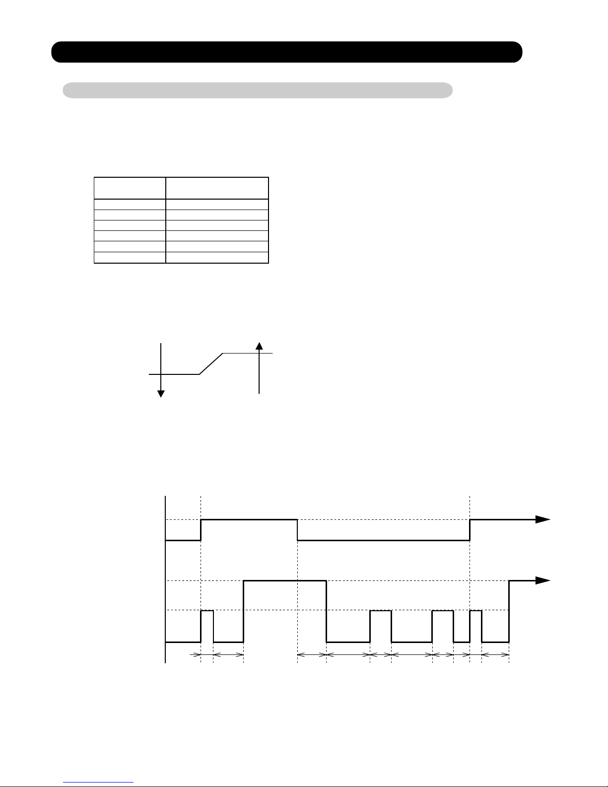
5-2-1 HEATING CAPACITY CONTROL
A sensor (room temperature thermistor) built in the indoor unit will usually perceive
difference or variation between a set temperature and present room temperature, and
controls the operation frequency of the compressor.
* If the room temperature is lower 3 degC than a set temperature,
the compressor operation frequency will attain to maximum performance.
* If the room temperature is higher 2.5 degC than a set temperature, the compressor
will be stopped.
* When the room temperature is between +2.5 degC to -3 degC of the setting temperature,
the compressor frequency is controlled within the range shown in Table2.
However, the maximum frequency is limited in the range shown in Figure 2 based on
the outdoor temperature.
( Table 2 : Compressor Frequency Range )
( Fig.2 : Limit of Maximum Frequency based on Outdoor Temperature )
05-02
Outdoor air
temperature
A zone
B zone
C zone
When the room
temperature rises
When the room
temperature drops
17°C
12°C
19°C
14°C
Hi
Me+
Me Lo Quiet
A zone 120Hz
120Hz
120Hz
70Hz
70Hz
60Hz
60Hz
70Hz 60Hz
49Hz
49Hz
49Hz
90Hz
90Hz
90Hz
66Hz
66Hz
53Hz
53Hz
66Hz 53Hz
45Hz
45Hz
45Hz
90Hz
90Hz
90Hz
66Hz
66Hz
53Hz
53Hz
66Hz 53Hz
45Hz
45Hz
45Hz
120Hz
120Hz
120Hz
101Hz
101Hz
75Hz
75Hz
101Hz 75Hz
60Hz
60Hz
60Hz
120Hz
120Hz
120Hz
101Hz
101Hz
75Hz
75Hz
101Hz 75Hz
60Hz
60Hz
60Hz
120Hz
120Hz
120Hz
101Hz
101Hz
75Hz
75Hz
101Hz 75Hz
60Hz
60Hz
60Hz
B zone
C zone
AR*A12LATN
A zone
B zone
C zone
AR*A14LATN
A zone
B zone
C zone
AR*A18LATN
AR*A24LATN
AR*A36LATN
AR*A45LATN
A zone
B zone
C zone
A zone
B zone
C zone
A zone
B zone
C zone
Fan speed mode
minimum
frequency
maximum
frequency
AR*A12LATN 18Hz
18Hz
18Hz
120Hz
120Hz
120Hz
AR*A14LATN
AR*A18LATN
AR*A24LATN 18Hz 120Hz
18Hz 90Hz
18Hz 90Hz
AR*A36LATN
AR*A45LATN
Page 30
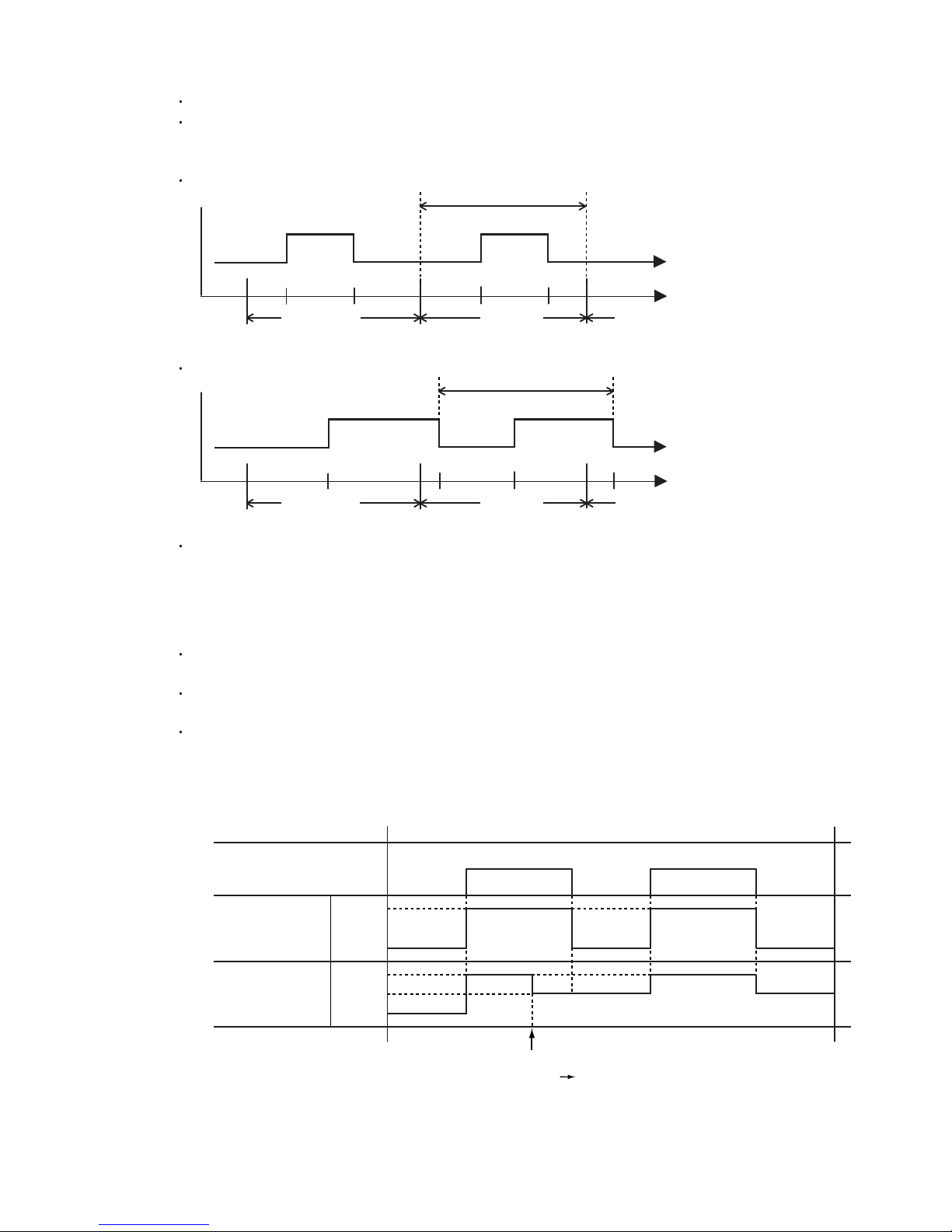
5-3. DRY OPERATION
5-3-1 INDOOR UNIT CONTROL
The compressor rotation frequency shall change according to set temperature and room
temperature variation which the room temperature sensor of the indoor unit has detected
as shown in the Fig 3.
Room
temperature
Room
temperature
Compressor ON
Ts+1.5 degC
Ts+0.5 degC
Compressor OFF
( Table 3 : Compressor frequency )
( Fig.3 : Compressor Control based on Room Temperature )
05-03
Operating frequency
Ts : Setting temperature
AR*A12LATN 34Hz
34Hz
34Hz
AR*A14LATN
AR*A18LATN
AR*A24LATN 34Hz
31Hz
31Hz
AR*A36LATN
AR*A45LATN
Compressor
ON
OFF
Indoor fan
Dry air flow
S-Lo
OFF
( Fig.4 : Indoor Fan Control )
10 30 60 180 60 180 60 10 30
(SEC)
Page 31
05-04
5-4. AUTO CHANGEOVER OPERATION
When the air conditioner is set to the AUTO mode by remote control, operation starts in the optimum
mode from among the HEATING, COOLING, DRY and MONITORING modes. During operation,
the optimum mode is automatically swiched in accordance with temperature changes.
The temperature can be set between 18°C and 30°C in 1 degC steps.
When operation starts, only the indoor and outdoor fans are operated for 1 minute.
After 1 minute, the room temperature and outdoor air temperature are sensed and
the operation mode is selected in accordance with the table below.
( Table 4 : Operation mode selection table )
[ For AR*A12/ 14/ 18/ 24LATN ]
1
Room temperature :Tb
Outdoor temperature :To
Tb > Ts +2 degC
Ts +2 degC > Tb
=
=
Ts +2 degC > Tb > Ts-2 degC
Cooling
(Automatic Dry)
Cooling
(Automatic Dry)
Monitoring
Monitoring Monitoring Monitoring
Monitoring
Heating Heating
Ts : Setting temperature
A zone B zone C zone
A zone
B zone
C zone
32°C
-10°C
[ For AR*A36/ 45LATN ]
A zone
B zone
C zone
32°C
-15°C
When COOLING was selected at , the air conditioner operates as follow:
The same operation as COOLING OPERATION of item 5-1 above is performed.
However, the setting temperature is raised 1degC and the room temperature correct coefficient value is 0°C
When the compressor frequency have been below 20Hz for 8 minutes or the room temperature reaches
"setting temperature -1.5°C" , operation is automatically switched to DRY OPERATION of item 5-3 above
is performed.
However, compressor control based on room temperature is as follows.
If the room temperature reaches "setting temperature +2°C" during DRY operation,
operation returns to COOLING operation.
When HEATING was selected at , the same operation as HEATING OPERATION of item 5-2
above is performed. However, the room temperature correct coefficient value is 0°C.
When the compressor was stopped for 6 consecutive minutes by the temperature control function
after the COOLING or HEATING operation mode was selected at above, operation is switched
to MONITORING and the operation mode is selected again.
1
2
3
1
4
1
( Fig.5 : Outdoor air temperature zone selection )
Room
temperature
Compressor :ON
Compressor :OFF
Ts -0.5°C
Ts -1.5°C
Page 32
5-5. INDOOR FAN CONTROL
1. Fan speed
( Table 5 : Indoor Fan Speed )
Operation mode Air flow mode
Speed (rpm)
Hi 880
780
720
620
Me
Lo
Dry
Monitoring
Quiet
620
450
Auto
S- Lo
2. FAN OPERATION
The airflow can be switched in 5 steps such as AUTO, QUIET, LOW, MED, HIGH,
while the indoor fan only runs.
When Fan mode is set at (Auto), it operates on [MED] Fan Speed.
Cooling
Heating
Fan
AR*A12LATN
Operation mode Air flow mode
Speed (rpm)
Hi 1040
950
840
740
Me
Lo
Dry
Monitoring
Quiet
740
450
Auto
S- Lo
Cooling
Heating
Fan
AR*A14LATN
Operation mode Air flow mode
Speed (rpm)
Hi 1040
950
840
740
Me
Lo
Dry
Monitoring
Quiet
740
450
Auto
S- Lo
Cooling
Heating
Fan
AR*A18LATN
Operation mode Air flow mode
Speed (rpm)
Hi 830
700
600
550
Me
Lo
Dry
Monitoring
Quiet
550
350
Auto
S- Lo
Cooling
Heating
Fan
AR*A24LATN
Operation mode Air flow mode
Speed (rpm)
Hi 1200
1020
840
670
Me
Lo
Dry
Monitoring
Quiet
Hi
Me
Lo
Quiet
1220
1020
840
670
670
370
Auto
S- Lo
Cooling
Heating
Fan
Heating
AR*A36LATN
Operation mode Air flow mode
Speed (rpm)
Hi 1310
1020
840
670
Me
Lo
Dry
Monitoring
Quiet
Hi
Me
Lo
Quiet
1300
1020
840
670
670
370
Auto
S- Lo
Cooling
Heating
Fan
Heating
AR*A45LATN
05-05
Page 33

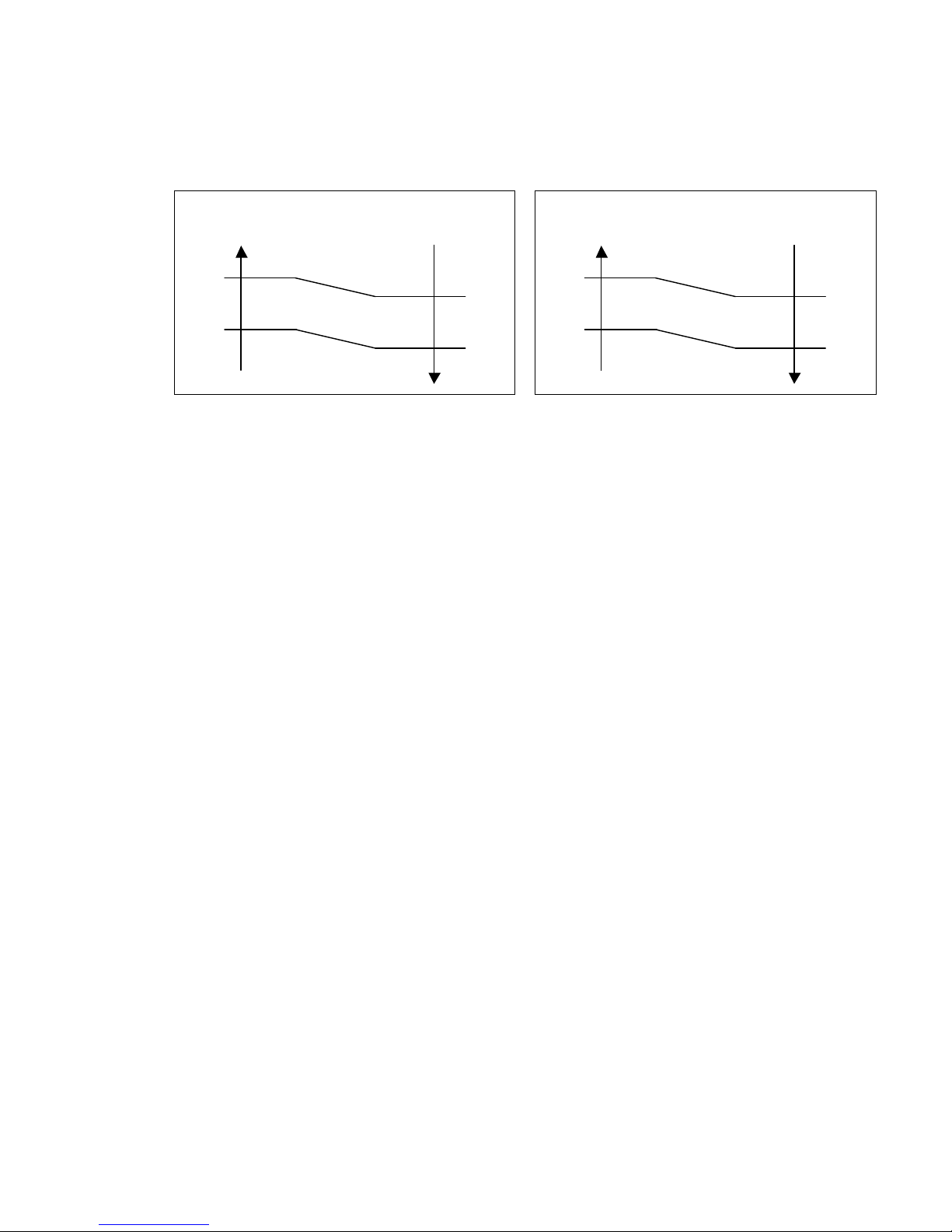
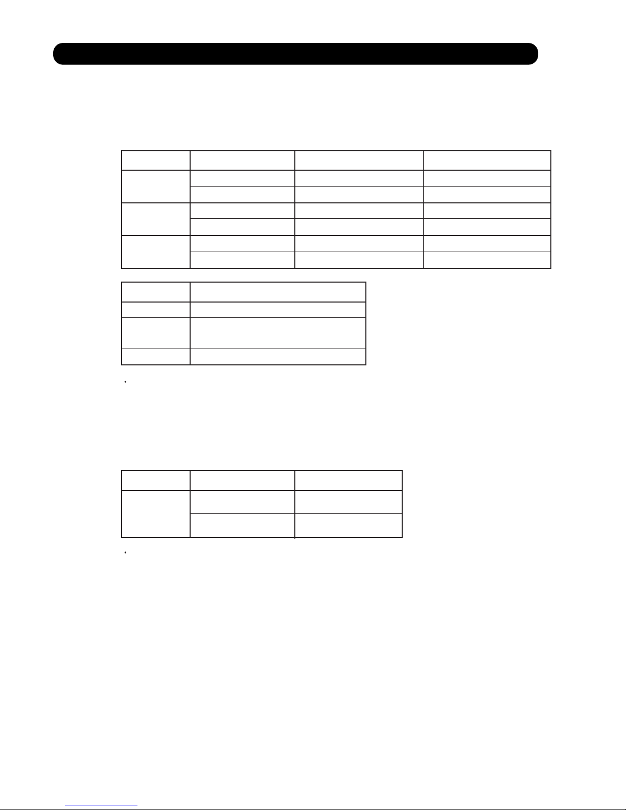
4. HEATING OPERATION
05-06
3. COOLING OPERATION
( Fig.6 : Airflow change - over ( Cooling : AUTO ) )
When the room
temperature rises
When the room
temperature drops
TR : Room temperature
Ts : Setting temperature
TR-Ts > - 1.5 degC
=
- 2.5 degC > TR-Ts
- 1.5 degC > TR-Ts > - 2.5 degC
=
TR-Ts > 2 degC
=
1 degC > TR-Ts
2 degC > TR-Ts > 1 degC
=
TR-Ts > 2.5 degC
=
1.5 degC > TR-Ts
2.5 degC > TR-Ts > 1.5 degC
=
TR-Ts > - 1 degC
=
- 2 degC > TR-Ts
- 1 degC > TR-Ts > - 2 degC
=
HIGH mode
MED mode
LOW mode
( Fig.7 : Airflow change - over ( Heating : AUTO ) )
When the room
temperature rises
When the room
temperature drops
TR : Room temperature
Ts : Setting temperature
LOW mode
MED mode
HIGH mode
Switch the airflow [AUTO], and the indoor fan motor will run according to a room temperature,
as shown in Figure 6.
On the other hand, if switched in [HIGH] [QUIET], the indoor motor will run at a constant airflow of [COOL]
operation modes QUIET, LOW, MED, HIGH, as shown in Table 5.
Switch the airflow [AUTO], and the indoor fan motor will run according to a room temperature,
as shown in Figure 7.
On the other hand, if switched [HIGH] [QUIET], the indoor motor will run at a constant airflow of [HEAT]
operation modes QUIET, LOW, MED, HIGH, as shown in Table 5.
Page 34
5. COOL AIR PREVENTION CONTROL (Heating mode)
6. DRY OPERATION
Refer to the Figure 4.
During the dry mode operation, the fan speed setting can not be changed.
05-07
SETTING
FAN MODE
LOW mode
S-LOW mode
37°C
30°C
32°C
24°C
Indoor heat exchanger
temperature
Indoor heat exchanger
temperature
HIGH mode
LOW mode
S-LOW mode
37°C
30°C
32°C
24°C
Indoor heat exchanger
temperature
Indoor heat exchanger
temperature
The maximum value of the indoor fan speed is set as shown in Figure 8, based on the detected
temperature by the indoor heat exchanger sensor on heating mode.
( Fig.8 : Cool Air Prevention Control )
(1) Fan mode : HIGH (2) Fan mode : MED, LOW, QUIET
Page 35
5-6. OUTDOOR FAN CONTROL
1. Outdoor Fan Motor
1-1. For AR*A12/ 14/ 18/ 24LATN
Following table shows the fan speed of the outdoor unit.
05-08
Table 6 : Fan speed of the outdoor unit
Table 7 : Fan speed when starting up outdoor fan
Outdoor temperature
The outdoor fan speed is changed in the range of the speed shown in the above table,
based on the frequency of the compressor.
(When the compressor frequency increases, the outdoor fan speed is also changed to
higher speed. If the compressor frequency decreases, the outdoor fan speed is changed
to the lower speed as well.)
After starting up the outdoor fan, it operates with the following speed for initial 20 seconds.
After operating the defrost control function on heating mode except economy operation,
its speed becomes 950rpm (AR*A12/14/18L) and 1050rpm (AR*A24L)
regardless of the compressor frequency.
However, it returns to the normal speed control when the defrosting operation does not function
for 240 minutes after releasing the defrost operation or when the outdoor temperature sensor
detection value becomes higher than 5°C.
Over than 12°C
Less than 12°C
Over than 12°C
Less than 12°C
Over than 12°C
Less than 12°C
Cooling
860/ 820/ 770/ 670/ 500 rpm
400/ 340/ 280/ 250/ 230 rpm
Dry
500 rpm
400/ 340/ 280/ 250/ 230 rpm
860/ 820/ 670/ 500 rpm
400/ 340/ 280/ 250/ 230 rpm
500 rpm
400/ 340/ 280/ 250/ 230 rpm
950/ 820/ 670/ 500 rpm
400/ 340/ 280/ 250/ 230 rpm
500 rpm
400/ 340/ 280/ 250/ 230 rpm
AR*A12LATN
AR*A14LATN
AR*A18LATN
AR*A24LATN
Outdoor temperature
Over than 12°C
Less than 12°C
Fan speed
500 rpm
200 rpm
AR*A12LATN
AR*A14LATN
AR*A18LATN
AR*A24LATN
Heating
950/ 820/ 750/ 700/ 550/ 450 rpm
950/ 820/ 750/ 670/ 550/ 450 rpm
1050/ 1000/ 730/ 670/ 550/ 450 rpm
AR*A12LATN
AR*A14LATN
AR*A18LATN
AR*A24LATN
Page 36
1-2. For AR*A36/ 45LATN
Following table shows the fan speed of the outdoor unit.
The outdoor fan speed changs in the range mentioned avobe depending on the compressor
frequency and outdoor temperature.
It runs at 500rpm for 20 seconds after starting up the outdoor fan.
When the outdoor heat exchanger temperature is lower than 2°C,
the fan speed switches to 850rpm(Upper fan) and 750rpm(Lower fan) on heating mode.
05-09
Table 8 : Fan speed of the outdoor unit
AR*A36/ 45LATN have two fan motors.
Cooling
Heating
Upper fan
Lower fan
850/ 780/ 520/ 400/ 350/ 300/ 280 rpm 850/ 780/ 350/ 200/ 170/ 150 rpm
780/ 750/ 350/ 200/ 170/ 150 rpm
780/ 750/ 520/ 350/ 280/ 0 rpm
AR*A36LATN
AR*A45LATN
Page 37

5-7. COMPRESSOR CONTROL
1. OPERATION FREQUENCY RANGE
The operation frequency of the compressor is different based on the operation mode as
shown in Table 9.
Cooling Heating
Min Max Min Max
Dry
(Table 9 : Compressor Operation Frequency Range)
2. OPERATION FREQUENCY CONTROL AT START UP
2-1. For AR*A12/ 14/ 18/ 24LATN
The compressor frequency soon after the start-up is controlled as shown in Figure 9.
(Fig.9 : Compressor Control at Start-up)
40Hz
90sec 180sec 270sec
59Hz
05-10
AR*A12LATN
18Hz
80Hz
18Hz
120Hz
34Hz
AR*A14LATN
18Hz
113Hz
18Hz
120Hz
34Hz
AR*A18LATN
18Hz
113Hz
18Hz
120Hz
34Hz
AR*A24LATN
18Hz
113Hz
18Hz
120Hz
34Hz
18Hz
77Hz
18Hz
90Hz
31Hz
18Hz
70Hz
18Hz
90Hz
31Hz
AR*A36LATN
AR*A45LATN
85Hz
2-2. For AR*A36/ 45LATN
The compressor frequency soon after the start-up is controlled as shown in Figure 10.
(Fig.10 : Compressor Control at Start-up)
28Hz
90sec 180sec 270sec
43Hz
54Hz
70Hz
360sec
Page 38
05-11
AR-6TC1
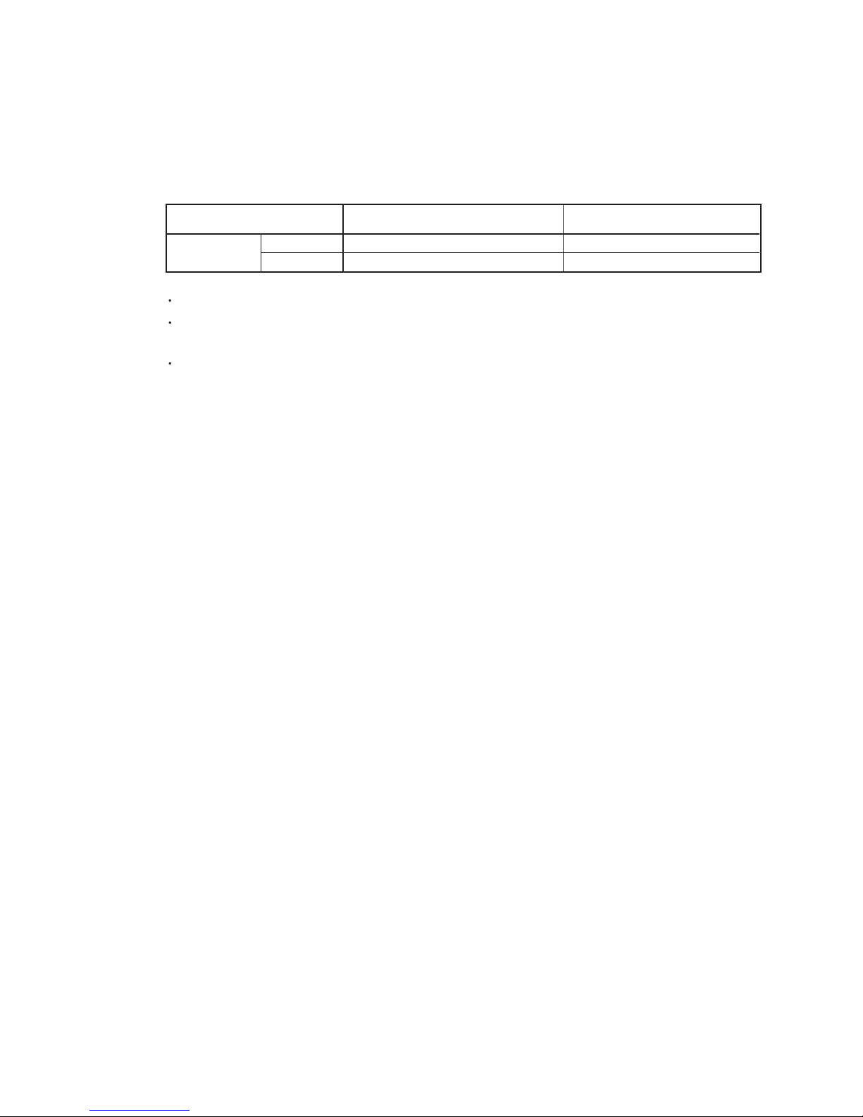
1. ON / OFF TIMER
OFF timer : When the clock reaches the set time, the air conditioner will be turned off.
Operation mode
Stop mode
Set time of timer
ON timer : When the clock reaches the set time, the air conditioner will be turned on.
Operation mode
Stop mode
Set time of timer
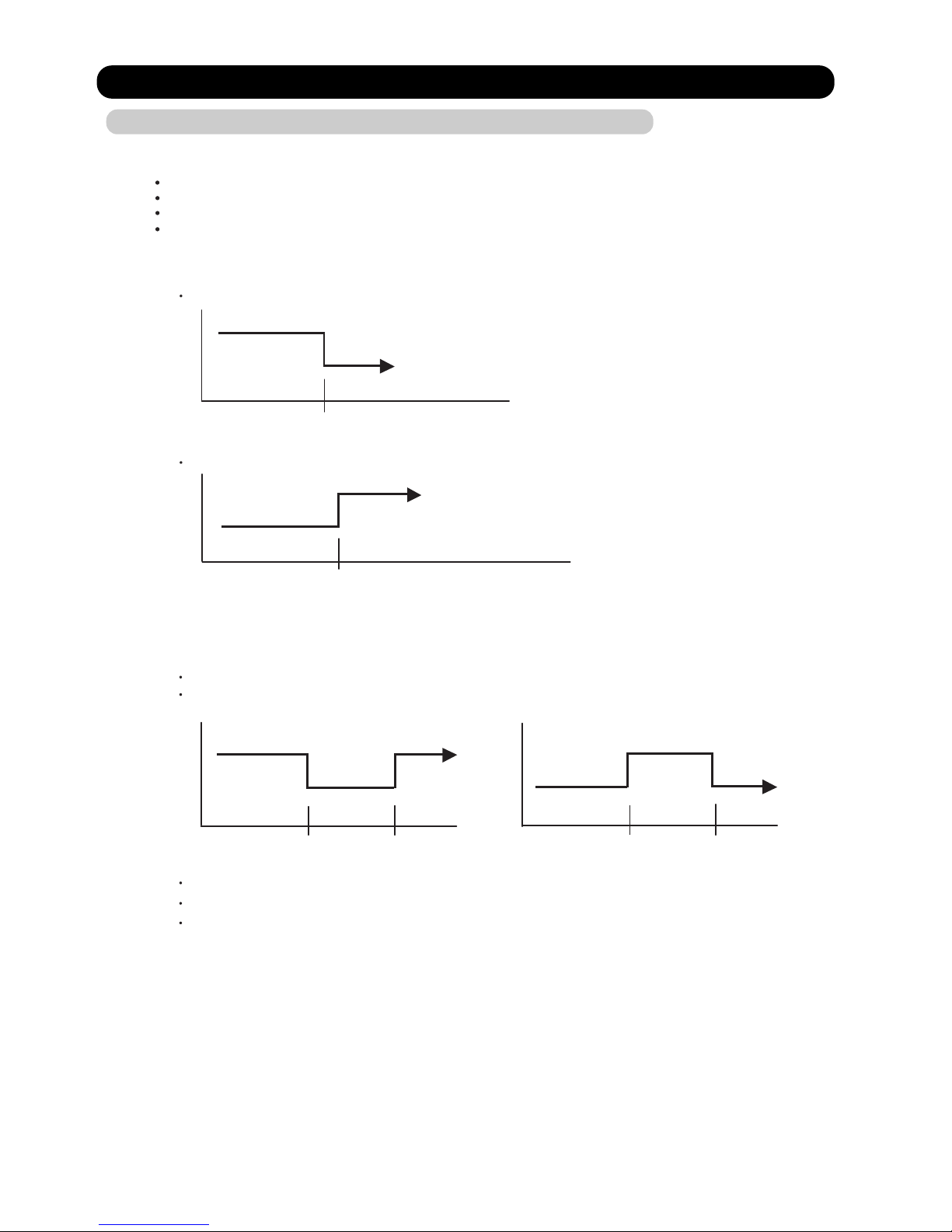
The weekly timer allows up to two ON and OFF time to set up per day.
Use this timer function to set operating time for each day of the week.
Operation mode
The operating time can be set in 30 min increments only.
The OFF time can be carried over to next day.
The ON timer and the OFF timer functions cannot be set with using the weekly timer.
Both ON and OFF time must be set.
2. WEEKLY TIMER
2-1. WEEKLY TIMER
Stop mode
Stop mode
Stop mode
Operation mode
Operation mode
Set time
Set time Set time Set time
5-8-1 Wired Remote Controller
ON / TIMER
OFF / TIMER
WEEKLY TIMER
TEMPERATURE SET BACK TIMER
5-8. TIMER OPERATION CONTROL
Page 39
05-12
The DAY OFF setting is only available for days for which weekly settings already exist.
The SET BACK timer only changes the set temperature for 7 days, it cannot be used to start or stop
air conditioner operation.
The SET BACK timer can be set to operate up to two times per day but only one temperature setting
can be used.
During the COOL/DRY mode, the air conditioner will operate at a minimum of 18°C even if
the SET BACK temperature is set to 17°C or lower.
The DAY OFF setting can only be set one time. The DAY OFF setting is cancelled automatically
after the set day has passed.
Normal
Next day setting
If the operating time carries over to the next day (during a next day setting), the effective
DAY OFF range will be set as shown below.
2-2. DAY OFF setting
3. TEMPERATURE SET BACK TIMER
Stop mode
Stop mode
Operation mode
Stop mode
Operation mode
Preceding day Next day
DAY OFF
Stop mode
Stop mode
Operation mode
Stop mode
Operation mode
DAY OFF
Setting day
Preceding day Next daySetting day
Case of SET BACK timer on the Cooling operation.
( Setting temperature :22°C, SET BACK temperature :26°C)
SET BACK setting
Operation
temperature
Operation
temperature
26°C
22°C
26°C
22°C
24°C
*1
ON OFF OFFON
*1: During the SET BACK function,
the setting temperature is changed.
Chenge the setting temperature:
22°C 24°C
Page 40

5-9. ELECTRONIC EXPANSION VALVE CONTROL
5-10. TEST OPERATION CONTROL
Under the condition where the air conditioner stops, press the MASTER CONTROL button and
the FAN CONTROL button simultaneously for 2 seconds or more, and the test operation control
mode will appear.
During test running, " " will display on the remote controller display.
Set the test operation mode, and the compressor will continue to run regardless of whatever
the room temperature sensor detects.
The test operation mode is released if 60 minutes have passed after setting up the test operation.
The compressor won't enter operation status for 3 minutes after the compressor is stopped,
even if any operation is given.
5-11. PREVENT TO RESTART FOR 3 MINUTES ( 3 MINUTES ST )
05-13
The most proper opening of the electronic expansion valve is calculated and controlled under the
present operating condition based on the following values.
The compressor frequency, the temperatures detected by the discharge temperature sensor, the
indoor heat exchanger sensor, the outdoor heat exchanger sensor, and the outdoor temperature
sensor.
Pulse range
60 480 pulse
(1) Pulse range of EEV
(2) The EEV is set up at 480 pulses when the compressor is stopped.
(3) Intialization (Input of 528 pulses toward closing direction) is operated under
the following condition.
* When the power is turned on.
* 4 hours has passed since the last initialization, and 3 minutes has passed after
the compressor stop.
(If 12 hours has passed since the last initialization, the compressor is compulsorily stopped.)
AR*A12LATN
AR*A14LATN
AR*A18LATN
AR*A24LATN
AR*A36LATN
AR*A45LATN
Cooling/ Dry
Cooling/ Dry
Heating
Heating
Operation
50 480 pulse
62 480 pulse
Page 41

At the time when the air conditioner is switched from the cooling mode to heating mode,
the compressor is stopped, and the 4-way valve is switched in 3 minutes later
after the compressor stopped.
When the power was interrupted by a power failure, etc. during operation, the operation contents
at that time are memorized and when power is recovered, operation is automatically resumed with
the memorized operation contents.
When the power is interrupted and recovered during timer operation, timer operation is canceled,
but only setting time is memorized.
[Operation contents memorized when the power is interrupted]
Operation mode
Set temperature
Set air flow
Timer mode and timer time
Thermistor detected position (When using the Wired Remote Controller)
5-12. 4-WAY VALVE EXTENSION SELECT
5-13. AUTO RESTART
05-14
5-14. PUMP DOWN ( For AR*A36/ 45LATN )
1. Press the PUMP DOWN switch (SW2) on the outdoor unit.
(The LED on the outdoor unit circuit board starts flashing (1sec.ON / 1sec.OFF repeated).)
2. The pump down operation (cooling operation) begins right away.
After operation starts, close the 3-way valve (liquid).
3. After 2-3minutes, operation stops. Close the 3-way valve (gas) within 1minute after operations stops.
4. The LED will go out 3minutes after it stops. Disconnect the power supply after confirming that
the LED has gone out.
1. Press the PUMP DOWN switch (SW2) on the outdoor unit. The LED on the outdoor unit circuit board starts
flashing (1sec.ON / 1sec.OFF repeated), and operation stops.
At this point, recovery has not been completed, so do not close the 3-way valves (liquid and gas).
2. The pump down operation (cooling operation) begins after 3minutes.
Close the 3-way valve (liquid) after operation starts.
3. After 2-3minutes, operation stops. Close the 3-way valve (gas) within 1minute after operations stops.
4. The LED will go out 3minutes after it stops. Disconnect the power supply after confirming that
the LED has gone out.
Perform the following procedures to collect the refrigerant when moving the indoor unit or the outdoor unit.
When the product is operating:
When the product is stopped:
5-15. COMPRESSOR PREHEATING
When the outdoor heat exchanger temperature is lower than 5°C and the heating operation
has been stopped for 30 minutes, power is applied to the compressor and the compressor is heated.
(By heating the compressor, warm air is quickly discharged when operation is started.)
When operation was started, and when the outdoor temperature rises to 7°C or greater,
preheating is ended.
Page 42
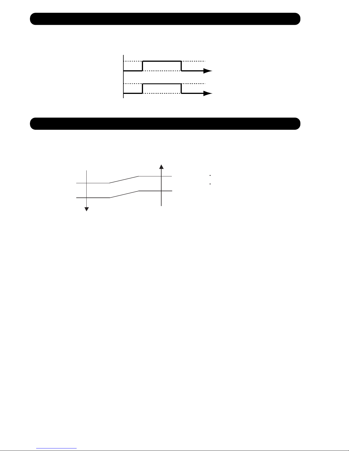
The fan motor for Fresh Air is operated in synchronization with the indoor fan operation
as shown in Figure 11.
The external electrical heater is operated as shown in Figure 12.
5-16. FRESH AIR CONTROL
5-17. EXTERNAL ELECTRICAL HEATER CONTROL
05-15
(Fig.11 : Fresh air control)
(Fig.12 : External electrical heater control)
Operation
Stop
Operation
Stop
Fan motor
(Indoor unit)
Fan motor
(for Fresh Air)
When the room
temperature rises
When the room
temperature drops
Ts : Setting temperature
Heater : OFF
Heater : ON
Heater : OFF
Ts -10°C
Ts -1°C
Ts -3°C
Ts -12°C
When the compressor stop,
External electrical heater is OFF.
Page 43
05-16
2. CONDITION OF THE DEFROST OPERATION COMPLETION
Release Condition
Outdoor heat exchanger temperature sensor value is higher than +10°C or
Compressor operation time has passed 15 minutes.
5-18. DEFROST OPERATION CONTROL
1. CONDITION OF STARTING THE DEFROST OPERATION
The defrost operation starts when the outdoor heat exchanger temperature sensor detects
the temperature lower than the values shown in Table 11.
(Table 11 : Condition of starting Defrost Operation)
1st time defrosting after starting operation
Less than 17 min.
17 to 62 min.
62 min. to 4 hours
After 4 hours
Does not operate
- 9°C
- 5°C
- 3°C
Compressor integrating
operation time
Compressor contiguous
operation time
Defrost operation is released when the conditions become as shown in Table 12.
(Table 12 : Defrost Release Condition)
Operation
temperature
Below 10 min.
Above 10 min.
Less than 35 min.
35 min. to 4 hours
After 4 hours
Does not operate
- 6°C
- 3°C
Compressor integrating
operation time
Compressor contiguous
operation time
Operation
temperature
Below 10 min.
Above 10 min.
Defrosting after 2nd time upon starting operation
Page 44

(Not defrosted for 10 minutes)
Outdoor fan : Lo
Compressor frequency : 20 Hz
EEV : 480pulse
4-way valve : OFF
Outdoor fan : OFF
Compressor frequency : 70Hz
Heating operation start : Compressor ON
Defrost Indicator:
[Operation lamp]
7 sec ON / 2 sec OFF
Outdoor heat exchanger temperature: Over 10°C
or
Compressor ON time: Over 15 minutes
Defrost end
05-17
Defrost start
3. Defrost Flow Chart
The defrosting shall proceed by the integrating operation time
and outdoor heat exchanger emperature as follows.
Compressor integrating
operation:
Over 17 minutes to
below 62 minutes
Compressor integrating
operation:
Over 240 minutes
Compressor integrating
operation:
Over 62 minutes to
below 240 minutes
Outdoor
heat exchanger
temperature:
Below - 9°C
Outdoor
heat exchanger
temperature:
Below - 5°C
Compressor integrating
operation:
Over 35 minutes to
below 240 minutes
Outdoor
heat exchanger
temperature:
Below - 6°C
Compressor integrating
operation:
Over 240 minutes
Outdoor
heat exchanger
temperature:
Below - 3°C
Outdoor
heat exchanger
temperature:
Below - 3°C
(In case of 1st defrost)
(In case of 2nd and later defrost)
Outdoor fan : OFF
Compressor : OFF
EEV : 480pulse
4-way valve : OFF
Compressor : ON
(Frequency : 70Hz)
AR*A12/ 14/ 18/ 24LATN AR*A36/ 45LATN
Outdoor temp Outdoor heat exchanger
temperature:
Above 5 degC
Page 45
05-18
Release Condition
Outdoor heat exchanger temperature sensor value is higher than +10°C or
Compressor operation time has passed 15 minutes.
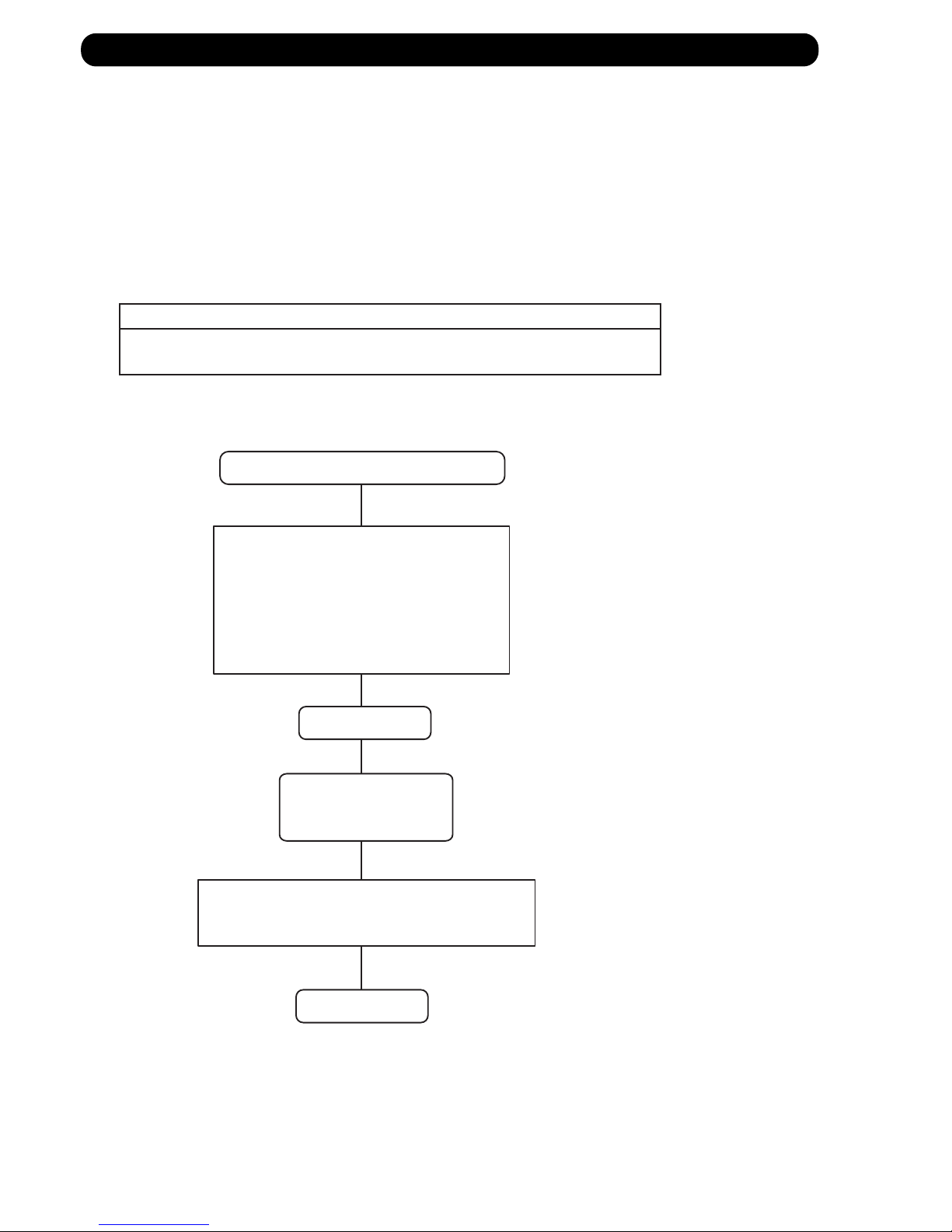
5-19. OFF DEFROST OPERATION CONTROL
1. OFF DEFROST OPERATION CONDITION
When operation stops in the [Heating operation] mode, if frost is adhered to the outdoor unit
heat exchanger, the defrost operation will proceed automatically.
In this time, if indoor unit operation lamp flashes slowly (7 sec ON / 2 sec OFF),
the outdoor unit will allow the heat exchanger to defrost, and then stop.
In heating operation, the outdoor heat exchanger temperature is less than - 4 C,
and compressor operation integrating time lasts for more than 30 minutes.
and compressor operation contiguous time lasts for more than 10 minutes.
OFF Defrost Flow Chart
Heating operation stop
2. OFF DEFROST END CONDITION
Outdoor heat exchanger temperature: Over 10°C
or
Compressor ON time: Over 15 minutes
Outdoor heat exchanger temperature:
Below - 4°C
and
Compressor integrating operation:
Over 30 minutes
and
Compressor contiguous operation:
Over 10 minutes
Defrost start
Defrost Indicator:
[Operation lamp]
7 sec ON / 2 sec OFF
Defrost end
Page 46

05-19
5-20. ECONOMY OPERATION
At the maximum output, ECONOMY OPERATION is approximately 70% of normal air conditioner operation
for cooling and heating.
When ECONOMY OPERATION is performed during the cooling mode,dehumidification is improved.
This function is especially convenient when you want to remove the humidity in the room
without significantly lowering the room temperature.
During ECONOMY OPERATION, the thermostat setting automatically changes according to the temperature
to avoid Unnecessary cooling and heating for the most economical operation.
If the room is not cooled (or heated) well during economy operation, select normal operation.
During the monitor period in the AUTO mode, the air conditioner operation will not change
to ECONOMY OPERATION even if ECONOMY OPERATION is selected by pressing the ECONOMY button.
Page 47

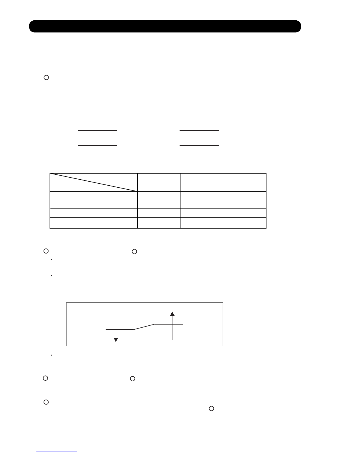
5-21. VARIOUS PROTECTIONS
1. DISCHARGE GAS TEMPERATURE OVER RISE PREVENTION CONTROL
The discharge gas thermosensor (discharge thermistor : Outdoor side) will detect discharge gas
temperature.
When the discharge temperature becomes higher than 104°C, the compressor frequency
is decreased 20 Hz, and it continues to decrease the frequency for 20 Hz every 120 seconds until
the temperature becomes lower than 101°C.
When the discharge temperature becomes lower than 101°C, the control of the compressor
frequency is released.
When the discharge temperature becomes higher than 110°C, the compressor stops
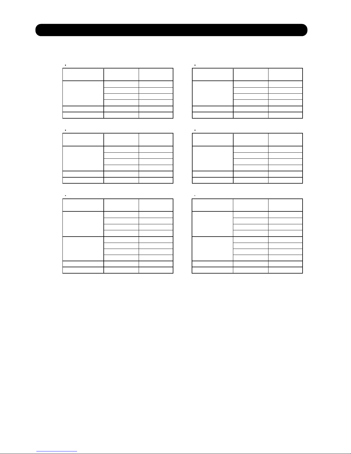
2. CURRENT RELEASE CONTROL
2-1. For AR*A12/ 14/ 18/ 24LATN
05-20
1-1. For AR*A12/ 14/ 18/ 24LATN
The discharge gas thermosensor (discharge thermistor : Outdoor side) will detect discharge gas
temperature.
When the discharge temperature becomes higher than 105°C, the compressor frequency
is decreased 10 Hz, and it continues to decrease the frequency for 10 Hz every 120 seconds until
the temperature becomes lower than 105°C.
When the discharge temperature becomes lower than 100°C, the control of the compressor
frequency is released.
When the discharge temperature becomes higher than 115°C, the compressor stops
1-2. For AR*A36/ 45LATN
OT (Control / Release)
6.5A/ 6.0A
8.0A/ 7.5A
8.5A/ 8.0A
9.5A/ 9.0A
17°C
12°C
The compressor frequency is controlled so that the outdoor unit input current does not exceeds
the current limit velue that was set up with the outdoor temperature.
The compressor frequency returns to the designated frequency of the indoor unit at the time
when the frequency becomes lower than the release value.
(Table 13 : Current Release Operation Value / Release Value)
[ Heating ]
OT : Outdoor Temperature
5°C
AR*A12LATN
OT (Control / Release)
7.0A/ 6.5A
9.0A/ 8.5A
10.5A/ 10.0A
12.0A/ 11.5A
17°C
12°C
OT : Outdoor Temperature
5°C
AR*A14/ 18LATN
OT (Control / Release)
7.0A/ 6.5A
9.0A/ 8.5A
11.5A/ 11.0A
13.0A/ 12.5A
17°C
12°C
OT : Outdoor Temperature
5°C
AR*A24LATN
OT (Control / Release)
4.5A/ 4.0A
6.0A/ 5.5A
7.0A/ 6.5A
46°C
40°C
[ Cooling ]
OT : Outdoor Temperature
AR*A12LATN
OT (Control / Release)
4.5A/ 4.0A
6.0A/ 5.5A
8.5A/ 8.0A
46°C
40°C
OT : Outdoor Temperature
AR*A14/ 18LATN
OT (Control / Release)
7.0A/ 6.5A
9.5A/ 9.0A
11.5A/ 11.0A
46°C
40°C
OT : Outdoor Temperature
AR*A24LATN
Page 48
05-21
[ Heating ]
T0 > 20°C
T0 < 12°C
=
T0: Outdoor temperature
850/ 780 rpm
780/ 780 rpm
350/ 350 rpm
850/ 750 rpm
780/ 780 rpm
280/ 280 rpm
400/ 0 rpm
520/ 520 rpm 350/ 350 rpm 300/ 0 rpm350/ 0 rpm
200/ 200 rpm
170/ 170 rpm
150/ 150 rpm
13.0A / 12.5A13.0A / 12.5A
15.0A / 14.5A
18.0A / 17.5A
15.0A / 14.5A
Outdoor unit fan speed (UP / LO)
[ Cooling ]
T0 > 46°C
=
T0: Outdoor temperature
11.0A / 10.5A 11.0A / 10.5A 11.0A / 10.5A 11.0A / 10.5A 11.0A / 10.5A 11.0A / 10.5A
11.5A / 11.0A
12.0A / 11.5A
12.0A / 11.5A 12.0A / 11.5A
14.0A / 13.5A
14.5A / 14.0A 14.5A / 14.0A
15.0A / 14.5A
17.5A / 17.0A
18.0A / 17.5A
17.5A / 17.0A
14.0A / 13.5A 14.0A / 13.5A
Outdoor unit fan speed (UP / LO)
T0 < 0°C
46°C > T0 > 40°C
=
20°C > T0 > 12°C
=
40°C > T0 > 31°C
=
31°C > T0 > 25°C
=
25°C > T0 > 13°C
=
13°C > T0 > 7°C
=
7°C > T0 > 0°C
=
2-2. For AR*A36/ 45LATN
(Table 13-2 : Current Release Operation Value / Release Value)
3. ANTIFREEZING CONTROL (Cooling and Dry mode)
The compressor frequency is decrease on cooling & dry mode when the indoor heat exchanger
temperature sensor detects the temperature lower than Temperature .
Then, the anti-freezing control is released when it becomes higher than Temperature .
(Table 14 : Anti-freezing Protection Operation / Release Temperature)
Outdoor temperature
Over than 10°C *1
or 12°C *2
Less than 10°C *1
or 12°C *2
*1. When the temperature rises.
*2. When the temperature drops.
4°C
7°C
13°C
Temperature Temperature
Page 49

Indoor heat exchange
temperature
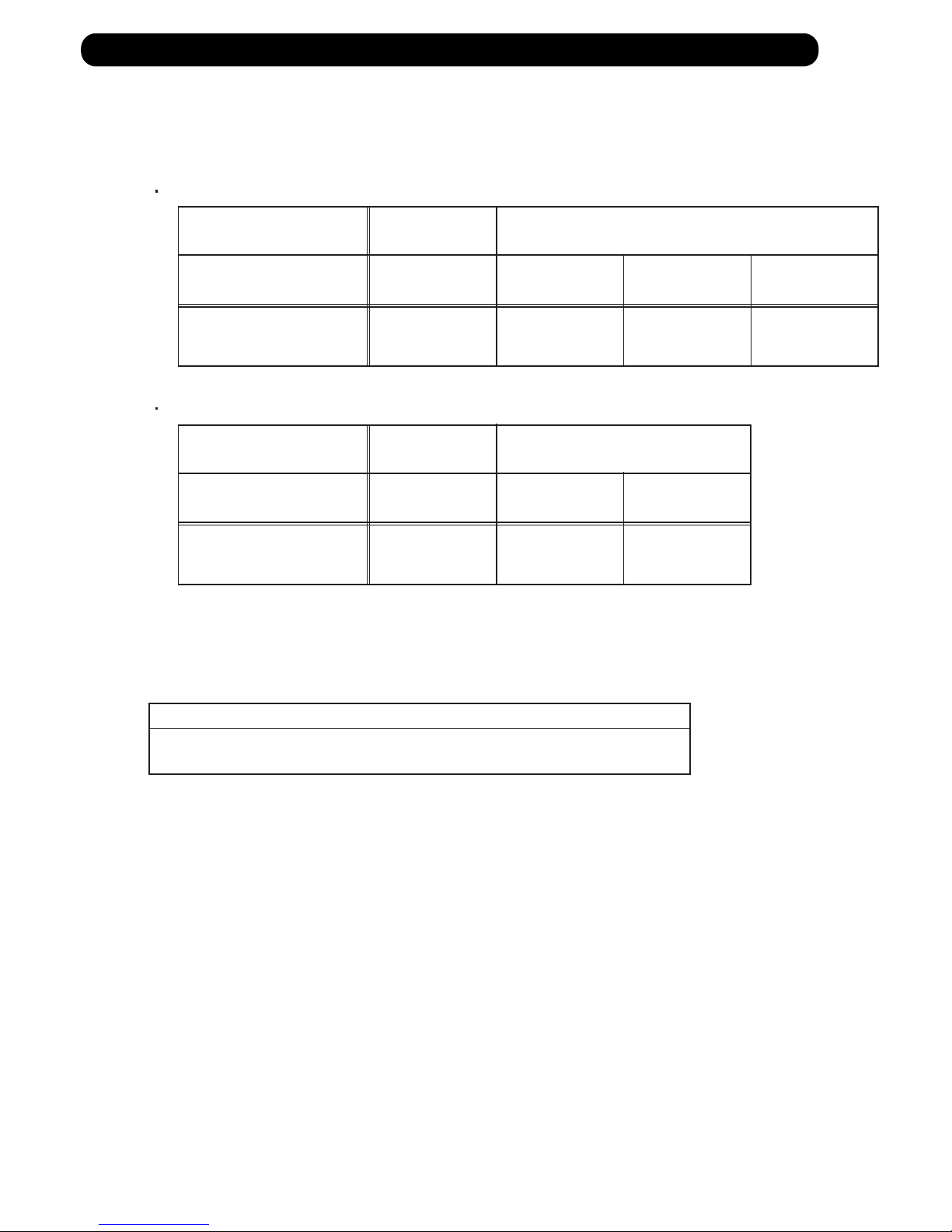
5. HIGH TEMPERATURE RELEASE CONTROL ( HEATING MODE )
On heating mode, the compressor frequency is controlled as following based on the
detection value of the indoor heat exchanger temperature sensor.
(Fig.14 : Heating Overload Protection Control)
05-22
53°C
- 20°C
50°C
67°C
62°C
59°C
Refer to below
Compressor Operation
Over than 18Hz Frequency down every 60 seconds
Less than 18Hz OFF
4. COOLING PRESSURE OVER RISE PROTECTION
On cooling mode, the compressor frequency is controlled as following based on the
detection value of the outdoor heat exchanger temperature sensor.
Outdoor heat exchange
temperature
(Fig.13 : Cooling Pressure Over Rise Protection Control)
Compressor is OFF
Hold
(AR*A12 - 24LATN)
The compressor frequency is
decreased 2Hz every 60seconds.
(AR*A36/ 45LATN)
The compressor frequency is
decreased 5Hz every 60seconds.
Release of protection
The forced cooling operation starts up when MANUAL / AUTO button is pressed more than 10 seconds.
During the forced cooling operation, it keeps operation regardless of detection value of room
temperature sensor.
Operation LED and Timer LED light up while the unit is on the forced cooling operation.
The forced cooling operation is released after 60 minutes from starting time.
Cooling
Heating
5-22. FORCED COOLING OPERATION
5-23. COMPRESSOR STOP CONTROL
When the detection value of outdoor temperature sensor is lower than temperature
in the table below, the compressor is stopped.
(Table 15 : Operation temperature of compressor stop control)
Operation
temperature
Temperature
Page 50

6 . REFRIGERANT CAUTION -R410A-
R410A
INVERTER
DUCT type
Page 51

6-1. R410A TOOLS
Gauge manifold . . . . . . . . . . . . . . . . . . . . . (Fig.4-1)
Since the normal pressure is high, the connection pipe size
is also different.
Charge hose . . . . . . . . . . . . . . . . . . . . . . . (Fig.4-2)
Refrigerant cylinder . . . . . . . . . . . . . . . . . (Fig.4-3)
Confirm the refrigerant type before charging. Always
charge liquid-phase refrigerant.
Electronic balance for refrigerant
charging . . . . . . . . . . . . . . . . . . . . . . . . . . . (Fig.4-4)
Electronic balance is recommended as in the case of
R410A.
Vacuum pump with adapter to prevent
reverse flow . . . . . . . . . . . . . . . . . . . . . . . .(Fig.4-5)
Conventional pump can be used.
Vacuum holder . . . . . . . . . . . . . . . . . . . . . (Fig.4-6)
Conventional pump can be used if adapter for preventing
vacuum pump oil from flowing back is used.
Gas leakage tester . . . . . . . . . . . . . . . . . . (Fig.4-7)
Exclusive for HFC
Refrigerant cleaner . . . . . . . . . . . . . . . . . . (Fig.4-8)
Brown paint as designated by the ARI, USA
Flare tool . . . . . . . . . . . . . . . . . . . . . . . . . . (Fig.4-9)
Torque wrench . . . . . . . . . . . . . . . . . . . . (Fig.4-10)
Refrigerant recovering
equipment (Collector) . . . . . . . . . . . . . . (Fig.4-11)
The type which can be used for any refrigerant is available
Nitrogen cylinder . . . . . . . . . . . . . . . . . . . (Fig.4-12)
This prevents an oxide film from forming in the pipe silveralloy brazing work by turning the air out of the pipe and
preventing the inside combustion.
Safety charger . . . . . . . . . . . . . . . . . . . . . (Fig.4-13)
It is always compulsory to change the liquid, because
R410A is a mixed refrigerant and there is some fear that a
mixing ratio changes. In order to avoid the refrigerant from
returning to the compressor in a liquid state, the refrigerant
can be charged instead of giving a load to the compressor
with a safety charger.
Control valve . . . . . . . . . . . . . . . . . . . . . . (Fig.4-14)
The control valve prevents the refrigerant from spouting
when it is removed, as the charging hose side and the service port side are possible to open and close at the same
time.
Thermistor vacuum gauge . . . . . . . . . . . (Fig.4-15)
To remove moisture from the refrigerating cycle completely, it is necessary to perform appropriate vacuum drying.
For that reason, vacuum conditions can be confirmed certainly.
Vacuum valve . . . . . . . . . . . . . . . . . . . . . (Fig.4-16)
This valve builts in a check valve, and it is easily possible
to vacuum a refrigerating cycle or check for degree of vacuum with it.
TOOLS AND EQUIPMENT (R410A)
Gauge Manifold
R410A
R22, R407C
High
pressure
gauge
Compond
gauge
Port size
-0.1 5.3
Mpa
-0.1 3.8
Mpa
1/2UNF
5/16"
-0.1 3.5
Mpa
-0.1 1.7
Mpa
7/16UNF
1/4"
*
1
Charge hose
R410A
R22, R407C
Normal
pressure
Port size
5.1 Mpa
27.4 Mpa
1/2UNF
3.4 Mpa
17.2 Mpa
7/16UNF
*
2
Breaking
pressure
This air conditioner used R410A.
For installation and servicing, it is necessary to prepare the
tools and machines that are different from the previous
refrigerant.
Mark shows the exclusive use for R410A.
The specification of the gauge is different due
to higher pressure.
The size of connection pipe is also different to
prevent mis-use.
The shape of flare is different for
high pressure condition.
06-01
Gas charging
Vacuuming
Piping work
Pressure control and
Circuit switching
Charge hose
Fig.4-2
Outdoor unit
Electronic charging
scale Fig.4-4
Vacuum pump Fig.4-5
Thermistor vacuum gauge Fig.4-15
Vacuum
Valve Fig.4-16
Safety charger Fig.4-13
Control Valve
Fig.4-14
Vacuum holder Fig.4-6
Leakage tester Fig.4-7
Cleaner Fig.4-8
Collector Fig.4-11
Nitrogen Cylinder
Fig.4-12
Torque wrench
Fig.4-10
Flare tool
Fig.4-9
Gauge manifold
Fig.4-1
Fig.4-3
Refrigerant cylinder
Vacuum control
Low pressure
High pressure
side
side
6. REFRIGERANT CAUTION -R410A-
Page 52

6-2. PRECAUTION FOR INSTALLATION
06-02
Precaution for installation
The pipe must be properly pressure rated for R410A
The pipe must be an air-conditioning refrigerant pipe.
Flare and flare nuts
Diameter 1/4 ” (6.35mm) 3/8” (9.52mm) 1/2 ”(12.7mm)
Refrigerant
R410A
R22
/R407C
R410A R410A
A 9.1 9.0 13.2 13.0 16.6
16.2
B 13 12 20 15 13 20
C 12 11 16 12.5 19 16
Nut width 17 22 26 24
Always use the flare nut that is packed
with the product.
Do not use existing (for R22) pipes
•
Be sure to use new pipes when replacing
conventional (R22) model with HFC
(R407C, R410A) model.
•
If you use existing pipes, it may cause
resolution of compressor oil by remaining
mineral oil.
3/8” (15.88mm)
R410A
22
29
19.7
25
R22
/R407C
R22
/R407C
R22
/R407C
19.4
23
20
27
3/4” (19.05mm)
R410A
24
36
24
29
R22
/R407C
23.7
29
24
Material
Nominal diameter
(in)
1/4" 3/8" 1/2" 5/8" 3/4" 7/8" 1 1/8" 1 1/4" 1 1/2"1 3/8"1"
6.35 9.52 12.70 15.88 19.05 22.22 28.58 31.75 38.1034.9225.40
Outside diameter
(mm)
Wall thickness
(mm)
0.8 0.8 0.8 1.0 1.2 1.0 1.0 1.1 1.31.21.0
1) Allowable tensile stress 33 (N/mm );
>
=
2
2) Allowable tensile stress 61 (N/mm ); 3) Design pressure 4.2MPa.
>
=
2
JIS H3300-C1220T-H or equivalent
2)
COPPER
JIS H3300-C1220T-O or equivalent
1)
COPPER
3)
Pipe diameter, recommended material and wall thickness
A
C
B
Page 53

Be careful not to mix moisture and
contamination into the pipe
Moisture and contamination
in the pipe is a cause of
trouble.
Air purge
Always use a
vacuum pump
to purge air.
Refrigerant charge
Do it always from the liquid phase
side.
Don't charge from the gas phase side.
Compressor oil is changed
Be careful to handle synthetic oil, since it
resolves easily by moisture and
contamination.
Don't mix new synthetic oil and mineral oil.
It may cause trouble.
We developed new synthetic oil, since HFC
refrigerant doesn't dissolve in mineral (for R22)oil.
06-03
Page 54

6-3. PRECAUTION FOR SERVICING
Feature 1 Refrigerant oil is different from before.
Refrigerant oil for
New Refrigerant
Synthetic oil
Ether
Esther
Different point from
previous one
Previously it was
mineral oil.
Absorbent character
is high.
Contamination occurs
when mixed withe other
kind of oil.
Use the gauge manifold and charge hose
for New Refrigerant(HFC), which shall
be segregated from those of R22.
Attach the stop valve on the vacuum pump
and avoid the oil from reverse frow.
It is necessary to use the vacuum pump
which can obtain the high vacuum condition.
Precaution on Tools
Feature 2 New Refrigerant has Approx 1.6 times higher pressure than previous refrigerant.
R410A
High Pressure
Different point from
previous one
Diameter of Service port
has been changed from
1/4 Flare to 5/16 Flare.
It requires the gauge manifold and charge
hose exclusively for R410A.
It requires the flare tool and torque wrench
that satisfies New JIS standard.
Precaution on Tools
R410A R22
1.6 times of R22.
JIS standard of flare
process It became lager
To keep thethickness of
copper tube.
(1/4,3/3=more than 0.8mm)
Previous flare tool + flare adapter can be used as well.
06-04
Page 55
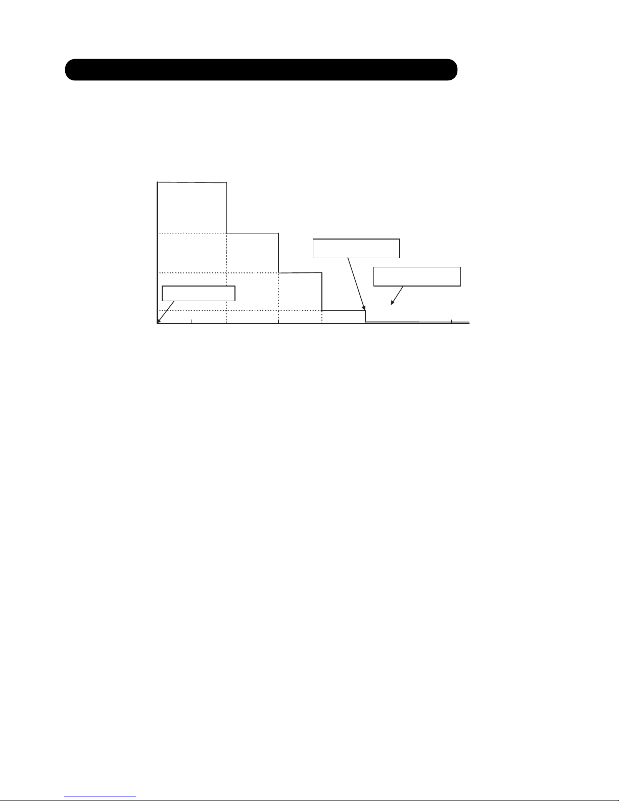
6-4. NEW REFRIGERANT R410A
What is HFC ?
Phase-out schedule of HCFC
according to Montreal protocol
1996 20102000 2004 2015 2020 2030
60
40
20
100
(Year)
(%)
80
(HCFC consumption of 1989) +
(CFC consumption of 1989) x 2.8%
65%
35%
10%
0.5%
started control
only service use
total abolition
100% =
0
*
06-05
Page 56
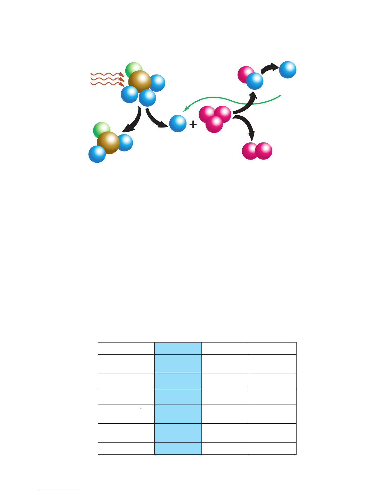
Ozone Layer depleting mechanism
CFC
CFCl
2
Cl Ozone
(O3)
O
2
ClO
Cl
sunbeam
What is CFC and HCFC?
CFC : Chloro-Fluoro-Carbon
High ODP( ozone depletion potential ) chemical compound, including chlorine. (ODP:0.6-1.0)
For example : R12 (for refrigerator and car air-conditioner)
Low ODP chemical compound, including chlorine and hydrogen. (ODP:0.02-01)
HCFC : Hydro-Chloro-Fluoro-Carbon
For example : R22 (for air-conditioner)
R134a (for Car air conditioner)
HFC3 : Hydro-Fluoro-Carbon
R407C (for air conditioner)
Refrigerant characteristics
R22
Composition
(wt%)
R22
(100)
Boiling Point
- 40.8
Behavior ---
Pressure at 54.5
C
(kPa)
2,151
Temperature Glide
(deg)
0
ODP 0.055
R407C
R32/R125/R134a
(23/25/52)
- 43.6
zeotrope
2,262
5.4
0
R410A
R32/R125
(50/50)
- 51.4
near azeotrope
3,406
0.11
0
06-06
Page 57
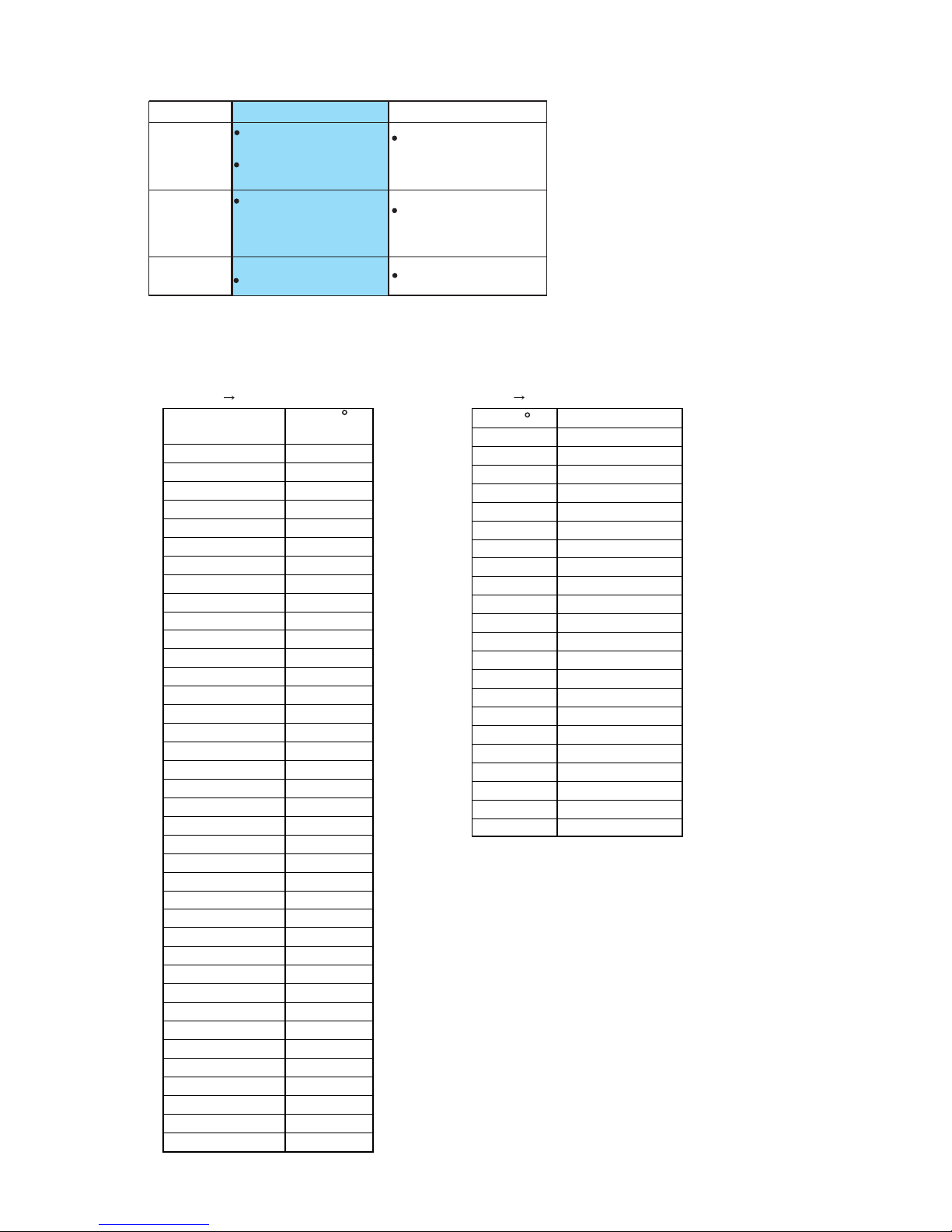
Summary of R407C and R410A characteristics
Pressure (Mpa) Temp ( C)
2.20 37.9
2.25 38.7
2.30 39.6
2.35 40.5
2.40 41.3
2.45 42.1
2.55 43.8
2.60 44.6
2.65 45.3
2.70 46.1
2.75 46.8
2.80 47.6
2.85 48.3
2.90 49.0
2.95 49.8
3.00 50.5
3.05 51.2
3.10 51.9
3.15 52.6
3.20 53.2
3.25 53.9
3.30 54.6
3.35 55.3
3.40 55.9
3.45 56.5
3.50 57.1
2.55 57.8
3.60 58.4
3.65 59.0
3.70 59.6
3.75 60.2
3.80 60.8
3.85 61.4
3.90 52.0
3.95 62.5
4.00 63.1
4.05 63.6
4.10 64.2
4.15 64.8
Temp ( C) Pressure (Mpa)
39 2.27
40 2.32
41 2.38
42 2.44
44 2.57
45 2.63
46 2.69
47 2.76
48 2.83
49 2.90
51 3.04
52 3.11
53 3.18
54 3.26
56 3.41
57 3.49
58 3.57
59 3.65
61 3.82
62 3.90
63 3.99
64 4.08
Desighed pressure of R410A refrigerant
< Pressure Temp >
Relation between R410A condensing temperature and saturated pressure.
< Temp Pressure >
Advantage
Disadvantage
Suitable for
R410A
higher system
performance
Near-Azeotropic
refrigerant
1.6 times higher
(difficult to design against
pressure resistance)
Small Air-Conditioners
pressure than R22
R407C
similar pressure as R22
(possible to design
large equipment)
Zeotropic refrigerant
(handle with care)
Large Air-Conditioners
*
05-07
Page 58

OIL
• Use new synthetic oils such as ester because HFC series refrigerant has less solubility with mineral oils
conventionally used for R22.
• As these new synthetic oils are easily influenced by moisture and dusts, they must be treated more care-
fully than the conventional lubricating oils.
CAUTION
For installation/servicing, take more precautions than the case of conventional refrigerants to avoid moisture
and dusts entering the refrigerant circuit. Also, for storing parts, more precautions must be taken.
2, 3-WAY VALVE
• Review material O-ring, valve core seal for securing suitability with oil.
CAUTION
Check if the valve is suitable for the refrigerant (model) when replacing.
CAUTION
Check if the compressor is suitable for the refrigerant (model) when replacing. Complete welding within 15minutes
after opening the cap when replacing.
COMPRESSOR
• Use better grade of material for sliding parts for securing good lubrication of sliding part as HFC
refrigerant does not contain chloride.
• Review insulating materials
• Increase pressure resistance strength
CAUTION
During storage, due care must be taken so that foreign matters such as dust and water do not enter.
HEAT EXCHANGER
• Review the water,contaminants controlling level
• Use thinner tube to increase pressure Increase capacity for resistance strength (only outdoor unit)
improving performance
CAUTION
Check if the valve is suitable for the refrigerant (model) when replacing.
4-WAY VALVE
• Review materials
6-5. DEFFERENCE FROM CONVENTIONAL MODEL (R22) AND PRECAUTIONS
06-08
Check Valve
Other Piping
CAUTION
Check if the valve is suitable for the refrigerant (model) when replacing.
• Review materials
Change shape of pipe ends to increase pressure resistance strength.
•
•
Review the water, contaminants controlling level.
Review thickness of pipes.
•
CAUTION
During storage, due care must be taken so that foreign matters such as dust and water do not enter.
Page 59

7 . TROUBLE SHOOTING
R410A
DUCT type
INVERTER
Page 60
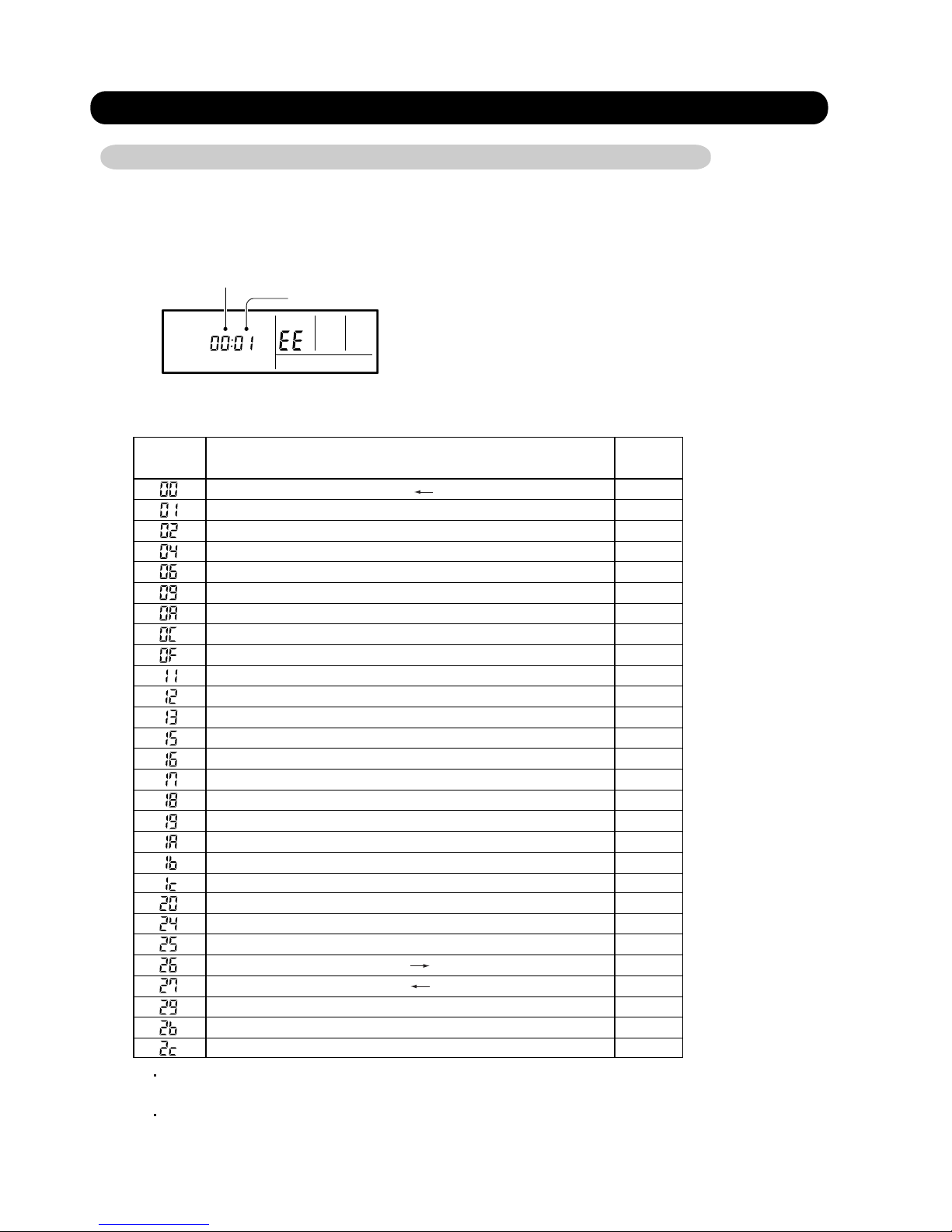
7. TROUBLESHOOTING
07-01
7-1 ERROR DISPLAY
When "EE" in Temperature Display is displayed, inspection of the air conditioning system is necessary.
Please consult authoilzed servise personnel.
Error code
Error contents
Trouble
shooting
Communication error (Serial reverse transfer error)
Room temperature sensor error
Indoor heat exchanger temperature sensor error
Outdoor heat exchanger temperature sensor(outlet) error
Outdoor heat exchanger temperature sensor(middle) error
Water drain abnormal
Outdoor temperature sensor error
Outdoor discharge pipe temperature sensor error
Discharge temperature error
Indoor fan motor abnormal
Outdoor unit fan motor error
Outdoor communication signal error (Forward transfer signal error)
7-1-1 WIRED REMOTE CONTROLLER DISPLAY
Pressure switch error
Active filter module (AFM) error
CT error
Communication error (indoor unit remote control)
Communication error (Main PCB Display PCB)
Communication error (Main PCB Display PCB)
IPM error
Compressor rotor location cannot detect (permanent stop)
Compressor temperature sensor error
Compressor temperature error
4-way valve error
1. SELF - DIAGNOSIS
1
2
5
*(6)
7
8
10
11
12
13
14
15
16
17
18
19
20
21
22
23
*(24)
*(25)
26
27
28
Outdoor unit computer communication error
Indoor manual auto switch error
Exessive high pressure protection on cooling
PFC circuit error
3
4
SUMOTUWETH FR
SA
Unit number (usually 0)
Error code
ex. Self-diagnosis check
Indoor EEPROM abnormal (Model No.)
9
If “CO” appears in the unit number display, there is a remote controller error.
Refer to the installation instruction sheet included with the remote controller.
Trouble shooting No.6,24,and 25 have no application in this models.
Page 61
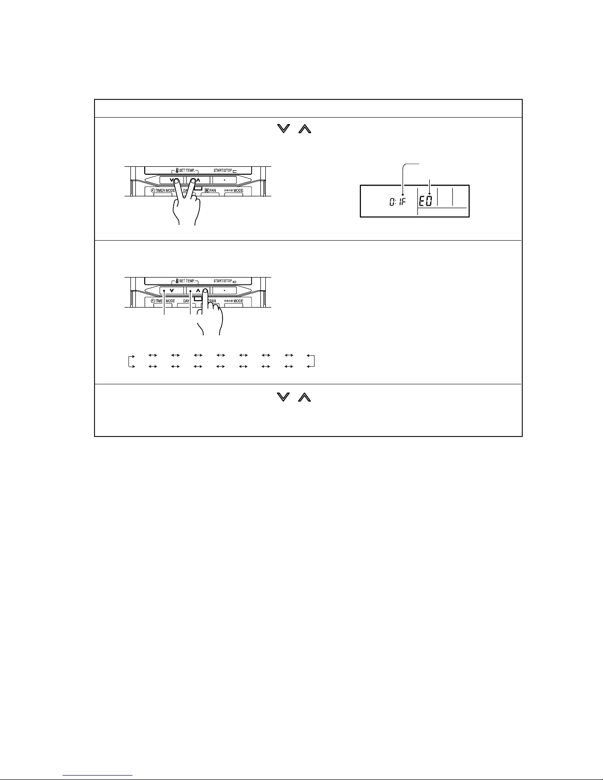
07-02
1. Stop the air conditioner operation.
2. Press the SET TEMPERATURE buttons , simultaneously for 3 seconds
or more to start the self-diagnosis.
4. Press the SET TEMPERATURE buttons , simultaneously for 3 seconds or more
or there is no key input for 60 seconds to stop the display.
2. ERROR CODE HISTORY DISPLAY
Up to 16 memorized error codes may be displayed for the indoor unit connected to the remote controller.
3. Press the SET TEMPERATURE button to select the error history number.
SUMOTUWETH FR
SA
Error code
Error history number
0 1 2 3 4 5 6 7
F E d c b A 9 8
Lower
Raise
Page 62
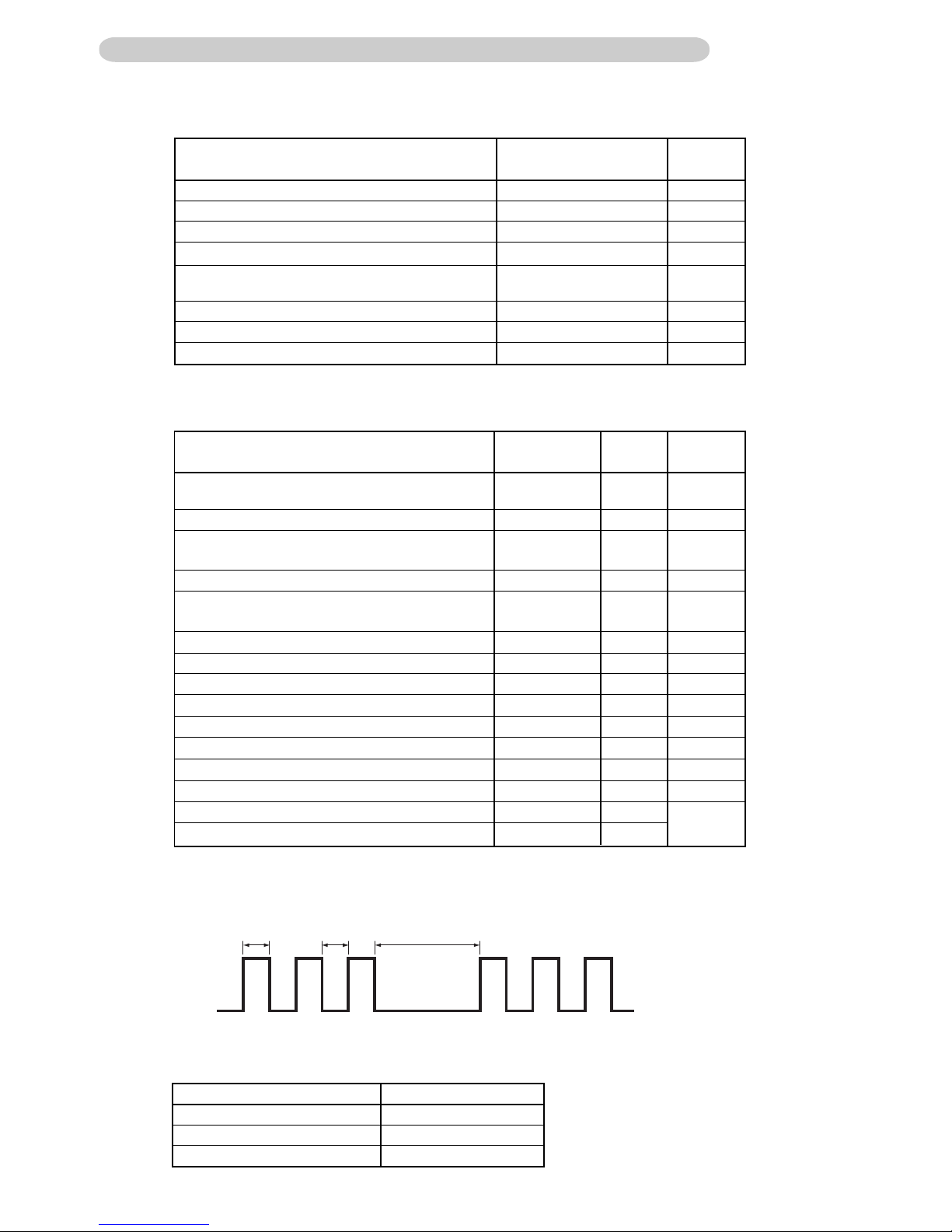
07-03
Error contents
LED Flashing
Pattern
Display
priority
Trouble
shooting
Outdoor communication signal error
(Forward transfer signal error)
1 time flash
2 times blink
3 times blink
4 times blink
7 times blink
8 times blink
9 times blink
12 times blink
13 times blink
14 times blink
15 times blink
16 times blink
1
2
3
4
7
8
9
11
12
13
14
15
Outdoor heat exchanger
temperature(outlet) sensor error
Outdoor temperature sensor error
Outdoor discharge pipe temperature sensor error
Outdoor unit fan motor error (upper fan)
Outdoor unit fan motor error (lower fan)
Pressure switch abnormal
IPM error
Compressor rotor location cannot detect
Compressor Start-up error
Compressor temperature sensor error
10 times blink
10
Compressor temperature error
Compressor temperature error
Heat sink temperature sensor error
Operation LED Blinking Pattern
Normal operation OFF
5sec ON / 1sec OFF
0.5sec ON / 0.5sec OFF
2sec ON / 2sec OFF
0.1sec ON / 2sec OFF
0.1sec ON / 0.1sec OFF
5sec ON / 5sec OFF
2sec ON / 5sec OFF
5sec ON / 2sec OFF
Continuously lighting
Protected operation
1sec ON / 1sec OFF
Pump down operation
0.5sec 0.5sec 2sec
ON
OFF
1. ERROR DISPLAY
Outdoor LED Blink (1 to 16 times) 0.5sec ON / 0.5sec OFF blinking
7-1-2 OUTDOOR UNIT DISPLAY
12
8
5
5 times blink
5
Outdoor heat exchanger
temperature(middle) sensor error
7
13
26
9
6 times blink
6
Discharge temperature error
Discharge temperature error
29
14
27
15
18
30
19
Outdoor unit fan motor error
19
Error contents
LED Flashing Pattern
Trouble
shooting
Outdoor unit sensor error
(Discharge or Outdoor or Heat EX(In)(Out))
IPM error
Compressor rotor location cannot detect
15
9
5,7,8,26
27
23
CT error
16
18,30
1-1. For AR*A12L/ 14L/ 18L/ 24L (AO*A12L/ 14L/ 18L/ 24L)
1-2. For AR*A36L/ 45L (AO*A36L/ 45L)
1-2-1. ERROR DISPLAY METHOD
1-2-2. NORMAL OPERATION DISPLAY
PFC circuit error
Page 63
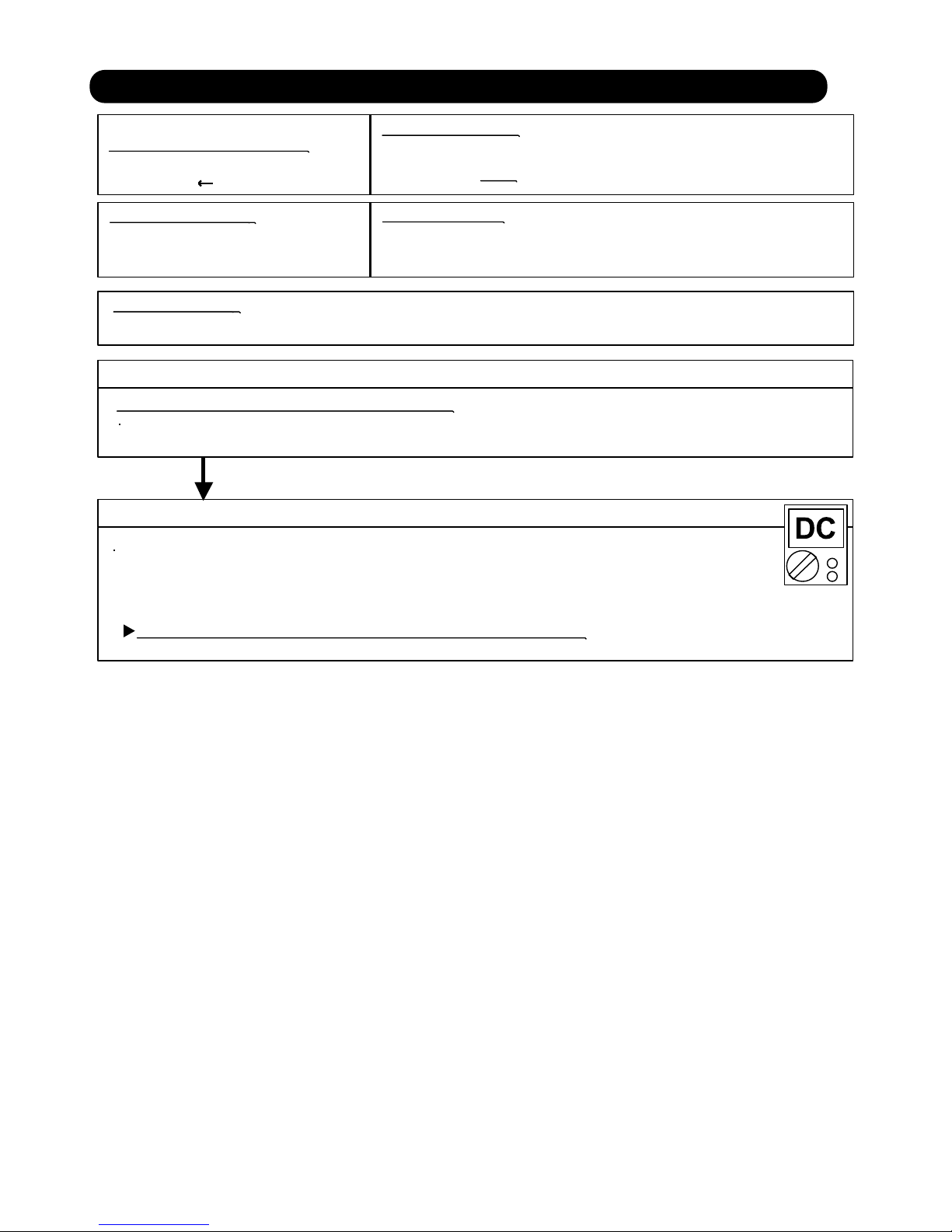
Trouble shooting 1
INDOOR UNIT Error Method:
Detective Actuators:
Detective details:
Forecast of Cause:
Check Point 2 : Check Remote Control and Controller PCB
Check Point 1 : Check the connection of terminal
OKOK
Indicate or Display:
ERROR CODE : E : 00
Outdoor Unit : No indication
Communication Error
(Indoor unit Remote control)
Indoor unit controller PCB circuit
Wired Remote Control
1. Terminal connection abnormal 2. Wired Remote Control failure 3. Controller PCB failure
After turning off the power, check & correct the followings.
Check the connection of terminal between remote control and Indoor unit,
and check if there is a disconnection of the cable.
Upon correcting the removed connector or mis-wiring, reset the power.
Check Voltage at CN14 (terminal 1-3) of Controller PCB.
(Power supply to Remote Control)
>> If it is DC12V, Remote Control is failure. (Controller PCB is normal) >> Replace Remote Control
>> If it is DC 0V, Controller PCB is failure. (Check Remote Control once again) >> Replace Controller PCB
When the indoor unit cannot receive the signal from Wired Remote
more than 10seconds after power ON, or the indoor unit cannot receive
the signal more than 1minute during normal operation.
07-04
7-2 TROUBLE SHOOTING WITH ERROR CODE
Page 64

Trouble shooting 2
OUTDOOR UNIT Error Method:
Detective Actuators:
Detective details:
Forecast of Cause:
OK
Indicate or Display:Indicate or Display:
Outdoor Unit : No indication
ERROR CODE : E : 01
YESYES
NO
N
L
3
2
1
WHITE
BLACK
RED
WHITE
BLACK
+
-
OK
Communication Error
(Serial Reverse Transfer Error)
Outdoor Unit Main PCB Circuit
Active Filter Module
1. Connection failure 2. External cause 3. Main PCB failure 4. Active Filter Module failure
Check Point 1-1 : Reset the power and operate
Does Error indication show again?
Check Point 1-2:
Check external cause such as noise
Check the complete insulation of the grounding.
Check if there is any equipment that causes harmonic wave
near the power cable (Neon light bulb or any electronic
equipment which causes harmonic wave).
Check Point 2 : Check Connection
Check any loose or removed connection line of
Indoor unit and Outdoor unit.
>> If there is an abnormal condition, correct it by
referring to Installation Manual or Data &
Technical Manual.
Check connection between Outdoor Unit Main PCB
and Filter PCB.
(If there is loose connector or open cable)
Check Point 3 : Check the voltage of power supply
Check the voltage of power supply
>> Check if AC198 - 264V appears at Outdoor Unit Terminal L - N.
Check Point 4 : Check Serial Signal (Reverse Transfer Signal)
Check Serial Signal (Reverse Transfer Signal)
>> Check if Indicated value swings between AC70V and AC130V at Outdoor Unit Terminal 1 - 3.
>> If it is abnormal, Check Active Filter Module. (PARTS INFORMATION 3)
When the indoor unit cannot receive the serial signal from Outdoor unit
more than 10seconds,
then permanent stop after 20seconds.
>>If Active Filter Module is abnormal, replace it.
>>If Active Filter Module is normal, replace Main PCB.
07-05
Page 65
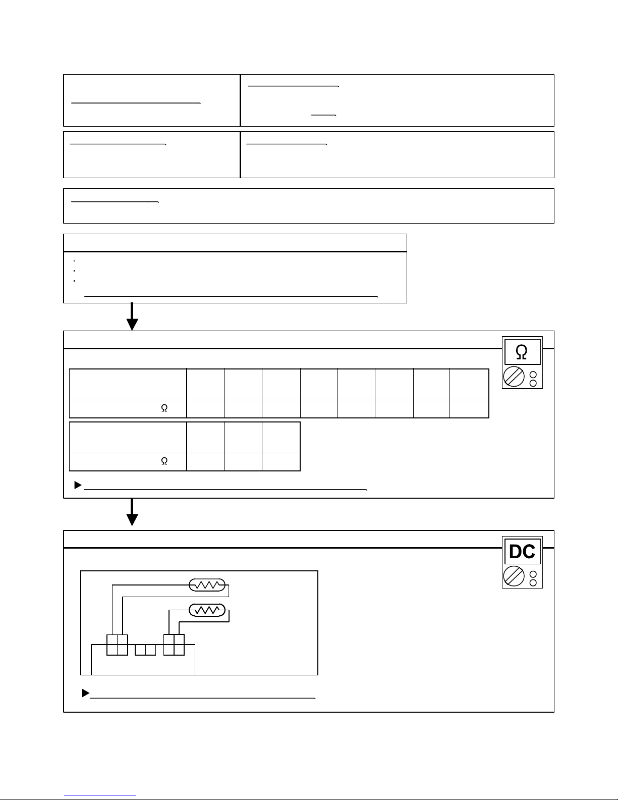
Trouble shooting 3
INDOOR UNIT
INDOOR UNIT Error Method:
Indicate or Display:
Outdoor Unit : No indication
ERROR CODE : E : 02
Detective Actuators:
Detective details:
Forecast of Cause :
Check Point 2 : Check Point 2 : Remove connector and check Thermistor resistance value
Check Point 1 : Check connection of Connector
Check Point 3 : Check Point 3 : Check voltage of Controller PCB (DC5.0V)
6.51
35°C
8.04
30°C
10.012.515.820.225.933.6Resistance Value (k )
25°C20°C15°C10°C5°C0°C
Temperature
OK
OK
3.594.355.30Resistance Value (k )
50°C45°C40°C
Temperature
THERMISTOR
(PIPE TEMP.)
THERMISTOR
(ROOM TEMP.)
GRAY
GRAY
BLACK
BLACK
CN5 CN7 CN8
1 2 1 2
1 2 1 2
Room Temperature Sensor Error
Indoor Unit Controller PCB Circuit
Room Temperature Thermistor
When Room Temperature Thermistor open or short-circuit is
detected at power ON.
1. Connector connection failure 2.Thermistor failure 3. Controller PCB failure
Check if connector is removed.
Check erroneous connection.
Check if thermistor cable is open.
>>Upon correcting the removed connector or mis-wiring, reset the power.
Thermistor Characteristics (Approx. value)
If Thermistor is either open or shorted, replace it and reset the power.
Make sure circuit diagram of indoor unit and check terminal voltage at Thermistor (DC5.0V)
If the voltage does not appear, replace Controller PCB.
07-06
1 2
Page 66

Trouble shooting 4
INDOOR UNIT
INDOOR UNIT Error Method:
Indicate or Display:
Outdoor Unit : No indication
ERROR CODE : E : 04
Detective Actuators:
Detective details:
Forecast of Cause :
Check Point 2 :
31.7
35°C
39.6
30°C
49.762.980.3103134176Resistance Value (k )
25°C20°C15°C10°C5°C0°C
Temperature
OKOK
OK
17.120.825.6Resistance Value (k )
50°C45°C40°C
Temperature
Indoor Heat Exchanger Temperature
Sensor Error
Indoor Unit Controller PCB Circuit
Heat Exchanger Temperature Thermistor
When Heat Exchanger Temperature Thermistor open or short-circuit is
detected at power ON.
1. Connector connection failure 2.Thermistor failure 3. Controller PCB failure
Check Point 1 : Check connection of Connector
Check if connector is removed.
Check erroneous connection.
Check if thermistor cable is open.
>>Upon correcting the removed connector or mis-wiring, reset the power.
Check Point 2 : Remove connector and check Thermistor resistance value
Thermistor Characteristics (Approx. value)
If Thermistor is either open or shorted, replace it and reset the power.
Check Point 3 : Check voltage of Controller PCB (DC5.0V)
Make sure circuit diagram of indoor unit and check terminal voltage at Thermistor (DC5.0V)
If the voltage does not appear, replace Controller PCB.
07-07
THERMISTOR
(PIPE TEMP.)
THERMISTOR
(ROOM TEMP.)
GRAY
GRAY
BLACK
BLACK
CN5 CN7 CN8
1 2 1 2
1 2 1 21 2
Page 67

Trouble shooting 5
OUTDOOR UNIT Error Method:
Indicate or Display:
Outdoor Unit (AR*A12L- 24L) : LED 0.1sec ON/ 0.1sec OFF
(AR*A36L/ 45L) : LED 3 times blink
For AR*A12L- 24L For AR*A36L/ 45L
ERROR CODE : E : 06
Detective Actuators:
Detective details:
Forecast of Cause :
Check Point 2 :
Check Point 3 :
4.77
25°C
5.98
20°C
7.569.6312.416.121.027.8Resistance Value (k )
15°C10°C5°C0°C-5°C-10°C
Temperature
OKOK
OKOK
DC
3.84
30°C
0.446
90°C
0.606
80°C
0.8401.191.712.082.533.11Resistance Value (k )
70°C60°C50°C45°C40°C35°C
Temperature
0.333
100°C
THERMISTOR
(PIPE OUT)
THERMISTOR
(DISCHARGE)
THERMISTOR
(COMPRESSOR)
THERMISTOR
(PIPE MID)
THERMISTOR
(OUTDOOR)
BLACK
CN70 CN72 CN73 CN71
CN24 CN21 CN22 CN23 CN26 CN25
2 13 2 1 4 3 2 12 1
BROWN
BROWN
BLACK
THERMISTOR
(PIPE MID)
THERMISTOR
(DISCHARGE)
THERMISTOR
(PIPE OUT)
THERMISTOR
(OUTDOOR)
THERMISTOR
(COMPRESSOR)
THERMISTOR
(HEAT SINK)
BLACK
BBROWN
BLACK
BLUE
BROWN
BLACK
BLACK
Outdoor Heat Exchanger Temperature
Sensor (Outlet) Error
Outdoor Unit Main PCB Circuit
Heat Exchanger Temperature
Thermistor (Outlet)
When Heat Exchanger Temperature Thermistor (Outlet) open or
short-circuit is detected at power ON or while running the compressor.
1. Connector connection failure 2.Thermistor failure 3. Main PCB failure
Check Point 1 : Check connection of Connector
Check if connector is removed.
Check erroneous connection.
Check if thermistor cable is open.
>>Upon correcting the removed connector or mis-wiring, reset the power.
Check Point 2 : Remove connector and check Thermistor resistance value
Thermistor Characteristics (Approx. value)
If Thermistor is either open or shorted, replace it and reset the power.
Check Point 3 : Check voltage of Main PCB (DC5.0V)
Make sure circuit diagram of outdoor unit and check terminal voltage at Thermistor (DC5.0V)
If the voltage does not appear, replace Main PCB.
07-08
2 13 2 1 4 3 2 12 1
1 2
1 2
1 2
1 2
1 2
1 2
1 2
1 2
1 2
1 2
1 2
1 2
Page 68
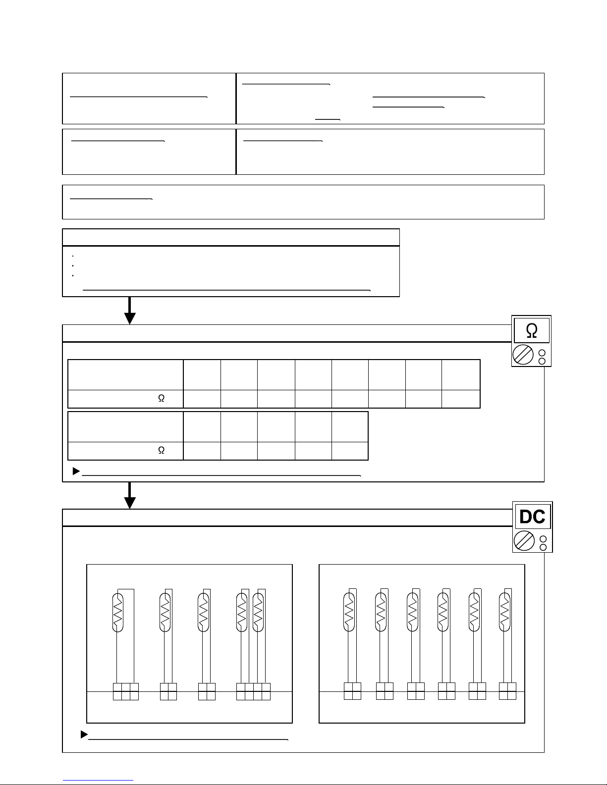
Trouble shooting 7
INDOOR UNIT
OUTDOOR UNIT Error Method:
Indicate or Display:
ERROR CODE : E : 0A
Detective Actuators:
Detective details:
Forecast of Cause :
Check Point 2 :
Check Point 3 :
OKOK
OKOK
30°C
12.620.726.935.246.662.3115Resistance Value (k )
20°C
16.1
15°C10°C5°C0°C-20°C -10°C -5°C
Temperature
3.45 2.36 1.65Resistance Value (k )
50°C 60°C 70°C
5.187.97
40°C
Temperature
Outdoor Temperature Sensor Error
Outdoor Unit Main PCB Circuit
Outdoor Temperature Thermistor
When Outdoor Temperature Thermistor open or short-circuit is
detected at power ON or while running the compressor.
1. Connector connection failure 2.Thermistor failure 3. Main PCB failure
Check Point 1 : Check connection of Connector
Check if connector is removed.
Check erroneous connection.
Check if thermistor cable is open.
>>Upon correcting the removed connector or mis-wiring, reset the power.
Check Point 2 : Remove connector and check Thermistor resistance value
Thermistor Characteristics (Approx. value)
If Thermistor is either open or shorted, replace it and reset the power.
Check Point 3 : Check voltage of Main PCB (DC5.0V)
Make sure circuit diagram of outdoor unit and check terminal voltage at Thermistor (DC5.0V)
If the voltage does not appear, replace Main PCB.
07-09
Outdoor Unit (AR*A12L- 24L) : LED 0.1sec ON/ 0.1sec OFF
(AR*A36L/ 45L) : LED 4 times blink
For AR*A12L- 24L For AR*A36L/ 45L
THERMISTOR
(PIPE OUT)
THERMISTOR
(DISCHARGE)
THERMISTOR
(COMPRESSOR)
THERMISTOR
(PIPE MID)
THERMISTOR
(OUTDOOR)
BLACK
CN70 CN72 CN73 CN71
CN24 CN21 CN22 CN23 CN26 CN25
2 13 2 1 4 3 2 12 1
BROWN
BROWN
BLACK
THERMISTOR
(PIPE MID)
THERMISTOR
(DISCHARGE)
THERMISTOR
(PIPE OUT)
THERMISTOR
(OUTDOOR)
THERMISTOR
(COMPRESSOR)
THERMISTOR
(HEAT SINK)
BLACK
BBROWN
BLACK
BLUE
BROWN
BLACK
BLACK
2 13 2 1 4 3 2 12 1
1 2
1 2
1 2
1 2
1 2
1 2
1 2
1 2
1 2
1 2
1 2
1 2
Page 69

Trouble shooting 8
INDOOR UNIT
OUTDOOR UNIT Error Method:
Indicate or Display:
ERROR CODE : E : 0C
Detective Actuators:
Detective details:
Forecast of Cause :
Check Point 2 :
Check Point 3 :
17.826.3
20°C
40.062.679.1101130169Resistance Value (k )
15°C10°C5°C0°C
Temperature
OKOK
OKOK
12.3
30°C
50°C40°C
60°C
1.222.003.434.606.278.70Resistance Value (k )
140°C120°C100°C
90°C80°C70°C
Temperature
Outdoor Discharge Pipe Temperature
Sensor Error
Outdoor Unit Main PCB Circuit
Discharge Pipe Temperature Thermistor
When Discharge Pipe Temperature Thermistor open or short-circuit
is detected at power ON or while running the compressor.
1. Connector connection failure 2.Thermistor failure 3. Main PCB failure
Check Point 1 : Check connection of Connector
Check if connector is removed.
Check erroneous connection.
Check if thermistor cable is open.
>>Upon correcting the removed connector or mis-wiring, reset the power.
Check Point 2 : Remove connector and check Thermistor resistance value
Thermistor Characteristics (Approx. value)
If Thermistor is either open or shorted, replace it and reset the power.
Check Point 3 : Check voltage of Main PCB (DC5.0V)
Make sure circuit diagram of outdoor unit and check terminal voltage at Thermistor (DC5.0V)
If the voltage does not appear, replace Main PCB.
07-10
Outdoor Unit (AR*A12L- 24L) : LED 0.1sec ON/ 0.1sec OFF
(AR*A36L/ 45L) : LED 2 times blink
For AR*A12L- 24L For AR*A36L/ 45L
THERMISTOR
(PIPE OUT)
THERMISTOR
(DISCHARGE)
THERMISTOR
(COMPRESSOR)
THERMISTOR
(PIPE MID)
THERMISTOR
(OUTDOOR)
BLACK
CN70 CN72 CN73 CN71
CN24 CN21 CN22 CN23 CN26 CN25
2 13 2 1 4 3 2 12 1
BROWN
BROWN
BLACK
THERMISTOR
(PIPE MID)
THERMISTOR
(DISCHARGE)
THERMISTOR
(PIPE OUT)
THERMISTOR
(OUTDOOR)
THERMISTOR
(COMPRESSOR)
THERMISTOR
(HEAT SINK)
BLACK
BBROWN
BLACK
BLUE
BROWN
BLACK
BLACK
2 13 2 1 4 3 2 12 1
1 2
1 2
1 2
1 2
1 2
1 2
1 2
1 2
1 2
1 2
1 2
1 2
Page 70
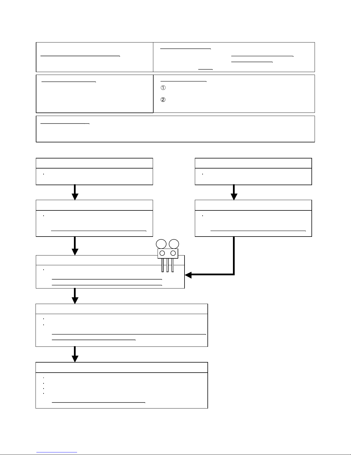
Trouble shooting 9
INDOOR UNIT
OUTDOOR UNIT Error Method:
Indicate or Display:
ERROR CODE : E : 0F
Detective Actuators:
Detective details:
Forecast of Cause :
Discharge temperature error
Outdoor Unit Main PCB Circuit
Discharge Pipe Temperature Thermistor
07-11
Outdoor Unit (AR*A12L- 24L) : LED continuously lighting
(AR*A36L/ 45L) : LED 6 times blink
When the discharge temperature becomes higher than 110°C
( AR*A36L and 45L is 115°C ), the compressor stops.
After the compressor restarts, if the same operation is repeated,
the compressor stops permanently.
Check Point 1 : Check if Gas Valve is open
If it is not open, open it and check the operation.
Check Point 3 : Check if gas leak or less gas
Measure Gas pressure, if there is a leak, correct it.
>>If recharging refrigerant, make sure to perform
vacuuming and recharge the specified amount.
Check Point 5 : Check Outdoor FAN, Heat Exchanger
Is there anything obstructing the air distribution circuit?
Is there any clogging of Outdoor Heat Exchanger?
Is the Fan rotating? (Check by hand and if it is locked, replace the motor)
Check Outdoor Fan Motor.
>>If the Fan Motor is defective, replace it.
Check Point 4 : Check Discharge Thermistor
Isn’t it fallen off the holder?
Is there a cable pinched?
>> Check characteristics of thermistor (Refer to Trouble shooting 8),
If defective, replace the thermistor
Check Point 2 : Check EEV and Strainer
Are EEV and Strainer open?
(Refer to PARTS INFORMATION 4)
>>If EEV or Strainer is defective, replace it.
OK OK
OK
OK
OK
OK
MPa MPa
1. Valve is close 2. EEV failure 3. Gas Leak, less 4. Discharge Thermistor failure
5. Outdoor Fan Operation failure 6. Outdoor Heat Exchanger clogged
< Cooling mode >
< Heating mode >
Check Point 1 : Check if LIquid Valve is open
If it is not open, open it and check the operation.
Check Point 2 : Check EEV and Strainer
Are EEV and Strainer open?
(Refer to PARTS INFORMATION 4)
>>If EEV or Strainer is defective, replace it.
Page 71
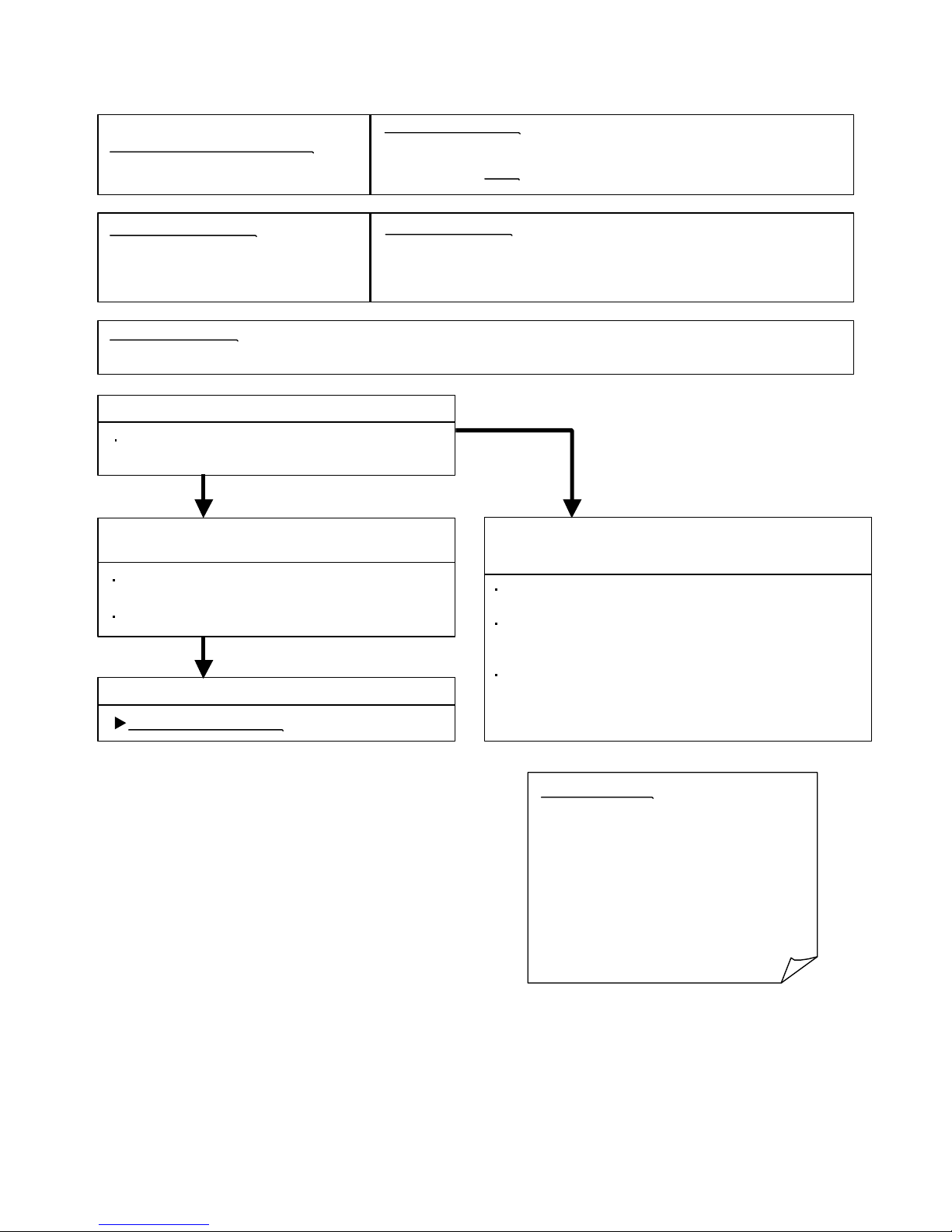
Detective Actuators:
Detective details:
Forecast of Cause:
Check Point 3 : Replace Controller PCB
Check Point 2 :
Check Indoor Unit electric components
YESYES
NO
Trouble shooting 10
INDOOR UNIT Error Method:
Indicate or Display:
Indicate or Display:
Outdoor Unit : No indication
ERROR CODE : E : 11
Indoor EEPROM abnormal
(Model No.)
Indoor Unit Controller PCB circuit
1. External cause 2. Defective connection of electric components 3. Controller PCB failure
Check Point 1-1 : Reset Power Supply and operate
Does Error indication show again?
Check Point 1-2 :
Check external cause at Indoor and Outdoor
(Voltage drop or Noise)
Instant drop : Check if there is a large load electric apparatus
in the same circuit.
Momentary power failure : Check if there is a defective contact
or leak current in the power supply
circuit.
Noise : Check if there is any equipment causing harmonic
wave near electric line.(Neon bulb or electric
equipment that may cause harmonic wave)
Check the complete insulation of grounding.
Note : EEPROM
EEPROM(Electronically Erasable and
Programmable Read Only Memory) is a nonvolatile memory which keeps memorized
information even if power is turned off. It can
change the contents electronically.
To change the contents, it uses higher
voltage than normal, and it can not change a
partial contents. (Rewriting shall be done
upon erasing the all contents.)
There is a limit in a number of rewriting.
Change Controller PCB.
Check all connectors.
(loose connector or incorrect wiring)
Check any shortage or corrosion on PCB.
When the model information being read from EEPROM has
an apparent error.
07-12
Page 72

Trouble shooting 11
INDOOR UNIT Error Method:
Detective Actuators:
Detective details:
Forecast of Cause:
Check Point 1 : Check rotation of Fan
Check Point 2 : Check ambient temp. around motor
OK
OK
Indicate or Display:
Outdoor Unit : No indication
ERROR CODE : E : 12
Indoor Fan Motor abnormal
Indoor Unit Controller PCB Circuit
Indoor Fan Motor
1. Fan rotation failure 2. Fan motor winding open 3. Motor protection by surrounding temperature rise
4. Control PCB failure
Rotate the fan by hand when operation is off.
(Check if fan is caught, dropped off or locked motor)
>>If Fan or Bearing is abnormal, replace it.
Check excessively high temperature around the motor.
(If there is any surrounding equipment that causes heat)
>>Upon the temperature coming down, restart operation.
When the condition that actual frequency of Indoor Fan is
below 1/3 of target frequency is continued more than 56 seconds.
07-13
Check Point 3 : Replace Controller PCB
If Check Point 1- 2 do not improve the symptom, replace Controller PCB.
Page 73
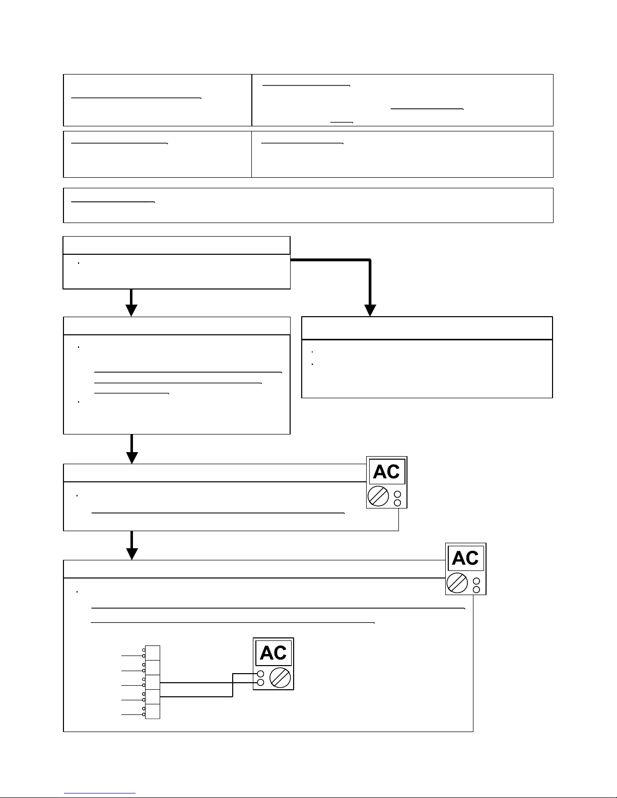
Trouble shooting 12
INDOOR UNIT Error Method:
Detective Actuators:
Detective details:
Forecast of Cause:
Check Point 2 : Check Connection
OK
Indicate or Display:Indicate or Display:
ERROR CODE : E : 13
Check Point 3 : Check the voltage of power supply
Check Point 1-1 : Reset the power
YESYES
NO
Check Point 1-2:
N
L
3
2
1
WHITE
BLACK
RED
WHITE
BLACK
+
-
OK
Check Point 4 : Check Serial Signal (Forward Transfer Signal)
Check Serial Signal (Forward Transfer Signal)
Outdoor Communication Signal Error
(Forward Transfer Signal Error)
Indoor Unit Controller PCB Circuit
1. Connection failure 2. External cause 3. Controller PCB failure
Does Error indication reappear?
Check external cause such as noise
Check the complete insulation of the grounding.
Check if there is any equipment that causes harmonic wave
near the power cable (Neon light bulb or any electronic
equipment which causes harmonic wave).
Check the voltage of power supply
>> Check if AC198 - 264V appears at Outdoor Unit Terminal L - N.
>> Check if Indicated value swings between AC70V and AC130V at Outdoor Unit Terminal 2 - 3.
Check any loose or removed connection line of
Indoor unit and Outdoor unit.
>> If there is an abnormal condition, correct it by
referring to Installation Manual or Data &
Technical Manual.
Check connection between Indoor Unit Controller PCB
and Filter PCB.
(If there is loose connector or open cable)
>> If it is abnormal, Controller PCB is failure. >> Replace Controller PCB
07-14
When the outdoor unit cannot receive the serial signal from Indoor unit
more than 10seconds.
Outdoor Unit (AR*A12L- 24L) : No indication
(AR*A36L/ 45L) : LED 4 times blink
Page 74
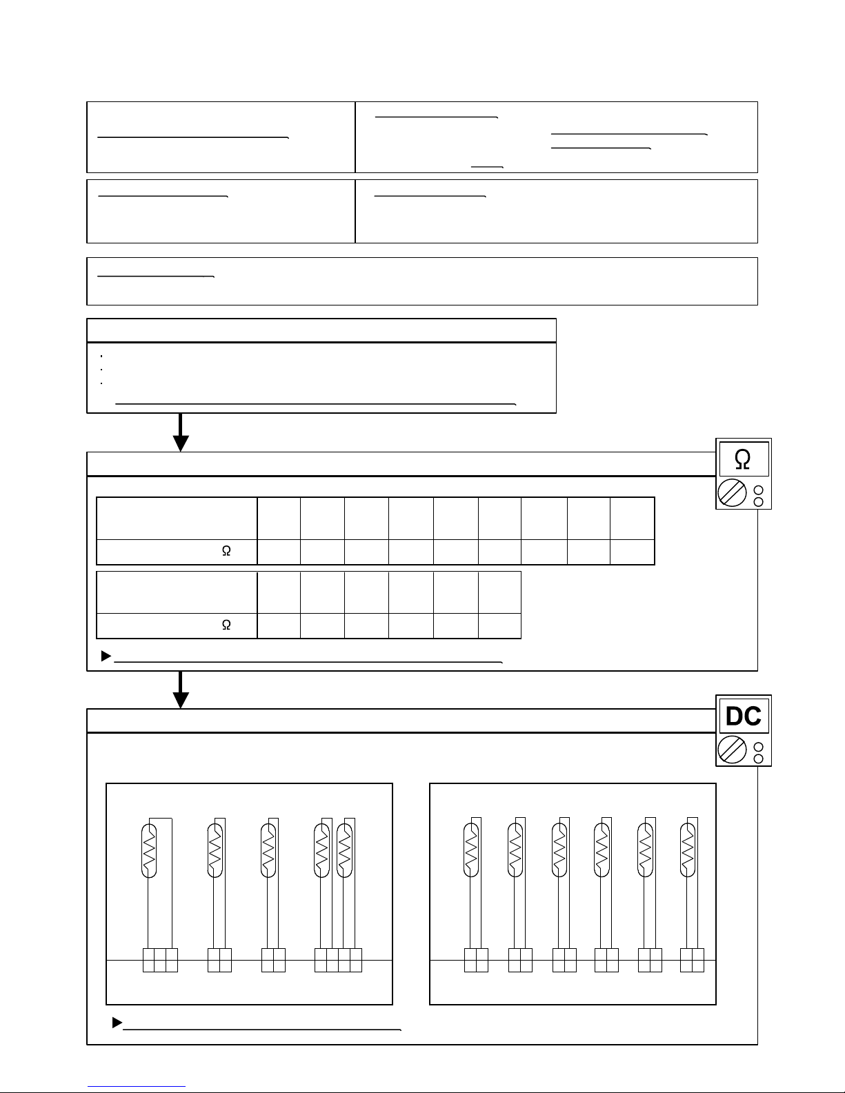
Trouble shooting 13
OUTDOOR UNIT Error Method:
Indicate or Display:
ERROR CODE : E : 15
Detective Actuators:
Detective details:
Forecast of Cause :
Check Point 2 :
Check Point 3 :
OKOK
OKOK
Compressor Temperature Sensor Error
Outdoor Unit Main PCB Circuit
Compressor Temperature Thermistor
When Compressor Temperature Thermistor open or short-circuit is
detected at power ON or while running the compressor.
1. Connector connection failure 2. Thermistor failure 3. Main PCB failure
Check Point 1 : Check connection of Connector
Check if connector is removed.
Check erroneous connection.
Check if thermistor cable is open.
>>Upon correcting the removed connector or mis-wiring, reset the power.
Check Point 2 : Remove connector and check Thermistor resistance value
Thermistor Characteristics (Rough value)
If Thermistor is either open or shorted, replace it and reset the power.
Check Point 3 : Check voltage of Main PCB (DC5.0V)
Make sure circuit diagram of outdoor unit and check terminal voltage at Thermistor (DC5.0V)
If the voltage does not appear, replace Main PCB.
07-15
For AR*A12L- 24L For AR*A36L/ 45L
THERMISTOR
(PIPE OUT)
THERMISTOR
(DISCHARGE)
THERMISTOR
(COMPRESSOR)
THERMISTOR
(PIPE MID)
THERMISTOR
(OUTDOOR)
BLACK
CN70 CN72 CN73 CN71
CN24 CN21 CN22 CN23 CN26 CN25
2 13 2 1 4 3 2 12 1
BROWN
BROWN
BLACK
THERMISTOR
(PIPE MID)
THERMISTOR
(DISCHARGE)
THERMISTOR
(PIPE OUT)
THERMISTOR
(OUTDOOR)
THERMISTOR
(COMPRESSOR)
THERMISTOR
(HEAT SINK)
BLACK
BBROWN
BLACK
BLUE
BROWN
BLACK
BLACK
2 13 2 1 4 3 2 12 1
1 2
1 2
1 2
1 2
1 2
1 2
1 2
1 2
1 2
1 2
1 2
1 2
Outdoor Unit (AR*A12L- 24L) : LED 0.1sec ON/ 0.1sec OFF
(AR*A36L/ 45L) : LED 7 times blink
17.826.3
20°C
40.062.679.1101130169Resistance Value (k )
15°C10°C5°C0°C
Temperature
12.3
30°C
50°C40°C
60°C
1.222.003.434.606.278.70Resistance Value (k )
140°C120°C100°C
90°C80°C70°C
Temperature
Page 75
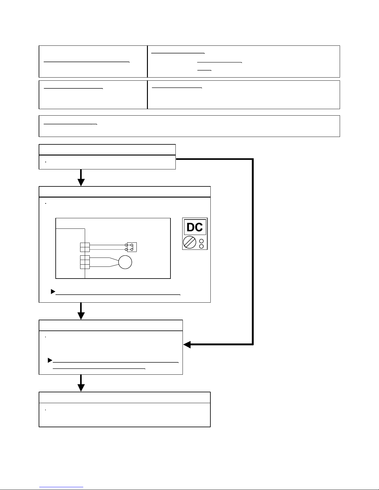
Trouble shooting 14
INDOOR UNIT
OUTDOOR UNIT Error Method:
Indicate or Display:
ERROR CODE : E : 16
Detective Actuators:
Detective details:
Forecast of Cause :
Check Point 3 : Check Point 2 : Check voltage of Main PCB (DC5.0V)
HIGH PRESSURE SW
BLACK
BLACK
RED
RED
CN37
121
2
1
2
3
1
2
3
4WV
OK
Check Point 1 : Reset Power Supply and operate
Check Point 3 : Check Pressure Switch
YES
NONO
OK
Pressure Switch Error
Outdoor Unit Main PCB Circuit
Pressure Switch
1. Connector connection failure 2. Pressure Switch failure 3. Main PCB failure
When pressure switch open is detected in 10 seconds
after the power is turned on.
Does abnormal LED indication show again?
Make sure circuit diagram of outdoor unit and check terminal voltage
at Pressure Switch. (DC5.0V)
If the voltage does not appear, replace Main PCB.
Check if connector is loose or cable is open.
>> If no abnormal connection is found,
replace Pressure Switch.
After replacing Pressure Switch, check operating
condition and pressure in operation.
Check Point 4 : Check High Pressure Protection on cooling
Check Excessive high pressure protection on cooling.
(Refer to Trouble shooting 22)
07-16
Outdoor Unit : LED 9 times blink
( For AR*A36L/ 45L )
Page 76

Trouble shooting 15
OUTDOOR UNIT Error Method:
Detective Actuators:
Detective details:
Forecast of Cause :
Check Point 3 : Check Outdoor Fan
OK
OK
Indicate or Display:
ERROR CODE : E : 17
Check Point 5 : Replace Main PCB
OKOK
OKOK
Check Point 1 : Check connections of Outdoor Unit Electrical Components
IPM error (Permanent Stop)
Outdoor Unit Main PCB Circuit
Compressor
1. Defective connection of electric components 2. Outdoor Fan Operation failure
3. Outdoor Heat Exchanger clogged 4. Compressor failure 5. Main PCB failure
Check if connector is removed.
Check if the terminal connection is loose.
Check erroneous connection.
Check if cable is open.
>>Upon correcting the removed connector or mis-wiring, reset the power.
Check Point 2 : Check Outdoor Fan, Heat Exchanger
Is there anything obstructing the air distribution circuit?
Is there any clogging of Outdoor Heat Exchanger?
Is the Fan rotating by hand when operation is off ?
>> If the Fan Motor is locked, replace it.
Check Outdoor Fan Motor. (Refer to Trouble shooting 19)
>> If the Fan Motor is failure, replace it.
Check Point 4 : Check Compressor
(PARTS INFORMATION 2)
Check Compressor.
If Check Point 1 4 do not improve the symptom, change Main PCB.
When more than normal operating current to IPM in Main PCB flows,
the compressor stops.
After the compressor restarts, if the same operation is repeated within 40sec,
the compressor stops again.
If and repeats 5 times, the compressor stops permanently.
07-17
Outdoor Unit (AR*A12L- 24L) : LED 0.5sec ON/ 0.5sec OFF
(AR*A36L/ 45L) : LED 12 times blink
Page 77
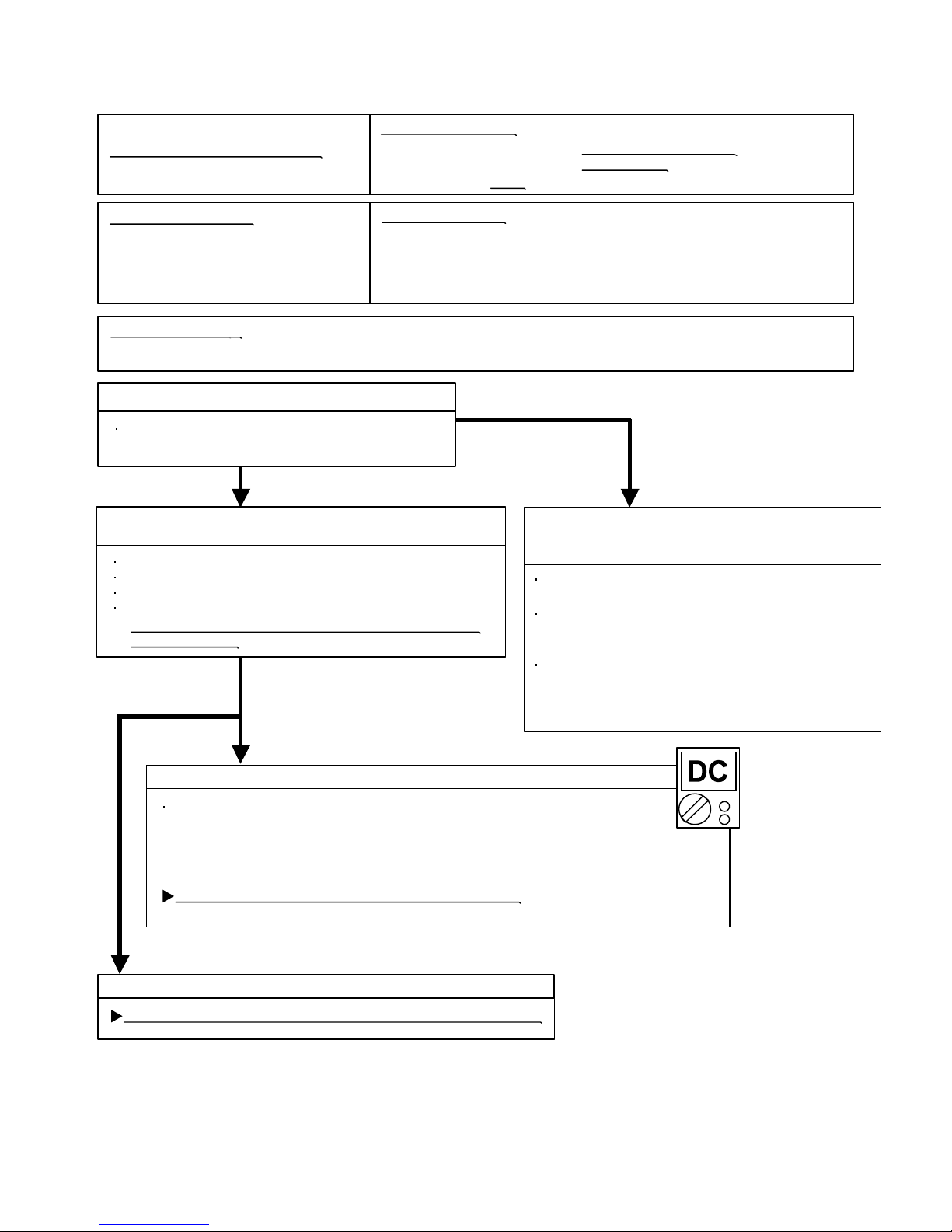
Trouble shooting 16
OUTDOOR UNIT Error Method:
Detective Actuators:
Detective details:
Forecast of Cause :
Check Point 3 : Check Filter PCB and Main PCB
Check Point 4 : Replace Main PCB
YES
NO
OK
Indicate or Display:
ERROR CODE : E : 18
CT error
Outdoor Unit Main PCB Circuit
Outdoor Unit Filter PCB Circuit
(Input current sensor unit)
Check Point 2 :
Check connections of Outdoor Unit Electrical Components
Check if connector is removed.
Check if the terminal connection is loose.
Check erroneous connection.
Check if cable is open.
>>Upon correcting the removed connector or mis-wiring,
reset the power.
Check Point 1-2 :
Check external cause at Indoor and Outdoor
(Voltage drop or Noise)
1. Defective connection of electric components 2. External cause 3. Filter PCB failure 4. Main PCB failure
Instant drop : Check if there is a large load electric
apparatus in the same circuit.
Momentary power failure : Check if there is a defective
contact or leak current in the
power supply circuit.
Noise : Check if there is any equipment causing harmonic
wave near electric line.(Neon bulb or electric
equipment that may cause harmonic wave)
Check the complete insulation of grounding.
Check Point 1-1 : Reset Power Supply and operate
Does Error indication show again?
When Input Current Sensor has detected 0A, while Inverter Compressor is
operating at higher than 56Hz(for AR*A12L-24L) or 50Hz(for AR*A36L/ 45L),
after 1minute upon starting the Compressor.
(Except during the defrost operation)
07-18
Check DC voltage of CN1 (between 2 (Brown) and 3 (Red)) on Filter PCB.
>> After 40seconds upon starting the Compressor,
If it is higher than 0.2V, Main PCB is failure. (Filter PCB is normal) >> Replace Main PCB
>> If it is lower than 0.2V, Filter PCB is failure. >> Replace Filter PCB
If it does not improve the symptom, change Main PCB.
AR*A12L- 24L
If Check Point 1, 2 do not improve the symptom, change Main PCB.
Outdoor Unit (AR*A12L- 24L) : LED 2sec ON/ 2sec OFF
(AR*A36L/ 45L) : No indication
Page 78
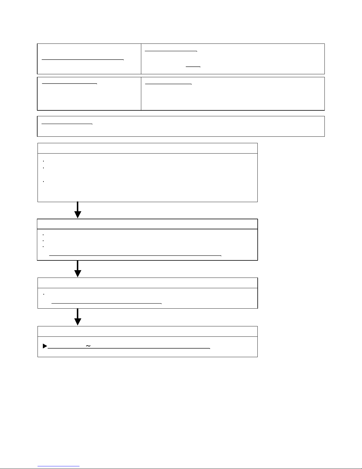
Trouble shooting 17
INDOOR UNIT
OUTDOOR UNIT Error Method:
Indicate or Display:
Outdoor Unit : No indication
ERROR CODE : E : 19
Detective Actuators:
Detective details:
Forecast of Cause :
Check Point 3 : Check Active Filter Module
OKOK
OKOK
OKOK
Active Filter Module (AFM) error
Outdoor Unit Main PCB Circuit
Active Filter Module
1. External cause 2. Connector connection failure 3. Active Filter Module failure 4. Main PCB failure
Check Point 2 : Check connection of Connector
Check if connector is removed.
Check erroneous connection.
Check if cable is open.
>>Upon correcting the removed connector or mis-wiring, reset the power.
Check Active Filter Module. (PARTS INFORMATION 3)
>>If Active Filter Module is abnormal, replace it.
Check Point 4 : Replace Main PCB
If Check Point 1 3 do not improve the symptom, change Main PCB.
Check Point 1 : Check external cause at Indoor and Outdoor (Voltage drop or Noise)
Instant drop : Check if there is a large load electric apparatus in the same circuit.
Momentary power failure : Check if there is a defective contact or leak current
in the power supply circuit.
Noise : Check if there is any equipment causing harmonic wave near electric line.
(Neon bulb or electric equipment that may cause harmonic wave)
Check the complete insulation of grounding.
07-19
When inverter input DC voltage is higher than 467V or
lower than 237V.
When a momentary power cut off occurred on low voltage.
( For AR*A36L/ 45L )
Page 79
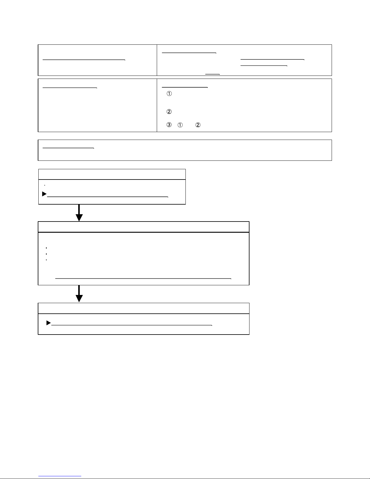
Trouble shooting 18
OUTDOOR UNIT Error Method:
Detective Actuators:
Detective details:
Forecast of Cause :
Check Point 2 : Check connection of around the Compressor components
OKOK
OKOK
Indicate or Display:
ERROR CODE : E : 1A
Check Point 3: Replace Main PCB
Outdoor Unit Main PCB Circuit
Compressor
Compressor rotor location cannot detect
(Permanent Stop)
1. Defective connection of electric components 2. Main PCB failure 3. Compressor failure
If Check Point 1,2 do not improve the symptom, change Main PCB.
Check if connector is removed.
Check erroneous connection.
Check if cable is open.
>>Upon correcting the removed connector or mis-wiring, reset the power.
(Refer to PARTS INFORMATION 2)
For Compressor Terminal, Main PCB
While running the compressor, if the detected rotor location is out of
phase with actual rotor location more than 90 degrees,
the compressor stops.
After the compressor restarts, if the same operation is repeated
within 40sec, the compressor stops again.
If and repeats 5 times, the compressor stops permanently.
07-20
Check Point 1 : Check Noise from Compressor
Turn on Power and check operation noise.
If an abnormal noise show, replace Compressor.
Outdoor Unit (AR*A12L- 24L) : LED 0.1sec ON/ 2sec OFF
(AR*A36L/ 45L) : LED 13 times blink
Page 80

Trouble shooting 19
OUTDOOR UNIT Error Method:
Detective Actuators:
Detective details:
Forecast of Cause:
Check Point 2 : Check ambient temp. around motor
OK
OK
Indicate or Display:
ERROR CODE : E : 1b
Outdoor Unit Fan Motor Error
Outdoor Unit Main PCB Circuit
Outdoor Fan Motor
1. Fan rotation failure 2. Motor protection by surrounding temperature rise 3. Main PCB failure
Check Point 1 : Check rotation of Fan
Rotate the fan by hand when operation is off.
(Check if fan is caught, dropped off or locked motor)
>>If Fan or Bearing is abnormal, replace it.
Check excessively high temperature around the motor.
(If there is any surrounding equipment that causes heat)
>>Upon the temperature coming down, restart operation.
Check Point 3 : Check Output Voltage of Main PCB
Check outdoor unit circuit diagram and the voltage. (Measure at Main PCB side connector)
If the voltage is not correct, replace Main PCB.
When outdoor fan rotation speed is less than 100rpm in 20 seconds
after fan motor starts, fan motor stops.
After fan motor restarts, if the same operation within 60sec is repeated
3 times in a row, compressor and fan motor stops.
If and repeats 5 times in a row, compressor and fan motor stops
permanently.
AR*A12L- 24L AR*A36L/ 45L
Read wire DC voltage
Red - Black
White - Black
150 390V
15 1.5V
〜
Read wire DC voltage
Red - Black
White - Black
300 400V
15 1.5V
〜
07-21
CN800
CN801
1
2
3
4
5
6
7
1
2
3
4
5
6
7
BLACK
WHITE
YELLOW
BROWN
RED
BLACK
WHITE
YELLOW
BROWN
RED
FM
FM
FAN MOTOR 1
FAN MOTOR 2
CN801
1
2
3
4
5
6
BLACK
WHITE
YELLOW
BROWN
RED
FM
FAN MOTOR
Outdoor Unit (AR*A12L- 24L) : LED 5sec ON/ 5sec OFF
(AR*A36L/ 45L) : LED 15 times blink (Upper fan)
LED 16 times blink (Lower fan)
Page 81

07-22
Trouble shooting 20
INDOOR UNIT
OUTDOOR UNIT Error Method:
Indicate or Display:
Detective Actuators:
Detective details:
Forecast of Cause :
Outdoor unit computer
communication error
Outdoor Unit Main PCB Circuit
When it cannot receive an effective signal for 10sec between
the Main CPU and Sub CPU in outdoor unit.
1. Main PCB failure
Check Point 1 : Replace Main PCB
Change Main PCB.
Outdoor Unit : No indication
ERROR CODE : E : 1c
Outdoor Unit : No indication
ERROR CODE : E : 20
Trouble shooting 21
INDOOR UNIT
INDOOR UNIT Error Method:
Indicate or Display:
Detective Actuators:
Detective details:
Forecast of Cause :
OKOK
Indoor manual auto switch error
Indoor Unit Controller PCB Circuit
Forced auto switch
When the Forced auto switch becomes ON for 30 consecutive seconds.
1. Forced auto switch failure 2.Controller PCB failure
Check Point 1 : Check the Forced auto switch
Check if Forced auto switch is kept pressed.
Check Point 2 : Replace Controller PCB
If Check Point 1 do not improve the symptom, change Controller PCB.
Check ON/OFF switching operation by using a meter.
>>If Forced auto switch is detective, replace it.
Page 82
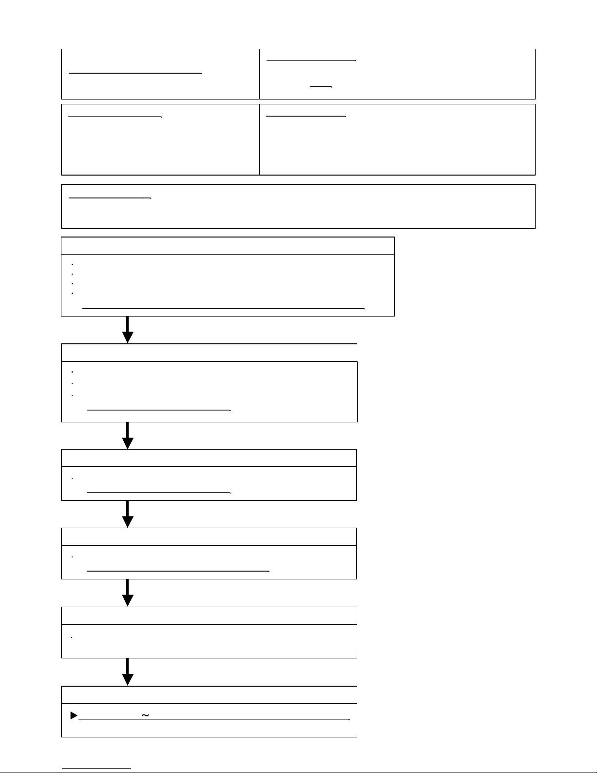
Trouble shooting 22
OUTDOOR UNIT Error Method:
Detective Actuators:
Detective details:
Forecast of Cause :
Check Point 3 : Check Outdoor Fan
OK
OK
Indicate or Display:
OKOK
OKOK
Check Point 1 : Check connections of Outdoor Unit Electrical Components
Excessive high pressure protection
on cooling
1. Defective connection of electric components 2. Outdoor Fan Operation failure
3. Outdoor Heat Exchanger clogged 4. Thermistor failure 5. EEV failure 6. Main PCB failure
Check if connector is removed.
Check if the terminal connection is loose.
Check erroneous connection.
Check if cable is open.
>>Upon correcting the removed connector or mis-wiring, reset the power.
Check Point 2 : Check Outdoor Fan, Heat Exchanger
Is there anything obstructing the air distribution circuit?
Is there any clogging of Outdoor Heat Exchanger?
Is the Fan rotating by hand when operation is off ?
>> If the Fan Motor is locked, replace it.
Check Outdoor Fan Motor. (Refer to Trouble shooting 19)
>> If the Fan Motor is failure, replace it.
Check Thermistor (middle). (Refer to Trouble shooting 26)
>> If the Thermistor (middle) is failure, replace it.
Check Point 5 : Check Electronic Expansion Valve
Check Point 4 : Check Thermistor (middle)
(PARTS INFORMATION 4)
Check EEV.
Excessive high pressure protection on cooling mode has been
activated.
07-23
Check Point 6 : Replace Main PCB
OKOK
If Check Point 1 5 do not improve the symptom, change Main PCB.
Outdoor Unit : No indication
ERROR CODE : E : 24
Outdoor Unit Main PCB Circuit
Outdoor Fan Motor
Heat Exchanger Temp. Thermistor (Middle)
Outdoor unit Electronic Expansion Valve
Page 83
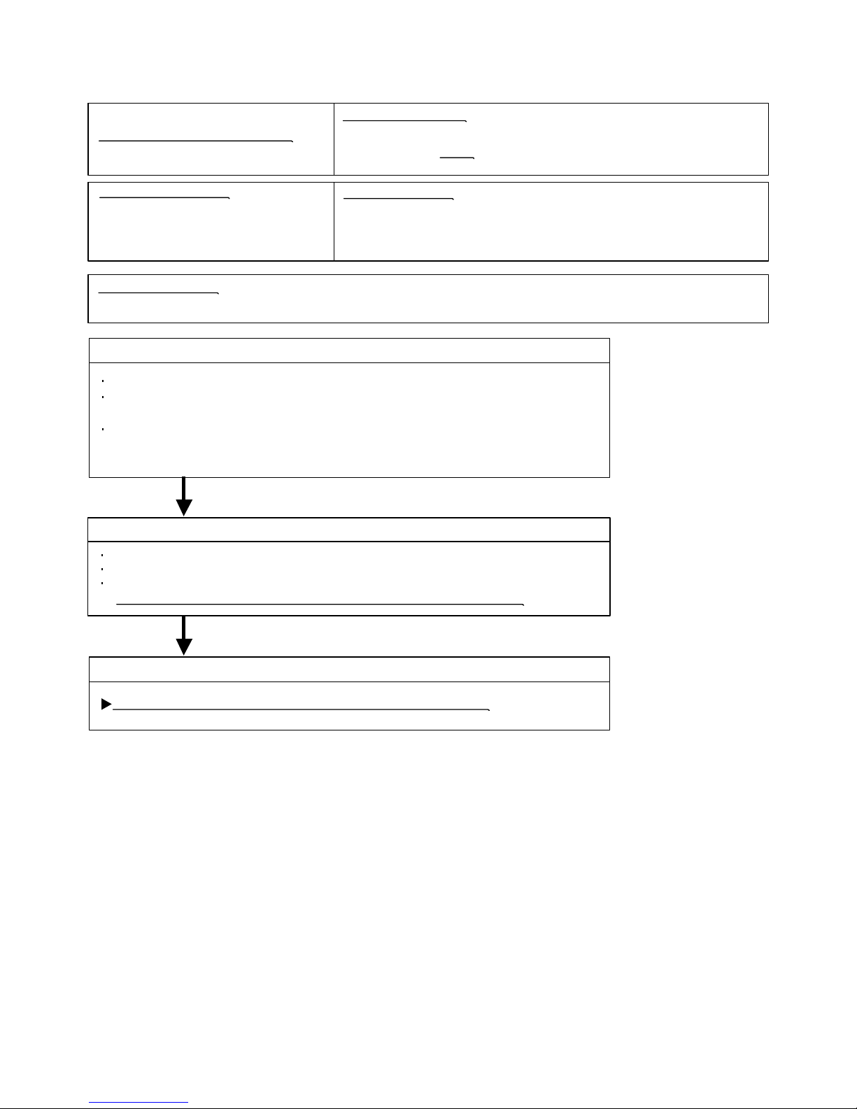
Trouble shooting 23
INDOOR UNIT
OUTDOOR UNIT Error Method:
Indicate or Display:
Outdoor Unit : No indication
ERROR CODE : E : 25
Detective Actuators:
Detective details:
Forecast of Cause :
OKOK
OKOK
PFC circuit error
Outdoor Unit Main PCB Circuit
1. External cause 2. Connector connection failure 3. Main PCB failure
Check Point 2 : Check connection of Connector
Check if connector is removed.
Check erroneous connection.
Check if cable is open.
>>Upon correcting the removed connector or mis-wiring, reset the power.
Check Point 3 : Replace Main PCB
If Check Point 1, 2 do not improve the symptom, change Main PCB.
Check Point 1 : Check external cause at Indoor and Outdoor (Voltage drop or Noise)
Instant drop : Check if there is a large load electric apparatus in the same circuit.
Momentary power failure : Check if there is a defective contact or leak current
in the power supply circuit.
Noise : Check if there is any equipment causing harmonic wave near electric line.
(Neon bulb or electric equipment that may cause harmonic wave)
Check the complete insulation of grounding.
07-24
When inverter output DC voltage is higher than 415V for over 3 seconds,
the compressor stops.
If the same operation is repeated 5 times, the compressor stops permanently.
( For AR*A12L - 24L )
Page 84
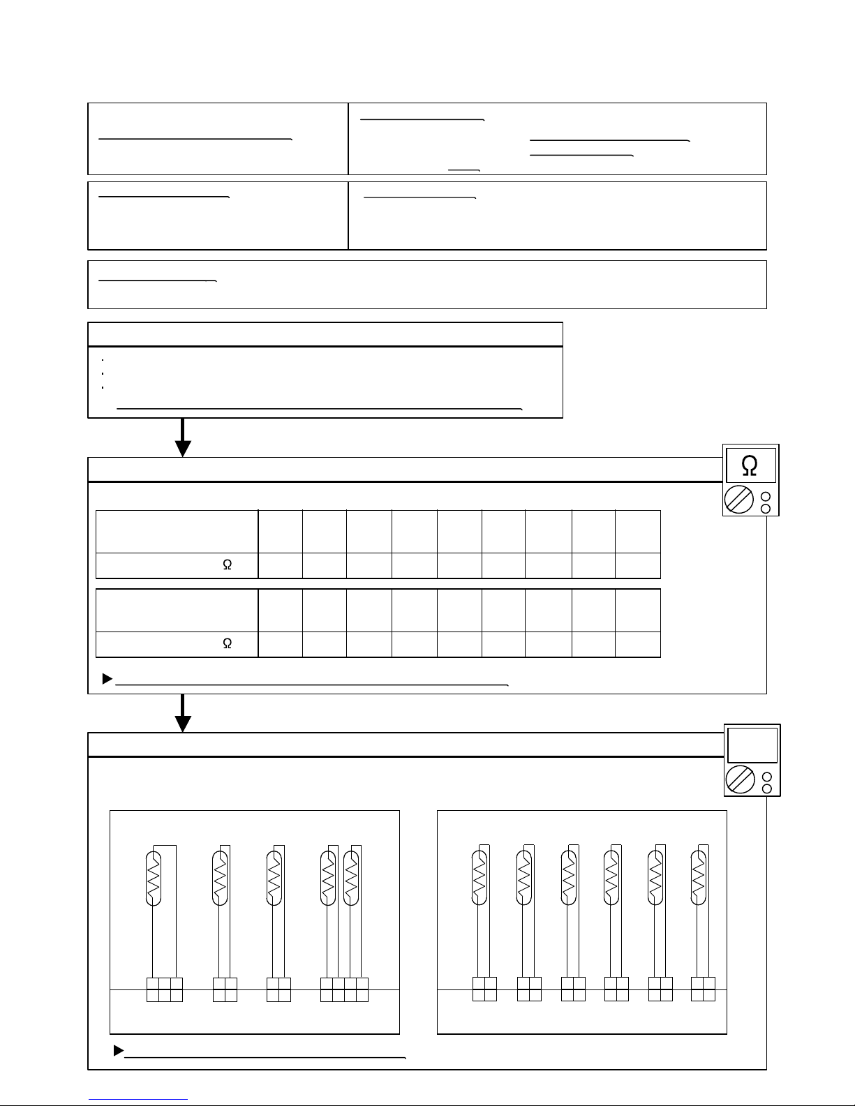
Trouble shooting 26
OUTDOOR UNIT Error Method:
Indicate or Display:
Outdoor Unit (AR*A12L- 24L) : LED 0.1sec ON/ 0.1sec OFF
(AR*A36L/ 45L) : LED 5 times blink
For AR*A12L- 24L For AR*A36L/ 45L
ERROR CODE : E : 29
Detective Actuators:
Detective details:
Forecast of Cause :
Check Point 2 :
Check Point 3 :
4.77
25°C
5.98
20°C
7.569.6312.416.121.027.8Resistance Value (k )
15°C10°C5°C0°C-5°C-10°C
Temperature
OKOK
OKOK
DC
3.84
30°C
0.446
90°C
0.606
80°C
0.8401.191.712.082.533.11Resistance Value (k )
70°C60°C50°C45°C40°C35°C
Temperature
0.333
100°C
THERMISTOR
(PIPE OUT)
THERMISTOR
(DISCHARGE)
THERMISTOR
(COMPRESSOR)
THERMISTOR
(PIPE MID)
THERMISTOR
(OUTDOOR)
BLACK
CN70 CN72 CN73 CN71
CN24 CN21 CN22 CN23 CN26 CN25
2 13 2 1 4 3 2 12 1
BROWN
BROWN
BLACK
THERMISTOR
(PIPE MID)
THERMISTOR
(DISCHARGE)
THERMISTOR
(PIPE OUT)
THERMISTOR
(OUTDOOR)
THERMISTOR
(COMPRESSOR)
THERMISTOR
(HEAT SINK)
BLACK
BBROWN
BLACK
BLUE
BROWN
BLACK
BLACK
Outdoor Heat Exchanger Temperature
Sensor (Middle) Error
Outdoor Unit Main PCB Circuit
Heat Exchanger Temperature
Thermistor (Middle)
When Heat Exchanger Temperature Thermistor (Middle) open or
short-circuit is detected at power ON or while running the compressor.
1. Connector connection failure 2.Thermistor failure 3. Main PCB failure
Check Point 1 : Check connection of Connector
Check if connector is removed.
Check erroneous connection.
Check if thermistor cable is open.
>>Upon correcting the removed connector or mis-wiring, reset the power.
Check Point 2 : Remove connector and check Thermistor resistance value
Thermistor Characteristics (Approx. value)
If Thermistor is either open or shorted, replace it and reset the power.
Check Point 3 : Check voltage of Main PCB (DC5.0V)
Make sure circuit diagram of outdoor unit and check terminal voltage at Thermistor (DC5.0V)
If the voltage does not appear, replace Main PCB.
07-25
2 13 2 1 4 3 2 12 1
1 2
1 2
1 2
1 2
1 2
1 2
1 2
1 2
1 2
1 2
1 2
1 2
Page 85

Trouble shooting 27
INDOOR UNIT
OUTDOOR UNIT Error Method:
Indicate or Display:
ERROR CODE : E : 2b
Detective Actuators:
Detective details:
Forecast of Cause :
Compressor temperature error
Outdoor Unit Main PCB Circuit
Compressor Temperature Thermistor
07-26
Outdoor Unit (AR*A12L- 24L) : LED 2sec ON/ 5sec OFF
(AR*A36L/ 45L) : LED 10 times blink
When the compressor temperature becomes higher than 110°C,
the compressor stops.
After the compressor restarts, if the same operation is repeated,
the compressor stops permanently.
Check Point 1 : Check if Gas Valve is open
If it is not open, open it and check the operation.
Check Point 3 : Check if gas leak or less gas
Measure Gas pressure, if there is a leak, correct it.
>>If recharging refrigerant, make sure to perform
vacuuming and recharge the specified amount.
Check Point 5 : Check Outdoor FAN, Heat Exchanger
Is there anything obstructing the air distribution circuit?
Is there any clogging of Outdoor Heat Exchanger?
Is the Fan rotating? (Check by hand and if it is locked, replace the motor)
Check Outdoor Fan Motor.
>>If the Fan Motor is defective, replace it.
Check Point 4 : Check Compressor Thermistor
Isn’t it fallen off the holder?
Is there a cable pinched?
>> Check characteristics of thermistor (Refer to Trouble shooting 13),
If defective, replace the thermistor
Check Point 2 : Check EEV and Strainer
Are EEV and Strainer open?
(Refer to PARTS INFORMATION 4)
>>If EEV or Strainer is defective, replace it.
OK OK
OK
OK
OK
OK
MPa MPa
1. Valve is close 2. EEV failure 3. Gas Leak, less 4. Compressor Thermistor failure
5. Outdoor Fan Operation failure 6. Outdoor Heat Exchanger clogged
< Cooling mode >
< Heating mode >
Check Point 1 : Check if LIquid Valve is open
If it is not open, open it and check the operation.
Check Point 2 : Check EEV and Strainer
Are EEV and Strainer open?
(Refer to PARTS INFORMATION 4)
>>If EEV or Strainer is defective, replace it.
Page 86
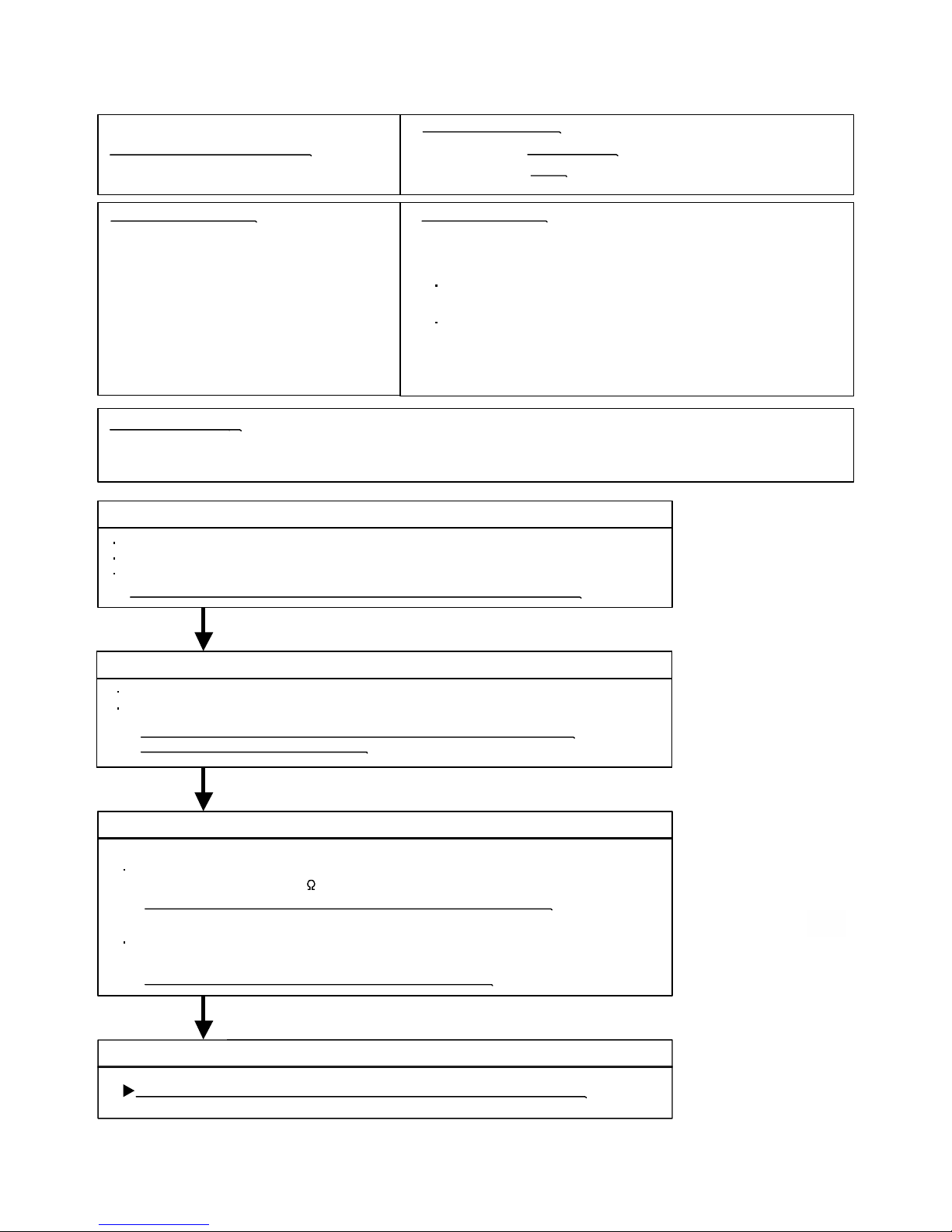
Trouble shooting 28
INDOOR UNIT Error Method:
Indicate or Display:
ERROR CODE : E : 2c
Detective Actuators:
Detective details:
Forecast of Cause :
OKOK
OKOK
4-way valve error
Indoor Unit Controller PCB Circuit
Heat Exchanger Temperature Thermistor
Room Temperature Thermistor
4-way valve
When the indoor heat exchanger temperature is compared with
the room temperature, and either following condition is detected
continuously two times, the compressor stops.
1. Connector connection failure 2. Thermistor failure 3. Coil failure 4. 4-way valve failure
5. Controller PCB failure
Check Point 1 : Check connection of Connector
Check if connector is removed.
Check erroneous connection.
Check if thermistor cable is open.
>>Upon correcting the removed connector or mis-wiring, reset the power.
Check Point 3 : Check the solenoid coil and 4-way valve
Remove CN30 from PCB and check the resistance value of coil.
Resistance value is about 1.4k
>>If it is Open or abnormal resistance value, replace Solenoid Coil.
07-27
Outdoor Unit : No indication
Cooling or Dry operation
[Indoor heat exchanger temp.] - [Room temp.] > 10degC
Heating operation
[indoor heat exchanger temp.] - [room temp.] < -10degC
If the same operation is repeated 5 times,
the compressor stops permanently.
[ Solenoid coil ]
Check each piping temperature,
and the location of the valve by the temperature difference.
>>If the value location is not proper, replace 4-way valve.
[ 4-way valve ]
OKOK
Check Point 4 : Replace Controller PCB
If Check Point 1- 3 do not improve the symptom, replace Controller PCB.
Check Point 2 : Check Heat exchanger temp. thermistor and Room temp. thermistor
Isn’t it fallen off the holder?
Is there a cable pinched?
>> Check characteristics of thermistor (Refer to Trouble shooting 3, 4),
If defective, replace the thermistor
Page 87

Trouble shooting 29
OUTDOOR UNIT Error Method:
Indicate or Display:
Outdoor Unit : LED 8 times blink
For AR*A36L/ 45L
ERROR CODE : No indication
Detective Actuators:
Detective details:
Forecast of Cause :
Check Point 2 :
Check Point 3 :
4.77
25°C
5.98
20°C
7.569.6312.416.121.027.8Resistance Value (k )
15°C10°C5°C0°C-5°C-10°C
Temperature
OKOK
OKOK
DC
3.84
30°C
0.446
90°C
0.606
80°C
0.8401.191.712.082.533.11Resistance Value (k )
70°C60°C50°C45°C40°C35°C
Temperature
0.333
100°C
CN24 CN21 CN22 CN23 CN26 CN25
THERMISTOR
(PIPE MID)
THERMISTOR
(DISCHARGE)
THERMISTOR
(PIPE OUT)
THERMISTOR
(OUTDOOR)
THERMISTOR
(COMPRESSOR)
THERMISTOR
(HEAT SINK)
BLACK
BBROWN
BLACK
BLUE
BROWN
BLACK
Heat Sink Temperature Sensor Error
Outdoor Unit Main PCB Circuit
Heat Sink Temperature Thermistor
When Heat Sink Temperature Thermistor open or
short-circuit is detected at power ON or while running the compressor.
1. Connector connection failure 2.Thermistor failure 3. Main PCB failure
Check Point 1 : Check connection of Connector
Check if connector is removed.
Check erroneous connection.
Check if thermistor cable is open.
>>Upon correcting the removed connector or mis-wiring, reset the power.
Check Point 2 : Remove connector and check Thermistor resistance value
Thermistor Characteristics (Approx. value)
If Thermistor is either open or shorted, replace it and reset the power.
Check Point 3 : Check voltage of Main PCB (DC5.0V)
Make sure circuit diagram of outdoor unit and check terminal voltage at Thermistor (DC5.0V)
If the voltage does not appear, replace Main PCB.
07-28
1 2
1 2
1 2
1 2
1 2
1 2
1 2
1 2
1 2
1 2
1 2
1 2
( For AR*A36L/ 45L )
Page 88

Trouble shooting 30
OUTDOOR UNIT Error Method:
Detective Actuators:
Detective details:
Forecast of Cause :
Indicate or Display:
Compressor Start-up error
(Permanent Stop)
On start-up the compressor, when detected rotor position is out of phase
with actual rotor position more than 90 degrees,the compressor stops.
After the compressor restarts, if the same operation is repeated
within 40sec, the compressor stops again.
If and repeats 5 times, the compressor stops permanently.
Outdoor Unit Main PCB Circuit
Compressor
1. Defective connection of electric components 2. Main PCB failure 3. Compressor failure
Check Point 2 : Check connection of around the Compressor components
OKOK
OKOK
Check Point 3 : Replace Main PCB
If Check Point 1,2 do not improve the symptom, replace Main PCB.
Check if connector is removed.
Check erroneous connection.
Check if cable is open.
>>Upon correcting the removed connector or mis-wiring, reset the power.
(Refer to PARTS INFORMATION 2)
For Compressor Terminal, Main PCB
07-29
Check Point 1 : Check Noise from Compressor
Turn on Power and check operation noise.
If an abnormal noise show, replace Compressor.
ERROR CODE : E : 1A
Outdoor Unit (AR*A12L- 24L) : LED 0.1sec ON/ 2sec OFF
(AR*A36L/ 45L) : LED 14 times blink
Page 89
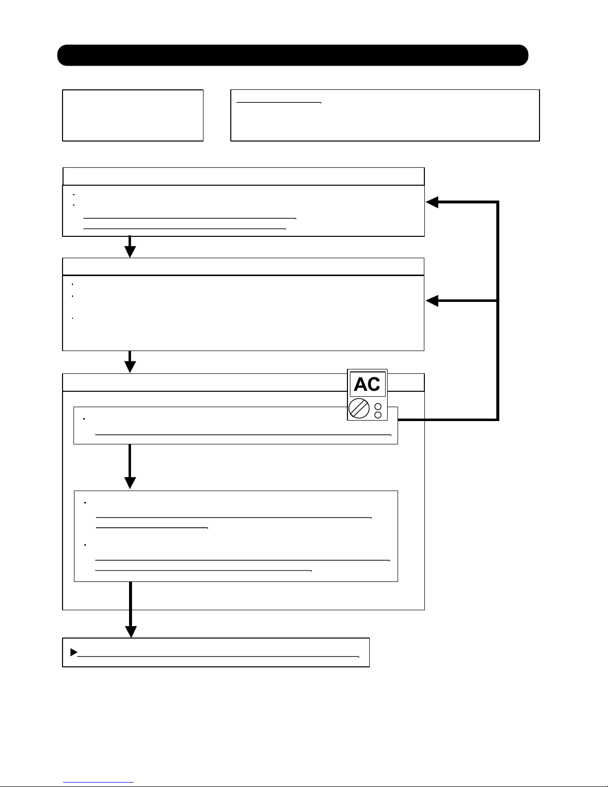
Trouble shooting 31
Forecast of Cause:
YESYES
NO
OKOK
OKOK
OKOK
Indoor Unit - No Power
1. Power Supply failure 2. External cause
3. Electrical Components defective
Check Point 1 : Check Installation Condition
Isn’t the breaker down?
Check loose or removed connection cable.
>>If abnormal condition is found, correct it by referring
to Installation Manual or Data & Technical Manual.
Check Point 2 : Check external cause at Indoor and Outdoor (Voltage drop or Noise)
Instant drop ----- Check if there is a large load electric apparatus in the same circuit.
Momentary power failure ----- Check if there is a defective contact or leak current in
the power supply circuit.
Noise ----- Check if there is any equipment causing harmonic wave near electric line.
(Neon bulb or electric equipment that may cause harmonic wave)
Check the complete insulation of grounding.
Check Point 3 : Check Electrical Components
Check Voltage of power supply.
>> Check AC198 - 264V appears at Indoor Unit Terminal 1 - 2 (Power Supply).
Check Fuse in Filter PCB.
>> If Fuse is open, check if the wiring between Terminal and Filter PCB
is loose, and replace Fuse.
Check Varistor in Filter PCB.
>> If Varistor is defective, there is a possibility of an abnormal power supply.
Check the correct power supply and replace Varistor.
If the symptom does not change by above Check3, replace Filter PCB.
07-30
7-3 TROUBLE SHOOTING WITH NO ERROR CODE
Page 90
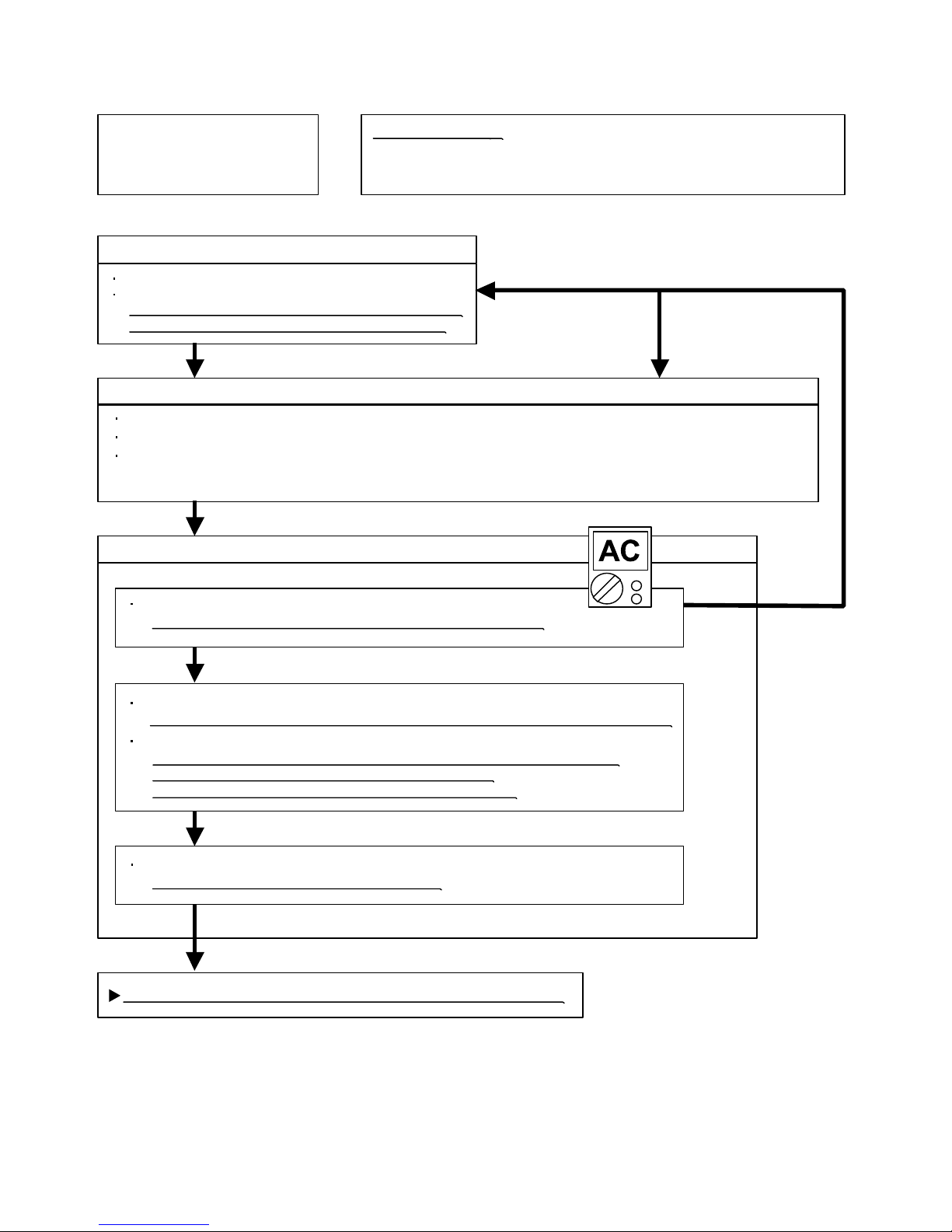
Trouble shooting 32
Forecast of Cause:
Check Point 3 : Check Electrical Components
OKOK
OKOK
YESYES
OK
NO
Check Point 1 : Check Installation Condition
Outdoor Unit - No Power
1. Power Supply failure 2. External cause
3. Electrical Components defective
Isn’t the breaker down?
Check loose or removed connection cable.
>>If abnormal condition is found, correct it by referring
to Installation Manual or Data & Technical Manual.
Check Point 2 : Check external cause at Indoor and Outdoor (Voltage drop or Noise)
Instant drop ----- Check if there is a large load electric apparatus in the same circuit.
Momentary power failure ----- Check if there is a defective contact or leak current in the power supply circuit.
Noise ----- Check if there is any equipment causing harmonic wave near electric line.
(Neon bulb or electric equipment that may cause harmonic wave)
Check the complete insulation of grounding.
Check the voltage of power supply.
>> Check if AC198 - 264V appears at Outdoor Unit Terminal L - N.
YESYES
Check Fuse in Main PCB.
>> If Fuse is open, check loose terminal or removed connector (CN1) , and replace Fuse.
Check Varistor in Main PCB.
>> If Varistor is defective, there is a possibility of an abnormal power supply.
Check the correct power supply and replace Varistor.
Upon checking the normal power supply, replace Varistor.
If the symptom does not change by above Check 3, replace Main PCB.
Check Active Filter Module. (PARTS INFORMATION 3)
>>If Active Filter Module is abnormal, replace it.
07-31
Page 91
Trouble shooting 33
Forecast of Cause:
Check Point 2 : Check external cause at Indoor and Outdoor (Voltage drop or Noise)
Check Point 1 : Check indoor and outdoor installation condition
Check Point 3 : Check Electrical Components at Indoor and Outdoor
OK
OK
OKOK
No Operation (Power is ON)
1. Setting/ Connection failure 2. External cause
3. Electrical Component defective
Indoor Unit - Check incorrect wiring between Indoor Unit - Remote Control, or terminals between Indoor Units.
Or, check if there is an open cable connection.
Are these Indoor Unit, Outdoor Unit, and Remote Control suitable model numbers to connect?
>> If there is some abnormal condition, correct it by referring to Installation manual and
Data & Technical Manual.
Turn off Power and check/ correct followings.
Is there loose or removed communication line of Indoor Unit and Outdoor Unit?
Instant drop ----- Check if there is a large load electric apparatus in the same circuit.
Momentary power failure ----- Check if there is a defective contact or leak current in the power supply circuit.
Noise ----- Check if there is any equipment causing harmonic wave near electric line.
(Neon bulb or electric equipment that may cause harmonic wave)
Check the complete insulation of grounding.
>> If it is DC12V, Remote Control is failure. (Controller PCB is normal) >> Replace Remote Control
>> If it is DC 0V, Controller PCB is failure. (Check Remote Control once again) >> Replace Controller PCB
>> If the symptom does not change by above Check 1, 2, 3, replace Main PCB of Outdoor unit.
07-32
Check Voltage at CN14 of Controller PCB.
(Power supply to Remote Control)
Page 92
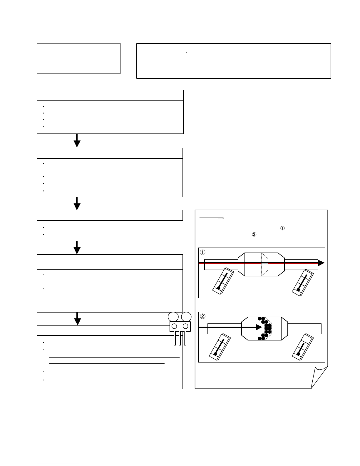
Attention
Trouble shooting 34
Forecast of Cause:
Check Point 2 : Check Outdoor Unit Operation
Check Point 1 : Check Indoor Unit
Check Point 3 : Check Site Condition
Check Point 5 : Check Refrigeration Cycle
Check Point 4 :
Check Indoor/ Outdoor Installation Condition
Pipe (In) Pipe (Out)
Pipe (In) Pipe (Out)
OKOK
OKOK
OKOK
OKOK
MPa MPa
No Cooling / No Heating
1. Indoor Unit error 2. Outdoor Unit error
3. Effect by Surrounding environment
4. Connection Pipe / Connection Wire failure 5. Refrigeration cycle failure
Does Indoor Unit FAN run on HIGH FAN?
Is Air Filter dirty?
Is Heat Exchanger clogged?
Check if Energy save function is operated.
Check if Outdoor Unit is operating
(If not, refer to Trouble shooting 32)
Check any objects that obstruct the air flow route.
Check clogged Heat Exchanger.
Is the Valve open?
Is capacity of Indoor Unit fitted to Room size?
Any windows open? Or direct sunlight ?
Check connection pipe
(specified pipe length & Pipe diameter?)
Check any loose or removed communication line.
>> If there is an abnormal condition, correct it by
referring to Installation Manual or Data & Technical
Manual.
Check if Strainer is clogged (Refer to the figure at right).
Measure Gas Pressure and if there is a leakage, correct it.
>> When recharging the refrigerant, make sure to perform
vacuuming, and recharge the specified amount.
Check EEV (PARTS INFORMATION 4)
Check Compressor (PARTS INFORMATION 1,2)
Strainer normally does not have temperature difference
between inlet and outlet as shown in , but if there is a
difference like shown in , there is a possibility of inside
clogged. In this case, replace Strainer.
07-33
Page 93
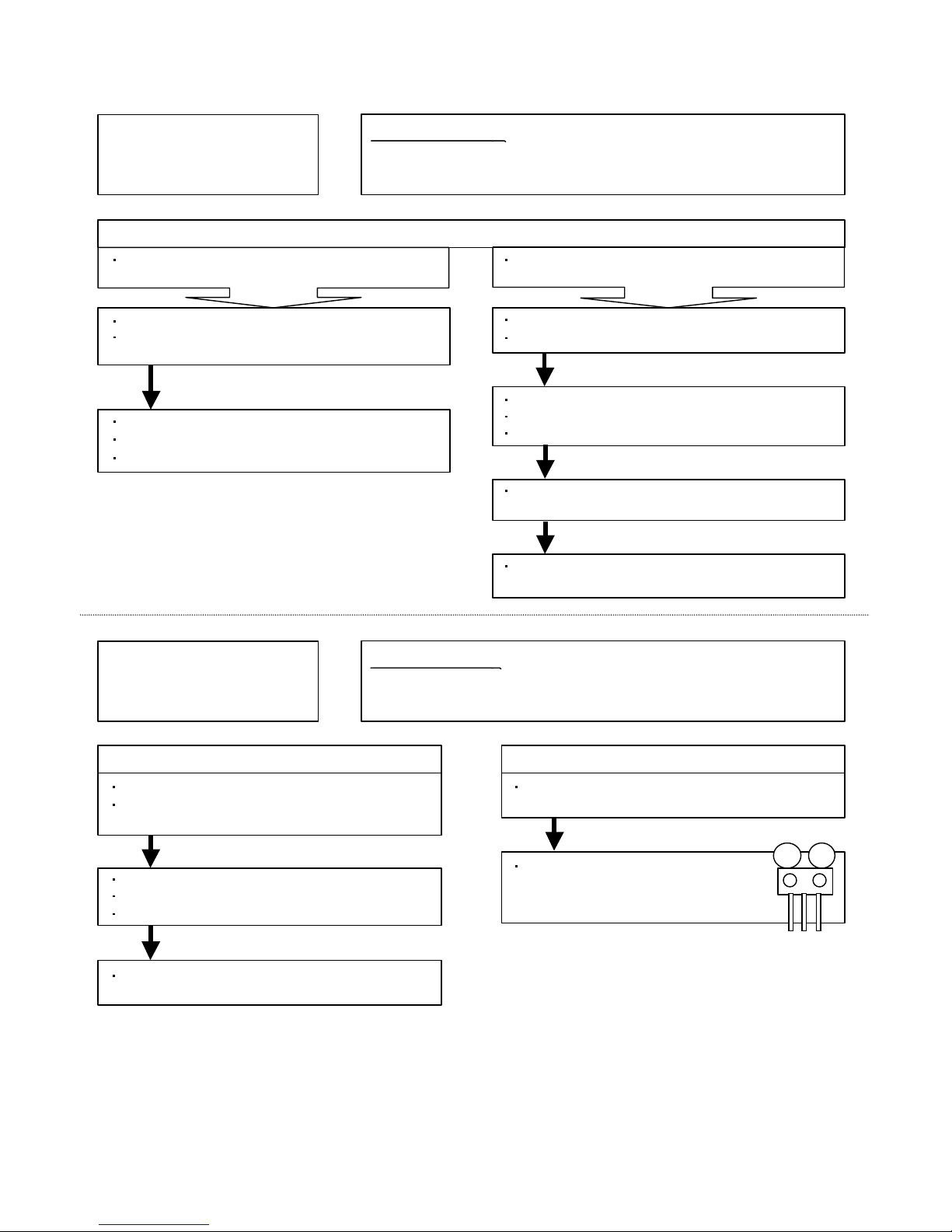
Trouble shooting 35
Forecast of Cause :
Trouble shooting 36
Forecast of Cause:
OK
OK
OK
OK
OKOK
OKOK
OKOK
MPa MPa
Abnormal Noise
1. Abnormal installation (Indoor/ Outdoor) 2. Fan failure(Indoor/ Outdoor)
3. Compressor failure (Outdoor)
Diagnosis method when Abnormal Noise is occurred
Abnormal noise is coming from Indoor Unit.
(Check and correct followings)
Abnormal noise is coming from Outdoor Unit.
(Check and correct followings)
Is Fan broken or deformed?
Is the screw of Fan loose?
Is there any object which obstruct the Fan rotation?
Is Main Unit installed in stable condition?
Is the installation of Air suction grille and
front panel normal?
Is Fan broken or deformed?
Is the screw of Fan loose?
Is there any object which obstruct the Fan rotation?
Is Main Unit installed in stable condition?
Is Fan Guard installed normally?
Check if vibration noise by loose bolt or contact noise
of piping is happening.
Is Compressor locked?
>> Check Compressor (PARTS INFORMATION 1,2)
Water Leaking
1. Erroneous installation 2. Drain hose failure
Diagnosis method when water is spitting out.
Is the filter clogged?
Check Gas Pressure and correct it
if there was a gas leak.
Diagnosis method when water leak occurs
Is Drain Hose connection loose?
Is there a trap in Drain Hose?
Is Drain Hose clogged?
Is Main Unit installed in stable condition?
Is Main Unit broken or deformed at the time of
transportation or maintenance?
Is Fan rotating?
07-34
Page 94
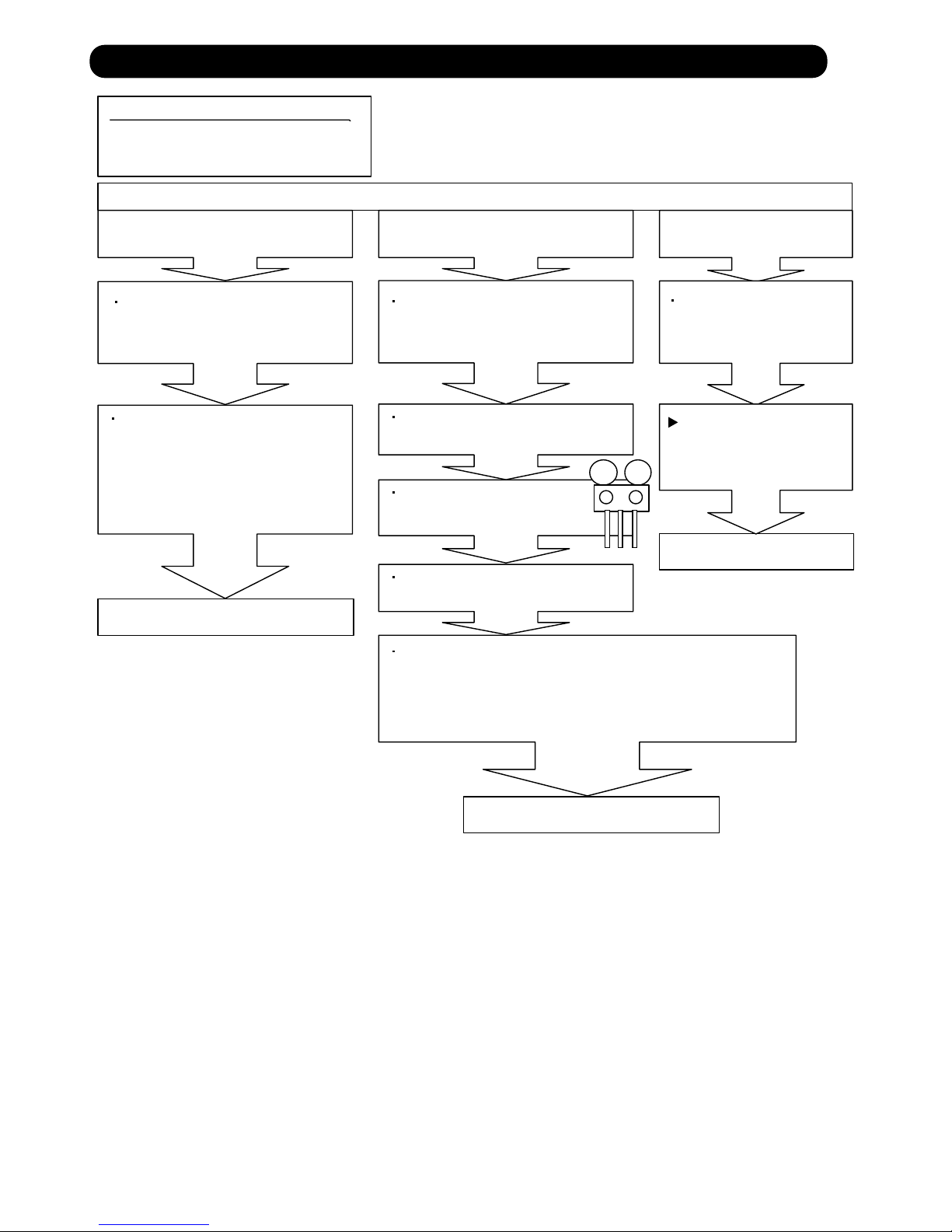
SERVICE PARTS INFORMATION 1
MPa MPa
Compressor
Diagnosis method of Compressor ( If Outdoor Unit LED displays Error, refer to Trouble shooting )
Does not start up
Is there open or loose connection
cable?
Check Filter PCB, Main PCB,
connection of Compressor,and winding
resistance. (Refer to the next page).
Check Filter PCB, Main PCB,
connection of Compressor,and winding
resistance. (Refer to the next page).
>> If there is no failure, the defect of
Compressor is considered (Locked
compressor due to clogged dirt or
less oil)
Replace Compressor
Replace Compressor
Replace Compressor
Stops soon after starting up
Is there open or loose connection
cable?
Is Gas Pipe Valve open?
(Low Pressure is too low)
Check if Refrigerant is leaking.
(Recharge Refrigerant)
Check if Strainer is clogged.
(PARTS INFORMATION 4)
>> If there is no failure, the defect of Compressor can be
considered. (Compression part broken or valve defective.)
Abnormal noise
Defective Compressor
can be considered.
(due to inside dirt clogging
or broken component)
Check if vibration noise by
loose bolt or contact noise
of piping is happening.
07-35
7-4 SERVICE PARTS INFORMATION
Page 95
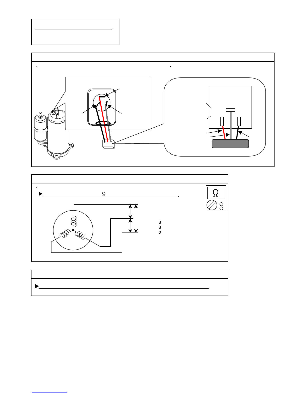
SERVICE PARTS INFORMATION 2
Check Point 1 : Check Connection
UU(RED)(RED)
V V (WHITE)(WHITE)WW
(BLACK)(BLACK)
Terminal cover opened
MAIN PCB
Check Point 2 : Check Winding Resistance
Check Point 3 : Replace Main PCB
U
V
W
W304
W305
W303
W8
W7
W9
RED
WHITE
BLACK
Compressor
Inverter Compressor
Check terminal connection of Compressor
(loose or incorrect wiring)
Check connection of Main PCB
(Loose or incorrect wiring)
Check winding resistance of each terminal
If the resistance value is 0 or infinite, replace Compressor.
If the symptom does not change with above Check 1, 2, replace Main PCB.
Resistance Value :
0.73 (For AR*A12L/ 14L/ 18L)
0.97 (For AR*A24L)
0.26 (For AR*A36L/ 45L)
at 20°C
07-36
AR*A12L-24L
AR*A36L/ 45L
Page 96
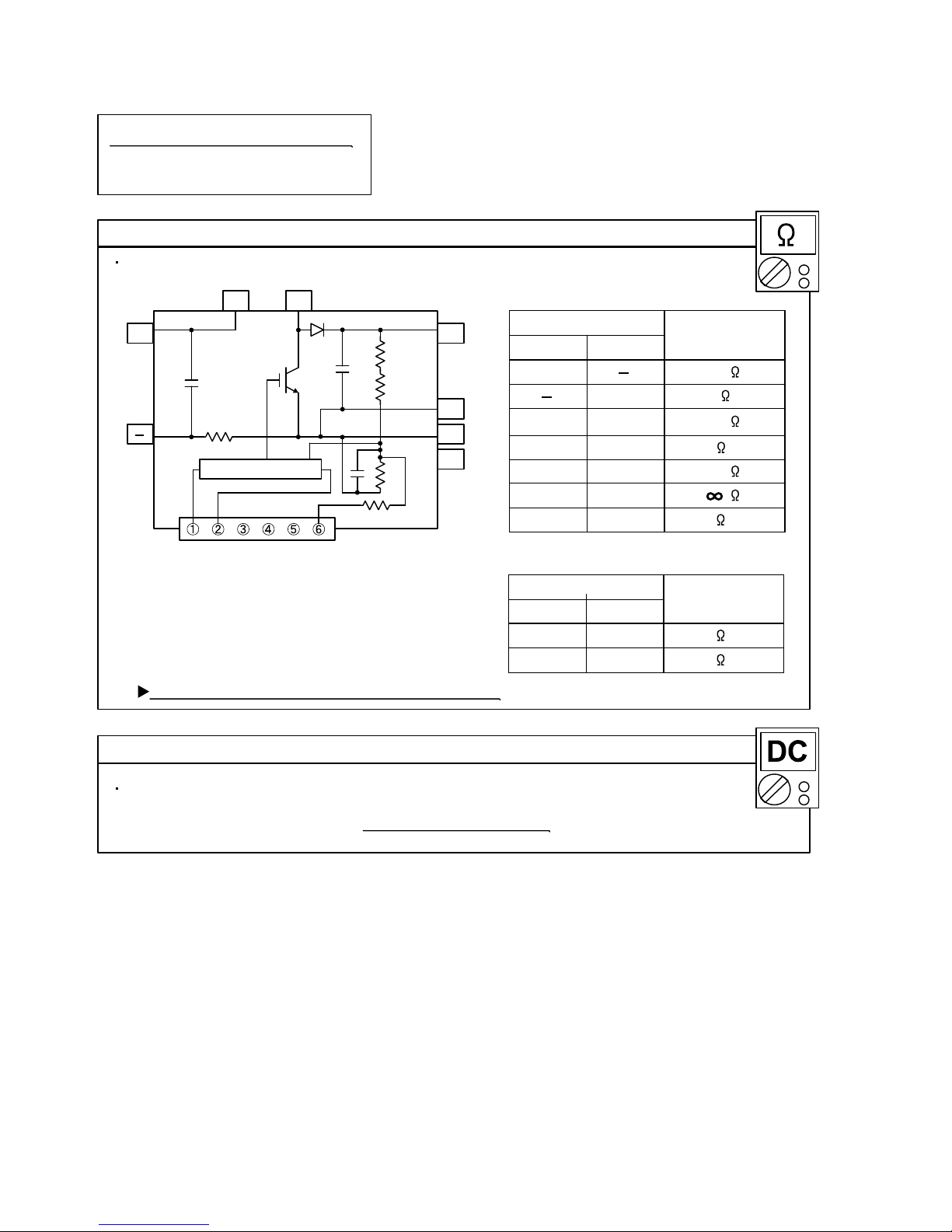
SERVICE PARTS INFORMATION 3
Check Point 1 : Check Open or Short-circuit and Diode (D1)
Check Point 2 : Check the Output DC voltage (between P and N1)
Terminal
Resistance value
L2L1
P
N2
N1
Power factor control
D1
(+)
( )
Io
L2
L1
L1,L2
P
P
Control Box
N1
N1
(+)
(+)
( )
( )
Tester(+) Tester(-)
Check the open or short-circuit
Check the Output DC voltage (between P and N1) of compressor stopping and operating.
Terminal
Resistance value
L2
P
P
N2
L2
L2
Tester(+) Tester(-)
Check the diode
If it is abnormal,replace ACTIVE FILTER MODULE
360k
0
360k
720k
5.4M (approx.)
5.3M (approx.)
5.8M (approx.)
5.4M (approx.)
Active Filter Module
Remove connector, check the open or short-circuit and the diode in the module
>> If the output voltage of compressor operating is less than the output voltage of compressor stopping,
Active Filter Module is detective. >> Replace Active Filter Module
07-37
( For AR*A36L/ 45L )
Page 97

SERVICE PARTS INFORMATION 4
Check Point 2 : Check Coil of EEV
Yellow - Brown
Orange - Red
Blue - Brown
White - Red
Read wire
46 4
Resistance value
Check Point 1 : Check Connections
Check Point 5 : Check Opening and Closing Operation of Valve
Check Point 3 : Check Voltage from Main PCB.
Check Point 4 : Check Noise at start up
Pipe (In)
Pipe (Out)
Hi TEMP.
Pipe (In)
Hi TEMP.
Normal TEMP.
CLOSE
Example : Hot Gas
OPEN
Example : Hot Gas
Pipe (Out)
Hi TEMP.
Pipe (In) Pipe (Out)
Pipe (In) Pipe (Out)
Check Point 6 : Check Strainer
DC
CN27
CN40
EXPANSION
VALVE COIL
EV
RED
BROWN
BLUE
ORANGE
YELLOW
WHITE
1
2
3
4
5
6
at 20°C
Outdoor unit Electronic Expansion Valve
( EEV )
Check connection of connector (CN27 or CN40)
( Loose connector or open cable )
Remove connector, check each winding
resistance of Coil.
If Resistance value is abnormal, replace EEV.
Remove Connector and check Voltage (DC12V)
If it does not appear, replace Main PCB.
Turn on Power and check operation noise.
If an abnormal noise does not show, replace Main PCB.
When Valve is closed,
it has a temp. difference between Inlet and Outlet.
If it is open,
it has no temp. difference between Inlet and Outlet.
Strainer normally does not have temperature difference between inlet and outlet as shown in ,
but if there is a difference as shown in , there is a possibility of inside clogged. In this case, replace Strainer.
07-38
CN40
(For AR*A12L-24L)
CN27
(For AR*A36L/ 45L)
Page 98

8 . APPENDING DATA
R410A
INVERTER
DUCT type
Page 99

08-01
MODEL : AR*A12LATN / AO*A12LACL
COOLING
HEATING
8-1. CAPACITY TABLE
8. APPENDING DATA
°CDB
°CWB
TC SHC PI TC SHC PI TC SHC PI TC SHC PI TC SHC PI TC SHC PI TC SHC PI
3.52 3.13 0.31 3.92 3.15 0.31 4.05 3.42 0.32 4.32 3.43 0.32 4.46 3.70 0.32 4.72 3.69 0.32 4.99 3.93 0.33
3.33 3.00 0.51 3.71 3.02 0.52 3.84 3.28 0.52 4.09 3.29 0.53 4.22 3.55 0.53 4.47 3.54 0.54 4.73 3.77 0.54
3.33 3.00 0.49 3.71 3.02 0.50 3.84 3.28 0.50 4.09 3.29 0.51 4.22 3.55 0.51 4.47 3.54 0.52 4.73 3.77 0.52
3.33 2.99 0.45 3.71 3.01 0.46 3.84 3.27 0.46 4.09 3.29 0.46 4.21 3.55 0.47 4.47 3.53 0.47 4.72 3.76 0.48
3.22 2.92 0.55 3.59 2.94 0.56 3.71 3.19 0.56 3.95 3.20 0.57 4.08 3.46 0.57 4.32 3.44 0.58 4.57 3.67 0.58
4.20 3.60 1.29 4.68 3.63 1.31 4.84 3.94 1.32 5.16 3.95 1.33 5.32 4.27 1.34 5.64 4.25 1.35 5.95 4.53 1.36
4.03 3.49 1.44 4.49 3.51 1.46 4.64 3.81 1.47 4.95 3.83 1.48 5.10 4.13 1.49 5.41 4.11 1.51 5.71 4.38 1.52
3.80 3.32 1.53 4.23 3.34 1.56 4.37 3.63 1.56 4.66 3.64 1.58 4.81 3.93 1.59 5.09 3.92 1.60 5.38 4.17 1.62
3.48 3.10 1.54 3.88 3.12 1.57 4.01 3.39 1.57 4.27 3.40 1.59 4.40 3.67 1.60 4.67 3.65 1.61 4.93 3.89 1.63
2.93 2.72 1.31 3.26 2.74 1.33 3.37 2.98 1.33 3.59 2.99 1.35 3.70 3.22 1.35 3.93 3.21 1.37 4.15 3.42 1.38
2.16 2.20 1.01 2.40 2.21 1.03 2.48 2.40 1.03 2.65 2.41 1.04 2.73 2.60 1.05 2.89 2.59 1.06 3.06 2.76 1.07
Outdoor temperature
Indoor temperature
182123
25
121516
183223
AFR
12.2
271929
21
°CDB
-10
0
5
10
15
20
25
30
35
40
46
°CDB
°CDB °CWB TC PI TC PI TC PI TC PI TC PI
-15 -16 3.41 1.87 3.32 1.91 3.24 1.95 3.16 1.99 3.08 2.03
-10 -11 4.16 1.87 4.06 1.91 3.96 1.95 3.86 1.99 3.76 2.03
-5 -7 4.76 2.15 4.65 2.19 4.53 2.24 4.42 2.28 4.26 2.30
0 -2 5.43 2.22 5.30 2.27 5.17 2.30 4.92 2.30 4.70 2.30
5 3 5.91 2.21 5.77 2.26 5.63 2.30 5.37 2.30 5.14 2.30
7 6 5.99 2.06 5.84 2.10 5.70 2.15 5.56 2.19 5.42 2.23
10 8 6.20 2.04 6.06 2.08 5.91 2.12 5.76 2.16 5.61 2.21
15 10 6.39 2.01 6.24 2.05 6.09 2.09 5.93 2.14 5.78 2.18
20 15 6.42 1.78 6.27 1.81 6.12 1.85 5.96 1.89 5.81 1.92
24 18 6.46 1.76 6.31 1.79 6.15 1.83 6.00 1.87 5.84 1.90
Outdoor temperature
Indoor temperature
1618202224
AFR
12.2
AFR : Air flow rate (m3/min)
TC : Total capacity (kW)
SHC : Sensible Heat capacity (kW)
PI : Power Input (kW)
AFR : Air flow rate (m3/min)
TC : Total capacity (kW)
PI : Power Input (kW)
Page 100

08-02
MODEL : AR*A14LATN / AO*A14LACL
COOLING
HEATING
°CDB
°CWB
TC SHC PI TC SHC PI TC SHC PI TC SHC PI TC SHC PI TC SHC PI TC SHC PI
4.06 3.64 0.36 4.52 3.67 0.36 4.68 3.98 0.36 4.99 4.00 0.37 5.14 4.32 0.37 5.45 4.30 0.37 5.76 4.58 0.38
3.97 3.58 0.42 4.42 3.60 0.43 4.57 3.91 0.43 4.87 3.92 0.43 5.03 4.24 0.44 5.33 4.22 0.44 5.63 4.50 0.44
3.84 3.49 0.53 4.28 3.51 0.54 4.43 3.81 0.54 4.72 3.82 0.54 4.87 4.13 0.55 5.16 4.11 0.55 5.45 4.38 0.56
3.70 3.38 0.63 4.12 3.40 0.64 4.26 3.70 0.64 4.54 3.71 0.65 4.68 4.01 0.65 4.96 3.99 0.66 5.24 4.25 0.67
3.75 3.42 0.55 4.18 3.44 0.56 4.32 3.74 0.56 4.60 3.75 0.57 4.75 4.05 0.57 5.03 4.03 0.58 5.32 4.30 0.58
4.78 4.17 1.20 5.32 4.19 1.22 5.51 4.56 1.22 5.87 4.57 1.24 6.05 4.94 1.24 6.41 4.92 1.26 6.78 5.24 1.27
4.56 4.01 1.35 5.08 4.03 1.37 5.25 4.38 1.38 5.60 4.40 1.39 5.77 4.75 1.40 6.12 4.73 1.41 6.47 5.04 1.43
4.33 3.84 1.50 4.82 3.86 1.52 4.98 4.20 1.53 5.31 4.21 1.55 5.48 4.55 1.55 5.81 4.53 1.57 6.13 4.82 1.59
4.27 3.79 1.78 4.75 3.81 1.81 4.91 4.15 1.82 5.24 4.16 1.84 5.40 4.49 1.85 5.72 4.47 1.87 6.05 4.77 1.88
3.12 2.97 1.27 3.47 2.99 1.29 3.59 3.25 1.29 3.83 3.26 1.31 3.95 3.52 1.31 4.18 3.50 1.33 4.42 3.73 1.34
2.22 2.34 0.96 2.47 2.35 0.98 2.56 2.56 0.98 2.73 2.56 0.99 2.81 2.77 1.00 2.98 2.76 1.01 3.15 2.94 1.02
Outdoor temperature
Indoor temperature
18212325272932
122123
AFR
13.7
151618
19
°CDB
-10
051015202530
35
40
46
AFR : Air flow rate (m3/min)
TC : Total capacity (kW)
SHC : Sensible Heat capacity (kW)
PI : Power Input (kW)
°CDB
°CDB °CWB TC PI TC PI TC PI TC PI TC PI
-15 -16 4.35 2.16 4.25 2.21 4.14 2.25 4.04 2.30 3.94 2.34
-10 -11 4.92 2.16 4.80 2.21 4.68 2.25 4.56 2.30 4.45 2.34
-5 -7 5.48 2.39 5.35 2.44 5.22 2.49 5.09 2.54 4.96 2.59
0 -2 6.29 2.56 6.14 2.61 5.99 2.67 5.84 2.72 5.69 2.77
5 3 7.04 2.74 6.88 2.80 6.71 2.85 6.46 2.87 6.17 2.87
7 6 6.83 2.35 6.66 2.40 6.50 2.45 6.34 2.49 6.18 2.54
10 8 7.08 2.40 6.91 2.45 6.74 2.50 6.57 2.55 6.40 2.60
15 10 6.71 2.06 6.55 2.10 6.39 2.14 6.23 2.19 6.07 2.23
20 15 6.28 1.64 6.13 1.67 5.98 1.71 5.83 1.74 5.68 1.78
24 18 6.47 1.64 6.32 1.68 6.16 1.71 6.01 1.75 5.85 1.78
13.7
Outdoor temperature
Indoor temperature
1618202224
AFR
AFR : Air flow rate (m3/min)
TC : Total capacity (kW)
PI : Power Input (kW)
 Loading...