

Page 1
Page 2

CONNECT2AIR™ WLAN AP-600RP-USB Page 1 / 62
CONNECT2AIR™ WLAN
AP-600RP-USB
Manual
Technical Support:
http://support.fujitsu-siemens.de/DriverCD/Accessories/_DriverSteuerung/GB/Accessories_WLAN.htm
Manual
Version 1.20 EN / June 22nd 2004 / Manual_AP-600RP-USB_V1-20_EN.pdf /
Referring to AccessPoint Firmware 7.3.3 / 7.4
© Copyright
The contents of this publication may not (in part or in full) be reproduced, stored, transcribed in an information retrieval
system, translated into any language or transmitted in any form or by any means, be it mechanical, magnetic, electronic,
optical, photocopying, manual or otherwise, without prior written permission.
Trademarks
All product, company and brand names are trademarks or registered trademarks of Fujitsu Siemens Computers. They
are used for identification purpose only. Specifications are subject to change without prior notice.
Page 3

CONNECT2AIR™ WLAN AP-600RP-USB Page 2 / 62
FCC Information
This device complies with Part 15 of the FCC Rules. Operation is subject to the following two conditions:
(1) This device may not cause harmful interference
(2) This device must accept any interference received; including interference that may cause undesired operation.
Federal Communications Commission (FCC) Statement
This equipment has been tested and found to comply with the limits for a Class B digital device, pursuant to
Part 15 of the FCC rules. These limits are designed to provide reasonable protection against harmful interference in a residential installation. This equipment generates, can radiate radio frequency energy and, if not
installed and used in accordance with the instructions, may cause harmful interference to radio communications. However, there is no guarantee that interference will not occur in a particular installation. If this equipment does cause harmful interference to radio or television reception, which can be determined by turning
the equipment off and on, the user is encouraged to try to correct the interference by one or more of the following measures:
• Adjust or relocate the receiving antenna.
• Increase the separation between the equipment and receiver.
• Connect the equipment to an outlet on a different circuit to that on which the receiver is connected.
• Consult the dealer or an experienced radio/TV technician for help.
CE Declaration of Conformity
This equipment complies with the requirements relating to electromagnetic compatibility, EN 55022/A1 Class
B, EN 300328-2 and EN 55024. This meets the essential protection requirements of the European Council
Directive 89/336/EEC on the approximation of the laws of the member states relation to electromagnetic
compatibility.
Please see http://www.fujitsu-siemens.com/wireless
WLAN AP-600RP-USB
for the declaration of conformity of the CONNECT2AIR
FCC RF Radiation Exposure Statement:
1. This transmitter must not be co-located or operate in conjunction with any other antenna or transmitter.
2. This equipment complies with FCC RF radiation exposure limits set out for an uncontrolled environment.
This equipment should be installed and operated with a minimum distance of 20 centimeters between
the radiator and your body.
LChannel / Usage Limitations
FRANCE: Only channels 10 to 11 (2457 MHz and 2462 MHz respectively) may be used on French terri-
tory. It is not permitted to operate the device on any other channel supported by the device.
Outdoor use is prohibited. See description in Section 8.4.7 “Wireless Settings”.
GREECE: For private indoor applications only.
Page 4

CONNECT2AIR™ WLAN AP-600RP-USB Page 3 / 62
CONTENT
1 INTRODUCTION ..........................................................................................................5
1.1 Five steps to success........................................................................................................ 5
2 FUNCTIONS AND FEATURES....................................................................................7
2.1 Included in delivery............................................................................................................7
3 WLAN: OVERVIEW .....................................................................................................8
3.1 IEEE Standards................................................................................................................. 8
3.2 Wireless Network Fundamentals....................................................................................... 8
3.2.1 Ad-hoc Mode (Peer-to-Peer Workgroup)................................................................... 8
3.2.2 Infrastructure Mode ................................................................................................... 9
3.3 Service Set Identification (SSID)....................................................................................... 9
4 HARDWARE INSTALLATION ...................................................................................10
4.1 Front Panel...................................................................................................................... 10
4.2 Rear Panel ......................................................................................................................10
4.3 Procedure for Hardware Installation................................................................................ 11
5 NETWORK SETTINGS ..............................................................................................12
5.1 Network Basics................................................................................................................ 12
5.2 Client Network Settings................................................................................................... 13
5.2.1 Network Settings ..................................................................................................... 13
5.2.2 Configuration of your Wireless Client ...................................................................... 13
5.2.3 Check the Connection ............................................................................................. 14
6 CONFIGURATION EXAMPLES.................................................................................15
6.1 AP-600RP-USB with ADSL Router ................................................................................. 16
6.2 AP-600RP-USB with ADSL Router (advanced) .............................................................. 17
6.3 AP-600RP-USB with ADSL Modem ................................................................................ 18
6.4 AP-600RP-USB with CABLE Modem.............................................................................. 19
6.5 Two AP-600RP-USB in repetition mode (WDS).............................................................. 20
7 SOFTWARE INSTALLATION....................................................................................21
7.1 Install AP Start-up Tool ................................................................................................... 21
7.2 User Manual.................................................................................................................... 21
8 ACCESSPOINT CONFIGURATION...........................................................................22
8.1 Start-up and Log In.......................................................................................................... 22
8.2 System Status ................................................................................................................. 23
8.3 Wizard ............................................................................................................................. 24
8.3.1 How to connect to your Internet Service Provider (ISP).......................................... 24
8.3.2 Wireless Settings..................................................................................................... 28
8.3.3 Wired Equivalent Privacy (WEP) Security............................................................... 29
8.4 Primary Setup.................................................................................................................. 30
8.4.1 LAN IP Settings ....................................................................................................... 30
8.4.2 DHCP Server Settings............................................................................................. 30
8.4.3 Client List................................................................................................................. 31
8.4.4 Address Reservation ............................................................................................... 32
8.4.5 DNS Settings........................................................................................................... 32
8.4.6 WAN Type Configuration / Connection to the Internet (ISP) ................................... 33
8.4.7 Wireless Settings..................................................................................................... 34
8.4.8 WLAN Security ........................................................................................................ 35
8.4.9 Security begins when Changing the Standard Password........................................ 36
8.4.10 Wired Equivalent Privacy (WEP) Settings............................................................... 37
8.4.11 Wi-Fi Protected Access™ (WPA)............................................................................ 38
8.4.12 IEEE 802.1x ............................................................................................................ 39
8.4.13 Radius Server.......................................................................................................... 40
8.4.14 Access Control List.................................................................................................. 41
8.4.15 DDNS (Dynamic DNS) ............................................................................................ 42
8.4.16 WDS ........................................................................................................................ 44
Page 5

CONNECT2AIR™ WLAN AP-600RP-USB Page 4 / 62
8.5 Advanced Settings .......................................................................................................... 45
8.5.1 Virtual Server........................................................................................................... 45
8.5.2 Firewall .................................................................................................................... 46
8.5.3 Time Zone ............................................................................................................... 52
8.5.4 DMZ......................................................................................................................... 52
8.6 Toolbox............................................................................................................................ 53
8.6.1 Administrator Toolbox ............................................................................................. 53
8.6.2 Firmware Upgrade................................................................................................... 53
9 ACCESS TO USB PRINTERS THROUGH WLAN ....................................................54
9.1 Configuration on Windows 2000/XP Platforms ............................................................... 54
Appendix A: Licensing Information............................................................................57
Appendix B: GNU GENERAL PUBLIC LICENSE ........................................................57
Page 6

CONNECT2AIR™ WLAN AP-600RP-USB Page 5 / 62
1 INTRODUCTION
Congratulations on your purchase of the outstanding Wireless Broadband Router AP600RP-USB. This product is specifically designed for small office and home office needs.
It provides a complete SOHO solution for Internet surfing and is easy to configure and operate even for non-technical users. Instructions for installing and configuring the AccessPoint (AP) can be found in this manual. Before you install and use this product, please
read this manual carefully to ensure that you take full advantage of its functionality.
1.1 Five steps to success
To enable smooth entry into the world of wireless LAN, you will be guided through the installation of the individual components by way of the ‘Five steps to success’. In so doing,
your specific level of technical expertise will be catered for. You decide which settings are
feasible for you.
Install
and configure
the
AccessPoint
Install
additional
features, such
as wireless
printing
START ¨
5
STEPS
TO
SUCCESS
Determine
your
network
knowledge
Define
your
network
topology
Prepare
your PCs
to connect
to the
AccessPoint
Page 7

CONNECT2AIR™ WLAN AP-600RP-USB Page 6 / 62
Determine your network knowledge
The success of the installation of your AccessPoint and wireless clients is largely independent of your technical skills. The more advanced and familiar you are with networking
terminology, the more intuitively you will act. Beginners will need more support in learning
about their new networking equipment. Some chapters are therefore supplemented with
additional information, designed especially for beginners:
Define your network topology
Decide which PC and devices will be connected to your network
• PC
• Laptop
• PDA
• Printer with USB port
• Network scanner
• Network printer
• …
Ä See Chapter 4 ‘Hardware Installation’ to help you to connect these devices properly.
Prepare your PCs and devices to connect to the AccessPoint
Before an AccessPoint can be configured, an initial connection must be established.
Ä See Chapter 5 ‘Network Settings’ to guide you through the settings.
Install and configure the AccessPoint
Your AccessPoint needs to be configured to work properly with each of your networking
components and your Internet connection.
Ä See Chapter 6 ‘Configuration Examples’.
Ä See Chapter 8 ‘AccessPoint Configuration’.
Install additional features – for example, a printer server
The AccessPoint is equipped with a printer port, which is wireless-accessible by any user
in the network. Every PC equipped with a Windows 2000 or Windows XP operating system
can access a USB printer connected to the AccessPoint without additional software.
Ä See Chapter 9 ‘ACCESS TO USB PRINTERS THROUGH WLAN’
Page 8

CONNECT2AIR™ WLAN AP-600RP-USB Page 7 / 62
2 FUNCTIONS AND FEATURES
• High-speed wireless LAN connection
54 Mbps data rate using the OFDM multicarrier modulation procedure
• Roaming
Seamless roaming within the IEEE 802.11b and 802.11g WLAN infrastructure
• IEEE 802.11b backward-compatible
Allows interoperability between multiple vendors based on the 802.11b standard
• Auto fallback
54, 48, 36, 24, 12, 9, 6 & 11, 5, 2, 1 Mbps data rate with auto fallback to the fastest
data rate available
• Broadband Internet access and NAT router
Connects multiple computers to the Internet through a broadband modem (cable or
DSL) or an Ethernet router
• Auto-sensing Ethernet switch
Equipped with a 4-port auto-sensing Ethernet switch with uplink capability
• VPN support
Supports multiple PPTP sessions to allow you to set up VPN servers and clients
• Printer sharing (wireless printing)
Integrated printer server to allow wireless printing for each networked computer Æ see
the list of compatible printers on the Internet.
• DHCP server support
All of the networked computers can obtain their TCP/IP (network communications protocol) settings automatically
• Web-based configuration
The AccessPoint can be configured through any networked computer’s web browser
(Netscape or Internet Explorer)
• Virtual server support
Enables you to run HTTP, FTP and other services through the virtual server to make
the services accessible to the users from the Internet.
• Firewall / packet filter support
The packet filter allows you to control access to a network by analyzing the incoming
and outgoing packets and letting them pass or blocking them based on the source IP
addresses.
2.1 Included in delivery
• CONNECT2AIR WLAN AP-600RP-USB AccessPoint
• Quick installation guide
• User Manual
• CD-ROM containing software and documentation
• Power adapter
• CAT-5 UTP Fast Ethernet cable
Page 9

CONNECT2AIR™ WLAN AP-600RP-USB Page 8 / 62
3 WLAN: OVERVIEW
Wireless LAN (WLAN) basically offers the same functionality and flexibility as a fixed network, allowing the configuration of both server-based networks and peer-to-peer connections.
While initial speeds were less than 1 Mbps per second, this figure has now risen to
54 Mbps. The first wireless networks were not governed by any standards, meaning that
only devices from the same vendor could communicate with each other. This situation improved considerably with the specification of the vendor-neutral IEEE standard.
The regulation authorities have accordingly legalized the following two frequency bands
compliant with the 802.11 standard within which WLAN devices are allowed to operate
(the appointed bandwidth in the two frequency bands differ from country to country, however):
2.4 GHz ISM (Industrial, Scientific and Medical)
5 GHz
WLAN shares its bandwidth with other clients or devices operating in the same frequency
(channel). Transmitting information from client 1 to client 2 offers 100% capacity, whereas
transmitting information from client 1 to 10 other clients will result in a decrease of bandwidth to 10% for each client (for example, 5.4 Mbps in 802.11g networks).
3.1 IEEE Standards
In order to guarantee a consistent and complete transmission of information from and to a
source/target WLAN device, the manner of transmitting data has to be defined. IEEE
therefore developed the IEEE WLAN standards with different modulation types:
802.11: First WLAN standard from 1997, license-free ISM band 2.4-GHz
bandwidth at max 3 Mbps
802.11a: Ratified standard for 54 Mbps in the 5-GHz band
802.11b: Most popular standard in the 2.4-GHz band at 11 Mbps
802.11g: 54 Mbps in the 2.4-GHz band but with better coverage than
802.11a products
11a
11b
11g
3.2 Wireless Network Fundamentals
3.2.1 Ad-hoc Mode (Peer-to-Peer Workgroup)
The Institute of Electrical and Electronics Engineers (IEEE) standard for wireless LANs
(WLANs), 802.11, offers two methods for configuring a wireless network — ad-hoc and infrastructure. In an ad-hoc network, computers
are brought together as needed; thus, there is
no structure, nor are there fixed points to the
network — each node can generally communicate with any other node. There is no AccessPoint involved in this configuration. It enables you to quickly set up a small wireless
workgroup and allows workgroup members to exchange data or share printers as supported by Microsoft networking in the various Windows operating systems. Some vendors
also refer to ad-hoc networking as peer-to-peer group networking.
Page 10
CONNECT2AIR™ WLAN AP-600RP-USB Page 9 / 62
In this configuration, network packets are sent and received directly by the intended
transmitting and receiving stations. As long as the stations are within range of one another,
this is the easiest and least expensive way to set up a wireless network.
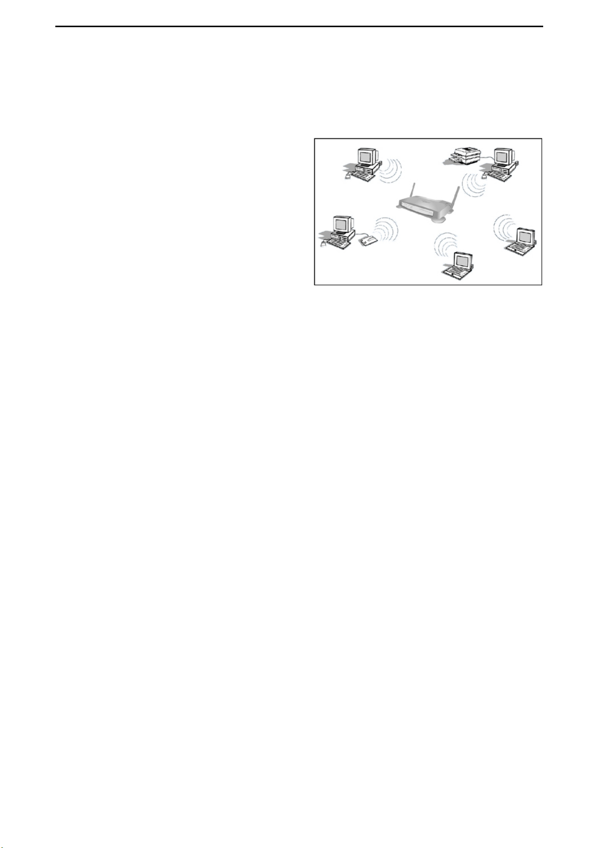
3.2.2 Infrastructure Mode
With a wireless AccessPoint, you can switch
the wireless LAN into infrastructure mode. It
provides wireless connectivity to multiple wireless network devices within a fixed range or
area of coverage, interacting with a wireless
node via an antenna.
In infrastructure mode, the wireless AccessPoint converts airwave data into wired
Ethernet data, acting as a bridge between the
wired LAN and wireless clients. Connecting
multiple AccessPoints via a wired Ethernet backbone can further extend the wireless network coverage. As a mobile computing device moves out of the range of one AccessPoint,
it moves into the range of another. As a result, wireless clients can freely roam from one
AccessPoint domain to another and still maintain seamless network connectivity.
3.3 Service Set Identification (SSID)
The Service Set Identification (SSID) is a max. 32 position alphanumeric character string
that identifies the wireless local area network. Some vendors refer to the SSID as the network name. For stations to communicate with each other, all stations must be configured
with the same SSID.
A wireless LAN consisting of nodes operating in an ad-hoc configuration without an AccessPoint is called a Basic Service Set (BSS). All nodes in a BSS must use the same Basic Service Set ID (BSSID).
In an infrastructure configuration with AccessPoints, multiple BSS can be configured to
form an Extended Service Set (ESS). In this configuration, the AccessPoints are configured with the same Extended Service Set ID (ESSID). Wireless clients configured with the
same ESSID can freely roam from one AccessPoint domain to another and still maintain
seamless connectivity with the network
Page 11
CONNECT2AIR™ WLAN AP-600RP-USB Page 10 / 62
4 HARDWARE INSTALLATION
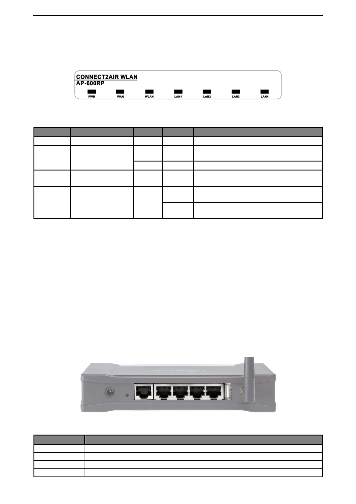
4.1 Front Panel
LED indicators
LED Function Color Status Description
PWR Power indication Green On The power is on.
WAN
WLAN
LAN 1 - 4
Link status
Wireless activity Green Flashing
Link status Green
Green On
Green Flashing The WAN port is sending or receiving data.
On
Flashing
RESET switch
To reset the system settings to factory defaults, please follow the steps:
1. Press the reset button and hold it for more than 10 seconds
2. Release the button
3. After every LED has flashed more than one time and only the LEDs related to a
set connection are lighting, the AccessPoint is active again.
4. It may take up to a minute to reconnect to the clients.
An active device is connected to the WAN
port.
Sending or receiving data via a wireless
link.
An active station is connected to the corresponding LAN port.
The corresponding LAN port is sending or
receiving data.
L All changes made to the AccessPoint are lost when the device is reset. Please refer
to Section 8.6.1 “Administrator Toolbox” for details of how to back up your settings.
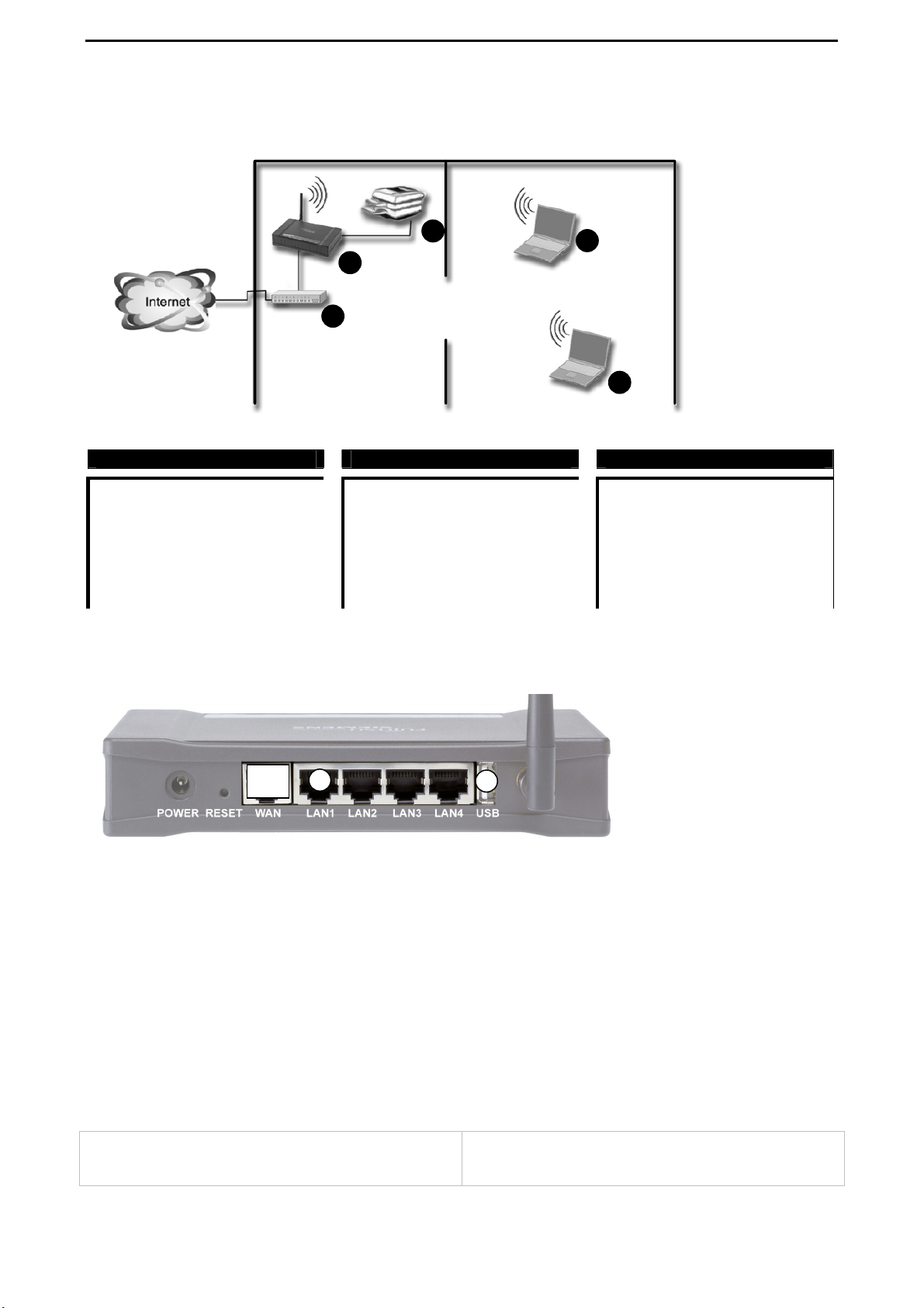
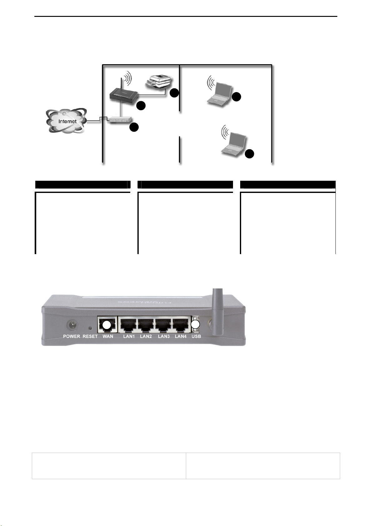
4.2 Rear Panel
POWER RESET WAN LAN1 LAN2 LAN3 LAN4 USB
Ports:
Port Description
POWER Power socket: DC 12V, 1.0A (minimum)
WAN The port for connecting your ADSL or cable modem
LAN 1-4 4 switch ports for your networked computers and/or other devices
USB Connector for any printer with a USB interface (Laser, Inkjet, Matrix)
Page 12
CONNECT2AIR™ WLAN AP-600RP-USB Page 11 / 62
4.3 Procedure for Hardware Installation
1. Decide where to place your AccessPoint
You can place your AccessPoint (AP) on a desk or another flat surface or mount it
on a wall. For optimum performance, place it in the center of your office (or your
home) in a location away from any potential source of interference, such as a metal
wall or microwave oven. This location must be close to a wall socket and a network
connection.
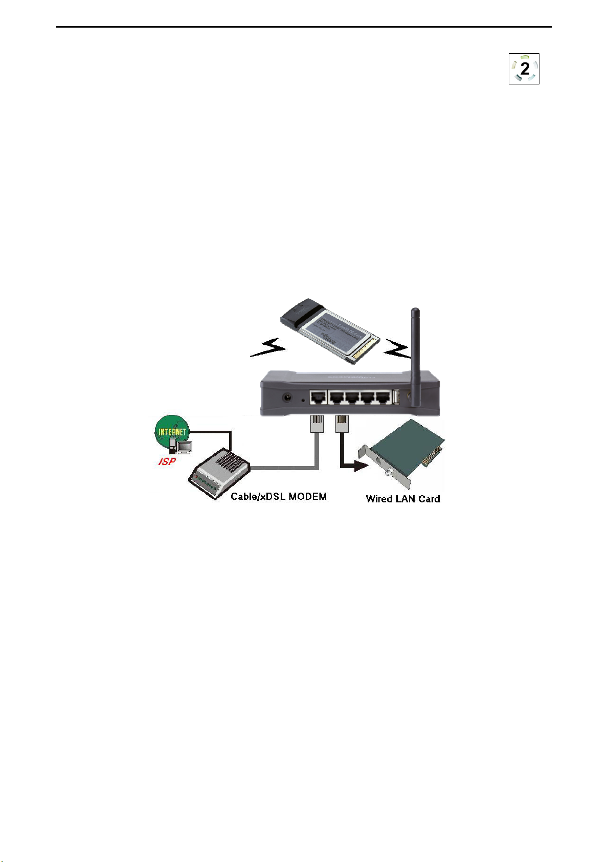
2. Set up a LAN connection
a) Wired LAN connection: Connect an Ethernet cable from your computer’s
Ethernet port to one of the AP’s LAN ports. You can use a standard Ethernet
cable or an Ethernet cross-cable: the AP can automatically detect either.
b) Wireless LAN connection: Move the AP to a proper position to ensure the best
transmission performance.
Figure 4-3 Setup of the AP’s LAN and WAN connections
3. Set up a WAN connection
Prepare an Ethernet cable for connecting the AP to your cable/xDSL modem or
Ethernet backbone. You can use a standard Ethernet cable or an Ethernet crosscable: the AP can automatically detect either. Figure 4-3 illustrates the WAN connection.
4. Connect the AccessPoint to your USB printer
Use the printer USB cable to connect your printer to the AP’s USB printer port.
5. Power on
Connect the power adapter to the power socket. Your AccessPoint then will automatically enter the self-test phase. During the self-test, the LAN LEDs will flash. Finally, the PWR LED will light permanently as the AccessPoint enters normal operation.
Page 13

CONNECT2AIR™ WLAN AP-600RP-USB Page 12 / 62
5 NETWORK SETTINGS
In order to use your AccessPoint and the printer server functionality correctly, it is necessary to ensure, that the network settings are configured correctly on your computers.
5.1 Network Basics
Every PC or device in a network is individually identified by a unique set of four
numbers, the so-called IP address. This IP address is one of the key elements in
opening up network communication between devices in order to exchange data,
such as the transfer of a file from one PC to another or simply receiving e-mails from your
ISP. More precisely, an IP address consists of a set of four numbers, each 3 digits long
and separated by a decimal point: for example: 192.168.100.200. These addresses can be
set manually or be received from a ‘DHCP server’, which manages a pool of IP addresses
in a network. Each IP address is accompanied by a default subnet mask. The combination
of these addresses (IP address and subnet mask) defines the segment in the network
where a specific device is located.
Your new AP-600RP-USB comes with a preset default IP address (192.168.1.254) and
“default subnet mask” (255.255.255.0), which can be changed by the user as required.
These default values are used as a reference in this manual. If the TCP/IP environment of
your computer has not yet been configured, refer to Appendix A to configure it.
Page 14
CONNECT2AIR™ WLAN AP-600RP-USB Page 13 / 62
5.2 Client Network Settings
5.2.1 Network Settings
Regardless of whether you are using a wireless or wired device to connect to your AccessPoint, all the following steps must be followed for your network adapter:
1. From the Windows Start button on your PC, choose Settings and select the Control
Panel item.
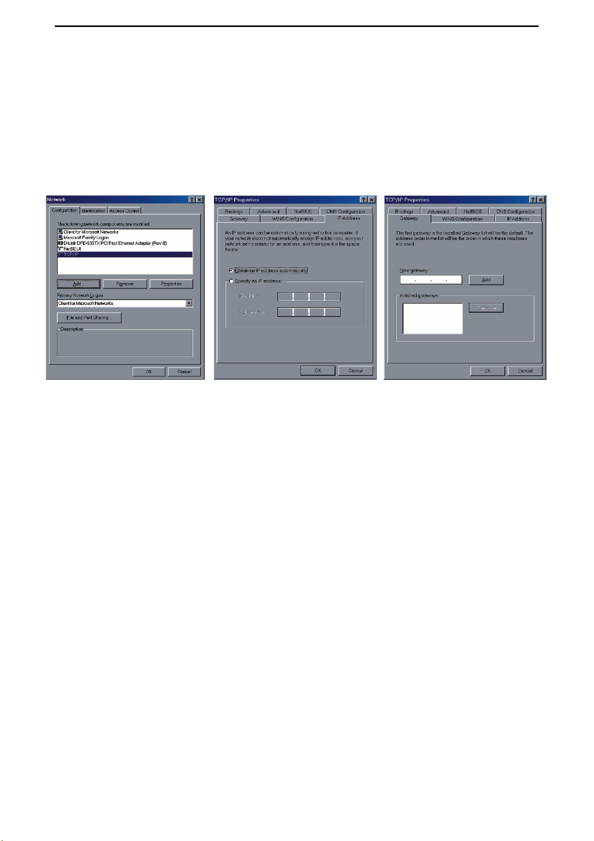
Step 2 Step 3 Step 4
2. Double click the Network Connections icon (network card that is connected to the
AccessPoint).
3. Select the TCP/IP adapter associated with your network card on the Configuration
tab in the Network window.
4. Click the Properties button. Click the IP Address tab. Select Obtain an IP Address
automatically.
5. Click the Gateway tab. Clear and remove all of the gateway settings. Click the OK
button.
All the necessary settings, including the IP address and subnet mask will be provided
L
from the AP.
5.2.2 Configuration of your Wireless Client
To open a wireless connection to your AccessPoint, it is necessary to configure the wireless client device in your PC:
• Network mode: Infrastructure
• Network name (SSID): CONNECT2AIR or ANY
• Security: disabled
• Channel (frequency): automatic
• IP address: obtain automatically
These parameters can be entered in the user interface of your network card. Please refer
to the documentation delivered with your device.
L Recent client configuration utilities detect the wireless settings automatically.
Page 15
CONNECT2AIR™ WLAN AP-600RP-USB Page 14 / 62
5.2.3 Check the Connection
Your wireless client has to be configured properly to connect to the AP.
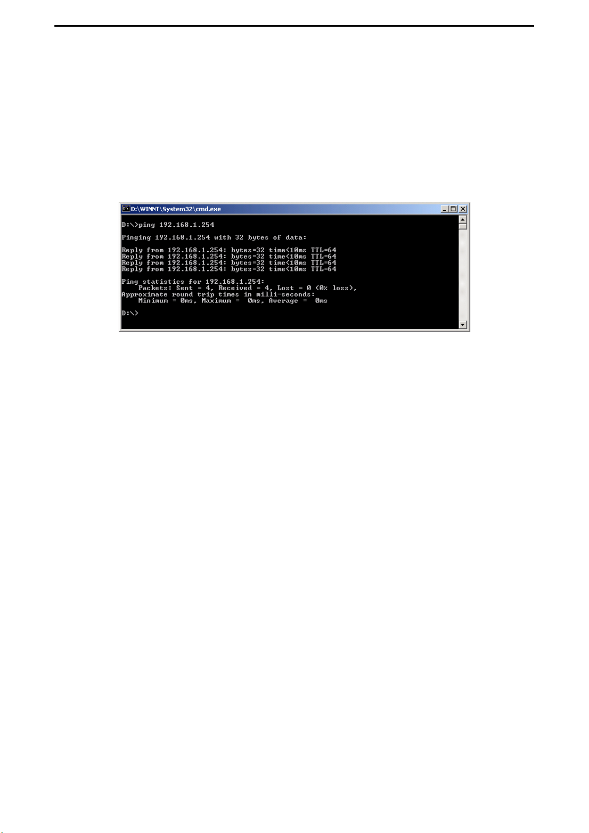
When the TCP/IP communication protocol has been installed, you can use the ping command to check if your computer has successfully connected to the AccessPoint. The following example shows the ping procedure for Windows platforms.
Open a DOS command box by clicking “Start” and selecting “Run”. Type in “command” for
Windows 98 / ME or “cmd” for all other Windows-based operating systems.
First execute the “ping” command, which will check whether or not the device with the entered IP address is ready to communicate: ping 192.168.1.254
If a communication link between your computer and the AccessPoint has been established
successfully, the output will show four ‘replies’ from your AP.
L If your request timed out, no connection was established between your client and the
AP. If you ‘pinged’ the correct IP address, there must be something wrong with your
installation.
Please check the following items in sequence:
1. Is the Ethernet cable correctly connected between the AP and your computer?
Tip: The AP’s LAN LED and the link LED on the network card in your computer
must be lighting.
2. Is the TCP/IP environment of your computer properly configured?
Tip: If the AP’s IP address is 192.168.1.254 (default), the IP address of your
computer must be 192.168.1.X (X ≠ 254) and default gateway must be
192.168.1.254.
3. If your AP has been used before, reset it to its default settings.
Page 16

CONNECT2AIR™ WLAN AP-600RP-USB Page 15 / 62
6 CONFIGURATION EXAMPLES
The AP-600RP-USB offers a wide range of configuration possibilities due to the extended
feature set. This chapter helps you to manage more complex configuration schemes and
helps you in configuring your AccessPoint as well as other devices in the network, like
ADSL Routers.
Inexperienced users and professionals will the information they require according to their
knowledge. You will find an overview on how the configuration should look. Compare it
with your settings and adopt it.
Chapter 8 “AccessPoint configuration” will help you with setting up the device as described
in the configuration examples.
Page 17
CONNECT2AIR™ WLAN AP-600RP-USB Page 16 / 62
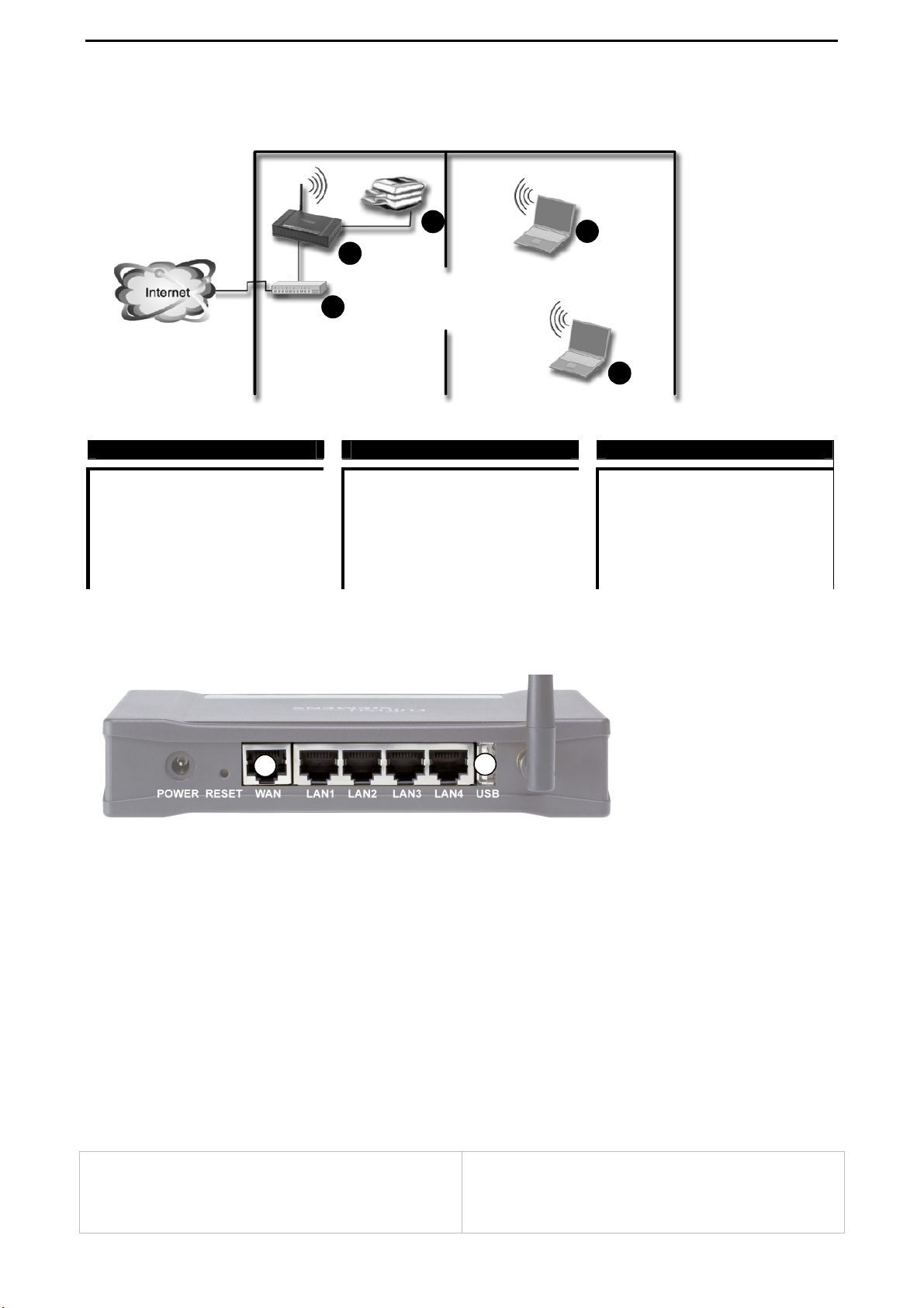
6.1 AP-600RP-USB with ADSL Router
4
2
1
( 1 ) ADSL Router
WAN: PPPoE over ADSL
LAN: static IP: 192.168.1.1
DHCP on: 192.168.1.10 - 90
GW: 192.168.1.1
DNS: auto
( 2 ) AP-600RP-USB
WAN: no ISP
LAN: static IP: 192.168.1.254
DHCP disabled
Routing: off (cable from Router
connected to the LAN
interface)
SSID: CONNECT2AIR
Connecting the devices to the AP-600RP-USB:
3
3
( 3 ) Notebook
TCP/IP: get IP and DNS address
automatically
SSID: CONNECT2AIR
Data Rate: auto
Connect the ADSL Router to one of the LAN port, not to the WAN port. Additional networking devices like network printers, servers or scanners can be plugged to one of the free
LAN ports and will be integrated in the IP segment of 192.168.1.X.
Installation Note
The AccessPoint as well as the ADSL Router have routing capabilities. Therefore it is
suggested to operate the AccessPoint only as a Wireless Bridge. Connecting the ADSL
Router to one of the LAN ports will put the AccessPoint into the bridging mode. The
network management will therefore also be handled by the ADSL Router (DHCP, etc.).
ADSL Router:
- DHCP Server
- managing the PPPoE session
AP-600RP-USB:
- handling the wireless LAN (WLAN) access
Page 18
CONNECT2AIR™ WLAN AP-600RP-USB Page 17 / 62
6.2 AP-600RP-USB with ADSL Router (advanced)
4
2
1
( 1 ) ADSL Router
WAN: PPPoE over ADSL
LAN: static IP: 192.168.1.1
DHCP on: 192.168.1.10 - 90
GW: 192.168.1.1
DNS: auto
( 2 ) AP-600RP-USB
WAN: dynamic IP address
LAN: static IP: 192.168.4.254
DHCP on: 192.168.4.10 - 90
GW: 192.168.4.254
DNS: auto
Routing: on (cable from Router
connected to the WAN
interface)
SSID: CONNECT2AIR
Connecting the devices to the AP-600RP-USB:
3
3
( 3 ) Notebook
TCP/IP: get IP and DNS addresses
automatically
SSID: CONNECT2AIR
Data
rate: auto
Installation Note
Both the AccessPoint as well as the ADSL Router have routing capabilities. This case describes using both devices in the router mode in order to have the full feature set of the
AccessPoint active, like the Firewall, NAT or the packet forwarding service.
Important: The IP segment of the ADSL Router has to be different from the one of the
AccessPoint, otherwise the APs Router will not work properly. Due to production process,
the third IP segment of the AccessPoint must be different to 192.168.2.X, as the default
WAN setting for “static IP address” is set to 192.168.2.1 .
ADSL Router:
- DHCP Server (on or off)
- managing the PPPoE session
AP-600RP-USB:
- DHCP Server
- handling the wireless LAN (WLAN) access
- NAT Routing, Firewall are active
Page 19
CONNECT2AIR™ WLAN AP-600RP-USB Page 18 / 62
6.3 AP-600RP-USB with ADSL Modem
4
2
1
( 1 ) ADSL Modem ( 2 ) AP-600RP-USB ( 3 ) Notebook
No configuration necessary
WAN: PPP over Ethernet
LAN: static IP: 192.168.1.254
DHCP on: 192.168.1.10 - 90
GW: 192.168.1.254
DNS: auto
SSID: CONNECT2AIR
3
3
TCP/IP: get IP and DNS
addresses
automatically
SSID: CONNECT2AIR
Data Rate: auto
Connecting the devices to the AP-600RP-USB:
Connect the ADSL Modem to the WAN port, otherwise the PPPoE session cannot be established and therefore the Internet service cannot be opened. Additional networking devices like network printers, servers or scanners can be plugged into one of the free LAN
ports and will be integrated in the IP segment of 192.168.1.X.
Installation Note
Most broadband Internet connections are nowadays established over an ADSL Modem.
This case describes using an ADSL modem for connection to the WLAN AccessPoint. The
configuration is quite easy and allows you to share one single Internet connection with
several other Clients.
Important: Please check thoroughly if you have a Modem or a Router in view of the
completely different configurations.
ADSL Modem:
- establishing Internet connection
AP-600RP-USB:
- handling PPPoE session
- DHCP Server
- handling the wireless LAN (WLAN) access
- NAT Routing, Firewall are active
Page 20

CONNECT2AIR™ WLAN AP-600RP-USB Page 19 / 62
6.4 AP-600RP-USB with CABLE Modem
4
3
2
1
3
( 1 ) Cable Modem ( 2 ) AP-600RP-USB ( 3 ) Notebook
The Cable Modem does not have
to be configured.
WAN: dynamic IP address
LAN: static IP: 192.168.1.254
DHCP on: 192.168.1.10 - 90
GW: 192.168.1.254
DNS: auto
Routing: on (cable from Modem
connected to the WAN
interface)
SSID: CONNECT2AIR
TCP/IP: get IP and DNS
addresses
automatically
SSID: CONNECT2AIR
Data Rate: auto
Connecting the devices to the AP-600RP-USB:
Connect the CABLE Modem to the WAN port. Additional networking devices like network
printers, servers or scanners can be plugged into one of the free LAN ports and will be
integrated in the IP segment of 192.168.1.X.
Installation Note
Beside ADSL, most broadband Internet connections are nowadays established over CABLE Modem (TV cabling). This case describes using a CABLE modem for connection to
the WLAN AccessPoint. The configuration is quite easy and allows you to share one single
Internet connection with several other Clients.
CABLE Modem:
- establishing Internet connection
AP-600RP-USB:
- DHCP Server
- handling the wireless LAN (WLAN) access
- NAT Routing, Firewall are active
Page 21

CONNECT2AIR™ WLAN AP-600RP-USB Page 20 / 62
X
6.5 Two AP-600RP-USB in repetition mode (WDS)
4
3
5
4
4
2
1
( 2 ) AP-600RP-USB Floor 1 ( 3 ) AP-600RP-USB Floor 2 ( 4 ) Notebook
WAN: PPP over Ethernet
LAN: static IP: 192.168.1.254
subnet Mask: 255.255.255.0
DHCP on: 192.168.1.10 - 90
GW: 192.168.1.254
DNS: auto
SSID: CONNECT2AIR
Channel: 11 (same as AP 2)
WDS: MAC addr. of AP-600RP-USB 2
listed in the table
The ADSL Modem (1) does not have to be configured.
WAN: no ISP
LAN: static IP: 192.168.1.253
subnet Mask: 255.255.255.0
GW: 192.168.1.254
DHCP disabled
SSID: CONNECT2AIR
Channel: 11 (same as AP 1)
WDS: MAC addr. of AP-600RP-USB 1
listed in the table
TCP/IP: get IP and DNS
addresses
automatically
SSID: CONNECT2AIR
Data Rate: auto
Connecting the devices to the AP-600RP-USB:
AP-600RP-USB Floor 1
AP-600RP-USB Floor 2
Connect the ADSL Modem to the WAN port of the AP1, otherwise the PPPoE session
cannot be established and therefore the Internet service cannot be opened. Additional
networking devices like network printers, servers or scanners can be plugged into one of
the free LAN ports of the AP1 or AP2 and will be integrated in the IP segment of
192.168.1.X.
Installation Note
In order to have more range, up to 6 AccessPoints can be linked together. This case describes the configuration of linking two APs together where AP1 is the managing one,
which initiates the PPPoE session and acts as DHCP server. The SSID and the radio
channel must be equal for all APs linked, otherwise no connection can be established. Furthermore, every AP has to know its counterpart, therefore a MAC address table is provided
to enter the appropriate AccessPoint.
Page 22

CONNECT2AIR™ WLAN AP-600RP-USB Page 21 / 62
7 SOFTWARE INSTALLATION
The software provided with the installation WLAN CD contains all drivers, documentation
and software for WLAN products available from Fujitsu Siemens Computers.
Exit any software applications you have running on your computer and insert the installation CD-ROM into the CD-ROM drive. The following window is shown automatically.
Select 'AccessPoint' from the menu shown on the left side, and then 'AP-600RP-USB'.
You can then choose from the various options appearing on the right side of the panel.
7.1 Install AP Start-up Tool
The AccessPoint start-up tool will automatically launch the browser with the correct IP set,
regardless of any changes to your network settings.
Click the button to start the installation and follow the dialog boxes offered by the wizard.
7.2 User Manual
A program called “Acrobat Reader” is required to read the copy of the User Manual on the
CR-ROM. If it is not yet installed on your computer, click the “Install Acrobat Reader” button to proceed with the installation.
Page 23

CONNECT2AIR™ WLAN AP-600RP-USB Page 22 / 62
8 ACCESSPOINT CONFIGURATION
This product is provided with a Web-based configuration interface that can be accessed
via your Web browser, such as Internet Explorer, Netscape Communicator or any other
HTML-compatible browsers. This interface can be launched with any Microsoft Windows,
Macintosh or UNIX-based platforms.
8.1 Start-up and Log In
To enter the AccessPoint configuration either:
• Launch the “AccessPoint Start-up Tool” on your desktop or from
“Start/Programs/CONNECT2AIR/WLAN/AP-600RP-USB/ConfigStarter”.
• Activate your browser directly and type in the IP address of your AP in the Address field
(for Internet Explorer) or in the Location field (for Netscape) and press ENTER. Default
value is: 192.168.1.254
Once the connection is established, the AP’s password protection window will pop up. To
log in, enter the system password (the factory setting is “connect”) in the System Password field and press the “Enter” button. You will then be prompted to choose your preferred language: English, German, French, Italian and Spanish are available.
Page 24

CONNECT2AIR™ WLAN AP-600RP-USB Page 23 / 62
8.2 System Status
This section shows the AP’s working status:
• AccessPoint properties
The wireless network name is displayed.
• Wide Area Network (WAN)
The status of the WAN port will be displayed as well as the connection type.
• Local Area Network (LAN)
The IP address, DHCP server and the firewall status are displayed
• Wireless Settings (WLAN)
If enhanced security has been set, it will be displayed. The Access Control displays the
status of the WLAN access possibilities – for example, WEP, 802.1x or Radius.
• Printer Status
Possible values for the printer status include “Ready”, “Not ready”, and “Printing…”.
Page 25

CONNECT2AIR™ WLAN AP-600RP-USB Page 24 / 62
8.3 Wizard
The Wizard section will guide you through the main settings for your AccessPoint. You will
be prompted to select your ISP (Internet Service Provider) and to check your security settings.
8.3.1 How to connect to your Internet Service Provider (ISP)
It is vitally important that you read this chapter carefully in order to choose the right
settings to connect to your ISP (Internet Service Provider). As described in the
hardware installation, you must connect your modem to the WAN port (DSL, cable
modem) of your AP.
Select your ISP and click on "Next". You will then be prompted to fill in the appropriate information.
Static IP Address
WAN IP address, subnet mask, standard gateway and your gateway: Enter the settings
provided by your ISP.
Page 26

CONNECT2AIR™ WLAN AP-600RP-USB Page 25 / 62
Dynamic IP Address
All settings are provided by the ISP or are automatically accepted by the AccessPoint.
The Host Name can be optionally entered. Some ISPs require this item.
Dynamic IP addressing can be useful if the AccessPoint is to be integrated into an existing networking environment, but the WLAN clients are nonetheless to address a different address range.
PPP over Ethernet (e.g. ADSL connection)
This is the default setting for connecting the AP to a DSL modem.
PPPoE Username and Password: Enter the account and password that your ISP has
assigned to you. For security, this field appears blank. If you don't want to change the
password, leave it empty.
MAC address: If a specific MAC address is to be mirrored to the ISP only for the dura-
tion of the PPPoE session, enter this address manually.
IP address (optional): Enter the fixed IP address provided by the ISP here (if applica-
ble), if you plan to run a public server, for example. Otherwise, leave the box empty.
PPPoE Connection Type: Select “auto-connection” if the Internet connection shall
only be opened when requested by the user. After the PPPoE Timeout with no activity
has been reached, the session will be closed automatically. Select “Dial-up on demand” if you want to control the connection manually. In addition, a button Connect/Disconnect will be added on the bottom of the page.
Page 27

CONNECT2AIR™ WLAN AP-600RP-USB Page 26 / 62
L Use „auto-connection“ if you do not have a connection with flatrate (no capacity
download restriction). Please check thoroughly if your AP is disconnecting. This
can be done via the status page or check your ISPs accounting information. Selecting “Dial-up on demand” and starting the connection will not be terminated
upon the user's request.
Disconnect PPPOE Session: If selected, the connection is automatically set up and
disconnected after the specified connection time has elapsed. If the option is disabled,
even though the connection is established automatically, it will not be disconnected –
i.e., the connection is permanent.
PPPoE Timeout: The time of inactivity before disconnecting your PPPoE session.
Minimum value is 60 seconds. No input is possible if "Disconnect PPPOE Session" is
disabled.
PPPoE Status: Indicates the status of the DSL connection – for example, "Initializing"
(of the connection) or "Connected" once a connection with the Internet has been set
up.
PPTP
PPTP Username and Password: The account and password that your ISP assigned
to you. This field is displayed empty for security reasons. If you don't want to change
the password, leave the field empty.
IP Address and Subnet Mask: The private IP address and subnet mask that your ISP
assigned to you.
PPTP Server: The IP address of the PPTP server.
Phone number (optional): Enter the telephone number here if the provider specifies
so.
Page 28

CONNECT2AIR™ WLAN AP-600RP-USB Page 27 / 62
• L2TP
Use the information provided by the provider for making your L2TP settings.
• Without an ISP
If you wish to use the device purely as an AccessPoint (i.e., without connection to a
provider), select this option. The routing functionality is disabled as a consequence.
The AccessPoint operates as a gateway between the LAN and WLAN – i.e., to make
the wireless clients (e.g., network printers) accessible.
Page 29

CONNECT2AIR™ WLAN AP-600RP-USB Page 28 / 62
8.3.2 Wireless Settings
• Country / Region:
Select the country in which the AccessPoint is to be used. The selection determines
which radio channels can be used to transmit and receive signals as regulated by the
corresponding authorities.
• Wireless network ID (SSID):
Network ID is used for identifying the wireless LAN (WLAN). Client stations can roam
freely between different AccessPoints that have the same network ID. The factory setting is “CONNECT2AIR”.
• Band (modulation type):
The AP can be operated in either of two different modulation types or a compatibility
mode: high rate – 54 Mbps, low rate – 11 Mbps, or a mix of both in the 2.4-GHz ISM
band. The latter is a mixed network in which high rate and low rate devices can share
the same wireless frequency band for mutual communication. This mode offers the advantage of full backward compatibility with 802.11b devices. 54-Mbps-only cards communicate with each other at the high data rate.
Note: Because dramatic reductions in throughput will result from simply attaching
L
legacy 802.11b clients to the 802.11g network, a new, powerful and flexible technology is provided additionally to ensure protection and increased performance. Please
refer to Turbo mode below for details.
• Radio Channel:
The radio channel number. The permissible channels range from channel 1 to 13 (default is 11), depending on the regulatory domain. For restrictions, please refer to the
first page of this manual.
• Turbo mode / NitroTM mode:
A technology that delivers throughput enhancement in both mixed and 802.11g-only
networks, while improving stability at the same time. Activation of the turbo mode is
particularly recommended in the case of mixed networks.
• Hide SSID:
Suppresses display of the SSID so that only wireless clients that already know the
SSID can use the AccessPoint. Note, however, that this offers only little protection for
your network as software is available on the Internet to detect the information.
Page 30

CONNECT2AIR™ WLAN AP-600RP-USB Page 29 / 62
8.3.3 Wired Equivalent Privacy (WEP) Security
Use this security standard to obtain at least the minimum in security in your WLAN. To use
WEP in the AccessPoint, all clients must have standardized security settings. The WEP
keys must therefore be adapted directly after configuration of the AccessPoint. Please refer to the detailed information given in Section 0.
WEP keys 1, 2, 3 & 4:
When you enable the 64- or 128-bit WEP algorithm, please select one WEP key to be
used. If you are using a 128-bit key (recommended), you have to enter a 26-digit hexadecimal key (0, 1, 2…8, 9, A, B…F) in the appropriate field:
Example 128 bit: FEDCBA01234567890123456789 26 digits
Example 64 bit: FEDCBA0123 10 digits
Passphase generator: Since hexadecimal characters are difficult to memorize, this device offers a conversion utility from a simple word into the hexadecimal code. Click the key
you want to update, enter your passphrase and press “Generate Keys”. The key is then
updated. Proceed likewise with the other three keys if necessary. Manual entry of the keys
in the client is recommended.
Once the WEP security settings are complete, you also have to copy them to the client as
otherwise further configuration of the AccessPoint, at least via wireless clients, is no longer
possible (AP with WEP, wireless client without WEP ► no further communication).
L
Note: Even if different suppliers or even devices within the same brand support the
passphrase generator, it cannot be taken as a given that keys generated from different devices will be the same. Therefore always keep your keys saved and compare them against each other in the AccessPoint and in the clients.
You now have reached the end of the Wizard.
All settings are now stored in the device.
Page 31

CONNECT2AIR™ WLAN AP-600RP-USB Page 30 / 62
8.4 Primary Setup
These core options are essential to enable the AP to work properly. The available settings
and the interface depend on the WAN type. Choose the correct WAN type before you
start.
8.4.1 LAN IP Settings
Do not change the IP address of the AccessPoint unless you have adapted the settings on
the DHCP server. Otherwise all clients retrieving their IP address from the AP will loose
their connection and will not be reconnected. Changing the IP address will cause a disconnect from the AP after pressing Save.
• LAN IP Address Type:
Two selections are provided. If you plan to use any external DHCP server, first enter
the settings on the DHCP server page and disable the default DHCP sever, then return
to this page and select Dynamic. Otherwise set the LAN address to Static and make
sure the IP address is in the range of the DHCP server in which the default DHCP
server is usually enabled.
• LAN IP Address:
The local IP address of this device. The computers in your network must use this LAN
IP address as their default gateway.
• Subnet Mask:
Defines the size of the subnet mask range. 255.255.255.0 (default) permits an address
range from 192.168.1.1 to 192.168.1.254, for example. This means that the first three
segments must always be identical and that the last segment in the range from 1–254
is freely selectable.
• Gateway:
Optional. For connections to a different network (e.g., Internet over DSL), the gateway
defines the first point of entry for the AccessPoint. No entry is required – entering a
gateway address would define an alternative path.
8.4.2 DHCP Server Settings
The settings for a TCP/IP environment include host IP, subnet mask, gateway, and DNS
configurations. It is not easy to manually configure all the computers and devices in your
network. Fortunately, the DHCP server provides a rather simple approach to handling all of
these settings. This product supports the function of the DHCP server. If you enable the
DHCP server and configure your computers as “automatic IP allocation” mode, the clients
will automatically load the proper TCP/IP settings from the AP when the computer is pow-
Page 32

CONNECT2AIR™ WLAN AP-600RP-USB Page 31 / 62
ered up. The DHCP server settings include the following items and can be “Disabled” or
“Enabled”.
• IP Pool Starting / Ending Address:
Whenever requested to allocate IP addresses, the DHCP server will automatically allocate an unused IP address from the IP address pool to the requesting computer. You
must specify the start and end address of the IP address pool.
• Netmask:
Defines the size of the subnet mask range. 255.255.255.0 (default) permits an address
range from 192.168.1.1 to 192.168.1.254, for example. This means that the first three
segments must always be identical and that the last segment in the range from 1–254
is freely selectable. Consequently, 254 clients can communicate with each other within
the address range 192.168.1.X.
• Gateway:
The gateway represents the connection and exchange node (AccessPoint) through
which IP networks are connected together. For connections to a different network (e.g.,
Internet over DSL), the gateway defines the first point of entry for the AccessPoint. No
entry is required as the gateway is automatically assigned to all clients via the DHCP
server – entering an IP address would define an alternative path.
• Lease Time (minutes)
The default time value for clients to retain the assigned IP address. DHCP automatically renews IP addresses without client notification. Default is 300 minutes.
L Note: Do not forget to adapt the DHCP server to the IP settings of the AccessPoint.
8.4.3 Client List
The table entries represent all devices that have obtained an IP address from the AccessPoint's DHCP server. In addition, clients with fixed addressing are also entered in the list
Æ see the next section.
Page 33

CONNECT2AIR™ WLAN AP-600RP-USB Page 32 / 62
8.4.4 Address Reservation
In spite of the use of a DHCP server, fixed allocation of IP addresses is possible within the
network – by address reservation. With this function you can assign a particular IP address
to a MAC address. Each time the client is connected via LAN or WLAN, the address is assigned to him.
L Note: Entries can only be added or deleted once the DHCP server has been dis-
abled.
8.4.5 DNS Settings
As an alternative to the DNS address copied from the provider, a manual DNS address
can be provided to the clients through the DHCP server. The AP-600RP does not have a
DNS server and therefore cannot provide its own IP address as a DNS entry. The DNS
entry of the provider is always transferred to the clients as a result. This can be overriden
by means of a manual entry to the DNS settings. If no provider is defined, and there are no
manual DNS entries, the AP transfers a fixed DNS entry: 168.95.1.1.
L Note: Entries can only be added or deleted once the DHCP server has been dis-
abled.
Page 34

CONNECT2AIR™ WLAN AP-600RP-USB Page 33 / 62
8.4.6 WAN Type Configuration / Connection to the Internet (ISP)
WAN Type: Select the appropriate WAN connection type for your ISP. You can choose
between different types by clicking on "Change".
The different WAN types are described in Section 8.3.1.
You can clone a MAC address by copying a specific address to the field and pressing
Save. Alternatively, you can click on Clone MAC Address to have the MAC address of
the interface and PC used to configure the AccessPoint entered in the AP also. If your
Internet provider saves your MAC address, this function can be useful to exclude the possibility of multiple usage of the connection.
Page 35

CONNECT2AIR™ WLAN AP-600RP-USB Page 34 / 62
8.4.7 Wireless Settings
• Country / Region:
Select the country in which the AccessPoint is to be used. The selection determines
which radio channels can be used to transmit and receive signals as regulated by the
corresponding authorities.
• Wireless network ID (SSID):
Network ID is used for identifying the wireless LAN (WLAN). Client stations can roam
freely between different AccessPoints that have the same network ID. The factory setting is “CONNECT2AIR”.
• Band (modulation type):
The AP can be operated in either of two different modulation types or a compatibility
mode: high rate – 54 Mbps, low rate – 11 Mbps, or a mix of both in the 2.4-GHz ISM
band. The latter is a mixed network in which high rate and low rate devices can share
the same wireless frequency band for mutual communication. This mode offers the advantage of full backward compatibility with 802.11b devices. 54-Mbps-only cards communicate with each other at the high data rate.
L Note: Because dramatic reductions in throughput will result from simply attaching
legacy 802.11b clients to the 802.11g network, a new, powerful and flexible technology is provided additionally to ensure protection and increased performance. Please
refer to Turbo mode below for details.
• Radio Channel:
The radio channel number. The permissible channels range from channel 1 to 13 (default is 11), depending on the regulatory domain. For restrictions, please refer to the
first page of this manual.
• Turbo mode / NitroTM mode:
A technology that delivers throughput enhancement in both mixed and 802.11g-only
networks, while improving stability at the same time. Activation of the turbo mode is
particularly recommended in the case of mixed networks.
• Hide SSID:
Suppresses display of the SSID so that only wireless clients that already know the
SSID can use the AccessPoint. Note, however, that this offers only little protection for
your network as software is available on the Internet to detect the information.
Page 36

CONNECT2AIR™ WLAN AP-600RP-USB Page 35 / 62
8.4.8 WLAN Security
To protect your intellectual property, secure your wireless connection! This AccessPoint is equipped with a sophisticated security algorithm to protect against intruders
entering your system or listening to what you are transferring over your network.
Security is divided in two parts: Authentication and Encryption.
Authentication:
• Who is my partner to whom I am sending data / Who am I?
• How can I guarantee that I am myself?
• How can I guarantee that I am still myself – while sending data?
Authentication is needed in order to guarantee your identity. The authority that identifies
the client is a so-called RADIUS server. On the client side, an 802.1x protocol is responsible for handling the authentication process.
Encryption:
• How can I ensure that no third party is reading my data?
• How can I ensure that my data has not been changed during the transmission process?
Encryption guarantees safe communication between two parties. All data is encrypted at
the source and decrypted at the destination. Two types of encryption are available within
this device: WEP (Wired Equivalent Privacy) and dynamic WEP with periodically changing
keys.
WPA (Wi-Fi Protected Access) is a mix of both authentication and encryption in a single
application. It provides a legacy WEP (dynamic WEP) and standard authentication enhancement (802.1x). As it does not need a RADIUS server, it fits optimally into the home
and SoHo environment as it provides a high level of security.
L All devices in your WLAN must be configured identically so that they can
communicate with each other. First configure the AP and take note of your settings. Once the settings have been applied, the connection to the clients will be
lost (e.g. AP with WEP / clients no WEP). Proceed by updating all of your clients, which can then reconnect to the AP.
What type of security to check:
To help you achieve the right level of security, the table below indicates the different levels
of security that can be applied to your AP and devices:
AUTHENTICATIONENCRYPTION
SEC level WEP dyn WEP WPA PSK WPA EAP 802.1X RADIUS Usage
ad-hoc session
Home
SoHo
SoHo
Home / SoHo
SoHo / Enterprise
NONE
LOW
HIGH
::::::
;
;
:
::
:::
:::::
:::
;
::
;
:::
;;
;;
;;
auto
;
Page 37

CONNECT2AIR™ WLAN AP-600RP-USB Page 36 / 62
Wireless Security Settings:
The AP-6000RP-USB offers five methods for achieving a WLAN with enhanced security.
As described in the table above, there are dependencies between authentication and encryption. Entries are therefore needed at different levels of the AP's graphical user interface (GUI).
8.4.9 Security begins when Changing the Standard Password
The security of your WLAN begins when changing the standard password and ends with
the encryption of the data. The following three steps at least are recommended:
1. Change the password of your AccessPoint Section 8.6.1
2. Enable WPA for securing the wireless link Section 8.4.11
3. Suppress display of the SSID (hide SSID) Section 8.4.7
Page 38

CONNECT2AIR™ WLAN AP-600RP-USB Page 37 / 62
A
8.4.10 Wired Equivalent Privacy (WEP) Settings
Use this security standard to obtain at least the minimum in security in your WLAN. To use
WEP in the AccessPoint, all clients must have standardized security settings. The WEP
keys must therefore be adapted directly after configuration of the AccessPoint.
WEP keys 1, 2, 3 & 4:
When you enable the 64- or 128-bit WEP algorithm, please select one WEP key to be
used. If you are using a 128-bit key (recommended), you have to enter a 26-digit hexadecimal key (0, 1, 2…8, 9, A, B…F) in the appropriate field:
Example 128 bit: FEDCBA01234567890123456789 26 digits
Example 64 bit: FEDCBA0123 10 digits
Passphase generator: Since hexadecimal characters are difficult to memorize, this device offers a conversion utility from a simple word into the hexadecimal code. Click the key
you want to update, enter your passphrase and press “Generate Keys”. The key is then
updated. Proceed likewise with the other three keys if necessary. Manual entry of the keys
in the client is recommended.
Once the WEP security settings are complete, you also have to copy them to the client as
otherwise further configuration of the AccessPoint, at least via wireless clients, is no longer
possible (AP with WEP, wireless client without WEP ► no further communication).
L
Note: Even if different suppliers or even devices within
the same brand support the passphrase generator, it
cannot be taken as a given that keys generated from different devices will be the same. You should therefore always use just one passphrase generator for creating keys
in the wireless network. Add the keys manually. Always
carefully compare the entries in the AccessPoint and in
the clients.
PPLICATION
Secure your WLAN by applying
WEP to every AccessPoint and
client in your WLAN. Instead of
WEP, use the more secure
WPA if clients with a supplicant
(software) are available.
Always use the highest available security level and key
length (128 bits).
Page 39

CONNECT2AIR™ WLAN AP-600RP-USB Page 38 / 62
A
8.4.11 Wi-Fi Protected Access™ (WPA)
WPA: Besides VPN (Virtual Private Network), currently one of the highest levels of security
a wireless network can achieve. Wi-Fi Protected Access™ is a multistage security specification and has been introduced as an interim solution for most known security weaknesses in relation to plain WEP. TKIP (Temporal Key Integrity Protocol), the successor to
WEP, includes enhancements that eliminate the known vulnerabilities of WEP, and ensures that the basic key is periodically switched so that not enough information can be collected to decrypt data.
WPA for SOHO applications
SOHO users can use WPA with user-defined keys. To do so, select the Pre-Shared Key
Mode and enter a password. Then save the configuration to activate WPA.
L A shared key can only be regarded as being secure provided no third party knows
of it.
WPA – Enterprise Mode
Companies employing RADIUS-based authentication can use
WPA with 802.1x (WPA-EAP/enterprise mode). An EAP (extensible authentication protocol) is used with a new encryption
method called Temporal Key Integrity Protocol (TKIP).
L A WLAN client with WPA capabilities is needed for
working with the AccessPoint (so-called supplicant).
Vendors nowadays offer upgrades for their cards or
have newer generations ready that apply to the new
WLAN security standard, Wi-Fi Protected Access™,
and its future successor, IEEE 802.11i.
PPLICATION
WPA (Pre-Shared Key):
Only the shared secret can be
set as an option. Authentication
and encryption are handled
automatically.
WPA (Enterprise Mode) with
dynamic WEP (TKIP):
If WEP is not activated in Primary Settings / WLAN Security
/ WEP, WPA will automatically
set the encryption type to dynamic WEP (TKIP) -> recommended. 802.1x will be
launched automatically, which
allows a rekeying based on
bandwidth or time. Otherwise
WEP (TKIP) will be used as
defined in the WEP (TKIP)
settings.
Page 40

CONNECT2AIR™ WLAN AP-600RP-USB Page 39 / 62
A
8.4.12 IEEE 802.1x
IEEE 802.1x is a standard for network access control (port-based), which was introduced
especially for distributing encryption keys in a wireless network. The AccessPoint supports
802.1x for keeping out unauthorized users and for verifying the credentials of users with
RADIUS so that authorized users can access the network and services.
To use 802.1x, you will need at least one common Extensible
Authentication Protocol (EAP) method on your authentication
server, APs (authenticator) and stations (supplicant). 802.1x is
also used to perform generation and distribution of encryption
keys from AP to the station as part of or after the authentication
process. A further factor here is dynamic WEP, which is based
on legacy RC4 WEP encryption and is available in this AccessPoint under the setting for enabling 802.1x security in association with disabled Wired Equivalent Privacy (WEP) settings. There are two options for the key length, i.e. 40 and 104
bits. The longer the key length, the greater security it will offer.
PPLICATION
802.1x and Radius Server:
An 802.1x client needs to be
combined with a Radius server.
The server acts as an authentication authority, the AccessPoint as an authenticator and
the client as supplicant.
Windows XP already comes
with integrated 802.1x capabilities and can therefore be used
directly in combination with a
Radius server.
Page 41

CONNECT2AIR™ WLAN AP-600RP-USB Page 40 / 62
A
8.4.13 Radius Server
RADIUS (Remote Authentication Dial-In User Service) plays a central role in the network
in providing the capabilities of authenticating, authorizing, accounting, auditing and alarming, etc. and allows an organization to maintain user profiles in a central database that all
remote servers can share. Since RADIUS is relatively complex to explain, we will focus
here on how it acts as an 802.1x authentication server (EAP-aware RADIUS) and assists
in enhancing security.
RADIUS performs the authentication function required to check the credentials of users
and intermediate AccessPoints and indicates whether the users are authorized to access
the AccessPoints. Enabling RADIUS is therefore the first step toward building up an
802.1x-capable environment. Even more, it is also a must-do to accommodate the recently
introduced Wi-Fi Protected Access™ (WPA-EAP) to wireless networks.
Setting up RADIUS information in your AccessPoint is quite simple; just input the relevant
IP address for RADIUS and the port number, which is usually set to 1812, as well as the
secret key, which is identified with the given key in RADIUS. Æ Press Add to apply the settings.
When you finish adding RADIUS information, return to the
Wireless Security Settings page, where you will be allowed to
continue configuring 802.1x as the picture shows. You can
choose here to have either 802.1x with static WEP or with dynamic WEP and WPA-EAP to ensure even greater security in
your wireless network.
PPLICATION
802.1x and Radius Server:
An 802.1x client needs to be
combined with a Radius server.
The server acts as an authentication authority, the AccessPoint as an authenticator and
the client as supplicant.
Windows XP already comes
with integrated 802.1x capabilities and can therefore be used
directly in combination with a
Radius server
Page 42

CONNECT2AIR™ WLAN AP-600RP-USB Page 41 / 62
8.4.14 Access Control List
The MAC Address Control allows you to assign different access rights for different users
and to assign a specific IP address to a certain MAC address. A distinction is made as to
whether the AccessPoint always allows access to each client, or if it excludes all clients.
This means that specific clients also have to be assigned high-level rights. Administrators
therefore always have access to the AccessPoint regardless of the general access mode.
Tick the “enable” box to activate MAC address control. All of the settings on this page will
only take effect when “Enable” is ticked. Note that all settings made to the AP are stored if
you disable MAC address control.
The following settings are recommended:
1. General access mode: reject.
2. Access list: Enter the administrator PC in the access list with the property "Allow
access".
3. Extend the access list for the acceptable users (allow access) and hackers or "freeloaders" (reject access).
General access mode
“ALLOW” clients to access your AP:
All devices in the MAC address control table will have access to the network if “Accept” is
ticked as well. The AccessPoint is accessible to everyone.
“DENY” clients access to your AP:
No devices have access to the AccessPoint and its resources.
Page 43

CONNECT2AIR™ WLAN AP-600RP-USB Page 42 / 62
User-specific access list:
Rights (always allow access / deny access) are assigned to the clients in the table independently of the general access mode.
If a client is always to have access to the whole network (e.g., an administrator), his or her
MAC address is added with the property Accept access policy.
In contrast, any user that is known to access the WLAN without authorization can be excluded from the network by means of Reject access.
L Never reject a MAC address in the general Reject access mode if it communicates
with the only device listed (e.g., the PC that configures the AccessPoint). Doing so
would exclude the device as no connection would be allowed to the AP.
8.4.15 DDNS (Dynamic DNS)
The DDNS service enables you to access a local server in the LAN/WLAN from the Internet. The service connects a static host name (e.g., MyWebcam.dyndns.org) with the dynamic IP address of the device to be addressed (e.g., a web camera or a web server). The
service is useful if you are connected, for example, by a DSL or cable modem to your provider. It changes at will the IP address assigned to the router. Consequently, the web
camera, for example, is only available via the Internet through the public IP address as
long as the IP address is not changed. DDNS combines the advantage of easier access to
local network resources via a web address with the automatic update of the IP address.
Example configuration of a publicly accessible WEBcam:
This configuration covers three areas in the AccessPoint:
1: Registration of a host name under www.dyndns.org, for example
2: Parametrization of the DDNS client in the AccessPoint
Page 44

CONNECT2AIR™ WLAN AP-600RP-USB Page 43 / 62
Enter the user name and password you configured for your DDNS provider.
If you use a wildcard, all host names will be diverted to the main host. For example,
First.mycam.dyndns.org or Second.mycam.dyndns.org would be diverted to the host
named mycam.dyndns.org.
3: Release of the route in the virtual server
In the WEBcam example (preconfigured to the IP address 192.168.1.10) the vendor notes
that the ports 80 and 7070 are required for communication and control (motor zoom).
These must be added to the virtual server using Add. The WEBcam can only be accessed
over the Internet in this way.
As a result, all IP packets with port 80 or 7070 at the WAN interface of the AccessPoint are
diverted to the internal IP address 192.168.1.10 (WEBcam).
L The WEBcam can always dynamically obtain an IP address instead of a fixed
one. However, since there is a direct link between a port and a specific IP
address in the virtual router, the service only functions while the WEBcam
has no other address. In this case, it is recommendable to assign the MAC
address of the WEBcam permanently to an IP address Æ see DHCP / Address Reservation.
Page 45

CONNECT2AIR™ WLAN AP-600RP-USB Page 44 / 62
A
8.4.16 WDS
Extend the range of your network without having to use cables to link the AccessPoints by
using the Wireless Distribution System (WDS): Normally, AccessPoints are linked to each
other via cables. With WDS, you can link the AccessPoints wirelessly.
Upon calling the WDS settings, a list of available AccessPoints is displayed. In the left
field, mark the relevant WDS-supporting AP with which the WDS connection is to be set
up. Then click on Save. Repeat the procedure for all items. The WDS link cannot be set up
until all items have been configured.
Use rescan to display all the AccessPoints that are running on the same channel and select the one(s) you want to get a connection.
Alternatively, enter the MAC address of another AP you wirelessly want to connect to into
the appropriate field at the end of the page and click Add. It will then be listed in the table.
Assign a name to it in order to have it properly identified and press Save. Repeat the procedure for all items. The WDS link cannot be set up until all items have been configured.
Up to eight WDS links can be used at the same time.
L Tips for configuring a WDS:
• AccessPoint 1 is in reach of AccessPoint 2
• Identical radio channel and modulation mode (802.11g /11b or mixed) applied to both
APs
• Enter MAC address of the peer AccessPoint in the table (do it for both APs)
• Every AccessPoint in a chain of WDS has to be configured with a unique IP address.
This can be done by manually configuring every AP or by switching to get the IP address dynamically (Primary Settings / LAN IP).
Æ Example: Static IP address:
AP1: 192.168.1.254
AP2: 192.168.1.253
Subnet mask: 255.255.255.0
SSID: CONNECT2AIR
Channel: 6
PPLICATION
More Range:
Your third floor is not in reach of
your AP-600RP-USB: Place
another AP in reach of the first
one and configure both as
being linked by WDS. You will
then automatically be able to
have access to any of the resources that AP1 is related to.
Page 46

CONNECT2AIR™ WLAN AP-600RP-USB Page 45 / 62
8.5 Advanced Settings
8.5.1 Virtual Server
The router built into the AP-600RP-USB allows specific ports – and therefore their associated services – to be enabled for communication for particular clients. In this way, local
servers or other resources can be released for communication. This is done by selecting a
client in the virtual server (specific IP address) and defining the port to open. All requests
sent to this port are forwarded through the IP address to the specified computer.
The virtual server acts as a selective "guard" on the WAN side (Internet) in that it grants
access to the local network (WLAN/LAN) to specified services, and denies all other services this right. Each service (used synonymously in this context for a port and the associated application) must be assigned to a particular IP address in the local network so that
packet forwarding is possible.
Service Function TCP UDP
AUTH Authentication Service 113 113
BOOTPC Bootstrap Protocol Client 67
DNS Domain Name Server 53
FTP File Transfer Protocol 21
HTTP Hyper Text Transfer Protocol 80
NETBIOS-SSN Netbios Session Service 139
NNTP Network News Transfer Protocol 119
NPP Network Printing Protocol 92
NTP Network Time Protokol 123
POP3 Post Office Protocol V3 110
PPTP Point to Point Tunneling Protocol (VPN) 1723
SMTP Simple Mail Transfer Protocol 25
SNMP Simple Network Management Protocol 161
Telnet Terminal Emulation Protocol 23
TFTP Trivial File Transfer Protocol 69
For example, if you have an FTP server (port 21) at 192.168.1.13, a web server (port
8080) at 192.168.1.12, and a VPN server at 192.168.1.14 (port 173), you need to make
the following entries in the virtual server mapping table:
Another example configuration with a WEBcam can be found in Section 8.4.15 DDNS
(Dynamic DNS).
Application:
Use a comma (,) or dash (-) if more than one port is to be added – for example: 20, 21 or
20–25 or 20, 25–30, 50. Up to 50 entries can be added to the table. Port ranges are also
listed individually in the table.
Page 47

CONNECT2AIR™ WLAN AP-600RP-USB Page 46 / 62
8.5.2 Firewall
The firewall is a set of programs located at the gateway, which limits the exposure of a
computer or a group of computers to users in the WAN network or Internet. Based on the
default policies and the specified rules, network administrators can easily manage the traffic from any network access. The default policies allow you to accept or block all traffic.
You can also define rules: these determine what to do with specific types of traffic where
rules override the default policies.
The firewall offers extended protection against DoS (denial of service) attacks. Clients
connected to the Internet are exposed to attacks of this nature. Here, a third party attempts
to render the client or the host network inaccessible by bombarding the client with countless IP packets until the client's resources become exhausted. With DDOS (distributed
denial of service), the attacks come in groups, which increases the extent of the damage.
The router is also equipped with NAT (Network Address Translation) to protect the local
network by means of a special mechanism: clients are non-transparent to the Internet.
This means that a local PC with the IP address 192.168.1.101 is not visible as the source
of a message through its address. The message is "masked" by NAT and the WAN IP address of the router (i.e., AccessPoint) appears as the source. The AccessPoint itself saves
the data regarding the true identity of a message and can forward a reply from the Internet
to the proper source if necessary.
Increased firewall protection by closing the ports
The security level of a firewall can be increased by successively closing one port after another since hackers as well as viruses always look for opportunities to penetrate the firewall through open ports. It is therefore also useful to close any ports that are not absolutely
necessary.
L This method of increasing security is available to users who are familiar with the
resources of the applications used. Remote administration programs, for example,
in some cases use ports that have been reserved specially for the application.
Please obtain details from the vendors regarding the software used.
Service Function TCP UDP
AUTH Authentication Service 113 113
BOOTPC Bootstrap Protocol Client 67
DNS Domain Name Server 53
FTP File Transfer Protocol 21
HTTP Hyper Text Transfer Protocol 80
NETBIOS-SSN Netbios Session Service 139
NNTP Network News Transfer Protocol 119
NPP Network Printing Protocol 92
NTP Network Time Protokol 123
POP3 Post Office Protocol V3 110
PPTP Point to Point Tunneling Protocol (VPN) 1723
SMTP Simple Mail Transfer Protocol 25
SNMP Simple Network Management Protocol 161
Telnet Terminal Emulation Protocol 23
TFTP Trivial File Transfer Protocol 69
Different applications are available on the Internet for checking the firewall from the Internet. Also make inquiries at anti-virus SW vendors regarding ports that are attacked by viruses and take appropriate measures.
Page 48

CONNECT2AIR™ WLAN AP-600RP-USB Page 47 / 62
Firewall configuration
The firewall must be disabled before you can make any changes to it. Confirm the
changes made by saving. Even if the firewall is disabled, the routing (WLAN access to the
LAN/WAN) and the masking (NAT) are still active. However, the AP cannot be 'pinged' via
the WAN interface.
L An activated firewall without any defined rules is useless as it imposes no access
restrictions. The firewall is then completely open.
The default policy defines the primary operation of the firewall. In accordance with the
source or destination of data, the AccessPoint can accept or reject the data traffic.
Input: Data traffic with the AccessPoint as destination.
Output: Data traffic with the AccessPoint as source.
Forward: Data traffic between WLAN/LAN and WAN that passes through the Access-
Point.
You can either select “Accept” to send the packet through or “Discard” to stop the traffic
with regard to how the AccessPoint reacts.
Add Firewall Rule
Click Add to create a rule.
Each rule is uniquely identified by a number, which is
also used for prioritization. The smaller the number, the
sooner the rule will be applied. Never assign the number
one to a rule as otherwise no rules with higher priority
can be inserted in front of it.
Page 49

CONNECT2AIR™ WLAN AP-600RP-USB Page 48 / 62
Once you have activated a rule, you must assign a response (a logical sequence) to it –
you can select from four possible responses:
Accept: The data is allowed to pass through.
Drop: The data traffic will be stopped, with no response to the sender.
Discard: The data traffic will be stopped and a response will be returned to the sender.
Forward: The data traffic is allowed to pass through and is transferred to the next rule.
Now you can enter the conditions for the rule.
The source address defines the origin of a data packet, while the destination address
specifies the destination. A rule can be used either for a particular address (for example:
192.168.1.100) or includes all IP addresses if All is selected. Generally, a rule applies to
all protocols.
In special cases icmp can be used to define whether the AccessPoint is to be accessible
to the DOS command 'ping' or not. In addition, ports can be specifically filtered by TCP or
UDP. You can define a specific port (e.g., 80) or a range of ports (e.g., 1000-1999) as
source or destination ports.
The subnet mask must be entered
in accordance with the IP. If this is
a single IP, it must be entered as
follows: 192.168.1.254 /
255.255.255.255. If the mask refers
to a full class C segment, for example, to be opened (192.168.1.1
– 192.168.1.255), it would be entered as follows: 192.168.1.1 /
255.255.255.0
Page 50

CONNECT2AIR™ WLAN AP-600RP-USB Page 49 / 62
Example of a firewall configuration
General network configuration
WEBcam
Laptop 1
192.168.1.100
LOCAL
LAN IP: 192.168.1.90
FTP Server
192.168.1.12
Port: 21
LOCAL
Laptop 2
192.168.1.101
LOCAL
Desktop PC
192.168.1.103
LOCAL
LAN LAN
AP-600RP-USB
WAN
LAN IP: 192.168.1.254
WAN IP: 212.35.65.205
Desktop PC 2
212.35.35.10
PUBLIC
Desktop PC 3
any IP
PUBLIC
WEB Server
192.168.1.13
Port: 80
LOCAL
Requirements
• PCs in the local network have Internet access and can communicate freely with
each other
• Desktop PC 2 should be able to configure the AP-600RP-USB (AP WAN IP must be
accessible per PING), all other PCs in the Internet (e.g., Desktop PC 3) are blocked
for the function.
In order to be able to configure an AccessPoint over the Internet (WAN port), the firewall
must be activated. Initially, the firewall is fully open – i.e., it does not block any data traffic
to and from the public domain (Internet -> non-trusted). This means that rules must first be
defined for correct operation (see overleaf for the configuration).
GENERAL
The firewall blocks all data from and to the non-trusted network: Initial settings: Incoming: Discard and Outgoing: Discard. However, data over the
router's interface (firewall) should remain active (Forward: Accept).
RULE 1
PCs in the local network (192.168.1.X) with destination AP-600RP
(192.168.1.254) are allowed to exchange data "through" the AP Æ Incoming
data at the AP
RULE 2
Data originating from the AP-600RP (or Internet) (192.168.1.254) is forwarded
to the appropriate PC in the local network (192.168.1.X) Æ Outgoing data at
the AP
Page 51

CONNECT2AIR™ WLAN AP-600RP-USB Page 50 / 62
RULE 1
RULE 2
The first assumption is satisfied because all PCs in the local network are allowed to surf
the Internet. What is still missing is that PC2 can configure the AP from the Internet, so
new rules have to be defined for this purpose.
RULE 3
PC 2 in the Internet (192.35.35.10) with destination AP-600RP
(212.35.65.205) ist allowed to ping and configure the AP Æ Incoming data at
the AP
RULE 4
Data with AP-600RP as the source (212.35.65.205) will be redirected to PC 2
(192.35.35.10) in the Internet Æ Outgoing data at the AP
RULE 3
Default policies
RULE 4
After the configuration, the
status of the firewall must
be set to Activated and
concluded with Save. Example 2 is then active.
Page 52

CONNECT2AIR™ WLAN AP-600RP-USB Page 51 / 62
Verification:
• Open a DOS dialog box on the desktop PC2 and try to ping the WAN port of the
AccessPoint (212.35.65.205) Æ ping OK
• Open a DOS dialog box on the desktop PC3 and try to ping the WAN port of the
AccessPoint (212.35.65.205) and laptop 1
Æ IP addresses are not accessible
• Laptop 1 calls an Internet domain Æ connection to the Internet is open
• Open a DOS dialog box on laptop 1 and ping laptop 2 and the AccessPoint Æ ping
OK
What effects do these settings have with regard to the security of your network environment?
• The firewall is activated, there is generally no connection between the local and
public networks, protection against DoS and DDoS is assured.
• NAT is active.
• Rule: Local clients can access the unprotected network area (Internet).
• Rule: Only the public desktop PC3 can configure the AP.
• All ports of the local clients are open. Each local client can communicate with the
public network through any port Æ further rules are needed in this respect but are
subject to very many restrictions because all ports would have to be blocked Æ refer to the firewall introduction.
Page 53

CONNECT2AIR™ WLAN AP-600RP-USB Page 52 / 62
8.5.3 Time Zone
For events to be displayed in the log in terms of their time of occurrence with regard to a
specific time zone, an update is performed over the Internet. The update is prompted via
NTP (Network Time Protocol). The time is updated each time the system restarts, and periodically every 24 hours. This ensures that the electronic clock of the AP runs synchronously with the corresponding time server. If there is no connection to an ISP (Internet
Service Provider), the clock cannot be adjusted.
8.5.4 DMZ
The Demilitarized Zone (DMZ) is used if you have received more than one fixed IP address from your Internet Service Provider (ISP). This means that the AccessPoint directly
mirrors the registered IP address (e.g., 195.63.10.13) to the Internet even though the
PC/server is directly connected via the LAN connection of the AccessPoint – i.e., locally
with the AccessPoint. Consequently, the device can be directly addressed from the Internet.
L Note that all services (ports) are enabled for the DMZ IP address. As a result, it
might be recommendable to configure access to local resources through the virtual
server with firewall protection instead of using the DMZ.
Page 54

CONNECT2AIR™ WLAN AP-600RP-USB Page 53 / 62
8.6 Toolbox
8.6.1 Administrator Toolbox
Change the system password as quickly as possible since your configuration will otherwise remain unprotected. If you forget the password, the only remedy is to reset the device
to restore all settings to their factory values and revert the password to 'connect'. All user
settings that were made are lost as a result.
L For security reasons, we strongly recommend that you change the system pass-
word directly.
The system settings for the AccessPoint can be saved in a file for input into the device at a
later stage again if necessary. For example, if you accidentally exclude yourself using the
ACL (Access Control List), you can reset the AP and return it quickly to operating status by
re-entering the configuration data.
8.6.2 Firmware Upgrade
This option provides information about the loaded firmware version.
Update instructions are provided for each firmware upgrade available on the Internet.
Please read the instructions carefully.
The Support Link opens the support pages of Fujitsu Siemens Computers on the Internet.
There you can find FW upgrades as well as additional information on printer compatibility.
Page 55

CONNECT2AIR™ WLAN AP-600RP-USB Page 54 / 62
9 ACCESS TO USB PRINTERS THROUGH WLAN
This product provides the function of wireless-sharing of specific USB printers for Microsoft
Windows 2000/XP users in the network.
An up-to-date printer compatibility list is available on the Internet (please see link below) to
check the latest list of collected printers that have been tested with the AP-600RP-USB.
Both the input from Fujitsu Siemens Computers and customers using this product have
been incorporated. Printers able to print out the standard test page of Windows XP or
2000 have been labeled ; (compatible). If not, they have been marked as : (incompati-
ble). Due to the continuing evolution of the firmware (the operating system of the Access-
Point) adaptations will also be made with regard to printer compatibility. Printers listed as
being compatible with Firmware version 7.0 will continue to be so with future releases (e.g.
version 7.4).
Multipurpose printing devices with integrated fax or scanner are only supported in certain
conditions at the USB port of the AccessPoint. As a consequence of the multifunctionality,
it is expected that the vendors will extend the protocols – for example, for a scanner or for
control of an integrated fax. Incompatibilities are explained by these deviations from the
standard protocol.
Printers that are not listed have not been tested and may or may not work properly. No
general information regarding a printer vendor or a particular type of printer regarding
compatibility can be given.
AP-600RP-USB support link, including a list of compatible printers:
http://support.fujitsu-siemens.de/DriverCD/Accessories/_DriverSteuerung/GB/Accessories_WLAN.htm
9.1 Configuration on Windows 2000/XP Platforms
1. Select “Start / Settings / Printers / add new Printer” on the task bar.
Step 2
2. Press Next to add a printer.
3. Select “Local Printer” and untick “Automatic detect and install my Plug and Play
printer”. Press Next.
Step 3
Page 56

CONNECT2AIR™ WLAN AP-600RP-USB Page 55 / 62
Step 4
Step 5
4. Select “Create a new port” and then “Standard TCP/IP Port” and press Next.
5. Press Next.
Step 6
Step 7
6. Add the AccessPoints IP address in the first field. Default value of the AP-600RPUSB is 192.168.1.254. The port name will be generated automatically. Press Next.
7. Select “Device Type” “Custom” and press Settings.
Step 8
Step 9
Page 57

CONNECT2AIR™ WLAN AP-600RP-USB Page 56 / 62
8. The port and printer name will be shown. Choose “Protocol” “LPR” and type in the
“LPR Settings” “WLAN_printing”. Tick “LPR Byte Counting Enabled”. Press OK.
9. Press Finish.
Your Printer
Your Printer
Step 10
Step 11
10. Select the brand and type of your connected printer. If it is not listed, use the CDROM delivered with the device. Press Next.
11. Keep or change the listed printer name and press Next.
Step 12
12. Tick “Yes” to have a test page printed and press Next.
13. Press Finish to close the Wizard.
Troubleshooting
L If you cannot print using the default
settings, disable the bidirectional
support in the printer properties
(Ports tab) and try again.
Your Printer
Step 13
Page 58

CONNECT2AIR™ WLAN AP-600RP-USB Page 57 / 62
Appendix A: Licensing Information
This product includes third-party software licensed under the terms of the GNU General
Public License. You can modify or redistribute this free software under the terms of the
GNU General Public Licence. Please see Appendix B for the exact terms and conditions of
this license.
Specifically, the following part of this product are subject to the GNU GPL:
• netfilter / iptables
• uClinux Kernel
• NAT, bridging
• TCP/UDP stack
• WEB, TFTP and DHCP Server
• MVC and PCI Driver
• SNMP
• PPPoE, PPTP and PPP
• This is just an incomplete list, complete list is under the following address available:
http://www.fujitsu-siemens.com/wireless
All listed software packages are copyright by their respective authors. Please see the
source code for detailed information.
Availability of source code
Fujitsu Siemens Computers has made available the full source code of the GPL licensed
software, including any scripts to control the compilation and installation of the object code
under the following address:
http://www.fujitsu-siemens.com/wireless
No Warranty
The free software included in this product is distributed in the hope that it will be useful, but
WITHOUT ANY LIABILITY OF OR ANY WARRANTY FROM THE LICENSOR.
Appendix B: GNU GENERAL PUBLIC LICENSE
Die rechtlichen Bestimmungen verlangen nach dem Originaltext im Englischen. Inoffizielle
Übersetzungen (http://www.gnu.org/licenses/translations.html), sowie dieser Originaltext
(http://www.gnu.org/licenses/gpl.html) sind im Internet verfügbar.
Version 2, June 1991
Copyright (C) 1989, 1991 Free Software Foundation, Inc.
59 Temple Place - Suite 330, Boston, MA 02111-1307, USA
Everyone is permitted to copy and distribute verbatim copies of this license document, but changing it is not
allowed.
Preamble
The licenses for most software are designed to take away your freedom to share and
change it. By contrast, the GNU General Public License is intended to guarantee your
freedom to share and change free software--to make sure the software is free for all its
users. This General Public License applies to most of the Free Software Foundation's
software and to any other program whose authors commit to using it. (Some other Free
Page 59

CONNECT2AIR™ WLAN AP-600RP-USB Page 58 / 62
Software Foundation software is covered by the GNU Library General Public License instead.) You can apply it to your programs, too.
When we speak of free software, we are referring to freedom, not price. Our General Public Licenses are designed to make sure that you have the freedom to distribute copies of
free software (and charge for this service if you wish), that you receive source code or can
get it if you want it, that you can change the software or use pieces of it in new free programs; and that you know you can do these things.
To protect your rights, we need to make restrictions that forbid anyone to deny you these
rights or to ask you to surrender the rights. These restrictions translate to certain responsibilities for you if you distribute copies of the software, or if you modify it.
For example, if you distribute copies of such a program, whether gratis or for a fee, you
must give the recipients all the rights that you have. You must make sure that they, too,
receive or can get the source code. And you must show them these terms so they know
their rights.
We protect your rights with two steps: (1) copyright the software, and (2) offer you this license which gives you legal permission to copy, distribute and/or modify the software.
Also, for each author's protection and ours, we want to make certain that everyone understands that there is no warranty for this free software. If the software is modified by someone else and passed on, we want its recipients to know that what they have is not the
original, so that any problems introduced by others will not reflect on the original authors'
reputations.
Finally, any free program is threatened constantly by software patents. We wish to avoid
the danger that redistributors of a free program will individually obtain patent licenses, in
effect making the program proprietary. To prevent this, we have made it clear that any
patent must be licensed for everyone's free use or not licensed at all.
The precise terms and conditions for copying, distribution and modification follow.
TERMS AND CONDITIONS FOR COPYING, DISTRIBUTION AND MODIFICATION
0. This License applies to any program or other work which contains a notice placed by
the copyright holder saying it may be distributed under the terms of this General Public
License. The "Program", below, refers to any such program or work, and a "work
based on the Program" means either the Program or any derivative work under copyright law: that is to say, a work containing the Program or a portion of it, either verbatim or with modifications and/or translated into another language. (Hereinafter, translation is included without limitation in the term "modification".) Each licensee is addressed as "you".
Activities other than copying, distribution and modification are not covered by this License; they are outside its scope. The act of running the Program is not restricted, and
the output from the Program is covered only if its contents constitute a work based on
the Program (independent of having been made by running the Program). Whether that
is true depends on what the Program does.
1. You may copy and distribute verbatim copies of the Program's source code as you
receive it, in any medium, provided that you conspicuously and appropriately publish
on each copy an appropriate copyright notice and disclaimer of warranty; keep intact
Page 60

CONNECT2AIR™ WLAN AP-600RP-USB Page 59 / 62
all the notices that refer to this License and to the absence of any warranty; and give
any other recipients of the Program a copy of this License along with the Program.
You may charge a fee for the physical act of transferring a copy, and you may at your
option offer warranty protection in exchange for a fee.
2. You may modify your copy or copies of the Program or any portion of it, thus forming a
work based on the Program, and copy and distribute such modifications or work under
the terms of Section 1 above, provided that you also meet all of these conditions:
a) You must cause the modified files to carry prominent notices stating that you
changed the files and the date of any change.
b) You must cause any work that you distribute or publish, that in whole or in part
contains or is derived from the Program or any part thereof, to be licensed as a
whole at no charge to all third parties under the terms of this License.
c) If the modified program normally reads commands interactively when run, you
must cause it, when started running for such interactive use in the most ordinary
way, to print or display an announcement including an appropriate copyright notice
and a notice that there is no warranty (or else, saying that you provide a warranty)
and that users may redistribute the program under these conditions, and telling the
user how to view a copy of this License. (Exception: if the Program itself is interactive but does not normally print such an announcement, your work based on the
Program is not required to print an announcement.)
These requirements apply to the modified work as a whole. If identifiable sections of
that work are not derived from the Program, and can be reasonably considered independent and separate works in themselves, then this License, and its terms, do not apply to those sections when you distribute them as separate works. But when you distribute the same sections as part of a whole which is a work based on the Program, the
distribution of the whole must be on the terms of this License, whose permissions for
other licensees extend to the entire whole, and thus to each and every part regardless
of who wrote it.
Thus, it is not the intent of this section to claim rights or contest your rights to work written entirely by you; rather, the intent is to exercise the right to control the distribution of
derivative or collective works based on the Program.
In addition, mere aggregation of another work not based on the Program with the Program (or with a work based on the Program) on a volume of a storage or distribution
medium does not bring the other work under the scope of this License.
3. You may copy and distribute the Program (or a work based on it, under Section 2) in
object code or executable form under the terms of Sections 1 and 2 above provided
that you also do one of the following:
a) Accompany it with the complete corresponding machine-readable source code,
which must be distributed under the terms of Sections 1 and 2 above on a medium
customarily used for software interchange; or,
b) Accompany it with a written offer, valid for at least three years, to give any third
party, for a charge no more than your cost of physically performing source distribution, a complete machine-readable copy of the corresponding source code, to be
distributed under the terms of Sections 1 and 2 above on a medium customarily
used for software interchange; or,
Page 61

CONNECT2AIR™ WLAN AP-600RP-USB Page 60 / 62
c) Accompany it with the information you received as to the offer to distribute corre-
sponding source code. (This alternative is allowed only for noncommercial distribution and only if you received the program in object code or executable form with
such an offer, in accord with Subsection b above.)
The source code for a work means the preferred form of the work for making modifications to it. For an executable work, complete source code means all the source code
for all modules it contains, plus any associated interface definition files, plus the scripts
used to control compilation and installation of the executable. However, as a special
exception, the source code distributed need not include anything that is normally distributed (in either source or binary form) with the major components (compiler, kernel,
and so on) of the operating system on which the executable runs, unless that component itself accompanies the executable.
If distribution of executable or object code is made by offering access to copy from a
designated place, then offering equivalent access to copy the source code from the
same place counts as distribution of the source code, even though third parties are not
compelled to copy the source along with the object code.
4. You may not copy, modify, sublicense, or distribute the Program except as expressly
provided under this License. Any attempt otherwise to copy, modify, sublicense or distribute the Program is void, and will automatically terminate your rights under this License. However, parties who have received copies, or rights, from you under this License will not have their licenses terminated so long as such parties remain in full
compliance.
5. You are not required to accept this License, since you have not signed it. However,
nothing else grants you permission to modify or distribute the Program or its derivative
works. These actions are prohibited by law if you do not accept this License. Therefore, by modifying or distributing the Program (or any work based on the Program),
you indicate your acceptance of this License to do so, and all its terms and conditions
for copying, distributing or modifying the Program or works based on it.
6. Each time you redistribute the Program (or any work based on the Program), the recipient automatically receives a license from the original licensor to copy, distribute or
modify the Program subject to these terms and conditions. You may not impose any
further restrictions on the recipients' exercise of the rights granted herein. You are not
responsible for enforcing compliance by third parties to this License.
7. If, as a consequence of a court judgment or allegation of patent infringement or for any
other reason (not limited to patent issues), conditions are imposed on you (whether by
court order, agreement or otherwise) that contradict the conditions of this License, they
do not excuse you from the conditions of this License. If you cannot distribute so as to
satisfy simultaneously your obligations under this License and any other pertinent obligations, then as a consequence you may not distribute the Program at all. For example, if a patent license would not permit royalty-free redistribution of the Program by all
those who receive copies directly or indirectly through you, then the only way you
could satisfy both it and this License would be to refrain entirely from distribution of the
Program.
If any portion of this section is held invalid or unenforceable under any particular circumstance, the balance of the section is intended to apply and the section as a whole
is intended to apply in other circumstances.
It is not the purpose of this section to induce you to infringe any patents or other property right claims or to contest validity of any such claims; this section has the sole purpose of protecting the integrity of the free software distribution system, which is imple-
Page 62

CONNECT2AIR™ WLAN AP-600RP-USB Page 61 / 62
mented by public license practices. Many people have made generous contributions to
the wide range of software distributed through that system in reliance on consistent application of that system; it is up to the author/donor to decide if he or she is willing to
distribute software through any other system and a licensee cannot impose that choice.
This section is intended to make thoroughly clear what is believed to be a consequence
of the rest of this License.
8. If the distribution and/or use of the Program is restricted in certain countries either by
patents or by copyrighted interfaces, the original copyright holder who places the Program under this License may add an explicit geographical distribution limitation excluding those countries, so that distribution is permitted only in or among countries not thus
excluded. In such case, this License incorporates the limitation as if written in the body
of this License.
9. The Free Software Foundation may publish revised and/or new versions of the General Public License from time to time. Such new versions will be similar in spirit to the
present version, but may differ in detail to address new problems or concerns.
Each version is given a distinguishing version number. If the Program specifies a version number of this License which applies to it and "any later version", you have the option of following the terms and conditions either of that version or of any later version
published by the Free Software Foundation. If the Program does not specify a version
number of this License, you may choose any version ever published by the Free Software Foundation.
10. If you wish to incorporate parts of the Program into other free programs whose distribution conditions are different, write to the author to ask for permission. For software
which is copyrighted by the Free Software Foundation, write to the Free Software
Foundation; we sometimes make exceptions for this. Our decision will be guided by
the two goals of preserving the free status of all derivatives of our free software and of
promoting the sharing and reuse of software generally.
NO WARRANTY
11. BECAUSE THE PROGRAM IS LICENSED FREE OF CHARGE, THERE IS NO WARRANTY FOR THE PROGRAM, TO THE EXTENT PERMITTED BY APPLICABLE
LAW. EXCEPT WHEN OTHERWISE STATED IN WRITING THE COPYRIGHT
HOLDERS AND/OR OTHER PARTIES PROVIDE THE PROGRAM "AS IS" WITHOUT
WARRANTY OF ANY KIND, EITHER EXPRESSED OR IMPLIED, INCLUDING, BUT
NOT LIMITED TO, THE IMPLIED WARRANTIES OF MERCHANTABILITY AND FITNESS FOR A PARTICULAR PURPOSE. THE ENTIRE RISK AS TO THE QUALITY
AND PERFORMANCE OF THE PROGRAM IS WITH YOU. SHOULD THE PROGRAM PROVE DEFECTIVE, YOU ASSUME THE COST OF ALL NECESSARY
SERVICING, REPAIR OR CORRECTION.
12. IN NO EVENT UNLESS REQUIRED BY APPLICABLE LAW OR AGREED TO IN
WRITING WILL ANY COPYRIGHT HOLDER, OR ANY OTHER PARTY WHO MAY
MODIFY AND/OR REDISTRIBUTE THE PROGRAM AS PERMITTED ABOVE, BE
LIABLE TO YOU FOR DAMAGES, INCLUDING ANY GENERAL, SPECIAL, INCIDENTAL OR CONSEQUENTIAL DAMAGES ARISING OUT OF THE USE OR INABILITY TO USE THE PROGRAM (INCLUDING BUT NOT LIMITED TO LOSS OF
DATA OR DATA BEING RENDERED INACCURATE OR LOSSES SUSTAINED BY
YOU OR THIRD PARTIES OR A FAILURE OF THE PROGRAM TO OPERATE WITH
Page 63

CONNECT2AIR™ WLAN AP-600RP-USB Page 62 / 62
ANY OTHER PROGRAMS), EVEN IF SUCH HOLDER OR OTHER PARTY HAS
BEEN ADVISED OF THE POSSIBILITY OF SUCH DAMAGES.
END OF TERMS AND CONDITIONS
 Loading...