

Page 1
SPLIT TYPE
ROOM AIR CONDITIONER
CEILING WALL
type
Models Indoor unit Outdoor unit
AW Z24LBC
AO Z24LBT
INVERTER
SERVICE
INSTRUCTION
R410A
Page 2

CONTENTS
1. SPECIFICATION
AW *Z24LBC, AO*Z24LBT.............................................................................................
2. DIMENSIONS
AW *Z24LBC, AO*Z24LBT.............................................................................................
3. REFRIGERANT SYSTEM DIAGRAM
AW *Z24LBC, AO*Z24LBT.............................................................................................
4. CIRCUIT DIAGRAM
AW *Z24LBC, AO*Z24LBT.............................................................................................
5. DESCRIPTION OF EACH CONTROL OPERATION
1. COOLING OPERATION..............................................................................................
3. DRY OPERATION......................................................................................................
2. HEATING OPERATION..............................................................................................
5. INDOOR FAN CONTROL...........................................................................................
4. AUTO CHANGEOVER OPERATION.........................................................................
7. LOUVER CONTROL...................................................................................................
6. OUTDOOR FAN CONTROL.......................................................................................
9. TIMER OPERATION CONTROL................................................................................
8. COMPRESSOR CONTROL........................................................................................
11. TEST OPERATION CONTROL..................................................................................
10. ELECTRONIC EXPANSION VALVE CONTROL........................................................
13. FOUR-WAY VALVE EXTENSION SELECT...............................................................
12. PREVENT TO RESTART FOR 3 MINUTES ( 3 MINUTES ST )................................
15. MANUAL AUTO OPERATION ( Indoor unit body operation ).....................................
14. AUTO RESTART........................................................................................................
16. FORCED COOLING OPERATION.............................................................................
18. COIL DRY OPERATION CONTROL..........................................................................
17. COMPRESSOR PREHEATING..................................................................................
20. DEFROST OPERATION CONTROL..........................................................................
22. VARIOUS PROTECTIONS.........................................................................................
21. OFF DEFROST OPERATION CONTROL..................................................................
01-01
02-01
03-01
04-01
05-01
05-02
05-03
05-04
05-05
05-07
05-08
05-09
05-10
05-12
05-12
05-12
05-12
05-13
05-13
05-13
05-13
19. UV FILTER CLEANING CONTROL............................................................................ 05-14
05-16
05-18
05-19
05-12
Page 3

6. REFRIGERANT CAUTION -R410A-
1. R410A TOOLS............................................................................................................
3. PRECAUTION FOR SERVICING...............................................................................
2. PRECAUTION FOR INSTALLATION.........................................................................
5. DEFFERENCE FROM CONVENTIONAL MODEL(R22) AND PRECAUTIONS........
4. NEW REFRIGERANT R410A.....................................................................................
7. TROUBLE SHOOTING
1. WHEN THE UNIT DOES NOT OPERATE AT ALL....................................................
3. TROUBLE SHOOTING METHOD
2. SELF DIAGNOSIS FUNCTION..................................................................................
1. EXPLODED VIEW......................................................................................................
2. INVERTER ASSEMBLY SPECIFICATION.................................................................
8. APPENDING DATA
1. JUMPER SETTING OF INDOOR UNIT AND OUTDOOR UNIT................................
3. CAPACITY/INPUT DATA............................................................................................
4. THERMISTOR RESISTANCE VALUES............................................... .....................
2. OUTDOOR UNIT PRESSURE VALUE AND TOTAL ELECTRIC
CURRENT CURVE...................................................................................................
9. REPLACEMENT PARTS
10. INSTALLATION MANUAL
4. SELF-DIAGNOSIS FUNCTION AND CHECKING POINTS.......................................
5. SERIAL SIGNAL DIAGNOSIS....................................................................................
6. IPM PROTECTION.....................................................................................................
8. TROUBLE SHOOTING OF REFRIGERANT CYCLE.................................................
06-01
06-02
06-04
06-05
06-08
07-01
07-02
07-03
07-07
07-08
7. ACTIVE FILTER FAILURE..........................................................................................07-09
08-01
08-02
08-04
08-06
09-01
09-18
07-10
Page 4

1 . SPECIFICATIONS
R410A
CEILING WALL type
INVERTER
Page 5
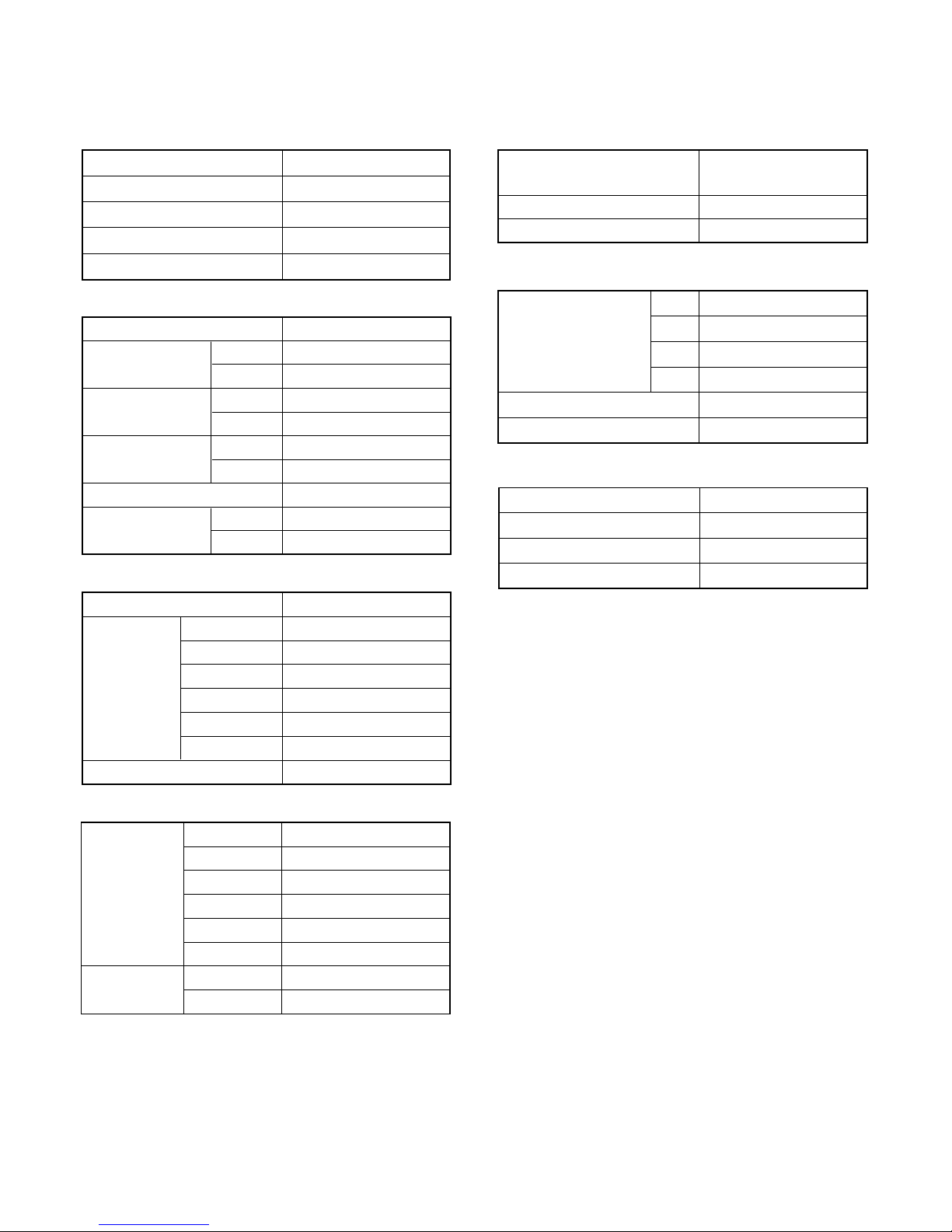
HEATING CAPACITY
POWER SUPPLY
RUNNING
CURRENT
COOLING
HEATING
10.3 A
INPUT WATTS
COOLING
HEATING
2.35 kW
E.E.R.
COOLING
HEATING
COOLING
HEATING
3.62 kW/kW
MOISTURE REMOVAL
AIR CIRCULATION
HIGH
Cooling and heating inverter
AW *Z24LBC
AO*Z24LBT
7.1 kW
8.5 kW
TYPE
INDOOR UNIT
OUTDOOR UNIT
COOLING CAPACITY
230 V 50 Hz
9.7 A
2.21 kW
3.0 L/hr
3.21 kW/kW
ELECTRICAL DATA
POWER SOURCE 230 V
HIGH SPEED
1,500 r.p.m. / 1,700 r.p.m.
HIGH2 1,700 r.p.m. / 1,850 r.p.m.
INDOOR UNIT
( cool / heat )
MED SPEED
1,370 r.p.m. / 1,540 r.p.m.
SUPER QUIET
1,030 r.p.m. / 1,120 r.p.m.
QUIET
1,130 r.p.m. / 1,260 r.p.m.
LOW SPEED
1,250 r.p.m. / 1,390 r.p.m.
OUTDOOR UNIT ( cool / heat )
850 r.p.m. / 900 r.p.m.
FAN MOTOR
DIMENSIONS and WEIGHT
INDOOR UNIT
H x W x D
OUTDOOR UNIT
830 x 900 x 330 mm
250 x 899 x 298 mm
INDOOR UNIT Gross / Net
H x W x D
Gross / NetOUTDOOR UNIT 70 kg / 62 kg
17.5 kg / 14 kg
REFRIGERANT CHARGE (R410A)
FULL CHARGE
2,100 g
15 m
20 m
25 m
30 m
Pipe Length
2,200 g
1,900 g
2,000 g
ADDITIONAL CHARGE
20 g/m
MAX PIPE LENGTH
30 m
COMPRESSOR
TYPE
DISCRIMINATION
REFRIGERANT
R410A 1,900 g
5KD240XAD21
Hermetic type, DC Inverter,
Twin rotary
SPECIFICATIONS
HIGH SPEED
HIGH SPEED
880 m3/hr
980 m
3
/hr
47 dB / 47 dB
43 dB / 43 dB
40 dB / 40 dB
36 dB / 36 dB
32 dB / 32 dB
53 dB / 54 dB
HIGH2 49 dB / 49 dB
HIGH2 53 dB / 54 dB
INDOOR UNIT
( cool / heat )
MED SPEED
LOW SPEED
SUPER QUIET
QUIET
OUTDOOR UNIT
( cool / heat )
NOISE LEVEL
Note :
Noise was measured in accordance with JIS standards, Japan.
"HIGH2" means when ability measurement.
01-01
Page 6

2 . DIMENSIONS
R410A
CEILING WALL type
INVERTER
Page 7
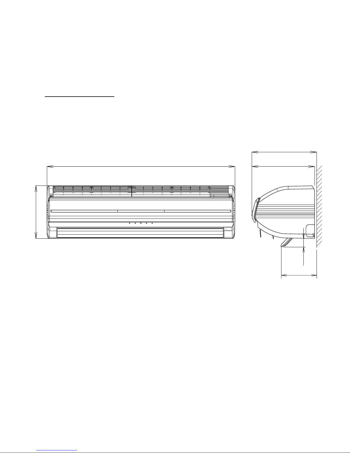
(Unit : mm)
DIMENSIONS
INDOOR UNIT
02-01
Models :
AW * Z24LBC
300
298
899
250
170
40
Page 8
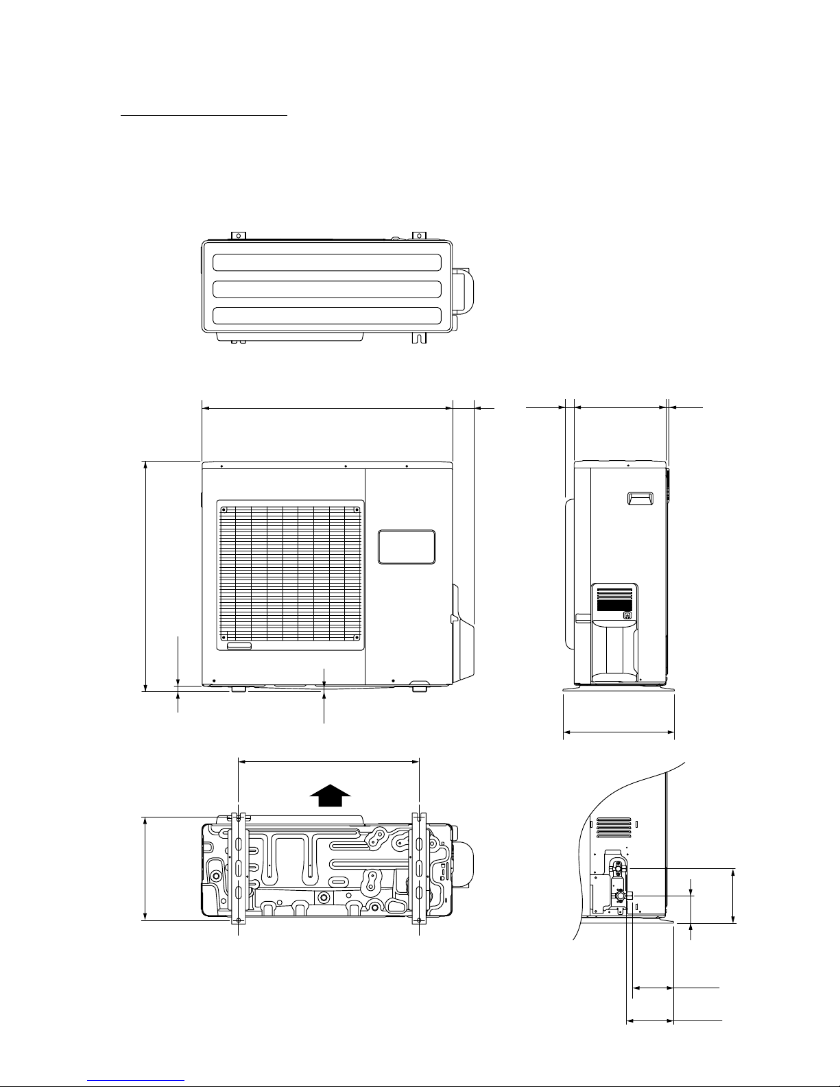
OUTDOOR UNIT
(unit : mm)
77900
830
21
9
400
33031 12
196
147
170
99
370
650
Air Flow
02-02
Models :
AO * Z24LBT
Page 9

3 . REFRIGERANT SYSTEM DIAGRAM
R410A
CEILING WALL type
INVERTER
Page 10
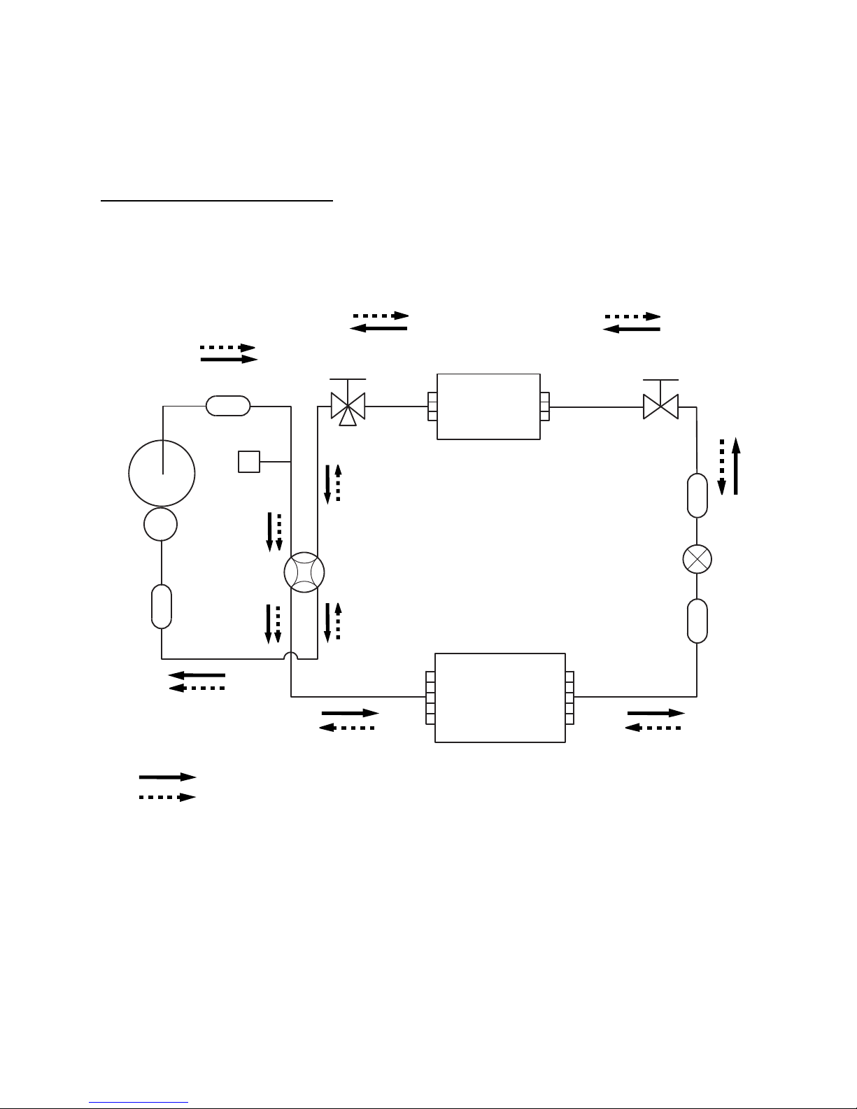
REFRIGERANT SYSTEM DIAGRAM
2-Way valve
(Small)
3-Way valve
(Large)
Strainer
Strainer
Muffler
Pressure
switch
4-Way valve
Expansion valve
Heat exchanger
( INDOOR )
Heat exchanger
( OUTDOOR )
Sub-accumulator
Compressor
Refrigerant pipe diameter
Liquid : 1/4" (6.35 mm)
Gas : 5/8" (15.88 mm)
Cooling
Heating
03-01
Models : AW * Z24LBC / AO * Z24LBT
Page 11

4 . CIRCUIT DIAGRAM
R410A
CEILING WALL type
INVERTER
Page 12
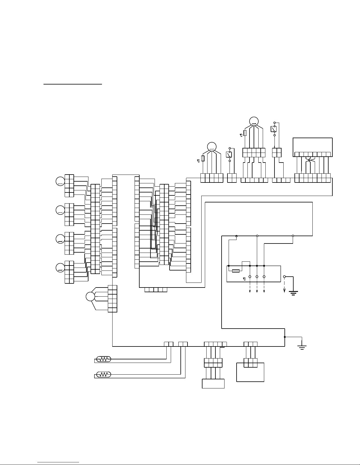
INDOOR UNIT
CIRCUIT DIAGRAM
04-01
WHITE
WHITE
WHITE
WHITE
WHITE
WHITE
WHITE
WHITE
WHITE
WHITE
WHITE
WHITE
WHITE
WHITE
WHITE
WHITE
RED
RED
RED
RED
RED
WHITE
WHITE
WHITE
WHITE
WHITE
WHITE
WHITE
WHITE
BROWN
ORANGE
YELLOW
GREEN
BLUE
PURPLE
GRAY
WHITE
BLACK
WHITE
WHITE
WHITE
WHITE
WHITE
WHITE
WHITE
WHITE
RED
WHITE
WHITE
WHITE
WHITE
WHITE
WHITE
WHITE
WHITE
RED
WHITE
WHITE
WHITE
WHITE
WHITE
WHITE
WHITE
WHITE
WHITE
RED
RED
WHITE
WHITE
WHITE
WHITE
WHITE
WHITE
WHITE
WHITE
WHITE
BLUE
YELLOW
WHITE
BLACK
RED
WHITE
WHITE
WHITE
WHITE
WHITE
WHITE
WHITE
WHITE
RED
RED
WHITE
RED
WHITE
WHITE
WHITE
WHITE
RED
WHITE
RED
WHITE
WHITE
BROWN
RED
ORANGE
YELLOW
BROWN
RED
ORANGE
YELLOW
WHITE
WHITE
WHITE
WHITE
WHITE
RED
RED
BLUE
WHITE
BLACK
RED
BLACK
BLACK
BLACK
BLACK
20
19
18
17
16
15
14
13
12
11
10
9
8
7
6
5
4
3
2
1
11
10
9
8
7
6
5
4
3
2
1
20
19
18
17
16
15
14
13
12
11
10
9
8
7
6
5
4
3
2
1
11
10
9
8
7
6
5
4
3
2
1
10
9
8
7
6
5
4
3
2
1
18
17
16
15
14
13
12
11
10
9
8
7
6
5
4
3
2
1
18
17
16
15
14
13
12
11
10
9
8
7
6
5
4
3
2
1
5
4
3
2
1
5
4
3
2
1
5
4
3
2
1
5
4
3
2
1
5
4
3
2
1
5
4
3
2
1
5
4
3
2
1
5
4
3
2
1
6
5
4
3
2
1
6
5
4
3
2
1
10
9
8
7
6
5
4
3
2
1
10
9
8
7
6
5
4
3
2
1
10
9
8
7
6
5
4
3
2
1
1234567
8
1234567
8
1234561234
1
2
1
212345
12345
12345
12345 12
12
12
345
678
12345
12345
1234
1234
123
12
3
123
12 12
CN205
TEST
CN12CN17
CN7
CN6
CN3
CN4
CN16
CN9
CN206
CN15
CN11
CN201
CN200
CN203
CN202 CN204
CN208
CN210
3
3
1
1
SW (LEFT)
SW (RIGHT)
THERMAL
FUSE 102
AIR FILTER (LEFT)
AIR FILTER (RIGHT)
THERMAL
FUSE 102
TM1
TM2
LOUVER U
LOUVER Z
LOUVER
(RIGHT-LEFT)
DIFFUSER
FAN MOTOR
CONNECTOR (WHITE)
CONNECTOR (WHITE)
CONNECTOR (RED)
CONNECTOR (RED)
ROOM TEMP. THERMISTOR
PIPE TEMP. THERMISTOR
RECEIVER PCB
UV-LED UNIT
W3
CONTROLLER PCB
F M
M
M
CONNECTOR PCB
INDICATOR PCB
M
M
M
M
TM4
WHITE
BLACK
RED
THERMAL
FUSE 102
TERMINAL
N
L
3
OUTDOOR UNIT
Models : AW * Z24LBC
Page 13
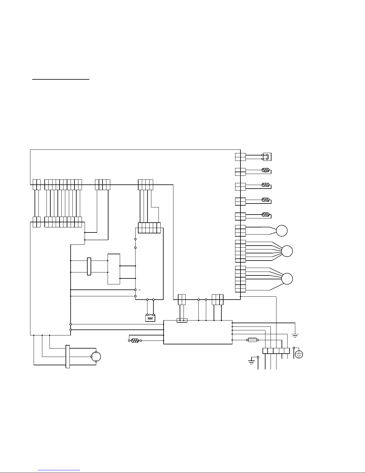
OUTDOOR UNIT
04-02
RED
RED
BROWN
BROWN
BLUE
BLUE
BLACK
BLACK
BROWN
BROWN
BLACK
BLACK
WHITE
YELLOW
ORANGE
BLUE
BROWN
RED
BROWN
YELLOW
WHITE
BLACK
RED
RED
BLACK
GREEN
BLACK
WHITE
WHITE
BLACK
PURPLE
WHITE
YELLOW
YELLOW
BLUE
BLUE
BLACK
RED
BROWN
ORANGE
BLACK BLACK
WHITE
WHITE
RED RED
ORANGE
ORANGE
BLACK
WHITE
BROWN
RED
BROWN
RED
ORANGE
YELLOW
GREEN
BLUE
PURPLE
GRAY
BLACK
WHITE
BROWN
RED
ORANGE
YELLOW
BLACK
BLACK
WHITE
GRAY
WHITE
WHITE
109
87654
321
109
87654
321
21
109
87654
321
109
87654
321
654
321
654
321
4
321
4
321
4
321
4
321
321
321
21
21
21
7
6
5
4
3
21
21
2
1
6
5
4
3
2
1
7
6
5
4
3
2
1
6
5
4
3
2
1
3
2
1
3
2
1
2
1
2
121
212
1
2
1
2
1
212
1
2
1
CN700
CN801
CN500
CN110CN1
CN400
CN200
CN11
CN60
CN61
CN62
CN64
CN90
CN40CN42
CN303 CN301
W306
W307
W302
W301
W17
W16
TM102
TM101
W303
W
W304
V
W305
U
W8
W7
W13
W12
L2 L1
+
P
N1
N2
I O
TM600
TM601
W4
R
C
S
CN100
12
W29
W28
W25
W26
W21 W20
W9
W17
W3
W18
W2
W1
W19
WHITE
WHITE
TERMINAL
FUSE 250V 25A
123LN
POWER SOURCE
TO INDOOR UNIT
FAN MOTOR
EXPANSION VALVE
4-WAY VALVE
F M
PMV
4WV
DISCHARGE TEMP. THERMISTOR
PIPE TEMP. THERMISTOR
OUTDOOR TEMP. THERMISTOR
COMPRESSOR TEMP. THERMISTOR
HIGH PRESSURE SWITCH
CHOKE COIL
POSISTOR
COMPRESSOR
C M
CONNECTOR
CONNECTOR
CAPACITOR PCB
ACTPM
I P M PCB
POWER SUPPLY PCB
CONTROLLER PCB
( MAIN PCB )
Models : AO * Z24LBT
Page 14

5 . DESCRIPTION OF EACH
CONTROL OPERATION
R410A
CEILING WALL type
INVERTER
Page 15
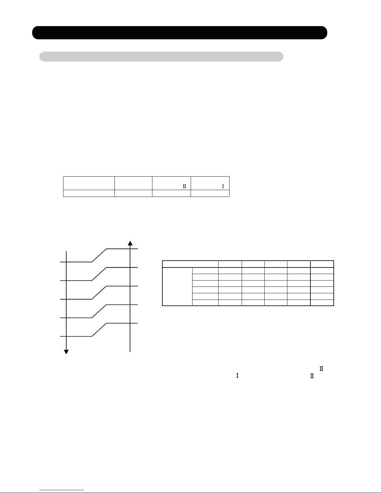
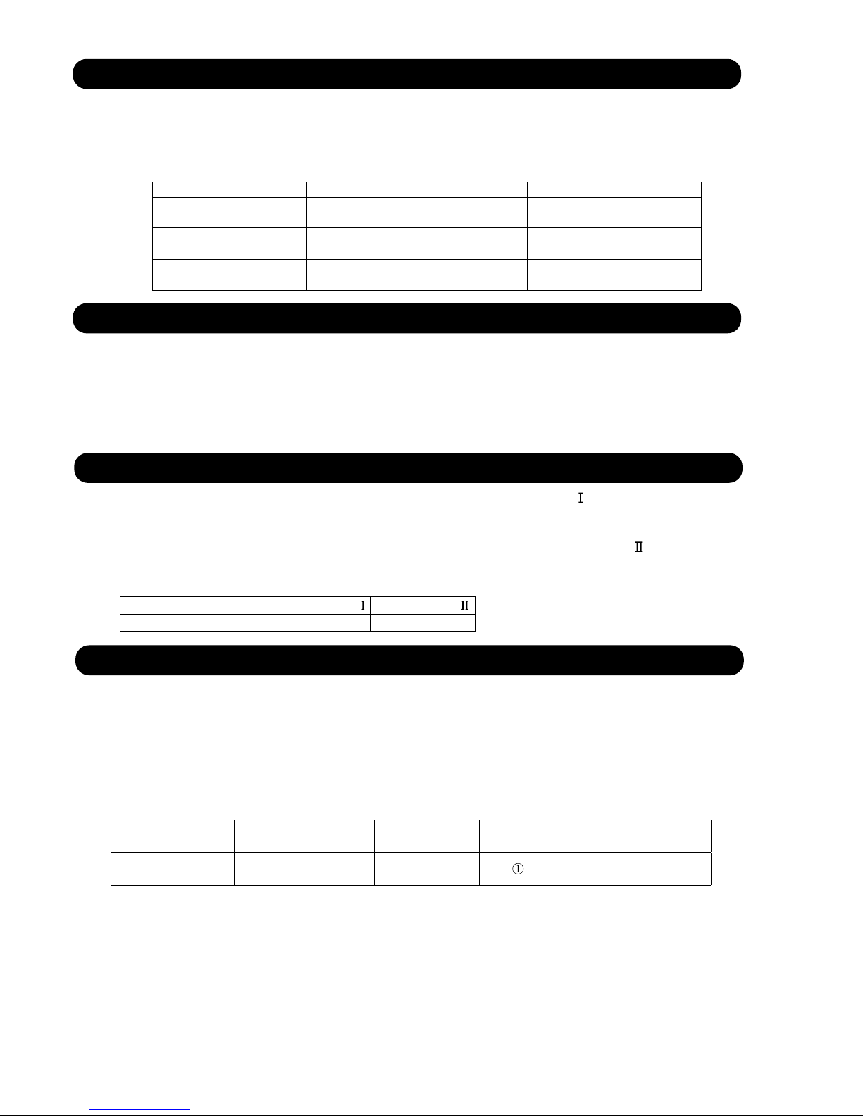
1. COOLING OPERATION
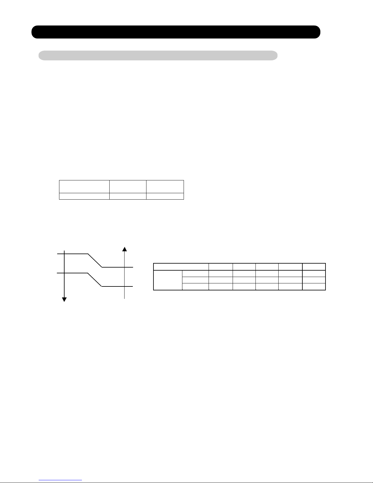
1-1 COOLING CAPACITY CONTROL
A sensor (room temperature thermistor) built in the indoor unit body will usually perceive
difference or variation between a set temperature and present room temperature, and
controls the operation frequency of the compressor.
* If the room temperature is 2°C higher than a set temperature, the compressor operation
frequency will attain to maximum performance.
minimum
frequency
maximum
frequency
maximum
frequency
AW * Z24LBC 21Hz 47Hz 63Hz
Outside air Outside air
temperature temperature
36°C
A zone
34°C
32°C
B zone
30°C
21°C
C zone
19°C
D zone
Hi Me Lo Quiet
A zone 63Hz 43Hz 37Hz 27Hz
B zone 63Hz 43Hz 37Hz 27Hz
C zone 57Hz 39Hz 33Hz 23Hz
24LBC
D zone 39Hz 31Hz 27Hz 21Hz
E zone 39Hz 31Hz 27Hz 21Hz
F zone 39Hz 31Hz 27Hz 21Hz
S-Quiet
25Hz
25Hz
21Hz
21Hz
21Hz
21Hz
( Table 1 : Compressor Frequency Range )
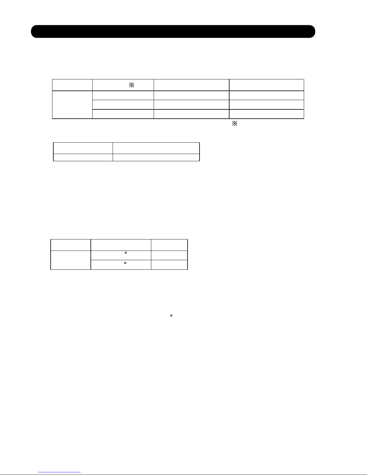
When the compressor operates for 30 minutes continuously at over the maximum frequency ,
the maximum frequency is changed from Maximum Frequency to Maximum Frequency .
The room temperature is controlled 1°C lower than the setting temperature for 40 minutes
after starting the operation.
After 40 minutes, it is controlled based on the normal setting temperature.
05-01
E zone
F zone
10°C
0°C
12°C
2°C
* When the room temperature is between +2°C to -2.5°C of the setting temperature,
the compressor frequency is controlled within the range shown in Table1.
However, the maximum frequency is limited in the range shown in Figure 1 based on the
fan speed mode and the outdoor temperature.
* If the room temperature is 2.5°C lower than a set temperature, the compressor will be
stopped.
( Fig.1 : Limit of Maximum Frequency based on Outdoor Temperature )
Page 16
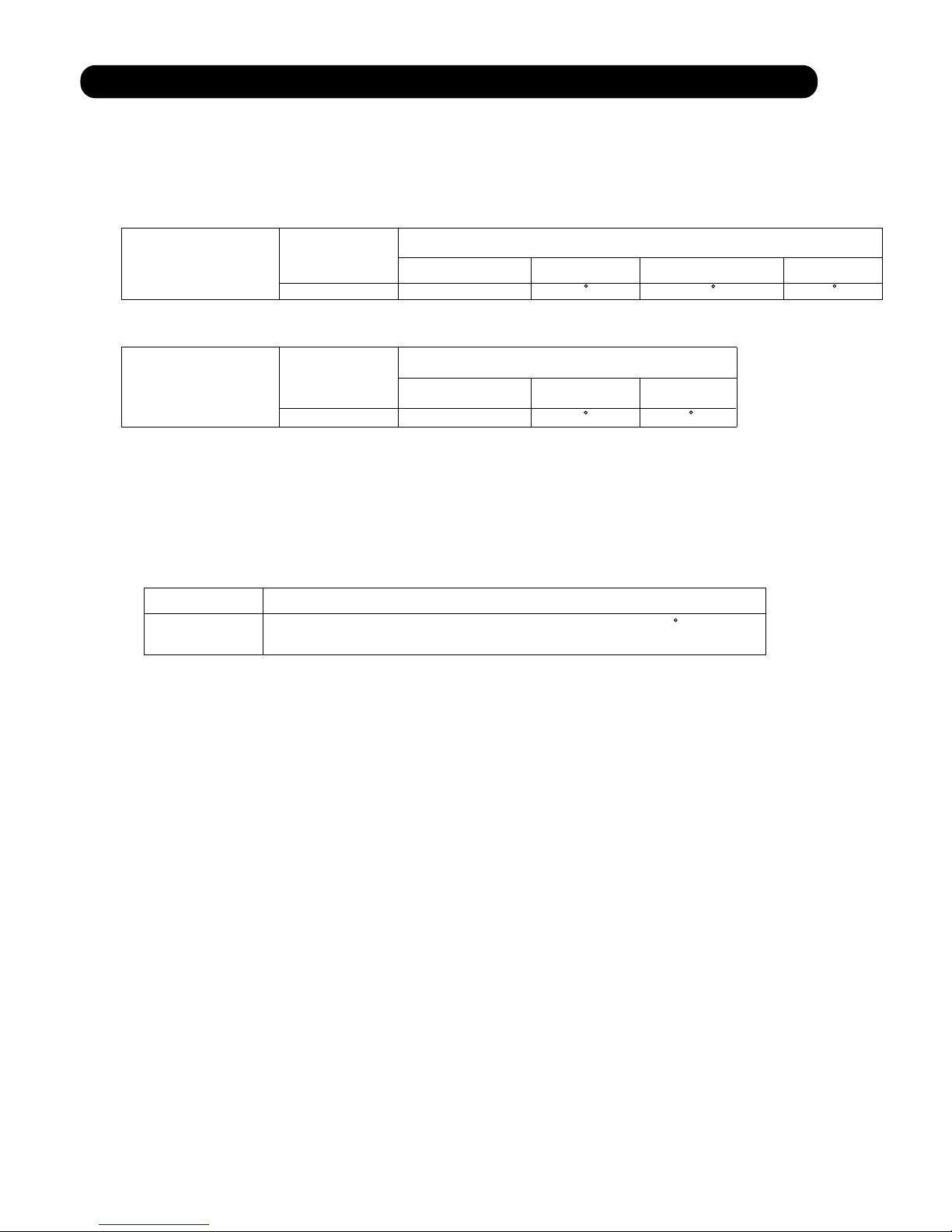
2. HEATING OPERATION
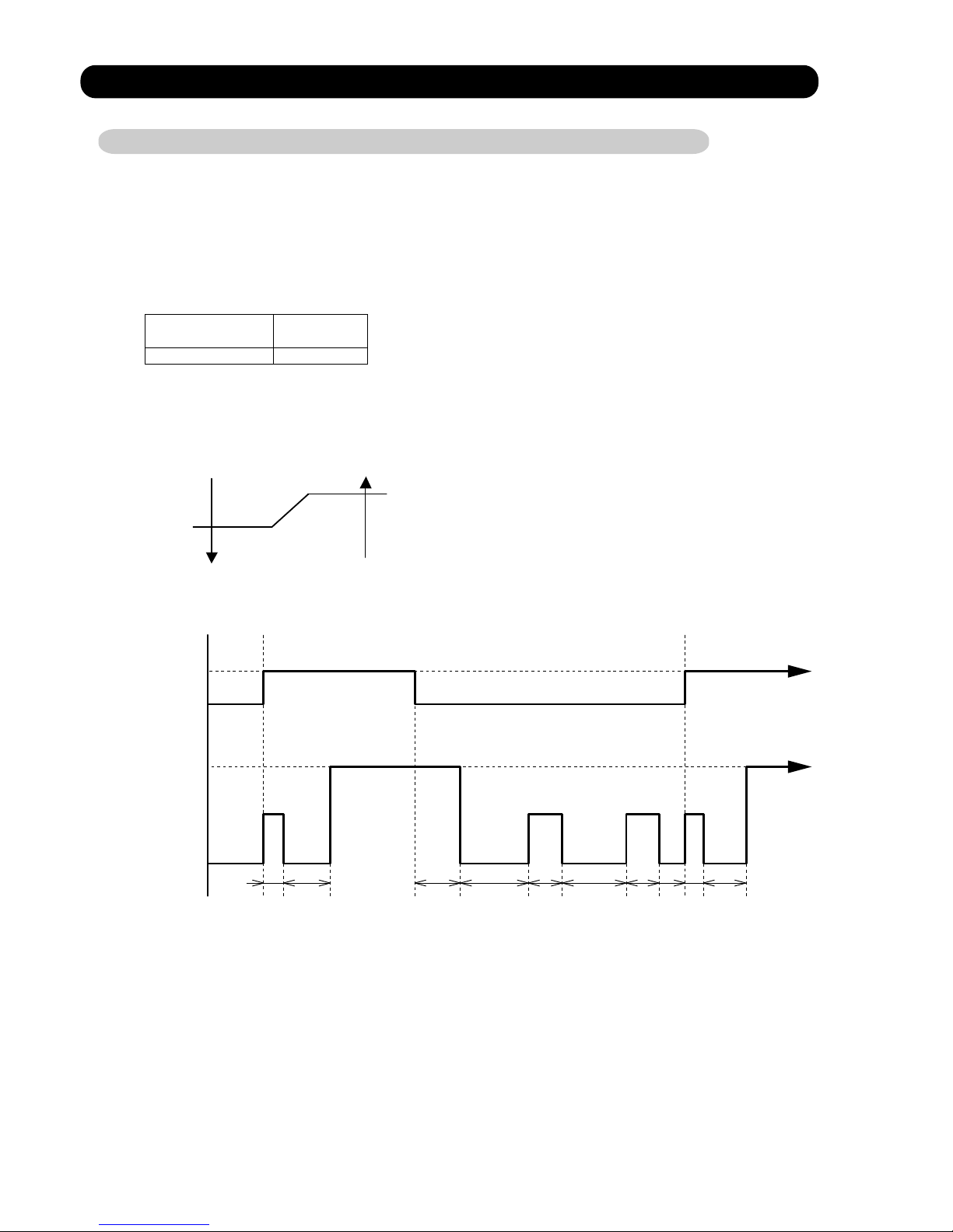
2-1 HEATING CAPACITY CONTROL
A sensor (room temperature thermistor) built in the indoor unit body will usually perceive
difference or variation between a set temperature and present room temperature, and
controls the operation frequency of the compressor.
* If the room temperature is lower by 3°C than a set temperature, the compressor operation
frequency will attain to maximum performance.
* If the room temperature is higher 2.5°C than a set temperatire, the compressor will be
stopped.
minimum
frequency
maximum
frequency
AW * Z24LBC 21Hz 87Hz
Outside air Outside air
temperature temperature
19°C
C zone
17°C
14°C
B zone
12°C
A zone
Hi Me Lo Quiet
A zone 87Hz 63Hz 51Hz 49Hz
B zone 87Hz 63Hz 51Hz 47Hz
24LBC
C zone 87Hz 63Hz 51Hz 43Hz
S-Quiet
47Hz
43Hz
39Hz
* When the room temperature is between +2°C to -3°C of the setting temperature,
the compressor frequency is controlled within the range shown in Table2.
However, the maximum frequency is limited in the range shown in Figure 2 based on the
fan speed mode and the outdoor temperature.
( Table 2 : Compressor Frequency Range )
( Fig.2 : Limit of Maximum Frequency based on Outdoor Temperature )
* The room temperature is controlled 2°C higher than the setting temperature for 60 minutes
after starting the operation.
After 60 minutes, it is controlled based on the normal setting temperature.
05-02
Page 17
3. DRY OPERATION
3-1 INDOOR UNIT CONTROL
The compressor rotation frequency shall change according to the temperature, set temperature,
and room temperature variation which the room temperature sensor of the indoor unit body has
detected as shown in the Table 3. However, after the compressor is driven, the indoor unit shall
run at operation frequency of 58Hz, for a minute.
Operating
frequency
AW * Z24LBC 23Hz
room room
temperature temperature
compressor ON
Ts+1.5°C
Ts+0.5°C
compressor OFF
Compressor
ON
OFF
Indoor fan
Dry air flow
S-Lo
OFF
( Table 3 : Compressor frequency )
( Fig.3 : Compressor Control based on Room Temperature )
( Fig.4 : Indoor Fan Control )
05-03
10 30 60 180 60 180 60 10 30
(SEC)
Page 18
4. AUTO CHANGEOVER OPERATION
When the air conditioner is set to the AUTO mode by remote control, operation starts in the optimum
mode from among the HEATING, COOLING, DRY and MONITORING modes. During operation, the
optimum mode is automatically switched in accordance with temperature changes. The temperature
can be set between 18°C and 30°C in 1°C steps.
.When operation starts, only the indoor and outdoor fans are operated for 1 minute. After 1 minute,
the room temperature and outside air temperature are sensed and the operation mode is
selected in accordance with the table below.
C zone
32°C
B zone
-10°C
A zone
( Table.4 Operation mode selection table)
Outside air temperature (To)
Room temperature (Tb)
A zone B zone C zone
Tb > Ts+2°C
Tb < Ts - 2°C
Monitoring
Cooling
(automatic dry)
Cooling
(automatic dry)
Ts+2°C Tb Ts - 2°C
Monitoring Monitoring Monitoring
Heating Heating Monitoring
.When COOING was selected at , the air conditioner operates as follow:
The same operation as COOLING OPERATION of item 1 above is performed.
When the room temperature has remained at (set temperature -1°C) for 8 minutes, operation is
automatically switched to DRY and the same operation as DRY OPERATION of item 3 above
is performed.
If the room temperature reaches (set temperature +2°C during DRY operation, operation returns to
COOLING operation.
.When HEATING was selected at , the same operation as HEATING OPERATION of item 2
above is performed.
When the compressor was stopped for 6 consecutive minutes by the temperature control function
after the COOLING or HEATING operation mode was selected at above, operation is switched
to MONITORING and the operation mode is selected again.
1
1
2
3
1
4
1
( Fig.5 : Outside air temperature zone selection )
05-04
Page 19

5. INDOOR FAN CONTROL
(1).Fan speed
( Table 5 : Indoor Fan Speed )
Except S-Quiet
(2).FAN OPERATION
The airflow can be switched in 5 steps such as AUTO, QUIET, LOW, MED, HIGH, while the indoor
fan only runs.
When Fan mode is set at (Auto), it operates on (MED) Fan Speed.
AW * Z24LBC
Operation mode Air flow mode Speed (rpm)
Hi 1,700
Me+ 1,610
Me 1,510
Lo 1,390
Quiet 1,260
S-Quiet
S-Quiet
S-Quiet
1,120
Cool air
prevention
850
Heating
S-Lo 480
Hi 1,500
Me 1,370
Lo 1,250
Cooling
Fan
Quiet
1,030
1,130
Dry
1,030
05-05
1,130
Page 20
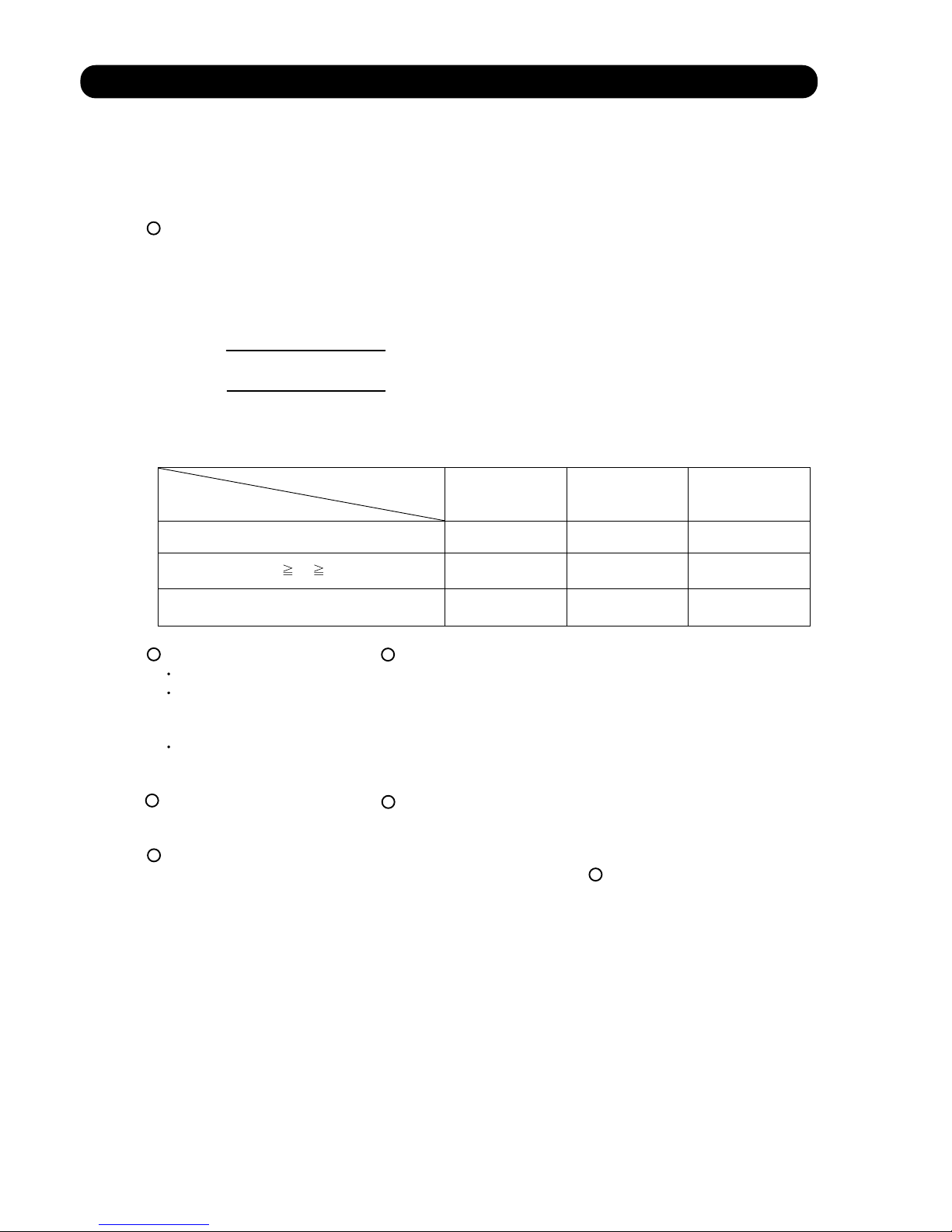
(3).COOLING OPERATION
Switch the airflow [AUTO], and the (Fig.6)
indoor fan motor will run according
airflow change - over ( Cooling:AUTO )
to a room temperature, as shown in
When the room
Figure 6.
temperature rises
On the other hand, if switched in
[HIGH]
[QUIET], the indoor motor
+2.5°C
will run at a constant airflow of [COOL]
operation modes QUIET, LOW, MED,
HIGH, as shown in Table 5.
+1.5°C
+1°C
LOW mode
When the room
temperature lowers
(Room temperature) D (Setting temperature)
(4).DRY OPERATION
(5).HEATING OPERATION
Switch the airflow [AUTO], and the (Fig.7)
indoor fan motor will run according
airflow change - over ( Heating:AUTO)
to a room temperature, as shown in
When the room
Figure 7. temperature rises
On the other hand, if switched
LOW mode
[HIGH]
[QUIET], the indoor motor -1°C
will run at a constant airflow of [HEAT]
-1.5°C
operation modes QUIET, LOW, MED,
HIGH, as shown in Table 5.
-2°C
-2.5°C
MED + mode
When the room
temperature lowers
(Room temperature) D (Setting temperature)
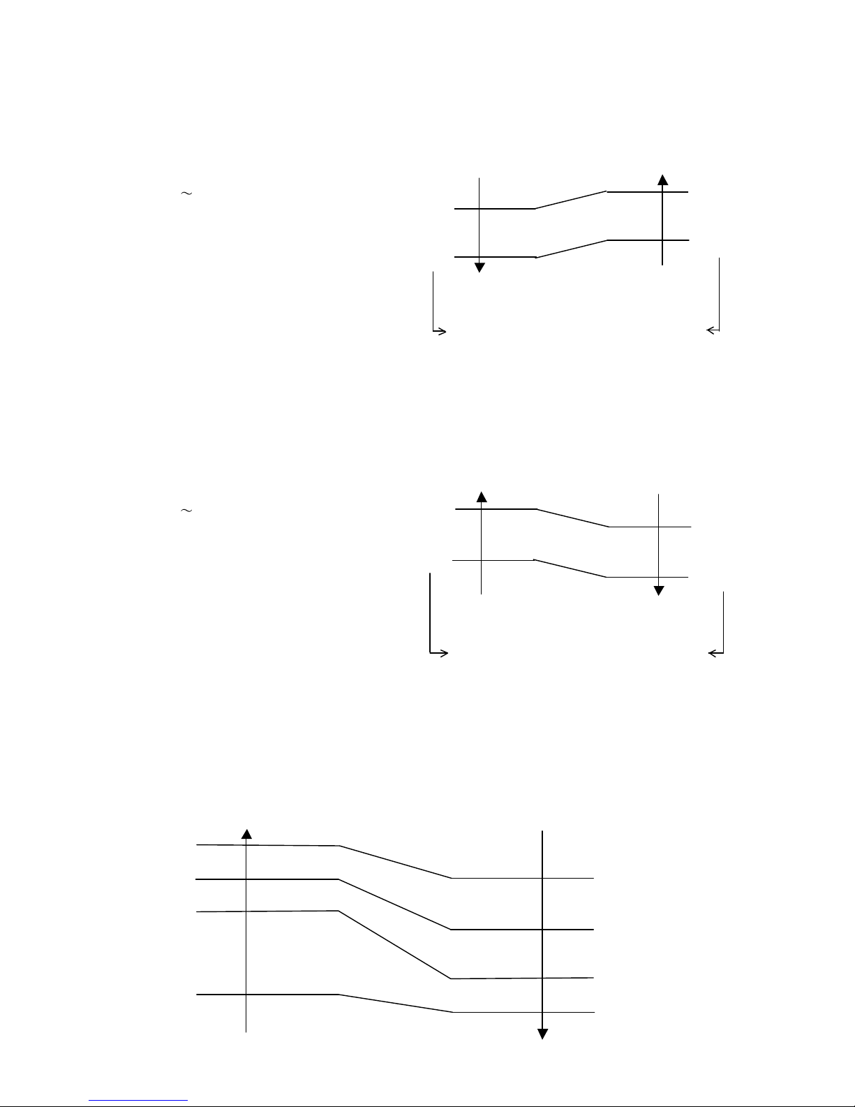
(6).COOL AIR PREVENTION CONTROL (Heating mode)
Indoor heat exchanger Indoor heat exchanger
temperature temperature
47°C
Hi
40°C
Me+
37°C
Lo
Cool air prevention
30°C
S-Lo
Refer to the table 4.
Durring the dry mode operation, the fan speed
setting can not be changed.
The maximum value of the indoor fan speed is set as shown in Figure 8, based on the detected
temperature by the indoor heat exchanger sensor on heating mode.
(Fig.8 : Cool Air Prevention Control)
05-06
40°C
28°C
32°C
34°C
HIGH mode
MED mode
+2°C
MED mode
Page 21
6. OUTDOOR FAN CONTROL
(1). Fan speed
Zone
AW * Z24LBC
Heating
AW * Z24LBC
900/780/700/550/450rpm
Table 6 : Fan speed (Cooling, Dry)
Table 7 : Fan speed (Heating)
The outdoor fan speed is changed in the range of the speed shown in the above table,
based on the frequency of the compressor.
(When the compressor frequency increases, the outdoor fan speed is also changed to
higher speed. If the compressor frequency decreases, the outdoor fan speed is changed
to the lower speed as well.)
After starting up the outdoor fan, it operates with the following speed for initial 20 seconds.
*
Table 8 : Fan speed when starting up Outdoor fan
*
After operating the defrost control function on heating mode, its speed becomes 1,000rpm
regardless of the compressor frequency.
However, it returns to the normal speed control when the defrosting operation does not function
for 240 minutes after releasing the defrost operation or when the outdoor temperature sensor
detection value becomes higher than 5 C.
05-07
A to D
Cooling
850/780/700/500rpm
500/250/200rpm
320/250/200rpm
Dry
550/450rpm
500/250/200rpm
320/250/200rpm
Outdoor temperature
AW * Z24LBC
Speed
500rpm
200rpm
Over than 12 C
Less than 12 C
E
F
Refer to Fig.1
Page 22

7. LOUVER CONTROL
05-08
(1). LOUVER CONTROL
Each time the button is pressed, the air direction range will change as follow:
Cooling / Dry mode
Heating mode
Fan mode
Use the air direction adjustments within the ranges shown above.
The vertical airflow direction is set automatically as shown, in accordance with the type of operation
selected.
Cooling / Dry mode
Horizontal flow
Heating mode
Downward flow
When the temperature of the air being blown out is low at the start of heating operation or during
defrosting, the airflow direction temporarily becomes
to prevent cold air being blown onto the body.
During Monitor operation in AUTO CHANGEOVER mode, the airflow direction automatically
becomes
.
(Function Range)
(Fig 9: Air Direction Range)
(Operation Range)
When the indoor control interface device receives a control signal light from the remote control,
it will actuate, the step motor according to the control signal, and set the louver to each position.
In addition, if the air conditioner is stopped, vertical louver will be closed automatically.
Vertical Air Direction Adjustment
6
Each time the button is pressed, the air direction range will change as follow:
(Function Range)
Horizontal Air Direction Adjustment
7
1
8
778
8
5
6
Cooling mode / Dry mode / Fan mode( )
Heating mode / Fan mode(
)
(2). SWING OPERATION
When the swing signal is received from the remote controller, the vertical louver starts to swing.
(Swinging Range)
When the indoor fan is at S-Lo or Stop mode, the swinging operation is interrupted
and it stops at either right end or left end.
14
1
4
5
8
88
To select Vertical Airflow Swing Operation
To select Horizontal Airflow Swing Operation
When the swing signal is received from the remote controller, the horizontal louver starts to swing.
All mode :
(Swinging Range)
3
1
When the indoor fan is S-Lo or Stop mode, the swinging operation is interrupted
and it stops at either upper end or bottom end.
To select Vertical and Horizontal Airflow Swing Operation
When the horizontal swing signal is input from remote control, the combination of the vertical
and horizontal swing operation is performed.
Page 23
8. COMPRESSOR CONTROL
(1). OPEARTION FREQUENCY RANGE
The operation frequency of the compressor is different based on the operation mode as
shown in the table 9.
Cooling Heating
Min Max Min Max
Dry
AW * Z24LBC 21Hz 75Hz 21Hz 87Hz 23Hz
AW * Z24LBC 40Hz 59Hz
(Table 9 : Compressor Operation Frequency Range)
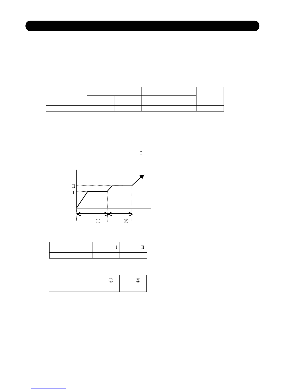
(2). OPEARTION FREQUENCY CONTROL AT START UP
The compressor frequency soon after the start-up is controlled as shown in the figure 10.
(Fig.10 : Compressor Control at Start-up )
Time
Time
(Frequency)
(Time)
Frequency
Frequency
Time Time
Frequency
Frequency
05-09
AW * Z24LBC
60sec 40sec
AW * Z24LBC
Page 24
9. TIMER OPEARTION CONTROL
(1). OPEARTION FREQUENCY RANGE
The table 9 shows the available timer setting based on the product model.
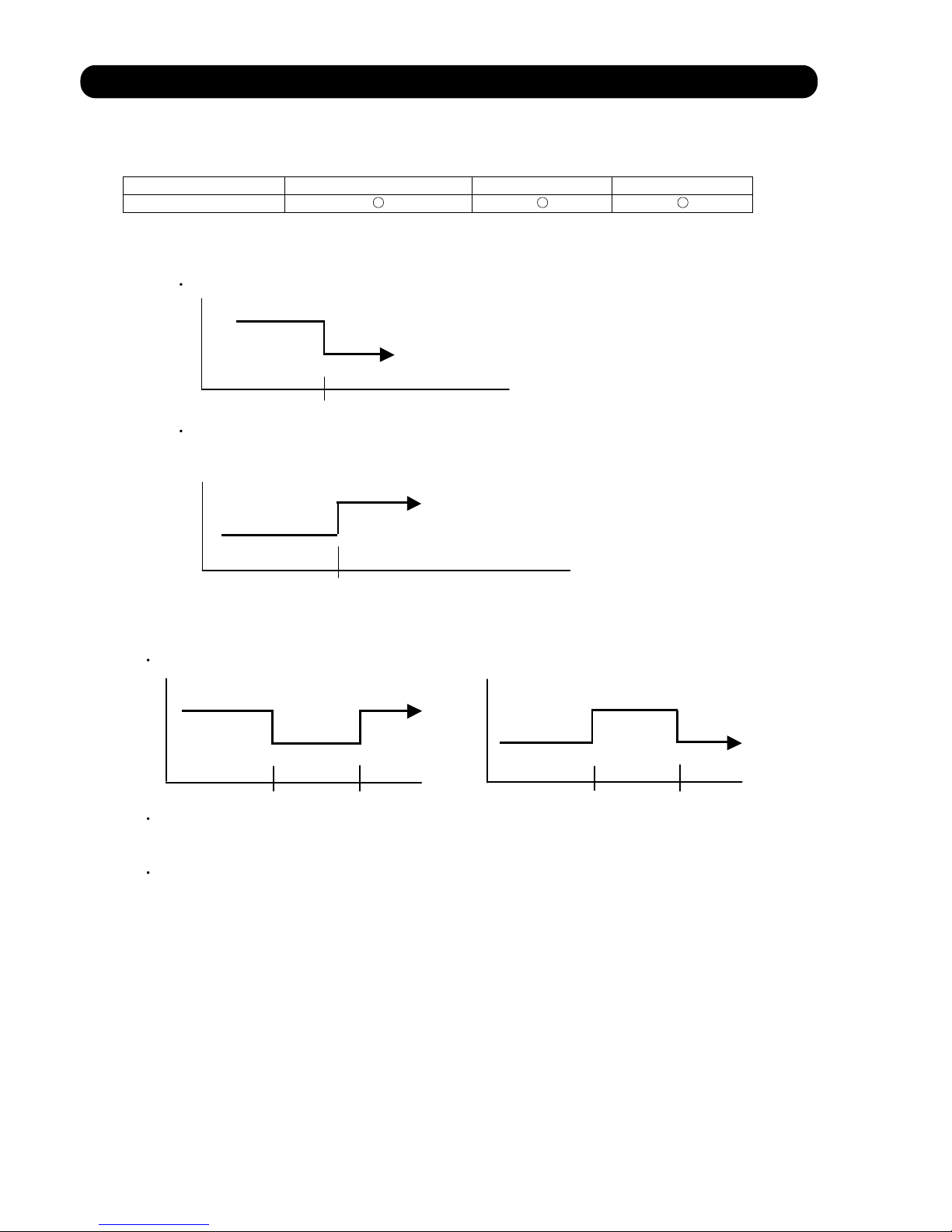
ON TIMER / OFF TIMER PROGRAM TIMER SLEEP TIMER
AW * Z24LBC
OFF timer : When the clock reaches the set time, the air conditioner will be turned off.
Operation mode
Stop mode
Set time of timer
ON timer : When the clock reaches the set time, the air conditioner will be turned on.
Operation mode
Stop mode
Set time of timer
The program timer allows the OFF timer and ON timer to be used in combination one time.
Operation mode
Operation will start from the timer setting (either OFF timer or ON timer) whichever is closest
to the clock's current timer setting. The order of operations is indicated by the arrow in the remote
control unit's display.
SLEEP timer operation cannot be combined with ON timer operation.
(Table 9 : Timer Setting)
(2). PROGRAM TIMER
Stop mode
Stop mode
Stop mode
Operation mode
Operation mode
Set time
Set time Set time Set time
05-10
Page 25
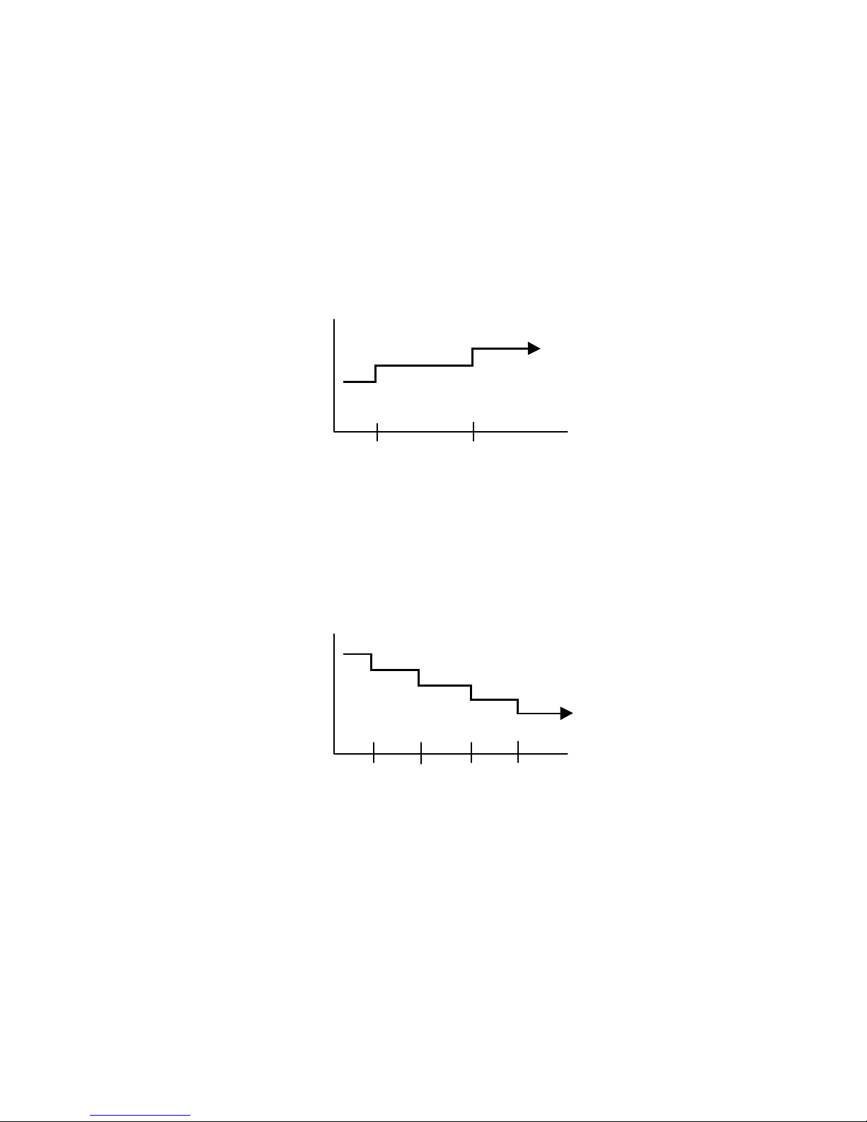
(3). SLEEP TIMER
If the sleep is set, the room temperature is monitored and the operation is stopped automatically.
If the operation mode or the set temperature is change after the sleep timer is set, the operation is
continued according to the changed setting of the sleep timer from that time ON.
Set temperature rises
( Ts : Set temperature )
Stop of operation
Set temperature lowers
( Ts : Set temperature )
Ts
Stop of operation
In the cooling operation mode
When the sleep timer is set, the setting temperature is increased 1°C.
It increases the setting temperature another 1°C after 1 hour.
After that, the setting temperature is not changed and the operation is stopped at the time
of timer setting.
Ts
+1°C
+2°C
Set
60min
In the heating operation mode
When the sleep timer is set, the setting temperature is decreased 1°C.
It decreases the setting temperature another 1°C every 30 minutes.
Upon lowering 4°C, the setting temperature is not changed and the operation stops at
the time of timer setting.
-4°C
-3°C
-2°C
-1°C
Set
30min
30min
30min
05-11
Page 26

10. ELECTRONIC EXPANSION VALVE CONTROL
The most proper opening of the electronic expansion valve is calculated and controlled under the
present operating condition based on the following values.
The compressor frequency, the temperatures detected by the discharge temperature sensor, the
indoor heat exchanger sensor, the outdoor heat exchanger sensor, and the outdoor temperature
sensor.
11. TEST OPERATION CONTROL
Under the condition where the air conditioner runs, press the test operation button of the remote
control, and the test operation control mode will appear. During test running, the operation lamp
and timer lamp of the air conditioner body twinkle simultaneously. Set the test operation mode,
and the compressor will continue to run regardless of whether the room temperature sensor detects.
The compressor won't enter operation status for 3 minutes after the compressor is stopped,
even if any operation is given.
At the time when the air conditioner is switched from the cooling mode to heating mode, the
compressor is stopped, and the four-way valve is switched in 3 minutes later after the compressor
stopped.
When the power was interrupted by a power failure, etc. during operation, the operation contents
at that time are memorized and when power is recovered, operation is automatically started with
the memorized operation contents.
When the power is interrupted and recovered during timer operation, since the timer operation time
is shifted by the time the power was interrupted, an alarm is given by blinking (7 sec ON/2 sec OFF)
the indoor unit body timer lamp.
[Operation contents memorized when the power is interrupted]
Operation mode
Set temperature
Set air flow
Timer mode and timer time
Set air flow Direction
Swing
The test operation mode is released if 60 minutes have passed after setting up the test operation.
12. PREVENT TO RESTART FOR 3 MINUTES ( 3 MINUTES ST )
13. FOUR-WAY VALVE EXTENSION SELECT
14. AUTO RESTART
05-12
AW * Z24LBC
Pulse range
40 480 pulse
(1) Pulse range of EEV
(2) The EEV is set up at 480 pulses when the compressor is stopped.
(3) Intialization (Input of 528 pulses toward closing direction) is operated under the
following condition.
* When the power is turned on.
* 3 hours has passed since the last initialization, and 3 minutes has passed after
the compressor stop.
(If 12 hours has passed since the last initialization, the compressor is compulsorily
stopped.)
Page 27
15. MANUAL AUTO OPERATION (Indoor unit body operation)
If MANUAL AUTO Button is set (Push a MANUAL AUTO button for 3~10 seconds), the operation
If the remote control is lost or battery power dissipated, this function will work without the remote
control.
is controlled as shown in Table 10.
OPERATION MODE Auto changeover
FAN CONT. MODE Auto
TIMER MODE Continuous
SETTING TEMP. 24°C
SETTING LOUVER Standard
SWING OFF
When the outdoor heat exchanger temperature is lower than temperature and the heating operation has
been stopped for 30 minutes, power is applied to the compressor and the compressor is heated.
(By heating the compressor, warm air is quickly discharged when operation is started.)
When operation was started, and when the outdoor temperature rises to temperature or greater, preheating
is ended.
Filter Clean is operated after a coil dry operation end.
FIlter Clean function performs disinfection and deodorization of a filter with UV lamp during filter
movement.
Unit is stopped after Filter Clean operation.
AW * Z24LBC
AW * Z24LBC
1100rpm 29Hz
(Table 10)
(No timer setting available)
17. COMPRESSOR PREHEATING
(Table 11 : Preheating Operation / Release Temperature)
Temperature
Temperature
5°C
7°C
18. COIL DRY AND CLEAN OPERATION CONTROL
The coil-dry operation functions by pressing COIL DRY button on the remote controller.
The coil-dry operation is consisted of 3 cycles of [Fan operation 3 minutes / Heating operation
2 minutes], and Fan operates for 3 minutes at last before ending the air conditioner operation.
(It takes 18 minutes to complete the coil-dry operation.)
(Table 12 : COIL-DRY Operating Functions)
Indoor Fan Speed
Compressor
Frequency
Louver
Position
Main Unit
Indication
COIL-DRY indication : ON
Other indication : OFF
05-13
Forced cooling operation
Cooling
16. FORCED COOLING OPERATION
Forced cooling operation is started when pressing MANUAL AUTO button for 10 seconds or more.
During the forced cooling operation, it operates regardless of room temperature sensor.
Operation LED and timer LED blink during the forced cooling operation. They blink for 1 second ON
and 1 second OFF on both operation LED and timer LED (same as test operation).
Forced cooling operation is released after 60 minutes of starting operation.
The FORCED COOLING OPERATION will start as shown in Table10.
COIL DRY OPERATION CONTROL
Hi
Horizontal
OFF
Room Temp is not controlled
Manual auto operation
-
Page 28
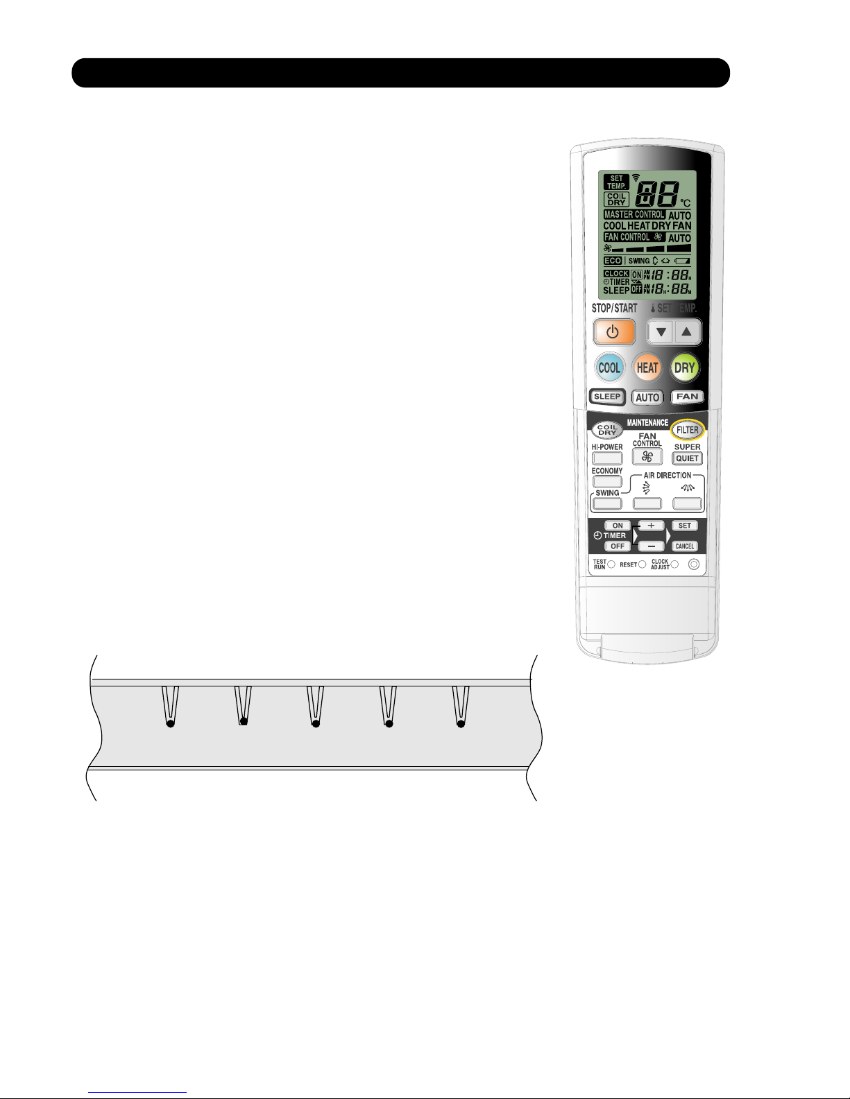
19. UV FILTER CLEANING CONTROL
1. SETTING METHOD
(1) Manual filter cleaning function
- Press [FILTER] button on remote controller to start filter cleaning.
(2) Automatic cleaning function
- Filter maintenance interval can be set at either 50 hours or 100 hours
with the remote controller ([SET TIME] button is kept pressed - refer to
the operation manual).
- When the accumulated operating time reached to the set up interval
time, the filter cleaning function automatically starts at the stop mode.
2. MAIN UNIT INDICATION
* Type of [MAINTENANCE SIGN] lamp (Red) indications on main unit.
- During the filter cleaning function
[MAINTENANCE SIGN] lamp (Red) is ON.
(It lights up only when the filter is functioning. Upon filter
function is completed, it goes off.)
- When the filter cleaning function is abnormal
[MAINTENANCE SIGN] lamp (Red) blinks (1 sec. ON / 1 sec. OFF)
- Notification of Dust box maintenance
[MAINTENANCE SIGN] lamp (Red) will light up.
It notifies the timing of Dust box maintenance. It lights up after 2,000
or 4,000 hours of operation by setting up with the auto cleaning
function time.
The red lamp will keep lighting until resetting the accumulated time,
regardless of air conditioner's operating mode.
3. REMOTE CONTROLLER CONDITION
The LCD indication does not change with [FILTER] button.
4. LIMIT SWITCH CONDITION FOR THE FILTER LOCATION DETECTION.
- Limit switch ON - On filter function, the filter is stopped on the way.
- Limit switch OFF - The filter is correctly installed, or The filter is not installed.
05-14
MAINTENANCE SIGN
TIMER OPERATION HI-POWER
SUPER QUIET
Page 29

5. OPERATING FUNCTION
- UV filter cleaning function
UV LED is turned on during the filter cleaning operation to remove bacteria or to deodorize.
< Condition to light up UV-LED >
UV-LED is lighted up after 5 seconds of starting the filter cleaning operation.
If error is occurred during the filter operation, it is turned off.
6. PROTECTING FUNCTIONS
(1) Automatic filter retracting function
Under following conditions, the filter moves toward retracting direction until the limit switch
turns OFF.
- The limit switch is kept ON for 2 seconds when the power is turned on.
- The limit switch turns ON from OFF and it is kept ON for 2 seconds when the air conditioner
is in operating or stop mode.
> If the air conditioner is in operating mode, it does not stop the operation and functions the
filter.
(2) Filter mounting error protection
(a) Filter come out mounting error
(b) Filter retract mounting error
If above error occurs, it is memorized in EEPROM (Error history).
Error is indicated with blinking [MAINTENANCE SIGN] lamp (Red) for 1 sec. ON / 1 sec. OFF.
(3) Filter cleaning forced stop function when Dust box maintenance notification is in operation.
* When [MAINTENANCE SIGN] LED (Red) is ON, following functions do not work until reset
button will be pressed.
- Auto cleaning / Manual filter cleaning function
- Filter auto retract function
- Forced filter cleaning function, Off timer operating time auto cleaning.
* This protecting function can be released by pressing [MAINTENANCE/MANUAL AUTO]
button.
(4) Filter cleaning stepping motor temperature rise protection
Filter cleaning can be operated continuously up to 3 times.
(If it is operated 3 times continuously, it stops filter cleaning function for 3 minutes.)
(5) Forced filter cleaning protection for the continuous operation
When the operation time of air conditioner reaches to 200 hours, the operation is temporarily
stopped, and the filter cleaning is performed. Upon completion of the filter cleaning, it resumes
operation.
(6) Auto cleaning function protection for OFF Timer operating time
If the filter cleaning does not operate after 100 hours of air conditioner operating time and it is
reached to 150 hours, the filter cleaning function starts to operate at the time of stopping
operation by OFF Timer time up
05-15
Page 30
20. DEFROST OPERATION CONTROL
(1). CONDITION OF STARTING THE DEFROST OPERATION
The defrost operation starts when the outdoor heat exchanger temperature sensor detects
the temperature lower than the values shown in Table 15.
(Table 15 : Condition of starting Defrost Operation)
AW * Z24LBC
AW * Z24LBC
AW * Z24LBC
1 time defrosting
after starting
operation
ST
Defrosting after 2
time upon starting
operation
ND
Compressor operating time
Less than 17 minutes 17 to 60 minutes
60 minutes to 4 hours
After 4 hours
Does not operate
- 9 C
- 5 C
- 3 C
Less than 35 minutes
35 minutes to
4 hours
Does not operate
Compressor operating time
After 4 hours
- 3 C
- 6 C
(2). CONDITION OF THE DEFROST OPERATION COMPLETION
Defrost operation is released when the conditions become as shown in Table 16.
(Table 16 : Defrost Release Condition)
Release Condition
Outdoor heat exchanger temperature sensor value is higher than 13 C or
Compressor operation time has passed 15 minutes.
05-16
Page 31

Defrost Flow Chart
The defrosting shall proceed by the integrating operation time and outdoor heat exchanger
temperature as follows.
(Not defrosted for 10 minutes)
(In case of 1st defrost) (In case of 2nd and later defrost)
Compressor OFF
Outdoor fan motor OFF
30 sec later four - way valve OFF
36 sec later compressor ON
Heating operation start : Compressor ON
Compressor integrating
operation:
Over 17 minutes to
below 60 minutes
Compressor integrating
operation:
Over 60 minutes to
below 240 minutes
Compressor integrating
operation:
Over 240 minutes
Compressor integrating
operation:
Over 35 minutes to
below 240 minutes
Compressor integrating
operation:
Over 240 minutes
Outdoor heat exchanger
temperature:
Below
-9°C
Outdoor heat exchanger
temperature:
Outdoor heat exchanger
temperature:
Outdoor heat exchanger
temperature:
Outdoor heat exchanger
temperature:
Defrost start
Defrost Indicator:
[Operation lamp]
7 sec ON / 2 sec OFF
Outdoor heat exchanger temperature:
Over 13°C
or
Compressor ON time:
Over 15 minutes
Defrost end
Below -5°C
Below -3°C
Below -6°C
Below -3°C
05-17
Page 32

21. OFF DEFROST OPEARTION CONTROL
(1). OFF DEFROST OPERATION CONDITION
When operation stops in the [Heating operation] mode, if frost is adhered to the outdoor unit heat
exchanger, the defrost operation will proceed automatically. In this time, if indoor unit operation
lamp flashes slowly (7 sec ON / 2 sec OFF), the outdoor unit will allow the heat exchanger to defrost,
and then stop.
In heating operation, the outdoor heat exchanger temperature is less than -4°C, and
compressor operation integrating time lasts for more than 30 minutes.
AW * Z24LBC
OFF Defrost Flow Chart
Heating operation stop
Outdoor heat exchanger temperature:
Below -4°C
and
Compressor integrating operation:
Over 30 minutes
Defrost start
Defrost Indicater:
[Operation lamp]
Outdoor heat exchanger temperature:
Over 13°C
or
Compressor ON time:
Over 15 minutes
Defrost end
(2). OFF DEFROST END CONDITION
Release Condition
Outdoor heat exchanger temperature sensor value is higher than 13°C or
Compressor operation time has passed 15 minutes.
7 sec ON / 2 sec OFF
05-18
Page 33

22. VARIOUS PROTECTIONS
(1). DISCHARGE GAS TEMPERATURE OVERRISE PREVENSION CONTROL
The discharge gas thermosensor (discharge thermistor : Outdoor side) will detect discharge gas
temperature.
AW * Z24LBC 104°C 101°C 110°C
AW * Z24LBC
AW * Z24LBC
7.0A / 6.5A
9.5A / 9.0A
11.5A /11.0A
When the discharge temperature becomes higher than Temperature ,the compressor frequency
is decreased 20 Hz, and it continues to decrease the frequency for 20 Hz every 120 seconds until
the temperature becomes lower than Temperature .
When the discharge temperature becomes lower than Temperature ,the control of the control of the
compressor frequency is released.
When the discharge temperature becomes higher than Temperature ,the compressor is stopped
and the indoor unit LED starts blinking.
(Table 15 : Discharge Temperature Over Rise Prevension Control / Release Temperature)
Temperature
Temperature
Temperature
(2). CURRENT RELEASE CONTROL
The compressor frequency is controlled so that the outdoor unit input current does not exceeds
the current limit velue that was set up with the outdoor temperature.
The compressor frequency returns to the designated frequency of the indoor unit at the time
when the frequency becomes lower than the release value.
(Table 16 : Current Release Operation Value / Release Value)
[ Cooling / Dry ]
OT : Outdoor Temperature
OT : Outdoor Temperature
05-19
10.5A / 10.0A
13.0A / 12.5A
15.0A / 14.5A
17.0A / 16.5A
OT (Control / Release)
17°C
12°C
5°C
46°C
40°C
OT (Control / Release)
[ Heating ]
Page 34

(3). ANTIFREEZING CONTROL (Cooling and Dry mode)
The compressor frequency is decrease on cooling & dry mode when the indoor heat exchanger
temperature sensor detects the temperature lower than Temperature .
Then, the anti-freezing control is released when it becomes higher than Temperature .
A-D
E,F
(Table 17 : Anti-freezing Protection Operation / Release Temperature)
TemperatureTemperature
4°C
4°C
7°C
13°C
(4). COOLING PRESSURE OVERRISE PROTECTION
(Table 18 : Cooling Pressure Over Rise Protection Function Temperature)
When the outdoor unit heat exchange sensor temperature rises to temperature or greater, the
compressor is stopped and trouble display is performed.
AW * Z24LBC 67°C
Temperature
(5). HIGH TEMPERATURE RELEASE CONTROL ( HEATING MODE )
On heating mode, the compressor frequency is controlled as following based on the
detection value of the indoor heat exchanger temperature sensor.
05-20
[AW * Z24LBC ]
59Hz or greater
57Hz
31
57Hz
23 29Hz 21Hz
21Hz
OFF
Indoor heat exchange
temperature
[ Control System ]
Temperature
Temperature
Refer to below
Temperature
Temperature
The compressor frequency is
precisely controlled so that
it does not exceeds Temperature .
It returns to the normal operation
Compressor Operation
Frequency down every 120 sec
AW * Z24LBC 55°C
Temp
Temp Temp Temp
53°C 52°C 50°C
Zone
Refer to Fig.1
Page 35

05-21
(6). COMPRESSOR TEMPERATURE PROTECTION
When the compressor temperature sensor detects higher than Temperature in the table below,
the compressor is stopped. The protection is released when the compressor temperature sensor
detects Temperature in the table below after 3 minutes of compressor stop.
(Table 22 :Operating Temperature of Compressor Protection)
Temperature
Temperature
AW * Z24LBC
(7). HIGH PRESSURE PROTECTION
When the pressure switch becomes OFF (open : higher than 609.2 psi /4.2 Mpa), the compressor is
stopped. It is released when the pressure switch becomes ON (close : lower than 464.1 psi/3.2 Mpa)
after 3 minutes of compressor stop.
120 C
80 C
Page 36

6 . REFRIGERANT CAUTION -R410A-
R410A
CEILINGWALL type
INVERTER
Page 37

1. R410A TOOLS
Gauge manifold . . . . . . . . . . . . . . . . . . . . . (Fig.4-1)
Since the normal pressure is high, the connection pipe size
is also different.
Charge hose . . . . . . . . . . . . . . . . . . . . . . . (Fig.4-2)
Refrigerant cylinder . . . . . . . . . . . . . . . . . (Fig.4-3)
Confirm the refrigerant type before charging. Always
charge liquid-phase refrigerant.
Electronic balance for refrigerant
charging . . . . . . . . . . . . . . . . . . . . . . . . . . .
(Fig.4-4)
Electronic balance is recommended as in the case of
R410A.
Vacuum pump with adapter to prevent
reverse flow . . . . . . . . . . . . . . . . . . . . . . . .
(Fig.4-5)
Conventional pump can be used.
Vacuum holder . . . . . . . . . . . . . . . . . . . . . (Fig.4-6)
Conventional pump can be used if adapter for preventing
vacuum pump oil from flowing back is used.
Gas leakage tester . . . . . . . . . . . . . . . . . . (Fig.4-7)
Exclusive for HFC
Refrigerant cleaner . . . . . . . . . . . . . . . . . . (Fig.4-8)
Brown paint as designated by the ARI, USA
Flare tool . . . . . . . . . . . . . . . . . . . . . . . . . . (Fig.4-9)
Torque wrench . . . . . . . . . . . . . . . . . . . . (Fig.4-10)
Refrigerant recovering
equipment (Collector) . . . . . . . . . . . . . .
(Fig.4-11)
The type which can be used for any refrigerant is available
Nitrogen cylinder . . . . . . . . . . . . . . . . . . . (Fig.4-12)
This prevents an oxide film from forming in the pipe silveralloy brazing work by turning the air out of the pipe and
preventing the inside combustion.
Safety charger . . . . . . . . . . . . . . . . . . . . . (Fig.4-13)
It is always compulsory to change the liquid, because
R410A is a mixed refrigerant and there is some fear that a
mixing ratio changes. In order to avoid the refrigerant from
returning to the compressor in a liquid state, the refrigerant
can be charged instead of giving a load to the compressor
with a safety charger.
Control valve . . . . . . . . . . . . . . . . . . . . . . (Fig.4-14)
The control valve prevents the refrigerant from spouting
when it is removed, as the charging hose side and the service port side are possible to open and close at the same
time.
Thermistor vacuum gauge . . . . . . . . . . . (Fig.4-15)
To remove moisture from the refrigerating cycle completely, it is necessary to perform appropriate vacuum drying.
For that reason, vacuum conditions can be confirmed certainly.
Vacuum valve . . . . . . . . . . . . . . . . . . . . . (Fig.4-16)
This valve builts in a check valve, and it is easily possible
to vacuum a refrigerating cycle or check for degree of vacuum with it.
TOOLS AND EQUIPMENT (R410A)
Gauge Manifold
R410A
R22, R407C
High
pressure
gauge
Compond
gauge
Port size
-0.1 5.3
Mpa
-0.1 3.8
Mpa
1/2UNF
5/16"
-0.1 3.5
Mpa
-0.1 1.7
Mpa
7/16UNF
1/4"
*
1
Charge hose
R410A
R22, R407C
Normal
pressure
Port size
5.1 Mpa
27.4 Mpa
1/2UNF
3.4 Mpa
17.2 Mpa
7/16UNF
*
2
Breaking
pressure
This air conditioner used R410A.
For installation and servicing, it is necessary to prepare the
tools and machines that are different from the previous
refrigerant.
Mark shows the exclusive use for R410A.
The specification of the gauge is different due
to higher pressure.
The size of connection pipe is also different to
prevent mis-use.
The shape of flare is different for
high pressure condition.
06-01
Gas charging
Vacuuming
Piping work
Pressure control and
Circuit switching
Charge hose
Fig.4-2
Outdoor unit
Electronic charging
scale Fig.4-4
Vacuum pump Fig.4-5
Thermistor vacuum gauge Fig.4-15
Vacuum
Valve Fig.4-16
Safety charger Fig.4-13
Control Valve
Fig.4-14
Vacuum holder Fig.4-6
Leakage tester Fig.4-7
Cleaner Fig.4-8
Collector Fig.4-11
Nitrogen Cylinder
Fig.4-12
Torque wrench
Fig.4-10
Flare tool
Fig.4-9
Gauge manifold
Fig.4-1
Fig.4-3
Refrigerant cylinder
Vacuum control
Low pressure
High pressure
side
side
Page 38

2. PRECAUTION FOR INSTALLATION
06-02
Precaution for installation
The pipe must be properly pressure rated for R410A
The pipe must be an air-conditioning refrigerant pipe.
Flare and flare nuts
Diameter 1/4” (6.35mm) 3/8 ” (9.52mm) 1/2 ” (12.7mm)
Refrigerant
R410A
R22
/R407C
R410A R410A
A 9.1 9.0 13.2 13.0 16.6
16.2
B 13 12 20 15 13 20
C 12 11 16 12.5 19 16
Nut width 17 22 26 24
Always use the flare nut that is packed
with the product.
Do not use existing (for R22) pipes
•
Be sure to use new pipes when replacing
conventional (R22) model with HFC
(R407C, R410A) model.
•
If you use existing pipes, it may cause
resolution of compressor oil by remaining
mineral oil.
3/8” (15.88mm)
R410A
22
29
19.7
25
R22
/R407C
R22
/R407C
R22
/R407C
19.4
23
20
27
3/4” (19.05mm)
R410A
24
36
24
29
R22
/R407C
23.7
29
24
Material
Nominal diameter
(in)
1/4" 3/8" 1/2" 5/8" 3/4" 7/8" 1 1/8" 1 1/4" 1 1/2"1 3/8"1"
6.35 9.52 12.70 15.88 19.05 22.22 28.58 31.75 38.1034.9225.40
Outside diameter
(mm)
Wall thickness
(mm)
0.8 0.8 0.8 1.0 1.2 1.0 1.0 1.1 1.31.21.0
1) Allowable tensile stress 33 (N/mm );
>
=
2
2) Allowable tensile stress 61 (N/mm ); 3) Design pressure 4.2MPa.
>
=
2
JIS H3300-C1220T-H or equivalent
2)
COPPER
JIS H3300-C1220T-O or equivalent
1)
COPPER
3)
Pipe diameter, recommended material and wall thickness
A
C
B
Page 39

Be careful not to mix moisture and
contamination into the pipe
Moisture and contamination
in the pipe is a cause of
trouble.
Air purge
Always use a
vacuum pump
to purge air.
Refrigerant charge
Do it always from the liquid phase
side.
Don't charge from the gas phase side.
Compressor oil is changed
Be careful to handle synthetic oil, since it
resolves easily by moisture and
contamination.
Don't mix new synthetic oil and mineral oil.
It may cause trouble.
We developed new synthetic oil, since HFC
refrigerant doesn't dissolve in mineral (for R22)oil.
06-03
Page 40

3. PRECAUTION FOR SERVICING
Feature 1 Refrigerant oil is different from before.
Refrigerant oil for
New Refrigerant
Synthetic oil
Ether
Esther
Different point from
previous one
Previously it was
mineral oil.
Absorbent character
is high.
Contamination occurs
when mixed withe other
kind of oil.
Use the gauge manifold and charge hose
for New Refrigerant(HFC), which shall
be segregated from those of R22.
Attach the stop valve on the vacuum pump
and avoid the oil from reverse frow.
It is necessary to use the vacuum pump
which can obtain the high vacuum condition.
Precaution on Tools
Feature 2 New Refrigerant has Approx 1.6 times higher pressure than previous refrigerant.
R410A
High Pressure
Different point from
previous one
Diameter of Service port
has been changed from
1/4 Flare to 5/16 Flare.
It requires the gauge manifold and charge
hose exclusively for R410A.
It requires the flare tool and torque wrench
that satisfies New JIS standard.
Precaution on Tools
R410A R22
1.6 times of R22.
JIS standard of flare
process It became lager
To keep thethickness of
copper tube.
(1/4,3/3=more than 0.8mm)
Previous flare tool + flare adapter can be used as well.
06-04
Page 41

4. NEW REFRIGERANT R410A
What is HFC ?
Phase-out schedule of HCFC
according to Montreal protocol
1996 20102000 2004 2015 2020 2030
60
40
20
100
(Year)
(%)
80
(HCFC consumption of 1989) +
(CFC consumption of 1989) x 2.8%
65%
35%
10%
0.5%
started control
only service use
total abolition
100% =
0
*
06-05
Page 42

Ozone Layer depleting mechanism
CFC
CFCl
2
Cl Ozone
(O
3
)
O
2
ClO
Cl
sunbeam
What is CFC and HCFC?
CFC : Chloro-Fluoro-Carbon
High ODP( ozone depletion potential ) chemical compound, including chlorine. (ODP:0.6-1.0)
For example : R12 (for refrigerator and car air-conditioner)
Low ODP chemical compound, including chlorine and hydrogen. (ODP:0.02-01)
HCFC : Hydro-Chloro-Fluoro-Carbon
For example : R22 (for air-conditioner)
R134a (for Car air conditioner)
HFC
3 : Hydro-Fluoro-Carbon
R407C (for air conditioner)
Refrigerant characteristics
R22
Composition
(wt%)
R22
(100)
Boiling Point
- 40.8
Behavior ---
Pressure at 54.5
C
(kPa)
2,151
Temperature Glide
(deg)
0
ODP 0.055
R407C
R32/R125/R134a
(23/25/52)
- 43.6
zeotrope
2,262
5.4
0
R410A
R32/R125
(50/50)
- 51.4
near azeotrope
3,406
0.11
0
06-06
Page 43

Summary of R407C and R410A characteristics
Pressure (Mpa) Temp ( C)
2.20 37.9
2.25 38.7
2.30 39.6
2.35 40.5
2.40 41.3
2.45 42.1
2.55 43.8
2.60 44.6
2.65 45.3
2.70 46.1
2.75 46.8
2.80 47.6
2.85 48.3
2.90 49.0
2.95 49.8
3.00 50.5
3.05 51.2
3.10 51.9
3.15 52.6
3.20 53.2
3.25 53.9
3.30 54.6
3.35 55.3
3.40 55.9
3.45 56.5
3.50 57.1
2.55 57.8
3.60 58.4
3.65 59.0
3.70 59.6
3.75 60.2
3.80 60.8
3.85 61.4
3.90 52.0
3.95 62.5
4.00 63.1
4.05 63.6
4.10 64.2
4.15 64.8
Temp ( C) Pressure (Mpa)
39 2.27
40 2.32
41 2.38
42 2.44
44 2.57
45 2.63
46 2.69
47 2.76
48 2.83
49 2.90
51 3.04
52 3.11
53 3.18
54 3.26
56 3.41
57 3.49
58 3.57
59 3.65
61 3.82
62 3.90
63 3.99
64 4.08
Desighed pressure of R410A refrigerant
< Pressure Temp >
Relation between R410A condensing temperature and saturated pressure.
< Temp Pressure >
Advantage
Disadvantage
Suitable for
R410A
higher system
performance
Near-Azeotropic
refrigerant
1.6 times higher
(difficult to design against
pressure resistance)
Small Air-Conditioners
pressure than R22
R407C
similar pressure as R22
(possible to design
large equipment)
Zeotropic refrigerant
(handle with care)
Large Air-Conditioners
*
05-07
Page 44

OIL
• Use new synthetic oils such as ester because HFC series refrigerant has less solubility with mineral oils
conventionally used for R22.
• As these new synthetic oils are easily influenced by moisture and dusts, they must be treated more care-
fully than the conventional lubricating oils.
CAUTION
For installation/servicing, take more precautions than the case of conventional refrigerants to avoid moisture
and dusts entering the refrigerant circuit. Also, for storing parts, more precautions must be taken.
2, 3-WAY VALVE
• Review material O-ring, valve core seal for securing suitability with oil.
CAUTION
Check if the valve is suitable for the refrigerant (model) when replacing.
CAUTION
Check if the compressor is suitable for the refrigerant (model) when replacing. Complete welding within 15
minutes after opening the cap when replacing.
COMPRESSOR
• Use better grade of material for sliding parts for securing good lubrication of sliding part as HFC
refrigerant does not contain chloride.
• Review insulating materials
• Increase pressure resistance strength
CAUTION
During storage, due care must be taken so that foreign matters such as dust and water do not enter.
HEAT EXCHANGER
• Review the water,contaminants controlling level
• Use thinner tube to increase pressure Increase capacity for resistance strength (only outdoor unit)
improving performance
CAUTION
Check if the valve is suitable for the refrigerant (model) when replacing.
4-WAY VALVE
• Review materials
5. DEFFERENCE FROM CONVENTIONAL MODEL (R22) AND PRECAUTIONS
06-08
Page 45

7 . TROUBLE SHOOTING
R410A
CEILING WALL type
INVERTER
1. When the unit does not operate at all (Operation lamp and Timer lamp do not light up)
2. Self Diagnosis Function (Either Operation lamp or Timer lamp is blinking)
* How to operate the self-diagnosis function
* Self- diagnosis table and Check points
3. Trouble shooting method
* Serial signal check
* IPM protection check
* Refrigeration cycle diagnosis
Page 46

Does not operate at all (Operation Lamp and Timer Lamp do not light up)
[Check Point]
(1) Is the input power voltage from the exclusive circuit AC outlet normal?
(2) Is the AC plug inserted to the AC outlet securely and not loose?
(4) Check if each connector is inserted securely.
[Checking Flow Chart]
YES (AC230V)
YES (AC230V)
YES (AC280~420V)
YES (DC7V)
(IC5, T1 or IC8,11 defective)
YES (DC15V)
YES (DC5Vp-p, Pulse wave of 60Hz)
Controller PCB defective
NO
NO
NO
NO
NO
NO
NO
(D1, R1 defective)
(IC5, T1, IC20 defective)
(F1, VA1 defective)
07-01
Does not connected cable do wrong wiring?(3)
YES (C12:DC20, C13:DC13.5V 1V)
Is AC input voltage from AC outlet normal ?
Fault of an input power supply.
Is AC voltage between VA 1 normal?
Switching power circuit
Is DC voltage between terminal of C4 normal?
Switching power circuit
Switching power circuit
Is DC voltage between terminals of C12 & C13 normal?
Is DC voltage between terminals 3 & 4 of IC19 normal?
Is DC voltage between terminals of C15 normal?
IC3 defective
IC17 defective
IC19 defective
Is DC voltage between terminals of C66 normal?
YES (AC230V)
NO
Is AC voltage between W1 and 4pin of K1 normal?
Temp fuse defective
Page 47

SELF-DIAGNOSIS FUNCTION
This function memorizes the self-diagnosis function (lamp display) in the in door control P.C.Board
when trouble occurs.
(The memory contents are not destroyed even when the power cord is unplugged from the AC outlet.)
The self-diagnosis function (lamp display) can also be switched between major classification display
and minor classification display and precise diagnosis can be made.
Self-diagnosis function [lamp display] (memory reading)
(1) When error occurs, it is indicated by blinking [Operation lamp (Red)] and [Timer lamp (Green)].
(2) Upon pulling out and inserting the AC plug, the starts to operates from remote control.
(At this state, a normal operation indication is performed.)
(3) By pressing [TEST] button of remote control, [Error Indication] is indicated only
during
[3 minutes ST].
(3 minutes ST : 2 minutes 20 seconds from the timing AC plug is ON)
[Lamp display]
3 minutes delay
Turn off Operating
Error Indication Normal indication after
3min.ST
Indication
AC Plug ON Start operation Input TEST signal
How to erase Memory
(1)
(Indoor unit buzzer beeps 3 seconds.)
07-02
While [Error indication] is ON by the self-diagnosis function, the memorized contents can be
erased by pressing [Forced Auto Button] on the main unit.
Page 48

Self - diagnosis function and Checking points
Error Indication
Operation
(RED)
Timer
(GREEN)
Error
(Protection)
Diagnosis Method
0.5 sec
2 times
When the indoor unit does not receive the signal for 10 consecutive seconds during the operation >Permanent stop after 30
seconds.
The outdoor unit does not receive the signal for 10 consecutive seconds from the time when the power relay was ON.
>Outdoor unit stops.
OFF
07-03
Serial forward transfer error
during the operation
Serial forward transfer error
at starting up operation
Serial reverse transfer error
during the operation
Serial reverse transfer error
at starting up operation
At the start up, the indoor unit does not receive the signal for 10 consecutive seconds from the time when the power relay was ON.
>Permanent stop after 30 seconds.
[Diagnosis Point]
Check the indoor /outdoor cable connection (in order). If the cable wiring is not abnormal, measure the voltage of the outdoor
unit terminals and diagnose the defective location.
(Refer to the after mentioned [Serial Signal Diagnosis] for the voltage measuring method and diagnosis method.)
When the outdoor unit does not receive the signal for 10 consecutive seconds during the operation > Outdoor unit stops.
[Diagnosis Point]
Check the indoor /outdoor cable connection (in order). If the cable wiring is not abnormal, measure the voltage of the outdoor
unit terminals and diagnose the defective location.
(Refer to the after mentioned [Serial Signal Diagnosis] for the voltage measuring method and diagnosis method.)
The room temperature thermistor detective a abnormai temperature when the power was turned on. > Remote control does not
operate.
[Diagnosis Point]
Check thermistor resistance value (Refer to "Themistor characteristics table").
Controller PCB defective.
The detection value of the indoor heat exchanger thermistor is either open or shoted when the power is ON. > Remote control dose
not operate.
[Diagnosis Point]
Check thermistor resistance value (Refer to "Themistor characteristics table").
Controller PCB defective.
Room temperature therm-
istor defective
Indoor heat exchanger
thermistor error
0.5 sec
3 times
0.5 sec
4 times
0.5 sec
5 times
0.5 sec
2 times
0.5 sec
3 times
0.5 sec
2 times
Page 49

Self - diagnosis function and Checking points
Error Indication
Operation
(RED)
Timer
(GREEN)
Error
(Protection)
Diagnosis Method
0.5 sec
2 times
The detection value of the outdoor heat exchanger thermistor is either open or shorted.
> Compressor, outdoor fan : OFF (It automatically releases when the normal value is detected.)
The detection value of the outdoor temperature thermistor is either open or shorted.
> Compressor, outdoor fan : OFF (It automatically releases when the normal value is detected.)
0.5 sec
3 times
07-04
Forced auto switch error
Outdoor temperature ther-
mistor error
Outdoor heat exchanger
thermistor error
Discharge thermistor error
The detection value of the discharge thermistor is either open or shorted.
> Compressor, outdoor fan : OFF (It automatically releases when the normal value is detected.)
[Diagnosis Point]
Check thermistor resistance value (Refer to "Thermistor characteristics table").
Controller PCB defective.
[Diagnosis Point]
Check thermistor resistance value (Refer to "Thermistor characteristics table").
Controller PCB defective.
[Diagnosis Point]
Check thermistor resistance value (Refer to "Thermistor characteristics table").
Controller PCB defective.
Forced auto switch becomes ON for 30 consecutive seconds.
> It indicates the error but the operation continues.
[Diagnosis Point]
Check if forced auto switch is kept pressed.
Forced auto switch defective.
Controller PCB defective.
After 2 minutes 20 seconds of stopping operation, the signal from outdoor unit is received even though the main relay is OFF.
> Main relay OFF continues (outdoor unit OFF command)
[Diagnosis Point]
Main relay defective
Controller PCB defective.
The power supply frequency can not be recognized after 4 seconds of power ON.
> Permanent stop.
[Diagnosis Point]
Controller PCB defective.
Main relay error
Power supply frequency
detection error
0.5 sec
3 times
0.5 sec
4 times
0.5 sec
2 times
0.5 sec
3 times
0.5 sec
4 times
0.5 sec
4 times
0.5 sec
8 times
Compressor Temperature
Thermistor Error
The detection value of the compressor thermistor is either open or shorted.
> Compressor, outdoor fan : OFF (It automatically releases when the normal value is detected.)
[Diagnosis Point]
Check thermistor resistance value (Refer to "Thermistor characteristics table").
Controller PCB defective.
Page 50

Self - diagnosis function and Checking points
Error Indication
Operation
(RED)
Timer
(GREEN)
Error
(Protection)
Diagnosis Method
Abnormal current value of IPM is detected.
> Permanent stop.
07-05
CT error
IPM protection
[Diagnosis Point]
Heat radiation is blocked (inlet/outlet).
Check if outdoor fan is defective (does not rotate).
Controller PCB defective (Refer to after mentioned "IPM diagnosis").
Refrigeration cycle defective (Refer to after mentioned "refrigeration cycle diagnosis").
The current value during the operation after 1 minute from starting up the compressor is 0A.
> permanent stop.
[Diagnosis Point]
Check if CT wire is open.
Controller PCB defective.
The compressor speed does not synchronize with the control signal. (Including start up failure of the compressor).
> permanent stop.
[Diagnosis Point]
Check if 2-way valve or 3-way valve is left open.
Check the compressor (Winding resistance value, loose lead wire).
Refrigeration cycle defective (Refer to after mentioned "refrigerant cycle diagnosis")
Either the outdoor fan motor abnormal current or location error was detected.
> Permanent stop.
[Diagnosis Point]
Fan motor connector loose/ defective contact.
Fan motor defective.
Controller PCB defective.
Compressor location error
Outdoor fan error
(DC motor)
0.5 sec
2 times
0.5 sec
3 times
0.5 sec
5 times
0.5 sec
6 times
0.5 sec
5 times
Page 51

Self - diagnosis function and Checking points
Error Indication
Operation
(RED)
Timer
(GREEN)
Error
(Protection)
Diagnosis Method
0.5 sec
2 times
The indoor fan speed is 1/3 of the target frequency after 56 seconds from starting operation or from the time the fan mode was
changed. > Operation stop. (It releases by sending the operation stop signal from the remote controller).
The discharge temperature error is activated.
> Permanent stop.
0.5 sec
6 times
07-06
Excessive high pressure
protection on cooling
Discharge temperature
error
Indoor fan speed error
Indoor fan lock error
The indoor fan speed is 0 rpm after 56 seconds from starting operation or from the time the fan mode was changed.
> Operation stop. (It releases by sending the operation stop signal from the remote controller).
[Diagnosis Point]
Fan motor connector loose /defective contact.
Fan motor defective
Controller PCB defective.
[Diagnosis Point]
Fan motor connector loose /defective contact.
Fan motor defective
Controller PCB defective.
[Diagnosis Point]
Check if 2-way valve or 3-way valve is left open.
Heat radiation is blocked (Inlet /outlet).
Check if outdoor fan is defective (does not rotate).
Refrigeration cycle defective (Refer to after mentioned "refrigerant cycle diagnosis").
Excessive high pressure protection on cooling mode has been activated.
> Compressor, outdoor fan : Off (It releases after 3 minute ST).
[Diagnosis Point]
Heat radiation is blocked (Inlet /outlet).
Check if outdoor fan is defective (does not rotate).
Refrigeration cycle defective (Refer to after mentioned "refrigerant cycle diagnosis").
Excessive voltage of DC voltage on PFC circuit in inverter PCB is detected, or the excessive current in the circuit is detected.
> Permanent stop.
Active Filter error or instantaneous cut off error is detected.
> Compressor, Outdoor Fan : OFF.
[Diagnosis Point]
Controller PCB defective (Refer to after mentioned "PFC circuit diagnosis")
PFC circuit error
0.5 sec
3 times
0.5 sec
2 times
0.5 sec
3 times
0.5 sec
2 times
Active Filter error0.5 sec
3 times
0.5 sec
7 times
[Diagnosis Point]
<CAUTION> Even if the unit is normal, it may detect error depending on the power supply voltage condition.
Controller PCB defective (Refer to after mentioned "Active Filter diagnosis")
Check the wiring connection (Connector is loose/open, Choke coil)
0.5 sec
8 times
0.5 sec
5 times
Pressure Switch Error
If the pressure switch is open for 10 sec. when the power is turned on
> Compressor, Outdoor Fan : OFF
When it becomes normal after 10 sec. passed, the openretion is resumed based
on serial forward transfor signal.
[Diagnosis Point]
Check interruption (Air intake / outlet)
Check outdoor fan operation (does not rotate)
Check refrigerant cycle (Refer to "Refrigerant cycle diagnosis" which is described in the later chapter)
Page 52

Serial Signal Receiving Error
[Check Point] Check which has a cause of error, either Indoor unit or Outdoor unit.
* Remove indoor unit front panel and cable clampers and keep the terminal block clear so that it can be
measured with a meter.
* Remove AC power and reset the power, and press Test Operation switch on remote control.
[Check Procedure]
[Indoor Unit Check]
CAUTION: Keep out hands from terminal base and electrical components. Voltage is
applied on them and you may get electric shock.
NO
YES
YES
07-07
[Outdoor Unit Check]
Indoor unit control unit is normal.
Check outdoor unit control unit.
Does voltage AC220 to 230V appear between NO
terminal L and N of indoor unit terminal base?
Check cable wiring of terminal base.
Does indoor unit start to operate? Conduct the inspection on "no operation at all".
Outdoor unit controller PCB board failure.
Measure voltage between terminal N and 3 of
indoor unit terminal base. Is it normal?
Indoor unit controller PCB IC19 failure.
Does voltage DC350 to 415V appear at NO
DC voltage terminal?
Check broken fuse, wiring connection.
Does voltage AC220 to 230V appear between
terminal N and L of outdoor unit terminal base?
Check power supply connection.
NO
NO
NO
NO
YES
YES
YES
YES
Check coble wiring of terminal base of indoor
and outdoor unit correctly connected as numbered.
Page 53

IPM Protection
[Checking Points]
Check the following points and locate the cause in the outdoor unit.
[Cause]
Page 54

Active Filter Failure
[Checking points]
Check the following points and locae the cause in the outdoor unit.
[Cause]
(1) Incorrect wiring
(2) Active Filter Module defective
(3) PC Board defective
(4) DC voltage detectiion circuit defective
[First Step]
Page 55

(The above resistance value is a typical value. There is some distribution. A
Trouble Shooting of Refrigerant Cycle
[Diagnosis Table for Defective Component]
: Item of most possible cause
IPM Protection
Compressor
Location error
Discharge
Temperature Error
Cooling High
Pressure
Protection
Refrigerant leak
Compressor failure(*)
EEV failure (*)
Thermistor failure (*)
(*) Trouble Shooting Method
(1) Checking method of the compressor failure
Insert the AC plug and start up the cooling operation. Input Test operation signal and check if the
compressor operates.
If it does not operate, measure the resistance value of compressor windings between U-V, V-W,
W-U.
If any of the resistance value between U-V, V-W, W-U is not same as others, the compressor is
defective.
Compressor Failure
NORMAL
AW * Z24LBC Compressor Case Temperature at 25°C: 1.086 ohm
s it also changes by the
compressor temperature, the measured value may be much different from the above table when
measured right after stopping operation.)
(2) Checking method of EEV failure
- Insert the AC plug and start up the operation. Check if the EEV operates just before compressor is turned
on. (Touch EEV by hand and check it.)
If it does not operate, check if the coil or connector of EEV is removed or loose.
If it operates, check the discharge thermistor / outdoor heat exchanger thermistor / indoor heat
exchanger thermistor. (Refer to (3) for checking method.)
(3) Checking method of Thermistor
- Check each thermistor if it is removed or the connector is loose.
If there is no problem, remove the connector of the thermistor from the PCB and check the resistance
value (refer to the thermitor characteristics table).
07-10
Page 56

8 . APPENDING DATA
R410A
CEILING WALL type
INVERTER
1. Jumper setting of Indoor unit and Outdoor unit
2. Outdoor unit Pressure Value and Total Electric Current Curve
3. Capacity/Input Data
4. Thermistor Resistance Values
Page 57

JP (Jumper) Setting
[Indoor Unit]
AW * Z24LBC
- Remote control custom code
When multiple number of indoor units are installed in the same room, erroneous receipt of the signal can
be avoided by setting up the remote control custom code separately.
To set up the remote control custom code, always set up the same code on both indoor unit PCB and
remote control PCB.
(When the indoor unit PCB is changed to Code B, it can not receive the signal unless remote control PCB
is also changed to Code B.)
Indoor Unit Remote Control
JM2(JP)
J1
Code A (Default)
Code B
- Auto Restart
It is possible to disengage Auto Restart function if it is not needed.
Indoor Unit
JM1 (JP)
With Auto Restart function
(Default)
Without Auto Restart
function
[Outdoor Unit]
AO * Z24LBT
JP
JM2 JM903 JM092 JM901
Normal Preheat
24LBT
Higher Preheat
- it is possible to select the higher or standard level of preheating function.
- When it is set up at the higher level of preheat, the magnetic noise of the compressor becomes higher.
08-01
Page 58

Outdoor Unit Low Pressure Value and Outdoor Total Electric Current Curve (Cooling)
Model Name : AW * Z24LBC
[Condition]
Ambient
temperature
Indoor / Outdoor - Same temperature
Refrigerant
amount
Standard amount
Piping
length
7.5m (Height difference 1m)
Power
voltage
50Hz - 230V
Operation
condition
TEST mode (Cooling), Hi Fan, Horizontal direction, Front air flow
Measuring
m
ethod
Caution
Start operation with the condition of the Indoor Unit air filter clean.
[Constant Frequency Operation Method (Test mode)]
1. Operate on Colling mode, and press TEST button of remote control.
2. Operate continuously for 30 minutes. (After 60 minutes of operation, Test mode is released automatically.)
(1) Indoor/Outdoor Temperature - Outdoor Low Pressure Curve
AW * Z24LBC
(2) Indoor/Outdoor Temperature - Outdoor Total Electric Current Curve
AW * Z24LBC
Measure the low pressure with the pressure meter at the service valve. Measure the outdoor
unit overall current with the current clamp meter at Power Cable.
08-02
[50Hz-230V]
0.6
0.7
0.8
0.9
1.0
1.1
18 20 22 24 26 28 30 32
In/o ut doo r am bie n t tem pa ra t ure [ C ]
Low-pressure of outdoor unit [MPa]
RH50%
RH60%
RH70%
[50Hz-230V]
5.0
5.2
5.4
5.6
5.8
6.0
6.2
6.4
6.6
6.8
7.0
18 20 22 24 26 28 30 32
In/outdoor ambient temparature [ C]
Outdoor total electric current [A]
RH50%
RH60%
RH70%
Page 59

Outdoor Unit High Pressure Value and Outdoor Total Electric Current Curve (Heating)
Model Name : AW * Z24LBC
[Condition]
Ambient
temperatur
e
Indoor 15 - 23degC, Outdoor 2 - 12degC
Refrigerant
amount
Standard amount
Piping 7.5m (Height difference 1m)
Power
voltage
50Hz - 230V
Operation
con
diti
on
TEST mode (Heating), Hi Fan, Lower direction, Front air flow
Measuring
method
Caution
Start operation with the condition of the Indoor Unit air filter clean.
[Constant Frequency Operation Method (Test mode)]
1. Operate on Heating mode, and press TEST button of remote control.
2. Operate continuously for 30 minutes. (After 60 minutes of operation, Test mode is released automatically.)
(1) Indoor/Outdoor Temperature - Outdoor High Pressure Curve
AW * Z24LBC
(2) Indoor/Outdoor Temperature - Outdoor Total Electric Current Curve
AW * Z24LBC
outdoor unit overall current with the current clamp meter at Power Cable.
length
08-03
[50Hz-230V]
2.7
2.8
2.9
3.0
3.1
3.2
3.3
02468101214
outdoor ambient temparature[ C]
High-pressure of outdoor unit [MPa]
15[ C]
20[ C]
23[ C]
[50Hz-230V]
0 2 4 6 8 10 12 14
outdoor ambient temparature[ C]
Indoor/Outdoor total electric current [A]
15[ C]
20[ C]
23[ C]
Indoor ambient Temp.
Indoor ambient Temp.
3.4
11.0
10.5
10.0
9.5
11.5
12.0
9.0
Page 60

08-04
AW * Z24LBC
Capacity/Input data
Heating
<Capacity>
< Input >
(1/2)
*Defrosting operation is performed when temperature is less than 5.5 degrees C.
Frost appears on an outdoor unit heat exchanger at 5.5 or less degrees C.
*Solid line:Integral capacity/Input containing the defrosting cycle.
*Dotted line:Capacity/Input which does not contain the defrosting cycle.
Under construction
Under construction
Page 61

08-05
Cooling
< Capacity >
< Input >
*Both capacity and input change largely when temperature is 10 or less degrees C, as outdoor fan speed
is decreased due to low ambient temperature cooling control.
*Both capacity and input change more largely at less than 0 degrees C of ambient temperature as
outdoor fan speed is decreased further.
Under construction
Under construction
Page 62

0.00 33.62 1.15 0.00 176.03 1.10
5.00 25.93 1.39 5.00 134.23 1.36
10.00 20.18 1.66 10.00 103.34 1.63
15.00 15.84 1.94 15.00 80.28 1.92
20.00 12.54 2.22 20.00 62.91 2.21
25.00 10.00 2.50 25.00 49.70 2.51
30.00 8.04 2.77 30.00 39.57 2.79
35.00 6.51 3.03 35.00 31.74 3.06
40.00 5.30 3.27 40.00 25.64 3.30
45.00 4.35 3.48 45.00 20.85 3.53
50.00 3.59 3.68 50.00 17.06 3.73
55.00 2.98 3.85 55.00 14.10 3.90
60.00 2.47 4.00 60.00 11.64 4.55
65.00 2.09 4.14 65.00 9.69 4.19
70.00 1.76 4.25 70.00 8.12 4.30
75.00 1.49 4.35 75.00 6.83 4.40
80.00 1.27 4.44 80.00 5.78 4.48
85.00 1.09 4.51 85.00 4.91 4.55
90.00 0.93 4.57 90.00 4.19 4.61
95.00 0.81 4.63 95.00 3.59 4.66
100.00 0.70 4.67 100.00 3.09 4.71
0.00 175.70 0.18 -20.00 49.20 2.66 -20.00 115.24 1.25
5.00 134.93 0.24 -15.00 36.58 3.02 -15.00 84.21 1.56
10.00 104.59 0.30 -10.00 27.51 3.35 -10.00 62.28 1.90
15.00 81.79 0.31 -5.00 20.91 3.64 -5.00 46.58 2.26
20.00 64.50 0.38 0.00 16.05 3.89 0.00 35.21 2.61
25.00 51.27 0.47 5.00 12.44 4.09 5.00 26.88 2.94
30.00 41.07 0.70 10.00 9.73 4.26 10.00 20.72 3.25
35.00 33.13 0.84 15.00 7.67 4.40 15.00 16.12 3.52
40.00 26.91 0.99 20.00 6.10 4.51 20.00 12.64 3.76
45.00 22.01 1.16 25.00 4.89 4.60 25.00 10.00 3.97
50.00 18.10 1.34 30.00 3.95 4.67 30.00 7.97 4.14
55.00 14.98 1.54 35.00 3.21 4.73 35.00 6.40 4.28
60.00 12.47 1.74 40.00 2.62 4.78 40.00 5.18 4.41
65.00 10.44 1.95 45.00 2.16 4.81 45.00 4.21 4.51
70.00 8.78 2.16 50.00 1.79 4.85 50.00 3.45 4.59
75.00 7.42 2.36 55.00 1.49 4.87 55.00 2.85 4.65
80.00 6.31 2.57 60.00 1.25 4.89 60.00 2.36 4.71
85.00 5.38 2.76 65.00 1.05 4.91 65.00 1.97 4.76
90.00 4.61 2.95 70.00 0.89 4.92 70.00 1.65 4.79
95.00 3.97 3.13 75.00 0.76 4.93 75.00 1.39 4.83
100.00 3.43 3.30 80.00 0.65 4.94 80.00 1.18 4.85
105.00 2.98 3.45 85.00 0.56 4.95 85.00 1.00 4.87
110.00 2.59 3.60 90.00 0.48 4.96 90.00 0.85 4.89
115.00 2.26 3.73 95.00 0.41 4.96 95.00 0.73 4.91
120.00 1.99 3.85 100.00 0.36 4.97 100.00 0.63 4.92
0.00
5.00
10.00
15.00
20.00
25.00
30.00
35.00
40.00
0.00 10.00 20.00 30.00 40.00 50.00 60.00
0.00
20.00
40.00
60.00
80.00
100.00
120.00
140.00
160.00
180.00
0.00 20.00 40.00 60.00 80.00
0.00
20.00
40.00
60.00
80.00
100.00
120.00
140.00
160.00
180.00
0.00 20.00 40.00 60.00 80.00 100.00 120.00
0.00
10.00
20.00
30.00
40.00
50.00
-20.00 0.00 20.00 40.00 60.00 80.00
0.00
20.00
40.00
60.00
80.00
100.00
120.00
-20.00 0.00 20.00 40.00 60.00
Thermistor resistance values
Room temperature thermistor
Temp ( C)
Resistance(k )
Voltage(V)
Indoor heat exchanger thermistor
Temp ( C)
Resistance(k )
Voltage(V)
Characteristics of room temperature thermistor
Resistance (k )
Temperature ( C)
Characteristics of heat exchanger thermistor (Indoor)
Resistance (k )
Temperature ( C)
Discharge thermistor
Temp ( C)
Resistance(k )
Voltage(V)
Outdoor heat exchanger thermistor
Temp ( C)
Resistance(k )
Voltage(V)
Temp ( C)
Resistance(k )
Voltage(V)
Outdoor temperature thermistor
Characteristics of discharge thermistor
Resistance (k )
Temperature ( C)
Resistance (k )
Temperature ( C)
Characteristics of heat exchanger thermistor (Outdoor)
Resistance (k )
Temperature ( C)
Characteristics of outdoor temperature thermistor
08-06
Page 63

9 . REPLACEMENT PARTS
R410A
CEILING WALL type
INVERTER
Page 64

REPLACEMENT PARTS
09-01
Models : AW * Z24LBC
Page 65

REPLACEMENT PARTS
09-02
Models : AW * Z24LBC
Page 66

REPLACEMENT PARTS
09-03
Models : AW * Z24LBC
Page 67

REPLACEMENT PARTS
09-04
Models : AO * Z24LBT
Page 68

REPLACEMENT PARTS
09-05
Models : AO * Z24LBT
Page 69

REPLACEMENT PARTS
09-06
PROCESS
Install PWB ASSY
REGULATIONS
A euphotic part board and a connector are pulled out from a hole.
When caught, don't pull out forcibly.
Like a fig.2~4 CONNECTOR PWB through the hole A, and slide PWB ASSY,
and set PWB ASSY by the ditches.
Pay attention PWB ASSY must be in the ditch C. The run ashore is NG
When insert PWB ASSY to CONTROL COVER , take care not to damage its back.
Moreover, the thing which it is careful of not to catch the test connector of CN3
CONTROL COVER
Hole A
fig.1
fig.2
Ditch A
Ditch C
Ditch B
fig.3
fig.4
Ditch D
Warn against
catching UV harness
in the case of
substrate
insertion.
CN3
Page 70

REPLACEMENT PARTS
09-07
PROCESS Attachment of a remote euphotic case Assemble
Case (euphotic)
Fig.1
Fig.3
REGULATIONS
The connector side of a euphotic board Is inserted under a hook like Fig.1, and it fixes.
Don't push a photograph amplifier capacitor with a finger.
The lid of a euphotic case is closed.
It is euphotic case attaches to the position of Fig. 3.
It is made not to put harness.
hook A
Fig.2
photograph amplifier capacitor
Page 71

REPLACEMENT PARTS
09-08
fig.4
Fig.5
Attach a euphotic case in a substrate lid like Fig.
Unite the slot of a euphotic case with the
slot of a sulid.
Take about harness, as shown in a figure.
Fig.4
Fig.6
slot A
Euphotic harness is fixed together
with a lead (display)
Page 72

REPLACEMENT PARTS
09-09
PROCESS Installation of an electrical control unit
1
1
2
3
3
4
5
6
7
8
8
8
9
10
Unit
Electrical Control unit
Cover
Binder
Tape (L=60mm)
Screw
Screw
EMI Filter
Binder
spring
2
A
B
C
Page 73

REPLACEMENT PARTS
09-10
Rib
Hook is the
inner side of
the rib of
casing screw
boss.
NG
The rib of electrical
box should insert
in to the slot on the
casing.
C
Casing
Casing rib
Evaporator holder
R rib
2
Page 74

REPLACEMENT PARTS
09-11
D
D
D - D
Sensor case
5~10mm (Distance from heat exchanger end)
Relay connector
- Connect UV unit lead to relay connector.
UV unit lead
Instllation of UV unit connector - sensor case
Sensor case
3+/-0.5
1
2
Page 75

REPLACEMENT PARTS
09-12
Wirering of ground lead, UV unit lead, and room temperature thermistor lead.
Hold a UV unit lead and Pipe thermistor lead with ground lead.
6
Lead connection details
Screw
6
Evaporator
Grounding terminal
Ground wire
UV unit lead
Room temperature
thermistor lead
Heat exchange
cover
10mm over
Standard
- Each lead wires like an upper figure
Page 76

REPLACEMENT PARTS
09-13
Wiring of a piping thermistor lead
Don't slack each lead in the heat exchanger cover upper part.
E
F
G - G
F
GG
E
Spring
Remainder of each lead (UV unit, room temperature,
piping thermistor lead) is put in between a heat
exchanger cover and an electrical control unit,
as shown in the above figure.
Do not touch each lead and the spring.
Piping thermistor
Piping thermistor
Transparent tube
Page 77

REPLACEMENT PARTS
09-14
Installation of a connector for louver board
Vertical louver stepping motor
wire with a connector
Stepping motor for diffuser
Casing
Electronic equipment lid rib
Electronic equipment box
The connector for louver is between an electronic equipment lid rib
and an electronic equipment box.
Don't protrude a lead from an electronic equipment lid rib.
Page 78

REPLACEMENT PARTS
09-15
Installation of relay PCB connector
(Relay PCB lead)
Binder installation range
(Bind a relay PCB lead together.)
Electrical control
unit side relay lead
H
2
4
4
(Tighten a relay board lead
and casing together.)
Relay board lead should let between the casing ribs pass,
as shown in the above figure.
Do not protrude from lib .
Installation location
OK
OK NG
Binder
4
Binder
Relay board lead
Relay board lead
4
H
Relay connector does not
get on casing.
Lead does not get on
the screw boss.
Page 79

REPLACEMENT PARTS
09-16
Installation of relay PCB connector
J
J
10~15mm
0~5mm
Slack relay board lead on the left of a tape.
J - J
Tape is not slacked.
Motor case slot
Stepping motor
Relay PCB lead
Motor case
5
5
Tape
Page 80

REPLACEMENT PARTS
09-17
Installation of fan motor connector
Fan motor lead (red)
Fan motor lead (red) is inserted
and locked with EMI filter.
Binder passes in the hole of an
EMI filter.
Four fan motor leads are fastened
together.
pass the back
OK NG
K
K
10
9
Page 81

REPLACEMENT PARTS
09-18
PROCESS
Twist 2 times or more.
Fig.1
W16 RED(TR PWB ASSY)
WIRE WITH TERMINAL
W17 BLACK(TR PWB ASSY)
WIRE WITH TERMINAL
+RED
-BLACK
Connect WIRE WITH TERMINAL
(TR PWB ASSY), ACTPM
REGULATIONS
As shown in Fig.1, connect wires.
A right picture shows the example of two times of the twist.
Page 82

REPLACEMENT PARTS
09-19
PROCESS
Fig.1
WIRE WITH CONNECTOR
WIRE WITH CONNECTOR
WIRE WITH CONNECTOR
WIRE WITH CONNECTOR must
draw around the under of
WIRE WITH TERMINAL
Install the connector surely until
the lock sound is heard.
W303 BLACK,W304 WHITE,W305 RED
(TR PWB ASSY)
WIRE WITH CONNECTOR must draw
around on W301 YELLOW W302 BLUE
(TR PWB ASSY)
WIRE WITH CONNECTOR.
Assemble wires (TR PWB ASSY)
REGULATIONS
As shown in Fig.1, assemble wires to TR PWB ASSY.
Install the connector surely until the lock sound is heard.
WIRE WITH CONNECTOR
WIRE WITH CONNECTOR
WIRE WITH CONNECTOR
1
1
2
2
2
3
3
Page 83

REPLACEMENT PARTS
09-20
PROCESS
Fig.2
EMI FILTER
BINDER M
EMI FILTER
BINDER M
80+/-10mm
Fig.1
Certainly fix EMI FILTER
to wires by BINDER.
W303 BLACK,W304 WHITE,W305 RED
(TR PWB ASSY)
WIRE WITH CONNECTOR
W303 BLACK,W304 WHITE,W305 RED
(TR PWB ASSY)
WIRE WITH CONNECTOR
EMI FILTER RFC 10 must pass
W303 BLACK, W304 WHITE,
W305 RED(TR PWB ASSY).
Fig.2
Assemble EMI FILTER (TR PWB ASSY)
REGULATIONS
As shown in fig.1, assemble EMI FILTER.
As shown in fig.2, certainly fix EMI FILTER to wires by BINDER.
EMI FILTER
BINDER M
1
1
1
1
2
2
2
Page 84

REPLACEMENT PARTS
09-21
PROCESS
Fig.1
WIRE BLACK (FUSE HOLDER)
WIRE WITH TERMINAL
W2 WHITE (FILTER PWB)
WIRE WITH TERMINAL
W2 WHITE(FILTER PWB) and
WIRE BLACK(FUSE HOLDER)
twist 3 times from twice
Assemble EMI FILTER (TERMINAL)
REGULATIONS
As shown in Fig.3, assemble EMI FILTER.
Certainly fix EMI FILTER to wires by BINDER.
A right picture shows the example of two times of the twist.
EMI FILTER
BINDER M
1
2
Page 85

REPLACEMENT PARTS
09-22
Fig.2
W2 WHITE (FILTER PWB)
WIRE WITH TERMINAL
WIRE BLACK (FUSE HOLDER)
WIRE WITH TERMINAL
REGULATIONS
As shown in Fig.2, connect WIRE WITH TERMINAL.
Page 86

REPLACEMENT PARTS
09-23
BINDER M
EMI FILTER must pass
W2 WHITE (FILTER PWB) and
WIRE BLACK (FUSE HOLDER)
Fig.3
W2 WHITE (FILTER PWB)
WIRE WITH TERMINAL
WIRE BLACK (FUSE HOLDER)
WIRE WITH TERMINAL
EMI FILTER
Fig. 4
BINDER M
EMI FILTER
Certainly fix EMI FILTER
to wires by BINDER.
Fig.3
Range of installation of
EMI FILTER
REGULATIONS
As shown in Fig.1, assemble EMI FILTER.
Certainly fix EMI FILTER to wires by BINDER.
1
1
1
2
1
2
Page 87

REPLACEMENT PARTS
09-24
PROCESS
Fig.1
CN110
from W19 BLACK W20 WHITE(FILTER PWB)
WIRE WITH CONNECTOR
YELLOW
CN1
from CN100(FILTER PWB)
WIRE WITH CONNECTOR
BLACK
TM600
from W21 GRAY (FILTER PWB)
WIRE WITH TERMINAL
TM601
from W9 BLACK(FILTER PWB)
WIRE WITH TERMINAL
W9 and W21
twist 9 times form 6 times
Connect wires
(PWB ASSY(FILTER),PWB ASSY(MAIN))
REGULATIONS
As shown in Fig.1, connect wires.
A right picture shows the example of two times of the twist.
Page 88

REPLACEMENT PARTS
09-25
PROCESS
Fig.1
W25 ORANGE W26 ORANGE
(FILTER PWB)
WIRE WITH TERMINAL
W28 ORANGE (FILTER PWB)
WIRE WITH TERMINAL
W25 and W26 must do the twist
13 times from 10 times
W29 BROWN(FILTER PWB)
WIRE WITH TERMINAL
W28 and W29 must do the twist
13 times from 10 times
The point must become complete in each wire
that does the twist.
Connect WIRE WITH TERMINAL
(THERMISTOR)
REGULATIONS
As shown Fig.3, connect wires.
A right picture shows the example of two times of the twist.
Page 89

REPLACEMENT PARTS
09-26
Fig.2
W25 ORANGE W26 ORANGE (FILTER PWB)
WIRE WITH TERMINAL
W28 ORANGE (FILTER PWB)
WIRE WITH TERMINAL
W25,W26,W28,W29(FILTER PWB)
Pass WIRE WITH TERMINAL through
EDGE SADDLE.
W29 BROWN(FILTER PWB)
WIRE WITH TERMINAL
Fig.3
THERMISTOR
The wire must not pass
on CASE(PWB)AS
Draw around CN100(FILTER PWB)
WIRE WITH CONNECTER as shown in figure.
REGULATIONS
As shown Fig.3, connect wires.
Page 90

REPLACEMENT PARTS
09-27
PROCESS
Fig.1
W12 WHITE
(CAPACITOR PWB)
WIRE WITH TERMINAL
Connect it surely.
W13 VIOLET
(CAPACITOR PWB)
WIRE WITH TERMINAL
ACTPM
W7 YELLOW W8 BLUE
(CAPACITOR PWB)
WIRE WITH CONNECTOR
P(WHITE)
N(VIOLET)
W301 YELLOW W302 BLUE
(TR PWB)
WIRE WITH CONNECTOR
TR PWB ASSY
W29 BROWN(FILTER PWB)
WIRE WITH TERMINAL
W28 ORANGE(FILTER PWB)
WIRE WITH TERMINAL
TM102
TM101
W28 and W29 must do the twist
13 times from 10 times
W12 and W13 must do the twist
9 times from 6 times
Connect wires.
(PWB ASSY(CAPACITOR),TR PWB ASSY,etc)
REGULATIONS
As shown in Fig.1, connect wires.
A right picture shows the example of two times of the twist.
Page 91

REPLACEMENT PARTS
09-28
PROCESS Wiring
Page 92

REPLACEMENT PARTS
09-29
PROCESS Wiring
Page 93

REPLACEMENT PARTS
09-30
Model : AO * Z24LBT
PROCESS Wiring
Page 94

10 . INSTALLATION MANUAL
R410A
CEILING WALL type
INVERTER
Page 95

For authorized service personnel only.
(1) For the room air conditioner to operate satisfactory, install it as outlined in this installation manual.
(2) Connect the indoor unit and outdoor unit with the air conditioner piping and cords available standards parts. This
installation manual describes the correct connections using the standard accessories and the parts specified in
this installation manual.
(3) Have installation work done by authorized service personnel only.
(4) Also do not use an extension cord.
(5) Do not turn on the power until all installation work is complete.
(6) When connecting pipes, be sure to install the JOINT PIPE included on the indoor unit.
(7) When connecting outdoor units, do not alter the pipe diameter from 15.88 mm to 12.7 mm.
WARNING
● Be careful not to scratch the air conditioner when handling it.
● After installation, explain correct operation to the customer, using the operating manual.
● Let the customer keep this installation manual because it is used when the air conditioner is serviced or
moved.
● The maximum length of the piping is 30 m. The maximum height difference of the piping is 20 m,
if the units are further apart than these, correct operation can not be guaranteed.
STANDARD ACCESSORIES
The following installation accessories are supplied.
Use them as required.
Name and Shape Q’ty Name and Shape Q’ty
Connection pipe assembly
Connection cord
Wall pipe
Decorative tape
Vinyl tape
Wall cap
Saddle
Drain hose
Tapping screws
Sealant
Name
Wall hook bracket
Remote control unit
Battery
Tapping screw(big)
Drain pipe
Cloth tape
1
1
2
8
1
One set of following parts are necessary in istallation of this product.
ELECTRICAL REQUIREMENT
• Electric wire size and fuse capacity:
1
1
2
Tapping screw(small)
Remote control unit
holder
Seal A
1
Insulation (seal)
1
Power supply cord (mm2)
MAX. 4.0
MIN. 3.5
Connection cord (mm
2
)
MAX. 2.5
MIN. 1.5
Fuse capaclity (A)
30
• Install the disconnect device with a contact gap of at
least 3 mm nearby the units. (Both indoor unit and outdoor unit)
• Always make the air conditioner power supply a special branch circuit and provide a special breaker.
• Always use Type245 IEC57 or equivalent as the power
supply cord and the connection cord.
Joint pipe
#Length: 600 mm
1
Decide the mounting position with the customer as follows:
1. INDOOR UNIT
(1) Install the indoor unit level on a strong wall which is not subject to
vibration.
(2) The inlet and outlet ports should not be obstructed : the air should
be able to blow all over the room.
(3) Install the unit near an electric outlet or special branch circuit.
(4) Do not install the unit where it will be exposed to direct sunlight.
(5) Install the unit where connection to the outdoor unit is easy.
(6) Install the unit where the drain pipe can be easily installed.
(7) Take servicing, etc. into consideration and leave the spaces shown
in (Fig. 2). Also install the unit where the dustbox and the filter can
be removed.
2. OUTDOOR UNIT
(1) If possible, do not install the unit where it will be exposed to direct
sunlight. (If necessary, install a blind that does not interfere with
the air flow.)
(2) Do not install the unit where a strong wind blows or where it is very
dusty.
(3) Do not install the unit where people pass.
(4) Take your neighbors into consideration so that they are not dis-
turbed by air blowing into their windows or by noise.
(5) Provide the space shown in Fig. 2 so that the air flow is not blocked.
Also for efficient operation, leave open three of the four directions
front, rear, and both sides.
WARNING
Install at a place that can withstand the weight of the
indoor and outdoor units and install positively so that
the units will not topple or fall.
CAUTION
(1) Do not install where there is the danger of com-
bustible gas leakage.
(2) Do not install near heat sources.
(3) If children under 10 years old may approach the
unit, take preventive measures so that they can-
not reach the unit.
(4) Install the indoor unit on the wall where the height
from the floors more than 230 cm.
SELECTING THE MOUNTING
POSITION
[Indoor unit piping direction]
The piping can be connected in the six directions indicated by 1,
2, 3, 4, 5 and 6 in (Fig. 1). When the piping is connected in
direction 1 or 6, cut along the piping groove in the side of the
front panel with a hacksaw.
When connecting the piping in direction 2 or 4, cut a notch in the
thin wall at the front bottom of the front panel.
INSTALLATION DIAGRAM OF
INDOOR AND OUTDOOR UNITS
Fig. 2
Fig. 1
3Rear piping
1Right piping
2Bottom piping
4Left-bottom
piping
5Left-rear piping
6Left piping
CAUTION
(1) When the outdoor temperature is 0 °C or less, do not use the accessory
drain pipe and drain cap. If the drain pipe and drain cap are used, the drain
water in the pipe may freeze in extremety cold weather.(Reverse cycle model
only)
(2) In the area with heavy snowfall, if the intake and outlet of outdoor unit is
blocked with snow, it might become difficult to get warm and it is likely to
cause of the breakdown. Please construct a canopy and a pedestal or place
the unit on a high stand (local configured).
CAUTION
● Be sure to remove the top grille at the position where
the front panel is installed and removed.
• Be careful that the top grille may fall and cause personal injury.
CAUTION
Install the open panel and top
grill securely. If installation is
imperfect, the open panel or
top grill may fall off and
cause injury.
FRONT PANEL REMOVAL AND INSTALLATION
REMOVING THE FRONT PANEL
(1) Open the open panel, and then remove the top cover and dust box. (For the re-
moval method of dust box, please refer to the OPERATING MANUAL or Dust Box)
(2) Remove the top grille. (For the removal method of top grille, please refer to
the OPERATING MANUAL)
(3) Remove the screw cap, and then remove the fixed screws (3 places).
(4) Press the under cover with hand at [] mark and pull out, and remove inside
hooks (2 places) from the wall hook bracket.
(5) Remove the top hooks of under cover (2 places at left and right).
(6) Remove the front fixed screws (7 places).
(7) Push the lower side of front panel to outside, and remove the lower hooks
from the body.
(8) After pull out the upper hooks inside the front panel (2 places at right side and
left upper body, 1 place in the center upper body), pull them back, and re-
move the front panel.
INSTALLING THE FRONT PANEL
(1) Cover the front panel onto the body from the front side, and mount the upper,
central and lower hooks.
(2) Install the front fixed screws (2 places at left and right side above the body, 1
place in the center of the body, 2 places under the body, 2 places in the center,
altogether 7 places).
(3) Install the top hooks of under cover (2 places at left and right).
(4) Install the inside hooks (2 places) and front hooks (2 places) of under cover.
(5) Install fixed screws (3 places) and screw cap.
(6) Install the top grille.
(7) Fix with screws, install top cover and dust box.
Fig. 4
POWER
WARNING
Under cover
[] mark
Front fixed screws (7 places)
Front panel
Screw cap
Fixed
screw
Wall hook bracket
Top hook (2 places at left and right)
Front hook (2 places)
Inside hooks (2 places)
PUMP DOWN OPERATION (FORCED COOLING OPERATION)
CAUTION
(1) During the pump down operation, make sure that the compressor is turned off before you
remove the refrigerant piping.
(2)
Do not remove the connection pipe while the compressor is in operation with 2 way or 3 way valve open.
This may cause abnormal pressure in the refrigeration cycle that leads to breakage and even injury.
Upper holes (2 places at left and right)
Lower fixed places (2 places)
Upper middle hooks
Central fixed
places (2 places)
Body
Upper hooks (2 places
at left and right)
Upper central
hooks
Front panel
Central hooks
(2 places)
Lower hooks (2 places)
Explain the following to the customer in accordance with the operating manual:
(1) Starting and stopping method,
operation switching, temperature adjustment, timer, air flow
switching, and other remote
control unit operations.
(2) Dustbox, air filter and top grill
removal and cleaning, and how
to use the air louvers.
(3) Give the operating and instal-
lation manuals to the customer.
CUSTOMER GUIDANCE
To avoid discharging refrigerant into the atmosphere at the time of relocation or disposal, recover refrigerant by doing the cooling operation or forced cooling operation according to the following procedure.
(When the cooling operation cannot start in winter, and so on, start the forced cooling operation.)
1 Do the air purging of the charge hose by connecting the charging hose of gauge manifold to the
charging port of 3 way valve and opening the low-pressure valve slightly.
2 Close the valve stem of 2 way valve completely.
3 Start the cooling operation or following forced cooling operation.
When using the remote control unit
Press the TEST RUN button after starting the cooling operation by the remote control unit.
The operation indicator lamp and timer indicator lamp will begin to flash simultaneously during test run.
When using the MANUAL AUTO button of the indoor unit (The remote control unit is lost, and so on.)
Keep on pressing the MANUAL AUTO button of the indoor unit for more than 10 seconds.
(The forced cooling operation cannot start if the MANUAL AUTO button is not kept on pressing for
more than 10 seconds.)
4 Close the valve stem of 3 way valve when the reading on the compound pressure gage becomes
0.05~0 Mpa (0.5~0 kg/cm
2
).
5 Stop the operation.
• Press the START/STOP button of the remote control unit to stop the operation.
• Press the MANUAL AUTO button when stopping the operation from indoor unit side.
(It is not necessary to press on keeping for more than 10 seconds.)
[INDOOR UNIT]
6.7 cm or
over
Wall hook bracket
6.5 cm or over
5 cm or over
(Wall cap)
Connection Cord
Conform to Type245 IEC57
[OUTDOOR UNIT]
10 cm or over
60 cm or over
10 cm or over
60 cm or over
25 cm or
over
150 cm or over
230 cm or
over
Open panel
*The filters come out
of the front of the
indoor unit.
Front panel
Remote
control unit
Remote
control unit
holder
40 cm
or over
5 cm or over
• Do not directly install it on
the ground, otherwise it will
cause failure.
(1) The rated voltage of this product is 230 V AC 50 Hz.
(2) Before turning on the power, check if the voltage is within the 220
V -10 % to 240 V +10 % range.
(3) Always use a special branch circuit and install a special recep-
tacle to supply power to the room air conditioner.
(4) Use a circuit breaker and receptacle matched to the capacity of
the air conditioner.
(5) Do not extend the power cord.
(6) Perform wiring work in accordance with standards so that the
air conditioner can be operated safely and positively.
(7) Install a leakage circuit breaker in accordance with the related
laws and regulations and electric company standards.
CAUTION
(1) The power source capacity must be the sum of the air conditioner current and the current of other electrical appliances. When the
current contracted capacity is insufficient, change the contracted capacity.
(2) When the voltage is low and the air conditioner is difficult to start, contact the power company the voltage raised.
• To obtain better operation efficiency,
when the outdoor unit is installed,
be sure to open the front and left
side.
JOINT
PIPE
SPLIT TYPE ROOM AIR CONDITIONER
INSTALLATION MANUAL
(PART No. 9314963032-01) (Z24LB)
The basic installation work procedures are the same as conventional refrigerant (R22) models.
However, pay careful attention to the following points:
(1) Since the working pressure is 1.6 times higher than that of conventional refrigerant(R22) mod-
els, some of the piping and installation and service tools are special.(See the table below.)
Especially, when replacing a conventional refrigerant(R22) model with a new refrigerant R410A
model, always replace the conventional piping and flare nuts with the R410A piping and flare
nuts.
(2) Models that use refrigerant R410A have a different charging port thread diameter to prevent
erroneous charging with conventional refrigerant(R22) and for safety. Therefore, check
beforehand.[The charging port thread diameter for R410A is 1/2 threads per inch.]
(3) Be more careful that foreign matter (oil, water, etc.) does not enter the piping than with
refrigerant(R22) models. Also, when storing the piping, securely seal the opening by pinching,
taping, etc.
(4) When charging the refrigerant, take into account the slight change in the composition of the gas
and liquid phases, and always charge from the liquid phase side whose composition is stable.
This air conditioner uses new refrigerant HFC (R410A).
Special tools for R410A
Copper pipes
It is necessary to use seamless copper pipes and it is desirable
that the amount of residual oil is less than 40 mg/10m. Do not
use copper pipes having a collapsed, deformed or discolored
portion (especially on the interior surface). Otherwise, the expansion value or capillary tube may become blocked with contaminants.
As an air conditioner using R410A incurs pressure higher than
when using R22, it is necessary to choose adequate materials.
Thicknesses of copper pipes used with R410A are as shown in Table1.Never use copper pipes thinner than that in the
table when it is available on the market.
Tool name
Gauge manifold
Charge hose
Vacuum pump
Gas leakage detector
Contents of change
Pressure is high and cannot be measured with a conventional gauge. To prevent erroneous
mixing of other refrigerants, the diameter of each port has been changed.
It is recommended the gauge with seals-0.1 to 5.3 MPa (-1 to 53 bar) for high pressure.
-0.1 to 3.8 MPa (-1 to 38 bar) for low pressure.
To increase pressure resistance, the hose material and base size were changed.
A conventional vacuum pump can be used by installing a vacuum pump adapter.
Special gas leakage detector for HFC refrigerant R410A.
Table 1 Thicknesses of Annealed Copper Pipes
Thickness (mm)
Nominal
diameter
1/4
5/8
Outer diameter
(mm)
6.35
15.88
R410A
0.80
1.0
(1) Do not use the existing (for R22) piping and flare nuts.
• If the existing materials are used, the pressure inside the refrigerant cycle will rise and cause breakage, injury,
etc.(Use the special R410A materials.)
(2) When installing and relocating the air conditioner, do not mix gases other than the specified refrigerant(R410A)
to enter the refrigerant cycle.
• If air or other gas enters the refrigerant cycle, the pressure inside the cycle will rise to an abnormally high value
and cause breakage, injury, etc.
WARNING
CAUTION
When installing pipes shorter than 3m, sound of the outdoor unit will be transferred to the indoor unit, which will
cause large operating sound or some abnormal sound.
06J005_9314963032-01 2006.09.26, 15:401
Page 96

INDOOR UNIT
CUTTING THE HOLE IN THE WALL FOR THE CONNECTING PIPING
(1) When cutting the wall hole at the inside of the wall hook bracket, cut the hole within
the range of the left and right center marks 40 mm below the wall hook bracket.
When cutting the wall hole at the outside of the wall hook bracket, cut the hole at
least 10 mm below over.
(2) Cut the hole so that the outside end is lower (5 to 10 mm) than the inside end.
(3) Always align the center of the wall hole. If misaligned, water leakage will occur.
(4) Cut the wall pipe to match the wall thickness, stick it into the wall cap, fasten the cap
with vinyl tape, and stick the pipe through the hole. (The connection pipe is sup-
plied in the installation set.) (Fig. 5)
(5) For left piping and right piping, cut the hole a little lower so that drain water will
flow freely. (Fig. 5)
INSTALLING THE WALL HOOK BRACKET
(1) Install the wall hook bracket so that it is correctly positioned horizon-
tally and vertically. If the wall hook bracket is tiled, water will drip to
the floor.
(2) Install the wall hook bracket so that it is strong enough to withstand
the weight of an adult.
● Fasten the wall hook bracket to the wall with 8 or more screws through
the holes near the outer edge of the bracket.
● Check that there is no rattle at the wall hook bracket.
FORMING THE DRAIN HOSE AND PIPE
WARNING
If the wall pipe is not used, the cord interconnecting
the indoor and outdoor units may touch metal and
cause electric leakage.
[Rear piping, Right piping, Bottom piping]
● Install the indoor unit piping in the direction of the wall hole and bind
the drain hose and pipe together with vinyl tape. (Fig. 7)
● Install the piping so that the drain hose is at the bottom.
● Wrap the pipes of the indoor unit that are visible from the outside
with decorative tape.
[For Left rear piping, Left piping]
Interchange the drain cap and the drain hose.
Fig. 5
Fig. 6
Fig. 7
Right outlet
Piping (on top)
Drain hose (on bottom)
Rear outlet
Bind with vinyl tape
Drain cap
Drain hose
Bottom outlet
Remove the drain
cap by pulling at
the projection at
the end of the cap
with pliers, etc.
For left outlet
piping, cut off the
piping outlet
cutting groove
with a hacksaw.
CAUTION
Install the wall hook bracket horizontally and perpendicularly.
Wall hook bracket
Leveling method
Hang weight
from here.
Tapping screw
(size: large; quantity: 8)
Wall hook
bracket
String
Weight
Lower
Centering marks
Fasten with
vinyl tape
(Wall cap)
(Wall pipe)
(Inside)
Wall
(Outside)
Lower
65 mm
hole
65 mm hole
Wall hook bracket
10 mm
or over
5~10 mm
CAUTION
(1) In order to align the drain hose and drain cap, be
sure to insert securely and vertically. Incline insertion will cause water leakage.
(2) When inserting, be sure not to attach any material
besides water. If any other material is attached, it
will cause deterioration and water leakage.
(3) After removing drain hose, be sure not to forget
mounting drain cap.
(4)
Be sure to fix the drain hose with tape to the bottom
of piping.
(5) Prevent drain water frozen under low tempera-
ture environment.
When installing indoor unit's drain hose outdoors, necessary
measure for frost protection should be taken to prevent drain
water frozen.
• Under low temperature environment (when outdoor temperature under 0 °C), after cooling operation is executed, water
in the drain hose could be frozen.
Once drain water is frozen, the drain hose will be blocked
and water leakage may be resulted for indoor unit.
80 mm
hole
80 mm
hole
● For left piping and left rear piping, align the marks on the wall hook
bracket and shape the connection pipe.
● Bend the Joint pipe at the bend radius of 70 mm or more and install
no more than 35 mm from the wall.
● After passing the indoor piping and drain hose through the wall hole,
hang the indoor unit on the hooks at the top and bottom of the wall
hook bracket.
[Installing the indoor unit]
● Hang the indoor unit from the hooks at the top of the wall hook bracket.
● Insert the spacer, etc. between the indoor unit and the wall hook
bracket and separate the bottom of the indoor unit from the wall.
Fig. 8
CONNECTING THE PIPING
CONNECTION
(1) Install the outdoor unit wall cap (supplied with the optional installation set
or procured at the site) to the wall pipe.
(2) Connect the outdoor unit and indoor unit piping.
(3)
After matching the center of the flare surface and tightening the nut hand tight,
tighten the nut to the specified tightening torque with a torque wrench.(Table 2)
FLARING
(1) Cut the connection pipe to the necessary
length with a pipe cutter.
(2) Hold the pipe downward so that cuttings
will not enter the pipe and remove the burrs.
(3) Insert the flare nut onto the pipe and flare
the pipe with a flaring tool.
Insert the flare nut (always use the flare nut
attached to the indoor and outdoor units respectively) onto the pipe and perform the flare
processing with a flare tool.
Use the special R410A flare tool, or the conventional (for R22) flare tool.
When using the conventional flare tool, always
use an allowance adjustment gauge and secure the A dimension shown in table 3.
Check if [L] is flared uniformly
and is not cracked or scratched.
Table 2 Flare nut tightening torque
Fig. 9
Flare nut
6.35 mm dia.
12.7 mm dia.
15.88 mm dia.
Tightening torque
15.7 to 17.6 N•m
(160 to 180 kgf•cm)
49.0 to 53.9 N•m
(500 to 550 kgf•cm)
63 to 75 N•m
(630 to 750 kgf•cm)
L dimension
1.4 to 1.7 mm
1.9 to 2.2 mm
2.2 to 2.4 mm
A (mm)
Table 3 Pipe outside diameter
Pipe outside
diameter
ø 6.35 mm (1/4”)
ø 12.7 mm (1/2”)
ø 15.88 mm (5/8”)
Flash tool for
R410A, clutch type
0 to 0.5
0 to 0.5
0 to 0.5
Conventional (R22) flare tool
Clutch type
1.0 to 1.5
1.0 to 1.5
1.0 to 1.5
Wing nut type
1.5 to 2.0
1.5 to 2.0
1.5 to 2.0
After hooking the indoor unit to the top hook, hook the fittings of the indoor unit
to the two bottom hooks while lowering the unit and pushing it against the wall.
Upper hooks
(Lower projections)
Lower slots
Indoor unit
Joint pipe
Small piping
Wall hook bracket
Alignment marks
Large piping
Indoor unit
Wall hook bracket
(Spacer)
Tighten with
two wrenches.
Torque wrench
Wrench (fixed)
Flare nut
Indoor unit pipe
Connection pipe
To prevent gas leakage, coat the flare
surface with refrigerator oil.
OUTDOOR UNIT
OUTDOOR UNIT INSTALLATION
WARNING
1 Install the unit where it will not be tilted by more than 3˚. However, do not install the unit with it tilted towards the side
containing the compressor.
2 When installing the outdoor unit where it may exposed to strong wind, fasten it securely.
(1) Outdoor unit to be fasten with bolts at the four places indicated by
the arrows without fail.
(2) Fix securely with bolts on a solid
block. (Use 4 sets of commercially available M10 bolt, nut and
washer.)
(3) Since the drain water flows out of the outdoor unit during heating
operation, install the drain pipe and connect it to a commercial 16
mm hose. (Reverse cycle model only)
(4) When installing the drain pipe, plug all the holes other than the drain
pipe mounting hole in the bottom of the outdoor unit with putty so
there is no water leakage. (Reverse cycle model only)
CAUTION
When the outdoor temperature is 0 °C or less, do not use
the accessory drain pipe and drain cap. If the drain pipe
and drain cap are used, the drain water in the pipe may freeze
in extremely cold weather. (Reverse cycle model only)
Drain pipe mounting hole
Base
Drain pipe
(1) Remove the cap, and connect the gauge manifold and the vacuum
pump to the charging valve by the service hoses.
(2) Vacuum the indoor unit and the connecting pipes until the pressure
gauge indicates –0.1 MPa (–76 cmHg).
(3) When –0.1 MPa (–76 cmHg) is reached, operate the vacuum pump
for at least 60 minutes.
(4) Disconnect the service hoses and fit the cap to the charging valve to
the specified torque.
(5) Remove the blank caps, and fully open the spindles of the 2-way valves
and the 3-way valves with a hexagon wrench [Torque: 6~7 N·m (60 to
70 kgf·cm)].
(6) Tighten the blank caps of the 2-way valve and the 3-way valve to the
specified torque.
Bottom side
Drain cap
mounting place
Drain pipe
mounting place
650 mm
4-ø 12 hole
370 mm
Bolt
Nut
Block
AIR PURGE
20 to 25 N·m (200 to 250 kgf·cm)
30 to 35 N·m (300 to 350 kgf·cm)
10 to 12 N·m (100 to 120 kgf·cm)
Tightening torque
Blank
cap
6.35 mm (1/4 in.)
15.88 mm (5/8 in.)
Charging port cap
Connecting pipe
Blank cap
Hexagon wrench
3-way valve
Charging port
Cap
Service hose
with valve core
Outdoor unit
Use a 4 mm
hexagon wrench.
Gauge manifold
Service hose
Vacuum pump
CAUTION
Use a clean gauge manifold and charging hose
for R410A exclusively.
t
Additional charge
Refrigerant suitable for a piping length of 15 m is charged in the
outdoor unit at the factory.
When the piping is longer than 15 m, additional charging is necessary.
For the additional amount, see the table below.
Between 15 m and 30 m, when using a connection pipe other than
that in the table, charge additional refrigerant with 20g/1 m as the
criteria.
Pipe length
Additional refrigerant
30 m
300 g
CAUTION
(1) Do not purge the air with refrigerants, but use a vacuum
pump to vacuum the installation! There is no extra refrigerant in the outdoor unit for air purging!
(2) Use a vacuum pump and gauge manifold and charg-
ing hose for R410A exclusively. Using the same
vacuum for different refrigerants may damage the
vacuum pump or the unit.
(3) After connecting the piping, check the all joints for
gas leakage with gas leak detector.
(4) When adding refrigerant, add the refrigerant from the
charging port at the completion of work.
(5) The maximum length of the piping is 30 m. If the units
are further apart than this, correct operation can not
be guaranteed.
Lo
Hi
15 m
None
ELECTRICAL WIRING (OUTDOOR UNIT)
(1) Service cover removal
• Remove the two mounting screws.
• Remove the service cover by pushing downwards.
(2) Valve cover removal.
• Remove the one mounting screw.
• Remove the valve cover by sliding upward.
(3) Connect the power supply cord and the connection cord to terminal.
(4) Fasten the power supply cord and connection cord with cord clamp.
(5) Power supply cord and connection cord should be fixed with cable clip as
shown in the figure.
Fill in a gap at the entrance of the cords with insulation (seal).
(6) Put the service cover and valve cover back after completion of the work.
Power supply cord
or connection
cord
30 mm
40 mm or more
Earth wire
Keep the earth wire longer than the other wires.
Power supply cord and
connection cord
Cable clip
Insulation
(Seal)
Direction of the service
panel removal
Service cover
Hook
(3 places)
Hook
(4 places)
Valve cover
Power supply cord
and connection cord
Gap
Valve (Gas)
CAUTION
When connecting the power supply cord, make sure that the phase
of the power supply matches with the phase of
the terminal board. If the phases do not match, the
compressor will rotate in reverse and will not be able to
compress.
Do not make power supply cord and connection cord come in
contact with valve (Gas).
WARNING
1 Before starting work, check that power is not being
supplied to the indoor unit and outdoor unit.
2 Match the terminal board numbers and connection
cord colors with those of the outdoor unit.
Erroneous wiring may cause burning of the electric parts.
3 Connect the connection cords firmly to the terminal board.
Imperfect installation may cause a fire.
4 Always fasten the outside covering of the connection cord
with the cord clamp. (If the insulator is chafed, electric leakage may occur.)
5 Always connect the ground wire.
Control box
Terminal
Power supply cord
Connection cord
(indoor unit and
outdoor unit
connection cord)
Cord
clamp
(1) Open the open panel.
(2) Remove the top cover.
(3) Remove the cord clamp.
(4) Route the connection cord from behind the indoor unit.
(1) Match the terminal block numbers and connection
cord colors with those of the outdoor unit.
Erroneous wiring may cause burning of the electric parts.
(2) Connect the connection cords firmly to the terminal
block. Imperfect installation may cause a fire.
(3) Always fasten the outside covering of the connec-
tion cord with the cord clamp. (If the insulator is
chafed, electric leakage may occur.)
(4) Securely earth the power cord plug.
(5) Do not use the earth screw for an external connec-
tor. Only use for interconnection between two units.
Fig. 10
Top cover
CAUTION
(5) Connect the end of the connection cord securely to the terminal block.
(6) Secure the connection cord with the cord clamp.
(7) Install the top cover with the screw.
(8) Close the open panel.
INDOOR UNIT WIRING
Cord clamp
Open panel
Connection
cord
Connection cord
Screw
Cord clamp
Screw
Screw
Open panel
CAUTION
(1) Fasten a flare nut with a torque wrench as instructed in this
manual. If fastened too tight, the flare nut may be broken after
a long period of time and cause a leakage of refrigerant.
(2) During installation, make sure that the refrigerant pipe is at-
tached firmly before you run the compressor. Do not operate
the compressor under the condition of refrigerant piping not
attached properly with 2-way or 3-way valve open. This may
cause abnormal pressure in the refrigeration cycle that leads to
breakage and even injury.
40 mm
12 mm
35 mm
12 mm
5 mm
5 mm
● Be sure to install around the drain hose connector.
● As the screw is inside, be sure to use screwdriver treated with
magnet.
Removal method of
drain hose
● Remove the screw at the left
of drain hose and pull out
drain hose.
Installation method of
drain hose
● Vertically insert the drain hose
till the drain furniture aligns
with the screw hole of drain
cock. After inserting and before replacing, please reinstall
and fix the removed screws.
Screw
Drain furniture
Drain hose
Drain cock
Drain furniture
Drain hose
Screw hole
Screw
FINISHING
(1) Insulate between pipes.
● For rear, right, and bottom piping, overlap the connection pipe heat insulation and
indoor unit pipe heat insulation and bind them with vinyl tape so that there is no gap.
● For left and left rear piping, butt the connection pipe heat insulation and indoor unit
pipe heat insulation together and bind them with and vinyl tape so that there is no gap.
● For left and left rear piping, wrap the area which accommodates the rear piping housing section with cloth tape.
● For left and left rear piping, bind the connection cord to the top of the pipe with vinyl
tape.
● For left and left rear piping, bundle the piping and drain hose together by wrapping
them with cloth tape over the range within which they fit into the rear piping housing
section.
(2) Temporarily fasten the connection cord along the connection pipe with vinyl tape. (Wrap
to about 1/3 the width of the tape from the bottom of the pipe so that water does not
enter.)
(3) Fasten the connection pipe to the outside wall with saddles, etc.
(4) Fill the gap between the outside wall pipe hole and the pipe with sealer so that rain
water and wind cannot blow in.
(5) Fasten the drain hose to the outside wall, etc.
Fig. 15
Fig. 16
Left piping
Connection
cord
Drain hose
For connection from the left rear
(Wall pipe)
Connection
cord
Connection
piping
Drain hose
Holder
Drain hose
(Included with the piping
set sold separately or
obtained locally)
Lifted up Bent Immersed in water
BAD
BAD
BAD
(Saddle)
(Outside wall cap)
(Sealer putty)
(Outdoors)
Wall
Pipe
Pipe
Drain hose
Cloth tape
Wrap with cloth tape
Overlap the insulation
Butt connection pipe (heat insulation) against the indoor
unit pipe (heat insulation) and
wrap with seal A so that there
is no gap.
Connection pipe
(heat insulation)
Vinyl tape
Indoor unit pipe
(heat insullation)
Seal A
TEST RUNNING
1. INDOOR UNIT
(1) Is operation of each button on the remote control unit normal?
(2) Does each lamp light normally?
(3) Do the air flow-direction louver operate normally?
(4) Is the drain normal?
2. OUTDOOR UNIT
(1) Is there any abnormal noise and vibration during operation?
(2)
Will noise, wind, or drain water from the unit disturb the neighbors?
(3) Is there any gas leakage?
Test run button
Fig. 17
● Perform test operation and check items 1 and 2 below.
● For the test operation method, refer to the operating manual.
●
The outdoor unit, may not operate, depending on the room temperature. In this case,
press the test run button on the remote control unit while the air conditioner is running,
(Point the transmitter section of the remote control unit toward the air conditioner and
press the test run button with the tip of a ball-point pen, etc.)
● To end test operation, press the remote control unit START/STOP button.
(When the air conditioner is run by pressing the test run button, the OPERATION indicator
lamp and TIMER indicator lamp will simultaneously flash slowly.)
Connection piping
9314963032-01
Die
A
Pipe
CAUTION
Drill the hole on wall with diameter shown in the table below.
When taking out pipe from rear (
3
Fig.1) or left rear (5Fig.1), if the
hole diameter has been set
ø
80 mm, the wall cap will interfere with
the air conditioner and mounting plate.
INDOOR UNIT PIPING DIRECTION (Fig.1) Diameter of hole in the wall
1246
35
ø80
ø65
06J005_9314963032-01 2006.09.26, 15:402
Page 97

1116, Suenaga, Takatsu-ku, Kawasaki 213-8502, Japan
FEB 2007 Printed in Japan
 Loading...