

Page 1
DESIGN & TECHNICAL MANUAL
AIR CONDITIONER
Cassette type
INDOOR
AUXG18LRLB
AUXG24LRLB
AUXG30LRLB
AUXG36LRLB
AUXG45LRLB
AUXG54LRLB
OUTDOOR
AOYG18LBCA
AOYG24LBCA
AOYG30LBTA
AOYG36LBTA
AOYG45LBTA
AOYG54LBTA
DR_AU002EF_03
2016.02.09
Page 2

Notices:
• Product specifications and design are subject to change without notice for future improvement.
• For further details, please check with our authorized dealer.
Copyright © 2015, 2016 Fujitsu General Limited. All rights reserved.
Page 3

CONTENTS
Part 1. INDOOR UNIT ........................................................................1
1. Product features ......................................................................................2
1-1. Model lineup ..............................................................................................................2
1-2. Features .....................................................................................................................2
2. Wired remote controller .........................................................................5
2-1. Features .....................................................................................................................5
2-2. Overview ....................................................................................................................9
2-3. Specifications ...........................................................................................................10
2-4. Wiring specifications ................................................................................................10
3. Specifications ........................................................................................11
3-1. Models: AUXG18LRLB and AUXG24LRLB .............................................................11
3-2. Models: AUXG30LRLB, AUXG36LRLB, AUXG45LRLB, and AUXG54LRLB .........13
4. Dimensions ............................................................................................15
4-1. Models: AUXG18LRLB and AUXG24LRLB .............................................................15
4-2. Models: AUXG30LRLB, AUXG36LRLB, AUXG45LRLB, and AUXG54LRLB .........17
4-3. Installation space requirement .................................................................................19
5. Wiring diagram .......................................................................................21
5-1. Models: AUXG18LRLB, AUXG24LRLB, AUXG30LRLB, AUXG36LRLB,
AUXG45LRLB, and AUXG54LRLB .................................................................................21
6. Capacity table ........................................................................................22
6-1. Cooling capacity ......................................................................................................22
6-2. Heating capacity ......................................................................................................25
7. Fan performance ....................................................................................27
7-1. Air velocity distributions ...........................................................................................27
7-2. Airflow ......................................................................................................................39
7-3. Fresh-air characteristics ..........................................................................................45
7-4. Duct connection .......................................................................................................46
8. Operation noise (sound pressure) .......................................................49
8-1. Noise level curve .....................................................................................................49
8-2. Sound level check point ...........................................................................................52
9. Safety devices ........................................................................................53
10. External input and output .....................................................................54
10-1.External input ..........................................................................................................54
10-2.External output ........................................................................................................56
10-3.Combination of external input and output ...............................................................57
10-4.Details of function ...................................................................................................59
11. Function settings ...................................................................................65
11-1.Function settings on indoor unit ..............................................................................65
11-2.Function settings by using remote controller ..........................................................67
12. Wired remote controller (Touch panel) ................................................74
Page 4

CONTENTS (continued)
12-1.Remote controller address setting .......................................................................... 74
12-2.Remote controller master/slave setting .................................................................. 76
12-3.Memory backup setting .......................................................................................... 76
13. Optional parts ........................................................................................77
13-1.Controllers .............................................................................................................. 77
13-2.Cassette grille ......................................................................................................... 78
13-3.Others ..................................................................................................................... 78
Page 5

CONTENTS (continued)
Part 2. OUTDOOR UNIT ..................................................................81
1. Specifications ........................................................................................82
1-1. Models: AOYG18LBCA and AOYG24LBCA ............................................................82
1-2. Models: AOYG30LBTA and AOYG36LBTA ............................................................83
1-3. Models: AOYG45LBTA and AOYG54LBTA ............................................................84
2. Dimensions ............................................................................................85
2-1. Models: AOYG18LBCA and AOYG24LBCA ............................................................85
2-2. Models: AOYG30LBTA and AOYG36LBTA ............................................................86
2-3. Models: AOYG45LBTA and AOYG54LBTA ............................................................87
2-4. Installation space requirement .................................................................................88
3. Refrigerant circuit ..................................................................................97
3-1. Models: AOYG18LBCA and AOYG24LBCA ............................................................97
3-2. Models: AOYG30LBTA and AOYG36LBTA ............................................................98
3-3. Models: AOYG45LBTA and AOYG54LBTA ............................................................99
4. Wiring diagrams ...................................................................................100
4-1. Models: AOYG18LBCA and AOYG24LBCA ..........................................................100
4-2. Model: AOYG30LBTA ............................................................................................101
4-3. Model: AOYG36LBTA ............................................................................................102
4-4. Models: AOYG45LBTA and AOYG54LBTA ..........................................................103
5. Capacity compensation rate for pipe length and height difference 104
5-1. Model: AOYG18LBCA ...........................................................................................104
5-2. Model: AOYG24LBCA ...........................................................................................105
5-3. Model: AOYG30LBTA ............................................................................................106
5-4. Model: AOYG36LBTA ............................................................................................107
5-5. Model: AOYG45LBTA ............................................................................................108
5-6. Model: AOYG54LBTA ............................................................................................109
6. Additional charge calculation .............................................................110
6-1. Models: AOYG18LBCA and AOYG24LBCA ..........................................................110
6-2. Models: AOYG30LBTA and AOYG36LBTA ..........................................................110
6-3. Models: AOYG45LBTA and AOYG54LBTA ..........................................................110
7. Airflow ...................................................................................................111
7-1. Model: AOYG18LBCA ...........................................................................................111
7-2. Model: AOYG24LBCA ...........................................................................................111
7-3. Model: AOYG30LBTA ............................................................................................111
7-4. Model: AOYG36LBTA ............................................................................................112
7-5. Model: AOYG45LBTA ............................................................................................112
7-6. Model: AOYG54LBTA ............................................................................................112
8. Operation noise (sound pressure) .....................................................113
8-1. Noise level curve ...................................................................................................113
8-2. Sound level check point .........................................................................................117
9. Electrical characteristics ....................................................................118
Page 6

CONTENTS (continued)
10. Safety devices ......................................................................................119
11. External input and output (Only for
AOYG45LBTA and AOYG54LBTA) ...121
11-1.External input ........................................................................................................ 121
11-2.External output ..................................................................................................... 123
12. Function settings (Only for AOYG45LBTA and AOYG54LBTA) ................125
12-1.Local setting switch buttons .................................................................................. 125
12-2.Local setting procedure ........................................................................................ 127
13. Optional parts ......................................................................................130
Page 7

Part 1. INDOOR UNIT
CASSETTE TYPE:
AUXG18LRLB
AUXG24LRLB
AUXG30LRLB
AUXG36LRLB
AUXG45LRLB
AUXG54LRLB
Page 8
- 2 -
CASSETTE TYPE
AUXG18-54LRLB
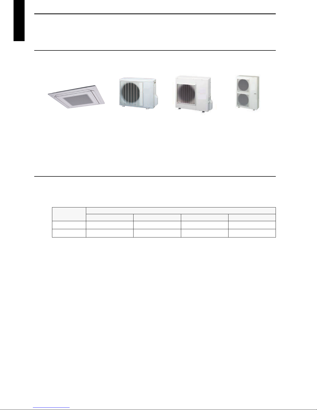
1. Product features
Implemented core technology provides easy-to-use product operations that realize a comfortable
space.
1-1. Model lineup
1-2. Features
Energy efficiency class
Energy saving
• All DC design
• Heat exchange efficiency increased and larger airflow by adoption of new type turbo fan
AUXG18LRLB
AUXG24LRLB
AUXG30LRLB
AUXG36LRLB
AUXG45LRLB
AUXG54LRLB
AOYG18LBCA
AOYG24LBCA
AOYG30LBTA
AOYG36LBTA
AOYG45LBTA
AOYG54LBTA
MODEL
AUXG18LRLB AUXG24LRLB AUXG30LRLB AUXG36LRLB
Cooling
A
++
A
++
A
++
A
++
Heating
A
+
A
+
A
+
A
+
Page 9
- 3 -
CASSETTE TYPE
AUXG18-54LRLB
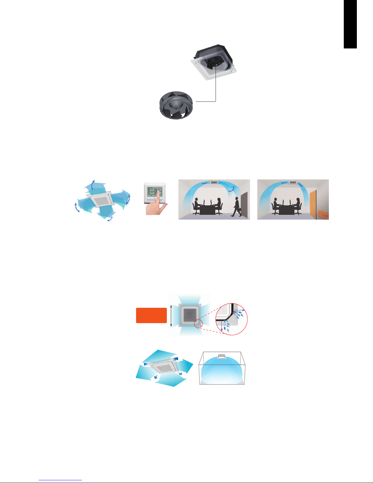
Advancement in comfort
Quiet operation
Individual airflow provides free air conditioning
• Individual airflow can be controlled by wired remote controller.
• Individual airflow also can be controlled in any positions.
Wide airflow achieved quick air conditioning around all direc-
tions
• New wide louver can provide more airflow.
• The louver design distributes airflow at the corner.
• Uniform temperature air conditioning by airflow
Case study:
Comfortable air conditioning
by draft prevention and
swing air blow.
Efficient air conditioning
based on the room layout.
Twist-blade fan
Reduce sound level by decreasing spiral airflow!
* from previous model
22
% up!
About
Comf
ortable!
Page 10
- 4 -
CASSETTE TYPE
AUXG18-54LRLB
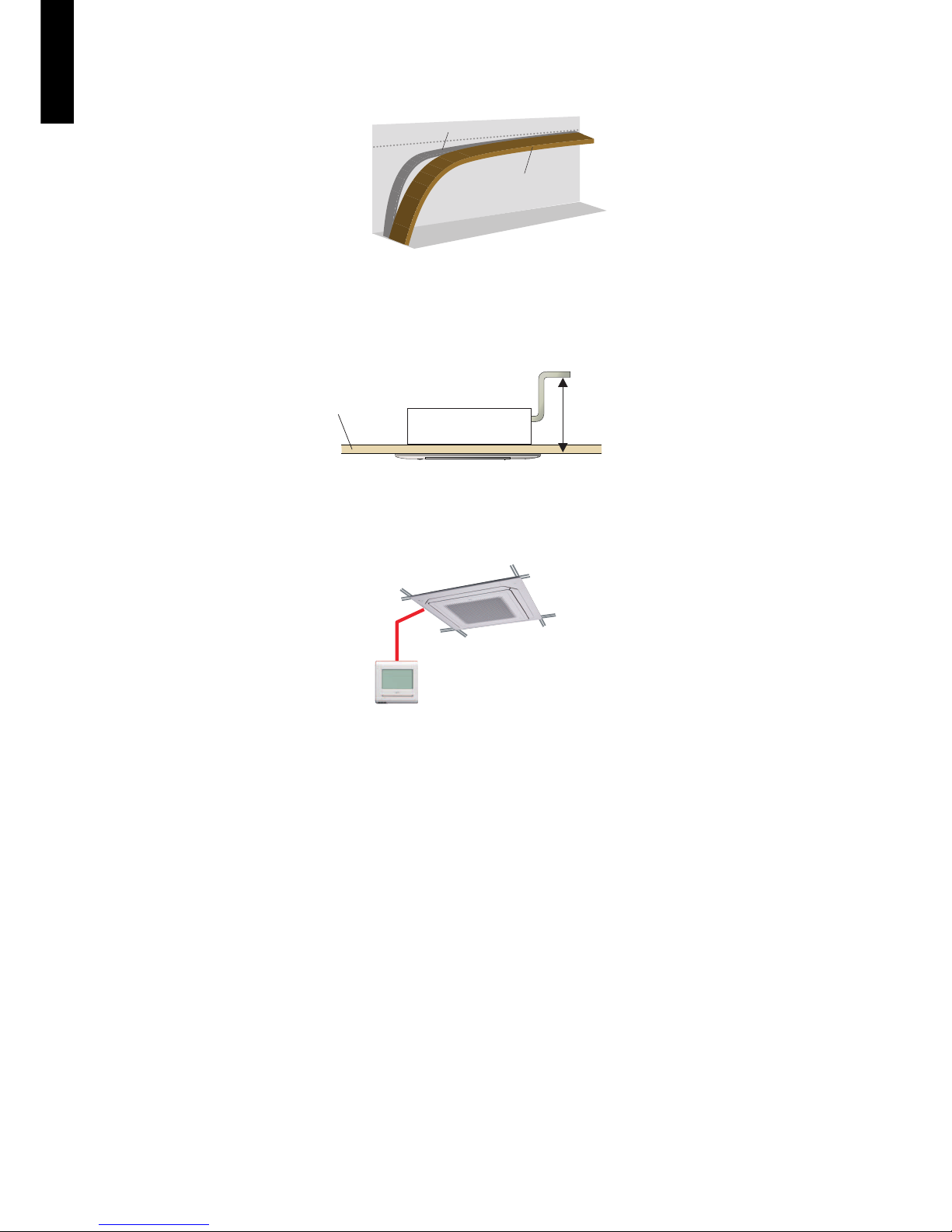
Economy operation
Limits the maximum operation current, and the power consumption is cut down and the maximum load is suppressed.
Improvement of installation and maintenance
High lift drain pump
Easy installation
Easy setting by wired remote controller.
Time
Economy operation
Normal operation
Setting
temperature
850 mm
Ceiling panel
Page 11
- 5 -
CASSETTE TYPE
AUXG18-54LRLB
2. Wired remote controller
2-1. Features
High performance and compact size
In addition to the individual control, various energy saving controls can be realized using 1 remote controller only.
Accurate and comfortable control
Indoor temperature can be detected accurately by the room temperature sensor built in the wired
remote controller.
• Easy finger touch operation with LCD panel
• Built-in weekly/daily timer (on/off, temperature and mode)
• The backlit LCD enables easy operation in a dark room.
• Room temperature display
• Control up to 16 indoor units
• Corresponds to 12 different languages (English, Chinese
French, German, Spanish, Russian, Polish, Italian, Portuguese, Greek, Turkish, and Dutch)
Individual
control
Thermo
sensor
Weekly
timer
Auto off
timer
Room temperature sensor Room temperature display
Page 12
- 6 -
CASSETTE TYPE
AUXG18-54LRLB
Various energy saving control
• Auto-off timer
– The indoor unit automatically turns off after the set time has passed.
– The time interval for which auto-off works can be set.
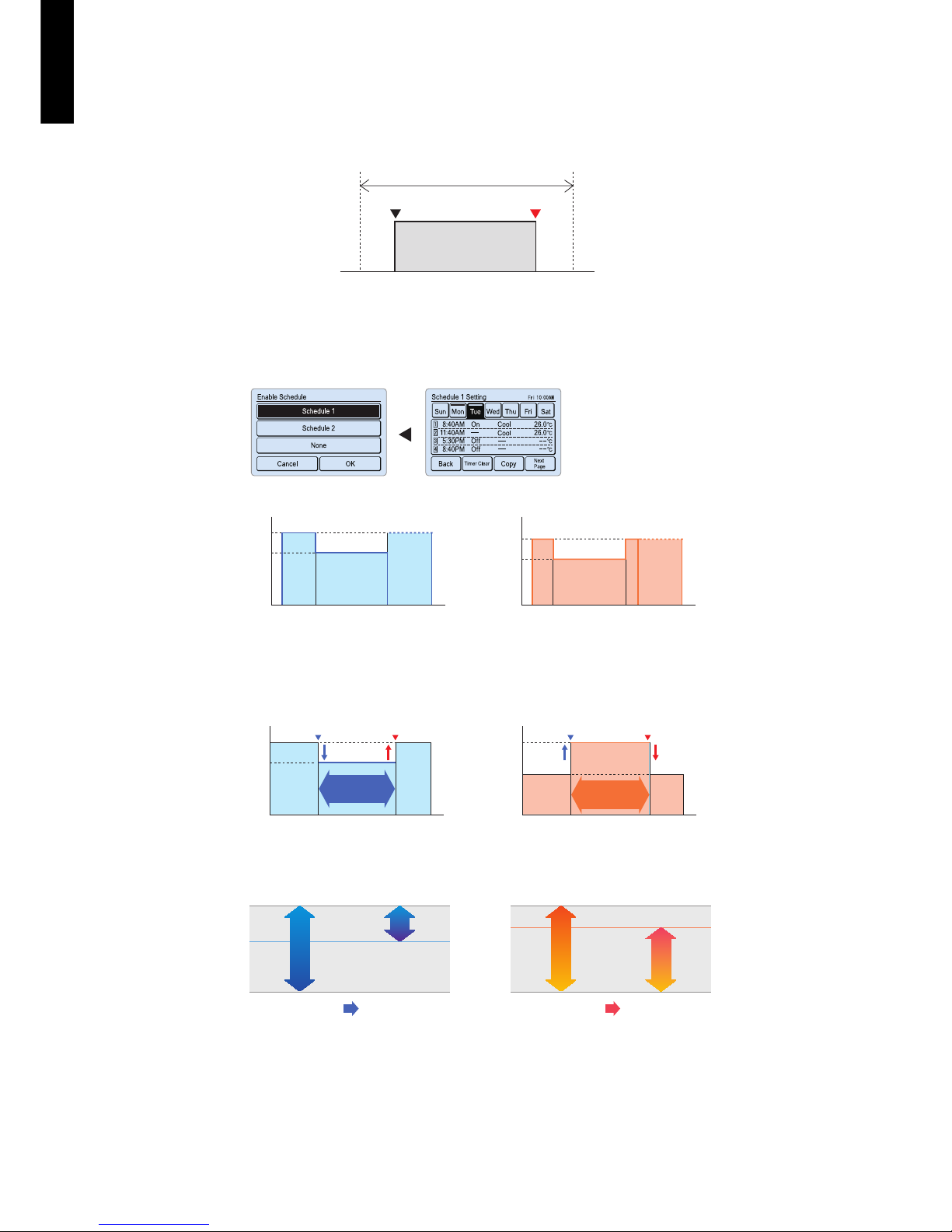
• 2 schedules weekly timer
– 2 schedules such as for the summer and winter can be set.
– 8 setting changeable per day of week (Setting items: on/off, temperature, mode, and time)
• Set temperature auto return
– The setting temperature automatically returns to the previous setting temperature.
– The time range in which the set temperature can be changed is 10 to 120 minutes.
• Set temperature upper and lower limit setting
The set temperature range can be set for each operation mode (COOL, HEAT, and AUTO).
Set interval time hour (17:00 to 24:00)
Set off time
(30 to 240 minutes)
17: 4200 :00
On Auto-off
Off
Example: At interval time hour (17:00 to 24:00) to prevent forgetting to turn off.
Schedule 1 (Summer schedule) Schedule 2 (Winter schedule)
26 °C
24 °C
On
8:40 11:40 17:30 20:40
Off Off Off Off
Time
25 °C
23 °C
On
Setting temp.
Setting temp.
Setting example:
8:40 10:00 17:3015:30 20:40
Time
Setting temp.
Setting temp.
Cooling operation
24 °C
22 °C
Set temperature change Auto return
11:40 13:40
Time
Settable time range
10 to 120 minutes
Heating operation
25 °C
23 °C
Set temperature change Auto return
11:40 13:40
Time
Settable time range
10 to 120 minutes
Original temp.
setting range
Lower limit
setting
During cooling
30 °C
25 °C
18 °C
Original temp.
setting range
Upper limit
setting
During heating
30 °C
25 °C
16 °C
Page 13
- 7 -
CASSETTE TYPE
AUXG18-54LRLB
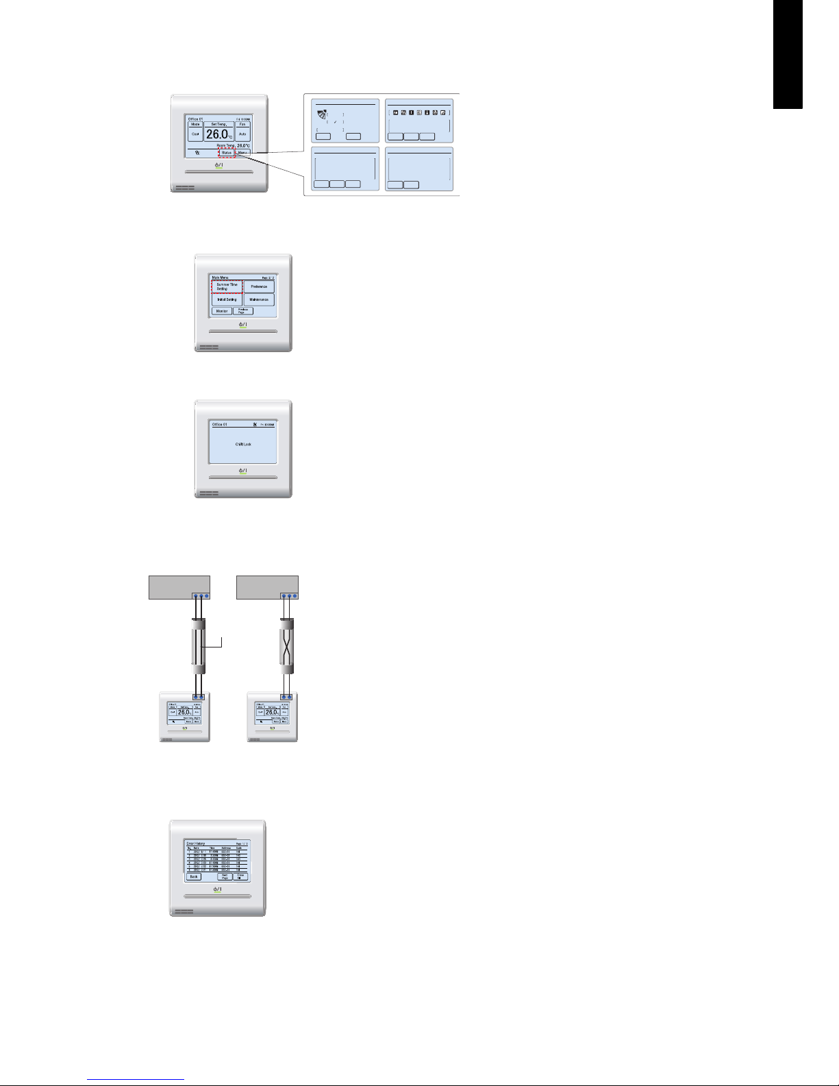
Various convenient functions
• Displays setting status and limitations
• Summer time display
• Child safety lock
Simplified installation
Easy maintenance
The remote controller settings can be easily
checked.
Can be set easily from “Menu” screen.
Lock/unlock procedure: While touching the blank field on “Monitor”
screen, push the on/off button for 4 seconds.
Use of non-polar 2-wire type
Faulty wiring can be prevented by using non-polar 2-wire.
Error history display
• Errors occur on the indoor unit or the remote controller are saved as
a history.
• Maximum of 32-error incidents can be saved.
• Under Maintenance
• Forced Stop
• Mode Mismatch
Previous
Page
Status
R.C. Prohibition
Special State
Page 2/ 4
Monitor
Next
Page
• Op. Controlled
• Set Temp. Limited
• Energy Saving Operation
• Defrost
• Oil Recovery
Status
Special Srate
Page 3/ 4
Monitor
Previous
Page
Next
Page
• Human Sensor Setting
• Fan Control for Energy Saving
Status
Special Srate
Page 4/ 4
Monitor
Previous
Page
Status
Air Flow Direction
VT
Off
1
Economy
Individual
Page 1/ 4
Monitor
Next
Page
OK OK
non-polar
2-wire
Y1
Y2
Y1
Y2
I.U. I.U.
Y1Y2Y3 Y1Y2Y3
Page 14
- 8 -
CASSETTE TYPE
AUXG18-54LRLB
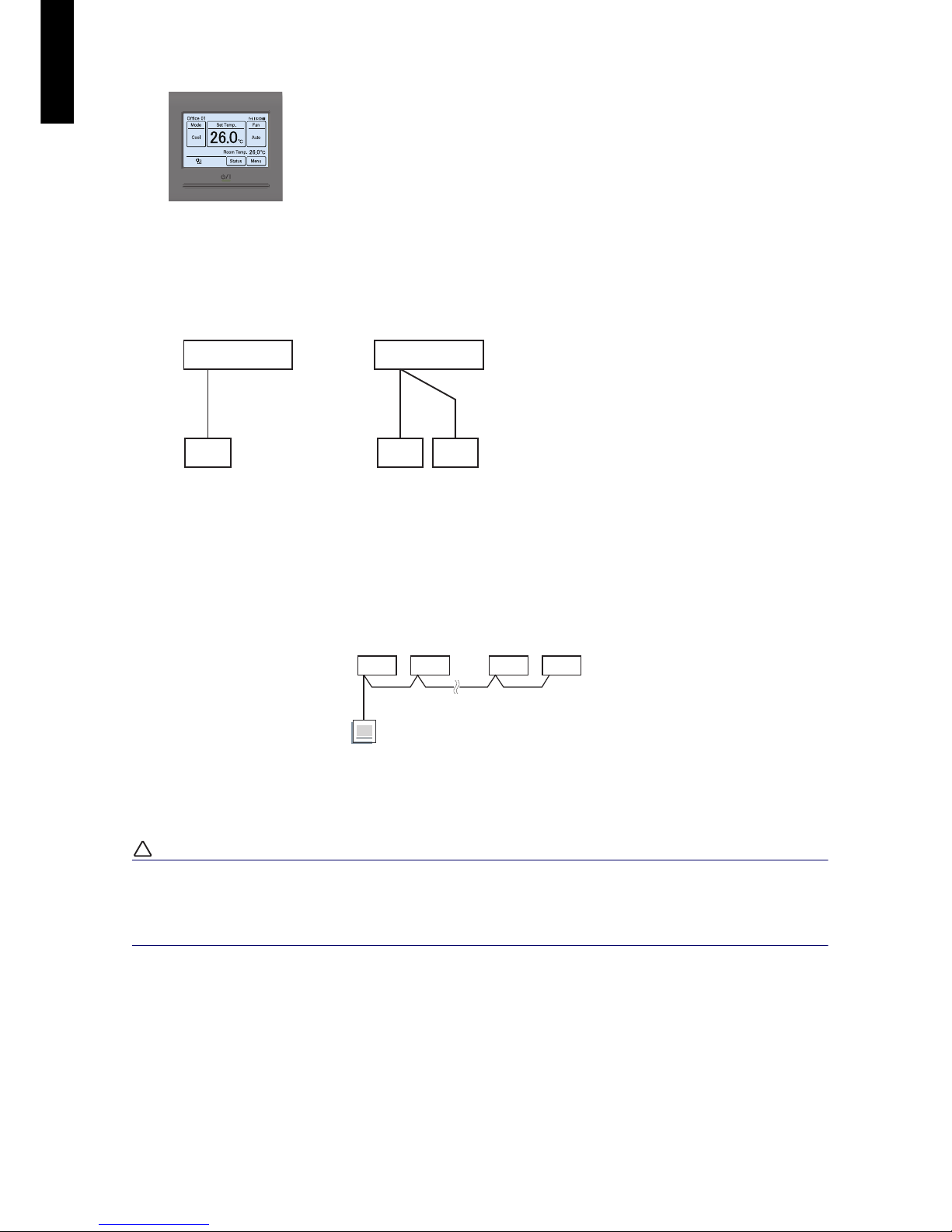
Backlit LCD
System diagram
NOTE: Multiple installation method described above is prohibited to combine with 2-wired type
and 3-wired type.
Group control
With a single remote controller, up to 16 units can be simultaneously operated.
A, B, C, D, E : Remote controller cable. (Refer to Chapter 2-4. "Wiring specifications" on page
10.)
A+B+C+D+E ≤ 500 m.
!
CAUTION
Group control is only possible between units with remote controllers of the same type.
After confirming that the connected remote controllers have same model name by checking
the rear side of the remote controller or “Chapter 13-1. "Controllers" on page 77”, perform
the group control.
• The backlit LCD enables easy operation in a dark room.
• Backlighting time can be selected from 30 or 60 seconds.
• The backlight is lit while the buttons are operated, and goes off 30 or
60 seconds after the operation stops.
1 remote controller 2 remote controllers
A, B, C: Remote controller cable
A≤ 500 m; B+C≤ 500 m
A
Indoor unit
Remote controller
Master
Slave
BC
Indoor unit
Remote controllers
A
BCDE
I.U. I.U. I.U. I.U.
Master
I.U.: Indoor Unit
Page 15
- 9 -
CASSETTE TYPE
AUXG18-54LRLB
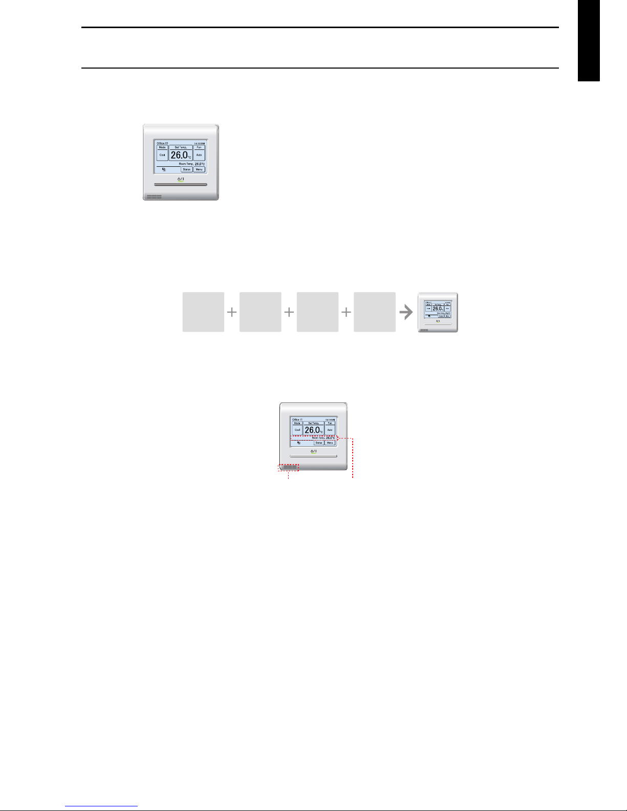
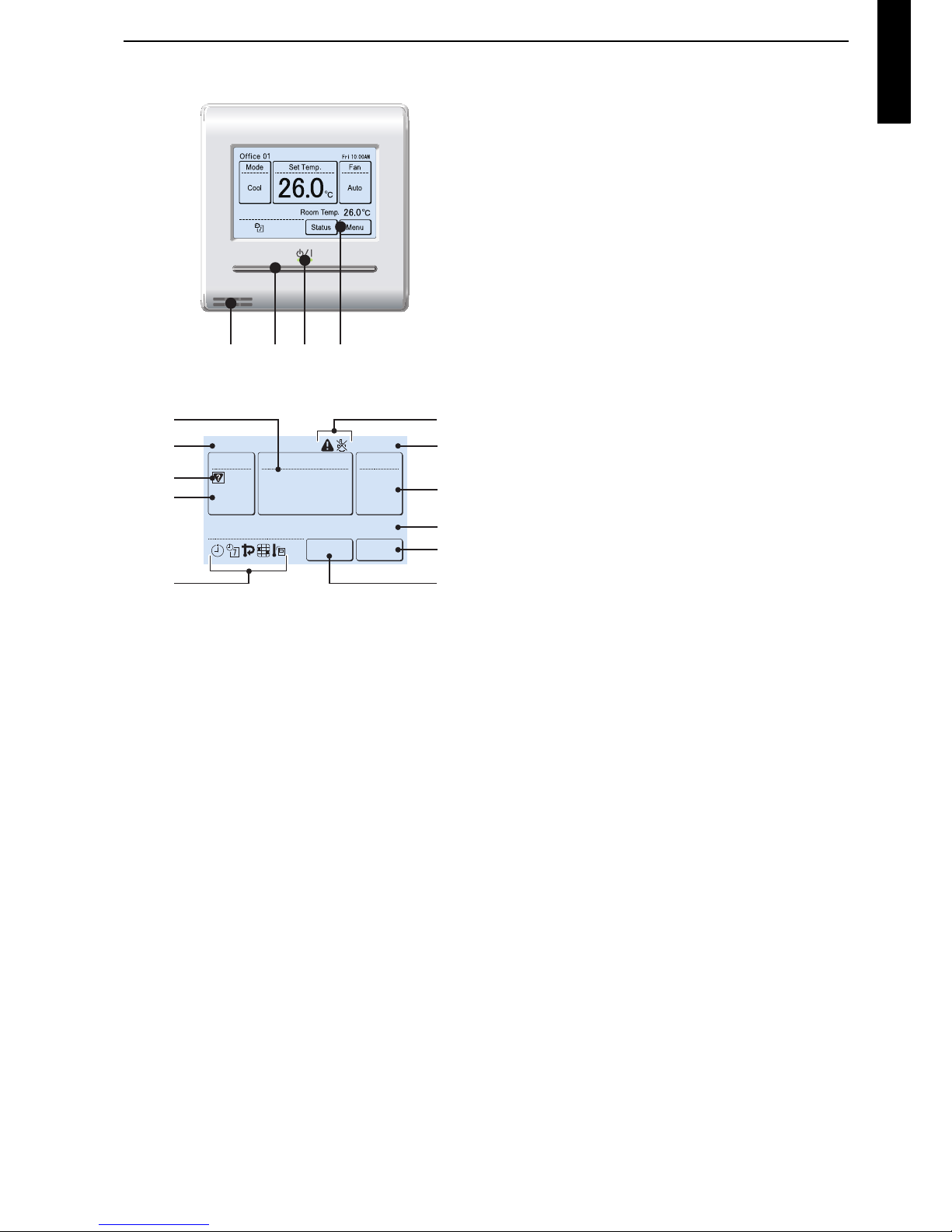
2-2. Overview
Display panel
a Remote temperature sensor (inside)
b On/off button
Operable only while displaying the “Monitor mode”
screen.
c LED lamp (operation indicator)
d Touch panel display
e Set temperature
Operating temperature can be set.
f Remote controller group name
g Mode
Operation mode can be set.
h Status icons
i Clock
j Fan
Fan speed can be set.
k Room temperature
l Menu
Various settings can be set.
m Status
Status of the indoor unit and error can be checked.
NOTE: Functions may differ by type of the indoor unit.
For details, refer to the operation manual.
abcd
26.0
26.0
°C
°C
Cool
Auto
Office 01
Set Temp.
26.0°C
26.0°C
Mode
MenuStatus
Fan
Fri 10:00AM
Room Temp.
e
f
h
h
g
h
i
j
l
m
k
Page 16
- 10 -
CASSETTE TYPE
AUXG18-54LRLB
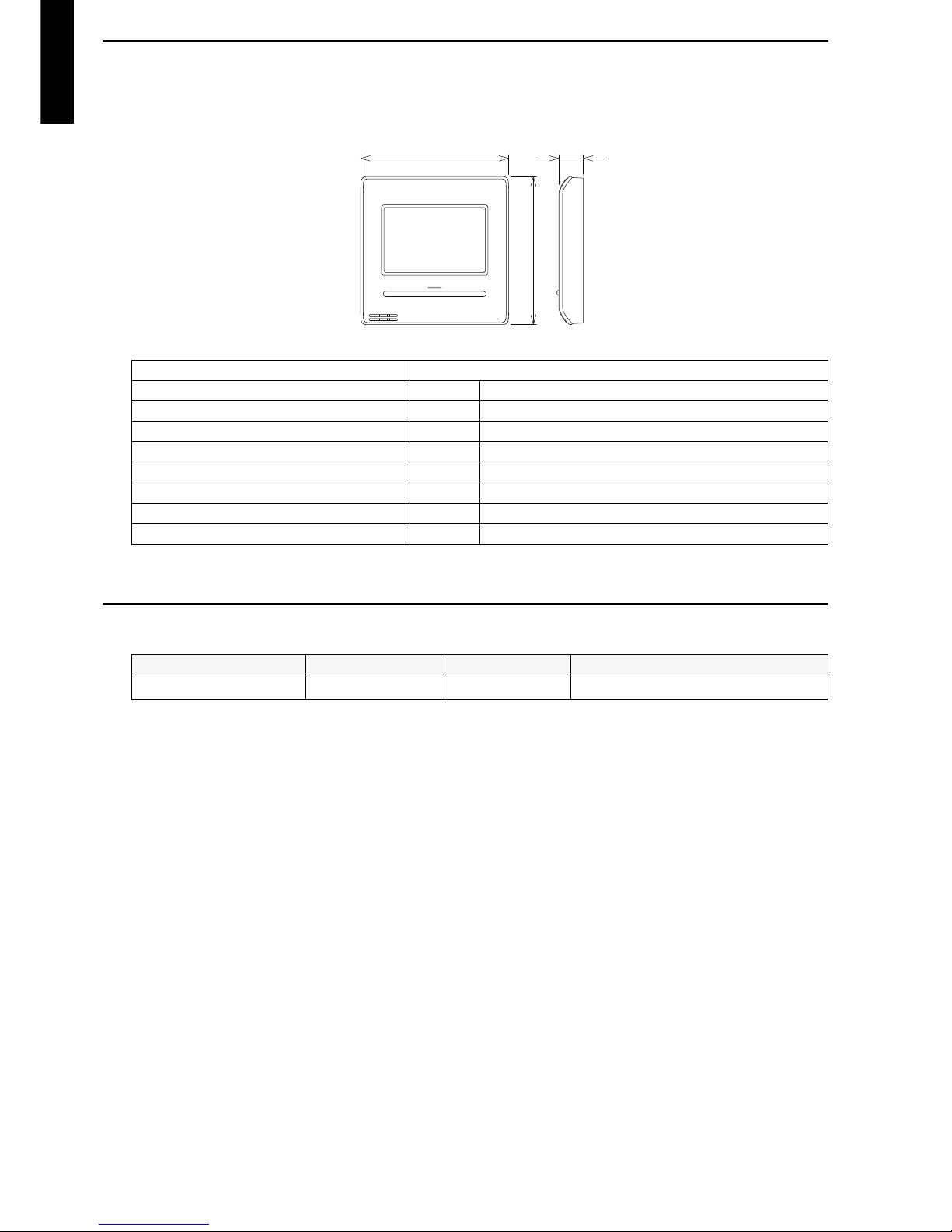
2-3. Specifications
Dimensions and other specifications on the wired remote controller are as follows.
2-4. Wiring specifications
NOTE: Use shielded cable (locally purchased) in accordance with the regional cable standard.
Display 3.8-inch FSTN LCD (255 × 160 dots) with touch panel
Dimensions (H × W × D) mm 120 × 120 × 20.4
Weight g 220
Input voltage V DC 12
Power consumption W Max. 0.3
Usage temperature range °C 0 to 40
Usage humidity range % 20 to 90 (no condensation)
Storage temperature range °C -10 to 60
Storage humidity range % 20 to 90 (no condensation)
Use Cable size Wire type Remarks
Remote controller cable
0.33 to 1.25 mm
2
Non-polar 2-core Use sheathed PVC cable.
20.4120
120
[Unit:mm]
Page 17
- 11 -
CASSETTE TYPE
AUXG18-54LRLB
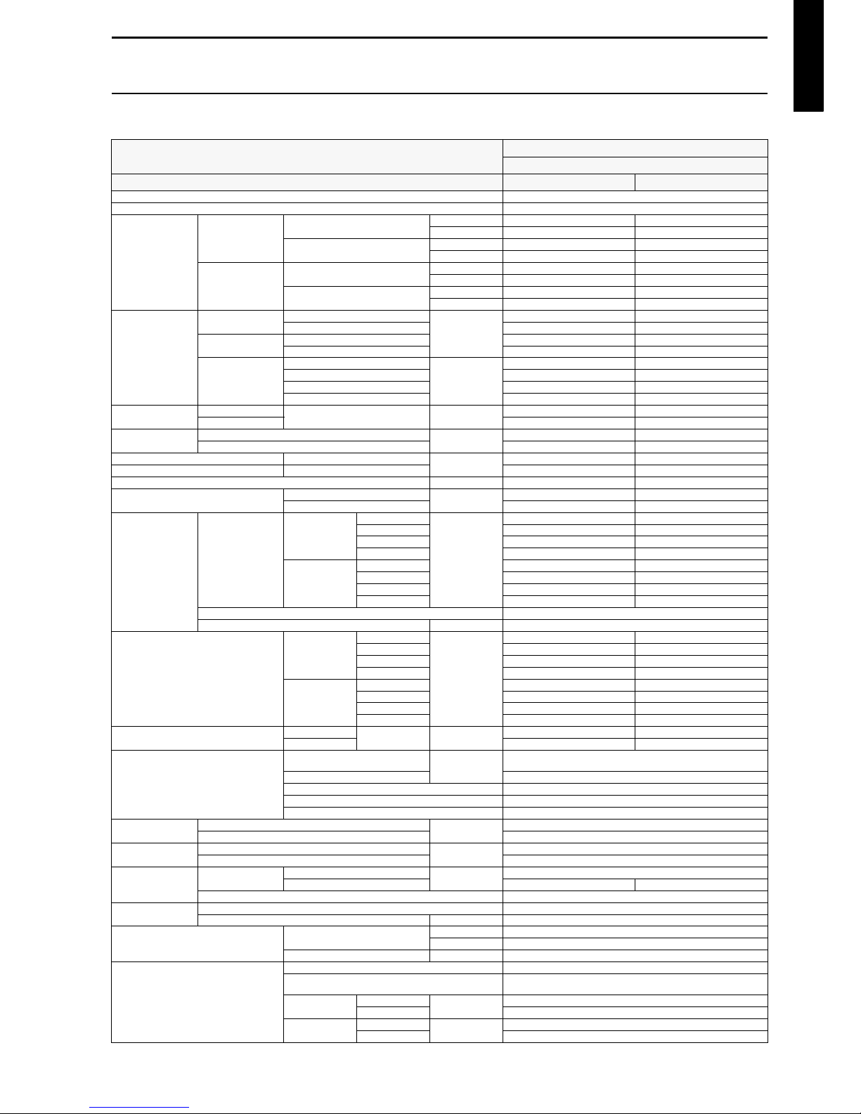
3. Specifications
3-1. Models: AUXG18LRLB and AUXG24LRLB
Typ e
Cassette
Inverter heat pump
Model name AUXG18LRLB AUXG24LRLB
Power supply 230 V ~ 50 Hz
Available voltage range 198—264 V
Capacity
Cooling
Rated
kW 5.2 6.8
Btu/h 17,700 23,200
Min.—Max.
kW 0.90—6.50 0.90—8.00
Btu/h 3,100—22,200 3,100—27,300
Heating
Rated
kW 6.0 7.8
Btu/h 20,500 26,600
Min.—Max.
kW 0.90—8.00 0.90—9.10
Btu/h 3,100—27,300 3,100—31,000
Input power
Cooling
Rated
kW
1.42 2,16
Max. 2.28 3.08
Heating
Rated 1.50 2.18
Max. 3.08 4.22
Fan
HIGH
W
16 21
MED 12 16
LOW 11 13
QUIET 79
Current
Cooling
Rated A
6.2 9.5
Heating 6.6 9.6
Power factor
Cooling
%
99.6 98.9
Heating 98.8 98.7
EER Cooling
kW/kW
3.66 3.15
COP Heating 4.00 3.58
Moisture removal L/h (pints/h) 2.2 (3.9) 2.7 (4.8)
Maximum operating current *1
Cooling
A
10.0 13.5
Heating 13.5 18.5
Fan
Airflow rate
Cooling
HIGH
m3/h
1,050 1,150
MED 960 1,050
LOW 900 980
QUIET 780 870
Heating
HIGH 1,050 1,150
MED 960 1,050
LOW 900 980
QUIET 780 870
Type × Q'ty Turbo fan × 1
Motor output W 81
Sound pressure level *2
Cooling
HIGH
dB (A)
33 35
MED 32 33
LOW 31 32
QUIET 28 29
Heating
HIGH 33 35
MED 32 33
LOW 31 32
QUIET 28 29
Sound power level
Cooling
HIGH dB (A)
47 49
Heating 47 49
Heat exchanger type
Dimensions (H × W × D)
mm
210 × 2,127 × 13.3
210 × 2,061 × 13.3
Fin pitch 1.2
Rows × Stages 2 × 10
Pipe type Copper tube
Fin type Aluminum
Dimensions
(H × W × D)
Net
mm
246 × 840 × 840
Gross 298 × 960 × 950
Weight
Net
kg
24
Gross 29
Connection pipe
Size
Liquid
mm (in)
Ø 6.35 (Ø 1/4)
Gas Ø 12.70 (Ø 1/2) Ø 15.88 (Ø 5/8)
Method Flare
Drain hose
Material PVC(VP25)
Size mm Ø 25 (I.D.), Ø 32 (O.D .)
Operation range
Cooling
°C 18 to 32
%RH 80 or less
Heating °C 16 to 30
Cassette grille
Material PS
Color
White
Approximate color of MUNSELL N 9.25/
Dimensions
(H × W × D)
Net
mm
53 × 950 × 950
Gross 110 × 1,000 × 1,010
Weight
Net
kg
6.0
Gross 10.5
Page 18

- 12 -
CASSETTE TYPE
AUXG18-54LRLB
Remote controller type Wired (Wireless [option])
NOTES:
Specifications are based on the following conditions:
–Cooling: Indoor temperature of 27 °CDB/19 °CWB, and outdoor temperature of 35 °CDB/24 °CWB.
–Heating: Indoor temperature of 20 °CDB/15 °CWB, and outdoor temperature of 7 °CDB/6 °CWB.
–Pipe length: 5 m, Height difference: 0 m. (Between outdoor unit and indoor unit.)
Protective function might work when using it outside the operation range.
*1: Maximum current:
–The maximum value when operated within the operation range.
–The total current of indoor unit and outdoor unit.
*2: Sound pressure level:
–Measured values in manufacturer’s anechoic chamber.
–Because of the surrounding sound environment, the sound levels measured in actual installation conditions might be higher than the specified values here.
Model name AUXG18LRLB AUXG24LRLB
Energy efficiency class
Cooling
A
++
A
++
Heating (Average)
A
+
A
+
Pdesign
Cooling
kW
5.2 (35°C) 6.8 (35°C)
Heating (Average) 4.3 (-10°C) 6.0 (-10°C)
SEER Cooling
kWh/kWh
7.05 6.60
SCOP Heating ( Average) 4.40 4.20
Annual energy consumption
QCE
kWh/a
258 361
QHE (Average) 1,367 1,999
Sound power level
Cooling
HIGH dB (A)
47 49
Heating 47 49
Typ e
Cassette
Inverter heat pump
Model name AUXG18LRLB AUXG24LRLB
Page 19
- 13 -
CASSETTE TYPE
AUXG18-54LRLB
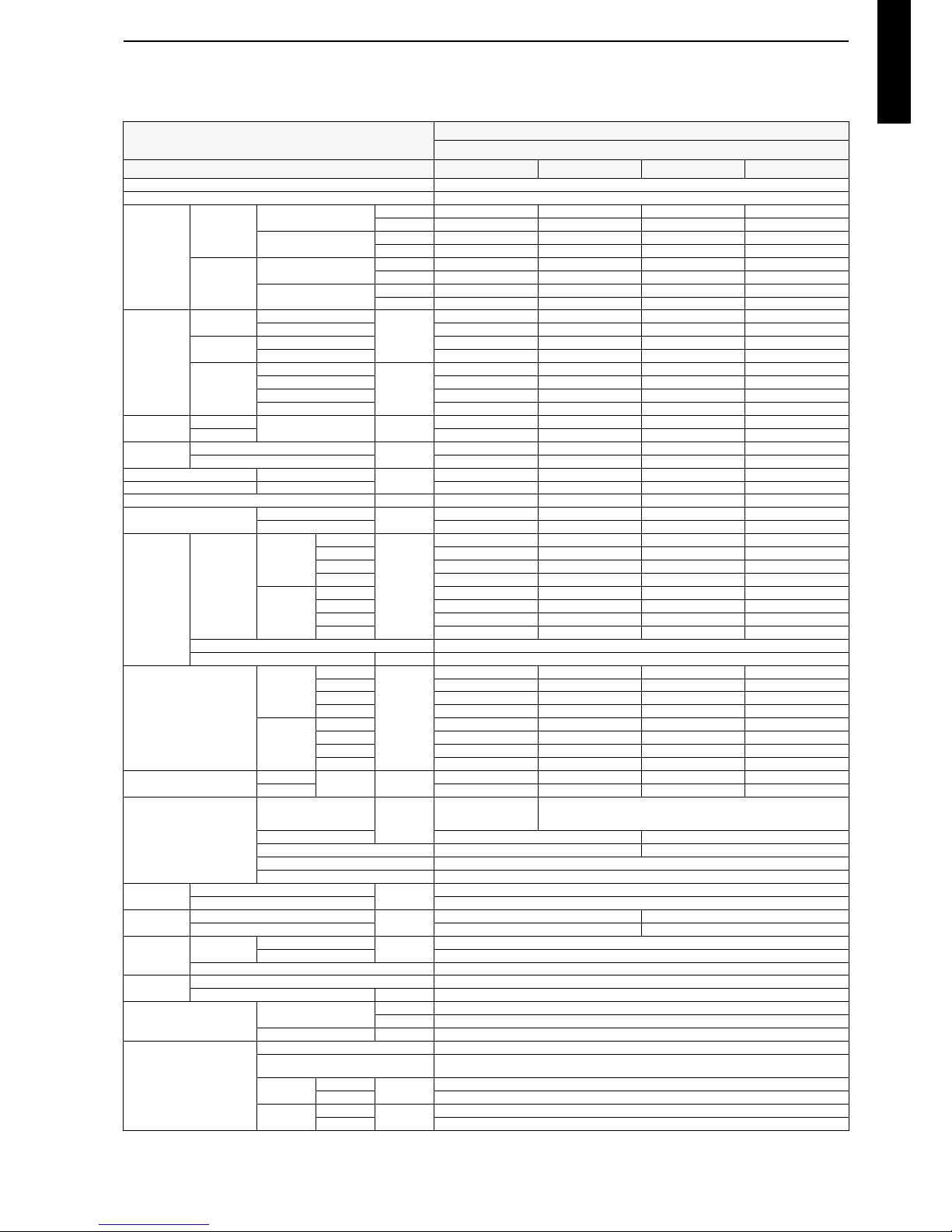
3-2. Models: AUXG30LRLB, AUXG36LRLB, AUXG45LRLB, and
AUXG54LRLB
Typ e
Cassette
Inverter heat pump
Model name AUXG30LRLB AUXG36LRLB AUXG45LRLB AUXG54LRLB
Power supply 230 V ~ 50 Hz
Available voltage range 198—264 V
Capacity
Cooling
Rated
kW 8.5 9.5 12.5 13.3
Btu/h 29,000 32,400 42,700 45,400
Min.—Max.
kW 2.8—10.0 2.8—11.2 4.0—14.0 4.5—14.5
Btu/h 9,500—34,100 9,500—38,200 13,700—47,800 21,200—49,500
Heating
Rated
kW 10 .0 10.8 14. 0 15.8
Btu/h 34,100 36,900 47,800 53,900
Min.—Max.
kW 2.70—11.20 2.7—12.7 4.2—16.2 4.7—16.5
Btu/h 9,200—38,200 9,200—43,300 14,300—55,300 16,000—56,300
Input power
Cooling
Rated
kW
2.56 2. 96 3.85 4.3 8
Max. 3.88 4.56 4.70 4.94
Heating
Rated 2.77 2.91 3.73 4.58
Max. 3.88 4.56 4.70 4.94
Fan
HIGH
W
52 87 106 129
MED 39526095
LOW 31394555
QUIET 20233034
Current
Cooling
Rated A
11.2 13.0 16.8 19.1
Heating 12.212.716.320.0
Power factor
Cooling
%
99.4 99 .0 99.6 99 .2
Heating 98.799.699.599.6
EER Cooling
kW/kW
3.32 3. 21 3.25 3.0 4
COP Heating 3.61 3.71 3.75 3.45
Moisture removal L/h (pints/h) 2.5 (4.4) 3.3 (5.8) 4.5 (7.9) 5.0 (8.8)
Maximum operating current *1
Cooling
A
17.0 20 .0 20.5 21 .5
Heating 17.0 20.0 20.5 21.5
Fan
Airflow rate
Cooling
HIGH
m3/h
1,600 1,900 2,000 2,100
MED 1,400 1,590 1,650 1,780
LOW 1,270 1,420 1,460 1,600
QUIET 1,150 1,180 1,300 1,320
Heating
HIGH 1,600 1,900 2,000 2,100
MED 1,400 1,590 1,650 1,780
LOW 1,270 1,420 1,460 1,600
QUIET 1,150 1,180 1,300 1,320
Type × Q'ty Turbo fan × 1
Motor output W 81
Sound pressure level *2
Cooling
HIGH
dB (A)
40 44 46 47
MED 38414243
LOW 36383940
QUIET 33343536
Heating
HIGH 40 44 46 47
MED 38414243
LOW 36383940
QUIET 33343536
Sound power level
Cooling
HIGH dB (A)
54 58 60 61
Heating 54586061
Heat exchanger type
Dimensions (H × W × D)
mm
252 × 2,124 × 13.3
252 × 2,062 × 13.3
252 × 2,124 × 13.3
252 × 2,062 × 13.3
252 × 1,999 × 13.3
Fin pitch 1.2 1.3
Rows × Stages 2 × 12 3 × 12
Pipe type Copper tube
Fin type Aluminum
Dimensions
(H × W × D)
Net
mm
288 × 840 × 840
Gross 350 × 960 × 950
Weight
Net
kg
26 29
Gross 32 34
Connection
pipe
Size
Liquid
mm (in)
Ø 9.52 (Ø 3/8)
Gas Ø 15.88 (Ø 5/8)
Method Brazing
Drain hose
Material PVC(VP25)
Size mm Ø 25 (I.D.), Ø 32 (O.D.)
Operation range
Cooling
°C 18 to 32
%RH 80 or less
Heating °C 16 to 30
Cassette grille
Material PS
Color
White
Approximate color of MUNSELL N 9.25/
Dimensions
(H × W × D)
Net
mm
53 × 950 × 950
Gross 110 × 1,000 × 1,010
Weight
Net
kg
6.0
Gross 10.5
Page 20
- 14 -
CASSETTE TYPE
AUXG18-54LRLB
Remote controller type Wired (Wireless [option])
NOTES:
Specifications are based on the following conditions:
–Cooling: Indoor temperature of 27 °CDB/19 °CWB, and outdoor temperature of 35 °CDB/24 °CWB.
–Heating: Indoor temperature of 20 °CDB/15 °CWB, and outdoor temperature of 7 °CDB/6 °CWB.
–Pipe length: 5 m, Height difference: 0 m. (Between outdoor unit and indoor unit.)
Protective function might work when using it outside the operation range.
*1: Maximum current:
–The maximum value when operated within the operation range.
–The total current of indoor unit and outdoor unit.
*2: Sound pressure level:
–Measured values in manufacturer’s anechoic chamber.
–Because of the surrounding sound environment, the sound levels measured in actual installation conditions might be higher than the specified values here.
Model name AUXG30LRLB AUXG36LRLB
Energy efficiency class
Cooling
A
++
A
++
Heating (Average)
A
+
A
+
Pdesign
Cooling
kW
8.5 (35°C) 9.5 (35°C)
Heating (Average) 8.0 (-10°C) 8.7 (-10°C)
SEER Cooling
kWh/kWh
6.70 6.40
SCOP Heating ( Average) 4.30 4.30
Annual energy consumption
QCE
kWh/a
444 519
QHE (Average) 2,604 2,833
Sound power level
Cooling
HIGH dB (A)
54 58
Heating 54 58
Typ e
Cassette
Inverter heat pump
Model name AUXG30LRLB AUXG36LRLB AUXG45LRLB AUXG54LRLB
Page 21
- 15 -
CASSETTE TYPE
AUXG18-54LRLB
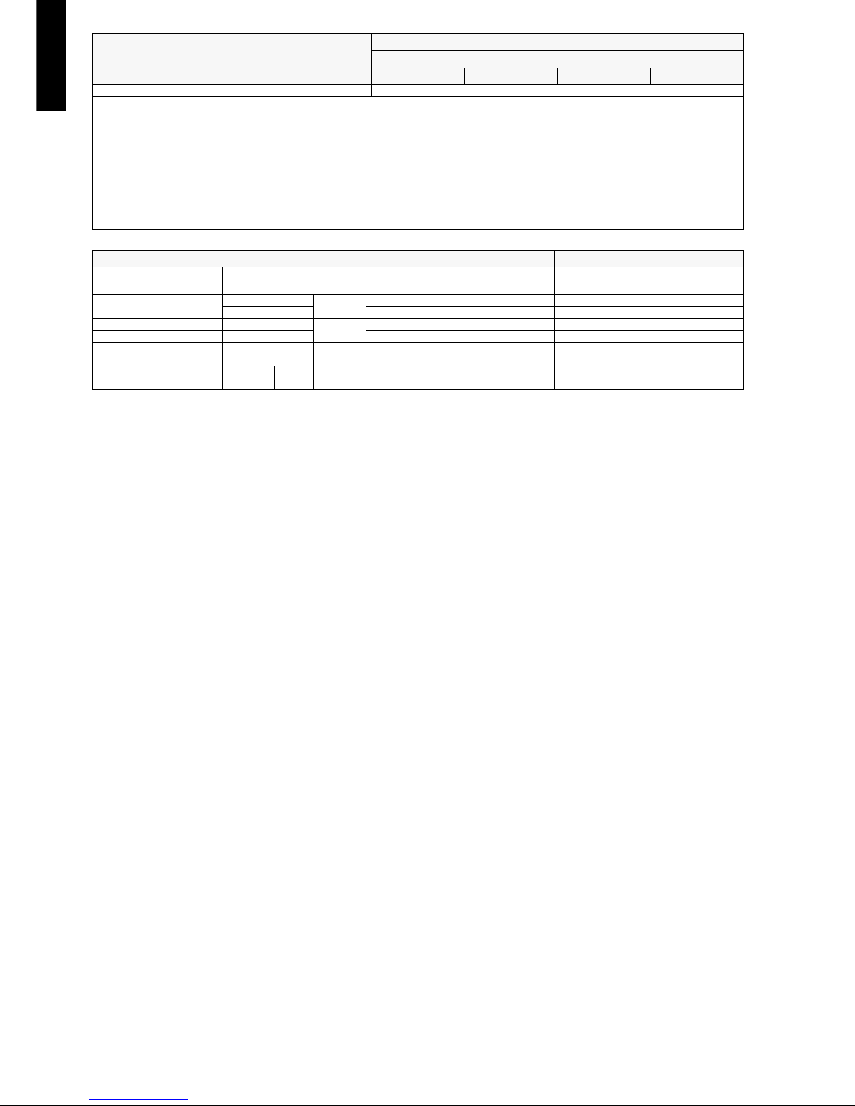
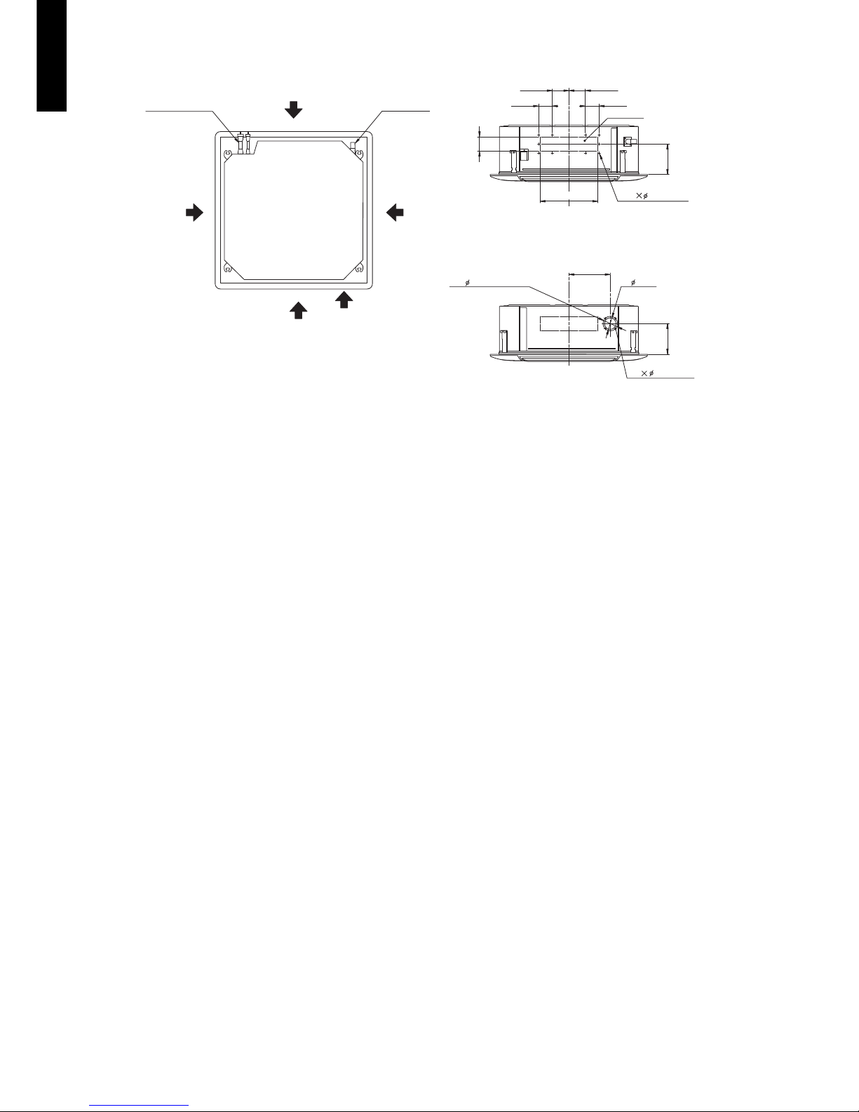
4. Dimensions
4-1. Models: AUXG18LRLB and AUXG24LRLB
Ceiling opening and hanging bolt pitch
Refrigerant piping and drain piping positions
246
256
40
10
140–145
50–100
950 (Panel frame)
20–45 20–45
50
80
130
130
130
200
840 (Body frame)
796 (Hanging bolt pitch)
768 (Hanging bolt pitch)
860–910 (Ceiling opening)
950 (Panel frame)
840 (Body frame)
860–910 (Ceiling opening)
20–4520–45
Unit: mm
45
293342
140
180
200
Drain pipe
(Connect the attached drain hose)
Unit: mm
Page 22
- 16 -
CASSETTE TYPE
AUXG18-54LRLB
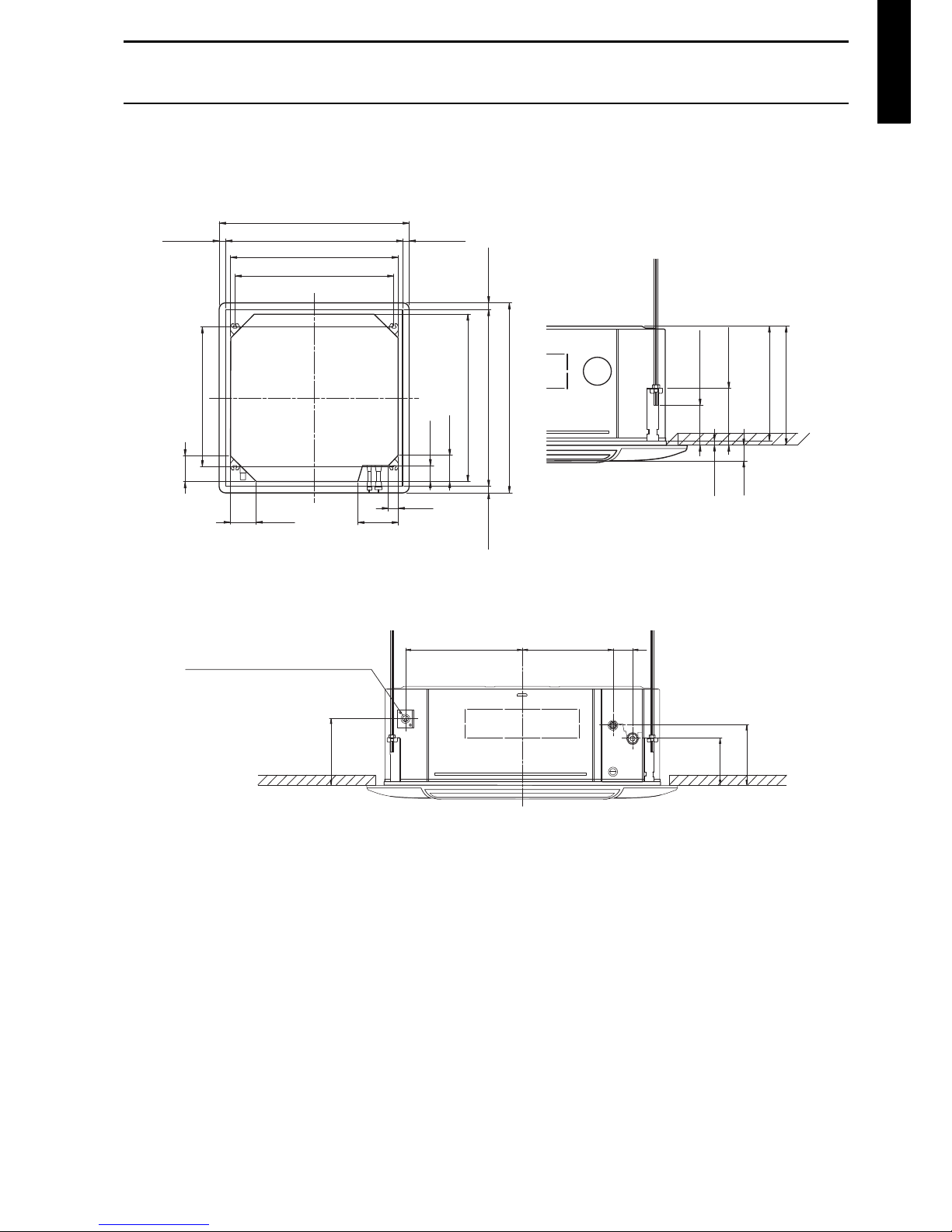
Airflow split-flow duct and fresh-air inlet positions
114
95
3.2 hole
3.2 hole
280
352
100
83
83
90
100
163
163
Airflow split-flow duct connecting port
Airflow split-flow duct connecting port
Airflow split-flow duct connecting port
Fresh air inlet position
Fresh air inlet position
Drain pipe
Refrigerant pipe
Detailed diagram of branched duct connecting port
(4 sides)
Knockout hole pitch
Cut out
Cut out
Airflow split-flow duct connecting port
10
4
Unit: mm
Page 23
- 17 -
CASSETTE TYPE
AUXG18-54LRLB
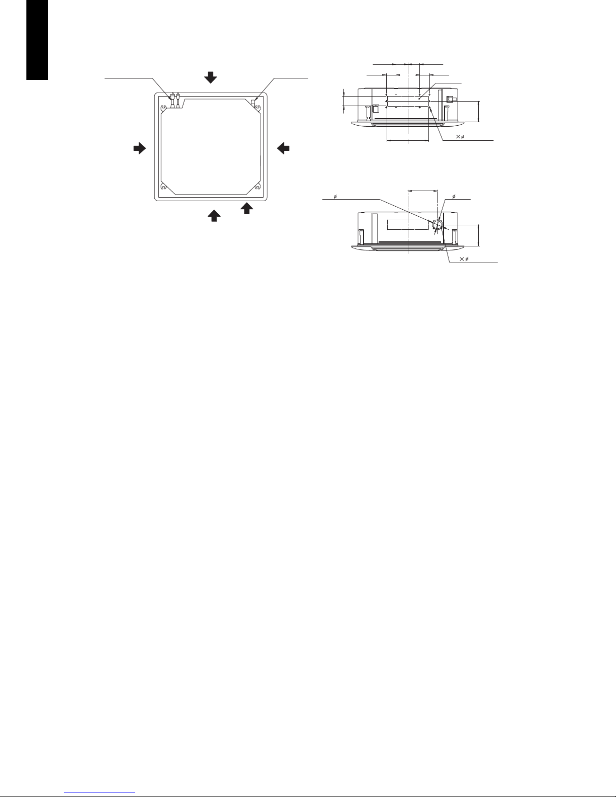
4-2. Models: AUXG30LRLB, AUXG36LRLB, AUXG45LRLB, and
AUXG54LRLB
Ceiling opening and hanging bolt pitch
Refrigerant piping and drain piping positions
288
298
40
10
200–205
50–100
950 (Panel frame)
20–45 20–45
50
80
130
130
130
200
840 (Body frame)
796 (Hanging bolt pitch)
768 (Hanging bolt pitch)
860–910 (Ceiling opening)
950 (Panel frame)
840 (Body frame)
860–910 (Ceiling opening)
20–4520–45
Unit: mm
45
293342
140
180
200
Drain pipe
(Connect the attached drain hose)
Unit: mm
Page 24
- 18 -
CASSETTE TYPE
AUXG18-54LRLB
Airflow split-flow duct and fresh-air inlet positions
114
95
3.2 hole
3.2 hole
280
352
100
83
83
90
100
163
163
Airflow split-flow duct connecting port
Airflow split-flow duct connecting port
Airflow split-flow duct connecting port
Fresh air inlet position
Fresh air inlet position
Drain pipe
Refrigerant pipe
Detailed diagram of branched duct connecting port
(4 sides)
Knockout hole pitch
Cut out
Cut out
Airflow split-flow duct connecting port
10
4
Unit: mm
Page 25
- 19 -
CASSETTE TYPE
AUXG18-54LRLB
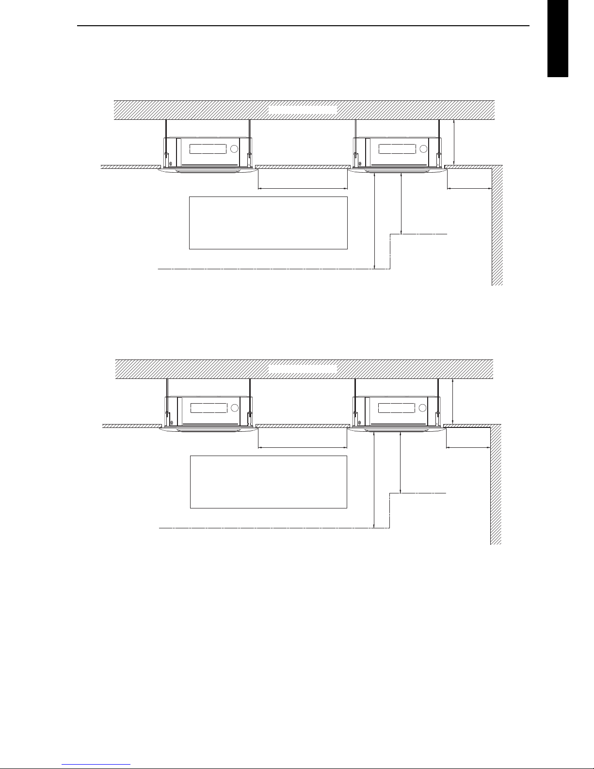
4-3. Installation space requirement
Provide sufficient installation space for product safety.
For 4-direction setting (AUXG18LRLB and AUXG24LRLB):
*: For the details of position adjustment by ceiling mode, refer to “Contents of function setting” on
page 69.
For 4-direction setting (AUXG30LRLB, AUXG36LRLB, AUXG45LRLB, and AUXG54LRLB):
*: For the details of position adjustment by ceiling mode, refer to “Contents of function setting” on
page 69.
1,500
or more
1,000 or more
1,800 or more
Obstruction
3,000 or more
Strong and durable ceiling
Floor
Ceiling height
Ceiling mode* “Low” : 2.7 m
Ceiling mode “Standard” : 3.0 m
Ceiling mode “High” : 3.5 m
256 or more
Unit: mm
1,500
or more
1,000 or more
1,800 or more
Obstruction
3,000 or more
Strong and durable ceiling
Floor
Ceiling height
Ceiling mode* “Low” : 2.7 m
Ceiling mode “Standard” : 3.2 m
Ceiling mode “High” : 4.2 m
298 or more
Unit: mm
Page 26
- 20 -
CASSETTE TYPE
AUXG18-54LRLB
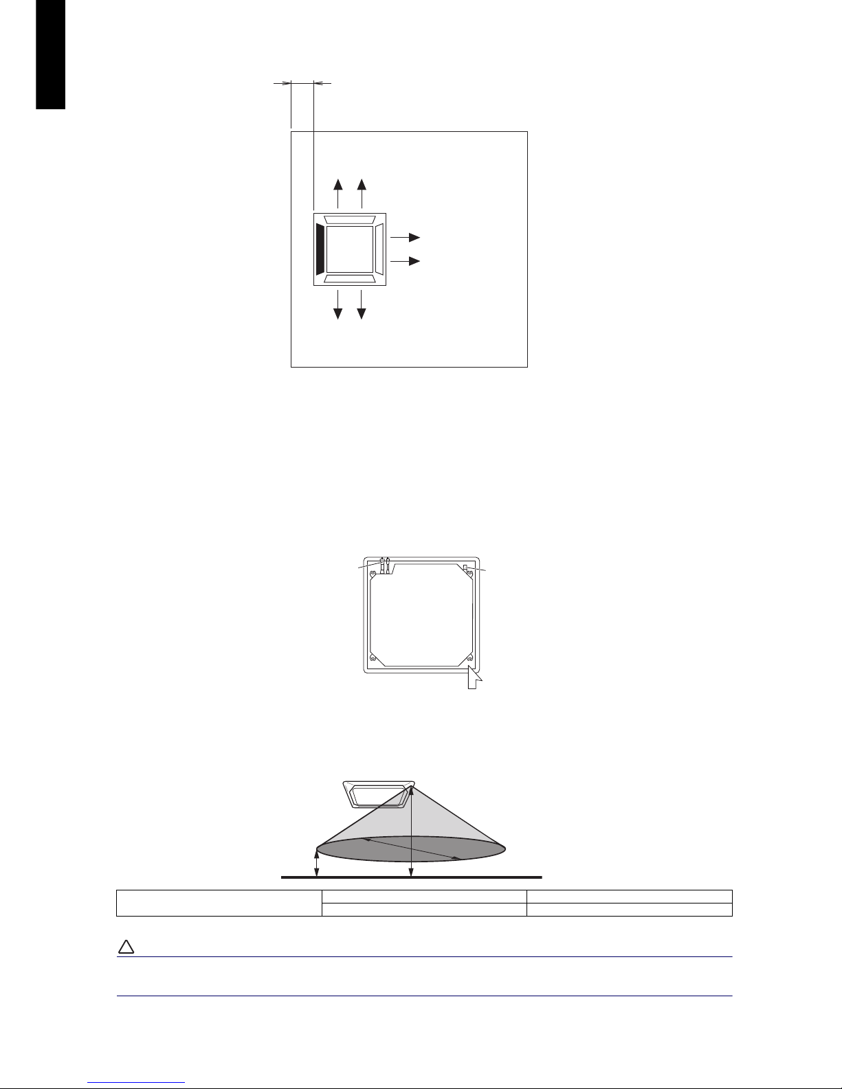
For 3-direction setting:
NOTES:
• To set “3-direction”, optional Air outlet shutter plate (UTR-YDZK) must be installed, and the
“outlet-direction” need to be switched to “3-way” by remote controller.
• The ceiling height cannot be set in the 3-way outlet mode. Therefore, ceiling height setting change
by function setting 20 is prohibited. For details, refer to “Contents of function setting” on page 69.
Human sensor(Option)
Example of sensitivity range:
When the installation height gets higher, the temperature sensitivity decreases.
!
CAUTION
Do not place large objects near the human sensor. Also keep heating units outside the sensor’s
detection area.
Equal sensitivity range of temperature
Ceiling height 3,200 mm
Detecting position 800 mm from floor surface
100 or more
Unit: mm
Drain
pipe
Refrigerant
pipe
Human
sensor
Top view
3,200
800
8,800
Unit: mm
Page 27
- 21 -
CASSETTE TYPE
AUXG18-54LRLB
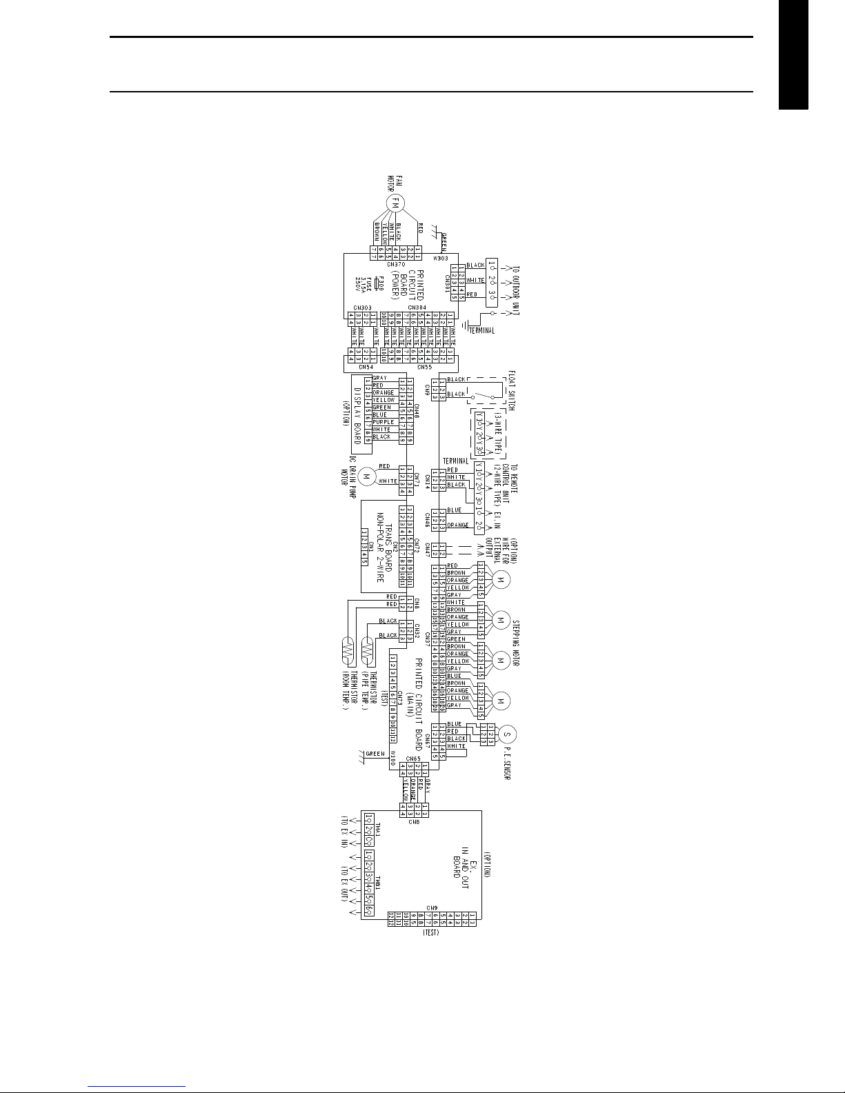
5. Wiring diagram
5-1. Models: AUXG18LRLB, AUXG24LRLB, AUXG30LRLB,
AUXG36LRLB, AUXG45LRLB, and AUXG54LRLB
Page 28
- 22 -
CASSETTE TYPE
AUXG18-54LRLB
6. Capacity table
Capacity tables show each of following values calculated based on the outdoor temperature and the
indoor temperature, under given Airflow Rate (AFR):
For cooling capacity: Total Capacity (TC), Sensible Heat Capacity (SHC), and Input Power (IP)
For heating capacity: Total Capacity (TC) and Input Power (IP)
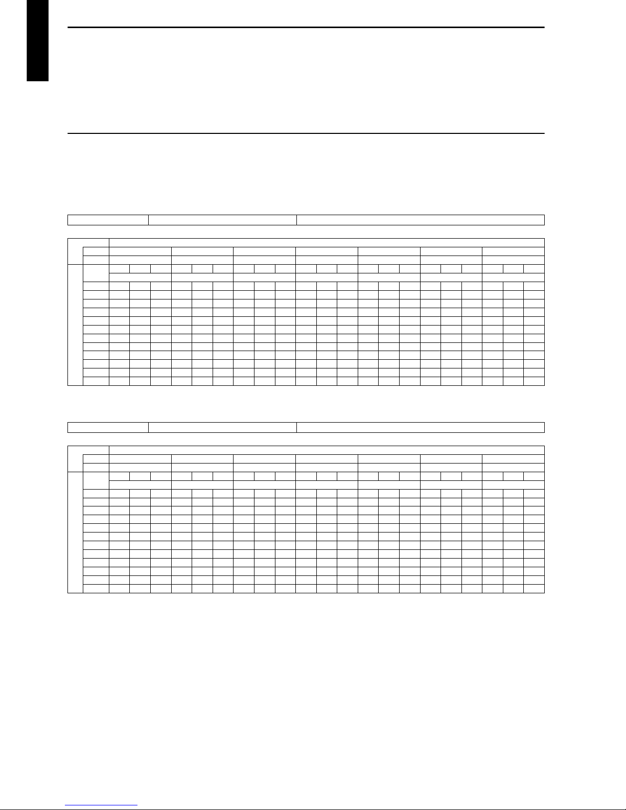
6-1. Cooling capacity
NOTE: Values mentioned in the table are calculated based on the maximum capacity.
Model: AUXG18LRLB
Model: AUXG24LRLB
AFR
m3/h
1,050
Indoor temperature
°CDB 18 21 23 25 27 29 32
°CWB 12 15 16 18 19 21 23
Outdoor temperature
°CDB
TC SHC IP TC SHC IP TC SHC IP TC SHC IP TC SHC IP TC SHC IP TC SHC IP
kW kW kW kW kW kW kW
-15 4.88 4.10 0.25 5.44 4.11 0.25 5.63 4.47 0.25 6.00 4.48 0.26 6.19 4.85 0.26 6.55 4.83 0.26 6.92 5.14 0.26
-10 4.91 4.10 0.41 5.47 4.11 0.41 5.66 4.48 0.41 6.03 4.49 0.42 6.22 4.85 0.42 6.58 4.84 0.43 6.96 5.15 0.43
0 4.80 4.02 0.48 5.35 4.05 0.49 5.52 4.40 0.49 5.89 4.41 0.49 6.07 4.77 0.50 6.44 4.75 0.50 6.80 5.06 0.51
5 4.66 3.96 0.59 5.19 3.99 0.60 5.37 4.33 0.60 5.72 4.35 0.61 5.90 4.70 0.61 6.25 4.68 0.62 6.61 4.98 0.62
10 4.51 3.88 0.70 5.03 3.91 0.71 5.19 4.24 0.71 5.53 4.26 0.71 5.71 4.61 0.72 6.05 4.58 0.73 6.39 4.89 0.73
15 4.52 3.89 0.61 5.04 3.92 0.62 5.20 4.26 0.62 5.56 4.27 0.63 5.72 4.62 0.63 6.06 4.59 0.64 6.42 4.89 0.65
20 5.69 4.18 1.29 6.33 4.21 1.31 6.55 4.58 1.32 6.98 4.59 1.33 7.20 4.96 1.34 7.63 4.93 1.35 8.06 5.25 1.36
25 5.45 4.17 1.44 6.07 4.19 1.47 6.28 4.57 1.47 6.69 4.58 1.49 6.90 4.94 1.49 7.31 4.92 1.50 7.73 5.24 1.52
30 5.20 4.15 1.59 5.80 4.18 1.62 6.00 4.54 1.63 6.38 4.55 1.65 6.58 4.92 1.65 6.98 4.89 1.66 7.38 5.21 1.68
35 5.14 4.14 1.86 5.72 4.17 1.89 5.92 4.53 1.90 6.31 4.54 1.92 6.50 4.90 1.92 6.89 4.88 1.92 7.29 5.20 1.92
40 3.76 3.44 1.28 4.19 3.47 1.30 4.33 3.76 1.30 4.61 3.77 1.31 4.75 4.08 1.32 5.04 4.07 1.33 5.33 4.33 1.35
46 2.67 2.93 0.95 2.97 2.96 0.97 3.08 3.22 0.97 3.29 3.22 0.98 3.39 3.48 0.99 3.59 3.47 1.00 3.79 3.69 1.01
AFR
m3/h
1,150
Indoor temperature
°CDB 18 21 23 25 27 29 32
°CWB 12 15 16 18 19 21 23
Outdoor temperature
°CDB
TC SHC IP TC SHC IP TC SHC IP TC SHC IP TC SHC IP TC SHC IP TC SHC IP
kW kW kW kW kW kW kW
-15 5.59 4.51 0.36 6.23 4.53 0.36 6.44 4.93 0.37 6.86 4.94 0.37 7.07 5.34 0.38 7.50 5.32 0.38 7.92 5.67 0.38
-10 5.62 4.52 0.60 6.26 4.54 0.60 6.47 4.94 0.61 6.90 4.95 0.61 7.11 5.35 0.62 7.54 5.33 0.62 7.96 5.68 0.63
0 5.52 4.47 0.64 6.15 4.49 0.65 6.36 4.89 0.66 6.78 4.90 0.66 6.99 5.29 0.67 7.41 5.27 0.67 7.83 5.62 0.68
5 5.33 4.37 0.78 5.94 4.40 0.79 6.14 4.78 0.80 6.55 4.80 0.80 6.75 5.18 0.81 7.15 5.16 0.82 7.56 5.50 0.82
10 5.12 4.26 0.91 5.71 4.29 0.92 5.90 4.66 0.93 6.29 4.68 0.94 6.49 5.05 0.94 6.87 5.03 0.95 7.26 5.36 0.96
15 5.25 4.33 0.76 5.85 4.35 0.77 6.05 4.73 0.78 6.45 4.75 0.79 6.65 5.13 0.79 7.05 5.11 0.80 7.44 5.44 0.81
20 6.75 5.11 1.65 7.52 5.15 1.67 7.77 5.59 1.68 8.29 5.61 1.70 8.54 6.06 1.71 9.05 6.04 1.73 9.57 6.43 1.74
25 6.41 4.93 1.78 7.14 4.96 1.81 7.38 5.39 1.82 7.87 5.41 1.84 8.11 5.84 1.85 8.60 5.82 1.86 9.08 6.20 1.88
30 6.07 4.75 1.98 6.76 4.78 2.01 6.99 5.20 2.02 7.46 5.22 2.04 7.69 5.63 2.05 8.15 5.61 2.07 8.61 5.98 2.09
35 6.32 4.88 2.52 7.04 4.91 2.56 7.28 5.34 2.57 7.76 5.36 2.60 8.00 5.79 2.61 8.48 5.76 2.64 8.96 6.14 2.66
40 5.22 4.31 2.10 5.81 4.34 2.14 6.01 4.72 2.15 6.41 4.73 2.17 6.61 5.11 2.18 7.00 5.09 2.20 7.40 5.42 2.22
46 3.74 3.58 1.59 4.17 3.60 1.61 4.31 3.91 1.62 4.60 3.92 1.64 4.74 4.24 1.65 5.02 4.22 1.66 5.31 4.50 1.68
Page 29
- 23 -
CASSETTE TYPE
AUXG18-54LRLB
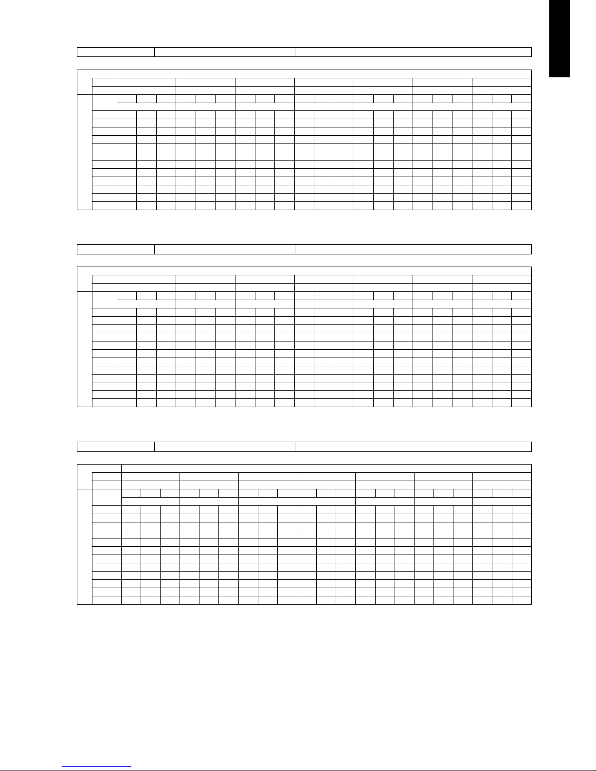
Model: AUXG30LRLB
Model: AUXG36LRLB
Model: AUXG45LRLB
AFR
m3/h
1,600
Indoor temperature
°CDB 18 21 23 25 27 29 32
°CWB 12 15 16 18 19 21 23
Outdoor temperature
°CDB
TC SHC IP TC SHC IP TC SHC IP TC SHC IP TC SHC IP TC SHC IP TC SHC IP
kW kW kW kW kW kW kW
-15 8.67 6.58 1.20 9.66 6.62 1.22 9.99 7.20 1.22 10.65 7.22 1.22 10.98 7.80 1.24 11.64 7.77 1.25 12.29 8.27 1.27
-10 8.52 6.38 1.64 9.49 6.42 1.66 9.81 6.98 1.67 10.46 7.00 1.69 10.79 7.56 1.70 11.44 7.53 1.72 12.08 8.02 1.73
0 8.12 6.26 2.11 9.04 6.30 2.15 9.35 6.85 2.16 9.97 6.87 2.18 10.28 7.42 2.19 10.90 7.39 2.21 11.51 7.87 2.23
5 7.99 6.11 2.14 8.90 6.14 2.17 9.21 6.68 2.19 9.81 6.70 2.21 10.12 7.23 2.22 10.73 7.20 2.24 11.33 7.68 2.26
10 7.96 6.19 2.19 8.87 6.23 2.23 9.17 6.77 2.24 9.77 6.79 2.26 10.07 7.34 2.27 10.67 7.31 2.29 11.28 7.79 2.32
15 8.63 6.48 2.41 9.62 6.52 2.45 9.95 7.09 2.46 10.60 7.11 2.49 10.93 7.68 2.50 11.59 7.65 2.53 12.24 8.14 2.55
20 9.82 7.03 2.97 10.94 7.07 3.01 11.31 7.69 3.03 12.06 7.71 3.06 12.43 8.33 3.08 13.18 8.30 3.11 13.92 8.84 3.14
25 9.48 6.89 3.31 10.56 6.93 3.36 10.92 7.53 3.38 11.64 7.56 3.41 12.00 8.16 3.43 12.72 8.13 3.46 13.44 8.66 3.50
30 8.81 6.70 3.35 9.81 6.74 3.39 10.15 7.32 3.41 10.81 7.35 3.44 11.15 7.93 3.46 11.82 7.90 3.50 12.49 8.42 3.53
35 7.90 6.12 3.35 8.80 6.16 3.40 9.10 6.69 3.42 9.70 6.71 3.45 10.00 7.25 3.47 10.60 7.22 3.51 11.20 7.69 3.54
40 6.16 5.13 2.94 6.86 5.16 2.99 7.09 5.61 3.00 7.56 5.63 3.04 7.80 6.08 3.05 8.27 6.06 3.08 8.73 6.45 3.11
46 5.44 4.92 2.91 6.06 4.95 2.96 6.27 5.39 2.97 6.68 5.40 3.00 6.89 5.83 3.02 7.30 5.81 3.05 7.71 6.19 3.08
AFR
m3/h
1,900
Indoor temperature
°CDB 18 21 23 25 27 29 32
°CWB 12 15 16 18 19 21 23
Outdoor temperature
°CDB
TC SHC IP TC SHC IP TC SHC IP TC SHC IP TC SHC IP TC SHC IP TC SHC IP
kW kW kW kW kW kW kW
-15 9.33 7.37 1.29 10.39 7.41 1.31 10.74 8.06 1.32 11.45 8.08 1.33 11.80 8.73 1.34 12.51 8.70 1.35 13.22 9.26 1.36
-10 9.22 7.23 1.69 10.27 7.27 1.71 10.62 7.90 1.72 11.32 7.93 1.74 11.67 8.56 1.75 12.37 8.53 1.77 13.07 9.08 1.78
0 8.77 7.13 2.18 9.77 7.17 2.22 10.10 7.80 2.23 10.77 7.82 2.25 11.10 8.45 2.26 11.77 8.41 2.29 12.44 8.96 2.31
5 8.69 6.98 2.25 9.68 7.02 2.28 10.01 7.64 2.29 10.67 7.66 2.32 11.00 8.27 2.33 11.66 8.24 2.35 12.32 8.78 2.38
10 8.62 7.06 2.25 9.60 7.10 2.29 9.93 7.72 2.30 10.58 7.75 2.32 10.91 8.37 2.34 11.56 8.33 2.36 12.22 8.88 2.38
15 9.17 7.17 2.42 10.21 7.22 2.46 10.56 7.85 2.47 11.25 7.87 2.50 11.60 8.50 2.51 12.30 8.47 2.54 13.00 9.02 2.56
20 10.70 7.92 2.99 11.92 7.97 3.03 12.33 8.66 3.05 13.14 8.69 3.08 13.54 9.39 3.10 14.36 9.35 3.13 15.17 9.96 3.16
25 10.64 8.02 3.32 11.86 8.06 3.38 12.26 8.77 3.39 13.07 8.79 3.43 13.47 9.50 3.45 14.28 9.46 3.48 15.09 10.08 3.51
30 10.24 7.76 4.05 11.40 7.81 4.11 11.79 8.49 4.13 12.57 8.51 4.17 12.96 9.19 4.19 13.73 9.16 4.24 14.51 9.75 4.28
35 8.85 6.78 4.03 9.86 6.82 4.10 10.19 7.42 4.12 10.86 7.44 4.16 11.20 8.04 4.18 11.87 8.01 4.22 12.54 8.53 4.27
40 6.80 5.96 3.09 7.58 6.00 3.14 7.84 6.52 3.16 8.35 6.54 3.19 8.61 7.07 3.20 9.13 7.04 3.24 9.65 7.50 3.27
46 6.11 5.84 2.96 6.81 5.87 3.01 7.04 6.39 3.02 7.50 6.41 3.05 7.74 6.92 3.07 8.20 6.89 3.10 8.67 7.34 3.13
AFR
m3/h
2,000
Indoor temperature
°CDB 18 21 23 25 27 29 32
°CWB 12 15 16 18 19 21 23
Outdoor temperature
°CDB
TC SHC IP TC SHC IP TC SHC IP TC SHC IP TC SHC IP TC SHC IP TC SHC IP
kW kW kW kW kW kW kW
-15 11.34 8.71 2.56 12.63 8.76 2.60 13.06 9.52 2.62 13.92 9.55 2.64 14.35 10.32 2.66 15.21 10.28 2.68 16.07 10.95 2.71
-10 11.44 8.70 2.46 12.74 8.75 2.50 13.17 9.51 2.51 14.04 9.55 2.54 14.48 10.31 2.55 15.35 10.27 2.58 16.21 10.94 2.60
0 11.55 8.77 2.23 12.87 8.83 2.26 13.31 9.60 2.28 14.18 9.63 2.30 14.62 10.40 2.31 15.50 10.35 2.33 16.38 11.03 2.36
5 11.37 8.78 2.30 12.67 8.84 2.34 13.10 9.61 2.35 13.97 9.64 2.37 14.40 10.41 2.39 15.26 10.37 2.41 16.12 11.04 2.43
10 11.11 8.78 2.49 12.37 8.83 2.53 12.79 9.60 2.54 13.64 9.63 2.57 14.06 10.40 2.58 14.90 10.36 2.61 15.74 11.04 2.63
15 10.84 8.68 2.69 12.07 8.74 2.73 12.48 9.50 2.74 13.31 9.53 2.77 13.72 10.29 2.78 14.54 10.25 2.81 15.37 10.92 2.84
20 11.22 8.69 3.15 12.49 8.74 3.20 12.92 9.50 3.22 13.77 9.53 3.25 14.20 10.29 3.27 15.05 10.25 3.30 15.90 10.92 3.33
25 11.10 8.78 3.36 12.36 8.83 3.41 12.79 9.60 3.43 13.63 9.63 3.46 14.05 10.40 3.48 14.89 10.36 3.51 15.74 11.03 3.55
30 11.34 8.84 4.27 12.63 8.89 4.34 13.06 9.67 4.36 13.92 9.70 4.41 14.35 10.48 4.43 15.21 10.43 4.43 16.07 11.11 4.43
35 11.06 8.82 4.53 12.32 8.87 4.60 12.74 9.64 4.62 13.58 9.68 4.67 14.00 10.45 4.69 14.84 10.41 4.69 15.68 11.09 4.69
40 8.79 7.66 3.92 9.79 7.83 3.98 10.13 8.52 4.00 10.80 8.54 4.04 11.13 9.23 4.06 11.80 9.19 4.06 12.47 9.79 4.06
46 6.69 6.63 3.24 7.45 6.87 3.29 7.71 7.47 3.31 8.22 7.49 3.34 8.47 8.09 3.36 8.98 8.06 3.36 9.49 8.58 3.36
Page 30
- 24 -
CASSETTE TYPE
AUXG18-54LRLB
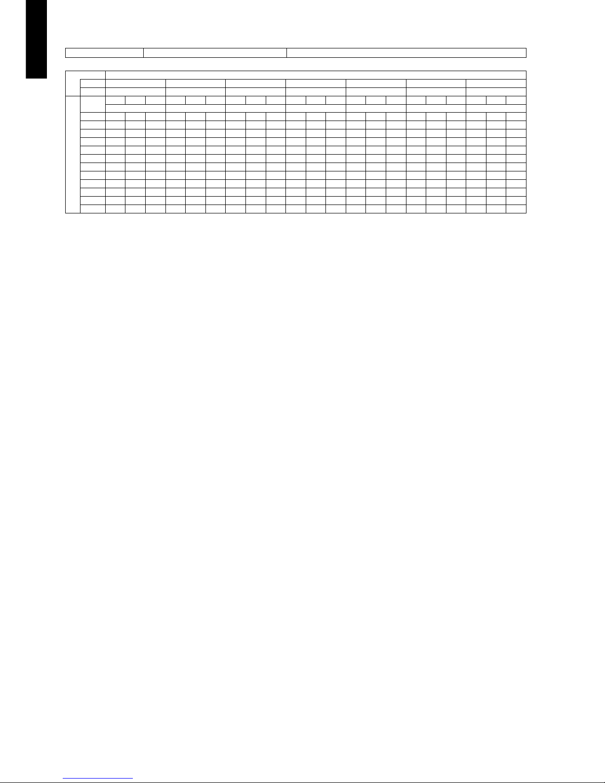
Model: AUXG54LRLB
AFR
m3/h
2,100
Indoor temperature
°CDB 18 21 23 25 27 29 32
°CWB 12 15 16 18 19 21 23
Outdoor temperature
°CDB
TC SHC IP TC SHC IP TC SHC IP TC SHC IP TC SHC IP TC SHC IP TC SHC IP
kW kW kW kW kW kW kW
-15 11.73 9.03 2.69 13.07 9.08 2.73 13.52 9.87 2.75 14.41 9.90 2.78 14.85 10.69 2.79 15.74 10.65 2.82 16.64 11.35 2.85
-10 11.72 9.04 2.59 13.06 9.10 2.63 13.50 9.89 2.64 14.39 9.92 2.67 14.84 10.71 2.68 15.73 10.67 2.71 16.62 11.37 2.73
0 11.84 9.12 2.33 13.19 9.17 2.36 13.64 9.97 2.37 14.54 10.01 2.40 14.99 10.81 2.41 15.89 10.76 2.43 16.78 11.46 2.46
5 11.60 8.96 2.42 12.92 9.02 2.46 13.37 9.80 2.47 14.25 9.83 2.50 14.69 10.62 2.51 15.57 10.58 2.54 16.45 11.27 2.56
10 11.44 8.90 2.54 12.74 8.95 2.58 13.18 9.73 2.59 14.04 9.76 2.62 14.48 10.54 2.63 15.35 10.50 2.66 16.22 11.18 2.68
15 11.22 8.99 2.81 12.50 9.04 2.85 12.92 9.83 2.86 13.77 9.86 2.89 14.20 10.65 2.91 15.05 10.61 2.93 15.90 11.30 2.96
20 12.06 9.55 3.73 13.43 9.61 3.79 13.89 10.45 3.81 14.81 10.48 3.85 15.26 11.32 3.87 16.18 11.27 3.90 17.10 12.01 3.94
25 11.82 9.10 4.31 13.17 9.15 4.38 13.62 9.95 4.40 14.52 9.98 4.45 14.97 10.78 4.47 15.86 10.73 4.51 16.76 11.44 4.56
30 11.62 8.98 4.52 12.95 9.04 4.59 13.39 9.82 4.61 14.27 9.86 4.66 14.71 10.64 4.68 15.59 10.60 4.68 16.48 11.29 4.68
35 11.46 8.89 4.75 12.76 8.95 4.82 13.20 9.73 4.85 14.07 9.76 4.90 14.50 10.54 4.92 15.37 10.50 4.92 16.24 11.18 4.92
40 9.11 8.03 3.94 10.15 8.21 4.00 10.49 8.93 4.02 11.18 8.96 4.06 11.53 9.67 4.08 12.22 9.63 4.08 12.91 10.26 4.08
46 6.94 6.91 3.26 7.73 7.16 3.31 7.99 7.78 3.33 8.52 7.81 3.36 8.78 8.43 3.38 9.31 8.40 3.38 9.83 8.94 3.38
Page 31

- 25 -
CASSETTE TYPE
AUXG18-54LRLB
6-2. Heating capacity
NOTE: Values mentioned in the table are calculated based on the maximum capacity.
Model: AUXG18LRLB
Model: AUXG24LRLB
Model: AUXG30LRLB
AFR
m3/h
1,050
Indoor temperature
°CDB 16 18 20 22 24
Outdoor temperature
°CDB °CWB
TC IP TC IP TC IP TC IP TC IP
kW kW kW kW kW
-15 -16 5.37 2.41 5.25 2.46 5.12 2.50 4.99 2.55 4.86 2.61
-10 -11 6.18 2.51 6.03 2.57 5.89 2.62 5.74 2.67 5.59 2.73
-5 -7 6.96 2.59 6.80 2.64 6.63 2.70 6.47 2.73 6.30 2.73
0 -2 7.89 2.62 7.70 2.67 7.51 2.73 7.33 2.73 7.13 2.73
5 3 8.63 2.61 8.42 2.66 8.22 2.72 8.01 2.73 7.81 2.73
7 6 8.39 2.24 8.20 2.28 8.00 2.33 7.80 2.38 7.59 2.42
10 8 8.66 2.22 8.45 2.27 8.24 2.31 8.04 2.36 7.83 2.41
15 10 7.77 1.91 7.59 1.94 7.40 1.99 7.21 2.02 7.03 2.07
20 15 7.31 1.50 7.13 1.53 6.96 1.56 6.79 1.59 6.54 1.60
24 18 7.45 1.49 7.27 1.52 7.09 1.55 6.92 1.58 6.74 1.61
AFR
m3/h
1,150
Indoor temperature
°CDB 16 18 20 22 24
Outdoor temperature
°CDB °CWB
TC IP TC IP TC IP TC IP TC IP
kW kW kW kW kW
-15 -16 6.15 2.84 6.01 2.90 5.86 2.96 5.72 3.01 5.57 3.07
-10 -11 6.92 3.03 6.75 3.09 6.59 3.15 6.42 3.22 6.26 3.28
-5 -7 7.64 3.02 7.45 3.08 7.27 3.14 7.09 3.20 6.91 3.27
0 -2 8.59 3.00 8.38 3.06 8.18 3.12 7.97 3.18 7.77 3.25
5 3 9.54 3.02 9.31 3.08 9.09 3.14 8.86 3.20 8.63 3.27
7 6 9.55 2.69 9.33 2.74 9.10 2.80 8.87 2.86 8.64 2.91
10 8 9.87 2.69 9.63 2.75 9.40 2.80 9.16 2.86 8.93 2.92
15 10 8.97 2.07 8.76 2.12 8.54 2.16 8.33 2.20 8.11 2.25
20 15 8.23 1.63 8.03 1.66 7.84 1.69 7.64 1.73 7.45 1.76
24 18 8.52 1.62 8.32 1.66 8.12 1.69 7.92 1.73 7.71 1.76
AFR
m
3
/h
1,600
Indoor temperature
°CDB 16 18 20 22 24
Outdoor temperature
°CDB °CWB
TC IP TC IP TC IP TC IP TC IP
kW kW kW kW kW
-15 -16 8.34 3.37 8.14 3.44 7.94 3.51 7.75 3.58 7.55 3.65
-10 -11 8.79 3.38 8.58 3.45 8.37 3.52 8.16 3.59 7.95 3.66
-5 -7 9.55 3.41 9.32 3.48 9.09 3.55 8.86 3.62 8.64 3.69
0 -2 10.12 3.37 9.88 3.44 9.64 3.51 9.40 3.58 9.16 3.65
5 3 11.23 3.35 10.96 3.42 10.69 3.49 10.43 3.56 10.16 3.62
7 6 11.76 3.33 11.48 3.40 11.20 3.47 10.92 3.54 10.64 3.61
10 8 12.12 3.30 11.83 3.37 11.54 3.44 11.25 3.51 10.96 3.57
15 10 10.86 2.52 10.60 2.57 10.34 2.62 10.09 2.67 9.83 2.71
20 15 10.87 2.23 10.61 2.28 10.35 2.33 10.09 2.37 9.83 2.41
24 18 11.31 2.25 11.04 2.30 10.78 2.34 10.51 2.39 10.24 2.43
Page 32

- 26 -
CASSETTE TYPE
AUXG18-54LRLB
Model: AUXG36LRLB
Model: AUXG45LRLB
Model: AUXG54LRLB
AFR
m3/h
1,900
Indoor temperature
°CDB 16 18 20 22 24
Outdoor temperature
°CDB °CWB
TC IP TC IP TC IP TC IP TC IP
kW kW kW kW kW
-15 -16 9.63 3.92 9.40 4.00 9.17 4.08 8.94 4.17 8.71 4.25
-10 -11 9.70 3.96 9.47 4.04 9.24 4.13 9.01 4.21 8.77 4.29
-5 -7 10.69 4.07 10.43 4.16 10.18 4.24 9.92 4.33 9.67 4.41
0 -2 12.54 3.99 12.24 4.08 11.94 4.16 11.64 4.24 11.34 4.33
5 3 13.18 3.81 12.87 3.89 12.55 3.97 12.24 4.05 11.92 4.13
7 6 13.34 3.36 13.02 3.43 12.70 3.50 12.38 3.57 12.07 3.64
10 8 13.74 3.19 13.42 3.26 13.09 3.33 12.76 3.39 12.43 3.46
15 10 12.26 2.55 11.97 2.60 11.67 2.65 11.38 2.71 11.09 2.75
20 15 12.28 2.26 11.99 2.31 11.69 2.36 11.40 2.40 11.11 2.44
24 18 12.80 2.28 12.49 2.32 12.19 2.37 11.88 2.42 11.58 2.46
AFR
m3/h
2,000
Indoor temperature
°CDB 16 18 20 22 24
Outdoor temperature
°CDB °CWB
TC IP TC IP TC IP TC IP TC IP
kW kW kW kW kW
-15 -16 10.90 4.14 10.64 4.22 10.38 4.31 10.12 4.40 9.86 4.48
-10 -11 11.86 4.29 11.57 4.38 11.29 4.47 11.01 4.56 10.73 4.65
-5 -7 12.96 4.25 12.65 4.34 12.34 4.43 12.03 4.43 11.73 4.43
0 -2 14.01 4.25 13.68 4.34 13.35 4.43 13.01 4.43 12.68 4.43
5 3 15.51 4.25 15.14 4.34 14.77 4.43 14.40 4.43 14.03 4.43
7 6 17.01 4.25 16.61 4.34 16.20 4.43 15.80 4.43 15.39 4.43
10 8 17.29 4.25 16.88 4.34 16.46 4.43 16.05 4.43 15.64 4.43
15 10 16.80 3.80 16.40 3.88 16.00 3.96 15.60 3.96 15.20 3.96
20 15 16.27 3.80 15.88 3.88 15.49 3.96 15.10 3.96 14.72 3.96
24 18 16.79 3.26 16.39 3.33 15.99 3.40 15.60 3.40 15.20 3.40
AFR
m3/h
2,100
Indoor temperature
°CDB 16 18 20 22 24
Outdoor temperature
°CDB °CWB
TC IP TC IP TC IP TC IP TC IP
kW kW kW kW kW
-15 -16 11.00 4.16 10.73 4.24 10.47 4.33 10.21 4.42 9.95 4.50
-10 -11 12.08 4.31 11.79 4.40 11.50 4.49 11.22 4.58 10.93 4.67
-5 -7 13.30 4.49 12.99 4.59 12.67 4.68 12.35 4.68 12.04 4.68
0 -2 14.44 4.49 14.10 4.59 13.75 4.68 13.41 4.68 13.07 4.68
5 3 16.01 4.49 15.62 4.59 15.24 4.68 14.86 4.68 14.48 4.68
7 6 17.33 4.49 16.91 4.59 16.50 4.68 16.09 4.68 15.68 4.68
10 8 17.61 4.49 17.19 4.59 16.77 4.68 16.35 4.68 15.93 4.68
15 10 16.97 3.82 16.57 3.90 16.16 3.98 15.76 3.98 15.35 3.98
20 15 16.43 3.37 16.04 3.44 15.65 3.51 15.25 3.51 14.86 3.51
24 18 16.96 3.37 16.56 3.44 16.15 3.51 15.75 3.51 15.35 3.51
Page 33

- 27 -
CASSETTE TYPE
AUXG18-54LRLB
7. Fan performance
7-1. Air velocity distributions
Model: AUXG18LRLB (4-way air outlet)
Measuring conditions
Fan speed Operation mode
HIGH FAN
Top view
Vertical airflow direction louver: position 1
Side view
Vertical airflow direction louver: position 1
Side view
Vertical airflow direction louver: position 2
Side view
Vertical airflow direction louver: position 4
(m)
(m)
Unit: m/s
3
2
1
0
3
2
1
11
1
1
1
1
22
2
2
2
2
03344556 67 7
0.5
0.5
0.5
0.5
0.25
0.25
(m)
(m)
Unit: m/s
3.2
2
1
0
11
1
1
22
22
03344556 67 7
0.5 0.5
0.25 0.25
(m)
(m)
Unit: m/s
3.2
2
1
0
11
1
1
22
22
03344556 67 7
0.5 0.5
0.25 0.25
(m)
(m)
Unit: m/s
3.2
2
1
0
112203344556 67 7
0.25
0.5
1
2
0.5
0.25
1
2
Page 34

- 28 -
CASSETTE TYPE
AUXG18-54LRLB
Model: AUXG24LRLB (4-way air outlet)
Measuring conditions
Fan speed Operation mode
HIGH FAN
Top vi ew
Vertical airflow direction louver: position 1
Side view
Vertical airflow direction louver: position 1
Side view
Vertical airflow direction louver: position 2
Side view
Vertical airflow direction louver: position 4
(m)
(m)
Unit: m/s
3
2
1
0
3
2
1
11
1
1
1
1
22
2
2
2
2
03344556 67 7
0.5
0.5
0.5
0.5
0.25
0.25
(m)
(m)
Unit: m/s
3.2
2
1
0
112203344556 67 7
0.25
0.5
1
2
0.5
0.25
1
2
(m)
(m)
Unit: m/s
3.2
2
1
0
112203344556 67 7
0.25
0.5
1
2
0.5
0.25
1
2
(m)
(m)
Unit: m/s
3.2
2
1
0
112203344556 67 7
0.25
0.5
1
2
0.5
0.25
1
2
Page 35

- 29 -
CASSETTE TYPE
AUXG18-54LRLB
Model: AUXG30LRLB (4-way air outlet)
Measuring conditions
Fan speed Operation mode
HIGH FAN
Top view
Vertical airflow direction louver: position 1
Side view
Vertical airflow direction louver: position 1
Side view
Vertical airflow direction louver: position 2
Side view
Vertical airflow direction louver: position 4
(m)
(m)
Unit: m/s
3
2
1
0
3
2
1
11
1
1
1
1
22
2
2
2
2
03344556 67 7
0.5 0.5
0.5
0.5
0.25 0.25
(m)
(m)
Unit: m/s
3.2
2
1
0
11
11
22
22
03344556 67 7
0.5 0.5
0.25
0.25
(m)
(m)
Unit: m/s
3.2
2
1
0
11
11
22
22
03344556 67 7
0.5 0.5
0.25 0.25
(m)
(m)
Unit: m/s
3.2
2
1
0
112203344556 67 7
0.25
0.5
1
2
0.5
0.25
1
2
Page 36

- 30 -
CASSETTE TYPE
AUXG18-54LRLB
Model: AUXG36LRLB (4-way air outlet)
Measuring conditions
Fan speed Operation mode
HIGH FAN
Top vi ew
Vertical airflow direction louver: position 1
Side view
Vertical airflow direction louver: position 1
Side view
Vertical airflow direction louver: position 2
Side view
Vertical airflow direction louver: position 4
(m)
(m)
Unit: m/s
3
2
1
0
3
2
1
11
1
22
2
03344556 67 7
0.5
0.25
1
2
0.5
1
2
0.5
0.25
2
1
0.5
(m)
(m)
Unit: m/s
3.2
2
1
0
112203344556 67 7
0.25
0.5
1
2
0.5
0.25
1
2
(m)
(m)
Unit: m/s
3.2
2
1
0
112203344556 67 7
0.25
0.5
1
2
0.5
0.25
1
2
(m)
(m)
Unit: m/s
3.2
2
1
0
112203344556 67 7
0.25
0.5
1
2
0.5
0.25
1
2
Page 37

- 31 -
CASSETTE TYPE
AUXG18-54LRLB
Model: AUXG45LRLB (4-way air outlet)
Measuring conditions
Fan speed Operation mode
HIGH FAN
Top view
Vertical airflow direction louver: position 1
Side view
Vertical airflow direction louver: position 1
Side view
Vertical airflow direction louver: position 2
Side view
Vertical airflow direction louver: position 4
(m)
(m)
Unit: m/s
3
2
1
0
3
2
1
11
1
22
2
03344556 67 7
0.5
0.25
1
2
0.5
1
2
0.5
0.25
2
1
0.5
(m)
(m)
Unit: m/s
3.2
2
1
0
112203344556 67 7
0.25
0.5
1
2
0.5
0.25
1
2
(m)
(m)
Unit: m/s
3.2
2
1
0
112203344556 67 7
0.25
0.5
1
2
0.5
0.25
1
2
(m)
(m)
Unit: m/s
3.2
2
1
0
112203344556 67 7
0.25
0.5
1
2
0.5
0.25
1
2
Page 38

- 32 -
CASSETTE TYPE
AUXG18-54LRLB
Model: AUXG54LRLB (4-way air outlet)
Measuring conditions
Fan speed Operation mode
HIGH FAN
Top vi ew
Vertical airflow direction louver: position 1
Side view
Vertical airflow direction louver: position 1
Side view
Vertical airflow direction louver: position 2
Side view
Vertical airflow direction louver: position 4
(m)
(m)
Unit: m/s
3
2
1
0
3
2
1
11
1
22
2
03344556 67 7
0.5
0.25
1
2
0.5
1
2
0.5
0.25
2
1
0.5
(m)
(m)
Unit: m/s
3.2
2
1
0
112203344556 67 7
0.25
0.5
1
2
0.5
0.25
1
2
(m)
(m)
Unit: m/s
3.2
2
1
0
112203344556 67 7
0.25
0.5
1
2
0.5
0.25
1
2
(m)
(m)
Unit: m/s
3.2
2
1
0
112203344556 67 7
0.25
0.5
1
2
0.5
0.25
1
2
Page 39

- 33 -
CASSETTE TYPE
AUXG18-54LRLB
Model: AUXG18LRLB (3-way air outlet)
Measuring conditions
Fan speed Operation mode
HIGH FAN
Top view
Vertical airflow direction louver: position 1
Side view
Vertical airflow direction louver: position 1
Side view
Vertical airflow direction louver: position 2
Side view
Vertical airflow direction louver: position 4
(m)
(m)
Unit: m/s
3
2
1
0
3
2
1
11
1
22
2
03344556 67 7
0.5 0.25
1
2
0.5
1
2
0.5
0.25
(m)
(m)
Unit: m/s
3.2
2
1
0
112203344556 67 7
0.25
0.5
1
2
0.5
0.25
1
2
(m)
(m)
Unit: m/s
3.2
2
1
0
112203344556 67 7
0.25
0.5
1
2
0.5
0.25
1
2
(m)
(m)
Unit: m/s
3.2
2
1
0
112203344556 67 7
0.25
0.5
1
2
0.5
0.25
1
2
Page 40

- 34 -
CASSETTE TYPE
AUXG18-54LRLB
Model: AUXG24LRLB (3-way air outlet)
Measuring conditions
Fan speed Operation mode
HIGH FAN
Top vi ew
Vertical airflow direction louver: position 1
Side view
Vertical airflow direction louver: position 1
Side view
Vertical airflow direction louver: position 2
Side view
Vertical airflow direction louver: position 4
(m)
(m)
Unit: m/s
3
2
1
0
3
2
1
11
1
22
2
03344556 67 7
0.5
0.25
1
2
0.5
1
2
0.5
0.25
(m)
(m)
Unit: m/s
3.2
2
1
0
112203344556 67 7
0.25
0.5
1
2
0.5
0.25
1
2
(m)
(m)
Unit: m/s
3.2
2
1
0
112203344556 67 7
0.25
0.5
1
2
0.5
0.25
1
2
(m)
(m)
Unit: m/s
3.2
2
1
0
112203344556 67 7
0.25
0.5
1
2
0.5
0.25
1
2
Page 41

- 35 -
CASSETTE TYPE
AUXG18-54LRLB
Model: AUXG30LRLB (3-way air outlet)
Measuring conditions
Fan speed Operation mode
HIGH FAN
Top view
Vertical airflow direction louver: position 1
Side view
Vertical airflow direction louver: position 1
Side view
Vertical airflow direction louver: position 2
Side view
Vertical airflow direction louver: position 4
(m)
(m)
Unit: m/s
3
2
1
0
3
2
1
11
1
22
2
03344556 67 7
0.5
0.25
1
2
0.5
1
2
0.5
0.25
(m)
(m)
Unit: m/s
3.2
2
1
0
112203344556 67 7
0.25
0.5
1
2
0.5
0.25
1
2
(m)
(m)
Unit: m/s
3.2
2
1
0
112203344556 67 7
0.25
0.5
1
2
0.5
0.25
1
2
(m)
(m)
Unit: m/s
3.2
2
1
0
112203344556 67 7
0.25
0.5
1
2
0.5
0.25
1
2
Page 42

- 36 -
CASSETTE TYPE
AUXG18-54LRLB
Model: AUXG36LRLB (3-way air outlet)
Measuring conditions
Fan speed Operation mode
HIGH FAN
Top vi ew
Vertical airflow direction louver: position 1
Side view
Vertical airflow direction louver: position 1
Side view
Vertical airflow direction louver: position 2
Side view
Vertical airflow direction louver: position 4
(m)
(m)
Unit: m/s
3
2
1
0
3
2
1
11
1
22
2
03344556 67 7
0.5
0.25
1
2
0.5
0.25
2
1
0.5
(m)
(m)
Unit: m/s
3.2
2
1
0
112203344556 67 7
0.25
0.5
1
2
0.5
0.25
1
2
(m)
(m)
Unit: m/s
3.2
2
1
0
112203344556 67 7
0.25
0.5
1
2
0.5
0.25
1
2
(m)
(m)
Unit: m/s
3.2
2
1
0
112203344556 67 7
0.25
0.5
1
2
0.5
0.25
1
2
Page 43

- 37 -
CASSETTE TYPE
AUXG18-54LRLB
Model: AUXG45LRLB (3-way air outlet)
Measuring conditions
Fan speed Operation mode
HIGH FAN
Top view
Vertical airflow direction louver: position 1
Side view
Vertical airflow direction louver: position 1
Side view
Vertical airflow direction louver: position 2
Side view
Vertical airflow direction louver: position 4
(m)
(m)
Unit: m/s
3
2
1
0
3
2
1
11
1
22
2
03344556 67 7
0.5
0.25
1
2
0.5
0.25
2
10.5
(m)
(m)
Unit: m/s
3.2
2
1
0
112203344556 67 7
0.25
0.5
1
2
0.5
0.25
1
2
(m)
(m)
Unit: m/s
3.2
2
1
0
112203344556 67 7
0.25
0.5
1
2
0.5
0.25
1
2
(m)
(m)
Unit: m/s
3.2
2
1
0
112203344556 67 7
0.25
0.5
1
2
0.5
0.25
1
2
Page 44

- 38 -
CASSETTE TYPE
AUXG18-54LRLB
Model: AUXG54LRLB (3-way air outlet)
Measuring conditions
Fan speed Operation mode
HIGH FAN
Top vi ew
Vertical airflow direction louver: position 1
Side view
Vertical airflow direction louver: position 1
Side view
Vertical airflow direction louver: position 2
Side view
Vertical airflow direction louver: position 4
(m)
(m)
Unit: m/s
3
2
1
0
3
2
1
11
1
22
2
03344556 67 7
0.5
0.25
1
2
0.5
0.25
2
1
0.5
(m)
(m)
Unit: m/s
3.2
2
1
0
112203344556 67 7
0.25
0.5
1
2
0.5
0.25
1
2
(m)
(m)
Unit: m/s
3.2
2
1
0
112203344556 67 7
0.25
0.5
1
2
0.5
0.25
1
2
(m)
(m)
Unit: m/s
3.2
2
1
0
112203344556 67 7
0.25
0.5
1
2
0.5
0.25
1
2
Page 45

- 39 -
CASSETTE TYPE
AUXG18-54LRLB
7-2. Airflow
Model: AUXG18LRLB (4-way outlet)
Cooling/Heating
Model: AUXG24LRLB (4-way outlet)
Cooling/Heating
Fan speed Airflow
HIGH
m
3
/h
1,050
l/s 292
CFM 618
MED
m
3
/h
960
l/s 267
CFM 565
LOW
m
3
/h
900
l/s 250
CFM 530
QUIET
m
3
/h
780
l/s 217
CFM 459
Fan speed Airflow
HIGH
m
3
/h
1,150
l/s 319
CFM 677
MED
m
3
/h
1,050
l/s 292
CFM 618
LOW
m
3
/h
980
l/s 272
CFM 577
QUIET
m
3
/h
870
l/s 242
CFM 512
Page 46

- 40 -
CASSETTE TYPE
AUXG18-54LRLB
Model: AUXG30LRLB (4-way outlet)
Cooling/Heating
Model: AUXG36LRLB (4-way outlet)
Cooling/Heating
Model: AUXG45LRLB (4-way outlet)
Cooling/Heating
Fan speed Airflow
HIGH
m
3
/h
1,600
l/s 444
CFM 942
MED
m
3
/h
1,400
l/s 389
CFM 824
LOW
m
3
/h
1,270
l/s 353
CFM 748
QUIET
m
3
/h
1,150
l/s 319
CFM 677
Fan speed Airflow
HIGH
m
3
/h
1,900
l/s 528
CFM 1,118
MED
m
3
/h
1,590
l/s 442
CFM 936
LOW
m
3
/h
1,420
l/s 394
CFM 836
QUIET
m
3
/h
1,180
l/s 328
CFM 695
Fan speed Airflow
HIGH
m
3
/h
2,000
l/s 556
CFM 1,177
MED
m
3
/h
1,650
l/s 458
CFM 971
LOW
m
3
/h
1,460
l/s 406
CFM 859
QUIET
m
3
/h
1,300
l/s 361
CFM 765
Page 47

- 41 -
CASSETTE TYPE
AUXG18-54LRLB
Model: AUXG54LRLB (4-way outlet)
Cooling/Heating
Fan speed Airflow
HIGH
m
3
/h
2,100
l/s 583
CFM 1,236
MED
m
3
/h
1,780
l/s 494
CFM 1,048
LOW
m
3
/h
1,600
l/s 444
CFM 942
QUIET
m
3
/h
1,320
l/s 367
CFM 777
Page 48

- 42 -
CASSETTE TYPE
AUXG18-54LRLB
Model: AUXG18LRLB (3-way outlet)
Cooling/Heating
Model: AUXG24LRLB (3-way outlet)
Cooling/Heating
Fan speed Airflow
HIGH
m
3
/h
915
l/s 254
CFM 539
MED
m
3
/h
835
l/s 232
CFM 491
LOW
m
3
/h
785
l/s 218
CFM 462
QUIET
m
3
/h
680
l/s 189
CFM 400
Fan speed Airflow
HIGH
m
3
/h
1,000
l/s 278
CFM 589
MED
m
3
/h
915
l/s 254
CFM 538
LOW
m
3
/h
850
l/s 236
CFM 500
QUIET
m
3
/h
755
l/s 210
CFM 445
Page 49

- 43 -
CASSETTE TYPE
AUXG18-54LRLB
Model: AUXG30LRLB (3-way outlet)
Cooling/Heating
Model: AUXG36LRLB (3-way outlet)
Cooling/Heating
Model: AUXG45LRLB (3-way outlet)
Cooling/Heating
Fan speed Airflow
HIGH
m
3
/h
1,390
l/s 386
CFM 818
MED
m
3
/h
1,220
l/s 339
CFM 719
LOW
m
3
/h
1,100
l/s 306
CFM 648
QUIET
m
3
/h
1,000
l/s 278
CFM 589
Fan speed Airflow
HIGH
m
3
/h
1,660
l/s 461
CFM 978
MED
m
3
/h
1,390
l/s 386
CFM 819
LOW
m
3
/h
1,240
l/s 344
CFM 730
QUIET
m
3
/h
1,030
l/s 286
CFM 607
Fan speed Airflow
HIGH
m
3
/h
1,740
l/s 483
CFM 1,025
MED
m
3
/h
1,440
l/s 400
CFM 848
LOW
m
3
/h
1,270
l/s 353
CFM 748
QUIET
m
3
/h
1,130
l/s 314
CFM 666
Page 50

- 44 -
CASSETTE TYPE
AUXG18-54LRLB
Model: AUXG54LRLB (3-way outlet)
Cooling/Heating
Fan speed Airflow
HIGH
m
3
/h
1,830
l/s 508
CFM 1,078
MED
m
3
/h
1,550
l/s 431
CFM 913
LOW
m
3
/h
1,390
l/s 386
CFM 819
QUIET
m
3
/h
1,150
l/s 319
CFM 677
Page 51

- 45 -
CASSETTE TYPE
AUXG18-54LRLB
7-3. Fresh-air characteristics
Airflow volume: static pressure of fresh-air intake characteris-
tics
Installation
Airflow (m3/h)
0
20
40
60
80
100
120
0 1020304050
Duct static pressure (Pa)
Duct (inside
diameter: ø 95 mm)
Static pressure required
to take in fresh-air
Duct fan
280
185
2.5 screw hole (4 places)
95
81
81
Fresh-air inlet position
View (A)
Drain pipe
Refrigerant pipe
Top view
Fresh-air inlet position (A)
Cut-out hole
Unit: mm
Duct flange *2
Flexible duct *2
Fan *2
Flexible duct *2
Insulation *1
*1: In case of fresh-air intake, remove the insulation.
*2: Locally-purchased parts
Fresh-air inlet position
Page 52

- 46 -
CASSETTE TYPE
AUXG18-54LRLB
7-4. Duct connection
Outlet air
Model: AUXG18LRLB
Model: AUXG24LRLB
Model: AUXG30LRLB
L
Duct (inside size:
350 mm 100 mm)
0
10
20
30
40
50
60
70
80
90
100
02468101214
Duct static pressure (Pa)
Airflow (m3/min)
L=10m
L=5m
L=1m
Fan Speed
Quiet 2-way
Fan Speed
High 2-way
Fan Speed
Quiet 1-way
Fan Speed
High 1-way
0
10
20
30
40
50
60
70
80
90
100
02468101214
Duct static pressure (Pa)
Airflow (m3/min)
L=10m
L=5m
L=1m
Fan Speed
Quiet 2-way
Fan Speed
Quiet 1-way
Fan Speed
High 2-way
Fan Speed
High 1-way
L=10m
L=5m
L=1m
Fan Speed
Quiet 2-way
Fan Speed
Quiet 1-way
Fan Speed
High 1-way
Fan Speed
High 2-way
0
10
20
30
40
50
60
70
80
90
100
02468101214
Duct static pressure (Pa)
Airflow (m3/min)
Page 53

- 47 -
CASSETTE TYPE
AUXG18-54LRLB
Model: AUXG36LRLB
Model: AUXG45LRLB
Model: AUXG54LRLB
0
10
20
30
40
50
60
70
80
90
100
0 2 4 6 8 10 12 14
Duct static pressure (Pa)
Airflow (m3/min)
Fan Speed
Quiet 1-way
Fan Speed
Quiet 2-way
Fan Speed
High 2-way
Fan Speed
High 1-way
L=10m
L=5m
L=1m
0
10
20
30
40
50
60
70
80
90
100
02468101214
Duct static pressure (Pa)
Airflow (m3/min)
Fan Speed
High 1-way
Fan Speed
High 2-way
Fan Speed
Quiet 1-way
Fan Speed
Quiet 2-way
L=10m
L=5m
L=1m
Airflow (m3/min)
0
10
20
30
40
50
60
70
80
90
100
0 2 4 6 8 10 12 14
Duct static pressure (Pa)
Fan Speed
High 2-way
Fan Speed
Quiet 2-way
Fan Speed
Quiet 1-way
Fan Speed
High 1-way
L=10m
L=5m
L=1m
Page 54

- 48 -
CASSETTE TYPE
AUXG18-54LRLB
Precautions on air-outlet duct connection
• Connect the air-outlet duct to maximum 2 directions among the 4-duct connecting directions.
!
CAUTION
Do not connect ducts at 3 or more directions.
• When installing air-outlet duct in 2 directions, connect the ducts in a straight line.
• Once the ducted direction is decided, be sure to close the outlet in the direction.
Use optional Air outlet shutter plate (UTR-YDZK) to close the outlet.
A
B
C
D
Air-outlet duct
Air-outlet duct
CloseClose
Air-outlet duct
Air-outlet duct
Close
Close
Duct (locally purchased)
Close the outlet here.
Page 55

- 49 -
CASSETTE TYPE
AUXG18-54LRLB
8. Operation noise (sound pressure)
8-1. Noise level curve
Model: AUXG18LRLB
Cooling Heating
Model: AUXG24LRLB
Cooling Heating
Measuring conditions
Ceiling height Outlet directions
Standard 4-way air outlet
0
10
20
30
40
50
60
70
80
63 125 250 500 1000 2000 4000 8000
Octave band sound pressure level, dB:(0dB=20μPa)
Octave band center frequency ,Hz
NC-65
NC-60
NC-55
NC-50
NC-45
NC-40
NC-35
NC-30
NC-25
NC-20
NC-15
High
Quiet
0
10
20
30
40
50
60
70
80
63 125 250 500 1000 2000 4000 8000
Octave band sound pressure level, dB:(0dB=20μPa)
Octave band center frequency ,Hz
NC-65
NC-60
NC-55
NC-50
NC-45
NC-40
NC-35
NC-30
NC-25
NC-20
NC-15
High
Quiet
0
10
20
30
40
50
60
70
80
63 125 250 500 1000 2000 4000 8000
Octave band sound pressure level, dB:(0dB=20μPa)
Octave band center frequency ,Hz
NC-65
NC-60
NC-55
NC-50
NC-45
NC-40
NC-35
NC-30
NC-25
NC-20
NC-15
High
Quiet
0
10
20
30
40
50
60
70
80
63 125 250 500 1000 2000 4000 8000
Octave band sound pressure level, dB:(0dB=20μPa)
Octave band center frequency ,Hz
NC-65
NC-60
NC-55
NC-50
NC-45
NC-40
NC-35
NC-30
NC-25
NC-20
NC-15
High
Quiet
Page 56

- 50 -
CASSETTE TYPE
AUXG18-54LRLB
Model: AUXG30LRLB
Cooling Heating
Model: AUXG36LRLB
Cooling Heating
0
10
20
30
40
50
60
70
80
63 125 250 500 1000 2000 4000 8000
Octave band sound pressure level, dB:(0dB=20μPa)
Octave band center frequency ,Hz
NC-65
NC-60
NC-55
NC-50
NC-45
NC-40
NC-35
NC-30
NC-25
NC-20
NC-15
High
Quiet
0
10
20
30
40
50
60
70
80
63 125 250 500 1000 200 0 4000 8000
Octave band sound pressure level, dB:(0dB=20μPa)
Octave band center frequency ,Hz
NC-65
NC-60
NC-55
NC-50
NC-45
NC-40
NC-35
NC-30
NC-25
NC-20
NC-15
High
Quiet
0
10
20
30
40
50
60
70
80
63 125 250 500 1000 2000 4000 8000
Octave band sound pressure level, dB:(0dB=20μPa)
Octave band center frequency ,Hz
NC-65
NC-60
NC-55
NC-50
NC-45
NC-40
NC-35
NC-30
NC-25
NC-20
NC-15
High
Quiet
0
10
20
30
40
50
60
70
80
63 125 250 500 1000 2000 4000 8000
Octave band sound pressure level, dB:(0dB=20μPa)
Octave band center frequency ,Hz
NC-65
NC-60
NC-55
NC-50
NC-45
NC-40
NC-35
NC-30
NC-25
NC-20
NC-15
-
High
Quiet
Page 57

- 51 -
CASSETTE TYPE
AUXG18-54LRLB
Model: AUXG45LRLB
Cooling Heating
Model: AUXG54LRLB
Cooling Heating
0
10
20
30
40
50
60
70
80
63 125 250 500 1000 2000 4000 8000
Octave band sound pressure level, dB:(0dB=20μPa)
Octave band center frequency ,Hz
NC-65
NC-60
NC-55
NC-50
NC-45
NC-40
NC-35
NC-30
NC-25
NC-20
NC-15
-
High
Quiet
0
10
20
30
40
50
60
70
80
63 125 250 500 1000 2000 4000 8000
Octave band sound pressure level, dB:(0dB=20μPa)
Octave band center frequency ,Hz
NC-65
NC-60
NC-55
NC-50
NC-45
NC-40
NC-35
NC-30
NC-25
NC-20
NC-15
High
Quiet
0
10
20
30
40
50
60
70
80
63 125 250 500 1000 2000 4000 8000
Octave band sound pressure level, dB:(0dB=20μPa)
Octave band center frequency ,Hz
NC-65
NC-60
NC-55
NC-50
NC-45
NC-40
NC-35
NC-30
NC-25
NC-20
NC-15
High
Quiet
0
10
20
30
40
50
60
70
80
63 125 250 500 1000 2000 4000 8000
Octave band sound pressure level, dB:(0dB=20μPa)
Octave band center frequency ,Hz
NC-65
NC-60
NC-55
NC-50
NC-45
NC-40
NC-35
NC-30
NC-25
NC-20
NC-15
High
Quiet
Page 58

- 52 -
CASSETTE TYPE
AUXG18-54LRLB
8-2. Sound level check point
Microphone
Microphone
Center
1.5 m
Center
Page 59

- 53 -
CASSETTE TYPE
AUXG18-54LRLB
9. Safety devices
*: Printed Circuit Board
Type of protection Protection form
Model
AUXG18LRLB AUXG24LRLB
Circuit protection
Current fuse
(PCB*)
250 V, 3.15 A
Fan motor
protection
Thermal protection
program
Activate
125 ± 10 °C
Fan motor stop
Reset
120 ± 10 °C
Fan motor restart
Type of
protection
Protection form
Model
AUXG30LRLB AUXG36LRLB AUXG45LRLB AUXG54LRLB
Circuit
protection
Current fuse
(PCB*)
250 V, 3.15 A
Fan motor
protection
Thermal
protection
program
Activate
125 ± 10 °C
Fan motor stop
Reset
120 ± 10 °C
Fan motor restart
Page 60

- 54 -
CASSETTE TYPE
AUXG18-54LRLB
10. External input and output
10-1. External input
• “Operation/Stop” mode or "Forced stop" mode can be selected with function setting of indoor unit.
• A twisted pair cable (22AWG) should be used. Maximum length of cable is 150 m.
• The wire connection should be separate from the power cable line.
Indoor unit
Indoor unit functions such as Operation/Stop can be done by using indoor unit terminals.
*1: The switch can be used on the following condition: DC 12 V to 24 V, 1 mA to 15 mA.
PCB External input External output Connector Input select
Input
signal
External
connect kit
(Optional parts)
Indoor unit
Operation/Stop - Terminal Dry contact Edge -
-
Operation status
CN47 - - UTY-XWZXZG
Error status
Indoor unit fan
operation status
External heater
output
External
input and
output
(UTY-XCSX)
Operation/Stop
-
Input 1/
Input 2
Dry contact/
Apply voltage
Edge/
Pulse
-
Forced
thermostat off
Input 1 Edge
-
Operation status
Output 1
Output 2
Output 3
-- -
Error status
Indoor unit
status
External heater
output
Terminal
(Ext.in)
CN65
(Ext.in/out PCB)
CN47
(Ext.out)
Rotary switch
SW2
SW1
Fig. External input and output PCBFig. Indoor unit PCB
1
2
Terminal
PCB
Page 61

- 55 -
CASSETTE TYPE
AUXG18-54LRLB
External input and output PCB
The indoor unit Operation/Stop can be set by using the input terminal on the PCB.
Input select
Use either one of these types of terminals according to the application. (Both types of terminals
cannot be used simultaneously.)
• Dry contact
In case of internal power supply, set the slide switch of SW1 to "NON VOL" side.
*1: The switches can be used on the following condition: DC 12 V to 24 V, 1 mA to 15 mA.
• Apply voltage
In case of external power supply, set the slide switch of SW1 to "VOL" side.
*1: The switches can be used on the following condition: DC 12 V to 24 V, 1 mA to 15 mA.
*2: Make the power supply DC 12 V to 24 V 10 mA or more.
1
2
C
Input 1 Input 2
PCB
Connected unit
+
+
-
1
2
C
Input 1 Input 2 Power supply
PCB
Connected unit
+-
Page 62

- 56 -
CASSETTE TYPE
AUXG18-54LRLB
10-2. External output
Use an external output cable with appropriate external dimension, depending on the number of cables to be installed.
Indoor unit
• A twisted pair cable (22AWG) should be used. Maximum length of cable is 25 m.
• Output voltage: High DC 12 V ± 2 V, Low 0 V.
• Permissible current: 50 mA
• For details, refer to Chapter 10-3. "Combination of external input and output" on page 57.
When indicator, etc. are connected directly
Example: Function setting 60 is set to "00"
When connecting with a device equipped with a power supply
Example: Function setting 60 is set to "00"
External input and output PCB
• A twisted pair cable (22AWG) should be used.
• Permissible voltage and current: DC 5 V to 30 V / 3 A, AC 30 V to 250 V / 3 A
• For details, refer to Chapter 10-3. "Combination of external input and output" on page 57.
1
2
CN47
LED
PCB
Resistor
Connected unit
+
-
1
2
Connected device
CN47
PCB
Connected unit Relay
(Operation status)
-
+
1
2
3
4
5
6
Power supply
Power supply
Power supply
PCB
Connected device 1
(Operation status)
Connected device 2
(Error status)
(Indoor unit fan
operation status)
Connected device 3
Example
Page 63

- 57 -
CASSETTE TYPE
AUXG18-54LRLB
10-3. Combination of external input and output
By combining the function setting of the indoor unit and rotary switch setting of the External input
and output PCB, you can select various combinations of functions.
Combination examples of external input and output are as follows:
NOTE: Input of Operation/Stop depends on the setting of function setting 46.
00: Operation/Stop mode 1 (R.C. enabled)
01: (Setting prohibited)
02: Forced stop
03: Operation/Stop mode 2 (R.C. disabled)
Mode
Function
setting
External
input and
output PCB
(Rotary SW)
External input
Indoor unit
Input
External input and output PCB
Terminal Input 1 Input 2 Signal type
0-1 60-00 1 Operation/Stop
Operation/Stop Not available Edge
Operation Stop Pulse
0-2 60-00 2 Operation/Stop
Forced
Thermostat OFF
Not available Edge
1—8
60-01 to
60-08
3 - 9, A (Setting prohibited)
9 60-09 B Operation/Stop
Forced
Thermostat OFF
Not available Edge
10 60-10 C Operation/Stop
Forced
Thermostat OFF
Not available Edge
11 60-11 D Operation/Stop
Forced
Thermostat OFF
Not available Edge
Mode
Function
setting
External
input and
output PCB
(Rotary SW)
External output
Indoor unit
Output
External input and output PCB
CN47 Output 1 Output 2 Output 3
0-1 60-00 1 Operation/Stop Operation/Stop Error status
Indoor unit fan
operation status
0-2 60-00 2 Operation/Stop Error status
Indoor unit fan
operation status
External heater
output
1—8
60-01 to
60-08
3 - 9, A (Setting prohibited)
9 60-09 B Error status Operation/Stop
Indoor unit fan
operation status
External heater
output
10 60-10 C
Indoor unit fan
operation status
Operation/Stop Error status
External heater
output
11 60- 11 D
External heater
output
Operation/Stop
Indoor unit fan
operation status
Error status
Page 64

- 58 -
CASSETTE TYPE
AUXG18-54LRLB
Input signal type
• Indoor unit
Input signal type is only "Edge".
• External input and output PCB
The input signal type can be selected.
Signal type (edge or pulse) can be switched by the DIP switch 2 (SW2) on the External input and
output PCB.
Edge
Edge
Pulse
The width of pulse must be longer than 200 msec.
Page 65

- 59 -
CASSETTE TYPE
AUXG18-54LRLB
10-4. Details of function
Control input function
When function setting is "Operation/Stop" mode 1
• In the case of "Edge" input
• In the case of "Pulse" input
NOTES:
• The last command has priority.
• The indoor units within the same remote controller group operates in the same mode.
Function
setting /
Rotary SW of
External input and
output PCB
External input Input signal Command
46-00
- Input of indoor unit Terminal
Off → On Operation
On → Off Stop
60-00 / 1
External input and
output PCB
Input 1
Off → On Operation
On → Off Stop
Function
setting /
Rotary SW of
External input and
output PCB
External input Input signal Command
46-00 60-00 / 1
External input and
output PCB
Input 1 Pulse Operation
Input 2 Pulse Stop
Operation
Stop
Remote controller
On
Off
Indoor unit
On
Input
On
On
Off
Operation
Stop
Remote controller
On
Off
Indoor unit
Input 1
Input 2
Page 66

- 60 -
CASSETTE TYPE
AUXG18-54LRLB
When function setting is "Forced stop" mode
• In the case of "Edge" input
• In the case of "Pulse" input
NOTES:
• When the forced stop is triggered, indoor unit stops and Operation/Stop operation by the
remote controller is restricted.
• When forced stop function is used with forming a remote controller group, connect the same
equipment to each indoor unit within the group.
Function
setting /
Rotary SW of
External input and
output PCB
External input Input signal Command
46-02
- Input of indoor unit Terminal
Off → On Forced stop
On → Off Normal
60-00 / 1
External input and
output PCB
Input 1
Off → On Forced stop
On → Off Normal
Function
setting /
Rotary SW of
External input and
output PCB
External input Input signal Command
46-02 60-00 / 1
External input and
output PCB
Input 1 Pulse Forced stop
Input 2 Pulse Normal
On
Off
Forced stop
Normal
Operation
Stop
Remote controller
On On
Indoor unit
On
Input
On
Off
Operation
Stop
Remote controller
On
Off
Forced stop
Normal
Input 1
Input 2
On On On
Indoor unit
Page 67

- 61 -
CASSETTE TYPE
AUXG18-54LRLB
When function setting is "Operation/Stop" mode 2
• In the case of "Edge" input
• In the case of "Pulse" input
NOTES:
• When "Operation/Stop" mode 2 function is used with forming a remote controller group,
connect the same equipment to each indoor unit within the group.
Function
setting /
Rotary SW of
External input and
output PCB
External input Input signal Command
46-03
- Input of indoor unit Terminal
Off → On Operation
On → Off
Stop (R.C.
disabled)
60-00 / 1
External input and
output PCB
Input 1
Off → On Operation
On → Off
Stop (R.C.
disabled)
Function
setting /
Rotary SW of
External input and
output PCB
External input Input signal Command
46-03 60-00 / 1
External input and
output PCB
Input 1 Pulse Operation
Input 2 Pulse
Stop (R.C.
disabled)
On
Input
Off
Operation
Indoor unit
Stop
(R.C. disabled)
Remote controller
On OnOff
On
On
Off
Operation
Stop
Remote controller
On
Off
Indoor unit
Input 1
Input 2
(R.C. disabled)
Off
On
Page 68

- 62 -
CASSETTE TYPE
AUXG18-54LRLB
Forced thermostat off function
Control output function
The output is low when the unit is stopped.
Function
setting /
Rotary SW of External
input and output PCB
External input Input signal Command
60-00 / 2
External input and output
PCB
Input 1
Off →On
Thermostat
off
60-09 / B
60-10 / C
On → Off
Normal
operation
60-11 / D
Function
setting /
Rotary SW of External
input and output PCB
External output
Output
signal
Command
60-00 / 1, 2 Output of indoor unit CN47
Low → High Operation
High → Low Stop
60-00 / 1
External input and output
PCB
Output 1
Off → On Operation
60-09 / B
60-10 / C
On → Off Stop
60-11 / D
On
Off
On
Off
Compressor
Room temp.
Set temp.
Input
Operation
Stop
High
Low
CN47
On
Off
Output 1
Indoor unit
Page 69

- 63 -
CASSETTE TYPE
AUXG18-54LRLB
Error status
The output is ON when an error is generated for the indoor unit.
Indoor unit fan operation status
Function
setting /
Rotary SW of External
input and output PCB
External output
Output
signal
Command
60-09 / B Output of indoor unit CN47
Low → High Error
High → Low Normal
60-00 / 2
External input and output
PCB
Output 1
Off → On Error
On → Off Normal
60-00 / 1
Output 2
Off → On Error
60-10 / C On → Off Normal
60-11 / D Output 3
Off → On Error
On → Off Normal
Function
setting /
Rotary SW of External
input and output PCB
External output
Output
signal
Command
60-10 / C Output of indoor unit CN47
Low → High Fan run
High → Low Fan stop
60-00 / 2
External input and output
PCB
Output 2
Off → On Fan run
60-09 / B
On → Off Fan stop
60-11 / D
60-00 / 1 Output 3
Off → On Fan run
On → Off Fan stop
Output signal Condition
On
The indoor unit fan is operating.
Low → High
Off The fan is stopped or during cold air prevention.
High → Low During thermostat off when in dry mode operation.
Error
Normal
High
Low
CN47
On
Off
Output 1, 2, 3
Indoor unit
Fan run
Fan stop
High
Low
CN47
On
Off
Output 2, 3
Indoor unit
Page 70

- 64 -
CASSETTE TYPE
AUXG18-54LRLB
External heater output
Specifications of the signal output performance are as shown as follows:
Example: When set temperature (Ts) is set at 22 °C;
• And room temperature (Tr) increase above 12 °C, signal output is on.
• And Tr increase above 21 °C, signal output is off.
• And Tr decrease below 19 °C, signal output is on.
• And Tr decrease below 10 °C, signal output is off.
The output also turns off in defrost operation.
Function
setting /
Rotary SW of External
input and output PCB
External output
Output
signal
Command
60-11 / D Output of indoor unit CN47
Low → High Heater on
High → Low Heater off
60-00 / 2
External input and output
PCB
Output 3
Off → On Heater on
60-09 / B
60-10 / C On → Off Heater off
Output signal Condition
Low → High
Heater turns on as shown in diagram of heating temperature
Off → On
High → Low
Heater turns off as shown in diagram of heating temperature
• Other than Heating mode
On → Off
• Error occurred
• Forced thermo off
• Fan stop protection
Off
Off
On
Tr-Ts
Tr-Ts=-1°C
Tr-Ts=-10°C
Tr-Ts=-3°C
Tr-Ts=-12°C
Page 71

- 65 -
CASSETTE TYPE
AUXG18-54LRLB
11. Function settings
To adjust the functions of this product according to the installation environment, various types of
function settings are available.
NOTE: Incorrect settings can cause a product malfunction.
11-1. Function settings on indoor unit
By using some components on the PCB, you can change the function settings.
Component location
Components on the indoor unit main PCB used for the function settings are located as shown in
the following figure.
SW100
1234
SW101
123
Page 72

- 66 -
CASSETTE TYPE
AUXG18-54LRLB
DIP switch setting
• Remote controller address setting (SW100)
NOTE: Because this setting is normally done automatically when 2-core wired remote controller
is installed, setting is unnecessary.
Multiple indoor units can be operated by using one wired remote controller.
Set the unit number of each indoor unit.
NOTES:
• When connecting Polar 3-core wired remote controller, set the remote controller address in
the order of 0, 1, 2, ....., and 15.
• When different type of indoor units (such as wall-mounted type and cassette type, cassette
type and duct type, or other combinations) are connected using group control system, some
functions may no longer be available.
• SW101: Setting change prohibited
Remote
controller
address
DIP switch number
Factory
setting
1 2 3 4
00 OFF OFF OFF OFF ♦
01 ON OFF OFF OFF
02 OFF ON OFF OFF
03 ON ON OFF OFF
04 OFF OFF ON OFF
05 ON OFF ON OFF
06 OFF ON ON OFF
07 ON ON ON OFF
08 OFF OFF OFF ON
09 ON OFF OFF ON
10 OFF ON OFF ON
11 ON ON OFF ON
12 OFF OFF ON ON
13 ON OFF ON ON
14 OFF ON ON ON
15 ON ON ON ON
00 01 02
Remote controller address
Indoor unit
Remote controller
Page 73

- 67 -
CASSETTE TYPE
AUXG18-54LRLB
11-2. Function settings by using remote controller
Some function settings can be changed on the remote controller. After confirming the setting procedure and the content of each function setting, select appropriate functions for your installation environment.
NOTE: Incorrect settings can cause a product malfunction.
Setting procedure by using wired remote controller
The function number and the associated setting value are displayed on the LCD of the remote
controller. Follow the instructions written in the local setup procedure supplied with the remote
controller, and select appropriate setting according to the installation environment.
Before turning on the power of the indoor unit, reconfirm following items:
• Piping air tight test and vacuuming have been performed firmly.
• There is no wiring mistake.
1. Turn on the power.
2. Touch the “Function Setting” on the “Maintenance” screen. The “Function Setting” screen is
displayed. Then touch the “Address” on the “Function Setting” screen.
3. “Address” screen is displayed. Select the address of the indoor unit whose function number is
to be set by touching ▲ or ▼. When setting at all the indoor units, touch “All”.
NOTE: Perform this step only when the remote controller address setting is required. Otherwise,
skip this step.
4. Touch the “Function No.” on the “Function Setting” screen.
5. “Function No.” screen is displayed. Set the function number “11” by touching ▲ or ▼. When
the “OK” is touched, the display returns to the “Function Setting” screen.
[002–01]
[00]
[00]
Address
Function No.
Setting No.
Function Setting
Back Setting
002–01
Address
Cancel OK
All
[002–01]
[00]
[00]
Address
Function No.
Setting No.
Function Setting
Back Setting
11
Function No.
Cancel OK
Page 74

- 68 -
CASSETTE TYPE
AUXG18-54LRLB
6. Touch the “Setting” on the “Function Setting” screen.
7. Setting screen of “Setting No.” is displayed. Set the setting number by touching ▲ or ▼. (The
setting range is from 00 to 99.) When the “OK” is touched, the “Function Setting” verification
screen is displayed.
8. When the “Back” on the “Function Setting” screen is touched, the display returns to the “Maintenance” screen.
9. After completing the function setting, be sure to turn off the power and turn it on again.
!
CAUTION
After turning off the power, wait 30 seconds or more before turning on the power again. The
function setting will not become active unless the power is turned off then on again.
[002–01]
[11]
[00]
Address
Function No.
Setting No.
Function Setting
Back Setting
00
[002–01]
[11]
Function Setting
Cancel OK
Address
Function No.
Setting No.
Example: When configuring the setting number of filter sign.
[002–01]
[11]
[00]
Address
Function No.
Setting No.
Function Setting
Back Setting
Page 75

- 69 -
CASSETTE TYPE
AUXG18-54LRLB
Contents of function setting
Each function setting listed in this section is adjustable in accordance with the installation environment.
NOTE: Setting will not be changed if invalid numbers or setting values are selected.
1) Filter sign
Select appropriate intervals for displaying the filter sign on the indoor unit according to the estimated
amount of dust in the air of the room.
If the indication is not required, select "No indication" (03).
2) Ceiling height
Select the appropriate ceiling height according to the place of installation.
For the specific height for each setting value, refer to Chapter 4. "Installation space requirement" on
page 19.
In case of cassette type models:
The ceiling height values are for the 4-way outlet. Do not change this setting in the 3-way outlet
mode.
3) Outlet directions
Select the appropriate number of outlet directions according to the installation conditions.
Function no. Functions
1)
11
Filter sign
2)
20
Ceiling height
3)
22
Outlet directions
4)
23
Vertical airflow direction range control
5)
30/31
Room temperature control for indoor unit sensor
6)
35/36
Room temperature control for wired remote controller sensor
7)
40
Auto restart
8)
42
Room temperature sensor switching
9)
44
Remote controller custom code
10)
46
External input control
11)
48
Room temperature sensor switching (Aux.)
12)
49
Indoor unit fan control for energy saving for cooling
13)
60
Switching functions for external output terminal
Function number Setting value Setting description Factory setting
11
00 Standard (2,500 hours)
01 Long interval (4,400 hours)
02 Short interval (1,250 hours)
03 No indication ♦
Function number Setting value Setting description Factory setting
20
00 Standard ♦
01 High ceiling
02 Low ceiling
Function number Setting value Setting description Factory setting
22
00 4-way ♦
01 3-way
Page 76

- 70 -
CASSETTE TYPE
AUXG18-54LRLB
4) Vertical airflow direction range control
To prevent draft, change the setting to "Upward" (01).
Note that the airflow in certain usage conditions may leave the ceiling dirty. In such cases, the use
of the optional Panel spacer (UTG-BKXA-W) is recommended.
5) Room temperature control for indoor unit sensor
Depending on the installed environment, correction of the room temperature sensor may be required. Select the appropriate control setting according to the installed environment.
The temperature correction values show the difference from the Standard setting "00" (manufacturer’s recommended value).
Function number Setting value Setting description Factory setting
23
00 Standard ♦
01 Upward
Function number Setting value Setting description
Factory
setting
30
(For cooling)
31
(For heating)
00 Standard setting ♦
01 No correction 0.0 °C
02 -0.5 °C
More cooling
Less heating
03 -1.0 °C
04 -1.5 °C
05 -2.0 °C
06 -2.5 °C
07 -3.0 °C
08 -3.5 °C
09 -4.0 °C
10 +0.5 °C
Less cooling
More heating
11 +1.0 °C
12 +1.5 °C
13 +2.0 °C
14 +2.5 °C
15 +3.0 °C
16 +3.5 °C
17 +4.0 °C
Ceiling
Swing scope (standard)
Swing scope (upward)
Page 77

- 71 -
CASSETTE TYPE
AUXG18-54LRLB
6) Room temperature control for wired remote controller sensor
Depending on the installed environment, correction of the wire remote temperature sensor may be
required. Select the appropriate control setting according to the installed environment.
To change this setting, set Function 42 to Both “01”.
Ensure that the Thermo Sensor icon is displayed on the remote controller screen.
7) Auto restart
Enables or disables automatic restart after a power interruption.
NOTE: Auto restart is an emergency function such as for power outage etc. Do not attempt to use
this function in normal operation. Be sure to operate the unit by remote controller or external
device.
8) Room temperature sensor switching
(Only for wired remote controller)
When using the wired remote controller temperature sensor, change the setting to "Both" (01).
00: Sensor on the indoor unit is active.
01: Sensors on both indoor unit and wired remote controller are active.
NOTE: Remote controller sensor must be turned on by using the remote controller.
Function number Setting value Setting description
Factory
setting
35
(For cooling)
36
(For heating)
00 No correction ♦
01 No correction 0.0°C
02 -0.5 °C
More cooling
Less heating
03 -1.0 °C
04 -1.5 °C
05 -2.0 °C
06 -2.5 °C
07 -3.0 °C
08 -3.5 °C
09 -4.0 °C
10 +0.5 °C
Less cooling
More heating
11 +1.0 °C
12 +1.5 °C
13 +2.0 °C
14 +2.5 °C
15 +3.0 °C
16 +3.5 °C
17 +4.0 °C
Function number Setting value Setting description Factory setting
40
00 Enable ♦
01 Disable
Function number Setting value Setting description Factory setting
42
00 Indoor unit ♦
01 Both
Page 78

- 72 -
CASSETTE TYPE
AUXG18-54LRLB
9) Remote controller custom code
(Only for wireless remote controller)
The indoor unit custom code can be changed. Select the appropriate custom code.
10) External input control
"Operation/Stop" mode or "Forced stop" mode can be selected.
11) Room temperature sensor switching (Aux.)
To use the temperature sensor on the wired remote controller only, change the setting to "Wired
remote controller" (01).
This function will only work if the function setting 42 is set at "Both" (01).
12) Indoor unit fan control for energy saving for cooling
Enables or disables the power-saving function by controlling the indoor unit fan rotation when the
outdoor unit is stopped during cooling operation.
00: When the outdoor unit is stopped, the indoor unit fan operates continuously following the setting
on the remote controller.
01: When the outdoor unit is stopped, the indoor unit fan operates intermittently at a very low speed.
02: Enable or disable this function by remote controller setting.
NOTES:
• As the factory setting, this setting is initially activated.
• Set to "00" or "01" when connecting a remote controller that cannot set the Fan control for energy
saving function or connecting a network converter.
To confirm if the remote controller has this setting, refer to the operating manual of each remote
controller.
Function number Setting value Setting description Factory setting
44
00 A ♦
01 B
02 C
03 D
Function number Setting value Setting description Factory setting
46
00 Operation/Stop mode 1 ♦
01 (Setting prohibited)
02 Forced stop mode
03 Operation/Stop mode 2
Function number Setting value Setting description Factory setting
48
00 Both ♦
01 Wired remote controller
Function number Setting value Setting description Factory setting
49
00 Disable
01 Enable
02 Remote controller ♦
Page 79

- 73 -
CASSETTE TYPE
AUXG18-54LRLB
13) Switching functions for external output terminal
Functions of the external output terminal can be switched. For details, refer to “External input and
output”.
Function number Setting value Setting description Factory setting
60
00 Operation status ♦
01 - 08 (Setting prohibited)
09 Error status
10 Indoor unit fan operation status
11 External heater
Page 80

- 74 -
CASSETTE TYPE
AUXG18-54LRLB
12. Wired remote controller (Touch panel)
12-1. Remote controller address setting
How to confirm the remote controller address
NOTE: The address of this remote controller is set automatically. Do not change the indoor unit
remote controller address from the factory setting "0". (Verify that the address is "0".)
1. When the [RC Address Setting] on the “Maintenance” screen is touched, the “Installer Password Verification” screen is displayed.
2. Enter the installer password, and touch the [OK]. “R.C. Address Setting” screen is displayed.
The address of this unit is displayed on the “R.C. Address Setting” screen.
3. When the [Back] is touched, the display returns to the “Maintenance” screen.
How to set the remote controller address manually
NOTE: Perform manual address setting only when setting the address with an arbitrary number.
Indoor unit remote controller address setting is necessary.
1. Touch the [Manual Addressing] on the “R.C. Address Setting” screen.
2. “Manual Addressing” screen is displayed. Set the address with [▲] or [▼]. When the [OK] is
touched, a verification screen is displayed.
Previous
Page
Back
Next
Page
Page 2/ 3
Maintenance
Test Run
R.C. Address
Setting
Function Setting
I.U. Address
Setting
[001–01]
R.C. Address Setting
Current Address
Back
Manual Addressing
Address Reset
R.C. address
(Unit number)
When the address
is set manually, this
mark is displayed.
[001–01]
R.C. Address Setting
Current Address
Back
Manual Addressing
Address Reset
01001
Manual Addressing
Cancel OK
System Unit
Page 81

- 75 -
CASSETTE TYPE
AUXG18-54LRLB
3. When the [Yes] on the verification screen is touched, a message screen is displayed.
4. When the [Close] on the message screen is touched, the display returns to the “R.C. Address
Setting” screen. Turn on the power again.
NOTES:
• Indoor unit remote controller address setting is necessary.
• Set the remote controller address of indoor units connected by the same remote controller cable
within a range of 1 to 9 and A (10) to F(15) so that there is no duplication. (Do not set to "0".)
• The address of remote controller is set within a range of 1 to 32, but set it so that it does not dupli-
cate the remote controller address of an indoor unit connected by the same remote controller
cable.
How to reset the manual address setting number
1. Touch the [Address Reset] on the “R.C. Address Setting” screen.
2. A verification screen is displayed. When the [Yes] is touched, a verification screen is
displayed.
3. When the [Close] on the message screen is touched, the display returns to the “R.C. Address
Setting” screen. Turn on the power again.
No Yes
Manual Addressing
Manual address setting will be started. OK?
Setting is reflected after the power is
turned on again.
Manual Addressing
Close
[001–05]
R.C. Address Setting
Current Address
Back
Manual Addressing
Address Reset
No Yes
R.C. Address Setting
The address will be returned to factory
setting. OK?
Setting is reflected after the power is
turned on again.
R.C. Address Setting
Close
Page 82

- 76 -
CASSETTE TYPE
AUXG18-54LRLB
12-2. Remote controller master/slave setting
1. Touch the [RC Master/Slave Setting] on the “Initial Setting” screen.
2. “RC Master/Slave Setting” screen is displayed. Select the [Master] or [Slave].
NOTES:
• Set only one Master remote controller. Units specified other than [Master] are set to [Slave] automatically.
• Do not perform “RC Mater/Slave Setting” during setting or operating from the Master remote
controller.
12-3. Memory backup setting
Before using this product, always set DIP switch to “ON”. If not set, when the main power is turned
on again, the set data by menu operation will be erased and cause erroneous operation.
DIP Switch
• Performs the enabling/disabling of the backup function by the internal battery.
• It is disabled when shipped from the factory to prevent consumption of the charge.
!
CAUTION
DIP switch with your hands.Use an insulated screwdriver to set the DIP switches. Do not touch
the DIP switch with your hands.
Back
Previous
Page
Page 3/ 3
Initial Setting
RC Master/
Slave Setting
R.C. Master / Slave Setting
Cancel OK
Master
Slave
Front c ase (back side)
Set the DIP s witch to ON
OFF ON
ON
Page 83

- 77 -
CASSETTE TYPE
AUXG18-54LRLB
13. Optional parts
13-1. Controllers
NOTE: Available functions may differ by the remote controller. For details, refer to the operation
manual.
Exterior Part name Model name Summary
Wired remote
controller
UTY-RNRYZ1
Easy finger touch operation with LCD
panel. Backlit LCD enables easy
operation in a dark room.
Wire type: Non-polar 2-wire
Wired remote
controller
UTY-RLRY
High visibility and easy operation.
Room temperature can be accurately
controlled using the built-in thermo
sensor.
Wire type: Non-polar 2-wire
Wired remote
controller
UTY-RVNYM
Large and full-dot liquid crystal
screen, wide and large keys easy to
press, user-intuitive arrow key.
Wire type: Polar 3-wire
Wired remote
controller
UTY-RNNYM
Room temperature can be controlled
by detecting the temperature
accurately with built-in thermo
sensor.
Wire type: Polar 3-wire
Simple remote
controller
UTY-RSNYM
Compact remote controller
concentrates on the basic functions
such as Start/Stop, fan control,
temperature setting, and operation
mode.
Wire type: Polar 3-wire
IR receiver unit
UTY-LBTYC
Unit control is performed by wireless
remote controller.
Page 84

- 78 -
CASSETTE TYPE
AUXG18-54LRLB
13-2. Cassette grille
13-3. Others
Exterior Part name Model name Summary
Cassette grille
UTG-UKYA-W
The form of grille discharges wind
away from the ceiling making it
difficult to leave dirt marks.
Wired remote controller (UTYRNRYZ1) is included.
Exterior Part name Model name Summary
Human sensor
kit
UTY-SHZXC Human sensor for cassette.
External
connect kit
UTY-XWZXZG
Use to connect with various
peripheral devices and air conditioner
PCB.
For control output port.
Air outlet
shutter plate
UTR-YDZK
Installed at the air outlet when 3directions mode is performed.
Wide panel UTG-AKXA-W
Hides the gap between the ceiling
hole and the cassette grille.
Panel spacer UTG-BKXA-W
If there is not enough height in the
ceiling space, by inserting this spacer
between the cassette grille and the
ceiling surface, the height of the unit
body goes into the ceiling space
become 50-mm lower.
Fresh-air intake
kit
UTZ-VXRA
By attaching Fresh-air intake kit to
the indoor unit, it can be taken in
fresh air of up to 10% of “high” air
volume of the indoor unit.
Insulation for
high humidity
UTZ-KXRA
Install when the under-roof condition
is expected to be the humidity of over
80% and the temperature of over 30
°C.
Page 85

- 79 -
CASSETTE TYPE
AUXG18-54LRLB
External input
and output PCB
UTY-XCSX
Use to connect with external devices
and air conditioner PCB.
External input
and output PCB
box
UTZ-GXRA
For installing the External input and
output PCB.
Exterior Part name Model name Summary
Page 86

- 80 -
CASSETTE TYPE
AUXG18-54LRLB
Page 87

Part 2. OUTDOOR UNIT
SINGLE TYPE:
AOYG18LBCA
AOYG24LBCA
AOYG30LBTA
AOYG36LBTA
AOYG45LBTA
AOYG54LBTA
Page 88

- 82 -
CASSETTE TYPE
AUXG18-54LRLB
1. Specifications
1-1. Models: AOYG18LBCA and AOYG24LBCA
Typ e
Inverter heat pump
Model name AOYG18LBCA AOYG24LBCA
Power supply 230 V ~ 50 Hz
Available voltage range 198—264 V
Starting current A 6.6 9.6
Fan
Airflow rate
Cooling
m3/h
1,900 2,460
Heating 1,700 2,340
Type × Q'ty Propeller × 1
Motor output W 49
Sound pressure level *1
Cooling
dB (A)
51 55
Heating 50 56
Sound power level
Cooling
dB (A)
64 68
Heating 62 68
Heat exchanger type
Dimensions
(H × W × D)
mm
Main: 588 × 881 × 18.2
Sub: 525 × 580 × 18.2
Fin pitch 1.45
Rows × Stages
Main: 2 × 28
Sub: 1 × 26
Pipe type Copper
Fin type
Type (Material) Corrugate (Aluminum )
Surface treatment Corrosion resistance
Compressor
Type × Q'ty Twin rotary × 1
Motor output W 1,100
Refrigerant
Type (Global Warming Potential) R410A (1975)
Charge g 1,800
Refrigerant oil
Typ e RB68
Amount
cm
3
600
Enclosure
Material Steel sheet
Color
Beige
Approximate color of MUNSELL 10YR7. 5/1.0
Dimensions
(H × W × D)
Net
mm
620 × 790 × 290
Gross 713 × 945 × 395
Weight
Net
kg
41
Gross 45
Connection pipe
Size
Liquid
mm(in)
Ø 6.35 (Ø 1/4)
Gas Ø 12.70(Ø 1/2) Ø 15.88 (Ø 5/8)
Method Flare
Pre-charge length
m
15
Max. length 30
Max. height difference 20
Operation range
Cooling
°C
-15 to 46
Heating -15 to 24
Drain hose
Material LDPE
Size mm Ø 13.0 (I.D.), Ø 16.0 to Ø 16.7 (O.D.)
NOTES:
Specifications are based on the following conditions:
–Cooling: Indoor temperature of 27 °CDB/19 °CWB, and outdoor temperature of 35 °CDB/24 °CWB.
–Heating: Indoor temperat ure of 20 °CDB/15 °CWB, and outdoor temperature of 7 ° CDB/6 °CWB.
–Pipe length: 5 m, Height difference: 0 m.
Protective function might work when using it outside t he operation range.
*1: Sound pressure level
–Measured values in manufacturer’s anechoic chamber.
–Because of the surrounding sound environment, the sound levels measured in actual installation conditions might be higher than the specified values here.
Page 89

- 83 -
CASSETTE TYPE
AUXG18-54LRLB
1-2. Models: AOYG30LBTA and AOYG36LBTA
Typ e
Inverter heat pump
Model name AOYG30LBTA AOYG36LBTA
Power supply 230 V ~ 50 Hz
Available voltage range 198—264 V
Starting current A 12.2 13.0
Fan
Airflow rate
Cooling
m3/h
3,600 3,800
Heating 3,600 3,800
Type × Q'ty Propeller × 1
Motor output W 100
Sound pressure level *1
Cooling
dB (A)
53 54
Heating 55 55
Sound power level
Cooling
dB (A)
67 68
Heating 69 70
Heat exchanger type
Dimensions
(H × W × D)
mm
798 × 900 × 36.4
Fin pitch 1.30
Rows × Stages 2 × 38
Pipe type Copper
Fin type
Type (Material) Corrugate (Aluminum)
Surface treatment Corrosion resistance (Blue fin)
Compressor
Type × Q'ty Twin rotary × 1
Motor output W 2,100
Refrigerant
Type (Global Warming Potential) R410A (1975)
Charge g 2,100
Refrigerant oil
Type RmM68AF
Amount
cm
3
800
Enclosure
Material Steel sheet
Color
Beige
Approximate color of MUNSELL 10YR7.5/1.0
Dimensions
(H × W × D)
Net
mm
830 × 900 × 330
Gross 970 × 1,050 × 445
Weight
Net
kg
61
Gross 68
Connection pipe
Size
Liquid
mm(in)
Ø 9.52 (Ø 3/8)
Gas Ø 15.88 (Ø 5/8)
Method Flare
Pre-charge length
m
20
Max. length 50
Max. height difference 30
Operation range
Cooling
°C
-15 to 46
Heating -15 to 24
Drain hose
Material LDPE
Size mm Ø 13.0 (I.D.), Ø 16.0 to Ø 16.7 (O.D.)
NOTES:
Specifications are based on the following conditions:
–Cooling: Indoor temperature of 27 °CDB/19 °CWB, and outdoor temperature of 35 °CDB/24 °CWB.
–Heating: Indoor temperature of 20 °CDB/15 °CWB, and outdoor temperature of 7 °CDB/6 °CWB.
–Pipe length: 5 m, Height difference: 0 m.
Protective function might work when using it outside the operation range.
*1: Sound pressure level
–Measured values in manufacturer’s anechoic chamber.
–Because of the surrounding sound environment, the sound levels measured in actual installation conditions might be higher than the specified values here.
Page 90

- 84 -
CASSETTE TYPE
AUXG18-54LRLB
1-3. Models: AOYG45LBTA and AOYG54LBTA
Typ e
Inverter heat pump
Model name AOYG45LBTA AOY G54LBTA
Power supply 230 V ~ 50 Hz
Available voltage range 198—264 V
Starting current A 16.8 20.0
Fan
Airflow rate
Cooling
m3/h
6,750 6,750
Heating 6,200 6,850
Type × Q'ty Propeller × 2
Motor output W 100
Sound pressure level *1
Cooling
dB (A)
55 55
Heating 55 57
Sound power level
Cooling
dB (A)
68 69
Heating 68 71
Heat exchanger type
Dimensions
(H × W × D)
mm
1,260 × 900 × 36.4
Fin pitch 1.30
Rows × Stages 2 × 60
Pipe type Copper
Fin type
Type (Material) Corrugate (Aluminum )
Surface treatment Corrosion resistance (Blue fin)
Compressor
Type × Q'ty Twin rotary × 1
Motor output W 2,100
Refrigerant
Type (Global Warming Potential) R410A (1975)
Charge g 3,350
Refrigerant oil
Typ e RmM68AF
Amount
cm
3
800
Enclosure
Material Steel sheet
Color
Beige
Approximate color of MUNSELL 10YR7. 5/1.0
Dimensions
(H × W × D)
Net
mm
1,290 × 900 × 330
Gross 1,430 × 1,050 × 445
Weight
Net
kg
86
Gross 94
Connection pipe
Size
Liquid
mm(in)
Ø 9.52 (Ø 3/8)
Gas Ø 15.88 (Ø 5/8)
Method Flare
Pre-charge length
m
20
Max. length 50
Max. height difference 30
Operation range
Cooling
°C
-15 to 46
Heating -15 to 24
Drain hose
Material LDPE
Size mm Ø 13.0 (I.D.), Ø 16.0 to Ø 16.7 (O.D.)
NOTES:
Specifications are based on the following conditions:
–Cooling: Indoor temperature of 27 °CDB/19 °CWB, and outdoor temperature of 35 °CDB/24 °CWB.
–Heating: Indoor temperat ure of 20 °CDB/15 °CWB, and outdoor temperature of 7 ° CDB/6 °CWB.
–Pipe length: 5 m, Height difference: 0 m.
Protective function might work when using it outside t he operation range.
*1: Sound pressure level
–Measured values in manufacturer’s anechoic chamber.
–Because of the surrounding sound environment, the sound levels measured in actual installation conditions might be higher than the specified values here.
Page 91

- 85 -
CASSETTE TYPE
AUXG18-54LRLB
2. Dimensions
2-1. Models: AOYG18LBCA and AOYG24LBCA
Pitch of bolts for installation
353
45.4
320
395
540
125
Drain port Ø20
20
790
620
20
62
290
Unit: mm
Top view
Front view
Side view
Page 92

- 86 -
CASSETTE TYPE
AUXG18-54LRLB
2-2. Models: AOYG30LBTA and AOYG36LBTA
900
650
830
370
99
196
21
9
77
31 330
400
170
147
12
Top view
Front view Side view
Bottom view
Airflow
4-Ø12 mm hole
Drain cap
mounting places
Drain pipe
mounting place
Unit: mm
Page 93

- 87 -
CASSETTE TYPE
AUXG18-54LRLB
2-3. Models: AOYG45LBTA and AOYG54LBTA
330
31
650 119132
(
370
)
38
(Liquid)
45
66
46
(
Gas
)
1290
900
21
9
89 21
95
25
50
543
(
Gas valve
)
540
(Liquid valve)
992
21
330
31
12
55
50 120
50
95
167
156
112
21
67
188
265
302
400
51.5
440
625
Ø28
(Cable port)
Ø28
(Cable port)
Ø28
(Cable port)
Ø28
(Cable port)
Ø28
(Cable port)
Ø28
(Cable port)
Pipe port
A
Pipe port
Pipe port
Top view
Front view
Bottom view
Side view
Detail A
Rear view
40
3-way valve
(
Gas
)
3-way valve
(Liquid)
Terminal blocks
1446
1654
87
131
Pipe & cable port
Unit: mm
Page 94

- 88 -
CASSETTE TYPE
AUXG18-54LRLB
2-4. Installation space requirement
Provide sufficient installation space for product safety.
Models: AOYG18LBCA and AOYG24LBCA
Single outdoor unit installation
• When the upper space is open:
• When there is an obstruction in the upper space:
Unit: mm
When there are obstacles at the rear only. When there are obstacles at the rear and sides.
When there are obstacles at the front only. When there are obstacles at the front and rear.
Unit: mm
When there are obstacles at the rear and
above.
When there are obstacles at the rear, sides, and
above.
100 or more
250 or more
100 or more
100 or more
600 or more
600 or more
100 or more
100 or more
Max. 200
600 or more
600 or more
100 or more
250 or more
100 or more
Max. 200
Page 95

- 89 -
CASSETTE TYPE
AUXG18-54LRLB
Multiple outdoor unit installation
• When the upper space is open:
• When there is an obstruction in the upper space:
Unit: mm
When there are obstacles at the rear only. When there are obstacles at the front only.
When there are obstacles at the front and rear.
Unit: mm
When there are obstacles at the rear and above.
200
or more
1,000 or more
200 or more
1,000 or more
1,500 or more
200 or more
Max. 300
Page 96

- 90 -
CASSETTE TYPE
AUXG18-54LRLB
Outdoor unit installation in multi-row
NOTES:
• If the space is larger than stated above, the condition will be the same as when there is no
obstacle.
• Height above the floor level should be 50 mm or more.
• When installing the outdoor unit, be sure to open the front and left side to obtain better operation
efficiency.
!
CAUTION
• When the outdoor temperature is 0 °C or less, do not use the accessory drain pipe and drain cap.
If the drain pipe and drain cap are used, the drain water in the pipe may freeze in extremely cold
climate. (For reverse cycle model only.)
• In area with heavy snowfall, if the inlet and outlet of the outdoor unit is blocked with snow, it might
become difficult to get warm, and it is likely to cause product malfunction. Construct a canopy and
a pedestal, or place the unit on a high stand that is locally installed.
Unit: mm
Single parallel unit arrangement Multiple parallel unit arrangement
100 or more
200 or more
500 or more
1,000 or more
200 or more
400 or more
1,000 or more
2,000 or more
200 or more
Page 97

- 91 -
CASSETTE TYPE
AUXG18-54LRLB
Models: AOYG30LBTA and AOYG36LBTA
Single outdoor unit installation
• When the upper space is open:
• When there is an obstruction in the upper space:
Unit: mm
When there are obstacles at the rear only. When there are obstacles at the rear and sides.
When there are obstacles at the front only. When there are obstacles at the front and rear.
Unit: mm
When there are obstacles at the rear and
above.
When there are obstacles at the rear, sides, and
above.
100 or more
250 or more
300 or more
100 or more
600 or more
600 or more
100 or more
300 or more
Max. 500
600 or more
1,000 or more
100 or more
250 or more
500 or more
Max. 500
Page 98

- 92 -
CASSETTE TYPE
AUXG18-54LRLB
Multiple outdoor unit installation
• When the upper space is open:
• When there is an obstruction in the upper space:
Unit: mm
When there are obstacles at the rear only. When there are obstacles at the front only.
When there are obstacles at the front and rear.
Unit: mm
When there are obstacles at the rear and above.
300
250 or more
or more
1,500 or more
250 or more
500 or more
1,500 or more
250 or more
1,500 or more
500 or more
250 or more
250 or more
Max. 300
1,500 or more
Page 99

- 93 -
CASSETTE TYPE
AUXG18-54LRLB
Outdoor unit installation in multi-row
NOTES:
• If the space is larger than stated above, the condition will be the same as when there is no
obstacle.
• Height above the floor level should be 50 mm or more.
• When installing the outdoor unit, be sure to open the front and left side to obtain better operation
efficiency.
!
CAUTION
• When the outdoor temperature is 0 °C or less, do not use the accessory drain pipe and drain cap.
If the drain pipe and drain cap are used, the drain water in the pipe may freeze in extremely cold
climate. (For reverse cycle model only.)
• In area with heavy snowfall, if the inlet and outlet of the outdoor unit is blocked with snow, it might
become difficult to get warm, and it is likely to cause product malfunction. Construct a canopy and
a pedestal, or place the unit on a high stand that is locally installed.
Unit: mm
Single parallel unit arrangement Multiple parallel unit arrangement
150 or more
600 or more
1,000 or more
2,000 or more
500 or more
600 or more
1,500 or more
250 or more
3,000 or more
250 or more
1,500 or more
500 or more
250 or more
Page 100

- 94 -
CASSETTE TYPE
AUXG18-54LRLB
Models: AOYG45LBTA and AOYG54LBTA
Single outdoor unit installation
• When the upper space is open:
• When there is an obstruction in the upper space:
Unit: mm
When there are obstacles at the rear only. When there are obstacles at the rear and sides.
When there are obstacles at the front only. When there are obstacles at the front and rear.
Unit: mm
When there are obstacles at the rear and
above.
When there are obstacles at the rear, sides, and
above.
150 or more
200 or more
200 or more
300 or more
1000 or more
1000 or more
150 or more
300 or more
Max. 500
1,000 or more
Max. 500
500 or more
250 or more
250 or more
1,500 or more
 Loading...