

Page 1

SPLIT TYPE
AIR CONDITIONER
CEILING TYPE (50Hz)
Indoor unit Outdoor unit
ABYG36LRTA
ABYG45LRTA
ABYG54LRTA
AOYG36LATT
AOYG45LATT
AOYG54LATT
CONTENTS
SPECIFICATIONS . . . . . . . . . . . . . . . . . . .
1
DIMENSIONS. . . . . . . . . . . . . . . . . . . . . . .
2
REFRIGERANT SYSTEM DIAGRAM . . . .
4
CIRCUIT DIAGRAM. . . . . . . . . . . . . . . . . .
5
ERROR DETECTION. . . . . . . . . . . . . . . .
6
INDOOR PCB CIRCUIT DIAGRAM . . . . . .
. . .
10
OUTDOOR PCB CIRCUIT DIAGRAM
17
PARTS (INDOOR UNIT) . . . . . . . . . . . . .
21
PARTS (OUTDOOR UNIT) . . . . . . . . . . .
26
ACCESSORIES. . . . . . . . . . . . . . . . . . . .
29
www.enindel.com
Page 2

H x W x DOUTDOOR UNIT
DIMENSIONS
Shipping / NetOUTDOOR UNIT
WEIGHT
POWER SOURCE
Cooling
RUNNING
CURRENT
Heating
INPUT WATTS
Cooling
Heating
E.E.R.
C.O.P.
Cooling
Heating
Cooling
Heating
MOISTURE REMOVAL
AIRCIRCULATION
OUTDOOR
FAN MOTOR
INDOOR UNIT, Discrimination
High
INDOOR UNIT
Medium
Low
Upper fan
Lower fan
OUTDOOR UNIT, Discrimination
OUTDOOR UNIT
Cooling
OUTDOOR UNIT
Heating
TYPE
Cooling & Heating
INDOOR UNIT
ABYG36LRTA ABYG45LRTA
OUTDOOR UNIT
AOYG36LATT AOYG45LATT
ABYG54LRTA
AOYG54LATT
COOLING CAPACITY
HEATING CAPACITY
INDOOR UNIT H x W x D 240 x 1,660 x 700 mm
1,290 x 900 x 330 mm
INDOOR UNIT
Shipping / Net
58 kg / 46 kg 60 / 48
113 kg / 104 kg
4.3 A
4.4 A
2.84 kW
2.87 kW
3.52 kW/kW
3.90 kW/kW
5.8 A 6.9 A
5.8 A 6.9 A
3.89 kW 4.65 kW
3.88 kW 4.67 kW
3.21 kW/kW 3.01 kW/kW
3.61 kW/kW 3.43 kW/kW
4.5 L/hr 5.0 L/hr
6,200 m3/h 6,900 m3/h
MAXIMUM CURRENT 8.9 A 9.9 A7.9 A
3.0 L/hr
6,200 m3/h
AIRCIRCULATION INDOOR
2,100 m3/h 2,300 m3/h1,900 m3/h
6,200 m3/h 6,750 m3/h 6,900 m3/h
400 V, 50 Hz, 3 phase, 4 W
1,100 r.p.m.
910 r.p.m.
750 r.p.m.
750 r.p.m.
MFH-45RV
1,200 r.p.m. 1,360 r.p.m.
1,000 r.p.m. 1,150 r.p.m.
830 r.p.m.
950 r.p.m.
Quiet
650 r.p.m. 680 r.p.m. 790 r.p.m.
MFE-54VVT
800 r.p.m. 800 r.p.m.
780 r.p.m. 850 r.p.m.
900 r.p.m.
Upper fan
Lower fan
750 r.p.m. 750 r.p.m. 840 r.p.m.
780 r.p.m. 780 r.p.m. 870 r.p.m.
10.0 kW 12.5 kW 14.0 kW
11.2 kW 14.0 kW 16.0 kW
ELECTRICAL DATA
TYPE
DISCRIMINATION
WEIGHT (with oil)
REFRIGERANT TYPE R410A
Hermetic type, Inverter, 4 poles,
3 phase, DC motor, Twin Rotary
DA422A3F-29ZAD
23.0 kg
PRECHARGED REFRIGERANT
3,450 g
COMPRESSOR AND REFRIGERANT
2012.05.08 1
SPECIFICATIONS
MAX PIPE HEIGHT 30 m
Pipe length
30 m
3,450 g
FULL CHARGE
45 m 4,200 g
60 m 4,950 g
75 m
5,700 g
ADDITIONAL CHARGE
50 g/m
NOISE LEVEL
High
47 dB
INDOOR UNIT
Medium 43 dB
Low
Cooling
Heating
37 dB
49 dB 51 dB
45 dB 48 dB
39 dB 42 dB
Quiet
32 dB 34 dB 38 dB
OUTDOOR UNIT
51 dB
54 dB
55 dB
53 dB 54 dB 56 dB
www.enindel.com
Page 3

DIMENSIONS
1,660 240
700
1,600
130 300
(Unit : mm)
INDOOR UNIT
2008.11.25 2
www.enindel.com
Page 4

2008.11.25 3
31 12330900
1290
9
21
OUTDOOR UNIT
(unit : mm)
650
400
370
air flow
www.enindel.com
Page 5

REFRIGERANT
SYSTEM DIAGRAM
2012.04.09
Thermistor (Compressor)
Compressor
4-way Valve
Pressure
Check Valve
Pressure
Sensor
Muffler
Strainer Strainer
Expansion
Valve
Strainer
3-Way Valve
3-Way Valve
Accumulator
Refrigerant Pipe
9.52mm (3/8")
Refrigerant Pipe
15.88mm (5/8")
Thermistor (Discharge)
Thermistor (Room)
Heat
Exchanger
Heat
Exchanger
Thermistor (Pipe)
Thermistor (Heat Exchanger Med)
Thermistor (Heat Exchanger Out)
Thermistor (Outdoor)
Cool
Refrigerant flow
Heat
4
OUTDOOR UNIT INDOOR UNIT
www.enindel.com
Page 6

1
2
3
121
2
E101 E102
CN102 CN103
CN108
COIL
EX. IN EX. OUT
( OPTION )
WHITE
WHITE
GREEN
GREEN
TERMINAL
1 2 3
1
2
W105
W102
W101
CN106
F101
FUSE
3.15A
250V
CN105
CN104 CN101
POWER
SUPPLY
PCB
FM
FAN MOTOR
1
2
3
4
5
6
7
8
1
2
3
4
5
6
7
8
BROWN
YELLOW
WHITE
BLACK
RED
WHITE
BLACK
RED
1
2
3
4
5
6
1
2
3
4
5
6
1
2
3
4 5 6 7 8
123 4 5 6 7 8
123 4 5 6 7 8
123 4 5 6 7 8
1
2
3
123
123
123
GRAY
GRAY
GRAY
GRAY
GRAY
GRAY
GRAY
GRAY
GRAY
GRAY
GRAY
GREEN /
YELLOW
1
2
3
4
5
6
1
2
3
4
5
6
7
CN3
CN13
CN14
CN6
TERMINAL
1 2 3
1
2
3
4
5
6
7
1
2
3
1
2
1
2
3
1
2
3
4
5
6
7
1
2
3
4
5
6
7
1
2
3
4
5
6
7
8 8 8
RED
WHITE
BLACK
BROWN
RED
ORANGE
WHITE
BLUE
PURPLE
GRAY
1
2
3
4
5
1
2
3
4
5
1
2
3
4
5
1
2
3
4
5
1
2
3
4
5
1
2
3
4
5
1
2
3
4
5
1
2
3
4
5
1
2
3
1
2
1
2
1
2
121
2
1
2
1
2
1
2
CN4 CN1
THERMISTOR
( ROOM TEMP. )
THERMISTOR
( PIPE TEMP. )
CN10
CN9
CN11
CN12
CN5
CN7
CN8
GRAY
GRAY
BLACK
BLACK
BLACK
BLACK
BROWN
RED
ORANGE
YELLOW
WHITE
BROWN
RED
ORANGE
YELLOW
WHITE
M
M
TO WIRED
REMOTE CONTROL
(option)
MAIN PCB
INDICATOR
PCB
STEPPING
MOTOR
STEPPING
MOTOR
BLACK
CN803
BLACK
WHITE
BLACK
RED
WHITE
BLACK
ORANGE
BLUE
YELLOW
ORANGE
PURPLE
GREEN
BLACK
WHITE
RED
BLACK
BLACK
WHITE
WHITE
RED
RED
RED
WHITE
BLACK
RED
BLACK
WHITE
YELLOW
BROWN
RED
BLACK
WHITE
YELLOW
BROWN
RED
BLACK
WHITE
YELLOW
BROWN
ORANGE
BLUE
BLACK
BLACK
BLUE
BLUE
BLUE
BLUE
WHITE
RED
BROWN
BROWN
BROWN
BROWN
BLACK
BLACK
BLACK
BLACK
BLACK
BLACK
BROWN
RED
ORANGE
YELLOW
GREEN
GREEN
GREEN
RED
BROWN
ORANGE
YELLOW
GREEN
BLUE
RED
WHITE
BLACK
BLACK
BLUE
WHITE
1 2 3 4
5 6 7 8 9
1 2 3 4
5 6 7 8 9
1 2 3 4
5 6 7 8 9
1 2 3 4
5 6 7 8 9
1 2 3 4
5 6 7 8
1 2 3 4
5 6 7 8
1 21 21 2
1 2 1 2
1 2
1 2
1 2 3
1 2 3
1 2 3
1 2 3
1 2 3
1 2 3
1 2 3
1 2 3
1 2 3
1 2 3
1 2
1 2
1 2
1 2
1 2 3 1 2 3
1 2 3
1 2 3
1 2 3 4
5 6
1 2 3 4
5 6
1 2 3 4
5 6
1 2 3 4
5 6
1 2 3 4
5 6
1 2 3 4
5 6
1 2 3 4
5
1 2 3 4
5
1 2 3 4
5 6 7 8
1 2 3 4
5 6 7 8
1
2
3
1
2
3
1
2
1
2
3
1
2
3
1
2
CN802
W800
TM803
TM802
TM801
CN801
TM806
W
TM805VTM804
U
S
C
R
W701
W700
W702
W703
TM505
TM504
W300 W301 W302
CN630
TM300
TM500
TM301
TM501
TM302
TM502
TM202
TM201
TM200
CN200
W206
TM203 TM204 TM205
CN9
W5
CN104
CN21CN20
W6
CN7
CN22 CN23
CN24 CN25 CN26 CN27 CN16 CN102 CN103 CN17
CN81 CN82
CN18
CN19
CN101
W1 W3 W4
POWER SOURCE
TERMINAL
1 23L1 L2 L3
N
REACTOR
x 3
C M
COMPRESSOR
THERMISTOR
( HEATSINK INV )
OPTION ( CONNECTOR )
REFER TO THE
TECHNICAL MANUAL
FUSE
F1
5A 250V
FUSE
F2
3.15A 250V
FUSE
F3
10A 250V
4WV E V
P S
F M F M
THERMISTOR
( HEAT EXCHANGER MID )
THERMISTOR
( HEATSINK PFC )
THERMISTOR
( DISCHARGE PIPE )
THERMISTOR
( HEAT EXCHANGER OUT )
THERMISTOR
( OUTDOOR TEMP. )
THERMISTOR
( COMPRESSOR TEMP. )
PRESSURE SENSOR
REACTOR (FAN)
SOLENOID COIL
EXPANSION VALVE COIL
FAN MOTOR 1
( UPPER )
FAN MOTOR 2
( LOWER )
MAIN PCB
CAPACITOR PCB
FILTER PCB
ACTIVE FILTER PCB
TRANSISTOR PCB
2012.07.25 5
INDOOR UNIT
OUTDOOR UNIT
CIRCUIT DIAGRAM
www.enindel.com
Page 7
UL1430 AWG28 x 7
WHITE
BLUE
PURPLE
GRAY
ORANGE
RED
BROWN
1
2
3
4
5
6
7
8
1
2
3
4
5
6
7
8
WHITE
BLUE
PURPLE
GRAY
ORANGE
RED
BROWN
YELLOW
UL1430 AWG28 x 5
UL1430 AWG28 x 5
BROWN
RED
ORANGE
YELLOW
WHITE
BROWN
RED
ORANGE
YELLOW
WHITE
BROWN
RED
ORANGE
YELLOW
WHITE
BROWN
RED
ORANGE
YELLOW
WHITE
BLACK
BLACK
GRAY
GRAY
BLACK
BLACK
UL1430 AWG26 x 8
GRAY
GRAY
GRAY
GRAY
GRAY
GRAY
GRAY
GRAY
GRAY
GRAY
GRAY
UL1430 AWG26 x 3
UL1015 AWG20 x 2
UL1015 AWG22 x 5
RED
BLACK
WHITE
YELLOW
BROWN
4-1
4-2
4-3
4-4
4-5
4-6
4-7
4-8
1-1
1-2
1-3
3-1
3-2
3-3
3-4
3-5
3-6
15-1
15-2
15-3
15-4
15-5
15-6
2-1
2-2
2-3
2-4
2-5
1
2
3
4
5
6
7
8
104-1
104-2
104-3
104-4
104-5
104-6
104-7
104-8
101-1
101-2
101-3
13-1
13-2
13-3
13-4
13-5
13-6
13-7
8-1
8-2
7-1
7-2
5-1
5-2
201-1
201-2
201-3
201-4
201-5
201-6
201-7
201-8
105-6
105-5
105-4
105-3
105-2
105-1
106-1
106-2
102-1
102-2
102-3
103-1
103-2
108-1
108-2
11-1
11-2
11-3
11-4
11-5
12-1
12-2
12-3
12-4
12-5
9-1
9-2
9-3
14-1
14-2
14-3
6-1
6-2
10-1
10-2
CN201
JC25-08HG
WHITE
CN13
B07B-PASK-1
WHITE
THERMISTOR ( PIPE TEMP. )
THERMISTOR ( ROOM TEMP. )
CN5
B02B-XAKK-1-A
BLACK
CN7
B02B-XAYK-1-A
YELLOW
CN8
B02B-XASK-1-A
WHITE
CN2
B5P-SHF-1AA
WHITE
CN15
B6B-XASK-1-A
WHITE
CN3
B06B-PASK-1
WHITE
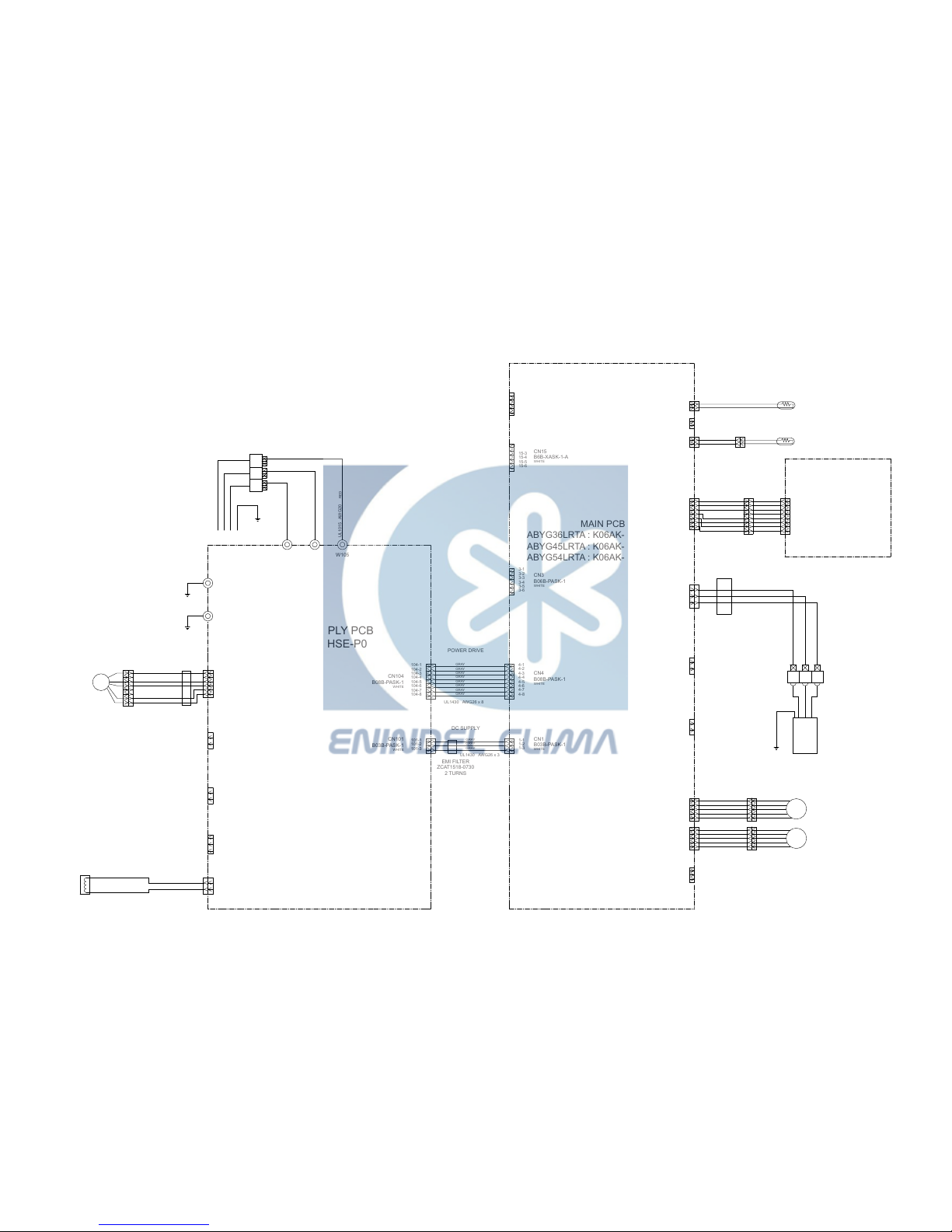
POWER DRIVE
CN4
B08B-PASK-1
WHITE
DC SUPPLY
CN1
B03B-PASK-1
WHITE
CN105
B5P6-VH-B
WHITE
DRAIN PUMP
CN106
B2P3-VH-B-E
BLUE
EX. OUT
EX. I N
CN103
B2B-XH-AM
WHITE
CN102
B3B-XH-AM
WHITE
CN108
B2P3-VH-B
WHITE
NORMAL COIL
RLEY41-22
22mH, 2.2A
F M
DC FAN MOTOR
E101
E102
W101 W102 W105
CN104
B08B-PASK-1
WHITE
CN101
B03B-PASK-1
WHITE
CN14
B03B-XAKK-1-A
BLACK
CN6
B02B-PAMK-1
GREEN
FRESH AIR
CN10
B02B-PAOK-1
ORANGE
LOUVER ( UP / DOWN )
LOUVER ( RIGHT / LEFT )
M
M
CN11
B05B-XASK-1-A
WHITE
CN12
B05B-XARK-1-A
RED
FLOAT SWITCH
CN9
B03B-XARK-1-A
RED
WIRED REMOTE CONTROL
( OPTION )
TERMINAL
123
EARTH WIRE
UL1430 AWG22 RED
UL1430 AWG22 WHITE
UL1430 AWG22 BLACK
UL1015
AWG16
GREEN
UL1015 AWG20 BLACK
UL1015 AWG20 WHITE
UL1015 AWG20 RED
UL1015
AWG16
GREEN
TERMINAL
3
1
2(N)
OUTDOOR UNIT
EMI FILTER
ZCAT1518-0730
2 TURNS
EMI FILTER
ZCAT1518-0730
2 TURNS
EMI FILTER
GTFC-25-15-12
2 TURNS
INDICATOR PCB
K04GN-1100HSE-D0
MAIN PCB
ABYG36LRTA : K06AK-1212HSE-C1
ABYG45LRTA : K06AK-1213HSE-C1
ABYG54LRTA : K06AK-121GHSE-C1
POWER SUPPLY PCB
K06AL-1105HSE-P0
CONTROL UNIT
ABYG36LRTA : EZ-0122DHSE
ABYG45LRTA : EZ-0122EHSE
ABYG54LRTA : EZ-01234HSE
INDOOR PCB
CIRCUIT DIAGRAM
2013.03.07 6
www.enindel.com
Page 8

5V
C29
0.1
<F>
R57
1.0k
<1/10W>
R59
10k
<1/10W>
C30
0.1
<F>
R58
1.0k
<1/10W>
R60
49.9k
<1/10W>
C34
0.1
<F>
R62
1.0k
<1/10W>
R61
49.9k
<1/10W>
CN9
B03B-XARK-1-A
FLOAT SWITCH
5V
R45
10k
<1/10W>
R46
1.0k
<1/10W>
C31
0.01
<F>
5V
5V
THERMISTOR ( ROOM TEMP. )
CN8
B02B-XASK-1-A
CN7
B02B-XAYK-1-A
THERMISTOR ( PIPE TEMP. )
CN5
B02B-XAKK-1-A
CN15
B06B-XASK-1-A
FLASH
CN13
B07B-PASK-1
I NDICATOR PCB
CN14
B03B-XAKK-1-A
WIRED REMOTE CONTROL
( OPTION )
5V
R68, R52
10k <1/10W> x 2
5V
R41
1.0k
<1/10W>
R43, R44
10k <1/10W>
x 2
R42
47
<1/10W>
C24
1000p
<R>
C23
0.01
<F>
C25
10/
50V
+
C26
0.01
<F>
12V
5V
5V
13.5V
13.5V
R47
390
<1/10W>
R35
1.0k
<1/10W>
R36
0R0
I C6-2
BA10393F
I C6-1
BA10393F
R55
10k
<1/10W>
12V
12V
D3
D1FS4A
D2
DAN217U
R54
15.4k
<1/10W>
R53
28k
<1/10W>
R48
10k
<1/10W>
I C4
uLN2003
BZ1
PKM13EPYH-4000-A0
CN11
B05B-XASK-1-A
CN12
B05B-XARK-1-A
LOUVER ( UP / DOWN )
LOUVER ( RIGHT / LEFT )
Q2
DTC124EKA
5V
I C7
S80842
R56
100k
<1/10W>
C27
0.1
<B>
C38
0.1
<B>
R69
10k
<1/10W>
R40
10k
<1/10W>
C13
0.1
<B>
I C5
S-93C66BD0 I
I C1
uPD78F0536
C36
0.47
<F>
JM5
0R0
C8 - C10
0.1 <F> x 3
5V
5V
R4 - R6
1.0k <1/10W> x 3
R1 - R3
10k <1/10W> x 3
JM1
JM2
JM3
C32
100/
6.3V
+
C33
0.1
<F>
C28
0.1
<F>
R19 - R22
1.0k <1/10W> x 4
5V
12V13.5V
5V
C3
0.01
<F>
+
D1
1SS355
I C2
NJM7805
+
C1
10/
50V
C2
10/
50V
I C8
NJM7812
D4
1SS355
5V
R15 - R18
10k <1/10W> x 4
R70
10k
<1/10W>
Q3
DTC124EKA
5V
5V
5V
C20 - C22
0.1 <F>
x 3
13.5V
R7 - R10
1.0k <1/10W> x 4
R11 - R14
10k <1/10W> x 4
SW1
CFS-0402MC
I C3
uPA2003
R29
390
<1/10W>
R28
10k
<1/10W>
C16
0.01
<F>
Q1
DTC124EKA
C15
0.01
<F>
C14
1000p
<R>
5V
C17
0.01
<F>
C18
0.01
<B>
R27
330
<1/10W>
R34
1.0k
<1/10W>
R33
10k
<1/10W>
R31
10k
<1/10W>
13.5V
13.5V
R25
1.0k
<1/10W>
R26
10k
<1/10W>
C35, C12, C11
1000p <R> x 3
C37
0.1
<F>
R67
1.0k
<1/10W>
5V
13.5V
R24, R23, R32
10k <1/10W> x 3
R63 - R65
1.0k <1/10W> x 3
R66
10k
<1/10W>
X1
8.00MHz
<FCR>
CN4
B08B-PASK-1
POWER DRIVE
CN3
B06B-PASK-1
TEST
CN2
B5P-SHF-1AA
CN1
B03B-PASK-1
DC SUPPLY
1
2
3
1
2
1
2
1
2
1
2
3
4
5
6
1
2
3
4
5
6
7
1
2
3
1
2
3
4
5
1
2
3
4
5
1
2
3
4
5
6
7
8
1
2
3
4
5
6
1
3
2
3
2
1
8
7
6
5
4
3
2
1
9
16
15
14
13
12
11
10
8
1
2
3
4
5
6
7
SK
O1
O2
O3
O4
O5
O6
O7
GND
I 1
I 2
I 3
I 4
I 5
I 6
I 7
SK
O1
O2
O3
O4
O5
O6
O7
GND
I 1
I 2
I 3
I 4
I 5
I 6
I 7
9
16
15
14
13
12
11
10
8
1
2
3
4
5
6
7
1
3
2
2134VDD
OUTNCGND
1
2
3
4
5
1
2
3
1
2
1
2
123IGO
IGO
1
2
3
CN6
B02B-PAMK-1
FRESH AIR
HEATER
CN10
B02B-PAOK-1
1
2
3
6
8
4
7
5
CS
SK
D I
NC
VCC
DO
NC
GND
NC
34
39
36
43
44
45
46
33
32
31
30
29
28
27
26
18
19
20
21
22
23
11
12
13
14
38
37
41
40
25
9
42
52
51
50
49
48
47
56
55
54
53
8
7
6
5
4
3
2
1
64
63
62
61
60
59
58
57
17
16
15
24
10
35AVREF
I C
RST*
P00
P01
P02
P03
P10
P11
P12
P13
P14
P15
P16
P17
P20
P21
P22
P23
P24
P25
P30
P31
P32
P33
XT1
XT2
X1
X2
AGND
GND0
GND1
P75
P74
P73
P72
P71
P70
P67
P66
P65
P64
P57
P56
P55
P54
P53
P52
P51
P50
P47
P46
P45
P44
P43
P42
P41
P40
P36
P35
P34
VDD1
VDD0
AVDD
3
1
2
3
1 2
+
1
2
3
-
7
6
5
+
-
SP PCB
C4
0.01
<F>
C5
1000p
<R>
C7
1000p
<R>
C19
0.1
<B>
R37
10k
<1/10W>
B Z
R50
10k
<1/10W>
INDOOR UNIT
MAIN PCB
ABYG36LRTA : K06AK-1212HSE-C1
ABYG45LRTA : K06AK-1213HSE-C1
ABYG54LRTA : K06AK-121GHSE-C1
2013.03.07 7
www.enindel.com
Page 9

340V
15V
C119
0.01
<KH>
15V
A
6
5
4
3
2
1
CN105
B5P-VH-B
DC FAN MOTOR
I C103
TLP621
<GB>
R114
4.7k
<1/10W>
R115
6.8k
<1/4W>
5V
15V
R116
1.0k
<1/4W>
I C104
TLP621
<GB>
R117
820
<1/4W>
C117
100/
25V
+
A
A
1
2
4
3
4
312
CN104
B08B-PASK-1
1
2
3
4
5
6
7
8
1
2
3
3
2
1
1
2
5V
L102
BLm18
<AG601>
L103
BLm18
<AG601>
I C101
TLP621
<GB>
R112
330
<1/10W>
C116
0.01
<B>
4
3 2
1
13.5V
CN103
B2B-XH-AM
CN102
B3B-XH-AM
5V 13.5V
C121
0.1
<F>
C120
0.1
<F>
CN101
B03B-PASK-1
CN106
B2P3-VH-B-E
5V
I C 1 0 5
H I 2 0 0 3 R 3
VA103
0.01
<F>
2
1
K102
G5NB-1A
13.5V
RC101
120/
0.2
3 2
4
1
DRAIN PUMP
K101
G5NB-1A
4
2
1
3
18 14 10 5
4 3
2 1
5
4
3
2 1
6
7
8
W105
RED
SERIAL
E102
GREEN
C118
0.01
<KH>
1 2
CN108
B2P3-VH-B
NORMAL COIL
D101
D3SB60
4
3
1
2
340V
R104
330k
<2W>
C109
220p
<B>
R105
75
<RS-2W>
Q101
2SC5354
3
2
1
1
2
3
Q102
2SC1815
R107
100
<1/10W>
R106
1.5
<RS-2W>
15V
D106
D1FL20U
A
C112
330/
25V
+
C111
100/
25V
D104
MTZJ5.1B
D109
MTZJ5.1B
R109
330
<1/4W>
+
R108
100
<1/2W>
D105
D1FL20U
D103
D1FL20U
C110 0.047
<ECQV>
D107
RD16
<B1>
R110
10k
<1/10W>
C115
0.01
<KH>
C114
0.01
<KH>
13.5V
D108
D2FL20U
C113
1000/
25V
T101
ZFT22B03-C
R111
10k
<1/10W>
+
12
10
2
3
5
6
7
8
C108
4700p
<FNS>
R103
62k
<RS-2W>
D102
1SR139-600
C107
270/
450V
+
C105
0.010
<LE>
C106
0.010
<LE>
C104
0.22
<R41>
LF101
ELF20N018A
1 2
4
3
C101
0.22
<LE>
VA102
470V
<TNR>
SA101
RA-362M
VA101
470V
<TNR>
FH101
FH102
F101
3.15A
250V
W101
BLACK
W102
WHITE
E101
GREEN
L
I C26-14
N
I C26-10
FC51FL x 2
L
I C26-14NI C26-10
L
I C26-14
N
I C26-10
EX. OUT
EX. I N
R113
330
<1/10W>
POWER DRIVE
DC SUPPLY
INDOOR UNIT
POWER SUPPLY PCB
K06AL-1105HSE-P0
2012.02.29 8
www.enindel.com
Page 10

5V
JM201
PHA201
P I C-37143TH5
2
1
3
VCC
OUT
GND
C202
10/
16V
+
C201
0.1
<F>
SW201
EVQPAG04K
D207 EMPG3863X GREEN
D206 EMAA3863X ORANGE
D205 EMPG3863X GREEN
R202
330
<1/4W>
R203
330
<1/4W>
R201
330
<1/4W>
CN201
08 / 08 JC / XMR
1430 L=300
1
2
3
4
5
6
7
8
BROWN
RED
ORANGE
YELLOW
WHITE
BLUE
PURPLE
GRAY
OPERATE
TIMER
LOUVER
LOUVER
5V
REMOTE SIGNAL
GND
MANUAL AUTO SWITCH
TO MAIN PCB
INDOOR UNIT
INDICATOR PCB
K04GN1100HSE-D0
2012.02.28 9
www.enindel.com
Page 11

REACTOR
L1 - L3
17mH 14A x 3
UL1015
AWG14
BLACK
UL1015
AWG14
BLACK
UL1015
AWG14
WHITE
UL1015
AWG14
WHITE
UL1015
AWG14
RED
UL1015
AWG14
RED
UL1015
AWG16
GREEN
EARTH
W6BW4
B
SERIAL
W3BW1
B
EARTH
UL1015
AWG16
GREEN
W5
B
EARTH
P200
P201
P202
W206
B
E
L1 I N
TM200
L2 I N
TM201
L3 I N
TM202
UL1015
AWG14
RED
UL1015
AWG14
WHITE
UL1015
AWG14
BLACK
UL1015
AWG16
GREEN
EMI FILTER
ZCAT2132-1130
2 TURNS
L1 OUT
TM203
L2 OUT
TM204
L3 OUT
TM205
UL1015
AWG20
BLACK
UL1015
AWG20
WHITE
UL1015
AWG20
RED
BLACK
BLUE
WHITE
RED
RED
WHITE
BLACK
1
2
3
4
5
6
1
2
3
4
5
6
1
2
3
4
5
6
1
2
1
2
1
2
3
1
2
1
2
1
2
1
2
3
1
2
3
1
2
3
1
2
3
1
2 3
4
5
6
7 8 9
1
2
1
2 3
4
5
6 1
2 3
4
5
6
7 8
1
2
1
3
5
1 2 3
1
2 3
4
5
6 1
2 3
4
5
6
7 8 9
UL1015
AWG12
ORANGE
UL1015
AWG12
ORANGE
UL1015
AWG12
PURPLE
UL1015
AWG20
BLACK
UL1015
AWG20
BLACK
UL3271
AWG12
RED
UL3271
AWG12
WHITE
UL3271
AWG12
BLACK
1
2 3
4
5
6
7 8
1
2 3
1
2
1
2 3
4
5
6
UL1015
AWG12
YELLOW
UL1015
AWG12
BLUE
UL1007 AWG24 BROWN
UL1007 AWG24 RED
UL1007 AWG24 ORANGE
UL1007 AWG24 YELLOW
UL1007 AWG24 GREEN
UL1007 AWG24 BROWN
UL1007 AWG24 RED
UL1007 AWG24 ORANGE
UL1007 AWG24 YELLOW
UL1007 AWG24 GREEN
UL1007 AWG24 BLUE
UL1015 AWG20 BLACK
UL1015 AWG20 BLUE
UL1015 AWG20 WHITE
UL1015
AWG14
RED
UL1015
AWG14
WHITE
UL1015
AWG14
BLACK
UL1007
AWG24
BLACK
UL1007
AWG24
WHITE
1
2 3
W700
B
P I N
W701
B
N I N
W702
B
P OUT
W703
B
N OUT
W302
B
L3 I N
W301
B
L2 I N
W300
B
L1 I N
TM504
DC+OUT
TM505
N OUT
W800
B
DC+I N
TM801
P OUT
TM804
U
TM805
V
TM806
W
TM802
P I N
TM803
N I N
CN803
1-1971032-2
RED
CN800
B06B-PASK
WHITE
FLASH
CN802
2-1871843-3
BLUE
CT OUT
CN801
1971032-8
WHITE
C M
COMPRESSOR
CN630
1971032-9
WHITE
CN650
B06B-PASK
WHITE
FLASH
TM300 TM500 TM301 TM501 TM302 TM502
L1 L2 L3
CT OUT
CN200
2-1871843-3
BLUE
F1
5A
250V
F2
3.15A
250V
F3
10A
250V
CN101
B3P5-VH-B
WHITE
AC I N
CN102
2-1747052-3
BLUE
REACTOR
CN9
1971032-9
WHITE
P.F.C. PCB
CN6
B06B-PASK-1
WHITE
FLASH
CN23
1-1971032-2
RED
THERMISTOR
( HEATSINK TEMP. )
CN7
1971032-8
WHITE
CN18
B03B-XASK-1-A
WHITE
EX. OUT
CN19
B03B-XAKK-1-A
BLACK
EX. I N
1
2 3
CN81
B6P-VH-B
WHITE
CN82
B6P-VH-B-C
BLACK
CN17
B6B-XARK-1-A
RED
CN103
1747052-1
WHITE
CN104
3-1747052-4
YELLOW
CN1
1871843-3
WHITE
CN21
2-1971032-2
BLUE
CN22
1971032-2
WHITE
CN20
3-1971032-2
YELLOW
CN25
1-1971032-3
RED
CN24
3-1971032-3
YELLOW
CN27
2-1971032-3
BLUE
CN26
1971032-3
WHITE
PRESSURE SENSOR
P S
F M
F M
E V
RED
BLACK
WHITE
YELLOW
BROWN
RED
BLACK
WHITE
YELLOW
BROWN
RED
BROWN
BLUE
ORANGE
YELLOW
WHITE
BLACK
BLACK
4-WAY VALVE COIL
EXPANSION VALVE COIL
DC FAN MOTOR 2
( LOWER )
DC FAN MOTOR 1
( UPPER )
THERMISTOR ( HEATSINK TEMP. )
L1
L2
L3
N
1
2
3
THERMISTOR ( PIPE M I D. TEMP. )
THERMISTOR ( PIPE TEMP. )
THERMISTOR ( DISCHARGE TEMP. )
THERMISTOR ( COMPRESSOR TEMP. )
THERMISTOR ( OUTDOOR TEMP. )
EMI FILTER
ZCAT1518-0730
2 TURNS
EMI FILTER
GRFC-10
1 TURN
EMI FILTER
GRFC-10
1 TURN
EMI FILTER
ZCAT1518-0730
2 TURNS
REACTOR
17mH 3A
EMI FILTER
GRFC-8
1 TURN
POWER SOURCE
AC380 - 415V
50Hz
I NDOOR UNIT
MAIN PCB
AOYG36LATT : K07AK-1200HUE-C1
AOYG45LATT : K07AK-1101HUE-C1
AOYG54LATT : K07AK-1102HUE-C1
CAPACITOR PCB
K07AP-0700HUE-P0
FILTER PCB
K07AQ-0700HUE-FL0
TRANSISTOR PCB
K11CA-1200HUE-TR1
ACTIVE FILTER PCB
K11BZ-1100HUE-AF0
INVERTER ASSEMBLY
AOYG36LATT : EZ-01222HUE
AOYG45LATT : EZ-0111WHUE
AOYG54LATT : EZ-0111YHUE
OUTDOOR PCB
CIRCUIT DIAGRAM
2013.03.07 10
www.enindel.com
Page 12

340V
+
15V-2
15V-2
R72, R73
1.0k<1/10W>
x 2
C75
1000p
<B>
C71
0.1
<B>
C72
0.1
<B>
12V
15V-3
Q70
DTC143EUA
R74
2.2k
<1/10W>
I C70
PS2561L-1-V
5V
A
2
3
1
4
3
2
1
2
3
1
C84
0.01
<B>
R88
1.0k
<1/10W>
5V
R87
10k
<1/10W>
D84
DAN217U
5V
15V
15V
3
1 2
R75
1.0k
<1/10W>
C73
0.01
<B>
R76
1.0k
<1/10W>
Q82
DTC143EUA
Q83
DTA143EUA
2
3
1
R85
33k
<1/10W>
D86
PTZ24B
C85
0.1
<B>
R86
22k
<1/10W>
C83
4.7/
50V
L81
BL02Rn1
15V
15V
C82
0.1
<B>
R82
22k
<1/10W>
+
C81
0.01
<B>
R84
1.0k
<1/10W>
D83
DAN217U
5V
5V
Q80
DTC143EUA
Q81
DTA143EUA
R83
10k
<1/10W>
C80
4.7/
50V
R81
33k
<1/10W>
L80
BL02Rn1
D85
PTZ24B
2
3
1
2
3
1
3
2
1
3
21
C151
0.1
<F>
5V
D151
DAN217U
R156
1.0k
<1/10W>
5V
D4
1SS355
+
C4
100/
16V
+
+
+
12V
15V
123
IGO
C14
0.1
<B>
R2
10k
<1/10W>
+
15V-2
15V-3
+
D
A
5V
+
+
C62, C63
0.1 <B>
x 2
C64
4.7/
50V
C66
4.7/
50V
6
3
MODE
8
59
45
61
42
43
16
17
18
19
20
21
22
23
24
25
26
27
46
47
48
49
60
58
57
54
53
52
50
51
10
62
1
2
64
44
63
4
5
36
9
7
15
14
3
1
2
13
12
11
35
56
55
40
41
39
37
38
34
33
32
31
30
29
28
P00
P01
P02
P03
P04
P05
P06
P07
P10
P11
P12
P13
P14
P15
P16
P17
P20
P21
P22
P23
P24
P25
P26
P27
P30
P31
P32
VREF
*RST
GND
GND
VCC
VCC
P33
P34
P35
P36
P37
P43
P44
P45
P46
P47
P50
P51
P52
P53
P54
P60
P61
P62
P63
P64
P65
P66
P67
P80
P81
P82
P83
P84
P85
P86
P_E2P_CS
P_EPV_D
P_E2P_SK
P_PR
P_E2P_D I
P_EPV_C
P_EPV_B
P_FM2_I N
P_SW_TR I AL
P_D I PSW3
P_D I PSW2
P_D I PSW1
P_EPV_A
P_PFC_SK
P_TSO2
P_TS I 2
P_PFC_SO
P_TSO
P_TS I
P_V2
P_LED1
P_LED2
P_LED3
P_SW_PUMP
P_SW_ENTR
P_SW_SEL
5V
MODE
RES
P_FM1_I N
P_PFC_S I
P_4WV_AC
P_SW_MODE
P_LED_COM1
P_FM2_PWM
P_LED_COM2
P_LED_COM3
P_SRV2
P_FM1_PWM
P_SRV1
P_DEMAND1
P_DEMAND2
P_S I
P_SO
P_POWER
P_AN_DC
P_AN_TH
P_AN_TD
P_AN_PS
P_AN_TT2
P_AN_TC
P_AN_TS
P_AN_TA
P_AN_TP
P_AN_TT
X1
8.00MHz
<CSTLS>
5V
I C63
S-93C66
R64
10k
<1/10W>
C61
0.1
<B>
R66
1.0k
<1/10W>
P_E2P_CS
P_E2P_SK
P_E2P_D I
1
2
3
7
5
6
4
8CS
SK
D I
NC
VCC
DO
TEST
GND
342
1NCGND
VDD
OUT
3
6
11
14
1
8
10
15
2
7
9
16
4
5
12
13
I 1
I 2
I 3
I 4
COM1
COM2
NC1
NC2
O1
O2
O3
O4
GND1
GND2
GND3
GND4
5V
R68
100k
<1/10W>
I C61
BU4842F
C60
0.1
<B>
12V
I C17
TD62064
1.5k <1/10W> x 4
R174
R173
R171
R172
C17
0.1
<B>
12V
P_EPV_D
P_EPV_C
P_EPV_A
P_EPV_B
R67
1.0k
<1/10W>
C67
0.01
<B>
R63
10k
<1/10W>
RESET
1
2
3
4
5
6
MODE
P_TS I
P_TSO
5V
12V
C92
0.1
<F>
R62, R61
10k <1/10W>
x 2
R60
4.7k
<1/10W>
C91
0.1
<F>
C95
1000p
<B>
15V-3
R92, R93
1.0k
<1/10W>
x 2
R94
2.2k
<1/10W>
I C90
PS2561L-1-V
5V
4
3
2
1
2
3
1
2
3
1
R95
1.0k
<1/10W>
C93
0.01
<F>
R96 1.0k
<1/10W>
Q91
DTC143EUA
Q90
DTC143EUA
D
P_PFC_S I
P_PFC_SK
P_PFC_SO
P_TSO2
P_TS I 2
1
2
3
4
5
6
7
8
9
1
2
3
4
5
6
7
8
1
2
3
4
5
6
1
2
3
4
5
6
340V
P_AN_DC
340V
340V
T1
I H024
7
6
5
4
3
2
1
16
15
14
13
12
11
10
9
4
2
1
8
7
6
5
D
C
M
S
S
S
S
I C2
TOP254
16
15
14
13
12
11
10
9
8
7
6
5
4
3
2
11C
2C
3C
4C
5C
6C
7C
COM
1B
2B
3B
4B
5B
6B
7B
E
3
2
4
1
3
2
4
1
3
21
1 2
4
3
4
3
2
1
3
2
4
1
1
2
3
4
2
3
4
1
3
4
2
1
2
3
1
2
3
1
4
3 2
1
342
1
5
6
7
8
4
3
2
1
3
2
1
3
1
2
3
2
1
3
1
2
3
2
1
3
1
2
2
3
1
18
14
10
5
4
3
2
1
8 7
6
5 432 1
P_S I
P_POWER
P_LED_COM3
P_LED_COM1
P_LED_COM2
P_SRV1
P_SW_TR I AL
P_SW_MODE
P_SW_SEL
P_SW_ENTR
P_SW_PUMP
P_D I PSW1
P_D I PSW3
P_D I PSW2
3
2
1
3
2
1
P_SRV2
P_DEMAND1
P_DEMAND2
+
12V
C106
0.22
<ECQU>
C104
0.01
<KH>
C105
0.01
<KH>
L101
RCV1904-050PF07
C101
0.22
<ECQU>
FH1 FH2
F1
5A
250V
VA1
470V
<TNR>
SA1
RA-302M
VA2
470V
<TNR>
FH5
FH6
F3
10A
250V
VA5
470V
<TNR>
SA2
RA-302M
VA4
470V
<TNR>
FH3
FH4
F2
3.15A
250V
VA3
470V
<TNR>
C107
0.22
<ECQU>
L102
SS11V05230
C112
0.22
<ECQU>
12V
Q31
DTA143EUA
Q32
DTA143EUA
Q33
DTA143EUA
12V
12V
Q34
DTC143EUA
Q35
DTC143EUA
Q36
DTC143EUA
5V
R65
10k
<1/10W>
C42 - C49
0.01 <B> x 8
5V
L20
BL02Rn1
P_AN_TS
P_AN_TT
P_AN_TT2
P_AN_TD
P_AN_TC
P_AN_TA
P_AN_TP
P_AN_TH
P_AN_PS
C161
0.1
<B>
C21
0.1
<B>
C25
0.1
<B>
C22
0.1
<B>
C24
0.1
<B>
C26
0.1
<B>
C27
0.1
<B>
C20
0.1
<B>
C23
0.1
<B>
R20
10k
<1/10W>
R23
10k
<1/10W>
R26
10k
<1/10W>
R27
10k
<1/10W>
R24
10k
<1/10W>
R22
10k
<1/10W>
R25
10k
<1/10W>
R21
10k
<1/10W>
R121 4.75k
<1/10W>
1%
R125 4.75k
<1/10W>
1%
R122 4.75k
<1/10W>
1%
R124 13k
<1/10W>
1%
R127 13k
<1/10W>
1%
R126 38.3k
<1/10W>
1%
R123 1.5k
<1/10W>
1%
R120 4.7k
<1/10W>
1%
5V
I C192
PS2561L-1-V
I C191
PS2561L-1-V
D192
1SS355
5V
12V
I C 1
R5F212AASNA79FP
C9
330/
35V
C7
330/
35V
5V
I C3 uLN2003
12V
C31
0.1
<B>
CR2
RE1202
CR1
RE1202
12V
12V
K1
G5NB-1A
K2
G5NB-1A
5V
5V
JM161
0R0
JM162
0R0
C162
0.1
<B>
D161
DAN217U
R163
10k
<1/10W>
R161
10k
<1/10W>
P_PR
P_SO
P_4WV_AC
P_V2
P_LED1
P_LED3
P_LED2
5V
NC
SW1
CES-0402MC
R142 - R149
10k <1/10W>
x 8
SW2 - SW6
KSM8WBTS
x 5
R45 - R49, R42 - R44
1.0k <1/10W> x 8
Q181
DTC143EUA
Q182
DTC143EUA
Q191
DTC143EUA
Q192
DTC143EUA
C191
0.1
<B>
C192
0.1
<B>
R191
10k
<1/10W>
R192
10k
<1/10W>
R194, R193
10k <1/10W> x 2
D31
SLR-32MC
GREEN
D32
SLR-325VC
RED
Q51
2SC2412K
<BQ>
C53
0.01
<B>
R56
1.0k
<1/10W>
R55
4.7k
<1/10W>
5V
5V
C51
0.01
<B>
R52
1.0k
<1/10W>
R50
47k
<1/10W>
R51
27k
<1/10W>
H Y I C 1
H U 2 0 01 R 3
1.0k <1/10W> x 6
R31
R32
R33
R35
R34
R36
R198
10k
<1/10W>
D191
1SS355
R197
10k
<1/10W>
JM191
0R0
1
2
3
4
1
2
3
4
D182
1SS355
I C182
PS2561L-1-V
R188 10k
<1/10W>
R189 10k
<1/10W>
I C181
PS2561L-1-V
JM181
0R0
D181
1SS355
R180, R182, R184, R186
R181, R183, R185, R187
1.0k <1/10W>
x 8
R196, R195
10k <1/10W>
x 2
R101
ZPR0RCH400
D101
LL25XB60
P I N 101 P I N 102
K101
G5NB-1A
15V
D5
1SS355
D10
UDZS8.2B
D6
1SS355
R11
47
<1/10W>
C6
47/
35V
+
R10
0R0
C12
0.1
<B>
R3 - R6
1.0M
<1/3W>
1%
x 4
R8
0R0
D8
UF4005
C5
2200p
<E>
R1
150k
<2W>
R7
10k
<1/10W>
R9
10k
<1/10W>
L151
BL02Rn1
R151 - R153
220k <1/3W> 1%
x 3
C113
500/
450V
R103 - R107
220k
<1/3W>
x 5
P_FM1=PWM
P_FM1_I N
P_FM2_PWM
P_FM2_I N
I C7
BA17805
C3
220/
16V
C13
0.1
<B>
C1
330/
35V
C2
470/
25V
2200p <B> x 6C32 C33
C34 C35
C36 C37
D1 D1FL20U
D2 D1FL20U
D3
D1FL20U
D7
D1FL20U
D9
D1FL20U
47 <1/10W> x 3
R12
R13
R14
R15
47
<1/10W>
R16
47
<1/10W>
CN102
2-1747052-3
BLUE
REACTOR
CN101
B3P5-VH-B
WHITE
AC I N
S
N
T
5
3
1
1
2
2
1
1
2
3
2
1
3
2
1
1
2
3
2
1
3
2
1
3
2
1
2
1
2
1
CN16
1871843-3
WHITE
PRESSURE SENSOR
CN104
3-1747052-4
YELLOW
CN103
1747052-1
WHITE
4-WAY VALVE
W4
SERIAL
RED
B
W6
EARTH
GREEN
B
W3
N
WHITE
B
W1
L
BLAXK
W5
EARTH
GREEN
B
CN21
2-1971032-2
BLUE
CN25
1-1971032-3
THERMISTOR ( PIPE TEMP. )
CN22
1971032-2
WHITE
CN24
3-1971032-3
YELLOW
THERMISTOR ( DISCHARGE TEMP. )
THERMISTOR ( PIPE-M ID. TEMP. )
CN27
2-1971032-3
BLUE
THERMISTOR ( COMPRESSOR TEMP. )
CN26
1971032-3
WHITE
THERMISTOR ( OUTDOOR TEMP. )
CN23
1-1971032-2
RED
THERMISTOR ( HEATSINK TEMP. )
CN20
3-1971032-2
YELLOW
CN19
B03B-XAKK-1-A
BLACK
EX. I N
CN18
B03B-XASK-1-A
WHITE
EX. OUT
CN81
B6P-VH-B
WHITE
DC FAN MOTOR 1
CN82
B6P-VH-B-C
BLACK
DC FAN MOTOR 2
CN7
1971032-8
WHITE
INVERTER PCB
CN9
1971032-9
WHITE
P.F.C. PCB
1
2
3
4
5
6
CN6
B06B-PASK-1
WHITE
FLASH
CN17
B6B-XARK-1-A
RED
EXPANSION VALVE COIL
C38, C39
1000p <B>
x 2
C40, C41
1000p <B>
x 2
1
2
C110
0.01
<KH>
C111
0.01
<KH>
PFC5000-0702F x 2 PFC5000-0702F x 2
PFC5000-0702F x 2
D33 - D39
SLR-325DC
ORANGE
x 7
OUTDOOR UNIT
MAIN PCB
AOYG36LATT : K07AK-1200HUE-C1
AOYG45LATT : K07AK-1101HUE-C1
AOYG54LATT : K07AK-1102HUE-C1
2013.03.07 11
www.enindel.com
Page 13

+
5V
C857
0.1
<F>
C858
4.7/
50V
5V
R863, R864
22k <1/10W>
1% x 2
5V
R860
100
<1/10W>
1%
+
15V
R857, R859
0R0 x 2
R843, R844
22k <1/10W>
1% x 2
R840
100
<1/10W>
1%
5V
5V
15V
5V
R862
10k
<1/10W>
1%
R861
10k
<1/10W>
1%
15V
5V
5V
C855
0.1
<F>
C856
4.7/
50V
I C840-3
BA2904F
VCC
G / V
8
4
3
2
1
1
2
3
+
-
I C840-1
BA2904F
2 1
3
R868
4.7k
<1/10W>
R867
1.0k
<1/10W>
C853
1000p
<B>
D851
DAN217U
R865, R866
22k <1/10W>
1% x 2
D850
DAN217U
I C840-2
BA2904F
-
7
+
6
5
2
3
1
D840
DAN217U
R845, R846
22k <1/10W>
1% x 2
R848
4.7k
<1/10W>
R847
1.0k
<1/10W>
D841
DAN217U
5V
C843
1000p
<B>
2
1
3
R841
10k
<1/10W>
1%
R842
10k
<1/10W>
1%
+
C810
4.7/
50V
5V
C802
4.7/
50V
+
C800, C801
0.1 <F>
x 2
C803, C804
0.1 <F>
x 2
I C800
uPD70F3713
I C801
BU4842F
C806
0.1
<F>
5V
R804
100k
<1/10W>
2
134
VDD
OUTNCGND
5
1
2
3
4
58
57
56
55
25
35
34
33
32
31
30
29
28
17
16
15
14
13
12
11
24
10
8
27
48
62
61
9
26
47
63
60
64
59
23
22
21
20
19
18
54
53
52
51
50
49
46
45
44
43
42
41
40
39
38
37
36
6
7
VCC
EVCC
EVCC
AVCC0
AVCC1
AVRF0
AVRF1
P11
P12
P13
P14
P16
P17
P20
P21
P22
P23
P24
P25
P26
P27
P30
P31
P32
P33
P40
P41
P42
P43
P44
X1
X2
RST*
AN I 00
AN I 01
AN I 02
AN I 03
AN I 10
AN I 11
AN I 12
AN I 13
FLMD0
PDL0
PDL1
PDL2
PDL3
PDL4
PDL5
PDL6
PDL7
P00
P01
P02
P03
P04
P05
P06
P10
REGC
GND
EGND
EGND
AGND0
AGND1
C809
0.1
<F>
C805
4.7/
50V
+
X800
2.5MHz
<CSTCC>
R815
10k
<1/10W>
5V
321
P_LED1
P_UP
P_UN
P_VP
P_VN
P_WP
P_WN
RXDA0
TXDA0
P_S I 1
P_SO1
HS
P_PR
P_TR
P_E2P_D I
P_E2P_SK
P_E2P_CS
P_JM2
P_JM1
FLMD0
P_DC2
P_M I
P_CT
P_I U
P_TH_HT
P_DC
P_I V
R802
4.7k
<1/10W>
R813
10k
<1/10W>
C807
0.01
<B>
R805
0R0
5V
R812
1.0k
<1/10W>
+
Q820
DTC143EUA
C828
0.01
<B>
3
1
2
R824
1.0k
<1/10W>
R823
1.0k
<1/10W>
I C822
PS2561L-1-V
5V
1
2 3
4
3
1
2
1
3
2
5V
R831
10k
<1/10W>
C831
0.1
<F>
D832
DAN217U
R838
10k
<1/10W>
C834
0.1
<F>
L830
BL02Rn1
5V
5V
5V
R852
10k
<1/10W>
R833
10k
<1/10W>
C833
0.1
<F>
R832
1.5k
<1/10W>
1%
R830
100k
<1/10W>
D830
DAN217U
5V
R820, R821
1.0k <1/10W> x 2
C827
1000p
<B>
R822
2.2k
<1/10W>
R814, R816
10k <1/10W>
x 2
P_CT
P_S I 1
P_SO1
RST_OUT
P_LED1
P_E2P_CS
P_E2P_SK
P_E2P_D I
P_DC2
P_PR
P_DC
2
1
3
1
2
3
7
8
4
6
5
CS
SK
D I
NC
VCC
DO
TEST
GND
3
1
2
Q835
DTC143EUA
5V
I C802
S-93C56B
R806
10k
<1/10W>
C808
0.1
<F>
R807
1.0k
<1/10W>
15V
D831
SLR-325
<RED>
R834
1.0k
<1/10W>
R835
1.0k
<1/10W>
5V
R896
10k
<1/10W>
C870
0.1
<F>
D870
DAN217U
2 1
3
R890 - R894
220k <1/3W>
1% x 5
L870
R895
5.6k
<1/10W>
1%
15V
R828, R829
0R0 x 2
12V
K880
G4AN-1A
4
1
3
2
1
2
3
3
1
2
D835
DAN217U
Q836
2SC2411K
R837
4.7k
<1/10W>
R836
4.7k
<1/10W>
5V
D860
DAN217U
R886
10k
<1/10W>
C860
0.1
<F>
R880 - R884
220k <1/3W>
1% x 5
L960
BL02Rn1
R885
5.6k
<1/10W>
1%
R926 - R931
1.0k <1/10W> x 6
R920 - R925
10k <1/10W> x 6
C920 - C925
1000p <B> x 6
P_UP
P_VP
P_WP
P_UN
P_VN
P_WN
P_I U
P_I V
P_M I
R990
4.7k
<1/10W>
5V
R800, R801
10k <1/10W> x 2
P_JM2
P_JM1
P_C I N
+
C963
4.7/
50V
15V
R969, R970
560 <1/10W>
x 2
R966
15k
<1/10W>
1%
C969
1000p
<B>
I C962
TL431A I
5V
C968
1000p
<B>
C
3
A
2
REF
1
1
3
2
+
-
I C961-1
BA2903F
5V
C941
1000p
<B>
R952
1.0k
<1/10W>
R951
4.7k
<1/10W>
R968
0R0
-
+
1
2
3
I C960-1
BA3472F
R964
1.8k
<1/10W>
1%
5V
C964
1000p
<B>
R960
1.8k
<1/10W>
1%
R962
15k
<1/10W>
1%
15V
C960
0.1
<F>
I C960-2
BA3472F
I C961-2
BA2903F
I C960-3
BA3472F
C962
0.1
<F>
I C961-3
BA2903F
15V
-
+
7
6
5
8
4
VCC
G / V
8
4
VCC
G / V
-
+
7
6
5
R851, R853, R855
10k <1/10W> x 3
12V
+
C822
100/
25V
C821
0.1
<F>
C820
0.1
<F>
+
C819
47/
35V
I C820
NJM7812
D820
1SS355
I C821
NJM7805
D821
1SS355
C826
100/
25V
C825
0.1
<F>
C824
0.1
<F>
+
C823
330/
35V
C818
0.1
<F>
123
I
O
G
123
I
O
G
P_VOT
RST_OUT
FLMD0
HS
RXDA0
TXDA0
P_TH_HT
P_C I N
P_VOT
R955
100
<1/4W>
P_TR
C942
0.01
<B>
R954
1.0k
<1/10W>
R953
10k
<1/10W>
C940
0.022
<F>
+
C904
220/
35V
C905
1.0
<B>
R932 - R937
330 <1/10W> x 6
I C900
PS22A76
D901
PTZ24B
1
3
4
6
7
9
10
12
13
14
15
16
18
27
28
29
25
26
23
21
22
24
19
40
39
38
37
36
35
34
UP
VP1
VUFB
VUFS
VP
VP1
VVFB
VVFS
WP
VP1
VPC
VWFB
VWFS
UN
VN
WN
CFO
FO
VOT
VN1
VNC
C I N
VSC
P
U
V
W
NU
NV
NW
R940 - R949
0.1 <1W> 1% x 10
D908
US1J
CT800, CT801
FC-1-X x 2
5V
C934
4.7/
50V
+
C932
0.1
<F>
C933
0.1
<F>
15V
L900
BL02Rn1
R910
39
<1/2W>
D910
STTH112
D911
STTH112
D912
STTH112
D913 - D915
PTZ24B
x 3
C910 - C912
220/35V
x 3
C913 - C915
1.0 <B>
x 3
R911 - R913
330k <1/10W>
x 3
C901 - C903
1.0 <B>
x 3
I C920-3
I C920-4
5 6 9 8
I C920-2
I C920-5
I C920-1
I C920-6
I C921-3
I C921-4
I C921-2
I C921-5
I C921-1
I C921-6
3 4 11 10
1 2 13 12
5 6 9 8
3 4 11 10
1 2 13 12
74HC14 x 12
3
434
2 1 2
1
1
2
3
4
5
6
7
8
1
2
3
1
2
1
2
3
4
5
6
CN803
1-1971032-2
( G I C2.0-2P )
RED
THERMISTOR ( HEATSINK TEMP. )
CN800
B06B-PASK-1-A
WHITE
FLASH
CT I N
CN802
2-1871843-3
( G I C2.5-3P )
BLUE
CN801
1971032-8
( G I C2.0-8P )
WHITE
MAIN PCB
W800
B
ORANGE
DC+ I N
DC +
P I N800
TM801
ORANGE
TM802
YELLOW
TM803
BLUE
P I N801
DC -
P I N
N I N
TM806
BLACK
TM805
WHITE
TM804
RED
U
V
W
P OUT
R900
10
<2.8W>
RGDU7M
R902
10
<7W>
RGGS7
R901
10
<7W>
RGGS7
SHUNT CURRENT DETECT
THIS FUNCTION IS DELETED
OVER CURRENT TRIP
PHASE V CURRENT DETECT
PHASE U CURRENT DETECT
EEPROM
LED
DC VOLTAGE DETECT 2
CT
MAIN PCB COM.
THERMISTOR
FLASH
DC VOLTAGE DETECT
I P M
MICON
OUTDOOR UNIT
TRANSISTOR PCB
K11CA-1200HUE-TR1
2012.03.06 12
C926 - C931
470p <B> x 6
www.enindel.com
Page 14

5V5V5V
C410
0.1
<F>
C412
0.1
<F>
C411
0.1
<F>
C454
100/
35V
+
D457
PTZ24B
15V
L450
BL02Rn1
R450
39
<1/2W>
R443
0R0
R444
0R0
C363
0.01
<B>
5V
R361 - R363
47k 1% x 3
R364
22k
C362
0.1
<F>
I C331-2
BA2902F
5V
-
R365
39k
1%
R366
22k
C364
0.1
<F>
+
6
5
7
-
+
2
3
1
1 3
2
-
+
13
12
14
-
+
9
10
8
-
+
13
12
14
-
+
2
3
1
-
+
6
5
7
-
+
2
3
1
3
1
2
231
-
+
6
5
7
2
3
1
15V
5V
5V
+
+
C302
4.7/
50V
C301
0.1
<F>
15V
C305
4.7/
50V
C300
0.1
<F>
D301
DAN217U
VR301
B2K
R304
10k
1%
R310
47k
1%
C307
100p
<CH>
I C300-1
BA2902F
R316
2.2k
C304
0.1
<F>
R307
10k
5V
R301
100
1%
5V
R334
22k
D331
RB751V
D334
RB751V
C334
0.1
<F>
R328
10k
5V
R346
47k
1%
R349
22k
C337
0.1
<F>
I C330-2
BA2902F
I C330-1
BA2902F
R331
47k
1%
R337
47k
1%
R340
47k
1%
R343
47k
1%
R352
47k
1%
R355
47k
1%
R330
47k
1%
R336
47k
1%
R339
47k
1%
R342
47k
1%
R351
47k
1%
R354
47k
1%
R345
47k
1%
R348
22k
C336
0.1
<F>
5V
15V
I C330-4
BA2902F
D330
RB751V
D333
RB751V
R327
10k
C333
0.1
<F>
R333
22k
5V
C330
0.1
<F>
I C330-3
BA2902F
-
+
9
10
8
-
+
13
12
14
R306
10k
C303
0.1
<F>
I C300-2
BA2902F
R315
2.2k
R309
47k
1%
C306
100p
<CH>
VR300
B2K
R303
10k
1%
R300
100
1%
15V
D300
DAN217U
1 2
3
CT301, CT300
FC-1-X x 2
3 4
2
1
3
2 1
4
R323
47k
1%
I C300-4
BA2902F
R326
2.2k
C320
0.1
<F>
5V
R335
10k
C335
0.1
<F>
R329
10k
D332
RB751V
D335
RB751V
5V
15V
I C331-4
BA2902F
C338
0.1
<F>
R350
22k
R347
47k
1%
R368
47k
I C331-3
BA2902F
C331
0.1
<F>
Q370
2SA1037AK
<Q>
R370
47
C365
0.1
R367
100k
I C331-1
BA2902F
C580
0.1
<F>
15V
C581 - C583
1000p <B>
x 3
C584
0.1
<B>
5V
R583
8.2k
1%
R584
2.2k
1%
15V 15V
R360
47k
1%
C360
0.01
<B>
C361
0.01
<B>
C600
0.1
<F>
5V
I C600-3
74HC00
10
9
8
5V
R601
10k
R603
1.0k
C602
100p
<CH>
C601
100p
<CH>
R602
1.0k
R600
10k
I C600-1
74HC00
R604
10k
C603
1000p
<B>
R605
1.0k
I C600-4
74HC00
5V
I C600-2
74HC00
R606
10k
5V
5
4
6
2
1
3
12
13
11
5V
R322
22k
R320, R321
47k 1% x 2
R332
47k
1%
R338
47k
1%
R341
47k
1%
R344
47k
1%
R353
47k
1%
R356
47k
1%
C380
0.1
<F>
C381
0.1
<F>
5V
R402
1.0k
I C380-1
BA2901F
I C380-1
BA2901F
I C381-4
BA2901F
R412, R415
10k x 2
C415, C418, C421
100p <CH> x 3
I C412-1
HC08
I C411-2
HC08
C414, C417, C420
100p <CH> x 3
R418
1.0k
R421, R424
1.0k x 2
R411, R414
10k x 2
I C412-2
HC08
R401
1.0k
I C381-2
BA2901F
R400
1.0k
I C381-3
BA2901F
5V
5V
5V
L380
BL02Rn1
C379
4.7/
50V
C377
4.7/
50V
+
C382
0.1
<F>
+
R386 10k
R389 3.9k 1%
R395
1.0k
1%
R392
100k
1%
I C380-4
BA2901F
-
+
10
11
13
-
+
8
9
14
-
+
6
7
1
-
+
-
+
-
+
8
9
6
7
4
5
2
1
14
-
+
-
+
4
5
2
10
11
13
-
+
4
5
2
-
+
6
7
1
8
9
14
-
+
5V
R440
1.0k
Q440 - Q445
DTC143EUA x 6
R441
2.2k
C440
1000p
<B>
2
3
1
2
3
1
2
3
1
2
3
1
2
3
1
2
3
1
2
1
3
4
5
6
8
11
9
10
12
13
I C412-4
HC08
I C411-3
HC08
I C412-3
HC08
I C410-1
HC08
I C410-4
HC08
1
2
3
4
5
6
12
13
11
9
10
8
1
2
5
4
3
6
9
10
12
13
8
11
I C411-1
HC08
I C411-4
HC08
I C410-2
HC08
I C410-3
HC08
R417
1.0k
R420, R423
1.0k x 2
C413, C416, C419
100p <CH>
x 3
R416
1.0k
R419, R422
1.0k x 2
10k x 2
R410 R413
C464
0.022
<F>
R454
100
<1/4W>
C463
0.1
<F>
C462
0.1
<F>
C461
0.1
<F>
C460
0.1
<F>
R445
0R0
R446
0R0
R447
0R0
R448
0R0
C389
0.1
<F>
R394
100k
1%
R397
1.0k
1%
R398, R399
10k 1% x 2
I C380-2
BA2901F
R393
100k
1%
R396
1.0k
1%
I C380-3
BA2901F
R387 10k
R390 3.9k 1%
C383
1000p
<B>
R380
1.0k
R383
4.7k
C384
1000p
<B>
R381
1.0k
R384
4.7k
C385
1000p
<B>
R382
1.0k
R385
4.7k
R388 10k
R391 3.9k 1%
I C580-3
BA2901F
I C580-2
BA2901F
I C580-1
BA2901F
R580 2.2k
R581 2.2k
R582 2.2k
REACTOR
L1 - L3
12A 18mH
x 3
TM300
TM301
TM302
TM500
TM501
TM502
R357
22k
R358
47k
C357
47/
35V
C358
0.1
<F>
+
D351
STTH112
D353
STTH112
D352
STTH112
R453 R452 R451 330k x 3
C453
C452
C451
47/35V x 3
R456 R455 R454
+
+
+
PTZ TE25 24B x 4
C459
C458
C457 0.1 <F> x 3
I C450
PS22A76
13467
9
10
12
13
14
15
16
18
27
28
292526
232122
24
19
40
39
38
37
363534
P
U
V
W
NU
NV
NW
UP
VP1
VUFB
VUFS
VP
VP1
VVFB
VVFSWPVP1
VPC
VWFB
VWFS
UNVNWN
CFO
FO
VOT
VN1
VNC
C I N
VSC
TM505
N OUT
TM504
DC+ OUT
L1 I N W300
L2 I N
L3 I N
W301
W302
P_I NTE_RESET / M13P
P_CURRCON_PWM / M34P
P_ERR_RESET / M05P
P_ERR_PFC / M04P
P_PLSCOUNT / M16P
P_AVECURR / M26P
P_ARMU_R / M06P
P_ARMD_R / M09P
P_ARMU_S / M07P
P_ARMD_S / M10P
P_ARMU_T / M08P
P_ARMD_T / M11P
PFC_ERROR
VDC_P
VAC_L3
VAC_L2
VAC_L1
Jump To Page2
Jump To Page2
From Filter PCB
OUTDOOR UNIT
ACTIVE FILTER PCB - 1
K-11BZ-1100HUE-AF0
2012.02.29 13
www.enindel.com
Page 15

5V
R590
10k
-
+
8
9
14
I C510-3
BA2901F
C591
1000p
<B>
C590
0.1
<F>
R591
2.2k
1%
R592
5.6k
1%
R550
22k
R551
47k
R543 47k 1%
C537 100p <CH>
R542
22k
5V
C536
0.1
<F>
I C530-4
BA2902F
R544
1.0k
+
C550
47/
35V
C551
0.1
<F>
-
+
14
13
12
-
+
-
+
-
+
-
+
6
5
7
3
1
2
2
3
1-
+
-
+
1 2
3
13
12
14
1
2
3
IGO
124
3
1
243
3421NC
GND
VDD
OUT
-
+
9
10
8
3
1
2
132
6
5
7
9
10
8
2
3
1
-
+
4
5
-
+
10
11
13
3
1
2
-
+
6
7
1
-
+
13
11
10
-
+
8
9
10
2 1
3
2 1
3
1
3
2
VDD
VSS
C
X1
X2
MD0
P123
P124
*RST
P40
P41
P120
48
47
46
45
44
43
42
41
40
39
38
37
13
14
15
16
17
18
19
20
21
22
23
24
P31
P30
P17
P16
P15
P14
P13
P12
P11
P10
AVDD
AVSS
2526272829303132333435
36
P27
P26
P25
P24
P23
P22
P21
P20
P130
P01
P00
P140
P32
P70
P71
P72
P73
P74
P75
P33
P63
P62
P61
P60
121110
987654321
P_FLMD0 / M43P
P_RESET / M40P
P_I NTE_RESET / M13P
P_LED1 / M36P
P_CURRCON_PWM / M34P
P_AD_VDC / M27P
P_AVECURR / M26P
P_PEAK_VAC / M25P
P_ERR_RESET / M05P
P_ERR_PFC / M04P
P_MODEL SW2 / M03P
P_MODEL SW1 / M02P
TEST JP / M01P
P_ARMU_R / M06P
P_ARMU_S / M07P
P_ARMU_T / M08P
P_ARMD_R / M09P
P_ARMD_S / M10P
P_ARMD_T / M11P
P_ZERO_S / M12P
P_ZERO_T / M13P
P_ZERO_R / M14P
P_PLSCOUNT / M16P
P_RXD / M18P
P_TXD / M19P
P_SDO / M20P
P_SD I / M21P
P_SDCLK / M22P
TEST JP / M01P
P_MODEL SW1 / M02P
P_MODEL SW2 / M03P
P_LED1 / M35P
2
3
1
Q670
DTC143EUA
15V
D670
SLR-325
RED
R670
1.0k
R671
1.0k
R660 - R662
10k x 3
5V
P_AD_VDC / M27P
R575
47k
C575
0.1
<F>
C562
0.1
<F>
5V
1
2
3
4
5
6
7
8
9
1
2
3
4
5
6
P_ZERO_T / M13P
P_ZERO_S / M12P
P_ZERO_R / M14P
P_PEAK_VAC / M25P
P_SDO / M20P
P_SDCLK / M22P
P_SD I / M21P
P_RESET / M40P
P_FLMD0 / M43P
P_RXD / M18P
P_TXD / M19P
15V
D470
DAN217U
R503 8.2k 1%
C476 1000p <B>
I C470-3
BA2902F
R506
2.2k
C473
1000p
<B>
R500
8.2k
1%
5V
D471
DAN217U
15V
R504 8.2k 1%
C477 1000p <B>
I C470-2
BA2902F
R501
8.2k
1%
5V
C474
1000p
<B>
R507
2.2k
D472
DAN217U
15V
R505 8.2k 1%
C478 1000p <B>
I C470-1
BA2902F
R502
8.2k
1%
5V
C475
1000p
<B>
R508
2.2k
15V
5V
5V
C470
0.1
<F>
C472
0.1
<F>
15V
D473
DAN217U
I C470-4
BA2902F
15V
I C630
NJM7805
D630
1SS355
+
C633
100/
25V
C632
0.1
<F>
C631
0.1
<F>
+
C630
330/
35V
C634
0.1
<F>
5V
I C635
PS2561L-1-V
I C636
PS2561L-1-V
Q640
DTC143EUA
R645
1.0k
5V
I C655
BU4842F
R652
10k
C645
0.1
<F>
R655
100k
R656
0R0
C646
0.01
<B>
R659
10k
R657
1.0k
R650, R651
10k x 2
R646
1.0k
C638
0.01
<B>
C637
0.01
<B>
R643, R644
1.0k x 2
R640, R638
1.0k x 2
5V
R639, R637
1.0k x 2
R636
2.2k
C636
1000p
<B>
R635
2.2k
C635
1000p
<B>
R495 - R499
220k <1/3W> 1% x 5
R480 - R484
220k <1/3W> 1% x 5
R490 - R494
220k <1/3W> 1% x 5
R475 - R479
220k <1/3W> 1% x 5
R485 - R489
220k <1/3W> 1% x 5
R470 - R474
220k <1/3W> 1% x 5
VAC_L3
VAC_L1
VAC_L2
R530, R536
47k 1% x 2
D530
RB751V
D533
RB751V
R527
10k
C533
0.1
<F>
I C530-2
BA2902F
R533
22k
5V
R531, R537
47k 1% x 2
D531
RB751V
D534
RB751V
R528
10k
C534
0.1
<F>
I C530-3
BA2902F
R534
22k
5V
R529
10k
C535
0.1
<F>
I C530-1
BA2902F
D532
RB751V
R535
22k
5V
D535
RB751V
R541
47k
1%
R532, R538
47k 1% x 2
R540
47k
1%
R539
47k
1%
15V
C530
0.1
<F>
15V
C510
0.1
<F>
I C510-2
BA2901F
R524
1.0k
5V
R521
1.0k
C521
1000p
<B>
C518
0.1
<F>
C515
1000p
<B>
R512
2.2k
R515
2.2k
5V
I C510-4
BA2901F
C514
1000p
<B>
C517
0.1
<F>
R511
2.2k
R514
2.2k
5V
C520
1000p
<B>
R523
1.0k
R520
1.0k
5V
I C510-1
BA2901F
C513
1000p
<B>
C516
0.1
<F>
R510
2.2k
R513
2.2k
5V
C519
1000p
<B>
R522
1.0k
R519
1.0k
5V
5V
+
C612
1.0
<F>
X610
8.00MHz
<CSTS>
C610
0.1
<F>
C613
4.7/
50V
5V
R594
8.2k
1%
R595
2.2k
1%
C593
0.1
<F>
I C580-4
BA2901F
C592
1000p
<B>
R593
10k
R572
1.0k
D561
DAN217U
I C300-3
BA2902F
R571 5.6k 1%
C561 1000p <B>
15V
C560
1000p
<B>
R570
5.6k
1%
R564, R563, R562, R561, R560
22k <1/3W> 1% x 5
R569, R568, R567, R566, R565
22k <1/3W> 1% x 5
5V
D560
DAN217U
15V
PFC_ERROR
VDC_P
CN630
1971032-9
( G I C2.0-9P )
WHITE
CN650
B06B-PASK
WHITE
Jump To Page1
Jump To Page1
I C610
uPD78F0514
C611
0.1
<F>
5V
TO MAIN PCB
FLASH
OUTDOOR UNIT
ACTIVE FILTER PCB - 2
K11BZ-1100HUE-AF0
2012.02.29 14
www.enindel.com
Page 16

CT200
FC-1-X
C221
220/
16V
+
R203
470
<1/4W>
VR200
B200
D201
D203
D202D200
1SS133 x 4
L200
RC3V3812-009PF05
12A 0.9mH
L201
RC3V3812-009PF05
12A 0.9mH
C218 - C220
1.0 <ECQUL>
x 3
C206 - C208
0.022 <ECQ-UY>
x 3
C200 - C202
1.0 <ECQUL>
x 3
R200 - R202
1.0M <1/2W>
x 3
SA200
RA-362M
VA203
470V
<TNR>
P202
<NSHV4>
15A
FH204 FH205
P201
<NSHV4>
15A
FH202 FH203
FH200 FH201
P200
<NSHV4>
15A
VA201
820V
<TNR>
VA200
820V
<TNR>
VA202
820V
<TNR>
TM203
TM204
TM205
L3 OUT
BLACK
L2 OUT
WHITE
L1 OUT
RED
5
6
3
4
1
2
5
6
3
4
1
2
L1 I N
RED
TM200
L2 I N
WHITE
TM201
L3 I N
BLACK
TM202
W206
E
GREEN
CN200
2-1871843-3
( G I C2.5-3P )
BLUE
CT OUT
1
2
3
1
2
3
3
2
4
1
3 Phase
380 - 415V
50Hz
H-0017-2 x 2
H-0017-2 x 2
H-0017-2 x 2
2012.02.29 15
OUTDOOR UNIT
FILTER PCB
K07AQ-0700HUE-FL0
www.enindel.com
Page 17

C703
660/
450V
+
C702
660/
450V
+
C700
660/
450V
+
C701
660/
450V
+
R703
68K
<RS-5W>
R702
68K
<RS-5W>
R701
68K
<RS-5W>
R700
68K
<RS-5W>
W700
P I N
ORANGE
PURPLE
N I N
W701
W702
P OUT
YELLOW
W703
N OUT
BLUE
2012.02.29 16
OUTDOOR UNIT
CAPACITOR PCB
K07AP-0700HUE-P0
www.enindel.com
Page 18

If you use a wireless remote control, the lamp
on the photo detector unit will output error codes
by way of blinking patterns.
If you use a wired type remote control, error
codes will appear on the remote control display.
See the lamp blinking patterns and error codes
in the table. An error display is displayed only
during running.
Indoor unit
Wired
remote
control
INDOOR UNIT
and WIRED REMOTE CONTROL
ERROR DETECTION
Description
OPERATION
lamp
(green)
TIMER
lamp
(orange)
ECONOMY
lamp
(green)
(1) (1)
Serial communication error
(1) (2)
Wired remote control communication error
(1)
(5)
Check run unfinished
(2)
(1)
R.C. address or Refrigerant circuit address setting error
[Simultaneous Multi]
(2) (2)
Indoor unit capacity error
(2) (3)
Combination error
(2)
(4)
Connection R.C. address error
(indoor secondary unit) [Simultaneous Multi]
•
Connection R.C. address error
(indoor unit or branch unit) [Flexible Multi]
•
(2)
(7)
Primary unit, secondary unit set-up error
Power supply interruption error
[Simultaneous Multi]
(3)
(2)
Indoor unit PCB model
information error
(3) (5)
Manual auto switch error
(4) (1)
Room temp. sensor error
(4) (2)
Indoor unit Heat Ex. Middle temp. sensor error
(5)
(1)
Indoor unit fan motor error
(5)
(3)
Drain pump error
(5) (7)
Damper error
(5) (15)
Indoor unit error
(6)
(2)
Outdoor unit main PCB model information
error or communication error
(6) (3)
Inverter error
(6)
(4)
Active filter error, PFC circuit error
(6) (5)
Trip terminal L error
(6)
(10)
Display PCB microcomputers
communication error
: 0.5s on / 0.5s off
: 0.1s on / 0.1s off
( ) : Number of flashing
This is possible only on a wired remote control.
If an error occurs, the following display will be shown.
(“Er” will appear in the set room temperature display.)
2012.07.25 17
(3)
(1)
Indoor unit
Wired
remote
control
Description
OPERATION
lamp
(green)
TIMER
lamp
(orange)
ECONOMY
lamp
(green)
(7)
(1)
Discharge temp. sensor error
(7) (2)
Compressor temp. sensor error
(7) (3)
Outdoor unit Heat Ex. liquid temp. sensor error
(7) (4)
Outdoor temp. sensor error
(7)
(5)
Suction Gas temp. sensor error
(7) (6)
2-way valve temp. sensor error•
3-way valve temp. sensor error•
(7) (7)
Heat sink temp. sensor error
(8) (2)
Sub-cool Heat Ex. gas inlet temp. sensor error•
Sub-cool Heat Ex. gas outlet temp.sensor error•
(8) (3)
Liquid pipe temp. sensor error
(8) (4)
Current sensor error
(8) (6)
Discharge pressure sensor error•
Suction pressure sensor error•
High pressure switch error•
(9) (4)
Trip detection
(9) (5)
Compressor rotor position detection error
(permanent stop)
(9) (7)
Outdoor unit fan motor 1 error
(9) (9)
4-way valve error
Coil (expansion valve) error
Outdoor unit fan motor 2 error
(10) (1)
Discharge temp. error
(10) (3)
Compressor temp. error
(10) (4)
High pressure error
(10) (5)
Low pressure error
(13) (2)
Branch boxes error
[Flexible Multi]
(9) (8)
(9) (10)
Remote control
.
Indoor unit display
Troubleshooting at the display is possible either
on the wired or wireless remote control.
OPERATION Lamp (green)
TIMER Lamp (orange)
ECONOMY Lamp (green)
Error code
Unit number of indoor unit
EX. Self-diagnosis
www.enindel.com
Page 19

TEST RUN
OUTDOOR UNIT
CAUTION
Always turn on the power 6 hours prior to the start of the
operation in order to protect the compressor.
1. Check items before performing the test run
Make sure to perform the test run.
Before performing the test run, be sure to check the
following points.
(1) Is gas leaking?
Check connection of each pipe (flare connection part,
brazing part).
(2) Is a breaker installed to the power cable of the outdoor unit ?
(3) Has each cable been securely connected to the terminal
according to the specifications ?
(4) Are the 3-way valves (gas pipes and liquid pipes) of the
outdoor units open?
(5) Has the power been supplied to the unit for at least 6 hours ?
(6) Has the necessary local setting been done ?
(7) Check insulation resistance of 1 M or more using a
500V mega tester.
If no problems are found with the above items, perform the
test run according to “Test run method”.
If any problems are found, immediately resolve the
2012.04.26 18
problem and re-check the items.
2. Test run method
CAUTION
If the test run is performed for 1 outdoor unit in a group
control system installation, the test run will also be
performed for the other units. Therefore, make sure that
all of the units have been installed before starting a test
run.
(Group control system installation described in “SPECIAL
INSTALLATION METHODS” in the installation manual of
the indoor unit.)
Operate [ENTER] (TEST RUN) switch on the display
board by the following procedure.
LED display
part
Operation mode
Upper : HEAT
Lower : COOL
[ ENTER ] ( TEST RUN ) switch
2.1. Operating procedures for the test run
(1) Check the 3-way valves (both at the liquid side and gas
side) are opened.
(2) Set the operation mode to “COOL” or “HEAT”.
POWER
MODE
ERROR
TEST
RUN
PUMP
DOWN
LOW NOISE PEAK CUT
(L1) (L2) (L3) (L4) (L5) (L6) (L7)
In the first test run, be sure to set the operation mode to
“COOL”.
The operation mode cannot be switched between “COOL”
and “HEAT” during the test run. To switch the operation
mode between “COOL” and “HEAT”, stop the test run,
switch the operation mode, and then start the test run
again.
(3) Press [ENTER] (TEST RUN) switch for more than
3 seconds.
POWER
MODE
ERROR
TEST
RUN
PUMP
DOWN
LOW NOISEPEAK CUT
(L1) (L2) (L3) (L4) (L5) (L6) (L7)
“TEST RUN” LED will light on.
If the compressor is operating at starting the test run, the
compressor will stop and, after a while, the test run will
start.
Either of the above "LOW NOISE" or "PEAK CUT" will light
on during the test run if local setting function is selected.
(4) Confirm operating status.
(5) Press [ENTER] (TEST RUN) switch again.
POWER
MODE
ERROR
TEST
RUN
PUMP
DOWN
LOW NOISE PEAK CUT
(L1) (L2) (L3) (L4) (L5) (L6) (L7)
“TEST RUN” LED lights off, and TEST RUN stops.
Test run will finish after about 60 minutes automatically.
At the same time, “TEST RUN” LED will light off.
Test run may be stopped before operating for
60 minutes if an error occurs after a starting test run.
www.enindel.com
Page 20

Error code check table
Display when an error occurs
ERROR
TEST
RUN
PUMP
DOWN
LOW NOISE PEAK CUT
POWER
MODE
(L1) (L2) (L3) (L4) (L5) (L6) (L7)
Blinks
(Hi-speed)
Check that the ERROR LED blinks,
and then short-press the [ENTER] switch once.
The number of blinks of the LED indicates the type of error.
POWER
ERROR
TEST
RUN
PUMP
DOWN
LOW NOISE PEAK CUT
Description
MODE
(L1) (L2) (L3) (L4) (L5) (L6) (L7)
(2) (1) (1)
Serial forward transmission error immediately after operation
(2) (1) (1)
Serial forward transmission error during operation
(2) (2) (2)
Indoor unit capacity error
(2) (5) (15)
Indoor unit error
(2) (6) (1)
Over voltage
(2) (6) (1)
Power supply frequency error
(2) (6) (2)
Outdoor unit PCB model information error
(2) (6) (2)
PFC communication error
(2) (6) (3)
Inverter error
(2) (6) (4)
PFC AD detection error
(2) (6) (4)
PFC hardware error
(2) (6) (5)
IPM error (Trip terminal L error)
(2) (6) (8)
Rush current limiting resister temp rise protection
(2) (7) (1)
Discharge temp. sensor error
(2) (7) (2)
Compressor temp. sensor error
(2) (7) (3)
Heat Ex. middle temp. sensor error
(2) (7) (3)
Outdoor unit Heat Ex. liquid temp. sensor error
(2) (7) (4)
Outdoor temp. sensor error
(2) (7) (7)
Heat sink temp. sensor error
(2) (7) (7)
PFC heat sink temp. sensor error
(2) (8) (4)
Current sensor 1 error (stoppage permanently)
(2) (8) (6)
High pressure switch 1 error
(2) (8) (6)
Pressure sensor error
(2) (9) (4)
Trip detection (stoppage permanently)
(2) (9) (5)
Compressor motor control error (stoppage permanently)
(2) (9) (5)
Compressor motor loss of synchronization (stoppage permanently)
(2) (9) (7)
Outdoor unit fan motor 1 error (Duty error)
(2) (9) (8)
Outdoor unit fan motor 2 error (Duty error)
(2) (9) (9)
4-way valve error
(2) (10) (1)
Discharge temp. 1 error (stoppage permanently)
(2) (10) (3)
Compressor 1 temp. error (stoppage permanently)
(2) (10) (5)
Low pressure error
Display mode : ON
: OFF
: Blink (0.5s ON / 0.5s OFF)
( ) : Number of flashing
OUTDOOR UNIT
ERROR CODE DISPLAY
2012.07.25
19
www.enindel.com
Page 21

1. Preparation for pump down
Confirm that the power is off,
and then open the service panel.
2. Pump down procedure
(1) Check the 3-way valves (both at the liquid side and gas
side) are opened.
(2) Turn the power on.
POWER
MODE
ERROR
TEST
RUN
PUMP
DOWN
LOW NOISE PEAK CUT
(L1) (L2) (L3) (L4) (L5) (L6) (L7)
(3) Press [PUMP DOWN] switch for 3 seconds or more after
3 minutes after power on.
ERROR
TEST
RUN
PUMP
DOWN
LOW NOISEPEAK CUT
POWER
MODE
(L1) (L2) (L3) (L4) (L5) (L6) (L7)
LED display lights on as shown in the above figure, and
the fans and the compressor start operating.
If the [PUMP DOWN] switch is pressed while the
compressor is operating, the compressor will stop, then
start again in about 3 minutes.
(4) LED display will change as shown below about 3
minutes after the compressor starts. Fully close the
3-way valve on the liquid pipe side at this stage.
ERROR
TEST
RUN
PUMP
DOWN
LOW NOISEPEAK CUT
POWER
MODE
(L1) (L2) (L3) (L4) (L5) (L6) (L7)
If the valve on the liquid pipe side is not closed, the
pump down cannot be performed.
(5) When LED display changes as shown in the below
figure, close the 3-way valve on the gas pipe side tightly.
ERROR
TEST
RUN
PUMP
DOWN
LOW NOISEPEAK CUT
POWER
MODE
(L1) (L2) (L3) (L4) (L5) (L6) (L7)
If the valve on the gas pipe side is not closed, refrigerant
may flow into the piping after the compressor stops
Step (5)
Closing direction
Step (4)
Hexagon wrench
Liquid pipe
Gas pipe
Closing direction
(6) LED display changes after 1 minute as shown in the
figure below
ERROR
TEST
RUN
PUMP
DOWN
LOW NOISEPEAK CUT
POWER
MODE
(L1) (L2) (L3) (L4) (L5) (L6) (L7)
Fans and compressor stop automatically.
If the pump down is successfully completed (the above
LED display is shown), the outdoor unit remains stopped
until the power is turned off.
(7) Turn the power off.
ERROR
TEST
RUN
PUMP
DOWN
LOW NOISEPEAK CUT
POWER
MODE
(L1) (L2) (L3) (L4) (L5) (L6) (L7)
PUMP DOWN is completed.
(Note)
To stop pump down, press the [PUMP DOWN] switch
again.
To start the pump down again after the compressor is
automatically stopped due to an error, turn the power
off and open the 3-way valves. Wait 3 minutes, turn the
power on and start the pump down again.
When starting the operation after completion of the pump
down, turn the power off, and then open the 3-way valves.
Wait 3 minutes, turn the power on and perform a test run
in the “COOL” operation mode.
PUMP DOWN (Refrigerant collecting operation)
OUTDOOR UNIT
Perform the following procedures to collect the
refrigerant when moving the indoor unit or outdoor unit
2012.04.26 20
WARNING
Never touch electrical components such as the terminal
blocks or reactor except the switch on the display board.
It may cause a serious accident such as electric shock.
CAUTION
Perform the pump down operation before disconnecting
any refrigerant pipe or electric cable.
Collect refrigerant from the service port or the 3-way
valve if pump down cannot be performed.
In case of a group control system installation, do not turn
the power off pump down is completed in all outdoor
units.
(Group control system installation described in “SPECIAL
INSTALLATION METHODS” in the installation manual of
the indoor unit.)
Operate [PUMP DOWN] switch on the display board in
the manner described below.
LED display part
PUMP DOWN
switch
Service port
Service port cap
Service hose
Reactors
Charging port
Charging port cap
3-way valve
Service hose
Terminal blocks
www.enindel.com
Page 22

10
2
4
11
13
6
8
9
7
3
1
5
INDOOR UNIT
2012.04.09 21
PARTS
12
13
14
15
11
10 Air Filter 9359739012
1 Kit (Base Sub Assy) 9371360010
11 Front Panel 9359734017
9 Intake Grille 9359738015
15 Badge 9359735175
5 Cover (Decoration) R 9359744016
6 Cover (Decoration) L 9359745013
12 Indicator PCB 9705891050
2 Panel Left Sub Assy 9360427014
3 Kit (Panel Right Assy) 9371361017
4 Top Cover 9359737018
7 Kit (Side Cover R) 9371364025
8 Kit (Side Cover L) 9371365022
14 Receiver Cover 9359714002
13 PCB Holder 9359736011
Ref. Description Part number
www.enindel.com
Page 23

22
21
INDOOR UNIT
Drain pan, Flap
2012.04.09
3
22
23
2
26
27
25
24
3
23
28
21
Evaporator Sub Assy (36, 45)
9360428264
Drain Pan Sub Assy 936042903222
23 Flap Assy 9359731016
-- Drain Cap 9358746004
2 Panel Left Sub Assy 9360427014
3 Kit (Panel Right Assy) 9371361017
25 Sector Gear 9359729006
24 Flap Spring 9359730002
26 Pinion Gear 9359728009
27 Motor Base 9359727002
21 Evaporator Sub Assy (54) 9360428301
-- Pipe Thermistor 9900022020
28 Step Motor V 9900362010
Ref.
Description Part number
22
www.enindel.com
Page 24

38
34
35
36
31
31
32
38
33
37
INDOOR UNIT
Fan motor
2012.04.09
35 Sirocco Fan Assy 9359701002
33 Casing 9359704003
38 Bearing B Assy 9357921006
31 Fan Motor Assy 9603167011
32 Rubber 9385102002
37 Shaft 9359707004
36 Joint Assy 9378038011
34
Kit (Cover Casing) Sub Assy
9371367019
Ref. Description Part number
23
www.enindel.com
Page 25

INDOOR UNIT
Louver Base Sub Assy
2012.04.09 24
42 Louver 9359719014
41 Louver Base Sub Assy 9360432049
47 Motor Rod 9359723004
46 Louver Link 9359726005
43
kit (Louver Base) Sub Assy
9371369013
45 Louver Spring 9359720003
49 Louver Stopper 9359724001
48 Louver Rod 9359725008
44 Step Motor H 9900297015
50 Louver Insulation R 9359721000
51 Louver Insulation L 9359722007
Ref. Description Part number
48
47
49
46
45
43
42
41
50
44
51
www.enindel.com
Page 26

INDOOR UNIT
Control unit
2013.03.07 25
Ref. Description Part number
66 Room Thermistor 9703299025
61 Main PCB (36) 9709245385
61 Main PCB (45) 9709245292
61 Main PCB (54) 9709245521
67 Remote Control 9379219037
68
Remote Control Holder
9305642045
63 Terminal 3P 9703345012
64 Terminal 3P 9306489045
65 Reactor Assy 9707457018
62 Power Supply PCB 9707398342
66
68
67
65
64
63
61
62
www.enindel.com
Page 27

1 Top Panel Sub Assy 9374417032
Ref. Description Parts number
2012.07.25
6 Right Panel Sub Assy 9374416219
14 Protective Net 9375381042
13 Thermo Holder 9375211011
4 Emblem Rear 9351355005
5 Pipe Cover Front 9378861015
3 Sevice Panel Sub Assy 9374415076
2 Front Panel Sub Assy 9374414130
PARTS
OUTDOOR UNIT
3
5
6
2
1
4
14
10
9
7
8
12
11
10
Ref. Description Parts number
9
11
12
8
7
Propeller Fan Assy
Motor, DC Brushless
Condenser A Sub Assy
Condenser B Sub Assy
Reactor Assy
Base Assy
9366378020
9602843046
9374420261
9374422081
9900641016
9374166220
13
26
www.enindel.com
Page 28

26
29
24
25
23
22
21
28
27
30
4-way Valve Assy
Expansion Valve Assy
21
Ref. Description Parts number
22
25
24
29
26
27
30
23
28
2012.03.16
Expansion Valve Coil
Expansion Valve Assy
4-way Valve Assy
Solenoid
OUTDOOR UNIT
Accumulator Assy
3-way Valve Assy
3-way Valve Assy
Compressor Sub Assy
Strainer Assy
Sensor
9900190057
9370947182
9374425273
9970113024
9375250096
9379079006
9379077002
9374423286
9372524039
9900505011
27
www.enindel.com
Page 29

42
(yellow)
(white)
(connector
: blue)
(red)
(red)
2
0
0
6
5
0
(red)
(white)
41
40
43
44
32
34
36
31
35
33
37
39
38
32
31
33
34
35
36
37
2013.03.07
9707609011
9707627091
9709008010
9707608014
9709010020
9900481018
9900428082
Filter PCB
Main PCB (36)
31 9707627077Main PCB (45)
31 9707627084Main PCB (54)
Ref.
OUTDOOR UNIT
Parts numberDescription
Active Filter PCB
Capacitor PCB
Transistor PCB
Reactor Assy
Terminal
39
38
40
41
42
43
44
Discharge Thermistor
Compressor Thermistor
Thermistor (Heat Exchanger Mid)
Thermistor (Heat Exchanger Out)
Outdoor Thermistor
Heatsink Thermistor (Inverter)
Heatsink Thermistor (PFC)
9900515003
9900516000
9900513009
9900514006
9900517007
9900518011
9900518028
28
www.enindel.com
Page 30

Name and Shape Q'ty Part numberApplication
Name and Shape Q'ty Part numberApplication
INDOOR UNIT
Special nut A
(large flange)
Special nut B
(small flange)
Installation
template
Adhesive type 70 x 230
1
Drain hose
insulation
For fixing the drain hose
L 280 mm
1
VT wire
For indoor side pipe joint
(gas pipe)
2
1
Coupler heat
insulator
(large)
For indoor side pipe joint
(liquid pipe)
4
Coupler heat
insulator
(small)
For fixing the coupler heat
insulator
Large
4
Small
4
Cable tie
For installing indoor unit
For positioning the indoor unit
4
For installing indoor unit
1
312300787605
9360464002
313806350303
9378173569
9374714025
9378173521
9301501001
313005446653
313005446759
9360022004
For connecting the piping
1
1
2
Auxiliary
pipe assembly
OUTDOOR UNIT
For drain piping work
For drain piping work
Drain pipe
Drain cap
9303029015
313166024302
2
For drain piping workOne-touch bush 9378779013
ACCESSORIES
2012.04.29 29
0700019036
0600185541
9305642045
9379219037
1
1
2
2
For air conditioner operation
For installing remote control
on the wall
For remote control
For mounting the remote
control holder
Remote
control
holder
Remote
control
Battery
Tapping screw
www.enindel.com
Page 31

Name and Shape Model name Use
Wired remote control UTY-RNNYM Unit control is performed by
wired remote control
Simple remote control UTY-RSNYM For air conditioner operation
Drain pump unit
UTR-DPB24T
Round flange
OPTIONAL PARTS
2012.07.25 30
UTD-RF204 To take fresh air
External connect kit
External connect set
UTY-XWZXZ2
UTD-ECS5A
For control input/output port
External connect kit UTY-XWZX For control input/output port
Use to connect with various
peripheral devices and air
conditioner PC board.
(Set of 6)
( x 1 ) ( x 2 )
( x 1 ) ( x 2 )
INPUT / OUTPUT
www.enindel.com
Page 32

1204G4041
www.enindel.com
 Loading...