

Page 1
SPLIT TYPE
AIR CONDITIONER
CEILING TYPE (50Hz)
Indoor unit Outdoor unit
ABYG45LRTA AOYG45LETL
CONTENTS
SPECIFICATIONS . . . . . . . . . . . . . . . . . . .
1
DIMENSIONS. . . . . . . . . . . . . . . . . . . . . . .
2
REFRIGERANT SYSTEM DIAGRAM . . . .
3
CIRCUIT DIAGRAM. . . . . . . . . . . . . . . . . .
4
ERROR DETECTION. . . . . . . . . . . . . . . .
5
INDOOR PCB CIRCUIT DIAGRAM . . . . . .
. . . .
9
OUTDOOR PCB CIRCUIT DIAGRAM
15
PARTS (INDOOR UNIT) . . . . . . . . . . . . .
19
PARTS (OUTDOOR UNIT) . . . . . . . . . . .
24
ACCESSORIES. . . . . . . . . . . . . . . . . . . .
27
www.enindel.com
Page 2
H x W x DOUTDOOR UNIT
DIMENSIONS
Shipping / NetOUTDOOR UNIT
WEIGHT
POWER SOURCE
Cooling
RUNNING
CURRENT
Heating
INPUT WATTS
Cooling
Heating
E.E.R.
C.O.P.
Cooling
Heating
Cooling
Heating
MOISTURE REMOVAL
AIR CIRCULATION
OUTDOOR
FAN MOTOR
INDOOR UNIT, Discrimination
High
INDOOR UNIT
Medium
Low
Upper fan
Lower fan
OUTDOOR UNIT, Discrimination
OUTDOOR UNIT
Cooling
TYPE
Cooling & Heating
INDOOR UNIT
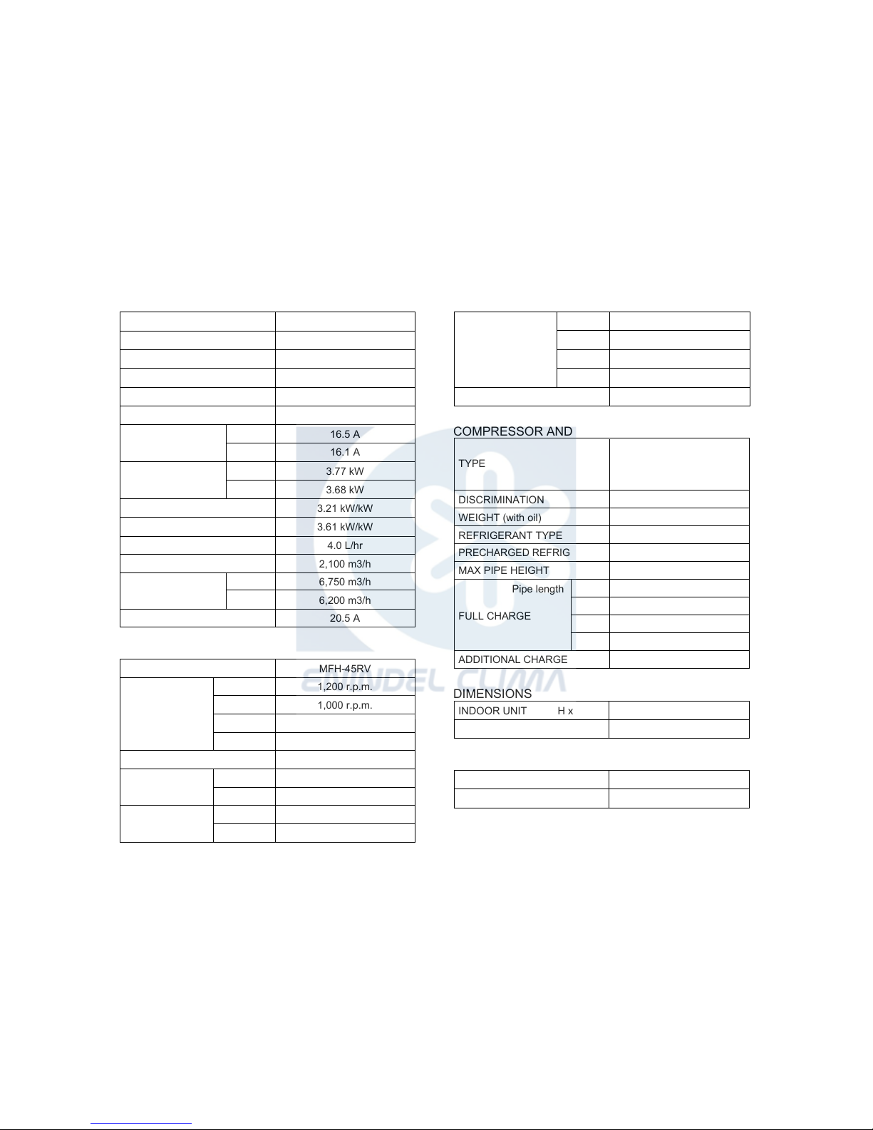
ABYG45LRTA
OUTDOOR UNIT
AOYG45LETL
COOLING CAPACITY
HEATING CAPACITY
INDOOR UNIT H x W x D
240 x 1,665 x 700 mm
1,290 x 900 x 330 mm
INDOOR UNIT
Shipping / Net
58 kg / 46 kg
94 kg / 86 kg
16.5 A
16.1 A
3.77 kW
3.68 kW
3.21 kW/kW
3.61 kW/kW
4.0 L/hr
6,200 m3/h
MAXIMUM CURRENT
20.5 A
AIR CIRCULATION INDOOR
2,100 m3/h
6,750 m3/h
230 V, 50 Hz, single phase
MFH-45RV
1,200 r.p.m.
1,000 r.p.m.
830 r.p.m.
Quiet
680 r.p.m.
MFE-45VVT
800 r.p.m.
850 r.p.m.
Upper fan
Lower fan
OUTDOOR UNIT
Heating
750 r.p.m.
780 r.p.m.
12.1 kW
13.3 kW
ELECTRICAL DATA
TYPE
DISCRIMINATION
WEIGHT (with oil)
REFRIGERANT TYPE
R410A
Hermetic type, Inverter,
6 poles, 3 phase,
DC motor, Twin Rotary
N-TF30HD1A
15.4 kg
PRECHARGED REFRIGERANT
3,350 g
COMPRESSOR AND REFRIGERANT
2013.02.22 1
SPECIFICATIONS
MAX PIPE HEIGHT
30 m
Pipe length
20 m
3,350 g
FULL CHARGE
30 m
3,750 g
40 m
4,150 g
50 m
4,550 g
ADDITIONAL CHARGE
40 g/m
NOISE LEVEL
High
INDOOR UNIT
Medium
Low
49 dB
45 dB
39 dB
Quiet
34 dB
OUTDOOR UNIT 55 dB
www.enindel.com
Page 3
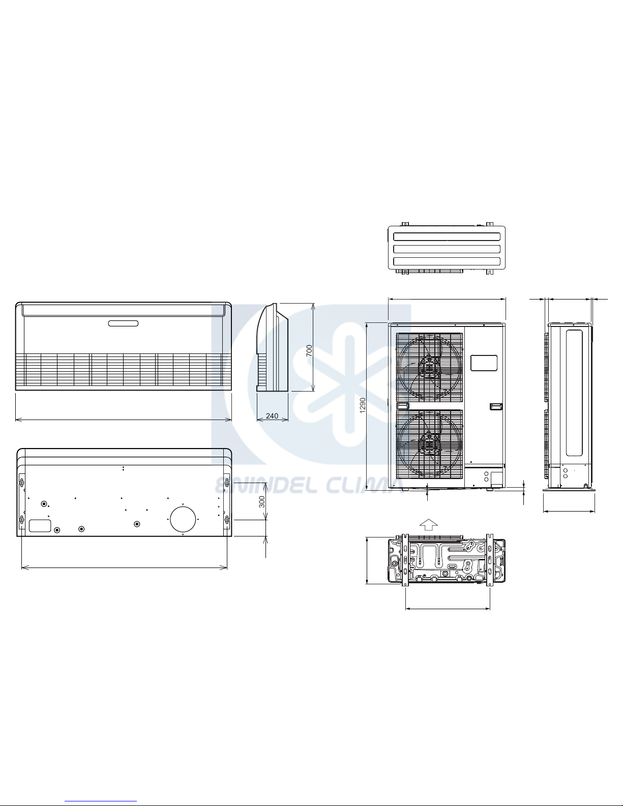
OUTDOOR UNIT
2013.02.22 2
DIMENSIONS
(Unit : mm)
INDOOR UNIT
31 12330
900
9
21
1290
650
400
370
air flow
1,660 240
700
1,600
130 300
www.enindel.com
Page 4

REFRIGERANT SYSTEM DIAGRAM
2013.02.15
Thermistor (Compressor)
Compressor
4-way
Valve
Pressure
Check Valve
Pressure
Sensor
Muffler
Check
Valve
Strainer Strainer
Expansion
Valve
Muffler
3-way Valve
3-way Valve
Accumulator
High Pressure
Switch
Refrigerant Pipe
9.52mm (3/8")
Refrigerant Pipe
15.88mm (5/8")
Thermistor (Discharge)
Thermistor (Room)
Heat
Exchanger
Heat
Exchanger
Thermistor (Pipe)
Thermistor (Heat Exchanger Med)
Thermistor (Heat Exchanger Out)
Thermistor (Outdoor)
Cool
Refrigerant direction
Heat
3
OUTDOOR UNIT INDOOR UNIT
www.enindel.com
Page 5
INDOOR UNIT
OUTDOOR UNIT
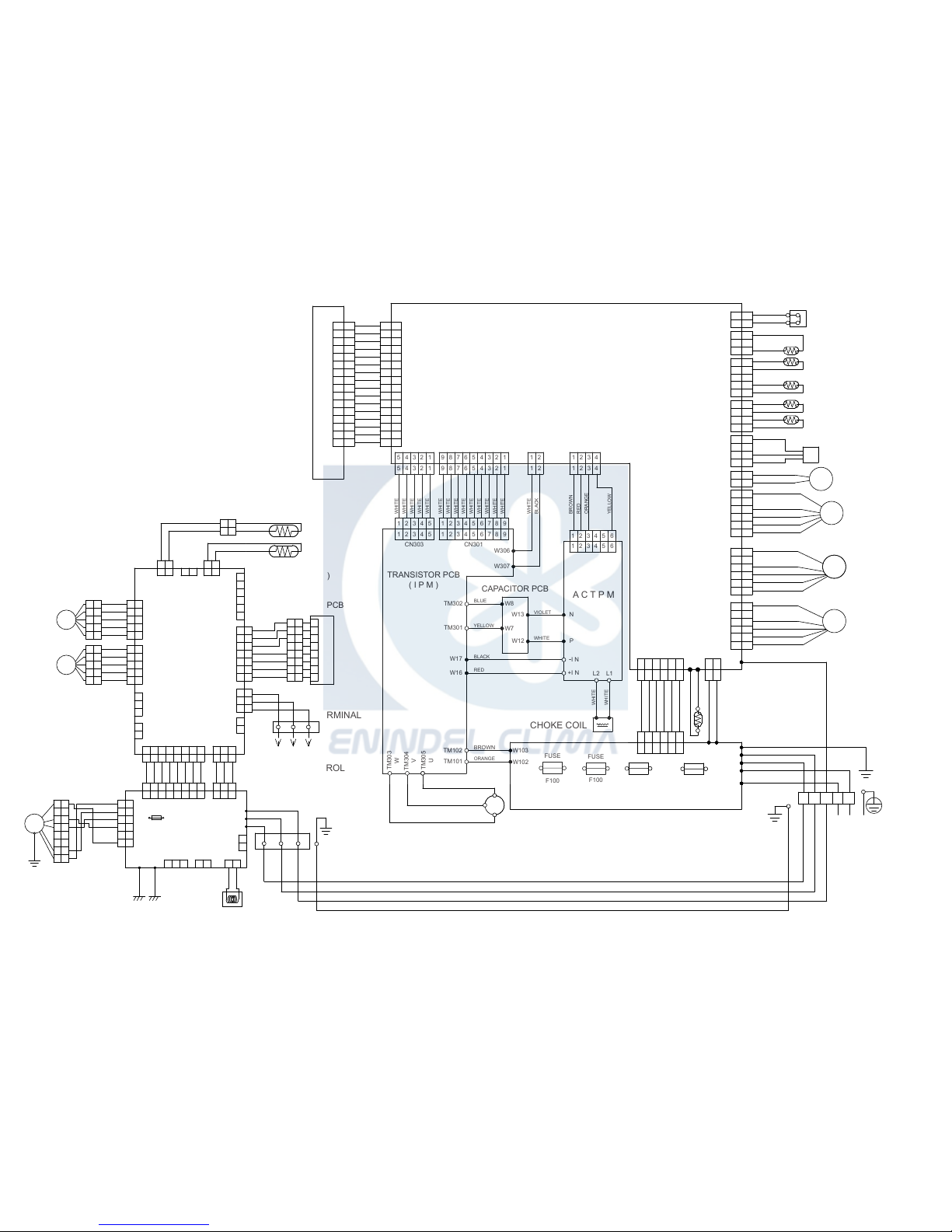
CIRCUIT DIAGRAM
2013.01.22 4
W106
W113
W104
W101
W100
W107
W108
W103
W102
CN101
CN2 CN1
W201
W111
W112
CN800
CN802
CN111
CN6
CN91
CN62
CN63
CN61
CN101
L2 L1
N
P
-I N
+I N
W8
W7
W13
W12
W306
W307
CN301CN303
TM302
TM301
W17
W16
TM102
TM101
TM303
W
TM304
V
TM305
U
CN400CN21CN20CN320
CN40
CN401
1
2
3
4
5
6
7
8
9
10
11
12
13
14
15
16
1
2
3
4
5
6
7
8
9
10
11
12
13
14
15
16
1
2
3
4
5
6
7
8
9
10
11
12
13
14
15
16
1
2
3
4
5
6
7
8
9
10
11
12
13
14
15
16
121
2
1
2
3
1
2
3
1
2
3
4
5
1
2
3
4
5
1
2
3
4
1
2
3
4
1
2
3
4
1
2
3
4
121
2
1
2
3
4
5
6
1
2
3
4
5
6
1
2
3
4
5
6
1
2
3
4
5
6
1
2
3
4
5
6
1
2
3
4
5
6
1
23456789
1
23456789
1
2345
1
2345
9
87654321
9
8765432154321
54321
654321
654321
2
1
2
1
4321
4321
654321
2
1
654321
2
1
654321
654321
ORANGE
ORANGE
RED
WHITE
WHITE
WHITE
WHITE
WHITE
WHITE
BLACK
WHITE
WHITE
YELLOW
ORANGE
RED
BROWN
WHITE
BLACK
WHITE
WHITE
WHITE
WHITE
WHITE
WHITE
WHITE
WHITE
WHITE
WHITE
WHITE
WHITE
WHITE
WHITE
RED
WHITE
WHITE
WHITE
WHITE
WHITE
WHITE
WHITE
WHITE
WHITE
WHITE
WHITE
WHITE
WHITE
WHITE
WHITE
BLUE
YELLOW
BLACK
RED
VIOLET
WHITE
BROWN
ORANGE
GREEN
WHITE
BLACK
WHITE
BLACK
RED
BROWN
YELLOW
WHITE
BLACK
RED
BROWN
YELLOW
WHITE
BLACK
RED
RED
BLUE
ORANGE
YELLOW
WHITE
BLACL
BLACK
BLACK
WHITE
RED
BLACK
BLACK
BLACK
BLACK
BLACK
BLACK
BLACK
BLACK
BLACK
BLACK
RED
RED
FUSE
F103
AC250V 30A
TERMINAL
1 2 3
L N
POWER SOURCE
CHOKE COIL
COMPRESSOR
CM
R
S
T
RED
WHITE
BLACK
HIGH PRESSURE SWITCH
THERMISTOR ( OUTDOOR TEMP. )
THERMISTOR ( PIPE TEMP. )
THERMISTOR ( PIPE - MID. TEMP. )
THERMISTOR ( DICHARGE TEMP. )
THERMISTOR
( COMP. SHELL TEMP. )
PS
4-WAY VALVE
EXPANSION VALVE
4WV
PMV
FM
FM
FAN MOTOR
( UPPER )
FAN MOTOR
( LOWER )
MAIN PCB
A C T P M
FUSE
F101
AC250V 10A
FUSE
F100
AC250V 3.15A
FUSE
F100
AC250V 10A
FILTER PCB
TRANSISTOR PCB
( I P M )
CAPACITOR PCB
INDICATOR PCB
1
2
3
121
2
E101 E102
CN102 CN103
CN108
COIL
EX. I N EX. OUT
( OPTION )
WHITE
WHITE
GREEN
GREEN
TERMINAL
1 2 3
1
2
W105
W102
W101
CN106
F101
3.15A
250V
CN105
CN104 CN101
POWER
SUPPLY
PCB
FM
FAN MOTOR
1
2
3
4
5
6
7
8
1
2
3
4
5
6
7
8
BROWN
YELLOW
WHITE
BLACK
RED
1
2
3
4
5
6
1
2
3
4
5
6
123 4 5 6 7 8
1
2
3 4 5 6 7 8
1
2
3 4 5 6 7 8
123 4 5 6 7 8
123
1
2
3
1
2
3
123
GRAY
GRAY
GRAY
GRAY
GRAY
GRAY
GRAY
GRAY
GRAY
GRAY
GRAY
GREEN /
YELLOW
1
2
3
4
5
6
1
2
3
4
5
6
7
CN3
CN13
CN14
CN6
TERMINAL
1 2 3
1
2
3
4
5
6
7
1
2
3
1
2
1
2
3
1
2
3
4
5
6
7
1
2
3
4
5
6
7
1
2
3
4
5
6
7
8 8 8
RED
WHITE
BLACK
BROWN
RED
ORANGE
WHITE
BLUE
PURPLE
GRAY
1
2
3
4
5
1
2
3
4
5
1
2
3
4
5
1
2
3
4
5
1
2
3
4
5
1
2
3
4
5
1
2
3
4
5
1
2
3
4
5
1
2
3
1
2
1
2
1
2
121
2
1
2
1
2
1
2
CN4 CN1
THERMISTOR
( ROOM TEMP. )
THERMISTOR
( PIPE TEMP. )
CN10
CN9
CN11
CN12
CN5
CN7
CN8
GRAY
GRAY
BLACK
BLACK
BLACK
BLACK
BROWN
RED
ORANGE
YELLOW
WHITE
BROWN
RED
ORANGE
YELLOW
WHITE
M
M
TO WIRED
REMOTE CONTROL
MAIN PCB
INDICATOR PCB
LOUVER
( RIGHT / LEFT )
LOUVER
( UP / DOWN )
www.enindel.com
Page 6

UL1430 AWG28 x 7
WHITE
BLUE
PURPLE
GRAY
ORANGE
RED
BROWN
1
2
3
4
5
6
7
8
1
2
3
4
5
6
7
8
WHITE
BLUE
PURPLE
GRAY
ORANGE
RED
BROWN
YELLOW
UL1430 AWG28 x 5
UL1430 AWG28 x 5
BROWN
RED
ORANGE
YELLOW
WHITE
BROWN
RED
ORANGE
YELLOW
WHITE
BROWN
RED
ORANGE
YELLOW
WHITE
BROWN
RED
ORANGE
YELLOW
WHITE
BLACK
BLACK
GRAY
GRAY
BLACK
BLACK
UL1430 AWG26 x 8
GRAY
GRAY
GRAY
GRAY
GRAY
GRAY
GRAY
GRAY
GRAY
GRAY
GRAY
UL1430 AWG26 x 3
UL1015 AWG20 x 2
UL1015 AWG22 x 5
RED
BLACK
WHITE
YELLOW
BROWN
4-1
4-2
4-3
4-4
4-5
4-6
4-7
4-8
1-1
1-2
1-3
3-1
3-2
3-3
3-4
3-5
3-6
15-1
15-2
15-3
15-4
15-5
15-6
2-1
2-2
2-3
2-4
2-5
1
2
3
4
5
6
7
8
104-1
104-2
104-3
104-4
104-5
104-6
104-7
104-8
101-1
101-2
101-3
13-1
13-2
13-3
13-4
13-5
13-6
13-7
8-1
8-2
7-1
7-2
5-1
5-2
201-1
201-2
201-3
201-4
201-5
201-6
201-7
201-8
105-6
105-5
105-4
105-3
105-2
105-1
106-1
106-2
102-1
102-2
102-3
103-1
103-2
108-1
108-2
11-1
11-2
11-3
11-4
11-5
12-1
12-2
12-3
12-4
12-5
9-1
9-2
9-3
14-1
14-2
14-3
6-1
6-2
10-1
10-2
CN201
JC25-08HG
WHITE
CN13
B07B-PASK-1
WHITE
THERMISTOR ( PIPE TEMP. )
THERMISTOR ( ROOM TEMP. )
CN5
B02B-XAKK-1-A
BLACK
CN7
B02B-XAYK-1-A
YELLOW
CN8
B02B-XASK-1-A
WHITE
CN2
B5P-SHF-1AA
WHITE
CN15
B6B-XASK-1-A
WHITE
CN3
B06B-PASK-1
WHITE
POWER DRIVE
CN4
B08B-PASK-1
WHITE
DC SUPPLY
CN1
B03B-PASK-1
WHITE
CN105
B5P6-VH-B
WHITE
DRAIN PUMP
CN106
B2P3-VH-B-E
BLUE
EX. OUT
EX. IN
CN103
B2B-XH-AM
WHITE
CN102
B3B-XH-AM
WHITE
CN108
B2P3-VH-B
WHITE
NORMAL COIL
RLEY41-22
22mH, 2.2A
F M
DC FAN MOTOR
E101
E102
W101 W102 W105
CN104
B08B-PASK-1
WHITE
CN101
B03B-PASK-1
WHITE
CN14
B03B-XAKK-1-A
BLACK
CN6
B02B-PAMK-1
GREEN
FRESH AIR
CN10
B02B-PAOK-1
ORANGE
LOUVER ( UP / DOWN )
LOUVER ( RIGHT / LEFT )
M
M
CN11
B05B-XASK-1-A
WHITE
CN12
B05B-XARK-1-A
RED
FLOAT SWITCH
CN9
B03B-XARK-1-A
RED
WIRED REMOTE CONTROL
( OPTION )
TERMINAL
123
EARTH WIRE
UL1430 AWG22 RED
UL1430 AWG22 WHITE
UL1430 AWG22 BLACK
UL1015
AWG16
GREEN
UL1015 AWG20 BLACK
UL1015 AWG20 WHITE
UL1015 AWG20 RED
UL1015
AWG16
GREEN
TERMINAL
3
1
2(N)
OUTDOOR UNIT
EMI FILTER
ZCAT1518-0730
2 TURNS
EMI FILTER
ZCAT1518-0730
2 TURNS
EMI FILTER
GTFC-25-15-12
2 TURNS
INDICATOR PCB
K04GN-1100HSE-D0
MAIN PCB
K06AK-1213HSE-C1
POWER SUPPLY PCB
K06AL-1105HSE-P0
CONTROL UNIT
EZ-0122EHSE
INDOOR PCB
CIRCUIT DIAGRAM
2013.01.22 5
www.enindel.com
Page 7

5V
C29
0.1
<F>
R57
1.0k
<1/10W>
R59
10k
<1/10W>
C30
0.1
<F>
R58
1.0k
<1/10W>
R60
49.9k
<1/10W>
C34
0.1
<F>
R62
1.0k
<1/10W>
R61
49.9k
<1/10W>
CN9
B03B-XARK-1-A
FLOAT SWITCH
5V
R45
10k
<1/10W>
R46
1.0k
<1/10W>
C31
0.01
<F>
5V
5V
THERMISTOR ( ROOM TEMP. )
CN8
B02B-XASK-1-A
CN7
B02B-XAYK-1-A
THERMISTOR ( PIPE TEMP. )
CN5
B02B-XAKK-1-A
CN15
B06B-XASK-1-A
( FLASH )
CN13
B07B-PASK-1
( INDICATOR PCB )
CN14
B03B-XAKK-1-A
WIRED REMOTE CONTROL
5V
R68, R52
10k <1/10W> x 2
5V
R41
1.0k
<1/10W>
R43, R44
10k <1/10W>
x 2
R42
47
<1/10W>
C24
1000p
<R>
C23
0.01
<F>
C25
10/
50V
+
C26
0.01
<F>
12V
5V
5V
13.5V
13.5V
R47
390
<1/10W>
R35
1.0k
<1/10W>
R36
0R0
I C6-2
BA10393F
I C6-1
BA10393F
R55
10k
<1/10W>
12V
12V
D3
D1FS4A
D2
DAN217U
R54
15.4k
<1/10W>
R53
28k
<1/10W>
R48
10k
<1/10W>
I C4
uLN2003
BZ1
PKM13EPYH-4000-A0
CN11
B05B-XASK-1-A
CN12
B05B-XARK-1-A
LOUVER ( UP / DOWN )
LOUVER ( RIGHT / LEFT )
Q2
DTC124EKA
5V
I C7
S80842
R56
100k
<1/10W>
C27
0.1
<B>
C38
0.1
<B>
R69
10k
<1/10W>
R40
10k
<1/10W>
C13
0.1
<B>
I C5
S-93C66BD0 I
I C1
uPD78F0536
C36
0.47
<F>
JM5
0R0
C8 - C10
0.1 <F> x 3
5V
5V
R4 - R6
1.0k <1/10W> x 3
R1 - R3
10k <1/10W> x 3
JM1
JM2
JM3
C32
100/
6.3V
+
C33
0.1
<F>
C28
0.1
<F>
R19 - R22
1.0k <1/10W> x 4
5V
12V13.5V
5V
C3
0.01
<F>
+
D1
1SS355
I C2
NJM7805
+
C1
10/
50V
C2
10/
50V
I C8
NJM7812
D4
1SS355
5V
R15 - R18
10k <1/10W> x 4
R70
10k
<1/10W>
Q3
DTC124EKA
5V
5V
5V
C20 - C22
0.1 <F>
x 3
13.5V
R7 - R10
1.0k <1/10W> x 4
R11 - R14
10k <1/10W> x 4
SW1
CFS-0402MC
I C3
uPA2003
R29
390
<1/10W>
R28
10k
<1/10W>
C16
0.01
<F>
Q1
DTC124EKA
C15
0.01
<F>
C14
1000p
<R>
5V
C17
0.01
<F>
C18
0.01
<B>
R27
330
<1/10W>
R34
1.0k
<1/10W>
R33
10k
<1/10W>
R31
10k
<1/10W>
13.5V
13.5V
R25
1.0k
<1/10W>
R26
10k
<1/10W>
C35, C12, C11
1000p <R> x 3
C37
0.1
<F>
R67
1.0k
<1/10W>
5V
13.5V
R24, R23, R32
10k <1/10W> x 3
R63 - R65
1.0k <1/10W> x 3
R66
10k
<1/10W>
X1
8.00MHz
<FCR>
CN4
B08B-PASK-1
POWER DRIVE
CN3
B06B-PASK-1
( TEST )
CN2
B5P-SHF-1AA
CN1
B03B-PASK-1
DC SUPPLY
1
2
3
1
2
1
2
1
2
1
2
3
4
5
6
1
2
3
4
5
6
7
1
2
3
1
2
3
4
5
1
2
3
4
5
1
2
3
4
5
6
7
8
1
2
3
4
5
6
1
3
2
3
2
1
8
7
6
5
4
3
2
1
9
16
15
14
13
12
11
10
8
1
2
3
4
5
6
7
SK
O1
O2
O3
O4
O5
O6
O7
GND
I 1
I 2
I 3
I 4
I 5
I 6
I 7
SK
O1
O2
O3
O4
O5
O6
O7
GND
I 1
I 2
I 3
I 4
I 5
I 6
I 7
9
16
15
14
13
12
11
10
8
1
2
3
4
5
6
7
1
3
2
2134VDD
OUTNCGND
1
2
3
4
5
1
2
3
1
2
1
2
123
I
G
O
I
G
O
1
2
3
CN6
B02B-PAMK-1
( FRESH AIR )
( HEATER )
CN10
B02B-PAOK-1
1
2
3
6
8
4
7
5
CS
SK
D I
NC
VCC
DO
NC
GND
NC
34
39
36
43
44
45
46
33
32
31
30
29
28
27
26
18
19
20
21
22
23
11
12
13
14
38
37
41
40
25
9
42
52
51
50
49
48
47
56
55
54
53
8
7
6
5
4
3
2
1
64
63
62
61
60
59
58
57
17
16
15
24
10
35AVREF
I C
RST*
P00
P01
P02
P03
P10
P11
P12
P13
P14
P15
P16
P17
P20
P21
P22
P23
P24
P25
P30
P31
P32
P33
XT1
XT2
X1
X2
AGND
GND0
GND1
P75
P74
P73
P72
P71
P70
P67
P66
P65
P64
P57
P56
P55
P54
P53
P52
P51
P50
P47
P46
P45
P44
P43
P42
P41
P40
P36
P35
P34
VDD1
VDD0
AVDD
3
1
2
3
1 2
+
1
2
3
-
7
6
5
+
-
( SP PCB )
C4
0.01
<F>
C5
1000p
<R>
C7
1000p
<R>
C19
0.1
<B>
R37
10k
<1/10W>
B Z
R50
10k
<1/10W>
INDOOR UNIT
MAIN PCB
K06AK-1213HSE-C1
2013.01.22 6
www.enindel.com
Page 8

340V
15V
C119
0.01
<KH>
15V
A
6
5
4
3
2
1
CN105
B5P-VH-B
DC FAN MOTOR
I C103
TLP621
<GB>
R114
4.7k
<1/10W>
R115
6.8k
<1/4W>
5V
15V
R116
1.0k
<1/4W>
I C104
TLP621
<GB>
R117
820
<1/4W>
C117
100/
25V
+
A
A
1
2
4
3
4
312
CN104
B08B-PASK-1
1
2
3
4
5
6
7
8
1
2
3
3
2
1
1
2
5V
L102
BLm18
<AG601>
L103
BLm18
<AG601>
I C101
TLP621
<GB>
R112
330
<1/10W>
C116
0.01
<B>
4
3 2
1
13.5V
CN103
B2B-XH-AM
CN102
B3B-XH-AM
5V 13.5V
C121
0.1
<F>
C120
0.1
<F>
CN101
B03B-PASK-1
CN106
B2P3-VH-B-E
5V
I C 1 0 5
H I 2 0 0 3 R 3
VA103
0.01
<F>
2
1
K102
G5NB-1A
13.5V
RC101
120/
0.2
3 2
4
1
DRAIN PUMP
K101
G5NB-1A
4
213
18 14 10 5
4 3
2 1
5
4 3
2 1
6
7
8
W105
RED
SERIAL
E102
GREEN
C118
0.01
<KH>
1 2
CN108
B2P3-VH-B
NORMAL COIL
D101
D3SB60
4
3
1
2
340V
R104
330k
<2W>
C109
220p
<B>
R105
75
<RS-2W>
Q101
2SC5354
3
2
1
1
2
3
Q102
2SC1815
R107
100
<1/10W>
R106
1.5
<RS-2W>
15V
D106
D1FL20U
A
C112
330/
25V
+
C111
100/
25V
D104
MTZJ5.1B
D109
MTZJ5.1B
R109
330
<1/4W>
+
R108
100
<1/2W>
D105
D1FL20U
D103
D1FL20U
C110 0.047
<ECQV>
D107
RD16
<B1>
R110
10k
<1/10W>
C115
0.01
<KH>
C114
0.01
<KH>
13.5V
D108
D2FL20U
C113
1000/
25V
T101
ZFT22B03-C
R111
10k
<1/10W>
+
12
10
2
3
5
6
7
8
C108
4700p
<FNS>
R103
62k
<RS-2W>
D102
1SR139-600
C107
270/
450V
+
C105
0.010
<LE>
C106
0.010
<LE>
C104
0.22
<R41>
LF101
ELF20N018A
1 2
4
3
C101
0.22
<LE>
VA102
470V
<TNR>
SA101
RA-362M
VA101
470V
<TNR>
FH101
FH102
F101
3.15A
250V
W101
BLACK
W102
WHITE
E101
GREEN
L
I C26-14
N
I C26-10
FC51FL x 2
L
I C26-14NI C26-10
L
I C26-14
N
I C26-10
EX. OUT
EX. I N
R113
330
<1/10W>
POWER DRIVE
DC SUPPLY
INDOOR UNIT
POWER SUPPLY PCB
K06AL-1105HSE-P0
2013.01.22 7
www.enindel.com
Page 9

5V
JM201
PHA201
P I C-37143TH5
2
1
3
VCC
OUT
GND
C202
10/
16V
+
C201
0.1
<F>
SW201
EVQPAG04K
D207 EMPG3863X GREEN
D206 EMAA3863X ORANGE
D205 EMPG3863X GREEN
R202
330
<1/4W>
R203
330
<1/4W>
R201
330
<1/4W>
CN201
08 / 08 JC / XMR
1430 L=300
1
2
3
4
5
6
7
8
BROWN
RED
ORANGE
YELLOW
WHITE
BLUE
PURPLE
GRAY
OPERATE
TIMER
LOUVER
LOUVER
5V
REMOTE SIGNAL
GND
MANUAL AUTO SWITCH
TO MAIN PCB
INDOOR UNIT
INDICATOR PCB
K04GN1100HSE-D0
2013.01.22 8
www.enindel.com
Page 10

D100
LL25XB60
+
-
2
3
1
4
TM101
TM102
W16
B
W17
B
TM301
TM302
W306
B
W307
B
W12
B
W13
B
W7
B
W8
B
TM305
TM304
TM303
W111
B
W112
B
W107BW108
B
W102
B
W103
B
W100
B
W101
B
W104
B
W113
B
W106
B
W201
B
RED
16
15
14
13
12
11
10
9
8
7
6
5
4
3
2
1
6
5
4
3
2
1
16
15
14
13
12
11
10
9
8
7
6
5
4
3
2
1
6
5
4
3
2
1
2
1
4
3
2
1
1
2
4
3
2
1
1
2
3
1
2
3
4
1
2
3
4
5
6 543 2 1
6 543 2 1
1 2 3 4 5
4 567 8 9
1 2 31 24 3 2 1
1 2
1 2 3 4 5 6
1 234 5 6
5 4 3 2 1
6 543 2 1
9 8 7
6 543 2 1
1
2
1
2
1
2
1
2
RED
BLUE
ORANGE
YELLOW
WHITE
BLACK
BLACK
UL1430 AWG22 RED
UL1430 AWG22 RED
RED
WHITE
BLACK
BLACK
BLACK
BLACK
BLACK
BLACK
BLACK
BLACK
BLACK
BLACK
BLACK
NO MARKING
BROWN
GRAY
RED
NO MARKING
PRESSURE SENSOR HIGH
PRESSURE SWITCH
THERMISTOR
( OUTDOOR TEMP. )
THERMISTOR ( DISCHARGE )
THERMISTOR ( COMP. TEMP. )
THERMISTOR ( PIPE TEMP. )
THERMISTOR
( PIPE - MID. TEMP. )
4-WAY VALVE
EXPANSION VALVE
EARTH
EMI FILTER
RFC-13
2T
EMI FILTER
ZCAT2132-1130
2T
N
L
3
2
1
POWER SOURCE
AC230V
50Hz
INDOOR UNIT
M
PRES
SENSOR
H I
CN1
3-1747052-4
YELLOW
AC I N
CN2
B06B-XN I SK-A-1
WHITE
MAIN-POWER PCB COM.
SERIAL
CN10
B02B-XAYK-1-A
YELLOW
EX I N 1
CN11
B02B-XAMK-1-A
GREEN
EX I N 2
EX OUT 1
EX OUT 2
CN12
B02B-XAKK-1-A
BLACK
CN13
B02B-XAEK-1-A
BLUE
CN400
B04B-PAKK-1
BLACK
ACTPM CONTROL
CN21
1-1747052-2
RED
DC VOLT I N
CN20
B09B-PL I SK-1
WHITE
I PM CONTROL
CN320
B05B-PL I RK-1
RED
MAIN-I NV PCB COM.
MAIN-I NV PCB COM.
CN303
B05B-PL I RK-1
RED
I PM CONTROL
CN301
B09B-PL I SK-1
WHITE
CN14
B6 ( 7-3 ) B-XN I RK-B-2
RED
CN40
B16B-PASK-1
WHITE
CN401
B16B-PASK-1
WHITE
FLASH ( INV )
CN350
B06B-PAKK-1
BLACK
FLASH ( MAIN )
CN5
B06B-PASK-1
WHITE
PTC THERMISTOR
ZPR0YCE400A300
MAIN-POWER PCB COM.
CN101
B06B-XN I SK-A-1
WHITE
EMI FILTER
ZCAT2132-1130
1T
F100
AC250V 10A
F101
AC250V 10A
F103
AC250V 30A
F104
AC250V 3.15A
CN111
B06B-XARK-1-A
RED
CN6
1747052-1
WHITE
CN9
B4P-VH-B-C
BLACK
CN101
1-1871843-2
RED
CN91
1871843-4
WHITE
CN61
B03B-PASK-1
WHITE
CN62
B04B-PASK-1
WHITE
CN63
B05B-PASK-1
WHITE
CN802
B6P-VH-B-C
BLACK
CN800
B6P-VH-B
WHITE
F202
AC250V 3.15A
UL1007 AWG24 x 16
RED
WHITE
WHITE
WHITE
WHITE
WHITE
WHITE
WHITE
WHITE
WHITE
WHITE
WHITE
WHITE
WHITE
WHITE
WHITE
UL1015
AWG14
RED
UL1015
AWG14
BLACK
UL1015
AWG12
WHITE
UL1015
AWG12
WHITE
UL1015
AWG14
WHITE
UL1015
AWG14
VIOLET
L1 L2
+
-
P
N
UL1015
AWG14
YELLOW
UL1015
AWG14
BLUE
UL1015
AWG20
RED
UL1015
AWG16
GREEN
UL1015
AWG12
WHITE
UL1015
AWG12
BLACK
UL1015
AWG20
WHITE
UL1015
AWG20
BLACK
UL1015
AWG20
WHITE
UL1015
AWG20
BLACK
UL3271
AWG20
ORANGE
UL3271
AWG20
ORANGE
UL1007 AWG24 x 6
RED
WHITE
WHITE
WHITE
WHITE
WHITE
UL1015
AWG12
BROWN
UL1015
AWG12
ORANGE
UL1007 AWG26 x 9
UL1007 AWG26 x 5
WHITE
WHITE
WHITE
WHITE
WHITE
WHITE
WHITE
WHITE
WHITE
WHITE
WHITE
WHITE
WHITE
WHITE
UL1015 AWG20 x 2
WHITE
BLACK
UL1430 AWG26 x 4
BROWN
RED
ORANGE
YELLOW
EMI FILTER
ZCAT2132-1130
1T
COMPRESSOR
CM
UL3271 AWG12 x 3
RED
WHITE
BLACK
CHOKE COIL A
L=0.32mH 30A
DC FAN MOTOR 2
DC FAN MOTOR 1
FILTER PCB
K10BR-1000HUE-FL0
TRANSISTOR PCB
( I P M )
K10AY-1003HUE-TR0
CAPACITOR PCB
K05FB-1000HUE-P0
ACTPM
( PM-601BSG )
INDICATOR PCB
K10BC-1000YUE-D0
MAIN PCB
K10BS-1203HUE-C1
INVERTER ASSEMBLY
EZ-0121HHUE
2013.01.22 9
6
5
4
3
2
1
RED
BLACK
WHITE
YELLOW
BROWN
FM
6
5
4
3
2
1
RED
BLACK
WHITE
YELLOW
BROWN
FM
EMI FILTER
TFC-25-15-12A
1T
OUTDOOR PCB CIRCUIT DIAGRAM
www.enindel.com
Page 11

T1
ZTF0608
16
15
13
12
11
10
9
1
2
3
4
6
8
5
C214
2200p
<D>
23V
+
C291
100/
50V
L291
BLm31PG121
D290
UF4005
C292, C293
330p <CH>
x 2
R293
180
<1/4W>
JM60
D12 1SS355
I C5
BA17818
18V
+
C10
10/
50V
C19
0.1
<B>
R294
8.2k
<1/4W>
A
5V-2
5V-2
I C310
S80842
C310
0.1
<B>
R311
22k
<1/10W>
R310
10k
<1/10W>
R313
1.0k
<1/10W>
C311
1000p
<B>
C313
1000p
<B>
5V-3
5V-2
+
+
L300
BLm18AG601
C300
4.7/
50V
C303
0.1
<B>
C302
4.7/
50V
C301
0.1
<B>
I C300
uPD70F3747
5V-3
5V-2
R326
10k
<1/10W>
C320
10k
<1/10W>
C321
0.1
<B>
R321
1.0k
<1/10W>
5V-2
R328
10k
<1/10W>
5V-2
D321
DAN217U
3
2
1
7
10
I C41-7
uLN2003
3
421NCGND
VDD
OUT
2
1
3IGO
A
8
7
6
5
4
2
1
S
S
S
S
D
C
M
I C2
TOP256PN
13 4
2
1
4
3
2
4
1
3
16 1
18 14
10 54321
7 6 5 4 3
2 1
8
340V
D200
D3F60
+
12V
1
3
2
12 5
16
15
1
2
4
13
2
1 4
3
1
3
2
5
8
4
7
6
CS
D I
SK
GND
VCC
DO
NC
TEST
1
2
3
I
G
O
3
1
2
12V
-10V
R232
62k
<1/10W>
5V
D13
1SS355
+
+
I C4
7805
C17
4.7/
50V
C16
0.1
<B>
C15
100/
25V
C155
0.1
<B>
+
C151
470/
25V
D151
RF601T2D
C232
100/
50V
+
+
D231
RF301B2S
L152
BLm31PG121
+
L155
0R0
C231
470/
25V
R233
180
<1/4W>
C233, C234
330p <CH>
x 2
L232
BLm31PG121
L151
BLm31PG121
15V
R231
33k
<1/4W>
12V-2
D
A
A
18V
12V
15V-2
-10V
C46
0.1
<B>
C401
0.01
<B>
C400
0.01
<B>
A
D400
RD24FM
18V
1
2
3
4
5
6
7
8
9
1
2
3
4
5
4
3
2
1
1
2
3
4
5
6
6
5
4
3
2
1
1
2
4
3
2
1
2
1
1
2
15V
R215 - R218
1.0M <1/4W>
x 4
D203
1SS355
D204
UDZS8.2B
L203
BLm21AG601
L202
0R0
D205
1SS355
R219, R220
1.8k <1/4W>
x 2
R223, R224
22 <1/4W>
x 2
R203
1.0k
<1/10W>
C204 - C206
1.0 <B> x 3
D211
ST03D-82
+
C213
0.1 <B>
C212
47/35V
R211
47 <1/10W>
C167, C168
330p <CH>
x 2
R163
180
<1/10W>
D153
RF101L2S
C235, C236
330p <CH> x 2
R234 180
<1/10W>
C162, C163
330p <CH> x 2
R161 180
<1/10W>
C164, C165
330p <CH> x 2
R162 180
<1/10W>
D152
RF101L2S
D232 RF101L2S
5V-2
I C307
S-93C66BD0 I
C307
0.1
<B>
R307
10k
<1/10W>
R308
10k
<1/10W>
5V-2
R303, R304
10k <1/10W> x 2
I C42-4
uLN2003
R401
1.0k
<1/10W>
R403, R402
270 <1/10W>
1%
x 2
I C400
PS2561L-1-V
R404
1.0k
<1/10W>
R400
1.0k
<1/10W>
12V
D38
SLR-325VC
<RED>
R38, R39
1.0k <1/10W>
x 2
C322
1000p
<B>
R322
1.0k
<1/10W>
C323
0.1
<B>
R323
1.0k
<1/10W>
R329
1.0k
<1/10W>
5V-2
C324
470p
<CH>
R324
4.7k
<1/10W>
+
C306
0.1
<B>
X300
8.00MHz
<CSTS>
C304
4.7/
50V
C305
0.1
<B>
R300
10k
<1/10W>
R302
0R0
2
3 1
R301
10k
<1/10W>
R342 - R345
10k <1/10W>
x 4
5V-2
R340, R341
10k <1/10W>
x 2
JM332
0R0
JM331
0R0
C332
0.01
<B>
R332
1.0k
<1/10W>
R337
10k
<1/10W>
R338
10k
<1/10W>
R331
1.0k
<1/10W>
C331
0.01
<B>
C330
0.01
<B>
R330
1.0k
<1/10W>
JM330
0R0
R336
10k
<1/10W>
5V
I C10-5
uLN2003
R144
1.0k
<1/10W>
C142
0.01
<B>
Q142
2SC2412K
<BQ>
R143
1.0k
<1/10W>
C141
0.1
<B>
R142
4.7k
<1/10W>
5V
R140
27k
<1/10W>
R141
47k
<1/10W>
C23
33/
450V
+
F202
3.15A
250V
FH203
FH204
340V
JM209
JM210
5V-2
5V-2
R350
10k
<1/10W>
R351
10k
<1/10W>
12V
5V-2
5V-2
D600
DAN217U
R600
1.0M
<1/10W>
C600
0.1
<B>
3
2
1
I C42-1
uLN2003
I C42-2
uLN2003
12V
I C10-1
uLN2003
I C10-4
uLN2003
C211
33/
450V
K6
FTR-F3
K9
FTR-F3
CR6
RE1201
0.1/120
CR9
RE1201
C152
220/
50V
P_AN_I L
P_RTR I P
P_TR I P
P_AN_DC
P_CP_POS
P_LED
P_MODEL0
P_MODEL1
P_AF_EN
P_UP
P_VP
P_WP
P_UN
P_VN
P_WN
P_E2P_CS
P_E2P_D I
P_E2P_SK
RESET_OUT
RESET_I N
12
13
14
15
16
17
18
22
23
24
25
26
27
19
20
21
28
29
30
31
34
35
64
63
62
61
60
59
58
57
56
55
4
33
36
37
42
43
44
38
39
40
41
45
46
47
48
49
50
51
52
53
54
1
3
5
7
8
9
10
11
2
32
6
P00
P01
P02
P03
P04
P05
P06
P30
P31
P32
P33
P34
P35
P40
P41
P42
P50
P51
P52
P53
P54
P55
P70
P71
P72
P73
P74
P75
P76
P77
P78
P79
VDD
EVDD
P90
P91
P913
P914
P915
P96
P97
P98
P99
PCM0
PCM1
PDL0
PDL1
PDL2
PDL3
PDL4
PDL5
PDL6
PDL7
AVREF0
FLMD0
REGC
X1
X2
RESET*
XT1
XT2
AVSS
EVSS
VSS
P_MODEL1
P_MODEL0
P_RTR I P
P_TR I P
P_MAIN_SO2
P_CP_POS
P_TEST_SO
P_TEST_S I
P_S I
P_SO
P_SCK
P_UP
P_UN
P_VP
P_VN
P_WP
P_WN
P_AN_I L
P_AN_DC
P_AN_CT
P_MAIN_SO1
P_MAIN_S I
P_PR
P_AF_EN
P_HS
P_RUSH_R
P_E2P_D I
P_E2P_SK
P_E2P_CS
P_FLMD1
P_FLMD0
P_RESET
P_4WV
P_BH
P_SERIAL_RXD
P_I NT_POWER
P_SERIAL_TXD
P_MAIN_SO1
P_MAIN_SO2
P_MAIN_S I
P_HS
P_SCK
P_S I
P_SO
P_FLMD0
P_FLMD1
P_RUSH_R
P_PR
P_AN_CT
RESET_I N
P_FLMD0
P_TEST_S I
P_TEST_SO
P_TXD_I NV
P_ON_AVAILABLE
P_RXD_I NV
C361
10k
<1/10W>
TP00351-31
x 2
H Y I C 2 0 1
H U 2 0 0 1 R 2
PIN 1
I PS-1124
P_RESET
D
R325
1.0M
<1/10W>
CN1
3-1747052-4
YELLOW
AC I N
CN6
1747052-1
WHITE
4-WAY VALVE
CN9
B4P-VH-B-C
BLACK
BASE HEATER
SERIAL
W201
B
RED
CN21
1-1747052-2
RED
DC VOLT I N
CN350
B06B-PAKK-1-A
BLACK
FLASH ( I NV )
CN2
B06B-XN I SK-A-1
WHITE
MAIN-POWER PCB COM.
CN320
B05B-PL I RK-1
RED
MAIN-I NV PCB COM.
CN20
B09B-PL I SK-1
WHITE
I P M CONTROL
CN400
B04B-PAKK-1
BLACK
ACTPM CONTROL
OUTDOOR UNIT
MAIN PCB - 1
K10BS-1203HUE-C1
2013.01.21 10
( I NV. )
www.enindel.com
Page 12

5V
L1
BLm18AG601
C2
0.1
<B>
C1
4.7/
50V
+
I C1
R5F212C
X1
8.00MHz
<CSTLS>
R3
0R0
5V
5V
12V
I C11
PS2561L-1-V
I C12
PS2561L-1-V
5V
5V
12V-2
D
D
C4
0.01
<B>
R2
1.0k
<1/10W>
R1
10k
<1/10W>
5V
5V
I C21
S-93C66BD0 I
C21
0.1
<B>
R22
10k
<1/10W>
R24
10k
<1/10W>
5V
5V
I C26
S80842
2
134
VDD
OUTNCGND
6
11
2
3
1
2
3
1
2
3
1
3
14
1216
15
1
2
4
3
1
2
4
3
1
2
4
3
1
2
4
3
1
2
4
3
1
2
4
3
4
3
1
2
4
3
1
2
4
3
1
2
4
3
1
2
4
3
1
2
4
3
1
2
4
3
1
2
4
1
3
2
4
1
3
2
7
10
6
11
3
2
1
5
4
13
12
1 16
2
15
3
14
1
3
2
5
8
4
7
6
CS
D I
SK
GND
VCC
DO
NC
TEST
16
16
15
15
1
1
2
2
3
21
13
78
12
10
18
17
16
15
14
5
4
3
43
72
71
49
48
47
45
46
65
64
63
62
61
60
59
58
42
41
40
39
38
37
36
35
22
19
20
21
75
11
77
66
67
68
69
70
9
6
1
73
74
76
57
56
55
54
34
33
32
31
30
29
28
27
26
25
24
23
51
50
53
2
80
52
79
44
7
8
P3_3
MODE
RESET*
VSS
VSS
VREF
P0_0
P0_1
P0_2
P0_3
P0_4
P0_5
P0_6
P0_7
P1_0
P1_1
P1_2
P1_3
P1_4
P1_5
P1_6
P1_7
P2_0
P2_1
P2_2
P2_3
P2_4
P2_5
P2_6
P2_7
P3_0
P3_1
P3_2
P3_4
P3_5
P3_6
P3_7
P4_3
P4_4
P4_5
VCC
VCC
P4_6
P4_7
P5_0
P5_1
P5_2
P5_3
P5_4
P5_5
P5_6
P5_7
P6_0
P6_1
P6_2
P6_3
P6_4
P6_5
P6_6
P6_7
P7_0
P7_1
P7_2
P7_3
P7_4
P7_5
P7_6
P7_7
P8_0
P8_1
P8_2
P8_3
P8_4
P8_5
P8_6
P9_0
P8_7
P9_3
P9_2
P9_1
C3
0.1
<B>
5V
5V
5V
I C48
PS2561L-1-V
I C49
PS2561L-1-V
I C50
PS2561L-1-V
I C51
PS2561L-1-V
I C52
PS2561L-1-V
I C13
PS2561L-1-V
12V
I C14
PS2561L-1-V
I C15
PS2561L-1-V
5V
5V
R52
1.0k
<1/10W>
R47
10k
<1/10W>
R53
1.0k
<1/10W>
R48
10k
<1/10W>
R54
1.0k
<1/10W>
R49
10k
<1/10W>
R55
1.0k
<1/10W>
R50
10k
<1/10W>
R56
1.0k
<1/10W>
R51
10k
<1/10W>
C40
0.01
<B>
C41
0.01
<B>
C42
0.01
<B>
C43
0.01
<B>
C44
0.01
<B>
12V-2
C48
0.01
<B>
R95
4.7k
<1/10W>
R103, R108, R113
560 <1/10W> x 3
C49
0.01
<B>
R96
4.7k
<1/10W>
C50
0.01
<B>
R97
4.7k
<1/10W>
C51
0.01
<B>
R98
4.7k
<1/10W>
C52
0.01
<B>
R99
4.7k
<1/10W>
R72
3.3k
<1/10W>
12V-2
R104, R109, R114
560 <1/10W> x 3
R105, R110, R115
560 <1/10W> x 3
R106, R111, R116
560 <1/10W> x 3
R107, R112, R117
560 <1/10W> x 3
12V-2
12V-2
12V-2
12V-2
I C40-1
uLN2003
R42, R41
1.0k <1/10W>
x 2
I C40-2
uLN2003
R44, R43
1.0k <1/10W>
x 2
I C40-3
uLN2003
R46, R45
1.0k <1/10W>
x 2
12V-2
12V
R73
3.3k
<1/10W>
R74
3.3k
<1/10W>
I C6
PS2561L-1-V
R20
4.7k
<1/10W>
I C7
PS2561L-1-V
R23
4.7k
<1/10W>
I C8
PS2561L-1-V
R25
4.7k
<1/10W>
D
D
D
Q1
DTA143
EUA
Q2
DTA143
EUA
Q3
DTA143
EUA
K11
FTR-F3
K12
FTR-F3
12V-2
I C10-7
uLN2003
I C10-6
uLN2003
R14, R29, R36
560 <1/10W> x 3
R15, R30, R37
560 <1/10W> x 3
12V-2
R12
4.7k
<1/10W>
R13
4.7k
<1/10W>
C11
0.01
<B>
C12
0.01
<B>
R80
10k
<1/10W>
R83
1.0k
<1/10W>
R81
10k
<1/10W>
R84
1.0k
<1/10W>
C80
0.01
<B>
C81
0.01
<B>
C82
0.01
<B>
R85
1.0k
<1/10W>
R82
10k
<1/10W>
D
5V
R16
10k
<1/10W>
R18
1.0k
<1/10W>
R17
10k
<1/10W>
R19
1.0k
<1/10W>
C13
0.01
<B>
C14
0.01
<B>
C102
0.01
<B>
R26
47k
<1/10W>
R27
10k
<1/10W>
C28
0.1
<B>
C26
0.1
<B>
R34
1.0k
<1/10W>
C31
1000p
<B>
R35
1.0k
<1/10W>
5V
R31 - R33
10k <1/10W> x 3
C32
1000p
<B>
R102
10k
<1/10W>
5V
5V
C101
0.1
<B>
R101
2.2k
<1/10W>
L91
BLm18AG601
L60
BL02Rn1
C91
0.1
<B>
C93
1000p
<B>
R91
10k
<1/10W>
R93
10k
<1/10W>
D91
DAN217U
C95
0.01
<B>
R65 38.3k
<1/10W>
1%
R64
10k
<1/10W>
C63
0.1
<B>
R61
13k
<1/10W>
R60
10k
<1/10W>
C61
0.1
<B>
R67
13k
<1/10W>
R66
10k
<1/10W>
C64
0.1
<B>
R63 4.75k
<1/10W>
1%
R62
10k
<1/10W>
C62
0.1
<B>
R69 4.75k
<1/10W>
1%
R68
10k
<1/10W>
C65
0.1
<B>
I C112-2
uLN2003
I C111-2
uLN2003
I C112-1
uLN2003
12V
I C41-4
uLN2003
R78, R173
1.0k <1/10W>
x 2
R75
4.7k
<1/10W>
I C41-5
uLN2003
R79, R174
1.0k <1/10W>
x 2
R76
4.7k
<1/10W>
I C41-6
uLN2003
R86, R175
1.0k <1/10W>
x 2
R77
4.7k
<1/10W>
I C41-1
uLN2003
R7, R170
1.0k <1/10W>
x 2
R4
4.7k
<1/10W>
I C41-2
uLN2003
R8, R171
1.0k <1/10W>
x 2
R5
4.7k
<1/10W>
I C41-3
uLN2003
R9, R172
1.0k <1/10W>
x 2
R6
4.7k
<1/10W>
CN5
B06B-PASK-1
WHITE
CN101
1-1871843-2
RED
CN61
B03B-PASK-1
WHITE
CN62
B04B-PASK-1
WHITE
CN63
B05B-PASK-1
WHITE
CN91
1871843-4
WHITE
CN111
B06B-XARK-1-A
RED
CN802
B6P-VH-B-C
BLACK
CN800
B6P-VH-B
WHITE
CN12
B02B-XAKK-1-A
BLACK
CN13
B02B-XAEK-1-A
BLUE
CN10
B02B-XAYK-1-A
YELLOW
CN11
B02B-XAMK-1-A
GREEN
CN14
B6 ( 7-3 ) B-XNIRK-B-2
RED
CN40
B16B-PASK-1
WHITE
( CN40-4 )
( CN40-16 )
( CN40-15 )
( CN40-14 )
( CN40-13 )
( CN40-5 )
( CN40-1 )
( CN40-3 )
( CN40-2 )
( CN40-6 )
( CN40-11 )
( CN40-10 )
( CN40-9)
( CN40-8 )
( CN40-7 )
( CN40-12 )
1
2
3
4
5
6
1
2
1
2
1
2
1
2
1
2
3
4
5
6
1
2
3
4
5
1
2
3
4
1
2
3
1
2
1
2
3
4
5V
1
2
3
4
5
6
P_EX_OUT1
P_EX_OUT2
P_DEMAND3
P_DEMAND2
P_DEMAND1
P_SW_PUMP_DOWN
P_SW_EXIT
P_SW_ENTER
P_SW_SELECT
P_SW_MODE
P_LED1
P_LED2
P_LED3
P_LED_COM1
P_LED_COM3
P_LED_COM2
P_SW_MODE
MODE
RESET
P_AN_TH5
P_AN_TH3
P_LED
P_AN_TH4
P_AN_TH1
P_AN_TH2
P_I NT_POWER
P_SERIAL_RXD
P_DEMAND2
P_DEMAND1
P_LED3
P_LED2
P_4WV
P_FM1_PWM
P_LED1
P_JM
P_FM2_PWM
P_BH
P_EX_I N2
P_EX_I N1
P_FM2_FB
P_SW_SELECT
P_EX_OUT1
P_EX_OUT2
P_FM1_FB
P_JM
EEP_CS
EEP_I O
EEP_SK
RESET
MODE
P_RXD_PCS
P_TXD_PCS
P_EX_I N2
P_EX_I N1
EEP_SK
EEP_CS
EEP_I O
P_SW_PUMP_DOWN
P_SW_EXIT
P_SW_ENTER
P_PSW
P_TXD_I NV
P_RXD_I NV
P_SERIAL_TXD
P_TXD_PCS
P_RXD_I NV
P_AN_PS_HP
P_DEMAND3
P_EEV1_P1
P_EEV1_P4
P_EEV1_P3
P_EEV1_P2
P_LED_COM3
P_LED_COM2
P_LED_COM1
P_ON_AVAILABLE
P_AN_PS_HP
P_PSW
P_AN_TH1
P_AN_TH2
P_AN_TH3
P_AN_TH4
P_AN_TH5
P_EEV1_P3
P_EEV1_P4
P_EEV1_P2
P_EEV1_P1
C60
0.1
<B>
THERMISTOR ( PIPE - MID. TEMP. )
THERMISTOR ( PIPE TEMP. )
THERMISTOR ( DISCHARGE TEMP. )
THERMISTOR ( COMP. TEMP. )
THERMISTOR ( OUTDOOR TEMP. )
PRESSURE SWITCH
PRESSURE SENSOR HIGH
EXPANSION VALVE
DC FAN MOTOR 2
DC FAN MOTOR 1
FLASH ( MAIN )
DEMAND OF RESPONSE
EX. IN 2
EX. IN 1
EX. OUT 2
EX. OUT 1
12V
INDICATOR PCB
C66
10k
<1/10W>
C96
10k
<1/10W>
OUTDOOR UNIT
MAIN PCB - 2
K10BS-1203HUE-C1
2013.01.21 11
( MAIN )
2
3
1
3
2
1
3
2
1
3
2
1
3
1
2
3
2
1
I C111-1
uLN2003
340V
C804
0.01
<B>
R807
1.0k
<1/10W>
D802
DAN217U
5V
5V
Q802
DTC143EUA
Q803
DTA143EUA
15V-2
R806
10k
<1/10W>
C803
4.7/
50V
+
D803
RD24FM
R804
27k
<1/10W>
15V-2
L801
BL02Rn1
C805
0.1
<B>
340V
15V-2
R803
1.0k
<1/10W>
C801
0.01
<B>
D800
DAN217U
Q800
DTC143EUA
Q801
DTA143EUA
15V-2
L800
BL02Rn1
C802
0.1
<B>
D801
RD24FM
R800
27k
<1/10W>
R801
22k
<1/10W>
C800
4.7/
50V
+
5V
5V
R802
10k
<1/10W>
1
2
3
4
5
6
1
2
3
4
5
6
P_FM1_PWM
P_FM1_FB
P_FM2_PWM
P_FM2_FB
www.enindel.com
Page 13

D100
LL25XB60
+
-
2
3
1
4
C161
0.1
<X7R>
15V
+
C301
0.1
<F>
C308
47/
35V
C300
0.1 <F>
-12V
I PM-G
CSC
CFOD
I PM-G
+
15V
D307
RD24FM
L300
BL02Rn1
C332
0.1
<F>
C302
100/
35V
I C301
FSBB30CH60
W V U
DCV
1
2
3
4
5
6
7
8
9
10
11
12
13
14
15
16
17
18
192027
26
25
24
23
22
21NU
NV
NW
U
V
W
P
VCC
COM
I N
I N
I N
VFO
CFOD
CSC
I N
VCC
VB
VS
I N
VCC
VB
VS
I N
VCC
VB
VS
C311 - C316
2200p <B> x 6
I PM-GND
R316 - R321
390 <1/10W> x 6
C327
0.022
<F>
I PM-GND
I PM-GND
I C70-2
BA2903F
+
-
7
5
6
R55
0R0
C50
0R0
CSC
CFOD
I PM-GND
+
D70, D71
DAN217U x 2
231
3
2
1
4
8
VCC
G / V
15V
I PM-GND
I C70-3
BA2903F
-
+
1
3
2
I PM-G
15V
I C70-1
BA2903F
C70
10/
25V
C71
0.1
<F>
I PM-GND
C72
330p
<B>
C73
220p
<B>
R76, R77
4.7k <1/10W>
1%
x 2
R80
5.1k
<1/10W>
1%
R108
13k
<1/10W>
1%
R81
22k
<1/10W>
1%
R107
39.2k
<1/10W>
1%
DCV
R71, R70, R69
330k <1/3W>
1%
x 3
R66, R63, R60
R67, R64, R61
R68, R65, R62
330k <1/3W>
1% x 9
U V
W
DCV
POW_GND
TM102
86028
TM101
86028
R304
820
<1/10W>
C330
100p
<CH>
W16
B
RED
W17
B
BLACK
+
+
+
C323
0.1
<F>
C305
47/
35V
C322
0.1
<F>
C304
47/
35V
C321
0.1
<F>
C303
47/
35V
C222
1.0
<F>
C209 - C211, C221
0.1 <F>
x 4
TM303
86028
TM304
86028
TM305
86028
W306
B
WHITE
W307
B
BLACK
TM301
86028
TM302
86028
P
N
CN303
B05B-PL I RK-1
WHITE
CN301
B09B-PL I SK-1
WHITE
9
8
7
6
5
4
3
2
1
1
2
3
4
5
W
V
U
C306
0.1
<X7R>
C307
0.1
<HCP>
R312
0R0
R302
0.03
<5W>
R284, R285
0.03 <5W>
x 2
I P M CONTROL
REVERSE CURRENT
OUTDOOR UNIT
TRANSISTOR PCB ( I P M )
K10AY-1003HUE-TR0
2013.01.21 12
www.enindel.com
Page 14

SA100
RA-302M
VA102
470V
<TNR>
VA100, VA101
470V <TNR>
x 2
FH106 FH107
TM100
86028
F103
30A
250V
C100
3.3
<LE>
T100
CT-1B
L100
RCH3818-022PF07
C103
3.3
<LE>
C104
0.022
<YE>
C105
0.022
<YE>
C107
0.015
<YE>
C106
0.015
<YE>
L101
RCH3818-022PF07
C108
3.3
<LE>
12V
K100
DW12D1-O (M)
L102
n200500K
C110
3.3
<LE>
JM100 - JM102
F100
10A
250V
FH101 FH100
F101
10A
250V
FH103 FH102
VA104
470V
<TNR>
F104
3.15A
250V
FH109
FH108
W101
B
WHITE
W100
B
BLACK
W104
B
BLACK
W113
B
WHITE
W106
B
GREEN
W107
B
BLACK
W108
B
WHITE
EARTH
3
4
2
1
4
3
2
1
W103
B
ORANGE
P-PR1
K100 - 3
5
4
1 3
3
4
12
L
N
L
N
5V
TM103
86028
D100
DAN217U
R103 1.0k
<1/10W>
1%
C111
220/
16V
+
R104
3.74k
<1/10W>
1%
VR100
VG067TL1
<0.2W>
B2K
12V
5V
C113
0.1
<B>
C112
0.1
<B>
R106
22k
<1/10W>
3
2
1
3
2
1
6
5
4
3
2
1
P-PR2
P-PR1
W102
ORANGE
W112
ORANGE
W111
ORANGE
CN101
B06B-XN I SK-A-1
WHITE
MAIN PCB
TO INDOOR UNIT
POWER SOURCE
AC230V
50Hz
H-0017-2 x 2
PFC5000-0702F
x 2
PFC5000-0702F
x 2
PFC5000-0702F
x 2
OUTDOOR UNIT
POWER SUPPLY PCB
K10BR-1000HUE-FL0
2013.01.21 13
www.enindel.com
Page 15

D401 SLR-325 <ORANGE> L6
D402 SLR-325 <ORANGE> L5
D403 SLR-325 <ORANGE> L4
D404 SLR-325 <ORANGE> L3
D405 SLR-325 <ORANGE> L2
D406 SLR-325 <ORANGE> PUMP DOWN L1
D407 SLR-325 <RED> ERROR
D408 SLR-325 <GREEN> POWER / MODE
SW5
SW4
SW3
SW2
SW1
PUMP DOWN
EXIT
ENTER
SELECT
MODE
( CN401-1 )
( CN401-2 )
( CN401-3 )
( CN401-4 )
( CN401-5 )
( CN401-6 )
( CN401-7 )
( CN401-8 )
( CN401-9 )
( CN401-10 )
( CN401-11 )
( CN401-12 )
( CN401-16 )
( CN401-15 )
( CN401-14 )
( CN401-13 )
KSM8WBTS x 5
OUTDOOR UNIT
INDICATOR PCB
K10BC-1000YUE-D0
2013.01.21 14
W7
B
YELLOW
W8
B
BLUE
W12
B
WHITE
W13
B
VIOLET
P
N
+
+
+
+
R200
220k
<2W>
C200 - C203
660/
450V
x 4
POWER_G
OUTDOOR UNIT
CAPACITOR PCB
K05FB-1000HUE-P0
www.enindel.com
Page 16

If you use a wireless remote control, the lamp
on the photo detector unit will output error codes
by way of blinking patterns.
If you use a wired type remote control, error
codes will appear on the remote control display.
See the lamp blinking patterns and error codes
in the table. An error display is displayed only
during running.
Indoor unit
Wired
remote
control
INDOOR UNIT
and WIRED REMOTE CONTROL
ERROR DETECTION
Description
OPERATION
lamp
(green)
TIMER
lamp
(orange)
ECONOMY
lamp
(green)
(1) (1)
Serial communication error
(1) (2)
Wired remote control communication error
(1)
(5)
Check run unfinished
(2)
(1)
R.C. address or Refrigerant circuit address setting error
[Simultaneous Multi]
(2) (2)
Indoor unit capacity error
(2) (3)
Combination error
(2)
(4)
Connection R.C. address error
(indoor secondary unit) [Simultaneous Multi]
•
Connection R.C. address error
(indoor unit or branch unit) [Flexible Multi]
•
(2)
(7)
Primary unit, secondary unit set-up error
Power supply interruption error
[Simultaneous Multi]
(3)
(2)
Indoor unit PCB model
information error
(3) (5)
Manual auto switch error
(4) (1)
Room temp. sensor error
(4) (2)
Indoor unit Heat Ex. Middle temp. sensor error
(5)
(1)
Indoor unit fan motor error
(5)
(3)
Drain pump error
(5) (7)
Damper error
(5) (15)
Indoor unit error
(6)
(2)
Outdoor unit main PCB model information
error or communication error
(6) (3)
Inverter error
(6)
(4)
Active filter error, PFC circuit error
(6) (5)
Trip terminal L error
(6)
(10)
Display PCB microcomputers
communication error
: 0.5s on / 0.5s off
: 0.1s on / 0.1s off
( ) : Number of flashing
This is possible only on a wired remote control.
If an error occurs, the following display will be shown.
(“Er” will appear in the set room temperature display.)
2012.07.25 15
(3)
(1)
Indoor unit
Wired
remote
control
Description
OPERATION
lamp
(green)
TIMER
lamp
(orange)
ECONOMY
lamp
(green)
(7)
(1)
Discharge temp. sensor error
(7) (2)
Compressor temp. sensor error
(7) (3)
Outdoor unit Heat Ex. liquid temp. sensor error
(7) (4)
Outdoor temp. sensor error
(7)
(5)
Suction Gas temp. sensor error
(7) (6)
2-way valve temp. sensor error•
3-way valve temp. sensor error•
(7) (7)
Heat sink temp. sensor error
(8) (2)
Sub-cool Heat Ex. gas inlet temp. sensor error•
Sub-cool Heat Ex. gas outlet temp.sensor error•
(8) (3)
Liquid pipe temp. sensor error
(8) (4)
Current sensor error
(8) (6)
Discharge pressure sensor error•
Suction pressure sensor error•
High pressure switch error•
(9) (4)
Trip detection
(9) (5)
Compressor rotor position detection error
(permanent stop)
(9) (7)
Outdoor unit fan motor 1 error
(9) (9)
4-way valve error
Coil (expansion valve) error
Outdoor unit fan motor 2 error
(10) (1)
Discharge temp. error
(10) (3)
Compressor temp. error
(10) (4)
High pressure error
(10) (5)
Low pressure error
(13) (2)
Branch boxes error
[Flexible Multi]
(9) (8)
(9) (10)
Remote control
.
Indoor unit display
Troubleshooting at the display is possible either
on the wired or wireless remote control.
OPERATION Lamp (green)
TIMER Lamp (orange)
ECONOMY Lamp (green)
Error code
Unit number of indoor unit
EX. Self-diagnosis
www.enindel.com
Page 17

ERROR DETECTION
OUTDOOR UNIT
Indicator PCB
Display when an error occurs.
POWER
ERROR
PUMP
DOWN
LOW
NOISE
PEAK
CUT
MODE (L1) (L2) (L3) (L4) (L5) (L6)
Blink
(Hi speed)
Check that the “ERROR” LED blinks, then press the [Enter] button once.
For details, refer to the following table.
DESCRIPTION REMARK
LED display
POWER
MODE
ERROR
PUMP
DOWN
LOW NOISE PEAK CUT
(L1) (L2) (L3) (L4) (L5) (L6)
Serial communication error
Serial forward transmission error immediately after
operation
Blink
(2 times)
Blink
(1 time)
Blink
(1 time)
Serial forward transmission error during operation
Blink
(2 times)
Blink
(1 time)
Blink
(1 time)
Indoor unit capacity error Indoor unit capacity error
Blink
(2 times)
Blink
(2 times)
Blink
(2 times)
Indoor unit error Indoor unit error
Blink
(2 times)
Blink
(5 times)
Blink
(15 times)
Outdoor unit main PCB error Outdoor unit PCB model information error
Blink
(2 times)
Blink
(6 times)
Blink
(2 times)
Inverter PCB error Inverter error
Blink
(2 times)
Blink
(6 times)
Blink
(3 times)
IPM error Trip terminal L error
Blink
(2 times)
Blink
(6 times)
Blink
(5 times)
Discharge temp. sensor error Discharge temp. sensor 1 error
Blink
(2 times)
Blink
(7 times)
Blink
(1 time)
Compressor temp. sensor error Compressor temp. sensor 1 error
Blink
(2 times)
Blink
(7 times)
Blink
(2 times)
Outdoor unit Heat Ex. sensor error
Heat Ex. centre temp. sensor error
Blink
(2 times)
Blink
(7 times)
Blink
(3 times)
Outdoor unit Heat Ex. liquid temp. sensor error
Blink
(2 times)
Blink
(7 times)
Blink
(3 times)
Outdoor temp. sensor error Outdoor temp. sensor error
Blink
(2 times)
Blink
(7 times)
Blink
(4 times)
Heat sink temp. sensor error Heat sink temp. sensor error
Blink
(2 times)
Blink
(7 times)
Blink
(7 times)
Current sensor error Current sensor 1 error (stoppage permanently)
Blink
(2 times)
Blink
(8 times)
Blink
(4 times)
Pressure sensor error
High pressure switch 1 error
Blink
(2 times)
Blink
(8 times)
Blink
(6 times)
Pressure sensor error
Blink
(2 times)
Blink
(8 times)
Blink
(6 times)
Trip detection Trip detection
Blink
(2 times)
Blink
(9 times)
Blink
(4 times)
Compressor motor control error Rotor position detection error (stoppage permanently)
Blink
(2 times)
Blink
(9 times)
Blink
(5 times)
Outdoor unit fan motor 1 error Duty abnormal
Blink
(2 times)
Blink
(9 times)
Blink
(7 times)
Outdoor unit fan motor 2 error Duty abnormal
Blink
(2 times)
Blink
(9 times)
Blink
(8 times)
4-way valve error 4-way valve error
Blink
(2 times)
Blink
(9 times)
Blink
(9 times)
Discharge temp. 1 error Discharge temp. 1 error
Blink
(2 times)
Blink
(10 times)
Blink
(1 time)
Compressor temp. error Compressor 1 temp. error
Blink
(2 times)
Blink
(10 times)
Blink
(3 times)
Pressure error 2 Low pressure error
Blink
(2 times)
Blink
(10 times)
Blink
(5 times)
On
On
On
On
On
On
On
On
On
On
On
On
On
On
On
On
On
On
On
On
On
On
On
On
On
On
On
On
On
On
On
On
On
On
On
On
On
On
On
On
On
On
On
On
On
On
On
On
On
On On
On On On
On
Off
Off
Off
Off
Off
Off
Off
Off
Off
Off
Off
Off
Off
Off
Off
Off
Off
Off
Off
Off
Off
Off
Off
Off
Off
Off
Off
Off
Off
Off
Off
Off
Off
Off
Off
Off
Off
Off
Off
Off
Off
Off
Off
Off
Off
OffOffOffOffOffOff
Off
Off
Off
Off
Off
Off
Off
Off
Off
Off
Off
Off
Off
Off
Off
Off
Off
Off
Off
Off
Off
2010.12.17 16
LEDs
Buttons
www.enindel.com
Page 18

Before the test run, refer to he figure and
check the following items.
Is the outdoor unit securely installed?
Have you performed gas leakage inspection?
(Connection joints of various pipes (flang connection, brazing))
Is the heat insulation done completely?
(Gas pipe, liquid pipe, drain hose extension on indoor unit side etc)
Is the water discharging from drain without any problems?
Are the cables connected correctly?
Are the cables as per specif cations?
Is the earth wire connected accurately?
Are there any obstacles blocking the suction gate, and outlet of
the indoor/outdoor units?
Have you filled the specified amount of refrigerant?
Are the stop valves of gas pipe and liquid pipe fully open?
Has the power been supplied to crankcase heater for more than 6 hours?
If there are problems, adjust immediately and recheck.
Be sure to configure test run settings only when the outdoor unit has stopped
operating.
Test run setting method (it can be performed in the following two ways)
Set with test run setting (refer to installation instructions manual of indoor unit
for further details) available in the remote control.
Cooling Operation” and Heating Operation” can be set using , SELECT button and
ENTER button available on the board of display unit.
(*Make sure to perform the first test run with cooling operation.)
Set as per the procedure given below.
Depending on the communication status between the indoor and outdoor units,
it may take several minutes for the system to start operating after settings for the
test run are complete.
After the test run settings are complete, the outdoor units and the connected
indoor units will start operating. Room temperature control will not activate during
test operation (continuous operation).
If a knocking sound can be heard in the liquid compression of the compressor,
stop the unit immediately and then energize the crank case heater for a suff cient
length of time before restarting the operation.
Setting method
OUTDOOR UNIT
TEST RUN
Turn on the power of the outdoor unit and enter standby mode.
(1)
POWER
ERROR
PUMP
DOWN
LOW
NOISE
PEAK
CUT
MODE (L1) (L2) (L3) (L4) (L5) (L6)
Press the ENTER button for more than 3 seconds.
(2)
POWER
ERROR
PUMP
DOWN
LOW
NOISE
PEAK
CUT
MODE (L1) (L2) (L3) (L4) (L5) (L6)
Blink
Blink
Press the SELECT button,
LED of the test run mode Switched between "COOL" and "HEAT".
(3)
Cooling test mode
POWER
ERROR
PUMP
DOWN
LOW
NOISE
PEAK
CUT
MODE (L1) (L2) (L3) (L4) (L5) (L6)
Blink
Blink
Heating test mode
POWER
ERROR
PUMP
DOWN
LOW
NOISE
PEAK
CUT
MODE (L1) (L2) (L3) (L4) (L5) (L6)
Blink
Blink
After confirmin the operation mode, Press ENTER button.(4)
The display changes as follows, and Air conditioner starts operation.
Cooling test mode
POWER
ERROR
PUMP
DOWN
LOW
NOISE
PEAK
CUT
MODE (L1) (L2) (L3) (L4) (L5) (L6)
Blink
Heating test mode
POWER
ERROR
PUMP
DOWN
LOW
NOISE
PEAK
CUT
MODE (L1) (L2) (L3) (L4) (L5) (L6)
Blink Off Off On Off Off Off Off
Off Off Off On Off Off Off
Off Off OffOff Off Off
Off Off Off Off Off Off
Off Off Off Off Off Off
OffOn Off Off OffOff Off Off
OffOn Off OffOff Off Off Off
Press [ENTER] button.
(5)
Air conditioner stopped operation.
POWER
ERROR
PUMP
DOWN
LOW
NOISE
PEAK
CUT
MODE (L1) (L2) (L3) (L4) (L5) (L6)
Check items during test run
Test run method
Is the outdoor unit making any abnormal noise or vibrating signif cantly?
Is the cold air or hot air blowing from indoor unit according to the operation
mode?
Check that the “ERROR” LED blinks.
If, it has displayed, check the error content as per 12.2. described later.
Operate the unit according to the operating manual provided with the indoor
unit, and check that it is operating normally.
2010.12.17 17
www.enindel.com
Page 19

WARNING
Never touch electrical components such as the terminal blocks except the button on
the display board. It may cause a serious accident such as electric shock.
During the pump-down operation, make sure that the compressor is turned off before
you remove the refrigerant piping.
Do not remove the connection pipe while the compressor is in operation with 2-way or
3-way valve open. This may cause abnormal pressure in the refrigeration cycle that
leads to breakage and even injury.
CAUTION
Perform the pump down operation before disconnecting any refrigerant pipe or electric
cable.
Collect refrigerant from the service port or the 3-way valve if pump down cannot be
performed.
In case of a group control system installation, do not turn the power off pump down is
completed in all outdoor units.
(Group control system installation described in SPECIAL INSTALLATION METHODS”
in the installation manual of the indoor unit.)
• Operate [PUMPDOWN] button on the display board in the manner described
below.
OUTDOOR UNIT
PUMP DOWN
Procedure
Preparation for pump down
Confirm that the power is off,
and then open the service panel.
(1) Check the 3-way valves (both the liquid side and gas side) are opened.
(2) Turn the power on.
POWER
ERROR
PUMP
DOWN
LOW
NOISE
PEAK
CUT
MODE (L1) (L2) (L3) (L4) (L5) (L6)
Off Off Off Off
Off Off Off
Off Off OffOn
On On On On On
OffOff Off OffOn On On On
OffOff Off Off Off
OffOffOff Off Off Off Off Off
On On
OffOff Off Off Off OffOn On
On
(3) Press [PUMP DOWN] button for 3 seconds or more after 3 minutes after power on.
POWER
ERROR
PUMP
DOWN
LOW
NOISE
PEAK
CUT
MODE (L1) (L2) (L3) (L4) (L5) (L6)
LED display lights on as shown in the above figure and the fans and the
compressor start operating.
• If the [PUMP DOWN] button is pressed while the compressor is operating, the
compressor will stop, then start again in about 3 minutes.
(4) LED display will change as shown below about 3 minutes after the compressor
starts. Fully close the 3-way valve on the liquid pipe side at this stage.
POWER
ERROR
PUMP
DOWN
LOW
NOISE
PEAK
CUT
MODE (L1) (L2) (L3) (L4) (L5) (L6)
If the valve on the liquid pipe side is not closed, the pump down cannot be •
performed.
(5) When LED display changes as shown in the below figure close the 3-way valve on
the gas pipe side tightly.
POWER
ERROR
PUMP
DOWN
LOW
NOISE
PEAK
CUT
MODE (L1) (L2) (L3) (L4) (L5) (L6)
• if the valve on the gas pipe side is not closed, refrigerant may flow into the piping
after the compressor stops.
Step (5)
Closing direction
Step (4)
Hexagon wrench
Liquid pipe
Gas pipe
Closing direction
(6) LED display changes after 1 minute as shown in the figure below.
POWER
ERROR
PUMP
DOWN
LOW
NOISE
PEAK
CUT
MODE (L1) (L2) (L3) (L4) (L5) (L6)
Fans and compressor stop automatically.
If the pump down is successfully completed (the above LED display is shown), the •
outdoor unit remains stopped until the power is turned off.
(7) Turn the power off.
POWER
ERROR
PUMP
DOWN
LOW
NOISE
PEAK
CUT
MODE (L1) (L2) (L3) (L4) (L5) (L6)
PUMP DOWN is completed.
(Note)
To stop pump down, press the [PUMP DOWN] button again.•
To start the pump down again after the compressor is automatically stopped due •
to an error, turn the power off and open the 3-way valves. Wait 3 minutes, turn the
power on and start the pump down again.
When starting the operation after completion of the pump down, turn the power off, •
and then open the 3-way valves. Wait 3 minutes, turn the power on and perform a
test run in the “COOL” operation mode.
If an error occurs, recover the refrigerant from service port.•
2010.12.16
18
www.enindel.com
Page 20

10
2
4
11
13
6
8
9
7
3
1
5
INDOOR UNIT
2012.04.09 19
PARTS
12
13
14
15
11
10 Air Filter 9359739012
1 Kit (Base Sub Assy) 9371360010
11 Front Panel 9359734017
9 Intake Grille 9359738015
15 Badge 9359735175
5 Cover (Decoration) R 9359744016
6 Cover (Decoration) L 9359745013
12 Indicator PCB 9705891050
2 Panel Left Sub Assy 9360427014
3 Kit (Panel Right Assy) 9371361017
4 Top Cover 9359737018
7 Kit (Side Cover R) 9371364025
8 Kit (Side Cover L) 9371365022
14 Receiver Cover 9359714002
13 PCB Holder 9359736011
Ref. Description Part number
www.enindel.com
Page 21

22
21
INDOOR UNIT
Drain pan, Flap
2012.04.09
3
22
23
2
26
27
25
24
3
23
28
21 Evaporator Sub Assy 9360428264
Drain Pan Sub Assy 936042903222
23 Flap Assy 9359731016
-- Drain Cap 9358746004
2 Panel Left Sub Assy 9360427014
3 Kit (Panel Right Assy) 9371361017
25 Sector Gear 9359729006
24 Flap Spring 9359730002
26 Pinion Gear 9359728009
27 Motor Base 9359727002
-- Pipe Thermistor 9900022020
28 Step Motor V 9900362010
Ref.
Description Part number
20
www.enindel.com
Page 22

38
34
35
36
31
31
32
38
33
37
INDOOR UNIT
Fan motor
2012.04.09
35 Sirocco Fan Assy 9359701002
33 Casing 9359704003
38 Bearing B Assy 9357921006
31 Fan Motor Assy 9603167011
32 Rubber 9385102002
37 Shaft 9359707004
36 Joint Assy 9378038011
34
Kit (Cover Casing) Sub Assy
9371367019
Ref. Description Part number
21
www.enindel.com
Page 23

INDOOR UNIT
Louver Base Sub Assy
2012.04.09 22
42 Louver 9359719014
41 Louver Base Sub Assy 9360432049
47 Motor Rod 9359723004
46 Louver Link 9359726005
43
kit (Louver Base) Sub Assy
9371369013
45 Louver Spring 9359720003
49 Louver Stopper 9359724001
48 Louver Rod 9359725008
44 Step Motor H 9900297015
50 Louver Insulation R 9359721000
51 Louver Insulation L 9359722007
Ref. Description Part number
48
47
49
46
45
43
42
41
50
44
51
www.enindel.com
Page 24

INDOOR UNIT
Control unit
2012.04.09 23
Ref. Description Part number
66 Room Thermistor 9703299025
61 Main PCB 9709245019
67 Remote Control 9379219037
68
Remote Control Holder
9305642045
63 Terminal 3P 9703345012
64 Terminal 3P 9306489045
65 Reactor Assy 9707457018
62 Power Supply PCB 9707398342
66
68
67
65
64
63
61
62
www.enindel.com
Page 25

PARTS
OUTDOOR UNIT
2013.02.18 24
1 Top Panel Sub Assy 9374417056
6 Right Panel Sub Assy 9374416189
7 Protective Net 9375381042
8 Thermo Holder 9375211011
4 Emblem Rear 9351355005
5 Pipe Cover Front 9378861015
3 Sevice Panel Sub Assy 9374415090
2 Front Panel Sub Assy 9374414109
Ref. Description Parts number
15 Drain Cap 313166024302
14 Drain Assy 9303029015
10
Ref. Description Parts number
9
11
12
13
Propeller Fan Assy
Motor DC Brushless
Condenser A Sub Assy
Condenser B Sub Assy
Base Assy
9366378020
9602843039
9374420261
9374422081
9374166220
1
3
15
2
10
13
12
11
4
9
7
8
6
5
14
www.enindel.com
Page 26

24
29
26
22
23
2013.02.18 25
9708688015
9708647043
9707257083
9708678016
9900203023
Filter PCB
21 9708690148Main PCB
Ref.
OUTDOOR UNIT
Control box
Parts numberDescription
Transistor PCB
30 9380358008
Heat Sink
Capacitor PCB
Indicator PCB
Terminal
28
27
25
--
--
--
ACTPM
Choke Coil
Thermistor
Outdoor Thermistor
Thermistor Assy (CN63)
Thermistor Assy (CN62)
9707592016
9900624019
9704265012
9900210069
9900599027
9900598013
21
22
23
24
25
26
29
30
27
28
www.enindel.com
Page 27

35
Ref. Description Parts number
36
34
31
32
33
2013.02.18 26
Expansion Valve Coil
Expansion Valve Assy
OUTDOOR UNIT
Accumulator
3-way Valve Assy
3-way Valve Assy
Compressor
9970096044
9370947243
9379014021
9379079006
9379077002
9810153005
Ref. Description Parts number
41
39
38
37
40
42
43
Check Joint Assy
Discharge Pipe Assy
4-way Valve Assy
Solenoid
Pressure Switch
Union joint Assy
Sensor
9372802038
9371581248
9374425235
9970055072
9900186012
9379068000
9900505080
37
41
42
40
39
36
43
38
34
33
32
31
35
www.enindel.com
Page 28

Name and Shape Q'ty Part numberApplication
Name and Shape Q'ty Part numberApplication
INDOOR UNIT
Special nut A
(large flange)
Special nut B
(small flange)
Installation
template
Adhesive type 70 x 230
1
Drain hose
insulation
For fixing the drain hose
L 280 mm
1
VT wire
For indoor side pipe joint
(gas pipe)
2
1
Coupler heat
insulator
(large)
For indoor side pipe joint
(liquid pipe)
4
Coupler heat
insulator
(small)
For fixing the coupler heat
insulator
Large
4
Small
4
Cable tie
For installing indoor unit
For positioning the indoor unit
4
For installing indoor unit
1
312300787605
9360464002
313806350303
9378173569
9374714025
9378173521
9301501001
313005446653
313005446759
9360022004
For connecting the piping
1
1
2
Auxiliary
pipe assembly
OUTDOOR UNIT
For drain piping work
For drain piping work
Drain pipe
Drain cap
9303029015
313166024302
2
For drain piping workOne-touch bush 9378779013
ACCESSORIES
2012.04.29 27
0700019036
0600185541
9305642045
9379219037
1
1
2
2
For air conditioner operation
For installing remote control
on the wall
For remote control
For mounting the remote
control holder
Remote
control
holder
Remote
control
Battery
Tapping screw
www.enindel.com
Page 29

Name and Shape Model name Use
Wired remote control UTY-RNNYM
Unit control is performed by
wired remote control
Simple remote control UTY-RSNYM
For air conditioner operation
Drain pump unit
UTR-DPB24T
Round flange
OPTIONAL PARTS
2012.07.25 28
UTD-RF204
To take fresh air
External connect kit
External connect set
UTY-XWZXZ2
UTD-ECS5A
For control input/output port
External connect kit UTY-XWZX
For control input/output port
Use to connect with various
peripheral devices and air
conditioner PC board.
(Set of 6)
( x 1 ) ( x 2 )
( x 1 ) ( x 2 )
INPUT / OUTPUT
Part number
9378779013
Name and Shape Q'ty Application
1
2
OUTDOOR UNIT
For drain piping work
Drain pipe
Drain cap
9303029015
313166024302
Binder
3
For binding power supply
cable and connection cable
One-touch bush
2
For power supply cable and
connection cable installation
www.enindel.com
Page 30

1302G4172
www.enindel.com
 Loading...