

Page 1

SPLIT TYPE
AIR CONDITIONER
CASSETTE TYPE (50Hz)
Indoor unit Outdoor unit
AUYG30LRLE
AUYG36LRLE
AOYG30LETL
AOYG36LETL
CONTENTS
SPECIFICATIONS. . . . . . . . . . . . . . . . . . . .
1
DIMENSIONS . . . . . . . . . . . . . . . . . . . . . . .
2
REFRIGERANT SYSTEM DIAGRAM. . . . .
3
CIRCUIT DIAGRAM . . . . . . . . . . . . . . . . . .
4
ERROR DETECTION . . . . . . . . . . . . . . . .
5
INDOOR PCB CIRCUIT DIAGRAM . . . . . .
. . .
9
OUTDOOR PCB CIRCUIT DIAGRAM
14
. . . . . . . . . . . . . .
19
PARTS (OUTDOOR UNIT)
PARTS (INDOOR UNIT)
. . . . . . .
16
PARTS (DECORATION PANEL)
. . . . . . . . . . . .
23
ACCESSORIES . . . . . . . . . . . . . . . . . . . .
27
Page 2

INDOOR UNIT H x W x D
H x W x D
H x W x D
OUTDOOR UNIT
DIMENSIONS
INDOOR UNIT
DECORATION PANEL
DECORATION PANEL
Net / Shipping
Net / Shipping
Net / Shipping
OUTDOOR UNIT
WEIGHT
POWER SOURCE
Cooling
RUNNING
CURRENT
Heating
INPUT WATTS
Cooling
Heating
Cooling
Heating
E.E.R
COP
Cooling
Heating
MOISTURE REMOVAL
AIRCIRCULATION OUTDOOR
FAN SPEED
* The above data are rating at 230 V.
Discrimination
High speed
INDOOR
UNIT
Medium speed
Low speed
Speed
Discrimination
OUTDOOR
UNIT
TYPE
Cooling & Heating
INDOOR UNIT
DECORATION PANEL
AUYG30LRLE
UTG-UGYA-W
AUYG36LRLE
OUTDOOR UNIT AOYG30LETL AOYG36LETL
COOLING CAPACITY
HEATING CAPACITY
288 x 840 x 840 mm
50 x 950 x 950 mm
830 x 900 x 330 mm
26 kg / 31 kg
5.5 kg / 8.5 kg
61 kg / 68 kg
11.6 A
12.2 A
2.65 kW
2.77 kW
3.21 kW/kW
3.61 kW/kW
13.7 A
13.3 A
3.12 kW
3.02 kW
3.21 kW/kW
3.71 kW/kW
3.5 L/hr
3,800 m3/hr
MAXIMUM
CURRENT
20.0 A17.0 A
18.5 A17.0 A
2.5 L/hr
3,600 m3/hr
AIRCIRCULATION INDOOR
1,800 m3/hr1,600 m3/hr
230 V, 50 Hz
570 r.p.m.
510 r.p.m.
470 r.p.m.
MFE-60TVT
850 r.p.m.
MFF-54TVM
640 r.p.m.
510 r.p.m.
470 r.p.m.
Quiet
420 r.p.m. 420 r.p.m.
900 r.p.m.
8.5 kW 10.0 kW
10.0 kW 11.2 kW
ELECTRICAL DATA
COMPRESSOR TYPE
DISCRIMINATION
WEIGHT (with oil)
PRECHARGED REFRIGERANT
REFRIGERANT TYPE
R410A
Hermetic type,
Inverter, 6 poles,
DC motor, Twin Rotary
N-TF30ND1A
2,100 g
15.3 kg
COMPRESSOR AND REFRIGERANT
2013.02.14 1
SPECIFICATIONS
MAX PIPE LENGTH
50 m
MAX PIPE HEIGHT
30 m
Pipe length
20 m 2,100 g
FULL CHARGE
30 m 2,500 g
40 m 2,900 g
50 m 3,300 g
ADDITIONAL CHARGE 40 g/m
NOISE LEVEL
High speed 40 dB
INDOOR
UNIT
Medium speed
38 dB
Low speed
Cooling
Heating
36 dB
43 dB
38 dB
36 dB
Quiet
32 dB 32 dB
OUTDOOR
UNIT
53 dB 54 dB
55 dB 55 dB
Page 3

2013.02.12 2
Top view
699 (Hanging bolt position)
890 (Ceiling opening measurement
795 (Hanging bolt position)
Bottom view
950 (Panel measurement)
Drain pipe
Drain pipe diameter
Inside : 20 mm
Outside : 26 mm
699
840
DIMENSIONS
(Unit : mm)
INDOOR UNIT
DECORATION PANEL
Bottom view
Liquid pipe
Gas pipe
288
358
795
338
60
130
170
133
190
OUTDOOR UNIT
77900
830
21
9
400
33031 12
196
147
170
99
370
650
Air Flow
Page 4

REFRIGERANT
SYSTEM DIAGRAM
OUTDOOR UNIT INDOOR UNIT
Refrigerant Pipe
15.88mm (5/8")
: Cool
Refrigerant direction
: Heat
Evaporator
Refrigerant Pipe
9.52mm (3/8")
Charging Valve
Charging
Valve
Accumulator
Strainer
Compressor
Expansion
Valve
Strainer
Condenser
4-way
Valve
Pressure
Check Valve
High
Pressure
Switch
2012.07.18 3
Page 5

TERMINAL
INDOOR UNIT OUTDOOR UNIT
2013.01.21 4
CIRCUIT DIAGRAM
BLACK
WHITE
BLACK
WHITE
GREEN
BLACK
RED
RED
BLACK
WHITE
YELLOW
BROWN
RED
BROWN
BLUE
ORANGE
YELLOW
WHITE
BLACK
BLACK
BROWN
BROWN
BLACK
BLACK
BLUE
BLUE
BROWN
BROWN
RED
RED
VIOLET
WHITE
YELLOW
BLUE
BLACK
RED
BROWN
ORANGE
ORANGE
ORANGE
RED
WHITE
BLACK
BROWN
RED
ORANGE
YELLOW
WHITE
BLACK
WHITE
WHITE
WHITE
WHITE
WHITE
WHITE
WHITE
WHITE
WHITE
WHITE
WHITE
WHITE
WHITE
WHITE
WHITE
WHITE
WHITE
BLACK
BLACK
BLACK
GRAY
9
CN301
8
7
654321
98
7
654321
12
3
456789
WHITE
12
3
456789
12345
1
2345
5
4321
5
4321
2
1
2
1
4321
4321
5
4321
5
4321
6
6
2
1
2
1
2
1
2
1
1
2
7
6
5
4
3
2
1
7
6
5
4
3
2
1
6
5
4
3
2
1
6
5
4
3
2
1
212
1
3
2
1
3
2
1
3
2
1
3
2
1
3
2
1
3
2
1
3
2
1
3
2
1
2
1
2
1
CN303
W306
W307
TM302
TM301
W17
W16
TM102
TM101
TM303
W
TM304
V
TM305
U
W4
CN1
CN110
CN100
TM600
TM601
W29
W28
W25
W26
W3
W18
W17
W2
W1
W21W9W20
W19
L1L2
N
P
- I N
+ I N
CN11
W8
W7
W13
W12
CN400CN200CN40CN42
S
R
T
CN800
CN700
CN500
CN63
CN65
CN62
CN64
CN90
COMPRESSOR
CM
POSISTOR
(36 only)
CHOKE COIL
TERMINAL
FUSE
250V 25A
1 2 3 L
N
POWER SOURCE
FM
PMV
4WV
4-WAY VALVE
EXPANSION
VALVE
FAN MOTOR
THERMISTOR
( DISCHARGE TEMP. )
THERMISTOR
( PIPE TEMP. )
THERMISTOR
( OUTDOOR TEMP. )
THERMISTOR
( COMPRESSOR TEMP. )
HIGH PRESSURE SWITCH
ACTPM
CAPACITOR PCB
FILTER PCB
TRANSISTOR
PCB ( I P M )
MAIN PCB
1 2 3
MAIN PCB
INDICATOR PCB
( OPTION )
EX. IN EX. OUT
( OPTION )
1
2
3
121
2
E101
E102
CN102
CN103
CN106
1
2
DRAIN PUMP
MOTOR
M
TERMINAL
YELLOW
YELLOW
GREEN
GREEN
W105
W102
W101
F101
3.15A
250V
CN105
CN104 CN101
POWER
SUPPLY
PCB
BROWN
YELLOW
WHITE
BLACK
RED
1
2
3
4
5
6
1
2
3
4
5
6
F M
FAN MOTOR
GRAY
GRAY
GRAY
GRAY
GRAY
GRAY
GRAY
GRAY
GRAY
GRAY
GRAY
1
2
3
4 5 6 7 8
1
2
3
123 4 5 6 7 8
1
2
3 4 5 6 7 8
1
2
3
4 5 6 7 8
1
2
3
123
1
2
3
1
2
1
2
12121
2
CN4 CN1
1
2
3
4
5
1
2
3
4
5
1
2
3
4
5
1
2
3
4
5
1
2
3
4
5
1
2
3
4
5
1
2
3
4
5
1
2
3
4
5
1
2
3
1
2
3
1
2
1
2
3
4
5
6
1
2
3
4
5
6
7
1
2
3
4
5
6
7
1
2
3
4
5
6
7
1
2
3
1
2
3
1
2
1
2
RED
BROWN
ORANGE
BLUE
YELLOW
GREEN
BLACK
RED
WHITE
BLACK
BLACK
BLACK
RED
ORANGE
YELLOW
PINK
BLUE
CN3
CN13
CN14
CN6
CN10
CN9
CN11
CN12
RED
ORANGE
YELLOW
PINK
BLUE
TERMINAL
TO FRESH AIR SWITCH
( OPTION )
TO WIRED
REMOTE
CONTROL
1
2
3
THERMISTOR
( ROOM TEMP. )
THERMISTOR
( PIPE TEMP. )
BLACK
BLACK
RED
RED
FLOAT SWITCH
M
M
LOUVER
( RIGHT / LEFT )
LOUVER
( UP / DOWN )
RED
WHITE
BLACK
Page 6

UL1430 AWG26 x 5
UL1430 AWG26 x 5
RED
ORANGE
YELLOW
PINK
BLUE
RED
ORANGE
YELLOW
PINK
BLUE
RED
ORANGE
YELLOW
PINK
BLUE
RED
ORANGE
YELLOW
PINK
BLUE
BLACK
BLACK
UL1430 AWG26 x 7
RED
BROWN
ORANGE
BLUE
YELLOW
GREEN
BLACK
UL1430 AWG26 x 8
GRAY
GRAY
GRAY
GRAY
GRAY
GRAY
GRAY
GRAY
GRAY
UL1430 AWG26 x 8
GRAY
GRAY
BLACK
BLACK
RED
RED
UL1430 AWG22 x 3
BLACK
WHITE
RED
TERMINAL
321
M
LOUVER ( UP / DOWN )
LOUVER ( RIGHT / LEFT )
FLOAT SWITCH
FRESH AIR
( OPTION )
101-1
101-2
101-3
104-1
104-2
104-3
104-4
104-5
104-6
104-7
104-8
RED
BLACK
WHITE
YELLOW
BROWN
YELLOW
YELLOW
UL1015
AWG16
GREEN
UL1015
AWG16
GREEN
UL1015
AWG20
BLACK
UL1015
AWG20
WHITE
UL1015
AWG20
RED
TERMINAL
2 (N)
1
3
W101 W102
W105
E101
E102
UL1015 AWG22 x 5
201-1
201-7
201-6
201-5
201-4
201-3
201-2
13-1
13-7
13-6
13-5
13-4
13-3
13-2
14-1
14-2
14-3
6-1
6-2
10-1
10-2
11-1
11-2
11-3
11-4
11-5
12-1
12-2
12-3
12-4
12-5
9-1
9-2
9-3
5-1
5-2
7-1
7-2
8-1
8-2
4-1
4-7
4-6
4-5
4-4
4-3
4-2
4-8
3-1
3-6
3-5
3-4
3-3
3-2
15-1
15-6
15-5
15-4
15-3
15-2
2-1
2-5
2-4
2-3
2-2
CN3
B06B-PASK-1
WHITE
CN4
B08B-PASK-1
WHITE
1-1
1-3
1-2
CN1
B03B-PASK-1
WHITE
CN104
B08B-PASK-1
WHITE
CN1
B03B-PASK-1
WHITE
105-6
105-5
105-4
105-3
105-2
105-1
106-1
106-2
102-3
103-1
103-2
102-1
102-2
CN105
B5P6-VH-B
WHITE
CN106
B2P3-VH-B-E
BLUE
CN103
B2B-XH-AM
WHITE
CN102
B3B-XH-AM
WHITE
CN15
B06B-XASK-1-A
WHITE
CN2
B5P-SHF-1AA
WHITE
CN8
B02B-XASK-1-A
WHITE
CN7
B02B-XAYK-1-A
YELLOW
CN5
B02B-XAKK-1-A
BLACK
CN13
B07B-PASK-1
WHITE
CN14
B03B-XAKK-1-A
BLACK
CN6
B02B-PAMK-1
GREEN
CN10
B02B-PAOK-1
ORANGE
CN11
B05B-XASK-1-A
WHITE
CN12
B05B-XARK-1-A
RED
CN9
B03B-XARK-1-A
RED
CN201
B07B-PASK-2
WHITE
THERMISTOR ( ROOM TEMP. )
THERMISTOR ( PIPE TEMP. )
WIRED REMOTE CONTROL
POWER DRIVE
DC SUPPLY
DRAIN PUMP
DC FAN MOTOR
F M
M
OUTDOOR UNIT
EX. OUT
EX. IN
M
M
INDICATOR PCB
( OPTION )
K06AG-1000HSE-D0
MAIN PCB
AUYG30LRLE : K06AK-120EHSE-C1
AUYG36LRLE : K06AK-120FHSE-C1
POWER SUPPLY PCB
K06AL-1107HSE-P0
CONTROL UNIT
AUYG30LRLE : EZ-0121PHSE
AUYG36LRLE : EZ-0121RHSE
INDOOR PCB
CIRCUIT DIAGRAM
2012.01.21 5
Page 7

5V
C29
0.1
<F>
R57
1.0k
<1/10W>
R59
10k
<1/10W>
C30
0.1
<F>
R58
1.0k
<1/10W>
R60
49.9k
<1/10W>
C34
0.1
<F>
R62
1.0k
<1/10W>
R61
49.9k
<1/10W>
CN9
B03B-XARK-1-A
FLOAT SWITCH
5V
R45
10k
<1/10W>
R46
1.0k
<1/10W>
C31
0.01
<F>
5V
5V
THERMISTOR ( ROOM TEMP. )
CN8
B02B-XASK-1-A
CN7
B02B-XAYK-1-A
THERMISTOR ( PIPE TEMP. )
CN5
B02B-XAKK-1-A
CN15
B06B-XASK-1-A
( FLASH )
CN13
B07B-PASK-1
INDICATOR PCB
( OPTION )
CN14
B03B-XAKK-1-A
WIRED REMOTE CONTROL
5V
R68, R52
10k <1/10W> x 2
5V
R41
1.0k
<1/10W>
R43, R44
10k <1/10W>
x 2
R42
47
<1/10W>
C24
1000p
<R>
C23
0.01
<F>
C25
10/
50V
+
C26
0.01
<F>
12V
5V
5V
13.5V
13.5V
R47
390
<1/10W>
R35
1.0k
<1/10W>
R36
0R0
I C6-2
BA10393F
I C6-1
BA10393F
R55
10k
<1/10W>
12V
12V
D3
D1FS4A
D2
DAN217U
R54
15.4k
<1/10W>
R53
28k
<1/10W>
R48
10k
<1/10W>
I C4
uLN2003
BZ1
PKM13EPYH-4000-A0
CN11
B05B-XASK-1-A
CN12
B05B-XARK-1-A
LOUVER ( UP / DOWN )
LOUVER ( RIGHT / LEFT )
Q2
DTC124EKA
5V
I C7
S80842
R56
100k
<1/10W>
C27
0.1
<B>
C38
0.1
<B>
R69
10k
<1/10W>
R40
10k
<1/10W>
C13
0.1
<B>
I C5
S-93C66BD0 I
I C1
uPD78F0536
C36
0.47
<F>
JM5
0R0
C8 - C10
0.1 <F> x 3
5V
5V
R4 - R6
1.0k <1/10W> x 3
R1 - R3
10k <1/10W> x 3
JM1
JM2
JM3
C32
100/
6.3V
+
C33
0.1
<F>
C28
0.1
<F>
R19 - R22
1.0k <1/10W> x 4
5V
12V13.5V
5V
C3
0.01
<F>
+
D1
1SS355
I C2
NJM7805
+
C1
10/
50V
C2
10/
50V
I C8
NJM7812
D4
1SS355
5V
R15 - R18
10k <1/10W> x 4
R70
10k
<1/10W>
Q3
DTC124EKA
5V
5V
5V
C20 - C22
0.1 <F>
x 3
13.5V
R7 - R10
1.0k <1/10W> x 4
R11 - R14
10k <1/10W> x 4
SW1
CFS-0402MC
I C3
uPA2003
R29
390
<1/10W>
R28
10k
<1/10W>
C16
0.01
<F>
Q1
DTC124EKA
C15
0.01
<F>
C14
1000p
<R>
5V
C17
0.01
<F>
C18
0.01
<B>
R27
330
<1/10W>
R34
1.0k
<1/10W>
R33
10k
<1/10W>
R31
10k
<1/10W>
13.5V
13.5V
R25
1.0k
<1/10W>
R26
10k
<1/10W>
C35, C12, C11
1000p <R> x 3
C37
0.1
<F>
R67
1.0k
<1/10W>
5V
13.5V
R24, R23, R32
10k <1/10W> x 3
R63 - R65
1.0k <1/10W> x 3
R66
10k
<1/10W>
X1
8.00MHz
<FCR>
CN4
B08B-PASK-1
POWER DRIVE
CN3
B06B-PASK-1
TEST
CN2
B5P-SHF-1AA
CN1
B03B-PASK-1
DC SUPPLY
1
2
3
1
2
1
2
1
2
1
2
3
4
5
6
1
2
3
4
5
6
7
1
2
3
1
2
3
4
5
1
2
3
4
5
1
2
3
4
5
6
7
8
1
2
3
4
5
6
1
3
2
3
2
1
8
7
6
5
4
3
2
1
9
16
15
14
13
12
11
10
8
1
2
3
4
5
6
7
SK
O1
O2
O3
O4
O5
O6
O7
GND
I 1
I 2
I 3
I 4
I 5
I 6
I 7
SK
O1
O2
O3
O4
O5
O6
O7
GND
I 1
I 2
I 3
I 4
I 5
I 6
I 7
9
16
15
14
13
12
11
10
8
1
2
3
4
5
6
7
1
3
2
2134VDD
OUTNCGND
1
2
3
4
5
1
2
3
1
2
1
2
123
I
G
O
I
G
O
1
2
3
CN6
B02B-PAMK-1
FRESH AIR
( OPTION )
( HEATER )
CN10
B02B-PAOK-1
1
2
3
6
8
4
7
5
CS
SK
D I
NC
VCC
DO
NC
GND
NC
34
39
36
43
44
45
46
33
32
31
30
29
28
27
26
18
19
20
21
22
23
11
12
13
14
38
37
41
40
25
9
42
52
51
50
49
48
47
56
55
54
53
8
7
6
5
4
3
2
1
64
63
62
61
60
59
58
57
17
16
15
24
10
35AVREF
I C
RST*
P00
P01
P02
P03
P10
P11
P12
P13
P14
P15
P16
P17
P20
P21
P22
P23
P24
P25
P30
P31
P32
P33
XT1
XT2
X1
X2
AGND
GND0
GND1
P75
P74
P73
P72
P71
P70
P67
P66
P65
P64
P57
P56
P55
P54
P53
P52
P51
P50
P47
P46
P45
P44
P43
P42
P41
P40
P36
P35
P34
VDD1
VDD0
AVDD
3
1
2
3
1 2
+
1
2
3
-
7
6
5
+
-
( SP PCB )
C4
0.01
<F>
C5
1000p
<R>
C7
1000p
<R>
C19
0.1
<B>
R37
10k
<1/10W>
B Z
R50
10k
<1/10W>
INDOOR UNIT
MAIN PCB
AUYG30LRLE : K06AK-120EHSE-C1
AUHG36LRLE : K06AK-120FHSE-C1
2013.01.21 6
Page 8

340V
15V
15V
A
6
5
4
3
2
1
CN105
B5P6-VH-B
DC FAN MOTOR
I C103
TLP621
<GB>
R114
4.7k
<1/10W>
R115
6.8k
<1/4W>
5V
15V
R116
1.0k
<1/4W>
I C104
TLP621
<GB>
R117
820
<1/4W>
C117
100/
25V
+
A
A
1
2
4
3
4
312
CN104
B08B-PASK-1
1
2
3
4
5
6
7
8
1
2
3
3
2
1
2
1
5V
L102
BLm18
<AG601>
L103
BLm18
<AG601>
I C101
TLP621
<GB>
R112
330
<1/10W>
C116
0.01
<B>
4
3 2
1
R113
330
<1/10W>
13.5V
CN103
B2B-XH-AM
CN102
B3B-XH-AM
5V 13.5V
C121
0.1
<F>
C120
0.1
<F>
CN101
B03B-PASK-1
CN106
B2P3-VH-B-E
5V
I C 1 0 5
H I 2 0 0 3 R 3
VA103
0.01
<KH>
2
1
K102
G5NB-1A
13.5V
RC101
120/
0.1
3 2
4
1
DRAIN PUMP
K101
G5NB-1
4
2
1
3
18 14 10 5
4
3
2 1
5
4
3
2 1
6
7
8
W105
RED
SERIAL
E102
GREEN
C118
0.01
<KH>
L101
<REP-28>
15mH, 1.1A
D101
D3SB60
4
3
1
2
340V
R104
330k
<2W>
C109
220p
<BN>
R105
75
<RS-2W>
Q101
2SC5354
3
2
1
1
2
3
Q102
2SC1815
R107
100
<1/10W>
R106
1.5
<RS-2W>
15V
D106
D1FL20U
A
C112
330/
25V
+
C111
100/
25V
D104, D109
MTZJ5.1B x 2
R109
330
<1/4W>
+
R108
100
<1/2W>
D105
D1FL20U
D103
D1FL20U
C110 0.047
<ECQV>
D107
RD16
<B1>
R110
10k
<1/10W>
C115
0.01
<KH>
C114
0.01
<KH>
13.5VD108
D2FL20U
C113
1000/
25V
T101
ZFT22B03-C
R111
10k
<1/10W>
+
12
10
2
3
5
6
7
8
C108
4700
<FNS>
R103
62k
<RS-2W>
D102
1SR139-600
C107B
270/
450V
+
C105
0.010
<YE>
C106
0.010
<YE>
C104
0.47
<R46>
LF101
ELF17N015A
1 2
4
3
C101A
0.47
<R46>
VA102
470V
<TNR>
SA101
RA-362M
VA101
470V
<TNR>
FH101
FH102
F101
3.15A
250V
W101
BLACK
W102
WHITE
E101
GREEN
FC51FL x 2
L
N
L
N
I C26-14
I C26-10
I C26-14
I C26-10
L N
I C26-14
I C26-10
POWER DRIVE
DC SUPPLY
EX. OUT
EX. I N
INDOOR UNIT
POWER SUPPLY PCB
K06AL-1107HSE-P0
2013.01.21 7
Page 9

5V
R201 220 <1/4W>
R202 390 <1/4W>
R203 220 <1/4W>
D203 SLR-325MC GREEN
D201 SLR-325MC GREEN
D202 SLR-325DC ORANGE
PHA201
P I C-37143TH5
SW201
EVQPAG04K
C202
10/
25V
+
C201
0.1
<F>
2
4 3
1
2
1
3
VCC
OUT
GND
CN201
S07B-PASK-2
1
2
3
4
5
6
7
TO MAIN PCB
INDOOR UNIT
INDICATOR PCB ( OPTION )
K06AG-1000HSE-D0
2013.01.21 8
Page 10

D100
D25XB60
+
-
2
3
1
4
EMI FILTER
ZCAT2132-1130
1 T
COMPRESSOR
UL3271
AWG14
x 3
RED
WHITE
BLACK
TM305
TM304
TM303
TM301
TM302
TM101
TM102
W16
B
W17
B
W306
B
W307
B
W8
B
W7
B
W12
B
W13
B
L1
L2
P
N1
W4
B
W29
B
W28
B
W1
B
W2
B
W17
B
W18
B
W3
B
W19BW20
B
W9
B
W21
B
W25BW26
B
P. T. C. THERMISTOR
ZPR0YCE400A300
CN100
CN1
1871843-2
WHITE
POWER RELAY CONTROL
CN110
3-1747052-4
YELLOW
VAC I N1
TM601
TM600
CN400
1-1971032-4
RED
ACTPM CONTROL
CN200
1-1747052-2
RED
VDC IN
CN40
1971032-9
WHITE
I. P. M. CONTROL
CN42
1971032-5
WHITE
REVERSE CURRENT
CN303
1971032-5
WHITE
REVERSE CURRENT
CN301
1971032-9
WHITE
I. P. M. CONTROL
CN800
B07B-XASK-1-A
WHITE
CT I N / OUT
CN700
B6B-XARK-1-A
RED
CN500
1747052-1
WHITE
CN90
1-1871843-2
RED
CN64
2-1971032-3
BLUE
CN62
1971032-3
WHITE
CN63
3-1971032-3
YELLOW
CN65
1-1971032-3
RED
SERIAL
RED
DC FAN MOTOR
EXPANSION VALVE
M
4-WAY VALVE
PRESSURE SWITCH
THERMISTOR ( COMPRESSOR )
THERMISTOR ( OUTDOOR )
THERMISTOR ( DISCHARGE )
THERMISTOR ( PIPE TEMP. )
250V 25A
F100
250V
10A
EMI FILTER
ZCAT2132-1130
2 T
CHOKE COIL
L=0.32mH 30A
EMI FILTER
ZCAT2132-1130
1 T
+
-
EMI FILTER
ZCAT1518-0730
1T
C M
1
2 3
4
5
6 7 8 9
1
2 3
4
5
9
8 7
6
5
4 3 2 1
5 4 3 2 1
4 3 2 1
2 1 2 1
2 1
1
2
6
5
4 3 2 1
6
5
4
3
2
1
2
1
2
1
3
2
1
3
2
1
3
2
1
3
2
1
EARTH
RED
BROWN
BLUE
ORANGE
YELLOW
WHITE
BLACK
BLACK
RED
RED
BROWN
BROWN
BROWN
BROWN
BLUE
BLUE
BLACK
BLACK
N
L
3
2
1
UL1015
AWG14
BLACK
UL3271
AWG16
GREEN
UL1015
AWG14
BLACK
UL1015
AWG14
WHITE
UL1015
AWG20
BLACK
UL1015
AWG20
WHITE
UL3271
AWG20
RED
I NDOOR UNIT
POWER SOURCE
AC230V
50Hz
UL1015
AWG14
BROWN
UL1015
AWG14
ORANGE
UL1015
AWG14
WHITE
UL1015
AWG14
VIOLET
UL3271
AWG14
WHITE
UL3271
AWG14
WHITE
UL3271
AWG20
ORANGE
UL3271
AWG20
ORANGE
UL1015
AWG14
YELLOW
UL1015
AWG14
BLUE
UL1015
AWG20
BLACK
UL1015
AWG20
WHITE
UL1015
AWG14
RED
UL1015
AWG14
BLACK
UL1007 AWG24 YELLOW
UL1007 AWG24 ORANGE
UL1007 AWG24 RED
UL1007 AWG24 BROWN
UL1007 AWG24 WHITE
UL1007 AWG24 WHITE
UL1007 AWG24 WHITE
UL1007 AWG24 WHITE
UL1007 AWG24 WHITE
UL1007 AWG24 WHITE
UL1007 AWG24 WHITE
UL1007 AWG24 WHITE
UL1007 AWG24 WHITE
UL1007 AWG24 WHITE
UL1007 AWG24 WHITE
UL1007 AWG24 WHITE
UL1007 AWG24 WHITE
UL1007 AWG24 WHITE
ACTPM
( I C404 )
PM601BSG
UL3271 AWG20 BLACK
UL3271 AWG20 WHITE
UL3271 AWG14 BLACK
UL3271 AWG20 GRAY
UL1430 AWG24 WHITE
UL1430 AWG24 BLACK
*AOYG36LETL only
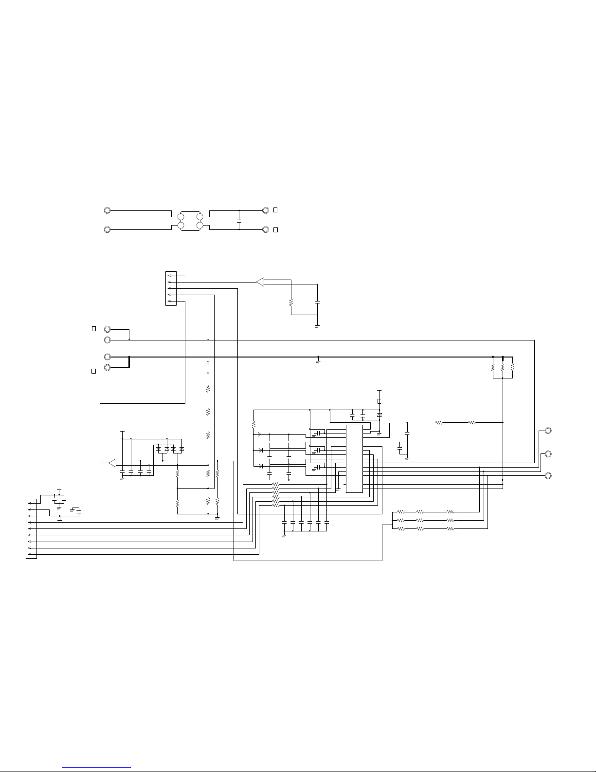
MAIN PCB
AOYG30LETL : K07BS-1205HUE-C1
AOYG36LETL : K07BS-1206HUE-C1
CAPACITOR PCB
AOYG30LETL : K05FB-0901HUE-P0
AOYG36LETL : K05FB-0900HUE-P0
FILTER PCB
AOYG30LETL : K05CW-0901HUE-FL0
AOYG36LETL : K05CW-0900HUE-FL0
TRANSISTOR PCB
( I P M )
AOYG30LETL : K07BT-0901HUE-TR0
AOYG36LETL : K07BT-0900HUE-TR0
INVERTER ASSEMBLY
AOYG30LETL : EZ-0121FHUE
AOYG36LETL : EZ-0121GHUE
OUTDOOR PCB CIRCUIT DIAGRAM
2013.02.07 9
F M
6
7
5
4
3
2
1
RED
BLACK
WHITE
YELLOW
GREEN
Page 11

5
4
3
2
1
5V
5V
C49
0R0
R40
10k
<1/10W>
D670
DAN217U
3
2
1
R41
1.0k
<1/10W>
C42
1000p
<B>
C670
0.1
<F>
R674
1.0k
<1/10W>
R84
1.0k
<1/10W>
5V
R85
4.7k
<1/10W>
C74
470p
<CH>
5V
I C1
MB90F462
17
16
2
35
3
59
58
60
21
34
47
27
28
29
30
31
32
33
57
41
42
43
44
10
9
8
7
5
6
4
22
23
2
1
3
49
24
13
48
19
1
61
62
63
64
20
18
15
14
55
54
53
52
51
50
46
45
12
39
38
37
36
40
26
25
11
56P63
P62
P46
P12
P50
P37
P36
P40
MD2
P11
P26
P02
P03
P04
P05
P06
P07
P10
C
P20
P21
P22
P23
P57
P56
P55
P54
P52
P53
P51
X0
X1
VCC
AVCC
P00
P01
P17
P13
P14
P15
P16
AVR
P24
P25
P30
P31
P32
P33
P34
P35
P60
P61
MD0
MD1
P44
P43
P42
P41
P45
RSTX
P27
AGND
GND
GND
X1
4.00MHz
<CSTLS>
R11
1.0k
<1/10W>
C11
0.1
<F>
R10
100k
<1/10W>
C12
0.1
<F>
5V
I C10
BU4842F
2
134
VDD
OUTNCGND
JM102
JM103
JM101
R903, R902, R901
10k <1/10W> x 3
5V
R6
1.0k
R7
10k
<1/10W>
5V
SW2
KSHC611BT
I C30
M93C66
5V
C30
0.1
<F>
R31
10k
<1/10W>
15V
C43
0.1
<F>
-8V
A
A
A
5V
R645
10k
<1/10W>
R651
10k
<1/10W>
5V
18V
D12
1SS355
I C5
7818
D6
D1FL20U
+
C9
220/
50V
C19
0.1 <F>
+
C10
10/50V
D1FL20U x 3D7
D8
D9
15V
C13
330/25V
+
12V
+
1
2
3IGO
1 32I
G
O
+
+
5V
D13
1SS355
T1
RPZ-1F
10
9
8
7
6
1
2
3
4
5
I C3
TOP243PN
D5
UF4005
R19
0R0
R12
0R0
C8
2200p
<E>
R18
150k
<2W>
R14
560k
<1/8W>
1%
15V
R15 - R17
510k
<1/8W> 1%
x 3
C211
33/
450V
+
1
2
3
4
8
7
5
M
S
S
C
S
S
D
+
R13
47
<1/10W>
C6
47/
35V
D4
1SS355
D2
1SS355
D3
UDZS8.2B
C7
0.1
<F>
F201
3.15A - 250V
FH200 FH201
FC51FL x 2
R900
10k
<1/10W>
C1
0.1
<F>
12V
D1
SLR-332VR
<RED>
R3
2.2k
<1/10W>
C5
0.1
<F>
12V
I C2
uLN2003ADR
16
15
14
13
12
11
10
9
8
7
6
5
4
3
2
11C
2C
3C
4C
5C
6C
7C
COM
1B
2B
3B
4B
5B
6B
7B
E
C2, C3
0.1 <F> x 2
5V
C4
10/
25V
+
JM1
R4
10k
<1/10W>
5V
JM2
R2
10k
<1/10W>
5V
U
X
V
Y
W
Z
D10
1SS355
-8V
+
C18
100/
25V
C14
470/
25V
R26 10k
<1/10W>
C22
0.1
<F>
C15
100/
25V
C17
100/
25V
C16
0.1
<F>
I C4
7805
C601
0.1
<F>
R603
22k
<1/10W>
R601
1.0k
<1/10W>
1%
R602
4.75k
<1/10W>
1%
+
C600
220/
25V
<A>
R600
1.0k
<1/10W>
1%
D600
DAN217U
5V
CT600
CT-1B
1
2
3
3
5 2
1
18 14
10
5 4 3
2
1
5
4 3
2
1
6
7
8
5V
5V
F110
3.15A - 250V
FH110
FH111
FC51FL x 2
C21
0.1
<B>
R23
1.0k
<1/10W>
Q200
2SC2412K
<BQ>
R24
1.0k
<1/10W>
R21
27k
<1/10W>
R20
39k
<1/10W>
C20
0.022
<B>
R22
1.0k
<1/10W>
1
3
2
132
4
K500
G5NB-1A
JM501
12V
JM502
JM504
JM503
CR500
RE1202
0.2 / 120
12V
L800
15V
15V
C802
0.1
<F>
R800
27k
<1/10W>
D801
ZP1027-TP
R801
22k
<1/10W>
+
C800
4.7/
50V
5V
5V
D800
DAN217U
C801
0.01
<B>
R803
1.0k
<1/10W>
Q801
DTA143EUA
Q800
DTC143EUA
R802
10k
<1/10W>
3
1
2
3
1
2
3
2 1
R90
1.0k
<1/10W>
C90
0.1
<F>
5V
R91
2.2k
<1/10W>
H Y I C 2 0
GK-30434E4
L60
BL02Rn1
L90
BL02Rn1
5V
R62
10k
<1/10W>
R60
10k
<1/10W>
R64
10k
<1/10W>
R69
10k
<1/10W>
C62
0.1
<F>
C61
0.1
<F>
C63
0.1
<F>
R68
13k
<1/10W>
R65
38.3k
<1/10W>
1%
R61
13k
<1/10W>
C60
0.1
<F>
R63
4.75k
<1/10W>
1%
18V
18V
D11
ZP1027-TP
C400
0.01
<F>
Q400
DTA143EUA
R401
22k
<1/10W>
R30
10k
<1/10W>
C401
1000p
<B>
Q401
DTC143EUA
A
A
5V
2
1
3
2
3
1
R403, R402
270
<1/10W>
1% x 2
5V
5V
R952, R951, R950
10k <1/10W> x 3
R953
1.0k
<1/10W>
R956
10k
<1/10W>
R954
1.0k
<1/10W>
R955
22k
<1/10W>
10
9
8
7
6
5
4
3
2
1
ACTPM CONTROL
CN400
1-1971032-4
RED
4
3
2
1
IPM CONTROL
CN40
1971032-9
WHITE
9
8
7
6
5
4
3
2
1
CN42
1971032-5
WHITE
PEAK LOAD CURRENT DETECTION
REVERSE CURRENT DETECTION
FO
DC VOLTAGE DETECTION
COMP POSITION DETECT
1
2
CN200
1-1747052-2
RED
DC VOLT I N
TM601
86028
TM600
86028
CN110
3-1747052-4
YELLOW
AC VOLT IN
2 L
1 N
SERIAL
B
W4
RED
SELIAL
CN500
1747052-1
WHITE
CN1
1871843-2
WHITE
POWER RELAY CONTROL
1
2
1
4
5
6
7
CN800
B5 ( 7-2.3 ) B-XASK-1-A
WHITE
DC FAN MOTOR
THERMISTOR ( PIPE TEMP. )
THERMISTOR ( DISCHARGE TEMP. )
CN62
1971032-3
WHITE
CN64
2-1971032-3
BLUE
THERMISTOR ( OUTDOOR TEMP. )
THERMISTOR ( COMPRESSOR TEMP. )
3
2
1
3
2
1
2
1
P-FANPWM
P-FAN-I N
P-SO
P-PR
P-LED
P-V4-DC
P-V4-AC
P-DBG-4
P-AN-TE
P-AN-TD
P-AN-TA
P-POWER
P-S I
P-AN-CT
P-S I
TCK
TRXD
TMODE
P-E2P-D I
P-EPV-A
P-U
P-X
P-V
P-Y
P-W
P-Z
P-POWER
P-E2P-SK
TAUX
P-TTR I P-FO
P-AN-DC
P-POS
P-U
P-V
P-W
P-X
P-Y
P-Z
P-E2P-CS
P-E2P-SK
P-E2P-D I
1
2
3
7
5
6
4
8CS
SK
D I
NC
VCC
DO
TEST
GND
TAUX
TTXD
TRXD
TMODE
TAUX3
TCK
P-FAN-I N
P-DBG-4
P-FANPWM
P-AN-CT
TTXD
TAUX3
P-POS
P-V4-AC
P-V4-DC
P-LED
P-PR
P-SO
P-TTR I P-FO
P-E2P-CS
P-EPV-B
P-EPV-D
P-EPV-C
P-AN-DC
P-AN-TE
P-AN-TA
P-AN-TD
I C700
TD62064
12V
C700
0.1
<F>
R703
R702
R700
R701
1.5k <1/10W> x 4
2
7
9
16
4
5
12
13
3
6
11
14
1
8
10
15
O1
O2
O3
O4
GND1
GND2
GND3
GND4
I 1
I 2
I 3
I 4
COM1
COM2
NC1
NC2
P-EPV-D
P-EPV-C
P-EPV-A
P-EPV-B
ELECTRIC EXPANSION VALVE
CN700
B06B-XARK-1-A
1
2
3
4
5
6
12V
*D801 : AOYG30LETL only
C91
0.01
<F>
C65
0.1
<F>
R52
10k
<1/10W>
5V
P-AFS
P-AFS
P-AN-CP
P-AN-CP
P-SW-PRS
P-SW-PRS
CN63
3-1971032-3
YELLOW
CN90
1-1871843-2
RED
PRESSURE SWITCH
CN65
1-1971032-3
RED
3
2
1
3
2
1
2
1
4-WAY VALVE
OUTDOOR UNIT
MAIN PCB
AOYG30LETL : K07BS-1205HUE-C1
AOYG36LETL : K07BS-1206HUE-C1
2013.01.18 10
Page 12
37
23
22
21
24
25
26
27
28
36
35
34
33
32
31
38
13
15
20
16
18
7
9
10
12
1
3
4
6 UP
VP1
VUFB
VUFS
VP
VP1
VVFB
VVFS
WP
VP1
VNO
VWFB
VWFS
NCNWNV
NU
W
V
U
P
WN
VN
UN
FO
CFO
C I N
VNC
VN1
-
+
7
5
6
+
-
1
3
2
3
2
1
3
2
1
I PM-G
I PM-G
I PM-G
POWER-GND
POWER-G
R55
0R0
C50
0R0
I P M-GND
I C70-2
BA2903F-E2
C161
0.1
<X7R>
D100
LL25XB60
I C301
AOYG30LETL : PS21765
AOYG36LETL : PS21767
C324
C325
C326
0.1 <F>
x 3
R360
68
<1/4W>
C311 - C316
1000p <B> x 6
I P M-GND
R80
5.6k
<1/10W>
1%
R108
4.3k
<1/10W>
1%
R81
33k
<1/10W>
1%
R107
39k
<1/10W>
1%
C72
470p
<B>
I P M-GND
C73
330p
<B>
C71
0.1
<F>
C70
10/
25V
+
I C70-1
BA2903F-E2
15V
D70, D71
DAN217Ux 2
C300
0.1
<F>
-8V
15V
C301
0.1
<F>
+
C308
47/
35V
I P M-G
9
8
7
6
5
4
3
2
1
+15V
-8V
UP
VP
WP
UN
VN
WN
L70
R71
150k
<1/3W>
1%
R70
120k
<1/3W>
1%
R69
120k
<1/3W>
1%
R77
143
<1/10W>
1%
R76
5.76k
<1/10W>
1%
470
<1/10W>
x 6
R316
R317
R318
R319
R320
R321
120k
<1/3W>
1% x 6
R68
R65
R62
R67
R64
R61
R66
R63
R60
150k
<1/3W>
1% x 3
R304
0R0
C332
0.1
<F>
+
C302
100/
35V
L300
BL02Rn1
15V
C327
0.022
<F>
C330
100p
<B>
D307
ZP1027-TP
1
2
3
4
5
2
3 4
1
+
-
W306
B
WHITE
P
N
POWER-G
CN301
1971032-9
WHITE
D301 - D303
US1J x 3
C323
C322
C321
0.22
<F>
x 3
C305
C304
C303
+
+
+
47/
35V
x 3
CN303
1971032-5
WHITE
TM101
ORANGE
TM102
BROWN
TM301
YELLOW
R284, R285, R302
0.04 <5W> x 3
R312
820
<1/10W>
TM305 RED
U
TM304 WHITE
V
TM303 BLACK
W
TM302
BLUE
OUTDOOR UNIT
TRANSISTOR PCB
( I P M )
AOYG30LETL : K07BT-0901HUE-TR0
AOYG36LETL : K07BT-0900HUE-TR0
Models :
2012.12.06 11
W307
B
BLACK
W16
B
RED
W17
B
BLACK
AOYG30LETL
AOYG36LETL
Page 13

12V
K101
DW12D1
-O ( M )
C108
3.3
<LE>
L102
N200500K1D7C
3
2
4
1
12V
CN100
172520-2
POWER RELAY CONTROL
1
2
SA100
RA-302M
L101
RCH3818-022PF07
C106
3.3
<LE>
4
3
2
1
W9
BLACK
CT OUT
C103
3.3
<LE>
L100
RCH3818-022PF07
1
2
4 3
C104, C105
0.022
<YE>
x 2
C100
3.3
<LE>
VA100
470V
<TNR>
VA101
470V
<TNR>
FH100
FH101
PFC5000-0502 x 2
L
N
L
N
TO INDOOR UNIT
EARTH
AC VOLT OUT
PTC OUT
C101
0.033
<YE>
C102
0.033
<YE>
W21
B
GRAY
F100
250V
10A
W2
B
WHITE
W1
B
BLACK
W18
B
WHITE
W17
B
BLACK
W3
B
GREEN
W20
B
WHITE
W19
B
BLACK
W25
B
ORANGE
W25
B
ORANGE
W28
B
ORANGE
W29
B
ORANGE
12V
K101
DW12D1
-O ( M )
C108
3.3
<LE>
L102
N200500K1D7C
3
2
4
1
R101
ZPR0RCH400
PTC THERMISTOR
12V
CN100
172520-2
POWER RELAY CONTROL
1
2
SA100
RA-302M
L101
RCV2515-010PF05
C106
3.3
<LE>
4
3
2
1
W9
BLACK
CT OUT
C103
3.3
<LE>
L100
RCV2515-010PF05
1
2
4 3
C104, C105
0.022
<YE>
x 2
C100
3.3
<LE>
VA100
470V
<TNR>
VA101
470V
<TNR>
FH100
FH101
PFC5000-0502 x 2
L
N
L
N
TO INDOOR UNIT
EARTH
AC VOLT OUT
C101
0.033
<YE>
C102
0.033
<YE>
W21
B
GRAY
F100
250V
10A
W2
B
WHITE
W1
B
BLACK
W18
B
WHITE
W17
B
BLACK
W3
B
GREEN
W20
B
WHITE
W19
B
BLACK
W28
B
ORANGE
W29
B
ORANGE
AOYG36LETL
FILTER PCB
K05CW-0900HUE-FL0
OUTDOOR UNIT
AOYG30LETL
FILTER PCB
K05CW-0901HUE-FL0
2012.12.06 12
POWER SOURCE
AC230V
50Hz
POWER SOURCE
AC230V
50Hz
Page 14

W7
B
YELLOW
W8
B
BLUE
W12
B
WHITE
W13
B
VIOLET
P
N
+
+
R200
220k
<2W>
POWER_G
OUTDOOR UNIT
AOYG30LETL
CAPACITOR PCB
K05FB-0901HUE-P0
2012.12.06 13
C201
660/
450V
C203
660/
450V
W7
B
YELLOW
W8
B
BLUE
W12
B
WHITE
W13
B
VIOLET
P
N
+
++
C200 - C202
660/
450V
x 3
POWER_G
AOYG36LETL
CAPACITOR PCB
K05FB-0900HUE-P0
Page 15

If you use a wireless remote control, the lamp
on the photo detector unit will output error codes
by way of blinking patterns.
If you use a wired type remote control, error
codes will appear on the remote control display.
See the lamp blinking patterns and error codes
in the table. An error display is displayed only
during running.
Indoor unit
Wired
remote
control
INDOOR UNIT
and WIRED REMOTE CONTROL
ERROR DETECTION
Description
OPERATION
lamp
(green)
TIMER
lamp
(orange)
ECONOMY
lamp
(green)
(1) (1)
Serial communication error
(1) (2)
Wired remote control communication error
(1)
(5)
Check run unfinished
(2)
(1)
Unit number or Refrigerant circuit address setting error
[Simultaneous Multi]
(2) (2)
Indoor unit capacity error
(2) (3)
Combination error
(2)
(4)
Connection unit number error (indoor slave unit)•
[Simultaneous Multi]
Connection unit number error (indoor unit or branch unit)
•
[Flexible Multi]
(2)
(7)
Master unit, slave unit set-up error
Power supply interruption error
[Simultaneous Multi]
(3)
(2)
Indoor unit PCB model
information error
(3) (5)
Manual auto switch error
(4) (1)
Inlet air temp. sensor error
(4) (2)
Indoor unit Heat Ex. Middle temp. sensor error
(5)
(1)
Indoor unit fan motor error
(5)
(3)
Drain pump error
(5) (7)
Damper error
(5) (15)
Indoor unit error
(6)
(2)
Outdoor unit main PCB model information error
or communication error
(6) (3)
Inverter error
(6)
(4)
Active filter error, PFC circuit error
(6) (5)
Trip terminal Lerror
(6)
(10)
Display PCB microcomputers communication error
: 0.5s on / 0.5s off
: 0.1s on / 0.1s off
( ) : Number of flashing
This is possible only on a wired remote control.
If an error occurs, the following display will be shown.
(“Er” will appear in the set room temperature display.)
2013.02.27 14
(3)
(1)
Indoor unit
Wired
remote
control
Description
OPERATION
lamp
(green)
TIMER
lamp
(orange)
ECONOMY
lamp
(green)
(7)
(1)
Discharge temp. sensor error
(7) (2)
Compressor temp. sensor error
(7) (3)
Outdoor unit Heat Ex. liquid temp. sensor error
(7) (4)
Outdoor temp. sensor error
(7)
(5)
Suction Gas temp. sensor error
(7) (6)
2-way valve temp. sensor error•
3-way valve temp. sensor error•
(7) (7)
Heat sink temp. sensor error
(8) (2)
Sub-cool Heat Ex. gas inlet temp. sensor error•
Sub-cool Heat Ex. gas outlet temp.sensor error•
(8) (3)
Liquid pipe temp. sensor error
(8) (4)
Current sensor error
(8) (6)
Discharge pressure sensor error•
Suction pressure sensor error•
High pressure switch error•
(9) (4)
Trip detection
(9) (5)
Compressor rotor position detection error
(permanent stop)
(9) (7)
Outdoor unit fan motor error
(9) (9)
4-way valve error
Coil (expansion valve) error
Outdoor unit fan motor 2 error
(10) (1)
Discharge temp. error
(10) (3)
Compressor temp. error
(10) (4)
High pressure error
(10) (5)
Low pressure error
(13) (2)
Branch boxes error
[Flexible Multi]
(9) (8)
(9) (10)
Remote control
.
Error codeUnit number of
indoor unit
EX. Self-diagnosis
Indoor unit display (option)
ECONOMY Lamp
(GREEN)
TIMER Lamp
(ORANGE)
OPERATION Lamp
(GREEN)
MANUAL AUTO
Page 16

DANGER
This part (Choke coil) generates high voltages.
Never touch this part.
SPECIAL INSTALLATION SETTING
PUMP DOWN (Refrigerant collecting operation)
Perform the following procedures to collect the refrigerant
when moving the indoor unit or the outdoor unit.
(1) Press the push-button switch on the circuit board once.
The LED on the circuit board starts flashing
(one second ON/one se-cond OFF).
This indicates the start of PUMP DOWN operation.
When the switch is pressed while the compressor is in operation,
PUMP DOWN operation starts automatically.
When the switch is pressed while the compressor is in stop,
the compressor starts to operate automatically,
and then move on to PUMP DOWN operation.
(2) PUMP DOWN operation continues for about 1 minute.
When PUMP DOWN operation is completed,
the compressor stops automatically.
Then close the 2-way valve and 3-way valve immediately.
(3) Turn the power off.
OUTDOOR UNIT
PUMP DOWN SW
2013.02.27 15
Page 17

1
Long Life Filter3
Intake Grille Assy
4 Filter Guide
5 Hook Bracket
6 Grille Hook
2013.02.13
PARTS
DECORATION PANEL
UTG-UGYA-W
16
9378252011
9378565012
2 Intake Grille 9378249011
9378253018
9378435018
9378250017
Ref. Description Part number
3
1
4
6
5
2
6
5
4
Page 18

11 Decoration Panel
12 Corner Panel A
13
Corner Panel (FUJITSU)
14 Panel Cover A
15 Panel Cover B
16 Drain Cover
2013.02.13
DECORATION PANEL
UTG-UGYA-W
9378242012
9378243019
9378243026
9378261013
9378262010
9378359017
Ref. Description Part number
11
15
16
12
12
13
14
14
14
12
17
Page 19

21 Flap
22 Poli Slider
31 Flap Spring
28 Joint B
25 Gear A
26 Motor Holder
24 Step motor
30 Joint Shaft
23 Joint C
2013.02.13
DECORATION PANEL
UTG-UGYA-W
18
9378254015
9375541019
27 Joint A 9378258013
9378356016
9378259010
9378256019
9378255012
9900467005
9378260016
9378357013
29 Gear B 9378257016
Ref. Description Part number
24
25
22
23
21
30
29
27
22
27
26
30
22
31
28
23
22
21
Page 20

3 Hook R
INDOOR UNIT
PARTS
4 Hook L
2013.02.13 19
9378197015
9378198012
1 Bell Mouth
2 Terminal Wire Cover
9378227019
9378548015
2
Ref. Description Part number
3
4
3
1
Page 21

20 Drain Pan Assy
2013.02.13 20
INDOOR UNIT
9378207011
20
12 Sensor Holder
13 Float Switch
16 Drain Pump Holder B
17 Pump Rubber
18 Drain Hose
19 Drain Port
9378329010
9900465018
11 Float Switch Sub Assy 9378593015
15 Pump Assy 9900464011
14 Drain Pump Sub Assy 9378592018
9375518011
9378426016
9378212015
9378213012
- Drain Hose
- Hose Band
9379665001
9379757010
Ref. Description Part number
15
13
12
11
19
18
14
17
16
Page 22

INDOOR UNIT
26 Turbo Fan Assy
28 Motor, DC Brushless
29 Rubber (Motor)
25 Cabinet C Sub Assy
2013.02.13 21
9378228016
27 Turbo Fan Washer 9378394018
9602716005
9378223011
9378570016
24 Cabinet B Sub Assy
23 Cabinet A Sub Assy
9378595019
9378594012
22 Top Plate Assy 9378395015
Ref. Description Part number
21 Evaporator Total Assy 9378580015
21
29
28
29
23
22
25
24
29
26
27
Page 23

33 Terminal 3P
INDOOR UNIT
34 Terminal 3P
35 Thermistor Holder A
36 Thermistor Holder B
31 Power Supply PCB
32 Main PCB (30)
37 Room Thermistor
38 Pipe Thermistor
2013.02.13 22
9306489045
9703345012
9378206014
9378330016
9707398366
9709245231
32 Main PCB (36) 9709245248
9900445010
9900470012
39 Remote Control 9318593013
Ref. Description Part number
34
39
36
37
33
35
38
31
32
Page 24

7
2
8
6
5
4
3
OUTDOOR UNIT
PARTS
2013.02.27 23
3 Top Panel Sub Assy 9374417032
4 Front Panel Sub Assy 9374414079
5
Service Panel Sub Assy
9374415052
7 Right Panel Sub Assy 9374416127
6 Emblem Rear 9351355005
8 Valve Cover 9374174010
1 Protective Net 9375381011
2 Thermo Holder 9375211011
Ref. Part numberDescription
12
13
10
9
1
11
10 Propeller Fan Assy 9366378020
9 Fan Motor 9602843015
11 Base Assy 9374166138
12 Drain Assy 9303029015
13 Drain Cap 313166024302
Page 25

31
32
33
23
24
29
26
27
25
30
22
21
28
Connector :
White
Connector :
Yellow
Connector :
Blue
Connector :
Red
OUTDOOR UNIT
2013.02.07 24
22 ACTPM 9707592016
29 Thermistor (36 only) 9704265012
25 Main PCB (30)
25 Main PCB (36)
9707667868
26 Filter PCB (30) 9707128215
26 Filter PCB (36) 9707128208
24 Capacitor PCB (30) 9707257052
24 Capacitor PCB (36) 9707257045
21 Transistor PCB (IPM) (30) 9707669077
21 Transistor PCB (IPM) (36) 9707669060
23 Choke Coil (30) 9900390020
23 Choke Coil (36) 9900223014
27 Terminal 9900203023
28 Heat Sink 9378530010
30 Discharge Thermitor 9900461003
31 Thermistor (Outdoor) 9900463007
32 Compressor Thermistor 9900466015
33
Heat Exchanger Thermistor
9900462000
9707667875
Ref. Part numberDescription
Page 26

2013.02.27 25
Ref.
41 3-way Valve Assy 9377958013
42 3-way Valve Assy 9377959010
43 Compressor 9810135001
44 Accumulator 9385005006
45 Solenoid 9970055034
46 Expansion Valve Coil 9900057039
Part numberDescription
43
46
42
41
45
OUTDOOR UNIT
44
Page 27

Ref.
56 Strainer Assy 9372524015
59 Check Joint Assy 9372802038
52 Condenser A Sub Assy 9374420308
53 Condenser A Assy 9374433056
58 4-way Valve 9900164010
57 4-way Valve Assy 9374425198
61 Pressure Switch 9900186012
54 Inlet Pipe (Cond) A Assy 9373461067
55
Outlet Pipe (Cond) A Assy
9374266104
51 Expansion Valve Assy 9370947144
60 Muffler 9372369050
Part numberDescription
OUTDOOR UNIT
2013.02.07 26
51
52
54
55
56
53
61
59
58
60
57
Page 28

Name and Shape Q'ty Part numberApplication
INDOOR UNIT
1
2
OUTDOOR UNIT
For drain
piping work
Drain pipe
Drain cap
9303029015
313166024302
ACCESSORIES
2013.02.27 27
Q'ty
1
8
2
1
1
1
1
3
1
1
1
2
Name and Shape
Template
(Carton top)
Washer
Coupler heat
insulation
Insulation
Drain hose assy
Hose band assy
Drain pipe
insulation
Binder (Large)
Binder (Small)
Wired remote
control
Remote Control
Cord
Tapping screw
( 4 x 16)
Application
For installing indoor unit
For installing indoor unit
For indoor side pipe joint
For installing drain pipe
For installing drain pipe
For installing drain pipe
For installing drain pipe
For electrincal wiring
For electrincal wiring
For connecting
remote control
For installing remote
control
DECORATION PANEL
Q'ty
4
4
4
2
Name and Shape
Hexagon Screw
Screw
Strap
Grille holding wire
Application
For mounting decoration panel
For installing grille holding wire
For installing corner panel
For installing intake grille
Page 29

2013.02.27 28
Name and Shape Application
OPTIONAL PARTS
UTY-RNNYM
UTR-YDZC
UTY-LRHYA2
Control unit on wall
Install the plate at outlet
when carrying out 3-way
direction operation.
Wireless remote control
and IR receiver unit
Wired remote
control
Air outlet shutter plate
Wireless remote control kit
Name and Shape Application
UTG-AGYA-W
UTG-BGYA-W
For ceiling hole
For making up difference
Wide panel
Panel spacer
Panel spacer
242 mm
600 mm
Panel
600 mm
Indoor
unit
950 mm
Install when the under roof
condition is expected to be the
humidity of over 80% and the
temperature of over 30 C.
Extrenal connect set
UTY-XWZX
Insulation kit
for high humidity
UTZ-KXGA
Use to connect with various
peripheral devices and air
conditioner PCB.
Fresh air intake kit
UTZ-VXGA
It can be taken in fresh air of up
to 10% of "high" air volume of the
indoor unit by attaching Fresh Air
lntake Kit to cassette type
indoor unit.
For air conditioner operation
High functional
wired remote
control
UTY-RVNYM
Simple remote
control
UTY-RSNYM
Page 30

1301G4160
 Loading...