

Fujitsu ASYG09LZCA, ASYG14LZCA, ASYG12LZCA, AOYG14LZCAN, AOYG12LZCAN Design & Technical Manual
...Page 1

DESIGN & TECHNICAL MANUAL
AIR CONDITIONER
Wall mounted type
INDOOR
ASYG09LZCA
ASYG12LZCA
ASYG14LZCA
OUTDOOR
AOYG09LZCAN
AOYG12LZCAN
AOYG14LZCAN
DR_AS020EF_01
2016.06.21
Page 2

Notices:
• Product specifications and design are subject to change without notice for future improvement.
• For further details, please check with our authorized dealer.
Copyright © 2016 Fujitsu General Limited. All rights reserved.
Page 3

CONTENTS
Part 1. INDOOR UNIT ........................................................................1
1. Product features ......................................................................................2
1-1. Model lineup ..............................................................................................................2
1-2. Features .....................................................................................................................2
2. Remote controller ....................................................................................4
2-1. Wireless remote controller ........................................................................................4
3. Specifications ..........................................................................................8
4. Dimensions ............................................................................................10
4-1. Models: ASYG09LZCA, ASYG12LZCA, and ASYG14LZCA ...................................10
5. Wiring diagrams .....................................................................................12
5-1. Models: ASYG09LZCA, ASYG12LZCA, and ASYG14LZCA ...................................12
6. Capacity table ........................................................................................13
6-1. Cooling capacity ......................................................................................................13
6-2. Heating capacity ......................................................................................................15
7. Fan performance ....................................................................................16
7-1. Air velocity distributions ...........................................................................................16
7-2. Airflow ......................................................................................................................18
8. Operation noise (sound pressure) .......................................................20
8-1. Noise level curve .....................................................................................................20
8-2. Sound level check point ...........................................................................................22
9. Safety devices ........................................................................................23
10. External input and output .....................................................................24
10-1.External input ..........................................................................................................24
10-2.External output ........................................................................................................26
11. Function settings ...................................................................................28
11-1.Function settings by using remote controller ..........................................................29
11-2.Custom code setting for wireless remote controller ................................................33
11-3.Switching the temperature unit of remote controller ...............................................34
12. Accessories ............................................................................................35
13. Optional parts ........................................................................................36
13-1.Controllers ...............................................................................................................36
13-2.Others .....................................................................................................................36
Page 4

CONTENTS (continued)
Part 2. OUTDOOR UNIT ................................................................. 37
1. Specifications ........................................................................................38
2. Dimensions ............................................................................................39
2-1. Models: AOYG09LZCAN, AOYG12LZCAN, and AOYG14LZCAN ......................... 39
3. Installation space ................................................................................... 40
3-1. Models: AOYG09LZCAN, AOYG12LZCAN, and AOYG14LZCAN ......................... 40
4. Refrigerant circuit ..................................................................................43
4-1. Models: AOYG09LZCAN and AOYG12LZCAN ...................................................... 43
4-2. Model: AOYG14LZCAN .......................................................................................... 44
5. Wiring diagrams .....................................................................................45
5-1. Models: AOYG09LZCAN and AOYG12LZCAN ...................................................... 45
5-2. Model: AOYG14LZCAN .......................................................................................... 46
6. Capacity compensation rate for pipe length and height difference .47
6-1. Models: AOYG09LZCAN and AOYG12LZCAN ...................................................... 47
6-2. Model: AOYG14LZCAN .......................................................................................... 48
7. Additional charge calculation ............................................................... 49
7-1. Models: AOYG09LZCAN and AOYG12LZCAN ...................................................... 49
7-2. Model: AOYG14LZCAN .......................................................................................... 49
8. Airflow .....................................................................................................50
8-1. Model: AOYG09LZCAN .......................................................................................... 50
8-2. Model: AOYG12LZCAN .......................................................................................... 50
8-3. Model: AOYG14LZCAN .......................................................................................... 50
9. Operation noise (sound pressure) ....................................................... 51
9-1. Noise level curve ..................................................................................................... 51
9-2. Sound level check point .......................................................................................... 53
10. Electrical characteristics ......................................................................54
11. Safety devices ........................................................................................55
12. Accessories ............................................................................................56
Page 5

Part 1. INDOOR UNIT
WALL MOUNTED TYPE:
ASYG09LZCA
ASYG12LZCA
ASYG14LZCA
Page 6

- 2 -
WALL MOUNTED
ASYG09-14LZCA
1. Product features
Implemented core technology provides easy-to-use product operations that realize a comfortable
space.
1-1. Model lineup
1-2. Features
Powerful operation
Energy saving control by using human sensor
Implemented human sensor detects the presence or absence of human in a room by sensing
movement of occupants, and suppress both of the air conditioner operation and energy consumption.
ASYG09LZCA
ASYG12LZCA
ASYG14LZCA
AOYG09LZCAN
AOYG12LZCAN
AOYG14LZCAN
20 minutes continuous operation by maximum airflow and
maximum compressor speed is possible. Rapid cooling
and heating makes the room comfortable quickly.
Example: Cooling operation
Powerful
Setting temp.
Normal mode
Time
Temperature
Human
sensor
Page 7

- 3 -
WALL MOUNTED
ASYG09-14LZCA
10 °C HEAT operation
The room temperature can be set to go no lower than 10 °C, thus ensuring that the room does
not get too cold when not occupied.
!
CAUTION
• When the room temperature is higher than 10 °C, 10 °C HEAT operation does not start. Operation starts and maintains the room temperature at 10 °C when the temperature drops below
10 °C.
• When 10 °C HEAT operation stops, the room set temperature quickly returns to the preset
temperature.
Outdoor unit low noise
Economy operation
5-mode timer (on, off, weekly, program, and sleep)
When air conditioner operates in large capacity, operation
noise of the outdoor unit will be suppressed. In case of the
room temperature being close to the set temperature,
operation noise might not decrease.
Economy operation is energy saving as the set
temperature of indoor unit is shifted by 1 °C, and the
maximum electric value of the outdoor unit is suppressed.
Example: Cooling operation
Weekly timer can be easily set by wireless remote controller.
On and off can be set up to 4 times in 1 day and up to 28 times in 1 week.
For other modes, program timer and sleep timer can be also selected by one
push.
10
°C
20
°C
“10 °C HEAT”
Button
ON
Indoor unit
operation
START
Rated
noise level
Down
Low noise
mode
Temp.
Economy operation
Shift
setting
temp
Control maxmum current
Nomal operation
Time
Set
temperature
Page 8

- 4 -
WALL MOUNTED
ASYG09-14LZCA
2. Remote controller
2-1. Wireless remote controller
Features
Simple function setting
Setting of the air conditioner selection function is performed by remote controller.
Weekly timer
Weekly timer can be easily set by wireless remote controller.
On and off can be set up to 4 times in a day, and up to 28 times in a week.
Program timer
The program timer operates the on and off timer once within a 24-hour period.
Sleep timer
The sleep timer function automatically corrects the temperature thermostat setting according to
the time setting to prevent excessive cooling and heating while sleeping.
• 5-mode timer setup (on, off, weekly, program, and sleep) available.
• Easy operation.
• Easy to change custom code (max. 4 custom code).
• Can be used jointly with wired remote controllers.
Cooling operation/Dry operation
When the sleep timer is set, the set temperature
automatically rises 1 °C every hour. The set
temperature can rise up to a maximum of 2 °C.
Heating operation
When the sleep timer is set, the set temperature
automatically drops 1 °C every 30 minutes. The
set temperature can drop to a maximum of 4 °C.
60 min
1 °C
2 °C
Timer setting
1 °C
2 °C
3 °C
4 °C
30 min
60 min
90 min
Timer setting
Page 9

- 5 -
WALL MOUNTED
ASYG09-14LZCA
Switching remote controller custom code
Code selector switch eliminates unit being wrongly switched. (Up to 4 codes can be set.)
* I.U.: Indoor unit
ABC D
ABCD
Mixed-up
I.U. I.U. I.U. I.U.
I.U. I.U. I.U. I.U.
After code change
Page 10

- 6 -
WALL MOUNTED
ASYG09-14LZCA
Overview
NOTE: Functions may differ by type of the indoor unit. For details, refer to the operation manual.
Display panel
To facilitate explanation, the accompanying illustration has been drawn to show all possible indicators; in
actual operation, however, the display will only show those indicators appropriate to the current operation.
Signal
transmitter
10°C HEAT
button
TEMP.
button
POWERFUL
button
Start/Stop
button
TIMER SETTING button
SEND button
SELECT button
NEXT button
BACK button
OUTDOOR UNIT
LOW NOISE button
SWING button
SET button
WEEKLY button
ON/OFF button
SLEEP button
MODE button
SENSOR button
FAN button
RESET button
CLOCK ADJUST button
ECONOMY button
Mode indicator
ENERGY SAVING mode
indicator
LOW NOISE mode
indicator
Turns on when
the SENSOR button is operated.
Clock and Timer indicator
SEND indicator
Transmit indicator
Temperature indicator
Fan speed indicator
Swing indicator
Page 11

- 7 -
WALL MOUNTED
ASYG09-14LZCA
Specifications
Controller
Holder
Unit: mm
Size (H × W × D) mm 205 × 61 × 17
Weight g 122 (without batteries)
Unit: mm
Size (H × W × D) mm 150 × 69.3 × 26.2
Weight g 27
Top view
Front view Side view
205
1761
48.5
5.5
26.2
69.3
6.5
Front View Side View
Bottom View
Ø 3.5
(Hole)
150
106.8
Hole
3.5
2-R
Page 12

- 8 -
WALL MOUNTED
ASYG09-14LZCA
3. Specifications
Typ e
Wall mounted
Inverter heat pump
Model name
ASYG09LZCA
ASYG12LZCA ASYG14LZCA
Power supply 230 V ~ 50 Hz
Available voltage range 198—264 V
Capacity
Cooling
Rated
kW 2.50 3.50 4.20
Btu/h 8,500 11,900 14,300
Min.—Max.
kW 0.90—4.65 0.90—4.80 0.90—6.40
Btu/h 3,100—15,800 3,100—16,300 3,100—21,800
Heating
Rated
kW 3.20 4.00 5.40
Btu/h 10,900 13,600 18,400
Min.—Max.
kW 0.90—7.20 0.90—7.40 0.90—8.90
Btu/h 3,100—24,500 3,100—25,200 3,100—30,300
Input power
Cooling
Rated
kW
0.48 0.80 1.05
Max. 0.85 0.99 1.56
Heating
Rated 0.555 0.76 1.17
Max. 1.93 1.94 2.19
Fan
HIGH
W
23 23 32
MED 13 13 20
LOW 9 9 12
QUIET 5 5 6
Current
Cooling
Rated A
2.7 4.0 4.8
Heating 2.9 3.9 5.3
EER Cooling
kW/kW
5.21 4.38 4.00
COP Heating 5.77 5.26 4.62
Power factor
Cooling
%
77 87 95
Heating 83 85 96
Moisture removal L/h (pints/h) 1.0 (2.1) 1.1 (2.3) 1.7 (3.6)
Maximum operating current *1
Cooling
A
9.4 9.4 9.9
Heating 11.9 11.9 14.9
Fan
Airflow rate
Cooling
HIGH
m3/h
830 900
MED 680 780
LOW 580 630
QUIET 380 440
Heating
HIGH 830 900
MED 680 780
LOW 580 630
QUIET 380 500
Type × Q'ty Cross flow fan × 1
Motor output W 61
Sound pressure level *2
Cooling
HIGH
dB (A)
42 45
MED 37 40
LOW 32 34
QUIET 23 26
Heating
HIGH 41 44
MED 35 39
LOW 31 33
QUIET 23 27
Heat exchanger type
Dimensions (H × W × D)
mm
Main: 384 × 720 × 30
Sub 1: 84 × 720 × 13.3
Sub 2: 126 × 720 × 13.3
Fin pitch Main: 1.2, Sub 1 and Sub 2: 1.4
Rows × Stages Main: 3 × 24, Sub 1: 1 × 4, Sub 2: 1 × 6
Pipe type Copper tube
Fin type Aluminum
Enclosure
Material Polystyrene
Color
White
Approximate color of MUNSELL 5PB 9. 25/0.5
Dimensions
(H × W × D)
Net
mm
295 × 940 × 270
Gross 365 × 1,040 × 355
Weight
Net
kg
14
Gross 17
Connection pipe
Size
Liquid
mm (in)
Ø 6.35 (Ø 1/4)
Gas Ø 9.52 (Ø 3/8) Ø 12.7 (Ø 1/2)
Method Flare
Drain hose
Material PP+LLDPF
Size mm Ø 13.8 (I.D.), Ø 15.8 to Ø 16.7 (O.D.)
Operation range
Cooling
°C 18 to 32
%RH 80 or less
Heating °C 16 to 30
Remote controller type Wireless (Wired [option])
NOTES:
• Specifications are based on the following conditions:
– Cooling: Indoor temperature of 27 °CDB/ 19 °CWB, and outdoor temperature of 35 °CDB/ 24 °CWB.
– Heating: Indoor temperature of 20 °CDB/ 15 °CWB, and outdoor temperature of 7 °CDB/ 6 °CWB.
– Pipe length: 5 m, Height difference: 0 m. (Between outdoor unit and indoor unit.)
• Pro tective function might work when using it outside the operation range.
• *1: Maximum current is maximum value when operated within the operation range.
• *2: S ound pressure level:
– Measured values in manufacturer’s anechoic chamber.
– Because of the surrounding sound environment, the sound levels measured in actual installation conditions might be higher than the specified values here.
Page 13

- 9 -
WALL MOUNTED
ASYG09-14LZCA
Model name ASYG09LZCA ASYG12LZCA ASYG14LZCA
Energy efficiency class
Cooling
A
+++
A
+++
A
++
Heating (Average)
A
+++
A
++
A
+
Pdesign
Cooling
kW
2.5 (35 °C) 3.5 (35 °C) 4.2 (35 °C)
Heating (Average) 2.5 (-10 °C) 3.5 (-10 °C) 4.2 (-10 °C)
SEER Cooling
kWh/kWh
9.51 8.60 7.92
SCOP Heating (Average) 5.31 4.93 4.44
Annual energy consumption
QCE
kWh/a
92 142 186
QHE (Average) 659 993 1322
Sound power level
Cooling
HIGH dB (A)
56 56 59
Heating 56 56 59
Page 14

- 10 -
WALL MOUNTED
ASYG09-14LZCA
4. Dimensions
4-1. Models: ASYG09LZCA, ASYG12LZCA, and ASYG14LZCA
Unit: mm
375
for pipe inlet Ø 65
for pipe inlet Ø 65
387
Outline of unit
470 470
270
43
295
295
940
940
387
83
77
393
40
9
43
Page 15

- 11 -
WALL MOUNTED
ASYG09-14LZCA
Installation space requirement
Provide sufficient installation space for product safety.
Outline of unit
Unit: mm
50 or more
127 or more
50 or more
133 or more
1,500 or more
50 or more
84 or more
1,800 or more
Page 16

- 12 -
WALL MOUNTED
ASYG09-14LZCA
5. Wiring diagrams
5-1. Models: ASYG09LZCA, ASYG12LZCA, and ASYG14LZCA
Page 17

- 13 -
WALL MOUNTED
ASYG09-14LZCA
6. Capacity table
Capacity tables show each of following values calculated based on the outdoor temperature and the
indoor temperature, under given Airflow Rate (AFR):
For cooling capacity: Total Capacity (TC), Sensible Heat Capacity (SHC), and Input Power (IP)
For heating capacity: Total Capacity (TC) and Input Power (IP)
6-1. Cooling capacity
Model: ASYG09LZCA
Model: ASYG12LZCA
AFR
m3/h
830
Indoor temperature
°CDB 18 21 23 25 27 29 32
°CWB 12 15 16 18 19 21 23
Outdoor temperature
°CDB
TC SHC IP TC SHC IP TC SHC IP TC SHC IP TC SHC IP TC SHC IP TC SHC IP
kW kW kW kW kW kW kW
-10.0 2.31 2.27 0.19 2.58 2.28 0.19 2.71 2.38 0.19 2.85 2.49 0.20 2.93 2.68 0.19 3.10 2.67 0.19 3.28 2.76 0.20
-5.0 2.27 2.21 0.21 2.53 2.22 0.21 2.66 2.32 0.21 2.79 2.43 0.22 2.87 2.62 0.22 3.04 2.61 0.22 3.21 2.70 0.22
0.0 2.22 2.16 0.22 2.47 2.18 0.22 2.60 2.28 0.22 2.73 2.37 0.23 2.81 2.57 0.22 2.97 2.56 0.22 3.14 2.65 0.23
5.0 2.17 2.13 0.23 2.42 2.14 0.23 2.55 2.24 0.23 2.67 2.33 0.24 2.75 2.52 0.23 2.91 2.50 0.23 3.08 2.60 0.24
10.0 2.12 2.07 0.21 2.36 2.08 0.21 2.49 2.18 0.22 2.61 2.27 0.23 2.69 2.46 0.22 2.84 2.44 0.22 3.01 2.54 0.23
15.0 2.07 2.04 0.26 2.31 2.04 0.26 2.43 2.14 0.26 2.55 2.22 0.27 2.63 2.41 0.26 2.78 2.39 0.26 2.94 2.49 0.27
20.0 2.34 2.29 0.33 2.61 2.30 0.33 2.70 2.40 0.34 2.87 2.51 0.34 2.96 2.71 0.34 3.14 2.70 0.34 3.32 2.77 0.35
25.0 2.22 2.17 0.38 2.48 2.18 0.38 2.56 2.28 0.38 2.73 2.39 0.39 2.81 2.57 0.39 2.98 2.56 0.39 3.15 2.63 0.39
30.0 2.10 2.05 0.42 2.34 2.07 0.42 2.42 2.16 0.42 2.58 2.25 0.43 2.66 2.43 0.43 2.82 2.43 0.44 2.98 2.48 0.44
35.0 1.98 1.93 0.46 2.20 1.94 0.47 2.28 2.03 0.47 2.43 2.12 0.48 2.50 2.29 0.48 2.65 2.28 0.49 2.80 2.33 0.49
40.0 1.76 1.59 0.43 1.96 1.73 0.44 2.03 1.81 0.44 2.16 1.88 0.45 2.23 2.04 0.45 2.36 2.03 0.45 2.50 2.08 0.45
46.0 1.51 1.50 0.43 1.69 1.60 0.44 1.74 1.68 0.44 1.85 1.75 0.45 1.92 1.89 0.45 2.03 1.88 0.45 2.13 1.93 0.45
AFR
m3/h
830
Indoor temperature
°CDB 18 21 23 25 27 29 32
°CWB 12 15 16 18 19 21 23
Outdoor temperature
°CDB
TC SHC IP TC SHC IP TC SHC IP TC SHC IP TC SHC IP TC SHC IP TC SHC IP
kW kW kW kW kW kW kW
-10.0 3.02 2.85 0.28 3.36 2.86 0.28 3.54 3.00 0.29 3.77 3.18 0.29 3.83 3.38 0.29 4.05 3.35 0.29 4.28 3.57 0.30
-5.0 2.99 2.82 0.33 3.34 2.83 0.33 3.51 2.97 0.34 3.74 3.14 0.34 3.80 3.34 0.34 4.02 3.32 0.34 4.25 3.54 0.35
0.0 2.97 2.80 0.37 3.31 2.81 0.37 3.49 2.94 0.37 3.71 3.12 0.38 3.77 3.32 0.38 3.99 3.30 0.38 4.22 3.52 0.39
5.0 2.95 2.78 0.39 3.29 2.80 0.39 3.46 2.92 0.40 3.68 3.10 0.40 3.74 3.30 0.41 3.96 3.28 0.41 4.19 3.49 0.42
10.0 2.93 2.75 0.40 3.26 2.77 0.40 3.43 2.90 0.41 3.65 3.07 0.41 3.71 3.26 0.41 3.93 3.25 0.41 4.15 3.47 0.43
15.0 2.90 2.74 0.42 3.24 2.76 0.42 3.40 2.88 0.42 3.62 3.05 0.43 3.68 3.24 0.43 3.90 3.23 0.43 4.12 3.44 0.44
20.0 3.28 3.09 0.55 3.65 3.11 0.56 3.77 3.25 0.56 4.02 3.44 0.57 4.15 3.66 0.57 4.40 3.64 0.57 4.64 3.88 0.58
25.0 3.12 2.93 0.63 3.47 2.95 0.63 3.59 3.09 0.64 3.83 3.27 0.64 3.95 3.48 0.64 4.18 3.46 0.65 4.42 3.68 0.66
30.0 2.95 2.77 0.70 3.28 2.78 0.71 3.40 2.91 0.71 3.62 3.09 0.71 3.73 3.28 0.72 3.96 3.27 0.73 4.18 3.49 0.74
35.0 2.77 2.61 0.77 3.08 2.62 0.78 3.19 2.74 0.79 3.40 2.90 0.80 3.50 3.09 0.80 3.71 3.08 0.81 3.92 3.27 0.82
40.0 2.34 2.33 0.72 2.60 2.34 0.73 2.69 2.44 0.74 2.87 2.58 0.74 2.96 2.75 0.74 3.14 2.74 0.75 3.31 2.92 0.76
46.0 1.98 1.97 0.72 2.22 2.10 0.73 2.29 2.20 0.74 2.43 2.32 0.74 2.50 2.48 0.74 2.66 2.47 0.75 2.81 2.63 0.76
Page 18

- 14 -
WALL MOUNTED
ASYG09-14LZCA
Model: ASYG14LZCA
AFR
m3/h
900
Indoor temperature
°CDB 18 21 23 25 27 29 32
°CWB 12 15 16 18 19 21 23
Outdoor temperature
°CDB
TC SHC IP TC SHC IP TC SHC IP TC SHC IP TC SHC IP TC SHC IP TC SHC IP
kW kW kW kW kW kW kW
-10.0 3.69 2.91 0.36 4.11 3.24 0.37 4.32 3.26 0.37 4.53 3.57 0.39 4.67 3.68 0.37 4.94 3.89 0.38 5.22 4.12 0.39
-5.0 3.63 2.85 0.39 4.04 3.18 0.40 4.25 3.20 0.40 4.46 3.50 0.42 4.59 3.61 0.41 4.86 3.82 0.41 5.14 4.04 0.42
0.0 3.57 2.81 0.41 3.98 3.13 0.41 4.18 3.16 0.41 4.39 3.46 0.43 4.52 3.56 0.42 4.79 3.77 0.42 5.06 3.99 0.43
5.0 3.52 2.77 0.41 3.92 3.09 0.42 4.12 3.11 0.42 4.32 3.40 0.44 4.45 3.51 0.43 4.71 3.71 0.43 4.98 3.93 0.44
10.0 3.46 2.72 0.43 3.85 3.03 0.43 4.05 3.06 0.43 4.25 3.34 0.45 4.38 3.45 0.44 4.64 3.65 0.44 4.90 3.86 0.45
15.0 3.40 2.67 0.45 3.79 2.98 0.46 3.98 3.00 0.46 4.18 3.28 0.48 4.31 3.38 0.47 4.56 3.59 0.47 4.82 3.79 0.48
20.0 3.91 3.29 0.73 4.35 3.31 0.75 4.50 3.46 0.75 4.80 3.60 0.75 4.95 3.90 0.75 5.24 3.87 0.76 5.54 4.14 0.76
25.0 3.72 3.13 0.82 4.15 3.15 0.83 4.29 3.29 0.84 4.57 3.44 0.85 4.71 3.71 0.85 5.00 3.70 0.86 5.28 3.94 0.86
30.0 3.53 2.97 0.92 3.93 2.99 0.93 4.07 3.12 0.94 4.34 3.26 0.95 4.47 3.52 0.95 4.74 3.51 0.96 5.01 3.74 0.96
35.0 3.32 2.79 1.02 3.70 2.81 1.03 3.82 2.94 1.04 4.07 3.06 1.04 4.20 3.31 1.05 4.45 3.29 1.06 4.70 3.51 1.06
40.0 2.92 2.45 1.00 3.25 2.46 1.02 3.36 2.58 1.02 3.58 2.69 1.03 3.69 2.90 1.03 3.91 2.89 1.04 4.13 3.08 1.05
46.0 2.42 2.24 0.98 2.70 2.25 1.00 2.79 2.35 1.00 2.97 2.45 1.02 3.06 2.64 1.02 3.24 2.63 1.03 3.44 2.81 1.02
Page 19

- 15 -
WALL MOUNTED
ASYG09-14LZCA
6-2. Heating capacity
Model: ASYG09LZCA
Model: ASYG12LZCA
Model: ASYG14LZCA
AFR
m3/h
830
Indoor temperature
16 18 20 22 24
Outdoor temperature
°CDB °CWB
TC IP TC IP TC IP TC IP TC IP
kW kW kW kW kW
-25 -26 3.53 2.15 3.44 2.19 3.36 2.23 3.27 2.32 3.19 2.36
-20 -21 4.45 2.16 4.34 2.20 4.24 2.24 4.13 2.33 4.02 2.38
-15 -16 4.88 2.17 4.77 2.21 4.65 2.25 4.53 2.34 4.42 2.39
-10 -11 5.19 2.13 5.07 2.17 4.95 2.22 4.82 2.30 4.70 2.35
-5 -7 5.50 2.10 5.37 2.14 5.24 2.18 5.11 2.27 4.98 2.31
0 -2 5.65 2.06 5.52 2.10 5.38 2.14 5.25 2.23 5.11 2.27
5 3 6.97 1.88 6.81 1.92 6.64 1.95 6.47 2.03 6.31 2.07
7 6 7.55 1.85 7.38 1.89 7.20 1.93 7.02 2.01 6.84 2.05
10 8 8.35 1.84 8.15 1.88 7.95 1.91 7.75 1.99 7.55 2.03
15 10 8.65 1.63 8.45 1.67 8.24 1.70 8.03 1.77 7.83 1.80
20 15 8.97 1.45 8.75 1.48 8.54 1.51 8.33 1.57 8.11 1.60
24 18 9.29 1.29 9.07 1.32 8.85 1.34 8.63 1.40 8.41 1.43
AFR
m3/h
830
Indoor temperature
16 18 20 22 24
Outdoor temperature
°CDB °CWB
TC IP TC IP TC IP TC IP TC IP
kW kW kW kW kW
-25 -26 3.75 2.15 3.66 2.19 3.57 2.23 3.39 2.32 3.30 2.36
-20 -21 4.79 2.16 4.67 2.20 4.56 2.24 4.33 2.33 4.22 2.38
-15 -16 5.11 2.17 4.99 2.21 4.87 2.25 4.63 2.34 4.50 2.39
-10 -11 5.55 2.13 5.42 2.18 5.29 2.22 5.03 2.31 4.89 2.35
-5 -7 6.00 2.10 5.85 2.14 5.71 2.18 5.42 2.27 5.28 2.31
0 -2 6.17 2.07 6.02 2.11 5.87 2.15 5.58 2.23 5.43 2.28
5 3 7.52 1.88 7.34 1.92 7.16 1.96 6.80 2.04 6.62 2.08
7 6 7.77 1.86 7.58 1.90 7.40 1.94 7.03 2.02 6.84 2.06
10 8 8.58 1.85 8.38 1.89 8.18 1.93 7.77 2.00 7.56 2.04
15 10 8.90 1.64 8.68 1.68 8.47 1.71 8.05 1.78 7.84 1.81
20 15 9.22 1.46 9.00 1.49 8.78 1.52 8.34 1.58 8.12 1.61
24 18 9.55 1.30 9.32 1.33 9.10 1.35 8.64 1.41 8.41 1.43
AFR
m
3
/h
900
Indoor temperature
16 18 20 22 24
Outdoor temperature
°CDB °CWB
TC IP TC IP TC IP TC IP TC IP
kW kW kW kW kW
-25 -26 5.07 2.92 4.95 2.97 4.83 3.03 4.58 3.15 4.46 3.21
-20 -21 5.80 2.93 5.66 2.99 5.52 3.04 5.25 3.16 5.11 3.22
-15 -16 6.53 2.94 6.38 3.00 6.22 3.05 5.91 3.18 5.75 3.24
-10 -11 7.41 2.83 7.24 2.88 7.06 2.93 6.71 3.05 6.53 3.11
-5 -7 8.30 2.71 8.10 2.76 7.90 2.81 7.51 2.92 7.31 2.98
0 -2 8.93 2.60 8.72 2.64 8.51 2.69 8.08 2.80 7.87 2.85
5 3 9.18 2.18 8.96 2.22 8.74 2.27 8.30 2.36 8.09 2.41
7 6 9.34 2.10 9.12 2.15 8.90 2.19 8.45 2.28 8.23 2.32
10 8 9.72 1.97 9.49 2.01 9.26 2.05 8.80 2.13 8.57 2.17
15 10 10.12 1.75 9.88 1.79 9.64 1.82 9.16 1.89 8.91 1.93
20 15 10.53 1.55 10.28 1.59 10.03 1.62 9.53 1.68 9.28 1.72
24 18 10.96 1.38 10.70 1.41 10.44 1.44 9.92 1.50 9.66 1.53
Page 20

- 16 -
WALL MOUNTED
ASYG09-14LZCA
7. Fan performance
7-1. Air velocity distributions
Models: ASYG09LZCA and ASYG12LZCA
Measuring conditions
Fan speed Operation mode
HIGH FAN
Top vi ew
Vertical airflow direction louver: Up
Horizontal airflow direction louver: Center
Top vi ew
Vertical airflow direction louver: Up
Horizontal airflow direction louver: Left & Right
Side view
Vertical airflow direction louver: Up
Horizontal airflow direction louver: Center
Side view
Vertical airflow direction louver: Down
Horizontal airflow direction louver: Center
2
1
0
1
2
Unit: m/s(m)
(m)
01234567
8
9
2.0
1.0
0.5
3
2
1
0
1
2
3
Unit: m/s
(m)
(m)
012345678
9
2.0
2.0
1.0
1.0
0.5
0.5
2.0
0.5
1.0
3
2
1
0
Unit: m/s
(m)
(m)
012345678
9
2.0
0.5
1.0
3
2
1
0
Unit: m/s
(m)
(m)
012345678
9
Page 21

- 17 -
WALL MOUNTED
ASYG09-14LZCA
Model: ASYG14LZCA
Measuring conditions
Fan speed Operation mode
HIGH FAN
Top view
Vertical airflow direction louver: Up
Horizontal airflow direction louver: Ce nter
Top view
Vertical airflow direction louver: Up
Horizontal airflow direction louver: Le ft & Right
Side view
Vertical airflow direction louver: Up
Horizontal airflow direction louver: Ce nter
Side view
Vertical airflow direction louver: Down
Horizontal airflow direction louver: Ce nter
2
1
0
1
2
Unit: m/s(m)
(m)
01234567
8
9
2.0
1.0
0.5
2.0
2.0
1.0
1.0
0.5
0.5
3
2
1
0
1
2
3
Unit: m/s
(m)
(m)
01234567
8
9
2.0
1.0
0.5
3
2
1
0
Unit: m/s
(m)
(m)
012345678
9
2.0
1.0 0.5
3
2
1
0
Unit: m/s
(m)
(m)
012345678
9
Page 22

- 18 -
WALL MOUNTED
ASYG09-14LZCA
7-2. Airflow
Models: ASYG09LZCA and ASYG12LZCA
Cooling
Heating
Fan speed Airflow
HIGH
m
3
/h
830
l/s 231
CFM 489
MED
m
3
/h
680
l/s 189
CFM 400
LOW
m
3
/h
580
l/s 161
CFM 341
QUIET
m
3
/h
380
l/s 106
CFM 224
Fan speed Airflow
HIGH
m
3
/h
830
l/s 231
CFM 489
MED
m
3
/h
680
l/s 189
CFM 400
LOW
m
3
/h
580
l/s 161
CFM 341
QUIET
m
3
/h
380
l/s 106
CFM 224
Page 23

- 19 -
WALL MOUNTED
ASYG09-14LZCA
Model: ASYG14LZCA
Cooling
Heating
Fan speed Airflow
HIGH
m
3
/h
900
l/s 250
CFM 530
MED
m
3
/h
780
l/s 217
CFM 459
LOW
m
3
/h
630
l/s 175
CFM 371
QUIET
m
3
/h
440
l/s 122
CFM 259
Fan speed Airflow
HIGH
m
3
/h
900
l/s 250
CFM 530
MED
m
3
/h
780
l/s 217
CFM 459
LOW
m
3
/h
630
l/s 175
CFM 371
QUIET
m
3
/h
500
l/s 139
CFM 294
Page 24

- 20 -
WALL MOUNTED
ASYG09-14LZCA
8. Operation noise (sound pressure)
8-1. Noise level curve
Model: ASYG09LZCA
Cooling Heating
Model: ASYG12LZCA
Cooling Heating
NC-65
NC-60
NC-55
NC-50
NC-45
NC-40
NC-35
NC-30
NC-25
NC-20
NC-15
Octave band sound pressure level, dB: (0 dB=0.0002 µbar)
Octave band center frequency, Hz
80
70
60
50
40
30
20
10
0
63 125 250 500 1,000 2,000 4,000 8,000
HIGH
QUIET
NC-65
NC-60
NC-55
NC-50
NC-45
NC-40
NC-35
NC-30
NC-25
NC-20
NC-15
Octave band sound pressure level, dB: (0 dB=0.0002 µbar)
Octave band center frequency, Hz
80
70
60
50
40
30
20
10
0
63 125 250 500 1,000 2,000 4,000 8,000
HIGH
QUIET
NC-65
NC-60
NC-55
NC-50
NC-45
NC-40
NC-35
NC-30
NC-25
NC-20
NC-15
Octave band sound pressure level, dB: (0 dB=0.0002 µbar)
Octave band center frequency, Hz
80
70
60
50
40
30
20
10
0
63 125 250 500 1,000 2,000 4,000 8,000
HIGH
QUIET
NC-65
NC-60
NC-55
NC-50
NC-45
NC-40
NC-35
NC-30
NC-25
NC-20
NC-15
Octave band sound pressure level, dB: (0 dB=0.0002 µbar)
Octave band center frequency, Hz
80
70
60
50
40
30
20
10
0
63 125 250 500 1,000 2,000 4,000 8,000
HIGH
QUIET
Page 25

- 21 -
WALL MOUNTED
ASYG09-14LZCA
Model: ASYG14LZCA
Cooling Heating
NC-65
NC-60
NC-55
NC-50
NC-45
NC-40
NC-35
NC-30
NC-25
NC-20
NC-15
Octave band sound pressure level, dB: (0 dB=0.0002 µbar)
Octave band center frequency, Hz
80
70
60
50
40
30
20
10
0
63 125 250 500 1,000 2,000 4,000 8,000
HIGH
QUIET
NC-65
NC-60
NC-55
NC-50
NC-45
NC-40
NC-35
NC-30
NC-25
NC-20
NC-15
Octave band sound pressure level, dB: (0 dB=0.0002 µbar)
Octave band center frequency, Hz
80
70
60
50
40
30
20
10
0
63 125 250 500 1,000 2,000 4,000 8,000
HIGH
QUIET
Page 26

- 22 -
WALL MOUNTED
ASYG09-14LZCA
8-2. Sound level check point
Microphone
Microphone
1 m
0.8 m
Page 27

- 23 -
WALL MOUNTED
ASYG09-14LZCA
9. Safety devices
*PCB: Printed Circuit Board
Type of
protection
Protection form
Model
ASYG09LZCA ASYG12LZCA ASYG14LZCA
Circuit protection Current fuse (PCB*) 250 V, 3.15 A
Fan motor
protection
Thermal
protector
program
Activate
105±10 °C
Fan motor stop
Reset
90±10 °C
Fan motor restart
Page 28

- 24 -
WALL MOUNTED
ASYG09-14LZCA
10. External input and output
With using external input and output functions, this product can be operated inter-connectedly with
an external device.
10-1. External input
With using external input function, some functions on this product can be controlled from an external
device.
• “Operation/Stop” mode or "Forced stop" mode can be selected with function setting of indoor unit.
• A twisted pair cable (22AWG) should be used. Maximum length of cable is 150 m.
• The wire connection should be separate from the power cable line.
Control input (Operation/Stop or Forced stop)
The air conditioner can be remotely operated by means of the following on-site work.
Unit operation is started at the following contents by adding the contact input of a commercial on/
off switch to a connector on the external control PCB and turning it on.
Circuit diagram example
When function setting is “Operation/Stop” mode
Connector Input Output Remarks
CNA01 Control input —
See external input/output
settings for details.
CNB01 — Operation status output
CNB02 — Error status output
Unit operation Initial setting after power is on
Starting mode other than initial
setting
Operation mode Auto changeover Mode at previous operation
Set temperature 24 °C Temperature at previous operation
Airflow mode AUTO Mode at previous operation
Air direction (swing) Standard air direction (swing: off) Air direction at previous operation
• Contact capacity: DC 24 V or more, 10
mA or more.
• *: Make the distance from the PCB to
the connected unit within 10 m.
• Use non-polar relays and switches.
Signal
Locally purchased
Indoor unit
control PCB
Communication kit
Optional parts
Connector
1
3
10 m*
Connected unit
Example: Switch
Operation
Stop
On
Off
Input signal
Indoor unit
Page 29

- 25 -
WALL MOUNTED
ASYG09-14LZCA
When function setting is “Forced stop” mode
When function setting is "Operation/Stop" mode 2
NOTE: When "Operation/Stop" mode 2 function is used with forming a remote controller group,
connect the same equipment to each indoor unit within the group.
Optional part
* For operating the external function, the wall mounted type requires the communication kit in
addition to the wire (UTY-XWZXZ5).
Part name Model name Exterior
External connect kit UTY-XWZXZ5
External input wire
Communication kit UTY-TWBXF1
Remote controller
On On On
Input signal
Indoor unit
Command
Remote control
operation invalidity
On
Off
Operation
Stop
Forced stop
Normal
On
Input
Off
Operation
Indoor unit
Stop
(R.C. disabled)
Remote controller
On OnOff
Page 30

- 26 -
WALL MOUNTED
ASYG09-14LZCA
10-2. External output
With using external output function, operating status of this product can be transmitted to the
external device, and also, this product can be inter-connected with the external device.
Operation status output
Circuit diagram example
• *: Make the distance from the PCB to the connected unit within 10 m.
• Relay spec: Max. DC 24 V, 10 mA to less than 500 mA.
Optional part
* For operating the external function, the wall mounted type requires the communication kit in
addition to the wire (UTY-XWZXZ5).
Part name Model name Exterior
External connect kit UTY-XWZXZ5
External output wire
Communication kit UTY-TWBXF1
Locally purchasedOptional parts
Example: Display
Indoor unit
control PCB
Communication kit Connected unit
Example: Relay unit
1
2
Signal
Relay
power supply
V
Connector
10 m*
DC 24 V
On
Off
Operation
Stop
Indoor unit
Output signal
Page 31

- 27 -
WALL MOUNTED
ASYG09-14LZCA
Error status output
Circuit diagram example
• *: Make the distance from the PCB to the connected unit within 10 m.
• Relay spec: Max. DC 24 V, 10 mA to less than 500 mA.
Optional part
* For operating the external function, the wall mounted type requires the communication kit in
addition to the wire (UTY-XWZXZ5).
Part name Model name Exterior
External connect kit UTY-XWZXZ5
External output wire
Communication kit UTY-TWBXF1
Locally purchasedOptional parts
Example: Display
Indoor unit
control PCB
Communication kit Connected unit
Example: Relay unit
1
2
Signal
Relay
power supply
V
Connector
10 m*
DC 24 V
On
Off
Error
Normal
Error status
Output signal
Page 32

- 28 -
WALL MOUNTED
ASYG09-14LZCA
11. Function settings
To adjust the functions of this product according to the installation environment, various types of
function settings are available.
NOTE: Incorrect settings can cause a product malfunction.
Page 33

- 29 -
WALL MOUNTED
ASYG09-14LZCA
11-1. Function settings by using remote controller
Some function settings can be changed on the remote controller. After confirming the setting procedure and the content of each function setting, select appropriate functions for your installation environment.
NOTE: Incorrect settings can cause a product malfunction.
Setting procedure by using wireless remote controller
The function number and the associated setting value are displayed on the LCD of the remote
controller. Follow the instructions written in the local setup procedure supplied with the remote
controller, and select appropriate setting according to the installation environment.
Before connecting the power supply of the indoor unit, reconfirm following items:
• Cover for the electrical enclosure on the outdoor unit is in place.
• There is no wiring mistake.
• Piping air tight test and vacuuming have been performed firmly.
• All the necessary wiring work for outdoor unit has been finished.
After reconfirming the items listed above, connect the power supply of the indoor unit.
NOTES:
• Settings will not be changed if invalid numbers or setting values are selected.
• When optional wired remote controller is used, refer to the installation manual enclosed with the
remote controller.
!
CAUTION
After disconnecting the power supply, wait 30 seconds or more before reconnecting it. The function setting will not become active unless the power supply is disconnected and then reconnected.
NOTES:
• The air conditioner custom code is set to prior to shipment.
• If you do not know the air conditioner custom code setting, try each of the custom codes ( →
→ → ) until you find the code that operates the air conditioner.
Entering function setting mode:
While pressing the POWERFUL button and TEMP. ( ) button
simultaneously, press the RESET button to enter the function setting mode.
Selecting the function number and setting value:
1. Press the TEMP. ( ) ( ) buttons to select the function number. To switch
between the left and right digits, press the 10 °C HEAT button.
2. Press the POWERFUL button to proceed to value setting. To return the function number selection, press the POWERFUL button again.
3. Press the TEMP. ( ) ( ) buttons to select the setting value. To switch
between the left and right digits, press the 10 °C HEAT button.
4. Press the MODE button once to send the function setting information.
Confirm that you hear the beep sound.
5. Press the START/STOP button to fix the function setting. Confirm that you
hear the beep sound.
6. Press the RESET button to end the function setting mode.
7. After completing the function setting, be sure to disconnect the power supply
and then reconnect it.
Function number
Setting value
Page 34

- 30 -
WALL MOUNTED
ASYG09-14LZCA
Contents of function setting
Each function setting listed in this section is adjustable in accordance with the installation environment.
NOTE: Setting will not be changed if invalid numbers or setting values are selected.
Function setting list
1) Filter sign
Select appropriate intervals for displaying the filter sign on the indoor unit according to the estimated
amount of dust in the air of the room.
If the indication is not required, select "No indication" (03).
2) Room temperature sensor control for cooling
Depending on the installed environment, correction of the room temperature sensor may be required. Select the appropriate control setting according to the installed environment.
3) Room temperature sensor control for heating
Depending on the installed environment, correction of the room temperature sensor may be required. Select the appropriate control setting according to the installed environment.
Function no. Functions
1)
11
Filter sign
2)
30
Room temperature sensor control for cooling
3)
31
Room temperature sensor control for heating
4)
40
Auto restart
5)
42
Room temperature sensor switching
6)
44
Remote controller custom code
7)
46
External input control
8)
48
Room temperature sensor switching (Aux.)
9)
49
Indoor unit fan control for energy saving for cooling
Function number Setting value Setting description Factory setting
11
00 Standard (400 hours)
01 Long interval (1,000 hours)
02 Short interval (200 hours)
03 No indication ♦
Function number Setting value Setting description Factory setting
30
00 Standard ♦
01 Slightly lower control
02 Lower control
03 Higher control
Function number Setting value Setting description Factory setting
31
00 Standard ♦
01 Lower control
02 Slightly higher control
03 Higher control
Page 35

- 31 -
WALL MOUNTED
ASYG09-14LZCA
4) Auto restart
Enables or disables automatic restart after a power interruption.
NOTE: Auto restart is an emergency function such as for power outage etc. Do not attempt to use
this function in normal operation. Be sure to operate the unit by remote controller or external
device.
5) Room temperature sensor switching
(Only for wired remote controller)
When using the wired remote controller temperature sensor, change the setting to "Both" (01).
00: Sensor on the indoor unit is active.
01: Sensors on both indoor unit and wired remote controller are active.
NOTE: Remote controller sensor must be turned on by using the remote controller.
6) Remote controller custom code
(Only for wireless remote controller)
The indoor unit custom code can be changed. Select the appropriate custom code.
7) External input control
"Operation/Stop" mode or "Forced stop" mode can be selected.
8) Room temperature sensor switching (Aux.)
To use the temperature sensor on the wired remote controller only, change the setting to "Wired
remote controller" (01).
This function will only work if the function setting 42 is set at "Both" (01).
When the setting value is set to "Both" (00), more suitable control of the room temperature is pos-
sible by setting function setting 30 and 31 too.
Function number Setting value Setting description Factory setting
40
00 Enable ♦
01 Disable
Function number Setting value Setting description Factory setting
42
00 Indoor unit ♦
01 Both
Function number Setting value Setting description Factory setting
44
00 A ♦
01 B
02 C
03 D
Function number Setting value Setting description Factory setting
46
00 Operation/Stop mode ♦
01 (Setting prohibited)
02 Forced stop mode
Function number Setting value Setting description Factory setting
48
00 Both ♦
01 Wired remote controller
Page 36

- 32 -
WALL MOUNTED
ASYG09-14LZCA
9) Indoor unit fan control for energy saving for cooling
Enables or disables the power-saving function by controlling the indoor unit fan rotation when the
outdoor unit is stopped during cooling operation.
00: When the outdoor unit is stopped, the indoor unit fan operates continuously following the setting
on the remote controller.
01: When the outdoor unit is stopped, the indoor unit fan operates intermittently at a very low speed.
Function number Setting value Setting description Factory setting
49
00 Disable
01 Enable ♦
Page 37

- 33 -
WALL MOUNTED
ASYG09-14LZCA
11-2. Custom code setting for wireless remote controller
To interconnect the air conditioner and the wireless remote controller, assignment of the custom
code for the wireless remote controller is required.
NOTE: Air conditioner cannot receive a signal if the air conditioner has not been set for the custom
code.
When 2 or more air conditioners are installed in a room, and the remote controller is operating an
air conditioner other than the one you wish to set, change the custom code of the remote controller
to operate only the air conditioner you wish to set. (4 selections possible.)
Confirm the setting of the remote controller custom code and the function setting. If these do not
match, the remote controller cannot be used to operate for the air conditioner.
NOTES:
• If no button is pressed within 30 seconds after the custom code is displayed, the system returns
to the original clock indicator. In this case, start again from step 1.
• The air conditioner custom code is set to prior to shipment. To change the custom code, contact
your retailer.
• If you do not know the assigned code for the air conditioner, try each of the custom code ( →
→ → ) until you find the code which operates the air conditioner.
1. Press the START/STOP button until only the clock is displayed on the
remote controller display.
2. Press the MODE button for at least 5 seconds to display the current custom
code. (Initially set to .)
3. Press the TEMP. ( ) ( ) buttons to change the custom code between
→ → → . Match the code on the display to the air conditioner custom
code. (Initially set to .)
4. Press the MODE button again to return to the clock display. The custom code
will be changed.
Page 38
- 34 -
WALL MOUNTED
ASYG09-14LZCA
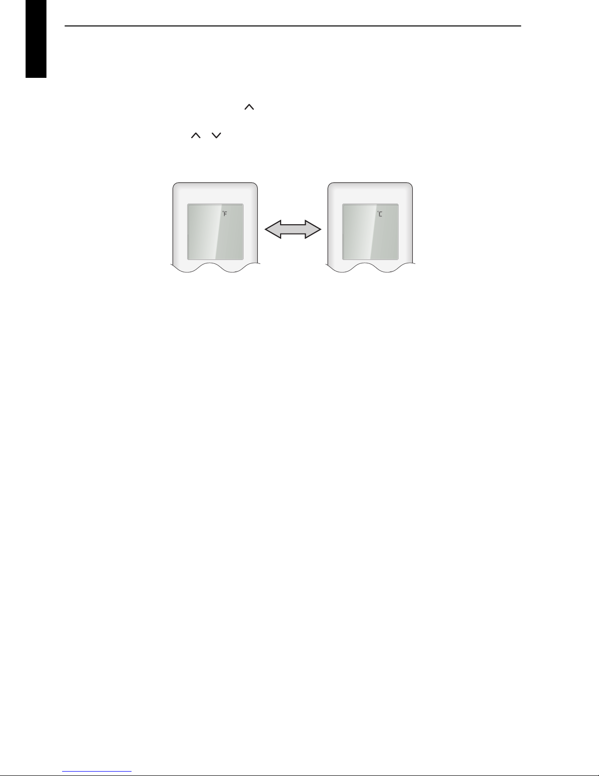
11-3. Switching the temperature unit of remote controller
Displayed temperature unit on the remote controller LCD can be switched between °F (Fahrenheit)
and °C (Celsius).
To change temperature unit, do as follows:
1. Press the TEMP. (Up) button ( ) for at least 5 seconds to display the current temperature
unit. (Factory setting: °F)
2. Press the TEMP. ( ) ( ) buttons to switch the temperature unit between °F and °C.
3. With either of pressing the START/STOP button or no additional button operation for 30
seconds in step 2., the temperature unit currently selected will be set.
Page 39

- 35 -
WALL MOUNTED
ASYG09-14LZCA
12. Accessories
Part name Exterior Q’ty Part name Exterior Q’ty
Operating manual 1 Cloth tape 1
Installation manual 1
Tapping screw (large),
M4 × 25 mm
5
Wall hook bracket 1
Tapping screw (small),
M3 × 12 mm
2
Remote controller 1 Air cleaning filter 2
Battery 2 Filter holder 2
Remote controller
holder
1
Seal A
(for 14 model)
1
Page 40

- 36 -
WALL MOUNTED
ASYG09-14LZCA
13. Optional parts
13-1. Controllers
NOTE: Available functions may differ by the remote controller. For details, refer to the operation
manual.
13-2. Others
Exterior Part name Model name Summary
Wired remote
controller
UTY-RVNYM
Large and full-dot liquid crystal
screen, wide and large keys easy to
press, user-intuitive arrow key.
Wire type: Polar 3-wire
Optional communication kit is
necessary for installation.
Wired remote
controller
UTY-RNNYM
Room temperature can be controlled
by detecting the temperature
accurately with built-in thermo
sensor.
Wire type: Polar 3-wire
Optional communication kit is
necessary for installation.
Simple remote
controller
UTY-RSNYM
Compact remote controller
concentrates on the basic functions
such as Start/Stop, fan control,
temperature setting, and operation
mode.
Wire type: Polar 3-wire
Optional communication kit is
necessary for installation.
Exterior Part name Model name Summary
External
connect kit
UTY-XWZXZ5
Required when external device is
connected.
Optional communication kit is
necessary for installation.
Communication
kit
UTY-TWBXF1
Use to connect with optional devices
and air conditioner PCB.
Page 41

Part 2. OUTDOOR UNIT
SINGLE TYPE:
AOYG09LZCAN
AOYG12LZCAN
AOYG14LZCAN
Page 42
- 38 -
WALL MOUNTED
AOYG09-14LZCAN
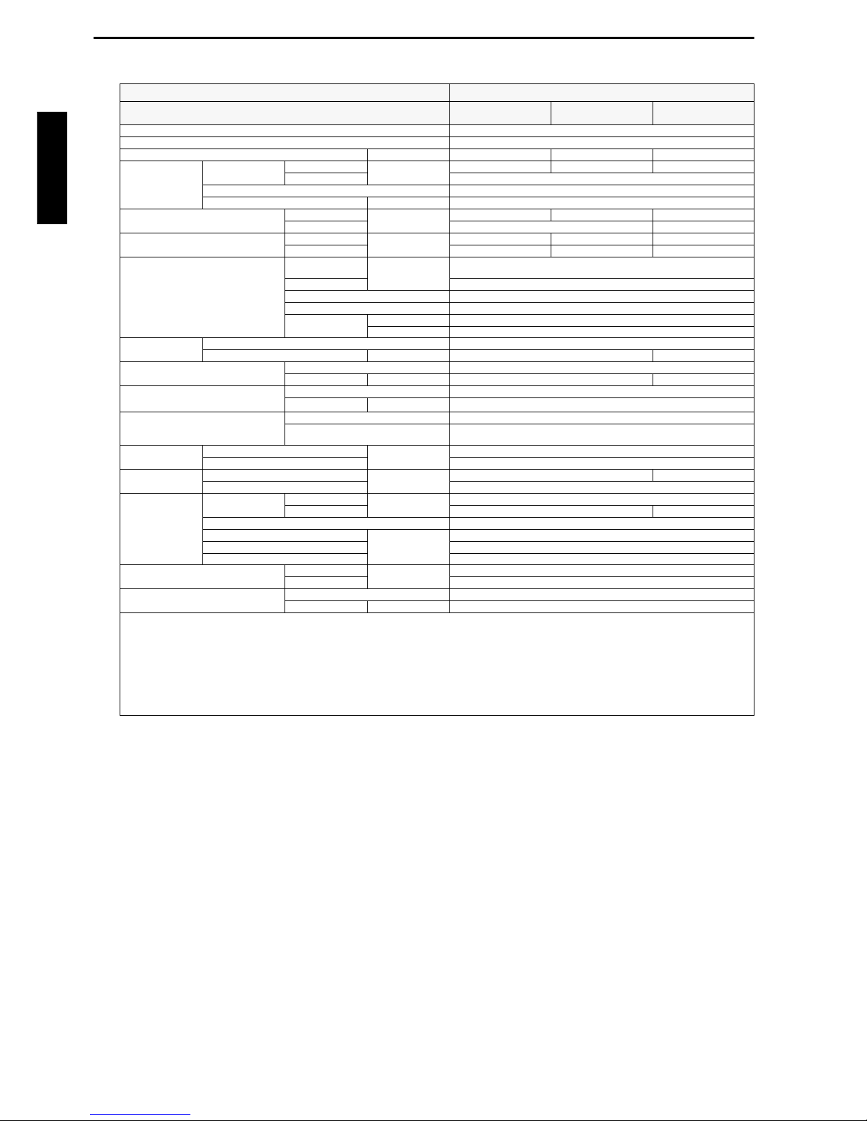
1. Specifications
Typ e Inverter heat pump
Model name
AOYG09LZCAN AOYG12LZCAN AOYG14LZCAN
Power supply 230 V ~ 50 Hz
Available voltage range 198—264 V
Starting current A 2.9 4.0 5.3
Fan
Airflow rate
Cooling
m3/h
1,350 1,680 2,050
Heating 1,840
Type × Q'ty Propeller fan × 1
Motor output W 115
Sound pressure level *1
Cooling
dB (A)
39 43 49
Heating 47 49
Sound power level
Cooling
dB (A)
52 57 61
Heating 58 59 61
Heat exchanger type
Dimensions
(H × W × D)
mm
588 × 881 × 36.4
Fin pitch 1.3
Rows × Stages 2 × 28
Pipe type Copper
Fin type
Type (Material) Corrugate (Aluminum)
Surface treatment Corrosion resistance
Compressor
Type × Q'ty Rotary × 1
Motor output W 850 1,000
Refrigerant
Type (Global warming potential) R410A
Charge g 1,300 1,400
Refrigerant oil
Typ e FREOL α68SZ
Amount
cm
3
350
Enclosure
Material Steel sheet
Color
Beige
Approximate color of MUNSELL 10YR7. 5/1.0
Dimensions
(H × W × D)
Net
mm
620 × 790 × 290
Gross 713 × 945 × 395
Weight
Net
kg
39 40
Gross 43
Connection pipe
Size
Liquid
mm (in)
Ø 6.35 (Ø 1/4)
Gas Ø 9.52 (Ø 3/8) Ø 12.7 (Ø 1/2)
Method Flare
Pre-charge length
m
15
Max. length 20
Max. height difference 15
Operation range
Cooling
°C
-10 to 46
Heating -25 to 24
Drain hose
Material LDPE
Size mm Ø 13.0 (I. D.), Ø 16.0 to Ø 16.7 (O. D.)
NOTES:
• Specifications are based on the following conditions:
– Cooling: Indoor temperature of 27 °CDB/ 19 °CWB, and outdoor temperature of 35 °CDB/ 24 °CWB.
– Heating: Indoor temperature of 20 °CDB/ 15 °CWB, and outdoor temperature of 7 °CDB/ 6 °CWB.
– Pipe length: 5 m, Height difference: 0 m.
• Pro tective function might work when using it outside the operation range.
• *1: Sound pressure level
– Measured values in manufacturer’s anechoic chamber.
– Because of the surrounding sound environment, the sound levels measured in actual installation conditions might be higher than the specified values here.
Page 43

- 39 -
WALL MOUNTED
AOYG09-14LZCAN
2. Dimensions
2-1. Models: AOYG09LZCAN, AOYG12LZCAN, and
AOYG14LZCAN
790
Top view
Front view
Side view
18
62
290
18
20
20
9
110
620
209
352
175
320
4-ø11.3 mm hole
540
Airflow
ø20 hole
Bottom view
(6x20=120) (6x20=120)
25
23
25
23
55
55
(10)
(10)
(10)
20
20
hole
17.5
25
1010
hole
102
Page 44

- 40 -
WALL MOUNTED
AOYG09-14LZCAN
3. Installation space
3-1. Models: AOYG09LZCAN, AOYG12LZCAN, and
AOYG14LZCAN
Space requirement
Provide sufficient installation space for product safety.
Single outdoor unit installation
• When the upper space is open:
• When there is an obstruction in the upper space:
Unit: mm
When there are obstacles at the rear only. When there are obstacles at the rear and sides.
When there are obstacles at the front only. When there are obstacles at the front and rear.
Unit: mm
When there are obstacles at the rear and
above.
When there are obstacles at the rear, sides, and
above.
100 or more
250 or more
100 or more
100 or more
600 or more
600 or more
100 or more
100 or more
Max. 200
600 or more
600 or more
100 or more
250 or more
100 or more
Max. 200
Page 45

- 41 -
WALL MOUNTED
AOYG09-14LZCAN
Multiple outdoor unit installation
• When the upper space is open:
• When there is an obstruction in the upper space:
Unit: mm
When there are obstacles at the rear only. When there are obstacles at the front only.
When there are obstacles at the front and rear.
Unit: mm
When there are obstacles at the rear and above.
200
or more
1,000 or more
200 or more
1,000 or more
1,500 or more
200 or more
Max. 300
Page 46
- 42 -
WALL MOUNTED
AOYG09-14LZCAN
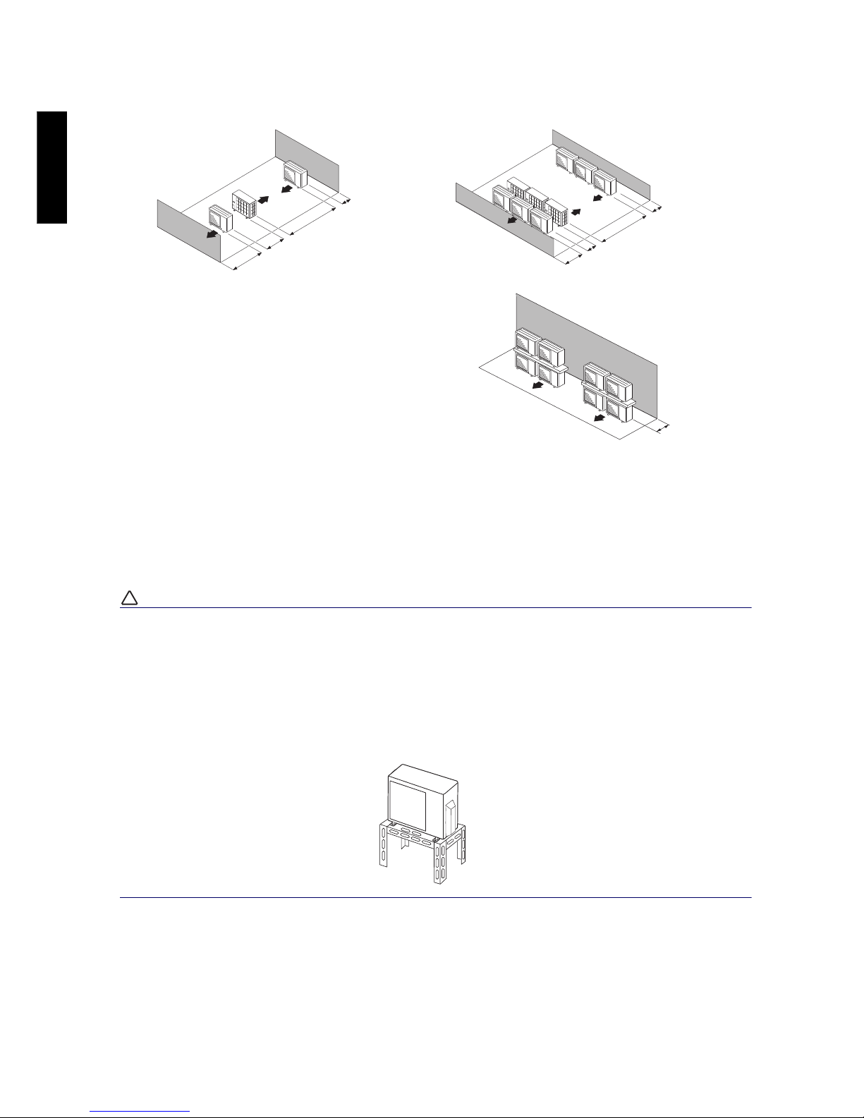
Outdoor unit installation in multi-row
NOTES:
• If the space is larger than stated above, the condition will be the same as when there is no
obstacle.
• Height above the floor level should be 50 mm or more.
• When installing the outdoor unit, be sure to open the front and left side to obtain better operation
efficiency.
!
CAUTION
• Do not install the outdoor unit in two-stage where the drain water could freeze. Otherwise the
drainage from the upper unit may form ice and cause a malfunction of the lower unit.
• When the outdoor temperature is 0 °C or less, do not use the accessory drain pipe and drain cap.
If the drain pipe and drain cap are used, the drain water in the pipe may freeze in extremely cold
climate. (For reverse cycle model only.)
• In area with heavy snowfall, if the inlet and outlet of the outdoor unit is blocked with snow, it might
become difficult to get warm, and it is likely to cause product malfunction. Construct a canopy and
a pedestal, or place the unit on a high stand that is locally installed.
Unit: mm
Single parallel unit arrangement Multiple parallel unit arrangement
100 or more
200 or more
500 or more
1,000 or more
200 or more
400 or more
1,000 or more
2,000 or more
200 or more
Page 47

- 43 -
WALL MOUNTED
AOYG09-14LZCAN
4. Refrigerant circuit
4-1. Models: AOYG09LZCAN and AOYG12LZCAN
2-way
valve
Strainer
Strainer
3-way
valve
MufflerMuffler
Acccumlator
4-way valve
Expansion valve
Heat exchanger
( INDOOR )
Heat exchanger
( OUTDOOR )
Compressor
Cooling
Heating
Th
D
Th
R
Th
PI
Th
HO
Th
O
Th
R
Th
PI
Th
D
Th
O
Th
HO
:Thermistor (Room temp.)
:Thermistor (Pipe temp.)
:Thermistor (Discharge temp.)
:Thermistor (Outdoor temp.)
:Thermistor (Heat exchanger out temp.)
Page 48

- 44 -
WALL MOUNTED
AOYG09-14LZCAN
4-2. Model: AOYG14LZCAN
Th
R
Th
PI
Th
R
Th
PI
Th
D
Th
D
Th
O
Th
HO
: Thermistor (Room temp.)
: Thermistor (Pipe temp.)
: Thermistor (Discharge temp.)
: Thermistor (Outdoor temp.)
: Thermistor (Heat exchanger out temp.)
Th
O
Th
HO
Compressor
Muffler
Muffler
Heat exchanger
(INDOOR)
Heat exchanger
(OUTDOOR)
3-Way
valve
2-Way
valve
Cooling
Heating
Receiver
Strainer
Strainer
Expansion valve
Page 49

- 45 -
WALL MOUNTED
AOYG09-14LZCAN
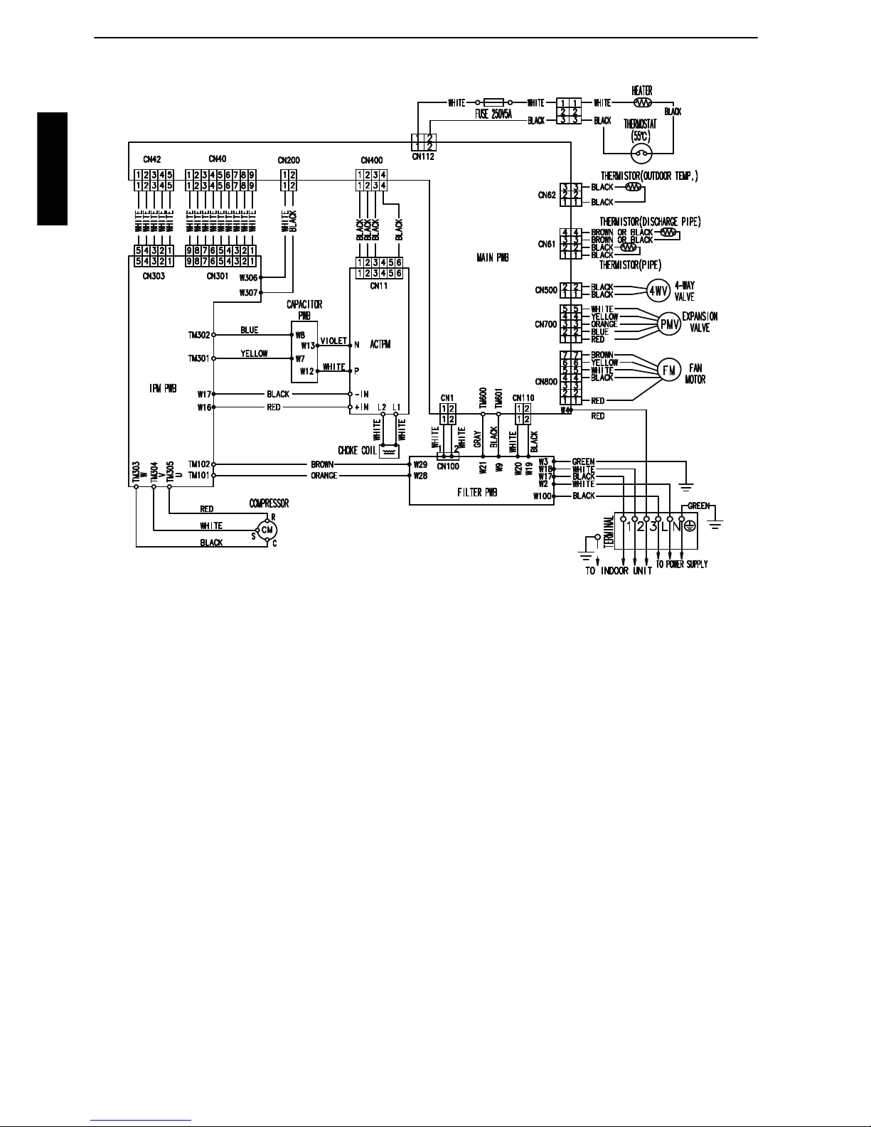
5. Wiring diagrams
5-1. Models: AOYG09LZCAN and AOYG12LZCAN
Page 50
- 46 -
WALL MOUNTED
AOYG09-14LZCAN
5-2. Model: AOYG14LZCAN
Page 51

- 47 -
WALL MOUNTED
AOYG09-14LZCAN
6. Capacity compensation rate for pipe length and height
difference
6-1. Models: AOYG09LZCAN and AOYG12LZCAN
NOTE: Values mentioned in the table are calculated based on the maximum capacity.
COOLING
Pipe length (m)
5 7.5 10 15 20
Height difference H (m)
Indoor unit is higher than
outdoor unit *1
15 - - - 0.877 0.874
10 - - 0.956 0.891 0.888
7.5 - 0.988 0.960 0.895 0.892
5 1.017 0.992 0.964 0.899 0.895
0 1.025 1.000 0.971 0.906 0.902
Indoor unit is lower than
outdoor unit *2
-5 1.025 1.000 0.971 0.906 0.902
-7.5 - 1.000 0.971 0.906 0.902
-10 - - 0.971 0.906 0.902
-15 - - - 0.906 0.902
HEATING
Pipe length (m)
5 7.5 10 15 20
Height difference H (m)
Indoor unit is higher than
outdoor unit *1
15 - - - 0.933 0.925
10 - - 0.981 0.933 0.925
7.5 - 1.000 0.981 0.933 0.925
5 1.017 1.000 0.981 0.933 0.925
0 1.017 1.000 0.981 0.933 0.925
Indoor unit is lower than
outdoor unit *2
-5 1.012 0.995 0.976 0.928 0.920
-7.5 - 0.993 0.974 0.926 0.918
-10 - - 0.971 0.923 0.916
-15 - - - 0.914 0.906
Height difference H
Indoor unit is higher than outdoor unit
*
1
Indoor unit is lower than outdoor unit *
2
Indoor unit
Indoor unit
Connection pipe
Outdoor unit
Outdoor unit
Connection pipe
HH
Page 52

- 48 -
WALL MOUNTED
AOYG09-14LZCAN
6-2. Model: AOYG14LZCAN
NOTE: Values mentioned in the table are calculated based on the maximum capacity.
COOLING
Pipe length (m)
5 7.5 10 15 20
Height difference H (m)
Indoor unit is higher than
outdoor unit *1
15 - - - 0.951 0.950
10 - - 0.979 0.967 0.966
7.5 - 0.988 0.983 0.971 0.970
5 0.994 0.992 0.987 0.975 0.974
0 1.002 1.000 0.995 0.983 0.982
Indoor unit is lower than
outdoor unit *2
-5 1.002 1.000 0.995 0.983 0.982
-7.5 - 1.000 0.995 0.983 0.982
-10 - - 0.995 0.983 0.982
-15 - - - 0.983 0.982
HEATING
Pipe length (m)
5 7.5 10 15 20
Height difference H (m)
Indoor unit is higher than
outdoor unit *1
15 - - - 0.994 0.979
10 - - 1.012 0.994 0.979
7.5 - 1.000 1.012 0.994 0.979
5 0.969 1.000 1.012 0.994 0.979
0 0.969 1.000 1.012 0.994 0.979
Indoor unit is lower than
outdoor unit *2
-5 0.964 0.995 1.007 0.989 0.974
-7.5 - 0.993 1.004 0.986 0.972
-10 - - 1.002 0.984 0.969
-15 - - - 0.974 0.959
Page 53

- 49 -
WALL MOUNTED
AOYG09-14LZCAN
7. Additional charge calculation
7-1. Models: AOYG09LZCAN and AOYG12LZCAN
Refrigerant charge
7-2. Model: AOYG14LZCAN
Refrigerant charge
Refrigerant type R410A
Refrigerant amount g 1,300
Total pipe length m 15 or less 20 (Max.)
20 g/m
Additional charge g 0 100
Refrigerant type R410A
Refrigerant amount g 1,400
Total pipe length m 15 or less 20 (Max.)
20 g/m
Additional charge g 0 100
Page 54

- 50 -
WALL MOUNTED
AOYG09-14LZCAN
8. Airflow
8-1. Model: AOYG09LZCAN
Cooling
Heating
8-2. Model: AOYG12LZCAN
Cooling
Heating
8-3. Model: AOYG14LZCAN
Cooling
Heating
m3/h
1,350
l/s 375
CFM 795
m
3
/h
1,840
l/s 511
CFM 1083
m
3
/h
1,680
l/s 467
CFM 989
m
3
/h
1,840
l/s 511
CFM 1083
m
3
/h
2,050
l/s 569
CFM 1206
m3/h
1,840
l/s 511
CFM 1083
Page 55

- 51 -
WALL MOUNTED
AOYG09-14LZCAN
9. Operation noise (sound pressure)
9-1. Noise level curve
Model: AOYG09LZCAN
Cooling Heating
Model: AOYG12LZCAN
Cooling Heating
NC-65
NC-60
NC-55
NC-50
NC-45
NC-40
NC-35
NC-30
NC-25
NC-20
NC-15
Octave band sound pressure level, dB: (0 dB=0.0002 µbar)
Octave band center frequency, Hz
80
70
60
50
40
30
20
10
0
63 125 250 500 1,000 2,000 4,000 8,000
NC-65
NC-60
NC-55
NC-50
NC-45
NC-40
NC-35
NC-30
NC-25
NC-20
NC-15
Octave band sound pressure level, dB: (0 dB=0.0002 µbar)
Octave band center frequency, Hz
80
70
60
50
40
30
20
10
0
63 125 250 500 1,000 2,000 4,000 8,000
NC-65
NC-60
NC-55
NC-50
NC-45
NC-40
NC-35
NC-30
NC-25
NC-20
NC-15
Octave band sound pressure level, dB: (0 dB=0.0002 µbar)
Octave band center frequency, Hz
80
70
60
50
40
30
20
10
0
63 125 250 500 1,000 2,000 4,000 8,000
NC-65
NC-60
NC-55
NC-50
NC-45
NC-40
NC-35
NC-30
NC-25
NC-20
NC-15
Octave band sound pressure level, dB: (0 dB=0.0002 µbar)
Octave band center frequency, Hz
80
70
60
50
40
30
20
10
0
63 125 250 500 1,000 2,000 4,000 8,000
Page 56

- 52 -
WALL MOUNTED
AOYG09-14LZCAN
Model: AOYG14LZCAN
Cooling Heating
NC-65
NC-60
NC-55
NC-50
NC-45
NC-40
NC-35
NC-30
NC-25
NC-20
NC-15
Octave band sound pressure level, dB: (0 dB=0.0002 µbar)
Octave band center frequency, Hz
80
70
60
50
40
30
20
10
0
63 125 250 500 1,000 2,000 4,000 8,000
NC-65
NC-60
NC-55
NC-50
NC-45
NC-40
NC-35
NC-30
NC-25
NC-20
NC-15
Octave band sound pressure level, dB: (0 dB= 0.0002 µbar)
Octave band center frequency, Hz
80
70
60
50
40
30
20
10
0
63 125 250 500 1,000 2,000 4,000 8,000
Page 57

- 53 -
WALL MOUNTED
AOYG09-14LZCAN
9-2. Sound level check point
NOTE: Detailed shape of the actual outdoor unit might be slightly different from the one illustrated
above.
1 m
MicrophoneMicrophone
Rear
Airflow
Rear view
Side view
Page 58

- 54 -
WALL MOUNTED
AOYG09-14LZCAN
10. Electrical characteristics
*1: Maximum current is the total current of the indoor unit and the outdoor unit.
*2: Selected sample based on Japan Electrotechnical Standards and Codes Committee E0005. As
the regulations of wire size and circuit breaker differ in each country or region, select appropriate
devices complied to the regional standard.
*3: Limit voltage drop to less than 2%. If voltage drop is 2% or more, increase cable conductor size.
Model name AOYG09LZCAN AOYG12LZCAN AOYG14LZCAN
Power
supply
Voltage V 230~
Frequency Hz 50
Max operating current *1 A 11.9 14.9
Starting current A 2.9 4.0 5.3
Wiring
spec. *2
Circuit breaker current A 15 20
Power cable
mm
2
1.5 3.5—4.0
Connection cable *3
mm
2
1.5
Limited wiring length m 21
Page 59

- 55 -
WALL MOUNTED
AOYG09-14LZCAN
11. Safety devices
Type of
protection
Protection form
Model
AOYG09LZCAN AOYG12LZCAN AOYG14LZCAN
Circuit protection
Current fuse (Near the terminal)
250 V, 20 A
250 V, 5 A
250 V, 5 A
Current fuse (Filter PCB) —
250 V, 20 A
250 V, 5 A
Current fuse (Main PCB)
250 V, 15 A 250 V, 5 A
250 V, 3.15 A 250 V, 3.15 A
Fan motor
protection
Thermal protection
program
Activate
110±15 °C
Fan motor stop
Reset
95±10 °C
Fan motor restart
Compressor
protection
Thermal protection
program
(Discharge temp.)
Activate
110 ° C
Compressor stop
Reset
After 7 minutes
Compressor restart
Page 60

- 56 -
WALL MOUNTED
AOYG09-14LZCAN
12. Accessories
Part name Exterior Q’ty Part name Exterior Q’ty
Installation manual 1
 Loading...