

Page 1

SPLIT TYPE
AIR CONDITIONER
CASSETTE TYPE (50Hz)
Indoor unit Outdoor unit
AUYG12LVLB
AUYG14LVLB
AUYG18LVLB
AOYG12LALL
AOYG14LALL
AOYG18LALL
C O N T E N T S
SPECIFICATIONS . . . . . . . . . . . . . . . . . .
1
DIMENSIONS. . . . . . . . . . . . . . . . . . . . . .
2
REFRIGERANT SYSTEM DIAGRAM . . .
4
ERROR DETECTION . . . . . . . . . . . . . . .
6
CIRCUIT DIAGRAM. . . . . . . . . . . . . . . . .
5
INDOOR PCB CIRCUIT DIAGRAM . . . . .
10
OUTDOOR PCB CIRCUIT DIAGRAM
. . .
12
PARTS (DECORATION PANEL) . . . . . .
14
PARTS (INDOOR UNIT). . . . . . . . . . . . .
16
PARTS (OUTDOOR UNIT) . . . . . . . . . . .
19
ACCESSORIES . . . . . . . . . . . . . . . . . . .
21
Page 2
12011.12.12
S P E C I F I C AT I O N S
TYPE
DECORATION PANEL
INDOOR UNIT
OUTDOOR UNIT
COOLING CAPACITY
HEATING CAPACITY
POWER SOURCE
RUNNING
CURRENT
MAXIMUM
CURRENT
Cooling
Heating
INPUT
WATTS
Cooling
Heating
E.E.R.
COP
Cooling
Heating
Cooling
Heating
Cooling
Heating
MOISTURE REMOVAL
AIR
CIRCULATION
(HIGH)
ELECTRICAL DATA
FAN MOTOR
DIMENSIONS
INDOOR UNIT, Discrimination
INDOOR UNIT
(cool)
High
Medium
Low
730 r.p.m.
630 r.p.m.
540 r.p.m.
Quiet
460 r.p.m.
650 r.p.m.
580 r.p.m.
520 r.p.m.
460 r.p.m.
OUTDOOR UNIT (heat)
INDOOR UNIT
245 x 570 x 570 mm
OUTDOOR UNIT
H x W x D
H x W x D
H x W x D
PANEL 49 x 700 x 700 mm
WEIGHT
INDOOR UNIT
15 kg / 18 kg
OUTDOOR UNIT
Net / Shipping
Net / Shipping
Net / Shipping
PANEL
1.2 L/hr
AUYG12LVLB AUYG14LVLB
AOYG12LALL AOYG14LALL
3.50 kW
4.10 kW
4.30 kW
5.00 kW
4.8 A
5.1 A
1.05 kW
1.11 kW
3.33 kW/kW
3.69 kW/kW
230 V, 50 Hz
1.5 L/hr
600 m3/hr 680 m3/hr
6.1 A
6.1 A
1.33 kW
1.34 kW
3.21 kW/kW
3.71 kW/kW
MFF-24RVL
OUTDOOR UNIT, Discrimination
MFE-63NOM
700 r.p.m. 750 r.p.m.
578 x 790 x 300 mm
40 kg / 44 kg
COMPRESSOR AND REFRIGERANT
NOISE LEVEL
High 37 dB
10.0 A
INDOOR UNIT
(cool)
Medium
34 dB
Low 30 dB
Quiet 27 dB
OUTDOOR UNIT (heat)
48 dB
38 dB
34 dB
30 dB
27 dB
49 dB
Pipe length
15 m 1,150 g
FULL
CHARGE
COMPRESSOR
WEIGHT (with oil)
REFRIGERANT TYPE
20 m 1,250 g
ADDITIONAL CHARGE
MAXIMUM PIPING HEIGHT
PRECHARGED
1,250 g
DA130A1F-25NA
1,350 g
25 m 1,350 g 1,450 g
20 g/m
15 m
730 r.p.m.
630 r.p.m.
540 r.p.m.
460 r.p.m.
INDOOR UNIT
(heat)
High
Medium
Low
830 r.p.m.
730 r.p.m.
630 r.p.m.
Quiet 500 r.p.m.
650 r.p.m.
580 r.p.m.
520 r.p.m.
460 r.p.m.
830 r.p.m.
730 r.p.m.
630 r.p.m.
500 r.p.m.
2.6 kg / 4.5 kg
2.2 L/hr
Inverter cooling & heating
UTG-UFYD-W
AUYG18LVLB
AOYG18LALL
5.20 kW
6.00 kW
7.2 A
7.4 A
1.62 kW
1.66 kW
3.21 kW/kW
3.61 kW/kW
680 m3/hr
600 m3/hr 800 m3/hr 680 m3/hr
820 r.p.m.
OUTDOOR UNIT (cool)
770 r.p.m. 820 r.p.m. 860 r.p.m.
38 dB
34 dB
30 dB
26 dB
High 37 dB
INDOOR UNIT
(heat)
Medium
34 dB
Low 31 dB
Quiet 29 dB
43 dB
38 dB
34 dB
30 dB
43 dB
38 dB
34 dB
30 dB
50 dB
OUTDOOR UNIT (cool)
47 dB 49 dB 50 dB
1,250 g
1,150 g 1,250 g 1,250 g
1,350 g
1,450 g
12.5 A 12.5 A
7.5 A 9.0 A 9.0 A
9.6 kg
R410A
Page 3
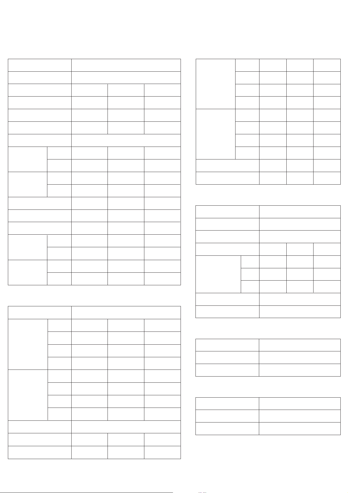
INDOOR UNIT DECORATION PANEL
D I ME N S I O N S
2011.12.12 2
Unit : mm
530 : Hanging bolt position
102
135 250
700
700
75
30
30
262
540 : Hanging bolt position
Ceiling openings
Decoration panel mounting state
150 to 200Min. 450
Min. 450
Maintenance space
215
123
58
114
146
108
102
245
30
40 99
Drain port
Ceiling
Drain port
Be sure to leave
maintenance space
for future service
at the designated
position.
30
49
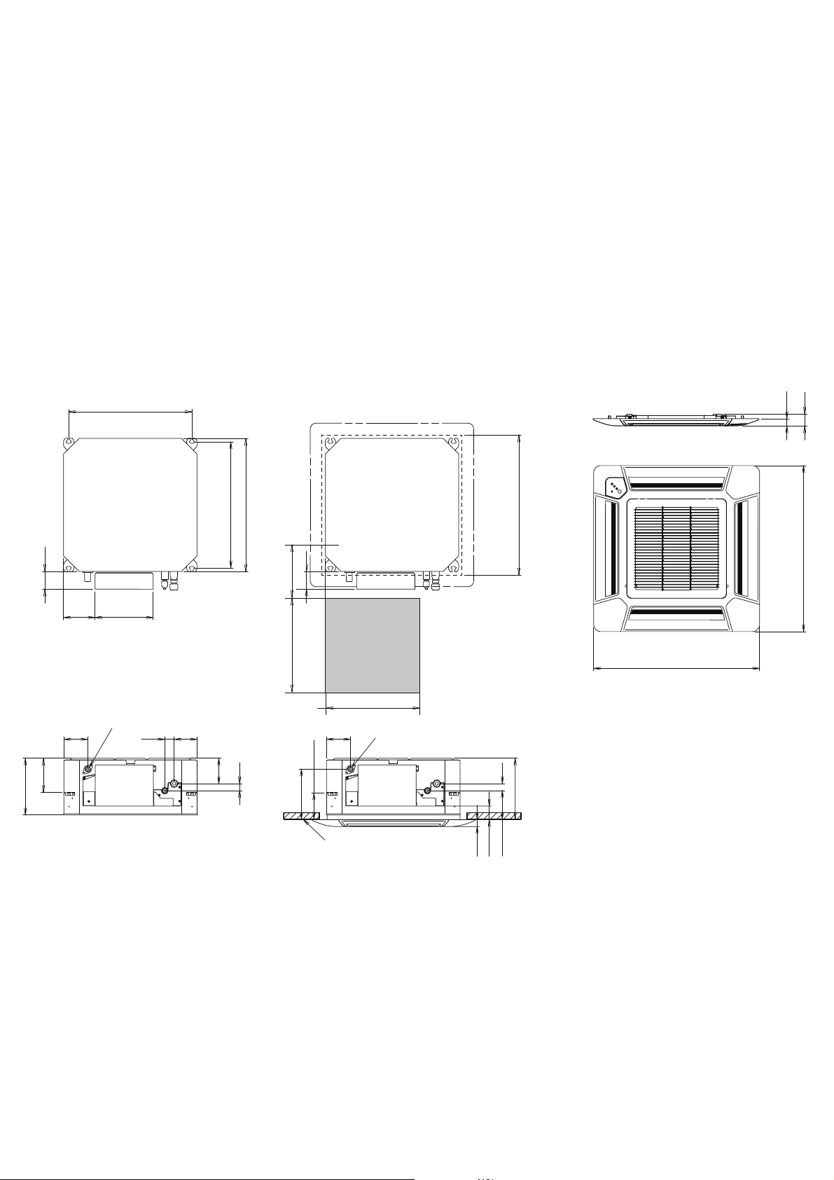
Page 4
OUTDOOR UNIT
Unit : mm
347
540
300
66
790
578
320
10
Air flow
2011.12.12
3
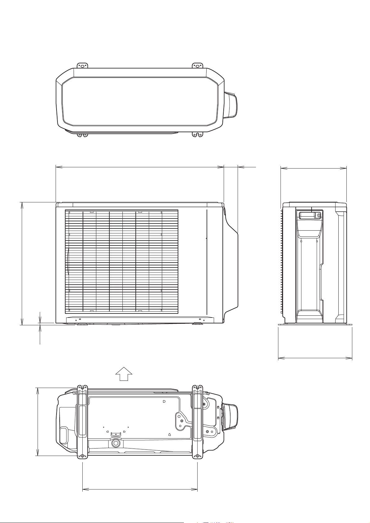
Page 5
R E FR I G E R A N T S Y S T E M D I A G R A M
OUTDOOR UNIT INDOOR UNIT
2011.12.18
StrainerStrainer
4-way
valve
2-way
valve
3-way
valve
Muffler
Muffler
Expansion
valve
Compressor
Accumulator
Heat
exchanger
Heat
exchanger
Cooling
<Refrigerant direction>
Heating
: Compressor thermistor
: Pipe thermistor
: Room thermistor
: Discharge pipe thermistor
: Heat exchanger thermistor (Middle)
: Heat exchanger thermistor (Out)
: Outdoor thermistor
<Refrigerant pipe diameter>
12
Liquid : 1/4" (6.35 mm)
Gas : 3/8" (9.52 mm)
14, 18
Liquid : 1/4" (6.35 mm)
Gas : 1/2" (12.70 mm)
4
Page 6
COMPRESSOR
W7
W8
W9
CM
R(R)
S(S)
C(T)
RED
WHITE
BLACK
RED
BLACK
WHITE
YELLOW
BLUE
RED
BROWN
BLUE
ORANGE
YELLOW
WHITE
BLACK
BLACK
BLACK
WHITE
BLACK
BLACK
BLACK
BLACK
BLACK
RED
WHITE
BLACK
BLACK
BROWN
BROWN
BROWN
BROWN
BLACK
BLACK
RED
WHITE
GREEN
W10
W11
CN71
CN73
CN72
CN70
W4
W2
W1
W3
CN800
CN40
CN30
FM
PMV
FAN MOTOR
EXPANSION
VALVE
4-WAY VALVE
4WV
FUSE
20A
250V
FUSE
5A
250V
TERMINAL
THERMISTOR
( OUTDOOR TEMP. )
THERMISTOR
( PIPE - M I D. TEMP. )
THERMISTOR
( COMP. TEMP. )
THERMISTOR
( DISCHARGE TEMP. )
THERMISTOR
( PIPE TEMP. )
REACTOR
CONTROLLER
PCB ASSY
1 2
(N)
3LN
POWER SOURCE
1
2
3
4
5
6
7
1
2
3
4
5
6
1
2
3
4
5
6
1
2
3
1
2
3
1
2
3
4
1
2
1
2
1
2
3
1
2
3
4
1
2
1
2
1
2
3
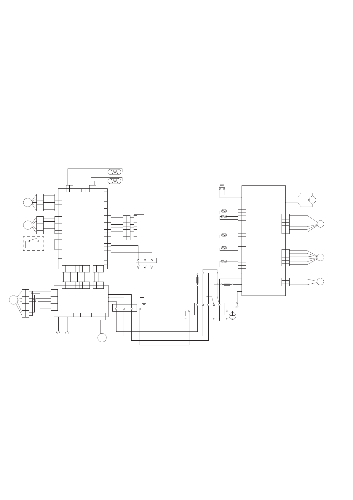
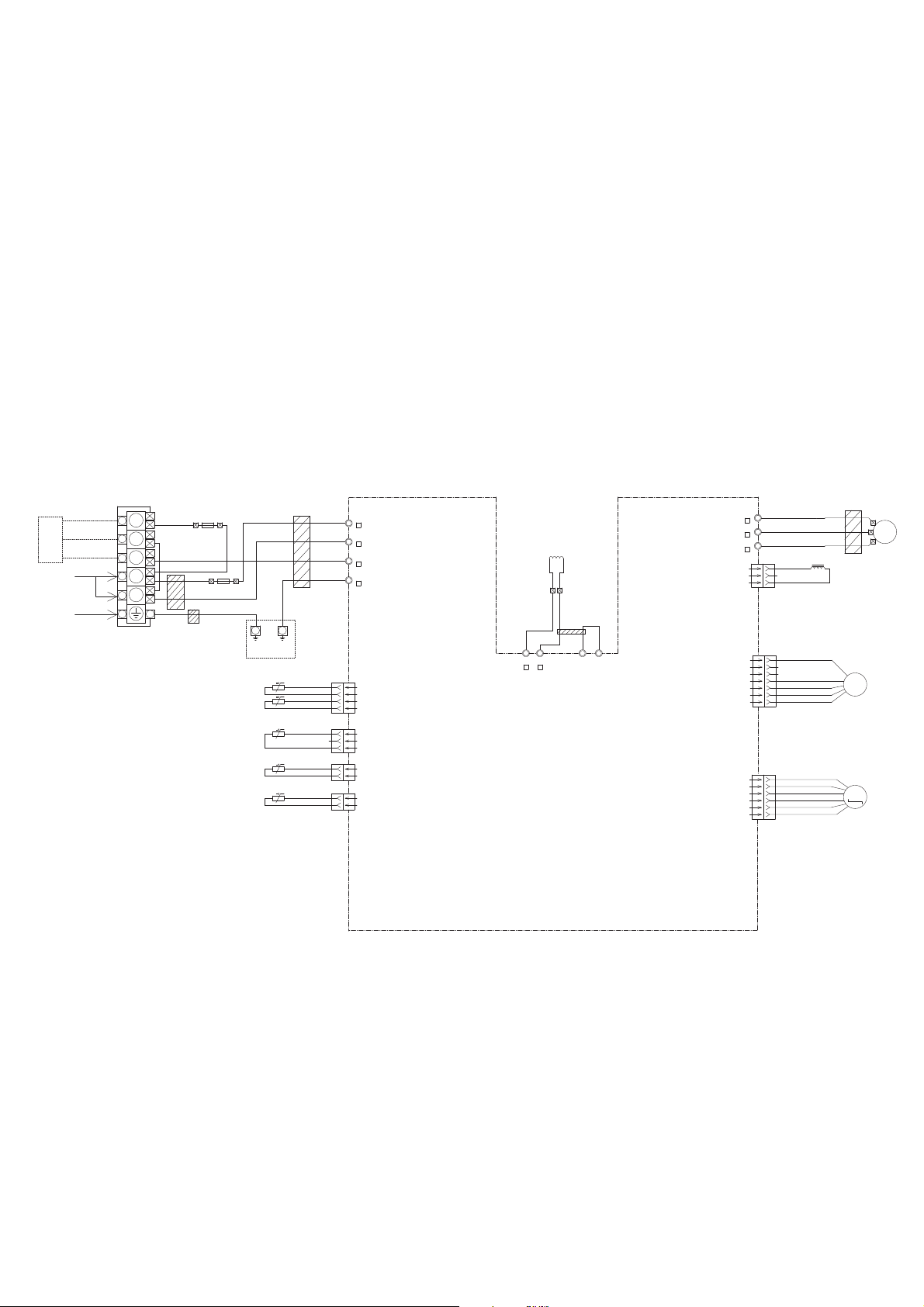
INDOOR UNIT OUTDOOR UNIT
C I R C U I T D I AG R A M
2011.11.14 5
GRAY
GRAY
GRAY
GRAY
GRAY
GRAY
GRAY
GRAY
GRAY
GRAY
GRAY
BROWN
RED
ORANGE
YELLOW
WHITE
BLUE
PURPLE
RED
WHITE
BLACK
RED
WHITE
BLACK
BLACK
GRAY
BLACK
GRAY
RED
ORANGE
YELLOW
PINK
BLUE
RED
ORANGE
YELLOW
PINK
BLUE
BLACK
BLACK
BROWN
YELLOW
WHITE
BLACK
RED
GREEN
GREEN
YELLOW
YELLOW
1 2
3 4 567 8
1 2
3 4 567 8
1 2
3 4 567 8
1 2
3 4 567 8
1 2
3
1 2
3
1 2
3
1 2
3
1 2
1 2
1 2 1 2
1 2
1 231 2 1 2
1 2
1
2
3
4
5
6
7
8
1
2
3
4
5
6
7
8
1
2
3
4
5
1
2
3
4
5
1
2
3
4
5
1
2
3
4
5
1
2
3
4
5
1
2
3
4
5
1
2
3
4
5
1
2
3
4
5
1
2
3
1
2
3
1
2
1
2
3
4
5
6
1
2
3
4
5
6
1
2
3
4
5
6
1
2
3
4
5
6
7
1
2
3
4
5
6
7
1
2
3
4
5
6
7
1
2
3
4
5
6
7
1
2
3
4
5
6
7
1
2
3
1
2
1
2
3
CN5 CN7
CN8
CN4 CN1
CN6
CN14
CN13
CN3
CN12
CN11
CN9
CN10
CN104
CN101
W105
W102
W101
CN105
CN103
CN106
E101 E102
THERMISTOR
( PIPE TEMP. )
THERMISTOR
( ROOM TEMP. )
TERMINAL
TERMINAL
WIRED REMOTE
CONTROL ( OPTION )
FRESH AIR
( OPTION )
M
DRAIN
PUMP
MOTOR
FAN MOTOR
FM
INDICATOR
PCB ASSY
FLOAT SWITCH
M
M
EX I N ( OPTION )
EX OUT ( OPTION )
1
2
3
1
2 3
CONTROLLER
PCB ASSY
( MAIN PCB )
POWER SUPPLY
PCB ASSY
LOUVER
( UP / DOWN )
LOUVER
( RIGHT / LEFT )
Page 7
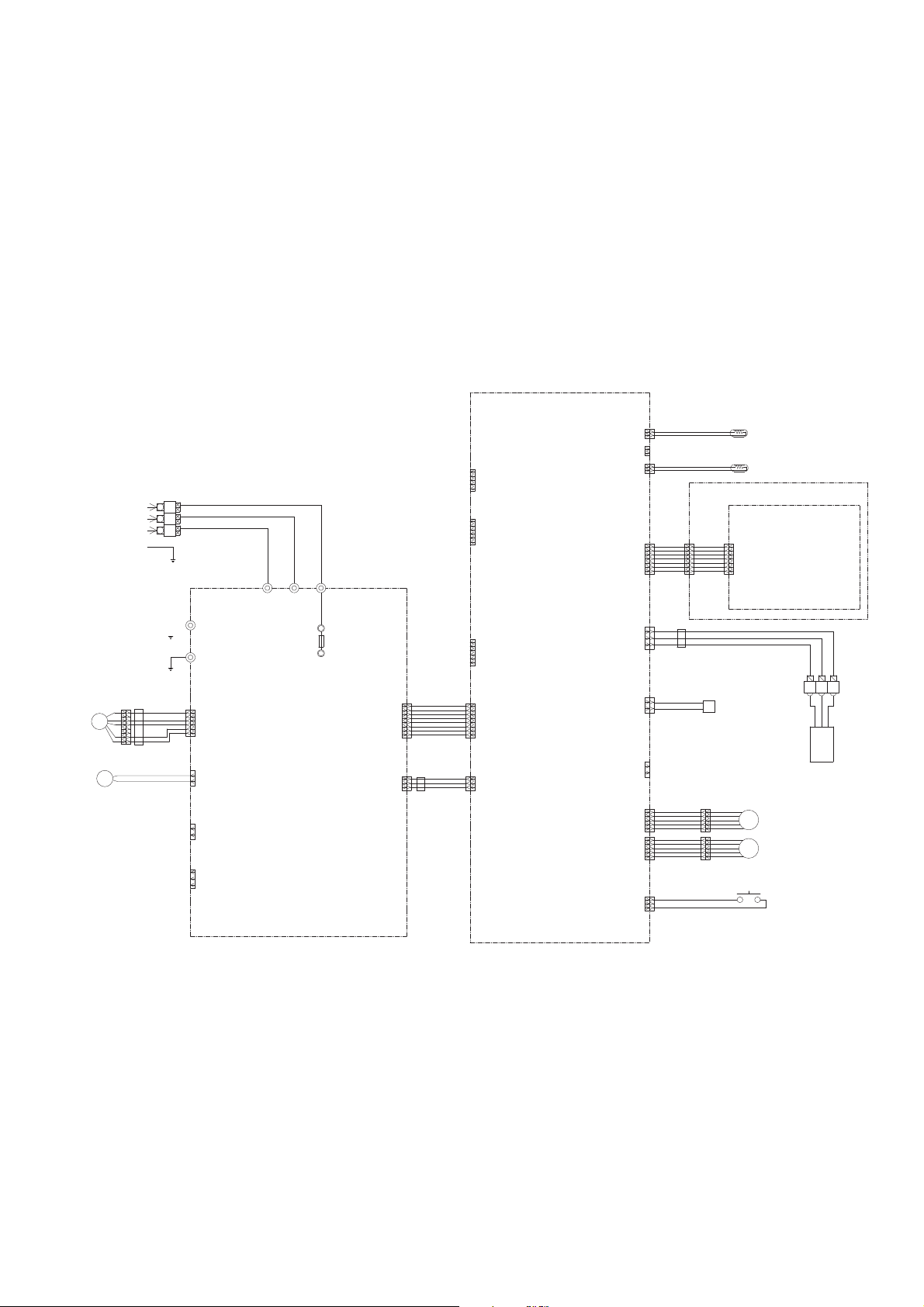
FLOAT SWITCH
LOUVER ( RIGHT / LEFT )
LOUVER ( UP / DOWN )
WIRED REMOTE CONTROL
TERMINAL
HP-T3031-21
FRESH AIR
( OPTION )
JUNCTION
CONNECTOR
XMR-07V
WHITE
UL1430 AWG28
x 7
UL1430 AWG28
x 7
BROWN
RED
ORANGE
YELLOW
GREEN
BLUE
PURPLE
BROWN
RED
ORANGE
YELLOW
GREEN
BLUE
PURPLE
1
2
3
4
5
6
7
1
2
3
4
5
6
7
CN201-1
CN201-2
CN201-3
CN201-4
CN201-5
CN201-6
CN201-7
CN13-1
CN13-2
CN13-3
CN13-4
CN13-5
CN13-6
CN13-7
GRAY
GRAY
BLACK
BLACK
CN5-1
CN5-2
CN7-1
CN7-2
CN8-1
CN8-2
CN14-1
CN14-2
CN14-3
CN6-1
CN6-2
CN10-1
CN10-2
CN11-1
CN11-2
CN11-3
CN11-4
CN11-5
CN12-1
CN12-2
CN12-3
CN12-4
CN12-5
CN9-1
CN9-2
CN9-3
CN2-1
CN2-2
CN2-3
CN2-4
CN2-5
CN15-1
CN15-2
CN15-3
CN15-4
CN15-5
CN15-6
CN3-1
CN3-2
CN3-3
CN3-5
CN3-6
CN3-4
CN4-1
CN4-2
CN4-3
CN4-4
CN4-5
CN4-6
CN4-7
CN4-8
CN1-1
CN1-2
CN1-3
CN104-1
CN104-2
CN104-3
CN104-4
CN104-5
CN104-6
CN104-7
CN104-8
CN101-1
CN101-2
CN101-3
CN105-6
CN105-5
CN105-4
CN105-3
CN105-2
CN105-1
CN106-1
CN106-2
CN103-1
CN103-2
CN102-1
CN102-2
CN102-3
1
2
3
4
5
6
7
8
UL1015 AWG22 x 5
RED
BLACK
WHITE
YELLOW
BROWN
UL1015 AWG18 YELLOW
UL1015 AWG18 YELLOW
UL1015
AWG16
GREEN
UL1015
AWG16
GREEN
TERMINAL
HP-T3031-3-L1
UL1015
AWG20
BLACK
UL1015
AWG20
WHITE
UL1015
AWG20
RED
W105
W102
W101
F101
AC250V
3.15A
E101
E102
UL1430 AWG26 x 3
GRAY
UL1430 AWG26 x 8
GRAY
GRAY
GRAY
GRAY
GRAY
GRAY
GRAY
GRAY
GRAY
GRAY
UL1430 AWG26 x 5
UL1430 AWG26 x 5
RED
ORANGE
YELLOW
PINK
BLUE
RED
ORANGE
YELLOW
PINK
BLUE
RED
ORANGE
YELLOW
PINK
BLUE
RED
ORANGE
YELLOW
PINK
BLUE
UL1007 AWG24 BLACK
UL1007 AWG24 BLACK
UL1430 AWG22 WHITE
UL1430 AWG22 BLACK
UL1430 AWG22 RED
BLK WHT RED
THERMISTOR
( ROOM TEMPERATURE )
THERMISTOR
(PIPE - MID. TEMPERATURE )
CN201
S07B-PASK-2
WHITE
TEST
CN2
B5P-SHF-1AA
WHITE
CN15
B06B-XASK-1-A
WHITE
CN3
B06B-PASK-1
WHITE
POWER DRIVE
DC SUPPLY
CN4
B08B-PASK-1
WHITE
CN1
B03B-PASK-1
WHITE
CN105
B5P6-VH-B
WHITE
CN106
B2P3-VH-B-E
BLUE
EXTERNAL OUTPUT
EXTERNAL I NPUT
CN103
B2B-XH-AM
WHITE
CN102
B5P6-VH-B
WHITE
CN101
B03B-PASK-1
WHITE
CN104
B08B-PASK-1
WHITE
CN8
B02B-XASK-1-A
WHITE
CN7
B02B-XAYK-1-A
YELLOW
CN5
B02B-XAKK-1-A
BLACK
CN13
B07B-PASK-1
WHITE
CN14
B03B-XAKK-1-A
BLACK
CN6
B02B-PAMK-1
GREEN
CN10
B02B-PAOK-1
ORANGE
CN11
B05B-XASK-1-A
WHITE
CN12
B05B-XARK-1-A
RED
CN9
B03B-XARK-1-A
RED
DC FAN MOTOR
DRAIN PUMP
M
F M
M
M
L
N
SERIAL
E
1
2
3
POWER SOURCE
AC230V
50Hz
EMI FILTER
ZCAT2132-1130
1 T
EMI FILTER
ZCAT1518-0730
1 T
EMI FILTER
ZCAT1518-0730
2 T
INDICATOR PCB ASSEMBLY
K06AG-1000HSE-D0
DECORATION PANEL ASSEMBLY
POWER SUPPLY PCB ASSEMBLY
K06AL-1007HSE-P0
CONTROLLER PCB ASSEMBLY
( MAIN PCB )
AUYG12LVLB : K06AK-1104HSE-C1
AUYG14LVLB : K06AK-1105HSE-C1
AUYG18LVLB : K06AK-1106HSE-C1
CONTROL UNIT
AUYG12LVLB : EZ-01113HSE
AUYG14LVLB : EZ-01114HSE
AUYG18LVLB : EZ-01115HSE
2011.11.14 6
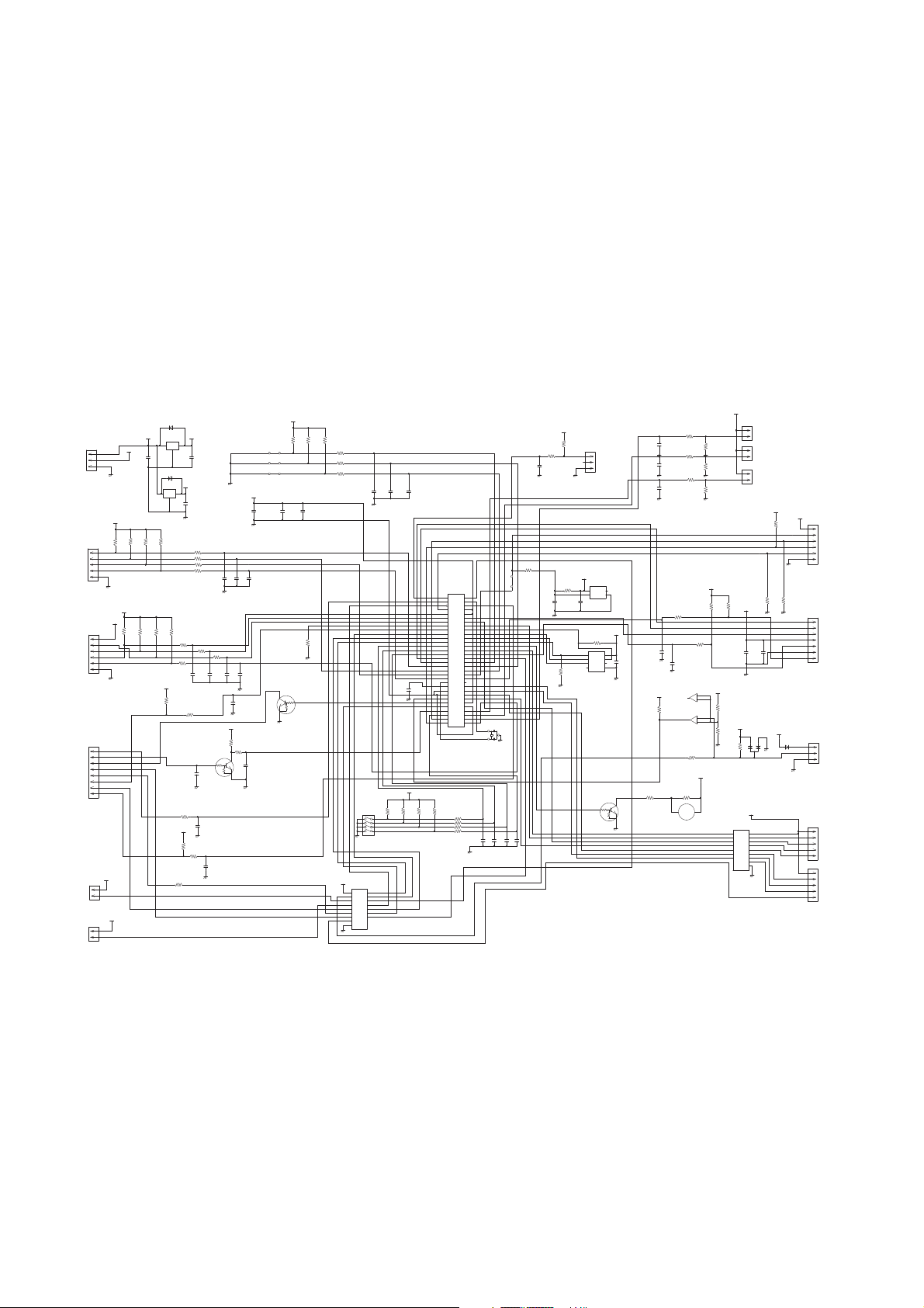
I N D O O R P C B
C I R C U I T D I AG R A M
Page 8
5V
C29
0.1
<F>
R57
1.0k
<1/10W>
R59
10k
<1/10W>
C30
0.1
<F>
R58
1.0k
<1/10W>
R60
49.9k
<1/10W>
C34
0.1
<F>
R62
1.0k
<1/10W>
R61
49.9k
<1/10W>
CN9
B03B-XARK-1-A
( LF ) ( SN )
FLOAT SWITCH
5V
R45
10k
<1/10W>
R46
1.0k
<1/10W>
C31
0.01
<F>
5V
5V
R50
10k
<1/10W>
THERMISTOR ( ROOM TEMP. )
CN8
B02B-XASK-1-A
CN7
B02B-XAYK-1-A
THERMISTOR ( PIPE - M I D. TEMP. )
CN5
B02B-XAKK-1-A
CN15
B06B-XASK-1-A
FLASH
CN13
B07B-PASK-1
I NDICATOR PCB ASSY
CN14
B03B-XAKK-1-A ( LF ) ( SN )
REMOTE CONTROL UNIT
5V
R68, R52
10k <1/10W> x 2
5V
R41
1.0k
<1/10W>
R43, R44
10k <1/10W>
x 2
R42
47
<1/10W>
C24
1000p
<R>
C23
0.01
<F>
C25
10/
50V
+
C26
0.01
<F>
12V
5V
5V
13.5V
13.5V
R47
390
<1/10W>
R35
1.0k
<1/10W>
R36
0R0
I C6-1
BA10393F
I C6-1
BA10393F
R55
10k
<1/10W>
12V
12V
D3
D1FS4A
D2
DAN217U
R54
15.4k
<1/10W>
R53
28k
<1/10W>
R48
10k
<1/10W>
I C4
uLN2003ADR
BZ1
PKM13EPYH-4000-A0
CN11
B05B-XASK-1-A
CN12
B05B-XARK-1-A
LOUVER ( UP / DOWN )
LOUVER ( RIGHT / LEFT )
Q2
DTC124EKA
5V
I C7
S-80842CNNB
R56
100k
<1/10W>
C27
0.1
<F>
C38
0.1
<F>
R69
10k
<1/10W>
R40
10k
<1/10W>
C13
0.1
<F>
R37
10k
<1/10W>
I C5
S-93C66BD0 I
I C1
uPD78F0536AGK
C36
0.47
<F>
JM5
0R0
C8 - C10
0.1 <F> x 3
5V
5V
R4 - R6
1.0k <1/10W> x 3
R1 - R3
10k <1/10W> x 3
JM1
JM2
JM3
C32
100/
6.3V
+
C33
0.1
<F>
C28
0.1
<F>
R19 - R22
1.0k <1/10W> x 4
5V
12V13.5V
5V
C3
0.01
<F>
+
D1
1SS355
I C2
NJM7805
+
C1
10/
50V
C2
10/
50V
I C8
NJM7812
D4
1SS355
5V
R15 - R18
10k <1/10W> x 4
R70
10k
<1/10W>
Q3
DTC124EKA
5V
5V
5V
C19 - C22
0.1 <F> x 4
13.5V
R7 - R10
1.0k <1/10W> x 4
R11 - R14
10k <1/10W> x 4
SW1
CFS-0402MC
I C3
uPA2003ADR
R29
390
<1/10W>
R28
10k
<1/10W>
C16
0.01
<F>
Q1
DTC124EKA
C15
0.01
<F>
C14
1000p
<R>
5V
C17
0.01
<F>
C18
0.01
<B>
R27
330
<1/10W>
R34
1.0k
<1/10W>
R33
10k
<1/10W>
R31
10k
<1/10W>
13.5V
13.5V
R25
1.0k
<1/10W>
R26
10k
<1/10W>
C35, C12, C11
1000p <R> x 3
C37
0.1
<F>
R67
1.0k
<1/10W>
5V
13.5V
R24, R23, R32
10k <1/10W> x 3
R63 - R65
1.0k <1/10W> x 3
R66
10k
<1/10W>
X1
8.00MHz
<FCR>
CN4
B08B-PASK-1
POWER DRIVE
CN3
B06B-PASK-1
TEST
CN2
B5P-SHF-1AA
CN1
B03B-PASK-1
DC SUPPLY
1
2
3
1
2
1
2
1
2
1
2
3
4
5
6
1
2
3
4
5
6
7
1
2
3
1
2
3
4
5
1
2
3
4
5
1
2
3
4
5
6
7
8
1
2
3
4
5
6
1
3
2
3
2
1
8
7
6
5
4
3
2
1
9
16
15
14
13
12
11
10
8
1
2
3
4
5
6
7
SK
O1
O2
O3
O4
O5
O6
O7
GND
I 1
I 2
I 3
I 4
I 5
I 6
I 7
SK
O1
O2
O3
O4
O5
O6
O7
GND
I 1
I 2
I 3
I 4
I 5
I 6
I 7
9
16
15
14
13
12
11
10
8
1
2
3
4
5
6
7
1
3
2
2134VDD
OUTNCGND
1
2
3
4
5
1
2
3
1
2
1
2
123IGO
IGO
1
2
3
CN6
B02B-PAMK-1
FRESH AIR
HEATER
CN10
B02B-PAOK-1
1
2
3
6
8
4
7
5
CS
SK
D I
NC
VCC
DO
NC
GND
NC
34
39
36
43
44
45
46
33
32
31
30
29
28
27
26
18
19
20
21
22
23
11
12
13
14
38
37
41
40
25
9
42
52
51
50
49
48
47
56
55
54
53
8
7
6
5
4
3
2
1
64
63
62
61
60
59
58
57
17
16
15
24
10
35AVREF
I C
RST*
P00
P01
P02
P03
P10
P11
P12
P13
P14
P15
P16
P17
P20
P21
P22
P23
P24
P25
P30
P31
P32
P33
XT1
XT2
X1
X2
AGND
GND0
GND1
P75
P74
P73
P72
P71
P70
P67
P66
P65
P64
P57
P56
P55
P54
P53
P52
P51
P50
P47
P46
P45
P44
P43
P42
P41
P40
P36
P35
P34
VDD1
VDD0
AVDD
3
1
2
3
1 2
3
2
1
7
6
5
+
-
+
-
B. Z.
C4
0.01
<F>
C5
1000p
<R>
C7
1000p
<R>
SP PCB
INDOOR UNIT
CONTROLLER PCB ASSEMBLY ( MAIN PCB )
AUYG12LVLB : K06AK-1104HSE-C1
AUYG14LVLB : K06AK-1105HSE-C1
AUYG18LVLB : K06AK-1106HSE-C1
2011.11.14 7
Page 9
340V
15V
15V
A
6
5
4
3
2
1
CN105
B5P-VH-B
DC FAN MOTOR
I C103
TLP621
<GB>
R114
4.7k
<1/10W>
R115
6.8k
<1/4W>
5V
15V
R116
1.0k
<1/4W>
I C104
TLP621
<GB>
R117
820
<1/4W>
C117
100/
25V
+
A
A
1
2
4
3
4
312
CN104
B08B-PASK-1
1
2
3
4
5
6
7
8
1
2
3
3
2
1
2
1
5V
L102
BLm18
<AG601>
L103
BLm18
<AG601>
I C101
TLP621
<GB>
R112
330
<1/10W>
C116
0.01
<B>
4
3 2
1
13.5V
CN103
B2B-XH-AM
CN102
B3B-XH-AM
5V 13.5V
C121
0.1
<F>
C120
0.1
<F>
CN101
B03B-PASK-1
CN106
B2P3-VH-B-E
5V
I C 1 0 5 H I 2 0 0 3 R 3
VA103
0.01
<KH>
2
1
K102
G5NB-1A
13.5V
RC101
120/
0.1
3 2
4
1
DRAIN PUMP
K101
G5N-1A
4
2
1
3
18 14 10 5
4
3
2 1
5
4 3
2 1
6
7
8
W105
RED
SERIAL
E102
GREEN
C118
0.01
<KH>
D101
D3SB60
4
3
1
2
340V
R104
330k
<2W>
C109
220p
<BN>
R105
75
<RS-2W>
Q101
2SC5354
3
2
1
1
2
3
Q102
2SC1815
R107
100
<1/10W>
R106
1.5
<RS-2W>
15V
D106
D1FL20U
A
C112
330/
25V
+
C111
100/
25V
D104
MTZJ5.1B
D109
MTZJ5.1B
R109
330
<1/4W>
+
R108
100
<1/2W>
D105
D1FL20U
D103
D1FL20U
C110 0.047
<ECQV>
D107
RD16
<B1>
R110
10k
<1/10W>
C114, C115
0.01 <KH>
x 2
13.5VD108
D2FL20U
C113
1000/
25V
T101
ZFT22B03-C
R111
10k
<1/10W>
+
12
10
2
3
5
6
7
8
C108
4700p
<FNS>
R103
62k
<RS-2W>
D102
1SR139-600
C107
100/
450V
+
C105
0.010
<YE>
C106
0.010
<YE>
C104
0.47
<R46>
LF101
ELF17N015A
1 2
4
3
VA102
470V
<TNR>
SA101
RA-362M
VA101
470V
<TNR>
FH101 FH102
F101
3.15A
250V
W101
BLACK
W102
WHITE
E101
GREEN
DC SUPPLY
R113
330
<1/10W>
EXTERNAL I N
EXTERNAL OUT
POWER DRIVE
I C26-14 I C26-10
L N
I C26-14
I C26-10
L
N
I C26-14
I C26-10
L
N
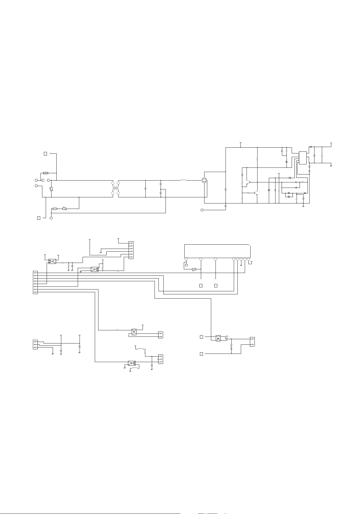
INDOOR UNIT
POWER SUPPLY PCB ASSEMBLY
K06AL-1007HSE-P0
2011.11.14 8
L101
REP28-15
15mH, 1.1A
Page 10

5V
R201 220 <1/4W>
R202 390 <1/4W>
R203 220 <1/4W>
D203 SLR-325MC
GREEN
D201 SLR-325MC GREEN
D202 SLR-325DC ORANGE
PHA201
P I C-37143TH5
SW201
EVQPAG04K
C202
10/
25V
+
C201
0.1
<F>
2
4 3
1
2
1
3
VCC
OUT
GND
CN201
S07B-PASK-2 ( LF ) ( SN )
OPERATE
TIMER
MANUAL AUTO SWITCH
FILTER CLEN / FILTER SIGN
5V
REMOTE CONTROL
GND
1
2
3
4
5
6
7
TO CONTROLLER PCB ASSEMBLY
( MAIN PCB )
INDOOR UNIT
INDICATOR PCB ASSEMBLY ( OPTION )
K06AG-1000HSE-D0
2011.11.14 9
Page 11
REACTOR
W11
B
W10
B
W5 W6
UL1015
AWG14
ORANGE
UL3271
AWG14
RED
UL3271
AWG14
WHITE
W1
B
W2
B
W4
B
W3
B
W7
B
U
W8
B
V
W9
B
W
UL3271
AWG16
RED
UL3271
AWG16
WHITE
UL3271
AWG16
BLACK
RED
WHITE
BLACK
BLACK
BLACK
RED
BLACK
WHITE
YELLOW
BROWN
RED
BROWN
BLUE
ORANGE
YELLOW
WHITE
UL1015
AWG14
BLACK
UL1015
AWG14
WHITE
UL1015
AWG20
RED
UL1015
AWG16
GREEN
BLACK
BLACK
BROWN
BROWN
BLACK
BLACK
BROWN
BROWN
BLACK
BLACK
FRAME FRAME
F202
5A
250V
F201
20A
250V
TERMINAL
W103
UL1015
AWG20
BLACK
W100
UL1015
AWG20
WHITE
W102
UL1015 AWG20
BLACK
W101
UL1015
AWG14
BLACK
N
L
3
2
1
L
N
SERIAL
TO INDOOR UNIT
EARTH
POWER SOURCE
230V
50Hz
1
2
3
4
5
6
7
1
2
3
4
5
6
1
2
3
1
2
3
4
1
2
3
1
2
1
2
CN71
B04B-PASK-1
WHITE
CN70
B03B-PASK-1
WHITE
CN73
B02B-XAMK-1-A
GREEN
CN72
B2B-XH-AM
WHITE
Wire w/TERMINAL ( CORE )
1015#22
GREEN
CN800
B5 ( 7-2.3 ) B-XASK-1-A
WHITE
CN40
B6B-XARK-1-A
RED
CN30
B2P3-VH-B-C
BLACK
THERMISTOR ( PIPE TEMP. )
THERMISTOR ( DISCHARGE TEMP. )
THERMISTOR ( OUTDOOR TEMP. )
THERMISTOR ( COMPRESSOR TEMP. )
THERMISTOR ( PIPE - MID. TEMP. )
F M
DC FAN MOTOR
EXPANSION VALVE
PMV
4-WAY VALVE
C M
COMPRESSOR
EMI FILTER
EMI FILTER
EMI FILTER
EMI FILTER
CONTROLLER PCB ASSEMBLY
AOYG12LALL : K06AX-1104HUE-C1
AOYG14LALL : K06AX-1105HUE-C1
AOYG18LALL : K06AX-1106HUE-C1
INVERTER ASSEMBLY
AOYG12LALL : EZ-0111FHUE
AOYG14LALL : EZ-0111GHUE
AOYG18LALL : EZ-0111HHUE
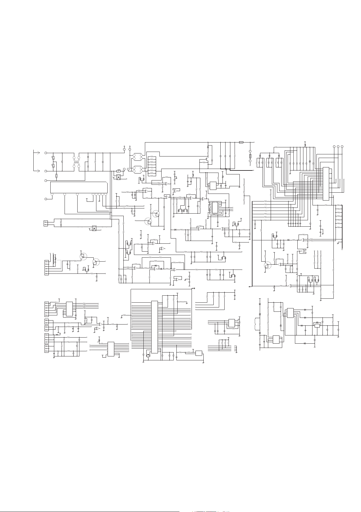
O U T D O O R P C B
C I R C U I T D I AG R A M
2011.11.11 10
Page 12
5V
I C102-4
BA2901F
-
R171
4.7k
+
11
10
13
-
+
6
7
1
-
+
5
6
7
-
+
2
3
1
2
3
1
2
3
1
3
2
1
-
+
5
6
7
-
+
-
+
-
+
5
6
7
2
3
1
-
+
13
12
14
-
+
-
+ 14
9
8
5
4
2
-
+
3
2
1
2
6
4
1
5
7
3
VCC
SO
GND
GAT I N
S I
D I
NC
14
13
12
11
10
9
8
1
2
3
4
5
6
7
3
2 1
-
+
1
2
3
-
+
7
5
6
-
+
3
2
1
-
+
7
6
5
3
2
1
-
+
6
5
7
3
2 1
2
3 4
1
2
3
4
1
324
1
4
1
2
3
3
1
2
3
1
2
3
2 1
421
3
3
2 1
3
2 1
9
10
8
-
+
-
+
6
5
7
3
2
1
-
+
3
2
1
3
2 1
3
3
2 1 2
1
2
1 3
G
I O
8
7
5
1
2
3
4
S
S
D
M
S
S
C
1
2
3
4
5
10
9
8
7
6
1
2
3
4
5
6
7
8
9
10
11
12
13
14
15
16
17
18
19
20
21
22
23
24
25
26
27
P
W
V
U
NW
NV
NU
VCC
COM
I N
I N
I N
VFO
CFOD
CSC
I N
VCC
VB
VS
I N
VCC
VB
VS
I N
VCC
VB
VS
2
7
9
16
4
5
12
13
3
6
11
14
1
8
10
15
O1
O2
O3
O4
GND1
GND2
GND3
GND4
I 1
I 2
I 3
I 4
COM1
COM2
NC1
NC2
16
15
14
13
12
11
10
9
1
2
3
4
5
6
7
8
1B
2B
3B
4B
5B
6B
7B
E
1C
2C
3C
4C
5C
6C
7C
COM
3421VDD
OUT
NC
GND
1
2
3
6
8
4
7
5
VCC
DO
NC
GND
CS
SK
D I
NC
3
1 2
3
1 2
3 3
1
212
17
16
2
35
3
59
58
60
21
34
47
27
28
29
30
31
32
33
57
41
42
43
44
10
9
8
7
5
6
4
22
23
56
11
25
26
40
36
37
38
39
12
45
46
50
51
52
53
54
55
14
15
18
20
64
63
62
61
1
19
48
13
24
49
P63
P62
P46
P12
P50
P37
P36
P40
MD2
P11
P26
P02
P03
P04
P05
P06
P07
P10
C
P20
P21
P22
P23
P57
P56
P55
P54
P52
P53
P51
X0
X1
VCC
AVCC
P00
P01
P17
P13
P14
P15
P16
AVR
P24
P25
P30
P31
P32
P33
P34
P35
P60
P61
MD0
MD1
P44
P43
P42
P41
P45
RSTX
P27
AGND
GND
GND
2
1
3
1
2
3
4
5
6
1
2
3
4
5
6
1
2
1
2
1
2
3
4
1
2
3
1
2 = 3
I C500
MB90460
+
FAN I N/17P
FANPWM/2P
PFCSW/35P
CT/3P
TEST/59P
PFC/58P
TTXD/60P
TAUX3/21P
CTDW/34P
CP-POS/47P
V4-AC/27P
ACFAN/28P
V4-DC/29P
LED/30P
PR/31P
SO/32P
I PM-TR I P/33P
E2CS/41P
EPV2/42P
EPV4/43P
EPV3/44P
TH/10P
I PM-CR/9P
DCV/8P
ACV/7P
TE/5P
TA/6P
TD/4P
E2SK/40P
ZXH/36P
ZXL/37P
E2D I/39P
EPV1/45P
PFC-TR I P/46P
U/50P
X/51P
V/52P
Y/53P
W/54P
Z/55P
PFCEN/14P
TMODE/18P
MD1/64P
MD2/63P
TRXD/61P
MD0/1P
/TRES/19P
S I/48P
E2D I/39P
E2SK/40P
E2CS/41P
TTXD/60P
TRXD/61P
TMODE/18P
/TRES/19P
8 7
6
5
4
3 2
1
18 14
10 5
4 3
2
1
SO/I C80-2
V4-AC/I C80-3
FANPWM/2P
FAN I N/17P
EPV3/44P
EPV4/43P
EPV2/42P
EPV1/45P
CTDW/34P
LED/30P
SO/32P
V4-AC/27P
V4-DC/29P
PR/31P
ACFAN/28P
TH/10P
TE/5P
TD/4P
TA/6P
SO/I C80-2
V4-AC/I C80-3
PR/I C80-5
PFCSW/35P
PFCEN/14P
PFC-TR I P/46P
I PM-CR/9P
I PM-TR I P/33P
DCV/8P
CT/3P
ACV/7P
U/50P
V/52P
W/54P
X/51P
Y/53P
Z/55P
5V
R218
4.7k
<1/10W>
5V
15V
I C570
M93C46
5V
C570
0.1
<F>
R570
10k
5V
R93, R92, R91, R90
10k x 4
MD0/1P
MD1/64P
MD2/63P
TEST/59P
I C560
S80842
5V
R560
100k
R561
1.0k
C561
0.01
<F>
C503
0.1
<F>
C501
10/
25V
C502
0.1
<F>
X500
8.00MHz
<CSTLS>
C500
0.1
<F>
12V
I C80
uLN2003
12V
R80
2.2k
D80
SLR-332
<RED>
I C10-2
BA2903F
R19
1.0k
C13
0.1
<F>
C14
0.1
<F>
5V
15V
R18
10k
I C10-1
BA2903F
12V
I C40
TD62064
12V
C40
0.1
<F>
R40 - R43
1.5k <1/10W> x 4
C12
0.1
<F>
C10, C11
0.1 <F>
x 2
R13
10k
R11
10k
L70
BL02Rn1
5V
R12
13k
1%
R10
4.75k
1%
R71 4.75k
1%
R75
10k
R76
10k
R72
13k
1%
C72
0.1
<F>
R77
10k
C75
0.1
<F>
C73
0.1
<F>
R73
38.3k
1%
C71
0.1
<F>
R14
2.2k
1%
R16
2.2k
1%
R17
2.2k
1%
5V
C801
0.01
<F>
R804
1.0k
D600
DAN217U
5V
R803
10k
<1/10W>
5V
R801
1.0k
<1/4W>
R802
560
<1/4W>
C800
100/
25V
+
15V
Q800
DTC143EUA
Q801
DTA143EUA
C802
0.1
<F>
L800
BL02Rn1
K30
G5NB-1A
12V
JM30
JM31
JM32
CR30
RE1201
0.1 / 120
15V
DCV-F POW_GND
POW_GND
L40
5V
12V
K1
DX12D1
15V
-12V
D105
DAN217U
D101
LL25XB60
R1
ZPR0RCH400
5V
PR/I C80-5
PFC/58P
+
-
W5
ORANGE
W6
ORANGE
W10
WHITE
W11
RED
D100
LL25XB60
REACTOR
+
-
5V
ZXL/37P
S I/48P
PFCEN/14P
Q103
DTC143EUA
Q102
DTC143EUA
R132
2.2k
I C3-1
BA4560
R129
100k
1%
C117
1.0
<B>
I C3-2
BA4560
R130
220
1%
R131
10
<1/10W>
1%
R154
120k
R142
1.2k
1%
+
R400 - R407
0.2 <1W> 1% x 8
15V
5V-2
5V
L130
CAL45VB470K
+
5V
R126
100k
1%
I C103-1
BA4560
R127, R128
10k 1%
x 2
R153 120k
1%
R155
100k
R156
100k
1% x 2
C137
0.1
<F>
C138
2.2/
50V
R157
4.7k
R21
10k
<1/10W>
R20
1.0k
<1/10W>
R22
1.0k
<1/10W>
C21
0.047
<B>
C20
0.1
<F>
R23
27k
<1/10W>
15V
15V
5V
5V
R162
68k
1%
I C105-1
BA2903F
C130
0.1
<F>
R159
4.7k
R160
68k
1%
C129
1000p
<B>
R161
1.5k
1%
R163
10k
1%
I C105-2
BA2903F
ZXH/36P
-12V
R134, R133
10k 1% x 2
I C104-1
BA2902F
15V
-12V
C115
0.1
<F>
C116
0.1
<F>
I C104-4
BA2902F
R168
22k
R169
22k
COMP
5V
R500
10k
R502
1.0k
R503
10k
JM500
5V
5V
D113
DAN217U
C134
0.1
<F>
+
C133
2.2/
50V
C132
2.2/
50V
+
C131
0.1
<F>
R583
1.0k
R581
10k
R582
10k
R584
22k
C580
0.1
<F>
15V
I C50
TOP243PN
C51
1.0
<B>
+
R51
47
C50
47/
35V
L50, L51
BLm21
<A601>
x 2
R50
0R0
D52
1SS355
D51
UDZS8.2B
D50
1SS355
T60
RPZ-1F
D53
UF4005
R57
0R0
C52
2200p
<E>
R56
150k
<2W>
R52
470k
<1/8W>
1%
R53
510k
<1/8W>
1%
R54
510k
<1/8W>
1%
R55
510k
<1/8W>
1%
DCV-F
POW_GND
C66
100/
25V
D62
D1FL20
+
D61
D1FL20U
D60
D1FL20U
D64
1SS355
-12V
C69
100/
25V
+
I C60
BA7805
D63
1SS355
+
C64
330/
25V
12V
5V
+
+
R61
10k
C68
100/
25V
C67
0.1
<F>
C65
470/
25V
15V
R311
8.66k
1%
R309
5.76k
1%
R310
143
1%
C86
470p
<B>
C84
0.1
<F>
C87
330p
<B>
R83
27k
<1/10W>
5V
+
I C302-2
BA2903F
C85
10/
25V
R81
1.0k
<1/10W>
C300
100p
<CH>
15V
D304, D303
DAN217U x 2
R307
195k
<RN-1/2W>
R308
195k
<RN-1/2W>
POW_GND
I PM-G
R305, R303, R301
R306, R304, R302
195k <RN-1/2W>
1% x 6
W
V U
I C300-2
BA4560
-12V
5V 5V
5V
5V
R339
10k
R334
10k
1%
Q300
DTC114EUA
R337
100k
1%
I 302-1
BA2903F
C339
0.01
<F>
C330
1000p
<B>
R335, R336, R333
10k 1% x 3
R331
47k
1%
R329
47k
1%
I C300-1
BA4560
D302
RB751V
R328
1.0k
C311
1000p
<B>
R327
22k
C320
0.15
<ECQV>
D301
DAN217U
5V
4.7k 1%
x 2
R330
R332
I PM-G
C306
0.1
<F>
C305
0.1
<F>
15V
C213
0.022
<F>
C206 - C208, C215 - C217
2200p <B> x 6
R219
1.0k
R220
1.0k
C219
1000p
<B>
I PM-G
C214
2200p
<B>
R210
1.0k
390 <1/10W> x 6
R204
R205
R206
R207
R208
R209
POW_GND
R107
3.83k
1%
D112
DAN217U
+
C109
2.2/
50V
C108
2.2/
50V
+
C107
0.1
<F>
R111
10k
I C102-3
BA2901F
R165
22k
C112
0.1
<F>
C128
0.1
<F>
+
I C102-1
BA2901F
C127
2.2/
50V
C126
2.2/
50V
+
C125
0.1
<F>
R164
22k
C110
0.1
<F>
R117
22k
1%
C111
4700p
<B>
R119
10k
1%
R112
10k
1%
5V-2
R115
22k
1%
R116
15k
1%
5V-2
R118
10k
1%
D107
RB751V
R114
15k
1%
C136
0.01
<F>
R101
4.7k
C141
1000p
<B>
R113
4.7k
1%
C106 0.1
<F>
5V-2
5V
D106
DAN217U
R167
10k
I C101
TC74HC00AF
R110
6.8k
DCV
15V-2
+
R105, R106
195k <RN-1/2W>
1% x 2
C104
10/
25V
C105
0.1
<F>
I C100
TA8316
R124
4.7k
15V
R109
22
<1/4W>
R108
47
<1/4W>
L100
BL02Rn1
DCV-F
POW_GND
DCV
R200
39
<1/2W>
F100
15A
250V
D200 D201 D202
US1J x 3
+
+
+
F4
3.15A
250V
C100 - C102
660uF / 450V x 3
+ + +
R104
220k
<2W>
C103
0.1
<HCP>
D102
UF4007
R103
100
<1/2W>
Q100
GT30J121
R102
47k
I PM-G
U V
W
DCV
I C200
FSBB20CH60
R211
R212
R213
R214
R215
R216
R217
0.15
<1W>
1% x 7
W8W7 W9
U V
W
15V
L300
CAL45VB470K
+
C209 - C211, C212, C221
0.1 <F> x 4
C222 1.0 <F>
D203 ZP1027-TP
C220 47 / 35V
C201 0.1 <F>
C200 47 / 35V
R201 330k
C203 0.1 <F>
C202 47 / 35V
R202 330k
C205 0.1 <F>
C204 47 / 35V
R203 330k
JM101
JM102
JM103
JM100 TEST
COMP
CP-POS/47P
D109
RB751V
I C104-2
BA2902F
D108
RB751V
R141
10k
1%
R135
10k
1%
R137 10k 1%
R136 10k 1%
R138 10k 1%
R140
10k
1%
R143
39k
1%
R139
10k
1%
I C104-3
BA2902F
R146
39k
1%
C124
2200p
<B>
R152
4.7k
1%
C123
2200p
<B>
R149
4.7k
1%
R144
22k
1%
R145
22k
1%
D111
DAN217U
D110
DAN217U
R147, R150
R148, R151
195k <RN-1/2W>
1% x 4
D115, D114
DAN217U x 2
C142
0.1
<F>
C113
2700p
<B>
I C102-2
BA2901F
R121
100k
1%
C140
0.1
<F>
C139
2.2/
50V
R120
4.7k
1%
R125
4.7k
R122
4.7k
1%
R123
4.7k
1%
R166 3.9k
R158 3.9k
I C103-2
BA4560
-12V
C119
0.1
<F>
C120
0.1
<F>
L1
RCH4716-070PF07
C1
1.0
<LE-M>
R2
220k
<2W>
SA1
RA-302M
VA1
470V
<TNR>
VA2
470V
<TNR>
W1
BLACK
L
W2
WHITE
N
W3
GREEN
EARTH
W4
RED
SERIAL
CN30
B2P3-VH-B-C
BLACK
CN801
B5P6-VH-B-L
WHITE
CN40
B06B-XARK-1-A
RED
CN73
B02B-XAMK-1-A
GREEN
CN72
B2B-XH-AM
CN71
B04B-PASK-1
CN70
B03B-PASK-1
THERMISTOR ( OUTDOOR TEMP. )
THERMISTOR ( PIPE TEMP. )
THERMISTOR ( DISCHARGE TEMP. )
THERMISTOR ( COMPRESSOR TEMP. )
THERMISTOR ( PIPE - MID. TEMP. )
ELECTRIC EXPANSION VALVE
DC FAN MOTOR
4-WAY VALVE COIL
I C104
BAYPASS CAPACITOR
I C105
BAYPASS CAPACITOR
I C102
BAYPASS CAPACITOR
I C103
BAYPASS CAPACITOR
I C300
BAYPASS CAPACITOR
POWER SOURCE
AC230V
50Hz
H Y I C 1
G K - 3 0 4 3 4 E 3
C4
0.01
<KH>
C5
0.01
<KH>
C6
3.3
<LE>
FH2
FH1
FC51FL x 2
R340
10k
1%
R338
3.3k
1%
C574, C573
1000p <B>
x 2
C572
1.0k
<1/10W>
R585
1.0k
OUTDOOR UNIT
CONTROLLER PCB ASSEMBLY
AOYG12LALL : K-06AX-1104HUE-C1
AOYG14LALL : K-06AX-1105HUE-C1
AOYG18LALL : K-06AX-1106HUE-C1
2011.10.24 11
Page 13
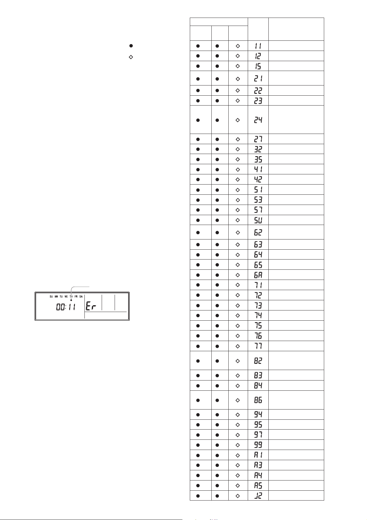
If you use a wireless remote control, the lamp
on the photo detector unit will output error codes
by way of blinking patterns.
If you use a wired type remote control, error
codes will appear on the remote control display.
See the lamp blinking patterns and error codes
in the table. An error display is displayed only
during running.
Indoor unit
Wired
remote
control
INDOOR UNIT
and WIRED REMOTE CONTROL
E R R O R D E T E C T I O N
Description
OPERATION
lamp
(green)
TIMER
lamp
(orange)
ECONOMY
lamp
(green)
(1) (1)
Serial communication error
(1) (2)
Wired remote control
communication error
(1)
(5)
Check run unfinished
(2)
(1)
Unit number or Refrigerant circuit
address setting error
[Simultaneous Multi]
(2) (2)
Indoor unit capacity error
(2) (3)
Combination error
(2)
(4)
Connection unit number •
error (indoor slave unit)
[Simultaneous Multi]
Connection unit number error •
(indoor unit or branch unit)
[Flexible Multi]
(2)
(7)
Master unit, slave unit set-up
error [Simultaneous Multi]
(3)
(2)
Indoor unit PCB model
information error
(3) (5)
Manual auto switch error
(4) (1)
Inlet air temp. sensor error
(4) (2)
Indoor unit Heat Ex. Middle
temp. sensor error
(5)
(1)
Indoor unit fan motor error
(5)
(3)
Drain pump error
(5) (7)
Damper error
(5) (15)
Indoor unit error
(6)
(2)
Outdoor unit main PCB model
information error or
communication error
(6) (3)
Inverter error
(6)
(4)
Active filter error, PFC circuit error
(6) (5)
Trip terminal L error
(6)
(10)
Display PCB microcomputers
communication error
(7)
(1)
Discharge temp. sensor error
(7) (2)
Compressor temp. sensor error
(7) (3)
Outdoor unit Heat Ex. liquid
temp. sensor error
(7) (4)
Outdoor temp. sensor error
(7)
(5)
Suction Gas temp. sensor error
(7) (6)
2-way valve temp. sensor error•
3-way valve temp. sensor error•
(7) (7)
Heat sink temp. sensor error
(8) (2)
Sub-cool Heat Ex. gas inlet •
temp. sensor error
Sub-cool Heat Ex. gas outlet •
temp. sensor error
(8) (3)
Liquid pipe temp. sensor error
(8) (4)
Current sensor error
(8) (6)
Discharge pressure sensor •
error
Suction pressure sensor error•
High pressure switch error•
(9) (4)
Trip detection
(9) (5)
Compressor rotor position
detection error (permanent stop)
(9) (7)
Outdoor unit fan motor error
(9) (9)
4-way valve error
(10) (1)
Discharge temp. error
(10) (3)
Compressor temp. error
(10) (4)
High pressure error
(10) (5)
Low pressure error
(13) (2)
Branch boxes error
[Flexible Multi]
: 0.5s on / 0.5s off
: 0.1s on / 0.1s off
( ) : Number of flashing
This is possible only on a wired remote control.
If an error occurs, the following display will be shown.
(“Er” will appear in the set room temperature display.)
Error code
EX. Self-diagnosis
2011.02.10 12
Page 14

2008.07.25 13
OUTDOOR UNIT
Error contents
Thermistor malfunction
Abnormal discharge temperature
Current surge protection
CT abnormality
Compressor position detection malfunction
PAM voltage abnormality
Timer short
Compressor temperature protection (permanent stop)
PFC surge protection (permanent stop)
Fan malfunction
LED
on 0.1 sec / off 0.1 sec
on
on 0.5 sec / off 0.5 sec
on 2.0 sec / off 2.0 sec
on 0.1 sec / off 2.0 sec
on 5.0 sec / off 0.1 sec
on 1.0 sec / off 1.0 sec
on 2.0 sec / off 5.0 sec
on 5.0 sec / off 2.0 sec
on 5.0 sec / off 5.0 sec
Page 15

1
10
142011.12.12
2
4
7
6
5
8
9
8
11
11
8
8
3
DECORATION PANEL
UTG-UFYD-W
PA R T S
Ref. Description
1 Decoration Panel 9375525040
2 Display Panel
9375529123
3 Receiver Window 9375547011
4 Intake Grille 9375531027
5 Long Life Filter 9375533014
11 Flap Total Assy 9377760029
6 Hook Bracket 9375546014
9375532024
9375530013
7 Grille Hook
8 Panel Cover
9 Indicator PCB Assy
9707371031
10 Connector Cover 9375549015
Part number
Page 16

Flap total assy
Motor holder assy
152011.12.12
(connector : red)
(connector : white)
21
22
23
24
Ref. Description
21 Gear A 9375536015
22 Motor Holder 9375535018
23 Step Motor 9900139070
24 Step Motor 9900139087
Part number
DECORATION PANEL
UTG-UFYD-W
Page 17

162011.12.12
11
9
8
6
4
10
12
3
1
5
2
7
PA R T S
INDOOR UNIT
2 Cabinet A Assy 9375492014
1 Top Plate Assy 9375490027
3 Cabinet B 9375494018
10 Wire Holder 9375478018
9 Bell Mouse 9375503017
11 Drain Pan Sub Assy 9377765024
7 Wire Cover 9375516017
8 Pipe Cover 9375515010
4 Hook R 9375504014
5 Hook L 9375505011
6 Insulation Box Assy 9377764065
12 Drain Cap 9375502010
Ref. Description Part number
Page 18

INDOOR UNIT
25
21
25 2 Stage Turbo Fan Assy 9375480011
24 Turbo Fan Washer 9375487010
22
Evaporator Total Assy (12) 9377914033
22
Evaporator Total Assy (14, 18)
9377914026
23 Evaporator Holder
9375508012
26 Fan Motor 9602436019
21 Separate Wall 9375506018
Ref. Description Part number
27 Fan Motor Holder 9375552015
31 Float Switch 9900361037
32 Drain Port Sub Assy 9375718015
30 Rubber (Pump) 9378426016
28 Pump Assy
9900472030
29 Drain Pump Holder B 9375518011
Ref. Description Part number
172011.12.09
22
23
23
27
26
31
28
32
30
29
24
Page 19

18
2011.12.12
INDOOR UNIT
Control unit
41
42
43
44
47
48
45
46
41 Control Box Cover 9375512019
42 Control Box A 9375511012
4343Controller PCB Assy (12) 9707393927
43 Controller PCB Assy (14) 9707393934
Controller PCB Assy (18) 9707393941
44 Power Supply PCB Assy 9707398250
45 Terminal 9306489045
46 Terminal 9703345012
-- Pipe Thermistor 9703297014
-- Room Thermistor
9900502003
47 Remote Control 9379219006
48 Remote Control Holder 9305642045
Ref. Description Part number
Page 20

2011.12.12 19
2
5
1
6
4
3
OUTDOOR UNIT
P A R T S
2 Top Panel Assy
4 Cabinet Assy
6 Cabinet Right Assy
1 Protective Net
9309230057
9312799404
5 Switch Cover 9315039019
9309236059
7 Valve Cover 9316884007
8 Valve Bracket 9308870070
9315319036
3 Fan Guard Cover 9378110014
Ref. Description Part number
11
9
10
8
7
12
13
13 Propeller Fan
11 Motor Bracket Assy
9 Separator Assy
12 Fan Motor
Reactor Assy10
9309909014
9313432010
9312971015
9601725015
9900641016
14
15
14 Inverter PCB Assy (14)
9707427554
Terminal15
9707427547
14 Inverter PCB Assy (12) 9707427530
14 Inverter PCB Assy (18)
9703874031
Page 21

2011.12.12 20
OUTDOOR UNIT
29
21
23
25
31
32
30
24
37
26
27
28
22
29 4-way Valve Assy
30 3-way Valve Assy
31 Compressor Assy
28 Solenoid
9315311030
9970092015
9313763039
9970033018
Outdoor Thermistor-- 9900210045
Drain Assy-- 9303029015
Ref. Description Part number
32 Compressor Thermistor 9900156046
24 Pulse Motor Valve Assy
25 Condenser Total Assy
21 Base Assy
22 2-way Valve Assy
23 Expansion Valve Coil
Thermistor Assy27
9311641018
9311381068
26
Heat Exchanger Thermistor
9900403010
9308869081
9970093012
9900057039
9900148027
Ref. Description Part number
Page 22

INDOOR UNIT
A C C E S S O R I E S
212011.12.12
DECORATION PANEL
Name and Shape Q’ty Application
Connector cover
1
For covering connector
Tapping Screw
(M5 × 12 mm)
4
For mounting decoration panel
Tapping Screw
(M4 × 12 mm)
1
For mounting connector cover
L angle
2
For mounting the Hook
Wire to the Decoration
panel
Hook wire
2
For suspending the
Decoration panel
Screw [pitch small]
(M4 × 10 mm)
2
For mounting the Hook
Wire (for metals)
Screw [pitch large]
(M4 × 10 mm)
4
For mounting the
L angle and Hook wire
(for resins)
Name and Shape Q’ty Application
Special nut A
(Large flange)
4
For installing indoor unit
Special nut B
(Small flange)
4
For installing indoor unit
Template
(Carton top)
1
For cealing openings cutting
Also used as packing
Drain hose
1
For installing drain pipe
Hose Band
1
For installing drain hose
Drain hose insulation
1
For installing drain pipe
Remote control
1
For air conditioner operation
Battery
2
For remote control
Remote control
holder
1
For installing the remote
control
Tapping screw
(M3 × 12mm)
2
For mounting the remote
control holder
Binder
2
For electrical wiring
Wire clamper
1
For electrical wiring
Coupler heat
insulation
(Small)
1
For indoor side pipe
joint (Liquid pipe)
Coupler heat
insulation
(Large)
1
For indoor side pipe
joint (Gas pipe)
1
1
For drain piping work.
9303029015
Drain pipe
To connect
12,000 BTU model
9370244007
Adapter assy
Q'ty
OUTDOOR UNIT
Name and Shape
Application
Page 23

INVERTER SPLIT TYPE
AIR CONDITIONER (50Hz)
CASSETTE TYPE
Indoor unit Outdoor unit
AUYG24LVLA AOYG24LALA
CONTENTS
SPECIFICATIONS. . . . . . . . . . . . . . . . . . .
DIMENSIONS. . . . . . . . . . . . . . . . . . . . . .
REFRIGERANT SYSTEM DIAGRAM
CIRCUIT DIAGRAM
INDOOR PCB CIRCUIT DIAGRAM
OUTDOOR PCB CIRCUIT DIAGRAM
ERROR DETECTION
PARTS (DECORATION PANEL). . . . . .
PARTS (INDOOR UNIT). . . . . . . . . . . . .
PARTS (OUTDOOR UNIT). . . . . . . . . . .
ACCESSORIES. . . . . . . . . . . . . . . . . . .
. . . . . . . . . . . . . . . . .
. . . . . . . . . . . . . . .
. . .
. . . . .
. . .
10
13
15
18
20
1
2
3
4
5
8
Page 24

SPECIFICATIONS
ELECTRICAL DATA
TYPE Inverter cool & heat
INDOOR UNIT
OUTDOOR UNIT AOYG24LALA
COOLING CAPACITY 6.80 kW
HEATING CAPACITY 8.00 kW
POWER SOURCE 230 V
FREQUENCY
RUNNING CURRENT
INPUT WATTS
E.E.R.
COP
AIR FLOW, INDOOR UNIT 930 m3/h
AIR FLOW, OUTDOOR UNIT 2,470 m3/h
MOISTURE REMOVAL 2.7 L/hr
MAXIMUM CURRENT
Cooling
Heating
Cooling
Heating
Cooling 3.08 kW/kW
Heating
Cooling
Heating
AUYG24LVLA
50 Hz
9.7 A
9.9 A
2.21 kW
2.26 kW
3.54 kW/kW
12.0 A
13.5 A
FAN SPEED
MFF-24RVL
960 r.p.m.
850 r.p.m.
650 r.p.m.
INDOOR UNIT
Discrimination
High
Medium
Low
NOISE LEVEL
INDOOR UNIT
Cooling
INDOOR UNIT
Heating
OUTDOOR UNIT
High
Medium
Low
Quiet
High
Medium
Low
Quiet
Cooling
Heating
49 dB
44 dB
36 dB
30 dB
49 dB
45 dB
40 dB
33 dB
52 dB
53 dB
COMPRESSOR AND REFRIGERANT
TYPE Hermetic type, 4 poles
DISCRIMINATION DA150A1F-20NA
COMPRESSOR WEIGHT (with oil)
PRECHARGED REFRIGERANT
REFRIGERANT TYPE
Pipe length
FULL CHARGE
ADDITIONAL CHARGE
MAXIMUM PIPE HEIGHT 20 m
15 m 1,700 g
20 m
25 m
30 m
10.0 kg
1,700 g
R410A
1,800 g
1,900 g
2,000 g
20 g/m
500 r.p.m.
MFE-24ROAM
1,050 r.p.m.
1,050 r.p.m.
OUTDOOR UNIT
Quiet
Discrimination
Cooling
Heating
DECORATION PANEL
MODEL NAME
DIMENSIONS
WEIGHT
2013.03.25 1
H x W x D
Net / Shipping
UTG-UFYD-W
49 x 700 x 700 mm
2.6 kg / 4.5 kg
DIMENSIONS
INDOOR UNIT
OUTDOOR UNIT 570 x 790 x 315 mm
H x W x D
H x W x D
245 x 570 x 570 mm
WEIGHT
INDOOR UNIT
OUTDOOR UNIT
Net / Shipping 16 kg / 19 kg
Net / Shipping
44 kg / 48 kg
Page 25

DIMENSIONS
Unit : mm
DECORATION
PANEL
700
530(Hanging bolt position
OUTDOOR UNIT
700
790
30
49
578
)
INDOOR
UNIT
245
2013.02.20 2
)
Top view
570
Hanging bolt position
(
540
Side view
10
540
Air flow
320
Drain pipe
mounting place
( 20)
Page 26

REFRIGERANT SYSTEM DIAGRAM
h
T
T
OUTDOOR UNIT INDOOR UNIT
Muffler
4-Way
valve
Muffler
3-Way
valve
Heat exchanger
Compressor
Expansion
valve
: THERMISTOR (COMPRESSOR TEP.)
: THERMISTOR (DISCHARGE TEP.)
: THERMISTOR (HEAT EXCHANGER MED TEP.)
: THERMISTOR (HEAT EXCHANGER OUT TEP.)
: THERMISTOR (OUTDOOR TEP.)
Accumulator
StrainerStrainer
2-Way
valve
Heat exc
: THERMIS
: THERMIS
2011.10.24 3
Page 27

N
M
CIRCUIT DIAGRAM
LOUVER
LOUVER
FAN MOTOR
INDOOR UNIT
M
M
FLOAT SWITCH
1
1
2
2
3
3
FM
4
4
5
5
6
6
7
7
8
8
1
1
2
2
3
3
4
4
5
5
1
1
2
2
3
3
4
4
5
5
BROWN
YELLOW
WHITE
BLACK
RED
RED
ORANGE
YELLOW
PINK
BLUE
RED
ORANGE
YELLOW
PINK
BLUE
BLACK
BLACK
121212 12
CN5 CN7
1
1
2
2
3
3
CN12
4
4
5
5
1
1
2
2
3
3
CN11
4
4
5
5
1
1
CN9
2
2
3
3
1
CN10
2
12
12
GRAY
GRAY
12
12
1
1
2
2
CN105
3
3
POWER SUPPLY
4
4
5
5
PCB
6
6
E101 E102
GREEN
GREEN
GRAY
GRAY
12
CN8
MAIN PCB
CN4 CN1
345678
345678
GRAY
GRAY
GRAY
345678
345678
CN104
12312 12
12
12
GRAY
GRAY
GRAY
12
12
CN101
CN103CN102
BLACK
BLACK
CN3
CN13
CN14
CN6
GRAY
GRAY
W105
W102
W101
CN106
1
2
3
4
5
6
1
2
3
4
5
6
7
1
2
3
1
2
3
3
GRAY
3
3
12
YELLOW
YELLOW
M
THERMISTOR ( PIPE TEMP. )
THERMISTOR ( ROOM TEMP. )
BROWN
1
2
3
4
5
6
7
1
2
3
FRESH AIR
( OPTION )
RED
ORANGE
YELLOW
WHITE
BLUE
PURPLE
RED
WHITE
BLACK
1
1
1
2
2
2
3
3
3
4
4
4
5
5
5
6
6
6
7
7
7
1
WIRED REMOTE CONTROL
RED
WHITE
BLACK
1
TERMINAL
2
3
INDICATOR PCB
( OPTION )
TERMINAL
23
THERMISTOR ( PIPE
THERMISTOR ( DISCHARGE
THER
( COMPRESSOR
THERMISTOR ( PIPE - MID.
THERMISTOR ( OUTDOOR
FUSE 250V 5A
BLACK
TERMINAL
1
(
EX IN ( OPTION )
PUMP
EX OUT ( OPTION )
MOTOR
2013.03.25 4
DRAIN
Page 28

K
INDOOR PCB
CIRCUIT DIAGRAM
CONTROL UNIT
EZ-0122MHSE
CN2-1
CN2-2
CN2-3
CN2-4
CN2-5
CN2
B5P-SHF-1AA
WHITE
POWER SOURCE
AC230V
50Hz
DC FAN MOTOR
F M
L
N
SERIAL
E
EMI FILTER
ZCAT2132-1130
1 T
1
2
3
4
5
6
7
8
UL1015 AWG22 x 5
UL1015
AWG16
GREEN
UL1015
AWG16
GREEN
1
2
3
YELLOW
TERMINAL BOARD
HP-T3031-3-L1
E101
E102
RED
CN105-6
CN105-5
BLACK
CN105-4
WHITE
CN105-3
CN105-2
BROWN
CN105-1
W105
UL1015
AWG20
RED
W102
UL1015
AWG20
WHITE
POWER SUPPLY PCB
K06AL-1201HSE-P0
CN105
B5P6-VH-B
WHITE
UL1015
AWG20
BLACK
W101
AC250V
F101
3.15A
CN104
B08B-PASK-1
WHITE
CN104-1
CN104-2
CN104-3
CN104-4
CN104-5
CN104-6
CN104-7
CN104-8
POWER DRIVE
GRAY
GRAY
GRAY
GRAY
GRAY
GRAY
GRAY
GRAY
UL1430 AWG26 x 8
CN15-1
CN15-2
CN15-3
CN15-4
CN15-5
CN15-6
CN3-1
CN3-2
CN3-3
CN3-4
CN3-5
CN3-6
CN4-1
CN4-2
CN4-3
CN4-4
CN4-5
CN4-6
CN4-7
CN4-8
CN15
B06B-XASK-1-A
WHITE
K06A
CN3
B06B-PASK-1
WHITE
CN4
B08B-PASK-1
WHITE
M
DC SUPPLY
UL1430 AWG26 x 3
EMI FILTER
ZCAT1518-0730
1 T
GRAY
GRAY
GRAY
DRAIN PUMP
M
UL1015 AWG18 YELLOW
UL1015 AWG18 YELLOW
EX. OUT
EX. IN
CN106-1
CN106-2
CN103-1
CN103-2
CN102-1
CN102-2
CN102-3
CN106
B2P3-VH-B-E
BLUE
CN103
B2B-XH-AM
WHITE
CN102
B5P6-VH-B
WHITE
CN101
B03B-PASK-1
WHITE
CN101-1
CN101-2
CN101-3
2013.01.24 5
CN1-1
CN1-2
CN1-3
CN1
B03B-PASK-1
WHITE
Page 29

5
W
4
7
7
7
7
7
7
6
6
6
6
5
5
5
5
5
5
5
5
4
4
4
4
4
4
4
4
3
3
3
D
D
INDOOR UNIT
MAIN PCB
K06AK-1219HSE-C1
DC SUPPLY
POWER DRIVE
FRESH AIR
( OPTION )
HEATER
( OPTION )
CN1
B03B-PASK-1
CN2
B5P-SHF-1AA
CN3
B06B-PASK-1
CN4
B08B-PASK-1
B02B-PAMK-1
CN10
B02B-PAOK-1
CN6
1
2
3
1
2
3
4
5
1
2
3
4
5
6
1
2
3
4
5
6
7
8
13.5V
1
2
1
2
5V
13.5V
13.5V
5V
C1
10/
50V
R15 - R18
10k <1/10W> x 4
R24, R23, R32
5V
10k <1/10W> x 3
<1/10W>
+
I C2
NJM7805
R26
10k
D4
1SS355
I C8
NJM7812
I
1
G
1
IGO
2
5V
R33
10k
<1/10W>
<1/10W>
12V13.5V
3
O
C2
2
10/
50V
D1
1SS355
5V
3
C3
0.01
<F>
R19 - R22
1.0k <1/10W> x 4
R66
10k
<1/10W>
1.0k <1/10W> x 3
R67
1.0k
<1/10W>
R25
1.0k
<1/10W>
R31
10k
<1/10W>
5V
R34
1.0k
R27
<1/10W>
330
+
0.01
<F>
R63 - R65
C35, C12, C11
1000p <R> x 3
<1/10W>
1
C15
0.01
<F>
DTC124EKA
C17
0.01
<F>
C18
0.01
<B>
C4
R28
10k
R1 - R3
5V
10k <1/10W> x 3
JM1
JM2
JM3
R4 - R6
1.0k <1/10W> x 3
5V
100/
6.3V
1000p
<R>
C14
1000p
<R>
C32
C5
C37
<F>
0.1
C33
0.1
<F>
3
2
C28
0.1
<F>
R70
10k
<1/10W>
Q3
DTC124EKA
1
+
C7
1000p
<R>
5V
R29
390
<1/10W>
3
C16
0.01
<F>
2
Q1
C36
0.47
<F>
C8 - C10
0.1 <F> x 3
I C1
uPD78F0
34
AVRE F
39
I C
36
RST*
P00
43
44
P01
45
P02
46
P03
33
P10
32
P11
31
P12
30
P13
29
P14
28
P15
27
P16
26
P17
18
P20
19
P21
20
P22
21
P23
22
P24
23
P25
11
P30
12
P31
13
P32
14
P33
38
XT1
37
XT2
41
X1
40
X2
25
AGND
9
GND0
42
GND1
AVD
VD
VD
P
P
P
P
P
P
P
P
P
P
P
P
P
P
P
P
P
P
P
P
P
P
P
P
P
P
P
P
P
5V
R11 - R1
R7 - R
1.0k <1/10
13.5V
CFS-0402MC
I C3
uPA2003
9
SK
16
O1
O2
15
14
O3
13
O4
12
O5
O6
11
10
O7
8
GND
SW1
8
4
7
3
6
2
5
1
1
I 1
2
I 2
3
I 3
4
I 4
5
I 5
I 6
6
7
I 7
10k <1/10W>
2013.01.24
Page 30

0
D
3
W101
BLACK
W102
WHITE
I C26-10
N
I C26-14
L
F101
3.15A
250V
FH101 FH102
VA101
470V
<TNR>
E101
GREEN
SA101
RA-362M
FC51FL x 2
VA102
470V
<TNR>
LF101
ELF17N015A
12
3
4
C104
0.47
<R46>
C105
0.010
<YE>
C106
0.010
<YE>
L101
REP-28-15
15mH, 1.1A
E102
GREEN
1
D
2
3
4
CN105
B5P6-VH-B
6
5
4
3
2
1
4
32
K101
G5N-1A
4
2
I C101
TLP621
<GB>
BLm18
<AG601>
DC FAN MOTOR
1
3
L102
BLm18
5V
<AG601>
1
L103
13.5V
R112
330
<1/10W>
C116
0.01
<B>
CN103
B2B-XH-AM
1
2
CN102
B3B-XH-AM
3
2
1
EX. OUT
EX. I N
W105
RED
SERIAL
18 14
8
B08B-PASK-1
POWER DRIVE
B03B-PASK-1
DC SUPPLY
CN104
CN101
4.7k
340V
R115
6.8k
<1/4W>
R113
330
<1/10W>
15V
<GB>
1
2
A
15V
R114
<1/10W>
I C104
5V
1
2
3
4
5
6
7
8
TLP621
1
2
<GB>
15V
4
3
R116
1.0k
<1/4W>
R117
<1/4W>
820
I C103
+
C117
100/
25V
A
A
TLP621
4
3
5V 13.5V
1
2
3
C121
0.1
<F>
C120
0.1
<F>
2013.01.24 7
VA103
0.01
<KH>
I C 1
7
I C26-14
L
I C26-14
L
I C26-10
N
Page 31

2
2
2
INDOOR UNIT
INDICATOR PCB
K06AG-1000HSE-D0
TO MAIN PCB
CN201
S07B-PASK-2
R201 220 <1/4W>
R202 390 <1/4W>
1
2
R203 220 <1/4W>
3
4
5
6
7
2
43
1
D201 SLR-3
D202 SLR-3
D203 SLR-3
C202
+
10/
25V
C201
0.1
<F>
SW201
EVQPAG04K
2013.01.24 8
P I
Page 32

R
N
2
OUTDOOR PCB
CIRCUIT DIAGRAM
INVERTER ASSEMBL Y
EZ-0121EHUE
TO INDOOR UNIT
POWER SOURCE
AC230V
50Hz
SERIAL
L
N
TERMINAL
1
2
3
4
5
W103
UL1015
AWG20
BLACK
W100
UL1015
AWG20
WHITE
W102
UL1015 AWG20 BLACK
W101
UL1015 AWG14
BLACK
EMI FILTER
ATFC-25-15-12
2 T
F202
5A 250V
F201
20A 250V
EMI FILTER
ATFC-25-15-12
EARTH
1 T
UL1015
AWG14
BLACK
UL1015
AWG14
WHITE
UL1015
AWG20
RED
UL1015
AWG16
GREEN
W1
W2
W4
W3
B
B
B
B
UL3271
AWG14
WHITE
W11
W10
B
B
THERMISTOR ( PIPE TEMP. )
THERMISTOR ( DISCHARGE TEMP. )
THERMISTOR ( OUTDOOR TEMP. )
THERMISTOR ( COMPRESSOR TEMP. )
THERMISTOR ( PIPE - M I D. TEMP. )
BLACK
BLACK
BROWN
BROWN
BLACK
BLACK
BROWN
BROWN
BLACK
BLACK
1
2
CN71
B04B-PASK-1
3
WHITE
4
1
CN70
2
B03B-PASK-1
WHITE
3
1
CN73
B02B-XAMK-1-A
2
GREEN
1
CN72
B2B-XH-AM
2
WHITE
MAI
K06AX-1
2013.01.22 9
Page 33

A
E
Z
E
E
R
/
T
1
k
F
3
M
R
1
1
0
%
5
2
2
k
3
k
C
A
C
POWER SOURCE
AC230V
50Hz
EARTH
SERIAL
CN30
B2P3-VH-B-C
4-WAY VALVE COIL
DC FAN MOTOR
ELECTRIC EXPANSION VALVE
B02B-XAMK-1-A
THERMISTOR ( COMPRESSOR TEMP. )
THERMISTOR ( PIPE - MID. TEMP. )
THERMISTOR ( PIPE TEMP. )
THERMISTOR ( DISCHARGE TEMP. )
THERMISTOR ( OUTDOOR TEMP. )
BLACK
CN801
B5P6-VH-B-L
WHITE
CN40
B06B-XARK-1-A
CN73
GREEN
CN72
B2B-XH-AM
CN71
B04B-PASK-1
CN70
B03B-PASK-1
L
N
RED
W1
BLACK
VA1
470V
<TNR>
VA2
470V
<TNR>
W2
WHITE
SA1
RA-302M
W3
GREEN
18 14
W4
87
RED
1
2 = 3
DCV-F POW_GND
15V
L800
BL02Rn1
1
C802
2
0.1
3
<F>
4
5
6
L40
1
2
3
4
C41
5
6
1
2
1
2
1
2
3
4
1
2
3
C75
0.1
<F>
0.1
<F>
R10
4.75k
1%
R71 4.75k
1%
R72
13k
1%
R73
38.3k
1%
OUTDOOR UNIT
MAIN PCB
K06AX-1200HUE-C1
2
1
C1
1.0
<LE>
4
3
L1
RCH4716-070PF07
H Y I C 1
H U 2 0 0 1 R 3
10 5
6
5V
JM32
CR30
RE1201
0.1/120
12V
R12
13k
1%
5V
L70
BL02Rn1
2
7
9
16
4
5
12
13
C800
100/
25V
+
POW_GND
I C40
TD62064
O1
O2
O3
O4
GND1
COM1
GND2
COM2
GND3
GND4
R13
10k
R11
10k
R75
10k
R76
10k
R77
10k
R801
1.0k
<1/4W>
R802
560
<1/4W>
3
I 1
6
I 2
11
I 3
14
I 4
1
8
10
NC1
15
NC2
C72
0.1
<F>
C73
0.1
<F>
JM31
15V
1
3
5V
R803
10k
<1/10W>
12V
R40 - R43
1.5k <1/10W> x 4
R14
2.2k
C40
1%
0.1
<F>
R16
2.2k
1%
C10, C11
0.1 <F>
C71
0.1
TE/5P
<F>
TD/4P
TA/6P
12V
2
Q801
DTA143EUA
5V
21
DAN217U
3
5V
R15
2.87k
R17
2.2k
1%
TH/10P
x 2
SLR-332VR
R804
EPV3/44P
EPV4/43P
EPV2/42P
EPV1/45P
C4
0.01
<KH>
C5
0.01
<KH>
5
K32
G5N-1A
421
3
1
D600
1.0k
C12
0.1
<F>
6
D80
<RED>
SO/I C80-2
V4-AC/I C80-3
PR/I C80-5
43
3
4
SO/I C80-2
3
2
Q800
DTC143EUA
FAN I N/17P
C801
0.01
<F>
I C10-1
BA2903F
3
+
2
-
-
7
+
5
I C10-2
BA2903F
12V
R80
2.2k
12V
C6
3.3
<LE>
1
2
2
1
JM30
V4-AC/I C80-3
FANPWM/2P
5V
15V
1
C13
0.1
<F>
uLN2003
16
15
14
13
12
11
10
9
ZPR0RCH400
12V
DX12D1-O(M)
R23
27k
<1/10W>
R18
10k
R19
1.0k
I C80
1C
1B
2B
2C
3B
3C
4B
4C
5B
5C
6B
6C
7B
7C
E
COM
R1
324
5V
R149
4.7k
1%
1
2
3
4
5
6
7
8
W10
WHITE
ORANGE
1
K1
PFC/58P
R21
39k
<1/10W>
R22
1.0k
<1/10W>
D111
DAN217U
C123
2200p
<B>
R152
4.7k
1%
CTDW/34P
C14
0.1
<F>
LED/30P
SO/32P
V4-AC/27P
V4-DC/29P
PR/31P
ACFAN/28P
REACTOR
W11
RED
LL25XB60
2
34
W6
ORANGE
DAN217U
C138
2.2/
50V
R157
4.7k
R20
1.0k
<1/10W>
C21
0.1
<B>
R147, R150
R148, R151
1% x 4
15V
D110
21
3
21
3
LL25XB60
2
3
D105
C137
0.1
<F>
+
PFCEN/14P
W5
PR/I C80-5
195k <RN-1/2W>
DAN217U
-12V
R144
22k
1%
9
10
R145
22k
1%
R146
39k
C124
2200p
<B>
CP-POS/47P
I PM-TR I P/33P
I PM-CR/9P
D100
+
-
D101
+
-
-12V
R155
100k
R156
100k
1% x 2
ZXL/37P
S I/48P
C20
0.022
<F>
Q103
DTC143EUA
15V
C130
0.1
<F>
R159
4.7k
C129
1000p
<B>
R143
39k
1%
-
8
+
I C104-3
BA2902F
1%
FAN I N/17P
FANPWM/2P
PFCSW/35P
CT/3P
TEST/59P
PFC/58P
TTXD/60P
TAUX3/ 21P
CTDW/34P
V4-AC/27P
ACFAN/28P
V4-DC/29P
LED/30P
PR/31P
SO/32P
E2CS/41P
EPV2/42P
EPV4/43P
EPV3/44P
TH/10P
DCV/8P
ACV/7P
TE/5P
TA/6P
TD/4P
C500
0.1
<F>
R400 - R407
0.2 <1W> 1%
1
1
4
15V
21
3
R153 120k
1%
-
6
+
5
I C3-2
BA4560
R154
120k
R132
2.2k
Q102
DTC143EUA
2
I C105
BAYPASS CAPACITOR
5V
R160
68k
1%
R161
1.5k
1%
R137 10k 1%
R140
10k
1%
R139
10k
1%
1
x 8
R127, R128
10k 1%
7
R142
1.2k
1%
R131
10
5V
2
3
1
R162
68k
1%
3
+
2
-
I C105-1
BA2903F
R138 10k 1%
D109
RB751V
-
6
+
5
I C104-2
BA2902F
I C500
MB90F462
VCC
P63
17
AVCC
P62
16
P46
2
P12
35
P50
3
59
P37
P36
58
P40
60
MD2
21
AVR
34
P11
47
P26
P02
27
P03
28
29
P04
P05
30
P06
31
P07
32
P10
33
57
C
P20
41
MD0
P21
42
P22
43
MD1
P23
44
P57
10
P56
9
P55
8
7
P54
RSTX
P52
5
P53
6
P51
4
AGND
GND
X0
22
GND
X1
23
3
X500
8.00MHz
2
<CSTLS>
x 2
R130
220
1%
3
1
5V
R163
10k
1%
1
6
5
I C105-2
BA2903F
R136 10k 1%
7
D108
RB751V
56
11
P00
25
P01
26
40
P17
P13
36
37
P14
P15
38
P16
39
12
P24
45
46
P25
50
P30
P31
51
P32
52
53
P33
54
P34
P35
55
P60
14
P61
15
18
20
P44
64
P43
63
P42
62
P41
61
P45
1
19
P27
48
13
24
49
R126
100k
I C103-1
BA4560
2
3
R129
100k
1%
2
3
I C3-1
BA4560
C117
<B>
ZXH/36P
-
7
+
R135
R500
10k
C502
0.1
<F>
1%
-
+
-
+
1.0
10k
1%
R141
10k
1%
1
1
R502
1.0k
C501
10/
25V
15V
C119
0.1
<F>
-12V
R166 3.9k
RB751V
R134, R133
10k 1% x 2
I C104-1
BA2902F
2
3
+
C503
0.1
<F>
C120
-
6
+
5
R158 3.9k
D107
-
+
13
12
I C104-4
BA2902
I C103
BAYPASS
0.1
<F>
7
R12
4.7
1%
R12
4.7
1%
1
D11
DAN
1
-
+
5V
R50
10k
PFC-T
PFCEN
R56
1.0
C561
0.01
<F>
I
B
3
R1
1
1
14
J
T
2013.01.23
Page 34

ERROR DETECTION
u
R
)
)
)
)
)
)
)
)
)
)
)
)
)
)
)
)
)
)
)
)
)
)
0
WIRED REMOTE CONTROL
This is possible only on a wired remote control.
.
OPERATION
If an error occurs, the following display will be shown.
(“Er” will appear in the set room temperature display.)
indoor unit
EX. Self-diagnosis
Error codeUnit number of
INDOOR UNIT (CASSETTE)
ECONOMY Lamp
(GREEN)
TIMER Lamp
(ORANGE)
OPERATION Lamp
(GREEN)
MANUAL AUTO
: 0.5s on / 0.5s off
: 0.1s on / 0.1s off
( ) : Number of flashing
Indoor unit
lamp
(green)
(1) (1)
(1) (2)
(1)
(2)
(2) (2)
(2) (3)
(2)
(2)
(3)
(3)
(3) (5)
(4) (1)
(4) (2)
(5)
(5)
(5) (7)
(5) (15)
(6)
(6) (3)
(6)
(6) (5)
(6)
TIMER
lamp
(orange)
(5)
(1)
(4)
(7)
(1)
(2)
(1)
(3)
(2)
(4)
(10)
ECONOMY
lamp
(green)
Wired
remote
control
Description
Serial communication error
Wired remote control communication error
Check run unfinished
Unit number or Refrigerant circuit address setting error
[Simultaneous Multi]
Indoor unit capacity error
Combination error
Connection unit number error (indoor slave unit)•
[Simultaneous Multi]
Connection unit number error (indoor unit or branch unit)
•
[Flexible Multi]
Master unit, slave unit set-up error
[Simultaneous Multi]
Power supply interruption error
Indoor unit PCB model
information error
Manual auto switch error
Inlet air temp. sensor error
Indoor unit Heat Ex. Middle temp. sensor error
Indoor unit fan motor error
Drain pump error
Damper error
Indoor unit error
Outdoor unit main PCB model information error
or communication error
Inverter error
Active filter error, PFC circuit error
Trip terminal Lerror
Display PCB microcomputers communication error
OPERATION
lamp
(green)
(7)
(7) (2
(7) (3
(7) (4
(7)
(7) (6
(7) (7
(8) (2
(8) (3
(8) (4
(8) (6
(9) (4
(9) (5
(9) (7
(9) (8
(9) (9
(9) (1
(10) (1
(10) (3
(10) (4
(10) (5
(13) (2
Indoor
TIME
lamp
(orange
(1
(5
2013.03.25
11
Page 35

8
PARTS
DECORATION PANEL
UTG-UFYD-W
11
8
11
1
5
10
8
8
9
3
2
4
7
6
Ref. Description
1 Decoration Panel 9375525040
2 Display Panel 9375529123
3 Receiver Window 9375547011
4 Intake Grille 9375531027
5 Long Life Filter 9375533014
6 Hook Bracket 9375546014
Part number
7 Grille Hook
8 Panel Cover
9 Indicator PCB Assy 9707371031
10 Connector Cover 9375549015
1 1 Flap Total Assy 9377760029
132011.12.12
9375532024
9375530013
Page 36

DECORATION PANEL
UTG-UFYD-W
Flap total assy
Motor holder assy
21
(connector : white)
(connector : red)
Ref. Description
21 Gear A 9375536015
23
22
24
Part number
22 Motor Holder 9375535018
23 Step Motor 9900139070
24 Step Motor 9900139087
142011.12.12
Page 37

PARTS
INDOOR UNIT
3
1
6
8
4
2
5
7
9
Ref. Description Part number
1 Top Plate Assy 9375490027
2 Cabinet A Assy 9375492014
3 Cabinet B 9375494018
4 Hook R 9375504014
5 Hook L 9375505011
6 Insulation Box Assy 9377764058
10
7 Wire Cover 9375516017
8 Pipe Cover 9375515010
11
9 Bell Mouse 9375503017
10 Wire Holder 9375478018
11 Drain Pan Sub Assy 9377765017
152012.04.24
Page 38

INDOOR UNIT
23
27
22
21
23
26
25
24
30
29
28
32
Ref. Description Part number
21 Separate Wall
31
9375506018
Ref. Description Part number
27 Fan Motor Holder
9375552015
2012.09.20
22 Evaporator T otal Assy
23 Evaporator Holder
24 Turbo Fan Washer 9375487010
25 2 Stage Turbo Fan Assy
26 Fan Motor
9375720018
9375507015
9375480011
9602436019
28 Pump Assy
29 Drain Pump Holder B
30 Rubber (Pump) 9378426016
31 Float Switch
32 Drain Port Sub Assy
16
9900472030
9375518011
9900361037
9375718015
Page 39

INDOOR UNIT
41
44
46
42
43
45
Ref. Description Part number
41 Control Box Cover 9375512019
47
2012.04.24
48
17
42 Control Box A 9375511012
43 Main PCB 9709245149
44 Power Supply PCB 9707398380
45 Terminal 9306489045
46 Terminal 9703345012
47 Remote Control 9379219006
Remote Control Holder
48
-- Pipe Thermistor 9703297014
-- Room Thermistor 9900502003
9305642045
Page 40

PARTS
OUTDOOR UNIT
3
2
10
9
8
1
7
6
11
4
5
182013.05.27
Page 41

OUTDOOR UNIT
22
33
25
21
26
23
24
27
35
34
2013.05.29
30
28
29
19
Page 42

ACCESSORIES
INDOOR UNIT
DECORATION PANEL
UTG-UFYD-W
Name and Shape Q’ty Use
Coupler heat
insulation
For indoor side pipe
joint (Gas pipe)
1
(Large)
Coupler heat
insulation
For indoor side pipe
joint (Liquid pipe)
1
(Small)
Special nut A
(Large flange)
For installing indoor unit
4
Special nut B
(Small flange)
Template
(Carton top)
For installing indoor unit
4
For cealing openings cutting
Also used as packing
1
Drain hose
For installing drain pipe
1
Name and Shape Q’ty Use
Connector cover
For covering connector
1
Tapping Screw
(M5 × 12 mm)
Tapping Screw
(M4 × 12 mm)
L angle
Hook wire
Screw [pitch small]
(M4 × 10 mm)
For mounting decoration panel
4
For mounting connec-
1
tor cover
For mounting the Hook
Wire to the Decoration
2
panel
For suspending the
2
Decoration panel
For mounting the Hook
Wire (for metals)
2
Hose Band
Drain hose insulation
Remote control
Battery
Remote control
holder
Tapping screw
(M3 × 12mm)
For installing drain hose
1
For installing drain pipe
1
For air conditioner operation
1
For remote control
2
For installing the remote
1
control
For mounting the remote
2
control holder
Screw [pitch large]
(M4 × 10 mm)
OUTDOOR UNIT
Name and Shape
Drain pipe
Q'ty
For outdoor unit
drain piping work.
1
For mounting the
L angle and Hook wire
4
(for resins)
Part numberApplication
9303029015
Binder
Wire clamper
For electrical wiring
2
For electrical wiring
1
202013.02.21
Page 43

INDOOR UNIT
OPTIONAL PARTS
Name and Shape Model name Use
Wired remote
control
UTY-RNNYM
Simple remote
control
UTY-RSNYM
Air outlet shutter plate
UTR-YDZB
Unit control is performed by
wired remote control
Unit control is performed by
simple remote control
Air outlet shutter plate is installed
at the air outlet when 3-way
direction is performed.
Insulation kit
for high humidity
Fresh air
intake kit
Extrenal connect set
Insulation
Kit
UTZ-KXGC
UTZ-VXAA
UTY-XWZX
Install when the under roof
condition is expected to be
the humidity of over80 % and
the temperature of over 30
It can be taken in fresh air of up
to 10% of "high" air volume of the
indoor unit by attaching Fresh Air
lntake Kit to cassette type
indoor unit.
Use to connect with various
peripheral devices and air
conditioner PCB.
2012.04.25 21
 Loading...