

Page 1

SPLIT TYPE
AIR CONDITIONER
DUCT TYPE (50Hz)
Indoor unit Outdoor unit
ARYG12LHTBP
ARYG14LHTBP
AOYG12LBLA
AOYG14LBLA
CONTENTS
SPECIFICATIONS . . . . . . . . . . . . . . . . . .
1
DIMENSIONS. . . . . . . . . . . . . . . . . . . . . .
2
REFRIGERANT SYSTEM DIAGRAM . . .
4
ERROR DETECTION . . . . . . . . . . . . . . . .
6
CIRCUIT DIAGRAM. . . . . . . . . . . . . . . . .
5
PCB CIRCUIT DIAGRAM . . . . . . . . . . . .
8
PARTS (INDOOR UNIT). . . . . . . . . . . . . .
9
PARTS (OUTDOOR UNIT) . . . . . . . . . . .
13
ACCESSORIES . . . . . . . . . . . . . . . . . . .
16
Page 2

12016.02.18
SPECIFICATIONS
TYPE
INDOOR UNIT
OUTDOOR UNIT
POWER SOURCE
Operating current
Operating current
Max operating current
Max operating current
Cooling
Capacity
Capacity
Power consumption
Power consumption
Heating
EER
COP
Dehumidification
AIR CIRCULATION
ELECTRICAL DATA FAN REVOLUTION
DIMENSIONS
INDOOR UNIT
High
Medium
Low
Quiet
950 rpm
780 rpm
690 rpm
610 rpm
OUTDOOR UNIT (heat)
INDOOR UNIT
300 x 700 x 700 mm
OUTDOOR UNIT H x W x D
H x W x D
WEIGHT
INDOOR UNIT
27 kg / 34 kg
OUTDOOR UNIT Net / Shipping
Net / Shipping
0.7 L/h
ARYG12LHTBP
AOYG12LBLA
4.2 A
4.7 A
0.90 kW
3.50 kW
1.00 kW
3.89 kW/kW
4.10 kW/kW
Single phase 230 V 50 Hz
850 m
3
/h
MFG-ZA3VA3N
MFE-63NOM
700 rpm
578 x 790 x 300 mm
40 kg / 44 kg
COMPRESSOR AND REFRIGERANT
NOISE LEVEL
10.5 A
OUTDOOR UNIT (heat) 48 dB
Pipe length
15 m 1,150 g
FULL CHARGE
COMPRESSOR TYPE
DISCRIMINATION
WEIGHT (with oil)
REFRIGERANT TYPE
20 m 1,250 g
ADDITIONAL CHARGE
MAXIMUM PIPING HEIGHT
PRECHARGED
DA130A1F-25NA
25 m 1,350 g
20 g/m
15 m
1,000 rpm
820 rpm
740 rpm
640 rpm
0.9 L/h
Inverter cooling & heating
ARYG14LHTBP
AOYG14LBLA
5.4 A
5.7 A
1.18 kW
4.30 kW
1.25 kW
4.10 kW 5.00 kW
3.64 kW/kW
4.00 kW/kW
950 m
3
/h
680 m3/h 760 m3/h
590 m3/h
670 m3/h
510 m3/h
570 m3/h
1,780 m3/h
1,910 m3/h
1,630 m3/h
1,740 m3/h
750 rpm
OUTDOOR UNIT (cool)
770 rpm 820 rpm
INDOOR UNIT
High
Medium
Low
Quiet
OUTDOOR UNIT (heat)
OUTDOOR UNIT (cool)
High
32 dB
INDOOR UNIT
Medium
27 dB
Low
26 dB
Quiet
24 dB
33 dB
28 dB
27 dB
25 dB
49 dB
OUTDOOR UNIT (cool) 47 dB 49 dB
1,250 g
1,150 g 1,250 g
1,350 g
1,450 g
13.0 A
8.0 A 9.5 A
INDOOR UNIT
OUTDOOR UNIT
FAN MOTOR DISCRIMINATION
9.6 kg
R410A
Hermetic type, 4 poles,
DC motor, Twin Rotary
Page 3

INDOOR UNIT
ARYG12LHTBP
ARYG14LHTBP
unit : mm
740
255
300
650
700
700
22
631
184462
217
25
DIMENSIONS
2016.02.29 2
Page 4

OUTDOOR UNIT
AOYG12LBLA
AOYG14LBLA
unit : mm
347
540
300
66790
578
320
10
2016.02.18 3
Page 5

REFRIGERANT SYSTEM DIAGRAM
OUTDOOR UNIT INDOOR UNIT
2016.02.18
StrainerStrainer
4-way
valve
2-way
valve
3-way
valve
Muffler
Muffler
Expansion
valve
Compressor
Accumulator
Heat
exchanger
Heat
exchanger
Cooling
<Refrigerant flow>
Heating
: Compressor thermistor
: Pipe thermistor
: Room thermistor
: Discharge pipe thermistor
: Heat exchanger thermistor (Middle)
: Heat exchanger thermistor (Out)
: Outdoor thermistor
<Refrigerant pipe diameter>
12
Liquid : 1/4" (6.35 mm)
Gas : 3/8" (9.52 mm)
14
Liquid : 1/4" (6.35 mm)
Gas : 1/2" (12.70 mm)
4
Page 6

Compressor
CM
FM
Fan motor
R(R)
S(S)
C(T)
Reactor
Expansion valve coil
4-Way valve coil
4WV
PMV
W10
W11
CN71
CN73
CN72
CN70
W4
W2
W1
W3
W7
W8
W9
CN800
CN40
CN30
1
2
3
4
5
6
7
1
2
3
4
5
6
7
1
2
3
4
5
1
2
3
4
5
1
2
3
1
2
3
1
2
3
4
1
2
3
4
121
2
1
2
1
2
1
2
3
1
2
3
Fuse
250V
20A
Fuse
250V
5A
1 2
(N)
3 L N
Power source
Terminal
Thermistor ( Pipe temp. )
Thermistor ( Discharge temp. )
Thermistor ( Compressor temp. )
Thermistor ( Pipe - mid. temp. )
Thermistor ( Outdoor temp. )
Black
Black
White
Red
Black
Black
Brown
Brown
Brown
Brown
Black
Black
Red
White
Black
Black
Black
Black
Green
Red
White
Black
Black
Red
White
Yellow
Blue
Red
Blue
Orange
Yellow
White
Black
Black
Main PCB
White
Black
12
Black
Black
Black
Gray
Red
Orange
Orange
Yellow
Blue
Black
White
Red
Black
Black
Red
White
Black
White
Red
Green
Yellow
Blue
Gray
Violet
Brown
White
White
White
White
White
White
White
White
White
White
White
White
White
White
White
White
White
White
White
White
Green
Green
Red
White
Black
11
10
9
8
7
6
5
4
3
2
1
121
2
12
11
10
9
8
7
6
5
4
3
2
1
12
11
10
9
8
7
6
5
4
3
2
1
10
9
8
7
6
5
4
3
2
1
10
9
8
7
6
5
4
3
2
1
10
9
8
7
6
5
4
3
2
1
10
9
8
7
6
5
4
3
2
1
9
8
7
6
5
4
3
2
1
9
8
7
6
5
4
3
2
1
9
8
7
6
5
4
3
2
1
9
8
7
6
5
4
3
2
1
4
3
2
1
4
3
2
1
3
2
1
3
2
1
4
3
2
1
4
3
2
1
1
2
3
1
2
3
1
2
3
1
2
3
3
2
1
3
2
1
4
3
2
1
4
3
2
1
4
3
2
1
4
3
2
1
4
3
2
1
4
3
2
1
5
4
3
2
1
5
4
3
2
1
2
1
5
4
3
2
1
1 2 3 4 5 6 7 8 9 1011
1 2 3 4 5 6 7 8 9 1011
4 3 2 1
4 3 2 1
1 2 3 4 5
1 2 3 4 5
CN302
CN410
CN72
CN2
TMA1 TMB1
CN8
CN9
CN1
CN47
CN66
CN55
CN54
W100
CN73
CN8
CN32
CN65
CN46
CN14
CN9
CN71
CN48
CN303
CN304
CN470
E300
CN370
W300
W302
W301
F300
FUSE
10A 250V
CN1
Y1 Y2 Y3 1 2 Y1 Y2 Y3
3 2 1Terminal
Reactor
M Drain pump
Float switch
Terminal
1 2 C 1 2 345 6
( 3-Wire type )
( To Ex. in )
( To Ex. out )
To Remote
control
( 2-Wire type )
Ex. in
Indicator PCB
( Option )
Main PCB
Power supply PCB
Ex. out
( Option )
( Test )
( Test )
Thermistor
( Room temp. )
Thermistor
( Pipe temp. )
7
6
5
4
3
2
1
7
6
5
4
3
2
1
White
Yellow
Brown
Black
Red
Fan motor FM
( Test )
External in out PCB
( Option )
Communication PCB
( Non polar 2-wire )
INDOOR UNIT
OUTDOOR UNIT
2016.02.29 5
CIRCUIT DIAGRAM
Page 7

CN8-1
CN8-2
CN8-3
CN8-4
CN65-1
CN65-2
CN65-3
CN65-4
CN48-1
CN48-2
CN48-3
CN48-4
CN48-5
CN48-6
CN48-7
CN48-8
CN48-9
CN1-1
CN1-2
CN1-3
CN1-4
CN1-5
CN1-6
CN1-7
CN1-8
CN1-9
CN11-1
CN11-2
CN11-3
CN11-4
CN11-5
CN9-1
CN9-2
CN9-3
CN71-1
CN71-2
CN71-3
CN71-4
CN32-1
CN32-2
CN32-3
CN8-1
CN8-2
CN14-1
CN14-2
CN14-3
CN46-1
CN46-2
CN46-3
CN72-1
CN72-2
CN72-3
CN72-4
CN72-5
CN72-6
CN72-7
CN72-8
CN72-9
CN72-10
CN72-11
CN2-1
CN2-2
CN2-3
CN2-4
CN2-5
CN2-6
CN2-7
CN2-8
CN2-9
CN2-10
CN2-11
CN47-1
CN47-2
CN66-1
CN66-2
CN66-3
CN66-4
CN66-5
CN410-1
CN410-2
CN410-3
CN410-4
CN410-5
CN73-1
CN73-2
CN73-3
CN73-4
CN73-5
CN73-6
CN73-7
CN73-8
CN73-9
CN73-10
CN73-11
CN73-12
CN470-1
CN470-2
CN470-3
CN470-4
CN470-5
CN470-6
CN470-7
CN470-8
CN470-9
CN470-10
CN470-11
CN470-12
CN55-1
CN55-2
CN55-3
CN55-4
CN55-5
CN55-6
CN55-7
CN55-8
CN55-9
CN55-10
CN304-1
CN304-2
CN304-3
CN304-4
CN304-5
CN304-6
CN304-7
CN304-8
CN304-9
CN304-10
CN54-1
CN54-2
CN54-3
CN54-4
CN303-1
CN303-2
CN303-3
CN303-4
CN1-1
CN1-2
CN1-3
CN1-4
CN1-5
CN370-1
CN370-4
CN370-5
CN370-6
CN370-7
CN302-1
CN302-4
1-1
1-2
1-3
1-4
1-5
1-6
SIGNAL1
SIGNAL2
COM
CN9-2
CN9-1
CN9-3
CN9-4
CN9-5
CN9-6
CN9-7
CN9-8
CN9-9
CN9-10
CN9-11
CN9-12
BLACK
WHITE
RED
GREEN
YELLOW
BLUE
GRAY
VIOLET
BROWN
BLACK
WHITE
RED
GREEN
YELLOW
BLUE
GRAY
VIOLET
BROWN
BLACK
WHITE
RED
GREEN
YELLOW
BLUE
GRAY
VIOLET
BROWN
UL1430 AWG26 WHITE
UL1430 AWG26 WHITE
UL1430 AWG26 WHITE
UL1430 AWG26 WHITE
UL1430 AWG26 WHITE
UL1430 AWG26 WHITE
UL1430 AWG26 WHITE
UL1430 AWG26 WHITE
UL1430 AWG26 WHITE
UL1430 AWG26 WHITE
UL1061 AWG22 WHITE
UL1061 AWG22 WHITE
UL1061 AWG22 WHITE
UL1061 AWG24 WHITE
UL1061 AWG24 WHITE
UL1061 AWG24 WHITE
UL1061 AWG24 WHITE
UL1061 AWG24 WHITE
UL1015
AWG20
GREEN
UL1015
AWG16
GREEN
UL3266 AWG22 BROWN
UL3266 AWG22 YELLOW
UL3266 AWG22 WHITE
UL3266 AWG22 BLACK
UL3266 AWG22
RED
UL1015 AWG20 BLACK
UL1015 AWG20 WHITE
UL1015 AWG20
RED
UL1015 AWG20 WHITE
UL1015 AWG20 WHITE
UL1430 AWG26
GRAY
UL1430 AWG26
RED
UL1430 AWG26 ORANGE
UL1430 AWG26 YELLOW
UL1007 AWG24
BLACK
UL1007 AWG24 BLACK
UL1007 AWG20
WHITE
UL1007 AWG20
RED
BLACK
BLACK
BLACK
BLACK
UL1007 AWG22
ORANGE
UL1007 AWG22
BLUE
UL1007 AWG22
BLACK
UL1007 AWG22 WHITE
UL1007 AWG22 RED
UL1430 AWG28 x 9 SQMM 0.3 x 9 UL1430 AWG28 x 9
EMI FILTER
ZCAT2132-1130
2 TURNS
W300LW301NW302
Si
F300
5A
AC250V
E300
TERMINAL
3
2
1
Y1
Y2
Y3
W100
Y1
Y2
Y3
1
2
TERMINAL
DC FAN MOTOR
FLOAT SWITCH
DC DRAIN MOTOR
THERMISTOR ( PIPE TEMP. )
THERMISTOR ( ROOM TEMP. )
M
POWER SOURCE
AC230V
50Hz
OUTDOOR UNIT
FM
REACTOR ASSY
1.5A, 33mH
CN72
11R-JE
WHITE
CN47
B02B-PASK-1
WHITE
CN66
B05B-XNISK-A-1
WHITE
CN73
B12B-PASK-1
WHITE
CN55
B10B-PLIRK-1
RED
CN54
B04B-XNISK-A-1
WHITE
CN46
B3B-XH-AM
WHITE
CN14
B03B-XNISK-A-1
WHITE
CN1
SM05B-SRSS-TB
WHITE
CN2
11PSL-JE
WHITE
CN370
B5 ( 7-2.3 ) B-XASK-1-A
WHITE
CN302
B2P4-VH-B
WHITE
CN1
S09B-PASK-2
WHITE
CN8
B04B-PASK-1
WHITE
CN9
B12B-PASK-1
WHITE
TMB1
HP-T5338-1-6P
BLACK
TMA1
HP-T5338-1-3P
BLACK
CN8
B02B-XASK-1-A
WHITE
CN32
B03B-PASK-1
WHITE
CN71
B04B-XASK-1-A
WHITE
CN9
B03B-XARK-1-A
RED
CN11
B05B-XASK-1-A
WHITE
CN48
B09B-PASK-1
WHITE
CN65
B04B-PASK-1
WHITE
CN410
B05B-XNISK-A-1
WHITE
CN470
B12B-PASK-1
WHITE
CN304
B10B-PLIRK-1
RED
CN303
B04B-XNISK-A-1
WHITE
3-WIRE TYPE ( OPTION )
EXTERNAL IN & OUT PCB
K14VB-1400HSE-CA0
EX. OUT
EX. IN
TEST
OPTION UNIT
OPTION UNIT
INDICATOR PCB
K14WT-1500HSE-D0
COMMUNICATION PCB
( NON POLAR 2-WIRE )
K14VS-1400HSE-CA0
FLASH
EX. OUT
TEST
TEST
MAIN PCB
ARYG12LHTBP : K14UY-150PHSE-C1
POWER SUPPLY PCB
K14WU-1501HSE-P1
EX. IN
( OPTION )
CONTROL UNIT
ARYG12LHTBP : EZ-01516HSE
ARYG14LHTBP : EZ-01517HSE
PCB CIRCUIT DIAGRAM
2016.02.29 6
CN370 DC Fan Motor
1
3
4
5
6
Pin No.
Terminal
code
Vm
GND
Vcc
Vsp
PG
Function of terminal
Revolution pulse output
Speed control voltage input
Control power voltage input
GND
Motor power voltage input
Lead wire
color
Red
Black
White
Yellow
Brown
2
7
CN32
Thermistor Characteristics.
Thermistor ( Pipe - mid. temp. )
176.0 k
62.9 k
39.6 k
1.1 V
2.2 V 2.8 V
(20 ) (30 )
( 0 )
Thermistor
Temperature
CN8
Thermistor Characteristics.
Thermistor ( Room temp. )
33.6 k
12.5 k
8.0 k
1.1 V
2.2 V 2.8 V
(20 ) (30 )
( 0 )
Thermistor
Temperature
C
DC340V
DC15V
DC12V-2
DC5V-2
A
DC12V
DC5V
DC12V
DC5V
DC12V-2
DC5V
DC12V-2
DC5V-2
DC12V
DC5V
DC12V
DC12V
DC5V
DC12V-3
REMOTE
CONTROL
( 3-WIRE )
REMOTE
CONTROL
( 2-WIRE )
B B
B
B
B
B
B
B
B
B
EMI FILTER
ZCAT1518-0730
2 TURNS
EMI FILTER
ZCAT1518-0730
2 TURNS
ARYG14LHTBP : K14UY-150RHSE-C1
DC5V
Page 8

W1
B
W2
B
W4
B
W3
B
W9
B
W
W8
B
V
W7
B
U
UL1015
AWG14
WHITE
UL1015
AWG14
BLACK
UL1015
AWG20
RED
UL1015
AWG16
GREEN
UL3271
AWG16
WHITE
UL3271
AWG16
BLACK
UL3271
AWG16
RED
W103
UL1015
AWG20
BLACK
W100
UL1015
AWG20
WHITE
W102
UL1015
AWG20
BLACK
W101
UL1015
AWG14
BLACK
F202
5A
250V
F201
20A
250V
EARTH
SERIAL
N
L
TERMINAL
HP-T3040-1-L12
2
1
3
L
N
COMPRESSOR
4-WAY VALVE COIL
BLACK
BLACK
BROWN
BROWN
BLACK
BLACK
BROWN
BROWN
BLACK
BLACK
BLACK
BLACK
BLACK
WHITE
RED
CN71
B04B-PASK-1
WHITE
CN70
B03B-PASK-1
WHITE
CN73
B02BXAMK-1-A
GREEN
CN72
B2B-XH-AM
WHITE
CN800
B5 ( 7-2.3 ) B-XASK-1-A
WHITE
CN30
B2P3-VH-B-C
BLACK
THERMISTOR
( COMPRESSOR TEMP. )
THERMISTOR
( OUTDOOR TEMP. )
THERMISTOR
( PIPE - MID. TEMP. )
THERMISTOR
( DISCHARGE TEMP. )
THERMISTOR
( PIPE TEMP. )
1
2
3
1
2
3
4
1
2
3
1
2
1
2
CM
POWER SOURCE
AC230V
50Hz
TO INDOOR UNIT
W11BW10
B
W5 W6
UL3271
AWG14
WHITE
UL3271
AWG14
RED
UL1015
AWG14
ORANGE
AC230V ( ON )
EMI FILTER
TR28-16-13
1 TURN
RED
BLUE
ORANGE
YELLOW
WHITE
PMV EXPANSION
VALVE COIL
1
2
3
4
5
CN40
B05B-PLISK-1
WHITE
1(Red) - 2(Blue)
1(Red) - 3(Orange)
1(Red) - 4(Yellow)
1(Red) - 5(White)
46.0
(20 )
Recommended Drive Condition
Unipolar Drive, 1-2 Phase Excitation.
Coil resistance
CN40 Expansion Valve Coil
DC12V
DC FAN MOTOR
BLUE
YELLOW
WHITE
BLACK
RED
1
2
3
4
5
6
7
FM
REACTOR
17mH 14A
DC Resistance 233.24m
(25 )
EMI FILTER
GTFC-25-15-12
2 TURNS
EMI FILTER
GTFC-25-15-12
1 TURN
CN800 DC Fan Motor
1
3
4
5
6
Pin No.
Terminal
code
Vm
GND
Vcc
Vsp
FG
Function of terminal
Revolution pulse output
Speed control voltage input
Control power voltage input
GND
Motor power voltage input
Lead wire
color
Red
Black
White
Yellow
Blue
2
7
U-V
V-W
U-W
Compressor
Winding Resistance
0.730
(20 )
CN70 Thermistor Characteristics.
Thermistor ( Discharge temp. )
168.6 k
62.6 k
40.0 k
0.4 V
0.9 V 1.2 V
0 20
30
Thermistor
Thermistor ( Outdoor temp. )
35.2 k
12.6 k
8.0 k
2.6 V
3.8 V 4.1 V
Temperature
CN71 Thermistor Characteristics.
0 20
30
Thermistor
Thermistor ( Pipe temp. )
16.1 k
6.0 k
3.8 k
1.1 V
2.2 V 2.8 V
Temperature
CN73 Thermistor Characteristics.
0 20
30
Thermistor
Thermistor ( Compressor temp. )
168.6 k
62.6 k
40.0 k
0.4 V
0.9 V 1.2 V
Temperature
CN72 Thermistor Characteristics.
0 20
30
Thermistor
Thermistor ( Pipe - mid. temp. )
16.1 k
6.0 k
3.8 k
1.9 V
3.1 V 3.6 V
Temperature
DC340V
DC15V
MAIN PCB
AOYG09LBLA : K10CT-1503HUE-C1
AOYG12LBLA : K10CT-1504HUE-C1
INVERTER ASSEMBLY
AOYG12LBLA : EZ-0150KHUE
AOYG14LBLA : EZ-0150LHUE
2016.01.18 7
Page 9
If you use a wired type remote control, error
codes will appear on the remote control display.
If you use a wireless remote control, the lamps
on the IR receiver unit will output error codes
by way of blinking patterns.
See the lamp blinking patterns and error codes
in the table. An error display is displayed only
during running.
For more details, refer to the installation
manual of the remote control.
ERROR DETECTION
: 0.5s on / 0.5s off
: 0.1s on / 0.1s off
( ) : Number of flashing
2016.02.18 8
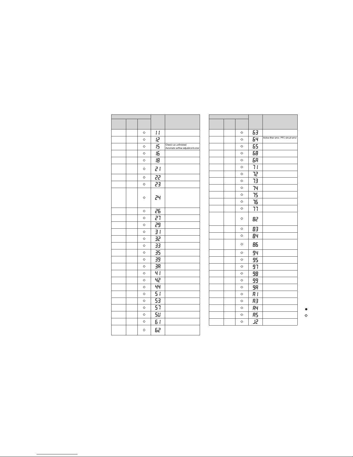
Error display
Wired
remote
controller
Error code
Description
OPERATION
lamp (green)
TIMER
lamp
(orange)
ECONOMY
lamp
(green)
(1)(1)
Serial communication error
(1)(2)
Wired remote controller
communication error
(1)(5)
(1)(6)
Peripheral unit transmission PCB
connection error
(1)(8)
External communication error
(2)(1)
Unit number or Refrigerant circuit
address setting error
[Simultaneous Multi]
(2)(2)
Indoor unit capacity error
(2)(3)
Combination error
(2)(4)
• Connection unit number
error (indoor secondary unit)
[Simultaneous Multi]
• Connection unit number error
(indoor unit or branch unit)
[Flexible Multi]
(2)(6)
Indoor unit address setting error
(2)(7)
Primary unit, secondary unit setup
error [Simultaneous Multi]
(2)(9)
Connection unit number error in
wired remote controller system
(3)(1)
Power supply interruption error
(3)(2)
Indoor unit PCB model
information error
(3)(3)
Indoor unit motor electricity
consumption detection error
(3)(5)
Manual auto switch error
(3)(9)
Indoor unit power supply error for
fan motor
(3)(10)
Indoor unit communication circuit
(wired remote controller) error
(4)(1)
Room temp. sensor error
(4)(2)
Indoor unit heat ex. middle temp.
sensor error
(4)(4)
Human sensor error
Error display
Wired
remote
controller
Error code
Description
OPERATION
lamp (green)
TIMER
lamp
(orange)
ECONOMY
lamp
(green)
(5)(1)
Indoor unit fan motor error
(5)(3)
Drain pump error
(5)(7)
Damper error
(5)(15)
Indoor unit error
(6)(1)
Outdoor unit reverse/missing
phase and wiring error
(6)(2)
Outdoor unit main PCB
model information error or
communication error
(6)(3)
Inverter error
(6)(4)
(6)(5)
Trip terminal L error
(6)(8)
Outdoor unit rush current limiting
resister temp. rise error
(6)(10)
Display PCB microcomputers
communication error
(7)(1)
Discharge temp. sensor error
(7)(2)
Compressor temp. sensor error
(7)(3)
Outdoor unit Heat Ex. liquid temp.
sensor error
(7)(4)
Outdoor temp. sensor error
(7)(5)
Suction Gas temp. sensor error
(7)(6)
• 2-way valve temp. sensor error
• 3-way valve temp. sensor error
(7)(7)
Heat sink temp. sensor error
(8)(2)
• Sub-cool Heat Ex. gas inlet
temp. sensor error
• Sub-cool Heat Ex. gas outlet
temp. sensor error
(8)(3)
Liquid pipe temp. sensor error
(8)(4)
Current sensor error
(8)(6)
• Discharge pressure sensor error
• Suction pressure sensor error
• High pressure switch error
(9)(4)
Trip detection
(9)(5)
Compressor rotor position
detection error (permanent stop)
(9)(7)
Outdoor unit fan motor 1 error
(9)(8)
Outdoor unit fan motor 2 error
(9)(9)
4-way valve error
(9)(10)
Coil (expansion valve) error
(10)(1)
Discharge temp. error
(10)(3)
Compressor temp. error
(10)(4)
High pressure error
(10)(5)
Low pressure error
(13)(2)
Branch boxes error
[Flexible Multi]
Page 10

1
4 Pipe Thermistor
Ref. Description
Part number
9900892005
2 Hose Sub Assy 9378450196
1 Remote Control
(no brand)
9709335055
3
4
3 Room Thermistor 9703299278
Control box
cover sub assy
Hook metal
2016.02.17
PARTS
INDOOR UNIT
ARYG12LHTBP
ARYG14LHTBP
9
2
Top panel sub assy
FUJI 用のリモコンですが、
欧州の在庫を減らすために、
FUJITSU,GENERALも
ブランドロゴの無いリモコンで供給します
Page 11

14 Power Supply PCB
15 Reactor Assy
Ref. Description
Part number
9710032028
9900921019
11 Main PCB (12LHTBP)
16 Terminal (Remote)
17 Terminal (Power)
9900896003
9900568009
9710016288
11 Main PCB (14LHTBP) 9710016295
12 Holder 0600063023
13 Communication PCB 9710019005
2016.02.17
INDOOR UNIT
ARYG12LHTBP
ARYG14LHTBP
10
15
17
16
14
13
12
11
Page 12

27 Drain Port
Drain pump
panel sub assy
Ref. Description Part number
9381565009
28 Drain Cap 9381578009
Drain hose
cover
Main panel sub assy
24 Float Switch
Window panel
sub assy
22 Drain Pan Sub Assy 9381752034
Pipe panel
sub assy
23 Drain Pump Sub Assy 9381766017
9900465070
25 Pump Assy 9900890018
26 Drain Hose 9381576005
21
Evaporator Total Assy (12)
9374517428
21
Evaporator Total Assy (14)
9374517411
2016.02.17
INDOOR UNIT
ARYG12LHTBP
ARYG14LHTBP
11
23
22
21
24
25
27
26
28
Page 13

Ref. Description Part number
31
33 Fan Motor
31 Casing B Sub Assy 9381829002
32 Sirocco Fan Assy 9381302000
34 Casing A 9381587001
Service panel
9603514006
2016.02.17
INDOOR UNIT
ARYG12LHTBP
ARYG14LHTBP
12
33
32
34
Page 14

PARTS
OUTDOOR UNIT
AOYG12LBLA
AOYG14LBLA
132016.02.18
3 Top Panel Assy
Outdoor Thermistor
1 Protective Net
7 Cabinet Right Assy
6 Switch Cover Assy
Parts numberDescriptionRef
9309230057
9900820008
9315319036
9309236059
9309237032
2
8 Fan Motor 9601725015
9 Propeller Fan 9309909014
5 Cabinet Assy 9312799404
10 Nut with Washer 9304902003
11 Drain Assy 9303029015
4 Fan Guard Cover 9378110014
Adaptor D (12 only)12 9370244007
3
11
1
2
7
6
9
4
5
10
8
12
Page 15

OUTDOOR UNIT
AOYG12LBLA
AOYG14LBLA
14
Parts numberDescriptionRef
2016.02.18
25 Heat Sink B
Main PCB (Service unit) (14)
22 PCB Holder
23 Terminal
Sealed panel
Terminal bracket
24 Heat Sink A
9314090011
9709681206
9313074029
9703874031
9314410017
21
Main PCB (Service unit) (12)
970968119021
25
21
22
23
24
Page 16

OUTDOOR UNIT
AOYG12LBLA
AOYG14LBLA
15
32
Parts numberDescriptionRef
41 2-way Valve Assy 9970093012
33 Pulse Motor Valve Assy
39 Compressor Assy 9313763039
31 Reactor Assy 9900641016
42 3-way Valve Assy 9970092015
34 Expansion Valve Coil
36 Thermistor Assy 9900818005
38 Solenoid 9970033018
Condenser Total Assy
37 4-way Valve Assy
2016.02.18
9315311030
40 Compressor Thermistor 9900819002
9311641018
9311381068
35
Heat Exchanger Thermistor
9900821005
9970095030
32
34
41
35
42
33
31
40
39
37
38
36
Page 17

Parts Q’ty Parts Q’ty Parts Q’ty
162016.02.18
INDOOR UNIT
Parts Q’ty
OUTDOOR UNIT
ACCESSORIES
(AOYG12LBLA only)
1
1
For drain piping work
Drain pipe
9303029015
Adapter assy
9370244007
Special nut A
(large flange)
4
For suspending the indoor unit
from ceiling
For suspending the indoor unit
from ceiling
For suspending the indoor unit
from ceiling
Special nut B
(small flange)
4
Washer
8
Coupler heat
insulation (large)
1
For indoor side
pipe joint (gas pipe)
For fixing the remote
control cable
For fixing the remote
control cable
Coupler heat
insulation (small)
1
For indoor side
pipe joint (liquid pipe)
For fixing the heat insulation
Cable tie (large)
4
Cable tie (medium)
1
Cable tie (small)
1
Remote control
(WEC type)
1
For air conditioner operation
Remote control accessories
1 set
See installation manual
for remote control
Drain hose insulation
1
Insulates the drain
hose and vinyl hose
Drain hose
1
For installing drain pipe
VP25 (O.D.32, I.D.25)
Hose Band
1
For installing drain hose
Page 18

1602G4485
 Loading...