

Page 1
SPLIT TYPE
AIR CONDITIONER
CASSETTE
Models
Indoor unit Outdoor unit
type (50Hz)
AUY12AGA AOY12AGAL
AUY12RGA AOY12RGAL
AUG12AGA AOG12AGAL
AUG12RGA AOG12RGAL
AUT12AGA AOT12AGAL
AUT12RGA AOT12RGAL
AUY14AGA AOY14AGAL
AUY14RGA AOY14RGAL
AUG14AGA AOG14AGAL
AUG14RGA AOG14RGAL
AUT14AGA AOT14AGAL
AUT14RGA AOT14RGAL
AUY18AGA AOY18ANCL
AUY18RGA AOY18RNCL
AUG18AGA AOG18ANCL
AUG18RGA AOG18RNCL
AUT18AGA AOT18ANCL
AUT18RGA AOT18RNCL
CONTENTS
SPECIFICATIONS
OUTLINE AND DIMENSIONS
CIRCUIT DIAGRAM
REFRIGERANT SYSTEM DIAGRAM
ERROR CONTENTS
INDOOR PCB CIRCUIT DIAGRAM
DISASSEMBLY ILLUSTRATION
PARTS LIST
. . . . . . . . . . . . . . . . . . . .
. . . . . . . . . .
. . . . . . . . . . . . . . . . . .
. . . . . . . . . . . . . . . . .
. . . . . . .
. . . . . . . . . . . . . . . . . . . . . . .
. . . .
. . . .
1
3
5
8
10
11
15
24
Page 2
SPECIFICATIONS
TYPE COOL COOL & HEAT COOL COOL & HEAT COOL COOL & HEAT
INDOOR UNIT
OUTDOOR UNIT
COOLING CAPACITY (kW) 3.65 - 3.70 3.60 - 3.65 4.00 - 4.10 3.90 - 4.00 4.95 - 5.10 4.85 - 5.00
HEATING CAPACITY (kW) --------- 4.00 - 4.10 --------- 4.50 - 4.70 --------- 5.30 - 5.45
ELECTRICAL DATA
POWER SOURCE (V) 220 - 240V
FREQUENCY (Hz) 50
RUNNING CURRENT (A)
INPUT WATTS (kW)
E.E.R. (kW/kW)
STARTING CURRENT (A) 29 29 41 41 42 42
MOISTURE REMOVAL (R /hr) 1.6 1.6 1.8 1.8 2.1 2.1
AIR CIRCULATION-Hi (m3/hr) 550 550 550 550 650 650
REFRIGERANT R-22 (g) 950 950 1,000 950 1,450 1,600
COOLING 5.8 - 5.5 5.9 - 5.5 7.4 - 7.4 7.4 - 7.4 8.7 - 8.5 8.2 - 8.0
HEATING --------- 5.8 - 5.5 --------- 7.4 - 7.4 ---------
COOLING 1.27 - 1.30 1.27 - 1.30 1.55 - 1.60 1.55 - 1.60 1.90 - 2.00 1.80 - 1.90
HEATING --------- 1.25 - 1.28 --------- 1.55 - 1.65 --------- 1.90 - 2.00
COOLING 2.87 - 2.85 2.83 - 2.81 2.58 - 2.56 2.52 - 2.50 2.61 - 2.55 2.69 - 2.68
HEATING --------- 3.20 - 3.20 --------- 2.90 - 2.85 --------- 2.79 - 2.73
AUY12AGA AUY12RGA AUY14AGA AUY14RGA AUY18AGA AUY18RGA
AUG12AGA AUG12RGA AUG14AGA AUG14RGA AUG18AGA AUG18RGA
AOG12AGAL AOG12RGAL AOG14AGAL AOG14RGAL AOG18ANCL AOG18RNCL
AOY12AGAL AOY12RGAL AOY14AGAL AOY14RGAL AOY18ANCL AOY18RNCL
8.4 - 8.5
COMPRESSOR
TYPE Hermetic type
DISCRIMINATION
POWER SOURCE
QJ236PD24B QJ282PC24A 2JS318D5BA02
220 - 240V 50Hz 220 - 240V 50Hz 220 - 240V 50Hz
FAN MOTOR
POWER SOURCE (V) 240
INDOOR UNIT
OUTDOOR UNIT
DISCRIMINATION MFA-14GTT MFA-18GTT
HI-SPEED (r.p.m.) 750 750 820
MED-SPEED (r.p.m.) 670 670 740
LO-SPEED (r.p.m.) 590 590 620
DISCRIMINATION
HI / LO (r.p.m.) 580 / 280 580 / 280 740 / 280
MFA-14GTT
MFB-14DTT MFB-14DTT MFB-252TAT
DIMENSIONS
INDOOR UNIT 235 x 580 x 580 + 70
OUTDOOR UNIT H x W x D
GRILLE 35 x 650 x 650
H x W x D
H x W x D
(mm)
(mm)
(mm)
643 x 840 x 336
WEIGHT
INDOOR UNIT 18 / 23
OUTDOOR UNIT GROSS / NET
GRILLE 2.2 / 4.3
GROSS / NET
GROSS / NET
(kg)
(kg)
(kg)
51 / 59 52 / 60 51 / 59 52 / 60 59 / 67 68 / 76
2003.06.25
ADDITIONAL REFRIGERANT CHARGE
PIPE LENGTH
FULLCHARGE AMOUNT
Additional refrigerant
5 m (16 ft)
10 m (33 ft)
15 m (49 ft)
20 m (66 ft)
g / m (oz. / ft)
950 g (33.5 oz)
1,000 g (35.3 oz)
1,050 g (37.0 oz)
1,110 g (38.8 oz)
10 (0.35)
1,000 g (35.3 oz)
1,075 g (37.9 oz)
1,150 g (40.6 oz)
1,225 g (43.2 oz)
15 (0.53)
1
1,000 g (35.3 oz)
1,050 g (37.0 oz)
1,100 g (38.8 oz)
1,150 g (40.6 oz)
10 (0.35)
1,000 g (35.3 oz)
1,075 g (37.9 oz)
1,150 g (40.6 oz)
1,225 g (43.2 oz)
15 (0.53)
1,170 g (41.3 oz)
1,245 g (43.9 oz)
1,320 g (46.6 oz)
1,395 g (49.2 oz)
15 (0.53)
1,800 g (63.5 oz)
1,950 g (68.8 oz)
2,100 g (74.1 oz)
2,250 g (79.4 oz)
30 (1.06)
Page 3
TYPE COOL COOL & HEAT COOL COOL & HEAT COOL COOL & HEAT
INDOOR UNIT
OUTDOOR UNIT
COOLING CAPACITY [W(A)] 3,700 3,650 4,100 4,000 5,100 5,000
HEATING CAPACITY [W(A)] --------- 4,100 --------- 4,700 --------- 5,450
AUT12AGA AUT12RGA AUT14AGA AUT14RGA AUT18AGA AUT18RGA
AOT12AGAL AOT12RGAL AOT14AGAL AOT14RGAL AOT18ANCL AOT18RNCL
ELECTRICAL DATA
POWER SOURCE (V) 240 - (220)
FREQUENCY (Hz) 50
RUNNING CURRENT (A)
INPUT WATTS (W)
E.E.R. (kW/kW)
STARTING CURRENT (A) 29 29 41 41 42 42
MOISTURE REMOVAL (R /hr) 1.6 1.6 1.8 1.8 2.1 2.1
AIR CIRCULATION-Hi (m3/hr) 550 550 550 550 650 650
REFRIGERANT R-22 (g) 950 950 1,000 950 1,450 1,600
COOLING
HEATING ---------
COOLING 1,300 1,300 1,600 1,600 2,000 1,900
HEATING --------- 1,280 --------- 1,650 --------- 2,000
COOLING 2.85 2.81 2.56 2.50 2.55 2.63
HEATING --------- 3.20 --------- 2.85 --------- 2.73
5.5 5.5 7.4 7.4
5.5
---------
7.4
8.5 8.0
---------
8.5
COMPRESSOR
TYPE Hermetic type
DISCRIMINATION
POWER SOURCE
QJ236PD24B QJ282PC24A 2JS318D5BA02
240 - (220) 50Hz 240 - (220) 50Hz 240 - (220) 50Hz
FAN MOTOR
POWER SOURCE (V) 240
MFA-14GTT MFA-18GTT
MFB-14DTT MFB-252TAT
INDOOR UNIT
OUTDOOR UNIT
DISCRIMINATION
HI-SPEED (r.p.m.) 750 750 820
MED-SPEED (r.p.m.) 670 670 740
LO-SPEED
DISCRIMINATION MFB-14DTT
HI / LO (r.p.m.) 580 / 280 580 / 280 740 / 280
(r.p.m.)
MFA-14GTT
590 590 620
DIMENSIONS
INDOOR UNIT 235 x 580 x 580 + 70
OUTDOOR UNIT H x W x D (mm)
GRILLE 35 x 650 x 650
H x W x D (mm)
643 x 840 x 336
H x W x D (mm)
WEIGHT
INDOOR UNIT
OUTDOOR UNIT GROSS / NET
GRILLE
GROSS / NET
GROSS / NET
(kg)
(kg)
(kg)
18 / 23
51 / 59 52 / 60 51 / 59 52 / 60 66 / 73 68 / 76
2.2 / 4.3
ADDITIONAL REFRIGERANT CHARGE
PIPE LENGTH
FULLCHARGE AMOUNT
Additional refrigerant
5 m (16 ft)
10 m (33 ft)
15 m (49 ft)
20 m (66 ft)
g / m (oz. / ft)
950 g (33.5 oz)
1,000 g (35.3 oz)
1,050 g (37.0 oz)
1,110 g (38.8 oz)
10 (0.35)
1,000 g (35.3 oz)
1,075 g (37.9 oz)
1,150 g (40.6 oz)
1,225 g (43.2 oz)
15 (0.53)
1,000 g (35.3 oz)
1,050 g (37.0 oz)
1,100 g (38.8 oz)
1,150 g (40.6 oz)
10 (0.35)
1,000 g (35.3 oz)
1,075 g (37.9 oz)
1,150 g (40.6 oz)
1,225 g (43.2 oz)
15 (0.53)
1,170 g (41.3 oz)
1,245 g (43.9 oz)
1,320 g (46.6 oz)
1,395 g (49.2 oz)
15 (0.53)
1,800 g (63.5 oz)
1,950 g (68.8 oz)
2,100 g (74.1 oz)
2,250 g (79.4 oz)
30 (1.06)
2003.06.25
2
Page 4
2003.06.25
- 3 -
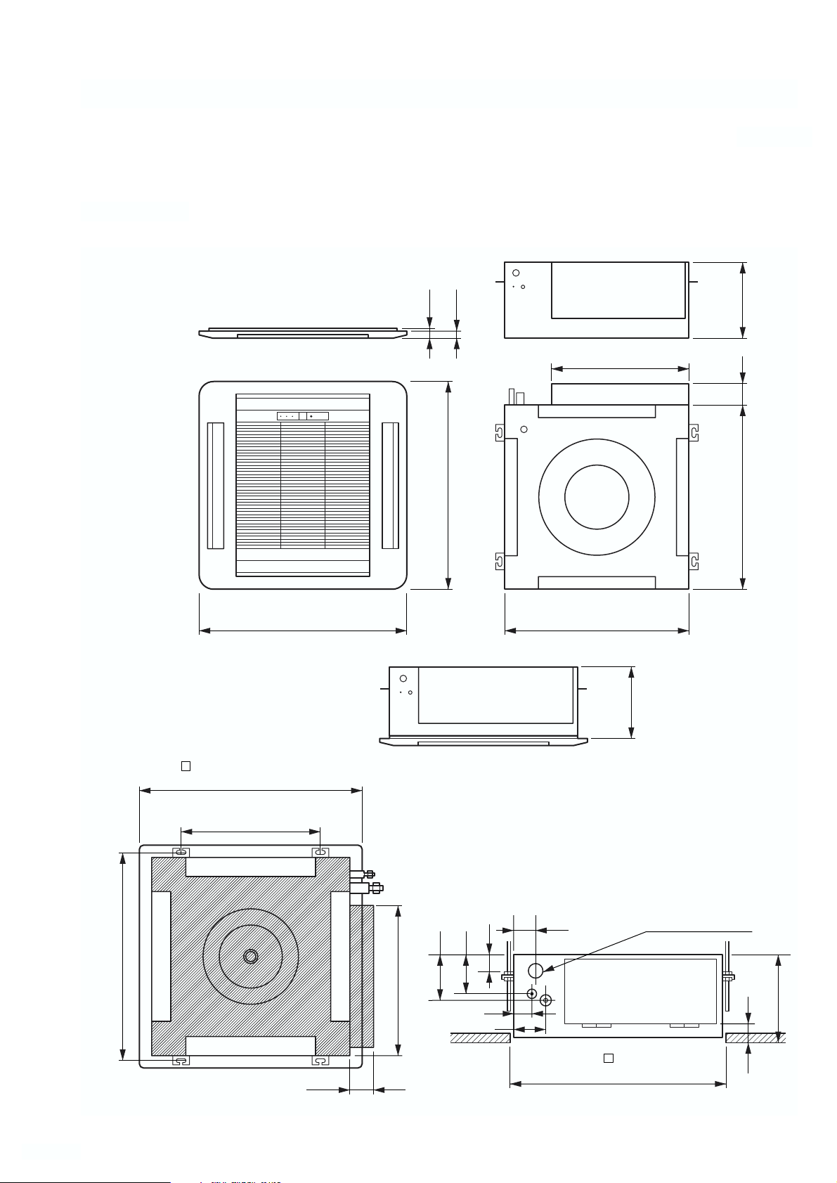
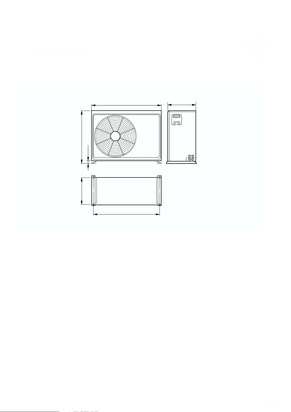
OUTLINE AND DIMENSIONS
(unit : mm)
INDOOR UNIT
35
20
650
235
440
580 66
580650
250
( 650) (Grille measurement)
(Hanging bolt position)
606
(Hanging bolt position)
650
400
66
440
131
111
47
46
86
60
600
(Ceiling opening measurement)
Drain pipe (I.D. ø32)
250
54
Page 5
2003.06.25
- 4 -
(unit : mm)
OUTDOOR UNIT
840
804
333
643
25
336
Page 6
Models : AUY12RGA / AOY12RGAL, AUG12RGA / AOG12RGAL, AUT12RGA / AOT12RGAL,
AUY14RGA / AOY14RGAL, AUG14RGA / AOG14RGAL, AUT14RGA / AOT14RGAL
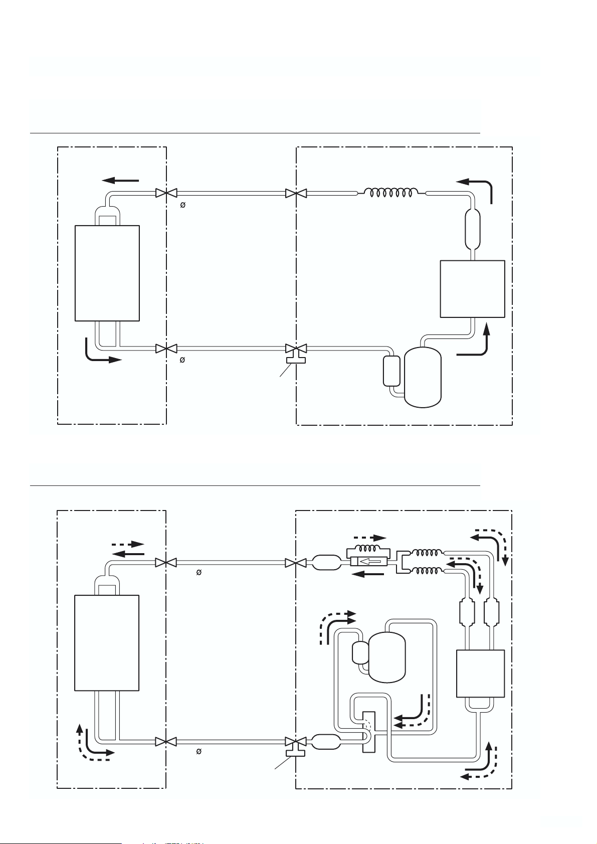
Models : AUY12AGA / AOY12AGAL, AUG12AGA / AOG12AGAL, AUT12AGA / AOT12AGAL,
AUY14AGA / AOY14AGAL, AUG14AGA / AOG14AGAL, AUT14AGA / AOT14AGAL,
AUY18AGA / AOY18ANCL, AUG18AGA / AOG18ANCL, AUT18AGA / AOT18ANCL
- 8 -
REFRIGERANT SYSTEM DIAGRAM
2003.06.25
OUTDOOR UNITINDOOR UNIT
Refrigerant pipe
6.35mm(1/4")
Evaporator
Refrigerant pipe
12.7mm(1/2")
Charging valve
Capillary tube
Dryer
Condenser
Compressor
Distributor
Evaporator
Refrigerant pipe
6.35mm(1/4")
Refrigerant pipe
12.7mm(1/2")
Charging valve
Dryer
Muffler
Compressor
4-Way
valve
OUTDOOR UNITINDOOR UNIT
Capillary tube
Strainer
Condenser
Strainer
Page 7
- 9 -
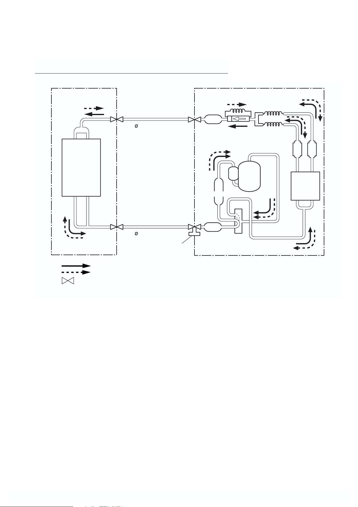
Models : AUY18RGA / AOY18RNCL, AUG18RGA / AOG18RNCL,
AUT18RGA / AOT18RNCL
2003.06.25
OUTDOOR UNITINDOOR UNIT
Distributor
Evaporator
: Flare coupling
Cooling
Heating
Refrigerant pipe
6.35mm(1/4")
Refrigerant pipe
12.7mm(1/2")
Charging valve
Dryer
Accumulator
Muffler
4-Way
valve
Capillary tube
Compressor
Strainer
Condenser
Strainer
Page 8
2003.06.25
- 5 -
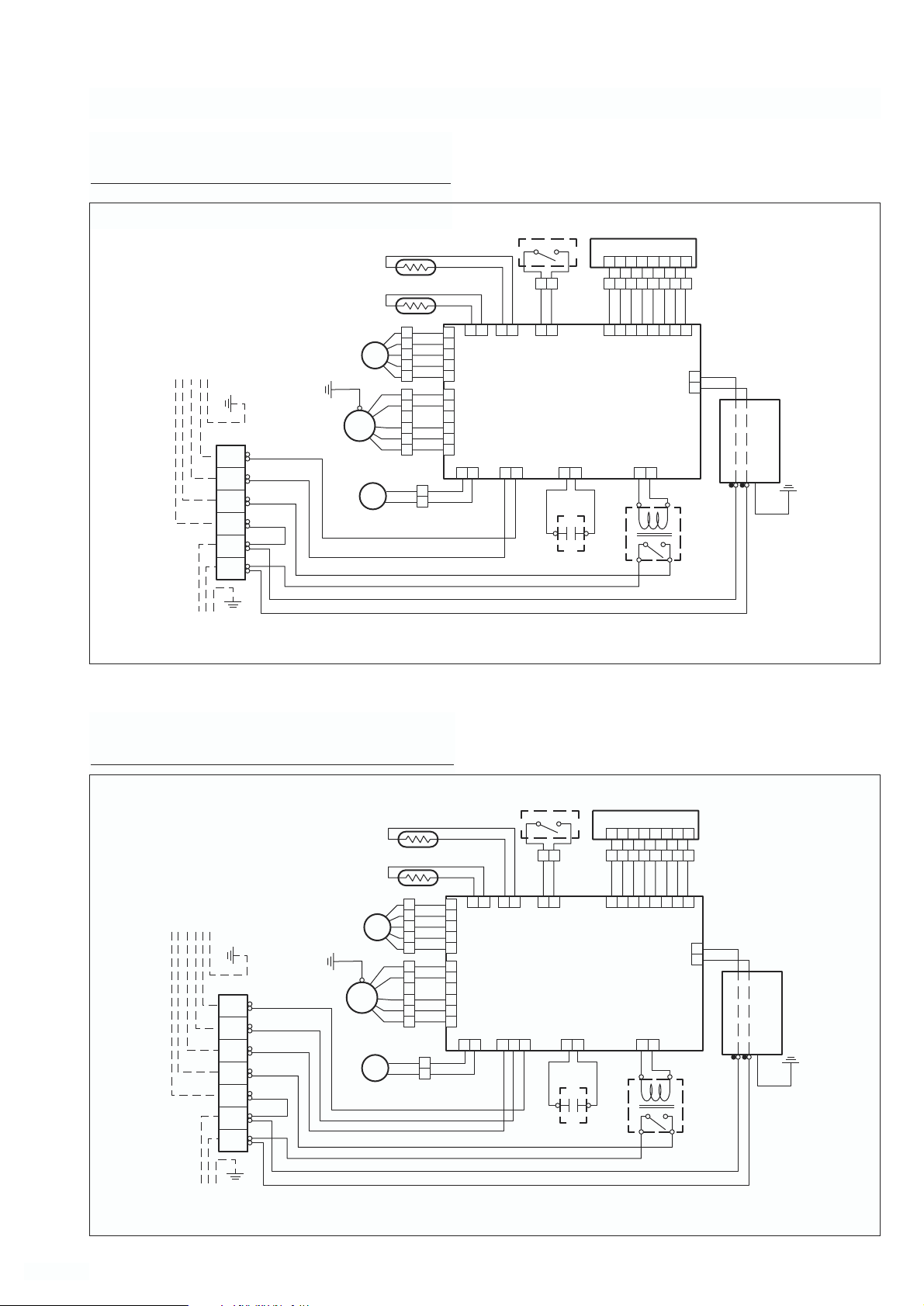
CIRCUIT DIAGRAM
Models : AUY12AGA, AUG12AGA, AUT12AGA,
AUY14AGA, AUG14AGA, AUT14AGA,
AUY18AGA, AUG18AGA, AUT18AGA
Models : AUY12RGA, AUG12RGA, AUT12RGA,
AUY14RGA, AUG14RGA, AUT14RGA,
AUY18RGA, AUG18RGA, AUT18RGA
THERMISTOR (ROOM TEMP.)
THERMISTOR (PIPE TEMP.)
WHITE
5
YELLOW
4
ORANGE
3
M
RED
2
BROWN
1
BLUE
1
PURPLE
2
5
RED
3
WHITE
6
BLACK
4
YELLOW
BLACK
1
YELLOW
BLACK
2
BLACK
WHITE
TO OUTDOOR UNIT
TERMINAL
4
3
2
1
(N)
N
L
POWER SUPPLY
WHITE
STEP
MOTOR
GREEN/YELLOW
FAN
MOTOR
DRAIN PUMP
FM
MOTOR
M
CN201
BLACK
BLACK
GRAY
GRAY
21
CN10
CN5
CN6
CN7
21
1
CN15
CN2
5
4
3
2
1
1
2
3
4
5
6
31
FLOAT
SWITCH
BLACK
BLACK
31
2
CN15
CONTROL BOARD
12
CN4
WHITE
FAN MOTOR
CAPACITOR
1 2 3 4 5 6 7 8
1 2 3 4 5 6 7 8
BROWN
1 2 3 4 5 6 7 8
12
WHITE
DISPLAY BOARD
RED
ORANGE
YELLOW
WHITE
BLUE
CN13
CN12
13
RED
RED
BLACK
BLACK
PURPLE
CN1
WHITE
BLACK
GRAY
2
1
MAIN
RELAY
WHITE
BLACK
Use T3.15A…250V
Fuse on F101
FILTER
BOARD
LN
GREEN
THERMISTOR (ROOM TEMP.)
THERMISTOR (PIPE TEMP.)
WHITE
5
YELLOW
4
TO OUTDOOR UNIT
TERMINAL
5
4
3
2
1
(N)
N
L
POWER SUPPLY
WHITE
MOTOR
FAN
MOTOR
STEP
GREEN/YELLOW
FM
DRAIN PUMP
MOTOR
M
ORANGE
3
M
RED
2
BROWN
1
BLUE
1
PURPLE
2
5
RED
3
WHITE
6
BLACK
4
YELLOW
BLACK
1
YELLOW
BLACK
2
RED
BROWN
BLUE
CN201
BLACK
BLACK
GRAY
GRAY
21
5
CN10
CN15
CN7
4
3
2
1
1
2
CN5
3
4
5
6
CN6
CN2
21
31
FLOAT
SWITCH
BLACK
BLACK
31
21
CN15
CONTROL BOARD
CN4
123
WHITE
FAN MOTOR
CAPACITOR
1 2 3 4 5 6 7 8
1 2 3 4 5 6 7 8
BROWN
1 2 3 4 5 6 7 8
12
WHITE
BLACK
BLACK
DISPLAY BOARD
RED
ORANGE
YELLOW
WHITE
BLUE
PURPLE
CN13
CN12
13
RED
RED
WHITE
BLACK
GRAY
CN1
2
1
MAIN
RELAY
WHITE
BLACK
Use T3.15A…250V
Fuse on F101
FILTER
BOARD
LN
GREEN
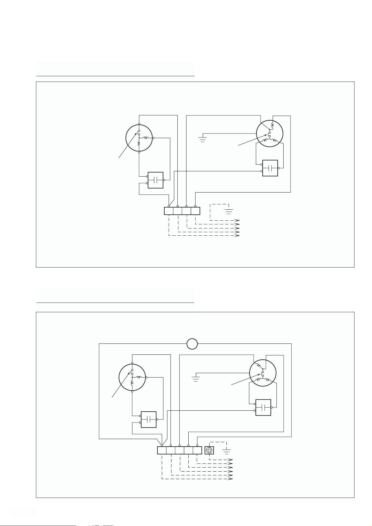
Page 9

Models : AOY12RGAL, AOG12RGAL,
AOT12RGAL
2003.06.25
- 6 -
Models : AOY12AGAL, AOG12AGAL,
AOT12AGAL
OVERLORD
PROTECTOR
COMPRESSOR
C
R
S
RED
BLACK
WHITE
COMPRESSOR
CAPACITOR
WHITE
WHITE
THERMAL
PROTECTOR
BLUE
RED
WHITE
FAN MOTOR
CAPACITOR
FAN MOTOR
BLACK
TERMINAL
OVERLORD
PROTECTOR
COMPRESSOR
C
R
S
RED
BLACK
WHITE
1(N) 2 3 4
COMPRESSOR
CAPACITOR
RED
WHITE
WHITE
TO INDOOR UNIT
THERMAL
PROTECTOR
BLUE
WHITE
FAN MOTOR
CAPACITOR
FAN MOTOR
BLACK
4 WAY VALVE
BLACK
BLACK
SV
TERMINAL
1(N) 2 3 4 5
TO INDOOR UNIT
Page 10
Models : AOY14RGAL, AOG14RGAL, AOT14RGAL,
AOY18RNCL, AOG18RNCL, AOT18RNCL
Models : AOY14AGAL, AOG14AGAL, AOT14AGAL,
AOY18ANCL, AOG18ANCL, AOT18ANCL
- 7 -
2003.06.25
BLACK
COMPRESSOR C
S
R
INTERNAL
OVERLORD
PROTECTOR
COMPRESSOR
CAPACITOR
WHITE
TERMINAL
RED
WHITE
321(N)
4
RED
YELLOW/GREEN
WHITE
BLUE
FAN MOTOR
THERMAL
PROTECTOR
WHITE
FAN MOTOR
CAPACITOR
TO INDOOR UNIT
BLACK
COMPRESSOR C
INTERNAL
OVERLORD
PROTECTOR
COMPRESSOR
CAPACITOR
WHITE
BLACK
R
WHITE
BLACK
TERMINAL
4 WAY VALVE
SV
RED
FAN MOTOR
4
YELLOW/GREEN
WHITE
BLUE
THERMAL
PROTECTOR
BLACK
WHITE
FAN MOTOR
CAPACITOR
TO INDOOR UNIT
BLACK
S
RED
3 521(N)
Page 11

INDOOR PCB CIRCUIT DIAGRAM
Models : AUY12AGA, AUG12AGA, AUT12AGA,
AUY14AGA, AUG14AGA, AUT14AGA
CONTROLLER PCBASSEMBLY ( MAIN PCB )
EZ-097EWSE-C
1.0uF
370V
2003.06.25
- 11 -
Page 12

2003.06.25
- 12 -
Models : AUY12RGA, AUG12RGA, AUT12RGA,
AUY14RGA, AUG14RGA, AUT14RGA
CONTROLLER PCB ASSEMBLY ( MAIN PCB )
EZ-097HHSE-C
Page 13

2003.06.25
- 13 -
Models : AUY18AGA, AUG18AGA, AUT18AGA
CONTROLLER PCB ASSEMBLY ( MAIN PCB )
EZ-097EWSE-C
Page 14

2003.06.25
- 14 -
Models : AUY18RGA, AUG18RGA, AUT18RGA
CONTROLLER PCB ASSEMBLY ( MAIN PCB )
EZ-097HHSE-C
Page 15

2003.06.25
- 10 -
Models : AUY12AGA / AOY12AGAL, AUG12AGA / AOG12AGAL, AUT12AGA / AOT12AGAL,
AUY14AGA / AOY14AGAL, AUG14AGA / AOG14AGAL, AUT14AGA / AOT14AGAL,
AUY18AGA / AOY18ANCL, AUG18AGA / AOG18ANCL, AUT18AGA / AOT18ANCL
ERROR CONTENTS
• Run the air conditioner in accordance with the
operating manual.
• Press the remote control unit, test run button while
the air conditioner is running.
• At the end of test running, press the remote control
unit start/stop button.
Operation can be checked by lighting and flashing of
the grille display section OPERATION and TIMER
lamps.
Perform judgment in accordance with the following.
CHECK ITEMS
1. INDOOR UNIT
(1) Is operation of each button on the remote control
unit normal?
(2) Does each lamp light normally?
(3) Do not air flow direction louvers operate normally?
(4) Is the drain normal?
(5) Is there any abnormal noise and vibration during
operation?
2. OUTDOOR UNIT
(1) Is there any abnormal noise and vibration during
operation?
(2) Will noise, wind or drain water from the unit disturb
the neighbors?
(3) Is there any gas leakage?
• Do not operate the air conditioner in the test
running state for a long time.
• For the operation method, refer to the operating
manual and perform operation check.
• Test running
When the air conditioner is run by pressing the
remote controller test run button, the OPERATION
and TIMER lamps flash slowly at the same time.
• Error
The OPERATION and TIMER lamps operate as
follows (Table) according to the error contents.
Table
OPERATION LAMP
(Red)
TIMER LAMP
(Green)
SWING LAMP
(Orange)
START/STOP
button
TEST RUN
button
OPERATION
LAMP
ON
TIMER
LAMP
OPERATION
LAMP
TIMER
LAMP
OPERATION
LAMP
TIMER
LAMP
OFF
ON
OFF
ON
OFF
ON
OFF
ON
OFF
Error display Error contents
0.5 sec 0.5 sec
ON
OFF
0.1 sec
0.1 sec
0.5 sec
0.1 sec
0.1 sec
0.5 sec 0.5 sec
5 sec
0.1 sec
0.1 sec
5 sec
5 sec
Two quick
flashes
repeated
0.1 sec
ON/OFF
repeated
0.5 sec
Three quick
flashes
repeated
0.1 sec
ON/OFF
repeated
Four quick
flashes
repeated
0.1 sec
ON/OFF
repeated
Room temperature
thermistor
abnormal
temperature
detected
Piping thermistor
abnormal
temperature
detected
Float switch
ON for 3 minutes
or longer
SWING TIMER OPERATION
MANUAL
AUTO
Page 16

2003.06.25
- 15 -
DISASSEMBLY ILLUSTRATION
484
Models : AUY12AGA, AUG12AGA, AUT12AGA,
AUY14AGA, AUG14AGA, AUT14AGA,
AUY18AGA, AUG18AGA, AUT18AGA,
AUY12RGA, AUG12RGA, AUT12RGA,
AUY14RGA, AUG14RGA, AUT14RGA,
AUY18RGA, AUG18RGA, AUT18RGA
462
464
467
244
797
465
479
478
138
338
411
465
834
287
313
798
484
835
127
836
482
196
965
187
117-3
967-2
964
470
235
495
67
164
147
232
652-1
411
146
395
240
743
476-3
475
476-2
476-1
469
468
399
184-1
474
457
488
160
430
301
234
Page 17

2003.06.25
- 16 -
210
34
514
629
824-3
875
236
381
381
815
989-1
628
989-2
381
628
381
287
185
223
Page 18

Models : UTG-UDYA-W,
UTG-UDGA-W
- 17 -
2003.06.25
417
165
694
691
690
226
196
692
876-2
705
763
692
416
416
417
392
690
385
705
691
690
392
758
776
710
777
691
711-1
690
692
700
776
711-2
93
Page 19

- 18 -
Models : AOY12AGAL, AOG12AGAL, AOT12AGAL,
AOY14AGAL, AOG14AGAL, AOT14AGAL,
AOY18ANCL, AOG18ANCL, AOT18ANCL,
AOY12RGAL, AOG12RGAL, AOT12RGAL,
AOY14RGAL, AOG14RGAL, AOT14RGAL,
AOY18RNCL, AOG18RNCL, AOT18RNCL
9
7
646
26
10
6
55
46
107
8
347
109
110
111
108
187
187
29
45
41
67
338
39
2
717
5
4
12
16
36-2
32-1
2003.06.25
Page 20

2003.06.25
- 19 -
Models : AOY12AGAL, AOG12AGAL, AOT12AGAL,
AOY14AGAL, AOG14AGAL, AOT14AGAL
20
18
15
14
13
46
54-2
Page 21

2003.06.25
- 20 -
Models : AOY12RGAL, AOG12RGAL, AOT12RGAL,
AOY14RGAL, AOG14RGAL, AOT14RGAL
334
271
360
20
343
15
a
14
13
18
910
910
54
54
333
838-2
829-2
Page 22

- 21 -
348-1
18
46
20
16
15
14
13
Models : AOY18ANCL, AOG18ANCL, AOT18ANCL
2003.06.25
Page 23

- 22 -
Models : AOY18RNCL, AOG18RNCL, AOT18RNCL
344
343
300
15
333
a
14
13
334
867
b
910
910
46
20
838-1
332-1
829-2
348-1
348-1
2003.06.25
271
360
Page 24

2003.06.25
- 23 -
Control Unit
815
34
187
37
38
36-2
32-1
Models : AOY12AGAL, AOG12AGAL, AOT12AGAL,
AOY14AGAL, AOG14AGAL, AOT14AGAL,
AOY18ANCL, AOG18ANCL, AOT18ANCL,
AOY12RGAL, AOG12RGAL, AOT12RGAL,
AOY14RGAL, AOG14RGAL, AOT14RGAL,
AOY18RNCL, AOG18RNCL, AOT18RNCL
Page 25

PARTS LIST
INDOOR UNIT
Ref.
Description
No.
34 Capacitor (Fan Motor) 9704305046 9704305046 9704305046 9704305046 9704305046 9703306044
67 Rubber 9361279001 9361279001 9361279001 9361279001 9361279001 9361279001
117-3 Special Washer M6 313306391007 313306391007 313306391007 313306391007 313306391007 313306391007
127 Drain Hose 9359659013 9359659013 9359659013 9359659013
138 Separate Wall -A 9359647003 9359647003 9359647003 9359647003
146 Evaporator Assy -IN 9360009012 9360009012 9360009012 9360009012 93606400179360640017
147 Inlet Pipe (Eva.) Assy 9360010018 9360010018 9360010018 9360010018 9360010018 9360010018
160 Drain Pan 9359651000 9359651000
164 Fan Motor Assy -IN 9601040019 9601040019 9601040019 9601040019 9601040026 9601040026
184-1 Thermo. Spring -A 313728262708 313728262708 313728262708313728262708 313728262708 313728262708
185 Rubber Bushing 313005066051 313005066051 313005066051 313005066051 313005066051 313005066051
187 Clamp No. 1219 313361271706 313361271706 313361271706 313361271706 313361271706 313361271706
196 Clamp SKB -150 313035356905 313035356905313035356905 313035356905 313035356905 313035356905
210 Main Relay 9356781007 9356781007 9356781007 9356781007 9356781007 9356781007
223 Control Box 9359661016 9359661016 9359661016 9359661016 9359661016 9359661016
232 Outlet Pipe (Eva.) Assy 9360011015 9360011015 9360011015 9360011015 9360011015 9360011015
234 Thermistor Assy -Room 9703299032 9703299032 9703299032 9703299032
235 Thermistor Assy -Pipe 9703297014 9703297014
236 Controller PCB Assy 9701941155 9701941131 9701941155 9701941131 9701941155 9701941193
240 Remote Control Unit 9359913047 9359913030 9359913047 9359913030 9359913047 9359913030
AUY12AGA
AUG12AGA
AUT12AGA
AUY12RGA
AUG12RGA
AUT12RGA
9359659013 9359659013
359647003 9359647003
9359651000 9359651000 9359651000 9359651000
9703299032 9703299032
9703297014 9703297014 9703297014 9703297014
AUY14AGA
AUG14AGA
AUT14AGA
Part No.
AUY14RGA
AUG14RGA
AUT14RGA
AUY18AGA
AUG18AGA
AUT18AGA
AUY18RGA
AUG18RGA
AUT18RGA
Ord.
Q'ty
244 Pipe Cover 9359646006 9359646006 9359646006 9359646006
287 Cap (Power) 9352173011 9352173011
301 Clamp NK -2N 313985355201 313985355201 313985355201 313985355201 313985355201 313985355201
313 Hooking Wire 9359983002 9359983002 9359983002 9359983002
338 Motor Fixture 9359656005 9359656005
381 Locking Spacer 313209391506 313209391506313209391506 313209391506 313209391506 313209391506
395 Supporter (Eva.) 9359669005 9359669005 9359669005 9359669005 9359669005 9359669005
399 Air Duct 9359660002 9359660002 9359660002 9359660002
411 Supporter -A 9359655008 9359655008 9359655008 9359655008
430 Clamp NK -7N 313095365602 313095365602
457 Drain Pan Support 9359652007 9359652007 9359652007 9359652007 9359652007 9359652007
462 Top Cover Plate 9359642015 9359642015 9359642015 9359642015 9359642015 9359642015
464 Body -A 9359643005 9359643005 9359643005 9359643005
465 Body -B 9359645009 9359645009 9359645009 9359645009
467 Drain Port 313005415658 313005415658
468 Special Nut -A (Large) 313005446653 313005446653 313005446653 313005446653 313005446653 313005446653
469 Special Nut -B (Small) 313005446759 313005446759 313005446759 313005446759 313005446759 313005446759
470 Separate Wall -B 9359648000 9359648000 9359648000 9359648000
474 Turbo Fan 9359658009 9359658009 9359658009 9359658009
475 Turbo Fan Rubber 9366013006 9366013006 9366013006 9366013006 9366013006 9366013006
476-1 Special Nut M8 313005360755 313005360755 313005360755 313005360755 313005360755 313005360755
476-2 Special Washer 301801185049 301801185049 301801185049 301801185049
476-3 Special Washer 9359954002 9359954002
478 Sensor M. Bracket 9359654001 9359654001 9359654001 9359654001 9359654001 9359654001
479 Float Switch 313005416154
482 Pump Unit 9359974000 9359974000 9359974000 9359974000
484 Hanger Metal 9359644002 9359644002
488 Drain Pan Plug 9359653004 9359653004 9359653004 9359653004 9359653004 9359653004
495 Clamp No. 2U46 9352715006 9352715006 9352715006 9352715006 9352715006 9352715006
514 Control Box Cover 9359662006 9359662006 9359662006 9359662006 9359662006 9359662006
9359646006 9359646006
9352173011 9352173011 9352173011 9352173011
9359983002 9359983002
9359656005 9359656005 9359656005 9359656005
9359660002 9359660002
9359655008 9359655008
313095365602 313095365602 313095365602 313095365602
9359643005 9359643005
9359645009 9359645009
313005415658 313005415658 313005415658 313005415658
9359648000
9359658009
301801185049 301801185049
9359954002 9359954002 9359954002 9359954002
313005416154 313005416154
9359974000 9359974000
9359644002 9359644002 9359644002 9359644002
9359648000
9359658009
313005416154 313005416154 313005416154
628 Locking Spacer -B 313005446558 313005446558 313005446558 313005446558 313005446558 313005446558
629 EMI Filter 0400197119 0400197119 0400197119 0400197119 0400197119 0400197119
652-1 Therm. Holder Pipe 313806262805 313806262805 313806262805 313806262805 313806262805 313806262805
743
Remote Control Holder Case
797 Separate Wall-C 9359649007 9359649007 9359649007 9359649007
798 Pump Hook Bracket 9359650003 9359650003 9359650003 9359650003 9359650003 9359650003
815 Terminal-7P 9358660102 9358660102 9358660102 9358660102
824-3 Fuse 0600222512 0600222512 0600222512 0600222512
834 Wire Cover 9359878001 9359878001 9359878001 9359878001
835 Cushion -A (For Pump) 9352211003 9352211003 9352211003 9352211003 9352211003 9352211003
836 Cushion -B (For Pump) 9356084016 9356084016 9356084016 9356084016 9356084016 9356084016
875 Filter PCB Assy 9702326012 9702326012 9702326012 9702326012 9702326012 9702326012
964 Flare Nut -A 313996239804 313996239804 313996239804 313996239804
965 Flare Nut -B 9351062019 9351062019 9351062019 9351062019
967-2 Bonnet -B 9301858006 93018580069301858006930185800693018580069301858006
989-1 Cord Clamp -A 9359822011 9359822011 9359822011 9359822011
989-2 Cord Clamp -B 9359823018
2005.11.14
9359955016 9359955016 9359955016 9359955016 9359955016
9359649007
9358660102
0600222512
9359878001
313996239804
9351062019
9359822011
9359823018 9359823018
24
9359955016
9359649007
9358660102
0600222512
9359878001
313996239804
9351062019
9359822011
9359823018 9359823018 9359823018
When you order parts, please make a photocopy of this page
and fill the number of the parts in the "Order" column.
Page 26

GRILLE ASSY
Ref.
No.
93 Filter 9359632009
165 Motor Cover 9359623014
196 Clamp SKB-150 313035356905
226 Motor Gear 9359629009
385 Indicator PCB Assy 9702224011
392 Cover-A
416 Insulation (Panel)-A 9359620006
417 Insulation (Panel)-B 9359621003
690 Joint-A
691 Joint-B
692 Joint Shaft 9359625001
694 Cam Gear 9359628002
700 Panel
705 Louver 9359624011
710 Intake Grille 9359631019
711-1 Filter Clamp-A 9359634003
711-2 Filter Clamp-B 9359635000
758 Decoration Plate 9360039026
763 Receiver Cover 9359630005
776 Grille Stopper 9359633013
777 Grille Hook 9359761006
876-2 Step Motor-V 9360307019
Description
UTG-UDYA-W UTG-UDGA-W
9359632009
9359623014
313035356905
9359629009
9702224011
9359622017
9359620006
9359621003
9359626008
9359627005
9359625001
9359628002
9359619017
9359624011
9359631019
9359634003
9359635000
9360039019
9359630005
9359633013
9359761006
9360307019
Part No.
9359622017
9359626008
9359627005
9359619017
Ord.
Q'ty
2005.11.14 25
When you order parts, please make a photocopy of this page
and fill the number of the parts in the "Order" column.
Page 27

OUTDOOR UNIT
Ref.
Description
No.
Part No.
AOY12AGAL
AOT12AGAL
AOY14AGAL
AOT14AGAL
Ord.
Q'ty
Ref.
No.
Description
Part No.
AOY12RGAL
AOT12RGAL
AOY14RGAL
AOT14RGAL
Ord.
Q'ty
2 Fan Cover 9350214020 9350214020
4 Emblem-Rear "FUJITSU" 9351355005 9351355005
5 Cabinet-A, Painted 9303876015 9303876015
6 Cabinet-C, Painted 9353549013 9353549013
7 Connector Cover 9358011010 9358011010
8 Wire Assy (Shield)-D ------ 9350215010
9 Cabinet-B, Painted 9303874011 9303874011
10 Noise Insulation-E 313791106305 313791106305
12 Base Assy, Painted 9353452054 9353452054
13 3-Way Valve Assy 9364524009 9364524009
14 2-Way Valve 9358023013 9358023013
15 Dryer 93681110149368111014
16 Condenser Assy 9353455055 9353455055
18 Suction Pipe 9371297026 9371297026
20 Discharge Pipe 9371298023 9371298023
26 Compressor Cover 9370184006 9370184006
29 Separate Wall 313986033213 313986033213
32-1 Control Box Metal-A 9365672013 9365672013
34 Capacitor (Fan Motor) 9357965024 9357965024
36-2 Cord Holder Metal 9356362008 9356362008
37 Running Capacitor 9357211084 9356386035
38 Capacitor Clamp 313468061808 313468061808
39 Propeller Fan Assy 9300855013 9300855013
41 Fan Motor Assy-Out 9600738061 9600738061
45 Motor Fixing Table Assy 313029311100 313029311100
46 Compressor Assy 9365866009 9364723006
54-2 Condensing Pipe Assy 9371378015 9371378015
55 Special Nut M8 (For Comp.) 9355091008 9355091008
67 Rubber 313659068604 313659068604
107 Rubber Seat-A (For Comp.) 9350425014 9350425014
108 Sleeve-A (For Comp.) 313093081706 313093081706
109 Terminal Cover (For Comp.) 9363263008 9364724003
2 Fan Cover 9350214020 9350214020
4 Emblem-Rear "FUJITSU" 9351355005 9351355005
5 Cabinet-A, Painted 9303876015 9303876015
6 Cabinet-C, Painted 9353549013 9353549013
7 Connector Cover 9358011010 9358011010
8 Wire Assy (Shield)-D ------ 9350215010
9 Cabinet-B, Painted 9303874011 9303874011
10 Noise Insulation-E 313791106305 313791106305
12 Base Assy, Painted 9353452054 9353452054
13 3-Way Valve Assy 9364524009 9364524009
14 2-Way Valve 9358023013 9358023013
15 Dryer 9368112011 9368112011
16 Condenser Assy 9360672018 9360672018
18 Suction Pipe 9371297019 9371297019
20 Discharge Pipe 9371298016 9371298016
26 Compressor Cover 9370184006 9370184006
29 Separate Wall 313986033213 313986033213
32-1 Control Box Metal-A 9365672013 9365672013
34 Capacitor (Fan Motor) 9357965024 9357965024
36-2 Cord Holder Metal 9356362008 9356362008
37 Running Capacitor 9357211084 9356386035
38 Capacitor Clamp 313468061808 313468061808
39 Propeller Fan Assy 9300855013 9300855013
41 Fan Motor Assy-Out 9600738061 9600738061
45 Motor Fixing Table Assy 313029311100 313029311100
46 Compressor Assy 9365866009 9364723006
54 Condensing Pipe 9360679000 9360679000
55 Special Nut M8 (For Comp.) 9355091008 9355091008
67 Rubber 313659068604 313659068604
107 Rubber Seat-A (For Comp.) 9350425014 9350425014
108 Sleeve-A (For Comp.) 313093081706 313093081706
109 Terminal Cover (For Comp.) 9363263008 9364724003
110 Lock Wire 313202059706 313202059706
111 Terminal Packing 313202059807 313202059807
187 Clamp No. 1219 313361271706 313361271706
338 Motor Fixture 313029297108 313029297108
347 Noise Insulation-D 313712304109 313712304109
646 Compressor Cover-B 313986355101 313986355101
717 Center Plate 9351253011 9351253011
815 Terminal-5P 9356497021 9356497021
--- Capillary Assy 9371377018 9371377018
2005.11.14 26
110 Lock Wire 313202059706 313202059706
111 Terminal Packing 313202059807 313202059807
187 Clamp No. 1219 313361271706 313361271706
271 4-Way Valve Rubber 313728251908 313728251908
333 Accumulator 9303037003 9303037003
338 Motor Fixture 313029297108 313029297108
343 Solenoid Coil 9704061010 9704061010
344 4-Way Valve 9307556012 9307556012
347 Noise Insulation-D 313712304109 313712304109
360 4-Way Valve Band 313986251802 313986251802
646 Compressor Cover-B 313986355101 313986355101
717 Center Plate 9351253011 9351253011
815 Terminal-5P 9356497021 9356497021
829-2 Joint Pipe (Valve) 9371296012 9371296012
838-2 Inlet Pipe Assy 9371299013 9371299013
910 Strainer 9350379026 9350379026
--- Capillary Assy 9371287010 9371287065
When you order parts, please make a photocopy of this page
and fill the number of the parts in the "Order" column.
Page 28

OUTDOOR UNIT
Ref.
Description
No.
Part No.
AOG12AGAL AOG14AGAL
Ord.
Q'ty
Ref.
No.
Description
Part No.
AOG12RGAL AOG14RGAL
Ord.
Q'ty
2 Fan Cover 9350214020 9350214020
4 Emblem-Rear "GENERAL" 313791088308 313791088308
5 Cabinet-A, Painted 9303876015 9303876015
6 Cabinet-C, Painted 9353549013 9353549013
7 Connector Cover 9358011010 9358011010
8 Wire Assy (Shield)-D ------ 9350215010
9 Cabinet-B, Painted 9303874011 9303874011
10 Noise Insulation-E 313791106305 313791106305
12 Base Assy, Painted 9353452054 9353452054
13 3-Way Valve Assy 9364524009 9364524009
14 2-Way Valve 9358023013 9358023013
15 Dryer 93681110149368111014
16 Condenser Assy 9353455055 9353455055
18 Suction Pipe 9371297026 9371297026
20 Discharge Pipe 9371298023 9371298023
26 Compressor Cover 9370184006 9370184006
29 Separate Wall 313986033213 313986033213
32-1 Control Box Metal-A 9365672013 9365672013
34 Capacitor (Fan Motor) 9357965024 9357965024
36-2 Cord Holder Metal 9356362008 9356362008
37 Running Capacitor 9357211084 9356386035
38 Capacitor Clamp 313468061808 313468061808
39 Propeller Fan Assy 9300855013 9300855013
41 Fan Motor Assy-Out 9600738061 9600738061
45 Motor Fixing Table Assy 313029311100 313029311100
46 Compressor Assy 9365866009 9364723006
54-2 Condensing Assy 9371378015 9371378015
55 Special Nut M8 (For Comp.) 9355091008 9355091008
67 Rubber 313659068604 313659068604
107 Rubber Seat-A (For Comp.) 9350425014 9350425014
108 Sleeve-A (For Comp.) 313093081706 313093081706
109 Terminal Cover (For Comp.) 9363263008 9364724003
2 Fan Cover 9350214020 9350214020
4 Emblem-Rear "GENERAL" 313791088308 313791088308
5 Cabinet-A, Painted 9303876015 9303876015
6 Cabinet-C, Painted 9353549013 9353549013
7 Connector Cover 9358011010 9358011010
8 Wire Assy (Shield)-D ------ 9350215010
9 Cabinet-B, Painted 9303874011 9303874011
10 Noise Insulation-E 313791106305 313791106305
12 Base Assy, Painted 9353452054 9353452054
13 3-Way Valve Assy 9364524009 9364524009
14 2-Way Valve 9358023013 9358023013
15 Dryer 9368112011 9368112011
16 Condenser Assy 9360672018 9360672018
18 Suction Pipe 9371297019 9371297019
20 Discharge Pipe 9371298016 9371298016
26 Compressor Cover 9370184006 9370184006
29 Separate Wall 313986033213 313986033213
32-1 Control Box Metal-A 9365672013 9365672013
34 Capacitor (Fan Motor) 9357965024 9357965024
36-2 Cord Holder Metal 9356362008 9356362008
37 Running Capacitor 9357211084 9356386035
38 Capacitor Clamp 313468061808 313468061808
39 Propeller Fan Assy 9300855013 9300855013
41 Fan Motor Assy-Out 9600738061 9600738061
45 Motor Fixing Table Assy 313029311100 313029311100
46 Compressor Assy 9365866009 9364723006
54 Condensing Pipe 9360679000 9360679000
55 Special Nut M8 (For Comp.) 9355091008 9355091008
67 Rubber 313659068604 313659068604
107 Rubber Seat-A (For Comp.) 9350425014 9350425014
108 Sleeve-A (For Comp.) 313093081706 313093081706
109 Terminal Cover (For Comp.) 9363263008 9364724003
110 Lock Wire 313202059706 313202059706
111 Terminal Packing 313202059807 313202059807
187 Clamp No. 1219 313361271706 313361271706
338 Motor Fixture 313029297108 313029297108
347 Noise Insulation-D 313712304109 313712304109
646 Compressor Cover-B 313986355101 313986355101
717 Center Plate 9351253011 9351253011
815 Terminal-5P 9356497021 9356497021
--- Capillary Assy 9371377018 9371377018
2005.11.14 27
110 Lock Wire 313202059706 313202059706
111 Terminal Packing 313202059807 313202059807
187 Clamp No. 1219 313361271706 313361271706
271 4-Way Valve Rubber 313728251908 313728251908
333 Accumulator 9303037003 9303037003
338 Motor Fixture 313029297108 313029297108
343 Solenoid Coil 9704061010 9704061010
344 4-Way Valve 9307556012 9307556012
347 Noise Insulation-D 313712304109 313712304109
360 4-Way Valve Band 313986251802 -----646 Compressor Cover-B 313986355101 313986355101
717 Center Plate 9351253011 9351253011
815 Terminal-5P 9356497021 9356497021
829-1 Joint Pipe (Valve) 9371296012 9371296012
838-2 Inlet Pipe Assy 9371299013 9371299013
910 Strainer 9350379026 9350379026
a Joint Pipe (Dryer) 9371295015 9371295015
--- Capillary Assy 9371287010 9371287065
When you order parts, please make a photocopy of this page
and fill the number of the parts in the "Order" column.
Page 29

OUTDOOR UNIT
Ref.
Description
No.
2 Fan Cover 9350214020
4 Emblem-Rear "FUJITSU" 9351355005
5 Cabinet-A, Painted 9303876015
6 Cabinet-C, Painted 9353549013
7 Connector Cover 9358011010
8 Wire Assy (Shield)-D 9370945027
9 Cabinet-B, Painted 9303874011
10 Noise Insulation-E 313791106305
12 Base Assy, Painted 9353452054
13 3-Way Valve Assy 9364524009
14 2-Way Valve 9358023013
15 Dryer 9368111014
16 Condenser Assy 9353455055
18 Suction Pipe 9371297026
26 Compressor Cover 9363020007
29 Separate Wall 313986033213
32-1 Control Box Metal-A 9365672013
34 Capacitor (Fan Motor) 9357965024
36-2 Cord Holder Metal 9356362008
37 Running Capacitor 9704436023
38 Capacitor Clamp 9351770013
39 Propeller Fan Assy 9300855013
41 Fan Motor Assy-Out 9600738047
45 Motor Fixing Table Assy 313029311100
Part No.
AOY18ANCL
AOT18ANCL
Ord.
Q'ty
Ref.
Description
No.
2 Fan Cover 9350214020
4 Emblem-Rear "FUJITSU" 9351355005
5 Cabinet-A, Painted 9303876015
6 Cabinet-C, Painted 9353549013
7 Connector Cover 9358011010
8 Wire Assy (Shield)-D 9370945027
9 Cabinet-B, Painted 9303874011
10 Noise Insulation-E 313791106305
12 Base Assy, Painted 9353452054
13 3-Way Valve Assy 9364524009
14 2-Way Valve 9358023013
15 Dryer 9368112011
16 Condenser Assy 9353455048
18 Suction Pipe 9371297019
20 Discharge Pipe 9369562006
26 Compressor Cover 9363020007
29 Separate Wall 313986033213
32-1 Control Box Metal-A 9365672013
34 Capacitor (Fan Motor) 9357965024
36-2 Cord Holder Metal 9356362008
37 Running Capacitor 9704436023
38 Capacitor Clamp 9351770013
39 Propeller Fan Assy 9300855013
41 Fan Motor Assy-Out 9600738047
Part No.
AOY18RNCL
AOT18RNCL
Ord.
Q'ty
46 Compressor Assy 9368175009
55 Special Nut M8 (For Comp.) 9355091008
67 Rubber 313659068604
107 Rubber Seat-A (For Comp.) 9351049010
108 Sleeve-A (For Comp.) 313093081706
109 Terminal Cover (For Comp.) 9351048013
110 Lock Wire 313202059706
111 Terminal Packing 313202059807
187 Clamp No. 1219 313361271706
338 Motor Fixture 313029297108
347 Noise Insulation-D 313712304109
646 Compressor Cover-B 9363021004
717 Center Plate 9351253011
815 Terminal-5P 9356497021
829-2 Joint Pipe (Valve) 9363434002
--- Capillary (Cool) 9368186005
45 Motor Fixing Table Assy 313029311100
46 Compressor Assy 9368175009
55 Special Nut M8 (For Comp.) 9355091008
67 Rubber 313659068604
107 Rubber Seat-A (For Comp.) 9351049010
108 Sleeve-A (For Comp.) 313093081706
109 Terminal Cover (For Comp.) 9351048013
110 Lock Wire 313202059706
111 Terminal Packing 313202059807
187 Clamp No. 1219 313361271706
271 4-Way Valve Rubber 313728251908
300 Suction Pipe-C 9371276021
332-1 Suction Pipe-D 9367135004
333 Accumulator 9350363018
334 Suction Pipe-B 9371275031
338 Motor Fixture 313029297108
343 Solenoid Coil 9359616092
344 4-Way Valve 313943302804
347 Noise Insulation-D 313712304109
348-1 Outlet Pipe-B 9365391020
360 4-Way Valve Band 313986251802
646 Compressor Cover-B 9363021004
717 Center Plate 9351253011
815 Terminal-5P 9356497021
829-2 Joint Pipe (Valve) 9371296012
838-1 Inlet Pipe-A Assy 9366859017
867 Accumulator Holder Rubber 9354022027
910 Strainer 313791086401
a Joint Pipe (Dryer) 9371295015
b Capillary Assy 9371287041
2005.11.14 28
When you order parts, please make a photocopy of this page
and fill the number of the parts in the "Order" column.
Page 30

OUTDOOR UNIT
Ref.
Description
No.
2 Fan Cover 9350214020
4 Emblem-Rear "GENERAL" 313791088308
5 Cabinet-A, Painted 9303876015
6 Cabinet-C, Painted 9353549013
7 Connector Cover 9358011010
8 Wire Assy (Shield)-D 9370945027
9 Cabinet-B, Painted 9303874011
10 Noise Insulation-E 313791106305
12 Base Assy, Painted 9353452054
13 3-Way Valve Assy 9364524009
14 2-Way Valve 9358023013
15 Dryer 9368111014
16 Condenser Assy 9353455055
18 Suction Pipe 9371297026
26 Compressor Cover 9363020007
29 Separate Wall 313986033213
32-1 Control Box Metal-A 9365672013
34 Capacitor (Fan Motor) 9357965024
36-2 Cord Holder Metal 9356362008
37 Running Capacitor 9704436023
38 Capacitor Clamp 9351770013
39 Propeller Fan Assy 9300855013
41 Fan Motor Assy-Out 9600738047
45 Motor Fixing Table Assy 313029311100
Part No.
AOG18ANCL
Ord.
Q'ty
Ref.
Description
No.
2 Fan Cover 9350214020
4 Emblem-Rear "GENERAL" 313791088308
5 Cabinet-A, Painted 9303876015
6 Cabinet-C, Painted 9353549013
7 Connector Cover 9358011010
8 Wire Assy (Shield)-D 9370945027
9 Cabinet-B, Painted 9303874011
10 Noise Insulation-E 313791106305
12 Base Assy, Painted 9353452054
13 3-Way Valve Assy 9364524009
14 2-Way Valve 9358023013
15 Dryer 9368112011
16 Condenser Assy 9353455048
18 Suction Pipe 9371297019
20 Discharge Pipe 9369562006
26 Compressor Cover 9363020007
29 Separate Wall 313986033213
32-1 Control Box Metal-A 9365672013
34 Capacitor (Fan Motor) 9357965024
36-2 Cord Holder Metal 9356362008
37 Running Capacitor 9704436023
38 Capacitor Clamp 9351770013
39 Propeller Fan Assy 9300855013
41 Fan Motor Assy-Out 9600738047
Part No.
AOG18RNCL
Ord.
Q'ty
46 Compressor Assy 9368175009
55 Special Nut M8 (For Comp.) 9355091008
67 Rubber 313659068604
107 Rubber Seat-A (For Comp.) 9351049010
108 Sleeve-A (For Comp.) 313093081706
109 Terminal Cover (For Comp.) 9351048013
110 Lock Wire 313202059706
111 Terminal Packing 313202059807
187 Clamp No. 1219 313361271706
338 Motor Fixture 313029297108
347 Noise Insulation-D 313712304109
646 Compressor Cover-B 9363021004
717 Center Plate 9351253011
815 Terminal-5P 9356497021
829-1 Joint Pipe (Valve) 9363434002
--- Capillary (Cool) 9368186005
45 Motor Fixing Table Assy 313029311100
46 Compressor Assy 9368175009
55 Special Nut M8 (For Comp.) 9355091008
67 Rubber 313659068604
107 Rubber Seat-A (For Comp.) 9351049010
108 Sleeve-A (For Comp.) 313093081706
109 Terminal Cover (For Comp.) 9351048013
110 Lock Wire 313202059706
111 Terminal Packing 313202059807
187 Clamp No. 1219 313361271706
271 4-Way Valve Rubber 313728251908
300 Suction Pipe-C 9371276021
332-1 Suction Pipe-D 9367135004
333 Accumulator 9350363018
334 Suction Pipe-B 9371275031
338 Motor Fixture 313029297108
343 Solenoid Coil 9359616092
344 4-Way Valve 313943302804
347 Noise Insulation-D 313712304109
348-1 Outlet Pipe-B 9365391020
360 4-Way Valve Band 313986251802
646 Compressor Cover-B 9363021004
717 Center Plate 9351253011
815 Terminal-5P 9356497021
829-1 Joint Pipe (Valve) 9371296012
838-1 Inlet Pipe-A Assy 9366859017
867 Accumulator Holder Rubber 9354022027
910 Strainer 313791086401
a Joint Pipe (Dryer) 9371295015
b Capillary Assy 9371287041
2005.11.14 29
When you order parts, please make a photocopy of this page
and fill the number of the parts in the "Order" column.
Page 31

STANDARD ACCESSORIES
INDOOR UNIT ACCESSORIES
Name and Shape Application Part No.
Coupler heat insulation For indoor side
pipe joint
9350716029
9352766015
Special nut A
(large flange)
Special nut B
(small flange)
Template For ceiling hole cutting
Remote control unit Use for air conditioner
Battery
(penlight)
Remote control unit holder For mounting the remote
Tapping screw
( 3 x 12)
For installing
indoor unit
For installing
indoor unit
operation
For remote control unit
control unit
For remote control unit
holder installation
313005446653
313005446759
9360256003
9359913047
(Cooling model)
9359913030
(Cooling & Heating model)
0600185534
9359955016
301141533125
OUTDOOR UNIT ACCESSORIES
Name and Shape
Hexagon wrench For air purge
Drain pipe
Flexible tube
Drain cap
Application
For outdoor unit drain
piping work
(Heat & Cool model only)
For outdoor unit drain
piping work
(Heat & Cool model only)
For outdoor unit drain
piping work
(Heat & Cool model only)
GRILLE ASSY ACCESSORIES
Name and Shape
Bolt For opening the
Washer For mounting grille
Spring washer For mounting grille
Application
refrigerant valve on the
outdoor unit
Part No.
9351228019
313728031005
313013042915
313160024302
Part No.
9360120021
301801155020
301821150218
Blower cover insulation For discharged air
2005.11.14 30
9360047007
Page 32

0304J2237
 Loading...