

Page 1

Page 2
EC DECLARATION OF CONFORMITY
CE-KONFORMITÄTSERKLÄRUNG
DECLARATION DE CONFORMITE-CE
CE DECLARACIÓN DE CONFORMIDAD
DICHIARAZIONE DI CONFORMITÀ CE
∆ΗΛΩΣΗ ΕΓΚΡΙΣΗΣ ΚΑΤΑΛΛΗΛΟΤΗΤΑΣ
CE VERKLARING VAN OVEREENSTEMMING
EG-FÖRSÄKRAN OM ÖVERENSSTÄMMELSE
DECLARAÇÃO DE CONFORMIDADE DA COMUNIDADE
EUROPEIA (CE)
ДЕКЛАРАЦИЯ О СООТВЕТСТВИИ СТАНДАРТАМ
ЕВРОПЕЙСКОГО СООБЩЕСТВА (ЕС)
FUJITSU GENERAL (EURO) GmbH
Werftstraße 20, D-40549 Düsseldorf, F. R. Germany
declares under its sole responsibility that the air conditioning models
erklärt hiermit, daß die nachfolgend bezeichneten Raumklimageräte
déclare sous sa seule responsabilité que les modèles de climatiseur ci-dessous
declara bajo su exclusiva responsabilidad que los modelos de acondicionadores de aire
dichiara sotto la sua unica responsabilità che i condizionatori d’aria modelli
δηλώνει, οτι µε δική τησ υπευθυντητα τα µοντέλα των κλιµατιστικών
verklaart onder eigen verantwoordelijkheid dat de airconditioning-modellen
intygar på eget ansvar att luftkonditioneringsmodellerna
declara sob sua responsabilidade que os modelos de ar condicionado
заявляет под свою исключительную ответственность, что модели кондиционеров
AWY14LSACW/AOY14LSAWC ASH9LSACW/AOH9LSAC
AWY17LSACW/AOY17LSAWC ASH12LSACW/AOH12LSAC
to which this declaration relates is in conformity with the following standards:
worauf sich diese Konformitätserklärung bezieht, folgenden Richtlinien entspricht:
auxquels la présente déclaration s’applique, sont conformes aux normes suivantes:
como esta declaración especifica, cumplen con las siguientes normas:
ai quali si riferisce la presente dichiarazione sono conformi ai seguenti standars:
εισ τα οποία η παρούσα δήλωση αναφέρεται, είναι προσαρµοσµένα σύµφωνα µε τα παρακάτω πρτυπα:
waarop deze verklaring van toepassing is, in conformiteit zijn met de volgende normen:
till vilka denna deklaration är relaterade, är i överensstämmelse med följande standarder:
indicados na declaração estão em conformidade com as normas seguintes:
к которым относится данная декларация, соответствуют следующим стандартам:
By conformance with the standards, the referenced products follows the provisions of the directives listed
below:
In Übereinstimmung mit den Standards, erfüllen die obengenannten Produkte den Verordnungen der unten
aufgeführten EG-Richtlinien:
Par leur conformité aux normes précitées, les appareils de ce type répondent aux exigences des directives
suivantes:
De acuerdo con estas normas, los productos referenciados cumplen lo estipulado por las directivas listadas a
continuación:
Od altri documenti normativi conformi alle disposizioni delle direttive sotto elencate:
Τα αναφερµενα µοντέλα, σύµφωνα µε τουσ κανονισµούσ, ακολουθούν τισ απαιτήσεισ ασφαλείασ των κάτωθι
άρθρων:
Overeenkomstig de normen, voldoen de betreffende produkten aan de bepalingen van de hieronder vermelde
richtlijnen:
Genom överensstämmelse med dessa standarder, uppfyller de berörda produkterna föreskrifterna i de
direktiv som anges här nedan:
Os seguintes produtos referenciados na lista abaixo, estão em conformidade com as normas:
Соответствуя указанным стандартам, данные изделия отвечают требованиям ниже перечисленных
директив:
a. EC Council Directive 73/23/EEC b. EC Council Directive 89/336/EEC
Place of Issue : F.R. Germany Title of Authority : General Manager
Date of Issue : 14. FEBRUARY 2003 Declaration Reference : FUJITSU GENERAL
(EURO) GmbH
Werftstraße 20, D-40549
Düsseldorf, F. R. Germany
a. EN 60 335-1
b. EN 60 335-2-40
c. EN 55 014-1
d. EN 55 014-2
e. EN 61 000-3-2
f. EN 61 000-3-3
g. EN 60 335-2-80
Authorized by : Signature:
JUNJI YANAGIMOTO
English
Deutsch
Français
Español
Italiano
EλληvIkά
Português
Русский
Page 3

Page 4

Page 5
En-2
FEATURES AND FUNCTIONS
INVERTER
At the start of operation, a large power is used to bring the
room quickly to the desired temperature. Afterwards, the
unit automatically switches to a low power setting for economic and comfortable operation.
COIL DRY OPERATION
The Indoor unit can be dried by pressing the COIL DRY button on the Remote Control Unit so as to avoid going moldy
and restrain the breed of bacterium.
AUTO CHANGEOVER
The operation mode (cooling, dry, heating) is switched automatically to maintain the set temperature, and the temperature is kept constant at all times.
WIRELESS REMOTE CONTROL UNIT
The Wireless Remote Control Unit allows convenient control of air conditioner operation.
HORIZONTAL AIRFLOW: COOLING/
DOWNWARD AIRFLOW: HEATING
For cooling, use horizontal airflow so the cool air does not
blow directly on the occupants in the room. For heating,
use downward airflow to send powerful, warm air to the
floor and create a comfortable environment.
SWING OPERATION
The airflow-direction louvers move (swing) automatically.
In addition, up, down, left, and right airflow directions can
be selected using the remote control unit.
MILDEW-RESISTANT FILTER
The AIR FILTER has been treated to resist mildew growth,
thus allowing cleaner use and easier care.
SUPER QUIET OPERATION
When the FAN CONTROL button is used to select QUIET,
the unit begins super-quiet operation; the indoor unit’s airflow is reduced to produce quieter operation.
AUTOMATIC FILTER CLEANING FUNCTION
The filter is automatically cleaned after a set amount of time
of air conditioner operation.
UV AIR CLEANING/ANION OPERATION
The room air is disinfected with UV (ultraviolet rays).
INTERNAL UV CLEANING
Growth of mold and various germs inside the indoor unit is
suppressed with UV (ultraviolet rays).
9312556014-En.pm6.5 2003.6.11, 5:08 PM2
Page 6
En-3
NAME OF PARTS
Fig. 1 Indoor Unit
1 Intake Grilles
2 Open Grille
3 Indicator
4 Remote Control Signal Receiver (Fig. 2)
5 OPERATION Indicator Lamp
6 TIMER Indicator Lamp
7 UV AIR CLEAN/ANION Indicator Lamp
8 OUTDOOR TEMP/ROOM TEMP. Indicator
Lamp
9 HI-POWER OPERATION Indicator Lamp
0 MAINTENANCE Indicator Lamp
A Air Flow Direction Louver
B Right-Left Louver
(behind Air Flow Direction Louver)
C Power Diffuser
D Anion Generator
E Front Panel (Fig. 3)
F MAINTENANCE/MANUAL AUTO button
G Air Filter
H Dust Box
I Power Supply Cord
J Power Supply Plug
Fig. 4 Outdoor Unit
K Intake Port
L Outlet Port
M Pipe Unit
N Drain Port (bottom)
Fig. 5 Remote Control Unit
O Signal Transmitter
P Remote Control Unit Display
Q Transmit Indicator (Fig. 6)
R Clock/OFF TIMER Display
S ON TIMER Display
T SWING Display
U Operating Mode Display
V Temperature Display
W ECONOMY Operation
X FAN CONTROL Display
Y AIR CLEAN Display
Z COIL DRY Display
[ AIR CLEAN button
\ SET TEMP. button
] SLEEP button
` START/STOP button
a MONITOR button
b COIL DRY button
c FILTER MAINTENANCE button
d MASTER CONTROL button
e FAN CONTROL button
f ECONOMY Operation button
g OFF TIMER button
h ON TIMER button
i SET TIME buttons (+/-)
j SET (TIMER) button
k CANCEL (TIMER) button
l HI-POWER Operation button
m SWING button
n AIR DIRECTION (Left-Right) button
o AIR DIRECTION (Up-Down) button
p TIME ADJUST button (Fig. 7)
q All Clear button
(Located inside battery compartment)
r TEST RUN button
s FILTER MAINTENANCE Interval Switch
9312556014-En.pm6.5 2003.6.11, 5:08 PM3
Page 7
En-4
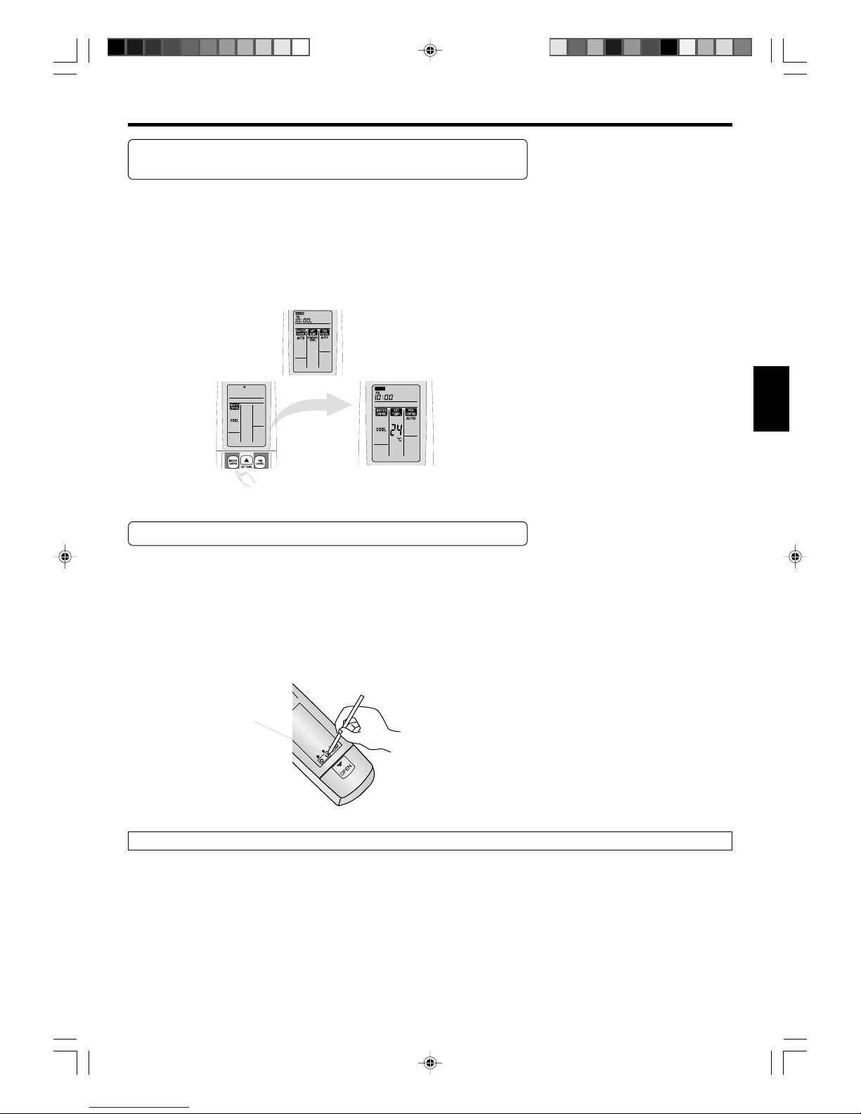
About the Remote Control Unit operation and display
(dedicated display function)
● When a button is pressed on the Remote Control Unit, only indicators related to
that operation appear on the Remote Control Unit display while unrelated indicators disappear (dedicated display function). This function allows easy confirmation of operation contents and is very convenient.
● To change the operation mode, temperature, or airflow, press the related button
for the dedicated display function. Press the related button again to change the
settings and transmit the signal to the Indoor Unit.
(Ex.) The MASTER CONTROL button is pressed during the auto mode.
* Press the button twice to change to the cooling mode
After approximately 3 seconds, all items
on the display
appear.
About the TEST RUN button
● This button is used when installing the air conditioner and should not be used
under normal conditions, as it will cause the air conditioner’s thermostat function to operate incorrectly.
● If this button is press during normal operation, the unit will switch to the test
operation mode and the OPERATION Indicator Lamp and TIMER Indicator Lamp
on the Indoor Unit will flash simultaneously.
● To the stop the test operation mode, press the START/STOP button to stop the air
conditioner.
About the Compulsory Cooling Mode
● If the TEST RUN button is pressed during the cooling mode, the unit will change to the compulsory cooling mode and the
room will be cooled regardless of the thermostat setting.
● Use the compulsory cooling mode to collect refrigerant in the outdoor unit before moving the air conditioner. (Do not use
this button under normal conditions.)
TEST RUN button
(Remote Control Unit
backside)
PREPARATION
9312556014-En.pm6.5 2003.6.11, 5:08 PM4
Page 8
En-5
Turn on the Power
Connect the Power Supply Plug (Fig. 1 J) to an electrical outlet;
in the case of a direct line connection, turn on the circuit breaker.
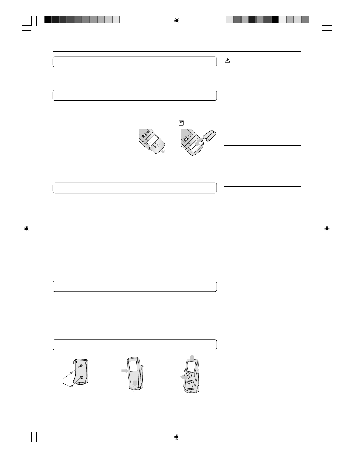
Load Batteries (LR03
××
××
× 2)
1
Press and slide the battery compartment lid on the reverse side to open it.
Slide in the direction of the arrow while pressing the mark.
2
Insert batteries.
Be sure to align the battery polarities (+/-) correctly.
3
Close the battery compartment lid.
Set the Current Time
1
Press the SET (TIMER) button (Fig. 5 j)
Use the tip of a ball-point pen or other small object to press the button.
2
Use the +/- SET TIME buttons (Fig. 5 i)to adjust
the clock to the current time.
+ button: Press to advance the time.
- button: Press to reverse the time.
(Each time the buttons are pressed,the time will be advanced/reversed in
one-minute steps.hold the buttons depressed to change the time quickly
in ten-minute steps.)
3
Press the SET (TIMER) button.
This completes the time setting and starts the clock.
To Use the Remote Control Unit
● The Remote Control Unit must be pointed at signal receiver (Fig. 2 4) to operate
correctly.
● Operating Range: About 7 meters.
● When a signal is properly received by the air conditioner, a beeping sound will
be heard.
● If no beep is heard, press the Remote Control Unit button again.
Remote Control Unit Holder
CAUTION!
● Take care to prevent infants from
accidentally swallowing batteries.
● When not using the Remote Control Unit
for an extended period, remove the
batteries to avoid possible leakage and
damage to the unit.
● If leaking battery fluid comes in contact
with your skin, eyes, or mouth, immediately wash with copious amounts of
water, and consult your physician.
● Dead batteries should be removed
quickly and disposed of properly, either
by placing in a public battery collection
receptacle, or by returning to appropriate
authority.
● Do not attempt to recharge dry batteries.
Never mix new and used batteries, or
batteries of different types.
Batteries should last about one year
under normal use. If the Remote Control Unit’s operating range becomes appreciably reduced, replace the batteries
and press the ACL button with the tip of
a ballpoint pen or other small object.
1Mount the Holder. 2Set the Romote Control
Unit.
3To remove the Remote Con-
trol Unit (when use hand).
Screws
Insert
Press in
Slide up
Pull out
9312556014-En.pm6.5 2003.6.11, 5:08 PM5
Page 9
En-6
OPERATION
sss
tt
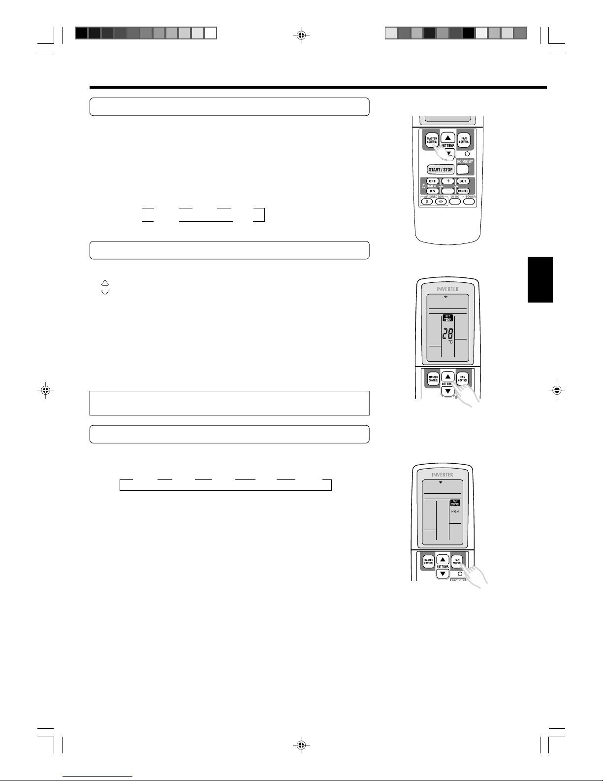
To Select Mode Operation
1
Press the START/STOP button (Fig. 5 `).
The Indoor Unit’s OPERATION Indicator Lamp (red) (Fig. 2 5) will light.
The air conditioner will start operating.
2
Press the MASTER CONTROL button (Fig. 6 d) to select the desired mode.
Each time the button is pressed, the mode will change in the following
order.
AUTO HEAT COOL
DRY FAN
About three seconds later, the entire display will reappear.
To Set the Thermostat
Press the SET TEMP. button (Fig. 5 \).
: Press to raise the thermostat setting.
: Press to lower the thermostat setting.
●Thermostat setting range:
AUTO .................................. 18-30 °C
Heating ............................... 16-30 °C
Cooling/Dry ........................ 18-30 °C
The thermostat cannot be used to set room temperature during the FAN mode (the
temperature will not appear on the Remote Control Unit’s Display).
About three seconds later, the entire display will reappear.
The thermostat setting should be considered a standard value, and may differ
somewhat from the actual room temperature.
To Set the Fan Speed
Press the FAN CONTROL button (Fig. 5 e).
Each time the button is pressed, the fan speed changes in the following order:
AUTO HIGH MED LOW QUIET
About three seconds later, the entire display will reappear.
When set to AUTO:
Heating : Fan operates so as to optimally circulate warmed air.
However, the fan will operate at very low speed when the temperature of the air issued from the indoor unit is low.
Cooling : As the room temperature approaches that of the thermostat setting,
the fan speed becomes slower.
Fan : Internal UV cleaning operates using low airflow.
The fan will operate at a very low setting during Monitor operation
and at the start of the Heating mode.
When set to QUIET:
SUPER QUIET operation begins. The Indoor Unit’s airflow will be reduced for quieter operation.
● SUPER QUIET operation cannot be used during Dry mode. (The same is true
when dry mode is selected during AUTO mode operation.)
● During Super Quiet operation, Heating and Cooling performance will be reduced
somewhat.
ssss
s
9312556014-En.pm6.5 2003.6.11, 5:08 PM6
Page 10
En-7
To Stop Operation
Press the START/STOP button.
The OPERATION Indicator Lamp (red) (Fig. 2 5) will go out.
About AUTO CHANGEOVER Operation
AUTO: ● When AUTO CHANGEOVER operation first selected, the fan will oper-
ate at very low speed for about one minute, during which time the unit
detects the room conditions and selects the proper operating mode.
If the differance between thermostat setting and actual room temperature is more than +2 °C → Cooling or dry operation
If the difference between thermostat setting and actual room temperature is within ±2 °C → Monitor operation
If the difference between thermostat setting and actual room temperature is more than –2 °C → Heating operation
● When the air conditioner has adjusted your room’s temperature to near
the thermostat setting, it will begin monitor operation. In the monitor
operation mode, the fan will operate at low speed. If the room temperature subsequently changes, the air conditioner will once again
select the appropriate operation (Heating, Cooling) to adjust the temperature to the value set in the thermostat.
(The monitor operation range is ±2 °C relative to the thermostat setting.)
● If the mode automatically selected by the unit is not what you wish,
select one of the mode operation (HEAT, COOL, DRY, FAN).
About Mode Operation
Heating: ● Use to warm your room.
● When Heating mode is selected, the air conditioner will operate at very
low fan speed for about 3 to 5 minutes, after which it will switch to the
selected fan setting. This period of time is provided to allow the indoor
unit to warm up before begin full operation.
● When the room temperature is very low, frost may form on the outside
unit, and its performance may be reduced. In order to remove such
frost, the unit will automatically enter the defrost cycle from time to
time. During Automatic Defrosting operation, the OPERATION Indicator Lamp (red) will flash, and the heat operation will be interrupted.
Cooling: ● Use to cool your room.
Dry: ● Use for gently cooling while dehumidifying your room.
● You cannot heat the room during Dry mode.
● During Dry mode, the unit will operate at low speed; in order to adjust
room humidity, the Indoor Unit’s fan may stop from time to time. Also,
the fan may operate at very low speed when adjusting room humidity.
● The fan speed cannot be changed manually when Dry mode has been
selected.
Fan: ● Use to circulate the air throughout your room.
During Heating mode:
Set the thermostat to a temperature setting that is higher than the current room
temperature. The Heating mode will not
operate if the thermostat is set lower than
the actual room temperature.
During Cooling/Dry mode:
Set the thermostat to a temperature setting that is lower than the current room
temperature. The Cooling and Dry modes
will not operate if the thermostat is set
higher than the actual room temperature
(in Cooling mode, the fan alone will operate).
During Fan mode:
You can not use the unit to heat and cool
your room.
9312556014-En.pm6.5 2003.6.11, 5:08 PM7
Page 11

En-8
TIMER OPERATION
To Cancel the Timer
Press the CANCEL button.
To Change the Timer Settings
Perform operations 2–4.
To Stop Air Conditioner Operation
while the Timer is Operating
Press the START/STOP button.
To Use the OFF TIMER or ON TIMER
Open the Remote Control Unit lid to perform the timer function settings.
1
Press the START/STOP button (Fig. 5 `)
(if the unit is already operating, proceed to step 2).
The Indoor Unit’s OPERATION Indicator Lamp (red) (Fig. 2 5) will light.
2
Select the desired timer operation time, and then press
the OFF TIMER button or the ON TIMER button.
The OFF or ON timer indicator flashes.
3
Use the SET TIME buttons (Fig. 5 i) to adjust the desired OFF time or ON time.
+ Button: Press to advance the time.The time advances in 5-minutes in-
crements.
- Button: Press to reverse the time.The time goes backward in 5-minute
increments.
4
Point the Remote Control Unit towards the Indoor Unit
and press the SET button.
The OFF or ON timer Indicator stops flashing.
The TIMER Indicator Lamp (green) on the Indoor Unit will light.
If the ON TIMER function is selected, the air conditioner operation stops.
To Use the Program timer
1
Press the START/STOP button (Fig. 5 `)
(if the unit is already operating, proceed to step 2).
The Indoor Unit’s OPERATION Indicator Lamp (red) (Fig. 2 5) will light.
2
Set the desired times for OFF timer and ON timer.
See the section “To Use the OFF timer or ON timer” to set the desired
mode and times.
The indoor unit’s TIMER Indicator Lamp (green) (Fig.2 6) will light.
About the Program timer
● The PROGRAM timer allows you to integrate OFF timer and ON timer operations
in a single sequence. The sequence can involve one transition from OFF timer to
ON timer,or from ON timer to OFF timer,within a twenty-four hour period.
● The first timer function to operate will be the one set nearest to the current
time.The order of operation is indicated by the arrow in the Remote Control
Unit’s display (OFF → ON,or OFF ← ON).
● One example of PROGRAM timer use might be to have the air conditioner automatically stop (OFF timer)after you go to sleep,then start (ON timer)automatically
in the morning before you arise.
Before using the timer function,be sure that the Remote Control Unit is set to the correct current time (See page 5).
To Cancel the Timer
Press the CANCEL button.
TIMER Indicator Lamp(green) will go out.
Canceling the OFF TIMER or the ON TIMER
1. Press the TIMER button of the function to
cancel (OFF or ON).
2. Press the CANCEL button.
To Change the Timer Settings
1. Press the TIMER button of the function
to change (OFF or ON).
2. Set the timer using the “+” and “-”
TIMER buttons.
3. Press the SET button.
To Stop Air Conditioner Operation
while the Timer is Operating
Press the START/STOP button.
9312556014-En.pm6.5 2003.6.11, 5:08 PM8
Page 12

En-9
SLEEP TIMER OPERATION
→ 1.0 → 2.0 → 3.0 → 5.0 → 7.0 → 9.0(hour)
(RESET)
→ 1.0 → 2.0 → 3.0 → 5.0 → 7.0 → 9.0(hour)
(RESET)
To Cancel the Timer:
Press the CANCEL (TIMER) button.
To Stop the Air Conditioner During
Timer Operation:
Press the START/STOP button.
To Use the SLEEP timer
While the air conditioner is operating or stopped, press the
SLEEP button (Fig. 5 ]).
Each time the button is presssd, the time changes in the following order:
The Indoor Unit’s OPERATION Indicator Lamp (red) (Fig. 2 5) and the TIMER Indicator Lamp (green) (Fig. 2 6) light.
To Change the Timer Settings
Press the SLEEP button once to display the last setting time.
Press the SLEEP button again to change the time.
Each time the button is pressed, the time changes in the following order (Change
from the last setting time):
Unlike other timer functions, the SLEEP timer is used to set the length of time until air conditioner operate is stopped.
Confirmation of TIMER's time
The left time of the TIMER which is being set currently will be displayed for 5 seconds.
9312556014-En.pm6.5 2003.6.11, 5:08 PM9
Page 13

En-10
ADJUSTING THE DIRECTION OF AIR CIRCULATION
● Adjust the up, down, left, and right AIR directions with the AIR DIRECTION buttons on the Remote Control Unit.
● Use the AIR DIRECTION buttons after the Indoor Unit has started operating and the airflow-direction louvers have
stopped moving.
* The Remote Control Unit
display does not change.
Vertical Air Direction Adjustment
Open the lid on the Remote Control Unit.
Push the up/down AIR DIRECTION button.
● When the up/down AIR
DIRECTION button is
pushed, the airflow
direction changes within
the range to the right.
●
You can select the desired
airflow direction.
R
DANGER!
● When adjusting the Right-Left Louvers, it
is necessary to stop the Air-Conditioner
first and make sure that it stops completely
before adjusting the direction.
1
5
6
7
8
2
3
4
Cooling/Dry range1234 Heating range5678
Right-Left Adjustment
Open the lid on the remote control unit.
Push the left/right AIR DIRECTION button.
● When the left/right AIR DIRECTION button is pushed, the airflow direction will
change in the following order.
● You can select the desired airflow direction.
● The Indoor Unit is set for front airflow when the
unit is turned on.
R
DANGER!
● Never place fingers or foreign objects inside the outlet ports, since the internal fan
operates at high speed and could cause
personal injury.
About airflow direction adjustments
●
When the unit is turned on or the op-
eration mode is changed, the position
of the airflow-direction louvers is automatically set as listed below to match
the operation mode (heating, cooling,
etc.) selected.
Cooling/Dry/Fan: horizontal airflow
Heating: downward airflow
● During HI-POWER operation (see page
12), the up/down airflow direction is set
automatically to optimize the heating
and cooling performance.
● When the AIR DIRECTION buttons on
the Remote Control Unit are pressed,
it may take a short time for the up/
down airflow-direction louvers or the
left/right airflow-direction louvers to
reach the desired position.
During that time, the airflow direction
cannot be adjusted even if the AIR DIRECTION buttons are repeatedly
pressed.
● During the monitor period in the auto
mode (see page 7), horizontal airflow
direction is set and cannot be adjusted.
● If the up/down AIR DIRECTION button
is pressed during the up/down swing
operation (see page 11), the up/down
swing operation will stop. In addition,
if the left/right AIR DIRECTION button
is pressed during the left/right swing
operation, the left/right swing operation will stop.
* The up/down airflow-direction louvers move in the
direction of the arrow from the closed position.
●
In order to maximize the heating and cooling
performance, use the ranges above.
Fan range 12345678
* The Remote Control Unit
display does not change.
ss
t
t
Front airflow
Right airflow
Front airflow
Left airflow
9312556014-En.pm6.5 2003.6.11, 5:08 PM10
Page 14

En-11
SWING OPERATION
Begin air conditioner operation before performing this procedure.
To select SWING Operation
Open the Remote Control Unit lid to perform swing operation
settings.
Press the SWING button (Fig. 5 m).
The SWING Display (Fig. 6 T) will light.
Each time the SWING button is pressed, the swing operation will change in the
following order.
To stop SWING Operation
Press the SWING button and select STOP.
Airflow direction will return to the setting before swing was begun.
Up/down swing operation Left/right swing operation
Swing operation stops Up/down/left/right swing operation
About Swing Operation
● Up/down swing: Swing operation begins using the
following range according to the current airflow direction.
Airflow direction is 1–4 (for cooling, dry).
With the upper airflow-direction louver in the
horizontal position, the lower airflow-direction
louver moves (swings) to direct airflow to a wide
area.
Airflow direction is 5–8 (for heating).
With the airflow-direction louvers set for downward or straight down airflow, airflow is directly
mainly at the floor.
● Left/right swing: The airflow-direction louvers move
(swing) in the left/right airflow direction.
● Up/down/left/right swing: The airflow-direction louvers
move (swing) in both the up/down and left/right airflow
directions.
●
The SWING operation may stop temporarily when the
air conditioner’s fan is not operating, or when operating
at very low speeds.
●
If the up/down AIR DIRECTION button is pressed during
the up/down swing operation, the up/down swing
operation will stop and if the left/right AIR DIRECTION
button is pressed during the left/right swing operation,
the left/right swing operation will stop.
9312556014-En.pm6.5 2003.6.11, 5:08 PM11
Page 15

En-12
HI-POWER OPERATION
Begin air conditioner operation before performing this procedure.
To select HI-POWER Operation
1
Start air conditioner operation in auto, heating, cooling, or fan mode.The OPERATION Indicator Lamp (red)
on the Indoor Unit (Fig. 2 5) will light.
2
Open the Remote Control Unit lid, and then press the
HI-POWER button.The HI-POWER OPERATION Indicator Lamp (orange) on the Indoor Unit (Fig. 2 9) will
light.
About HI-POWER Operation
● During heating mode
The Indoor Unit will operate at maximum power until the room temperature is 2°C above the thermostat setting.
● During cooling mode
The Indoor Unit will operate at maximum power until the room temperature is 1°C below the thermostat setting.
● During fan mode
The airflow from the Indoor Unit is increased.
● During dry mode
The airflow cannot be set during HI-POWER operation.
ECONOMY OPERATION
About ECONOMY Operation
At the maximum output, ECONOMY Operation is approximately 70% of normal air conditioner operation for heating and
cooling.
When ECONOMY operation is performed during the cooling mode, dehumidification is improved. This function is especially
convenient when you want to remove the humidity in the room without significantly lowering the room temperature.
During ECONOMY operation, the thermostat setting automatically changes according to the outdoor temperature to avoid
unnecessary heating and cooling for the most economical operation.
●
If the room is not heated (or cooled) well during economy operation, select normal operation.
●
Once air conditioner operation is stopped, normal operation begins when the indoor unit is turned on again.
●
During the monitor period in the auto mode, the air conditioner operation will not change to ECONOMY operation even if
ECONOMY operation is selected by pressing the ECONOMY operation button.
To stop HI-POWER Operation
Press the HI-POWER button again.
The HI-POWER OPERATION Indicator Lamp (orange) on the Indoor Unit will go
out.
Normal operation begins.
However, HI-POWER Operation will automatically stop under the following conditions.
During Air Conditioner Operation
Open the remote control unit lid, and then press the
ECONOMY operation button.
“ECO” appears on the Remote Control Unit display.
●
Economy operation begins.
Press the ECONOMY Operation button again
“ECO” disappears from the Remote Control Unit display.
●
Normal operation begins.
9312556014-En.pm6.5 2003.6.11, 5:08 PM12
Page 16

En-13
● During heating mode
The room temperature is 2°C above the thermostat setting.
● During cooling mode
The room temperature is 1°C below the thermostat setting or 30 minutes has
passed since the HI-POWER operation began.
● During fan mode
15 minutes has passed since the HI-POWER operation began.
UV AIR CLEANING/ANION OPERATION
● The room air is disinfected with UV (ultraviolet rays).
● During UV air cleaning, anions, which are gentle on the body, spread throughout
the room.
The settings can be changed after pressing the AIR CLEAN button on the Remote
Control Unit two times.
To perform UV Air Cleaning during Air Conditioner Operation
Press the AIR CLEAN button during air conditioner operation.
The UV AIR CLEAN/ANION Indicator Lamp (blue) on the Indoor Unit will light.
To stop UV Air Cleaning only
Select STOP using the AIR CLEAN button.
The UV AIR CLEAN/ANION Indicator Lamp (blue) on the Indoor Unit will go out.
AIR CLEAN disappears from the Remote Control Unit display.
UV air cleaning stops but air conditioner operation continues.
To perform UV Air Cleaning only
Press the AIR CLEAN button while air conditioner operation is
stopped.
The OPERATION Indicator Lamp (red) and the UV AIR CLEAN/ANION Indicator Lamp
(blue) on the Indoor Unit will light.
UV air cleaning will begin. Press the START/STOP button to stop the UV air cleaning.
To stop All Operation
Press the START/STOP button.
About UV Air Cleaning
● During UV air cleaning, a small amount of ozone and odor may be produced.
● UV air cleaning cannot be used to remove carbon monoxide gas or alcohol fumes. Ventilate the room occasionally during
UV air cleaning to avoid a lack of oxygen and possible suffocation.
● The airflow can be changed using the FAN CONTROL button.
UV air cleaning is most effective with the airflow at the maximum output.
About the Anion Generator
● The anion generator operates continuously during the UV air cleaning and produces anions.
● When the anion generator becomes dirty, a buzzing sound may be produced. If this occurs, perform anion generator
maintenance.
9312556014-En.pm6.5 2003.6.11, 5:08 PM13
Page 17

En-14
COIL DRY OPERATION
● When the COIL DRY button on the Remote Control Unit is pressed, the inside of the Indoor Unit is dried, and then the UV
(ultraviolet rays) lamp produces small amounts of ozone to suppress the growth of mold and various germs.
● After the COIL DRY button is pressed, COIL DRY operation is performed for approximately 30 minutes and then automatically stops.
To start COIL DRY Operation
Press the COIL DRY button (when the air conditioner is operating or stopped).
Only the OPERATION Indicator Lamp (red) on the Indoor Unit will light.
“COIL DRY” appears on the Remote Control Unit display and disappears after approximately 30 minutes.
If the COIL DRY button is pressed again during COIL DRY operation, COIL DRY operation will start again.
To stop COIL DRY Operation
Press the START/STOP button during COIL DRY operation.
The OPERATION Indicator Lamp (red) on the Indoor Unit will go out.
● The Remote Control Unit will be in the operation-stopped condition.
NOTE!
● When COIL DRY operation begins, the
Indoor Unit operates in the heating
mode and the fan mode to dry the inside
of the Indoor Unit. As a result, the room
temperature and humidity may rise
slightly.
● During COIL DRY operation, a small
amount of ozone and odor may be
produced.
● COIL DRY operation cannot be used to
clean the air in the room.
● COIL DRY operation is most effective
when performed frequently.
About COIL DRY Operation
The following procedures are performed during COIL DRY operation before the
operation automatically stops after approximately 30 minutes.
● Drying (approximately 15 minutes)
After COIL DRY operation starts, the inside of the Indoor Unit is dried.
● Ozone (approximately 15 minutes)
The UV (ultraviolet rays) lamp produces small amounts of ozone to suppress the
growth of mold and various germs.
● COIL DRY operation stops
9312556014-En.pm6.5 2003.6.11, 5:08 PM14
Page 18

En-15
MANUAL AUTO OPERATION
Use the MANUAL AUTO operation in the event the Remote Control Unit is lost or otherwise unavailable.
REMOTE CONTROL UNIT UNAVAILABLE (MANUAL AUTO OPERATION)
If the Remote Control Unit is lost or the batteries are dead, the air conditioner can be operated provisionally from the indoor
unit.
3. Close the front panel.
● Do not operate the air contidioner with the front panel
open.
1. Open the front panel.
Grab both sides of the front panel and open the front
panel until it is held in place. (The panel will remain open
even after it is released.)
2. Press the MAINTENANCE/MANUAL AUTO
button for 3 seconds.
● Press the MAINTENANCE/MANUAL AUTO button and
continue to press the button even after a beeping sound
is produced.
The OPERATION Indicator Lamp (red) on the Indoor Unit
will light.
The air conditioner will operate in the auto mode (see
page 17). Airflow will be automatic, airflow direction will
be the standard setting, and the thermostat settings will
be the standard temperature.
Stopping MANUAL AUTO Operation
Press the MAINTENANCE/MANUAL AUTO button for 3 seconds.
Air conditioner operation will stop and the OPERATION Indicator Lamp (red) on the Indoor Unit will go out.
9312556014-En.pm6.5 2003.6.11, 5:08 PM15
Page 19

En-16
TEMPERATURE MONITORING
● The room temperature and the outdoor temperature can be displayed. This information is helpful in selecting the appro-
priate operation mode and thermostat setting.
● Use this function after the air conditioner is operating.
To change the Temperature Monitoring
Room temperature display
Room
temperature
Outdoor
temperature
The OUTDOOR TEMP./ROOM
TEMP. Indicator Lamp (green)
on the Indoor Unit will light.
The OUTDOOR TEMP./ROOM
TEMP. Indicator Lamp (green)
on the Indoor Unit will light.
No display
Outdoor
temperature display
● Each time the MONITOR button is pressed, the display on the Indoor
Unit changes in the following order.
● When the power supply cord is plugged into the electrical outlet and the air
conditioner operates for the first time, the room temperature is displayed.
Use the MONITOR button to display the room temperature or outdoor temperature.
● If the outdoor temperature is selected, the room temperature will be displayed after 10 seconds. (The OUTDOOR TEMP./ROOM TEMP. Indicator Lamp
goes out.)
● To turn the temperature monitor display off, press the MONITOR button
until there is no temperature displayed. For UV air cleaning (see page 13),
the UV AIR CLEAN/ANION Indicator Lamp (blue) on the Indoor Unit will go
out. This is useful at times when the display is too bright such as at bedtime.
About the Temperature Monitor
● The temperature displayed is the temperature of the Indoor Unit and Outdoor Unit intake air. Depending on the
installation conditions of the Indoor Unit and Outdoor
Unit, the actual temperature may be different. Use only
as a reference.
● Approximately 1 minute after the start of heating or cooling, the temperature displayed will be higher than the
thermostat setting on the remote control for heating and
will be lower than the thermostat setting for cooling in
order for the hi-power operation to start (see page 26).
● During air conditioner operation, the outdoor temperature displayed is affected by the exhaust and heat transfer from the outdoor unit. The displayed temperature will
be higher than the actual temperature during cooling and
drying and will be lower than the actual temperature during heating. (The difference between the actual and displayed temperature will be larger if the outdoor unit is
installed in a narrow space.)
● Approximately 1 minute after air conditioner operation
begins, the temperature is being detected and will not be
displayed. During this time “- -” is displayed.
● The displayed temperature range is -9°C–45°C. If the tem-
perature is below -9°C, “-9” will be displayed and if the
temperature exceeds 45°C, “45” will be displayed.
● If the ON TIMER is set (see page 8) and the air conditioner is stopped, the temperature will not displayed on
the Indoor Unit even if the MONITOR button is pushed.
(The signal cannot be received.)
● Immediately after the automatic defrosting operation (see
page 26), the air temperature around the Indoor Unit will
be low and unstable and may cause the displayed room
temperature to change.
During air conditioner operation,
press the MONITOR button.
* The Remote Control Unit display
does not change.
9312556014-En.pm6.5 2003.6.11, 5:08 PM16
Page 20

En-17
AUTOMATIC FILTER CLEANING FUNCTION
● This is a convenient function that automatically removes dust from the air filters after a set amount of time of air conditioner
operation.
● The automatic filter cleaning function can also be started using the remote control unit.
CAUTION!
Do not touch the air filters during the
automatic filter cleaning.
● The Indoor Unit may malfunction if the
air filters are pulled or pushed.
● If the air filters are unnecessarily pulled,
they may be damaged or fall and cause
personal injury.
About the Automatic Filter Cleaning function
● Depending on how dirty the air filters are, all of the dust may not be removed
from the air filters during the automatic filter cleaning. In this case, perform
automatic filter cleaning again.
● If dust remains on the air filters after automatic filter cleaning has been performed a number of times, perform dust box maintenance (see page 19).
● Depending on the condition of the dust on the air filters, such as if the dust is
particularly oily or hardened, the dust may not be removed during the automatic filter cleaning. In this case, remove the air filters and clean with water
(see page 22).
● During automatic filter cleaning, clicking or hissing sounds may be produced.
Automatic Filter Cleaning
About operating the Automatic Filter Cleaning
● Automatic filter cleaning is performed after the air conditioner operates for a
set amount of time and is stopped or the FILTER MAINTENANCE button on the
Remote Control Unit is pressed.
● During automatic filter cleaning, the MAINTENANCE Indicator Lamp (green) on
the Indoor Unit will light.
1. Air filters come out
● The air filters automatically come out of the indoor unit under the front panel. At
this time, the dust on the air filters is collected in the dust boxes (behind the front
panel).
Front panel
2. Air filters retract
● After the air filters come out, they automatically retract to their original positions
in the Indoor Unit.
● When the automatic filter cleaning is complete, the MAINTENANCE Indicator
Lamp (green) on the Indoor Unit goes out.
Changing the FILTER MAINTENANCE Interval Switch
● Use the FILTER MAINTENANCE Interval Switch on the back of the Remote
Control Unit to select the amount of time of air conditioner operation (150
hours or 200 hours) after which automatic filter cleaning will be performed.
200 hours of operation
The air filters will be automatically cleaned after approximately 200 hours of air
conditioner operation. This is the standard setting.
150 hours of operation
The air filters will be automatically cleaned after approximately 150 hours of air
conditioner operation. Select this setting to clean the air filters more frequently.
9312556014-En.pm6.5 2003.6.11, 5:08 PM17
Page 21

En-18
Automatic Filter Cleaning using the Remote Control Unit
Press the FILTER MAINTENANCE button
(when the air conditioner is operating or stopped).
*The Remote Control Unit display does not change.
About the MAINTENANCE Indicator Lamp
MAINTENANCE Indicator Lamp (green) lights
The MAINTENANCE Indicator Lamp (green) will light during automatic filter cleaning.
MAINTENANCE Indicator Lamp (green) flashes (about once
every 2 seconds)
The MAINTENANCE Indicator Lamp will flash during automatic filter cleaning if the air filters are not installed or are
pulled. If this occurs during air conditioner operation, unplug the power supply cord from the electrical outlet and
follow procedures 1 and 4 in Dust Box Maintenance (see
pages 19 and 21) to install the air filters.
MAINTENANCE Indicator Lamp (red) lights
The MAINTENANCE Indicator Lamp (red) will light if it is
time to clean the dust boxes. If this occurs, clean the dust
boxes (see page 19).
● The MAINTENANCE Indicator Lamp
(green) on the Indoor Unit will light.
● Automatic filter cleaning begins.
● If the FILTER MAINTENANCE button
is pressed during air conditioner operation, the air conditioner will stop,
automatic filter cleaning will be performed, and the air conditioner will
start operating again after the automatic filter cleaning is complete.
● Even if the FILTER MAINTENANCE
button is pressed during the automatic filter cleaning, the cleaning will
not stop.
About the notification for Dust box cleaning
● The MAINTENANCE Indicator Lamp (red) on the Indoor
Unit lights to notify that the dust boxes should be cleaned.
If the lamp is lit, clean the dust boxes (see page 19).
● The MAINTENANCE Indicator Lamp (red) will light after
approximately 2,000 hours of air conditioner operation.
● While the MAINTENANCE Indicator Lamp (red) is lit, automatic filter cleaning will not be performed even if the
FILTER MAINTENANCE button on the remote control unit
is pressed. Clean the dust boxes, and then press the MAINTENANCE/MANUAL AUTO button (see page 21). (The
MAINTENANCE indicator lamp (red) will go out.)
● The MAINTENANCE Indicator Lamp (red) will light if the
air conditioner is operating or stopped.
● If the dust boxes are not cleaned and the MAINTENANCE
Indicator Lamp (red) goes out, dust may fall from the indoor unit the next time automatic filter cleaning is performed. If the MAINTENANCE Indicator Lamp (red) is lit,
be sure to clean the dust boxes.
● If the air filters are pulled or pushed during the automatic filter cleaning, the air
filters will stop moving and the MAINTENANCE Indicator Lamp (green) will
flash. If this occurs, follow procedures 1 and 4 in Dust box MAINTENANCE (see
pages 19 and 21) to install the air filters.
● If the air filters are hanging out of the Indoor Unit after installation, they may
automatically retract into the Indoor Unit.
● If furniture or obstacles are place directly below the Indoor Unit, automatic
filter cleaning will not operate correctly if the air filters come out of the Indoor
Unit and hit them.
9312556014-En.pm6.5 2003.6.11, 5:08 PM18
Page 22

En-19
PERFORMING MAINTENANCE
● Frequent maintenance will extend the life of the air conditioner and improve the cooling and heating performance.
● Before maintenance, stop air conditioner operation using the remote control and unplug the power supply cord from the
electrical outlet.
CAUTION!
Before cleaning the air conditioner, be sure to
turn it off and unplug the power supply cord
from the electrical outlet.
The internal fan operates at high speed and
could cause personal injury.
When removing the dust boxes, do not touch
any metal parts (heat exchanger, etc.).
Personal injury may result.
When cleaning the air conditioner, do not
stand on any unstable objects.
You might fall and personal injury could
result.
When cleaning the dust boxes, be sure to
install them securely.
If the dust boxes are not properly installed,
they could fall and cause personal injury.
Dust Box Maintenance
● If the MAINTENANCE Indicator Lamp (red) on the Indoor Unit is lit, be sure to clean the dust boxes. If the Indoor Unit is
installed in an area with a lot of dust, clean the dust boxes every 3 months even if the MAINTENANCE Indicator Lamp (red)
is not lit.
● When cleaning the dust boxes, dust may fall to the floor. Lay newspaper, etc. under the Indoor Unit before cleaning the dust
boxes.
1. Remove the dust boxes and air filters from the indoor unit. Remove the air filters
from the dust boxes.
Preparation ● Stop the air conditioner using the Remote Control Unit.
● Unplug the power supply cord from the electrical outlet.
1. Open the front panel.
Front panel
Grab both sides of the front panel and fully open the
front panel. Continue to open the front panel past the
horizontal position. (The panel will remain open even
after it is released.)
2. Open the latches on the dust boxes.
Dust boxes
“Click”
“Click”
Latches
Open the two latches (yellow) on the ends of each dust
box.
3. Remove the dust boxes and air filters.
Grab the center of each dust box, lift the bottom in direction 1, and then remove the dust box in direction 2.
(Remove the dust boxes and air filters together.)
4. Remove the air filter from each dust box.
Grab the holding position on the air filter and pull the air
filter out from the dust box in the direction of the arrow.
Holding
position
Dust box
Air filter
● When the air filter is removed from the dust box, dust
may fall from the dust box. Lay newspaper, etc. under
the dust box before removing the air filter.
9312556014-En.pm6.5 2003.6.11, 5:08 PM19
Page 23

En-20
2. Remove the dust collected in the dust boxes and clean the dust boxes.
1. Open the dust boxes.
● When opening each dust box, make sure the front case
is facing down and the rear case is facing up. If the
front case is facing up, a lot of dust will fall out of the
dust box when it is opened.
1 Make sure the rear case is on top and the press the
tab on the end of the case in the direction of the arrow
(stamped on the case).
Latch
Front case
(Light blue)
Rear case
(Dark blue)
2 While pressing the tab, lift up the side of the rear case
with the tab. Remove the projection on the other side
of the rear case from the hole in the front case and
open the dust box.
Ta b
Rear case
Projection
Front case
<Front case>
<Rear case>
2. Open the brush holder on the front case
and dispose of the dust.
< Front case (light blue)>
Open the brush holder and dispose of the collected dust.
Brush holder
<Rear case (dark blue)>
Grab the tab on each brush holder on the rear case, open
the brush holders, and then dispose of the collected dust.
Tabs
● Do not forcefully open the brush holders. The brush
holders may be damaged and the Indoor Unit may
malfunction.
3. Clean the inside of the front and rear cases.
Close the brush holders on the front and rear cases and
remove the dust on the brushes with a vacuum cleaner
or a toothbrush, etc.
< Front case >
Brushes
<Rear case >
Brushes
4. Wash the front and rear cases with water
if they are extremely dirty.
1 Lightly rub the brushes clean with 40°C–45°C hot wa-
ter. If the brushes are difficult to clean, apply a mild
synthetic laundry detergent (low or neutral alkalinity)
and rub lightly.
2 Rub the front and rear cases lightly with a sponge.
3 Rinse under running water.
4 Remove the water from the front and rear cases.
5 Wipe the brushes and cases with a towel, etc., and
place in a shaded area to dry.
● Do not use a cleaner other than a mild synthetic laundry
detergent (low or neutral alkalinity).
● Do not clean with hot water above 60°C.
● Do not clean with any abrasive or hard object.
● Do not dry with hot air from a hair dryer, etc.The cases
may be deformed and the brushes may come off.
● After washing with water, make sure the dust boxes are
completely dry before installation. The brushes are especially difficult to dry so wipe them with a towel, etc. to
make sure they are completely dry. If the dust boxes are
installed wet, the dust may not be removed from the air
filters during automatic filter cleaning.
9312556014-En.pm6.5 2003.6.11, 5:08 PM20
Page 24

En-21
3. Assemble the dust boxes, and install the air filters.
1. Assemble each dust box.
1 Place the front casing facing down and insert the pro-
jection on the rear case into the hole in the front case.
Rear case
(dark blue)
Projection
Front case
(light blue)
● When putting the front and rear cases together, make
sure that the brush holders are not sticking out.
2 WMake sure the side of the rear case with the tab over-
laps the front case and then install the rear case.
Latch
“Click”
Rear case
Front case
2. Install the air filters in the dust boxes.
1 Align the insertion directions written on each dust box
and air filter, and then insert the air filter into the dust
box between the front and rear cases.
Air filter
Dust box
Dust box
Air filter
● When inserting the air filter, make sure it is not upside
down or backwards, and then install correctly. If the air
filter is not installed correctly, the indoor unit may
malfunction.
● The air filter will be difficult to insert if you are pressing
down on the dust box.
2 Insert the air filter until it stops.
4. Install the dust boxes and air filters in the Indoor Unit, and then press the MAINTENANCE/
MANUAL AUTO button.
1. Install the dust boxes and air filters in the
indoor unit.
● When installing the dust boxes, make sure that the two
latches (yellow) on the ends of each dust box are open. If
the dust boxes are installed with the latches closed, the
indoor unit may malfunction.
1 Open the front panel, grab the holding position on
each air filter, and then insert each filter into the indoor unit until it stops.
Open the
latches.
Open the
latches.
2 Install the dust boxes and close the two latches (yel-
low) on the ends of each dust box.
Latch
“Click”
● If the air filters are hanging out of the indoor unit when
the dust boxes and air filters are filters are installed, remove the dust boxes and air filters and install them again.
2. Plug the power supply cord into the electrical outlet and press the MAINTENANCE/
MANUAL AUTO button.
After installing the dust boxes, plug the power supply
cord into the electrical outlet, and then press the MAINTENANCE/MANUAL AUTO button on the Indoor Unit for
about 1 second.
MAINTENAN
CE/MANUAL
AUTO button
(Press for 1
second.)
MANUAL AUTO
operation
(Press for 3 seconds.)
“Beep”
* The MAINTENANCE Indicator Lamp (red)
will go out,if it is lit at this time.
● Press the MAINTENANCE/MANUAL AUTO button and
release it after a beeping sound is produced. If the
MAINTENANCE/MANUAL AUTO button is pressed for
over 3 seconds, MANUAL AUTO operation will begin
(see page 15).
● Be sure to press the MAINTENANCE/MANUAL AUTO
button after completing MAINTENANCE. If the MAINTENANCE Indicator Lamp (red) remains on, automatic
filter cleaning will not be performed.
3. Close the front panel.
9312556014-En.pm6.5 2003.6.11, 5:08 PM21
Page 25

En-22
Air Filter Maintenance
● Wash the air filters with water if small dust particles remain on the air filters even after automatic filter cleaning is performed.
● It is recommended to perform dust box maintenance when the air filter maintenance is performed.
1. Open the front panel, and then remove
the dust boxes and air filters.
Refer to procedure 1 in Dust Box Maintenance (page 19).
2. Remove the air filters from the dust boxes.
Refer to procedure 1 in Dust Box Maintenance (page 19).
3. Remove the dust with a vacuum cleaner,
and then wash the air filters with water.
● Wipe the air filters with a towel, etc., after washing
them with water, and then place them in a shaded area
to dry.
● Do not bend the air filters. The air filters may be damaged and prevent the automatic filter cleaning from
being performed. Be especially careful not to damage
the teeth of the rack on the back of each air filter.
Air filter backside
Rack (bar with teeth)
● Do not clean the air filters with any abrasive or hard
object. The air filters may be damaged.
● Do not clean with hot water above 60°C.
● Do not dry with hot air from a hair dryer, etc. The air
filters may be deformed.
● After washing the air filters with water, do not forcefully shake them dry. The air filters may be damaged.
4. Install the air filters in the dust boxes.
Refer to procedure 3 in Dust Box Maintenance (page 21).
5. Install the dust boxes and air filters in the
indoor unit, and then close the front panel.
Refer to procedure 4 in Dust Box Maintenance (page 21).
● If automatic filter cleaning is not performed normally
after performing air filter maintenance (automatic filter cleaning stops during filter cleaning or the air filters do not come out, etc.), remove the dust boxes
and air filters and install them again.
Indoor Unit Maintenance
● Remove the dust from the exterior of the indoor unit with
a vacuum cleaner, wipe the unit with lukewarm water,
and then dry with a clean, soft cloth.
● Do not clean with water above 40°C. The exterior of the
indoor unit may be deformed and become discolored.
● Do not clean with benzene, paint thinner, or polish. They
will damage the exterior of the indoor unit.
PERFORMING MAINTENANCE (CONTINUED)
9312556014-En.pm6.5 2003.6.11, 5:08 PM22
Page 26

En-23
PERFORMING MAINTENANCE (CONTINUED)
Intake Grille Maintenance
● Perform dust box maintenance at the same time.
Intake grilles
CAUTION!
Be sure to install the intake grilles securely.
● If the intake grilles are not installed securely, they may fall and
cause personal injury.
1. Open the front panel, and then remove
the dust boxes and air filters.
Refer to procedure 1 in Dust Box Maintenance (page 19).
2. Lower the front panel to the horizontal
position.
Lower the front panel to the horizontal position from the
fully open position used when removing the dust boxes.
(The panel will remain open even after it is released.)
Guide
rails
3. Remove the intake grilles.
1 Grab the holding position on each intake grille and lift
up.
(The two projections on each grille will be released
from the indoor unit.)
Projections
Projections
Holding positions
2 Grab the holding position on each intake grille and
pull the grill out from the indoor unit.
4. Wash with water.
Remove the dust from the intake grilles with a vacuum
cleaner, wipe them with lukewarm water, and then dry
them with a clean, soft cloth.
5. Install the intake grilles.
1 Slide each intake grille into the indoor unit along the
guide rails under the front panel until it stops. (Lift up
slightly on the intake grille as it is being installed.)
Guide rails
Guide rails
Front panel
● Make sure that the intake grilles are installed in the
correct direction. FRONT is stamped on the holding
position of each intake grille.
2 Insert the two projections on each intake grille into
the indoor unit in the direction of the arrows shown.
Projections
Projections
● If the intake grilles are not installed properly along the
guide rails until they stop, the projections will not fit
into the indoor unit. After installation, make sure the
intake grilles are installed securely by gently moving
them forward and backward and from side to side.
6. Install the dust boxes and air filters in the
indoor unit, and then close the front panel.
Refer to procedure 4 in Dust Box Maintenance (page 21).
9312556014-En.pm6.5 2003.6.11, 5:08 PM23
Page 27

En-24
ANION GENERATOR MAINTENANCE
● Perform anion generator maintenance every 6 months.
● If anion generator produces hissing, buzzing, or crack-
ling sounds, perform maintenance even if 6 months has
not passed since the last maintenance.
Anion generator
(located deep in the air outlet)
Preparation ● Stop the air conditioner using the remote control unit.
● Unplug the power supply cord from the electrical outlet.
● The anion generator is located deep inside the air outlet of the indoor unit. Be sure to stop the air conditioner opera-
tion and wait for the internal fan to stop completely before beginning the maintenance.
● Do not touch any metal part of the anion generator. Electric shock may result.
1. Manually open the lower up/down airflow-direction louver and power diffuser
completely.
● The anion generator is installed deep inside the anion generator
cover in the air outlet.
Up/down airflow-direction
louver (lower)
Power diffuser
Anion generator cover
2. Remove the dust from the anion generator cover.
● Gently remove the dust from the anion generator cover. Use a
toothbrush, etc., and wipe the cover 3–4 times from the top to
the bottom.
● Do not use a cotton swab or anything with a nap such as a
cloth.
3. Manually close the lower up/down
airflow-direction louver and power
diffuser.
● After performing anion generator maintenance, the lower
up/down airflow-direction louver and power diffuser may
not close completely. If this occurs, plug the power supply cord into the electrical outlet and the lower up/down
airflow-direction louver and power diffuser will return to
their original positions.
9312556014-En.pm6.5 2003.6.11, 5:08 PM24
Page 28
En-25
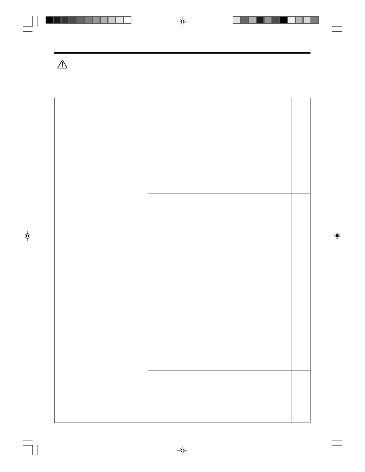
TROUBLESHOOTING
WARNING!
Symptom
Doesn’t operate immediately:
Noise is heard:
Smells:
Mist or steam are
emitted:
Airflow is weak or stops:
Water is produced from
the outdoor unit:
Problem
● If the unit is stopped and then immediately started again, the compressor will not operate for about 3 minutes, in order to prevent
fuse blowouts.
●
Whenever the Power Supply Plug is disconnected and then reconnected to a power outlet, the protection circuit will operate for
about 3 minutes, preventing unit operation during that period.
● During operation and immediately after stopping the unit, the
sound of water flowing in the air conditioner’s piping may be
heard. Also, noise may be particularly noticeable for about 2 to 3
minutes after starting operation (sound of coolant flowing).
● During operation, a slight squeaking sound may be heard. This is
the result of minute expansion and contraction of the front cover
due to temperature changes.
●
During Heating operation, a sizzling sound may be heard occasional.
This sound is produced by the Automatic Defrosting operation.
● Some smell may be emitted from the indoor unit. This smell is
the result of room smells (furniture, tobacco, etc.) which have
been taken into the air conditioner.
● During Cooling or Dry operation, a thin mist may be seen emitted
from the indoor unit. This results from the sudden Cooling of
room air by the air emitted from the air conditioner, resulting in
condensation and misting.
● During Heating operation, the outdoor unit’s fan may stop, and
steam may be seen rising from the unit. This is due to Automatic
Defrosting operation.
● When Heating operation is started, fan speed is temporarily very
low, to allow internal parts to warm up.
● During Heating operation, if the room temperature rises above
the thermostat setting, the outdoor unit will stop, and the indoor
unit will operate at very low fan speed. If you wish to warm the
room further, set the thermostat for a higher setting.
● During Heating operation, the unit will temporarily stop operation (between 7 and 15 minutes) as the Automatic Defrosting mode
operates. During Automatic Defrosting operation, the OPERATION
indicator lamp will flash.
● The fan may operate at very low speed during Dry operation or
when the unit is monitoring the room’s temperature.
● During SUPER QUIET operation, the fan will operate at very low
speed.
● In the monitor AUTO operation, the fan will operate at very low
speed.
● During Heating operation, water may be produced from the outdoor unit due to Automatic Defrosting operation.
See Page
—
—
26
—
—
26
—
26
6
6
6
26
NORMAL
FUNCTION
In the event of a malfunction (burning smell, etc.), immediately stop operation, disconnect the
Power Supply Plug, and consult authorized service personnel.
Merely turning off the unit’s power switch will not completely disconnect the unit from the power
source. Always be sure to disconnect the Power Supply Plug or turn off your circuit breaker to
ensure that power is completely off.
Before requesting service, perform the following checks:
9312556014-En.pm6.5 2003.6.11, 5:08 PM25
Page 29

En-26
TROUBLESHOOTING
Symptom
Doesn’t operate at all:
Poor Cooling performance:
The unit operates
differently from the Remote
Control Unit’s setting:
See Page
—
8 - 9
—
6
5
CHECK ONCE
MORE
Items to check
● Is the Power Supply Plug disconnected its outlet?
● Has there been a power failure?
● Has a fuse blown out, or a circuit breaker been tripped?
● Is the timer operating?
● Is the Air Filter dirty?
● Air the air conditioner’s intake grille or outlet port blocked?
● Did you adjust the room temperature settings (thermostat) cor-
rectly?
● Is there a window or door open?
● In the case of Cooling operation, is a window allowing bright sun-
light to enter? (Close the curtains.)
● In the case of Cooling operation, are there heating apparatus and
computers inside the room, or are there too many people in the
room?
● Is the unit set for SUPER QUIET operation?
● Are the Remote Control Unit’s batteries dead?
● Are the Remote Control Unit’s batteries loaded properly?
OPERATING TIPS
If the problem persists after performing these checks, or if you notice burning smells, or the TIMER indicator Lamp (Fig. 2 6)
flashes, immediately stop operation, disconnect the Power Supply Plug (Fig. 1 J), and consult authorized service personnel.
Operation and Performance
Heating Performance
● This air conditioner operates on the heat-pump principle, absorbing heat from outdoor air and transferring that
heat indoors. As a result, the operating performance is
reduced as outdoor air temperature drops. If you feel that
insufficient heating performance is being produced, we
recommend you use this air conditioner in conjunction
with another kind of heating appliance.
● Heat-pump air conditioners heat your entire room by
recirculating air throughout the room, with the result that
some time may be required after first starting the air conditioner until the room is heated.
Microcomputer-controlled Automatic Defrosting
● When using the Heating mode under conditions of low
outdoor temperature and high humidity, frost may form
on the outdoor unit, resulting in reduced operating performance.
In order to prevent this kind of reduced performance, this
unit is equipped with a Microcomputer-controlled Automatic Defrosting function. If frost forms, the air conditioner will temporarily stop, and the defrosting circuit will
operate briefly (for about 7-15 minutes).
During Automatic Defrosting operation, the OPERATION
Indicator Lamp (red) will flash.
AUTO Restart
In Event of Power Interruption
● The air conditioner power has been interrupted by a
power failure. The air conditioner will then restart automatically in its previous mode when the power is restored.
● Operated by setting before the power failure.
●
If a power failure occurs during TIMER operation, the timer
will be reset and the unit will begin (or stop) operation at the
new time setting. In the event that this (kind of timer fault
occurs the TIMER Indicator Lamp will flash (see Page. 3).
● Use of other electrical appliances (electric shaver, etc.) or
nearby use of a wireless radio transmitter may cause the
air conditioner to malfunction. In this event, temporarily
disconnect the Power Supply Plug, reconnect it, and then
use the Remote Control Unit to resume operation.
9312556014-En.pm6.5 2003.6.11, 5:08 PM26
Page 30

En-27
OPERATING TIPS
Dry Mode
About 21-43 °C
About 18-32 °C
Outdoor temperature
Indoor temperature
Cooling Mode
About 21-43 °C
About 18-32 °C
Heating Mode
About –5-24 °C
About 27 °C or less
Temperature and Humidity Range
● If the air conditioner is used under higher temperature conditioner than those listed, the built-in protection circuit may
operate to prevent internal circuit damage. Also, during Cooling and Dry modes, if the unit is used under conditions of
lower temperature than those listed above, the heat-exchanger may freeze, leading to water leakage and other damage.
● Do not use this unit for any purposes other than the Cooling, Dehumidifying, and air-circulation of rooms in ordinary
dwellings.
● If the unit is used for long periods under high-humidity conditions, condensation may form on the surface of the indoor
unit, and drip onto the floor or other objects underneath. (About 80% or more)
9312556014-En.pm6.5 2003.6.11, 5:08 PM27
Page 31

MODEL
INDOOR UNIT UNIDAD INTERIOR
MODELL
INNENGERÄT APPARECCHIO INTERNO
MODÈLE
UNITÉ INTÉRIEURE ΕΣΩΤΕΡΙΚΗ ΜΟΝΑ∆Α
MODELO
OUTDOOR UNIT UNIDAD EXTERIOR
MODELLO
AUSSENGERÄT APPARECCHIO ESTERNO
ΜΟΝΤΕΛΟ
UNITÉ EXTÉRIEURE ΕΞΩΤΕΡΙΚΗ ΜΟΝΑ∆Α
PRESIÓN MÁX.
SUCCIÓN ................................................................................................. 1.160 kPa
DESCARGA .............................................................................................. 4.120 kPa
REFRIGERANTE ........................................................................................ R410A 950 g
DIMENSIONES Y PESO
UNIDAD INTERIOR
Altura/anchura/profundidad ................................................. 280/790/230 mm
Peso ............................................................................................ 9,0 kg (NETO)
UNIDAD EXTERIOR
Altura/anchura/profundidad ................................................. 535/780/250 mm
Peso ............................................................................................. 33 kg (NETO)
PRESSIONE MASSIMA
ASPIRAZIONE .......................................................................................... 1.160 kPa
EMISSIONE .............................................................................................. 4.120 kPa
REFRIGERANTE ........................................................................................ R410A 950 g
DIMENSIONI E PESO
APPARECCHIO INTERNO
Altezza × Larghezza × Profondità ......................................... 280/790/230 mm
Peso .............................................................................................. 9,0 kg (netti)
APPARECCHIO ESTERNO
Altezza × Larghezza × Profondità ......................................... 535/780/250 mm
Peso ............................................................................................... 33 kg (netti)
ΜΕΓΙΣΤΗ ΠΙΕΣΗ
ΑΝΑΡΡΟΦΗΣΗ ......................................................................................... 1.160 kPa
ΕΚΤΟΝΩΣΗ .............................................................................................. 2.700 kPa
ΨΥΚΤΙΚΟ .................................................................................................. R410A 950 g
∆ΙΑΣΤΑΣΕΙΣ ΚΑΙ ΒΑΡΟΣ
ΕΣΩΤΕΡΙΚΗ ΜΟΝΑ∆Α
ΥΨΟΣ/ΠΛΑΤΟΣ/ΒΑΘΟΣ ......................................................... 280/790/230 mm
ΒΑΡΟΣ ................................................................................... 9,0 kg (ΚΑΘΑΡΟ)
ΕΞΩΤΕΡΙΚΗ ΜΟΝΑ∆Α
ΥΨΟΣ/ΠΛΑΤΟΣ/ΒΑΘΟΣ ......................................................... 535/780/250 mm
ΒΑΡΟΣ .................................................................................... 33 kg (ΚΑΘΑΡΟ)
PRESIÓN MÁX.
SUCCIÓN ................................................................................................. 1.160 kPa
DESCARGA .............................................................................................. 4.120 kPa
REFRIGERANTE ...................................................................................... R410A 1100 g
DIMENSIONES Y PESO
UNIDAD INTERIOR
Altura/Anchura/Profundidad ................................................ 280/790/230 mm
Peso ............................................................................................ 9,0 kg (NETO)
UNIDAD EXTERIOR
Altura/Anchura/Profundidad ................................................ 535/780/250 mm
Peso .......................................................................................................... 34 kg
PRESSIONE MASSIMA
ASPIRAZIONE .......................................................................................... 1.160 kPa
EMISSIONE .............................................................................................. 4.120 kPa
REFRIGERANTE ...................................................................................... R410A 1100 g
DIMENSIONI E PESO
APPARECCHIO INTERNO
Altezza × Larghezza × Profondità ......................................... 280/790/230 mm
Peso .............................................................................................. 9,0 kg (netti)
APPARECCHIO ESTERNO
Altezza × Larghezza × Profondità ......................................... 535/780/250 mm
Peso ............................................................................................... 34 kg (netti)
ΜΕΓΙΣΤΗ ΠΙΕΣΗ
ΑΝΑΡΡΟΦΗΣΗ ......................................................................................... 1.160 kPa
ΕΚΤΟΝΩΣΗ .............................................................................................. 4.120 kPa
ΨΥΚΤΙΚΟ ................................................................................................ R410A 1100 g
∆ΙΑΣΤΑΣΕΙΣ ΚΑΙ ΒΑΡΟΣ
ΕΣΩΤΕΡΙΚΗ ΜΟΝΑ∆Α
ΥΨΟΣ/ΠΛΑΤΟΣ/ΒΑΘΟΣ ......................................................... 280/790/230 mm
ΒΑΡΟΣ ................................................................................... 9,0 kg (ΚΑΘΑΡΟ)
ΕΞΩΤΕΡΙΚΗ ΜΟΝΑ∆Α
ΥΨΟΣ/ΠΛΑΤΟΣ/ΒΑΘΟΣ ......................................................... 535/780/250 mm
ΒΑΡΟΣ .................................................................................... 34 kg (ΚΑΘΑΡΟ)
MODEL
INDOOR UNIT UNIDAD INTERIOR
MODELL
INNENGERÄT APPARECCHIO INTERNO
MODÈLE
UNITÉ INTÉRIEURE ΕΣΩΤΕΡΙΚΗ ΜΟΝΑ∆Α
MODELO
OUTDOOR UNIT UNIDAD EXTERIOR
MODELLO
AUSSENGERÄT APPARECCHIO ESTERNO
ΜΟΝΤΕΛΟ
UNITÉ EXTÉRIEURE ΕΞΩΤΕΡΙΚΗ ΜΟΝΑ∆Α
ESPECIFICACIONES
ALIMENTACIÓN ......................................................................................... 230 V~50 Hz
REFRIGERACIÓN
CAPACIDAD .......................................................
2,6 kW (Mínimo 0,5 ~Máximo 3,6 kW)
ENTRADA DE ALIMENTACIÓN ......... 0,68 kW (Mínimo 0,25 ~Máximo 1,38 kW)
CORRIENTE ...................................................................................................... 3,0 A
RAZÓN DE EFICIENCIA DE ENERGÍA ............................................................. 3,82
CALEFACCIÓN
CAPACIDAD .......................................................
3,6 kW (Mínimo 0,5 ~Máximo 6,0 kW)
ENTRADA DE ALIMENTACIÓN ..............................
0,91 kW (Mínimo 0,25 ~Máximo 1,96 kW)
CORRIENTE ...................................................................................................... 4,0 A
CORRIENTE MÁX
Refrigeración ................................................................................................... 6,0 A
Calefacción ....................................................................................................... 8,5A
DATI TECNICI
ALIMENTAZIONE ....................................................................................... 230 V~50 Hz
RAFFREDDAMENTO
CAPACITÀ .............................................. 2,6 kW (minimo 0,5 ~ massimo 3,6 kW)
CONSUMO ....................................... 0,68 kW (minimo 0,25 ~ massimo 1,38 kW)
CORRENTE ....................................................................................................... 3,0 A
RAPPORTO ENERGETICO DI EFFICIENZA...................................................... 3,82
RISCALDAMENTO
CAPACITÀ .............................................. 3,6 kW (minimo 0,5 ~ massimo 6,0 kW)
CONSUMO ....................................... 0,91 kW (minimo 0,25 ~ massimo 1,96 kW)
CORRENTE ....................................................................................................... 4,0 A
CORRENTE MASSIMA
Raffreddamento .............................................................................................. 6,0 A
Riscaldamento ................................................................................................. 8,5 A
XAPAKTHPITIKAΣTIKA
ΤΡΟΦΟ∆ΟΣΙΑ ............................................................................................. 230 V~50 Hz
ΨΥΞΗ
∆ΥΝΑΤΟΤΗΤΑ ......................................... 2,6 kW (Ελάχιστο 0,5 ~Μέγιστο 3,6 kW)
ΙΣΧΥΣ ΕΙΣΟ∆ΟΥ ............................... 0,68 kW (Ελάχιστο 0,25 ~Μέγιστο 1,38 kW)
ΡΕΥΜΑ ............................................................................................................. 3,0 A
ΣΥΝΤΕΛΕΣΤΗΣ ΑΠΟ∆ΟΣΕΩΣ ΕΝΕΡΓΕΙΑΣ ..................................................... 3,82
ΘΕΡΜΑΝΣΗ
∆ΥΝΑΤΟΤΗΤΑ ......................................... 3,6 kW (Ελάχιστο 0,5 ~Μέγιστο 6,0 kW)
ΙΣΧΥΣ ΕΙΣΟ∆ΟΥ ............................... 0,91 kW (Ελάχιστο 0,25 ~Μέγιστο 1,96 kW)
ΡΕΥΜΑ ............................................................................................................. 4,0 A
Μέγιστη Χωρητικ.τητα
Ψύξη ................................................................................................................. 6,0 A
Θέρµανση ........................................................................................................ 8,5 A
ESPECIFICACIONES
ALIMENTACIÓN ......................................................................................... 230 V~50 Hz
REFRIGERACIÓN
CAPACIDAD .............................................. 3,5 kW (Mínimo 0,9 ~Máximo 4,2 kW)
ENTRADA DE ALIMENTACIÓN ......... 1,03 kW (Mínimo 0,25 ~Máximo 1,61 kW)
CORRIENTE ...................................................................................................... 4,6 A
RAZÓN DE EFICIENCIA DE ENERGÍA ............................................................. 3,40
CALEFACCIÓN
CAPACIDAD .............................................. 4,8 kW (Mínimo 0,9 ~Máximo 6,6 kW)
ENTRADA DE ALIMENTACIÓN ........... 1,33 kW (Mínimo 0,25 ~Máximo 2,3 kW)
CORRIENTE ...................................................................................................... 5,8 A
CORRIENTE MÁX
Refrigeración ................................................................................................... 7,0 A
Calefacción .................................................................................................... 10,0 A
DATI TECNICI
ALIMENTAZIONE ....................................................................................... 230 V~50 Hz
RAFFREDDAMENTO
CAPACITÀ .............................................. 3,5 kW (minimo 0,9 ~ massimo 4,2 kW)
CONSUMO ....................................... 1,03 kW (minimo 0,25 ~ massimo 1,61 kW)
CORRENTE ....................................................................................................... 4,6 A
RAPPORTO ENERGETICO DI EFFICIENZA...................................................... 3,40
RISCALDAMENTO
CAPACITÀ .............................................. 4,8 kW (minimo 0,9 ~ massimo 6,6 kW)
CONSUMO ......................................... 1,33 kW (minimo 0,25 ~ massimo 2,3 kW)
CORRENTE ....................................................................................................... 5,8 A
CORRENTE MASSIMA
Raffreddamento .............................................................................................. 7,0 A
Riscaldamento ............................................................................................... 10,0 A
XAPAKTHPITIKAΣTIKA
ΤΡΟΦΟ∆ΟΣΙΑ ............................................................................................. 230 V~50 Hz
ΨΥΞΗ
∆ΥΝΑΤΟΤΗΤΑ ......................................... 3,5 kW (Ελάχιστο 0,9 ~Μέγιστο 4,2 kW)
ΙΣΧΥΣ ΕΙΣΟ∆ΟΥ ............................... 1,03 kW (Ελάχιστο 0,25 ~Μέγιστο 1,61 kW)
ΡΕΥΜΑ ............................................................................................................. 4,6 A
ΣΥΝΤΕΛΕΣΤΗΣ ΑΠΟ∆ΟΣΕΩΣ ΕΝΕΡΓΕΙΑΣ ..................................................... 3,40
ΘΕΡΜΑΝΣΗ
∆ΥΝΑΤΟΤΗΤΑ ......................................... 4,8 kW (Ελάχιστο 0,9 ~Μέγιστο 6,6 kW)
ΙΣΧΥΣ ΕΙΣΟ∆ΟΥ ................................. 1,33 kW (Ελάχιστο 0,25 ~Μέγιστο 2,3 kW)
ΡΕΥΜΑ ............................................................................................................. 5,8 A
Μέγιστη Χωρητικ.τητα
Ψύξη ................................................................................................................. 7,0 A
Θέρµανση ...................................................................................................... 10,0 A
AWY14LSACW
AOY14LSAWC
AWY17LSACW
AOY17LSAWC
Page 32

 Loading...