

Page 1
AIR CONDITIONER
Floor type
DESIGN & TECHNICAL MANUAL
for Extra Cold Climate Area
INDOOR
OUTDOOR
AGU9RLF
AGU12RLF
AGU15RLF
AOU9RLFFH
AOU12RLFFH
AOU15RLFFH
Page 2

1. INDOOR UNIT
FLOOR TYPE :
AGU9RLF
AGU12RLF
AGU15RLF
DTR_AG007E_01
2013.10.28
Page 3

CONTENTS
FLOOR TYPE
AGU9-15RLF
FLOOR TYPE
AGU9-15RLF
1. INDOOR UNIT
1. FEATURES
2. WIRELESS REMOTE CONTROLLER
3. SPECIFICATIONS
4. DIMENSIONS
5. WIRING DIAGRAMS
6. CAPACITY TABLE
6-1. COOLING CAPACITY
6-2. HEATING CAPACITY
7. FAN PERFORMANCE AND CAPACITY
7-1. AIR VELOCITY DISTRIBUTION
7-2. AIRFLOW
.............................................................................................................. 01 - 01
............................................... 01 - 04
..............................................................................................01 - 06
........................................................................................................01 - 07
........................................................................................01 - 08
............................................................................................01 - 09
...................................................................................... 01 - 09
........................................................................................01 - 11
..........................................01 - 13
..................................................................... 01 - 13
........................................................................................................... 01 - 14
8. OPERATION NOISE (SOUND PRESSURE)
8-1. NOISE LEVEL CURVE
....................................................................................01 - 16
................................. 01 - 16
8-2. SOUND LEVEL CHECK POINT
..................................................................... 01 - 18
9. ELECTRIC CHARACTERISTICS
10. SAFETY DEVICES
11. EXTERNAL INPUT & OUTPUT
11-1. EXTERNAL INPUT
11-2. EXTERNAL OUTPUT
12. FUNCTION SETTINGS
12-1. INDOOR UNIT (Setting by remote controller)
13. OPTIONAL PARTS
13-1. CONTROLLER
13-2. OTHERS
............................................................................................................. 01 - 30
............................................................................................ 01 - 20
............................................................... 01 - 21
...........................................................................................01 - 21
....................................................................................... 01 - 23
.................................................................................. 01 - 25
...........................................................................................01 - 30
.................................................................................................. 01 - 30
........................................................... 01 - 19
........................................... 01 - 25
Page 4
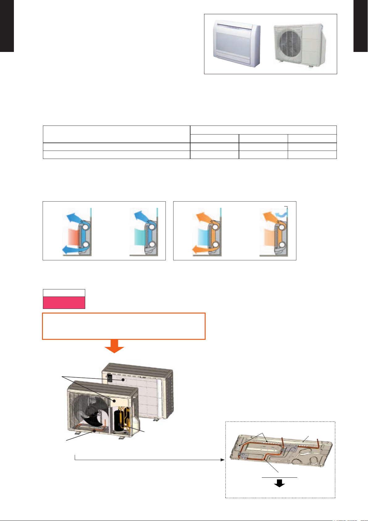
FEATURES1.
Cooling
at operation
start
Prevents cold air
from falling
at stable
operation
at operation
start
Heating
Window
Prevents cold
draft from
window
at stable
operation
Freezing prevention
150W Heater
Base
Many drain holes
MODEL
FLOOR TYPE
AGU9-15RLF
AGU9RLF / AOU9RLFFH
FLOOR TYPE
AGU9-15RLF
AGU12RLF / AOU12RLFFH
AGU15RLF / AOU15RLFFH
FEATURES
Energy efciency
z
Extra Cold Climate Area Model
AGU9RLF AGU12RLF AGU15RLF
Seasonal Energy Efciency Ratio (SEER) 26.0 22.7 20.3
Heating Seasonal Performance Factor (HSPF) 12.4 11.3 11.0
MEASUREMENT CONDITIONS
ANSI/ASHRAE STANDARD 37-1988
2-Fan & Wide airow
Structural
improvements
Low outdoor air temperature correspondence
z
Corresponds to heating operation at -15°F (-26°C) outdoor air temperature (AOU9, 12, 15RLFFH)
Heating
-15 to 75°F
(-26 to 24°C)
Specication improvement to allow operation
under extremely low outdoor temperature -15°F
(-26°C) without trouble
Extra cold climate area model
Improvement of coldproof specications of
Freezing
prevention of base
parts
- (01 - 01) -
Page 5
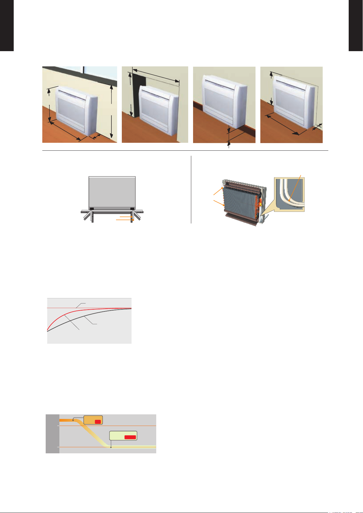
Flexible & easy installation
Fan motor
Front view
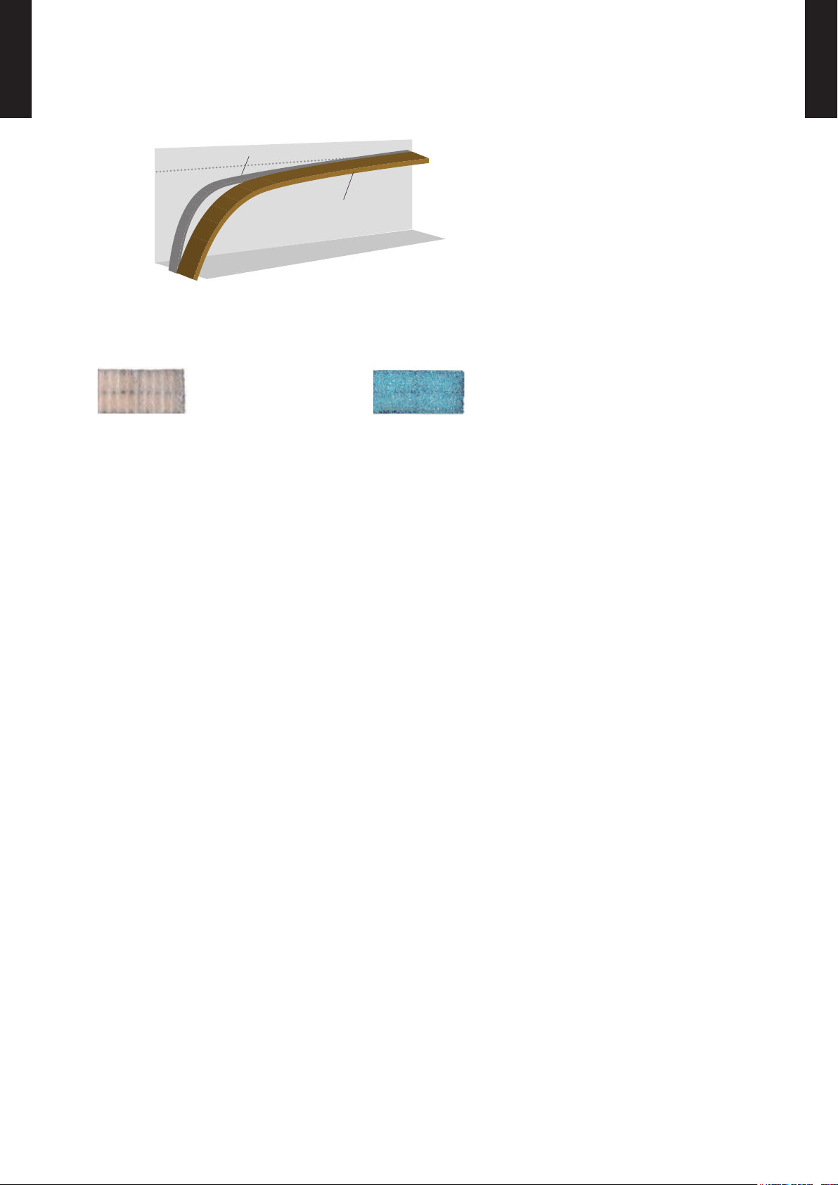
Large piping
bend R
Beneath standard window Standard concave portion
Wall
Half concealed
Unit: mm(in.) Unit: mm(in.) Unit: mm(in.) Unit: mm(in.)
600
740
(29-1/8)
200
(7-7/8)
700
(27-9/16)
Min.
700
(27-
9/16)
Min.
590
(23-
1/4)
Min. 940(37)
Max. 150
(5-7/8)
Min. 730
(28-3/4)
Max.
80
(3-1/8)
Space is wide and
piping work is easy
Choice of 6-direction drain &
piping connection
Back view
Drain hose
Piping
1
6
52
3
4
Setting temp.
Normal mode
Temperature
Powerful operation mode
“MIN. HEAT”
Button ON
Indoor unit
operation START
68
°F
(20°C)
50
°F
(10°C)
z
FLOOR TYPE
AGU9-15RLF
Piping space is wide and connection work is easy.
FLOOR TYPE
AGU9-15RLF
Super quiet operation
z
Air ow mode can be set in 4 steps and more detailed air ow setting is possible.
Powerful operation
z
Continuous operation by maximum air ow and maximum compressor speed after a certain
period of time allows the temperature to reach the setting temp. quickly.
MIN. HEAT Operation
z
The room temperature can be set to go no lower than 50°F (10°C),
thus ensuring that the room does not get too cold when not occupied
Caution)
When the room temperature is higher than 50°F (10°C), “ • MIN. HEAT” operation does not start. Operation starts and maintains the room
temperature at 50°F (10°C) when the temperature drops below 50°F (10°C).
• MIN. HEAT” operation stops, the room set temperature quickly returns to the preset temperature.
When “
*Only available with Wireless RC.
- (01 - 02) -
Page 6
Economy operation
Time
Economy operation
Normal operation
Setting
temperature
z
FLOOR TYPE
AGU9-15RLF
Limits the maximum operation current, and the power consumption is cut down and the maximum
FLOOR TYPE
AGU9-15RLF
load is suppressed.
Air conditioner lter feature
z
Apple-catechin lter Long-life ion deodorization lter
- (01 - 03) -
Page 7
WIRELESS REMOTE CONTROLLER2.
60min.
2°F (1°C)
4°F (2°C)
Timer setting
30min.
60min.
90min.
8°F
(4°C)
Timer setting
6°F
(3°C)
4°F
(2°C)
2°F
(1°C)
A B C D
A B
C
D
Mixed-up
I.U. I.U. I.U. I.U.
I.U. I.U. I.U. I.U.
After code change
REG1U
FEATURES
FLOOR TYPE
AGU9-15RLF
Simple function setting
z
4 mode timer setup available (ON / OFF / PROGRAM / SLEEP).
Easy operation.
Easy to change custom code (max. 4 custom codes) by button operation.
FLOOR TYPE
AGU9-15RLF
Setting of the air conditioner selection function is performed by remote controller.
Built-in timers
z
Select from four different timer programs (On / Off / Program / Sleep).
Program timer
z
The program timer operates the on and off timer once within a 24-hour period.
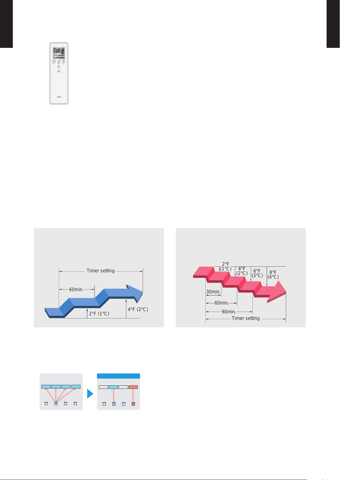
Sleep timer
z
The sleep timer function automatically corrects the temperature thermostat setting according to
the timer setting to prevent excessive cooling and heating while sleeping.
Cooling operation/dry operation
When the sleep timer is set, the set temperature
automatically rises 2°F (1°C) every hour. The set
temperature can rise up to a maximum of 4°F (2°C).
Simple function setting
z
Heating operation
When the sleep timer is set, the set temperature
automatically drops 2°F (1°C) every 30 minutes. The
set temperature can drop to a maximum of 8°F (4°C).
Setting of the air conditioner selection function is performed by remote controller.
Switching remote controller custom code
z
Code selector switch eliminates unit
•
being wrongly switched.
(Up to 4 custom codes can be set.)
*I.U.=Indoor unit
To change the temperature unit
z
Easy to change the temperature unit (
°F ↔ °C) by button operation.
- (01 - 04) -
Page 8
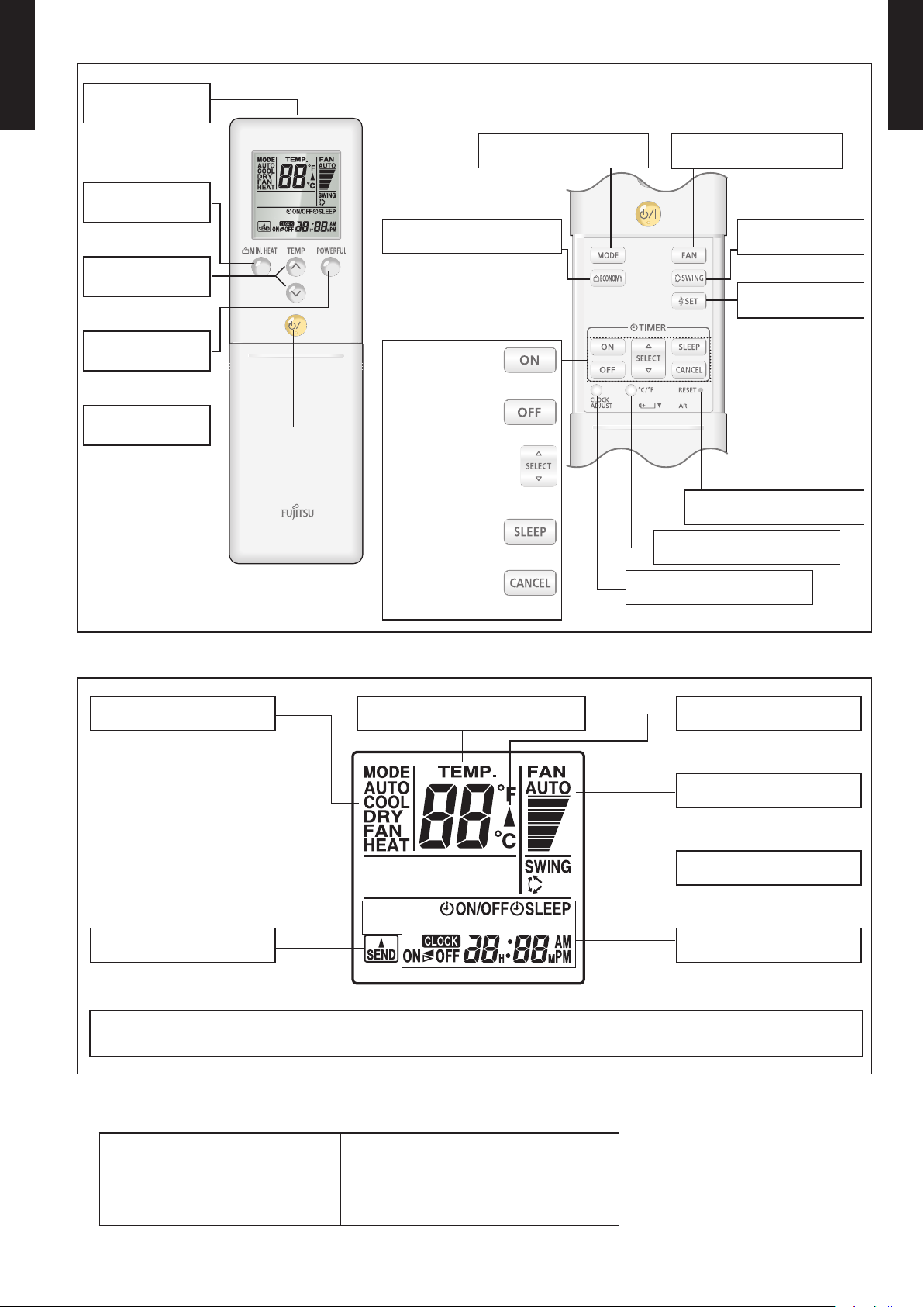
FUNCTIONS
REG1U
REG1U
Signal
FLOOR TYPE
AGU9-15RLF
transmitter
FLOOR TYPE
AGU9-15RLF
MIN. HEAT
button
TEMP.
button
POWERFUL
button
Start/Stop
button
ECONOMY button
TIMER ON button
TIMER OFF button
TIMER SELECT button
TIMER SLEEP button
TIMER CANCEL button
MODE button
CLOCK ADJUST button
FAN button
SWING button
SET button
RESET button
°C / °F switching button
Display panel
Mode indicator
Temperature indicator
Send indicator
To facilitate explanation, the accompanying illustration has been drawn to show all possible indicators; in actual operation,
however, the display will only show those indicators appropriate to the current operation.
SPECIFIC ATION
DIMENSIONS [H × W × D]: in. (mm) 8-1/16 (205) × 2-3/8 (61) × 11/16 (17)
WEIGHT oz. (g) 4.3 (122)
ACCESSORY Holder
Transmit indicator
Fan Speed indicator
Swing indicator
Clock & Timer
indicator
NOTE: Some button operations may
not be available for all units
or systems.
For details, refer to the
operation manual.
- (01 - 05) -
Page 9
SPECIFICA TIONS3.
Type
FLOOR TYPE
AGU9-15RLF
Model name AGU9RLF AGU12RLF AGU15RLF
Power sour ce 208 / 230V ~ 60Hz
Available boltage range 187 - 253V ~ 60Hz
Cooling
Capacity
Heating
Input pow er
Current
EER Cooling
COP Heating
SEER Cooling Btu/hW 26.0 22.7 20.3
HSPF Heating Btu/hW 12.4 11.3 11.0
Power fac tor
Moisture removal pints/h (l/h) 2.7 (1.3) 3.8 (1.8) 4.4 (2.1)
Maximum operating current *1
Fan
Sound pressure level
Heat excha nger ty pe
Enclosure
Dimensions
(H × W × D)
Weight
Connec tion pip e
Operation range
Remote co ntroll er type Wireless
Drain hose
Cooling
Heating
Cooling
Heating 4.1 6.7 7.0
Air ow rate
Type × Q'ty Cross o w fan × 2
Motor output W 16 × 2
Net
Gross
Net
Gross 37 (17)
Size
Method Flare
Material PP + LLDPE
Size in.(mm) Ø9/16(Ø13.8) (I.D.), Ø5/8 to Ø11/16(Ø15.8 to Ø16.7) (O.D)
Rated
Min. - Max.
Rated
Min. - Max.
Rated
Min. - Max. 0.20 - 2.05 0.20 - 2.05 0.18 - 2.16
Rated 0.88 1.44 1.58
Min. - Max. 0.20 - 2.62 0.20 - 2.62 0.18 - 3.30
Rated A
Cooling
Heating 93 93 98
Cooling
Heating
Cooling
Heating
Cooling
Heating
Dimensions
(H × W × D)
Fin pitch FPI 21
Rows × Stag es 2 × 18
Pipe type Copper
Fin type Aluminum
Material Polystyrene
Color
Liquid
Gas Ø3/8 (9.52) Ø1/2 (12.70)
Cooling
Heating °F (°C) 60 to 88 (16 to 30)
High
Med 271 (460) 306 (520)
Low 212 (360) 235 (400)
Quiet 159 (270) 159 (270)
High 353 (600) 383 (650)
Med 283 (480) 306 (520)
Low 218 (370) 230 (390)
Quiet 159 (270) 159 (270)
High
Med 35 38
Low 29 31
Quiet 23 23
High 40 43
Med 35 37
Low 29 29
Quiet 23 23
kW 2.64 3.52 4.16
Btu/h 9000 12000 14,200
kW 0.90 - 3.80 0.90 - 4.20 0.90 - 5.20
Btu/h 3100 - 13,000 3100 - 14,300 3100 - 17,700
kW 3.52 4.69 5.28
Btu/h 12000 16000 18000
kW 0.90 - 5.50 0.90 - 5.70 0.90 - 6.10
Btu/h 3100 - 18,800 3100 - 19,500 3100 - 20,800
kW
kW/kW 4.71 3.87 3.68
Btu/hW 16.0 13.1 12.5
kW/kW 4.00 3.27 3.34
Btu/hW 13.6 11.1 11.3
%
A
CFM
3
/h)
(m
dB (A)
in. (mm) 14-7/8 × 21-5/8 × 1-1/16 (378 × 550 × 26.6)
inch 23-5/8 × 29-1/8 × 7-7/8
mm 600 × 740 × 200
inch 27-9/16 × 32-5/16 × 12-3/16
mm 700 × 820 × 310
lbs. (kg)
in. (mm)
°F (°C) 64 to 90 (18 to 32)
%RH 80 or less
0.56 0.91 1.13
2.9 4.2 5.1
84 94 96
10.3 10.3 10.8
11.8 11.8 14.8
336 (570) 383 (650)
Approx imate col or of MUN SELL N9. 25/
FLOOR TYPE
INVERTER HEAT PUMP
40 44
White
31 (14)
Ø1/4 (Ø6.35)
FLOOR TYPE
AGU9-15RLF
NOTE:
Specications are based on the following conditions.
Cooling : Indoor temperature of 80°F (26.67°C) DB / 67°F (19.44°C) WB, and outdoor temperature of 95°F (35°C) DB / 75°F (23.9°C) WB.
Heating : Indoor temperature of 70°F (21.11°C) DB / 59°F (15°C) WB, and outdoor temperature of 47°F (8.33°C) DB / 43°F (6.11°C) WB.
Pipe length : 24ft.(7.5m), Height difference:0 m. (Outdoor unit-Indoor unit)
The protective function might work when using it outside the operation range.
*1: The maxim um curre nt is the ma ximum valu e when the o perated w ithin th e operat ion rang e.
- (01 - 06) -
Page 10
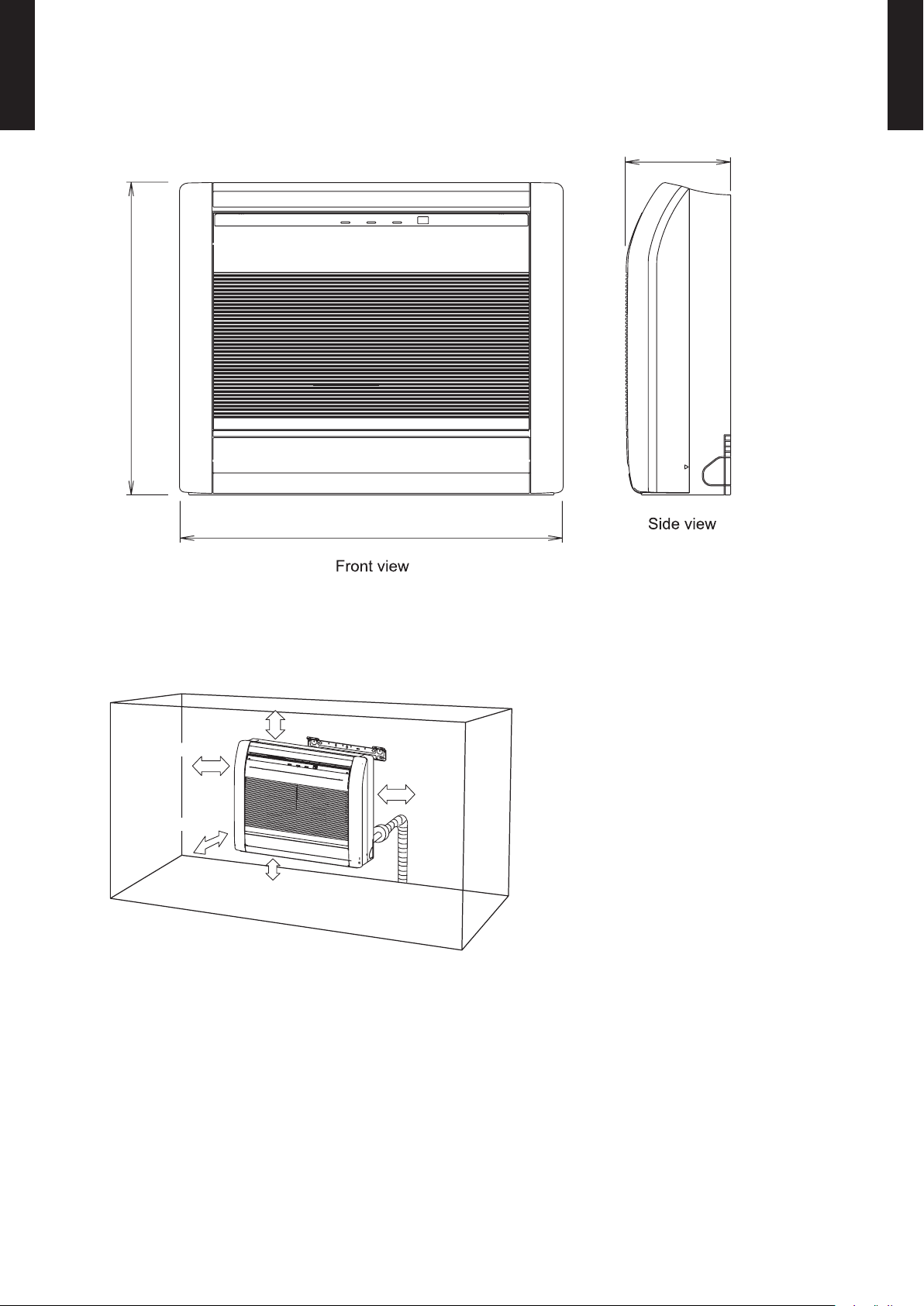
DIMENSIONS4.
29-1/8 (740)
23-5/8 (600)
7-7/8 (200)
4 (100) or more
4 (80) or more
5 (150) or below from the floor
2 (50) or more
4 (80) or more
MODEL : AGU9RLF, AGU12RLF, AGU15RLF
FLOOR TYPE
AGU9-15RLF
Unit: in. (mm)
FLOOR TYPE
AGU9-15RLF
INSTALLATION PLACE
- (01 - 07) -
Page 11
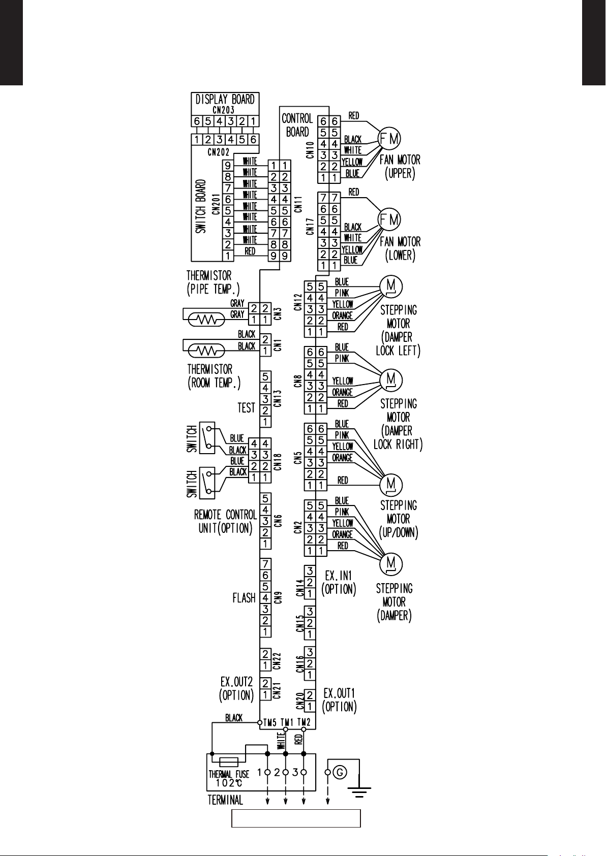
WIRING DIAGRAMS5.
TO OUTDOOR UNIT
MODEL : AGU9RLF, AGU12RLF, AGU15RLF
FLOOR TYPE
AGU9-15RLF
FLOOR TYPE
AGU9-15RLF
- (01 - 08) -
Page 12
CAPACITY TABLE6.
COOLING CAPACITY6-1.
FLOOR TYPE
AGU9-15RLF
MODEL : AGU9RLF
AFR 336
FLOOR TYPE
AGU9-15RLF
°FDB 64 70 75 80 85 90
°FWB 54 60 63 67 71 73
°FDB TC SHC IP TC SHC IP TC SHC IP TC SHC IP TC SHC IP TC SHC IP
67 6.88 6.10 0.26 7.77 6.09 0.27 8.20 6.72 0.27 8.78 7.05 0.27 9.38 7.21 0.28 9.67 8.02 0.28
77 7.79 6.88 0.44 8.80 6.87 0.45 9.28 7.58 0.45 9.93 7.95 0.45 10.62 8.14 0.46 10.95 9.04 0.46
87 7.36 6.49 0.49 8.32 6.48 0.50 8.77 7.15 0.51 9.39 7.50 0.51 10.04 7.67 0.52 10.35 8.53 0.52
95 7.06 6.23 0.54 7.97 6.22 0.55 8.41 6.86 0.55 9.00 7.20 0.56 9.62 7.37 0.57 9.92 8.19 0.57
104 6.54 5.77 0.56 7.39 5.76 0.57 7.79 6.35 0.57 8.34 6.67 0.58 8.92 6.82 0.59 9.19 7.58 0.59
Outdoor temperature
115 6.43 5.69 0.57 7.27 5.68 0.58 7.66 6.26 0.59 8.20 6.57 0.59 8.77 6.73 0.60 9.04 7.48 0.60
AFR : Air Fl ow Rate (CFM)
TC : Total Capaci ty (kBtu /h)
SHC : Sens ible Hea t Capaci ty (kBtu /h)
IP : Input Po wer (kW)
AFR 9.5
°CDB 17.8 21.1 23.9 26.7 29.4 32.2
°CWB 12.2 15.6 17.7 19.4 21.7 22.8
°CDB TC SHC IP TC SHC IP TC SHC IP TC SHC IP TC SHC IP TC SHC IP
19.4 2.02 1.79 0.26 2.28 1.79 0.27 2.40 1.97 0.27 2.57 2.07 0.27 2.75 2.11 0.28 2.83 2.35 0.28
25.0 2.28 2.02 0.44 2.58 2.01 0.45 2.72 2.22 0.45 2.91 2.33 0.45 3.11 2.38 0.46 3.21 2.65 0.46
30.6 2.16 1.90 0.49 2.44 1.90 0.50 2.57 2.09 0.51 2.75 2.20 0.51 2.94 2.25 0.52 3.03 2.50 0.52
35.0 2.07 1.83 0.54 2.34 1.82 0.55 2.46 2.01 0.55 2.64 2.11 0.56 2.82 2.16 0.57 2.91 2.40 0.57
40.0 1.92 1.69 0.56 2.17 1.69 0.57 2.28 1.86 0.57 2.44 1.95 0.58 2.61 2.00 0.59 2.69 2.22 0.59
Outdoor temperature
46.0 1.89 1.67 0.57 2.13 1.66 0.58 2.25 1.84 0.59 2.40 1.93 0.59 2.57 1.97 0.60 2.65 2.19 0.60
3
AFR : Air Fl ow Rate (m
TC : Total Capaci ty (kW)
SHC : Sens ible Hea t Capaci ty (kW)
IP : Input Po wer (kW)
/min)
Indoor temperature
Indoor temperature
MODEL : AGU12RLF
AFR 336
°FDB 64 70 75 80 85 90
°FWB 54 60 63 67 71 73
°FDB TC SHC IP TC SHC IP TC SHC IP TC SHC IP TC SHC IP TC SHC IP
67 9.18 7.71 0.42 10.37 7.70 0.43 10.93 8.50 0.44 11.70 8.91 0.44 12.51 9.12 0.45 12.90 10.14 0.45
77 10.40 8.70 0.71 11.76 8.69 0.72 12.39 9.58 0.73 13.27 10.06 0.74 14.18 10.29 0.74 14.62 11.44 0.75
87 9.82 8.23 0.80 11.10 8.22 0.82 11.70 9.07 0.82 12.52 9.52 0.83 13.39 9.74 0.84 13.80 10.82 0.85
95 9.41 7.87 0.88 10.63 7.86 0.89 11.21 8.67 0.90 12.00 9.10 0.91 12.83 9.31 0.92 13.22 10.35 0.93
104 8.74 7.31 0.91 9.87 7.30 0.93 10.41 8.05 0.94 11.14 8.45 0.95 11.91 8.65 0.96 12.28 9.61 0.96
Outdoor temperature
115 8.57 7.19 0.92 9.69 7.18 0.94 10.22 7.92 0.95 10.94 8.31 0.96 11.69 8.51 0.97 12.05 9.45 0.97
AFR : Air Fl ow Rate (CFM)
TC : Total Capaci ty (kBtu /h)
SHC : Sens ible Hea t Capaci ty (kBtu /h)
IP : Input Po wer (kW)
AFR 9.5
°CDB 17.8 21.1 23.9 26.7 29.4 32.2
°CWB 12.2 15.6 17.7 19.4 21.7 22.8
°CDB TC SHC IP TC SHC IP TC SHC IP TC SHC IP TC SHC IP TC SHC IP
19.4 2.69 2.26 0.42 3.04 2.26 0.43 3.20 2.49 0.44 3.43 2.61 0.44 3.67 2.67 0.45 3.78 2.97 0.45
25.0 3.05 2.55 0.71 3.45 2.55 0.72 3.63 2.81 0.73 3.89 2.95 0.74 4.16 3.02 0.74 4.29 3.35 0.75
30.6 2.88 2.41 0.80 3.25 2.41 0.82 3.43 2.66 0.82 3.67 2.79 0.83 3.92 2.85 0.84 4.05 3.17 0.85
35.0 2.76 2.31 0.88 3.12 2.30 0.89 3.28 2.54 0.90 3.52 2.67 0.91 3.76 2.73 0.92 3.88 3.03 0.93
40.0 2.56 2.14 0.91 2.89 2.14 0.93 3.05 2.36 0.94 3.27 2.48 0.95 3.49 2.53 0.96 3.60 2.82 0.96
Outdoor temperature
46.0 2.51 2.11 0.92 2.84 2.10 0.94 2.99 2.32 0.95 3.21 2.44 0.96 3.43 2.49 0.97 3.53 2.77 0.97
Indoor temperature
Indoor temperature
3
AFR : Air Fl ow Rate (m
TC : Total Capaci ty (kW)
SHC : Sens ible Hea t Capaci ty (kW)
IP : Input Po wer (kW)
/min)
- (01 - 09) -
Page 13
FLOOR TYPE
AGU9-15RLF
MODEL : AGU15RLF
AFR 383
FLOOR TYPE
AGU9-15RLF
°FDB 64 70 75 80 85 90
°FWB 54 60 63 67 71 73
°FDB TC SHC IP TC SHC IP TC SHC IP TC SHC IP TC SHC IP TC SHC IP
67 11.59 9.12 0.61 13.10 9.11 0.62 13.81 10.05 0.62 14.79 10.54 0.63 15.81 10.78 0.64 16.29 11.99 0.64
77 12.30 9.64 0.90 13.90 9.63 0.91 14.65 10.62 0.92 15.69 11.14 0.93 16.77 11.40 0.94 17.29 12.67 0.95
87 11.63 9.11 1.00 13.14 9.10 1.02 13.85 10.04 1.03 14.83 10.53 1.04 15.85 10.78 1.05 16.34 11.98 1.06
95 11.13 8.74 1.09 12.58 8.73 1.11 13.26 9.62 1.12 14.20 10.10 1.13 15.18 10.33 1.14 15.65 11.48 1.15
104 9.89 7.75 1.14 11.17 7.74 1.16 11.78 8.53 1.17 12.61 8.96 1.18 13.48 9.16 1.19 13.90 10.18 1.20
Outdoor temperature
115 9.33 7.31 1.15 10.54 7.30 1.17 11.12 8.05 1.18 11.90 8.45 1.19 12.72 8.65 1.20 13.11 9.61 1.21
AFR : Air Fl ow Rate (CFM)
TC : Total Capaci ty (kBtu /h)
SHC : Sens ible Hea t Capaci ty (kBtu /h)
IP : Input Po wer (kW)
AFR 10.8
°CDB 17.8 21.1 23.9 26.7 29.4 32.2
°CWB 12.2 15.6 17.7 19.4 21.7 22.8
°CDB TC SHC IP TC SHC IP TC SHC IP TC SHC IP TC SHC IP TC SHC IP
19.4 3.40 2.67 0.61 3.84 2.67 0.62 4.05 2.94 0.62 4.33 3.09 0.63 4.63 3.16 0.64 4.78 3.51 0.64
25.0 3.60 2.83 0.90 4.07 2.82 0.91 4.29 3.11 0.92 4.60 3.27 0.93 4.92 3.34 0.94 5.07 3.71 0.95
30.6 3.41 2.67 1.00 3.85 2.67 1.02 4.06 2.94 1.03 4.35 3.09 1.04 4.65 3.16 1.05 4.79 3.51 1.06
35.0 3.26 2.56 1.09 3.69 2.56 1.11 3.89 2.82 1.12 4.16 2.96 1.13 4.45 3.03 1.14 4.59 3.37 1.15
40.0 2.90 2.27 1.14 3.27 2.27 1.16 3.45 2.50 1.17 3.70 2.62 1.18 3.95 2.69 1.19 4.07 2.98 1.20
Outdoor temperature
46.0 2.73 2.14 1.15 3.09 2.14 1.17 3.26 2.36 1.18 3.49 2.48 1.19 3.73 2.53 1.20 3.84 2.82 1.21
3
AFR : Air Fl ow Rate (m
TC : Total Capaci ty (kW)
SHC : Sens ible Hea t Capaci ty (kW)
IP : Input Po wer (kW)
/min)
Indoor temperature
Indoor temperature
- (01 - 10) -
Page 14
HEATING CAPACITY6-2.
FLOOR TYPE
AGU9-15RLF
This table is created using the maximum capacity.
MODEL : AGU9RLF
AFR 353
FLOOR TYPE
AGU9-15RLF
°FDB °FWB TC IP TC IP TC IP TC IP
-15 -17 5.83 0.75 5.65 0.77 5.46 0.79 5.27 0.81
-5 -7 7.15 0.86 6.92 0.88 6.69 0.91 6.45 0.94
5 3 8.93 0.98 8.65 1.01 8.36 1.04 8.06 1.07
14 12 11.21 1.12 10.86 1.16 10.49 1.19 10.12 1.22
23 19 13.40 1.28 12.97 1.32 12.54 1.36 12.10 1.39
32 28 15.48 1.46 14.99 1.50 14.48 1.55 13.97 1.59
41 37 18.46 1.83 17.88 1.89 17.28 1.94 16.67 1.99
Outdoor temperature
47 43 17.83 1.73 17.26 1.78 16.68 1.83 16.10 1.88
50 47 20.49 1.75 19.84 1.80 19.17 1.85 18.50 1.90
59 50 20.49 1.65 19.84 1.70 19.17 1.75 18.50 1.80
AFR : Air Fl ow Rate (CFM)
TC : Total Capaci ty (kBtu /h)
IP : Input Po wer (kW)
AFR 10.0
°CDB °CWB TC IP TC IP TC IP TC IP
-26.1 -27.0 1.71 0.75 1.66 0.77 1.60 0.79 1.54 0.81
-20.6 -21.7 2.09 0.86 2.03 0.88 1.96 0.91 1.89 0.94
-15.0 -16.1 2.62 0.98 2.54 1.01 2.45 1.04 2.36 1.07
-10.0 -11.1 3.29 1.12 3.18 1.16 3.07 1.19 2.97 1.22
-5.0 -7.2 3.93 1.28 3.80 1.32 3.67 1.36 3.55 1.39
0.0 -2.2 4.54 1.46 4.39 1.50 4.24 1.55 4.10 1.59
5.0 2.8 5.41 1.83 5.24 1.89 5.06 1.94 4.89 1.99
8.3 6.1 5.22 1.73 5.06 1.78 4.89 1.83 4.72 1.88
Outdoor temperature
10.0 8.3 6.00 1.75 5.82 1.80 5.62 1.85 5.42 1.90
15.0 10.0 6.00 1.65 5.82 1.70 5.62 1.75 5.42 1.80
3
AFR : Air Fl ow Rate (m
TC : Total Capaci ty (kW)
IP : Input Po wer (kW)
/min)
°FDB 60 65 70 75
Indoor temperature
Indoor temperature
°CDB 15.6 18.3 21.1 23.9
MODEL : AGU12RLF
AFR 353
°FDB 60 65 70 75
°FDB °FWB TC IP TC IP TC IP TC IP
-15 -17 8.39 1.17 8.12 1.21 7.85 1.24 7.57 1.27
-5 -7 9.92 1.29 9.60 1.32 9.28 1.36 8.95 1.40
5 3 11.45 1.39 11.09 1.43 10.71 1.48 10.34 1.52
14 12 13.42 1.51 12.99 1.56 12.55 1.60 12.12 1.64
23 19 15.33 1.64 14.85 1.69 14.35 1.74 13.84 1.78
32 28 17.14 1.79 16.60 1.84 16.03 1.89 15.47 1.94
41 37 19.74 2.00 19.12 2.06 18.47 2.12 17.83 2.18
Outdoor temperature
47 43 19.09 1.89 18.49 1.94 17.86 2.00 17.23 2.06
50 47 21.93 1.91 21.24 1.96 20.52 2.02 19.80 2.08
59 50 21.93 1.80 21.24 1.86 20.52 1.91 19.80 1.96
AFR : Air Fl ow Rate (CFM)
TC : Total Capaci ty (kBtu /h)
IP : Input Po wer (kW)
AFR 10.0
°CDB 15.6 18.3 21.1 23.9
°CDB °CWB TC IP TC IP TC IP TC IP
-26.1 -27.0 2.46 1.17 2.38 1.21 2.30 1.24 2.22 1.27
-20.6 -21.7 2.91 1.29 2.81 1.32 2.72 1.36 2.62 1.40
-15.0 -16.1 3.36 1.39 3.25 1.43 3.14 1.48 3.03 1.52
-10.0 -11.1 3.93 1.51 3.81 1.56 3.68 1.60 3.55 1.64
-5.0 -7.2 4.49 1.64 4.35 1.69 4.20 1.74 4.06 1.78
0.0 -2.2 5.02 1.79 4.86 1.84 4.70 1.89 4.54 1.94
5.0 2.8 5.79 2.00 5.60 2.06 5.41 2.12 5.22 2.18
8.3 6.1 5.59 1.89 5.42 1.94 5.23 2.00 5.05 2.06
Outdoor temperature
10.0 8.3 6.43 1.91 6.22 1.96 6.01 2.02 5.80 2.08
15.0 10.0 6.43 1.80 6.22 1.86 6.01 1.91 5.80 1.96
3
AFR : Air Fl ow Rate (m
TC : Total Capaci ty (kW)
IP : Input Po wer (kW)
/min)
Indoor temperature
Indoor temperature
- (01 - 11) -
Page 15
FLOOR TYPE
AGU9-15RLF
MODEL : AGU15RLF
AFR 383
FLOOR TYPE
AGU9-15RLF
°FDB °FWB TC IP TC IP TC IP TC IP
-15 -17 9.26 1.52 8.97 1.56 8.67 1.60 8.36 1.65
-5 -7 11.89 1.74 11.51 1.79 11.12 1.84 10.73 1.90
5 3 14.44 1.97 13.98 2.03 13.51 2.08 13.04 2.14
14 12 17.17 2.20 16.63 2.26 16.07 2.33 15.51 2.39
23 19 19.62 2.45 19.00 2.52 18.35 2.59 17.71 2.66
32 28 22.08 2.71 21.38 2.79 20.66 2.87 19.93 2.95
41 37 22.59 2.43 21.87 2.50 20.80 2.53 19.53 2.53
Outdoor temperature
47 43 22.68 2.19 21.96 2.26 21.22 2.32 20.48 2.38
50 47 21.35 2.21 20.67 2.27 19.97 2.34 19.28 2.41
59 50 22.51 1.85 21.80 1.90 21.07 1.95 20.33 2.01
AFR : Air Fl ow Rate (CFM)
TC : Total Capaci ty (kBtu /h)
IP : Input Po wer (kW)
AFR 10.8
°CDB °CWB TC IP TC IP TC IP TC IP
-26.1 -27.0 2.71 1.52 2.63 1.56 2.54 1.60 2.45 1.65
-20.6 -21.7 3.48 1.74 3.37 1.79 3.26 1.84 3.15 1.90
-15.0 -16.1 4.23 1.97 4.10 2.03 3.96 2.08 3.82 2.14
-10.0 -11.1 5.03 2.20 4.87 2.26 4.71 2.33 4.54 2.39
-5.0 -7.2 5.75 2.45 5.57 2.52 5.38 2.59 5.19 2.66
0.0 -2.2 6.47 2.71 6.27 2.79 6.05 2.87 5.84 2.95
5.0 2.8 6.52 2.43 6.31 2.50 6.10 2.53 5.88 2.53
8.3 6.1 6.65 2.19 6.44 2.26 6.22 2.32 6.00 2.38
Outdoor temperature
10.0 8.3 6.26 2.21 6.06 2.27 5.85 2.34 5.65 2.41
15.0 10.0 6.60 1.85 6.39 1.90 6.17 1.95 5.96 2.01
3
AFR : Air Fl ow Rate (m
TC : Total Capaci ty (kW)
IP : Input Po wer (kW)
/min)
°FDB 60 65 70 75
Indoor temperature
Indoor temperature
°CDB 15.6 18.3 21.1 23.9
- (01 - 12) -
Page 16
FAN PERFORMANCE AND CAPACITY7.
0.5
UPPER
LOWER
1.0
0.5
1.0
0.5
1.0
1.0
0.5
1.0
0.5
AIR VELOCITY DISTRIBUTION7-1.
FLOOR TYPE
AGU9-15RLF
MODEL : AGU9RLF, AGU12RLF, AGU15RLF
FLOOR TYPE
AGU9-15RLF
7 2
3 1
0 0
3 1
7 2
0 1 2 3
0 3 7 10 13
7 2
3 1
0 0
3 1
Unit: ft./s (m/s)(ft.) (m)
Unit: ft./s (m/s)(ft.) (m)
Top view
Vertic al air ow direc tion lou ver: Up
Horizo ntal air ow direction l ouver: C enter
(m)
4
(ft.)
Top view
Vertic al air ow direc tion lou ver: Up
Horizo ntal air ow direction l ouver: R ight & Left
Conditions:
Fan speed: HIGH
Operation mode: FAN
Fan select: UPPER & LOWER
: UPPER FAN
: LOWER FAN
7 2
0 1 2 3
0 3 7 10 13
10 3
7 2
3 1
0 0
0 1 2 3
0 3 7 10 13
10 3
7 2
3 1
0 0
0 1 2 3
0 3 7 10 13
Unit: ft./s (m/s)(ft.) (m)
Unit: ft./s (m/s)(ft.) (m)
(m)
4
(ft.)
Top view
Vertic al air ow direc tion lou ver: Up
Horizo ntal air ow direction l ouver: C enter
(m)
4
(ft.)
Top view
Vertic al air ow direc tion lou ver: Dow n
Horizo ntal air ow direction l ouver: C enter
(m)
4
(ft.)
- (01 - 13) -
Page 17

AIRFLOW7-2.
FLOOR TYPE
AGU9-15RLF
MODEL : AGU9RLF, AGU12RLF
Cooling
z
Number of
Fan speed
rotations
[r.p.m]
(UPPER/ LOWER)
m³/h
Airow
570
FLOOR TYPE
AGU9-15RLF
HIGH
MED
LOW
QUIET
Heating
z
Fan speed
1190/1000
1000/850
820/690
660/560
Number of
rotations
[r.p.m]
(UPPER/ LOWER)
l/s
CFM
m³/h
l/s
CFM
m³/h
l/s
CFM
m³/h
l/s
CFM
m³/h
158
336
460
128
271
360
100
212
270
75
159
Airow
600
HIGH
MED
LOW
QUIET
1240/1040
1040/880
840/700
660/560
l/s
CFM
m³/h
l/s
CFM
m³/h
l/s
CFM
m³/h
l/s
CFM
167
353
480
133
283
370
103
218
270
75
159
- (01 - 14) -
Page 18

FLOOR TYPE
AGU9-15RLF
MODEL : AGU15RLF
Cooling
z
FLOOR TYPE
AGU9-15RLF
Number of
Fan speed
rotations
[r.p.m]
(UPPER/ LOWER)
m³/h
Airow
650
HIGH
MED
LOW
QUIET
Heating
z
Fan speed
1330/1120
1100/930
890/750
660/560
Number of
rotations
[r.p.m]
(UPPER/ LOWER)
l/s
CFM
m³/h
l/s
CFM
m³/h
l/s
CFM
m³/h
l/s
CFM
m³/h
181
383
520
144
306
400
111
235
270
75
159
Airow
650
HIGH
MED
LOW
QUIET
1330/1120
1100/930
860/730
660/560
l/s
CFM
m³/h
l/s
CFM
m³/h
l/s
CFM
m³/h
l/s
CFM
181
383
520
144
306
390
108
230
270
75
159
- (01 - 15) -
Page 19

OPERATION NOISE (SOUND PRESSURE)8.
High
Quiet
High
Quiet
High
Quiet
High
Quiet
NOISE LEVEL CURVE8-1.
FLOOR TYPE
AGU9-15RLF
MODEL : AGU9RLF
FLOOR TYPE
AGU9-15RLF
Cooling
z
80
70
60
50
40
30
20
Octave band sound pressure level, dB: (0 dB=0. 0002 μ bar)
10
0
63 125 250 500 1,000 2,000 4,000 8,000
Octave band center frequ ency,Hz
NC-65
NC-60
NC-55
NC-50
NC-45
NC-40
NC-35
NC-30
NC-25
NC-20
NC-15
Heating
z
80
70
60
50
40
30
20
Octave band sound pressure level, dB: (0 dB=0. 0002 μ bar)
10
0
63 125 250 500 1,000 2,000 4,000 8,000
Octave band center frequ ency,Hz
NC-65
NC-60
NC-55
NC-50
NC-45
NC-40
NC-35
NC-30
NC-25
NC-20
NC-15
MODEL : AGU12RLF
Cooling
z
80
70
60
50
40
30
20
Octave band sound pressure level, dB: (0 dB=0. 0002 μ bar)
10
NC-65
NC-60
NC-55
NC-50
NC-45
NC-40
NC-35
NC-30
NC-25
NC-20
NC-15
Heating
z
80
70
60
50
40
30
20
Octave band sound pressure level, dB: (0 dB=0. 0002 μ bar)
10
NC-65
NC-60
NC-55
NC-50
NC-45
NC-40
NC-35
NC-30
NC-25
NC-20
NC-15
0
63 125 250 500 1,000 2,000 4,000 8,000
Octave band center frequ ency,Hz
- (01 - 16) -
0
63 125 250 500 1,000 2,000 4,000 8,000
Octave band center frequ ency,Hz
Page 20

FLOOR TYPE
Quiet
High
High
Quiet
AGU9-15RLF
MODEL : AGU15RLF
FLOOR TYPE
AGU9-15RLF
Cooling
z
80
70
60
50
40
30
20
Octave band sound pressure level, dB: (0 dB=0. 0002 μ bar)
10
0
63 125 250 500 1,000 2,000 4,000 8,000
Octave band center frequ ency,Hz
NC-65
NC-60
NC-55
NC-50
NC-45
NC-40
NC-35
NC-30
NC-25
NC-20
NC-15
Heating
z
80
70
60
50
40
30
20
Octave band sound pressure level, dB: (0 dB=0. 0002 μ bar)
10
0
63 125 250 500 1,000 2,000 4,000 8,000
Octave band center frequ ency,Hz
NC-65
NC-60
NC-55
NC-50
NC-45
NC-40
NC-35
NC-30
NC-25
NC-20
NC-15
- (01 - 17) -
Page 21

SOUND LEVEL CHECK POINT8-2.
Microphone Microphone
●●Air Flow
Air Flow
39-3/8in. (1m)
39-3/8in. (1m)
FLOOR TYPE
AGU9-15RLF
FLOOR TYPE
AGU9-15RLF
- (01 - 18) -
Page 22

ELECTRIC CHARACTERISTICS9.
FLOOR TYPE
AGU9-15RLF
Model Name AGU9RLF AGU12RLF AGU15RLF
FLOOR TYPE
AGU9-15RLF
Voltage V 208 / 230 ~
Power Supply
Frequency Hz 60
Max Operating Current A 0.7
Connection Cable AWG 14
*)Wiring Spec
Limited wiring length ft. (m) 69 (21)
*) Wirin g Spec
Select ed Sampl e
(Select ed based on J apan Elec trotec hnical S tandar d and Code s Commit tee E00 05)
- (01 - 19) -
Page 23

SAFETY DEVICES10.
FLOOR TYPE
AGU9-15RLF
Protection form
Model
FLOOR TYPE
AGU9-15RLF
AGU9RLF AGU12RLF AGU15RLF
Circuit protection Current fuse (PCB)
Terminal protection Current (thermal) fuse
Fan motor protection Terminal protection program
OFF: 302 ± 27 °F (150 ± 15 °C)
ON: 248 ± 27 °F (120 ± 15 °C)
250V 3.15A
250V 3A
- (01 - 20) -
Page 24

EXTERNAL INPUT & OUTPUT11.
Indoor unit
control PC board
Connector
1
3
Signal
Field supply
*33 ft.(10 m)
Connected unit
Ex.) Switch
*: Make the distance from the PC board to the connected unit within 33 ft.(10 m).
Contact capacity: DC 24 V or more, 10 mA or more.
Operation
Stop
ON
OFF
Input signal
Indoor unit
Remote controller
ON ON ON
Input signal
ON
OFF
Indoor unit
Operation
Stop
Command
Forced stop
Normal
Remote control
operation invalidity
Connector
FLOOR TYPE
AGU9-15RLF
CN14 Control input CN20 - Operation status output
CN21 - Error status output
INPUT
OUTPUT REMARKS
See external input/output
settings for details.
FLOOR TYPE
AGU9-15RLF
EXTERNAL INPUT11-1.
CONTROL INPUT (Operation/Stop or Forced stop)
The air conditioner can be remotely operated by means of the following on-site work.
"Operation/Stop" mode or "Forced stop" mode can be selected with function setting of indoor unit.
Unit operation is started at the following contents by adding the contact input of a commercial ON/OFF switch to a
connector on the external control PC board and turning it ON.
Unit operation Initial setting after power is ON Starting mode other than initial setting
Operation mode Auto changeover Mode at previous operation
Set temperature 76°F (24°C) Temperature at previous operation
Airow mode AUTO Mode at previous operation
Up-down air direction (swing) Standard air direction (swing OFF) Air direction at previous operation
Left-right air direction (swing) Standard air direction (swing OFF) Air direction at previous operation
Circuit diagram example
z
When function setting is in "Operation/Stop" mode ●
When function setting is "Forced stop" mode ●
- (01 - 21) -
Page 25

Parts (Optional)
FLOOR TYPE
AGU9-15RLF
z
FLOOR TYPE
AGU9-15RLF
Parts name Model name
External connect kit UTY-XWZXZ5
Wire (External input) : UTY-XWZXZ5
- (01 - 22) -
Page 26

EXTERNAL OUTPUT11-2.
Field supply
Ex.)Display
Indoor unit
control PC board
Connected unit
Ex.)Relay unit
1
2
Signal
Relay
power
supply
V
Connector
*33 ft.(10 m)
DC 24 V
*: Make the distance from the PC board to the connected unit within 33 ft.(10 m).
Relay spec.: Max. DC 24 V, 10 mA to less than 500 mA.
ON
OFF
Operation
Stop
Indoor unit
Output signal
FLOOR TYPE
AGU9-15RLF
OPERATION STATUS OUTPUT
An air conditioner operation status signal can be output.
Circuit diagram example
z
FLOOR TYPE
AGU9-15RLF
Parts (Optional)
z
Wire (External output) : UTY-XWZXZ5
Parts name Model name
External connect kit UTY-XWZXZ5
- (01 - 23) -
Page 27

FLOOR TYPE
Field supply
Ex.)Display
Indoor unit
control PC board
Connected unit
Ex.)Relay unit
1
2
Signal
Relay
power
supply
V
Connector
*33 ft.(10 m)
DC 24 V
*: Make the distance from the PC board to the connected unit within 33 ft.(10 m).
Relay spec.: Max. DC 24 V, 10 mA to less than 500 mA.
ON
OFF
Error
Normal
Error status
Output signal
AGU9-15RLF
ERROR STATUS OUTPUT
FLOOR TYPE
AGU9-15RLF
An air conditioner error status signal can be output.
Circuit diagram example
z
Parts (Optional)
z
Wire (External output) : UTY-XWZXZ5
Parts name
Model name
External connect kit UTY-XWZXZ5
- (01 - 24) -
Page 28

FUNCTION SETTINGS12.
Function number
Setting
value
INDOOR UNIT (Setting by remote controller)12-1.
FLOOR TYPE
AGU9-15RLF
The function settings of the control of the indoor unit can be changed by this procedure according •
to the installation conditions. Incorrect settings can cause the indoor unit to malfunction.
After the power is turned on, perform the Function Setting according to the installation conditions
•
using the remote controller.
The settings may be selected between the following two: Function Number and Setting Value.
•
Settings will not be changed if invalid numbers or setting values are selected.
•
PREPARATION
• Before turning on the power of the indoor unit:
- Conrm whether the piping air-tight test and vacuuming have been conducted.
- Reconrm whether there is no miswiring.
• Turn on the power of the indoor units.
FUNCTION SETTING METHOD (for Wireless remote controller)
Entering the Function Setting Mode
While pressing the POWERFUL button and SET TEMP. (
•
function setting mode.
STEP 1
Setting the Remote controller Custom Code
Use the following steps to select the custom code of the remote controller. (Note
that the air conditioner cannot receive a custom code if the air conditioner has not
been set for the custom code.) The custom codes that are set through this process
are applicable only during the Function Setting process. For details on how to set
the custom codes through the normal process, refer to "REMOTE CONTROLLER
CUSTOM CODE SETTING".
Press the SET TEMP. (1
. ) ( ) button to change the custom code between →
→ → .
Match the code on the display to the air conditioner custom code. (initially set to
(If the custom code does not need to be selected, press the MIN. HEAT button and
proceed to STEP 2.)
.
Press the MODE button and check that the indoor unit can receive signals at the 2
displayed custom code.
.
Press the MIN. HEAT button to accept the custom code, and proceed to 3
) simultaneously, press the RESET button to enter the
)
STEP 2.
FLOOR TYPE
AGU9-15RLF
The air conditioner custom code is set to "A" prior to shipment.
The remote controller resets to custom code A when the batteries in the remote controller are replaced. If you use a
custom code other than custom code A, reset the custom code after replacing the batteries.
If you do not know the air conditioner custom code setting, try each of the custom codes (
you nd the code which operates the air conditioner.
STEP 2
Selecting the Function Number and Setting Value
. ) ( ) buttons to select the function number.
.
. ) ( ) buttons to select the setting value.
.
.
After turning off the power, wait 30 seconds or more before turning on it again.
The Function Setting will not become active unless the power is turned off then on again.
→ → → ) until
Press the SET TEMP. (1
(Press the MIN. HEAT button to switch between the left and right
digits.)
Press the POWERFUL button to proceed to setting the value. 2
(Press the POWERFUL button again to return to the function number
selection.)
Press the SET TEMP. (3
(Press the MIN. HEAT button to switch between the left and right
digits.)
Press the MODE button, then the START/STOP button in order to x 4
the settings.
Press the RESET button to end the function setting mode.5
After completing the Function Setting, be sure to turn off the power 6.
and turn it on again.
CAUTION
- (01 - 25) -
Page 29

FLOOR TYPE
AGU9-15RLF
FUNCTION DETAILS
Functions
1) Filter sign
2) Vertical airow direction range control
3) Room temperature control for cooling
4) Room temperature control for heating
5) Auto restart
6) Room temperature sensor switching
7) Remote controller custom code
8) External input control
9) Indoor unit fan control for energy saving for cooling
FLOOR TYPE
AGU9-15RLF
1) Filter sign
Select appropriate intervals for displaying the lter sign on the indoor unit according to the
estimated amount of dust in the air of the room.
If the indication is not required, select "No indication" (03).
(
... Factory setting)
Setting description Function number Setting value
Standard (400 hours)
Long interval (1000 hours) 01
Short interval (200 hours) 02
No indication 03
11
00
2) Vertical airow direction range control
In a concealed installation, change the setting to "Fixed" (02) to restrict the movement of the
upper air outlet so that the airow is only towards the horizontal direction.
(
... Factory setting)
Setting description Function number Setting value
Standard
(Setting prohibited) 01
Fixed (Concealed) 02
23
00
3) Room temperature control for cooling
Depending on the installed environment, correction of the room temperature sensor may be
required.
Select the appropriate control setting according to the installed environment.
(
... Factory setting)
Setting description Function number Setting value
Standard
Slightly lower control 01
Lower control 02
Higher control 03
30
00
- (01 - 26) -
Page 30

FLOOR TYPE
AGU9-15RLF
4) Room temperature control for heating
FLOOR TYPE
AGU9-15RLF
Depending on the installed environment, correction of the room temperature sensor may be
required.
Select the appropriate control setting according to the installed environment.
(
... Factory setting)
Setting description Function number Setting value
Standard
Lower control 01
Slightly higher control 02
Higher control 03
31
00
5) Auto restart
Enable or disable automatic restart after a power interruption.
(
... Factory setting)
Setting description Function number Setting value
Enable
Disable 01
40
00
* Auto restart is an emergency function such as for power outage etc.
Do not attempt to use this function in normal operation.
Be sure to operate the unit by remote controller or external input device.
6) Room temperature sensor switching
(Only for wired remote controller)
When using the Wired remote controller temperature sensor, change the setting to "Both" (01).
(
... Factory setting)
Setting description Function number Setting value
Indoor unit
Both 01
42
00
00: Sensor on the indoor unit is active.
01: Sensors on both indoor unit and wired remote controller are active.
7) Remote controller custom code
(Only for wireless remote controller)
The indoor unit custom code can be changed.
Select the appropriate custom code.
(
... Factory setting)
Setting description Function number Setting value
A
B 01
C 02
D 03
44
00
- (01 - 27) -
Page 31

FLOOR TYPE
AGU9-15RLF
8) External input control
FLOOR TYPE
AGU9-15RLF
"Operation/Stop" mode or "Forced stop" mode can be selected.
(
... Factory setting)
Setting description Function number Setting value
Operation/Stop mode
(Setting prohibited) 01
Forced stop mode 02
46
00
9) Indoor unit fan control for energy saving for cooling
Enable or disable the power-saving function by controlling the indoor unit fan rotation when the
outdoor unit is stopped during cooling operation.
(
... Factory setting)
Setting description Function number Setting value
Disable
Enable 01
49
00
00: When the outdoor unit is stopped, the indoor unit fan operates continuously following
the setting on the remote controller.
01: When the outdoor unit is stopped, the indoor unit fan operates intermittently at a very
low speed.
- (01 - 28) -
Page 32

FLOOR TYPE
AGU9-15RLF
REMOTE CONTROLLER CUSTOM CODE SETTING
Use the following steps to select the custom code of the remote controller.
(Note that the air conditioner cannot receive a signal if the right custom code has not
been set.)
Press the START/STOP button until only the clock is displayed on the remote 1
.
controller display.
.
Press the MODE button for at least ve seconds to display the current custom 2
code (initially set to ).
Press the SET TEMP. (3. ) ( ) button to change the custom code between →
→ → .
Match the code on the display to the air conditioner custom code.
.
Press the MODE button again to return to the clock display. The custom code will 4
be changed.
If no buttons are pressed within 30 seconds after the custom code is displayed, the system returns to the original
clock display. In this case, start again from step 1.
The air conditioner custom code is set to A prior to shipment.
The remote controller resets to custom code A when the batteries in the remote controller are replaced. If you use a
custom code other than custom code A, reset the custom code after replacing the batteries. If you do not know the
air conditioner custom code setting, try each of the custom codes (
operates the air conditioner.
→ → → ) until you nd the code which
FLOOR TYPE
AGU9-15RLF
REMOTE CONTROLLER TEMPERATURE UNIT
To change the temperature unit:
• Press the °C / °F switching button to select the preferred temperature unit. (Factory setting is °F.)
- (01 - 29) -
Page 33

OPTIONAL PARTS13.
Mode
Menu
Cool
Monitor
Set temp.
Fan
High
°
F
80
Mo
10:00
AM
Icon check:
CONTROLLER13-1.
FLOOR TYPE
AGU9-15RLF
Exterior Parts name Model No. Summary
Large and full-dot liquid crystal
Wired remote
controller
UTY-RVNUM
screen, wide and large keys
easy to press, user-intuitive
arrow key.
The room temperature can be
Wired remote
controller
UTY-RNNUM
controlled by detecting the
temperature accurately with
built-in thermo sensor.
Compact remote controller
Simple remote
controller
UTY-RSNUM
concentrates on the basic
functions such as Start/Stop,
Fan Control, Temperature
Setting and Operation mode.
FLOOR TYPE
AGU9-15RLF
OTHERS13-2.
Exterior Parts name Model No. Summary
( x 1 )
( x 2 )
External
connect kit
UTY-XWZXZ5
Required when external device
is connected.
- (01 - 30) -
Page 34

2. OUTDOOR UNIT
SINGLE TYPE :
AOU9RLFFH
AOU1 2RLFFH
AOU1 5RLFFH
DTR_AO148E_01
2013.10.28
Page 35

2. OUTDOOR UNIT
CONTENTS
1. SPECIFICATIONS
OUTDOOR UNIT
AOU9-15RLFFH
2. DIMENSIONS
3. REFRIGERANT CIRCUIT
4. WIRING DIAGRAMS
.............................................................................................. 02 - 01
........................................................................................................02 - 02
............................................................................ 02 - 03
........................................................................................ 02 - 05
OUTDOOR UNIT
AOU9-15RLFFH
5. CAPACITY COMPENSATION RATE FOR PIPE LENGTH
AND HEIGHT DIFFERENCE
6. ADDITIONAL CHARGE CALCULATION
7. AIRFLOW
8. OPERATION NOISE
8-1. NOISE LEVEL CURVE
8-2. SOUND LEVEL CHECK POINT
.................................................................................................................02 - 10
......................................................................................... 02 - 12
....................................................................................02 - 12
..................................................................... 02 - 07
......................................... 02 - 09
..................................................................... 02 - 14
9. ELECTRIC CHARACTERISTICS
10. SAFETY DEVICES
............................................................................................ 02 - 16
........................................................... 02 - 15
Page 36

SPECIFICA TIONS1.
Type INVERTER HEAT PUMP
Model name AOU9RLFFH AOU12RLFFH AOU15RLFFH
Beige
49 (15)
~
~
60Hz
60Hz
OUTDOOR UNIT
AOU9-15RLFFH
Power source 208 / 230V
Available voltage range 187 - 253V
Starting current A 4.1 6.7 7.0
1207 (2050) 1457 (2475) 1457 (2475)
Fan
Airow
rate
Cooling
Heating 1207 (2050) 1207 (2050) 1386 (2355)
CFM
(m
3
/h)
Type × Q'ty Propeller fan × 1
Motor output W 115
OUTDOOR UNIT
AOU9-15RLFFH
Sound pressure level
Heat exchanger type
Cooling
Heating 50 52 54
Dimensions
(H × W × D)
dB (A)
in. 23-1/8 × 34-11/16 × 1-7/16
mm 588 × 881 × 36.4
Fin pitch FPI 20
Rows × Stages 2 × 28
49 53 54
Pipe type Copper
Fin Type Aluminum
Compressor
Type × Q'ty Rotary × 1
Motor output W 850 1000
Type R410A
Refrigerant
Charge
lbs.oz. 2lbs.10oz. 2lbs.12oz.
kg 1.20 1.25
Refrigerant oil Type FREOL α68SZ
Material Steel
Enclosure
Dimensions
(H × W × D)
Weight
Net
Gross
Net
Gross 95 (43)
Size
Color
Approximate color of MUNSELL 10YR7.5/1.0
in. 24-7/16 × 31-1/8 × 11-7/16
mm 620 × 790 × 290
in. 28-1/16 × 37-3/16 × 15-9/16
mm 713 × 945 × 395
lbs.(kg)
Liquid
Gas Ø 3/8 (Ø 9.52) Ø 1/2 (Ø 12.70)
in. (mm)
86 (39) 88 (40)
Ø 1/4 (Ø 6.35)
Method Flare
Connenction pipe
Pre - charge length
Max. length 66 (20)
Min. Length 10 (3)
ft. (m)
Max. height difference 49 (15)
Operation range
Cooling
Heating -15 to 75 (-26 to 24)
°F (°C)
14 to 115 (-10 to 46)
NOTE:
Specications are based on the following conditions.
Cooling : Indoor temperature of 80°F (26.67°C) DB / 67°F (19.44°C) WB, and outdoor temperature of 95°F (35°C) DB / 75°F (23.9°C) WB.
Heating : Indoor temperature of 70°F (21.11°C) DB / 59°F (15°C) WB, and outdoor temperature of 47°F (8.33°C) DB / 43°F (6.11°C) WB.
Pipe length : 24ft.(7.5m), Height difference:0 m. (Outdoor unit - Indoor unit)
The protective function may work when using it outside the operation range.
- (02 - 01) -
Page 37

DIMENSIONS2.
4-5/16
(110)
8-1/4 (209)
6-7/8 (175)
12-5/8 (320)
4-ø7/16 (11.3) hole
21-1/4 (540)
Airflow
ø13/16 (20) hole
Bottom view
Top view
Front view Side view
2-3/16
(55)
hole
1 (25)
3/8 (10) 3/8 (10)
hole
4 (102)
3/8 (10)
1 (25)
3/8 (9)
13/16 (20)
24-7/16 (620)
31-1/8 (790)13/16 (20) 2-9/16 (65) 11/16 (18) 11-7/16 (290)
13-7/8 (352)
7/8 (23)
24 (600) or more
4 (100) or more
8 (200) or more
4 (100)
or more
10 (250) or more
(Service space)
CAUTION
In areas with heavy snowfall, if the intake and outlet of the
outdoor unit is blocked with snow, it may be difficult to
warm up and likely to cause breakdown. In such condition,
be sure to construct a canopy or baffle board stand.
MODEL : AOU9RLFFH, AOU12RLFFH, AOU15RLFFH
Unit: in. (mm)
OUTDOOR UNIT
AOU9-15RLFFH
OUTDOOR UNIT
AOU9-15RLFFH
INSTALLATION PLACE
If the space is larger than is stated, the condition will be the same as those without any no obstacles.
- (02 - 02) -
Page 38

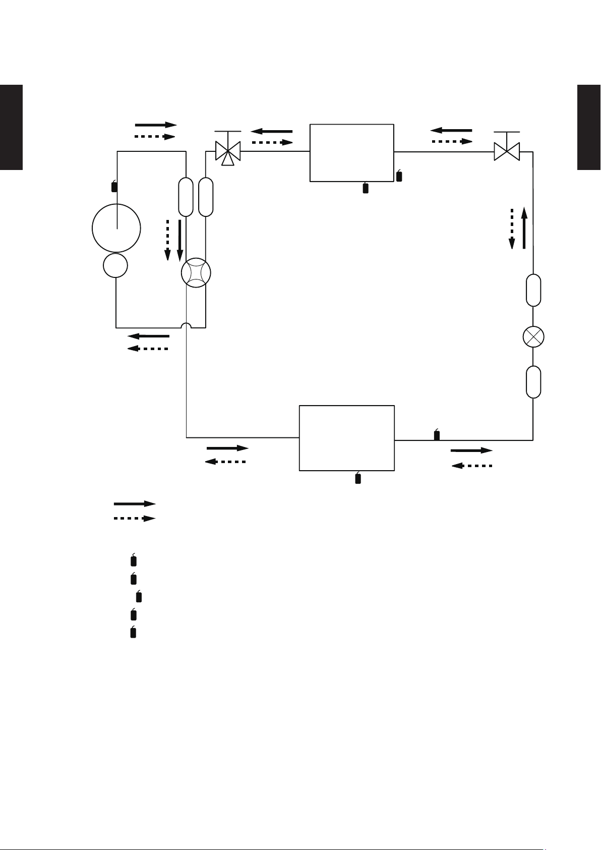
REFRIGERANT CIRCUIT3.
2-Way
valve
Strainer
Strainer
3-Way
valve
MufflerMuffler
Acccumlator
4-Way valve
Expansion valve
Heat exchanger
( INDOOR )
Heat exchanger
( OUTDOOR )
Compressor
Cooling
Heating
Refrigerant pipe diameter
Liquid: 1/4" (6.35 mm)
Gas: 3/8" (9.52 mm): 9/12RLFFH
Th
D
Th
R
Th
P
Th
HO
Th
O
: Thermistor (Discharge Temp.)
: Thermistor (Outdoor Temp.)
: Thermistor (Heat Exchanger Out Temp.)
Th
D
Th
O
Th
HO
: Thermistor (Room Temp.)
: Thermistor (Pipe Temp.)
Th
R
Th
P
MODEL : AOU9RLFFH, AOU12RLFFH
OUTDOOR UNIT
AOU9-15RLFFH
OUTDOOR UNIT
AOU9-15RLFFH
- (02 - 03) -
Page 39
MODEL : AOU1 5RLFFH
2-Way
valve
Strainer
Strainer
3-Way
valve
MufflerMuffler
4-Way valve
Expansion valve
Heat exchanger
( INDOOR )
Heat exchanger
( OUTDOOR )
Compressor
Cooling
Heating
Refrigerant pipe diameter
Liquid: 1/4" (6.35 mm)
Gas: 1/2" (12.70 mm): 15RLFFH
Th
D
Th
R
Th
P
Th
HO
Th
O
: Thermistor (Discharge Temp.)
: Thermistor (Outdoor Temp.)
: Thermistor (Heat Exchanger Out Temp.)
Th
D
Th
O
Th
HO
: Thermistor (Room Temp.)
: Thermistor (Pipe Temp.)
Th
R
Th
P
OUTDOOR UNIT
AOU9-15RLFFH
OUTDOOR UNIT
AOU9-15RLFFH
- (02 - 04) -
Page 40

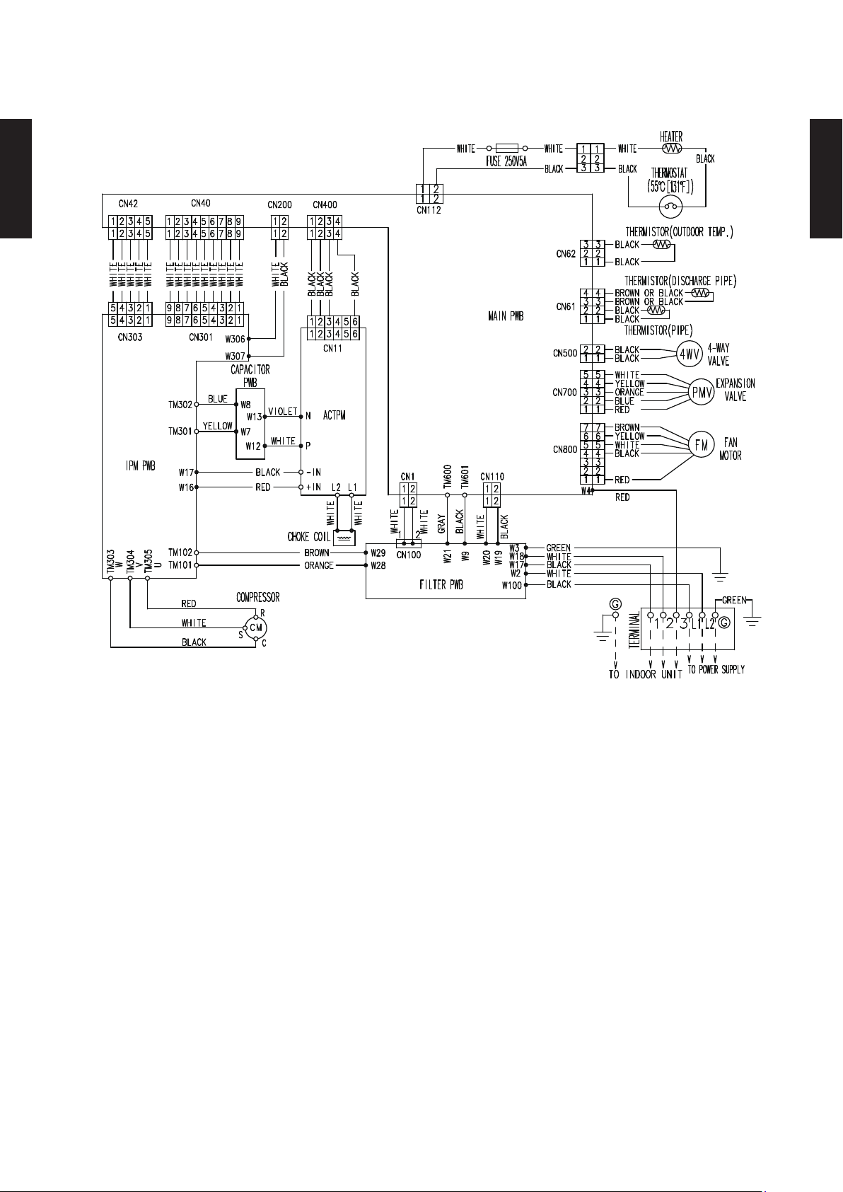
WIRING DIAGRAMS4.
MODEL : AOU9RLFFH, AOU12RLFFH
OUTDOOR UNIT
AOU9-15RLFFH
OUTDOOR UNIT
AOU9-15RLFFH
- (02 - 05) -
Page 41
MODEL : AOU1 5RLFFH
OUTDOOR UNIT
AOU9-15RLFFH
OUTDOOR UNIT
AOU9-15RLFFH
- (02 - 06) -
Page 42

CAPACITY COMPENSATION RATE FOR PIPE LENGTH 5.
AND HEIGHT DIFFERENCE
MODEL : AOU9RLFFH, AOU12RLFFH
Pipe length (m)
COOLING
OUTDOOR UNIT
AOU9-15RLFFH
Height
difference H
Height
difference H
1
Û
Indoor unit is
higher than
outdoor unit.
2
Û
Indoor unit is
lower than
outdoor unit
HEATING
1
Û
Indoor unit is
higher than
outdoor unit.
2
Û
Indoor unit is
lower than
outdoor unit
15m 50ft. - - - 0.893 0.909
10m 33ft. - - 0.955 0.908 0.924
7.5m 25ft. - 0.975 0.959 0.912 0.928
5m 17ft. 0.992 0.979 0.963 0.916 0.931
0m 0ft. 1.000 0.987 0.970 0.923 0.939
-5m -17ft. 1.000 0.987 0.970 0.923 0.939
-7.5m -25ft. - 0.987 0.970 0.923 0.939
-10m -33ft. - - 0.970 0.923 0.939
-15m -50ft. - - - 0.923 0.939
15m 50ft. - - - 0.956 0.938
10m 33ft. - - 1.004 0.956 0.938
7.5m 25ft. - 1.013 1.004 0.956 0.938
5m 17ft. 1.000 1.013 1.004 0.956 0.938
0m 0ft. 1.000 1.013 1.004 0.956 0.938
-5m -17ft. 0.995 1.008 0.999 0.951 0.933
-7.5m -25ft. - 1.005 0.997 0.948 0.931
-10m -33ft. - - 0.994 0.946 0.929
-15m -50ft. - - - 0.937 0.919
5m 7.5m 10m 15m 20m
17ft. 25ft. 33ft. 50ft. 67ft.
Pipe length (m)
5m 7.5m 10m 15m 20m
17ft. 25ft. 33ft. 50ft. 67ft.
OUTDOOR UNIT
AOU9-15RLFFH
Height difference H
Indoor unit
H
Outdoor unit
Connection pipe
1 Indoor unit is higher than outdoor unit.
Outdoor unit
H
Indoor unit
Connection pipe
2 Indoor unit is lower than outdoor unit.
- (02 - 07) -
Page 43
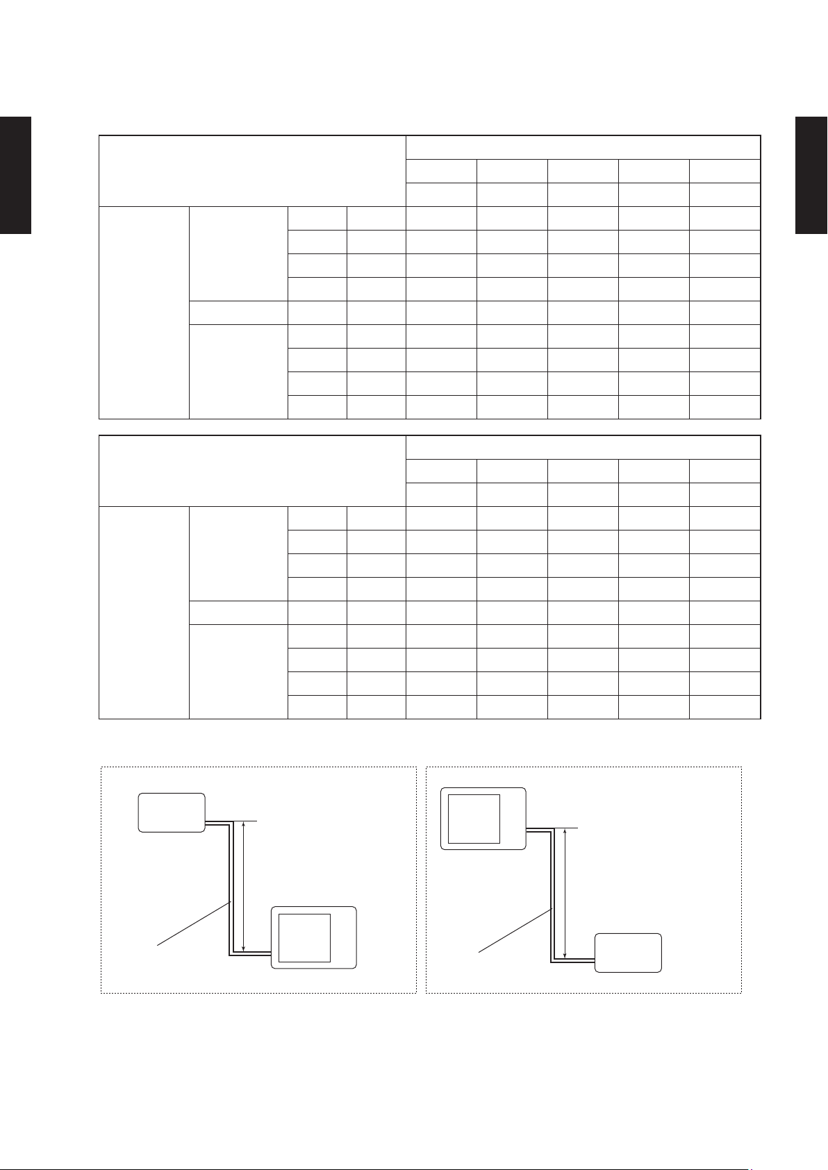
MODEL : AOU1 5RLFFH
Pipe length (m)
COOLING
OUTDOOR UNIT
AOU9-15RLFFH
Height
difference H
Height
difference H
1
Û
Indoor unit is
higher than
outdoor unit.
2
Û
Indoor unit is
lower than
outdoor unit
HEATING
1
Û
Indoor unit is
higher than
outdoor unit.
2
Û
Indoor unit is
lower than
outdoor unit
15m 50ft. - - - 0.951 0.950
10m 33ft. - - 0.979 0.967 0.966
7.5m 25ft. - 0.988 0.983 0.971 0.970
5m 17ft. 0.994 0.992 0.987 0.975 0.974
0m 0ft. 1.002 1.000 0.995 0.983 0.982
-5m -17ft. 1.002 1.000 0.995 0.983 0.982
-7.5m -25ft. - 1.000 0.995 0.983 0.982
-10m -33ft. - - 0.995 0.983 0.982
-15m -50ft. - - - 0.983 0.982
15m 50ft. - - - 0.994 0.979
10m 33ft. - - 1.012 0.994 0.979
7.5m 25ft. - 1.000 1.012 0.994 0.979
5m 17ft. 0.969 1.000 1.012 0.994 0.979
0m 0ft. 0.969 1.000 1.012 0.994 0.979
-5m -17ft. 0.964 0.995 1.007 0.989 0.974
-7.5m -25ft. - 0.993 1.004 0.986 0.972
-10m -33ft. - - 1.002 0.984 0.969
-15m -50ft. - - - 0.974 0.959
5m 7.5m 10m 15m 20m
17ft. 25ft. 33ft. 50ft. 67ft.
Pipe length (m)
5m 7.5m 10m 15m 20m
17ft. 25ft. 33ft. 50ft. 67ft.
OUTDOOR UNIT
AOU9-15RLFFH
Height difference H
Indoor unit
H
Outdoor unit
Connection pipe
1 Indoor unit is higher than outdoor unit.
Outdoor unit
H
Indoor unit
Connection pipe
2 Indoor unit is lower than outdoor unit.
- (02 - 08) -
Page 44

ADDITIONAL CHARGE CALCULATION6.
MODEL : AOU9RLFFH, AOU12RLFFH
Refrigerant type R410A
Refrigerant amount
Refrigerant charge
OUTDOOR UNIT
AOU9-15RLFFH
z
Pipe length
Additional charge
lbs. oz. 2lbs.10oz.
g 1200
ft. 49 or less 66 (MAX)
m 15 or less 20 (MAX)
oz. 0 3.5
g 0 100
0.22oz./ft.
(20g/m)
OUTDOOR UNIT
AOU9-15RLFFH
MODEL : AOU1 5RLFFH
Refrigerant type R410A
Refrigerant amount
Refrigerant charge
z
lbs. oz. 2lbs.12oz.
g 1250
Pipe length
Additional charge
ft. 49 or less 66 (MAX)
m 15 or less 20 (MAX)
oz.
g 0 100
0
3.5
0.22oz./ft.
(20g/m)
- (02 - 09) -
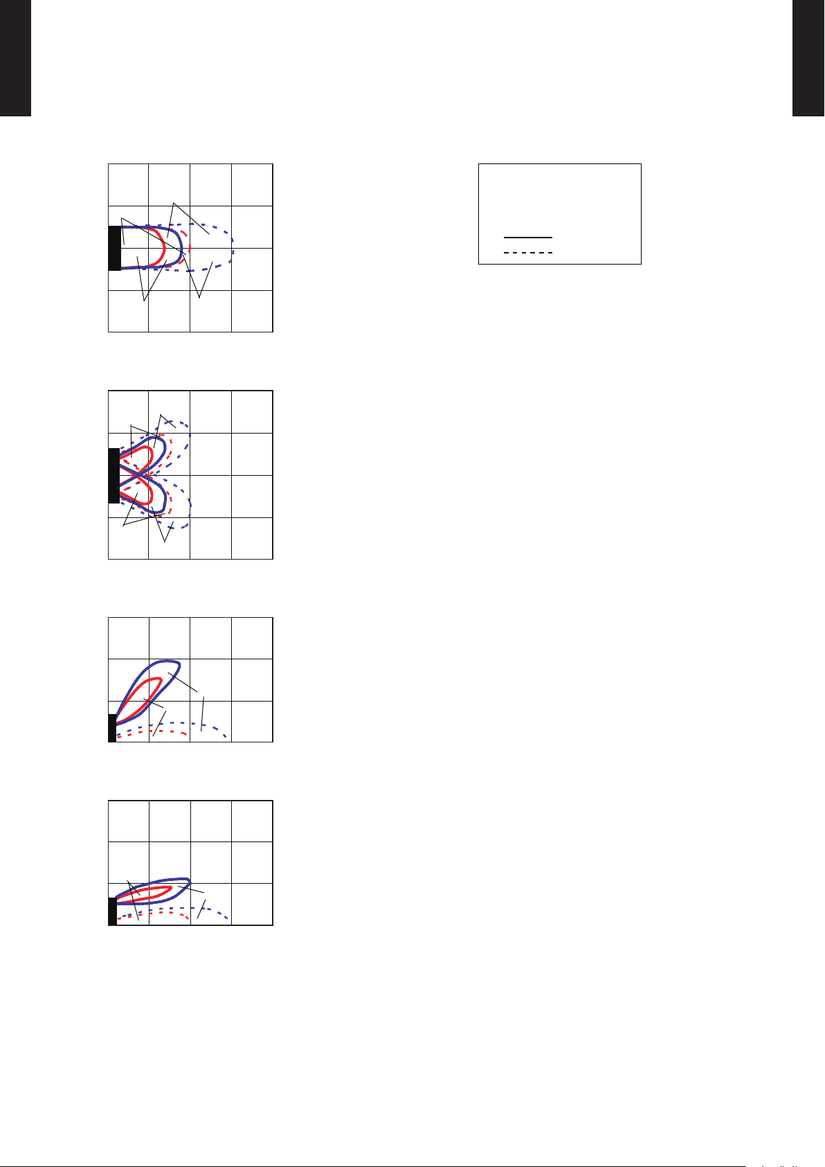
Page 45

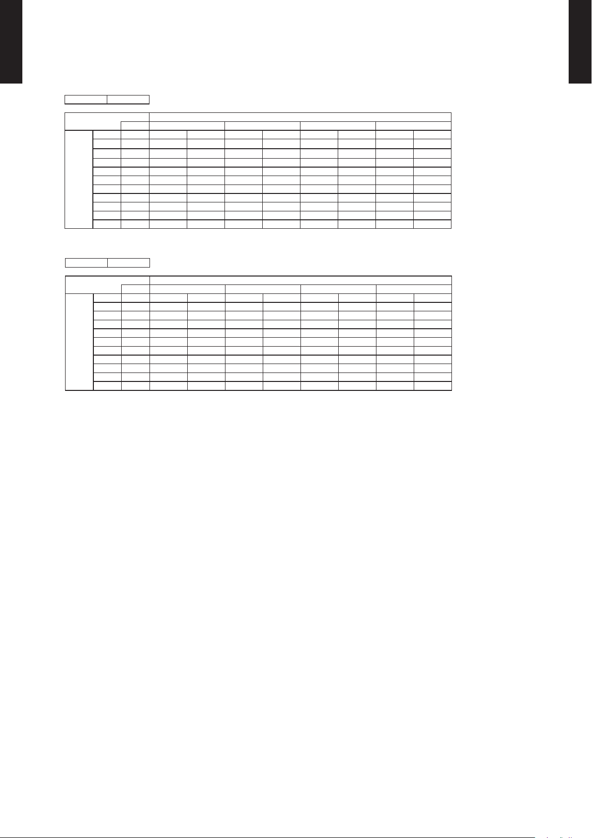
AIRFLOW7.
MODEL : AOU9RLFFH
Cooling
z
Number of
rotations
(r.p.m.)
3
m
/h 2050
Airow
OUTDOOR UNIT
AOU9-15RLFFH
870
Heating
z
Number of
rotations
(r.p.m.)
870
l/s 569
CFM 1207
Airow
3
m
/h 2050
l/s 569
CFM 1207
OUTDOOR UNIT
AOU9-15RLFFH
MODEL : AOU12RLFFH
Cooling
z
Number of
rotations
(r.p.m.)
m
Airow
3
/h 2475
1050
Heating
z
Number of
rotations
(r.p.m.)
870
l/s 688
CFM 1457
Airow
3
m
/h 2050
l/s 569
CFM 1207
- (02 - 10) -
Page 46

MODEL : AOU1 5RLFFH
Cooling
z
Number of
rotations
(r.p.m.)
3
m
/h 2475
Airow
OUTDOOR UNIT
AOU9-15RLFFH
1050
l/s 688
OUTDOOR UNIT
AOU9-15RLFFH
CFM 1457
Heating
z
Number of
rotations
Airow
(r.p.m.)
3
m
/h 2355
1000
l/s 654
CFM 1386
- (02 - 11) -
Page 47

OPERATION NOISE8.
NOISE LEVEL CURVE8-1.
MODEL : AOU9RLFFH
Cooling
z
80
70
OUTDOOR UNIT
AOU9-15RLFFH
60
50
40
30
20
Octave band sound pressure level, dB:(0dB=0.0002µbar)
10
0
63 125 250 500 1,000 2,000 4,000 8,000
Octave band center frequency,Hz
NC-65
NC-60
NC-55
NC-50
NC-45
NC-40
NC-35
NC-30
NC-25
NC-20
NC-15
Heating
z
80
70
60
50
40
30
20
Octave band sound pressure level, dB:(0dB=0.0002µbar)
10
0
63 125 250 500 1,000 2,000 4,000 8,000
Octave band center frequency,Hz
NC-65
NC-60
NC-55
NC-50
NC-45
NC-40
NC-35
NC-30
NC-25
NC-20
NC-15
OUTDOOR UNIT
AOU9-15RLFFH
MODEL : AOU12RLFFH
Cooling
z
80
70
60
50
40
30
20
Octave band sound pressure level, dB:(0dB=0.0002µbar)
10
NC-65
NC-60
NC-55
NC-50
NC-45
NC-40
NC-35
NC-30
NC-25
NC-20
NC-15
Heating
z
80
70
60
50
40
30
20
Octave band sound pressure level, dB:(0dB=0.0002µbar)
10
NC-65
NC-60
NC-55
NC-50
NC-45
NC-40
NC-35
NC-30
NC-25
NC-20
NC-15
0
63 125 250 500 1,000 2,000 4,000 8,000
Octave band center frequency,Hz
- (02 - 12) -
0
63 125 250 500 1,000 2,000 4,000 8,000
Octave band center frequency,Hz
Page 48

MODEL : AOU1 5RLFFH
Cooling
z
80
70
OUTDOOR UNIT
AOU9-15RLFFH
60
50
40
30
20
Octave band sound pressure level, dB:(0dB=0.0002µbar)
10
0
63 125 250 500 1,000 2,000 4,000 8,000
Octave band center frequency,Hz
NC-65
NC-60
NC-55
NC-50
NC-45
NC-40
NC-35
NC-30
NC-25
NC-20
NC-15
Heating
z
80
70
60
50
40
30
20
Octave band sound pressure level, dB:(0dB=0.0002µbar)
10
0
63 125 250 500 1,000 2,000 4,000 8,000
Octave band center frequency,Hz
NC-65
NC-60
NC-55
NC-50
NC-45
NC-40
NC-35
NC-30
NC-25
NC-20
NC-15
OUTDOOR UNIT
AOU9-15RLFFH
- (02 - 13) -
Page 49

SOUND LEVEL CHECK POINT8-2.
39-3/8in. (1m)
OUTDOOR UNIT
AOU9-15RLFFH
OUTDOOR UNIT
AOU9-15RLFFH
- (02 - 14) -
Page 50

ELECTRIC CHARACTERISTICS9.
Model name AOU9RLFFH AOU12RLFFH AOU15RLFFH
Power supply
MCA A
Starting Current A 4.1 6.7 7.0
*1) Wiring Spec.:
OUTDOOR UNIT
AOU9-15RLFFH
*1) Wiring Spec.:
Selected Sample
(Selected based on Japan Electrotechnical Standard and Codes Committee E0005)
MCA : Min Circuit Amp (Calculation based on UL1995)
MAX. CKT. BKR : Maximum Circuit Breaker
Voltage V 208 / 230 ~
Frequency Hz 60
11.8 14.8
MAX. CKT. BKR A 15 20
Power Cable AWG 14 12
OUTDOOR UNIT
AOU9-15RLFFH
- (02 - 15) -
Page 51

SAFETY DEVICES10.
Model
Protection form
AOU9RLFFH AOU12RLFFH AOU15RLFFH
Current fuse
(Near the terminal)
OUTDOOR UNIT
AOU9-15RLFFH
Circuit protection
Fan motor protection
Compressor protection
Current fuse
(Main printed circuit board)
Thermal protection
program
Thermal protection
program
(Discharge temp.)
250V 20A
250V 25A
250V 5A
250V 15A 250V 10A
250V 3.15A 250V 3.15A
OFF: 212 ± 27 °F (100 ± 15 °C)
ON: 203 ± 18 °F (95 ± 10 °C)
OFF: 230 °F (110 °C)
ON: After 7 minutes
OUTDOOR UNIT
AOU9-15RLFFH
- (02 - 16) -
 Loading...