

Page 1
SPLIT TYPE ROOM AIR
CONDITIONER
WALL MOUNTED TYPE
CONTENTS
SPECIFICATIONS . . . . . . . . . . . . . . . . . .
1
DIMENSIONS . . . . . . . . . . . . . . . . . . . . .
2
REFRIGERANT SYSTEM DIAGRAM . . .
3
CIRCUIT DIAGRAM. . . . . . . . . . . . . . . . .
4
ERROR DETECTION
. . . . .
5
INDOOR PCB CIRCUIT DIAGRAM
. . .
8
OUTDOOR PCB CIRCUIT DIAGRAM
. . . . . . . . . . . . . . .
10
PARTS (INDOOR UNIT). . . . . . . . . . . . .
11
PARTS (OUTDOOR UNIT). . . . . . . . . . .
15
ACCESSORIES . . . . . . . . . . . . . . . . . . .
18
Indoor unit Outdoor unit
ASU9R2 AOU9R2
ASU12R2 AOU12R2
Page 2

12010.12.10
SPECIFICATIONS
INDOOR UNIT
ASU9R2 ASU12R2
OUTDOOR UNIT AOU9R2 AOU12R2
COOLING CAPACITY
9,700 BTU/hr 12,300 BTU/hr
HEATING CAPACITY 9,600 BTU/hr 12,800 BTU/hr
POWER SOURCE 115 V 115 V
FREQUENCY 60 Hz 60 Hz
RUNNING
CURRENT
Cooling 7.6 A 9.9 A
Heating 6.5 A 9.2 A
INPUT
WATTS
Cooling 820 W 1,070 W
Heating 690 W 990 W
SEER 14.3 13.7
MOISTURE REMOVAL
2.1 Pts/hr
1.0 L/hr
3.2 Pts/hr
1.5 L/hr
AIR CIRCULATION
HIGH
329 cfm
560 m3/hr
388 cfm
660 m3/hr
ELECTRICAL DATA
COMPRESSOR AND REFRIGERANT
FAN MOTOR
DIMENSIONS
TYPE
25 ft.
7.5 m
33 ft.
10 m
41 ft.
12.5 m
49 ft.
15 m
FULL
CHARGE
Pipe length
ADDITIONAL CHARGE
MAX HEIGHT DIFFERENCE
Hermetic type,
Permanent split condenser,
2 pole, Single phase,
Induction motor
DISCRIMINATION
POWER SOURCE
EA89X1C-1FZDU1
EA118X1C-1FZDU1
115 V, 60 Hz 115 V, 60 Hz
PRECHARGED
REFRIGERANT
REFRIGERANT TYPE R410A R410A
26 ft, 8 m
0.21 oz/ft, 20 g/m
1 lb.10 oz
750 g
2 lb. 3 oz
1000 g
1 lb.10 oz
750 g
2 lb. 3 oz
1,000 g
1 lb.12 oz
800 g
2 lb. 5 oz
1,050 g
1 lb.14 oz
850 g
2 lb. 7 oz
1,100 g
2 lb.
900 g
2 lb. 9 oz
1,150 g
WEIGHT (with oil)
25 lb. 9 oz.
11.6 kg
26 lb. 7 oz.
12.0 kg
POWER SOURCE 115 V 115 V
High 1,250 r.p.m.
1,100 r.p.m.
950 r.p.m.
800 r.p.m.
640 r.p.m.
1,450 r.p.m.
1,250 r.p.m.
1,050 r.p.m.
850 r.p.m.
770 r.p.m.
INDOOR UNIT
Cool
INDOOR UNIT
Heat
Medium
Low
Quiet
High 1,250 r.p.m.
1,100 r.p.m.
970 r.p.m.
820 r.p.m.
1,400 r.p.m.
1,230 r.p.m.
1,060 r.p.m.
900 r.p.m.
Medium
Low
Quiet
OUTDOOR UNIT
INDOOR UNIT
H x W x D
H x W x D
10-13/16 x 31-1/8 x 8-15/32 inch
OUTDOOR UNIT
NOISE LEVEL
High 40 dB
36 dB
31 dB
26 dB
45 dB
45 dB
40 dB
34 dB
29 dB
46 dB
INDOOR UNIT
Cool
INDOOR UNIT
Heat
Medium
Low
Quiet
High
38 dB
34 dB
29 dB
25 dB
42 dB
37 dB
32 dB
27 dB
Medium
Low
Quiet
OUTDOOR UNIT Heat
43 dB 45 dBOUTDOOR UNIT Cool
WEIGHT
INDOOR UNIT
Shipping / Net
Shipping / Net
26lbs. / 20 lbs.
12 kg / 9 kg
OUTDOOR UNIT
79 lbs. / 71 lbs.
36 kg / 32 kg
88 lbs. / 79 lbs.
40 kg / 36 kg
275 x 790 x 215 mm
21-3/8 x 31-1/8 x 11-1/2 inch
540 x 790 x 290 mm
Page 3

2
DIMENSIONS
INDOOR UNIT
Unit : inch (mm)
OUTDOOR UNIT
Drain hose length : 22-27/32 inch (580 mm)
31-1/8 (790)
2-3/16 (56)
11/16
(17)
21-1/4 (540)
14 (356)
11-7/16 (290)
8-15/32 (215)
31-1/8 (790)
10-13/16 (275)
11-3/16 (288)
2010.12.10
Page 4

3
2005.01.21
REFRIGERANT
SYSTEM DIAGRAM
Heating
Cooling
3-Way valve
(with charging port)
4-Way
valve
Condenser
Strainer
Capillary tube
for heating and cooling
2-Way valve
Check
valve
Capillary tube for heating
(Flare connection)
Gas pipe (9.52 dia.)
(Flare connection)
(Flare connection)
Liquid pipe (6.35 dia.)
(Flare connection)
INDOOR UNIT
OUTDOOR UNIT
[ Connecting pipe ]
Evaporator
Compressor
Page 5

YELLOW
BLUE
WHITE
YELLOW
BLACK
RED
BLACK
BLACK
BLACK
BLACK
WHITE
BLACK
WHITE
RED
GREEN
BLACK
BLUE
BLACK
RED
RED
BLACK
BLACK
RED
WHITE
WHITE
BLACK
BLACK
1 2
1 2
1 2 3 4 5 6
1 2
3 456
1 2
3 4
1 2
3 4
1 2
3
1 2
3
1
2
3
1
2
3
CN11
CN13
CN12
CN2 CN1
W1
W2 W3 W4
VARISTOR
FUSE
3.15A
FUSE
5A
G
C M
COMPRESSOR
COMPRESSOR
CAPACITOR
OVERLOAD
RELAY
THERMISTOR
( OUTDOOR TEMP. )
THERMISTOR
( PIPE TEMP. )
POWER
RELAY
FM
FAN MOTORSV
4-WAY VALVE COIL
N
L
3
2
1
POWER
SOURCE
CONTROLLER PCB ASSY
SW
POWER
C
S
R
COM
ON
ORANGE
YELLOW
RED
PINK
BLUE
BLACK
BLACK
BLACK or GRAY
BLACK or GRAY
GRAY
GRAY
YELLOW
WHITE
BLACK
RED
BLUE
WHITE
WHITE
WHITE
WHITE
WHITE
WHITE
RED
1
9
7
6
5
4
3
2
8
1
3
2
1
9
7
6
5
4
3
2
8
1
7
6
5
4
3
2
1
6
5
4
3
2
1
6
5
4
3
2
1
5
4
3
2
1
5
4
3
2
1
5
4
3
2
1
5
4
3
2
1
5
4
3
2
1
1
2
3
2
1
2
CN1
CN3
CN201
CN7
CN5
CN6
CN2
CN10
LOUVER
THERMISTOR
( PIPE TEMP. )
THERMISTOR
( ROOM TEMP. )
TERMINAL
FAN MOTOR
VARISTOR
FUSE
3.15A
THERMAL
FUSE 102
WHITE
BLACK
RED
W1 W2 W3
G
1
2 3
SW
POWER
CIRCUIT
CONTROLLER PCB ASSY
( MAIN PCB )
M
FM
INDICATOR
PCB ASSY
GREEN /
YELLOW
2010.11.04 4
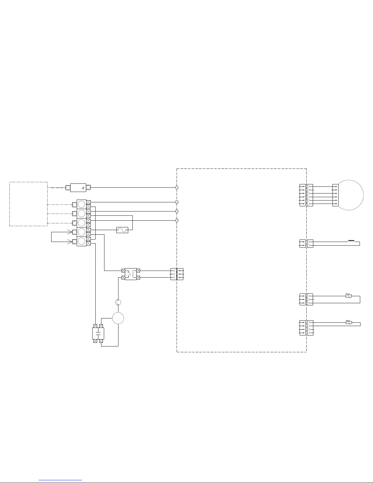
INDOOR UNIT
OUTDOOR UNIT
CIRCUIT DIAGRAM
Page 6

CN6-2 BLACK
CN6-1 BLACK
CN5-2 BLACK
CN5-1 BLACK
CN2-2 ORANGE
CN2-1 RED
CN2-3 YELLOW
CN2-4 PINK
CN2-5 BLUE
CN10-3 BLACK
CN10-2 WHITE
CN10-1 RED
CN1-3 WHITE
CN1-4 BLACK
CN1-6 RED
CN1-2 YELLOW
CN1-1 BLUE
1
2
3
4
5
6
7
8
9
1
2
3
4
5
1
2
3
4
5
1
2
3
4
5
1
3
6
5
4
3
2
1
1
2
1
2
W3
RED
W2
BLACKW1WHITE
CN3
S9B-ZR-3.4
CN6
150-503-96069
CN5
150-103-86172
CN2
53325-0560
CN1
S5 ( 6-5 ) B-XARK-1
CN3
BS5P-SHF-1AA
CN10
B05B-XASK-1-A
CN7
B03B-XASK-1-A
TERMINAL
1
2
3
4
5
6
7
THERMISTOR
( PIPE TEMP. )
THERMISTOR
( ROOM TEMP. )
LOUVER
M
F M
TEST
FAN MOTOR
CN3-1
CN3-2
CN3-3
CN3-4
CN3-5
CN201
JB20-07HG
ZHR-09
CN3-1 RED
CN3-2 WHITE
C
N
3
-
4
W
H
I
T
E
C
N
3
-
5
W
H
I
T
E
C
N
3-7
W
H
I
T
E
C
N
3-8
W
H
I
T
E
C
N
3-9
W
H
I
T
E
EARTH TERMINAL
N
L
3
N
L
SERIAL
GND
THERMAL
FUSE 103
OUTDOOR
UNIT
WIRED REMOTE
CONTROL
( OPTION )
INDICATOR PCB ASSEMBLY
K02CB-0500HSE-D0
CONTROLLER PCB ASSEMBLY
( MAIN PCB )
ASU9R2 : K04CP-0404HSE-C1
ASU12R2 : K04CP-0405HSE-C1
CONTROL UNIT
ASU9R2 : EZ-005EHSE
ASU12R2 : EZ-005FHSE
INDOOR PCB
CIRCUIT DIAGRAM
2010.11.01 5
Page 7

VA1
270V
<TNR>
F1
3.15A
250V
W2
BLACK
W1
WHITE
W3
RED
TERMINAL
3
N
L
C3
0.22
<LE>
1
14
6
10
7
5
4
1
2
2
3
2
4
3
L1
SS11V
D1
D3SB60
160V
5V
5V
20V
+
+
+
C5
150/
315V
D2
UD7G
D3
D1FL20U
R43
1.0k
<1/10W>
R44
1.0k
<1/10W>
C10
100/
35V
C6
0.1
<F>
C15
0.01
<B>
C45
0.1
<F>
T1
ETS19AB1P8AG
1
1
2
2
13.5V
C
A
REF
I C8
TL431 I LP
I C11
PS2501L-1
R11
1.0k
<1/10W>
R10
47k
<1/10W>
A
A
124
3
A
18
14
10
5
4
3
2
1
I C10
H I 1001R3
8
7
6
5
4
3
3
3
2
2
2
1
1
1
5V
D7
DAN202K
20V
15V
I C7
78M15
C16
0.1
<F>
C18
0.1
<F>
C17
330/
25V
+
123
I
G
O
R27
390
<1/10W>
C34
0.01
<B>
5V
Q2
DTC124EUA
Q1
DTC124EUA
R25
10k
<1/10W>
R26
390
<1/10W>
13.5V
12V
5V
5V
5V
5V
CN7
B03B-XASK-1-A
1 1223
3
+
+ +
I
G
O
D6
D1F60
C19
330/
25V
IC6
7805
2
1
345
VDD NC
NC
VOUT
GND
I C2
BD4842G
C20
0.1
<F>
C24
0.1
<F>
C26
0.1
<F>
C25
0.1
<F>
C23
10/
25V
C22
330/
25V
REM
W I R
61
62
63
64
65
66
73
72
76
77
78
79
80
60
27
28
29
30
31
32
34
35
1
2
3
11
12
13
14
36
37
38
39
40
41
42
15 43
16
17
18
44
45
46
47
48
8
9
10
52
53
54
55
56
49
50
51
19
20
21
22
57
58
59
5
6
71
70
23
24
25
26
69
4
67
33
74
68
75
7
P00
P01
P02
P03
P04
VDD0
VDD1
AVRF0
AVRF1
RST
P05
XT1
XT2
P10
P11
P12
P13
P14
P15
P16
P17
P50
P51
P52
P53
P54
P55
P56
P57
P60
P61
P62
P20
P21
P22
P23
P24
P25
P26
P27
P63
P64
P65
P66
P67
P70
P71
P72
P30
P31
P32
P33
P34
P35
P36
P37
P40
P41
P120
P121
P122
P123
P124
P125
P126
P127
P130
P131
P42
P43
P44
P45
P46
P47
IC
X1
X2
AGND
GND0
GND1
13
2
X1
5.00MHz
<CSTLS>
5V
5V
R22
10k
<1/10W>
C27
0.1
<F>
I C3
BR93L46RF
8
4
6
5
1
2
3
7
VCC
D0
TEST
GND
CS
SK
D1
NC
12V
BZ
R38
10K
<1/10W>
BZ1
PKM13EPY-4000-A0
11 6
R23
0R0
5V
5V
5V
JM7
JM6
JM5
JM4
JM3
JM2
5V
1
2
3
4
5
CN8
BS5P-SHF-1AA
TIMER SHORT CIRCUIT
CLOCK
DO
D I
TEST
IC13
PS2501L-1
IC12
PS2501L-1
1
2
3
Q6
DTC124EUA
5V
15V
15V
5V
C50
1000p
<R>
C62
0.1
<F>
124
3
431
2
A
A
+
DC FAN MOTOR
CN1
S5 ( 6-5 ) B-XARK-1
CN2
53325-0560
CN10
B05B-XASK-1-A
15V
160V
D50
RD27M
<B>
A
4
3
2
1
13
14
15
16
12V
5 12
5V
JP5
0R0
D61
DAN217U
D60
D1F60
12V
12V
12V
12V
12V
I C9
8
4
12V
I C4
9
8
W I R
5V
I C9-2
BA10393F
I C9-1
BA10393F
7
6
5
-
+
1
2
3
-
+
RED
WHITE
BLACK
REM
C60
1000p
<R>
C81
0.01
<B>
R61
10k
<1/10W>
R60
47
<1/10W>
5V
+
CN3
S9B-ZR-3.4
MANUAL AUTO
SWITCH
LOUVER
I C1
uPD780058BGK
C46
0.1
<F>
R42 49.9k
<1/10W>
1%
R41 10k
<1/10W>
1%
R39
10k
<1/10W>
R15 - R20
10k <1/10W> x 6
R80 - R83
10k <1/10W> x 4
R84 - R89
330 <1/10W> x 6
R28, R29
10k <1/10W> x 2
C80
100/
16V
uLN2003ADR
C91
10k
<1/10W>
1
2
3
4
5
6
7
8
9
I C4-5
uLN2003ADR
R65
10k
<1/10W>
R66
390
<1/4W>
1%
R62
10k
<1/10W>
R67
10k
<1/10W>
R68
1.0k
<1/10W>
R63 15.4k
<1/10W>
1%
R64 28k
<1/10W>
1%
1
2
3
4
5
1
2
3
4
5
6
5
4
3
2
1
C53
100/
16V
R52 820
<1/4W>
1%
R51 1.0k
<1/4W>
1%
R55
4.7k
<1/10W>
R56
6.8k
<1/4W>
R50
330
<1/10W>
R54
10k
<1/10W>
R53
1.0k
<1/10W>
I C4-4 uLN2003ADR
I C4-2 uLN2003ADR
I C4-3 uLN2003ADR
I C4-1 uLN2003ADR
R8 34k
<1/10W>
1%
R9 8.25k
<1/10W>
1%
C12
4700p
<E>
C13
330/
25V
D4
D2FL20U
C11
0.01
<F>
R5
2.0M
<1/2W>
R7
18k
<1/10W>
C7
0.01
<ECQE>
R4
100k
<RS-2W>
R2
2.2
<RGG-5W>
C33
0.01
<B>
R3
1.0k
<1/2W>
SW1
KSM0632B
R21
1.0k
<1/10W>
R24
10k
<1/10W>
I C4-6 uLN2003ADR
R34 - R37
330 <1/10W> x 4
R30 - R33
10k <1/10W> x 4
C73
10k
<1/10W>
G
CN5
150-103-86172
CN6
150-503-96069
THERMISTOR
( PIPE TEMP. )
THERMISTOR
( ROOM TEMP. )
INDICATOR PCB ASSEMBLY
WIRED REMOTE CONTROL UNIT
( OPTION )
THERMAL FUSE
INDOOR UNIT
CONTROLLER PCB ASSEMBLY ( MAIN PCB )
ASU9R2 : K04CP-0404HSE-C1
ASU12R2 : K04CP-0405HSE-C1
2010.11.01 6
I C4-7 uLN2003ADR
7 10
Page 8

5V
5V
5V
1
3
2
VCC
OUT
GND
+
I C201
GP1UM261R
C202
47/
10V
R201
47
<1/4W>
C201
0.1
<F>
CN201
07 / 09 JB20 / ZHR
1061 L=380
1
2
3
4
5
6
D204 SLR-325DC <ORG>
D203 SLR-325MC <GRN>
D202 SLR-325MC <GRN>
D201 SLR-325VC <RED>
INDOOR UNIT
INDICATOR PCB ASSEMBLY
K02CB-0500HSE-D0
2010.11.01 7
Page 9
POWER RELAY
BLACK
BLACK
BLACK
BLUEBLACKRED
WHITE
WHITE
COMPRESSOR
OVERROAD RELAY
C
R
S
C M
N
L
3
2
1
WHITE
TERMINAL
CN12
B03B-XASK-1-A
W1
W2
W3
W4
GREEN
WHITE
BLACK
RED
CN1
B06P-VL
CN2
B2P3-VH-B-C
4-WAY VALVE
1
2
CN1-2 YELLOW
CN1-1 BLUE
CN1-3 WHITE
CN1-4 BLACK
CN1-6 RED
6
5
4
3
2
1
CN11
B03B-PASK-1
CN13
B04B-PASK-1
1
3
1
2
3
4
POWER SOURCE
SERIAL
L
N
GROUND
INDOOR UNIT
CONTROLLER PCB ASSEMBLY
( MAIN PCB )
AOU9R2 : K04DK-0400HUE-C0
AOU12R2 : K04DK-0401HUE-C0
DC FAN MOTOR
F M
CN2-1 BLACK
CN2-2 BLACK
CN11-3 BLACK
CN11-1 BLACK
CN13-1 BLACK
CN13-2 BLACK
THERMISTOR
( OUTDOOR TEMP.)
THERMISTOR
( PIPE TEMP. )
1
3
FUSE
5A
250V
COMPRESSOR
CAPACITOR
CN12-1 RED
CN12-2 RED
CONTROL UNIT
AOU9R2 : EZ-004EHUE
AOU12R2 : EZ-004FHUE
OUTDOOR PCB
CIRCUIT DIAGRAM
2010.12.22 8
Page 10

5V
R28, R29
10k <1/10W> x 2
RXD
TXD
NTRL LIVE
12V
RL1
G5N-1A
1
3
4
2
RC1
RE1201
1
2
3
4
5
6
7
8
16
15
14
13
12
11
10
9
1B
2B
3B
4B
5B
6B
7B
E
1C
2C
3C
4C
5C
6C
7C
COM
G I N
I C3
uLN2003ADR
12V
5V
C25
0.1
<F>
2
1
3
4
5
VDD
VOUT
GND
NC
NC
C26
0.1
<F>
R39
10k
<1/10W>
I C2
BD4842G
GOUT
5V
R48
10k
<1/10W>
+
C23
10/
25V
C24
0.1
<F>
5V
C22
330/
25V
++
1
2
3
I
O
G
C
3
A
2
REF
1
I C8
TL431 I LP
I C6
NJM7805
5V
C20
0.1
<F>
C19
330/
25V
D6
D1F60
12V
T1
ETS19AB1P8AG
D4
D2FL20U
+
C13
330/
25V
+
R8
34k
<1/10W>
1%
R10
47k
<1/10W>
C15
0.01
<B>
R9
8.25k
<1/10W>
1%
R11
1.0k
<1/10W>
C12
4700p
<E>
I C11
PS2501L-1
A
4
312
6
5
4
1
2
10
7
20V
D3
D1FL20U
C10
100/
35V
160V
320V
C8
150/
315V
+
JM1
C9
150/
315V
+
A
5V
R21
4.7k
<1/10W>
R22
10k
<1/10W>
R24
1.0k
<1/10W>
C29
0.1
<F>
R25
1.0k
<1/10W>
C30
0.1
<F>
5V
R20, R19, R18
10k <1/10W> x 3
JM3
JM4
JM5
JM6
5V
R44
10k
<1/10W>
R42
38.3k
<1/10W>
1%
R41
4.75k
<1/10W>
1%
R43
10k
<1/10W>
C46
0.1
<F>
C45
0.1
<F>
C44
0.1
<F>
5V
X1
8.38MHz
<CSTLS>
R23
0R0
D2
UF4007
R4
100k
<RS-2W>
C7
0.01
<ECQE>
R5
2.0M
<1/2W>
R7
18k
<1/10W>
C6
0.1
<F>
I C5
TNY266PN
5
7
8
4
3
2
1
D
S
S
EN / UV
S
S
BP
1
2
3I
G
O
A
5V
I C 1
uPD780024ASGB
5V
15V
I C12
PS2501L-1
5V
C50
1000p
<R>
R53
1.0k
<1/10W>
R54
10k
<1/10W>
I C13
PS2501L-1
5V
15V
431
2
R55
4.7k
<1/10W>
R56
6.8k
<1/4W>
D50
RD27M
<B>
A
15V
320V
+
R51
1.0k
<1/4W>
1%
R52
820
<1/4W>
1%
C53
100/
16V
A
A
Q6
RT1N241M
R50
330
<1/10W>
2
1
4
3
R37, R36, R35, R34
330 <1/10W> x 4
R33, R32, R31, R30
10k <1/10W> x 4
D11
D1F60
1
2
3
4
5
6
1
2
3
4
5
1
2
3
1
2
31
28
35
36
37
38
25
24
23
22
14
15
16
17
18
19
17
12
13
33
32
30
29
9
34
21
2
3
1
44
43
42
41
40
39
8
7
6
5
4
3
2
1
52
51
50
49
48
47
46
45
26
20
10
27AVDD
VDD0
VDD1
AVREF
P40
P41
P42
P43
P44
P45
P46
P47
P50
P51
P52
P53
P54
P55
P56
P57
P70
P71
P72
P73
P74
P75
I C
RST*
P00
P01
P02
P03
P10
P11
P12
P13
P20
P21
P22
P23
P24
P25
P34
P35
P36
X1
X2
XT1
XT2
GND0
GND1
AGND
RXD
TXD
CN2
B2P3-VH-B-C
CN12
B03B-XASK-1-A
CN10
B5P-SHF-1AA
CN1
B06P-VL
CN11
B03B-PASK-1
CN13
B04B-PASK-1
20V
15V
I C7
78M15
H I C 4 H U 1 0 0 1 R 2
GOUT
+
C17
330/
25V
C18
0.1
<F>
C16
0.1
<F>
JM2, R2
330k <1/4W>
x 2
D1
D3SB60
R1
2.2
<RGG-5W>
L1
SS11V
C3
0.22
<LE>
C2
4700p
<KH>
C1
4700p
<KH>
F1
3.15A
250V
VA1
270V
<TNR>
VA2
270V
<TNR>
AR1
RA-242M
LIVE
NTRL
4
3
1
2
4
3
2
1
W2
BLACK
W1
WHITE
W3
RED
W4
GREEN
10
7
13
1
3
5
4
2
G I N
TERMINAL
2
1
3
G
2
3
1
C47
10k
<1/10W>
1
2
3
4
1
2
3
THERMISTOR ( OUTDOOR TEMP. )
THERMISTOR ( PIPE TEMP. )
POWER RELAY
TEST
DC FAN MOTOR
4-WAY VALVE
OUTDOOR UNIT
CONTROLLER PCB ASSEMBLY
AOU9R2 : K04DK-0400HUE-C0
AOU12R2 : K04DK-0401HUE-C0
2010.11.04 9
Page 11

Operation (red) Timer (green)
7 seg.
0.5 sec / twice
02
Serial (reverse) error after operation
0.5 sec / three times
03
Serial (reverse) error during operation
0.5 sec / four times
04
Serial (forward) error after operation
0.5 sec / five times
05
Serial (forward) error during operation
Room temp. thermistor error
open / short
Indoor unit
Thermistor
Heat exchange (middle) thermistor error
open / short
Heat exchange thermistor error
open
Outdoor unit
Thermistor
Outdoor temp. thermistor error
open / short
Opposite VDD permanent stop protection
(Electric aircleaner, circuit error)
Outdoor unit PCB
0.5 sec / five times
0.5 sec / six times
56
1b
Outdoor unit fan control error
0.5 sec / twice
62
Lock
0.5 sec / three times
63
r.p.m abnormal
Power supply
AA
No Indication Power supply abnormal
Model distinction
Ab
11
Model distinction error
Indoor unit fan motor
0.1 sec flashing on all LED
0.1 sec flashing on red and orange LED
Indoor unit PCB
0.5 sec / six times
0.5 sec / four times 0.5 sec / eight times
34
0.5 sec / three times
0.5 sec / four times
48
0.5 sec / three times
33
0A
21
12
Communication
0.5 sec / twice
0.5 sec / twice
22
23
0.5 sec / three times
Off
02
04
Indication on wired
remote control
06
Indication on LED
Contents
Kind of error
01
ERROR DETECTION
102005.06.10
Page 12

PARTS
12
8
9
7
13
6
3
1
4
2
3
5
10
5
11
INDOOR UNIT
Front panel assy
11
2010.11.16
3 Air Filter 9309997011
1 Front Panel Assy 9313565107
5 Grille Clamper 9306755010
4 Front Panel 9309999053
2 Intake Grille Assy 9313566074
12 Remote Control 9313693060
-- Receiver Window 9312911011
13
Remote Control Holder
9305642014
6 Louver Z Assy 9312369027
7 Louver U Assy 9312368020
8 Display Case 9311858010
9 Display PCB Assy 9705039049
10
Holder (Room Thermistor)
9311948018
Ref.Ref. Description Part number
11 Bracket Panel Assy 9310001004
Page 13

33
24
34
27
29
28
30
31
32
INDOOR UNIT
Control box
2010.11.16 12
23
22
21
26
25
28 Gear A
33 Crossflow Fan Assy
34 Bearing C Assy
25 Controller PCB Assy (9)
25
Controller PCB Assy (12)
9705712065
27 Stepping Motor
30 Fan Motor
Ref. Description Part number
9309994003
24 Switch Box Assy 9314245015
23 Switch Cover 9313943011
26 Terminal 9701955114
21 Wire Clamper 9313944018
22 Connector Cover 9313945015
9307836015
9306628017
9705712058
9900139025
9601846017
31 Motor Cushion N 9312979011
32 Motor Cushion NR 9313168018
29 Motor Clamp 9313724016
Page 14

45
44
46
43
42
41
INDOOR UNIT
Casing
2010.11.16 13
Casing Cover B45
Louver Holder Assy44 9312361014
Casing Assy41 9312112074
9314160011
Casing Cover F46 9309987005
Drain Hose Assy42 9310357026
Drain Cap Assy43 9314493010
Ref. Description Part number
Page 15

54
53
52
55
56
51
INDOOR UNIT
Evaporator
2010.11.16 14
Evaporator Holder L Assy
Joint Pipe Assy
Evaporator Holder R
Evaporator Total Assy
Evaporator Bracket
Water Seal
52
51
54
55
53
56
9314241024
9331471015
9312360024
9309983014
9312912018
9310464007
Ref. Description Part number
Page 16

152010.12.22
PARTS
OUTDOOR UNIT
6
5
2
4
12
10
10
13
11
1
9
7
3
8
6 Switch Cover 9313940010
7 Protective Net 9313941024
13 Base Assy 9316885004
12 Propeller Fan 9313808013
1 Top Panel Assy 9313988036
10 Motor Bracket Assy 9313990039
4 Cabinet Left Assy 9313991012
2 Front Panel Assy 9313972028
9 Separater C 9313934019
11 Fan Motor 9601847014
3 Emblem 9314534010
-- Drain Assy 9303029022
8 Outdoor Thermistor 9900544010
5 Cabinet Right 9313994105
Ref. Description Part number
Page 17

162010.11.17
OUTDOOR UNIT
24
23
27
25
26
32
30
31
21
22
28
29
29 Condenser Assy (9R2)
29 Condenser Assy (12R2)
9314220012
9314186011
26 Solenoid 9970048012
30 Compressor Assy (9R2)
30 Compressor Assy (12R2)
9314228018
9314200014
32 Noise Insulation B 9314530012
25 4-way Valve Assy 9314194016
27 Capillary Assy (9R2)
27 Capillary Assy (12R2)
9314225017
9314192012
23 2-way Valve Assy 9314554018
24 3-way Valve Assy 9314022012
22 Bracket Valve 9331649001
28
Heat Exchanger Thermistor
9900307011
31 Noise Insulation A 9314417023
21 Bracket Valve Cover 9331683005
Ref. Description Part number
Page 18

172010.11.17
OUTDOOR UNIT
50
48
47
49
46
45
44
42
41
43
50 Cover Terminal C 9313939014
42 Control Cover 9313936013
43 PCB Assy (9R2)
43 PCB Assy (12R2)
9705717015
9705717022
45 Capacitor Plastic 9307588167
44 Relay 9900262013
49 Bracket Conduit 9313938017
47 Terminal 9703874031
46 Capacitor Clamp 313468061808
41 Control Box Assy 9314293016
48 Bracket Terminal 9313937010
Ref. Description Part number
Page 19
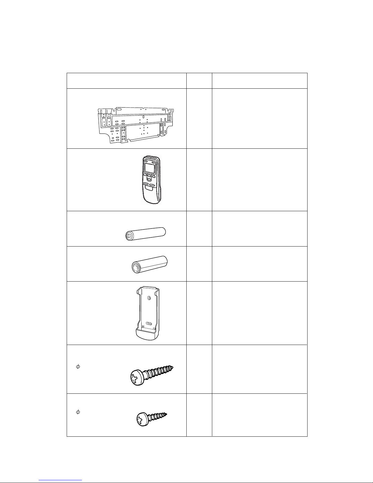
INDOOR UNIT
ACCESSORIES
Name and Shape
Wall hook bracket
Remote control
Battery (penlight)
Cloth tape
Remote control
holder
Tapping screw (big)
Tapping screw (small)
Q'ty
1
1
1
1
1
8
2
Use
To install indoor unit
9310001004
9313693060
0600185541
9310519004
9305642014
0700076046
0700019036
To operate air conditioner
For remote control
For indoor unit installation
To hold remote control
For wall hook bracket
installation
For remote control
holder installation
( 3 x 12)
( 4 x 25)
18
2010.12.22
Page 20

1011G3846
 Loading...