

Page 1
AS B09LDC
AS B12LDC
AS B18LDC
R410A
D1D_AS011E/03
2008.02.20
1. WALL MOUNTED
TYPE :
INDOOR UNIT
Page 2

- (01 - 01) -
WALL MOUNTED TYPE
AS B09-18LD
WALL MOUNTED TYPE
AS B09-18LD
MODEL : AS B09LDC
AS B12LDC
AS B18LDC
1. FEATURE
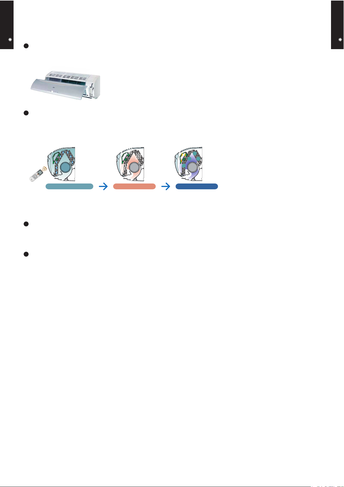
FEATURES
Original plasma air cleaning unit effectively cleans the air in the room.
Super quiet
ALL DC
More compact compared with conventional model
Front view
Air flow mode can be set in 4 steps and more detailed air flow setting is possible.
When operation starts, the machine operates at high voltage and high power
and when operation stabilizes, the set temperature is maintained at low voltage.
i-PAM control (09TYPE)
b
DC rotary compressor
c
a
DC fan motor
b
a
c
Dirty Air
Clean Air
Pet odor and the smell of
cigarette smoke are
removed by decomposition
by weak ozone O3.
Clean Air
Activated charcoal
bacteria eliminating &
deodorizing filter
Polyphenol filter
(Grapefruit seed extract)
Earth conductor
Plasma filter generates
ions and ozone.
(AO S09/12LD)
(AO S18LD)
Electric pole
Electrostatic
filter
Dirty Air
Negatively-charged dust, etc. are attracted
to the earth section and are collected by a
bacteria eliminating & deodorizing filter.
High
efficiency
layout
Plasma air filter mechanism
Washable filter
Restored to the same performance
as when new each time it is washed.
Plasma unit
Mounts a plasma air cleaning unit.Minute dust
particles are collected by an electrostatic filter and odor
is suppressed by decomposition of foul odors by very
weak ions. Since a filter with a lower ventilation
resistance than in the past is used, high dust collection
design simultaneously cleans in the air in the room.
V-PAM technology makes a compressor more powerful.
V P
V-P
V-PAM control (12/18TYPE)
a
Energy saving Rank A (09/12 TYPE) Europe energy saving Rank A achieved
Page 3
- (01 - 02) -
WALL MOUNTED TYPE
AS B09-18LD
WALL MOUNTED TYPE
AS B09-18LD
Bacteria grows in beading,
and it causes bad odor.
Drying operation for
approx. fifteen minutes.
03
030303
Ozone bacteria eliminating operation
for approx. fifteen minutes.
“Inner drying operation” and
“ozone bacteria eliminating
operation” keep the inside
of the air conditioner clean
at all times. That’s why air
from the air conditioner is
always clean and high
efficiency is realized.
After operation ends,
start approximately
30 minutes speed
cleaning operation
by merely pressing
the COIL DRY
button.
Removes moisture.
Bacteria elimination
Covered with beading.
Easy maintenance
Easy maintenance and always clean. Troublesome maintenance has been made easy.
Since the front panel is easy to remove, maintenance is also easy.
Inner drying operation and plasma effect
This model is equipped with an inner drying function. After the power is turned off, the dry operation starts
inside the air conditioner. The plasma air cleaning unit eliminates bacteria, deodorizes, and keeps
the interior of the air conditioner clean by generating ozone and ions.
Low outdoor air temperature cooling correspondence
Corresponds to cooling operation at -10
°C
outdoor air temperature
Corresponds to maximum 20m long piping
Page 4

- (01 - 03) -
WALL MOUNTED TYPE
AS B09-18LD
WALL MOUNTED TYPE
AS B09-18LD
FEATURES
Four kinds of timer setup (ON / OFF / PROGRAM / SLEEP) are possible.
Four kinds of timers. Easy operation.
Select from four different timer programs (On/Off/Program/Sleep).
Built-in timers
The program timer operates the ON and OFF timer once within a 24 hour period.
Program timer
The sleep timer function automatically corrects the temperature thermostat setting according to the
time setting to prevent excessive cooling and heating while sleeping.
Sleep timer
2-1. WIRELESS REMOTE CONTROLLER
2.
REMOTE CONTROLLER
Cooling operation/dry operation
60min.
1 °C
2 °C
When the sleep timer is set, the set temperature
automatically rises 1 °C every hour. The set
temperature can rise up to a maximum of 2 °C.
Heating operation
When the sleep timer is set, the set temperature
automatically drops 1 °C every 30 minutes. The
set temperature can drop to a maximum of 4 °C.
1 °C
30min.
60min.
90min.
2 °C
3 °C
4 °C
Timer setting
Timer setting
Page 5

- (01 - 04) -
WALL MOUNTED TYPE
AS B09-18LD
WALL MOUNTED TYPE
AS B09-18LD
Display panel
FUNCTIONS
SPECIFICATION
SIZE (H x W x D mm) 176 x 56 x 18
WEIGHT ( g ) 110
ACCESSORY Holder
TIMER SET ( / ) button
SET button
TEST RUN button
This button is used when installing the
conditioner, and should not be used under normal conditions, as it will cause the
air conditioner’s thermostat function to operate incorrectly.
If this button is pressed during normal operation, the unit will switch to test operation mode, and the Indoor Unit’s OPERATION Indicator Lamp and TIMER Indicator
Lamp will begin to flash simultaneously.
To stop the test operation mode, press the
START/STOP button to stop the air conditioner.
CLOCK ADJUST button
Remote Control Unit Display
Transmit Indicator
Clock Display
Operating Mode Display
Timer Mode Display
Fan Speed Display
Temperature SET Display
SLEEP button
MASTER CONTROL button
/ )
SET TEMP. button (
COIL DRY button
Signal Transmitter
TIMER MODE button
FAN CONTROL button
START/STOP button
SWING button
RESET button
AIR CLEAN Display
SLEEP Display
SWING Display
4
6
7
8
9
10
18
20
21
22
23
25
26
COIL DRY Display
24
19
17
2
3
11
13
12
15
16
1
14
AIR CLEAN button
5
2
4
10
3
1
15
6
17
18
19
21
25
24
22
26
13
11
12
14
9
8
7
20
5
23
16
Page 6
- (01 - 05) -
WALL MOUNTED TYPE
AS B09-18LD
WALL MOUNTED TYPE
AS B09-18LD
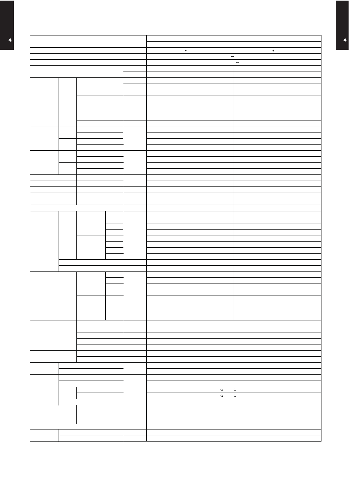
3. SPECIFICATIONS
AS B09LDC AS B12LDC
Cooling A A
Heating A A
kW 2.60 3.50
BTU/h 8,900 11,900
kW 0.5 - 3.7 0.9 - 4.3
BTU/h 1,700 - 12,600 3,100 - 14,700
kW 3.60 4.80
BTU/h 12,300 16,400
kW 0.5 - 6.1 0.9 - 6.7
BTU/h 1,700 - 20,800 3,100 - 22,900
0.61 0.91
0.25 - 1.38 0.25 - 1.61
0.81 1.22
0.25 - 1.96 0.25 - 2.30
2.9 4.3
6.0 7.0
3.9 5.5
8.5 10.0
4.26 3.85
4.44 3.93
kW 1.70 2.30
90 93
91 96
l/h (pints/h) 1.3 (2.7) 1.8 (3.8)
High 560 595
Med 470 485
Low 385 385
Quiet 260 260
High 605 630
Med 510 510
Low 410 410
Quiet 290 290
W 42 42
High 39 41
Med 34 35
Low 29 29
Quiet 20 20
High 40 41
Med 35 35
Low 28 28
Quiet 21 21
°C
%RH
°C
mm
Note :
Specifications are based on the following conditions.
Cooling : Indoor temperature of 27°CDB/19°CWB. and outdoor temperature of 35°CDB/24°CWB.
Heating : Indoor temperature of 20°CDB/15°CWB. and outdoor temperature of 7°CDB/6°CWB.
Pipe length : 7.5 m, Height difference : 0 m. (Outdoor unit - Indoor unit)
The maximum current is the maximum value when operated within the operation range (temperature).
Cross flow fan × 1
336 × 635 × 26.6
1.2
2 × 16
WALL MOUNTED
INVERTER HEAT PUMP
230V 50Hz
198 - 264V 50Hz
mm
Dimensions
(H × W × D)
PP + LLDPE
Outer diameter : 29 / Inner diameter : 13.6
Remote controller type
Drain pipe
Material
Cooling
Heating
m3/h
Operation range
kg (lb.)
Connection pipe
Size
mm
Weight
Heat exchanger type
Enclosure
Material
Colour
Net
Gross
Net
Gross
kW/kW
Cooling
Heating
%
Cooling
Heating
Cooling
Fan
Airflow
rate
Current
Cooling
SENSIBLE CAPACITY
POWER FACTOR
Min.-Max.
A
Heating
Rated
Max.
Rated
Max.
Type
Rated
Rated
Rated
Power source
Available voltage range
Capacity
Cooling
Heating
European energy label
Copper
Aluminium
Cooling
Heating
mm
Dimensions (H × W × D)
Fin pitch
Rows × Stages
Pipe type
Fin type
Polystyrene
White
6.35 ( 1/4 in.)
283 × 790 × 230
316 × 835 × 360
9.5 (21)
12 (17)
80 or less
30 or less
Wireless
9.52 ( 3/8 in.)
Flare
18 to 32
Model name
Min.-Max.
Min.-Max.
Min.-Max.
Min.-Max.
Moisture removal
Type × Q'ty
Motor output
Min.-Max.
Input power
Cooling
kW
Heating
Rated
Heating
Size
COP
EER
Liquid
Gas
Method
Cooling
Noise level
dB(A)
Page 7

- (01 - 06) -
WALL MOUNTED TYPE
AS B09-18LD
WALL MOUNTED TYPE
AS B09-18LD
WALL MOUNTED
INVERTER HEAT PUMP
AS B18LDC
230V 50Hz
198 - 264V 50Hz
Cooling B
Heating A
kW 5.20
BTU/h 17,700
kW 0.9 - 5.7
BTU/h 3,100 - 19,400
kW 6.25
BTU/h 21,300
kW 0.9 - 9.1
BTU/h 3,100 - 31,000
1.72
0.09 - 2.00
1.73
0.09 - 2.66
7.6
9.0
7.7
13.5
3.02
3.61
kW 3.30
98
98
l/h (pints/h) 2.8 (5.9)
High 700
Med 580
Low 460
Quiet 370
High 700
Med 600
Low 500
Quiet 420
Cross flow fan × 1
W 24
High 45
Med 39
Low 33
Quiet 26
High 42
Med 38
Low 33
Quiet 27
MAIN : 336 × 635 × 26.6
SUB : 84 × 635 × 13.3
Main : 1.2 / Sub : 1.4
Main : 2 × 16, Sub : 1 × 4
Copper
Aluminium
Polystyrene
White
283 × 790 × 230
316 × 835 × 360
10 (22)
12.5 (28)
6.35 ( 1/4 in.)
12.7 ( 1/2 in.)
Flare
°C 18 to 32
%RH 80 or less
°C 30 or less
Wireless
PP + LLDPE
mm Outer diameter : 29 / Inner diameter : 13.6
Note :
Specifications are based on the following conditions.
Cooling : Indoor temperature of 27°CDB/19°CWB. and outdoor temperature of 35°CDB/24°CWB.
Heating : Indoor temperature of 20°CDB/15°CWB. and outdoor temperature of 7°CDB/6°CWB.
Pipe length : 7.5 m, Height difference : 0 m. (Outdoor unit - Indoor unit)
The maximum current is the maximum value when operated within the operation range (temperature).
Cooling
Heating
Size
Gross
Liquid
Gas
Method
Colour
Net
Gross
Net
Model name
EER
COP
Moisture removal
Cooling
Heating
Sound pressure level
dB(A)
Type
mm
Rated
Min-Max
Rated
Min-Max
Rated
Min-Max
Power source
Available voltage range
Capacity
Cooling
Heating
European energy label
Input power
Cooling
kW
Heating
Rated
Min-Max
A
Heating
Rated
Max
Rated
Max
Fan
Airflow
rate
Current
Cooling
SENSIBLE CAPACITY
POWER FACTOR
Type × Q'ty
Motor output
kW/kW
Cooling
Heating
%
Cooling
Heating
Cooling
mm
Weight
Heat exchanger type
Enclosure
Dimensions (H × W × D)
Fin pitch
Rows × Stages
Pipe type
Fin type
Material
Remote controller type
Drain pipe
Material
Cooling
Heating
m3/h
Operation range
kg(lb.)
Connection pipe
Size
mm
Dimensions
(H × W × D)
Page 8

- (01 - 07) -
WALL MOUNTED TYPE
AS B09-18LD
WALL MOUNTED TYPE
AS B09-18LD
4. DIMENSIONS
MODEL : AS B09LD, AS B12LD, AS B18LD
(Unit : mm)
INSTALLATION PLACE
790
230
283
6 cm or more
Wall hook bracket
5 cm
or more
9 cm
or more
150 cm or more
(Wall cap)
230 cm
or more
Page 9

- (01 - 08) -
WALL MOUNTED TYPE
AS B09-18LD
WALL MOUNTED TYPE
AS B09-18LD
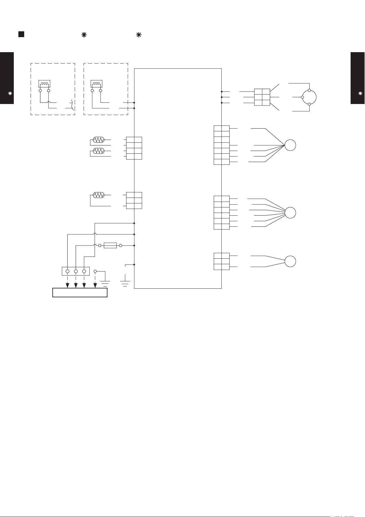
5. WIRING DIAGRAMS
MODEL : AS B09LD, AS B12LD, AS B18LD
FAN MOTOR
Indicator PCB Assy
AIR CLEAN UNIT
STEPPING
MOTOR
Controller PCB Assy
Power Relay
6
5
4
3
2
1
6
5
4
3
2
1
6
5
4
9
8
7
3
2
1
5
4
3
2
1
5
4
3
2
1
5
4
43
3
2
1
2
1
2
1
5
4
3
2
1
5
4
3
2
1
2
1
5
4
3
2
1
5
4
3
2
1
3
2
1
6
5
4
9
8
7
3
2
1
9
8
7
12
11
10
6
5
4
FM
M
TERMINAL
TO OUTDOOR UNIT
THERMAL FUSE
THERMISTOR
(PIPE TEMP.)
THERMISTOR
(ROOM TEMP.)
TEST
POWER
WHITE
TM1
CN201
CN101
TM2
W3
CN1 CN2 CN3 CN7 CN11
CN9CN4
CN10
WHITE
WHITE
WHITE
WHITE
WHITE
WHITE
WHITE
WHITE
WHITE
BLACK
RED
RED
BLUE
YELLOW
WHITE
WHITE
RED
RED
RED
BLUE
BLUE
BLACK or GRAY
BLACK or GRAY
BLACK
BLACK
GREEN
GREEN / YELLOW
BROWN
BLACK
RED
BLUE
PINK
YELLOW
YELLOW
ORANGE
WHITE
RED
BLUE
YELLOW
L
L 3N
N
SWITCH
102 C
Page 10
- (01 - 09) -
WALL MOUNTED TYPE
AS B09-18LD
WALL MOUNTED TYPE
AS B09-18LD
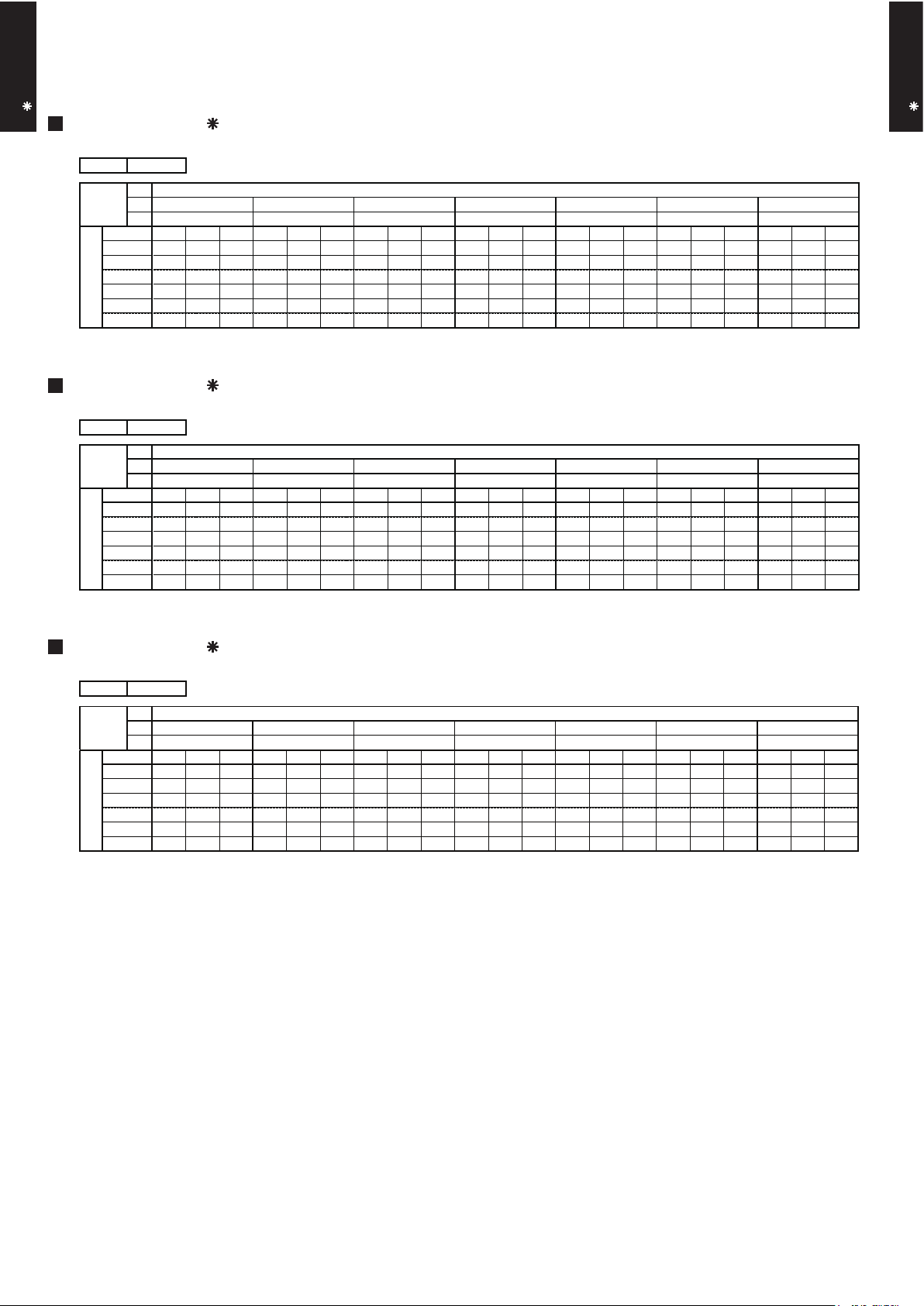
6. CAPACITY TABLE
6-1. COOLING CAPACITY
MODEL : AS B18LD
AFR : Air Flow Rate (m3/min)
TC : Total Capacity (kW)
SHC : Sensible Heat Capacity (kW)
PI : Power Input (kW)
°CDB
°CWB
TC SHC PI TC SHC PI TC SHC PI TC SHC PI TC SHC PI TC SHC PI TC SHC PI
3.85 2.61 0.82 4.29 2.63 0.83 4.44 2.86 0.84 4.73 2.86 0.84 4.87 3.09 0.85 5.17 3.08 0.86 5.46 3.28 0.87
4.59 3.11 1.36 5.11 3.13 1.38 5.29 3.40 1.39 5.63 3.41 1.40 5.81 3.69 1.41 6.16 3.67 1.43 6.51 3.91 1.44
4.39 2.98 1.51 4.89 3.00 1.53 5.06 3.26 1.54 5.39 3.27 1.56 5.56 3.53 1.56 5.89 3.51 1.58 6.23 3.74 1.59
4.11 2.79 1.66 4.58 2.80 1.69 4.73 3.05 1.69 5.04 3.06 1.71 5.20 3.30 1.72 5.51 3.29 1.74 5.82 3.50 1.75
3.71 2.51 1.67 4.13 2.53 1.70 4.27 2.75 1.70 4.55 2.76 1.72 4.69 2.98 1.73 4.98 2.97 1.75 5.26 3.16 1.77
3.47 2.35 1.68 3.86 2.36 1.71 3.99 2.57 1.72 4.26 2.58 1.74 4.39 2.78 1.75 4.65 2.77 1.76 4.91 2.95 1.78
AFR
11.7
43
25
30
35
40
Indoor temperature
Outdoor temperature
12
15
°CDB
20
232518
21
16
18
272932
231921
MODEL : AS B09LD
MODEL : AS B12LD
°CDB
°CWB
TC SHC PI TC SHC PI TC SHC PI TC SHC PI TC SHC PI TC SHC PI TC SHC PI
1.93 1.34 0.29 2.14 1.35 0.30 2.22 1.47 0.30 2.36 1.48 0.30 2.44 1.59 0.30 2.58 1.59 0.30 2.73 1.69 0.31
2.29 1.60 0.48 2.56 1.61 0.49 2.64 1.75 0.49 2.82 1.76 0.50 2.90 1.90 0.50 3.08 1.89 0.51 3.25 2.01 0.51
2.20 1.53 0.54 2.45 1.54 0.54 2.53 1.68 0.55 2.70 1.68 0.55 2.78 1.82 0.55 2.95 1.81 0.56 3.11 1.93 0.57
2.05 1.43 0.59 2.29 1.44 0.60 2.37 1.57 0.60 2.52 1.57 0.61 2.60 1.70 0.61 2.76 1.69 0.62 2.91 1.80 0.62
1.85 1.30 0.59 2.07 1.30 0.60 2.14 1.42 0.60 2.28 1.42 0.61 2.35 1.53 0.61 2.49 1.53 0.62 2.63 1.63 0.63
1.73 1.21 0.60 1.93 1.22 0.61 2.00 1.32 0.61 2.13 1.33 0.62 2.19 1.43 0.62 2.33 1.43 0.63 2.46 1.52 0.63
AFR
9.3
43
25
30
35
40
Indoor temperature
Outdoor temperature
12
15
°CDB
20
232518
21
16
18
272932
231921
°CDB
°CWB
TC SHC PI TC SHC PI TC SHC PI TC SHC PI TC SHC PI TC SHC PI TC SHC PI
2.59 1.82 0.43 2.89 1.83 0.44 2.99 1.99 0.44 3.18 2.00 0.45 3.28 2.16 0.45 3.48 2.15 0.45 3.67 2.29 0.46
3.09 2.17 0.72 3.44 2.18 0.73 3.56 2.37 0.74 3.79 2.38 0.74 3.91 2.57 0.75 4.14 2.56 0.75 4.38 2.73 0.76
2.96 2.08 0.80 3.29 2.09 0.81 3.41 2.27 0.81 3.63 2.28 0.82 3.74 2.46 0.83 3.97 2.45 0.84 4.19 2.61 0.84
2.77 1.94 0.88 3.08 1.95 0.89 3.19 2.12 0.90 3.40 2.13 0.91 3.50 2.30 0.91 3.71 2.29 0.92 3.92 2.44 0.93
2.50 1.75 0.88 2.78 1.76 0.90 2.87 1.92 0.90 3.06 1.92 0.91 3.16 2.08 0.92 3.35 2.07 0.92 3.54 2.20 0.93
2.33 1.64 0.89 2.60 1.65 0.91 2.69 1.79 0.91 2.86 1.80 0.92 2.95 1.94 0.92 3.13 1.93 0.93 3.31 2.06 0.94
16
18
272932
231921
232518
21
20
12
15
°CDB
AFR
9.9
43
25
30
35
40
Indoor temperature
Outdoor temperature
Page 11
- (01 - 10) -
WALL MOUNTED TYPE
AS B09-18LD
WALL MOUNTED TYPE
AS B09-18LD
6-2. HEATING CAPACITY
MODEL : AS B18LD
AFR: Air Flow Rate (m3/min)
TC : Total Capacity (kW)
PI : Power Input (kW)
TC PI TC PI TC PI TC PI TC PI
5.09 2.01 4.97 2.05 4.84 2.09 4.72 2.13 4.60 2.17
6.04 2.19 5.90 2.24 5.75 2.29 5.61 2.33 5.46 2.38
6.80 2.31 6.64 2.35 6.48 2.40 6.32 2.45 6.15 2.50
7.86 2.46 7.67 2.51 7.48 2.57 7.30 2.62 7.11 2.67
8.94 2.63 8.72 2.69 8.51 2.74 8.30 2.80 8.09 2.85
9.56 2.55 9.33 2.61 9.10 2.66 8.87 2.71 8.65 2.77
9.90 2.56 9.66 2.61 9.43 2.66 9.19 2.72 8.96 2.77
9.58 2.22 9.35 2.27 9.13 2.31 8.90 2.36 8.67 2.41
AFR
°CDB
11.7
-16
-11
-7
Outdoor temperature
15
10
6
0
-2
7
385
10
°CDB
°CWB
-15
24
-10
Indoor temperature
-5
161820
22
MODEL : AS B09LD
MODEL : AS B12LD
TC PI TC PI TC PI TC PI TC PI
3.41 1.48 3.33 1.51 3.25 1.54 3.17 1.57 3.09 1.60
4.05 1.62 3.95 1.65 3.86 1.68 3.76 1.72 3.66 1.75
4.56 1.70 4.45 1.74 4.34 1.77 4.23 1.81 4.12 1.84
5.27 1.82 5.14 1.85 5.02 1.89 4.89 1.93 4.77 1.97
5.99 1.94 5.85 1.98 5.71 2.02 5.56 2.06 5.42 2.10
6.41 1.88 6.25 1.92 6.10 1.96 5.95 2.00 5.80 2.04
6.63 1.88 6.48 1.92 6.32 1.96 6.16 2.00 6.00 2.04
6.42 1.64 6.27 1.67 6.12 1.71 5.96 1.74 5.81 1.77
AFR
°CDB
10.1
-16
-11
-7
Outdoor temperature
15
10
6
0
-2
7
385
10
°CDB
°CWB
-15
24
-10
Indoor temperature
-5
161820
22
TC PI TC PI TC PI TC PI TC PI
3.75 1.73 3.66 1.77 3.57 1.81 3.48 1.84 3.39 1.88
4.45 1.90 4.34 1.94 4.24 1.98 4.13 2.02 4.02 2.06
5.01 1.99 4.89 2.04 4.77 2.08 4.65 2.12 4.53 2.16
5.79 2.13 5.65 2.17 5.51 2.22 5.37 2.26 5.23 2.31
6.58 2.27 6.42 2.32 6.27 2.37 6.11 2.42 5.95 2.46
7.04 2.21 6.87 2.25 6.70 2.30 6.53 2.35 6.37 2.39
7.29 2.21 7.11 2.26 6.94 2.30 6.77 2.35 6.59 2.39
7.06 1.92 6.89 1.96 6.72 2.00 6.55 2.04 6.38 2.08
-10
Indoor temperature
-5
161820
22
°CDB
°CWB
-15
24
0
-2
7
385
10
15
10
6
AFR
°CDB
10.5
-16
-11
-7
Outdoor temperature
Page 12

- (01 - 11) -
WALL MOUNTED TYPE
AS B09-18LD
WALL MOUNTED TYPE
AS B09-18LD
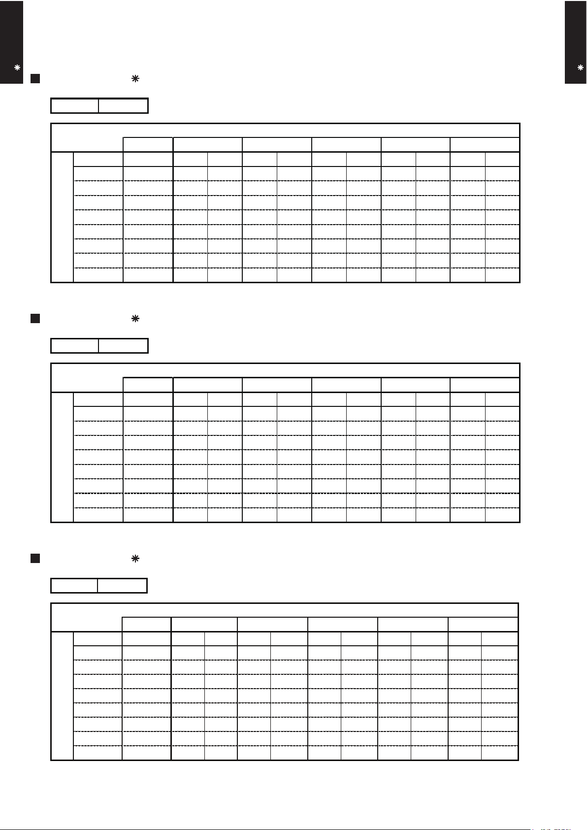
7. FAN PERFORMANCE
7-1. AIR VELOCITY DISTRIBUTION
MODEL : AS B09LD
Note :
Fan speed : High
Voltage : 230V
Unit : m/s
Unit : m/s
Unit : m/s
Unit : m/s
TOP VIEW
FLOW CONTROL PANEL : Horiz.
LOUVER : Center
TOP VIEW
FLOW CONTROL PANEL : Horiz.
LOUVER : Right & Left
SIDE VIEW
FLOW CONTROL PANEL : Horiz.
LOUVER : Center
SIDE VIEW
FLOW CONTROL PANEL : Vert.
LOUVER : Center
(m)
(m)
(m)
(m)
(m)
(m)
(m)
(m)
Operation mode :FAN
1
765
43
2 8
1 765432 8
3
2
1
0
1
2
3
2
1
0
1
2
0
1
2
3
1
765
43
2 8
0
1
2
3
1
765
43
2 8
2.0
1.0
0.5
0.5
1.0
1.0
2.0
2.0
0.5
2.0
1.0
0.5
2.0
1.0
0.5
Page 13

- (01 - 12) -
WALL MOUNTED TYPE
AS B09-18LD
WALL MOUNTED TYPE
AS B09-18LD
MODEL : AS B12LD
Note :
Fan speed : High
Voltage : 230V
Unit : m/s
Unit : m/s
Unit : m/s
Unit : m/s
TOP VIEW
FLOW CONTROL PANEL : Horiz.
LOUVER : Center
TOP VIEW
FLOW CONTROL PANEL : Horiz.
LOUVER : Right & Left
SIDE VIEW
FLOW CONTROL PANEL : Horiz.
LOUVER : Center
SIDE VIEW
FLOW CONTROL PANEL : Vert.
LOUVER : Center
(m)
(m)
(m)
(m)
(m)
(m)
(m)
(m)
Operation mode :FAN
1
765
43
2 8
1 765432 8
0
1
2
3
0
1
2
0
1
2
3
1
765
43
2 8
0
1
2
3
1
765
43
2 8
2.0
1.0
0.5
0.5
1.0
1.0
2.0
2.0
0.5
2.0
1.0
0.5
2.0
1.0
0.5
3
2
1
2
1
Page 14

- (01 - 13) -
WALL MOUNTED TYPE
AS B09-18LD
WALL MOUNTED TYPE
AS B09-18LD
MODEL : AS B18LD
Note :
Fan speed : High
Voltage : 230V
Unit : m/s
Unit : m/s
Unit : m/s
Unit : m/s
TOP VIEW
FLOW CONTROL PANEL : Horiz.
LOUVER : Center
TOP VIEW
FLOW CONTROL PANEL : Horiz.
LOUVER : Right & Left
SIDE VIEW
FLOW CONTROL PANEL : Horiz.
LOUVER : Center
SIDE VIEW
FLOW CONTROL PANEL : Vert.
LOUVER : Center
(m)
(m)
(m)
(m)
(m)
(m)
(m)
(m)
Operation mode :FAN
1
765
43
2 8
1 765432 8
0
1
2
3
0
1
2
0
1
2
3
1
765
43
2 8
0
1
2
3
1
765
43
2 8
2.0
1.0
0.5
0.5
0.5
1.0
1.0
2.0
2.0
2.0
1.0 0.5
2.0
1.0
0.5
3
2
1
2
1
Page 15

- (01 - 14) -
WALL MOUNTED TYPE
AS B09-18LD
WALL MOUNTED TYPE
AS B09-18LD
MODEL : AS B09LD
COOLING
7-2. AIR FLOW
HEATING
560
m3/h
156 l/s
330 CFM
470
m3/h
131 l/s
277 CFM
385
m3/h
107 l/s
227 CFM
260
m3/h
72 l/s
153 CFM
Airflow
Fan speed
Number of
rotations
(r.p.m)
Number of
rotations
(r.p.m)
HIGH
MED
LOW
QUIET
1300
1120
950
700
605
m3/h
168 l/s
356 CFM
510
m3/h
142 l/s
300 CFM
410
m3/h
114 l/s
241 CFM
290
m3/h
81 l/s
171 CFM
Airflow
HIGH
1390
MED
1200
LOW
1000
Fan speed
QUIET
760
Page 16

- (01 - 15) -
WALL MOUNTED TYPE
AS B09-18LD
WALL MOUNTED TYPE
AS B09-18LD
MODEL : AS B12LD
COOLING
HEATING
595
m3/h
165 l/s
350 CFM
485
m3/h
135 l/s
285 CFM
385
m3/h
107 l/s
227 CFM
260
m3/h
72 l/s
153 CFM
Airflow
HIGH
1370
Fan speed
1150
MED
LOW
950
QUIET
700
630
m3/h
175 l/s
371 CFM
510
m3/h
142 l/s
300 CFM
410
m3/h
114 l/s
241 CFM
290
m3/h
81 l/s
171 CFM
Airflow
Fan speed
HIGH
1440
1200
MED
LOW
QUIET
1000
760
Number of
rotations
(r.p.m)
Number of
rotations
(r.p.m)
Page 17

- (01 - 16) -
WALL MOUNTED TYPE
AS B09-18LD
WALL MOUNTED TYPE
AS B09-18LD
MODEL : AS B18LD
COOLING
HEATING
700
m3/h
194 l/s
412 CFM
580
m3/h
161 l/s
341 CFM
460
m3/h
128 l/s
271 CFM
370
m3/h
103 l/s
218 CFM
1560
1320
1090
850
HIGH
MED
LOW
QUIET
Airflow
Fan speed
Number of
rotations
(r.p.m)
700
m3/h
194 l/s
412 CFM
600
m3/h
167 l/s
353 CFM
500
m3/h
139 l/s
294 CFM
420
m3/h
117 l/s
247 CFM
1560
1370
1170
950
HIGH
MED
LOW
QUIET
Airflow
Fan speed
Number of
rotations
(r.p.m)
Page 18

- (01 - 17) -
WALL MOUNTED TYPE
AS B09-18LD
WALL MOUNTED TYPE
AS B09-18LD
8-1. NOISE LEVEL CURVE
8. OPERATION NOISE
COOLING
Octave band sound pressure level, dB:(0dB=0.0002µbar)
Octave band center frequency,Hz
0
10
20
30
40
50
60
70
80
Octave band sound pressure level, dB:(0dB=0.0002µbar)
0
10
20
30
40
50
60
70
80
63 125 250 500 1,000 2,000 4,000 8,000
Octave band center frequency,Hz
63 125 250 500 1,000 2,000 4,000 8,000
COOLING
Octave band sound pressure level, dB:(0dB=0.0002µbar)
Octave band center frequency,Hz
0
10
20
30
40
50
60
70
80
63 125 250 500 1,000 2,000 4,000 8,000
HEATING
Octave band sound pressure level, dB:(0dB=0.0002µbar)
Octave band center frequency,Hz
0
10
20
30
40
50
60
70
80
63 125 250 500 1,000 2,000 4,000 8,000
HEATING
High
Quiet
High
Quiet
High
Quiet
High
Quiet
MODEL : AS B09LD
MODEL : AS B12 LD
NC-20
NC-40
NC-50
NC-60
NC-30
NC-15
NC-25
NC-35
NC-45
NC-55
NC-65
NC-20
NC-40
NC-50
NC-60
NC-30
NC-15
NC-25
NC-35
NC-45
NC-55
NC-65
NC-20
NC-40
NC-50
NC-60
NC-30
NC-15
NC-25
NC-35
NC-45
NC-55
NC-65
NC-20
NC-40
NC-50
NC-60
NC-30
NC-15
NC-25
NC-35
NC-45
NC-55
NC-65
Page 19

- (01 - 18) -
WALL MOUNTED TYPE
AS B09-18LD
WALL MOUNTED TYPE
AS B09-18LD
COOLING
HEATING
MODEL : AS B18LD
Octave band sound pressure level, dB:(0dB=0.0002µbar)
Octave band center frequency,Hz
0
10
20
30
40
50
60
70
80
63 125 250 500 1,000 2,000 4,000 8,000
High
Quiet
NC-20
NC-40
NC-50
NC-60
NC-30
NC-15
NC-25
NC-35
NC-45
NC-55
NC-65
Octave band sound pressure level, dB:(0dB=0.0002µbar)
Octave band center frequency,Hz
0
10
20
30
40
50
60
70
80
63 125 250 500 1,000 2,000 4,000 8,000
High
Quiet
NC-20
NC-40
NC-50
NC-60
NC-30
NC-15
NC-25
NC-35
NC-45
NC-55
NC-65
Page 20
- (01 - 19) -
WALL MOUNTED TYPE
AS B09-18LD
WALL MOUNTED TYPE
AS B09-18LD
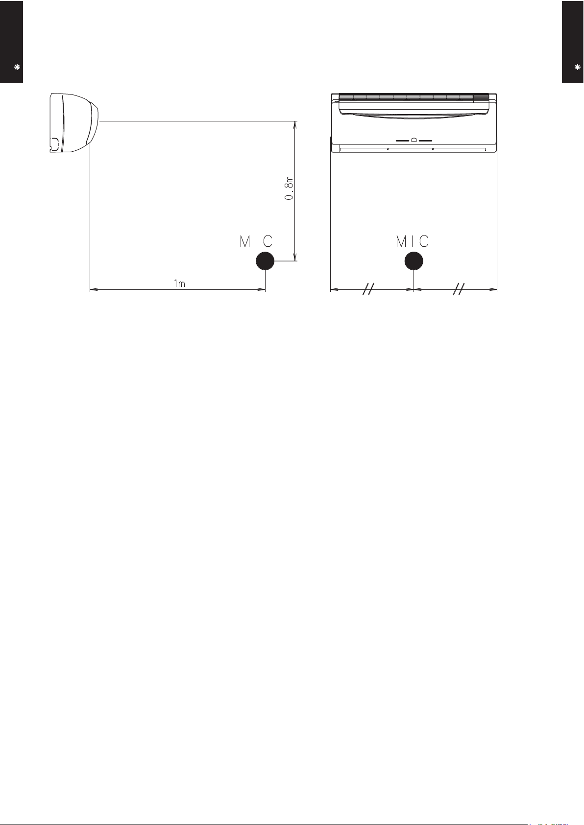
8-2.
SOUND LEVEL CHECK POINT
Page 21
- (01 - 20) -
WALL MOUNTED TYPE
AS B09-18LD
WALL MOUNTED TYPE
AS B09-18LD
9. ELECTRIC CHARACTERISTICS
AS B09LD AS B12LD AS B18LD
Voltage V
Frequency Hz
A 8.5 10.0 13.5
A 3.8 5.6
Circuit breaker A 15.0 20.0 20.0
Connection Cable
mm
2
1.5 - 2.5 1.5 - 2.5 2.0 - 3.5
Limited wiring length m 21 21 21
*1) Wiring Spec.
Selected Sample
(Selected based on Japan Electrotechnical Standard and Codes Committee E0005)
230
50
Model Name
Max Operating Current
*1)Wiring Spec.
Power Supply
Starting current
7.7
Page 22

- (01 - 21) -
WALL MOUNTED TYPE
AS B09-18LD
WALL MOUNTED TYPE
AS B09-18LD
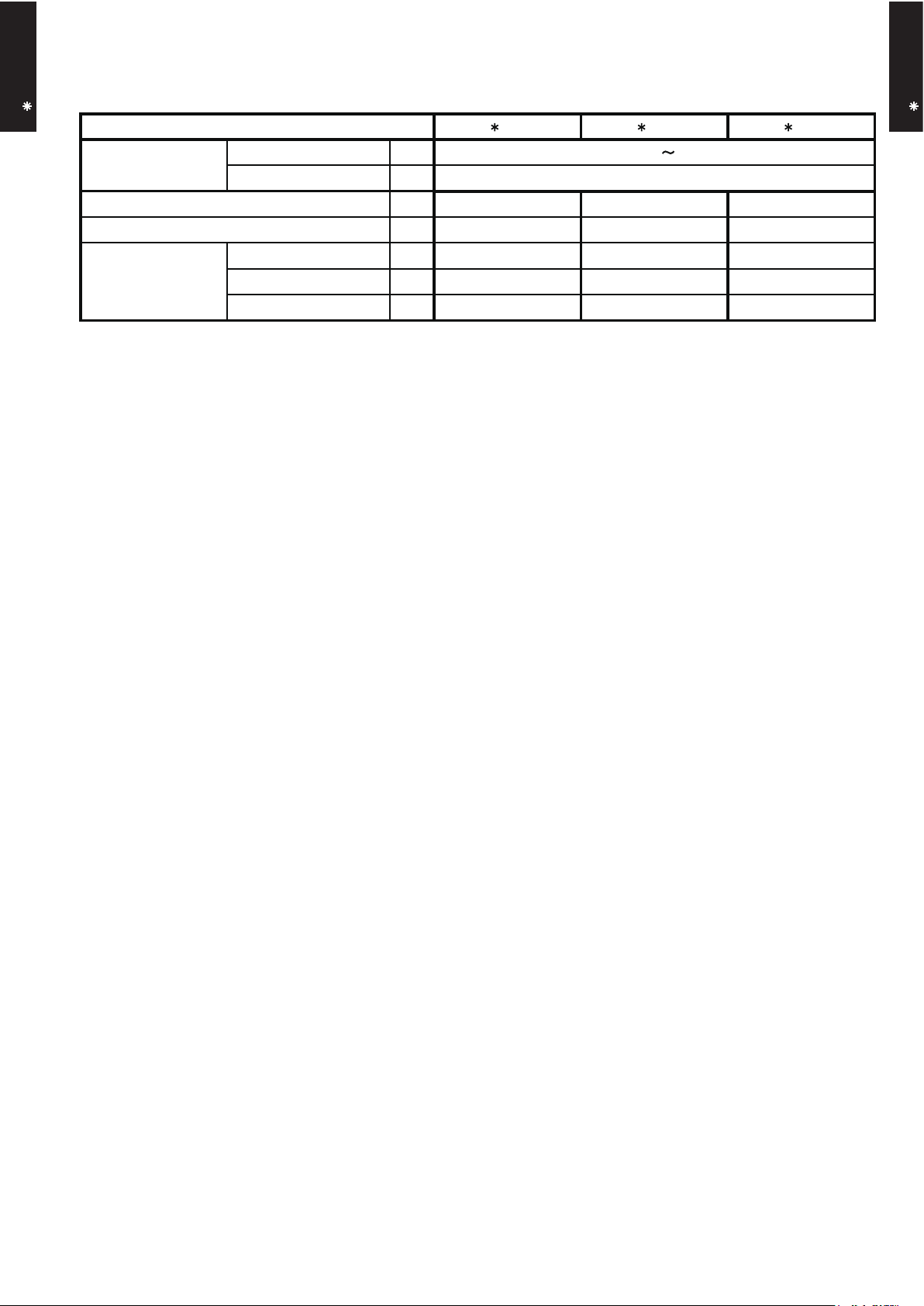
10. SAFETY DEVICES
AS B09LD AS B12LD AS B18LD
Circuit protection Current fuse (PCB)
Terminal protection Current (thermal) fuse
Fan motor protection Thermal protection program
3A 250V 102°C
100
+15
-10
°C OFF
95
+5
-10
°C ON
Protection form
Model
3.15A 250V
Page 23

- (01 - 22) -
WALL MOUNTED TYPE
AS B09-18LD
WALL MOUNTED TYPE
AS B09-18LD
11. OPTIONAL PARTS
Exterior Summary
Parts name
Air-cleaning and
deodorizing filter
Model No.
UTR-FA14
Negatively-charged dust, etc.
are attracted to the earth
section and are collected by a
bacteria eliminating &
deodorizing filter.
Page 24

R410A
D1D_AO012E/02
2007.11.26
AO S09LDC
AO S12LDC
AO S18LDC
2. SINGLE
TYPE :
OUTDOOR UNIT
Page 25

- (02 - 01) -
OUTDOOR UNIT
AO S09-18LD
OUTDOOR UNIT
AO S09-18LD
1. SPECIFICATIONS
AO S09LDC AO S12LDC
A 3.8 5.6
1,970 1,830
1,820 1,830
W
47 47
48 49
508 × 852 × 22 504 × 850 × 36.4
1.3 1.4
1 × 20 2 × 24
W
g 950 1,050
34 (75) 36 (79)
38 (84) 40 (88)
Note :
Specifications are based on the following conditions.
Cooling : Indoor temperature of 27°CDB/19°CWB. and outdoor temperature of 35°CDB/24°CWB.
Heating : Indoor temperature of 20°CDB/15°CWB. and outdoor temperature of 7°CDB/6°CWB.
Pipe length : 7.5 m, Height difference : 0 m. (Outdoor unit - Indoor unit)
Connection pipe
Size
mm
Refrigerant oil
Enclosure
Compressor
Refrigerant
Type × Q'ty
Motor output
Type
Charge
kg (lb.)
Dimensions
(H × W × D)
°C
Operation range
mm
Weight
Gross
Net
Gross
Liquid
Fan
Airflow
rate
Type
Model name
Heating
Type × Q'ty
m3/h
dB(A)
mm
230V 50Hz
198 - 264V 50Hz
Propeller fan × 1
Power source
Available voltage range
Starting current
Cooling
INVERTER HEAT PUMP
Copper
Aluminium
Rotary × 1
54
750
R410A
POE (VG74)
Steel
Beige
540 × 790 × 290
648 × 910 × 380
15
-10 to 43
-15 to 24
6.35 ( 1/4 in.)
9.52 ( 3/8 in.)
Flare
20 (chargeless : 15)
Motor output
Cooling
Heating
Dimensions (H × W × D)
Sound pressure level
Heat exchanger type
Fin pitch
Rows × Stages
Pipe type
Fin type
Type
Material
Colour
Net
Cooling
Heating
Gas
Method
Max. length
Max. height difference
m
Page 26

- (02 - 02) -
OUTDOOR UNIT
AO S09-18LD
OUTDOOR UNIT
AO S09-18LD
INVERTER HEAT PUMP
AO S18LDC
230V 50Hz
198 - 264V 50Hz
A 7.7
2,000
1,910
Propeller fan × 1
W 30
50
50
546 × 876 × 36.4
1.3
2 × 26
Copper
Aluminium
Rotary × 1
W 1,100
R410A
g 1,150
POE(VG74)
Steel
Beige
578 × 790 × 300
648 × 910 × 380
40 (88)
44 (97)
6.35 ( 1/4 in.)
12.7 ( 1/2 in.)
Flare
20(chargeless:15)
15
-10 to 43
-15 to 24
Note :
Specifications are based on the following conditions.
Cooling : Indoor temperature of 27°CDB/19°CWB. and outdoor temperature of 35°CDB/24°CWB.
Heating : Indoor temperature of 20°CDB/15°CWB. and outdoor temperature of 7°CDB/6°CWB.
Pipe length : 7.5 m, Height difference : 0 m. (Outdoor unit - Indoor unit)
Cooling
Heating
Colour
Net
Gross
Net
Type
Charge
Type
Material
Motor output
Cooling
Heating
Dimensions (H × W × D)
Type
Model name
Power source
Available voltage range
m
Connection pipe
Size
mm
Liquid
Gas
Method
Max. length
Max. height difference
Compressor
Refrigerant
Sound pressure level
Starting current
Cooling
Heating
Type × Q'ty
Refrigerant oil
Enclosure
Heat exchanger type
Fin pitch
Rows × Stages
Pipe type
Fin type
Type × Q'ty
Motor output
mm
Weight
kg(lb.)
Dimensions
(H × W × D)
Gross
°C
Operation range
Fan
Airflow
rate
m3/h
dB(A)
mm
Page 27

- (02 - 03) -
OUTDOOR UNIT
AO S09-18LD
OUTDOOR UNIT
AO S09-18LD
MODEL : AO S09LD, AO S12LD
(Unit : mm)
Top view
600 mm or more
100 mm or more
200 mm or more
100 mm or more
250 mm or more
(Service space)
INSTALLATION PLACE
Front view
Side view
If the space is larger that is stated, the condition will be the same as that are no obstacles.
540
320
540
790
56
290
353
17
2. DIMENSIONS
Page 28

- (02 - 04) -
OUTDOOR UNIT
AO S09-18LD
OUTDOOR UNIT
AO S09-18LD
MODEL : AO S18LD
(Unit : mm)
Air flow
Top view
Front view
Side view
Bottom view
600 mm or more
100 mm or more
300 mm or more
100 mm or more
300 mm or more
(Service space)
INSTALLATION PLACE
If the space is larger that is stated, the condition will be the same as that are no obstacles.
578
10
300
60
790
Page 29
- (02 - 05) -
OUTDOOR UNIT
AO S09-18LD
OUTDOOR UNIT
AO S09-18LD
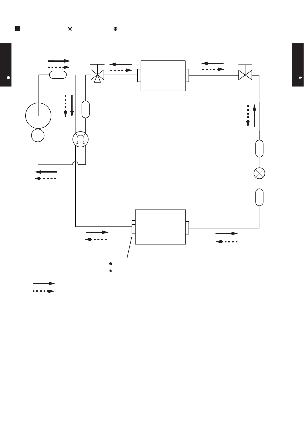
MODEL : AO S09LD, AO S12LD
3. REFRIGERANT CIRCUIT
2-Way
valve
Strainer
Strainer
3-Way
valve
Muffler
Muffler
4-Way valve
Expansion valve
Heat exchanger
( INDOOR )
Heat exchanger
( OUTDOOR )
AO S09LDC : 2 pass
AO S12LDC : 4 pass
Compressor
Cooling
Heating
Refrigerant pipe diameter
Liquid : 1/4" (6.35 mm)
Gas : 3/8" (9.52 mm)
Page 30

- (02 - 06) -
OUTDOOR UNIT
AO S09-18LD
OUTDOOR UNIT
AO S09-18LD
2-Way
valve
Strainer
Strainer
Sub-heat
exchanger
( INDOOR )
3-Way
valve
Muffler
4-Way valve
Expansion valve
Heat exchanger
( INDOOR )
Heat exchanger
( OUTDOOR )
Sub-accumulator
Compressor
Cooling
Heating
Refrigerant pipe diameter
Liquid : 1/4" (6.35 mm)
Gas : 1/2" (12.7 mm)
MODEL : AO S18LD
Page 31
- (02 - 07) -
OUTDOOR UNIT
AO S09-18LD
OUTDOOR UNIT
AO S09-18LD
MODEL : AO S09LD, AO S12LD
4. WIRING DIAGRAMS
TO INDOOR UNIT
PCB (MAIN)
REACTOR
THERMISTOR (PIPE)
THERMISTOR (DISCHARGE PIPE)
THERMISTOR (OUTDOOR TEMP.)
COMPRESSOR
C(W)
S(V)
R(U)
FUSE 250V20A
4 W V
P W V
F M
C M
TERMINAL
4-WAY
VALVE
EXPANSION
VALVE
FAN
MOTOR
REACTOR
6
5
4
7
3
2
1
6
5
4
7
3
2
1
3
2
1
3
2
1
4
3
2
1
4
3
2
1
6
5
4
3
2
1
6
5
4
3
2
1
3
2
1
3
2
1
3
2
1
3
2
1
RED
OR
W10
W11
CN71
CN70
W4
W2
W1
W3
CN30
CN40
CN80 0
W7
W8
W9
WHITE
RED
WHITE
BLACK
BLACK
BLACK
BLACK
RED
WHITE
GREEN
BLACK
BLACK
BLACK
RED
RED
RED
RED
BROWN
BLUE
BLUE
ORANGE
YELLOW
YELLOW
WHITE
WHITE
BLACK
BLACK
WHITE
WHITE
BLACK BLACK
BROWN
BROWN
3LN
Page 32

- (02 - 08) -
OUTDOOR UNIT
AO S09-18LD
OUTDOOR UNIT
AO S09-18LD
MODEL : AO S18LD
TO INDOOR UNIT
RED
WHITE
BLACK
RED
BLACK
WHITE
YELLOW
BLUE
RED
WHITE
BLACK
BLACK
BLACK
RED
BROWN
BLUE
ORANGE
YELLOW
WHITE
BLACK
BLACK
WHITE
RED
BLACK
BLACK
BLACK
BLACK
BROWN
BROWN
WHITE
YELLOW
RED
YELLOW
CN71
CN70
CN40
CN800
CN30
GREEN
W4
W2
W1
W3
W10
W11
W7
W8
W9
1
2
3
4
5
6
7
1
2
1
2
3
4
5
6
7
1
2
3
4
5
6
1
2
3
4
5
6
1
2
3
4
1
2
3
4
1
2
3
1
2
3
1
2
3
1
2
3
1
2
3
1
2
3
2
1
TERMINAL
N
L 3
FUSE
250V-20A
PIPE TEMP. THERMISTOR
DISCHARGE TEMP. THERMISTOR
OUTDOOR TEMP. THERMISTOR
REACTOR
COMPRESSOR
FAN MOTOR
EXPANSION VALVE
4-WAY VALVE
C M
F M
PMV
4WV
R(R)
S(S)
C(T)
CONTROLLER PCB ASSY
Page 33

- (02 - 09) -
OUTDOOR UNIT
AO S09-18LD
OUTDOOR UNIT
AO S09-18LD
5. COEFFICIENT OF COMPENSATION FOR PIPE LENGTH
AND HEIGHT DIFFERENCE
MODEL : AO S09LD, AO S12LD, AO S18LD
Indoor unit
Height difference H
Connection pipe
H
Outdoor unit
Indoor unit
Connection pipe
H
Outdoor unit
Indoor unit is upper than outdoor unit.1 Indoor unit is under than outdoor unit.2
5 7.5 10 15 20
15 - - - 0.953 0.950
10 - - 0.983 0.968 0.966
7.5 - 0.988 0.987 0.972 0.970
5 0.992 0.992 0.991 0.976 0.974
0 1.000 1.000 0.999 0.984 0.982
-5 1.000 1.000 0.999 0.984 0.982
-7.5 - 1.000 0.999 0.984 0.982
-10 - - 0.999 0.984 0.982
-15 - - - 0.984 0.982
5 7.5 10 15 20
15 - - - 0.920 0.894
10 - - 0.982 0.920 0.894
7.5 - 1.000 0.982 0.920 0.894
5 0.993 1.000 0.982 0.920 0.894
0 0.993 1.000 0.982 0.920 0.894
-5 0.988 0.995 0.977 0.916 0.889
-7.5 - 0.993 0.975 0.913 0.887
-10 - - 0.972 0.911 0.885
-15 - - - 0.902 0.876
COOLING
Pipe length (m)
Height
difference H
(m)
1
Indoor unit is upper
than outdoor unit.
2
Indoor unit is under
than outdoor unit
HEATING
Pipe length (m)
Height
difference H
(m)
1
Indoor unit is upper
than outdoor unit.
2
Indoor unit is under
than outdoor unit
Page 34

- (02 - 10) -
OUTDOOR UNIT
AO S09-18LD
OUTDOOR UNIT
AO S09-18LD
6. ADDITIONAL CHARGE CALCULATION
MODEL : AO S09LD
REFRIGERANT CHARGE
MODEL : AO S12LD
REFRIGERANT CHARGE
Refrigerant amount g
Pipe length m 15 20
Additional charge g 0 (Chargeless) +100
Refrigerant amount g
Pipe length m 15 20
Additional charge g 0 (Chargeless) +100
20g/m
R410A
950
Refrigerant type
Refrigerant type
R410A
20g/m
1,050
MODEL : AO S18LD
REFRIGERANT CHARGE
Refrigerant amount g
Pipe length m
Additional charge g
Refrigerant type
15 20
0 (Chargeless) +100
R410A
20g/m
1150
Page 35

- (02 - 11) -
OUTDOOR UNIT
AO S09-18LD
OUTDOOR UNIT
AO S09-18LD
MODEL : AO S09LD
7. AIR FLOW
COOLING
HEATING
1970
m3/h
547 l/s
1159 CFM
1820
m3/h
506 l/s
1071 CFM
1830
m3/h
508 l/s
1077 CFM
1830
m3/h
508 l/s
1077 CFM
Number of
rotations
(r.p.m)
820
760
Airflow
Airflow
Airflow
Airflow
Number of
rotations
(r.p.m)
820
820
MODEL : AO S12LD
COOLING
HEATING
Number of
rotations
(r.p.m)
Number of
rotations
(r.p.m)
Page 36

- (02 - 12) -
OUTDOOR UNIT
AO S09-18LD
OUTDOOR UNIT
AO S09-18LD
MODEL : AO S18LD
COOLING
HEATING
2000
m3/h
556 l/s
1177 CFM
1910
m3/h
531 l/s
1124 CFM
820
Airflow
Airflow
Number of rotations
(r.p.m)
Number of rotations
(r.p.m)
860
Page 37

- (02 - 13) -
OUTDOOR UNIT
AO S09-18LD
OUTDOOR UNIT
AO S09-18LD
8-1. NOISE LEVEL CURVE
8. OPERATION NOISE
COOLING
Octave band sound pressure level, dB:(0dB=0.0002µbar)
Octave band center frequency,Hz
0
10
20
30
40
50
60
70
80
Octave band sound pressure level, dB:(0dB=0.0002µbar)
0
10
20
30
40
50
60
70
80
63 125 250 500 1,000 2,000 4,000 8,000
Octave band center frequency,Hz
63 125 250 500 1,000 2,000 4,000 8,000
COOLING
Octave band sound pressure level, dB:(0dB=0.0002µbar)
Octave band center frequency,Hz
0
10
20
30
40
50
60
70
80
63 125 250 500 1,000 2,000 4,000 8,000
HEATING
Octave band sound pressure level, dB:(0dB=0.0002µbar)
Octave band center frequency,Hz
0
10
20
30
40
50
60
70
80
63 125 250 500 1,000 2,000 4,000 8,000
HEATING
MODEL : AO S09LD
MODEL : AO S12LD
NC-20
NC-40
NC-50
NC-60
NC-30
NC-15
NC-25
NC-35
NC-45
NC-55
NC-65
NC-20
NC-40
NC-50
NC-60
NC-30
NC-15
NC-25
NC-35
NC-45
NC-55
NC-65
NC-20
NC-40
NC-50
NC-60
NC-30
NC-15
NC-25
NC-35
NC-45
NC-55
NC-65
NC-20
NC-40
NC-50
NC-60
NC-30
NC-15
NC-25
NC-35
NC-45
NC-55
NC-65
Page 38

- (02 - 14) -
OUTDOOR UNIT
AO S09-18LD
OUTDOOR UNIT
AO S09-18LD
COOLING
HEATING
MODEL : AO S18LD
Octave band sound pressure level, dB:(0dB=0.0002µbar)
Octave band center frequency,Hz
0
10
20
30
40
50
60
70
80
63 125 250 500 1,000 2,000 4,000 8,000
Octave band sound pressure level, dB:(0dB=0.0002µbar)
Octave band center frequency,Hz
0
10
20
30
40
50
60
70
80
63 125 250 500 1,000 2,000 4,000 8,000
NC-20
NC-40
NC-50
NC-60
NC-30
NC-15
NC-25
NC-35
NC-45
NC-55
NC-65
NC-20
NC-40
NC-50
NC-60
NC-30
NC-15
NC-25
NC-35
NC-45
NC-55
NC-65
Page 39

- (02 - 15) -
OUTDOOR UNIT
AO S09-18LD
OUTDOOR UNIT
AO S09-18LD
8-2. SOUND LEVEL CHECK POINT
Page 40

- (02 - 16) -
OUTDOOR UNIT
AO S09-18LD
OUTDOOR UNIT
AO S09-18LD
9. ELECTRIC CHARACTERISTICS
AO S09LD AO S12LD AO S18LD
Voltage V
Frequency Hz
A 3.8 5.6 7.7
Model Name
Starting Current
Power Supply
50
230
Page 41

- (02 - 17) -
OUTDOOR UNIT
AO S09-18LD
OUTDOOR UNIT
AO S09-18LD
10. SAFETY DEVICES
AO S09LD AO S12LD AO S18LD
Current fuse
(NEAR THE TERMINAL)
Fan motor protection Thermal protection program
OFF : 100
+15
-10
°C
ON : 95
+15
-10
°C
Compressor protection
Thermal protection program
(DISCHARGE TEMP.)
OFF : 110°C
ON : After 7 minutes
Model
20A 250V
15A 250V
3.15A 250V
OFF : 135
+5
-5
°C
ON : 95
+15
-15
°C
Protection form
Circuit protection
Current fuse
(MAIN PRINTED CIRCUIT BOARD)
 Loading...