

Page 1

DESIGN & TECHNICAL MANUAL
INDOOR
OUTDOOR
AOG45LETL
ABG45LRTA
AIR CONDITIONER
Ceiling type
Page 2

1. INDOOR UNIT
DTR_AB038E_04
2016.11.07
CEILING TYPE :
ABG45LRTA
Page 3

- (3) -
CEILING TYPE
AB
G4 5LR TA
CEILING TYPE
AB
G4 5LR TA
CONTENTS
1. INDOOR UNIT
1. FEATURES
........................................................................................................ 01 - 01
2. WIRELESS REMOTE CONTROLLER
......................................... 01 - 03
3. SPECIFICATIONS
........................................................................................ 01 - 05
4. DIMENSIONS
................................................................................................... 01 - 06
5. WIRING DIAGRAMS
.................................................................................. 01 - 08
6. CAPACITY TABLE
....................................................................................... 01 - 09
6-1. COOLING CAPACITY
................................................................................ 01 - 09
6-2. HEATING CAPACITY
................................................................................. 01 - 10
7. FAN PERFORMANCE
...............................................................................01 - 11
7-1. AIR VELOCITY DISTRIBUTION
................................................................01 - 11
7-2. AIRFLOW
..................................................................................................... 01 - 12
7-3. FRESH AIR CHARACTERISTIC
.............................................................. 01 - 13
8. OPERATION NOISE
................................................................................... 01 - 14
8-1. NOISE LEVEL CURVE
............................................................................... 01 - 14
8-2. SOUND LEVEL CHECK POINT
............................................................... 01 - 15
9. ELECTRIC CHARACTERISTICS
..................................................... 01 - 16
10. SAFETY DEVICES
....................................................................................... 01 - 17
11. EXTERNAL INPUT & OUTPUT
......................................................... 01 - 18
11-1. EXTERNAL INPUT
...................................................................................... 01 - 18
11-2. EXTERNAL OUTPUT
................................................................................. 01 - 19
12. FUNCTION SETTINGS
............................................................................. 01 - 21
12-1. INDOOR UNIT
.............................................................................................. 01 - 21
12-2. INDOOR UNIT (Setting by remote controller)
..................................... 01 - 22
13. OPTIONAL PARTS
...................................................................................... 01 - 27
13-1. CONTROLLER
............................................................................................ 01 - 27
13-2. OTHERS
....................................................................................................... 01 - 28
Page 4

- (01 - 01) -
CEILING TYPE
AB
G4 5LR TA
CEILING TYPE
AB
G4 5LR TA
FEATURES1.
MODEL
ABG45LRTE / AOG45LETL
FEATURES
Energy saving
z
High energy saving was realized by making the indoor unit and outdoor unit fan motor and
compressor all DC and optimal design of the refrigerant cycle.
Quiet operation
z
Air ow mode can be set in 4 steps and more detailed air ow setting is possible.
45 type: 34 dB at operation in the Quiet mode.
Filter sign
z
Dirtying of lter is detected by air conditioner operating time and the user is informed.
Economy operation
z
The power consumption can be reduced.
Wired/wireless simultaneous use possible
z
Wired remote controller and wireless remote controller can be simultaneously used.
Flexible installation
z
A high installation of the
construction of the ceiling
and degree of freedom
corresponding to height is
possible.
Double auto swing
z
Combination of up/down and right/left air direction swing allows three-dimensional air direction
control.
Since up/down air direction aps operate automatically, according to the operating mode of the
unit, it is possible to set the air direction based on the operating mode.
(Field Supplied)
Open Concealed Wall mounted
5 steps selectable
1
2
5
4
3
1
2
5
4
3
Steps
Swing: Cooling, Dry and Fan mode
Swing: Heating and Fan mode
5 steps selectable
Up and Down SwingRight and Left Swing
Page 5

- (01 - 02) -
CEILING TYPE
AB
G4 5LR TA
CEILING TYPE
AB
G4 5LR TA
Fresh-air intake
z
OUTDOOR
Fresh-air
INDOOR
Page 6
- (01 - 03) -
CEILING TYPE
AB
G4 5LR TA
CEILING TYPE
AB
G4 5LR TA
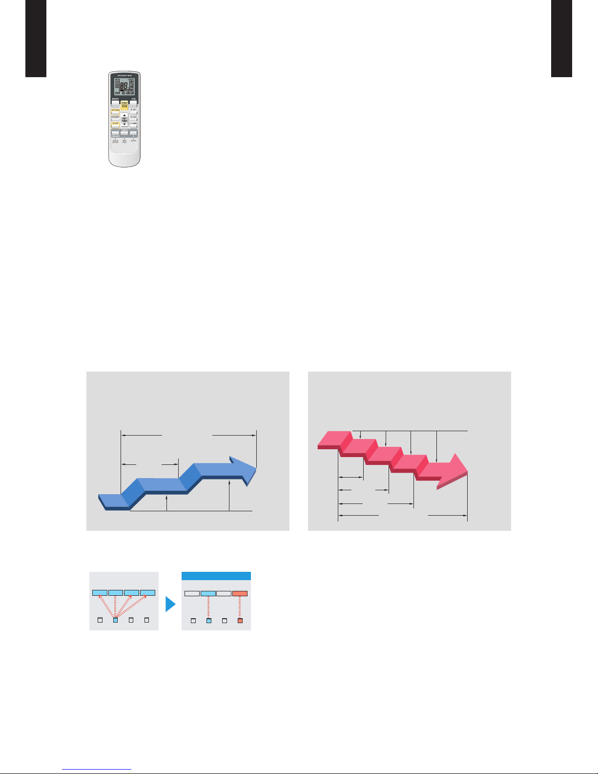
WIRELESS REMOTE CONTROLLER2.
FEATURES
4 mode timer setup available (ON / OFF / PROGRAM / SLEEP).
Easy operation.
Easy to change custom code (max. 4 units) by button operation.
Simple function setting
z
Setting of the air conditioner selection function is performed by remote controller.
Built-in timers
z
Select from four different timer programs (ON / OFF / PROGRAM / SLEEP).
Program timer
z
The program timer operates the on and off timer once within a 24 hour period.
Sleep timer
z
The sleep timer function automatically corrects the temperature thermostat setting according to
the time setting to prevent excessive cooling and heating while sleeping.
Switching remote controller custom code
z
A B C D
A B
C
D
Mixed-up
I.U. I.U. I.U. I.U.
I.U. I.U. I.U. I.U.
After code change
Code selector switch eliminates unit
•
being wrongly switched.
(Up to 4 codes can be set.)
*I.U.=Indoor unit
60min.
1 °C
2 °C
Timer setting
Cooling operation/dry operation
When the sleep timer is set, the set temperature
automatically rises 1°C every hour. The set
temperature can rise up to a maximum of 2°C.
1 °C
30min.
60min.
90min.
2 °C
3 °C
4 °C
Timer setting
Heating operation
When the sleep timer is set, the set temperature
automatically drops 1°C every 30 minutes. The set
temperature can drop to a maximum of 4°C.
Page 7

- (01 - 04) -
CEILING TYPE
AB
G4 5LR TA
CEILING TYPE
AB
G4 5LR TA
FUNCTIONS
Note: Functions will be different due to type of indoor unit.
For details, please see operation manual.
SPECIFICATION
SIZE (H × W × D mm) 170 × 56 × 19
WEIGHT (g) 85 (w/o batteries)
ACCESSORY Holder
Display panel
2
4
9
3
1
16
15
5
10
13
11
12
14
8
7
6
17
18
19
21
24
23
22
20
MODE button1
Selects the operating mode (AUTO, COOL, DRY, FAN, HEAT).
/Start / end R.C. custom code change. (Max 4 types)
10°C2
HEAT button
SET TEMP. button ( ▲ / ▼ )3
Sets the indoor temp./ Sets R.C. custom code.
ECONOMY button4
SLEEP button5
Pressed to select sleep timer.
FAN button6
Selects the fan speed (AUTO, HIGH, MED, LOW, QUIET).
START/STOP button7
Pressed to start and stop operation.
SET button (Vertical)8
Air ow direction vertical set button.
SET button (Horizontal)9
Air ow direction horizontal set button.
SWING button10
Air ow direction swing button.
TIMER MODE button11
Pressed to select the timer mode. (OFF TIMER, ON TIMER,
PROGRAM TIMER, TIMER RESET)
TIMER SET ( 12
/
) button
Sets the current time and on-off time.
CLOCK ADJUST button13
Sets the current time.
RESET button14
Used when replacing batteries.
TEST RUN button15
Used when testing the air conditioner after installation.
Signal transmitter16
Temperature set display17
Operating mode display18
Sleep display19
Transmit indicator20
Fan speed display21
Swing display22
Timer mode display23
Clock display24
Page 8

- (01 - 05) -
CEILING TYPE
AB
G4 5LR TA
CEILING TYPE
AB
G4 5LR TA
SPECIFICATIONS3.
Note :
Speci cations are base d on the foll owing conditio ns.
Coolin g : Indoor te mperat ure of 27˚CD B / 19˚CWB.a nd outdoo r temperature of 35˚C DB / 24˚CWB.
Heating : I ndoor te mperatu re of 20˚CD B / 15˚CWB.and o utdoor te mperatu re of 7˚CD B / 6˚CWB.
Pipe leng th : 5 m, Heig ht diffe rence : 0 m.(O utdoor un it - Indoo r unit)
The prote ctive fu nction m ight work w hen using outside t he opera tion ran ge.
*The ma ximum cu rrent is th e maximum value whe n operate d with in th e operat ion rang e.
Type
CEILING MODEL
INVERTER HEATPUMP
Model name AB
G45LRTA
Power source 230 V ~ 50 Hz
Available voltage range 198 - 264 V
Capacity
Cooling
Rated
kW 12.1
BTU/h 41300
Min-Max
kW 4.0-13.3
BTU/h 13700-45400
Heating
Rated
kW 13.3
BTU/h 45400
Min-Max
kW 4.2-15.5
BTU/h 14300-52900
Input power
Cooling
Rated
kW
3.77
Max 4.70
Heating
Rated 3.68
Max 4.70
Current
Cooling
Rated A
16.5
Heating 16.1
EER Cooling
kW/kW
3.21
COP Heating 3.61
Moisture removal l/h (pints/h) 4.0(7.0)
Maximum operating current *
Cooling
A
20.5
Heating 20.5
Fan
Airow
rate
Cooling
High
m3/h
2100
Med 1700
Low 1400
Quiet 1100
Heating
High 2100
Med 1700
Low 1400
Quiet 1100
Type × Q'ty Sirocco× 4
Motor output W 130
Sound pressure level
Cooling
High
dB(A)
49
Med 45
Low 39
Quiet 34
Heating
High 49
Med 45
Low 39
Quiet 34
Heat exchanger type
Dimensions (H × W × D)
mm
252x1350x39.9
Fin pitch 1.45
Rows x Stages 3 x 12
Pipe type Copper
Fin type Aluminium
Enclosure
Material ABS
Colour
WHITE
( Approximate colour of MUNSELL N 9.25 / )
Dimensions
( H×W×D)
Net
mm
240×1660×700
Gross 318×1800×795
Weight
Net
kg
46
Gross 58
Connection pipe
Size
Liquid
mm
Ø9.52 (3/8 in.)
Gas Ø15.88 (5/8 in.)
Method Flare
Operation range
Cooling
˚C 18 to 32
%RH 80 or less
Heating ˚C 16 to 30
Remote controller type Wireless
Drain port
Material ABS
Size mm Ø 21.5 (I.D.), Ø26.0 (O.D.)
Page 9
- (01 - 06) -
CEILING TYPE
AB
G4 5LR TA
CEILING TYPE
AB
G4 5LR TA
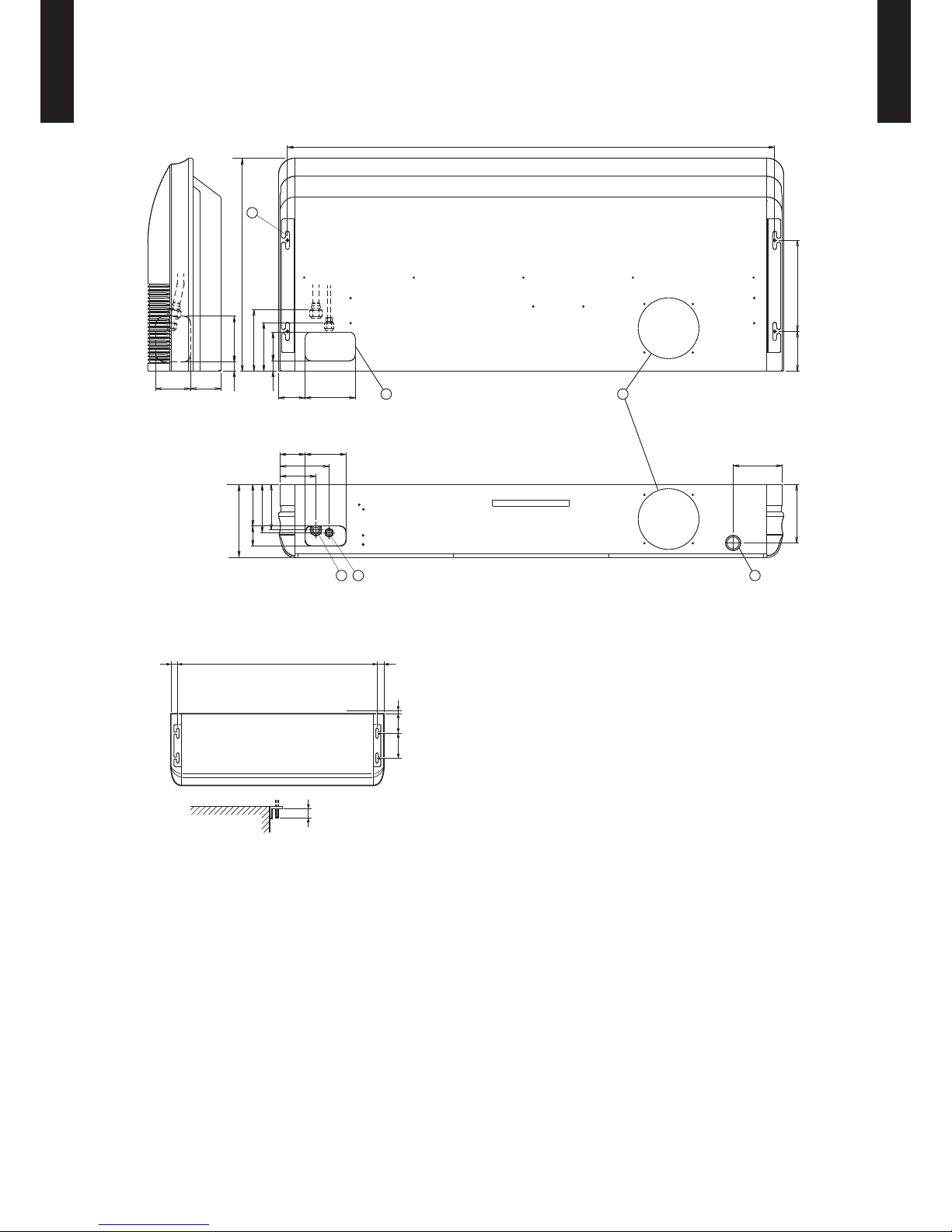
DIMENSIONS4.
MODEL : ABG45LRTA
(Unit : mm)
Refrigerant piping are connection (Gas)
Refrigerant piping are connection (Liquid)
Drain piping connection
Knock out hole for fresh air
Knock out hole for refrigerant piping
Hole for lifting bolt (Use M10 screw bolt)
Top view
Side view
Rear view
1 2 3
45
6
3030
Suspension bolt pitch
1,600
INDOOR UNIT (Top view)
Dimensions
(Space Required
for Installation)
10
155
300
INDOOR UNIT
Suspension bolt
should extend
outward 30 to 75.
160
1,600
88 165
13582
160
118
100115
300130
192
200
160
9533
240
137
160
150
65
15030
700
Page 10
- (01 - 07) -
CEILING TYPE
AB
G4 5LR TA
CEILING TYPE
AB
G4 5LR TA
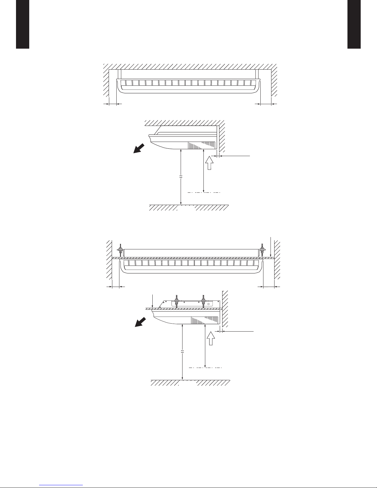
INSTALLATION PLACE
(Unit : mm)
Ceiling
150 or more80 or more
10 or more
2500 or more
1000 or more
INDOOR UNIT
Ceiling
Obstruction
Floor
INDOOR UNIT
Ceiling panel
Ceiling panel
150 or more80 or more
10 or more
2500 or more
1000 or more
Obstruction
Floor
Page 11
- (01 - 08) -
CEILING TYPE
AB
G4 5LR TA
CEILING TYPE
AB
G4 5LR TA
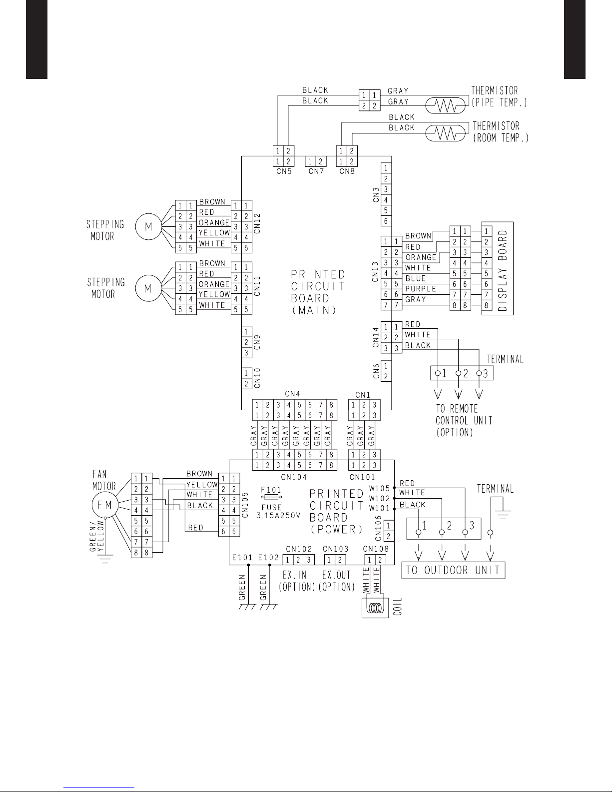
WIRING DIAGRAMS5.
MODEL : ABG45LRTA
Page 12

- (01 - 09) -
CEILING TYPE
AB
G4 5LR TA
CEILING TYPE
AB
G4 5LR TA
CAPACITY TABLE6.
COOLING CAPACITY6-1.
This table is created using the maximum capacity.
MODEL : ABG45LRTA / AOG45LETL
AFR : Air ow rate (m3/min)
TC : Total capaci ty (kW)
SHC : Sens ible Hea t capaci ty (kW)
IP : Input Pow er(kW)
AFR 35.0
Indoor temperature
°CDB 18 21 23 25 27 29 32
°CWB 12 15 16 18 19 21 23
Outdoor temperature
°CDB TC SHC IP TC SHC IP TC SHC IP TC SHC IP TC SHC IP TC SHC IP TC SHC IP
-15 11.08 8.53 2.62 12.35 8.58 2.66 12.77 9.32 2.67 13.61 9.35 2.70 14.03 10.10 2.71 14.87 10.06 2.74 15.71 10.72 2.76
-10 11.01 8.53 2.63 12.26 8.58 2.68 12.68 9.33 2.69 13.51 9.36 2.72 13.93 10.11 2.73 14.77 10.07 2.76 15.60 10.73 2.78
0 11.20 8.64 2.36 12.47 8.69 2.40 12.90 9.44 2.41 13.75 9.47 2.44 14.18 10.23 2.45 15.03 10.19 2.47 15.88 10.86 2.50
5 11.02 8.56 2.37 12.28 8.61 2.41 12.69 9.36 2.42 13.53 9.39 2.45 13.95 10.14 2.46 14.79 10.10 2.48 15.62 10.76 2.51
10 10.84 8.48 2.73 12.08 8.53 2.77 12.49 9.27 2.79 13.31 9.30 2.82 13.72 10.04 2.83 14.55 10.00 2.86 15.37 10.66 2.89
15 10.73 8.45 2.84 11.95 8.50 2.88 12.35 9.24 2.90 13.17 9.27 2.93 13.58 10.01 2.94 14.39 9.97 2.97 15.21 10.62 3.00
20 10.87 8.52 3.17 12.11 8.57 3.22 12.52 9.31 3.24 13.35 9.34 3.27 13.76 10.09 3.29 14.59 10.05 3.32 15.41 10.71 3.36
25 10.74 8.49 3.46 11.96 8.54 3.52 12.37 9.28 3.54 13.19 9.32 3.57 13.59 10.06 3.59 14.41 10.02 3.63 15.23 10.67 3.66
30 10.73 8.48 4.27 11.95 8.53 4.33 12.36 9.27 4.35 13.17 9.30 4.40 13.58 10.05 4.42 14.39 10.01 4.42 15.21 10.66 4.42
35 10.51 8.46 4.27 11.70 8.51 4.33 12.10 9.26 4.35 12.90 9.29 4.40 13.30 10.03 4.42 14.10 9.99 4.42 14.90 10.64 4.42
40 8.41 7.33 3.84 9.37 7.49 3.90 9.69 8.15 3.92 10.33 8.17 3.96 10.65 8.83 3.98 11.29 8.79 3.98 11.92 9.36 3.98
46 6.42 6.41 3.17 7.16 6.59 3.21 7.40 7.17 3.23 7.89 7.19 3.26 8.13 7.77 3.28 8.62 7.73 3.28 9.11 8.24 3.28
Page 13

- (01 - 10) -
CEILING TYPE
AB
G4 5LR TA
CEILING TYPE
AB
G4 5LR TA
HEATING CAPACITY6-2.
This table is created using the maximum capacity.
MODEL : ABG45LRTA / AOG45LETL
AFR : Air o w rate (m3/min)
TC : Total capaci ty (kW)
IP : Input Pow er(kW)
AFR 35.0
Indoor temperature
°CDB 16 18 20 22 24
Outdoor temperature
°CDB °CWB TC IP TC IP TC IP TC IP TC IP
-15 -16 10.71 4.21 10.46 4.30 10.20 4.39 9.95 4.48 9.69 4.57
-10 -11 11.68 4.23 11.41 4.32 11.13 4.41 10.85 4.50 10.57 4.59
-5 -7 12.67 4.25 12.37 4.34 12.06 4.43 11.76 4.43 11.46 4.43
0 -2 13.64 4.25 13.31 4.34 12.99 4.43 12.66 4.43 12.34 4.43
5 3 14.97 4.25 14.61 4.34 14.26 4.43 13.90 4.43 13.55 4.43
7 6 16.28 4.25 15.89 4.34 15.50 4.43 15.11 4.43 14.73 4.43
10 8 16.45 4.25 16.06 4.34 15.66 4.43 15.27 4.43 14.88 4.43
15 10 16.22 3.80 15.84 3.88 15.45 3.96 15.06 3.96 14.68 3.96
20 15 15.78 3.35 15.40 3.42 15.03 3.49 14.65 3.49 14.28 3.49
24 18 16.62 3.35 16.22 3.42 15.82 3.49 15.43 3.49 15.03 3.49
Page 14

- (01 - 11) -
CEILING TYPE
AB
G4 5LR TA
CEILING TYPE
AB
G4 5LR TA
FAN PERFORMANCE7.
AIR VELOCITY DISTRIBUTION7-1.
MODEL : ABG45LRTA
2 1 0.5 0.25
1
4
3
2
4
1
2
3
0
(m) Unit : m/s
Top view
Vertic al air ow direction lou ver: Up
Horizo ntal air ow direction l ouver: Ce nter
2
1
1
0.5
0.5
0.25
0.25
1
4
3
2
4
1
2
3
0
(m) Unit : m/s
Top view
Vertic al air ow direction lou ver: Up
Horizo ntal air ow direction l ouver: Ri ght and Lef t
2
1 0.5 0.25
2
3
1
(m) Unit : m/s
Side view
Vertic al air ow direction lou ver: Up
Horizo ntal air ow direction l ouver: Ce nter
2
1
0.5
0.25
2
3
1
0
(m) Unit : m/s
Side view
Vertic al air ow direction lou ver: Cente r
Horizo ntal air ow direction l ouver: Ce nter
2
1
0.5
0.25
2
3
1
0
(m) Unit : m/s
Side view
Vertic al air ow direction lou ver: Down
Horizo ntal air ow directio n louver: C enter
Note:
Condition
Fan speed : High
Operation mode : FAN
0 1 18
(m)
2 3 4 5 6 7 8 9 10 11 12 13 14 15 16 17
0 1
(m)
2 3 4 5 6 7 8 9 10 11 12 13 14
0 1
(m)
2 3 4 5 6 7 8 9 10 11 12 13 14
0 1 18
(m)
2 3 4 5 6 7 8 9 10 11 12 13 14 15 16 17
0 1 18
(m)
2 3 4 5 6 7 8 9 10 11 12 13 14 15 16 17
Page 15
- (01 - 12) -
CEILING TYPE
AB
G4 5LR TA
CEILING TYPE
AB
G4 5LR TA
AIRFLOW7-2.
MODEL : ABG45LRTA
Cooling
z
Heating
z
Fan speed
Number of
rotations
(r.p.m.)
Airow
HIGH 1200
m
3
/h 2100
l/s 583
CFM 1236
MED 1000
m
3
/h 1700
l/s 472
CFM 1000
LOW 830
m
3
/h 1400
l/s 389
CFM 824
QUIET 680
m
3
/h 1100
l/s 306
CFM 647
Fan speed
Number of
rotations
(r.p.m.)
Airow
HIGH 1200
m
3
/h 2100
l/s 583
CFM 1236
MED 1000
m
3
/h 1700
l/s 472
CFM 1000
LOW 830
m
3
/h 1400
l/s 389
CFM 824
QUIET 680
m
3
/h 1100
l/s 306
CFM 647
Page 16
- (01 - 13) -
CEILING TYPE
AB
G4 5LR TA
CEILING TYPE
AB
G4 5LR TA
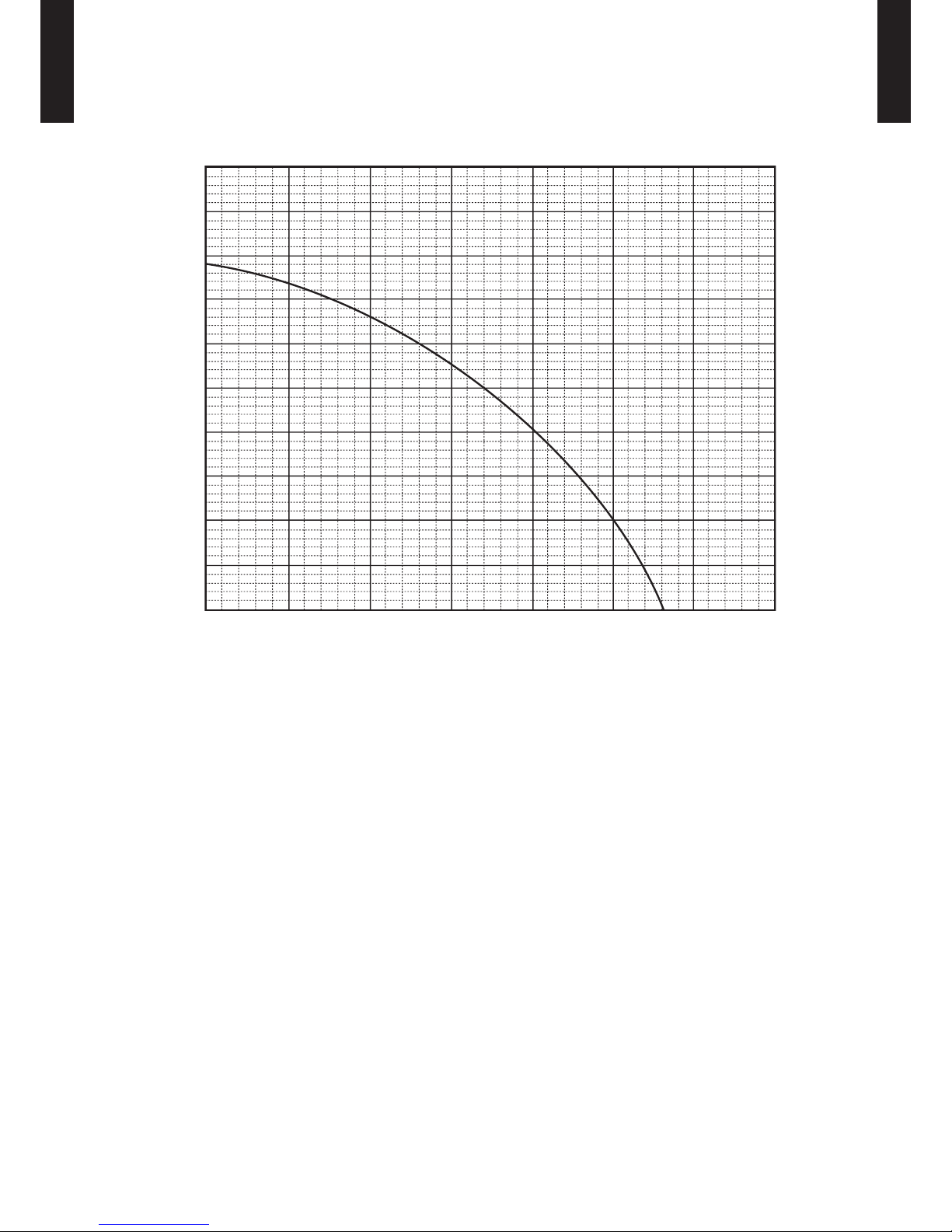
FRESH AIR CHARACTERISTIC7-3.
MODEL : ABG45LRTA
0 1 2 3 4 5 6 7
(mmA q)
0
2
4
6
8
(Pa) 98
0
49
Fresh air ow (m3/min)
Intake duct static pressure
10
Page 17
- (01 - 14) -
CEILING TYPE
AB
G4 5LR TA
CEILING TYPE
AB
G4 5LR TA
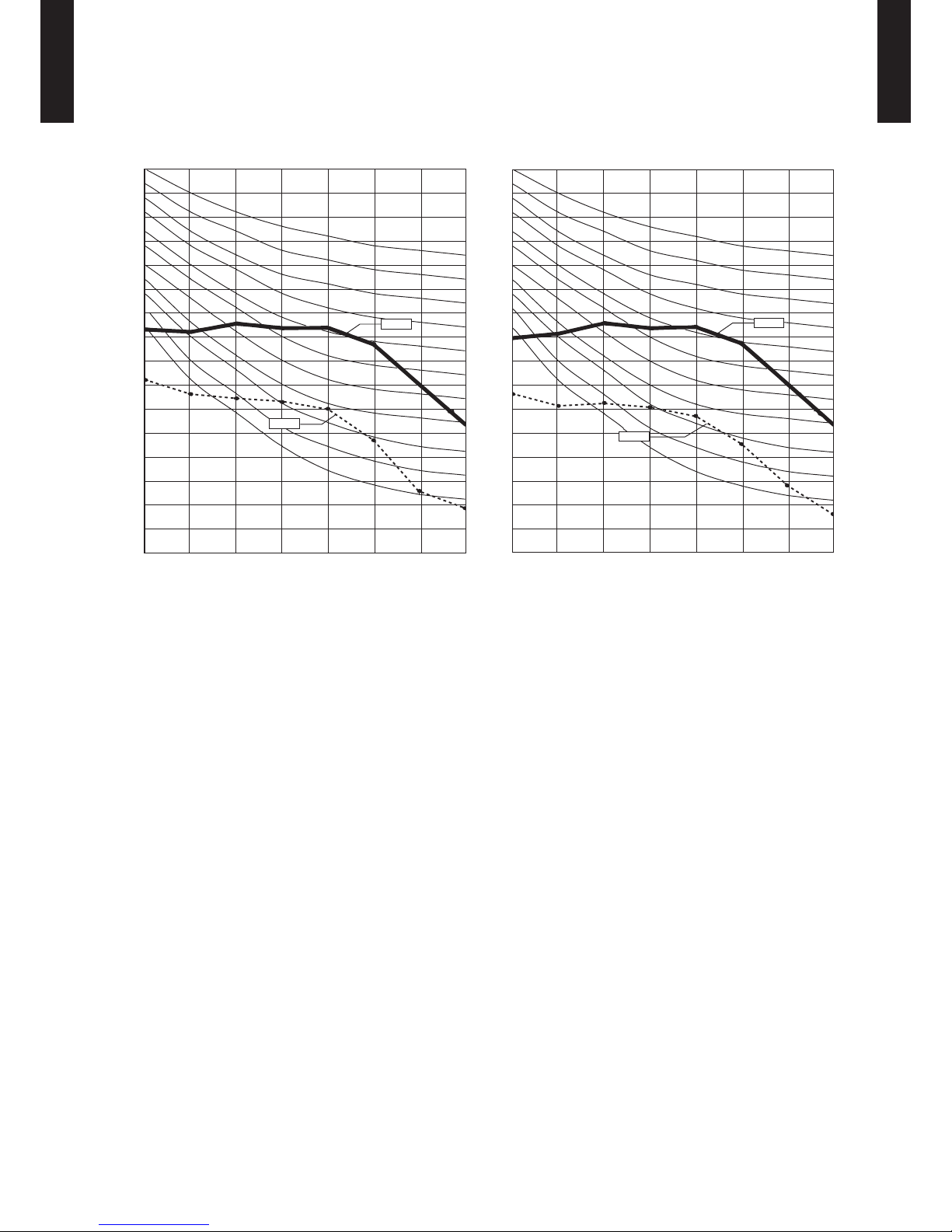
OPERATION NOISE8.
NOISE LEVEL CURVE8-1.
MODEL : ABG45LRTA
QUIET
HIGH
Heating
z
Octave ba nd sound p ressure level, dB:(0 dB= 0.00 02µbar)
Octave ba nd cente r frequ ency,Hz
80
70
60
50
40
30
20
10
0
63 125 250 500 1,000 2,000 4,00 0 8,00 0
NC-65
NC-60
NC-55
NC-50
NC-45
NC-40
NC-35
NC-30
NC-25
NC-20
NC -15
QUIET
HIGH
Cooling
z
Octave ba nd sound p ressure level, dB:(0 dB= 0.00 02µbar)
Octave ba nd cente r frequ ency,Hz
80
70
60
50
40
30
20
10
0
63 125 250 500 1,000 2,000 4,00 0 8,00 0
NC-65
NC-60
NC-55
NC-50
NC-45
NC-40
NC-35
NC-30
NC-25
NC-20
NC -15
Page 18

- (01 - 15) -
CEILING TYPE
AB
G4 5LR TA
CEILING TYPE
AB
G4 5LR TA
SOUND LEVEL CHECK POINT8-2.
Page 19

- (01 - 16) -
CEILING TYPE
AB
G4 5LR TA
CEILING TYPE
AB
G4 5LR TA
ELECTRIC CHARACTERISTICS9.
Model name ABG45LRTA
Power supply
Voltage V 230 ~
Frequency Hz 50
Max. operating current (Indoor unit) A 0.8
*1) Wiring spec.
(Indoor unit to
outdoor unit)
Connection cable mm
2
1.5 ~ 2.5
Limited wiring length m 50
*1) Wiring Spec.
Selected Sample
(Selected based on Japan Electrotechnical Standards and Codes Committee E0005)
Page 20

- (01 - 17) -
CEILING TYPE
AB
G4 5LR TA
CEILING TYPE
AB
G4 5LR TA
SAFETY DEVICES10.
Protection form
Model
ABG45LRTA
Circuit protection Current fuse (PCB) 250V 3.15A
Fan motor protection
Thermal protection
program
135±15°C OFF
115±15°C ON
Page 21

- (01 - 18) -
CEILING TYPE
AB
G4 5LR TA
CEILING TYPE
AB
G4 5LR TA
EXTERNAL INPUT & OUTPUT11.
Connector INPUT OUTPUT REMARKS
CN102 Control input —
See external
input/output settings for
details.
CN103 — Operation status output
CN6 — Fresh air control output
EXTERNAL INPUT11-1.
CONTROL INPUT (Operation/Stop or Forced stop)
The air conditioner can be remotely operated by means of the following on-site work.
"Operation/Stop" mode or "Forced stop" mode can be selected with function setting of indoor unit.
Unit operation is started at the following contents by adding the contact input of a commercial ON/OFF switch to a
connector on the external control PC board and turning it ON.
Unit operation Initial starting after turned power on Other than initial starting
Operation mode Auto changeover Mode at previous operation
Set temperature 24°C Temperature at previous operation
Air ow mode AUTO Mode at previous operation
Air direction (swing) Standard air direction (swing OFF) Air direction at previous operation
Circuit diagram example
z
Indoor unit
control PC board Connected unit
Ex.) Switch
Connector
1
3
Signal
Field supply
* Make the distance from the PC board to the connected unit within 10m.
*10 m
Contact capacity : 5VDC or more, 15mA or more.
Please use the non-polar relays and switches.
When function setting is "Operation/Stop" mode ●
Input signal
Indoor unit
Operation
Stop
ON
OFF
When function setting is "Forced stop" mode ●
ON ON ON
Remote control
operation invalidity
ON
OFF
Operation
Stop
Forced stop
Normal
Remote controller
Input signal
Indoor unit
Command
Parts (Optional)
z
Model name
UT Y-XWZ X
Wire (External input)
Page 22

- (01 - 19) -
CEILING TYPE
AB
G4 5LR TA
CEILING TYPE
AB
G4 5LR TA
EXTERNAL OUTPUT11-2.
OPERATION STATUS OUTPUT
An air conditioner operation status signal can be output.
Circuit diagram example
z
Field supply
Ex.)Display
Indoor
control PC board
Connected unit
Ex.)Relay unit
1
2
Signal
Relay
power
supply
V
Connector
* Make the distance from the PC board to the connected unit within 10m.
Relay spec. : Max.24VDC, 10mA to less than 500mA.
*10 m
24V DC
Indoor unit
Output signal
ON
OFF
Operation
Stop
Parts (Optional)
z
Model name
UT Y-XWZ X
Wire (External output)
Page 23

- (01 - 20) -
CEILING TYPE
AB
G4 5LR TA
CEILING TYPE
AB
G4 5LR TA
FRESH AIR CONTROL OUTPUT
A signal linked to air conditioner indoor fan ON can be output.
* However, signal becomes OFF during cold air prevention control operation.
Circuit diagram example
z
Field supply
Indoor
control PC board
Connector
1
12 V
on/off
2
Signal
Relay
power
supply
* Make the distance from the PC board to the connected unit within 10m.
Relay spec. : Rated 12VDC, 50mA or less.
Ex.) Fan
Connected unit
Ex.) Relay unit
*10 m
ON
OFF
Operation
Stop
Indoor fan
Output signal
Parts (Optional)
z
Model name
UTD-ECS5A
Wire (Fresh air output)
Page 24

- (01 - 21) -
CEILING TYPE
AB
G4 5LR TA
CEILING TYPE
AB
G4 5LR TA
FUNCTION SETTINGS12.
INDOOR UNIT12-1.
SWITCH POSITION
DIP-SW SETTING
Remote controller address setting
z
A number of indoor units can be operated at the same time using a wired remote controller.
Set the unit number of each indoor unit using the DIP switches on the indoor unit circuit board.
(See the following table.)
The DIP switches are normally set to make the unit number 00.
(. . .Factory setting)
Remote controller address
DIP switch No.
1 2 3 4
00 OFF OFF OFF OFF
01 ON OFF OFF OFF
02 OFF ON OFF OFF
03 ON ON OFF OFF
04 OFF OFF ON OFF
05 ON OFF ON OFF
06 OFF ON ON OFF
07 ON ON ON OFF
08 OFF OFF OFF ON
09 ON OFF OFF ON
10 OFF ON OFF ON
11 ON ON OFF ON
12 OFF OFF ON ON
13 ON OFF ON ON
14 OFF ON ON ON
15 ON ON ON ON
INDOOR UNIT
DIP SW
1
Remote controller address setting
2
3
4
Jumper Wire
JM1
Setting prohibitedJM2
JM3
JM3
JM2
JM1
Indoor unit Printed circuit board
MAIN PCB
Page 25

- (01 - 22) -
CEILING TYPE
AB
G4 5LR TA
CEILING TYPE
AB
G4 5LR TA
INDOOR UNIT (Setting by remote controller)12-2.
The function settings of the control of the indoor unit can be changed by this procedure according •
to the installation conditions. Incorrect settings can cause the indoor unit malfunction.
After the power is turned on, perform the “FUNCTION SETTING” according to the installation •
conditions using the remote controller.
The settings may be selected between the following two: Function Number or Setting Value. •
Settings will not be changed if invalid numbers or setting values are selected. •
PREPARATION
Turn on the power. •
* By turning on the power indoor units, so make sure the piping air-tight test and vacuuming have
been conducted before turning on the power.
* Also check again to make sure no wiring mistakes were made before turning on the power.
FUNCTION SETTING METHOD (for Wireless remote controller)
Entering the Function Setting Mode
While pressing the FAN button and SET TEMP. (
•
) simultaneously, press the RESET button to enter the function
setting mode.
STEP 1
Setting the Remote controller Custom code
Use the following steps to select the custom code of the remote controller. (Note that
the air conditioner cannot receive a signal if the air conditioner has not been set for
the matching costom code.) The custom codes that are set through this process are
applicable only to the signals in the FUNCTION SETTING. For details on how to set
the custom codes through the normal process, refer to REMOTE CONTROLLER
Custom code SETTING.
Press the SET TEMP. (1. ) ( ) button to change the custom code between →
→ → Match the code on the display to the air conditioner custom code. (initially
set to )
(If the custom code does not need to be selected, press the MODE button and
proceed to STEP 2.)
Press the TIMER MODE button and check that the indoor unit can receive signals 2.
at the displayed custom code.
Press the MODE button to accept the custom code, and proceed to STEP 2.3.
The air conditioner custom code is set to A prior to shipment.
The remote controller resets to custom code A when the batteries in the remote controller are replaced. If you use a
custom code other than custom code A, reset the custom code after replacing the batteries.
If you do not know the air conditioner custom code setting, try each of the custom codes ( → → → ) until
you nd the code which operates the air conditioner.
STEP 2
Selecting the Function Number and Setting Value
Press the SET TEMP. (1. ) ( ) buttons to select the function
numbe r.
(Press the MODE button to switch between the left and right
digits.)
Press the FAN button to proceed to setting the value. 2.
Press the FAN button again to return to the function number
selection.)
Press the SET TEMP. (3. ) ( ) buttons to select the setting value.
(Press the MODE button to switch between the left and right
digits.)
Press the TIMER MODE button, and START/STOP button, in the 4.
order listed to conrm the settings.
Press the RESET button to cancel the function setting mode.5.
After completing the FUNCTION SETTING, be sure to turn off 6.
the power and turn it on again.
Function number
Setting value
CAUTION
After turning off the power, wait 30 seconds or more before turning on it again.
The FUNCTION SETTING doesn’t become effective if it doesn’t do so.
Page 26

- (01 - 23) -
CEILING TYPE
AB
G4 5LR TA
CEILING TYPE
AB
G4 5LR TA
CONTENTS OF FUNCTION SETTING
Follow the instructions in the Local Setup Procedure, which is supplied with the remote control, in •
accordance with the installed condition.
After the power is turned on, perform the Function Setting on the remote control.
The settings may be selected between the following two: Function Number or Setting Value. •
Settings will not be changed if invalid numbers or setting values are selected. •
1) Filter sign
2) Ceiling height
3) Room temperature control for cooling
4) Room temperature control for heating
5) Auto restart
6) Room temperature sensor switching
7) Remote controller custom code
8) External input control
9) Room temperature sensor switching (Aux.)
10) Indoor unit fan control for energy saving for cooling
1) Filter sign
Select appropriate intervals for displaying the lter sign on the indoor unit according to the
estimated amount of dust in the air of the room.
If the indication is not required, select "No indication" (03).
(. . .Factory setting)
Setting Description Function Number Setting Value
"Standard
(2,500 hours)"
11
00
"Long interval
(4,400 hours)"
01
"Short interval
(1,250 hours)"
02
No indication 03
2) Ceiling height
Select the appropriate ceiling height according to the place of installation.
(. . .Factory setting)
Setting Description Function Number Setting Value
Standard
(2.5m to 3.0m)
20
00
High ceiling
(3.0m or more)
01
3) Room temperature control for cooling
Depending on the installed environment, correction of the room temperature sensor may be
required.
Select the appropriate control setting according to the installed environment..
(. . .Factory setting)
Setting Description Function Number Setting Value
Standard
30
00
Slightly lower control 01
Lower control 02
Higher control 03
Page 27

- (01 - 24) -
CEILING TYPE
AB
G4 5LR TA
CEILING TYPE
AB
G4 5LR TA
4) Room temperature control for heating
Depending on the installed environment, correction of the room temperature sensor may be
required.
Select the appropriate control setting according to the installed environment..
(. . .Factory setting)
Setting Description Function Number Setting Value
Standard
31
00
Lower control 01
Slightly higher control 02
Higher control 03
5) Auto restart
Enable or disable automatic restart after a power interruption.
(. . .Factory setting)
Setting Description Function Number Setting Value
Enable
40
00
Disable 01
* Auto restart is an emergency function such as for power outage etc.
Do not attempt to use this function in normal operation.
Be sure to operate the unit by remote controller or external device.
6) Room temperature sensor switching
(Only for wired remote controller)
When using the Wired remote controller temperature sensor, change the setting to "Both" (01).
(. . .Factory setting)
Setting Description Function Number Setting Value
Indoor unit
42
00
Both 01
00: Sensor on the indoor unit is active.
01: Sensors on both indoor unit and wired remote controller are active.
*Remote controller sensor must be turned on by using the remote controller.
7) Remote controller custom code
(Only for wireless remote controller)
The indoor unit custom code can be changed.
Select the appropriate custom code.
(. . .Factory setting)
Setting Description Function Number Setting Value
A
44
00
B 01
C 02
D 03
Page 28

- (01 - 25) -
CEILING TYPE
AB
G4 5LR TA
CEILING TYPE
AB
G4 5LR TA
8) External input control
"Operation/Stop" mode or "Forced stop" mode can be selected.
(. . .Factory setting)
Setting Description Function Number Setting Value
Operation/Stop mode
46
00
(Setting prohibited) 01
Forced stop mode 02
9) Room temperature sensor switching (Aux.)
To use the temperature sensor on the wired remote controller only, change the setting to "Wired
remote controller" (01).
This function will only work if the function setting 42 is set at "Both" (01).
(. . .Factory setting)
Setting Description Function Number Setting Value
Both
48
00
Wired remote controller 01
10) Indoor unit fan control for energy saving for cooling
Enables or disables the power-saving function by controlling the indoor unit fan rotation when the
outdoor unit is stopped during cooling operation.
(
. . .Factory setting)
Setting Description Function Number Setting Value
Disable
49
00
Enable 01
00: When the outdoor unit is stopped, the indoor unit fan operates continuously following the
setting on the remote controller.
01: When the outdoor unit is stopped, the indoor unit fan operates intermittently at a very low
speed.
Page 29

- (01 - 26) -
CEILING TYPE
AB
G4 5LR TA
CEILING TYPE
AB
G4 5LR TA
REMOTE CONTROLLER CUSTOM CODE SETTING
Use the following steps to select the custom code of the remote controller.
(Note that the air conditioner cannot receive a signal if the conditioner has not been set for the matching custom code.)
1. Press the START/STOP button until only the clock is displayed on the remote controller display.
2. Press the MODE button for at least ve seconds to display the current custom code (initially set to ).
3. Press the SET TEMP. ( ) ( ) button to change the custom code between → → → .
Match the code on the display to the air conditioner custom code.
4. Press the MODE button again to return to the clock display. The custom code will be changed.
If no buttons are pressed within 30 seconds after the custom code is displayed, the system returns to the original
clock display. In this case, start again from step 1.
The air conditioner custom code is set to A prior to shipment. Contact your retailer to change the custom code.
The remote controller resets to custom code A when the batteries in the remote controller are replaced. If you use a
custom code other than custom code A, reset the custom code after replacing the batteries.
If you do not know the air conditioner custom code setting,try each of the custom codes (
→ → → .) until you
nd the code which operates the air conditioner.
Page 30

- (01 - 27) -
CEILING TYPE
AB
G4 5LR TA
CEILING TYPE
AB
G4 5LR TA
OPTIONAL PARTS13.
CONTROLLER13-1.
Exterior Parts name Model No. Summary
Wired remote
controller
UTY- RVNM
Large and full-dot liquid
crystal screen, wide and
large keys easy to press,
user-intuitive arrow key.
Wired remote
controller
UTY-RNNM
Unit control is performed by
wired remote controller
Simple remote
controller
UTY-RSNM
Unit control is performed by
simple remote controller.
Page 31

- (01 - 28) -
CEILING TYPE
AB
G4 5LR TA
CEILING TYPE
AB
G4 5LR TA
OTHERS13-2.
Exterior Parts name Model No. Summary
Drain pump
unit
UTR-DPB24T
Optional drain lift-up
mechanism allows more
exible installation.
Round ange UTD-RF204
Round ange is used when
the fresh air duct is installed.
Round an ge
External
connect kit
UTY-XWZX
Use to connect with various
peripheral devices and air
conditioner PC board.
( x 1 ) ( x 2 )
( x 1 ) ( x 2 )
External
control set
UTD-ECS5A
Use to connect with various
peripheral devices and air
conditioner PC board.
(Set of 6)
Page 32

DTR_AO136E_04
2016.04.22
SINGLE TYPE :
AOG45LETL
AOG54LETL
2. OUTDOOR UNIT
Page 33

OUTDOOR UNIT
AO
G45-54LETL
OUTDOOR UNIT
AO
G45-54LETL
2. OUTDOOR UNIT
CONTENTS
1. FEATURE
······························································································ 02 - 01
2. SPECIFICATIONS
·············································································· 02 - 03
3. DIMENSIONS
······················································································· 02 - 04
4. INSTALLATION PLACE
··································································· 02 - 05
4-1. SINGLE OUTDOOR UNIT INSTALLATION
········································· 02 - 05
4-2. MULTIPLE OUTDOOR UNIT INSTALLATION
····································· 02 - 06
4-3. OUTDOOR UNIT INSTALLATION IN MULTI ROW
····························· 02 - 06
5. REFRIGERANT CIRCUIT
······························································· 02 - 07
6. WIRING DIAGRAMS
········································································· 02 - 08
7. CAPACITY COMPENSATION RATE FOR PIPE LENGTH
AND HEIGHT DIFFERENCE
························································· 02 - 09
8. ADDITIONAL CHARGE CALCULATION
·································· 02 - 11
9. AIR FLOW
····························································································· 02 - 12
10. OPERATION NOISE (SOUND PRESSURE)
··························· 02 - 13
10-1. NOISE LEVEL CURVE
········································································· 02 - 13
10-2. SOUND LEVEL CHECK POINT
··························································· 02 - 14
11. ELECTRIC CHARACTERISTICS
················································· 02 - 15
12. SAFETY DEVICES
············································································ 02 - 16
13. EXTERNAL INPUT & OUTPUT
···················································· 02 - 17
13-1. EXTERNAL INPUT
··············································································· 02 - 17
13-2. EXTERNAL OUTPUT
··········································································· 02 - 19
14. FUNCTION SETTINGS
···································································· 02 - 21
14-1. FIELD SETTING SWITCHES
······························································· 02 - 21
14-2. SETTING METHOD
·············································································· 02 - 22
14-2-1. LOW NOISE MODE
········································································· 02 - 22
14-2-2. PEAK CUT MODE
··········································································· 02 - 23
15. OPTIONAL PARTS
············································································ 02 - 24
Page 34

- (02 - 01) -
OUTDOOR UNIT
AO
G45-54LETL
OUTDOOR UNIT
AO
G45-54LETL
FEATURE1.
FEATURES
Peak cut operation
z
Peak cut mode
Suppresses maximum capacity to perform energy-saving operation, preventing breaker tripping.
This function operates by setting a peak current value and reducing the power consumption.
* Performance drops by reducing the power consumption preferentially.
Level 1 ... Suppresses the power consumption to almost 0% by stopping the compressor.
Level 2 ... Suppresses the power consumption to 50% of the rated power consumption value.
Level 3 ... Suppresses the power consumption to 75% of the rated power consumption value.
Level 4 ... Suppresses the power consumption to the rated power consumption value (100%).
W
Capacity
Time
Setting level
Peak cut
Control
device
Signal input
High installation capability long piping correspondence
z
Chargeless
20m
Max pipe
length
50m
Max height
difference
30m
Long piping provides more freedom of layout for
the outdoor and indoor units.
Page 35

- (02 - 02) -
OUTDOOR UNIT
AO
G45-54LETL
OUTDOOR UNIT
AO
G45-54LETL
Space saving
z
Compact size
High performance has been realized with a
compact outdoor unit.
Due to the compact size, the space required
for installation has been reduced, allowing a
wider selection of installation locations.
900
330
1290
4-direction piping connection
z
Piping is connectable in any of the four
directions. The perfect route can be selected
according to the installation.
Rear
Front
Lateral
Bottom
Low outdoor air temperature correspondence
z
Both cooling and heating operations can be performed when the outdoor air temperature is low.
Cooling
-15 ºC
Heating
Dry-bulb
-15 ºC
Wet-bulb
-20 ºC
External output (option)
z
Compressor status output
This output indicates the outdoor unit
compressor status.
Error status output
This output indicates the Normal / Error status of the
outdoor unit and connected indoor unit.
Blue n heat exchanger
z
Corrosion-resistance of the heat exchanger
even in coastal areas has been improved by
blue n treatment of the outdoor unit heat
exchanger.
Blue n heat exchanger
Cobalt Blue protection
Standard chrom ate protection
Aluminium base material
Hydrophilic coating
Service, maintenance
z
"Error display" and "Operating information" •
can be explained by LED display.
Pump down operation can be performed by •
one button during refrigerant recovery.
•
Quiet operation
z
Low noise mode
Suppresses operating sound.
This function suppresses the outdoor unit
noise value to the following 2 levels.
* Performance may drop depending on the outside air
temperature condition, etc.
Level 1 ... Rated noise value -2dB
Level 2 ... Rated noise value -4dB
100%
Air
conditioning
load factor
Capacity
Down
Operation
sound
Low noise mode
0
0
Heat load
(time)
Page 36

- (02 - 03) -
OUTDOOR UNIT
AO
G45-54LETL
OUTDOOR UNIT
AO
G45-54LETL
SPECIFICATIONS2.
Note :
Speci cations are base d on the foll owing conditio ns.
Coolin g : Indoor te mperat ure of 27 °CD B / 19 °CWB.an d outdoo r tempera ture of 35 °C DB/24 °C WB.
Heating : I ndoor te mperatu re of 20 °CD B / 15 °CWB.an d outdoor t emperat ure of 7 °CD B/6 °CWB .
Pipe leng th : 5 m, Heig ht diffe rence : 0 m.(O utdoor un it - Indoo r unit)
The prote ctive fu nction m ay work whe n using it ou tside th e operat ion rang e.
Model na me AOG45LETL AOG54LETL
Power source 1Ø 230 V~ 50 Hz
Available voltage r ange 198 - 264 V
Starting cur rent A 18.9 20.9
Fan
Airow
rate
Cooling
(m3/h)
6,750 6,750
Heating 6,200 6,850
Type × Q'ty Propeller × 2
Motor out put W 104 10 4
Sound pressure level
Cooling
dB(A)
55 55
Heating 5 5 57
Heat exchanger type
Dimensions (H × W × D)
mm
1260 × 900 × 36.4
Fin pitch 1.30
Rows x Stag es 2 × 60
Pipe typ e Copper
Fin type
Type (Material) Corrugate (Aluminium)
Surfa ce treatment Corro sion res istanc e (Blue n)
Compressor
Type × Q'ty Twin Rotary × 1
Motor out put W 2100
Refrigerant
Type (Global Warming Potential) R410A (1975)
Charge g 3350
Refrigerant oil Ty pe RB68
Enclosu re
Material Steel she et
Colour
BEIGE
( Approximate colour of MU NSELL 10YR 7.5 / 1.0 )
Dimensions
( H×W×D)
Net
mm
1290 × 90 0 × 330
Gross 1460 × 1050 × 4 45
Weight
Net
kg
86
Gross 95
Connec tion pipe
Size
Liquid
mm
Ø 9.52 (Ø 3/8 in.)
Gas Ø 15.88 (Ø 5/8 in.)
Method Flare
Pre- charge l ength
m
20
Max. length 50
Max. height dif ferenc e 30
Operat ion rang e
Cooling
°C
-15 to 46
Heating -15 to 24
Page 37

- (02 - 04) -
OUTDOOR UNIT
AO
G45-54LETL
OUTDOOR UNIT
AO
G45-54LETL
DIMENSIONS3.
MODELS: AO
G45LETL, AOG54LETL
(Unit : mm)
45
66
(
370
)
38
(Liquid)
46
(
Gas
)
40
650 119132
1290
900
21
9
Ø28
(Cable port)
Pipe port
87
131
25
543
(
Gas valve
)
540
(Liquid valve)
Ø28
(Cable port)
3-way valve
(
Gas
)
3-way valve
(
Liquid
)
Terminal blocks
21
50
330
31
12
Ø28
(Cable port)
21
55
50
156
112
Ø28
(Cable port)
Pipe port
A
188
265
302
400
51.5
440
625
330
31
89
95
120
50
95
167
21
67
Ø28
(Cable port)
Ø28 (Cable port)
Pipe port
Front view
Bottom view
Side view Rear view
Detail A
1446
1654
Pipe & cable port
Top view
Page 38

- (02 - 05) -
OUTDOOR UNIT
AO
G45-54LETL
OUTDOOR UNIT
AO
G45-54LETL
INSTALLATION PLACE4.
SINGLE OUTDOOR UNIT INSTALLATION4-1.
WHEN THE UPWARD AREA IS OPEN
(Unit : mm)
Obstacles at rear
only
Obstacles at rear and
sides only
Obstacles at front
only
150
200
200
300
1000 or more
Obstacles at front and
rear only
1000 or more
150
WHEN AN OBSTRUCTION IS PRESENT ALSO IN THE UPWARD AREA
(Unit : mm)
Obstacles at rear and
above only
Obstacles at rear, sides, and above only
Max. 500
300
1000
Max. 500
500
250
250
1500
If the space is larger than stated, the condition will be the same as those without any obstacles.
Page 39

- (02 - 06) -
OUTDOOR UNIT
AO
G45-54LETL
OUTDOOR UNIT
AO
G45-54LETL
MULTIPLE OUTDOOR UNIT INSTALLATION4-2.
WHEN THE UPWARD AREA IS OPEN
(Unit : mm)
Obstacles at rear only Obstacles at front only Obstacles at front and rear
only
300
1500 or more
500
1500 or more
WHEN AN OBSTRUCTION IS PRESENT ALSO IN THE UPWARD AREA
(Unit : mm)
Obstacles at rear and above only
1500
1500
500
Max. 300
OUTDOOR UNIT INSTALLATION IN MULTI ROW4-3.
(Unit : mm)
Single parallel unit arrangement Multiple parallel unit arrangement
1000
2000 or more
600
150
3000 or more
600
1500
500
If the space is larger than stated, the condition will be the same as those without any obstacles.
Page 40

- (02 - 07) -
OUTDOOR UNIT
AO
G45-54LETL
OUTDOOR UNIT
AO
G45-54LETL
REFRIGERANT CIRCUIT5.
MODELS: AO
G45LETL, AOG54LETL
Refrigerant direction
Cooling
Heating
Refrigerant pipe diameter
Liquid : 9.52mm (3/8")
Gas : 15.88mm (5/8")
Page 41

- (02 - 08) -
OUTDOOR UNIT
AO
G45-54LETL
OUTDOOR UNIT
AO
G45-54LETL
WIRING DIAGRAMS6.
MODELS: AO
G45LETL, AOG54LETL
Page 42

- (02 - 09) -
OUTDOOR UNIT
AO
G45-54LETL
OUTDOOR UNIT
AO
G45-54LETL
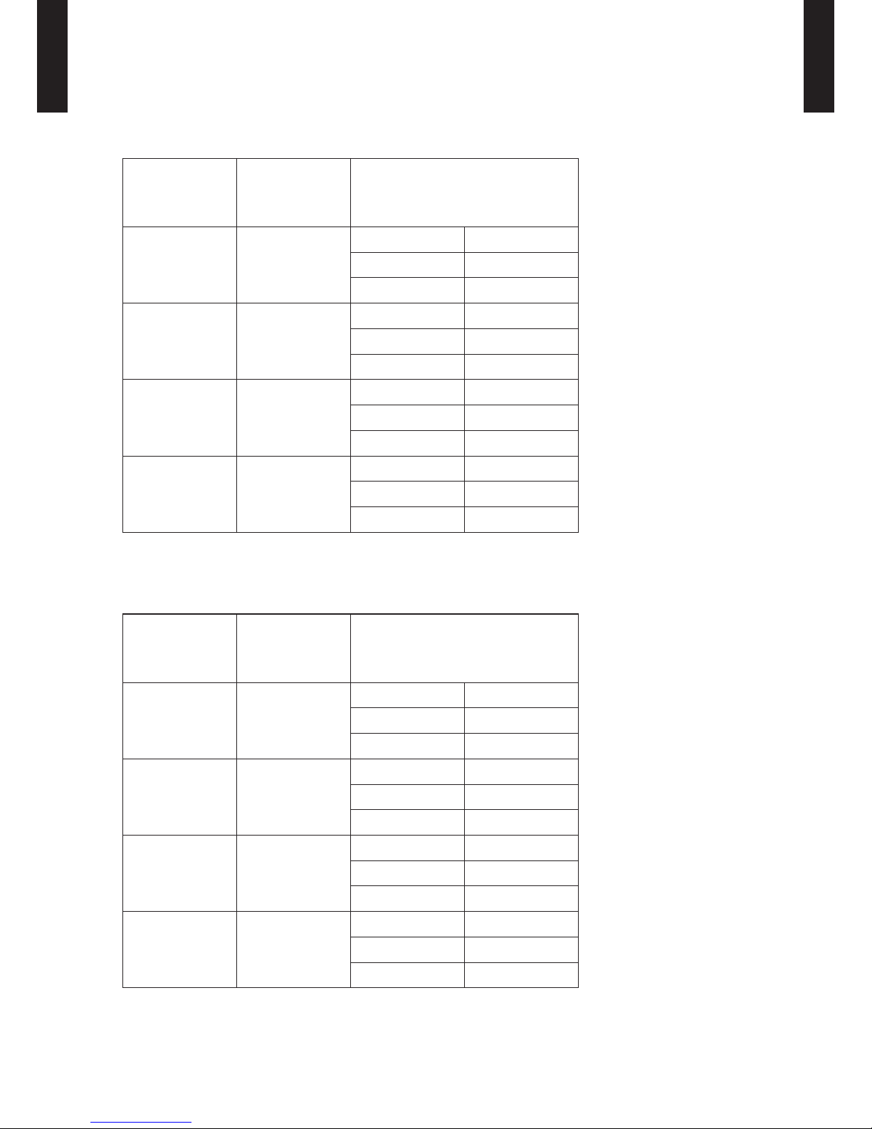
CAPACITY COMPENSATION RATE FOR PIPE LENGTH 7.
AND HEIGHT DIFFERENCE
MODEL: AO
G45LETL
Height difference H
HH
1 Indoor unit is higher than outdoor unit.
2 Indoor unit is lower than outdoor unit.
Outdoor unit
Outdoor unit
Connection pipe
Indoor unit
Indoor unit
Connection pipe
HEATING
Pipe length (m)
5 7. 5 10 20 30 40 50
Height
difference H
(m)
Û
1
Indoor unit is
higher than
outdoor unit.
30 - - - - 0.978 0.968 0.958
20 - - - 0.988 0.978 0.968 0.958
10 - - 0.998 0.988 0.978 0.968 0.958
7. 5 - 1.000 0.998 0.988 0.978 0.968 0.958
5 1.000 1.000 0.998 0.988 0.978 0.968 0.958
0 1.000 1.000 0.998 0.988 0.978 0.968 0.958
Û
2
Indoor unit is
lower than
outdoor unit.
-5 0.998 0.995 0.993 0.983 0.973 0.963 0.953
-7. 5 - 0.993 0.991 0.981 0.971 0.961 0.9 51
-10 - - 0.988 0.978 0.968 0.958 0.948
-20 - - - 0.968 0.958 0.949 0.939
-30 - - - - 0.949 0.939 0.929
COOLING
Pipe length (m)
5 7. 5 10 20 30 40 50
Height
difference H
(m)
Û
1
Indoor unit is
higher than
outdoor unit.
30 - - - - 0.879 0.846 0.814
20 - - - 0.926 0.893 0.861 0.828
10 - - 0.975 0.942 0.908 0.875 0.841
7. 5 - 0.988 0.979 0.946 0.912 0.878 0.845
5 0.992 0.992 0.983 0.949 0.916 0.882 0.848
0 1.000 1.000 0.991 0.957 0.923 0.889 0.855
Û
2
Indoor unit is
lower than
outdoor unit.
-5 1.000 1.000 0.991 0.957 0.923 0.889 0.855
-7. 5 - 1.000 0.991 0.957 0.923 0.889 0.855
-10 - - 0.991 0.957 0.923 0.889 0.855
-20 - - - 0.957 0.923 0.889 0.855
-30 - - - - 0.923 0.889 0.855
Page 43

- (02 - 10) -
OUTDOOR UNIT
AO
G45-54LETL
OUTDOOR UNIT
AO
G45-54LETL
MODEL: AO
G54LETL
Height difference H
HH
1 Indoor unit is higher than outdoor unit.
2 Indoor unit is lower than outdoor unit.
Outdoor unit
Outdoor unit
Connection pipe
Indoor unit
Indoor unit
Connection pipe
HEATING
Pipe length (m)
5 7. 5 10 20 30 40 50
Height
difference H
(m)
Û
1
Indoor unit is
higher than
outdoor unit.
30 - - - - 0.978 0.968 0.958
20 - - - 0.988 0.978 0.968 0.958
10 - - 0.998 0.988 0.978 0.968 0.958
7. 5 - 1.000 0.998 0.988 0.978 0.968 0.958
5 1.000 1.000 0.998 0.988 0.978 0.968 0.958
0 1.000 1.000 0.998 0.988 0.978 0.968 0.958
Û
2
Indoor unit is
lower than
outdoor unit.
-5 0.998 0.995 0.993 0.983 0.973 0.963 0.953
-7. 5 - 0.993 0.991 0.981 0.971 0.961 0.9 51
-10 - - 0.988 0.978 0.968 0.958 0.948
-20 - - - 0.968 0.958 0.949 0.939
-30 - - - - 0.949 0.939 0.929
COOLING
Pipe length (m)
5 7. 5 10 20 30 40 50
Height
difference H
(m)
Û
1
Indoor unit is
higher than
outdoor unit.
30 - - - - 0.871 0.837 0.803
20 - - - 0.921 0.886 0.851 0.816
10 - - 0.971 0.936 0.900 0.865 0.830
7. 5 - 0.988 0.975 0.940 0.904 0.868 0.833
5 0.992 0.992 0.979 0.943 0.908 0.872 0.836
0 1.000 1.000 0.987 0.951 0.915 0.879 0.843
Û
2
Indoor unit is
lower than
outdoor unit.
-5 1.000 1.000 0.987 0.951 0.915 0.879 0.843
-7. 5 - 1.000 0.987 0.9 51 0.915 0.879 0.843
-10 - - 0.987 0. 9 51 0.915 0.879 0.843
-20 - - - 0.951 0.915 0.879 0.843
-30 - - - - 0.915 0.879 0.843
Page 44

- (02 - 11) -
OUTDOOR UNIT
AO
G45-54LETL
OUTDOOR UNIT
AO
G45-54LETL
ADDITIONAL CHARGE CALCULATION8.
MODELS: AO
G45LETL, AOG54LETL
Refrigerant Charge
z
Refrigerant type R410A
Refrigerant amount g 3350
Total pipe length m 20 or less 30 40 50 (MAX)
40g/m
Additional charge g 0 400 800 120 0
Page 45

- (02 - 12) -
OUTDOOR UNIT
AO
G45-54LETL
OUTDOOR UNIT
AO
G45-54LETL
AIR FLOW9.
MODELS: AO
G45LETL, AOG54LETL
Cooling
z
Heating
z
MODEL
Number of
rotations
(r.p.m.)
Air ow
AOG45LETL
Upper fan 850
m
3
/h 6750
l/s 1875
Lower fan 800
CFM 3974
AOG54LETL
Upper fan 850
m
3
/h 6750
l/s 1875
Lower fan 800
CFM 3974
MODEL
Number of
rotations
(r.p.m.)
Air ow
AOG45LETL
Upper fan 780
m
3
/h 6200
l/s 172 2
Lower fan 750
CFM 3650
AOG54LETL
Upper fan
850
m3/h
6850
l/s
1903
Lower fan
830
CFM
4033
Page 46

- (02 - 13) -
OUTDOOR UNIT
AO
G45-54LETL
OUTDOOR UNIT
AO
G45-54LETL
OPERATION NOISE (SOUND PRESSURE)10.
NOISE LEVEL CURVE10-1.
MODEL: AO
G45LETL
Cooling
z
Octave ba nd sound p ressure level, dB:(0 dB= 0.00 02µbar)
Octave ba nd cente r frequ ency,Hz
80
70
60
50
40
30
20
10
0
63 125 250 500 1,000 2,000 4,00 0 8,00 0
NC-65
NC-60
NC-55
NC-50
NC-45
NC-40
NC-35
NC-30
NC-25
NC-20
NC -15
Heating
z
Octave ba nd sound p ressure level, dB:(0 dB= 0.00 02µbar)
Octave ba nd cente r frequ ency,Hz
80
70
60
50
40
30
20
10
0
63 125 250 500 1,000 2,000 4,00 0 8,00 0
NC-65
NC-60
NC-55
NC-50
NC-45
NC-40
NC-35
NC-30
NC-25
NC-20
NC -15
Heating
z
Octave ba nd sound p ressure level, dB:(0 dB= 0.00 02µbar)
Octave ba nd cente r frequ ency,Hz
80
70
60
50
40
30
20
10
0
63 125 250 500 1,000 2,000 4,00 0 8,00 0
NC-65
NC-60
NC-55
NC-50
NC-45
NC-40
NC-35
NC-30
NC-25
NC-20
NC -15
Octave ba nd sound p ressure level, dB:(0 dB= 0.00 02µbar)
Octave ba nd cente r frequ ency,Hz
80
70
60
50
40
30
20
10
0
63 125 250 500 1,000 2,000 4,00 0 8,00 0
MODEL: AO
G54LETL
Cooling
z
NC-65
NC-60
NC-55
NC-50
NC-45
NC-40
NC-35
NC-30
NC-25
NC-20
NC -15
Page 47

- (02 - 14) -
OUTDOOR UNIT
AO
G45-54LETL
OUTDOOR UNIT
AO
G45-54LETL
SOUND LEVEL CHECK POINT10-2.
Microphone
1m
Microphone
Airflow
Page 48

- (02 - 15) -
OUTDOOR UNIT
AO
G45-54LETL
OUTDOOR UNIT
AO
G45-54LETL
ELECTRIC CHARACTERISTICS11.
Model name AOG45LETL AOG54LETL
Power supply
Voltage V 230 ~
Frequency Hz 50
*1) Max. operating current A 22.5 23.5
*2) Wiring spec.
Circuit breaker current A 30
Power cable mm
2
6.0
*1) The maximum current is the total current of indoor unit and outdoor unit.
*2) Wiring spec. :
Selected sample
(Selected based on Japan Electrotechnical Standards and Codes Committee E0005)
Page 49

- (02 - 16) -
OUTDOOR UNIT
AO
G45-54LETL
OUTDOOR UNIT
AO
G45-54LETL
SAFETY DEVICES12.
Protection form
Model
AOG45LETL AOG54LETL
Circuit protection
Current fuse
(Filter printed circuit board)
250V 30A, 250V 10A x2, 250V 3.15A
Current fuse
(Main printed circuit board)
250V 3.15A
Fan motor protector Thermal protector
OFF : 150±15°C
ON : 120±15°C
Compressor protection
Thermal protection program
(Compressor temp.)
OFF : 108°C
ON : 80°C
Thermal protection program
(Discharge temp.)
OFF : 110°C
ON : After 7 minutes
High pressure protection Pressure switch
OFF : 4.2±0.1MPa
ON : 3.2±0.15MPa
Low pressure protection Pressure sensor
OFF : 0.12MPa
ON : 0.15MPa
Page 50

- (02 - 17) -
OUTDOOR UNIT
AO
G45-54LETL
OUTDOOR UNIT
AO
G45-54LETL
EXTERNAL INPUT & OUTPUT13.
EXTERNAL INPUT13-1.
ON/OFF of the "Low noise mode" and "Peak cut mode" functions can be specied by external
signal.
LOW NOISE MODE
The following reduces the operating sound of the outdoor unit from the normal sound. •
The air conditioner is set to the "Low noise mode" when closing the contact input of a commercial
timer or ON/OFF switch to a connector on the outdoor control PC board.
* Performance may drop depending on the outside air temperature condition, etc.
Circuit diagram example
z
Outdoor unit
control PC board
Connector
1
2
Signal
Field supply
*10m
Connected unit
Ex.) Switch
Contact capacity : 24VDC or more, 10mA or more.
* Make the distance from the PC board to the connected unit within 10m.
Use the following parts and construct a circuit as shown above. •
Input Signal∙∙∙ON : Low noise mode, Input Signal∙∙∙OFF : Normal operation •
*To set the "Low noise mode" level, refer to "13.FUNCTION SETTINGS".
ON
OFF
ON
OFF
Input Signal
Low noise mode
Parts (Optional)
z
Parts name External connect kit
Model name UT Y-XWZ XZ 3
Input Output Connector Remarks
Low noise mode ― CN10
See external
input/output settings
for details.
Peak cut mode ― CN11
― Error status CN12
― Compressor status CN13
Page 51

- (02 - 18) -
OUTDOOR UNIT
AO
G45-54LETL
OUTDOOR UNIT
AO
G45-54LETL
PEAK CUT MODE
Operation that suppressed the current value can be performed by means of the following on- •
site work. The air conditioner is set to the Peak cut mode when closing the contact input of a
commercial ON/OFF switch to a connector on the outdoor control PC board.
Circuit diagram example
z
Contact capacity : 24VDC or more, 10mA or more.
Outdoor unit
control PC board
Connector
1
2
Signal
Field supply
*10m
Connected unit
Ex.) Switch
* Make the distance from the PC board to the connected unit within 10m.
Use the following parts and construct a circuit as shown above. •
Input Signal∙∙∙ON : Peak cut mode, Input Signal∙∙∙OFF : Normal operation •
*To set the "Peak cut mode" level, refer to "13.FUNCTION SETTINGS".
ON
OFF
ON
OFF
Input Signal
Peak cut mode
Parts (Optional)
z
Parts name External connect kit
Model name UT Y-XWZ XZ 3
Page 52

- (02 - 19) -
OUTDOOR UNIT
AO
G45-54LETL
OUTDOOR UNIT
AO
G45-54LETL
EXTERNAL OUTPUT13-2.
ERROR STATUS OUTPUT
An air conditioner error status signal is produced when a malfunction occurs. •
Circuit diagram example
z
1) Power supply
●Voltage (Chart sign=Vcc) : DC 24V or less
2) Load
● Load : DC 500mA or less is recommended
Signal
Outdoor unit
control PC board
Connected unit
Connector
1
2
Field supply
*10m
Vcc
+
+
-
Load
Vcc
Power
supply
* Make the distance from the PC board to the connected unit within 10m.
Error
Normal
ON
OFF
Error status
Output signal
Parts (Optional)
z
Parts name External connect kit
Model name UT Y-XWZ XZ 3
Page 53

- (02 - 20) -
OUTDOOR UNIT
AO
G45-54LETL
OUTDOOR UNIT
AO
G45-54LETL
COMPRESSOR STATUS OUTPUT
Compressor operation status signal is produced when the compressor is running. •
Circuit diagram example
z
1) Power supply
●Voltage (Chart sign=Vcc) : DC 24V or less
2) Load
● Load : DC 500mA or less is recommended
Signal
Outdoor unit
control PC board
Connected unit
Connector
1
2
Field supply
*10m
Vcc
+
+
-
Load
Vcc
Power
supply
* Make the distance from the PC board to the connected unit within 10m.
ON
OFF
Operation
Stop
Compressor
Output signal
status
Parts (Optional)
z
Parts name External connect kit
Model name UT Y-XWZ XZ 3
Page 54

- (02 - 21) -
OUTDOOR UNIT
AO
G45-54LETL
OUTDOOR UNIT
AO
G45-54LETL
FUNCTION SETTINGS14.
FIELD SETTING SWITCHES14-1.
The positions of the switches on the outdoor unit control board are shown in the gure below.
FUNCTIONS
Caution
Discharge the static electricity from your body before setting up the push buttons.
Never touch the terminals or the patterns on the parts that are mounted on the board.
Terminal blocks
Push
buttons
LED lamps
Display lamp Function or operation method
(1) POWER / MODE Green
Lights on while power on.
Local set ting in outdoor unit or error
code is displayed with blink.
(2) ERROR Red Blinks during abnormal operation.
(3) PUMP DOWN (L1) Orange
Lights on during pump down
operation.
(4) LOW NOISE MODE
(L2,L3)
Orange
Lights on during “Low noise” mode
when local setting is activated.
(Lighting pattern of L2 and L3
indicates low noise level)
(5) PEAK CUT MODE
(L4,L5,L6)
Orange
Lights on during “Peak cut” mode
when local setting is activated.
(Lighting pattern of L4, L5 and L6
indicates peak cut level)
Button Function or operation method
SW1 MODE
To switch between “Local setting”
and “Error code display”.
SW2 SELECT
To switch between the individual
“Local settings” and the “ Error code
displays”.
SW3 ENTER
To x between the individual “Local
settings” and the “Error code
displays”.
SW4 EXIT
To return to “Operation status
display”.
SW5
PUMP
DOWN
To start the pump down operation.
SW1
SW2
SW3 SW4 SW5
(1)
(2)
(3)
(4)
(5)
LED lamp
Page 55

- (02 - 22) -
OUTDOOR UNIT
AO
G45-54LETL
OUTDOOR UNIT
AO
G45-54LETL
SETTING METHOD14-2.
Stop the operation of air conditioner before this setting.
LOW NOISE MODE14-2-1.
SW1
SW2
SW3 SW4 SW5
LED lamp part
(1) Switch to “Local setting mode” by pressing [MODE] button (SW1) for 3 seconds or more.
(2) Conrm that the (POWER / MODE) blinks 9 times, then press [ENTER] button (SW3).
POWER
MODE
ERROR
(L1) (L2) (L3) (L4) (L5) (L6)
PUMP
DOWN
LOW NOISE PEAK CUT
Blinks
(9 times)
Sign “ ” : Lights off
(3) Press [SELECT] button (SW2), and adjust LED lamp as shown below. (Current setting is
displayed)
(L2)
(L3)
LOW NOISE
Blink
LOW NOISE
MODE
(4) Press [ENTER] button (SW3).
(L2) (L3)
LOW NOISE
LOW NOISE
MODE
Sign “ ” : Lights on
(5) Press [SELECT] button (SW2), and adjust LED lamp as shown in below gure.
PEAK CUT
MODE 1: Rated noise value -2dB
MODE 2: Rated noise value -4dB
Blink
Blink
(L4) (L5) (L6)
The noise of MODE2 is lower than that of MODE1.
(6) Press [ENTER] button (SW3) to x it.
PEAK CUT
MODE 1: Rated noise value -2dB
MODE 2: Rated noise value -4dB
(L4) (L5) (L6)
(7) Return to “Operating status display (Normal operation)” by pressing [EXIT] button (SW4).
• To restart the setting during the process, return to "Operating status display (Normal operation)" by pressing the [EXIT]
button once.
Page 56

- (02 - 23) -
OUTDOOR UNIT
AO
G45-54LETL
OUTDOOR UNIT
AO
G45-54LETL
PEAK CUT MODE14-2-2.
SW1
SW2
SW3 SW4 SW5
LED lamp part
(1) Switch to “Local setting mode” by pressing [MODE] button (SW1) for 3 seconds or more.
(2) Conrm that the (POWER / MODE) blinks 9 times, then press [ENTER] button (SW3).
POWER
MODE
ERROR
(L1) (L2) (L3) (L4) (L5) (L6)
PUMP
DOWN
LOW NOISE PEAK CUT
Blinks
(9 times)
Sign “ ” : Lights off
(3) Press [SELECT] button (SW2), and adjust LED lamp as shown below. (Current setting is
displayed)
(L2)
(L3)
LOW NOISE
Blink
PEAK CUT
MODE
(4) Press [ENTER] button (SW3).
(L2) (L3)
LOW NOISE
PEAK CUT
MODE
Sign “ ” : Lights on
(5) Press [SELECT] button (SW2), and adjust LED lamp as shown in below gure.
0% of rated input ratio
50% of rated input ratio
75% of rated input ratio
100% of rated input ratio
Blink
Blink Blink
Blink
Blink
PEAK CUT
(L4) (L5) (L6)
(6) Press [ENTER] button (SW3) to x it.
0% of rated input ratio
50% of rated input ratio
75% of rated input ratio
100% of rated input ratio
PEAK CUT
(L4) (L5) (L6)
(7) Return to “Operating status display (Normal operation)” by pressing [EXIT] button (SW4).
• To restart the setting during the process, return to "Operating status display (Normal operation)" by pressing the
[EXIT] button once.
Page 57

- (02 - 24) -
OUTDOOR UNIT
AO
G45-54LETL
OUTDOOR UNIT
AO
G45-54LETL
OPTIONAL PARTS15.
Exterior Parts name Model No. Summary
External connect
kit
UTY-XWZXZ3
Use to operate the External input
and output function of Outdoor
unit.
 Loading...