

Page 1

SPLIT TYPE
AMP Air Conditioning
www.ampair.co.uk | sales@ampair.co.uk
ROOM AIR CONDITIONER
WALL MOUNTED
INVERTER
SERVICE
INSTRUCTION
Models Indoor unit Outdoor unit
AS*G30LMTA
AS*G36LMTA
#RSG30LMTA #ROG30LMTA
#RSG36LMTA #ROG36LMTA
type
AO*G30LMTA
AO*G36LMTA
Page 2

CONTENTS
AMP Air Conditioning
www.ampair.co.uk | sales@ampair.co.uk
1. DESCRIPTION OF EACH CONTROL OPERATION
1. COOLING OPERATION................................................................................................
2. HEATING OPERATION.................................................................................................
3. DRY OPERATION.........................................................................................................
4. AUTO CHANGEOVER OPERATION............................................................................
5. INDOOR FAN CONTROL..............................................................................................
6. OUTDOOR FAN CONTROL..........................................................................................
7. LOUVER CONTROL.....................................................................................................
8. COMPRESSOR CONTROL..........................................................................................
9. TIMER OPERATION CONTROL...................................................................................
10. ELECTRONIC EXPANSION VALVE CONTROL........................................................
11. TEST OPERATION CONTROL...................................................................................
12. PREVENT TO RESTART FOR 3 MINUTES (3 MINUTES ST)...................................
13. FOUR-WAY VALVE EXTENSION SELECT................................................................
14. AUTO RESTART.........................................................................................................
15. MANUAL AUTO OPERATION (Indoor unit body operation).......................................
16. FORCED COOLING OPERATION..............................................................................
17. COMPRESSOR PREHEATING..................................................................................
01-01
01-02
01-02
01-03
01-05
01-07
01-08
01-09
01-11
01-14
01-14
01-14
01-15
01-15
01-15
01-15
01-16
18. 10°C HEAT OPERATION............................................................................................
19. ECONOMY OPERATION............................................................................................
DEFROST OPERATION CONTROL...........................................................................
20.
21. OFF DEFROST OPERATION CONTROL...................................................................
22. VARIOUS PROTECTIONS.......................................................................................... 01-20
23. LOW NOISE OPERATION...........................................................................................01-22
24. HUMAN SENSOR (Energy Saving).............................................................................
25. POWERFUL OPERATION...........................................................................................
26. SERVER ROOM CONTROL.......................................................................................
2. TROUBLE SHOOTING
2-1 ERROR DISPLAY.......................................................................................................
2-1-1 INDOOR UNIT AND WIRED RMOTE CONTROLLER DISPLAY ......................
2-1-2 WIRED REMOTE CONTROLLER DISPLAY (OPTION).....................................
2-2 TROUBLE SHOOTING WITH ERROR CODE............................................................
2-3 TROUBLE SHOOTING WITH NO ERROR CODE......................................................
2-4 SERVICE PARTS INFORMATION.............................................................................. 02-35
01-16
01-16
01-17
01-19
01-23
01-23
01-24
02-01
02-01
02-02
02-03
02-30
3. APPENDING DATA
3-1 FUNCTION SETTING.................................................................................................
3-2 THERMISTOR RESISTANCE VALUES..................................................................... 03-06
3-3 EXTERNAL INPUT AND OUTPUT............................................................................. 03-08
3-4 BUZZER SOUND........................................................................................................ 03-20
03-01
Page 3

WALL MOUNTED type
AMP Air Conditioning
www.ampair.co.uk | sales@ampair.co.uk
INVERTER
1 . DESCRIPTION OF EACH
CONTROL OPERATION
Page 4

1. COOLING OPERATION
AMP Air Conditioning
www.ampair.co.uk | sales@ampair.co.uk
1-1 COOLING CAPACITY CONTROL
A sensor (room temperature thermistor) built in the indoor unit body will usually perceive
difference or variation between a set temperature and present room temperature, and
controls the operation frequency of the compressor.
* If the room temperature is 6.0°C higher than a set temperature, the compressor operation
frequency will attain to maximum performance.
* If the room temperature is 1.0°C lower than a set temperature,
the compressor will be stopped.
* When the room temperature is between +6.0°C to -1.0°C of the setting temperature,
the compressor frequency is controlled within the range shown in Table1.
However, the maximum frequency is limited in the range shown in Figure1 based on the
fan speed mode and the outdoor temperature.
( Table 1 : Compressor Frequency Range )
Outside air Outside air
temperature drops temperature rises
34°C
30°C
19°C
10°C
0°C
minimum
frequency
14rps 72rps
( Fig.1 : Limit of Maximum Frequency based on Outdoor Temperature )
A zone
B zone
C zone
D zone
E zone
maximum
frequency
36°C
32°C
21°C
12°C
2°C
Hi Me Lo Quiet
A zone 72rps 50rps 37rps 20rps
B zone 72rps 50rps 37rps 20rps
C zone 56rps 42rps 32rps 20rps
D zone 42rps 37rps 27rps 17rps
E zone 42rps 37rps 27rps 17rps
F zone 42rps 37rps 27rps 17rps
F zone
01-01
Page 5

2. HEATING OPERATION
AMP Air Conditioning
www.ampair.co.uk | sales@ampair.co.uk
2-1 HEATING CAPACITY CONTROL
A sensor (room temperature thermistor) built in the indoor unit body will usually perceive
difference or variation between a set temperature and present room temperature, and
controls the operation frequency of the compressor.
* If the room temperature is lower by 6.0°C than a set temperature, the compressor operation
frequency will attain to maximum performance.
* If the room temperature is 1.0°C higher than a set temperature,
the compressor will be stopped.
* When the room temperature is between +1.0°C to -6.0°C of the setting temperature,
the compressor frequency is controlled within the range shown in Table2.
( Table 2 : Compressor Frequency Range )
minimum
frequency
16rps 90rps
maximum
frequency
3. DRY OPERATION
3-1 INDOOR UNIT CONTROL
The compressor rotation frequency shall change according to the temperature, set temperature,
and room temperature variation which the room temperature sensor of the indoor unit body has
detected as shown in the Table3.
( Table3 : Compressor frequency )
Operating
frequency
X zone 20rps
J zone
Y zone
17rps
0rps
( Fig.2 : Compressor Control based on Room Temperature )
Room
temperature drops
Ts+0.5°C
Ts -1.5°C
X zone
J zone
Y zone
Room
temperature rises
Ts+1.5°C
Ts -0.5°C
01-02
Page 6

4. AUTO CHANGEOVER OPERATION
AMP Air Conditioning
www.ampair.co.uk | sales@ampair.co.uk
When the air conditioner is set to the Auto mode by remote controller, operation starts in the optimum
mode from among the Heating, Cooling, and Monitoring mode. During operation, the
optimum mode is automatically switched in accordance with temperature changes. The temperature
can be set between 18°C and 30°C in 1.0°C steps.
When operation starts, indoor fan and outdoor fan are operated for around 1 minutes.
1
Room temperature and outdoor temperature are sensed, and the operation mode is selected
in accordance with the table below. <Monitoring mode>
( Table 4 : Operation mode selection table )
Room temperature (TR)
Operation mode
TR : Room temperature
Ts : Setting temperature
TR> Ts+2°C
Ts+2°C TR Ts -2°C
TR < Ts -2°C Heating
Cooling
*Middle zone
*If it's Middle zone, operation mode of indoor unit is selected as below.
(1). Same operation mode is selected as outdoor unit.
If outdoor unit is operating in Cooling and Heating mode,
indoor unit will be operated by the same operation mode.
(2). Selected by the outdoor temperature.
If outdoor unit is operating in other than Cooling and Heating mode, indoor unit will be operated
according to the outdoor temperature as below.
( Fig.3 : Outdoor temperature zone selection )
Temperature
25
°C and over
25°C under
2
When the compressor was stopped for 6 consecutive minutes by the temperature control function
after the Cooling or Heating mode was selected at above, operation is switched
to Monitoring and the operation mode is selected again.
Mode
Cooling
Heating
1
3
When the middle zone is selected on the predetermining of the operation mode, the operation mode
before the changing to the monitor mode is selected.
01-03
Page 7

AUTO CHANGEOVER operation flow chart
AMP Air Conditioning
www.ampair.co.uk | sales@ampair.co.uk
START
Monitor mode
TS : Setting temperature
Room temp.
Ts+2
°C?
NO
Room temp.
°C?
Ts -2
NO
Middle zone
Auto change over is
second or more?
NO
YES
YES
NO
Operation mode
before the monitor mode is
cooling mode?
YES
YES
Thermostat remains
in OFF state for 6 minutes or
longer?
NO
YES
System stops
or operation command other than
auto changeover operation?
NO
Operation mode of
outdoor unit : Cooling?
YES
Operation mode of outdoor unit
YES
: Heating?
Outdoor temperature<
25°C?
01-04
NO
NO
NO
YES
COOLING OPERATIONHEATING OPERATION
Thermostat remains
in OFF state for 6 minutes or
longer?
NO
System stops
or operation command other than
auto changeover operation?
NO
YES
YES
Page 8

5. INDOOR FAN CONTROL
AMP Air Conditioning
www.ampair.co.uk | sales@ampair.co.uk
1. Fan speed
( Table4 : Indoor Fan Speed )
Operation mode Air flow mode
Heating
Cooling/ Fan
Dry
Powerful
Hi
Me+
Me
Lo
Quiet
Cool air prevention
S-Lo
Powerful
Hi
Me
Lo
Quiet
S-Lo
Speed (rpm)
1520
1370
1260
1150
950
780
600
540
1520
1370
1150
950
780
540
X zone: 780
J zone: 680
2. FAN OPERATION
The airflow can be switched in 5 steps such as AUTO, QUIET, LOW, MED, HIGH,
while the indoor fan only runs.
When Fan mode is set at [AUTO], it operates on [MED] Fan Speed.
3. COOLING OPERATION
Switch the airflow [AUTO], and the indoor fan motor will run according to a room temperature,
as shown in Figure3.
On the other hand, if switched in [HIGH] [QUIET], the indoor motor will run at a constant airflow of [COOL]
operation modes QUIET, LOW, MED, HIGH, as shown in Table4.
( Fig.3 : Airflow change - over ( Cooling : AUTO ) )
TR-Ts > 2.5°C
=
2.5°C > TR-Ts > 1.5°C
1.5°C > TR-Ts
TR-Ts > 2°C
2°C > TR-Ts > 1°C
1°C > TR-Ts
=
=
High mode
Med mode
Low mode
When the room
temperature drops
When the room
temperature rises
TR : Room temperature
Ts : Setting temperature
4. DRY OPERATION
Refer to the Table4.
During the dry mode operation, the fan speed setting can not be changed.
=
01-05
Page 9

5. HEATING OPERATION
AMP Air Conditioning
www.ampair.co.uk | sales@ampair.co.uk
Switch the airflow [AUTO], and the indoor fan motor will run according to a room temperature,
as shown in Figure4.
On the other hand, if switched in [HIGH] [QUIET], the indoor motor will run at a constant airflow
of [HEAT] operation modes QUIET, LOW, MED, HIGH, as shown in Table4.
( Fig.4 : Airflow change - over ( Heating : AUTO ) )
TR-Ts > -1°C
=
-1°C > TR-Ts > -2°C
=
When the room
temperature rises
Low mode
Med mode
When the room
temperature drops
TR-Ts > -1.5°C
=
-1.5°C > TR-Ts > -2.5°C
=
-2°C > TR-Ts
Med+ mode
-2.5°C > TR-Ts
TR : Room temperature
Ts : Setting temperature
6. COOL AIR PREVENTION CONTROL (Heating mode)
The maximum value of the indoor fan speed is set as shown in Figure5, based on the detected
temperature by the indoor heat exchanger sensor on heating mode.
( Fig.5 : Cool Air Prevention Control )
Indoor heat exchanger
temperature rises
Hi
42°C
39°C
37°C
30°C
or setting fan mode
*Me+
or setting fan mode
*Lo
or setting fan mode
Cool air
prevention
Indoor heat exchanger
temperature drops
S-Lo
*Lower speed is selected.
37°C
34°C
32°C
28°C
7. MOISTURE RETURN PREVENTION CONTROL (Cooling mode& Dry mode)
Switch the airflow [AUTO] at cooling mode, and the indoor fan motor will run as shown in Figure6.
( Fig.6 : Indoor Fan Control )
Compressor
ON
OFF
Indoor fan
Setting air flow
Indoor fan
(as shown in Table 5)
S-Lo
OFF
10 30 60 180 60 180 60 10 30
( Table5 : Indoor fan speed )
X zone J zone Y zone
30,36LMTA 780rpm 680rpm 680rpm 780rpm
(SEC)
Dry
Cooling
01-06
Page 10

6. OUTDOOR FAN CONTROL
AMP Air Conditioning
www.ampair.co.uk | sales@ampair.co.uk
1. Outdoor Fan Motor
Following table shows the type of the outdoor fan motor. The control method is different
between AC motor and DC motor.
2. Fan Speed
( Table 7 : Outdoor fan speed )
Zone
Y
Z
30LMTA
F
G 270/ 230/ 200
H 240/ 220/ 200
Cooling Heating
850/ 800/ 620/ 500/ 400
850/ 800/ 620/ 500/ 400
500/ 320/ 230
Dry
550/ 450
550/ 450
500/ 320/ 230
270/ 230/ 200
240/ 220/ 200
(rpm)
900/ 850/ 800/ 620/ 550/ 450
36LMTA
Zone
Y
Z
G
H
Cooling Heating
900/ 800/ 620/ 500/ 400
900/ 800/ 620/ 500/ 400
F
500/ 320/ 230
270/ 230/ 200
240/ 220/ 200
Dry
550/ 450
550/ 450
500/ 320/ 230
270/ 230/ 200
240/ 220/ 200
900/ 800/ 620/ 550/ 450
Refer to Fig. 7
( Fig.7 : Outside air temperature zone selection )
Outside air
temperature
21°C
12°C
2°C
- 8°C
The outdoor fan speed mentioned above depends on the compressor frequency.
*
Y zone
Z zone
F zone
G zone
H zone
Outside air
temperature
19°C
10°C
0°C
- 10°C
(When the compressor frequency increases, the outdoor fan speed also changes to the higher
speed. When the compressor frequency decreases, the outdoor fan speed also changes to the
lower speed.)
After the defrost control is operated on the heating mode, the fan speed keeps at the higher speed
*
as table 9 without relating to the compressor frequency.
( Table 9 : Outdoor fan speed after the defrost )
30,36LMTA 900rpm
01-07
Page 11

7. LOUVER CONTROL
AMP Air Conditioning
www.ampair.co.uk | sales@ampair.co.uk
1. VERTICAL LOUVER CONTROL
(Function Range)
Each time the button is pressed, the air direction range will change as follow:
Types of Airflow Direction Setting:
: During Heating/ Cooling/ Dry modes
, , ,
, ,
The Remote Controller's display does not change.
1
2
3
4
5
6
Use the air direction adjustments within the ranges shown above.
The vertical airflow direction is set automatically as shown, in acc
During Cooling / Dry mode : Horizontal flow
During Heating mode : Downward flow
ordance with the type of operation selected.
when the Server room setting is activate,
the direction is set to
2wire Remote controller : ~
During AUTO mode operation, for the first a few minutes after beginning operation,
airflow will be horizontal ; the air direction cannot be adjusted during this period.
The airflow direction setting will temporarily become when the temperature of
the airflow is low at the start of the Heating mode.
After beginning of AUTO/HEAT mode operated and automatic defrosting operation time,
the air flow will be horizontal .
However, the Airflow Direction cannot be adjusted at beginning AUTO operation mode.
2. HORIZONTAL LOUVER CONTROL
(Function Range)
Each time the button is pressed, the air direction
range will change as follows.
,
Cooling / Heating / Dry mode / Fan mode
1
3
2
5
4
The Remote Controller's display does not change.
3. SWING OPERATION
To select Vertical Airflow Swing Operation
When the swing signal is received from the remote controller, the vertical louver starts to swing.
(Swinging Range)
Cooling mode / Dry mode / Fan mode( ) :
Heating mode / Fan mode( ) :
4 6
1 3
1
3 6
4
When the indoor fan is S-Lo or Stop mode, the swing operation is interrupted
and it stops at either upper end or bottom end.
To select Horizontal Airflow Swing Operation
When the swing signal is received from the remote controller, the horizontal louver starts to swing.
(Swinging Range)
All mode :
1
5
When the indoor fan is S-Lo or Stop mode, the swing operation is interrupted
and it stops at either upper end or bottom end.
To select Vertical and Horizontal Airflow Swing Operation
When the horizontal swing signal is input from remote control, the combination of the vertical
and horizontal swing operation is performed.
when the Server room settingis activate,
the direction is set to
1
6
01-08
Page 12

8. COMPRESSOR CONTROL
AMP Air Conditioning
www.ampair.co.uk | sales@ampair.co.uk
1. OPERATION FREQUENCY RANGE
The operation frequency of the compressor is different based on the operation mode as
shown in Table 10.
(Table 10 : Compressor Operation Frequency Range)
Cooling/ Dry /Heating
Min
16rps 90rps
Max
2. OPERATION FREQUENCY CONTROL AT START UP
The compressor frequency soon after the start-up is controlled as shown in Fig.8.
(Fig.8 : Compressor Control at Start-up)
< Normal start-up >
Frequency
Frequency
Frequency
Time
Time Time
1. Normal
(Frequency)
Frequency
30rps 47rps 60rps
Frequency
Frequency
(Time)
Time
60sec 120sec 180sec
Time Time
Normal operation
* Cooling and dry mode.
* Below 3 hours from the compressor stop and the compressor thermistor > 32 C in
heating mode.
* After defrost operation.
2. Special
(Frequency)
Frequency
30rps 47rps 60rps
Frequency
Frequency
(Time)
Time
60sec 180sec 240sec
Time Time
Special operation
* Other than normal operation condition.
* First turn on.
01-09
Page 13

9. TIMER OPEARTION CONTROL
AMP Air Conditioning
www.ampair.co.uk | sales@ampair.co.uk
9-1 WIRELESS REMOTE CONTROLLER
The table12 shows the available timer setting based on the product model.
( Table 12 : Timer Setting )
ON/OFF TIMER PROGRAM TIMER SLEEP TIMER WEEKLY TIMER
1. ON TIMER/ OFF TIMER
OFF timer : When the clock reaches the set time, the air conditioner will be turned off.
Operation mode
Stop mode
Set time of timer
ON timer : When the clock reaches the set time, the air conditioner will be turned on.
Operation mode
Stop mode
Set time of timer
2. PROGRAM TIMER
The program timer allows the OFF timer and ON timer to be used in combination one time.
Operation mode
Stop mode
Set time Set time Set time Set time
Operation will start from the timer setting (either OFF timer or ON timer) whichever is closest
to the clock's current timer setting.
The order of operations is indicated by the arrow in the remote control unit's display.
SLEEP timer operation cannot be combined with ON timer operation.
Operation mode
Operation mode
Stop mode
Stop mode
01-11
Page 14

3. SLEEP TIMER
AMP Air Conditioning
www.ampair.co.uk | sales@ampair.co.uk
If the sleep is set, the room temperature is monitored and the operation is stopped automatically.
If the operation mode or the set temperature is change after the sleep timer is set, the operation is
continued according to the changed setting of the sleep timer from that time ON.
utomatically.
e operation is
In the cooling operation mode
When the sleep timer is set, the setting temperature is increased 1°C
It increases the setting temperature another 1°C after 1 hour.
After that, the setting temperature is not changed and the operation is stopped at the time
of timer setting.
Set temperature rises
( Ts : Set temperature )
+2°C
+1°C
Ts
Set
Stop of operation
60min0
In the heating operation mode
When the sleep timer is set, the setting temperature is decreased 1°C.
It decreases the setting temperature another 1°C every 30 minutes.
Upon lowering 4°C, the setting temperature is not changed and the operation stops at
the time of timer setting.
Set temperature lowers
( Ts : Set temperature )
Ts
-1°C
-2°C
-3°C
-4°C
Stop of operation
Set
30min
30min
30min
4. WEEKLY TIMER
ON and OFF timer can be combined, and up to 4 reservations per day and 28 reservations per week.
Before setting the program, please set the week and time of the air conditioner first.
If the week and time are not set, the weekly timer will not operate correctly at the set time.
01-12
Page 15

9-2 WIRED REMOTE CONTROLLER (OPTION)
AMP Air Conditioning
www.ampair.co.uk | sales@ampair.co.uk
The table13 shows the available timer setting based on the product model.
( Table13 : Timer Setting )
ON TIMER / OFF TIMER WEEKLY TIMER DAY OFF
1. ON TIMER / OFF TIMER
Same to 9-1 1. ON TIMER / OFF TIMER and shown in those.
2. WEEKLY TIMER
This timer function can set operation times of the each day of the week.
All days can be set together,the weekly timer can be used to repeat the timer setting for all of the days.
ON OFF ON OFF ON OFF
Setting day Setting day Setting day
Set time Set time
3. DAY OFF setting
The DAY OFF setting is only available for days for which weekly settings already exist.
If the operating time carries over to the next day (during a next day setting), the effective
DAY OFF range will be set as shown below.
Normal
DAY OFF
Stop mode
Operation mode
Stop mode
Preceding day Next day
Operation mode
Stop mode
Setting day
Next day setting
DAY OFF
Operation mode
Stop mode
Stop mode
Operation mode
Stop mode
Preceding day Next daySetting day
The DAY OFF setting can only be set one time. The DAY OFF setting is cancelled automatically
after the set day has passed.
01-13
Page 16

10. ELECTRONIC EXPANSION VALVE CONTROL
AMP Air Conditioning
www.ampair.co.uk | sales@ampair.co.uk
The most proper opening of the electronic expansion valve is calculated and controlled under the
present operating condition based on the Table14.
The compressor frequency, the temperatures detected by the discharge temperature sensor, the
indoor heat exchanger sensor, the outdoor heat exchanger sensor,
and the outdoor temperature sensor.
( Table14 : The pulse range of the electronic expansion valve control )
Operation mode Pulse range
Cooling / Dry mode
Heating mode
At the time of supplying the power to the outdoor unit, the initialization of the electronic
expansion valve is operated (528 pulses are input to the closing direction).
between 53 to 480 pulses.
between 40 to 480 pulses.
11. TEST OPERATION CONTROL
Wirless remoe controller
The outdoor unit, may not operate, depending on the room temperature.
In this case, keep on pressing the MANUAL AUTO button of the indoor unit for more than 10 seconds.
The operation indicator lamp and timer indicator lamp will begin to flash simultaneously
during cooling test run. Then, heating test run will begin in about 3 minutes when HEAT is selected
by the remote control operation. To end test operation, press the remote controller START/STOP button.
The test operation procedure by using optional remote controllers, refer to the operatin manual of each
remote controllers.
This function is not available when the server room control is active
12. PREVENT TO RESTART FOR 3 MINUTES ( 3 MINUTES ST )
The compressor won't enter operation status for 3 minutes after the compressor is stopped,
even if any operation is given.
01-14
Page 17
13. FOUR-WAY VALVE EXTENSION SELECT
AMP Air Conditioning
www.ampair.co.uk | sales@ampair.co.uk
At the time when the air conditioner is switched from the cooling mode to heating mode, the
compressor is stopped, and the four-way valve is switched in 3 minutes later after
the compressor stopped.
14. AUTO RESTART
When the power was interrupted by a power failure, etc. during operation, the operation contents
at that time are memorized and when power is recovered, operation is automatically started with
the memorized operation contents.
When the power is interrupted and recovered during timer operation, since the timer operation time
is shifted by the time the power was interrupted, an alarm is given by blinking (7 sec ON/2 sec OFF)
the indoor unit body timer lamp.
[ Operation contents memorized when the power is interrupted ]
Operation mode
Set temperature
Set air flow
Timer mode and timer time
Set air flow Direction
S
wing
ECONOMY operation
10°C HEAT operation
Human sensor setting
Low noise operation
15. MANUAL AUTO OPERATION (Indoor unit body operation)
If MANUAL AUTO Button is set, the operation is controlled as shown in Table15.
If the remote control is lost or battery power dissipated, this function will work without the remote control.
(Table15)
Manual auto operation
OPERATION MODE Auto changeover
FAN CONT. MODE Auto
TIMER MODE Continuous (No timer setting available)
SETTING TEMP. 24°C
SETTING LOUVER Standard
SWING OFF
This function is not available when the server room control is active
16. FORCED COOLING OPERATION
If cooling operation is set, the operation is controlled as shown in Table16.
( Table16 )
Forced cooling operation
OPERATION MODE
FAN CONT. MODE
TIMER MODE
SETTING TEMP.
SETTING LOUVER
SWING
Cooling
Hi
Room Temp is not controlled
Initial : Horizontal
(It is changed follow as setting of remote controller)
OFF
Forced cooling operation is started when pressing MANUAL AUTO button for 10 seconds or more.
During the forced cooling operation, it operates regardless of room temperature sensor.
Operation LED and timer LED blink during the forced cooling operation. They blink for 1 second ON
and 1 second OFF on both operation LED and timer LED (same as test operation).
Forced cooling operation is released after 60 minutes of starting operation.
The FORCED COOLING OPERATION will start as shown in Table16.
This function is not available when the server room control is active
01-15
Page 18

17. COMPRESSOR PREHEATING
AMP Air Conditioning
www.ampair.co.uk | sales@ampair.co.uk
When the outdoor heat exchanger temperature is lower than 0°C and the heating operation has been
stopped for 0 minutes, power is applied to the compressor and the compressor is heated.
(By heating the compressor, warm air is quickly discharged when operation is started.)
When operation was started and when the outdoor heat exchanger temperature rises to 2°C or greater,
preheating is ended.
( Fig.10 : Compressor Preheating )
OFF
2°C
0°C
ON
When the outdoor temperature is lower than 20°C and the all operation mode has been
stopped for 30 minutes, power is applied to the compressor and the compressor is heated.
(By heating the compressor, warm air is quickly discharged when operation is started.)
When operation was started and when the outdoor temperature rises to 26°C or greater,
preheating is ended.
18. 10°C HEAT OPERATION
The 10°C HEAT operation functions by pressing 10°C HEAT button on the remote controller.
The 10°C HEAT operation is almost the same operation as below settings.
( Table17 )
Mode Heating
Setting temperature 10°C
Fan mode AUTO
19. ECONOMY OPERATION
The ECONOMY operation functions by pressing ECONOMY button on the remote controller.
The ECONOMY operation is almost the same operation as below settings.
( Table18 )
Mode Cooling/ Dry Heating
Target temperature Setting temp.+1°C Setting temp.-1°C
01-16
Page 19

20. DEFROST OPERATION CONTROL
AMP Air Conditioning
www.ampair.co.uk | sales@ampair.co.uk
1. CONDITION OF STARTING THE DEFROST OPERATION
The defrost operation starts when the outdoor heat exchanger temperature sensor (Tn) detects
the temperature lower than the values shown in Table19.
( Table 19 : Condition of starting Defrost Operation )
ST
1 time defrosting
after starting operation
Less than 22 min. 22 to 62 min. More t han 62 min.
Compressor integrating operation time
Does not operate
Defrosting after 2 time
ND
upon starting operation
Tn10 : Temperature of continuous operation at 10minutes.
Tnb : Back 5minutes temperature
Compressor integrating operation time
Less than 35 min. More than 35min.
Does not operate
Integrating defrost
(Constant monitoring)
*1 : If the compressor continuous operation time is less than 10 minutes, the OFF number of the compressor is counted.
If any defrost operated, the compressor OFF count is cleared.
More than 240 min.
(For long continuous operation)
- 3°C
- 9°C - 5°C
Tn-Tn10 < - 5deg
Tn-Tnb < - 2deg
However, Tn < - 6°C
Compressor integrating operation time
More than 215 min.
(For long continuous operation)
=
- 5°C
Less than 10min.*1
(For intermittent operation)
OFF count of the compressor
40 times.
2. CONDITION OF THE DEFROST OPERATION COMPLETION
Defrost operation is released when the conditions become as shown in Table20.
( Table20 : Defrost Release Condition )
Release Condition
Outdoor heat exchanger temperature sensor value is higher than
+13°C
or Compressor operation time has passed 15 minutes.
01-17
Page 20

3. Defrost Flow Chart
AMP Air Conditioning
www.ampair.co.uk | sales@ampair.co.uk
The defrosting shall proceed by the integrating operation time, outdoor temperature
and outdoor heat exchanger temperature as follows.
Heating operation start : Compressor ON
(Not defrosted for 10 minutes)
1st defrost
Compressor
integrating
operation:
Over 22 min.
Outdoor
heat exchanger
temperature:
Below - 9°C
Compressor
integrating
operation:
Over 62 min.
Outdoor
heat exchanger
temperature:
Below - 5°C
2nd and later defrost
Compressor
integrating
operation:
Over 35 min.
Tn-Tn10 < - 5deg
Tn-Tnb < - 2deg
However, Tn < - 6 °C
Defrost start
=
(Constant monitoring)
Compressor
OFF count :
40 times
(Less than 10min.)
Integrating defrost
Compressor
integrating
operation:
Over 240 min.
Outdoor
heat exchanger
temperature:
Below - 3°C
Compressor
integrating
operation:
Over 215 min.
Outdoor
heat exchanger
temperature:
Below - 5°C
Defrost Indicator:
[Operation lamp]
7 sec ON / 2 sec OFF
Compressor OFF
Outdoor fan motor OFF
30 sec later four - way valve OFF
35 sec later compressor ON
Outdoor heat exchanger temperature:
Over +13°C
or
Compressor ON time: Maximum 15 minutes
Defrost end
01-18
Page 21

21. OFF DEFROST OPEARTION CONTROL
AMP Air Conditioning
www.ampair.co.uk | sales@ampair.co.uk
When operation stops in the [Heating operation] mode, if frost is adhered to the outdoor unit heat
exchanger, the defrost operation will proceed automatically. In this time, if indoor unit operation
lamp flashes slowly (7 sec ON / 2 sec OFF), the outdoor unit will allow the heat exchanger to defrost,
and then stop.
1. OFF DEFROST OPERATION CONDITION
In heating operation, the outdoor heat exchanger temperature is less than -4°C,
compressor continuous operation more than 10 minutes, and
compressor operation integrating time lasts for more than 30 minutes.
2. OFF DEFROST END CONDITION
Release Condition
Outdoor heat exchanger temperature sensor value is higher than +13°C
or Compressor operation time has passed 15 minutes.
OFF Defrost Flow Chart
Heating operation stop
Outdoor heat exchanger temperature :
Below -4°C
Compressor continuous operation :
Over 10 minutes
Compressor integrating operation :
Over 30 minutes
Defrost start
Defrost Indicater:
[Operation lamp]
7 sec ON / 2 sec OFF
Outdoor heat exchanger temperature :
Over +13°C
Compressor ON time : Maximum 15 minutes
or
Defrost end
01-19
Page 22

22. VARIOUS PROTECTIONS
AMP Air Conditioning
www.ampair.co.uk | sales@ampair.co.uk
1. DISCHARGE GAS TEMPERATURE OVERRISE PREVENSION CONTROL
The discharge gas thermosensor (discharge thermistor : Outdoor side) will detect discharge gas
temperature.
When the discharge temperature becomes higher than Temperature , the compressor frequency
is decreased 20rps, and it continues to decrease the frequency for 20rps every 120 seconds until
the temperature becoms lower than Temperature .
When the discharge temperature becomes lower than Temperature , the control of the control of
the compressor frequency is released.
When the discharge temperature becomes higher than Temperature , the compressor is stopped
and the indoor unit LED starts blinking.
( Table 21 : Discharge Temperature Over Rise Prevension Control / Release Temperature )
Temperature
Temperature
Temperature
104°C 101°C 110°C
2. CURRENT RELEASE CONTROL
The compressor frequency is controlled so that the outdoor unit input current does not exceeds
the current limit velue that was set up with the outdoor temperature.
The compressor frequency returns to the designated frequency of the indoor unit at the time
when the frequency becomes lower than the release value.
( Table 22-1 : Current Release Operation Value / Release Value)
Model 30
[ Heating ]
TO (Control / Release)
10.0A / 9.5A
17°C
11.5A / 11.0A
12°C
14.5A / 14.0A
5°C
14.5A / 14.0A
[ Cooling ]
TO (Control / Release)
9.0A / 8.5A
50°C
10.0A / 9.5A
46°C
12.5A / 12.0A
40°C
14.5A / 14.0A
TO : Outdoor Temperature
Model 36
[ Heating ]
TO (Control / Release)
10.0A / 9.5A
17°C
11.5A / 11.0A
12°C
16.0A / 15.5A
5°C
18.0A / 17.5A
TO : Outdoor Temperature
[ Cooling ]
TO (Control / Release)
50°C
46°C
13.0A / 12.5A
40°C
16.5A / 16.0A
TO : Outdoor Temperature
3. ANTIFREEZING CONTROL (Cooling and Dry mode)
The compressor frequency is decrease on cooling & dry mode when the indoor heat exchanger
temperature sensor detects the temperature lower than Temperature .
Then, the anti-freezing control is released when it becomes higher than Temperature .
9.0A / 8.5A
10.0A / 9.5A
( Table 23 : Anti-freezing Protection Operation / Release Temperature )
Outdoor temperature
Over than 10°C *1
or 12°C *2
Less than 10°C *1
or 12°C *2
Temperature
*1. When the temperature rises.
*2. When the temperature drops.
Temperature
7°C
4°C
13°C
01-20
Page 23

4. COOLING PRESSURE OVERRISE PROTECTION
AMP Air Conditioning
www.ampair.co.uk | sales@ampair.co.uk
When the outdoor unit heat exchange sensor temperature rises to 67°C or greater the compressor is
stopped and trouble display is performed.
5. HIGH TEMPERATURE AND HIGH PRESSURE RELEASE CONTROL ( HEATING MODE )
On heating mode, the compressor frequency is controlled as following based on the detection value of the indoor
heat exchanger temperature sensor.
[ Control System ]
Indoor heat exchange
temperature rises
Compressor is stopped
63°C
55°C
53°C
The compressor frequency is
decreased 15rps(30) every
120seconds.
The compressor frequency is
decreased 2rps(30) every
120seconds.
It returns to the normal operation
Indoor heat exchange
temperature drops
Stable zone
50°C
6. COMPRESSOR TEMPERATURE PROTECTION
When the compressor temperature sensor detects higher than
108°C, the compressor is stopped.
The protection is released when the compressor temperature sensor detects 80°C
after 3 minutes of compressor stop.
7. HIGH PRESSURE PROTECTION
When the pressure switch becomes OFF (Open : higher than 4.2 MPa),
the compressor is stopped.
It is released when the pressure switch becomes ON (Close : lower than 3.2 MPa)
after 3 minutes of compressor stop.
01-21
Page 24

23. LOW NOISE OPERATION
AMP Air Conditioning
www.ampair.co.uk | sales@ampair.co.uk
The compressor speed and the outdoor unit fan speed are limited to reduce the operation noise
by External Input.
During the LOW NOISE OPERATION,
"CURRENT OVERLOAD OPERATION", "ECONOMY OPERATION" and "PEAK CUT OPERATION"
are effective, and the outdoor unit operates by lowest current of them.
However, during the DEFROST OPERATION, the compressor operates by the speed
for DEFROST OPERATION.
( Table 27 : Detail of Low Noise Operation )
Low Noise mode
Cooling
Outdoor fan speed
[rpm]
620
Compressor speed
[rps]
32
Model 30
Heating
Cooling
620
620
32
34
Model 36
Heating
620
34
*The performance drops when operating in the LOW NOISE OPERATION.
01-22
Page 25

24. HUMAN SENSOR (Energy Saving)
AMP Air Conditioning
www.ampair.co.uk | sales@ampair.co.uk
•
About the ENERGY SAVING Operation
If no one enters the room for approximately 20 minutes, the set temperature
will be automatically controlled.
(When someone comes back into the room, the human sensor will detect this,
and automatically revert to the original settings.)
(Table 28)
Operation mode
Cool / Dry
Heat
Auto
(if there is no one in the room for a while)
The set temperature will be increased by
a maximum of approximately 2
The set temperature will be decreased by
a maximum of approximately 4
This runs the ENERGY SAVING function
automatically for the selected mode
Operation details
°C.
°C.
* High limit : 30°C
* Low limit : 16°C
(Cooling/ Heating/ Drying)
Application range is follows.
Vertical angle 90
°(Side view)
Horizontal angle 100
°(Top view)
ENERGY SAVING function may not work when the room temperature is very
different from the temperature defined in temperature setting,
such as when immediately after starting the operation
About the HUMAN SENSOR
• Details about detection with the human sensor
• The human sensor detects whether there are people in the room
by looking for movement by people in the room.
25. POWERFUL OPERATION
The Powerful operation functions by pressing POWERFUL button on the remote controller.
The indoor unit & outdoor unit will operate at maximum power as shown in Table 18.
(Table 29)
Powerful operation
COMPRESSOR FREQUENCY Maximum
FAN CONT. MODE Powerful
SETTING LOUVER Cooling/ Dry : 3, Heating : 5
Release Condition is as follows.
[Cooling / Dry]
- Room tenperature < Setting temperature - 0.5°C or Operation time has passed 20 minutes.
[Heating]
- Room tenperature > Setting temperature +0.5°C or Operation time has passed 20 minutes.
=
=
01-23
Page 26

26. SERVER ROOM CONTROL
AMP Air Conditioning
www.ampair.co.uk | sales@ampair.co.uk
Operation:
Cooling operation can be performed even in the low outdoor temperature and low humidity environment. In addition, the following interlock operation is possible by connecting two indoor
units with a cable.
1. System configuration
Necessary items
- 30, 36LMTA: 2 systems
Pipes / Power cable
- UTY-XWNX: 2pcs
- Indoor unit communicatoin cable
- Wireless remote controller
(Wired remote controller is not available)
UTY-XWNX
UTY-XWNX
Indoor unit communication cable (Local purchased)
Data exchanging:
“ON/OFF”, “Operating status”, ”Error”,
“Set point attainment monitoring”
2. Available Functions
• Alternative operation: 2 units operate alternately.
• Backup operation: In case one unit breaks down,
• Supporting operation: Both units operate simulta
the other unit starts operation automatically.
neously when the loaded capacity is not enough
with one unit.
3. Controlling
The control specification (Compressor operation control, Outdoor unit FAN control, EEV control,
Protection Function and abnormal deisplay) belongs to the original controlling specification of one
system.
4. Operation specification
When Server room control is activated by changing the setting on function setting 96, this
product maintains the room temperature constant by performing 3 types of operations automatically
according to the room temperature conditions.
While this function is activated, contents of operation is fixed as follows:
Operation mode Set temperature Airflow mode
*: Set temperature correction (±4 °C) is possible by switching the setting value on function setting 30.
The temperature correction has to be set with the same value on both indoor units.
(when the correction setting are not the same, the temperature controlling or the supporting
operation might not work properly.)
For the setting details, refer to the technical manual.
HGIH*C° 42LOOC
01-24
Page 27

5. Precautions & Restrictions
AMP Air Conditioning
www.ampair.co.uk | sales@ampair.co.uk
1) While performing Server room control, the following function cannnot be used.
• Operation modes other than cooling
• Airflow modes other than HIGH
• POWERFUL mode
• 10 HEAT operation
• ECONOMY operation
• On/Off timer, Program time, and Sleep timer
• Weekly timer on the secondary unit
• Human sensor function
• Starting operation on the secondary unit
• Temperature setting other than 24 *
* Temperature correction is possible
2) For stopping the system operation, shutdown the power supply.
*Stop operation by the Remote controller is impossible.
3) For canceling the server room control, refer to 9. Canceling procedure of Server room
control.
4) The Pump down operation has to be performed by Pump down SW on the outdoor unit’s PCB.
*The forced operation by pushing MANUAL AUTO button is not available.
5) Error memory indication function is not available.
6) When the following setting needs to be changed, set the remote controller “Mode Cooling”, and
“High FAN mode”
• Air flow direction (UP/Down,Right/Left, Swing)
• Low noise mode
• Clock adjust
• Weekly timer
7) Procedure of when one of system needs a maintenace (repair / trouble shooting)
1. Shutdown the system
2. Disconnect the Indoor unit communication cable
3. Turn ON the operable system
*When the operable system is in operating, IU will show the Error 12 after system starting.
4. Start the Maintenance.
Note: How to define the Primaly system and the Secondary system
Send the weekly timer setting signal from the wireless remote controller.
- The Primaly system can receive the signal.
(IU reacts with beep sound “ Pi ” and the Operation LED blink.)
- The Secondary system cannot receive the signal
(IU reacts with beep sound “ Pi Pi----” and the 3 LEDs blink.)
6. External Input & Output function
The External Input & the External Output functios are available.
For the setting detail, refer to the technical manual
Input Output
• Operation / Stop* • Operation / Stop
• Forced Thermostat OFF*
• Indoor unit fan operation status
*Not available on the Secondary units
• Error status
Set point attainment status
•
01-25
Page 28

7. Operation detail
AMP Air Conditioning
www.ampair.co.uk | sales@ampair.co.uk
7-1 Alternative operation
Controls the units operations by using the weekly timer of the primary unit.
When the weekly timer is activated and the primary unit operation is turned off, the secondary
unit starts operation simultaneously.
Also, when the weekly timer is activated and the primary unit operation is turned on, the secondary
unit stops operation simultaneously.
Off timer expired
On
Primary unit
Off
On
Secondary unit
Off
7-2 Backup operation
Regardless of the primary-secondary relation of the unit, if an error occurred on one unit, operation
start indication is issued to another unit and the unit starts backup operation.
Error occurred
On timer expired
On
Indoor unit A
Off
On
Indoor unit B
Off
7-3 Supporting operation
When the room temperature does not reach to the set point after a certain period of time, regardless
of the primary-secondary relation of the unit, operation start indication is issued to another
unit and both indoor units perform air conditioning simultaneously.
Set point non-attainment
On
Indoor unit A
Off
On
Indoor unit B
Off
*: Operaion is started even when the unit is stopped by the weekly timer.
Ts + 2.5 °C
Supporting operation: On
Ts + 0.5 °C
Supporting operation: Off
Page 29
8. Installation and Setting
AMP Air Conditioning
www.ampair.co.uk | sales@ampair.co.uk
Step 1. Install the system one by one (Refer to the Installation manual)
*Make sure that each system can operate in cooling by test operation.
Step 2. Install Option UTY-XWNX to each indoor unit (Refer to 8-1)
Install UTY-XWNX (Terminal with connector)
Change DIP switch setting of Indoor units Main PCB (2WIRE 3WIRE)
Install the Indoor unit communication cable
Step 5. Perform Initial setting (Refer to 8-2)
Step 6. Starting units operation (Refer to 8-3)
Step 7. Startting server room control function ( Refer to 8-4)
Precautions
• Do not place any other electrical products or household belongings under the product. Condensation dripping from the product might get them wet, and may cause damage or malfunction to
the property.
• In units installation facing each other, the vertical airflow direction louver on each indoor unit
should be set at a position from 3 to 6.
*If the louver position is other than 3 to 6, the temperature control might not
work properly
• Do not connect any wired remote controller.
8-1 Install Option UTY-XWNX
1
2
3
4
5
6
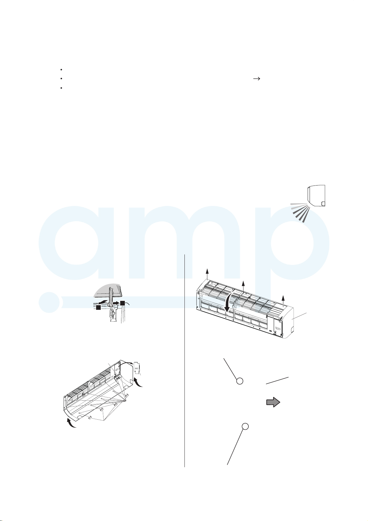
8-1-1. Front panel, control box cover removal
(1) Open the intake grille. While gently pressing the left and
right mounting shafts of the intake grille outward “a”,
remove the intake grille in the direction of the arrow “b”.
Intake grill removal
b
(2) Remove 4 caps.
(3) Remove wire cover screw, then remove the wire cover.
(4) Remove 10 screws.
Wire cover screw
a
Wire cover
Screws
(10 places)
(5) Pull the front panel forward raising the upper surface, to
remove the front panel.
Front
panel
(6) Remove 2 screws, then remove the control box cover.
Screw
Control box
cover
Caps (4 places)
Screw
01-27
Page 30

8-1-2. Install the terminal block
CAUTION
AMP Air Conditioning
www.ampair.co.uk | sales@ampair.co.uk
(1) Attach the terminal block to the indoor unit firmly with 1 screw.
(2) Place the wiring as per the figure.
(Front view)
Screw
Place the wires from the terminal
block under the other wires.
Terminal block (with wire)
Indoor unit main PCB
(Rightside view)
Place wire under the tab.
(3) Connect the wires from the terminal block to the indoor unit main PCB by inserting to connector (CN12).
(4) Change the DIP switch setting as shown in the following photograph.
(Indoor unit main PCB)
Connector (CN12)
Terminal block
wires
• Be careful not to damage the parts on the board. Otherwise, it will cause malfunction.
• Ensure that the connector is properly inserted. Otherwise, it may result in erroneous operation.
2WIRE/3WIRE
01-28
Page 31

8-1-3. Connecting the cable
CAUTION
AMP Air Conditioning
www.ampair.co.uk | sales@ampair.co.uk
(1) Use the following cables (locally purchased) for this connection.
Cable size Remarks
22AWG Sheathed PVC
cable Polar 3 core
(2) Attach the cable to the terminal block.
Position the wires so that the number on the terminal match.
(3) Install the cable as shown in the photograph below.
Be sure to place the wiring under the tabs.
(4) Fix the cable with the cable clamper and screw as shown in the photograph mentioned above.
(Front view)
Red
White
Black
Use shielded cable in
accordance with local
rules for cable.
(Right view)
Cable clamper and screw
Tab
• Do not connect the cable to the terminal for power supply.
• Make sure to insulate the connecting parts when extending the cable.
8-1-4. Front panel, control box cover replacement
Reinstall by reversing the procedure in “8-1-1 Front panel, control box cover removal”
(1) Replace the control box cover (2 screws).
Screw
Screw
Top holes (3 places)
(2) Open a hole in the front panel for the remote
controller cable to pass through.
* Choose from 4 knockout holes marked on
the inside of the front panel.
(3) Replace the front cover.
First, insert the hook on the lower part of the
front panel (5 places), then fit the hooks on
the top (3 places).
(4) Replace the 10 screws.
(5) Replace the wire cover (1 screw).
(6) Replace the 4 caps.
(7) Replace the intake grille.
Indoor unit
Middle hooks
(5 places)
Cut
Knockout holes
Cable
Knockout holes
Front panel
Intake grill installation
Front panel
Middle hooks
(5 places)
Top hooks
(3 places)
c
Press down on 4 places.
01-29
Page 32

8-2 Function setting procedure
AMP Air Conditioning
www.ampair.co.uk | sales@ampair.co.uk
Before activating server room control, assignment of primary unit and secondary unit is required
Change the setting of function setting 96 as follows:
1. Turn on the power source of 2 indoor units.
2. Set one of the indoor unit as “Primary unit” (Setting value: 01) by function setting 96. (For
contents of function setting 96, refer to the Technical manual)
When performing the setting, operate the remote controller close to the signal receiver on the
primary unit as possible so that the signal transmission is firmly received by the primary unit only.
3. Set the other unit as “Secondary unit” (Setting value: 02) by function setting 96.
When performing the setting, operate the remote controller close to the signal receiver on the
secondary unit as possible so that the signal transmission is firmly received by the secondary
unit only.
4. Turn off the power supply of the 2 indoor units.
8-3 Starting units operation
After the setting change on function setting 96 is completed, do as follows:
1. After 30 seconds or more since the power source is turned off, turn on the power source of the
secondary unit.
2. Turn on the power source of the primary unit.
3. Press the MANUAL AUTO button on the primary unit for more than 3 seconds.
You will hear a short beep, and the primary unit starts operation.
NOTE: While performing these steps, error indications will be lit on the unit. Nevertheless,
continue the procedure.
8-4 Starting Server room control
Set the weekly timer on the primary unit.
Example of setting: Monday_0:00_ON - Thursday_12:00_OFF
Primaly unit: Operation start on Monday_0:00 --> Operation stop on Thursday_12:00
Secondary unit: Operation start on Thursday_12:00 --> Operation stop on Monday_0:00
(For the weekly timer setting procedure, refer to the OPERATION MANUAL)
Server room control is activated, and the unit will start the alternative operation.
NOTE: If the alternative operation does not start or error indications on the unit are still lit, reconfirm
whether the settings on function setting 96 are set correctly, and perform the setup procedures
from the beginning.
As for the display pattern of the error indications of the indoor unit, refer to 2-1 ERROR DISPLAY.
9 Canceling procedure of Server room control
Step 1. Turn OFF both system
Step 2. Disconeect the indoor unit communication cable
Step 3. Turn ON both system
Step 4. Change the Fuction setting 96 to 00 both system
After the Indoor units stopped, apply the function setting.
The Indoor units shows Error 12, until the new setting is completed.
Step 5. Turn OFF both system.
*When the Indoor unit shows Error, repeat from the step 3.
*When the Indoor units start the operation, push MANUAL AUTO button more than 3 sec.
01-30
Page 33

WALL MOUNTED type
AMP Air Conditioning
www.ampair.co.uk | sales@ampair.co.uk
INVERTER
2 . TROUBLE SHOOTING
Page 34

2-1 ERROR DISPLAY
AMP Air Conditioning
www.ampair.co.uk | sales@ampair.co.uk
2-1-1 INDOOR UNIT AND WIRED REMOTE CONTROLLER DISPLAY
Please refer the flashing pattern as follows.
Indoor Unit : 30,36LMTA
The OPERATION, TIMER, ECONOMY lamps operate as follows according to the error contents.
Indoor Unit Display
Error Contents
Operation
(Green)
Timer
(Orange)
Serial Communication Error
Wired Remote Controller communication
Error
Server room control communication error
External communication Error 18
Combination Error
Address setting Error in Wired remote
controller system
Connection unit number Error
(Indoor unit Wired remote controller error)
Indoor Unit Model Information Error
EEPROM Access Abnormal
Manual Auto Switch Error
1
times
1 times 2 times
1 times
2 times
2 times
2 times
3 times
3 times
2 times
8 times
3 times
6 times
9 times
2 times
5 times
Economy
(Green)
Continuous1 times1 times
Continuous
Continuous
Continuous
Continuous
Continuous
Continuous
Continuous
Continuous
Wired Remote
Controller
Display
11
12
23
32
35
Trouble
shooting
1,2
3
312
4
5
626
729
8
9
Indoor unit (Communication circuit)
Wired remote controller Error
Indoor Room Thermistor Error
Indoor Heat Ex. Thermistor Error
Human sensor Error
Indoor Unit Fan Motor Error
Drain pump Error
Outdoor unit main PCB model information
Error
Inverter Error
A. F. Voltage Error
IPM Error
3 times 10times
4 times
4 times
4 times
5 times
6 times
6 times
6 times
1 times
2 times
4 times
1 times5 times
3 times
2 times
3 times
Continuous
Continuous
Continuous
Continuous
Continuous
Continuous
Continuous
Continuous
Continuous4 times
Continuous5 times6 times
41
42
44
51
53
62
63
64
65
103A
11
12
13
14
15
16
17
18
19
Discharge Thermistor Error
Compressor Thermistor Error
Heat Ex. Liquid Outlet
Thermistor Error
7 times
7 times
7 times
02-01
1 times
2 times
3 times
Continuous
Continuous
Continuous
71
72
73
20
21
22
Page 35

Error Contents
AMP Air Conditioning
www.ampair.co.uk | sales@ampair.co.uk
Operation
(Green)
Indoor Unit Display
Timer
(Orange)
Economy
(Green)
Wired Remote
Controller
Display
Trouble
shooting
Outdoor Thermistor Error 23
Heat sink temp. sensor Error
Current Sensor Error
High Pressure Switch Error
Over Current Error
Compressor Control Error
Outdoor Unit Fan Motor Error
4 Way Valve Error
Discharge Temp. Error
Compressor Temp. Error
7 times
7 times
8 times
8 times
9 times
9 times
9 times
9 times
10 times
10 times
4 times
7 times
4 times
6 times
4 times
5 times
7 times
9 times
1 times
3 times
Continuous
Continuous
Continuous
Continuous
Continuous
Continuous
Continuous
Continuous
Continuous
Continuous
74
77
84
86
94
95
97
99
A1
A3
24
25
26
27
28
29
30
31
32
02-02
Page 36

2-1-2 WIRED REMOTE CONTROLLER DISPLAY (OPTION)
AMP Air Conditioning
www.ampair.co.uk | sales@ampair.co.uk
3-Wire
1 ERROR DETECTION
If you use a wireless remote control,
the lamp onthe photo detector unit will output error codes by way of blinking patterns.
If you use a wired type remote control, error codes will appear on the remote control display.
See the lamp blinking patterns and error codes in the table. An error display is displayed only during running.
Remote control
This is possible only on a wired remote control.
If an error occurs, the following display will be shown.
(“Er” will appear in the set room temperature display.)
2-Wire
1. Check the error
1. If an error occurs, an error icon appears on the “Monitor mode screen”.
Touch the [Status] on the “Monitor mode screen”.The “Status” screen is displayed.
2. Touch the [Error Information] on the “Status”screen. The “Error Information”screen is displayed.
(If there are no errors, the [Error Information] will not be displayed.)
3. 2-digit numbers correspond to the error code in the table below. Touch the [Next page]
(or [Previous page]) to switch to other connected indoor units.
1. 2. 3.
Mode Set Temp.
!
Status
Fri 10:00AM
Fan
Menu
Status
Air Flow Direction
VT
[ 1 ]
Individual
[ ]
Economy
[ Off ]
Monitor Back
Next
Page
Page 1/ 4
Error
Information
Error Information
Address
[ 02 01 ]
Error Code
[ 14 . 15, 41 . 44 ]
Page 1/ 5
Next
Page
For the details of the indoor unit or outdoor unit error , refer to the error codes in each installation manual
02-03
Page 37

2-2 TROUBLE SHOOTING WITH ERROR CODE
AMP Air Conditioning
www.ampair.co.uk | sales@ampair.co.uk
Trouble shooting 1
OUTDOOR UNIT Error Method:
Serial Communication Error
Indicate or Display:
Indoor Unit :
Operation lamp: 1 time Flash,
Timer lamp : 1 time Flash
Wired Remote Controller :
ERROR CODE : [E : 11]
(Serial Reverse Transfer Error)
Detective Actuators: Detective details:
Outdoor unit Main PCB
Outdoor unit Fan motor
When the indoor unit cannot receive the serial signal from Outdoor unit
more than 2minutes after power ON, or the indoor unit cannot receive
the serial signal more than 15seconds during normal operation.
Forecast of Cause:
1. Connection failure 2. External cause 3. Main PCB failure 4. Active filter module failure
5. Transistor PCB (IPM) failure 6. Filter PCB failure 7. Outdoor unit Fan motor failure
Check Point 1-1 : Reset the power and operate
Does error indication reappear?
NO
YESYES
Check Point 2 : Check connection
Check Point 1-2 : Check external cause such as noise
Check any loose or removed connection line of
between indoor unit and outdoor unit.
>> If there is an abnormal condition, correct it by
referring to Installation Manual or Data &
Technical Manual.
Check connection condition in control unit.
(If there is loose connector, open cable or mis-wiring)
Check if the ground connection is proper.
Check if there is any equipment that causes harmonic wave
near the power cable (Neon light bulb or any electronic
equipment which causes harmonic wave).
OK
Check Point 3 : Check the voltage of power supply
Check the voltage of power supply
>> Check if AC216V(AC240V-10%) - 264V(AC240V+10%) appears
at outdoor unit terminal L - N.
OK
Check Point 4 : Check serial signal (Reverse transfer signal)
Check serial signal (Reverse transfer signal)
>> Check if indicated value swings between AC90V and AC270V at outdoor unit terminal 1 - 3.
>> If it is abnormal, Check the parts as follows.
- Outdoor unit fan motor (PARTS INFORMATION 5)
- Active filter module (PARTS INFORMATION 6)
- Transistor PCB (IPM) (PARTS INFORMATION 7)
- Filter PCB (Check the wire of CN110)
>> If Outdoor fan motor is abnormal, replace Outdoor unit fan motor and Main PCB.
>> If Active filter module or IPM is abnormal, replace it.
>> If the parts are normal, replace Main PCB.
BLACK
WHITE
RED
BLACK
WHITE
1
2
3
L
N
+
-
02-04
Page 38

Trouble shooting 2
AMP Air Conditioning
www.ampair.co.uk | sales@ampair.co.uk
INDOOR UNIT Error Method:
Serial Communication Error
(Serial Forward Transfer Error)
Indicate or Display:
Indoor Unit :
Operation lamp: 1 time Flash,
Timer lamp : 1 time Flash
Wired Remote Controller :
ERROR CODE : [E : 11]
Detective Actuators: Detective details:
Indoor unit Controller PCB
Indoor unit Fan motor
When the outdoor unit cannot properly receive the serial signal from
indoor unit for 10 seconds or more.
Outdoor unit Main PCB
Forecast of Cause:
1. Connection failure 2. External cause 3. Controller PCB failure 4. Indoor unit fan motor failure
5. Outdoor unit Main PCB
Check Point 1-1 : Reset the power and operate
Does error indication reappear?
NO
YESYES
Check Point 2 : Check connection
Check any loose or removed connection line of
between indoor unit and outdoor unit.
>> If there is an abnormal condition, correct it by
referring to Installation Manual or Data &
Technical Manual.
Check connection condition in control unit.
(If there is loose connector, open cable or mis-wiring)
Check Point 1-2 : Check external cause such as noise
Check if the ground connection is proper.
Check if there is any equipment that causes harmonic wave
near the power cable (Neon light bulb or any electronic
equipment which causes harmonic wave).
OK
Check Point 3 : Check the voltage of power supply
Check the voltage of power supply
>> Check if AC216V(AC240V-10%) - 264V(AC240V+10%) appears
at outdoor unit terminal L - N.
OK
Check Point 4 : Check serial signal (Forward transfer signal)
Check serial signal (Forward transfer signal)
>> Check if indicated value swings between AC30V and AC130V at outdoor unit terminal 2 - 3.
>> If it is abnormal, replace Controller PCB.
>> If it is abnormal, Check Indoor unit fan motor. (PARTS INFORMATION 4)
>> If Indoor unit fan motor is abnormal, replace Indoor unit fan motor and Controller PCB.
>> If it is abnormal, replace Outdoor unit Main PCB.
BLACK
WHITE
RED
BLACK
WHITE
1
2
3
L
N
+
-
02-05
Page 39

Trouble shooting 3
AMP Air Conditioning
www.ampair.co.uk | sales@ampair.co.uk
INDOOR UNIT Error Method:
Wired Remote Controller
Indicate or Display:
Indoor Unit :
Operation lamp: 1 times Flash,
Timer lamp : 2 times Flash
Communication Error
Detective Actuators: Detective details:
Wired Remote Controller :
ERROR CODE : [E : 12]
Indoor unit Controller PCB
Wired Remote Controller (Option)
When the indoor unit cannot properly receive the signal from
Wired Remote Controller for 1 minute or more.
Forecast of Cause:
1. Connection failure 2. Wired Remote Controller failure 3. Controller PCB failure
Check Point 1 : Check the connection of terminal
Check & correct the followings.
Check the connection of terminal between Wired Remote Controller and indoor unit,
and check if there is a disconnection of the cable.
OKOK
Check Point 2 : Check Wired Remote Controller and Controller PCB
Check Voltage at CN6 (terminal 1-3) of Controller PCB.
(Power supply to Remote Control)
>> If it is DC12V, Remote Control is failure. (Controller PCB is normal) >> Replace Remote Control
>> If it is DC 0V, Controller PCB is failure. (Check Remote Control once again) >> Replace Controller PCB
*When the server room setting is activate:
Forecast of Cause:
1. Connection failure 2. DIP switch wrong setting 3. Function setting wrong setting 4.Controller PCB failure
Check Point 1 : Check the wiring connection
Check if 3 wires on the terminal are corresponding with the same color or number on the each terminals.
OKOK
Check Point 2 : Check DIP switch setting on the Indoor unit PCB
Check if the DIP Switch set with [3wire]
OKOK
Check Point 3 : Check Function setting
Perform the Function setting again
OKOK
Check Point 4 : Check Wired Remote Controller and Controller PCB
Check Voltage at CN6 (terminal 1-3) of Controller PCB.
>> If it is DC 0V, Controller PCB is failure. >> Replace Controller PCB
02-06
Page 40

Trouble shooting 4
AMP Air Conditioning
www.ampair.co.uk | sales@ampair.co.uk
INDOOR UNIT Error Method:
External communication error
Indicate or Display:
Indoor Unit :
Operation lamp: 1 times Flash,
Timer lamp : 8 times Flash
Wired Remote Controller :
ERROR CODE : [E : 18]
Detective Actuators:
External communication error
Detective details:
After receiving a signal from the external I/O PCB,
the same a signal has not been received for 15sec
Forecast of Cause :
1. Connection failure 2.External I/O PCB failure 3.Controller PCB failure
Check Point 1 : Check the connection
Check any loose or removed connection of between the controller PCB to the external I/OPCB
>>If there is an abnormal condition, correct it by refer to installation manual or
the technical manual.
Check the connection condition on the external I/O PCB and the controller PCB
(If there is loose connector, open cable or mis-wiring)
OKOK
Check Point 2: Replace external I/O PCB
If Check Point 1 do not improve the symptom, change External I/O PCB.
OKOK
Check Point 3: Replace Controller PCB
If Check Point 2 do not improve the symptom, change Controller PCB.
02-07
Page 41

Trouble shooting 5
AMP Air Conditioning
www.ampair.co.uk | sales@ampair.co.uk
OUTDOOR UNIT Error Method:
Combination error
Indicate or Display:
Indoor Unit :
Operation lamp: 2 times Flash,
Timer lamp : 3 times Flash
Detective Actuators: Detective details:
Indoor unit
When the outdoor unit type is multi.
Forecast of Cause:
1. The selection of indoor units is incorrect
Check Point 1 : Check the type of indoor unit
Check the type of the connected indoor unit.
>> If abnormal condition is found, correct it.
OK
Check Point 2 : Replace Main PCB
Wired Remote Controller :
ERROR CODE : [E : 23]
If Check Point 1 do not improve the symptom, replace Main PCB of Outdoor unit.
02-08
Page 42

Trouble shooting 6
AMP Air Conditioning
www.ampair.co.uk | sales@ampair.co.uk
INDOOR UNIT Error Method:
Address setting Error in Wired remote
controller system
Indicate or Display:
Indoor Unit :
Operation lamp: 2 times Flash,
Timer lamp : 6 times Flash
Wired Remote Controller :
ERROR CODE : [E : 26]
Detective Actuators:
Wired remote controller ( 2-Wire )
Indoor unit Controller PCB circuit
Forecast of Cause :
1. Wrong wiring of RCgroup 2. Wrong remote address setting 3. Indoor unit controller PCB failure
4. Remote controller failure
Detective details:
When the address number set by auto setting and manual setting are mixed in
one RC group.
When the duplicated address number exists in one RC group.
Check Point 1 : Wire installation
Wrong wire connection in RCgroup (Please refer to the installation manual)
Check Point 2 : Wrong RCgroup setting
The given address number by auto setting (00) and the manual set number (Except 00) were not existing in one RCG.
The remote controller address setting by U.I. were not existing same address.
The duplicated address number is not existing in one RCgroup
Check Point 3 : Check Indoor unit controller PCB
Check if controller PCB damage
Change controller PCB and check the Error after setting remote controller address
02-09
Page 43

Trouble shooting 7
AMP Air Conditioning
www.ampair.co.uk | sales@ampair.co.uk
INDOOR UNIT Error Method:
Connection unit number error (Indoor
unit in Wired remote controller system)
Indicate or Display:
Indoor Unit :
Operation lamp: 2 times Flash,
Timer lamp : 9 times Flash
Wired Remote Controller :
ERROR CODE : [E : 29]
Detective Actuators:
Wired remote controller ( 2-Wire )
Indoor unit Controller PCB circuit
Forecast of Cause :
1. Wrong wiring / Number of I.U, RC in RCgroup 2. Indoor unit controller PCB defective
Detective details:
When the number of connecting indoor units are out of specified rule.
Check Point 1 : Wire installation
Wrong number of connecting indoor unit
Check Point 2 : Check Indoor unit controller PCB
Check if controller PCB damage
Check if controller PCB and check the Error after setting remote controller address
02-10
Page 44

Trouble shooting 8
AMP Air Conditioning
www.ampair.co.uk | sales@ampair.co.uk
INDOOR UNIT Error Method:
Indoor Unit Model Information Error
EEPROM Access Abnormal
Indicate or Display:
Indoor Unit :
Operation lamp: 3 times Flash,
Timer lamp : 2 times Flash
Wired Remote Controller :
ERROR CODE : [E : 32]
Detective Actuators:
Indoor unit Controller PCB
Detective details:
When power is on and there is some below case.
1. When model information of EEPROM is incorrect.
2. When the access to EEPROM failed.
Forecast of Cause:
1. External cause 2. Defective connection of electric components 3. Controller PCB failure
Check Point 1-1 : Reset Power Supply and operate
Does Error indication show again?
YESYES
Check Point 2 :
Check Indoor unit electric components
Check all connectors.
(loose connector or incorrect wiring)
Check any shortage or corrosion on PCB.
NO
Check Point 1-2 :
Check external cause such as noise
Check if the ground connection is proper.
Check if there is any equipment that causes harmonic wave
near the power cable (Neon light bulb or any electronic
equipment which causes harmonic wave).
Check Point 3 : Replace Controller PCB
Change Controller PCB.
Note : EEPROM
EEPROM(Electronically Erasable and
Programmable Read Only Memory) is a nonvolatile memory which keeps memorized
information even if power is turned off. It can
change the contents electronically.
To change the contents, it uses higher
voltage than normal, and it can not change a
partial contents. (Rewriting shall be done
upon erasing the all contents.)
There is a limit in a number of rewriting.
02-11
Page 45

Trouble shooting 9
AMP Air Conditioning
www.ampair.co.uk | sales@ampair.co.uk
INDOOR UNIT Error Method:
Manual Auto Switch Error
Indicate or Display:
Indoor Unit :
Operation lamp: 3 times Flash,
Timer lamp : 5 times Flash
Detective Actuators: Detective details:
Indoor Unit Controller PCB
Indicator PCB
When the Manual Auto Switch becomes ON for consecutive 30 or
more seconds.
Manual Auto Switch
Forecast of Cause :
1. Manual Auto Switch failure 2. Controller PCB and Indicator PCB failure
Check Point 1 : Check the Manual Auto Switch
Check if Manual Auto Switch is kept pressed.
Check ON/OFF switching operation by using a meter.
>> If Manual Auto Switch is disabled (on/off switching), replace it.
OKOK
Check Point 2 : Replace Controller PCB and Indicator PCB
Wired Remote Controller :
ERROR CODE : [E : 35]
If Check Point 1 do not improve the symptom, replace Controller PCB and Indicator PCB
and execute the check operation again.
02-12
Page 46

Trouble shooting 10
AMP Air Conditioning
www.ampair.co.uk | sales@ampair.co.uk
INDOOR UNIT Error Method:
Indoor unit communication circuit
(WRC) error
Indicate or Display:
Indoor Unit :
Operation lamp: 3 times Flash,
Timer lamp : 10 times Flash
Wired Remote Controller :
ERROR CODE : [E : 3A]
Detective Actuators:
Wired remote controller ( 2-Wire )
Indoor unit Controller PCB circuit
Forecast of Cause :
1. Terminal connection abnormal 2. Wired remote controller failure
Detective details:
When the indoor unit(s) detects the configuration of RCG abnormal or
the indoor unit detects lack of primarily -remote controller.
3. Indoor unit controller PCB defective
Check Point 1 : Check the connection of terminal
After turning off the power supply, check & correct the followings
Indoor unit - Check the connection of terminal between remote control and indoor unit, or between Indoor units and
check if there is a disconnection or short of the cable
Check Point 2 , 3:
Check terminal voltage of controller PCB connector CNC01 (Power supply for remote)
If DC12V, Remote control failure (Controller PCB is OK) >>> Replace Remote controller
If DC0V, Controller PCB failure (Remote is OK) >>> Replace Controller PCB
In case of re-installation is done due to removed connector or incorrect wiring,
turn on the power again.
Check Indoor unit controller PCB
TIP setting the remote controller
Depending on the connected remote controller type, following setting is required:
Connected remote controller DIP switch Jumper (JM9)
2-wire-type wired remote controller is connected
3-wire-type wired remote controller is connected
2WIRE/3WIRE
(Factory setting)
2WIRE/3WIRE
2 wire remote controller PCB
If the communication PCB is not conncected, and JM9 is disconnected, 3A error is displyed.
If the communication PCB is conncected, and JM9 is connected, the 2 wire remote controller doesn’t work.
If the DIP switch is 3 wire side, the 2 wire remote controller doesn’t work.
3 wire remote controller PCB
If the DIP switch is 2 wire side, the 3 wire remote controller doesn’t work.
JM9
(Disconnected)
JM9
(Connected)
(Factory setting)
02-13
Page 47

Trouble shooting 11
AMP Air Conditioning
www.ampair.co.uk | sales@ampair.co.uk
INDOOR UNIT Error Method:
Indoor Room Thermistor Error
Indicate or Display:
Indoor Unit :
Operation lamp: 4 times Flash,
Timer lamp : 1 times Flash
Wired Remote Controller :
ERROR CODE : [E : 41]
Detective Actuators:
Indoor unit Controller PCB
Room temperature thermistor
Forecast of Cause :
1. Connector failure connection 2. Thermistor failure 3. Controller PCB failuer
Detective details:
Room temperature thermistor is open or short is detected always.
Check Point 1 : Check connection of Connector
Check if connector is loose orremoved
Check erroneous connection
Check if thermistor cable is open
>>Reset Power when reinstallingdue to removed connector or incorrect wiring.
OK
Check Point 2 : Remove connector and check Thermistor resistance value
Thermistor Characteristics(Rough value)
Temperature (°C )
Resistance value (k )
-10 15 20 25
58.3
-5 10
44.0
0
5
10.012.515.820.225.933.6
Temperature (°C )
If Thermistor is either open or shorted,replace it and reset the power.
30 35
6.58.0
40 45
4.45.3Resistance value (k )
OK
Check Point 3 : Check voltage of Controller PCB (DC5.0V)
Make sure circuit diagram of each indoorunit and check terminal voltage at Thermistor (DC5.0V)
1
1
2
CN1
If the voltage does not appear, replace Controller PCB and execute the check operation again.
2
3
3
4
4
BLACK
BLACK
BLACK
BLACK
Thermistor( Pipe temp.)
Thermistor( Room Temp.)
DC
02-14
Page 48

Trouble shooting 12
AMP Air Conditioning
www.ampair.co.uk | sales@ampair.co.uk
INDOOR UNIT Error Method:
Indoor Heat Ex. Thermistor Error
Indicate or Display:
Indoor Unit :
Operation lamp: 4 times Flash,
Timer lamp : 2 times Flash
Wired Remote Controller :
ERROR CODE : [E : 42]
Detective Actuators:
Indoor unit Controller PCB
Heat exchanger (MID) Thermistor
Forecast of Cause :
1. Connector failure connection 2. Thermistor failure 3. Controller PCB failuer
Detective details:
Heat exchanger (MID) thermistor is open or short is detected always.
Check Point 1 : Check connection of Connector
Check if connector is loose or removed
Check erroneous connection
Check if thermistor cable is open
>>Reset Power when reinstalling due to removed connector or incorrectwiring.
OK
Check Point 2 : Remove connector and check Thermistor resistance value
Thermistor Characteristics(Rough value)
Temperature (°C )
Resistance value (k )
Temperature (°C )
-30
1131.9
-25
804.5
-20
579.6
20 25 30 35
-15
422.9
-10
312.3
-5 15
233.2
40 45 50
0
5 10
80.3103.3134.2176.0
55
63
31.739.649.762.9
If Thermistor is either open or shorted,replace it and reset the power.
OK
Check Point 3 : Check voltage of Controller PCB (DC5.0V)
Make surecircuit diagram of eachindoor unit and check terminal voltage at Thermistor(DC5.0V)
1
1
2
CN1
If the voltage does not appear, replace Controller PCB andexecute the check operation again.
2
3
3
4
4
BLACK
BLACK
BLACK
BLACK
Thermistor ( Pipe temp.)
Thermistor ( Room Temp.)
17.120.925.6Resistance value (k )
14.1
11.66010.4
DC
02-15
Page 49

Trouble shooting 13
AMP Air Conditioning
www.ampair.co.uk | sales@ampair.co.uk
INDOOR UNIT Error Method:
Human sensor error
Indicate or Display:
Indoor Unit :
Operation lamp: 4 times Flash,
Timer lamp : 4 times Flash
Wired Remote Controller :
ERROR CODE : [E : 44]
Detective Actuators:
Indoor unit Main PCB
Detective details:
1 Detect the open condition of the sensor.
2 When the signal from the sensor is "L"(=0V) for more than 10 min.
Forecast of Cause:
2. Sensor failure1. Connection failure 3. Indoor unit Main PCB failure
Check Point 1 : Check the connector connection and cable open
Check if connector is loose or removed
Check erroneous connection
Check if sensor cable is open
>>Reset Power when reinstalling due to removed connector or incorrect wiring.
OK (Sensor connections error) OK(Sensor signal error)
Check Point 2 : Conduction check
Disconnect the sensor and check the 2-3pin
on sensor connector.
>>With conduction : Main PCB failure
>>Without conduction : Sensor failure
Check Point 2 : Voltage check
Disconnect the sensor and check the Voltage
of 1pin of the CN10 on the Main PCB
>>5V: Sensor failure
>>Other than 5V: Main PCB failure
02-16
Page 50

Trouble shooting 14
AMP Air Conditioning
www.ampair.co.uk | sales@ampair.co.uk
INDOOR UNIT Error Method:
Indoor unit Fan Motor Error
Indicate or Display:
Indoor Unit :
Operation lamp: 5 times Flash,
Timer lamp : 1 times Flash
Wired Remote Controller :
ERROR CODE : [E : 51]
Detective Actuators:
Indoor unit Controller PCB
Indoor unit fan motor
Detective details:
When the condition that actual frequency of Indoor Fan is
below 1/3 of target frequency is continued more than 56 seconds.
Forecast of Cause:
1. Fan rotation failure 2. Fan motor winding open 3. Motor protection by surrounding temperature rise
4. Control PCB failure 5. Indoor unit fan motor failure
Check Point 1 : Check rotation of Fan
Rotate the fan by hand when operation is off.
(Check if fan is caught, dropped off or locked motor)
>>If Fan or Bearing is abnormal, replace it.
OK
Check Point 2 : Check ambient temp. around motor
Check excessively high temperature around the motor.
(If there is any surrounding equipment that causes heat)
>>Upon the temperature coming down, restart operation.
OK
Check Point 3 : Check Indoor unit fan motor
Check Indoor unit fan motor. (PARTS INFORMATION 4)
>>If Indoor unit fan motor is abnormal, replace Indoor unit fan motor.
OK
Check Point 4 : Replace Controller PCB
If Check Point 1- 3 do not improve the symptom, replace Controller PCB.
02-17
Page 51

Trouble shooting 15
AMP Air Conditioning
www.ampair.co.uk | sales@ampair.co.uk
INDOOR UNIT Error Method:
Drain pump error
Indicate or Display:
Indoor Unit :
Operation lamp: 5 times Flash,
Timer lamp : 3 times Flash
Wired Remote Controller :
ERROR CODE : [E : 53]
Detective Actuators:
Indoor Unit Controller PCB Circuit
Float Switch
Forecast of Cause : 1. Controller PCB failure
Detective details:
When Float switch is ON for more than 3 minutes.
Check Point 1 : Replacethe indoor unit controller PCB
No float switch on this unit
If this error is displayed, Replease the indoor unit controller PCB.
02-18
Page 52

Trouble shooting 16
AMP Air Conditioning
www.ampair.co.uk | sales@ampair.co.uk
OUTDOOR UNIT Error Method:
Outdoor unit main PCB model
information error
Indicate or Display:
Indoor Unit :
Operation lamp: 6 times Flash,
Timer lamp : 2 times Flash
Detective Actuators: Detective details:
Outdoor unit Main PCB
Access to EEPROM failed due to some cause after outdoor unit started.
Forecast of Cause:
1. External cause (Noise, temporary open, voltage drop) 2. Main PCB failure
Wired Remote Controller :
ERROR CODE : [E : 62]
Check Point 1-1 : Reset Power Supply and operate
Does Error indication show again?
YESYES
Check Point 2 : Replace Main PCB
Change Main PCB.
NO
Check Point 1-2 : Check external cause
Check if temporary voltage drop was not generated.
Check if momentary open was not generated.
Check if ground is connection correctly or there are no related
cables near the power line.
02-19
Page 53
Trouble shooting 17
AMP Air Conditioning
www.ampair.co.uk | sales@ampair.co.uk
OUTDOOR UNIT Error Method:
Inverter Error
Indicate or Display:
Indoor Unit :
Operation lamp: 6 times Flash,
Timer lamp : 3 times Flash
Detective Actuators: Detective details:
Wired Remote Controller :
ERROR CODE : [E : 63]
Inverter PCB
Forecast of Cause :
1. External cause. 2. Power supply to Filter PCB to Inverter PCB wiring disconnection, open
3. Filter PCB failure 4. Inverter PCB failure
Check Point 1-1 :
Turn the power on again?
Error displayed again?
NO
Error information received from Inverter PCB
Check Point 1-2 : External cause
Check if temporary voltage drop was not generated.
Check if temporary open was not generated.
Check if ground is connected correctly or there are no related cables near the
power line.
YES
Check Point 2 : Check the wiring (Power supply to Filter PCB to Inverter PCB)
Connector and wiring connection state check
Cable open check
OK
Check Point 3 : Replace Filter PCB (INV) and Inverter PCB
Replace Filter PCB and Inverter PCB.
02-20
Page 54

Trouble shooting 18
AMP Air Conditioning
www.ampair.co.uk | sales@ampair.co.uk
OUTDOOR UNIT Error Method:
Active filter voltage error
Indicate or Display:
Indoor Unit :
Operation lamp: 6 times Flash,
Timer lamp : 4 times Flash
Wired Remote Controller :
ERROR CODE : [E : 64]
Detective Actuators:
Outdoor unit Main PCB
Active filter module
Detective details:
When inverter input DC voltage is higher than 430V or
lower than 110V.
When a momentary power cut off occurred on low voltage
Forecast of Cause :
1. External cause 2. Connector connection failure 3. Main PCB failure 4. Active filter module failure
Check Point 1 : Check external cause at Indoor and Outdoor (Voltage drop or Noise)
Instant drop : Check if there is a large load electric apparatus in the same circuit.
Momentary power failure : Check if there is a defective contact or leak current
in the power supply circuit.
Noise : Check if there is any equipment causing harmonic wave near electric line.
(Neon bulb or electric equipment that may cause harmonic wave)
Check the complete insulation of grounding.
OKOK
Check Point 2 : Check connection of Connector
Check if connector is removed.
Check erroneous connection.
Check if cable is open.
>>Upon correcting the removed connector or mis-wiring, reset the power.
OKOK
Check Point 3 : Check Active filter module
Check Active filter module.
>>If Active filter module is abnormal, replace it. (PARTS INFORMATION 6)
OKOK
Check Point 4 : Replace Main PCB
If Check Point 1 - 3 do not improve the symptom, change Main PCB.
02-21
Page 55

Trouble shooting 19
AMP Air Conditioning
www.ampair.co.uk | sales@ampair.co.uk
OUTDOOR UNIT Error Method:
IPM Error
Indicate or Display:
Indoor Unit :
Operation lamp: 6 times Flash,
Timer lamp : 5 times Flash
Wired Remote Controller :
ERROR CODE : [E : 65]
Detective Actuators:
Outdoor unit Main PCB
Compressor
Detective details:
When more than normal operating current to IPM in Main PCB flows,
the compressor stops.
After the compressor restarts, if the same operation is repeated within 40sec,
the compressor stops again.
If and repeats 5 times, the compressor stops permanently.
Forecast of Cause :
1. Defective connection of electric components 2. Outdoor Fan Operation failure
3. Outdoor Heat Exchanger clogged 4. Compressor failure 5. Transistor PCB failure
6. Main PCB failure
Check Point 1 : Check connections of Outdoor Unit Electrical Components
Check if the terminal connection is loose.
Check if connector is removed.
Check erroneous connection.
Check if cable is open.
>>Upon correcting the removed connector or mis-wiring, reset the power.
OK
Check Point 2 : Check Outdoor Fan, Heat Exchanger
Is there anything obstructing the air distribution circuit?
Is there any clogging of Outdoor Heat Exchanger?
Is the Fan rotating by hand when operation is off ?
>> If the Fan Motor is locked, replace it.
OK
Check Point 3 : Check Outdoor Fan
Check Outdoor Fan Motor. (Refer to Trouble shooting 29)
>> If the Fan Motor is failure, replace it.
OK
Check Point 4 : Check Compressor
Check Compressor.
(PARTS INFORMATION 2)
OK
Check Point 5 : Check Transistor PCB
Transistor PCB.
Check
(PARTS INFORMATION 7)
OKOK
Check Point 6 : Replace Main PCB
If Check Point 1 5 do not improve the symptom, change Main PCB.
02-22
Page 56

Trouble shooting 20
AMP Air Conditioning
www.ampair.co.uk | sales@ampair.co.uk
OUTDOOR UNIT Error Method:
Indicate or Display:
Indoor Unit :
Operation lamp: 7 times Flash,
Discharge Thermistor Error
Timer lamp : 1 times Flash
Detective Actuators: Detective details:
Outdoor unit Main PCB
Discharge pipe temperature thermistor
When Discharge pipe temperature thermistor open or short-circuit
is detected at power ON or while running the compressor.
Forecast of Cause :
1. Connector connection failure 2. Thermistor failure 3. Main PCB failure
Check Point 1 : Check connection of connector
Check if connector is removed.
Check if connector is erroneous connection.
Check if thermistor cable is open.
>> Upon correcting the removed connector or mis-wiring, reset the power.
OKOK
Check Point 2 : Remove connector and check thermistor resistance value
Wired Remote Controller :
ERROR CODE : [E : 71]
Thermistor characteristics (Approx. value)
-30
1013.1
-20
531.6
-10
292.9
-5 50Temperature (°C )
221.1
30 04 05 60
40.0
17.826.3
12.3
If Thermistor is either open or shorted, replace it and reset the power.
OKOK
Check Point 3 : Check voltage of Main PCB (DC5.0V)
Make sure circuit diagram of outdoor unit and check terminal voltage at thermistor (DC5.0V)
Thermistor
(Compressor temp.)
BROWN
3
3
2
2
CN64
CN62
CN65
CN63
BROWN
1
1
Thermistor
(Outdoor temp.)
BLUE
3
3
2
2
BLUE
1
1
Thermistor
(Heat exchanger)
BLACK
3
3
2
2
BLACK
1
1
Thermistor
(Discharge pipe)
BROWN
3
3
2
2
BROWN
1
1
01 51
20
62.679.1100.9129.8168.6Resistance value (k )
12010007 08 09Temperature (°C )
2.03.44.66.38.7Resistance value (k )
If the voltage does not appear, replace Main PCB.
02-23
Page 57

Trouble shooting 21
AMP Air Conditioning
www.ampair.co.uk | sales@ampair.co.uk
OUTDOOR UNIT Error Method:
Compressor Thermistor Error
Indicate or Display:
Indoor Unit :
Operation lamp: 7 times Flash,
Timer lamp : 2 times Flash
Detective Actuators: Detective details:
Outdoor unit Main PCB
Compressor temperature thermistor
When Compressor temperature thermistor open or short-circuit
is detected at power ON or while running the compressor.
Forecast of Cause :
1. Connector connection failure 2. Thermistor failure 3. Main PCB failure
Check Point 1 : Check connection of connector
Check if connector is removed.
Check if connector is erroneous connection.
Check if thermistor cable is open.
>> Upon correcting the removed connector or mis-wiring, reset the power.
OKOK
Check Point 2 : Remove connector and check thermistor resistance value
Wired Remote Controller :
ERROR CODE : [E : 72]
Thermistor characteristics (Approx. value)
-30
1013.1
-20
531.6
-10
292.9
-5 5 0Temperature (°C )
221.1
30 04 05 60
40.0
17.826.3
12.3
If Thermistor is either open or shorted, replace it and reset the power.
OKOK
Check Point 3 : Check voltage of Main PCB (DC5.0V)
Make sure circuit diagram of outdoor unit and check terminal voltage at thermistor (DC5.0V)
Thermistor
(Compressor temp.)
BROWN
3
3
2
2
CN64
CN62
CN65
CN63
BROWN
1
1
Thermistor
(Outdoor temp.)
BLUE
3
3
2
2
BLUE
1
1
Thermistor
(Heat exchanger)
BLACK
3
3
2
2
BLACK
1
1
Thermistor
(Discharge pipe)
BROWN
3
3
2
2
BROWN
1
1
01 51
20
62.679.1100.9129.8168.6Resistance value (k )
12010007 08 09Temperature (°C )
2.03.44.66.38.7Resistance value (k )
If the voltage does not appear, replace Main PCB.
02-24
Page 58

Trouble shooting 22
AMP Air Conditioning
www.ampair.co.uk | sales@ampair.co.uk
OUTDOOR UNIT Error Method:
Heat Ex. Liquid Outlet Thermistor Error
Indicate or Display:
Indoor Unit :
Operation lamp: 7 times Flash,
Timer lamp : 3 times Flash
Detective Actuators: Detective details:
Wired Remote Controller :
ERROR CODE : [E : 73]
Outdoor unit Main PCB
Heat exchanger temperature thermistor
When Heat exchanger temperature thermistor open or
short-circuit is detected at power ON or while running the compressor.
Forecast of Cause :
1. Connector connection failure 2. Thermistor failure 3. Main PCB failure
Check Point 1 : Check connection of connector
Check if connector is removed.
Check if connector is erroneous connection.
Check if thermistor cable is open.
>> Upon correcting the removed connector or mis-wiring, reset the power.
OKOK
Check Point 2 : Remove connector and check thermistor resistance value
Thermistor characteristics (Approx. value)
-30Temperature (°C )
92.3
20Temperature (°C )
5- 0-10-20
70
5
10 15
9.712.416.120.927.549.2Resistance value (k )
7.7
80
9003 04 05 06
6.1
0.91.31.82.64.0Resistance value (k )
0.7
If Thermistor is either open or shorted, replace it and reset the power.
OKOK
Check Point 3 : Check voltage of Main PCB (DC5.0V)
Make sure circuit diagram of outdoor unit and check terminal voltage at thermistor (DC5.0V)
Thermistor
(Compressor temp.)
BROWN
3
3
2
2
CN64
CN62
CN65
CN63
BROWN
1
1
Thermistor
(Outdoor temp.)
BLUE
3
3
2
2
BLUE
1
1
Thermistor
(Heat exchanger)
BLACK
3
3
2
2
BLACK
1
1
Thermistor
(Discharge pipe)
BROWN
3
3
2
2
BROWN
1
1
0.5
If the voltage does not appear, replace Main PCB.
02-25
Page 59

Trouble shooting 23
AMP Air Conditioning
www.ampair.co.uk | sales@ampair.co.uk
OUTDOOR UNIT Error Method:
Outdoor Thermistor Error
Indicate or Display:
Indoor Unit :
Operation lamp: 7 times Flash,
Timer lamp : 4 times Flash
Detective Actuators: Detective details:
Outdoor unit Main PCB
Outdoor temperature thermistor
When Outdoor temperature thermistor open or short-circuit
is detected at power ON or while running the compressor.
Forecast of Cause :
1. Connector connection failure 2. Thermistor failure 3. Main PCB failure
Check Point 1 : Check connection of connector
Check if connector is removed.
Check if connector is erroneous connection.
Check if thermistor cable is open.
>> Upon correcting the removed connector or mis-wiring, reset the power.
OKOK
Check Point 2 : Remove connector and check thermistor resistance value
Wired Remote Controller :
ERROR CODE : [E : 74]
Thermistor characteristics (Approx. value)
70
1.72.43.55.28.0Resistance value (k )
5
10 15
20.726.935.246.662.3115.2Resistance value (k )
8003 04 05 06
1.2
-30Temperature (°C )
224.3
20Temperature (°C )
12.6
5- 0-10-20
If Thermistor is either open or shorted, replace it and reset the power.
OKOK
Check Point 3 : Check voltage of Main PCB (DC5.0V)
Make sure circuit diagram of outdoor unit and check terminal voltage at thermistor (DC5.0V)
Thermistor
(Compressor temp.)
BROWN
3
3
2
2
CN64
CN62
CN65
CN63
BROWN
1
1
Thermistor
(Outdoor temp.)
BLUE
3
3
2
2
BLUE
1
1
Thermistor
(Heat exchanger)
BLACK
3
3
2
2
BLACK
1
1
Thermistor
(Discharge pipe)
BROWN
3
3
2
2
BROWN
1
1
16.1
If the voltage does not appear, replace Main PCB.
02-26
Page 60

Trouble shooting 24
AMP Air Conditioning
www.ampair.co.uk | sales@ampair.co.uk
OUTDOOR UNIT Error Method:
Heat Sink Thermistor Error
Indicate or Display:
Indoor Unit :
Operation lamp: 7 times Flash,
Timer lamp : 7 times Flash
Wired Remote Controller :
ERROR CODE : [E : 77]
Detective Actuators:
Inverter PCB
Forecast of Cause :
Detective details:
Heat sink temperature thermistor (Built-in IPM) open/short detected
1. Inverter PCB failure
If this error is displayed, replace Inverter PCB
02-27
Page 61
Trouble shooting 25
AMP Air Conditioning
www.ampair.co.uk | sales@ampair.co.uk
OUTDOOR UNIT Error Method:
Current Sensor Error
Indicate or Display:
Indoor Unit :
Operation lamp: 8 times Flash,
Timer lamp : 4 times Flash
Wired Remote Controller :
ERROR CODE : [E : 84]
Detective Actuators:
Outdoor unit Main PCB
Detective details:
When Input Current Sensor has detected 0A, while Inverter Compressor is
operating at higher than 56rps,
after 1minute upon starting the Compressor. (Except during the defrost operation)
Forecast of Cause :
1. Defective connection of electric components 2. External cause 3. Main PCB failure
Check Point 1-1 : Reset Power Supply and operate
Does Error indication show again?
NO
YES
Check Point 2 :
Check connections of Outdoor Unit Electrical Components
Check if the terminal connection is loose.
Check if connector is removed.
Check erroneous connection.
Check if cable is open.
>>Upon correcting the removed connector or mis-wiring,
reset the power.
OK
Check Point 1-2 :
Check external cause at Indoor and Outdoor
(Voltage drop or Noise)
Instant drop : Check if there is a large load electric
apparatus in the same circuit.
Momentary power failure : Check if there is a defective
contact or leak current in the
power supply circuit.
Noise : Check if there is any equipment causing harmonic
wave near electric line.(Neon bulb or electric
equipment that may cause harmonic wave)
Check the complete insulation of grounding.
Check Point 4 : Replace Main PCB
If Check Point 1, 2 do not improve the symptom, change Main PCB.
02-28
Page 62
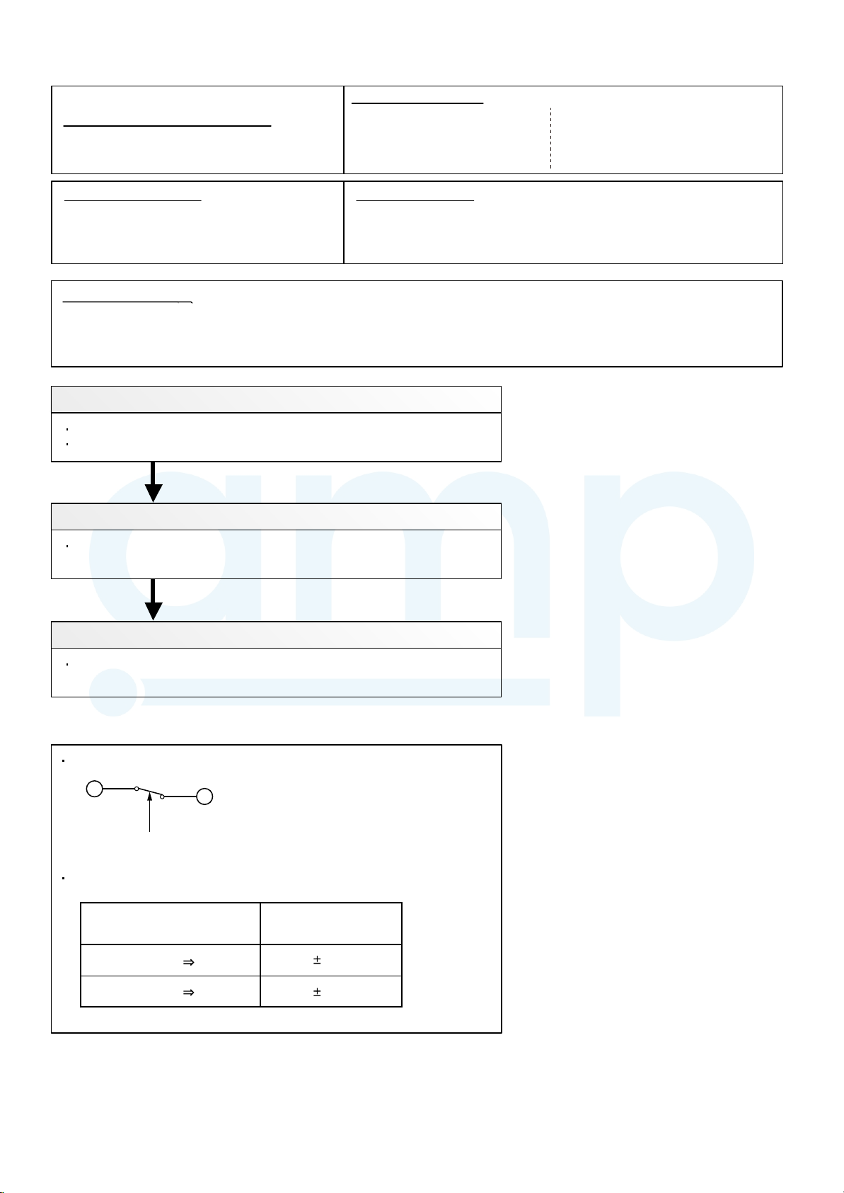
Trouble shooting 26
AMP Air Conditioning
www.ampair.co.uk | sales@ampair.co.uk
OUTDOOR UNIT Error Method:
High Pressure Switch Error
Indicate or Display:
Indoor Unit :
Operation lamp: 8 times Flash,
Timer lamp : 6 times Flash
Detective Actuators: Detective details:
Outdoor unit Main PCB
High Pressure Switch
When pressure switch open is detected in 10 seconds
after the power is turned on.
Forecast of Cause :
1. High pressure switch connector disconnection, open
2. High pressure switch characteristics failure
3. Main PCB failure
Check Point 1 : Check the high pressure switch connection state
Connector and wiring connection state check
Cable open check
OK
Wired Remote Controller :
ERROR CODE : [E : 86]
Check Point 2 : Check the high pressure switch characteristics
Switch characteristics check
* For the characteristics of high pressure switch, refer to below.
OK
Check Point 3 : Replace Main PCB
Change Main PCB, and execute the check operation again.
Type of contact
C
Pressure
Characteristics of pressure switch
H
(30 : CN90)
(34 : CN101)
Pressure switch 1
Contact : Short Open
Contact : Open Short
4.2 0.1MPa
3.2 0.15MPa
02-29
Page 63
Trouble shooting 27
AMP Air Conditioning
www.ampair.co.uk | sales@ampair.co.uk
OUTDOOR UNIT Error Method:
Over Current Error
Indicate or Display:
Indoor Unit :
Operation lamp: 9 times Flash,
Timer lamp : 4 times Flash
Wired Remote Controller :
ERROR CODE : [E : 94]
Detective Actuators:
Outdoor unit Main PCB
Compressor
Transistor PCB (IPM)
Forecast of Cause :
1. Outdoor unit fan operation defective, foreign matter on hear exchanger,
Detective details:
"Protection stop by overcurrent generation after inverter compressor start
processing completed'' generated consecutively 10 times.
* The number of generations is reset if the start-up of
the compressor succeeds.
excessive rise of ambient temperature
2. Main PCB
3. Inverter compressor failure (lock, winding short)
4. Transistor PCB (IPM) failure
Check Point 1 : Check the outdoor unit fan operation, heat exchanger, ambient temperature
No obstructions in air passages?
Heat exchange fins clogged
Outdoor unit fan motor check
Ambient temperature not raised by the effect of other heat sources?
Discharged air not sucked in?
OKOK
Check Point 2: Check Transistor PCB (IPM)
Check IPM. (PARTS INFORMATION 7)
>> If IPM is abnormal, replace Transistor PCB.
OKOK
Check Point 3: Replace Main PCB
If Check Point 1 or 1,2 do not improve the symptom, change Main PCB.
OKOK
Check Point 4: Replace Compressor
If Check Point 3 do not improve the symptom, change Compressor.
02-30
Page 64

Trouble shooting 28
AMP Air Conditioning
www.ampair.co.uk | sales@ampair.co.uk
OUTDOOR UNIT Error Method:
Compressor Control Error
Indicate or Display:
Indoor Unit :
Operation lamp: 9 times Flash,
Timer lamp : 5 times Flash
Wired Remote Controller :
ERROR CODE : [E : 95]
Detective Actuators:
Outdoor unit Main PCB
Compressor
Transistor PCB (IPM)
Detective details:
While running the compressor, if the detected rotor location is out of
phase with actual rotor location more than 90°,
the compressor stops.
After the compressor restarts, if the same operation is repeated
within 40sec, the compressor stops again.
If and repeats 5 times, the compressor stops permanently.
Forecast of Cause :
1. Defective connection of electric components 2. Main PCB failure 3. Compressor failure
4. Transistor PCB (IPM) failure
Check Point 1 : Check Noise from Compressor
Turn on Power and check operation noise.
If an abnormal noise show, replace Compressor.
OKOK
Check Point 2 : Check connection of around the Compressor components
For Compressor Terminal, Main PCB
Check if connector is removed.
Check erroneous connection.
Check if cable is open.
(Refer to PARTS INFORMATION 2)
>>Upon correcting the removed connector or mis-wiring, reset the power.
OKOK
Check Point 3: Check Transistor PCB (IPM)
Check IPM. (PARTS INFORMATION 7)
>> If IPM is abnormal, replace Transistor PCB.
OKOK
Check Point 4: Replace Main PCB
If Check Point 1,2 or 1 3 do not improve the symptom, change Main PCB.
OKOK
Check Point 5: Replace Compressor
If Check Point 4 do not improve the symptom, change Compressor.
02-31
Page 65

Trouble shooting 29
AMP Air Conditioning
www.ampair.co.uk | sales@ampair.co.uk
OUTDOOR UNIT Error Method:
Outdoor Unit Fan Motor Error
Indicate or Display:
Indoor Unit :
Operation lamp: 9 times Flash,
Timer lamp : 7 times Flash
Wired Remote Controller :
ERROR CODE : [E : 97]
Detective Actuators:
Outdoor unit Main PCB
Outdoor unit fan motor
Detective details:
When outdoor fan rotation speed is less than 100rpm in 20 seconds
after fan motor starts, fan motor stops.
After fan motor restarts, if the same operation within 60sec is repeated
3 times in a row, compressor and fan motor stops.
If and repeats 5 times in a row, compressor and fan motor stops
permanently.
Forecast of Cause:
1. Fan rotation failure 2. Motor protection by surrounding temperature rise 3. Main PCB failure
4. Outdoor unit fan motor failure
Check Point 1 : Check rotation of Fan
Rotate the fan by hand when operation is off.
(Check if fan is caught, dropped off or locked motor)
>>If Fan or Bearing is abnormal, replace it.
OK
Check Point 2 : Check ambient temp. around motor
Check excessively high temperature around the motor.
(If there is any surrounding equipment that causes heat)
>>Upon the temperature coming down, restart operation.
OK
Check Point 3 : Check Outdoor unit fan motor
Check Outdoor unit fan motor. (PARTS INFORMATION 5)
>>If Outdoor Fan Motor is abnormal, replace Outdoor fan motor and Main PCB.
OK
Check Point 4 : Check Output Voltage of Main PCB
Check outdoor unit circuit diagram and the voltage. (Measure at Main PCB side connector)
RED
1
2
3
CN800
Read wire DC voltage
Red - Black
White - Black
4
5
6
7
BLACK
WHITE
YELLOW
BROWN
FAN MOTOR
FM
240 ~ 400V
15 1.5V
If the voltage is not correct, replace Main PCB.
02-32
Page 66

Trouble shooting 30
AMP Air Conditioning
www.ampair.co.uk | sales@ampair.co.uk
OUTDOOR UNIT Error Method:
4-Way Valve Error
Indicate or Display:
Indoor Unit :
Operation lamp: 9 times Flash,
Timer lamp : 9 times Flash
Wired Remote Controller :
ERROR CODE : [E : 99]
Detective Actuators:
Indoor unit Controller PCB
Heat Ex. temperature thermistor
Room temperature thermistor
4-way valve
Detective details:
When the indoor heat exchanger temperature is compared with
the room temperature, and either following condition is detected
continuously two times, the compressor stops.
Cooling or Dry operation
[Indoor heat exchanger temp.] - [Room temp.] > 10degC
Heating operation
[Indoor heat exchanger temp.] - [room temp.] < -10degC
If the same operation is repeated 5 times, the compressor stops permanently.
Forecast of Cause :
1. Air filter clogged 2. Connector connection failure 3. Thermistor failure 4. Coil failure
5. 4-way valve failure 6. Controller PCB failure
Check Point 1 : Check the Air filter condition
Check is Air filter dirty.
>>If the Air filter dirty, clean up the Air filter.
OKOK
Check Point 2 : Check connection of Connector
Check if connector is removed.
Check erroneous connection.
Check if thermistor cable is open.
>> Upon correcting the removed connector or mis-wiring, reset the power.
OKOK
Check Point 3 : Check each thermistor
Isn’t it fallen off the holder?
Is there a cable pinched?
>> Check characteristics of thermistor (Refer to Trouble shooting 11, 12),
If defective, replace the thermistor
OKOK
Check Point 4 : Check the solenoid coil and 4-way valve
[ Solenoid coil ]
Remove CN30 from PCB and check the resistance value of coil.
Resistance value is 2.085 (at 20°C).
>> If it is Open or abnormal resistance value, replace Solenoid Coil.
[ 4-way valve ]
Check each piping temperature,
and the location of the valve by the temperature difference.
>> If the value location is not proper, replace 4-way valve.
OKOK
Check Point 5 : Replace Controller PCB
If Check Point 1- 3 do not improve the symptom, replace Controller PCB.
02-33
Page 67

Trouble shooting 31
AMP Air Conditioning
www.ampair.co.uk | sales@ampair.co.uk
OUTDOOR UNIT Error Method:
Discharge Temp. Error
Indicate or Display:
Indoor Unit :
Operation lamp: 10 times Flash,
Timer lamp : 1 times Flash
Wired Remote Controller :
ERROR CODE : [E : A1]
Detective Actuators:
Detective details:
Discharge temperature thermistor
Outdoor unit Main PCB
Forecast of Cause :
1. 3-way valve not opened 2. EEV defective, strainer clogged
3. Outdoor unit operation failure, foreign matter on heat exchanger
4. Discharge temperature thermistor failure 5. Insufficient refrigerant
6. Main PCB failure
<Cooling operation>
Check Point 1 : Check if 3-way valve(gas side) is open.
If the 3-way valve(gas side) was closed, open the
3-way valve(gas side) and check operation.
OK
Check Point 2 : Check the EEV, strainer
EEV open?
Strainer clogging check
(Refer to PARTS INFORMATION 3)
"Protection stop by "discharge temperature 110degC during compressor
operation"" generated 2 times within 24 hours.
<Heating operation>
Check Point 1 : Check if 3-way valve(liquid side) is open.
If the 3-way valve(liquid side) was closed, open the
3-way valve(liquid side) and check operation.
OK
Check Point 2 : Check the EEV, strainer
EEV open?
Strainer clogging check
(Refer to PARTS INFORMATION 3)
OK
Check Point 3 : Check the outdoor unit fan,heat exchanger
Check for foreign object at heat exchanger
Check if fan can be rotated by hand.
Motor check (PARTS INFORMATION 5)
OK
Check Point 4 : Check the discharge thermistor
Discharger thermistor characteristics check
(Check by disconnecting thermistor from PCB.)
* For the characteristics of the thermistor, refer to the "Trouble shooting 20".
OK
Check Point 5 : Check the refrigerant amount
Leak check
OK
OK
Check Point 6 : Replace Main PCB
If Check Point 1- 5 do not improve the symptom, replace Main PCB.
02-34
Page 68

Trouble shooting 32
AMP Air Conditioning
www.ampair.co.uk | sales@ampair.co.uk
OUTDOOR UNIT Error Method:
Compressor Temp. Error
Indicate or Display:
Indoor Unit :
Operation lamp: 10 times Flash,
Timer lamp : 3 times Flash
Wired Remote Controller :
ERROR CODE : [E : A3]
Detective Actuators:
Detective details:
Compressor temperature thermistor
Outdoor unit Main PCB
Forecast of Cause :
1. 3-way valve not opened 2. EEV defective, strainer clogged
3. Outdoor unit operation failure, foreign matter on heat exchanger
4. Compressor temperature thermistor
6. Main PCB failure
<Cooling operation>
Check Point 1 : Check if 3-way valve(gas side) is open.
If the 3-way valve(gas side) was closed, open the
3-way valve(gas side) and check operation.
OK
Check Point 2 : Check the EEV, strainer
EEV open?
Strainer clogging check
(Refer to PARTS INFORMATION 3)
"Protection stop by
"compressor temperature 108degC(30/ 34) during
compressor operation"" generated 2 times within 24 hours.
failure 5. Insufficient refrigerant
<Heating operation>
Check Point 1 : Check if 3-way valve(liquid side) is open.
If the 3-way valve(liquid side) was closed, open the
3-way valve(liquid side) and check operation.
OK
Check Point 2 : Check the EEV, strainer
EEV open?
Strainer clogging check
(Refer to PARTS INFORMATION 3)
OK
Check Point 3 : Check the outdoor unit fan,heat exchanger
Check for foreign object at heat exchanger
Check if fan can be rotated by hand.
Motor check (PARTS INFORMATION 5)
OK
Check Point 4 : Check the Compressor thermistor
Compressor thermistor characteristics check
(Check by disconnecting thermistor from PCB.)
* For the characteristics of the thermistor,refer to the "Troubleshooting 21".
OK
Check Point 5 : Check the refrigerant amount
Leak check
OK
OK
Check Point 6 : Replace Main PCB
If Check Point 1- 5 do not improve the symptom, replace Main PCB.
02-35
Page 69

2-3 TROUBLE SHOOTING WITH NO ERROR CODE
AMP Air Conditioning
www.ampair.co.uk | sales@ampair.co.uk
Trouble shooting 34
Forecast of Cause:
1. Power Supply failure 2. External cause
Indoor Unit - No Power
3. Electrical Components defective
Check Point 1 : Check Installation Condition
Isn’t the breaker down?
Check loose or removed connection cable.
>>If abnormal condition is found, correct it by referring
to Installation Manual or Data & Technical Manual.
OKOK
Check Point 2 : Check external cause at Indoor and Outdoor (Voltage drop or Noise)
Instant drop ----- Check if there is a large load electric apparatus in the same circuit.
Momentary power failure ----- Check if there is a defective contact or leak current in
the power supply circuit.
Noise ----- Check if there is any equipment causing harmonic wave near electric line.
(Neon bulb or electric equipment that may cause
Check the complete insulation of grounding.
harmonic wave)
OK
Check Point 3 : Check Electrical Components
Check the voltage of power supply.
>> Check if AC216 - 264V appears at Outdoor Unit Terminal L - N.
YESYES
Check Fuse in Filter PCB.
>> If Fuse is open, check if the wiring between Terminal and Filter PCB
is loose, and replace Fuse.
Check Varistor in Filter PCB.
>> If Varistor is defective, there is a possibility of an abnormal power supply.
Check the correct power supply and replace Varistor.
Upon checking the normal power supply, replace Varistor.
NO
02-36
Page 70

Trouble shooting 35
AMP Air Conditioning
www.ampair.co.uk | sales@ampair.co.uk
Outdoor Unit - No Power
Forecast of Cause:
1. Power Supply failure 2. External cause
3. Electrical Components defective
Check Point 1 : Check Installation Condition
Isn’t the breaker down?
Check loose or removed connection cable.
>>If abnormal condition is found, correct it by referring
to Installation Manual or Data & Technical Manual.
OKOK
Check Point 2 : Check external cause at Indoor and Outdoor (Voltage drop or Noise)
Instant drop ----- Check if there is a large load electric apparatus in the same circuit.
Momentary power failure ----- Check if there is a defective contact or leak current in the power supply circuit.
Noise ----- Check if there is any equipment causing harmonic wave near electric line.
(Neon bulb or electric equipment that may cause harmonic wave)
Check the complete
insulation of grounding.
OKOK
Check Point 3 : Check Electrical Components
Check the voltage of power supply.
>> Check if AC216 - 264V appears at Outdoor Unit Terminal L - N.
YESYES
Check Fuse in Main PCB.
>> If Fuse is open, check if the wiring between Terminal and Main PCB is loose,
and replace Fuse.
YESYES
Check Active Filter Module and IPM. (PARTS INFORMATION 6 and 7)
>> If Active Filter Module or IPM is abnormal, replace it.
OK
If the symptom does not change by above Check 3, replace Main PCB.
NO
02-37
Page 71

Trouble shooting 36
AMP Air Conditioning
www.ampair.co.uk | sales@ampair.co.uk
Forecast of Cause:
1. Setting/ Connection failure 2. External cause
No Operation (Power is ON)
3. Electrical Component defective
Check Point 1 : Check indoor and outdoor installation condition
Indoor Unit - Check incorrect wiring between Indoor Unit - Remote Control.
Or, check if there is an open cable connection.
Are these Indoor Unit, Outdoor Unit, and Remote Control suitable model numbers to connect?
>> If there is some abnormal condition, correct it by referring to Installation manual and
Data & Technical Manual.
OK
Turn off Power and check/ correct followings.
Is there loose or removed communication line of Indoor Unit and Outdoor Unit?
OK
Check Point 2 : Check external cause at Indoor and Outdoor (Voltage drop or Noise)
Instant drop ----- Check if there is a large load electric apparatus in the same circuit.
Momentary power failure ----- Check if there is a defective contact or leak current in the power supply circuit.
Noise ----- Check if there is any equipment causing harmonic wave near electric line.
(Neon bulb or electric equipment that may cause harmonic wave)
Check the complete insulation of grounding.
OKOK
Check Point 3 : Check Wired Remote Controller and Controller PCB
Check Voltage at CN6 (terminal 1-3) of Controller PCB.
(Power supply to Remote Control)
>> If it is DC12V, Remote Control is failure. (Controller PCB is normal) >> Replace Remote Control
>> If it is DC 0V, Controller PCB is failure. (Check Remote Control once again) >> Replace Controller PCB
>> If the symptom does not change by above Check 1, 2, 3, replace Main PCB of Outdoor unit.
02-38
Page 72

Trouble shooting 37
AMP Air Conditioning
www.ampair.co.uk | sales@ampair.co.uk
No Cooling / No Heating
Forecast of Cause:
1. Indoor Unit error 2. Outdoor Unit error
3. Effect by Surrounding environment
4. Connection Pipe / Connection Wire failure 5. Refrigeration cycle failure
Check Point 1 : Check Indoor Unit
Does Indoor unit FAN run on HIGH FAN?
Is Air Filter dirty?
Is Heat Exchanger clogged?
Check if Energy save function is operated.
OKOK
Check Point 2 : Check Outdoor Unit Operation
Check if Outdoor Unit is operating
Check any objects that obstruct the air flow route.
Check clogged Heat Exchanger.
Is the Valve open?
OKOK
Check Point 3 : Check Site Condition
Is capacity of Indoor unit fitted to Room size?
Any windows open? Or direct sunlight ?
OKOK
Check Point 4 :
Check Indoor/ Outdoor Installation Condition
Check connection pipe
(specified pipe length & Pipe diameter?)
Check any loose or removed communication line.
>> If there is an abnormal condition, correct it by
referring to Installation Manual or Data & Technical
Manual.
OKOK
MPa MPa
Check Point 5 : Check Refrigeration cycle
Check if Strainer is clogged (Refer to the figure at right).
Measure Gas Pressure and if there is a leakage, correct it.
>> When recharging the refrigerant, make sure to perform
vacuuming, and recharge the specified amount.
Check EEV (PARTS INFORMATION 3)
Check Compressor (PARTS INFORMATION 1,2)
Attention
Strainer normally does not have temperature difference
between inlet and outlet as shown in , but if there is a
difference like shown in , there is a possibility of inside
clogged. In this case, replace Strainer.
Pipe (In) Pipe (Out)
Pipe (In) Pipe (Out)
02-39
Page 73

Trouble shooting 38
AMP Air Conditioning
www.ampair.co.uk | sales@ampair.co.uk
Forecast of Cause :
1. Abnormal installation (Indoor/ Outdoor)
Abnormal Noise
2. Fan failure (Indoor/ Outdoor)
3. Compressor failure (Outdoor)
Diagnosis method when Abnormal Noise is occurred
Abnormal noise is coming from Indoor Unit.
(Check and correct followings)
Abnormal noise is coming from Outdoor Unit.
(Check and correct followings)
Is Main unit installed in stable condition?
Is the installation of air suction grille and
front panel normal?
OK
Is Fan broken or deformed?
Is the screw of Fan loose?
Is there any object which obstruct the Fan rotation?
Trouble shooting 39
Forecast of Cause:
Water Leaking
Is Main Unit installed in stable condition?
Is Fan Guard installed normally?
OK
Is Fan broken or deformed?
Is the screw of Fan loose?
Is there any object which obstruct the Fan rotation?
OK
Check if
of piping is happening.
vibration noise by loose bolt or contact noise
OK
Is Compressor locked?
>> Check Compressor (PARTS INFORMATION 1,2)
1. Erroneous installation 2. Drain hose failure
Diagnosis method when water leak occurs
Is Main Unit installed in stable condition?
Is Main Unit broken or deformed at the time of
transportation or maintenance?
OKOK
Is Drain Hose connection loose?
Is there a trap in Drain Hose?
Is Drain Hose clogged?
OKOK
Is Fan rotating?
Diagnosis method when water is spitting out.
Is the filter clogged?
OKOK
Check Gas Pressure and correct it
if there was a gas leak.
MPa MPa
02-40
Page 74

2-4 SERVICE PARTS INFORMATION
AMP Air Conditioning
www.ampair.co.uk | sales@ampair.co.uk
SERVICE PARTS INFORMATION 1
Compressor
Diagnosis method of Compressor ( If Outdoor Unit LED displays Error, refer to Trouble shooting )
Does not start up
Is there open or loose connection
cable?
Check Main PCB, connection of
Compressor, and winding resistance.
(Refer to the next page).
>> If there is no failure, the defect of
Compressor is considered (Locked
compressor due to clogged dirt or
less oil)
Replace Compressor
Stops soon after starting up
Is there open or loose connection
cable?
Is Gas Pipe Valve open?
(Low Pressure is too low)
MPa MPa
Check if Refrigerant is leaking.
(Recharge Refrigerant)
Abnormal noise
Check if vibration noise by
loose bolt or contact noise
of piping is happening.
Defective Compressor
can be considered.
(due to inside dirt clogging
or bro
ken component)
Replace Compressor
Check if Strainer is clogged.
(PARTS INFORMATION 3)
Check Main PCB, connection of Compressor,and winding
resistance. (Refer to the next page).
>> If there is no failure, the defect of Compressor can be
considered. (Compression part broken or valve defective.)
Replace Compressor
02-41
Page 75

SERVICE PARTS INFORMATION 2
AMP Air Conditioning
www.ampair.co.uk | sales@ampair.co.uk
Inverter Compressor
Check Point 1 : Check connection
Check terminal connection of Compressor
(Loose or incorrect wiring)
V(S)
(WHITE)
Transistor PCB (IPM)
W(C)(T)
(BLACK)
U(R)
(RED)
Check Point 2 : Check winding resistance
Check winding resistance of each terminal
If the resistance value is 0 or infinite, replace Compressor.
Check connection of Transisitor PCB(IPM).
(Loose or incorrect wiring)
Transistor PCB (IPM)
TM305
RED
Compressor
TM303TM304
BLACK
WHITE
U(R)
Resistance Value :
0.642 at 20°C
W(C)(T)
V(S)
Check Point 3 : Replace Inverter PCB
If Check Point 1, 2 do not improve the symptom, replace Main PCB.
02-42
Page 76

SERVICE PARTS INFORMATION 3
AMP Air Conditioning
www.ampair.co.uk | sales@ampair.co.uk
Outdoor unit Electronic Expansion Valve
( EEV )
Check Point 1 : Check Connections
Check connection of connector
( Loose connector or open cable )
EXPANSION
VALVE COIL
EV
CN700
RED
1
BLUE
2
ORANGE
3
YELLOW
4
WHITE
5
Check Point 2 : Check Coil of EEV
Remove connector, check each winding
resistance of Coil.
Read wire
Resistance value
White - Red
Yellow - Red
Orange - Red
46
4
at 20°C
Blue - Red
Check Point 3 : Check Voltage from Main PCB.
Remove Connector and check Voltage (DC12V)
If it does not appear, replace Main PCB.
Check Point 4 : Check Noise at start up
Turn on Power and check operation noise.
If an abnormal noise does not show,
replace Main PCB.
If Resistance value is abnormal, replace EEV.
Check Point 5 : Check Opening and Closing Operation of Valve
When Valve is closed,
it has a temp. difference between Inlet and Outlet.
CLOSE
Example : Hot Gas
If it is open,
it has no temp. difference between Inlet and Outlet.
OPEN
Example : Hot Gas
DC
Pipe (In)
Check Point 6 : Check Strainer
Strainer normally does not have temperature difference between inlet and outlet as shown in ,
but if there is a difference as shown in , there is a possibility of inside clogged. In this case, replace Strainer.
Pipe (In) Pipe (Out)
Pipe (Out)
Pipe (In)
Pipe (Out)
Pipe (In) Pipe (Out)
02-43
Page 77

SERVICE PARTS INFORMATION 4
AMP Air Conditioning
www.ampair.co.uk | sales@ampair.co.uk
Indoor unit fan motor
Check Point 1 : Check rotation of Fan
Rotate the fan by hand when operation is off.
(Check if fan is caught, dropped off or locked motor)
>>If Fan or Bearing is abnormal, replace it.
Check Point 2 : Check resistance of Indoor Fan Motor
Refer to below. Circuit-test "Vm" and "GND" terminal.
(Vm: DC voltage, GND: Earth terminal)
>>If they are short-circuited (below 300 k ), replace Indoor fan motor and Controller PCB.
Pin number
(wire color)
1
2
3
4
(Black)
5
(White)
6
(Yellow)
7 B
(Blue)
Terminal function
(symbol)
D(Red)
C voltage (Vm)
No function
No function
Earth terminal (GND)
Control voltage (Vcc)
Speed command (Vsp)
Feed back (FG)
SERVICE PARTS INFORMATION 5
Outdoor unit fan motor
Check Point 1 : Check rotation of Fan
Rotate the fan by hand when operation is off.
(Check if fan is caught, dropped off or locked motor)
>>If Fan or Bearing is abnormal, replace it.
Check Point 2 : Check resistance of Outdoor Fan Motor
Refer to below. Circuit-test "Vm" and "GND" terminal.
(Vm: DC voltage, GND: Earth terminal)
>>If they are short-circuited (below 300 k ), replace Outdoor fan motor and Main PCB.
Pin number
(wire color)
1 (Red)
2
3
4 (Black)
5 (White)
6 (Yellow)
7 (Brown)
Terminal function
(symbol)
DC voltage (Vm)
No function
No function
Earth terminal (GND)
Control voltage (Vcc)
Speed command (Vsp)
Feed back (FG)
02-44
Page 78

SERVICE PARTS INFORMATION 6
AMP Air Conditioning
www.ampair.co.uk | sales@ampair.co.uk
Active filter module
Check Point 1 : Check Open or Short-circuit and Diode (D1)
Remove connector, check the open or short-circuit and the diode in the module
Check the open or short-circuit
Table.1 Each type standard value
Terminal
multimeter
(+)
multimeter
(-)
Type A Type B
SACT32010 [ HITACHI ]
LACT33020 [ HITACHI ]
PM-601 [ FGEL ]
LOT No. - 1302931395
Resistance value
PM-604 [ FGEL ]
PM-703 [ FGEL ]
PM-601 [ FGEL ]
LOT No. 1302931396 -
LOT No. of PM-601 [ FGEL ] type
Label position
※
※
+ (+IN)*
- ( -IN)*
P
L1
P
L1 , L2
L2
- ( -IN)*
N1 (N)
*
+ (+IN)*
L2
N1 (N)*
Control Box
N1 (N)*
360k
0
720k
1.01M /
(Ref. value 1)
360k
1.65M /
(Ref. value 1)
+
20%
-
+
20%
-
0.76M
(Ref. value 2)
+
20%
-
1.14M
(Ref. value 2)
1.01M /
(Ref. value 1)
* ( ) is FGEL terminal name.
Table.2 Standard value is changed by the tool specification
(Type A and B are the same value)
Terminal
P
multimeter
(-)
P
L2
multimeter
(+)
※
L2
※
By kind of multimeter , the value may change significantly.
※
Ref. value 1
Specifications for Multimeter
Manufacturer : FLUKE
Model name : FLUKE11
Power source : DC9V.
Resistance value
1.32M /
(Ref. value 1)
1.01M /
(Ref. value 1)
0.66M
(Ref. value 2)
0.76M
(Ref. value 2)
Ref. value 2
Specifications for Multimeter
Manufacturer : SANWA
Model name : PM3
Power source : DC3V.
360k
900k
540k
1.65M /
(Ref. value 1)
+
20%
-
0
+
20%
-
0.76M
(Ref. value 2)
+
20%
-
1.14M
(Ref. value 2)
Label
Model name
+ (+IN)*
- ( -IN)*
Lot No.(10 figures)
L2L1
P
N1 (N)*
If it is abnormal,replace ACTIVE FILTER MODULE
Check Point 2 : Check the Output DC voltage (between P and N)
Check the Output DC voltage (between P and N) of compressor stopping and operating.
>> If the output voltage of compressor operating is less than the output voltage of compressor stopping,
Active Filter Module is detective. >> Replace Active Filter Module
02-45
Page 79

3-3-17,Suenaga,Takatsu-ku,Kawasaki 213-8502,Japan
AMP Air Conditioning
www.ampair.co.uk | sales@ampair.co.uk
Oct. 2015 Printed in Japan
Page 80

SERVICE PARTS INFORMATION 7
AMP Air Conditioning
www.ampair.co.uk | sales@ampair.co.uk
IPM
Mounted on Transistor PCB)
(
Check Point 1
Disconnect the connection wires between the Transistor
PCB - Capacitor PCB and Transistor PCB - Inverter
Compressor.
Set the tester to the "Resistance" mode, and measure
the resistance between the following terminals.
TM301 (P) - TM305(U) / TM304(V) / TM303(W)
TM302 (N) - TM305(U) / TM304(V) / TM303(W)
Judge the result of as follows:
Terminal
Tester(+) Tester(-)
P
P
P
U
V
W
N
N
N
U
V
W
U
V
W
P
P
P
U
V
W
N
N
N
Resistance value
Over 2k
(Including )
Over 20k
(Including )
Over 2k
(Including )
Check Point 2
Set the tester to the "Diode" mode, and measure the voltage value between the following terminals.
Judge the result of as follows:
Terminal
Tester(+) Tester(-)
P
P
P
U
V
W
N
N
N
U
V
W
U
V
W
P
P
P
U
V
W
N
N
N
Tester display
0.3V 0.7V
02-46
 Loading...