

Fujitsu AS*G09KXCA Series, AO*G12KXCA Series, AS*G12KXCA Series, AO*G09KXCA Series Service Instruction
Page 1

SPLIT TYPE
ROOM AIR CONDITIONER
WALL MOUNTED
type
Models Indoor unit Outdoor unit
AS*G09KXCA
AS*G12KXCA
AO*G09KXCA
AO*G12KXCA
INVERTER
SERVICE
INSTRUCTION
Page 2

CONTENTS
1. DESCRIPTION OF EACH CONTROL OPERATION
1. COOLING OPERATION................................................................................................
3. DRY OPERATION.........................................................................................................
2. HEATING OPERATION.................................................................................................
5. INDOOR FAN CONTROL..............................................................................................
4. AUTO CHANGEOVER OPERATION............................................................................
7. LOUVER CONTROL.....................................................................................................
6. OUTDOOR FAN CONTROL..........................................................................................
10. TIMER OPERATION CONTROL.................................................................................
9. COMPRESSOR CONTROL..........................................................................................
12. TEST OPERATION CONTROL...................................................................................
11. ELECTRONIC EXPANSION VALVE CONTROL........................................................
14. FOUR-WAY VALVE EXTENSION SELECT................................................................
13. PREVENT TO RESTART (ST)...................................................................................
16. FORCED AUTO OPERATION....................................................................................
15. AUTO RESTART.........................................................................................................
17. FORCED COOLING OPERATION.............................................................................
19. 10°C HEAT OPERATION............................................................................................
18. COMPRESSOR PREHEATING..................................................................................
20. ECONOMY OPERATION............................................................................................
22. OFF DEFROST OPERATION CONTROL...................................................................
21.
DEFROST OPERATION CONTROL...........................................................................
01-01
01-02
01-02
01-03
01-05
01-07
01-08
01-10
01-11
01-13
01-13
01-14
01-14
01-14
01-14
01-15
01-15
01-15
01-16
01-18
01-13
2. TROUBLE SHOOTING
2-1 INDOOR UNIT ERROR DISPLAY...............................................................................
2-2 WIRELESS LAN ADAPTER ERROR DISPLAY..........................................................
2-3 MOBILE APP ERROR DISPLAY.................................................................................
02-01
02-02
02-03
2-4 MOBILE APP ERROR DISPLAY (In Wireless LAN Control system)........................... 02-04
23. VARIOUS PROTECTIONS.......................................................................................... 01-19
24. LOW NOISE OPERATION...........................................................................................01-21
26. POWERFUL OPERATION...........................................................................................
25. HUMAN SENSOR (Energy Saving).............................................................................
01-22
27. FILTER CLEAN............................................................................................................
01-22
01-21
8. DUAL FAN CONTROL.................................................................................................. 01-09
28. PLASMA CLEAN .........................................................................................................
01-22
29. WIRELESS LAN .........................................................................................................
01-23
2-5 TROUBLE SHOOTING WITH ERROR CODE.............................................................02-05
2-6 TROUBLE SHOOTING WITH NO ERROR CODE.......................................................
02-38
2-7 SERVICE PARTS INFORMATION..............................................................................
02-43
Page 3

CONTENTS
3. APPENDING DATA
3-1 FUNCTION SETTING.................................................................................................
03-01
3-2 CUSTOM CODE SETTING FOR WIRELESS REMOTE CONTROLLER.................. 03-05
3-3 SWITCHING THE TEMPERATURE UNIT OF REMOTECONTROLLER.................. 03-06
4. WIRING DIAGRAMS....................................................................................................... 03-07
3. FUNCTION SETTING......................................................................................................
03-01
Page 4

1 . DESCRIPTION OF EACH
CONTROL OPERATION
WALL MOUNTED type
INVERTER
Page 5

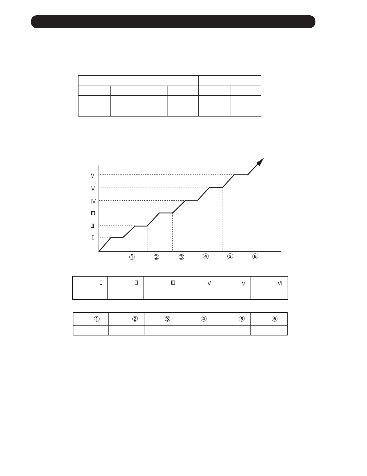
( Fig.1 : Limit of Maximum Frequency based on Outdoor Temperature )
1. COOLING OPERATION
1-1 COOLING CAPACITY CONTROL
A sensor (room temperature thermistor) built in the indoor unit body will usually perceive
difference or variation between a set temperature and present room temperature, and
controls the operation frequency of the compressor.
* If the room temperature is 6.0°C higher than a set temperature, the compressor operation
frequency will attain to maximum performance.
minimum
frequency
maximum
frequency
15rps 63rps
Outside air Outside air
temperature drops temperature rises
36°C
A zone
34°C
32°C
B zone
30°C
21°C
C zone
19°C
D zone
Hi Me Lo Quiet
( Table 1 : Compressor Frequency Range )
01-01
E zone
F zone
10°C
0°C
12°C
2°C
* When the room temperature is between +6.0°C to -1.0°C of the setting temperature,
the compressor frequency is controlled within the range shown in Table1.
However, the maximum frequency is limited in the range shown in Figure1 based on the
fan speed mode and the outdoor temperature.
* If the room temperature is 1.0°C lower than a set temperature,
the compressor will be stopped.
A zone 63rps 32rps 26rps 17rps
B zone 63rps 32rps 26rps 17rps
C zone 52rps 32rps 26rps 17rps
D zone 39rps 26rps 22rps 17rps
E zone 39rps 26rps 17rps 15rps
F zone 39rps 26rps 17rps 15rps
Page 6

2. HEATING OPERATION
2-1 HEATING CAPACITY CONTROL
A sensor (room temperature thermistor) built in the indoor unit body will usually perceive
difference or variation between a set temperature and present room temperature, and
controls the operation frequency of the compressor.
* If the room temperature is lower by 6.0°C than a set temperature, the compressor operation
frequency will attain to maximum performance.
* If the room temperature is 1.0°C higher than a set temperature,
the compressor will be stopped.
* When the room temperature is between +1.0°C to -6.0°C of the setting temperature,
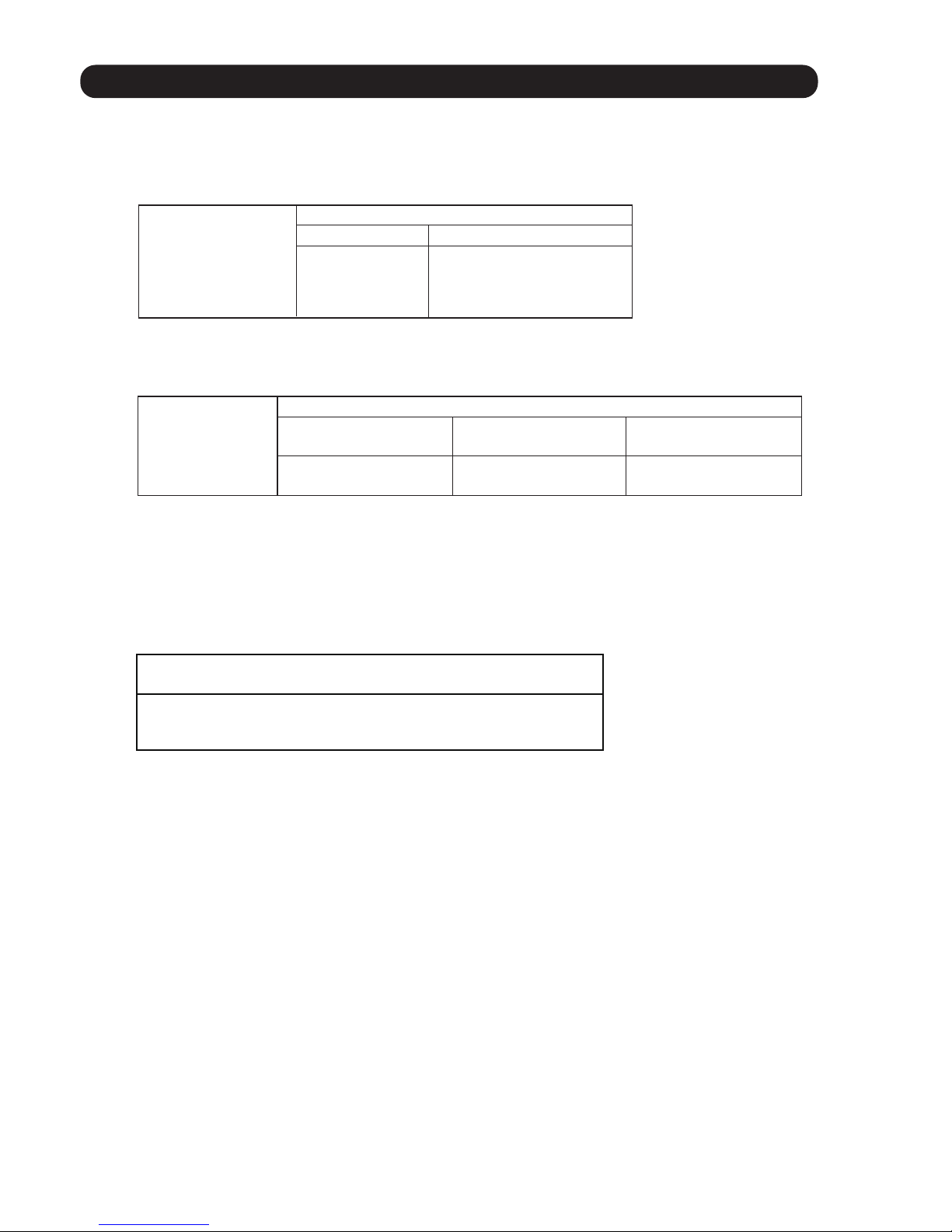
the compressor frequency is controlled within the range shown in Table2.
( Table 2 : Compressor Frequency Range )
01-02
minimum
frequency
maximum
frequency
15rps 128rps
3. DRY OPERATION
3-1 INDOOR UNIT CONTROL
The compressor rotation frequency shall change according to the temperature, set temperature,
and room temperature variation which the room temperature sensor of the indoor unit body has
detected as shown in the Table3.
Ts+0.5°C
Ts -1.5°C
Ts -0.5°C
Ts+1.5°C
( Table3 : Compressor frequency )
( Fig.2 : Compressor Control based on Room Temperature )
Operating
frequency
J zone
Y zone
X zone 22rps
15rps
0rps
Room
temperature drops
Room
temperature rises
X zone
J zone
Y zone
Page 7

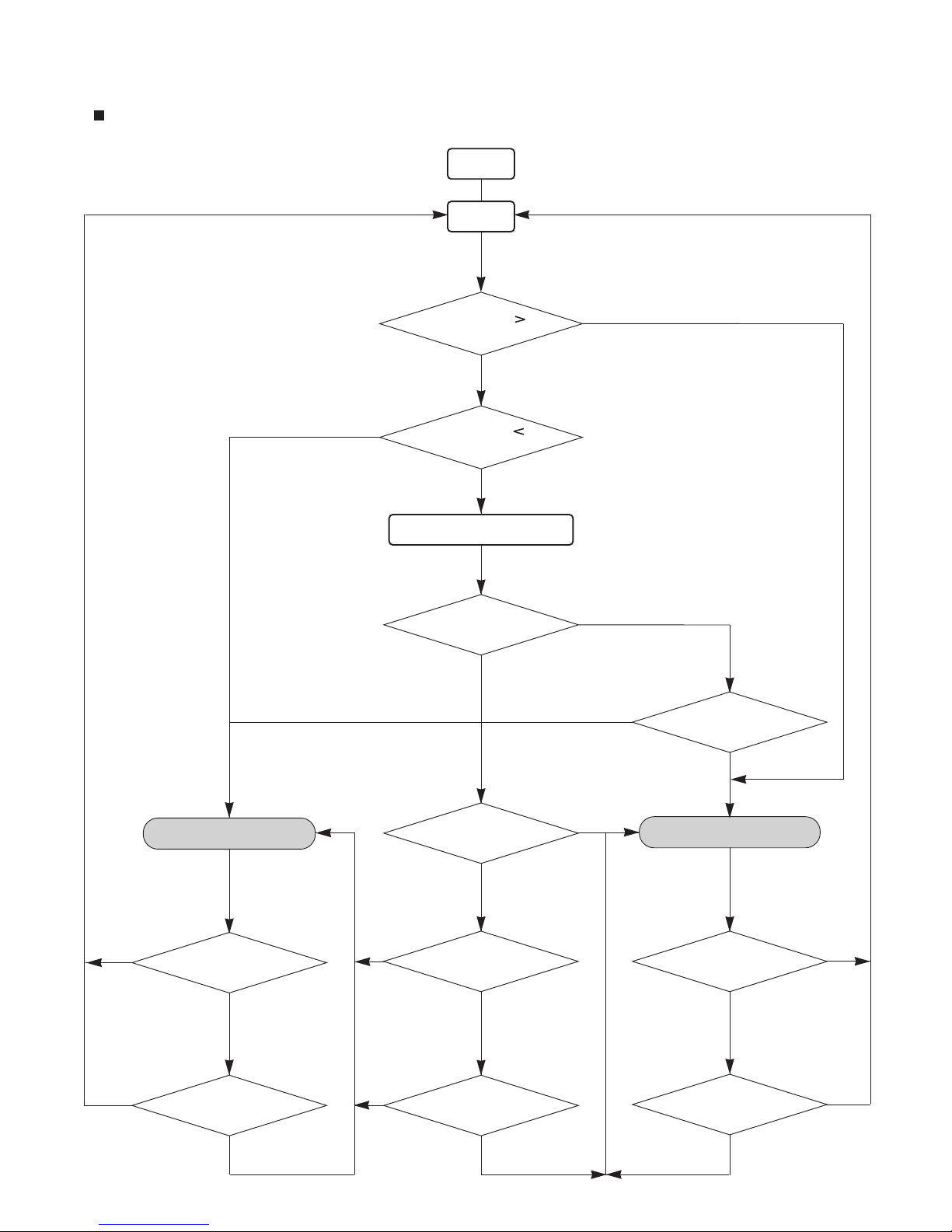
4. AUTO CHANGEOVER OPERATION
01-03
When the air conditioner is set to the Auto mode by remote controller, operation starts in the optimum
mode from among the Heating, Cooling, and Monitoring mode. During operation, the
optimum mode is automatically switched in accordance with temperature changes. The temperature
can be set between 18°C and 30°C in 1.0°C steps.
When operation starts, indoor main fan and outdoor fan are operated for around 1 minutes.
Room temperature and outdoor temperature are sensed, and the operation mode is selected
in accordance with the table below. <Monitoring mode>
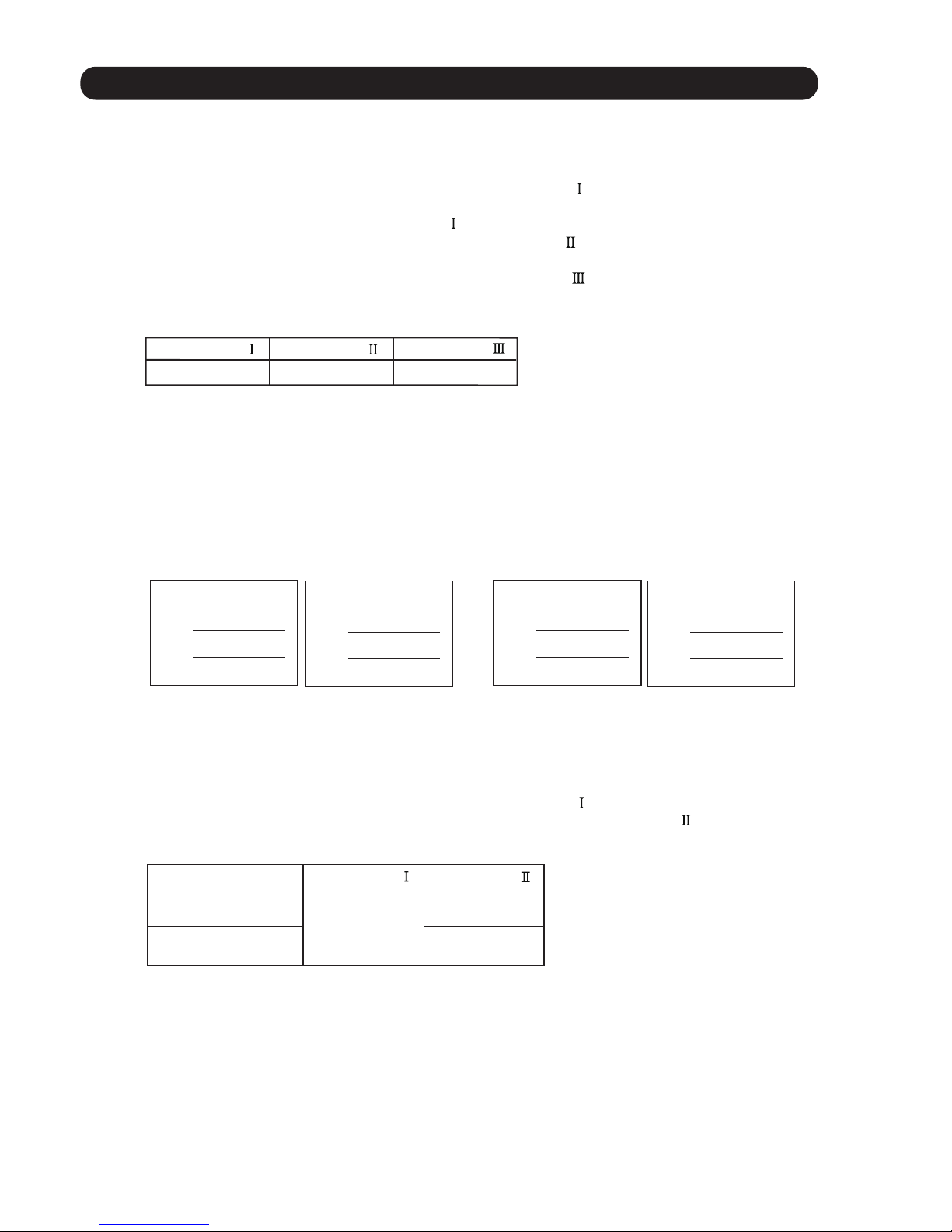
( Table 4 : Operation mode selection table )
Room temperature (TR)
TR> Ts+2°C
Ts+2°C TR Ts -2°C
*Middle zone
TR < Ts -2°C Heating
When the compressor was stopped for 6 consecutive minutes by the temperature control function
after the Cooling or Heating mode was selected at above, operation is switched
to Monitoring and the operation mode is selected again.
When the middle zone is selected on the predetermining of the operation mode, the operation mode
before the changing to the monitor mode is selected.
1
2
3
1
( Fig.3 : Outdoor temperature zone selection )
Cooling
Operation mode
Temperature
25
°C and over
25
°C under
Heating
Cooling
Mode
*If it's Middle zone, operation mode of indoor unit is selected as below.
(1). Selected by the outdoor temperature.
If outdoor unit is operating in other than Cooling and Heating mode, indoor unit will be operated
according to the outdoor temperature as below.
TR : Room temperature
Ts : Setting temperature
Page 8
01-04
START
Room temp.
Ts+2
°C?
COOLING OPERATIONHEATING OPERATION
YES
Auto change over is
second or more?
NO
NO
YES
NO
NO
AUTO CHANGEOVER operation flow chart
TS : Setting temperature
Room temp.
Ts -2
°C?
Thermostat remains
in OFF state for 6 minutes or
longer?
System stops
or operation command other than
auto changeover operation?
NO
Thermostat remains
in OFF state for 6 minutes or
longer?
System stops
or operation command other than
auto changeover operation?
Middle zone
NO
NO
Operation mode of
outdoor unit : Cooling?
YES
NO
Operation mode of outdoor unit
: Heating?
YES
NO
YES
Outdoor temperature<
25°C?
NO
YES
YES
YES
NO
YES
YES
Operation mode
before the monitor mode is
cooling mode?
Monitor mode
(Fig.4 Flow chart)
Page 9
5. INDOOR FAN CONTROL
The airflow setting by the remote controller can be switched in 5 steps such as AUTO, HIGH, MED,
LOW, QUIET while the indoor main fan only runs.
When Fan mode is set at (Auto), it operates on (Me) Fan Speed.
01-05
1. Fan speed
2. FAN OPERATION
( Table5 : Indoor Fan Speed )
Operation mode Air flow mode
Speed (rpm)
Cooling/ Fan
Hi
Me+
Me
Me
Lo
Lo -
Lo
Quiet
Quiet
Dry
S-Lo
1570
Heating
Hi
Cool air prevention
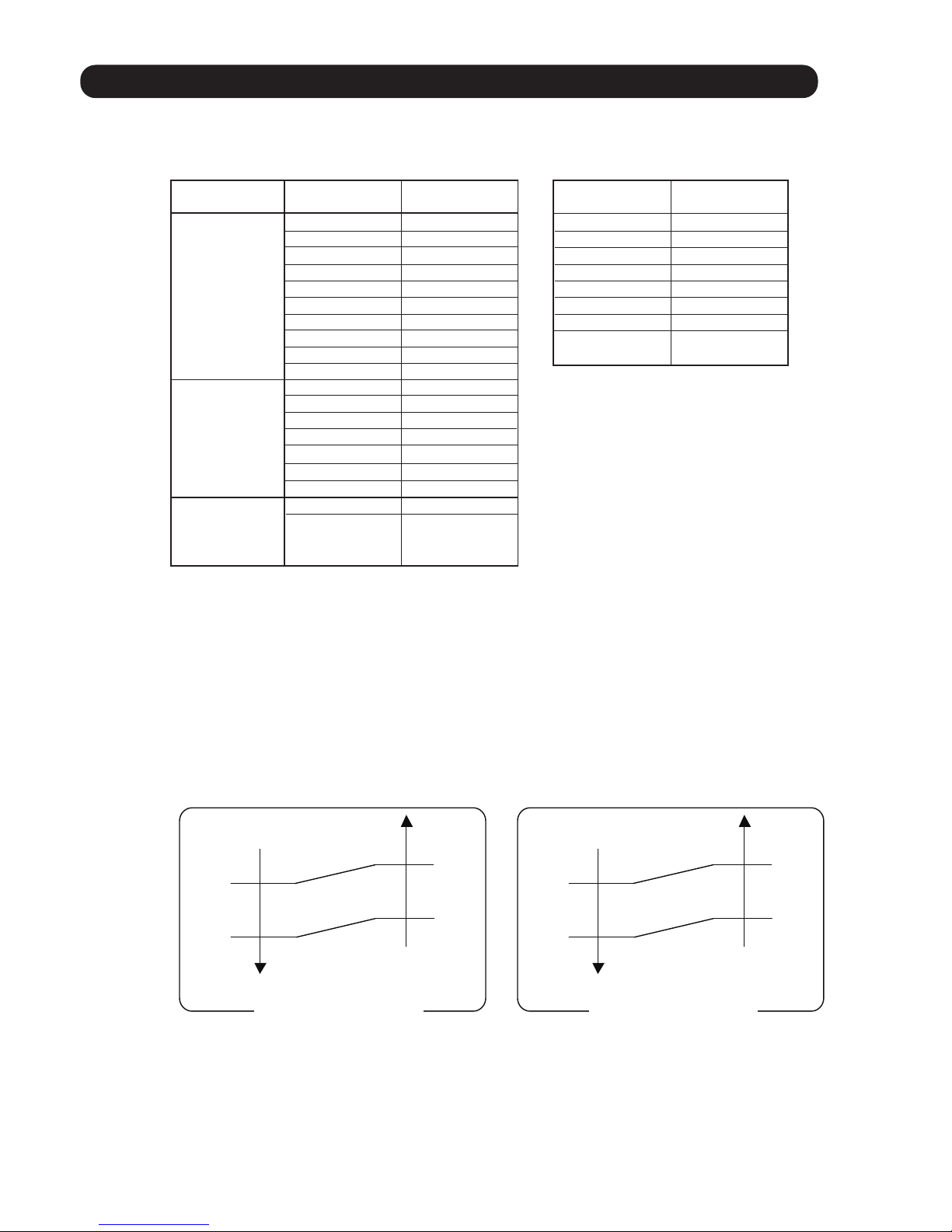
3. COOLING OPERATION
Switch the airflow [Auto], and the indoor main fan motor will run according to a room temperature,
as shown in Fig. 6.
On the other hand, if switched in [Hi] ~ [Quiet], the indoor main fan motor will run at a constant airflow of [COOL]
operation modes Quiet -, Lo -, Me, Hi, as shown in Table5.
( Fig.6 : Airflow change - over ( Cooling : Auto ) )
TR : Room temperature
Ts : Setting temperature
TR-Ts
1.5°C
0.5°C
2.5°C
1.5°C
Main Fan : Hi
Dual Fan : Lo
4. DRY OPERATION
Refer to the Table5.
During the dry mode operation, the fan speed setting can not be changed.
1490
1360
1300
1130
1130
980
830
610
1390
1310
1160
1100
960
1390
X zone : 960
J zone : 720
-
Main Fan
Air flow mode
Speed (rpm)
Hi
Me
Lo
Quiet
1290
Stop
1070
930
800
800
630
630
430
0
Dual Fan(Left Dual Fan)*
+
Lo
Cool air prevention
Quiet
+
TR-Ts
Main Fan : Lo
Dual Fan : Quiet
Main Fan : Quiet
Dual Fan : Quiet
Powerful
Powerful
Powerful
*Right Dual Fan is high +30rpm more than Left Dual Fan.
(Resonance correspondence)
Lo - 1050
Quiet - 830
780Quiet -
Powerful
TR-Ts
1.5°C
0.5°C
2.5°C
1.5°C
Main Fan : Hi
Dual Fan : Lo
TR-Ts
Main Fan : Lo
Dual Fan : Quiet
Main Fan : Lo Dual Fan : Quiet
Dual Fan setting is ON Dual Fan setting is OFF
( Fig 5 : Dual Fan Speed )
Page 10
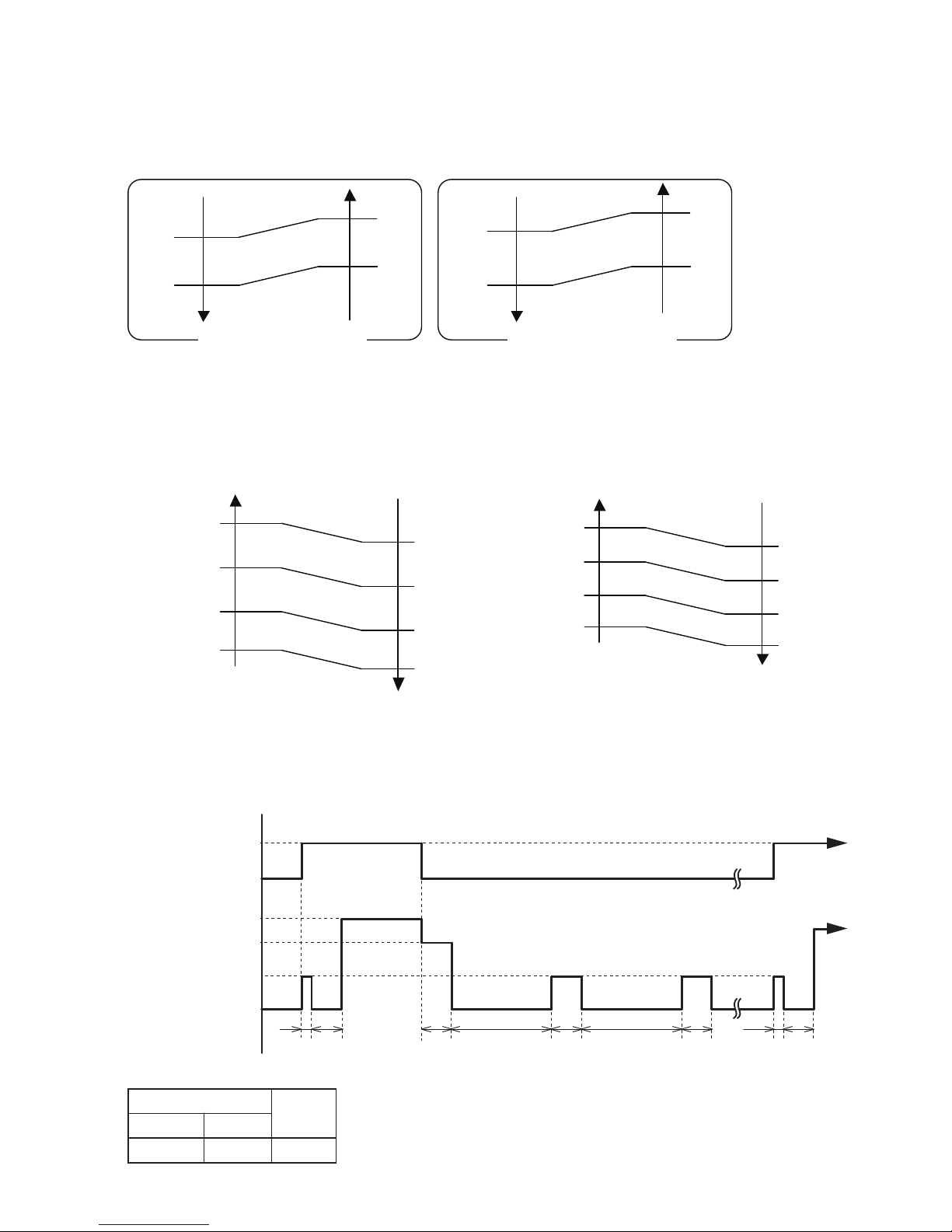
The maximum value of the indoor main fan speed is set as shown in Fig.8, based on the detected
temperature by the indoor heat exchanger sensor on heating mode.
(Fig.8 : Cool Air Prevention Control)
01-06
5. HEATING OPERATION
Switch the airflow [AUTO], and the indoor main fan motor will run according to a room temperature,
as shown in Fig. 7.
Switch the airflow at cooling mode, and the indoor main fan motor will run as shown in Fig.9.
It depends on the Function setting "Indoor unit fan control for energy saving."
On the other hand, if switched in [Hi ] ~ [Quiet ], the indoor main fan motor will run at a constant airflow
of [HEAT] operation modes Quiet -, Lo -, Me, Hi , as shown in Table5.
6. COOL AIR PREVENTION CONTROL (Heating mode)
7. INDOOR UNIT FAN CONTROL FOR ENERGY SAVING (Cooling mode)
( Fig.7 : Airflow change - over ( Heating : Auto ) )
42°C
30°C
34°C
Indoor heat exchanger
temperature
Indoor heat exchanger
temperature
*Hi or setting
Fan mode
*Me+ or setting
Fan mode
*Lo or setting
Fan mode
Cool air
prevention
39°C
37°C
37°C
32°C
28°C
S-Lo
( Fig.9 : Indoor Fan Control )
Compressor
ON
OFF
Indoor fan
Setting air flow
Indoor fan
(as shown in Table 6)
S-Lo
OFF
10 30 60 180 60 180 60 10 30
(SEC)
( Table6 : Indoor Fan Speed )
X zone J zone
960rpm 720rpm
780rpm
Dry
Cooling
[Normal operation] [Powerful operation]
Indoor heat exchanger
temperature
Indoor heat exchanger
temperature
42°C
30°C
34°C
Powerful
Hi
Lo
Cool air
prevention
39°C
37°C
37°C
32°C
28°C
S-Lo
*Lower speed is selected
TR : Room temperature
Ts : Setting temperature
TR-Ts
- 1°C
- 2°C
- 2°C
- 3°C
Main Fan : Quiet
Dual Fan : Quiet
TR-Ts
Main Fan : Me
Dual Fan : Lo
Main Fan : Hi
Dual Fan : Lo
TR-Ts
- 1°C
- 2°C
- 2°C
- 3°C
Main Fan : Lo
Dual Fan : Lo
TR-Ts
Main Fan : Me
Dual Fan : Lo
Main Fan : Hi
Dual Fan : Lo
Dual Fan setting is ON Dual Fan setting is OFF
Page 11
6. OUTDOOR FAN CONTROL
*
The outdoor fan speed mentioned above depends on the compressor frequency.
(When the compressor frequency increases, the outdoor fan speed also changes to the higher
speed. When the compressor frequency decreases, the outdoor fan speed also changes to the
lower speed.)
*
After the defrost control is operated on the heating mode, the fan speed keeps at the higher speed
as table 7 without relating to the compressor frequency.
( Table 7 : Outdoor fan speed after the defrost )
1. Fan Speed
1070rpm
01-07
( Fig.10 : Outside air temperature zone selection )
12°C
0°C
Outside air
temperature
Outside air
temperature
F zone
enoz 2-D
G zone
2°C
10°C
21°C
enoz 1-D
19°C
Cooling Heating
D-2
D-1
F
Zone
1070/ 930/ 760/ 660/ 610/ 580/ 510/ 410
Refer to Fig. 10
(rpm)
200/ 180
G 200/ 170
Dry
840/ 820/ 740/ 660/ 620/ 450
740/ 620/ 450
200/ 180
200/ 170
840/ 820/ 500/ 450/ 410
Page 12

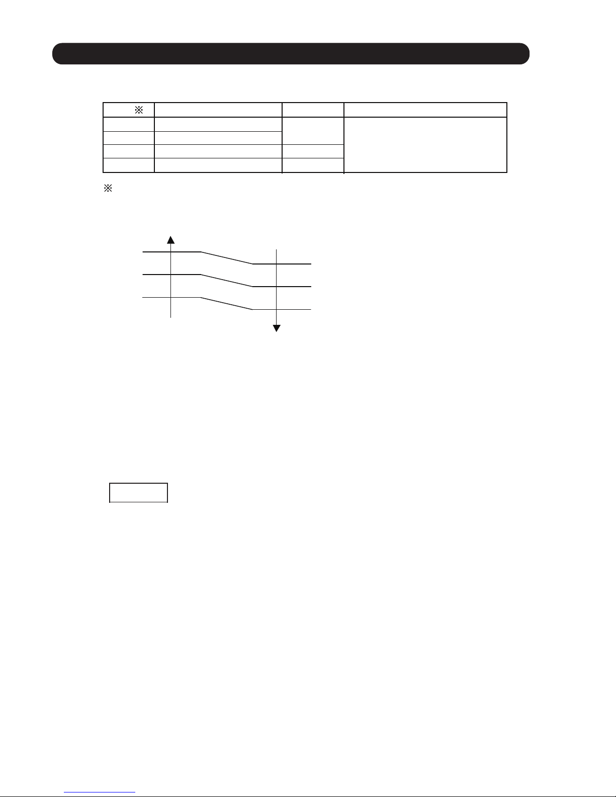
7. LOUVER CONTROL
01-08
1. VERTICAL LOUVER CONTROL
Each time the Vertical SET button is pressed, the air direction will change as follow:
At the biginning of AUTO or HEAT mode, they may stay on position 1 for a while for adjustment.
If the angle is set to position 5 - 8 for more than 30 minutes in COOL or DRY mode, the louver will autmatically
return to position 4. (*Keeping the position 5 - 8 during COOL or DRY mode may cause of condensation water drops.)
After beginning of AUTO / HEAT mode operated and automatic defrosting operation time,
the air flow will be position 1.
The airflow direction setting will temporarily become 1 when the temperature of the airflow is low at the start of
HEAT mode.
At the beginning of AUTO mode, the position you cannot change the airflow direction.
(Function Range)
3. SWING OPERATION
2. HORIZONTAL LOUVER CONTROL
(Function Range)
Each time the Vertical SET button is pressed, the air direction will change as follow:
At the beginning of AUTO mode, the position you cannot change the airflow direction.
Set the automatic swing operation, Each time the SWING Button is pressd, the operation will change.
The Left/ Right swing operation will follow the direction as shown above.
The Up/ Down Swing operation range will differ by mode as follows.
Swing operation may stop temporarily when the indoor unit fan is rotating at very low speed or is stopped.
In FAN mode, the UP/ Down swing operation range of 1 5 or 5 8 is decided according the airflow
direction previously set before starting the swing operation
(Function Range)
Up/ Down Left/ Right Up/ Down/ Left/ Right Stop swing
COOL or DRY mode HEAT mode
Horizontal air flow direction louver
COOL, DRY, or FAN mode
HEAT or FAN mode
*: Default setting
*: Default setting
Page 13

8. DUAL FAN CONTROL
In COOL mode
1. DUAL FAN COMFORT
01-09
In HEAT mode
Cold airflow
Delivers airflow with a
comfortable temperature.
Side airflow reduces warm air
from rising up, warming from
the floor level.
Warm air
The 2 types of airflow(cold/warm air from the main fan, and ambient temperature air from the dual fan)
provide comfort through the room.
This is recommended for those who do not like ordinary COOL/HEAT modes.
2. Operation
Dual FAN is OFF at the time of purchase.
To activate the dual dan comfort, press the “DUAL FAN COMFORT” button.
will be flashing on the remote controller display.
To deactivate the dual fan comfort, press the “DUAL FAN COMFORT” button. again.
will no longer be shown on the remote controller display.
Dual fan operates with the recommended setting. (Refer to the Fig. 11)
Dual fan does not operates in TEST operation by indoor unit button.
Operation only with dual fan is not possible.
In HEAT mode, there is no dual fan airflow with the following.
- When the room temperature is lower than the set temperature
- When the temperature of HEAT airflow is low
- During autmatic defrosting operation
In AUTO mode, there is no dual fan airflow with the following.
- When the room temperatrure is under the monitoring in AUTO mode.
(Fig. 11 )
3. Setting
The position of dual fan in COOL, DRY or FAN mode can change so that the airflows further.
( For the case that the opposite wall is far from the indoor unit, and the air agitation is required.)
1. Turn off the indoor unit by pressing the “Start/Stop ” button.
2. Press the “DUAL FAN COMFORT” button for at least 5 seconds until the current “DUAL FAN”
status is displayed.
3. Press the “TEMP.” buttons to switch the setting.
“1” (Standard) “2” (Far) *
4. Press the “Start/ Stop ”button to send the setting to the indoor unit. After the status is sent,
the display will automatically return to the original screen.
*If no buttons are pressed within 30 seconds after the “DUAL FAN” status is displayed, the system
returns to the original clock display. In this case, start again from setp 1.
If this still does not match the preferences. see the function setting.
Louver position
1 (Horizontal)
2
3
4
5
6
7
8 (Blow down)
Dual fan positoin
COOL
DRY HEAT
FAN *
7 1
7 1
7 2
7
2
7 3
7 4
7 5
7 6
The dual fan position is controlled together with the louver position Up / Down.
The fan speed is controlled with the fan speed of main fan and the louver position Right / Left.
*The position 7: (Standard) is able to change to the postion 5: (Far) upward. Refer to the setting.
Remarks
Default setting COOL/ DRY/ FAN
The lowest down position in dew water protection (COOL/ DRY)
Default setting HEAT
Page 14
9. COMPRESSOR CONTROL
1. OPERATION FREQUENCY RANGE
The operation frequency of the compressor is different based on the operation mode as
shown in Table 8.
Cooling
Min
Max
)egnaR ycneuqerF noitarepO rosserpmoC : 8 elbaT(
01-10
15rps 63rps
2. OPERATION FREQUENCY CONTROL AT START UP
The compressor frequency soon after the start-up is controlled as shown in Fig.12.
(Fig.12 : Compressor Control at Start-up)
Time
Time Time
Frequency
Frequency
Frequency
Time
Time Time
80sec 110sec 140sec
(Time)
29rps 53rps 65rps
(Frequency)
Frequency
Frequency
Frequency
Min
Max
15rps 128rps
Dry
Min
Max
15rps 22rps
Heating
Frequency
Frequency
Frequency
Time
Time Time
72rps 91rps 99rps
Frequency
Frequency
Frequency
Time
Time Time
200sec 350sec 410sec
Page 15

10. TIMER OPERATION CONTROL
1. ON TIMER / OFF TIMER
The Table 9 shows the available timer setting based on the product model.
ON TIMER / OFF TIMER PROGRAM TIMER SLEEP TIMER
OFF timer : When the clock reaches the set time, the air conditioner will be turned off.
Operation mode
Stop mode
Set time of timer
ON timer : When the clock reaches the set time, the air conditioner will be turned on.
Operation mode
Stop mode
Set time of timer
The program timer allows the OFF timer and ON timer to be used in combination one time.
Operation mode
Operation will start from the timer setting (either OFF timer or ON timer) whichever is closest
to the clock's current timer setting.
The order of operations is indicated by the arrow in the remote control unit's display.
SLEEP timer operation cannot be combined with ON timer operation.
( Table 9 : Timer setting )
2. PROGRAM TIMER
Stop mode
Stop mode
Stop mode
Operation mode
Operation mode
Set time Set time Set time Set time
10-1 WIRELESS REMOTE CONTROLLER
01-11
Page 16

3. SLEEP TIMER
If the sleep is set, the room temperature is monitored and the operation is stopped automatically.
If the operation mode or the set temperature is change after the sleep timer is set, the operation is
continued according to the changed setting of the sleep timer from that time ON.
Set temperature rises
( Ts : Set temperature )
Stop of operation
Set temperature lowers
( Ts : Set temperature )
Ts
Stop of operation
In the cooling operation mode
When the sleep timer is set, the setting temperature is increased 1°C
It increases the setting temperature another 1°C after 1 hour.
After that, the setting temperature is not changed and the operation is stopped at the time
of timer setting.
Ts
+1°C
+2°C
Set
60min
In the heating operation mode
When the sleep timer is set, the setting temperature is decreased 1°C
It decreases the setting temperature another 1°C every 30 minutes.
Upon lowering 4°C, the setting temperature is not changed and the operation stops at
the time of timer setting.
Set
30min
30min
30min
-4°C
-3°C
-2°C
-1°C
01-12
Page 17

11. ELECTRONIC EXPANSION VALVE CONTROL
The most proper opening of the electronic expansion valve is calculated and controlled under the
present operating condition based on the Table10.
The compressor frequency, the temperatures detected by the discharge temperature sensor, the
indoor heat exchanger sensor, the outdoor heat exchanger sensor,
and the outdoor temperature sensor.
At the time of supplying the power to the outdoor unit, the initialization of the electronic
expansion valve is operated (528 pulses are input to the closing direction).
12. TEST OPERATION CONTROL
The compressor won't enter operation status for 140 sec. after the compressor is stopped,
even if any operation is given.
13. PREVENT TO RESTART ( ST )
01-13
( Table10 : The pulse range of the electronic expansion valve control )
Cooling / Dry mode
Heating mode
Operation mode Pulse range
between 32 to 480 pulses.
between 32 to 480 pulses.
Operation method
Before starting the test run, wait for 1 minute after connecting the power supply.
By the wireless remote controller
• To start the test run, press the “Start/Stop ” “ button, the “TEST RUN” button on the remote controller with a
by using the tip of a ballpoint pen or other small object.
By the indoor unit button
• To start the test run, keep on pressing the “INDOOR UNIT” button of the indoor unit for more than 10 sec.
• To end test operation, press the remote controller “Start/Stop ” button.
(When the air conditioner is running by pressing the “TEST RUN” button, the “OPERATION” indicator and
“TIMER” indicator blink simultaneously.)
Page 18

16. FORCED AUTO OPERATION
If the Indoor unit button is pressed 3 to 10 sec. the operation is controlled as
shown in Table 11. (If the remote controller is lost, this function can use.)
The Operation indicator and the Timer indicator blinks for 1 sec, ON, and 1 sec. OFF.
The forced auto operation is released after 60 min. after starting the operation.
By pressing the Indoor unit button for 3sec., the operation stops.
OPERATION MODE Auto changeover
FAN CONT. MODE Auto
TIMER MODE Continuous (No timer setting available)
SETTING TEMP. 24°C
SETTING LOUVER Standard / Momorized position
(Table11)
01-14
17. FORCED COOLING OPERATION
Manual auto operation
If the Indoor unit button is pressed over 10 sec., the operation is controlled as
shown in Table 12. (If the remote controller is lost, this function can use.)
The Operation indicator and the Timer indicator blinks for 1 sec, ON, and 1 sec. OFF.
The forced auto operation is released after 60 min. after starting the operation.
By pressing Indoor unit button for 3 sec., the operation stops.
When the power was interrupted by a power failure, etc. during operation, the operation contents
at that time are memorized and when power is recovered, operation is automatically started with
the memorized operation contents.
When the power is interrupted and recovered during timer operation, since the timer operation time
is shifted by the time the power was interrupted, an alarm is given by blinking slowly (6 sec ON/2 sec OFF)
the indoor unit body timer indicator.
[ Operation contents memorized when the power is interrupted ]
Operation mode
Set temperature
Set air flow
Timer mode and timer time
Set air flow Direction
S
Human sensor setting
Low noise operation
wing
ECONOMY operation
10°C HEAT operation
15. AUTO RESTART
At the time when the air conditioner is switched from the cooling mode to heating mode, the
compressor is stopped, and the four-way valve is switched in 140 sec. later aftter the compressor
Stopped.
14. FOUR-WAY VALVE EXTENSION SELECT
DUAL FAN
HUMAN SENSOR
ECONOMY
SWING
OFF
OFF
OFF
OFF
OPERATION MODE COOL
FAN CONT. MODE Hi
TIMER MODE Continuous (No timer setting available)
SETTING TEMP. 24°C
SETTING LOUVER Standard
Manual auto operation
DUAL FAN
HUMAN SENSOR
ECONOMY
SWING
OFF
OFF
OFF
OFF
(Table12)
At the time when the compressor stopped during heating mode, the four-way valve position changes to the
cooling position with certain period as follows.
- When the compressor is stopped by the operation STOP: after 140 sec.
- When the compressor is stopped by other than above: after 1800 sec.
Page 19

01-15
When the time erapsed 30 min, after compressor stopped, and whren the outdoor heat exchanger
temperature sensor detects lower temperature, the preheating starts.
When the operation starts, the preheating stops.
The preheating does not oeprate when the system is stopped with Error of permanent stop.
18. COMPRESSOR PREHEATING
) gnitaeherP rosserpmoC : 31.giF (
7°C
5°C
19. 10°C HEAT OPERATION
The 10°C HEAT operation functions by pressing 10°C HEAT button on the remote controller.
The 10°C HEAT operation is almost the same operation as below settings.
Mode Heating
Setting temperature 10°C
Fan mode Lo (AUTO)
( Table13 )
20. ECONOMY OPERATION
The ECONOMY operation functions by pressing ECONOMY button on the remote controller.
The ECONOMY operation is almost the same operation as below settings.
Mode Cooling/ Dry Heating
Target temperature Setting temp.+1°C Setting temp.-1°C
( Table14)
0°C
C°2-
-2°C
C°4-
OFF
OFF
ON
ON
14°C
C°21
0°C
C°2-
-2°C
C°4-
OFF
ON
ON
ON
JUMPER (J600) removed
When the 10°C HEAT operation is operating, the ECONMY indicator turns ON.
Page 20
21. DEFROST OPERATION CONTROL
01-16
1. CONDITION OF STARTING THE DEFROST OPERATION
The defrost operation starts when the outdoor heat exchanger temperature sensor (Tn) detects
the temperature lower than the values shown in Table15.
2. CONDITION OF THE DEFROST OPERATION COMPLETION
Defrost operation is released when the conditions become as shown in Table16.
( Table16 : Defrost Release Condition )
Release Condition
Outdoor heat exchanger temperature sensor value is higher than
+16°C
or Compressor operation time has passed 15min.
( Table 15 : Condition of starting Defrost Operation )
Defrosting (Normal)
starting operation
Compressor integrating operation time
Compressor integrating operation time
Less than 40min. More than 40min.
Does not operate
Integrating defrost
(Constant monitoring)
More than 240min.
(For long continuous operation)
Less than 10min.*1
(For intermittent operation)
- 3°C
More than 215min.
(For long continuous operation)
- 5°C
OFF count of the compressor
40 times.
*1 : If the compressor continuous operation time is less than 10 min, the OFF number of the compressor is counted.
If any defrost operated, the compressor OFF count is cleared.
Tn-Tn10 < - 5deg
Tn-Tnb < - 2deg
However, Tn < - 6°C
=
Tn10 : Temperature of continuous operation at 10minutes.
Tnb : Back 5minutes temperature
Tn < - 17°C
=
Page 21

01-17
Compressor OFF
Outdoor fan motor OFF
50sec. later four - way valve OFF
55sec. later compressor ON
3. Defrost Flow Chart
The defrosting shall proceed by the integrating operation time, outdoor temperature
and outdoor heat exchanger temperature as follows.
(Not defrosted for 10min.)
Heating operation start : Compressor ON
Outdoor heat exchanger temperature:
Over +16°C
or
Compressor ON time: Maximum 15min.
Defrost end
Integrating defrost
(Constant monitoring)
Defrost Indicator:
[Operation indicator]
6sec. ON / 2sec. OFF
Defrost start
Compressor
OFF count :
40 times
(Less than 10min.)
Normal defrost
Compressor
integrating
operation:
Over 240min.
Outdoor
heat exchanger
temperature:
Below - 3°C
Compressor
integrating
operation:
Over 215min.
Outdoor
heat exchanger
temperature:
Below - 5°C
Compressor
integrating
operation:
Over 40min.
Tn-Tn10 < - 5deg
Tn-Tnb < - 2deg
However, Tn < - 6 °C
=
Tn < - 17°C
=
Page 22

22. OFF DEFROST OPEARTION CONTROL
1. OFF DEFROST OPERATION CONDITION
When operation stops in the [Heating] mode, if frost is adhered to the outdoor unit heat
exchanger, the defrost operation will proceed automatically. In this time, if indoor unit operation
indicator flashes slowly (6 sec ON / 2 sec OFF), the outdoor unit will allow the heat exchanger to defrost,
and then stop.
In heating operation, the outdoor heat exchanger temperature is less than -4°C,
compressor continuous operation more than 10 minutes, and
compressor operation integrating time lasts for more than 30 minutes.
OFF Defrost Flow Chart
Heating operation stop
Outdoor heat exchanger temperature :
Below -4°C
Compressor continuous operation :
Over 10 minutes
Compressor integrating operation :
Over 30 minutes
Defrost start
Defrost Indicater:
[Operation indicator]
6 sec ON / 2 sec OFF
Outdoor heat exchanger temperature :
Over +16°C
or
Compressor ON time : Maximum 15 minutes
Defrost end
2. OFF DEFROST END CONDITION
Release Condition
Outdoor heat exchanger temperature sensor value is higher than +16°C
or Compressor operation time has passed 15 minutes.
01-18
Page 23
23. VARIOUS PROTECTIONS
1. DISCHARGE GAS TEMPERATURE OVERRISE PREVENSION CONTROL
The discharge gas thermosensor (discharge thermistor : Outdoor side) will detect discharge gas
temperature.
When the discharge temperature becomes higher than Temperature , the compressor frequency
is decreased 20rps, and it continues to decrease the frequency for 20rps every 120 seconds until
the temperature becoms lower than Temperature .
When the discharge temperature becomes lower than Temperature , the control of the control of
the compressor frequency is released.
When the discharge temperature becomes higher than Temperature , the compressor is stopped
and the indoor unit indicator starts blinking.
104°C 101°C 110°C
( Table 17 : Discharge Temperature Over Rise Prevension Control / Release Temperature )
Temperature
Temperature
Temperature
2. CURRENT RELEASE CONTROL
The compressor frequency is controlled so that the outdoor unit input current does not exceeds
the current limit velue that was set up with the outdoor temperature.
The compressor frequency returns to the designated frequency of the indoor unit at the time
when the frequency becomes lower than the release value.
( Table 18 : Current Release Operation Value / Release Value)
01-19
[ Heating ]
[ Cooling ]
TO (Control / Release)
4.5A / 4.0A
6.0A / 5.5A
7.0A / 6.5A
46°C
40°C
TO (Control / Release)
8.5A / 8.0A
10.5A / 10.0A
12.5A / 12.0A
17°C
12°C
[ Heating ]
TO : Outdoor Temperature
[ Cooling ]
TO (Control / Release)
5.0A / 4.5A
6.5A / 6.0A
7.5A / 7.0A
46°C
40°C
TO (Control / Release)
10.5A / 10.0A
12.5A / 12.0A
14.5A / 14.0A
17°C
12°C
Model 09
Model 12
3. ANTIFREEZING CONTROL (Cooling and Dry mode)
The compressor frequency is decrease on cooling & dry mode when the indoor heat exchanger
temperature sensor detects the temperature lower than Temperature .
Then, the anti-freezing control is released when it becomes higher than Temperature .
( Table 19 : Anti-freezing Protection Operation / Release Temperature )
Outdoor temperature
Over than 10°C *1
or 12°C *2
Less than 10°C *1
or 12°C *2
*1. When the temperature rises.
*2. When the temperature drops.
4°C
7°C
13°C
Temperature
Temperature
Page 24

01-20
4. COOLING PRESSURE OVERRISE PROTECTION
When the outdoor unit heat exchange sensor temperature rises to 65°C or greater the compressor is
stopped.The compressor restarst after the 140 sec, erapsed (ST). and the temperature detection starts
60 sec. erapsed after compressor started.
5. HIGH TEMPERATURE AND HIGH PRESSURE RELEASE CONTROL ( HEATING MODE )
On heating mode, the compressor frequency is controlled as following based on the detection value of the indoor
heat exchanger temperature sensor.
Indoor heat exchange
temperature rises
Indoor heat exchange
temperature drops
[ Control System ]
It returns to the normal operation
Compressor is stopped
53°C
55°C
63°C
50°C
The compressor frequency is
decreased 4rps every
120seconds.
The compressor frequency is
decreased 25rps every
120seconds.
6. HIGH PRESSURE PROTECTION
When the pressure switch becomes OFF (Open : higher than 4.2 MPa),
the compressor is stopped.
It is released when the pressure switch becomes ON (Close : lower than 3.2 MPa)
after 140sec. of compressor stop.
Stable zone
7. 4 way valve protection
The 4 way valve protection operates with the following conditions.
1. When the compresspr operates for more than 20 minutes.
2. Tn (Indoor unit HEX temp) -Tb (Room temp) > 10 deg in COOL and DRY
3. Tn (Indoor unit HEX temp) -Tb (Room temp) < -10 deg in HEAT
When the above condition 1&2 or 1&3 repeat 2 times for 2 min, the compressor stops.
When the same condition repeats 5 times, the system indicates the Error code.
8. Dew water protection (Operating in COOL, DRY)
When the vertical louver is set the position 5 ~ 8, and when the operating time erapsed 30 minutes,
the louver position changes automatically to the position 4.
9. EEV shutoff protection (Operating in HEAT)
The EEV shutoff protection operates with the following conditions.
1. When the compresspr operates for more than 20 minutes.
2. Tn (Indoor unit HEX temp) -Tb (Room temp) < 4 deg
When the above condition 1 and 2 repeat 2 times in 2 min, the compressor stops.
After the ST (Restart protection), the compressor starts.
Page 25
01-21
24. LOW NOISE OPERATION
Operating mode
COOL, DRY
HEAT
Outdoor fan speed
[rpm]
Compressor speed
[rps]
The compressor speed and the outdoor unit fan speed are limited to reduce the operation noise
by presssing “LOW NOISE” button on the remote controller.
However, during the DEFROST OPERATION, the compressor operates by the speed
for DEFROST OPERATION.
660
660
32
32
*The performance drops when operating in the LOW NOISE OPERATION.
25. HUMAN SENSOR (Energy Saving)
•
• Details about detection with the human sensor
• The human sensor detects whether there are people in the room
by looking for movement by people in the room.
About the ENERGY SAVING Operation
If no one enters the room for approximately 20 minutes, the set temperature
will be automatically controlled.
(When someone comes back into the room, the human sensor will detect this,
and automatically revert to the original settings.)
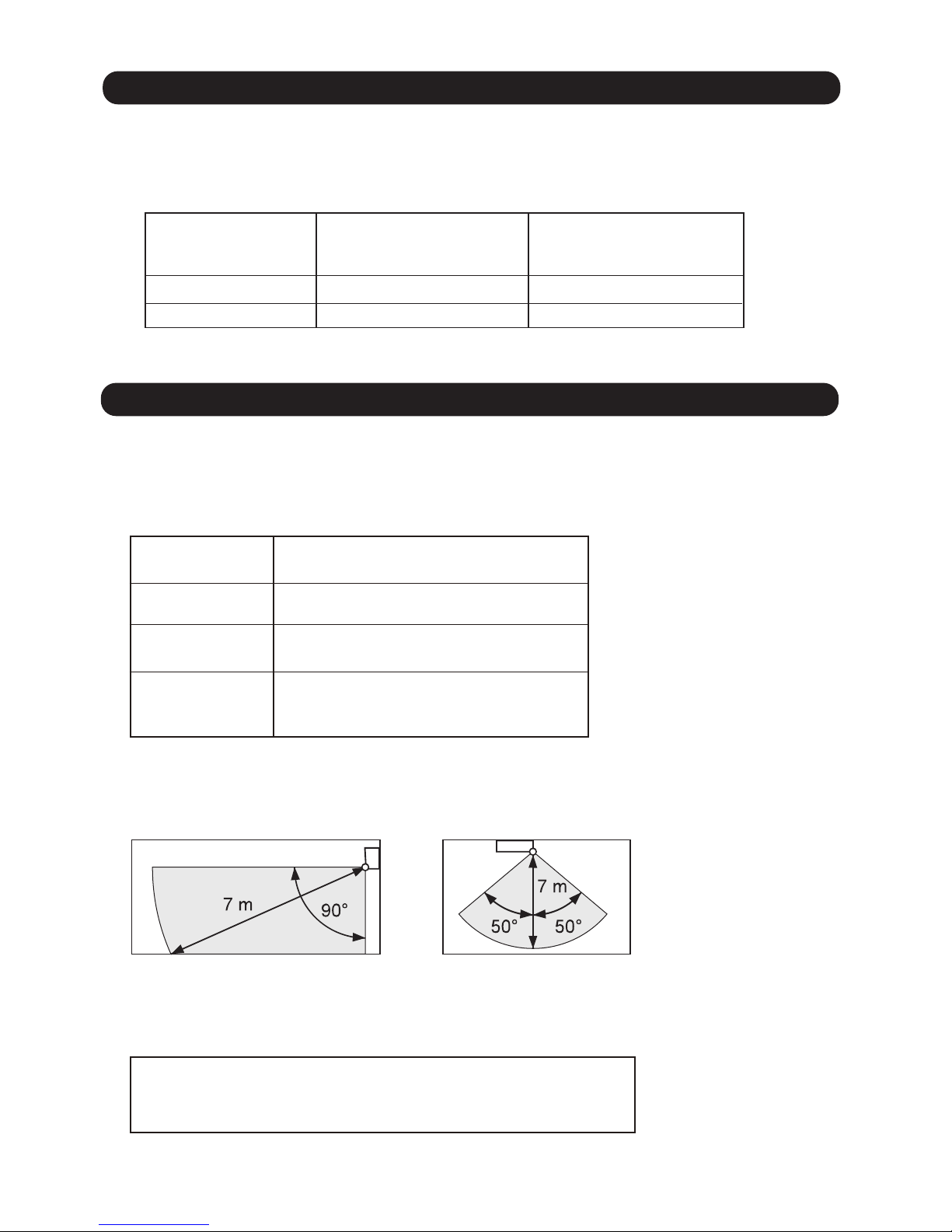
Operation mode
About the HUMAN SENSOR
Cool / Dry
Heat
Auto
Operation details
(if there is no one in the room for a while)
The set temperature will be increased by
a maximum of approximately 2
°C.
Application range is follows.
Vertical angle 90
°(Side view)
ENERGY SAVING function may not work when the room temperature is very
different from the temperature defined in temperature setting,
such as when immediately after starting the operation
Horizontal angle 100
°(Top view)
The set temperature will be decreased by
a maximum of approximately 4
°C.
This runs the ENERGY SAVING function
automatically for the selected mode
(Cooling/ Heating/ Drying)
* High limit : 30°C
* Low limit : 16°C
* When using together with the SLEEP time, the SLEEP timer will be prioritized.
* During 10°C HEAT operation, if there is no one in the room the set temperature will not be changed.
Page 26

01-22
26. POWERFUL OPERATION
The Powerful operation functions by pressing POWERFUL button on the remote controller.
The indoor unit & outdoor unit will operate at maximum power as shown in Table 20.
Release Condition is as follows.
[Cooling / Dry]
- Room tenperature < Setting temperature - 0.5°C or Operation time has passed 20 min..
COMPRESSOR FREQUENCY Maximum
FAN CONT. MODE Powerful
SETTING LOUVER Cooling/ Dry : 4, Heating : 7
(Table 20)
Powerful operation
=
=
[Heating]
- Room tenperature > Setting temperature +0.5°C or Operation time has passed 20 min..
27. FILTER CLEAN
The Filter clean function operates with the following conditions.
1. Auto filter clean
When the air conditioner operating time reached 40 hours*.
*Filter clean operation interval time can change by the function setting.
2. Manual filter clean
When the Filter Clean button on the remote controller is pressed.
The filter cleaning time is approximately 13 min..
The indoor unit “FILTER CLEAN” indicator lights up during filter cleaning.
When the FILTER CLEAN indicator blinks slowly, this indicates that it is time to clean the dust
box. (After approximately 10,000 hours of air conditioner operation have elapsed.)
After cleaning the dust box, press Indoor unit button less than 3 sec..
By pressing the indoor unit button, the accumulated operation time is reset.
When the indicator brinks as follows, check filter installing (refer to the operation manual.)
28. PLASMA CLEAN
The plasma clean function operates with the following conditions.
- When the plasma air clean button on the remote controller is pressed.
- When the Indoor unit main fan is rotating at very low speed or is stopped.
The indoor unit “PLASMA AIR CLEAN” indicator lights up during the functioning.
When the PLASMA AIR CLEAN indicator blinks slowly, this indicates that it is time to clean the
plasma air clean unit. (After approximately 1,100 hours of plasma air clean operation have
elapsed.) After cleaning the plazma clean unit (refer to the operation manual), press Indoor unit
button less than 3 sec..
By pressing the indoor unit button, the accumulated operation time is reset.
When the PLASMA AIR CLEAN indicator blinks, this indicates that the plasma clean unit is wet,
dirty or the intake grille is opened.
In this case, stop the air conditioner and then check intake grille or clean the plasma clean unit
and dry it completely.
Page 27

01-23
29. WIRELESS LAN
The operation with the wireless LAN is possible by using the wireless LAN adaptor (packaged with
the manuals), and by performing the network setting.
1) Wireless LAN adaptor
2) Wireless LAN router
3) Internet
4) Mobile device
and Mobile app
CLOUD
1) Wireless LAN adaptor
The adaptor is packaged with the manuals.
The SSID is in the label with the wireless LAN adaptor.
For the installing and setting, refer to the installation manual and the setting manual.
The wireless adaptor has the LED indicator, and it indicates the status.
In case of trouble, refer to the troubleshooting or setting manual.
2) Wireless LAN router
Loacl purchase (use the user’s product)
PIN code or WPS (serting) is required for linking with the wireless LAN adaptor.
The internet connection is required.
3) Internet
The operation and the status indication are performed via the Internet.
4) Moble device and Mobile app
Mobile app (application software) “ FGLair” has to be installed to the user’s mobile device.
(For installing the app, the user registeration is required. Refer to the setting manual.)
The function available on the mobile device may differ from the finction on the remote controller.
(Refer to the operation manual of mobile app)
Page 28

2 . TROUBLESHOOTING
WALL MOUNTED type
INVERTER
Page 29

2-1 INDOOR UNIT ERROR DISPLAY
Please refer the flashing pattern as follows.
The OPERATION, TIMER and ECONOMY indicators operate as follows according to the error contents.
Room Temperature Thermistor Error
Error Contents
Trouble
shooting
(Orange) (Green)
Serial Communication Error
Indoor unit Heat Ex. Thermistor Error
OPERATION, TIMER indicator : 0.5s ON / 0.5s OFF (Flash)
ECONOMY indicator: 0.1s ON / 0.1s OFF (Flash continuous)
Outdoor unit Discharge Thermistor Error
Outdoor unit Heat Ex. Thermistor Error
Outdoor Temperature Thermistor Error
Indoor Fan Motor Error
Compressor start up Error
Outdoor Unit Fan Motor Error
Side Fan ( Left ) Motor Error
Side Fan ( Right ) Motor Error
Over current Error
CT Error
Manual Auto Switch Error
Indoor Unit Display
4 Way Valve Error
Discharge Temperature Error
Power Supply Frequecy Detection Error
02-01
OPERATION TIMER ECONOMY
Indoor unit Model Information Error
Plasma air clean unit Vdd Error
Filter set abnormal
Combination Error
Outdoor unit Model Information Error
Trip terminal L Error
High pressure SW Error
1 time
1 time
2 time
3 times
3 times
3 times
4 times
4 times
5 times
5 times
5 times
5 times
5 times
6 times
6 times
7 times
7 times
7 times
8 times
8 times
9 times
9 times
9 times
9 times
10 times
1 time
8 times
3 times
1 time
2 times
5 times
1 time
2 times
1 time
4 times
5 times
9 times
10 times
2 times
5 times
1 time
3 times
4 times
4 times
6 times
4 times
5 times
7 times
9 times
1 time
1, 2
26,29,30
3
4
5
6
7
8
9
10
11
12
13
14
15
16
17
18
19
20
21
22
23
24
25
External Communication Error
INDOOR UNIT LED INDICATOR
(Green)
Continuous
Continuous
Continuous
Continuous
Continuous
Continuous
Continuous
Continuous
Continuous
Continuous
Continuous
Continuous
Continuous
Continuous
Continuous
Continuous
Continuous
Continuous
Continuous
Continuous
Continuous
Continuous
Continuous
Continuous
Continuous
Page 30

Flashing Fast : Repeating 0.5 seconds ON / 0.5 seconds OFF
Wireless LAN addapter Error
Communication Error
(”Troubleshooting 26” and “Troubleshooting 28” are
simultaneous Error)
Trouble
shooting
26
27
28
Error Contents
Wireless LAN adapter Indicator
LED 1 LED2
Network Communication Error
(Communication Error of between Wireless LAN router to
Wireless LAN adapter)
External Communication Error
(Communucation Error of between Indoor unit to wireless
LAN adapter)
ON
LED 1 (Green)
LED 2 (Orange)
WIRELESS LAN ADAPTER INDICATOR
Please refer the flashing pattern as follows.
LED 1 (green) and LED 2 (orange) operate as follow according to
the error contents.
Flashing Fast
ON
29
Wireless LAN adapter Non-Energized
OFF OFF
30
02-02
2-2 WIRELESS LAN ADAPTER ERROR DISPLAY
*The status LED1(Green) ON: The communication between the Indoor unit and the adaptor is normal.
(Green) (Orange)
Flashing Fast
Flashing Fast
Flashing Fast
Flashing Fast
Flashing Fast
Error code
18
No Error
No Error
18
18
Wireless LAN adapter Sleep mode
OFF OFF
31
No Error
Page 31

Error Name
MOBILE APP ERROR DISPLAY
If there is an abnormality on the air conditioning, you will see is as follows.
When you tap the "Error button” on the home screen, Error Code and Error Name is displayed.
For Android
For iOS
Error button
Error code
51. 1
51. 1
Error Name
Error code
Error button
2. ERROR CODE
AIR CINDITIONER ERROR
AIR CINDITIONER ERROR
51. 1
AIR CINDITIONER ERROR
51. 1
AIR CINDITIONER ERROR
Indoor unit fan motor 1 error
Indoor unit fan motor 1 error
Indoor unit fan motor 1 error
Indoor unit fan motor 1 error
02-03
23
2-3 MOBILE APP ERROR DISPLAY
Indoor unit room temp. thermistor error
Error Contents
Trouble
shooting
Serial Communication error between Indoor unit/outdoor unit
Indoor unit heat ex. temp. thermistor error
Outdoor unit discharge temp. thermistor error
Outdoor unit heat ex. temp. thermistor error
Outside air temp. thermistor error
Indoor unit fan motor 1 error
Outdoor unit compressor motor control error
Outdoor unit Fan Motor 1 error
Indoor unit fan motor 2 error
Indoor unit fan motor 3 error
Outdoor unit trip detection
Outdoor unit current sensor error
Indoor unit manual auto switch error
Outdoor unit 4 way valve error
Outdoor unit discharge temp. 1 error
Indoor unit power supply abnormal
Indoor unit main PCB error
Air cleaning function error
Indoor unit intake grille position error
Incompatible series connection error
Outdoor unit main PCB error
Outdoor unit IPM error
Outdoor unirt pressure sensor Error
11.1, 11.2, 11.3, 11.4
18.1
23.1
31.3
32.1
35.1
41.1
42.1
51.1, 51.2
54.1, 54.2
58.1
59.1
5A.1
62.1, 62.2
65.3
71.1
73.3
74.1
84.1
86.4
94.1
95.1
97.3
99.1
A1.1
1, 2
26,29,30
3
4
5
6
7
8
9
10
11
12
13
14
15
16
17
18
19
20
21
22
23
24
25
External Communication error
Applicable Error code
Page 32

Error
messages
1. ERROR DISPLAY
If there is an abnormality on the Wireless LAN control system, you will see is as follows.
Error messages will disappear at 5 seconds. Then retune to normal display.
For Android
For iOS
2. ERROR MESSAGES LIST
Erro
r
messages
02-04
Mobile app errors
Registration Errors (For Android)
Error messages
Wi-Fi must be enabled
to set up new device
The user has disabled
Wi-Fi on their mobile
device.
Enable Wi-Fi from the Android
setting.
We weren’t able to sign
you onto null. Please
go to the Wi-Fi settings
and join the network
from there.
Return to the app
when you’re done.
The mobile device
and air conditioner are
connected to different
Wi-Fi networks when
attempting to register.
Connect the mobile device
t
o the same network as the
air conditioner, then retry the
registration.
Could not connec
t
to the device at this
time. Please reset the
device and try again.
The air conditioner is
not connected to WiFi.
Check if the router connected to
the air conditioner has internet
access. (You can check by
connecting the mobile device
to the router, then opening the
website.) If there is no access,
connect the router to the internet.
Mobile device is not
connected to the same
network as the air
conditioner.
Connect the mobile device
to the same network as the
air conditioner, then retry the
registration.
The device fa
iled to
connect with service.
Your internet access
may be down or
blocking requests to
the service.
Check if the router connected to
the air conditioner has internet
access. (You can check by
connecting the mobile device
to the router, then opening the
website.) If there is no access,
connect the router to the internet,
then retry the registration.
Causes
Solutions
2-4 MOBILE APP ERROR DISPLAY (In Wireless LAN Control system)
Page 33

Could not register the
device. Make sure the
device is ready for
registration.
The air conditioner is
not connected to the
router.
Enter the Wi-Fi setting on the
mobile device, then check if the
SSID of the air conditioner
(AC-UTY-
)
is connected. If the air
conditioner is connected, retry
the registration.
The router the
air conditioner is
connected to, has no
internet access.
Check if the router connected to
the air conditioner has internet
access. (You can check by
connecting the mobile device
to the router, then open the
website.) If there is no access,
connect the router to the internet,
then retry the registration.
The air conditioner
is
already registered.
If there is a mobile device that
has already been registered to
the air conditioner,
unregister
by using the registered mobile
device. Retry the registration
with the mobile device you wish
to register.
If you do not own the mobile
device registered to the air
conditioner (lost, property of
previous owner, etc.), please
ask your maker service
to unregister the mobile device.
P
lease notify the MAC address
of the WLAN adapter as written
on the Wireless LAN label.
* If the problem persists even if the all of the above is
conducted, please contact your dealer or authorized
service personnel. When asking
for advice, please notify
the MAC address of the WLAN adapter as written on the
Wireless LAN label.
02-04
+1
Error messages
Causes
Solutions
Page 34

You need an internet
connection to add new
devices.
The user has disabled
Wi-Fi on their mobile
device.
Enable Wi-Fi from the iOS
setting.
Could not register
same LAN device.
Make sure both
devices are in the
same LAN and try
again to register.
The mobile device
and air conditioner are
connected to different
Wi-Fi networks when
attempting to register.
Connect the mobile device
to the same network as the
air conditioner, then retry the
re
gistration.
No registrable device
was found. Make
sure Wi-Fi setup
was successful. This
method only works if
the Wi-Fi was recently
performed.
The air conditioner is
not connected to WiFi.
Check if the router connected to
the air conditioner has internet
access. (You can check by
connecting the mobile device
to the router, then opening the
website.) If there is no access,
connect the router to the internet.
Mo
bile device is not
connected to the same
network as the air
conditioner.
Connect the mobile device to
the same network as the air
conditioner, then tap register
button
.
Could not register the
device. Make sure the
device is ready for
registration.
The air conditioner is
not connected to the
router.
Enter the Wi-Fi setting on the
mobile device, then check if the
SSID of the air conditioner
(
AC-UTY-
)
is connected. If the air
conditioner is connected, retry
the registration.
Registration Errors (For iOS)
02-04
+2
Error messages
Causes
Solutions
Page 35

Could not register the
device. Make sure the
device is ready for
registration.
The router the
air conditioner is
connected to, has no
internet access.
Check if the router connected to
the air conditioner has internet
access. (You can check by
connecting the mobile device
to the router, then opening the
website.) If there is no access,
connect the router to the internet,
then retry the registration.
The air conditioner is
already registered.
*
If the problem persists even if the all of the above is
conducte
d, please contact your dealer or authorized
service personnel. When asking for advice, please notify
the MAC address of the WLAN adapter as written on the
Wireless LAN label.
If there is a mobile device that
has already been registered to
the air conditioner, unregister
by using the registered mobile
device. Retry the registration
with the mobile device you wish
t
o register.
If you do not own the mobile
device registered to the air
conditioner (lost, property of
previous owner, etc.), please
ask your maker service
to
unregister the mobile device.
Please notify the MAC address
of the WLAN adapter as written
on the Wireless LAN label.
02-04
+3
Error messages
Causes
Solutions
Page 36

The router the
air conditioner is
connected to, has no
internet access.
Check if the router connected to
the air conditioner has internet
access. (You can check by
connecting the mobile device
to the router, then opening the
website.) If there is no access,
connect the router to the internet.
The air conditioner is
not connected to the
router.
Check the LED indicators
on the WLAN adapter. If the
Green or Orange LED lamp is
TROUBLESHOOTING “State of
the Wireless LAN indicators”.
General Errors (For Android)
No connectivity to WiFi or the cloud. Please
check your network
connection.
The mobile device has
no internet access.
Connect the mobile device to the
internet.
An error occurred
while trying to update
again later.
02-04
+4
Error messages
Causes
Solutions
Page 37

“Device name” is
(Device name varies
depending on the air
conditioner)
The router the
air conditioner is
connected to has no
internet access.
Check if the router connected to
the air conditioner has internet
access. (You can check by
connecting the mobile device
to the router, then opening the
website to check access.) If there
is no access, connect the router
to the internet.
The air conditioner is
not connected to the
ro
uter.
Check the LED indicators
on the WLAN adapter. If the
Green or Orange LED lamp is
TROUBLESHOOTING "State of
the Wireless LAN indicators".
Sign-in Errors (For Android/iOS)
Could not reach
service.
The mobile device has
no internet access.
Connect the mobile device to the
internet.
General Errors (For iOS)
Failed to change
password.
The mobile device has
no internet access.
Connect the mobile device to the
internet.
Cloud not determine
service reachability.
Failed to update
property.
Could not retrieve
schedules.
The operation couldn’t
be completed.
Operation timed out.
02-04
+5
Error messages
Causes
Solutions
Error messages
Causes
Solutions
Page 38

Trouble shooting 1
OUTDOOR UNIT Error Method:
Detective Actuators: Detective details:
Forecast of Cause:
OK
YESYES
NO
Serial Communication Error
(Serial Reverse Transfer Error)
Outdoor unit Main PCB
Outdoor unit Fan motor
1. Connection failure 2. External cause 3. Main PCB failure 4.Outdoor unit Fan motor failure
Check Point 1-1 : Reset the power and operate
Does error indication reappear?
Check Point 1-2 : Check external cause such as noise
Check if the ground connection is proper.
Check if there is any equipment that causes harmonic wave
near the power cable (Neon light bulb or any electronic
equipment which causes harmonic wave).
Check Point 2 : Check connection
Check any loose or removed connection line of
between indoor unit and outdoor unit.
>> If there is an abnormal condition, correct it by
referring to Installation Manual or Data &
Technical Manual.
Check connection condition in control unit.
(If there is loose connector, open cable or mis-wiring)
Check Point 3 : Check the voltage of power supply
Check the voltage of power supply
>> Check if AC207V(AC230V-10%) - 253V(AC230V+10%) appears
at outdoor unit terminal L - N.
When the indoor unit cannot receive the serial signal from Outdoor unit
more than 2minutes after power ON, or the indoor unit cannot receive
the serial signal more than 15seconds during normal operation.
02-05
2-5 TROUBLE SHOOTING WITH ERROR CODE
OK
Check Point 4 : Check serial signal (Reverse transfer signal)
Check serial signal (Reverse transfer signal)
>> Check if indicated value swings between AC90V and AC270V at outdoor unit terminal 1 - 3.
>> If it is abnormal, Check the parts as follows.
- Outdoor unit fan motor (PARTS INFORMATION 5)
>> If Outdoor fan motor is abnormal, replace Outdoor unit fan motor and Main PCB.
>> If the parts are normal, replace Main PCB.
1
2
3
L
N
RED
WHITE
BLACK
BLACK
WHITE
+
-
Indicate or Display:
Indoor Unit :
Operation indicator: 1 time Flash
Timer indicator: 1 time Flash
Error code: [ E: 11 ]
Economy indicator: Continuous Flash
Page 39

Detective Actuators: Detective details:
Forecast of Cause:
OK
YESYES
NO
OK
Indoor unit Controller PCB
Indoor unit Fan motor
Outdoor unit Main PCB
1. Connection failure 2. External cause 3. Controller PCB failure 4. Indoor unit fan motor failure
5. Outdoor unit Main PCB
Check Point 1-1 : Reset the power and operate
Does error indication reappear?
Check Point 1-2 : Check external cause such as noise
Check if the ground connection is proper.
Check if there is any equipment that causes harmonic wave
near the power cable (Neon light bulb or any electronic
equipment which causes harmonic wave).
Check Point 2 : Check connection
Check any loose or removed connection line of
between indoor unit and outdoor unit.
>> If there is an abnormal condition, correct it by
referring to Installation Manual or Data &
Technical Manual.
Check connection condition in control unit.
(If there is loose connector, open cable or mis-wiring)
Check Point 3 : Check the voltage of power supply
Check the voltage of power supply
>> Check if AC207V(AC230V-10%) - 253V(AC230V+10%) appears
at outdoor unit terminal L - N.
Check Point 4 : Check serial signal (Forward transfer signal)
Check serial signal (Forward transfer signal)
>> Check if indicated value swings between AC30V and AC130V at outdoor unit terminal 2 - 3.
>> If it is abnormal, replace Controller PCB.
>> If it is abnormal, Check Indoor unit fan motor. (PARTS INFORMATION 4)
>> If Indoor unit fan motor is abnormal, replace Indoor unit fan motor and Controller PCB.
>> If it is abnormal, replace Outdoor unit Main PCB.
When the outdoor unit cannot properly receive the serial signal from
indoor unit for 10 seconds or more.
02-06
1
2
3
L
N
RED
WHITE
BLACK
BLACK
WHITE
+
-
Trouble shooting 2
INDOOR UNIT Error Method:
Serial Communication Error
(Serial Forward Transfer Error)
Indicate or Display:
Indoor Unit :
Operation indicator: 1 time Flash
Timer indicator : 1 time Flash
Error code: [ E: 11 ]
Economy indicator: Continuous Flash
Page 40

Trouble shooting 3
OUTDOOR UNIT Error Method:
Detective Actuators: Detective details:
1. The outdoor unit receives the serial signal of applied refrigerant information
from Indoor unit. When the refrigerant is R410a.
2. When the outdoor unit type is multi.
02-07
Forecast of Cause:
OK
Combination error
Indoor unit
1. The selection of indoor units is incorrect
Check Point 1 : Check the type of indoor unit
Check the type of the connected indoor unit.
>> If abnormal condition is found, correct it.
Check Point 2 : Replace Main PCB
If Check Point 1 do not improve the symptom, replace Main PCB of Outdoor unit.
Indicate or Display:
Indoor Unit :
Operation indicator: 2 time Flash
Timer indicator : 3 time Flash
Error code: [ E: 23 ]
Economy indicator: Continuous Flash
Page 41

Trouble shooting 4
INDOOR UNIT Error Method:
Forecast of Cause:
OK
YES
NO
OK
Indoor unit Controller PCB
Indoor unit Power PCB
1. Connection failure 2. External cause 3. Controller PCB failure 4. Power PCB failure
Test 1-1 : Reset the power supply and operate
Does error indication reappear?
Test 2 : Check connection
Check any loose or removed connection line of
between indoor unit and outdoor unit.
>> If there is an abnormal condition, correct it by
referring to Installation Manual or Data &
Technical Manual.
Check connection condition in control unit.
(If there is loose connector, open cable or miss-wiring.)
Test 3 : Check the voltage of power supply
Check the voltage of power supply
>> Check if AC207(AC230V-10%) - 253V(AC230V+10%) appears
at outdoor unit terminal L - N.
When power frequency is not detected by 15 seconds after power-on.
Test 4 : Replace Controller PCB and Power PCB
If Test 1 - 3 do not improve the symptom, replace Controller PCB and Power PCB.
Test 1-2 : Check external cause such as noise
Check if the ground connection is proper.
Check if there is any equipment that causes harmonic wave
near the power cable (Neon light bulb or any electronic
equipment which causes harmonic wave).
Indicate or Display:
Detective Actuators:
Detective details:
Power Supply Frequency Detection Error
02-08
Operation indicator: 3 time Flash
Timer indicator : 1 time Flash
Error code: [ E: 31 ]
Indoor unit:
Economy indicator: Continuous Flash
Page 42

02-09
Trouble shooting 5
INDOOR UNIT Error Method:
Indoor Unit Model Information Error
EEPROM Access Abnormal
Detective Actuators:
Detective details:
Forecast of Cause:
Check Point 3 : Replace Controller PCB
Check Point 2 :
Check Indoor unit electric components
YESYES
NO
Indoor unit Controller PCB
1. External cause 2. Defective connection of electric components 3. Controller PCB failure
Check Point 1-1 : Reset Power Supply and operate
Does Error indication show again?
Check Point 1-2 :
Check external cause such as noise
Check if the ground connection is proper.
Check if there is any equipment that causes harmonic wave
near the power cable (Neon light bulb or any electronic
equipment which causes harmonic wave).
Note : EEPROM
EEPROM(Electronically Erasable and
Programmable Read Only Memory) is a nonvolatile memory which keeps memorized
information even if power is turned off. It can
change the contents electronically.
To change the contents, it uses higher
voltage than normal, and it can not change a
partial contents. (Rewriting shall be done
upon erasing the all contents.)
There is a limit in a number of rewriting.
Change Controller PCB.
Check all connectors.
(loose connector or incorrect wiring)
Check any shortage or corrosion on PCB.
When power is on and there is some below case.
1. When model information of EEPROM is incorrect.
2. When the access to EEPROM failed.
Indicate or Display:
Indoor Unit :
Operation indicator : 3 time Flash
Timer indicator : 2 time Flash
Error code: [ E: 32 ]
Economy indicator: Continuous Flash
Page 43
Trouble shooting 6
INDOOR UNIT Error Method:
Detective Actuators: Detective details:
Forecast of Cause :
OKOK
Manual Auto Switch Error
Indoor Unit Controller PCB
Indicator PCB
Manual Auto Switch
When the Manual Auto Switch becomes ON for consecutive 30 or
more seconds.
1. Manual Auto Switch failure 2. Controller PCB and Indicator PCB failure
Check Point 1 : Check the Manual Auto Switch
Check if Manual Auto Switch is kept pressed.
Check ON/OFF switching operation by using a meter.
>> If Manual Auto Switch is disabled (on/off switching), replace it.
Check Point 2 : Replace Controller PCB and Indicator PCB
If Check Point 1 do not improve the symptom, replace Controller PCB and Indicator PCB
and execute the check operation again.
02-10
Indicate or Display:
Indoor Unit :
Operation indicator: 3 time Flash
Timer indicator : 5 time Flash
Error code: [ E: 35 ]
Economy indicator: Continuous Flash
Page 44

Detective Actuators:
Indoor unit Controller PCB
Room temperature thermistor
Detective details:
When Room temperature thermistor open or short-circuit is detected.
Forecast of Cause :
1. Connector failure connection 2. Thermistor failure 3. Controller PCB failuer
Check Point 2 : Remove connector and check Thermistor resistance value
Thermistor Characteristics (Rough value)
If Thermistor is either open or shorted, replace it and reset the power.
Check Point 1 : Check connection of Connector
Check if connector is loose or removed
Check erroneous connection
Check if thermistor cable is open
>>Reset Power when reinstalling due to removed connector or incorrect wiring.
6.58.0
10.012.515.820.225.933.6
4.45.3Resistance value (k )
OK
OK
Check Point 3 : Check voltage of Controller PCB (DC5.0V)
Make sure circuit diagram of each indoor unit and check terminal voltage at Thermistor (DC5.0V)
If the voltage does not appear, replace Controller PCB and execute the check operation again.
DC
BLACK
BLACK
1
2
CN4
1
2
Thermistor(Room Termp.)
02-11
Trouble shooting 7
INDOOR UNIT Error Method:
Indoor Room Thermistor Error
Temperature (°C )
Temperature (°C )
0
40 45
5
44.0
-5 10
58.3
-10 15 20 25
30 35
Resistance value (k )
Indicate or Display:
Indoor Unit :
Operation indicator : 4 time Flash
Timer indicator : 1 time Flash
Error code: [ E: 41 ]
Economy indicator: Continuous Flash
Page 45

Thermistor Characteristics (Rough value)
If Thermistor is either open or shorted, replace it and reset the power.
Detective Actuators:
Indoor unit Controller PCB
Heat exchanger (MID) Thermistor
Detective details:
When Heat Ex. temperature thermistor open or short-circuit is detected.
Forecast of Cause :
1. Connector failure connection 2. Thermistor failure 3. Controller PCB failuer
Check Point 1 : Check connection of Connector
Check if connector is loose or removed
Check erroneous connection
Check if thermistor cable is open
>>Reset Power when reinstalling due to removed connector or incorrect wiring.
OK
Check Point 2 : Remove connector and check Thermistor resistance value
OK
Check Point 3 : Check voltage of Controller PCB (DC5.0V)
Make sure circuit diagram of each indoor unit and check terminal voltage at Thermistor (DC5.0V)
If the voltage does not appear, replace Controller PCB and execute the check operation again.
DC
02-12
Trouble shooting 8
INDOOR UNIT Error Method:
Indoor Heat Ex. Thermistor Error
31.739.649.762.9
80.3103.3134.2176.0
17.120.925.6Resistance value (k )
Temperature (°C )
Temperature (°C )
0
40 45 50
14.1
55
5 10
1131.9
-30
804.5
-25
579.6
-20
422.9
-15
312.3
-10
233.2
-5 15
20 25 30 35
11.66010.4
63
Resistance value (k )
BLACK
BLACK
1
2
CN3
1
2
Thermistor ( Pipe temp.)
Indicate or Display:
Indoor Unit :
Operation indicator: 4 time Flash
Timer indicator : 2 time Flash
Error code : [ E : 42 ]
Economy indicator: Continuous Flash
Page 46

Forecast of Cause:
Test 1 : Check rotation of Fan
Test 2 : Check ambient temp. around motor
OK
OK
Indoor unit Controller PCB
Indoor Fan motor
1. Fan motor failure 2. Motor protection by surrounding temperature rise
3. Controller PCB failure
Check if the Fan Motor is lock.
(Can the Fan be rotated by hand when operation is off.)
Check the Fan loosening.
(Lock-nut loosening, defective propeller fan)
>> If Fan Motor or bearing is abnormal, replace it.
Check excessively high temperature around the motor.
Check Indoor unit Fan motor. ( SERVICE PARTS INFORMATION 4 )
(If there is any surrounding equipment that causes heat)
>> Upon the temperature coming down, restart operation.
Test 4 : Replace Controller PCB
If Test 1, 2 do not improve the symptom, replace Controller PCB.
Trouble shooting 9
INDOOR UNIT Error Method:
OK
Test 3 : Check Indoor unit Fan motor
Indicate or Display:
Detective Actuators:
Detective details:
Indoor Fan Motor Lock Error
Indoor Fan Motor Rev. Error
02-13
・When the condition that actual rev. of Indoor Fan is 1/3 or less.
・
When it detected 10 seconds continuously at the target rotation
(200rpm) or more.
Or the condition of fan speed is 0rpm is continued more than 56 seconds.
Indoor Unit :
Operation indicator: 5 time Flash
Timer indicator : 1 time Flash
Error code : [ E : 51 ]
Economy indicator: Continuous Flash
Page 47

Forecast of Cause:
Check 1 : is the front panel completely closed and in the right position?
Check 2 : some foreign body’s such as dust doesn't adhere,
- the air clean unit has no good contact
- the wiring between pcb and air clean unit is loose
If there is no any abnormality
Replace: the Plasma air clean unit is defect /Indoor unit controller PCB.
OK
Plasma air clean unit is defect
Indoor unit controller PCB defect
1. Plasma air clean unit is defect
2. Indoor unit controller PCB defect
Trouble shooting 10
INDOOR UNIT Error Method:
Indicate or Display:
Detective Actuators:
Detective details:
Plasma air clean unit Vdd Error
02-14
・The air clean operation signal was detected for 1 minute at the time of
air clean mode OFF.
Indoor Unit :
Operation indicator: 5 time Flash
Timer indicator : 4 time Flash
Error code : [ E : 54 ]
Economy indicator: Continuous Flash
Page 48

Forecast of Cause:
Check 1 : Filter set position
Set position: Refer to the operation manual
Check 2 : Intake grille closed completely
Make sure that the Intake grille is closed completely
OK
Limit SW
Filter
1. Filter set position
2. Limit SW
Trouble shooting 11
INDOOR UNIT Error Method:
Indicate or Display:
Detective Actuators:
Detective details:
Filter set abnormal
02-15
・When the filter set postion was wrong.
Indoor Unit :
Operation indicator : 5 time Flash
Timer indicator : 5 time Flash
Error code : [ E : 55 ]
Economy indicator: Continuous Flash
Page 49

Trouble shooting 12
Side Fan Motor ( Left ) Lock Error
Side Fan Motor ( Left ) Rev. Error
INDOOR UNIT Error Method:
Indicate or Display:
Detective Actuators:
Detective details:
02-16
Indoor unit Controller PCB
Indoor Side Fan motor ( Left )
・When the condition that actual rev. of Indoor Fan is 1/3 or less.
・When it detecteds 10 seconds continuously at the target rotation
(200rpm) or more.
Or the condition of fan speed is 0rpm is continued more than 56 seconds.
Forecast of Cause:
1. Fan motor failure 2. Motor protection by surrounding temperature rise
3. Controller PCB failure
Test 1 : Check connection of connector
Check if connector is removed.
Check if connector is erroneous connection.
Check if thermistor cable is open.
>>
Upon correcting the removed connector or miss-wiring, reset the power.
Test 2 : Remove connector and Check Controller PCB side connector voltage value
OK
Make sure circuit diagramof indoor unit and check connector voltage at Controller PCB.
If the mesurement value does not match the above table , replace the Controller PCB.
Remove the CN28 of Controller PCB.
CN 3
1
WHITE
SIDE FAN MOTOR ( LEFT )
SFM
WHITE
2
3
4
5
1
2
3
4
5
WHITE
WHITE
WHITE
Test 3 : Replace Side Fan
OK
If Test 1, 2 do not improve the symptom , replace Side Fan.
Tester (+) Tester (-)
1 pin
Voltage Value
4 pin
0V
5 pin 4 pin 20V
( Please before the remove the connector, power supply switch OFF . Then turn ON.)
Indoor Unit :
Operation indicator: 5 time Flash
Timer indicator : 9 time Flash
Error code: [ E : 59 ]
Economy indicator: Continuous Flash
Page 50

Trouble shooting 13
INDOOR UNIT Error Method:
Side Fan Motor ( Right ) Lock Error
Side Fan Motor ( Right ) Rev. Error
Forecast of Cause:
Indicate or Display:
Detective Actuators:
Detective details:
02-17
Indoor unit Controller PCB
Indoor Side Fan motor ( Right )
1. Fan motor failure 2. Motor protection by surrounding temperature rise
3. Controller PCB failure
Test 2 : Remove connector and Check Controller PCB side connector voltage value
Test 1 : Check connection of connector
Check if connector is removed.
Check if connector is erroneous connection.
Check if thermistor cable is open.
>>
OK
Upon correcting the removed connector or miss-wiring, reset the power.
Make sure circuit diagramof indoor unit and check connector voltage at Controller PCB.
・When the condition that actual rev. of Indoor Fan is 1/3 or less.
・When it detecteds 10 seconds continuously at the target rotation
(200rpm) or more.
Or the condition of fan speed is 0rpm is continued more than 56 seconds.
If the mesurement value does not match the above table , replace the Controller PCB.
Remove the CN25 of Controller PCB.
CN 4
1
WHITE
SIDE FAN MOTOR ( RIGHT )
SFM
WHITE
2
3
4
5
1
2
3
4
5
WHITE
WHITE
WHITE
Test 3 : Replace Side Fan
OK
If Test 1, 2 do not improve the symptom , replace Side Fan.
Tester (+) Tester (-)
1 pin
Voltage Value
4 pin
0V
2 pin
5 pin
4 pin
4 pin
20V
20V
( Please before the remove the connector, power supply switch OFF . Then turn ON.)
Indoor Unit :
Operation indicator: 5 time Flash
Timer indicator : 10 time Flash
Error code : [ E : 5A ]
Economy indicator: Continuous Flash
Page 51

Detective Actuators: Detective details:
Forecast of Cause:
Check Point 2 : Replace Main PCB
YESYES
NO
Trouble shooting 14
OUTDOOR UNIT Error Method:
Outdoor unit main PCB model
information error
Outdoor unit Main PCB
1. External cause (Noise, temporary open, voltage drop) 2. Main PCB failure
Check Point 1-1 : Reset Power Supply and operate
Does Error indication show again?
Check Point 1-2 : Check external cause
Check if temporary voltage drop was not generated.
Check if momentary open was not generated.
Check if ground is connection correctly or there are no related
cables near the power line.
Change Main PCB.
Access to EEPROM failed due to some cause after outdoor unit started.
02-18
Indicate or Display:
Indoor Unit :
Operation indicator: 6 time Flash
Timer indicator : 2 time Flash
Error code: [ E : 62 ]
Economy indicator: Continuous Flash
Page 52

02-19
Detective Actuators:
Detective details:
Forecast of Cause :
Check Point 1 : Replace Main PCB
Outdoor unit Main PCB
1. Main PCB failure
Change Main PCB.
Trouble shooting 15
OUTDOOR UNIT Error Method:
Trip terminal L error
Indicate or Display:
When the signal from FO terminal of IPM in Main PCB is "L"(=0V)
while the compressor stops.
Indoor Unit :
Operation indicator : 6 time Flash
Timer indicator : 5 time Flash
Error code : [ E : 65 ]
Economy indicator: Continuous Flash
Page 53

Trouble shooting 16
OUTDOOR UNIT Error Method:
Detective Actuators: Detective details:
Forecast of Cause :
OKOK
OKOK
17.826.3
20
40.0
62.679.1100.9129.8168.6Resistance value (k )
1510
1013.1
-30
531.6
-20
292.9
-10
221.1
-5 50Temperature (°C )
12.3
30 5040 60
2.03.44.66.38.7Resistance value (k )
120100908070Temperature (°C )
Discharge Thermistor Error
Outdoor unit Main PCB
Discharge pipe temperature thermistor
When Discharge pipe temperature thermistor open or short-circuit
is detected at power ON or while running the compressor.
1. Connector connection failure 2. Thermistor failure 3. Main PCB failure
Check Point 1 : Check connection of connector
Check if connector is removed.
Check if connector is erroneous connection.
Check if thermistor cable is open.
>> Upon correcting the removed connector or mis-wiring, reset the power.
Check Point 2 : Remove connector and check thermistor resistance value
Thermistor characteristics (Approx. value)
If Thermistor is either open or shorted, replace it and reset the power.
Check Point 3 : Check voltage of Main PCB (DC5.0V)
Make sure circuit diagram of outdoor unit and check terminal voltage at thermistor (DC5.0V)
If the voltage does not appear, replace Main PCB.
02-20
BLACK
BLACK
BLACK
BLACK
1
2
3
4
1
2
3
4
P1
Indicate or Display:
Indoor Unit :
Operation indicator: 7 time Flash
Timer indicator : 1 time Flash
Thermistor (DISCHARGE PIPE )
Error code : [ E : 71 ]
Economy indicator: Continuous Flash
Page 54

Trouble shooting 17
OUTDOOR UNIT Error Method:
Detective Actuators: Detective details:
Forecast of Cause :
OKOK
OKOK
Heat Ex. Liquid Outlet Thermistor Error
Outdoor unit Main PCB
Heat exchanger temperature thermistor
When Heat exchanger temperature thermistor open or
short-circuit is detected at power ON or while running the compressor.
1. Connector connection failure 2. Thermistor failure 3. Main PCB failure
Check Point 1 : Check connection of connector
Check if connector is removed.
Check if connector is erroneous connection.
Check if thermistor cable is open.
>> Upon correcting the removed connector or mis-wiring, reset the power.
Check Point 2 : Remove connector and check thermistor resistance value
Thermistor characteristics (Approx. value)
If Thermistor is either open or shorted, replace it and reset the power.
Check Point 3 : Check voltage of Main PCB (DC5.0V)
Make sure circuit diagram of outdoor unit and check terminal voltage at thermistor (DC5.0V)
If the voltage does not appear, replace Main PCB.
02-21
7.7
5
9.712.416.120.927.549.2Resistance value (k )
0-5-10-20
92.3
-30Temperature (°C )
10 15
0.91.31.82.64.0Resistance value (k )
70
0.7
80
0.5
9060504030
6.1
20Temperature (°C )
Indicate or Display:
Indoor Unit :
Operation indicator: 7 time Flash
Timer indicator : 3 time Flash
BLACK
BLACK
BLACK
BLACK
Thermistor
(PIPE temp.)
1
2
3
4
1
2
3
4
P1
Error code: [ E : 73 ]
Economy indicator: Continuous Flash
Page 55

Trouble shooting 18
OUTDOOR UNIT Error Method:
Detective Actuators: Detective details:
Forecast of Cause :
OKOK
OKOK
16.1
5
20.726.935.246.662.3115.2Resistance value (k )
0-5-10-20
224.3
-30Temperature (°C )
10 15
1.72.43.55.28.0Resistance value (k )
70
1.2
8060504030
12.6
20Temperature (°C )
Outdoor Thermistor Error
Outdoor unit Main PCB
Outdoor temperature thermistor
When Outdoor temperature thermistor open or short-circuit
is detected at power ON or while running the compressor.
1. Connector connection failure 2. Thermistor failure 3. Main PCB failure
Check Point 1 : Check connection of connector
Check if connector is removed.
Check if connector is erroneous connection.
Check if thermistor cable is open.
>> Upon correcting the removed connector or mis-wiring, reset the power.
Check Point 2 : Remove connector and check thermistor resistance value
Thermistor characteristics (Approx. value)
If Thermistor is either open or shorted, replace it and reset the power.
Check Point 3 : Check voltage of Main PCB (DC5.0V)
Make sure circuit diagram of outdoor unit and check terminal voltage at thermistor (DC5.0V)
If the voltage does not appear, replace Main PCB.
02-22
BLACK
BLACK
Thermistor
(Outdoor temp.)
1
2
3
1
2
3
P5
Indicate or Display:
Indoor Unit :
Operation indicator : 7 times Flash
Timer indicator : 4 times Flash
Error code : [ E: 74 ]
Economy indicator: Continuous Flash
Page 56

Trouble shooting 19
OUTDOOR UNIT Error Method:
Current Sensor Error
02-23
Detective Actuators:
Detective details:
Forecast of Cause :
Check Point 4 : Replace Main PCB
YES
NO
OK
Outdoor unit Main PCB
Check Point 2 :
Check connections of Outdoor Unit Electrical Components
Check if connector is removed.
Check if the terminal connection is loose.
Check erroneous connection.
Check if cable is open.
>>Upon correcting the removed connector or mis-wiring,
reset the power.
Check Point 1-2 :
Check external cause at Indoor and Outdoor
(Voltage drop or Noise)
1. Defective connection of electric components 2. External cause 3. Main PCB failure
Instant drop : Check if there is a large load electric
apparatus in the same circuit.
Momentary power failure : Check if there is a defective
contact or leak current in the
power supply circuit.
Noise : Check if there is any equipment causing harmonic
wave near electric line.(Neon bulb or electric
equipment that may cause harmonic wave)
Check the complete insulation of grounding.
Check Point 1-1 : Reset Power Supply and operate
Does Error indication show again?
When input current sensor has detected 0A, while Inverter compressor is
operating at higher than 56rps, after 1 minute upon starting the compressor.
(Except during the defrost operation)
If Check Point 1, 2 do not improve the symptom, change Main PCB.
Indicate or Display:
Indoor Unit :
Operation Inedicator: 8 times Flash
Timer indicator : 4 times Flash
Error code: [ E : 84 ]
Economy indicator: Continuous Flash
Page 57

Trouble shooting 20
OUTDOOR UNIT Error Method:
Detective Actuators: Detective details:
02-24
High Pressure Switch Error
Forecast of Cause :
Check Point 1 : Check the high pressure switch connection state
OK
Outdoor unit Main PCB
High Pressure Switch
1. High pressure switch connector disconnection, open
2. High pressure switch characteristics failure
3. Main PCB failure
When pressure switch open is detected in 10 seconds
after the power is turned on.
Connector and wiring connection state check
Cable open check
Check Point 2 : Check the high pressure switch characteristics
Switch characteristics check
* For the characteristics of high pressure switch, refer to below.
OK
Check Point 3 : Replace Main PCB
Change Main PCB, and execute the check operation again.
Type of contact
Characteristics of pressure switch
C
H
Pressure
Pressure switch 1
4.2 0.1MPa
3.2 0.15MPa
Contact : Short Open
Contact : Open Short
(Connector: P20)
Indicate or Display:
Indoor Unit :
Operation indicator : 8 times Flash
Timer indicator : 6 times Flash
Error code: [ E : 86 ]
Economy indicator: Continuous Flash
Page 58

02-25
Trouble shooting 21
OUTDOOR UNIT Error Method:
Trip detection
Detective Actuators:
Detective details:
Forecast of Cause :
OKOK
Outdoor unit Main PCB
Compressor
Check Point 2: Check IPM on the Main PCB
>> If IPM is abnormal, replace Main PCB.
OKOK
Check Point 3: Replace Compressor
If Check Point 2 do not improve the symptom, change Compressor.
1. Outdoor unit fan operation defective, foreign matter on hear exchanger,
excessive rise of ambient temperature
2. Main PCB
3. Inverter compressor failure (lock, winding short)
"Protection stop by overcurrent generation after inverter compressor start
processing completed'' generated consecutively 10 times.
* The number of generations is reset if the start-up of
the compressor succeeds.
No obstructions in air passages?
Heat exchange fins clogged
Outdoor unit fan motor check
Ambient temperature not raised by the effect of other heat sources?
Discharged air not sucked in?
Check Point 1 : Check the outdoor unit fan operation, heat exchanger, ambient temperature
Check IPM. (PARTS INFORMATION 6)
Indicate or Display:
Indoor Unit :
Operation indicator : 9 times Flash
Timer indicator : 4 times Flash
Error code : [ E : 94 ]
Economy indicator: Continuous Flash
Page 59

Trouble shooting 22
OUTDOOR UNIT Error Method:
Compressor Control Error
02-26
Detective Actuators:
Detective details:
Forecast of Cause :
Check Point 2 : Check connection of around the Compressor components
OKOK
Check Point 4: Replace Main PCB
Outdoor unit Main PCB
Compressor
1. Defective connection of electric components 2. Main PCB failure 3. Compressor failure
If Check Point 1,2 or 1 3 do not improve the symptom, change Main PCB.
Check if connector is removed.
Check erroneous connection.
Check if cable is open.
>>Upon correcting the removed connector or mis-wiring, reset the power.
(Refer to PARTS INFORMATION 2)
For Compressor Terminal, Main PCB
While running the compressor, if the detected rotor location is out of
phase with actual rotor location more than 90°,
the compressor stops.
After the compressor restarts, if the same operation is repeated
within 40sec, the compressor stops again.
If and repeats 5 times, the compressor stops permanently.
Check Point 1 : Check Noise from Compressor
Turn on Power and check operation noise.
If an abnormal noise show, replace Compressor.
OKOK
Check Point 5: Replace Compressor
If Check Point 4 do not improve the symptom, change Compressor.
OKOK
OKOK
Check Point 3: Check Main PCB (IPM)
>> If IPM is abnormal, replace Main PCB.
Check IPM. (PARTS INFORMATION 6)
Indicate or Display:
Indoor Unit :
Operation indicator : 9 times Flash
Timer indicator : 5 times Flash
Error code : [ E : 95 ]
Economy indicator: Continuous Flash
Page 60

02-27
Trouble shooting 23
OUTDOOR UNIT Error Method:
Detective Actuators:
Detective details:
Forecast of Cause:
Check Point 3 : Check Outdoor unit fan motor
OK
OK
Outdoor Unit Fan Motor Error
Outdoor unit Main PCB
Outdoor unit fan motor
1. Fan rotation failure 2. Motor protection by surrounding temperature rise 3. Main PCB failure
4. Outdoor unit fan motor failure
Check Point 1 : Check rotation of Fan
Rotate the fan by hand when operation is off.
(Check if fan is caught, dropped off or locked motor)
>>If Fan or Bearing is abnormal, replace it.
Check Outdoor unit fan motor. (PARTS INFORMATION 5)
>>If Outdoor Fan Motor is abnormal, replace Outdoor fan motor and Main PCB.
Check Point 4 : Check Output Voltage of Main PCB
Check outdoor unit circuit diagram and the voltage. (Measure at Main PCB side connector)
If the voltage is not correct, replace Main PCB.
When outdoor fan rotation speed is less than 100rpm in 20 seconds
after fan motor starts, fan motor stops.
After fan motor restarts, if the same operation within 60sec is repeated
3 times in a row, compressor and fan motor stops.
If and repeats 5 times in a row, compressor and fan motor stops
permanently.
Check Point 2 : Check ambient temp. around motor
OK
Check excessively high temperature around the motor.
(If there is any surrounding equipment that causes heat)
>>Upon the temperature coming down, restart operation.
Read wire DC voltage
Red - Black
240 ~ 400V
White - Black
15 1.5V
PN650
1
2
3
4
5
6
7
BLACK
WHITE
YELLOW
BROWN
RED
FM
FAN MOTOR
Indicate or Display:
Indoor Unit :
Operation indicator : 9 times Flash
Timer indicator : 7 times Flash
Error code : [ E : 97 ]
Economy indicator: Continuous Flash
Page 61

02-28
Trouble shooting 24
OUTDOOR UNIT Error Method:
4-Way Valve Error
Detective Actuators:
Detective details:
Forecast of Cause :
OKOK
OKOK
Indoor unit Controller PCB
Heat Ex. temperature thermistor
Room temperature thermistor
4-way valve
When the indoor heat exchanger temperature is compared with
the room temperature, and either following condition is detected
continuously two times, the compressor stops.
1. Air filter clogged 2. Connector connection failure 3. Thermistor failure 4. Coil failure
5. 4-way valve failure 6. Controller PCB failure
Check Point 2 : Check connection of Connector
Check if connector is removed.
Check erroneous connection.
Check if thermistor cable is open.
>> Upon correcting the removed connector or mis-wiring, reset the power.
Check Point 4 : Check the solenoid coil and 4-way valve
Remove CN30 from PCB and check the resistance value of coil.
Resistance value is 2.085 (at 20°C).
>> If it is Open or abnormal resistance value, replace Solenoid Coil.
Cooling or Dry operation
[Indoor heat exchanger temp.] - [Room temp.] > 10°C
Heating operation
[Indoor heat exchanger temp.] - [room temp.] < -10°C
If the same operation is repeated 5 times, the compressor stops permanently.
[ Solenoid coil ]
Check each piping temperature,
and the location of the valve by the temperature difference.
>> If the value location is not proper, replace 4-way valve.
[ 4-way valve ]
OKOK
Check Point 5 : Replace Controller PCB
If Check Point 1- 3 do not improve the symptom, replace Controller PCB.
Check Point 3 : Check each thermistor
Isn’t it fallen off the holder?
Is there a cable pinched?
>> Check characteristics of thermistor (Refer to Trouble shooting 7, 8),
If defective, replace the thermistor
OKOK
Check Point 1 : Check the Air filter condition
Check is Air filter dirty.
>>If the Air filter dirty, clean up the Air filter.
Indicate or Display:
Indoor Unit :
Operation indicator : 9 times Flash
Timer indicator : 9 times Flash
Error code : [ E : 99 ]
Economy indicator: Continuous Flash
Page 62

<Cooling operation>
OK
OK
OK
OK
OK
OK
<Heating operation>
Discharge temperature thermistor
Outdoor unit Main PCB
"Protection stop by "discharge temperature 110degC during compressor
operation"" generated 2 times within 24 hours.
Check Point 1 : Check if 3-way valve(gas side) is open.
Discharger thermistor characteristics check
(Check by disconnecting thermistor from PCB.)
* For the characteristics of the thermistor, refer to the "Trouble shooting 16".
Check Point 4 : Check the discharge thermistor
EEV open?
Strainer clogging check
(Refer to PARTS INFORMATION 3)
Check Point 3 : Check the outdoor unit fan,heat exchanger
Check for foreign object at heat exchanger
Check if fan can be rotated by hand.
Motor check (PARTS INFORMATION 5)
Check Point 2 : Check the EEV, strainer
Check Point 5 : Check the refrigerant amount
Leak check
EEV open?
Strainer clogging check
(Refer to PARTS INFORMATION 3)
Check Point 2 : Check the EEV, strainer
If the 3-way valve(gas side) was closed, open the
3-way valve(gas side) and check operation.
02-29
Check Point 1 : Check if 3-way valve(liquid side) is open.
If the 3-way valve(liquid side) was closed, open the
3-way valve(liquid side) and check operation.
OK
1. 3-way valve not opened 2. EEV defective, strainer clogged
3. Outdoor unit operation failure, foreign matter on heat exchanger
4. Discharge temperature thermistor failure 5. Insufficient refrigerant
6. Main PCB failure
Detective Actuators:
Detective details:
Forecast of Cause :
Trouble shooting 25
OUTDOOR UNIT Error Method:
Discharge Temp. Error
Check Point 6 : Replace Main PCB
If Check Point 1- 5 do not improve the symptom, replace Main PCB.
Indicate or Display:
Indoor Unit :
Operation indicator : 10 times Flash
Timer indicator : 1 times Flash
Error code : [ E : A1 ]
Economy indicator: Continuous Flash
Page 63

Forecast of Cause:
1. Connection between A/C and Wireless LAN adapter failure
2. Wireless LAN adapter PCB failure
3. Controller PCB failure
External Communication Error
(Communication Error of between Indoor
unit to Wireless LAN adapter)
Detective Actuators: Detective details:
Indicate of Display:
Indoor Unit :
Operation indicator: 1 times Flash
Timerindicator : 8 times Flash
Wireless LAN adapter :
LED 1 (Green) : Flashing Fast
LED 2 (Orange) : ON
Wireless LAN adapter PCB
Controller PCB
After receiving a signal from the wireless LAN adapter,
the same a signal has not been received for 15sec.
Check Point 1 : Check the connection
Check any loose or removed connection of between the Wireless LAN adapter PCB and Controller PCB
>If there is abnormal condition, correct it.
Check the connection condition on the Controller PCB
>If there is loose connector, open cable or miswiring, correct it.
Check Point 2 : Replace wireless LAN adapter
If Check Point 1 do not improve the symptom, replace Wireless LAN adapter and
Please cancel the air conditioner of the registration on the Mobile App.
After the replace adapter, Please perform the pairing on the app.
>>Air conditioning de-registration method, refer to page “02 - 36 ”
>>Pairing method, refer to page “02 - 37 ”
Check Point 3 : Replace Controller PCB
If Check Point 2 do not improve the symptom, replace controller PCB.
OK
OK
NG
Controller PCB
02-30
Error code: [ E : 18 ]
Economy indicator: Continuous Flash
Trouble shooting 26
INDOOR UNIT Error Method:
Page 64

Forecast of Cause:
1. Wireless LAN adapter setting button failure
2. Wireless LAN adapter PCB failure
Wireless LAN adapter Error
Trouble shooting 27
INDOOR UNIT Error Method:
Detective Actuators: Detective details:
Indicate of Display:
Indoor Unit :
Operation indicator: No indication
Timer indicator : No indication
Wireless LAN adapter :
LED 1 (Green) : Flashing Fast
LED 2 (Orange) : Flashing Fast
Wireless LAN adapter setting button
Wireless LAN adapter PCB
When the Setting button becomes ON for consecutive 60 or more seconds.
Check Point 1 : Check the setting button
Check if Setting button is kept pressed.
> If the Settings button is held down by the foreign matter,
Please remove the foreign matter or remove the cause of the button press.
Check Point 2 : Replace wireless LAN adapter
If Check Point 1 do not improve the symptom, replace Wireless LAN adapter and
Please cancel the air conditioner of the registration on the Mobile App.
After the replace adapter, Please perform the pairing on the app.
>>Air conditioning de-registration method, refer to page “02 - 36 ”
>>Pairing method, refer to page “02 - 37 ”
OK
Setting button
02-31
Error code :
Economy indicator: Continuous Flash
Page 65

Forecast of Cause:
1. Connection cable failure of Wireless LAN router
2. Network Connection between Wireless LAN adapter and Wireless LAN router failure
3. Wireless LAN router failure
4. Wireless LAN adapter PCB failure
Network Communication Error
(Commnunication Error of between Wireless
LAN Router to Wireless LAN adapter)
Trouble shooting 28
INDOOR UNIT Error Method:
Detective Actuators: Detective details:
Indicate of Display:
Indoor Unit :
Operation indicator: No indication
Timer indicator : No indication
Wireless LAN adapter :
LED 1 (Green) : ON
LED 2 (Orange) : Flashing Fast
Wireless LAN router
Wireless LAN adapter PCB
When the Not connection between Wireless LAN adapter and
Wireless LAN router.
Check Point 2-1 : Check the connection status
Check the Wireless transmission state of Wireless LAN router.(LED status)
>If the wireless transmission from the Wireless LAN router has not been outgoing,
Please the inquiry to “Wireless LAN router maker”.
Check Point 3 : Turn on power again of Air conditioner
If Check Point 1,2 do not improve the symptom, turn on power again of the Air conditioner, please wait 60 seconds.
OK
OK
NG
Check the connection status to the Internet and Wireless LAN router.
>If the Wireless LAN Router is not connected to the Internet,
Please check the transmission between
"Wi-Fi products of other than Air conditioner" and "Wireless LAN router".
Check Point 4 : Replace Wireless LAN adapter
If Check Point 3 do not improve the symptom, replace Wireless LAN adapter and
Please cancel the air conditioner of the registration on the Mobile App.
After the replace adapter, Please perform the pairing on the app.
>>Air conditioning de-registration method, refer to page “02 - 36 ”
>>Pairing method, refer to page “02 - 37 ”
Controller PCB
Check Point 2-2 : Check the transmission state
NO
Ex. ) Wi-Fi products
PC
GAME
02-32
NG or
Check Point 1-1 : Check the position of wireless LAN router
Please make sure that the wireless LAN router locates to
the place in the limitation for the wireless communication,
If the distance between the LAN adapter and the router
was out of specification, change the position of the router.
OK
Check Point 1-2 : Check the connection cable
Check the connection cable on the Wireless LAN router.
>If there is loose connector, open cable or miswiring, correct it.
OK
Error code :
Economy indicator: Continuous Flash
Page 66

Forecast of Cause:
1. Connection cable failure of Wireless LAN router, 2. Wireless LAN router failure
3. Connection between A/C and Wireless LAN adapter failure
4. Network connection between Wireless LAN adapter and Wireless LAN router failure
5. Wireless LAN adapter PCB failure, 6. Controller PCB failure
Communication Error
(”Trou.26” and “Trou.28” are simultaneous
Error)
Trouble shooting 29
INDOOR UNIT Error Method:
Detective Actuators: Detective details:
Indicate of Display:
Wireless LAN adapter :
LED 1 (Green) : Flashing Fast
LED 2 (Orange) : Flashing Fast
Wireless LAN adapter PCB
Indoor unit Controller PCB
When the "External Communication Error" and "Network Communication Error"
has occurred at the same time.
NG
NG
Indoor Unit :
Operation Indicator : 1 time Flash
Timer indicator : 8 time Flash
Wireless LAN router
Check Point 2 : Check the connection status and transmission state
Check the Wireless transmission state of Wireless LAN router.(LED status)
>If the wireless transmission from the Wireless LAN Router has not been outgoing,
Please the inquiry to “Wireless LAN router maker”.
Check Point 3-1 : Turn on power again of Air conditioner
If Check Point 1,2 do not improve the symptom,
turn on power again
of the Air conditioner,please wait 60 seconds.
YES
Wireless LAN adapter : LED 1 (Green) : Flashing Fast , LED 2 (Orange) :ON
Did the display pattern will change?
NO
> When the flashing pattern of the LED 2(Orange) is “ON” >> Refer to “Check Point 3-2”.
> When the flashing pattern of the LED 2(Orange) is “Flashing Fast” >> Refer to “Check Point 4”.
Controller PCB
Check the connection status to the Internet and Wireless LAN router.
>If the Wireless LAN Router is not connected to the Internet,
Please check the transmission between
"Wi-Fi products of other than Air conditioner" and "Wireless LAN ruter".
> When there is no problem with Wi-Fi products >> Refer to “Check Point 4”.
Check Point 1-1 : Check the position of wireless LAN router
Please make sure that the wireless LAN router locates to
the place in the limitation for the wireless communication,
If the distance between the LAN adapter and the router
was out of specification, change the position of the router.
To NEXT PAGE
OK
Ex. ) Wi-Fi products
PC
GAME
02-33
NG or
Check Point 1-2 : Check the connection cable
Check the connection cable on the Wireless LAN router.
>If there is loose connector, open cable or miswiring, correct it.
OK
Error code: [ E: 18 ]
Economy indicator: Continuous Flash
Page 67

Check Point 3-2 : Check the connection
Check any loose or removed connection of between the Wireless LAN adapter PCB and Controller PCB
>If there is abnormal condition, correct it.
Check the connection condition on the Controller PCB
>If there is loose connector, open cable or miswiring, correct it.
Check Point 4 : Replace Wireless LAN adapter
If Check Point 2,3 do not improve the symptom, replace Wireless LAN adapter and
Please cancel the air conditioner of the registration on the Mobile App.
After the replace adapter, Please perform the pairing on the app.
>>Air conditioning de-registration method, refer to page “02 - 36 ”
>>Pairing method, refer to page “02 - 37”
Check Point 5 : Replace Controller PCB
If Check Point 4 do not improve the symptom, replace controller PCB.
OK
YES
CONTINUATION
OK
02-34
Page 68

Forecast of Cause:
1. Indoor unit Controller PCB failure
2. Wireless LAN adapter PCB failure
3. Wiring connection failure
Wireless LAN adapter Non-Energized
Trouble shooting 30
INDOOR UNIT Error Method:
Detective Actuators: Detective details:
Indicate of Display:
Indoor Unit :
Operation indicator: 1 time Flash
Timer indicator : 8 time Flash
Wireless LAN adapter :
LED 1 (Green) : OFF
LED 2 (Orange) : OFF
Indoor unit Controller PCB
Wireless LAN adapter PCB
When the does not output the DC12 voltage from Controller PCB.
OK
Check Point 2 : Check the connection
Check any loose or removed connection of between the Wireless LAN adapter PCB and Controller PCB
>If there is abnormal condition, correct it.
Check the connection condition on the Controller PCB
>If there is loose connector, open cable or miswiring, correct it.
Check Point 3 : Check the Wireless LAN adapter PCB and Controller PCB
Check Voltage at CN12 (terminal 1-2) of Controller PCB.
>If it is DC 0V, Controller PCB is failure.
Replace Controller PCB.
>If it is DC12V, Wireless LAN adapter PCB failure.
Replace Wireless LAN adapter and please cancel the air conditioner of the registration on the Mobile App.
After the replace adapter, Please perform the pairing on the App.
>>Air conditioning unregistration method, refer to page “02 - 36 ”
>>Pairing method, refer to page “02 - 37”
Error code : [ E : 18 ]
Economy indicator: Continuous Flash
NO
Check Point 1 : Check the Sleep mode
Press the Wireless LAN adapter setting button the 3 seconds or more.
Wireless LAN adapter : LED 1 (Green) : Flashing Fast , LED 2 (Orange) : Flashing Fast
Did the display pattern will change?
YES
To “Trouble shooting 29”
02-35
Page 69

Forecast of Cause:
1. Sleep mode
Wireless LAN adapter Sleep mode
Trouble shooting 31
INDOOR UNIT Error Method:
Detective Actuators: Detective details:
Indicate of Display:
Indoor Unit :
Operation lamp: No indication
Timer lamp : No indication
ERROR CODE : [ No indication ]
Wireless LAN adapter :
LED 1 (Green) : OFF
LED 2 (Orange) : OFF
Sleep mode
When the state in which fly a wireless(SSID) have passed 1 hour.
Check Point 1 : Check the sleep mode
Press the Wireless LAN adapter setting button the 3 seconds or more.
Wireless LAN adapter : LED 1 (Green) : ON , LED 2 (Orange) : Flashing Fast
Did the display pattern will change?
YES
To “Trouble shooting 28”
02-35
+1
Page 70

Air Conditioning
De-registration Method
If you replace the Wireless LAN adapter, you will need to de-register all of the conditioner information on the App.
Unregister method is as follows.
Launch the mobile app(FGL air).
Please long-push the registered
“Device name” of Air Conditioner.
Then will display the “Unregister” button.
Please tap the “Unregister” button.
Please tap the “Yes” .
Air Conditioner Unregister is complete.
1
2
3
4
5
FGL air
02-36
Page 71

Button Mode
*Lighting pattern:
OFF
ON
Flashing
1
Launch the mobile app(FGL air).
2
Sign in with your Email address and
password (as registered in “4.2.
User registration”) following the
screen on the mobile app.
john@fgl .com
Sign in
3
Press the [+] button to add a new
air conditioner.
+
4
Confirm that LED 2 is flashing.(On/
off at 2-second intervals.) Then select [Button mode] on the screen.
If LED 1 and 2 are off, push the Setting button
once.
(Refer to “5. SLEEP MODE” SETTING MANUAL)
Butto nm ode
Manual mode
(on/off=2sec/2sec)
5
Press the WPS button on the wireless router that you are connecting
to.
Refer to the operating manual of the wireless
router for the location of the button and how to
press it.
Wireless router
6
(On/off at 2-second intervals.)
Then press and hold the Setting
button on the WLAN adapter for 3
seconds.
LED 2 lighting will change.
(on/off: 2sec/2sec → 2sec/0.5sec)
Confirm that the LED 1 and 2 is
both on to proceed.
(on/off = 2sec/2sec)
(on/off=2sec/0.5sec)
7
Press [Register] to start the connection with the wireless router.
LED 1 and 2 will both flash 2 times,
and a message will appear when
setup is complete.
Register
Registra tion
Succe ssful!
(2 times)
Manual mode
*Lighting pattern:
OFF
ON
Flashing
1~3
See steps 1 to 3 in “4.3.1. Button mode”
4
Select [Manual mode].
If LED 1 and 2 are off, push the Setting button
once. (Refer to “5. SLEEP MODE”
SETTING MANUAL
)
Butto nmo de
Manual mode
[For Android]
Choose from the following modes to connect your Air conditioner to your Wireless LAN router.
Note:
Before starting this setting, wait for 60 seconds or more after the power supply is connected to the air conditioner (via breaker or plug).
If both LED 1 and 2 are off, the WLAN adapter may be in Sleep mode. Be sure it is deactivated before setting up the wireless LAN. (Refer to “SETTING MANUAL”)
Check that the smartphone or tablet PC is linked to the wireless router you are connecting the air conditioner.
The setting will not work if it is not connected to the same wireless router.
The display screen design may differ depending on the version of the mobile app.
To control 2 or more air conditioners with the same smartphone or tablet PC, repeat the setup of the chosen mode.
Confirm that LED 2 is flashing.
Air conditioner registration
Paring Method
FGL air
02-37
5
Select the SSID of the air conditioner you are connecting to.
AC-UT Y-xxx xxxxxxx
7
Select the SSID of the wireless router you are connecting to.
Input the wireless router (WLAN
access point) password then press
[Connect device].
Home A P
Enter
passw ord
Selec t the WLA N
Acces s Point
XYZ AP
ABC12 3
Connect device
Selec ted router
8
LED 1 and 2 will both flash 2 times,
and a message will appear when
setup is complete.
Regis tration
Succe ssful!
(2 times)
[For iOS]
5
Select [Open W-LAN setting] or
activate the wireless LAN by pressing the Home button -> [Setting] ->
[Wi-fi ].
Select the SSID of the air conditioner you are connecting to.
Open W-LAN sett ing
conti nue
AC-UT Y-xxx xxxxxxx
7
Select the SSID of the wireless router you are connecting to.
Input the wireless router (WLAN
Access Point) password then press
[Connect device].
Home A P
Enter
passw ord
Selec t the WLA N
Acces s Point
XYZ AP
ABC12 3
Connect device
Selec ted router
LED 1 and 2 will both flash 2 times,
and a message will appear when
setup is complete.
Regist ration
Succe ssful!
(2 times)
Enter
passw ord
Connect device
Selec ted router
6
Input the PIN code written on the WLAN
label.
6
Input the PIN code written on the WLAN
label.
AC-UT Y-xxx xxxxxxx
Enter
passw ord
Connect device
Selec ted router
Page 72

Trouble shooting 32
Forecast of Cause:
OKOK
Indoor Unit - No Power
1. Power Supply failure 2. External cause
3. Electrical Components defective
Check Point 1 : Check Installation Condition
Isn’t the breaker down?
Check loose or removed connection cable.
>>If abnormal condition is found, correct it by referring
to Installation Manual or Data & Technical Manual.
Check Point 2 : Check external cause at Indoor and Outdoor (Voltage drop or Noise)
Instant drop ----- Check if there is a large load electric apparatus in the same circuit.
Momentary power failure ----- Check if there is a defective contact or leak current in
the power supply circuit.
Noise ----- Check if there is any equipment causing harmonic wave near electric line.
(Neon bulb or electric equipment that may cause
harmonic wave)
Check the complete insulation of grounding.
02-38
2-6 TROUBLE SHOOTING WITH NO ERROR CODE
Check Point 3 : Check Electrical Components
YESYES
NO
Check the voltage of power supply.
>> Check if AC216 - 264V appears at Outdoor Unit Terminal L - N.
Check Varistor in Filter PCB.
>> If Varistor is defective, there is a possibility of an abnormal power supply.
Check the correct power supply and replace Varistor.
Upon checking the normal power supply, replace Varistor.
OK
Check Fuse in Filter PCB.
>> If Fuse is open, check if the wiring between Terminal and Filter PCB
is loose, and replace Fuse.
Page 73

Trouble shooting 33
Forecast of Cause:
Check Point 3 : Check Electrical Components
OKOK
OKOK
YESYES
OK
NO
Check Point 1 : Check Installation Condition
Outdoor Unit - No Power
1. Power Supply failure 2. External cause
3. Electrical Components defective
Isn’t the breaker down?
Check loose or removed connection cable.
>>If abnormal condition is found, correct it by referring
to Installation Manual or Data & Technical Manual.
Check Point 2 : Check external cause at Indoor and Outdoor (Voltage drop or Noise)
Instant drop ----- Check if there is a large load electric apparatus in the same circuit.
Momentary power failure ----- Check if there is a defective contact or leak current in the power supply circuit.
Noise ----- Check if there is any equipment causing harmonic wave near electric line.
(Neon bulb or electric equipment that may cause harmonic wave)
Check the complete
insulation of grounding.
Check the voltage of power supply.
>> Check if AC216 - 264V appears at Outdoor Unit Terminal L - N.
Check Fuse in Main PCB.
>> If Fuse is open, check if the wiring between Terminal and Main PCB is loose,
and replace Fuse.
If the symptom does not change by above Check 3, replace Main PCB.
02-39
Page 74

Trouble shooting 34
Forecast of Cause:
Check Point 2 : Check external cause at Indoor and Outdoor (Voltage drop or Noise)
Check Point 1 : Check indoor and outdoor installation condition
OK
OK
No Operation (Power is ON)
1. Setting/ Connection failure 2. External cause
3. Electrical Component defective
Indoor Unit - Check incorrect wiring between Indoor Unit - Remote Control.
Or, check if there is an open cable connection.
Are these Indoor Unit, Outdoor Unit, and Remote Control suitable model numbers to connect?
>> If there is some abnormal condition, correct it by referring to Installation manual and
Data & Technical Manual.
Turn off Power and check/ correct followings.
Is there loose or removed communication line of Indoor Unit and Outdoor Unit?
Instant drop ----- Check if there is a large load electric apparatus in the same circuit.
Momentary power failure ----- Check if there is a defective contact or leak current in the power supply circuit.
Noise ----- Check if there is any equipment causing harmonic wave near electric line.
(Neon bulb or electric equipment that may cause harmonic wave)
Check the complete insulation of grounding.
02-40
Page 75

Attention
Trouble shooting 35
Forecast of Cause:
Check Point 2 : Check Outdoor Unit Operation
Check Point 1 : Check Indoor Unit
Check Point 3 : Check Site Condition
Check Point 5 : Check Refrigeration cycle
Check Point 4 :
Check Indoor/ Outdoor Installation Condition
Pipe (In) Pipe (Out)
Pipe (In) Pipe (Out)
OKOK
OKOK
OKOK
OKOK
MPa MPa
No Cooling / No Heating
1. Indoor Unit error 2. Outdoor Unit error
3. Effect by Surrounding environment
4. Connection Pipe / Connection Wire failure 5. Refrigeration cycle failure
Does Indoor unit FAN run on HIGH FAN?
Is Air Filter dirty?
Is Heat Exchanger clogged?
Check if Energy save function is operated.
Check if Outdoor Unit is operating
Check any objects that obstruct the air flow route.
Check clogged Heat Exchanger.
Is the Valve open?
Is capacity of Indoor unit fitted to Room size?
Any windows open? Or direct sunlight ?
Check connection pipe
(specified pipe length & Pipe diameter?)
Check any loose or removed communication line.
>> If there is an abnormal condition, correct it by
referring to Installation Manual or Data & Technical
Manual.
Check if Strainer is clogged (Refer to the figure at right).
Measure Gas Pressure and if there is a leakage, correct it.
>> When recharging the refrigerant, make sure to perform
vacuuming, and recharge the specified amount.
Check EEV (PARTS INFORMATION 3)
Check Compressor (PARTS INFORMATION 1,2)
Strainer normally does not have temperature difference
between inlet and outlet as shown in , but if there is a
difference like shown in , there is a possibility of inside
clogged. In this case, replace Strainer.
02-41
Page 76

Trouble shooting 36
Forecast of Cause :
Trouble shooting 37
Forecast of Cause:
OK
OK
OK
OK
OKOK
OKOK
OKOK
MPa MPa
Abnormal Noise
1. Abnormal installation (Indoor/ Outdoor)
2. Fan failure (Indoor/ Outdoor)
3. Compressor failure (Outdoor)
Diagnosis method when Abnormal Noise is occurred
Abnormal noise is coming from Indoor Unit.
(Check and correct followings)
Abnormal noise is coming from Outdoor Unit.
(Check and correct followings)
Is Fan broken or deformed?
Is the screw of Fan loose?
Is there any object which obstruct the Fan rotation?
Is Main unit installed in stable condition?
Is the installation of air suction grille and
front panel normal?
Is Fan broken or deformed?
Is the screw of Fan loose?
Is there any object which obstruct the Fan rotation?
Is Main Unit installed in stable condition?
Is Fan Guard installed normally?
Check if
vibration noise by loose bolt or contact noise
of piping is happening.
Is Compressor locked?
>> Check Compressor (PARTS INFORMATION 1,2)
Water Leaking
1. Erroneous installation 2. Drain hose failure
Diagnosis method when water is spitting out.
Is the filter clogged?
Check Gas Pressure and correct it
if there was a gas leak.
Diagnosis method when water leak occurs
Is Drain Hose connection loose?
Is there a trap in Drain Hose?
Is Drain Hose clogged?
Is Main Unit installed in stable condition?
Is Main Unit broken or deformed at the time of
transportation or maintenance?
Is Fan rotating?
02-42
Page 77

SERVICE PARTS INFORMATION 1
MPa MPa
Compressor
Diagnosis method of Compressor ( If Outdoor Unit LED displays Error, refer to Trouble shooting )
Does not start up
Is there open or loose connection
cable?
Check Main PCB, connection of
Compressor, and winding resistance.
(Refer to the next page).
Check Main PCB, connection of Compressor,and winding
resistance. (Refer to the next page).
>> If there is no failure, the defect of
Compressor is considered (Locked
compressor due to clogged dirt or
less oil)
Replace Compressor
Replace Compressor
Replace Compressor
Stops soon after starting up
Is there open or loose connection
cable?
Is Gas Pipe Valve open?
(Low Pressure is too low)
Check if Refrigerant is leaking.
(Recharge Refrigerant)
Check if Strainer is clogged.
(PARTS INFORMATION 3)
>> If there is no failure, the defect of Compressor can be
considered. (Compression part broken or valve defective.)
Abnormal noise
Defective Compressor
can be considered.
(due to inside dirt clogging
or bro
ken component)
Check if vibration noise by
loose bolt or contact noise
of piping is happening.
2-7 SERVICE PARTS INFORMATION
02-43
Page 78

SERVICE PARTS INFORMATION 2
Inverter Compressor
Check Point 1 : Check connection
Check Point 2 : Check winding resistance
Check Point 3 : Replace Inverter PCB
U(R)
V(S)
W(C)(T)
Check terminal connection of Compressor
(Loose or incorrect wiring)
Check winding resistance of each terminal
If the resistance value is 0 or infinite, replace Compressor.
If Check Point 1, 2 do not improve the symptom, replace Main PCB.
S
(RED)
R
(WHITE)
C
(BLACK)
Main PCB
Check connection of compressor terminals
(Loose or incorrect wiring)
W402W401
W400
RED
WHITE
BLACK
Compressor
Main PCB
Resistance Value :
1.740 at 20°C
02-44
Page 79

SERVICE PARTS INFORMATION 3
Check Point 2 : Check Coil of EEV
Yellow - Red
Orange - Red
Blue - Red
White - Red
Read wire
46
4
Resistance value
Check Point 1 : Check Connections
Check Point 5 : Check Opening and Closing Operation of Valve
Check Point 3 : Check Voltage from Main PCB.
Check Point 4 : Check Noise at start up
Pipe (In)
Pipe (Out)
Pipe (In)
CLOSE
Example : Hot Gas
OPEN
Example : Hot Gas
Pipe (Out)
Pipe (In) Pipe (Out)
Pipe (In) Pipe (Out)
Check Point 6 : Check Strainer
DC
at 20°C
Outdoor unit Electronic Expansion Valve
( EEV )
Check connection of connector
( Loose connector or open cable )
Remove connector, check each winding
resistance of Coil.
If Resistance value is abnormal, replace EEV.
Remove Connector and check Voltage (DC12V)
If it does not appear, replace Main PCB.
Turn on Power and check operation noise.
If an abnormal noise does not show,
replace Main PCB.
When Valve is closed,
it has a temp. difference between Inlet and Outlet.
If it is open,
it has no temp. difference between Inlet and Outlet.
Strainer normally does not have temperature difference between inlet and outlet as shown in ,
but if there is a difference as shown in , there is a possibility of inside clogged. In this case, replace Strainer.
02-45
P30
EXPANSION
VALVE COIL
EV
RED
BLUE
ORANGE
YELLOW
WHITE
1
2
3
4
5
Page 80

SERVICE PARTS INFORMATION 5
Check Point 1 : Check rotation of Fan
Outdoor unit fan motor
Rotate the fan by hand when operation is off.
(Check if fan is caught, dropped off or locked motor)
>>If Fan or Bearing is abnormal, replace it.
Check Point 2 : Check resistance of Outdoor Fan Motor
Refer to below. Circuit-test "Vm" and "GND" terminal.
(Vm: DC voltage, GND: Earth terminal)
>>If they are short-circuited (below 300 k ), replace Outdoor fan motor and Main PCB.
Pin number
(wire color)
Terminal function
(symbol)
1 (Red)
2
3
4 (Black)
5 (White)
6 (Yellow)
7 (Brown)
DC voltage (Vm)
No function
No function
Earth terminal (GND)
Control voltage (Vcc)
Speed command (Vsp)
Feed back (FG)
Pin number
(wire color)
Terminal function
(symbol)
1
2
3
4
5
6
7 B
D(Red)
(Black)
(White)
(Yellow)
(Blue)
C voltage (Vm)
No function
No function
Earth terminal (GND)
Control voltage (Vcc)
Speed command (Vsp)
Feed back (FG)
SERVICE PARTS INFORMATION 4
Check Point 1 : Check rotation of Fan
Indoor unit fan motor
Rotate the fan by hand when operation is off.
(Check if fan is caught, dropped off or locked motor)
>>If Fan or Bearing is abnormal, replace it.
Check Point 2 : Check resistance of Indoor Fan Motor
Refer to below. Circuit-test "Vm" and "GND" terminal.
(Vm: DC voltage, GND: Earth terminal)
>>If they are short-circuited (below 300 k ), replace Indoor fan motor and Controller PCB.
02-46
Page 81

SERVICE PARTS INFORMATION 6
Main PCB (IPM Check)
Check Point 1
Check Point 2
Terminal
Resistance value
Tester(+) Tester(-)
Disconnect the connection wires between the Main PCB - Compressor.
Set the tester to the "Resistance" mode, and measure the resistance between the following terminals.
Set the tester to the "Diode" mode, and measure the voltage value between the following terminals.
Judge the result of as follows:
Judge the result of as follows:
TM301 (P) - W400(S) / W401(R) / W402(C)
TM302 (N) -
P
P
P
W400
W401
W402
N
N
N
W400
W401
W402
W400
W401
W402
P
P
P
W400
W401
W402
N
N
N
Over 2k
(Including )
Over 2k
(Including )
Over 20k
(Including )
Terminal
Tester display
Tester(+) Tester(-)
P
P
P
N
N
N
P
P
P
N
N
N
0.3V 0.7V
02-47
W400(S) / W401(R) / W402(C)
W400
W401
W402
W400
W401
W402
W400
W401
W402
W400
W401
W402
*Make sure that the compresor wires are not short-circuit during the measuring.
*Make sure that the compresor wires are not short-circuit during the measuring.
Page 82

3 . APPENDING DATA
WALL MOUNTED type
INVERTER
Page 83

To adjust the functions of this product according to the installation environment, various types of
function settings are available.
NOTE: Incorrect settings can cause a product malfunction.
3-1 Function settings by using remote controller
Some function settings can be changed on the remote controller. After confirming the setting procedure and the content of each function setting, select appropriate functions for your installation environment.
Setting procedure by using wireless remote controller
The function number and the associated setting value are displayed on the LCD of the remote
controller. Follow the instructions written in the local setup procedure supplied with the remote
controller, and select appropriate setting according to the installation environment.
Before connecting the power supply of the indoor unit, reconfirm following items:
• Cover for the electrical enclosure on the outdoor unit is in place.
• There is
no wiring mistake.
• Piping air tight test and vacuuming have been performed firmly.
• All the necessary wiring work for outdoor unit has been finished.
After reconfirming the items listed above, connect the power supply of the indoor unit.
NOTE: Settings will not be changed if invalid numbers or setting values are selected.
!
CAUTION
After disconnecting the power supply, wait 30 seconds or more before reconnecting it. The function setting will not become active unless the power supply is disconnected and then reconnected.
Entering function setting mode:
While pressing the POWERFUL button and TEMP. ( ) button
simultaneously, press the RESET button to enter the function setting mode.
Selecting the function number and setting value:
1. Press the TEMP. ( ) ( ) buttons to select the function number. To switch
between the left and right digits, press the 10 °C HEAT button.
2. Press the POWERFUL button to proceed to value setting. To return the function number selection, press the POWERFUL button again.
3.
Press the TEMP. ( ) ( ) buttons to select the setting value. To switch
between the left and right digits, press the 10 °C HEAT button.
4. Press the MODE butto
n once to send the function setting information.
Confirm that you hear the beep sound.
5. Press the START/STOP button to fix the function setting. Confirm that you
hear the beep sound.
6. Press the RESET button to end the function setting mode.
7. After completing the function setting, be sure to disc
onnect the power supply
and then reconnect it.
Function number
Setting value
3. FUNCTION SETTING
03-01
Page 84

Contents of function setting
Each function setting listed in this section is adjustable in accordance with the installation environment.
NOTE: Setting will not be changed if invalid numbers or setting values are selected.
Function setting list
1) Filter clean operation interval
Select appropriate intervals for automatically cleaning the air filter according to environmental conditions and the conditions of use.
2) Left/right swing operation range
Select the operation range of the left/right swing according to the installation condition.
Function no. Functions
1)
10
Filter clean operation interval
2)
24
Left/right swing operation range
3)
30/31
Room temperature control for indoor unit sensor
4)
40
Auto restart
5)
44
Remote controller custom code
6)
49
Indoor unit fan control for energy saving for cooling
7)
92 Dual fan airflow (in COOL, DRY, and FAN modes)
8)
93 Dual fan vertical airflow angle (in COOL, DRY, and FAN modes)
9)
97 Maintenance indicator switchover
Function number Setting value Setting description Factory setting
10
00
Standard
(Approximately once every 5 days)
01
Long interval
(Approximately once every 8 days)
02
Short interval
(Approximately once every 3 days)
elbasiD30
Function number Setting value Setting description Factory setting
24
00 Standard
01 Left side
02 Right side
Left Right
Left Slightly right
Slightly left Right
03-02
Page 85

3) Room temperature control for indoor unit sensor
Depending on the installed environment, correction of the room temperature sensor may be required. Select the appropriate control setting according to the installed environment.
The temperature correction values show the difference from the Standard setting "00" (manufacturer’s recommended value).
4) Auto restart
Enables or disables automatic restart after a power interruption.
NOTE: Auto restart is an emergency function such as for power outage etc. Do not attempt to use
this function in normal operation. Be sure to operate the unit by remote controller or external
device.
5) Remote controller custom code
(Only for wireless remote controller)
The indoor unit custom code can be changed. Select the appropriate cust
om code.
Function number Setting value Setting description
Factory
setting
30
(For cooling)
31
(For heating)
00 Standard setting
01 No correction 0.0 °C
02 -0.5 °C
More cooling
Less heating
03 -1.0 °C
04 -1.5 °C
05 -2.0 °C
06 -2.5 °C
07 -3.0 °C
08 -3.5 °C
09 -4.0 °C
10 +0.5 °C
Less cooling
More heating
11 +1.0 °C
12 +1.5 °C
13 +2.0 °C
14 +2.5 °C
15 +3.0 °C
16 +3.5 °C
17 +4.0 °C
Function number Setting value Setting description Factory setting
40
elbanE00
elbasiD10
Function number Setting value Setting description Factory setting
44
A00
B10
C20
D30
03-03
Page 86

6) Indoor unit fan control for energy saving for cooling
Enables or disables the power-saving function by controlling the indoor unit fan rotation when the
outdoor unit is stopped during cooling operation.
00: When the outdoor unit is stopped, the indoor unit fan operates continuously following the setting
on the remote controller.
01: When the outdoor unit is stopped, the indoor unit fan operates intermittently at a very low speed.
02: Enable or disable this function by remote controller setting.
NOTES:
• As the factory setting, this setting is initially activated.
• Set to "00" or "01" when connecting a remote controller that cannot set the Fan control for energy
saving function or connecting a network converter.
To confirm if the remote controller has this setting, refer to the operating manual of each remote
controller.
7) Dual fan airflow (in COOL, DRY,
and F
AN modes)
Switches the dual fan vertical airflow in COOL, DRY, and FAN modes. (Set this when the dual fan
airflow is too strong or week.)
8) Dual fan vertical airflow angle (in COOL, DRY, and FAN modes)
Switches the dual fan vertical airflow angle in COOL, DRY, and FAN modes. (Set this when the dual
fan airflow hits furniture or does not reach the intended area.)
9) Maintenance indicator switchover
Display/hide the indicator that shows when to clean the dust box or the plasma air clean unit.
Function number Setting value Setting description Factory setting
49
elbasiD00
elbanE10
rellortnoc etomeR20
Function number Setting value Setting description Factory setting
92
dradnatS00
nwoD10
pU20
Function number Setting value Setting description Factory setting
93
)°07( dradnatS00
°010
°0320
°0430
°5440
°0550
°0660
Function number Setting value Setting description Factory setting
97
elbanE00
elbasiD10
03-04
Page 87

3-2 Custom code setting for wireless remote controller
To interconnect the air conditioner and the wireless remote controller, assignment of the custom
code for the wireless remote controller is required.
NOTE: Air conditioner cannot receive a signal if the air conditioner has not been set for the custom
code.
When 2 or more air conditioners are installed in a room, and the remote controller is operating an
air conditioner other than the one you wish to set, change the custom code of the remote controller
to operate only the air conditioner you wish to set. (4 selections possible.)
Confirm the setting of the remote controller custom code and the function setting. If these do not
match, the remote controller cannot be used to operate for the air conditioner.
NOTES:
• If
no button is pressed within 30 seconds after the custom code is displayed, the system returns
to the original clock indicator. In this case, start again from step 1.
• The air conditioner custom code is set to prior to shipment. To change the custom code, contact
your retailer.
• If you do not know the assigned code for the air conditioner, try each of the custom code ( →
→ → ) until you find the code which operates the air conditioner.
1. Press the START/STOP button until only the clock is displayed on the
remote controller display.
2. Press the MODE button for at least 5 seconds to display the current custom
code. (Initially set
to .)
3. Press the TEMP. ( ) ( ) buttons to change the custom code between
→ → → . Match the code on the display to the air conditioner custom
code. (Initially set to .)
4. Press the MODE button again to return to the clock display. The custom code
will be changed.
03-05
Page 88

3-3 Switching the temperature unit of remote controller
Displayed temperature unit on the remote controller LCD can be switched between °C (Celsius) and
°F (Fahrenheit).
To change temperature unit, do as follows:
1. Press the TEMP. (Up) button ( ) for at least 5 seconds to display the current temperature
unit. (Factory setting: °C)
2. Press the TEMP. ( ) ( ) buttons to switch the temperature unit between °C and °F.
3. With either of pressing the START/STOP button or no additional button operation for 30
seconds in step 2., the temperature unit currently selected will be set.
03-06
Page 89

INDOOR UNIT
Main PC board
Sub PC board
4. WIRING DIAGRAMS
OUTDOOR UNIT
03-07
Page 90

4. DISASSEMBLY PROCESS
WALL MOUNTED type
INVERTER
Page 91

1. Air Filter and dust box removal
2. Plasma air clean unit removal
4-1 DISASSEMBLY PROCESS ( INDOOR UNIT )
Before servicing the unit, turnings off all power supplies.
Then, do not touch the electric parts for 10 minutes due to the risk of electric shock.
04-01
3. Intake grille removal
1. Pull the handle down toward you and pull out.
1. Slide the stopper to the right.
Mounting the Air filter and dust box.
1. Set the lower edge of Air filter
with the horizontal ▷◁ marks.
2. Inset the top of Air filter
to the rails
3. Inset the Air filter with dust box.
2. The handles rise up. 3. Up the handle and pull the Air filter
and dust box.
Start from opening the Intake grille.
Start from opening the Intake grille.
From this state, lift the Intake grille up and remove the Intake grille hooks.
When you see this photo, and remove the intake grille toward you.
Tips!
Start from opening the Intake grille.
Page 92

Before servicing the unit, turnings off all power supplies.
Then, do not touch the electric parts for 10 minutes due to the risk of electric shock.
4. Front panel removal
5. Access for PCB cards
04-02
1. Remove the screws. ( 7 places ) 2. Remove the Front panel.
When installing the Side fan, attach 1 screw temporarily to prevent fall down.
Tips!
Start from removing Intake grille.
3. Mounting the screws. ( 2 places )
Power PCB
Filter PCB
Human sensor
IR Receiver PCB
Indicator PCB
Speaker
Switch PCB
Remove the Control box tab, and open the Control box to the front.
Control box
Control box tab
Main PCB
Page 93

8. Power PCB removal
9. Indicator PCB removal
1. Remove the screw
and cover.
Start from removing the Front panel
2. Disconnect the all connectors
of Power PCB.
3. Push supporter and
remove the Power PCB.
1. Push the hooks. ( 2 places ) 2. Push the hooks. ( 2 places ) 3. Disconnect the connector.
Start from removing the Front panel.
6. Filter PCB removal
1. Remove the screws
( 2 places ) and covers.
2. Remove the earth wire and
disconnect the all connector.
3. Push left side supporter
and remove the Filter PCB.
Start from opening the Control box.
7. Main PCB removal
Start from opening the Control box.
1. Pull the left edge of the knowb,
remove the pawl and box cover.
2. Disconnect 15* connectors
(*When the wireless LAN in use )
3. Push supporters and remove
the Main PCB.
Before servicing the unit, turnings off all power supplies.
Then, do not touch the electric parts for 10 minutes due to the risk of electric shock.
04-03
Page 94
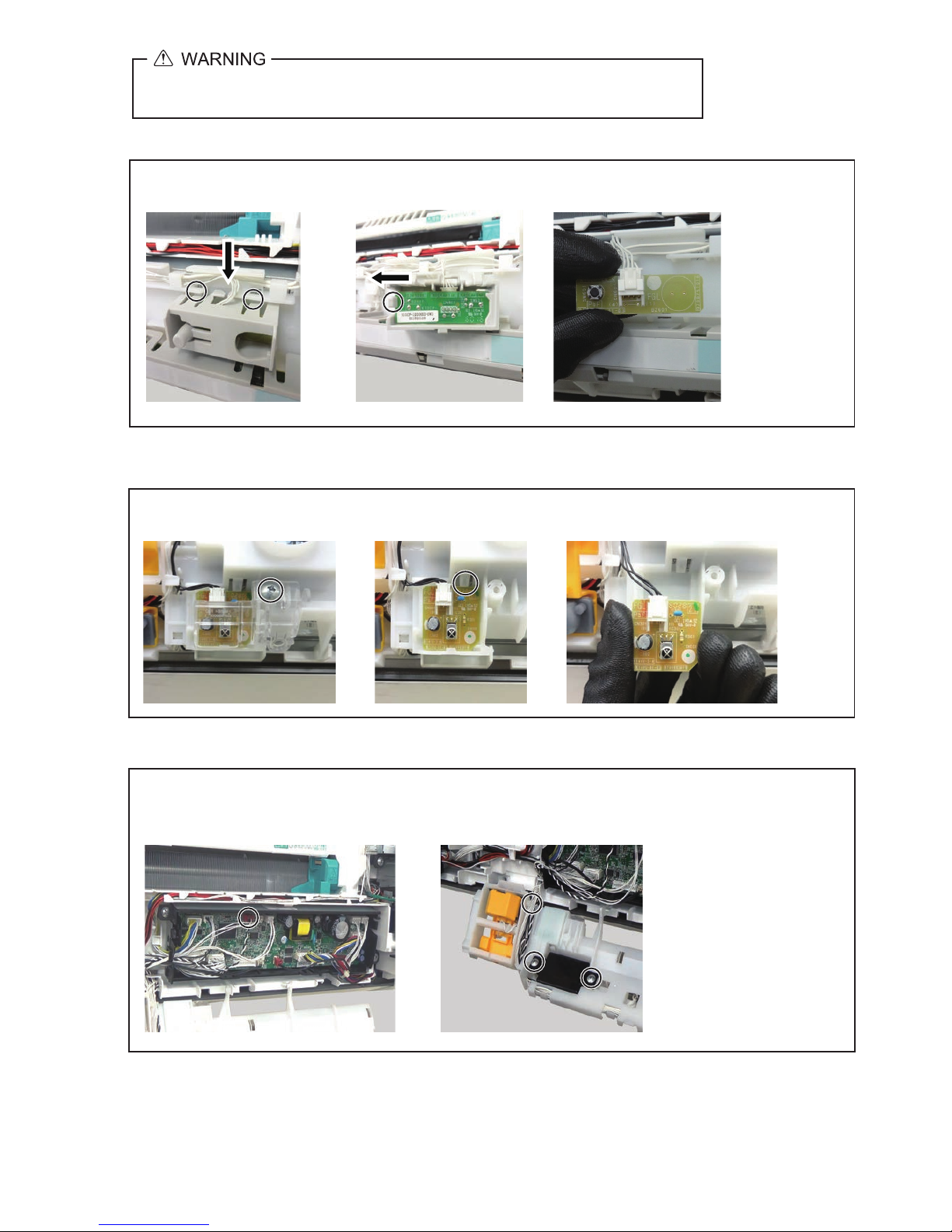
10. Switch PCB removal
1. Push the hooks. ( 2 places ) 2. Push the hook. 3. Disconnect the connector.
Start from removing the Front panel.
11. IR Receiver PCB removal
1. Remove the screw and cover. 2. Push upside supporter.
Start from removing the Front panel.
3. Disconnect the connector.
1. Disconnect the connector
of Main PCB. ( CN29 / Red )
2. Cut binder and remove the screws. ( 2 places )
Start from removing the Front panel.
12. Speaker removal
Before servicing the unit, turnings off all power supplies.
Then, do not touch the electric parts for 10 minutes due to the risk of electric shock.
04-04
Page 95

14. Grill switch removal
1. Disconnect the connector
of Main PCB. ( CN46 / White )
Start from removing Main frame.
2. Remove the hook. 3. Remove the hooks.
( 2 places )
13. Human Sensor removal
Start from opening Control box.
1. Release cables. 2. Release top shaft and bottom shaft from holder.
3. Release bottom the hooks. ( 2 places ) 4. Disconnect the connector.
Remove the screw cap and screws.
15. Under cover removal
( 3 places )
Before servicing the unit, turnings off all power supplies.
Then, do not touch the electric parts for 10 minutes due to the risk of electric shock.
04-05
There are hooks on both sides. Bend the center and remove each other.
Page 96

1. Disconnect the connector of Power PCB.
( CN3 / White )
Start from removing Front panel and Under cover.
Side fan ( Left ) removal
Mounting the Side fan ( Left )
2. Remove the screw.
3. Remove the underside hook with your right hand while supporting with the left hand.
4. Remove the screws
( 5 places ) and step motor.
Fit the black circle of the Side fan with the indoor unit.
5. Remove the Side fan panel L.
16. Side fan removal
Underside hook is reverse Side fan removing.
Before servicing the unit, turnings off all power supplies.
Then, do not touch the electric parts for 10 minutes due to the risk of electric shock.
04-06
Start from mounting Main frame.
Page 97

1. Disconnect the connector
of Power PCB. ( CN4 / White )
Start from removing Front panel and Under cover.
Side fan ( Right ) removal
Mounting the Side fan ( Right )
3. Remove the earth wire
and screw.
4. Remove the underside hook with your right hand while supporting with the left hand.
5. Remove the screws
( 5 places ) and step motor.
6. Remove the Side fan panel R.
Underside hook is reverse Side fan removing.
2. Disconnect the connector
of Filter PCB. ( CN1 / CN41 )
Before servicing the unit, turnings off all power supplies.
Then, do not touch the electric parts for 10 minutes due to the risk of electric shock.
04-07
Fit the black circle of the Side fan with the indoor unit.
Start from mounting Main frame.
Page 98

17. Main frame removal
Start from removing Side fans.
18. Limit switch removal
1. Disconnect the connector
of Main PCB. ( CN38 / White )
Start from removing main frame.
2. Remove the screws
( 3 places ) and rail cover.
3. Remove the
hook.
4. Remove the
hooks. ( 3 places )
2. Remove the screws. ( 5 places )
1. Disconnect the connectors of Main PCB. ( CN3 / CN17 / CN42 )
3. Remove the Main frame.
Tips! Do not too lift up the under port.
Before servicing the unit, turnings off all power supplies.
Then, do not touch the electric parts for 10 minutes due to the risk of electric shock.
04-08
Lift the Main frame upward, and pull toward you.
Page 99

22. Casing removal
Start from removing Side cover.
1. Remove the screws and pipe stopper. ( 2 places )
2. Remove the screws. ( 4 places )
3. Remove the casing.
Lift the Casing assy so as not to drop out from the wall bracket, then remove it diagonally downward.
Hooks ( 2 places )
Before servicing the unit, turnings off all power supplies.
Then, do not touch the electric parts for 10 minutes due to the risk of electric shock.
04-09
Page 100

19. Room temperature thermistor removal
1. Disconnect the connector
of Main PCB. ( CN4 / White )
Start from removing rail cover.
2. Remove the screw and
thermistor case.
3. Remove the Room
temperature thermistor.
21. Pipe temperature thermistor removal
Start from removing main frame.
1. Remove the screws ( 3 places )
and earth wire.
1. Disconnect the connector
of Main PCB. ( CN19 / White )
Start from removing main frame.
2. Remove the screws.
( 3 places )
3. Bend the gear unit side panel slightly.
Remove the Plasma unit.
20. Plasma unit removal
2. Remove the Side cover.
Tips!
3. Remove the Thermistor spring and
Pipe temperature thermistor.
Before servicing the unit, turnings off all power supplies.
Then, do not touch the electric parts for 10 minutes due to the risk of electric shock.
04-10
Pipe temperature thermistor can be removed without removing Side cover.
 Loading...