

Page 1
AIR CONDITIONER
Wall Mounted type
INDOOR
OUTDOOR
ASG09LLCB
ASG12LLCB
AOG09LLCB
AOG12LLCB
DESIGN & TECHNICAL MANUAL
Page 2

1.INDOOR UNIT
WALL MOUNTED TYPE :
AS
G09LLCB
AS
G12LLCB
DTR_AS070E_01
2012.08.30
Page 3

WALL MOUNTED TYPE
AS
G09-12LLCB
WALL MOUNTED TYPE
AS
G09-12LLCB
CONTENTS
1. INDOOR UNIT
1. FEATURE
.................................................................................................................. 01 - 01
2. WIRELESS REMOTE CONTROLLER
............................................... 01 - 03
3. SPECIFICATIONS
.............................................................................................. 01 - 05
4. DIMENSIONS
........................................................................................................ 01 - 06
5. WIRING DIAGRAMS
........................................................................................ 01 - 07
6. CAPACITY TABLE
............................................................................................ 01 - 08
6-1. COOLING CAPACITY
...................................................................................... 01 - 08
6-2. HEATING CAPACITY
....................................................................................... 01 - 09
7. FAN PERFORMANCE AND CAPACITY
.......................................... 01 - 10
7-1. AIR VELOCITY DISTRIBUTION
..................................................................... 01 - 10
7-2. AIR FLOW
...........................................................................................................01 - 11
8. OPERATION NOISE
......................................................................................... 01 - 13
8-1. NOISE LEVEL CURVE
.................................................................................... 01 - 13
8-2. SOUND LEVEL CHECK POINT
..................................................................... 01 - 14
9. ELECTRIC CHARACTERISTICS
........................................................... 01 - 15
10. SAFETY DEVICES
............................................................................................ 01 - 16
11. FUNCTION SETTING
...................................................................................... 01 - 17
11-1. INDOOR UNIT (Setting by remote controller)
........................................... 01 - 17
12. OPTIONAL PARTS
........................................................................................... 01 - 21
Page 4
- (01 - 01) -
WALL MOUNTED TYPE
AS
G09-12LLCB
WALL MOUNTED TYPE
AS
G09-12LLCB
FEATURE1.
MODEL
ASG09LLCB / AOG09LLCB
ASG12LLCB / AOG12LLCB
FEATURES
High EER/COP
z
High EER/COP is realized by adopting the efcient DC rotary compressor, heat exchanger, and
inverter technology. All models achieve the “Class A” ranking.
Super quiet operation
z
Top class low noise operation by new airow construction.
Our quiet operation makes the more comfortable environment
in a bed room and a study room, etc.
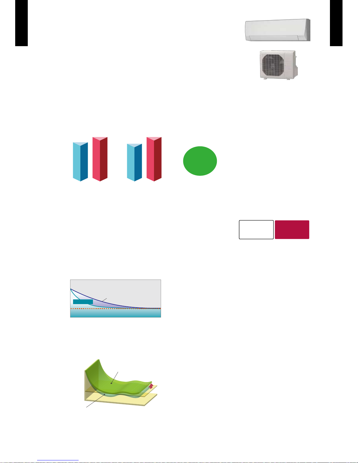
Powerful operation
z
Reach the setting temperature quickly.
Powerful
Setting
Temp.
Normal mode
Temperature
Time
(Image)
Ex. : Cooling operation
Economy operation
z
Setting temp. is shifted by 1°C automatically.
Temp.
Economy operation
Shift setting temp
Normal operation
Ex. : Cooling operation
Time
Set temperature
09 model 12 model
EER
(Cooling) (Heating) (Cooling) (Heating)
COP
3.70
3.36
EER COP
3.70
3.35
Class A
Energy saving
level
Quiet
Fan speed
22dB(A)
Noise level
Page 5

- (01 - 02) -
WALL MOUNTED TYPE
AS
G09-12LLCB
WALL MOUNTED TYPE
AS
G09-12LLCB
Easy maintenance
z
Removable & washable panel
Corresponds to maximum 15m long piping
z
Page 6

- (01 - 03) -
WALL MOUNTED TYPE
AS
G09-12LLCB
WALL MOUNTED TYPE
AS
G09-12LLCB
WIRELESS REMOTE CONTROLLER2.
FEATURES
Four kinds of timer setup
¾
(ON / OFF / PROGRAM / SLEEP) are possible.
Four kinds of timer. Easy operation.
¾
Easy to change transmission code (4 patterns) by button operation.
¾
Simple function setting
z
Setting of the air conditioner selection function is performed by remote controller.
Built-in timers
z
Select from four different timer programs (ON / OFF / PROGRAM / SLEEP).
Program timer
z
You can set a program timer, ON-OFF or OFF-ON timer suitable for your life style.
(Setting time: 0.5, 1, 1.5, 2, 2.5, -----9.5, 10, 11, 12 hours)
Example of how to set the program timer.
OFF-ON timer
From sleep to wake up
ON-OFF timer
From wake up to
go to work
OFF
10hours
ON
7hours
12
6
9
3
PM11:00
set
12
6
ON
9hours
OFF
2hours
9
3
PM9:00
set
Sleep timer
z
The sleep timer function automatically corrects the temperature thermostat setting according to
the time setting to prevent excessive cooling or heating while sleeping.
Cooling operation/dry operation
When the sleep timer is set, the set temperature
automatically rises 1 °C every hour. The set
temperature can rise up to a maximum of 2 °C.
60min.
1 °C
2 °C
Timer setting
Heating operation
When the sleep timer is set, the set temperature
automatically drops 1 °C every 30 minutes. The
set temperature can drop to a maximum of 4 °C.
1 °C
30min.
60min.
90min.
2 °C
3 °C
4 °C
Timer setting
Switching remote controller signal code
z
A B C D
A B
C
D
Mixed-up
I.U. I.U. I.U. I.U.
I.U. I.U. I.U. I.U.
After code change
Code selector switch eliminates unit
•
being wrongly switched.
(Up to 4 codes can be set.)
*I.U.=Indoor unit
Page 7
- (01 - 04) -
WALL MOUNTED TYPE
AS
G09-12LLCB
WALL MOUNTED TYPE
AS
G09-12LLCB
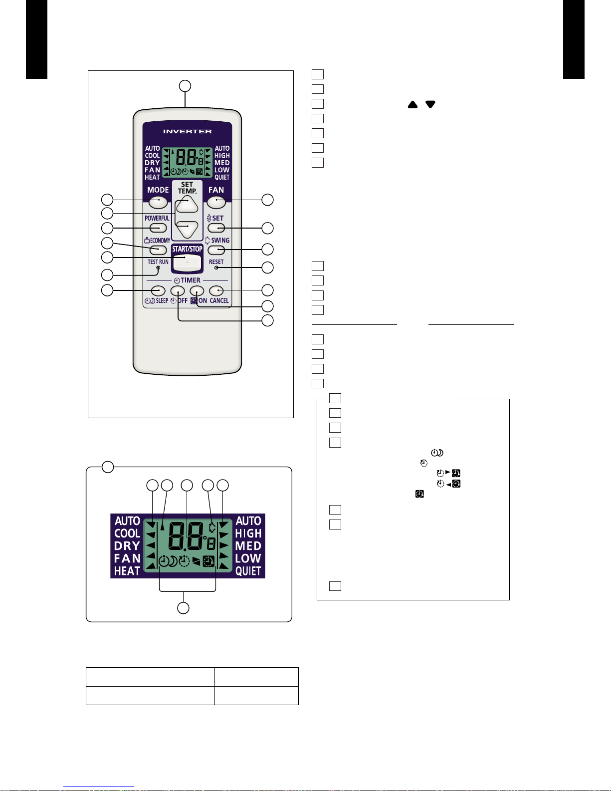
FUNCTIONS
Display panel
SPECIFICATION
2
3
5
6
7
12
13
14
8
9
10
11
15
4
1
16
19
18 17 22 20
21
SIZE (H x W x D mm) 139×56×18
WEIGHT ( g ) 70
1
Signal transmitter
2
MODE button
3
SET TEMP. button ( / )
4
POWERFUL button
5
ECONOMY button
6
START/STOP button
7
TEST RUN button
This button is used when installing the air conditioner, and
z
should not be used under normal conditions, as it will cause the
indoor unit’s thermostat function to operate inc orrectly.
If this button is pressed during normal operation, the indoor
z
unit will switch to test operation mode, and the Indoor Unit’s
OPERATION Indicator Lamp and TIMER Indicator Lamp will
begin to ash simultaneously.
To stop the test operation mode, press the START/STOP button
z
to stop the air conditioner.
8
FAN button
9
SET button
10
SWING button
11
RESET button
TIMER
12
SLEEP TIMER button
13
OFF TIMER button
14
ON TIMER button
15
TIMER CANCEL button
16
Remote controller display
17
Transmit indicator
18
Operation mode display
19
Timer mode display
SLEEP TIMER mark:
OFF TIMER mark:
OFF-ON TIMER mark:
ON-OFF TIMER mark:
ON TIMER Mark:
20
Fan speed display
21
Temperature and time display
It displays the temperature setting.
However, when making the Timer setting,
it will display the Timer time.
(The temperature setting will reappear
after nishing the timer setting)
22
Swing display
Page 8
- (01 - 05) -
WALL MOUNTED TYPE
AS
G09-12LLCB
WALL MOUNTED TYPE
AS
G09-12LLCB
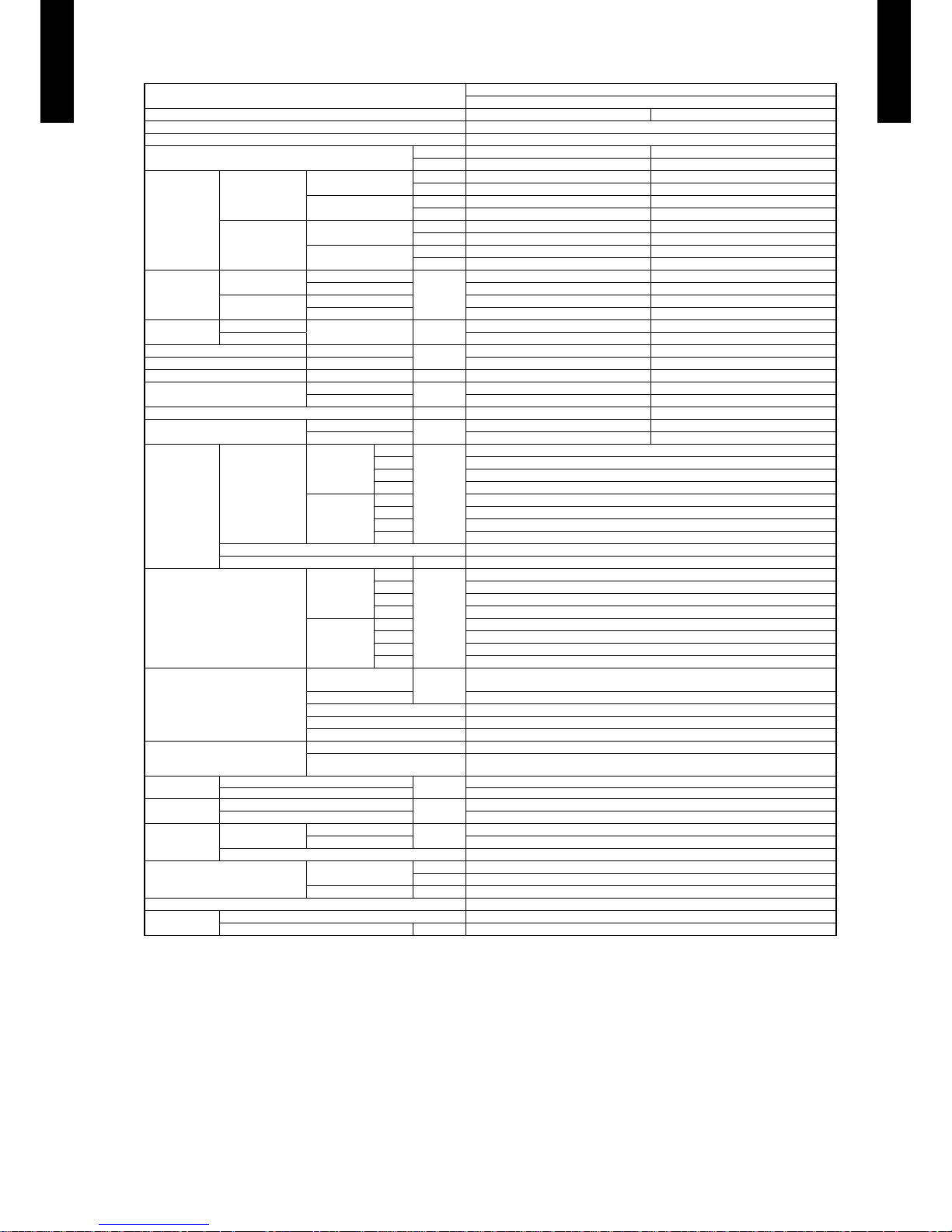
SPECIFICATIONS3.
Note :
Speci cations are base d on the foll owing conditio ns.
Coolin g:Indoor t emperat ure of 27°C C DB/ 19°C CW B.and outdoor tem peratur e of 35°C CDB / 24°C CWB.
Heating :Indoor te mperature of 20°C C DB/ 15°C CWB .and outd oor tempe rature of 7 °C CDB/ 6 °C CWB.
Pipe leng th : 5m,He ight dif ference : 0m(Outd oor unit- Indoor unit)
*1: The maximu m curre nt is the ma ximum valu e when the o perated w ithin th e operati on range.
Type
WALL MOUNTED
INVERTER HEAT PUMP
Model name AS¾G09LLCB AS¾G12LLCB
Power source 230V~ 50Hz
Available voltage range 198-264V~ 50Hz
European energy label
Cooling A A
Heating A A
Capacity
Cooling
Rated
kW 2.50 3.40
Btu/h 8,500 11,600
Min-Max
kW 0.9 - 3.0 0.9-3.8
Btu/h 3,100 - 10,200 3,100-13,000
Heating
Rated
kW 3.20 4.00
Btu/h 10,900 13,600
Min-Max
kW 0.9 - 3.6 0.9-4.6
Btu/h 3,100 - 12,300 3,100-15,700
Input power
Cooling
Rated
kW
0.745 1.015
Min-Max 0.24 - 1.06 0.23 - 1.30
Heating
Rated 0.865 1.080
Min-Max 0.21 - 1.00 0.21 - 1.84
Current
Cooling
Rated A
4.0 4.7
Heating 4.7 5.1
EER Cooling
kW/kW
3.36 3.35
COP Heating 3.70 3.70
SENSIBLE CAPACITY Cooling kW 1.6 2.2
POWER FACTOR
Cooling
%
81 94
Heating 80 92
Moisture removal l/h (pints/h) 1.3 (2.3) 1.8 (3.2)
Maximum operating current *1
Cooling
A
6.0 7.0
Heating 6.0 9.5
Fan
Air ow rate
Cooling
High
m
3
/h
720
Med 600
Low 420
Quiet 325
Heating
High 740
Med 600
Low 450
Quiet 325
Type × Q'ty Cross ow fan × 1
Motor output W 30
Sound pressure level
Cooling
High
dB(A)
43
Med 38
Low 33
Quiet 22
Heating
High 43
Med 38
Low 33
Quiet 22
Heat exchanger type
Dimensions
(H × W × D)
mm
256 × 630 × 20
Fin pitch 1.1
Rows Stages 2 × 16
Pipe type Copper
Fin type Aluminium
Enclosure
Material Polystyrene
Colour
WHITE
Approximate colour of MUNSELL N 9.25/
Dimensions
(H × W × D)
Net
mm
262 × 820 × 206
Gross 263 × 870 × 328
Weight
Net
kg
7.5
Gross 9.5
Connection pipe
Size
Liquid
mm
Φ6.35 (Φ1/4 in)
Gas Φ9.52 (Φ3/8 in)
Method Flare
Operation range
Cooling
°C 18 to 32
%RH 80 or less
Heating °C 16 to 30
Remote controller type Wireless
Drain hose
Material PP+LLDPE
Size mm Ø13.8(I.D.), Ø15.8 to Ø16.7(O.D.)
Page 9
- (01 - 06) -
WALL MOUNTED TYPE
AS
G09-12LLCB
WALL MOUNTED TYPE
AS
G09-12LLCB
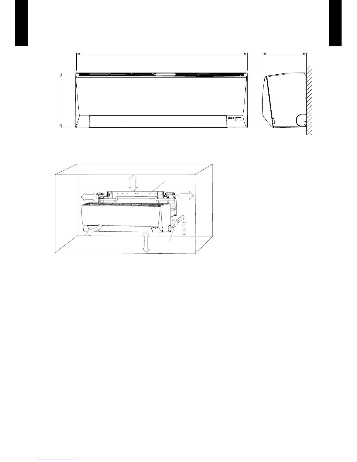
DIMENSIONS4.
MODEL : ASG09LLCB, ASG12LLCB
(Unit : mm)
262
206820
INSTALLATION PLACE
70 mm or more
1,500 mm or more
1,800 mm or more
(Wall cap)
63 mm or more
Wall hook bracket
100 mm or more
Page 10
- (01 - 07) -
WALL MOUNTED TYPE
AS
G09-12LLCB
WALL MOUNTED TYPE
AS
G09-12LLCB
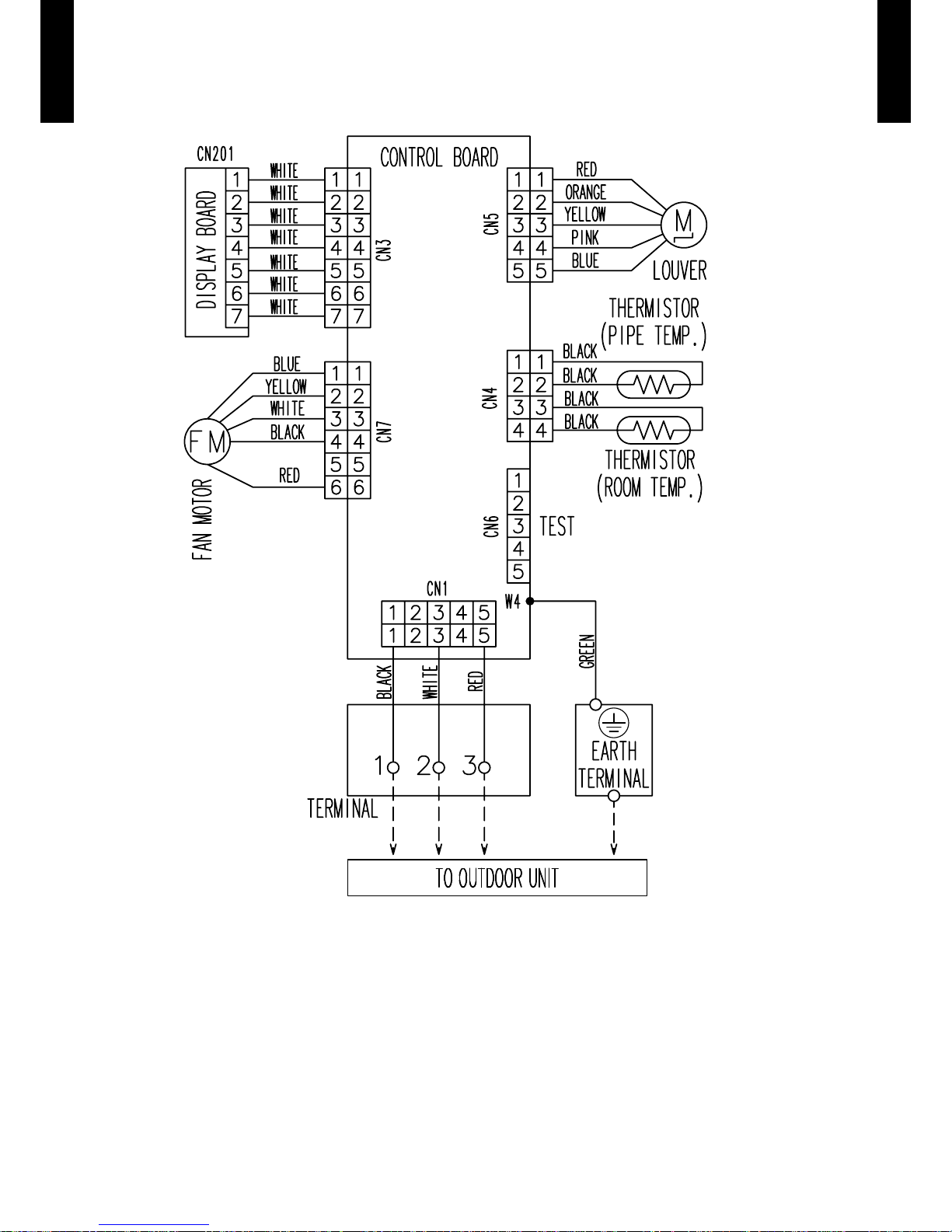
WIRING DIAGRAMS5.
MODEL : ASG09LLCB, ASG12LLCB
Page 11
- (01 - 08) -
WALL MOUNTED TYPE
AS
G09-12LLCB
WALL MOUNTED TYPE
AS
G09-12LLCB
CAPACITY TABLE6.
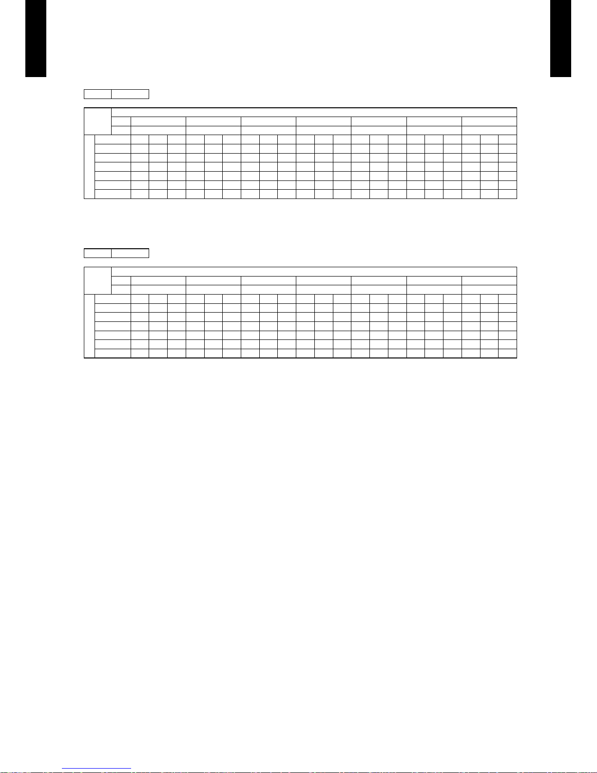
COOLING CAPACITY6-1.
MODEL : ASG09LLCB
MODEL : ASG12LLCB
AFR: Air F low Rate (m³/m in.)
TC: Total Capaci ty (kW)
SHC: Sens ible Hea t Capacit y (kW)
IP: Input Po wer (kW)
AFR 12.0
Indoor temperature
°CDB 18 21 23 25 27 29 32
°CWB 12 15 16 18 19 21 23
Outdoor temperature
°CDB TC SHC IP TC SHC IP TC SHC IP TC SHC IP TC SHC IP TC SHC IP TC SHC IP
20 2.27 1.55 0.51 2.40 1.64 0.51 2.71 1.85 0.57 2.80 1.92 0.60 2.91 1.99 0.61 3.03 2.07 0.60 3.15 2.15 0.61
25 2.15 1.61 0.58 2.28 1.61 0.57 2.56 1.61 0.65 2.67 1.61 0.66 2.77 1.61 0.67 2.88 1.61 0.68 2.99 1.61 0.69
30 2.00 1.37 0.63 2.10 1.44 0.61 2.35 1.61 0.68 2.49 1.71 0.69 2.62 1.80 0.71 2.70 1.85 0.70 2.78 1.91 0.69
35 1.85 1.44 0.69 1.93 1.44 0.65 2.14 1.44 0.70 2.31 1.44 0.73 2.50 1.60 0.75 2.53 1.44 0.72 2.58 1.44 0.69
40 1.60 1.09 0.63 1.68 1.15 0.61 1.88 1.28 0.65 2.01 1.37 0.66 2.15 1.46 0.66 2.23 1.52 0.65 2.32 1.58 0.63
43 1.35 1.06 0.57 1.44 1.06 0.57 1.63 1.06 0.59 1.72 1.06 0.59 1.82 1.06 0.58 1.94 1.06 0.58 2.06 1.06 0.57
AFR 12.0
Indoor temperature
°CDB 18 21 23 25 27 29 32
°CWB 12 15 16 18 19 21 23
Outdoor temperature
°CDB TC SHC IP TC SHC IP TC SHC IP TC SHC IP TC SHC IP TC SHC IP TC SHC IP
20 2.66 1.84 0.55 3.09 2.14 0.65 3.57 2.47 0.77 3.75 2.59 0.78 3.92 2.72 0.79 4.06 2.81 0.79 4.19 2.90 0.79
25 2.54 1.75 0.64 2.94 2.03 0.74 3.40 2.35 0.87 3.56 2.46 0.88 3.73 2.57 0.89 3.86 2.66 0.90 3.99 2.75 0.90
30 2.54 1.76 0.81 2.84 1.96 0.87 3.18 2.20 0.94 3.37 2.34 0.97 3.56 2.47 0.99 3.70 2.56 0.99 3.83 2.65 0.99
35 2.55 1.76 0.98 2.73 1.89 0.99 2.97 2.05 1.02 3.18 2.20 1.06 3.40 2.20 1.02 3.53 2.44 1.09 3.67 2.53 1.08
40 2.26 1.56 0.95 2.43 1.68 0.96 2.66 1.84 0.98 2.84 1.96 0.99 3.02 2.09 1.01 3.18 2.20 1.01 3.34 2.31 1.01
43 1.97 1.37 0.91 2.14 1.48 0.93 2.35 1.63 0.93 2.49 1.73 0.93 2.64 1.83 0.92 2.83 1.96 0.93 3.02 2.09 0.94
Page 12
- (01 - 09) -
WALL MOUNTED TYPE
AS
G09-12LLCB
WALL MOUNTED TYPE
AS
G09-12LLCB
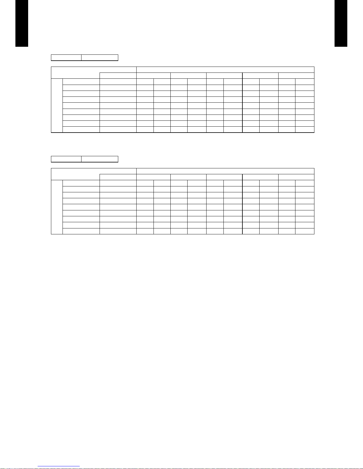
HEATING CAPACITY6-2.
MODEL : AS
G09LLCB
MODEL : AS
G12LLCB
AFR: Air F low Rate (m³/mi n.)
TC: Total Capaci ty (kW)
IP: Input Po wer (kW)
AFR 12.3
Indoor temperature
°CDB 16 18 20 22 24
Outdoor temperature
°CDB °CWB TC IP TC IP TC IP TC IP TC IP
-15 -16 2.37 0.97 2.15 0.97 1.93 0.96 1.89 0.97 1.84 0.9 8
-10 -11 2.35 0.98 2.27 0.98 2.18 0.98 2.21 0.99 2.24 1.00
-5 -7 2.60 1.00 2.52 1.00 2.43 1.00 2.49 1.00 2.5 4 1.00
0 -2 2.87 1.00 2.97 1.01 3.07 1.01 2.98 1.01 2.88 1.01
5 3 3.29 1.01 3.31 1.01 3.34 1.01 3. 24 1.03 3.15 1.06
7 6 3.70 1.01 3.65 1.01 3.6 0 1.00 3.51 1.05 3.41 1.10
10 8 3.83 0.99 3.77 0.99 3.71 0.99 3.62 1.01 3.53 1.04
15 10 3.95 0.97 3.89 0.97 3.82 0.97 3.73 0.97 3.64 0.97
AFR 12.3
Indoor temperature
°CDB 16 18 20 22 24
Outdoor temperature
°CDB °CWB TC IP TC IP TC IP TC IP TC IP
-15 -16 3.01 1.5 4 3.04 1.57 3.07 1.59 3.04 1.58 3.00 1.57
-10 -11 3.73 1.6 4 3.6 8 1.66 3.62 1.68 3.59 1.71 3.56 1.73
-5 -7 4.26 1.75 4.24 1.79 4.22 1.82 4.18 1.87 4 .13 1. 92
0 -2 4.94 1.9 5 4.89 1.96 4.83 1.97 4.70 1.97 4.56 1.97
5 3 5.12 1.90 4.92 1.91 4.72 1.91 4.74 1.91 4.77 1.91
7 6 5.30 1.8 5 4.95 1.85 4.60 1.84 4.79 1.85 4.98 1.85
10 8 5.35 1.72 5.13 1.72 4.91 1.72 4.95 1.72 4.98 1.72
15 10 5.39 1.5 9 5.31 1.59 5.22 1.59 5.10 1.59 4.98 1.58
Page 13

- (01 - 10) -
WALL MOUNTED TYPE
AS
G09-12LLCB
WALL MOUNTED TYPE
AS
G09-12LLCB
FAN PERFORMANCE AND CAPACITY7.
AIR VELOCITY DISTRIBUTION7-1.
MODEL : ASG09LLCB, ASG12LLCB
Note:
Fan speed: High
Operation mode: Fan
2.0
1.0
0.5
2
1
0
1
2
Unit : m/s(m)
(m)
TOP VIEW
Vertic al ap : Up
Horizo ntal ap : C enter
0 1 2 3 4 5 6 7 8
2.0
1.0
1.0
0.5
0.5
3
2
1
0
1
2
3
Unit : m/s(m)
TOP VIEW
Vertic al ap : Up
Horizo ntal ap : R ight & Lef t
(m)
0 1 2 3 4 5 6 7 8
2.0
1.0
0.5
3
2
1
0
Unit : m/s(m)
SIDE VIE W
Vertic al ap : Up
Horizo ntal ap : C enter
(m)
0 1 2 3 4 5 6 7 8
2.0
1.0
0.5
3
2
1
0
Unit : m/s(m)
SIDE VIE W
Vertic al ap : Dow n
Horizo ntal ap : C enter
(m)
0 1 2 3 4 5 6 7 8
Page 14

- (01 - 11) -
WALL MOUNTED TYPE
AS
G09-12LLCB
WALL MOUNTED TYPE
AS
G09-12LLCB
AIR FLOW7-2.
MODEL : ASG09LLCB
Cooling
z
z
Heating
Fan speed
Number of
rotations
(r.p.m)
Air ow
HIGH 1320
720 m³/h
200 l/s
424 CFM
MED 112 0
600 m³/h
167 l/s
353 CFM
LOW 840
420 m³/h
117 l/s
247 CFM
QUIET 700
325 m³/h
90 l/s
191 CFM
Fan speed
Number of
rotations
(r.p.m)
Air ow
HIGH 13 60
740 m³/h
206 l/s
436 CFM
MED 112 0
600 m³/h
167 l/s
353 CFM
LOW 900
450 m³/h
125 l/s
265 CFM
QUIET 700
325 m³/h
90 l/s
191 CFM
Page 15

- (01 - 12) -
WALL MOUNTED TYPE
AS
G09-12LLCB
WALL MOUNTED TYPE
AS
G09-12LLCB
MODEL : ASG12LLCB
Cooling
z
z
Heating
Fan speed
Number of
rotations
(r.p.m)
Air ow
HIGH 1320
720 m³/h
200 l/s
424 CFM
MED 112 0
600 m³/h
167 l/s
353 CFM
LOW 860
425 m³/h
118 l/s
250 CFM
QUIET 700
325 m³/h
90 l/s
191 CFM
Fan speed
Number of
rotations
(r.p.m)
Air ow
HIGH 13 60
740 m³/h
206 l/s
436 CFM
MED 112 0
600 m³/h
167 l/s
353 CFM
LOW 900
450 m³/h
125 l/s
265 CFM
QUIET 700
325 m³/h
90 l/s
191 CFM
Page 16

- (01 - 13) -
WALL MOUNTED TYPE
AS
G09-12LLCB
WALL MOUNTED TYPE
AS
G09-12LLCB
OPERATION NOISE8.
NOISE LEVEL CURVE8-1.
MODEL : ASG09LLCB
High
Quiet
High
Quiet
High
Quiet
High
Quiet
Cooling
z
Octave ba nd sound p ressur e level, dB:(0 dB= 0.0002µbar)
Octave ba nd cente r freque ncy,Hz
80
70
60
50
40
30
20
10
0
63 125 250 5 00 1,00 0 2,00 0 4,000 8 ,000
NC-65
NC-60
NC-55
NC-50
NC-45
NC-40
NC-35
NC-30
NC-25
NC-20
NC -15
Heating
z
Octave ba nd sound p ressur e level, dB:(0 dB= 0.0002µbar)
Octave ba nd cente r freque ncy,Hz
80
70
60
50
40
30
20
10
0
63 125 250 5 00 1,00 0 2,00 0 4,000 8 ,000
NC-65
NC-60
NC-55
NC-50
NC-45
NC-40
NC-35
NC-30
NC-25
NC-20
NC -15
NC-65
NC-60
NC-55
NC-50
NC-45
NC-40
NC-35
NC-30
NC-25
NC-20
NC -15
Octave ba nd sound p ressur e level, dB:(0 dB= 0.0002µbar)
Octave ba nd cente r freque ncy,Hz
80
70
60
50
40
30
20
10
0
63 125 250 5 00 1,00 0 2,00 0 4,000 8 ,000
MODEL : ASG12LLCB
Cooling
z
Heating
z
Octave ba nd sound p ressur e level, dB:(0 dB= 0.0002µbar)
Octave ba nd cente r freque ncy,Hz
80
70
60
50
40
30
20
10
0
63 125 250 5 00 1,00 0 2,00 0 4,000 8 ,000
NC-65
NC-60
NC-55
NC-50
NC-45
NC-40
NC-35
NC-30
NC-25
NC-20
NC -15
Page 17

- (01 - 14) -
WALL MOUNTED TYPE
AS
G09-12LLCB
WALL MOUNTED TYPE
AS
G09-12LLCB
SOUND LEVEL CHECK POINT8-2.
Page 18

- (01 - 15) -
WALL MOUNTED TYPE
AS
G09-12LLCB
WALL MOUNTED TYPE
AS
G09-12LLCB
ELECTRIC CHARACTERISTICS9.
Model Name ASG09LLCB ASG12LLCB
Power Supply
Voltage V 230 ~
Frequency Hz 50
Max. Operating Current A 0.3
*)Wiring Spec
Connection Cable mm
2
1.5
Limited wiring length m 21
*) Wiring S pec
Select ed Sample
(Selecte d based on J apan Elec trotec hnical S tandar d and Code s Commit tee E0005)
Page 19

- (01 - 16) -
WALL MOUNTED TYPE
AS
G09-12LLCB
WALL MOUNTED TYPE
AS
G09-12LLCB
SAFETY DEVICES10.
Protection form
Model
ASG09LLCB ASG12LLCB
Circuit protection Current fuse (PCB) 250V 3.15A
Fan motor protection Terminal protection program
OFF: 160 ± 25 °C
ON: 110 ± 25 °C
Page 20

- (01 - 17) -
WALL MOUNTED TYPE
AS
G09-12LLCB
WALL MOUNTED TYPE
AS
G09-12LLCB
FUNCTION SETTING11.
INDOOR UNIT (Setting by remote controller)11-1.
The function settings of the control of the indoor unit can be changed by this procedure according •
to the installation conditions. Incorrect settings can cause the indoor unit malfunction.
After the power is turned on, perform the “FUNCTION SETTING” according to the installation •
conditions using the remote controller.
The settings may be selected between the following two: Function Number or Setting Value. •
Settings will not be changed if invalid numbers or setting values are selected. •
PREPARATION
Turn on the power •
* By turning on the power indoor units, so make sure the piping air-tight test and vacuuming have been conducted
before turning on the power.
* Also check again to make sure no wiring mistakes were made before turning on the power.
FUNCTION SETTING METHOD (for Wireless remote controller)
Entering the Function Setting Mode
While pressing the FAN button and SET TEMP. (
•
) button simultaneously, press the RESET button to enter the
function setting mode.
STEP 1
Setting the Remote controller Signal Code
Use the following steps to select the signal code of the remote controller. (Note
that the air conditioner cannot receive a signal code if the air conditioner has not
been set for the signal code.) The signal code that is set through this process are
applicable only to the signal in the FUNCTION SETTING. For details on how to set
the signal code through the normal process, refer to SELECTING THE REMOTE
CONTROLLER SIGNAL CODE.
Press the SET TEMP. (1.
) ( ) button to change the signal code between →
→
→ Match the code on the display to the air conditioner signal code. (initially
set to
)
(If the signal code does not need to be selected, press the MODE button and
proceed to STEP 2.)
Press the MODE button to accept the signal code, and proceed to STEP 2.2.
*1
The air conditioner signal code is set to prior to shipment.
Contact your retailer to change the signal code.
The remote controller resets to signal code when the batteries in the remote controller are replaced. If you use a
signal code other than signal code
, reset the signal code after replacing the batteries.
If you do not know the air conditioner signal code setting, try each of the signal codes (
→ → → ) until you
nd the code which operates the air conditioner.
STEP 2
Selecting the Function Number and Setting Value
Press the SET TEMP. (1.
) ( ) buttons to select the function number.
(Press the MODE button to switch between the left and right digits.)
Press the FAN button to proceed to setting the value. 2.
(Press the FAN button again to return to the function number
selection.)
Press the SET TEMP. (3.
) ( ) buttons to select the setting value.
(Press the MODE button to switch between the left and right digits.)
Press the SLEEP button, then after you hear the beep emitted from 4.
the indoor unit, press the START/STOP button to conrm the settings.
Press the RESET button to cancel the function setting mode.5.
After completing the FUNCTION SETTING, be sure to turn off the 6.
power and turn it on again.
Function number
Setting value
*1
*1
CAUTION
After turning off the power, wait 10 seconds or more before turning on it again.
The FUNCTION SETTING doesn’t become effective if it doesn’t do so.
Note :
*1) Small "A" is displayed on the right of the signal code during the FUNCTION SETTING.
Page 21

- (01 - 18) -
WALL MOUNTED TYPE
AS
G09-12LLCB
WALL MOUNTED TYPE
AS
G09-12LLCB
FUNCTION DETAILS
Functions
Compact wall
mounted
1) Filter sign
z
2) Cooler room temperature correction
z
3) Heater room temperature correction
z
4) Auto restart
z
5) Remote controller signal code
z
1) Filter sign
The indoor unit has a sign to inform the user that it is time to clean the lter. Select the time
setting for the lter sign display interval in the table below according to the amount of dust or
debris in the room. If you do not wish the lter sign to be displayed, select the setting value for
"No indication".
(... Factory setting)
Setting description Function number Setting value
Standard
11
00
Long interval 01
Short interval 02
No indication 03
The lter sign interval time is different according to Indoor unit type as follows.
Setting description
Compact Wall
Mounted
Standard 400 hours
Long interval 1000 hours
Short interval 200 hours
2) Cooler room temperature correction
Depending on the installed environment, the room temperature sensor may require a
correction.
The settings may be selected as shown in the table below.
(... Factory setting)
Setting description Function number Setting value
Standard
30
00
Slightly lower control 01
Lower control 02
Warmer control 03
3) Heater room temperature correction
Depending on the installed environment, the room temperature sensor may require a
correction.
The settings may be changed as shown in the table below.
(... Factory setting)
Setting description Function number Setting value
Standard
31
00
Lower control 01
Slightly warmer control 02
Warmer control 03
Page 22

- (01 - 19) -
WALL MOUNTED TYPE
AS
G09-12LLCB
WALL MOUNTED TYPE
AS
G09-12LLCB
4) Auto restart
Enable or disable automatic system restart after a power outage.
(... Factory setting)
Setting description Function number Setting value
Yes
40
00
No 01
* Auto restart is an emergency function such as for power failure etc.
Do not start and stop the indoor unit by this function in normal operation.
Be sure to operate by the control unit, or external input device.
5) Remote controller signal code
Change the indoor unit Signal Code, depending on the remote controllers.
(... Factory setting)
Setting description Function number Setting value
A
44
00
B 01
C 02
D 03
Page 23

- (01 - 20) -
WALL MOUNTED TYPE
AS
G09-12LLCB
WALL MOUNTED TYPE
AS
G09-12LLCB
REMOTE CONTROLLER SIGNAL CODE SETTING
Use the following steps to select the signal code of the remote controller.
(Note that the air conditioner cannot receive a signal code if the air conditioner has
not been set for the signal code.)
Press the MODE button for at least ve seconds to display the current signal code 1.
(initially set to
).
Press the SET TEMP. (2.
) ( ) button to change the signal code between →
→
→ .
Match the code on the display to the air conditioner signal code.
Press the MODE button again. The signal code will be changed.3.
If no buttons are pressed within 30 seconds after the signal code is displayed, the display returns to the original
status. In this case, start again from step 1.
The air conditioner signal code is set to A prior to shipment.
Contact your retailer to change the signal code.
The remote controller resets to signal code A when the batteries in the remote controller are replaced. If you use
a signal code other than signal code A, reset the signal code after replacing the batteries. If you do not know the
air conditioner signal code setting, try each of the signal codes (
→ → → ) until you nd the code which
operates the air conditioner.
Page 24

- (01 - 21) -
WALL MOUNTED TYPE
AS
G09-12LLCB
WALL MOUNTED TYPE
AS
G09-12LLCB
OPTIONAL PARTS12.
Exterior Parts name Model No. Summary
Remote
controller
holder
UT Z- RXLA
Wall or pillar mountable, and
holds the remote controller.
Page 25

2.OUTDOOR UNIT
SINGLE TYPE :
AO
G09LLCB
AO
G12LLCB
DTR_AO122E_01
2012.08.30
Page 26

OUTDOOR UNIT
AO
G09-12LLCB
OUTDOOR UNIT
AO
G09-12LLCB
CONTENTS
2. OUTDOOR UNIT
1. SPECIFICATIONS
.............................................................................................. 02 - 01
2. DIMENSIONS
........................................................................................................ 02 - 02
3. REFRIGERANT CIRCUIT
............................................................................ 02 - 03
4. WIRING DIAGRAMS
........................................................................................ 02 - 05
5. CAPACITY COMPENSATION RATE FOR PIPE LENGTH AND
HEIGHT DIFERENCE
...................................................................................... 02 - 06
6. ADDITIONAL CHARGE CALCULATION
......................................... 02 - 08
7. AIR FLOW
................................................................................................................ 02 - 09
8. OPERATION NOISE
......................................................................................... 02 - 10
8-1. NOISE LEVEL CURVE
.................................................................................... 02 - 10
8-2. SOUND LEVEL CHECK POINT
......................................................................02 - 11
9. ELECTRIC CHARACTERISTICS
........................................................... 02 - 12
10. SAFETY DEVICES
............................................................................................ 02 - 13
Page 27

- (02 - 01) -
OUTDOOR UNIT
AO
G09-12LLCB
OUTDOOR UNIT
AO
G09-12LLCB
SPECIFICATIONS1.
Note :
Speci cations are base d on the foll owing conditio ns.
Coolin g : Indoor te mperat ure of 27 °CD B / 19 °CWB.an d outdoo r tempera ture of 35 °C DB / 24 °CWB .
Heating : I ndoor te mperatu re of 20 °CD B / 15 °CWB.an d outdoor t emperat ure of 7 °CD B / 6 °CWB.
Pipe leng th : 5 m, Heig ht diffe rence : 0 m.(O utdoor un it - Indoo r unit)
The prote ctive fu nction m ight work w hen usin g it outsid e the oper ation ra nge.
Typ e INVERT ER COOLI NG & HEATING
Model na me AOÛG09L LCB AOÛG12LLC B
Power sour ce 230V~ 50 Hz
Available v oltage r ange 198 -264V~ 50Hz
Start ing current A 4.7 5.1
Fan
Air ow ra te
Cooling
m
3
/h
1,710 1,850
Heating 1,680 1,8 20
Type × Q'ty Pr opelle r fan × 1
Motor out put W 26
Sound pre ssure leve l
Cooling
dB(A)
47 51
Heating 48 52
Heat excha nger typ e
Dimensi ons (H × W × D)
mm
650 × 50 4 × 18.2
650 × 50 4 × 18.2
350 × 50 4 × 18.2
Fin pitch 1.4 1.4
Rows x Stag es 1 × 24 1.5 × 24
Pipe typ e Copper
Fin type Aluminium
Compressor
Type × Q'ty Rotar y × 1
Motor out put W 700 70 0
Refrig erant
Typ e R410 A
Charge g 6 50 750
Refrig erant oil Typ e POE (VG 74)
Enclosu re
Material Steel
Colour
BEIGE
Approxi mate col our of MUN SELL 10YR 7.5/1.0
Dimensions
( H × W × D)
Net
mm
535 × 66 3 × 293 535 × 66 3 × 293
Gross 5 90 × 790 × 3 95 590 × 790 × 3 95
Weight
Net
kg
24 26
Gross 27 28
Connec tion pip e
Size
Liquid
mm
Φ6.35 (Φ 1/4 in.)
Gas Φ9 .52 (Φ 3/8 in.)
Method Flare
Pre- charge l ength
m
10
Max. len gth 15
Max. hei ght dif ferenc e 10
Operat ion rang e
Cooling
°C
18 to 43
Heating -15 to 24
Page 28

- (02 - 02) -
OUTDOOR UNIT
AO
G09-12LLCB
OUTDOOR UNIT
AO
G09-12LLCB
INSTALLATION PLACE
If the space is larger that is stated, the condition will be the same as that are no obstacles.
600 mm or more
100 mm or more
200 mm or more
100 mm or more
250 mm or more
(Service space)
•
•
CAUTION
When the outdoor temperature is 0 °C or
less, do not use the accessory drain pipe
and drain cap. If the drain pipe and drain cap
are used, the drain water in the pipe may
freeze in extremely cold weather. (Reverse
cycle model only)
In the area with heavy snowfall, if the intake
and outlet of outdoor unit is blocked with
snow, it might become difficult to get warm
and it is likely to cause of the breakdown.
Please construct a canopy and a pedestal or
place the unit on a high stand (local
configured).
DIMENSIONS2.
MODEL : AOG09LLCB, AOG12LLCB
(Unit : mm)
Page 29

- (02 - 03) -
OUTDOOR UNIT
AO
G09-12LLCB
OUTDOOR UNIT
AO
G09-12LLCB
REFRIGERANT CIRCUIT3.
MODEL : AOG09LLCB
Refrigerant pipe diameter
Liquid : 1/4" (6.35 mm)
Gas : 3/8" (9.52 mm)
Page 30

- (02 - 04) -
OUTDOOR UNIT
AO
G09-12LLCB
OUTDOOR UNIT
AO
G09-12LLCB
MODEL : AOG12LLCB
Refrigerant pipe diameter
Liquid : 1/4" (6.35 mm)
Gas : 3/8" (9.52 mm)
Page 31

- (02 - 05) -
OUTDOOR UNIT
AO
G09-12LLCB
OUTDOOR UNIT
AO
G09-12LLCB
WIRING DIAGRAMS4.
MODEL : AOG09LLCB, AOG12LLCB
Page 32

- (02 - 06) -
OUTDOOR UNIT
AO
G09-12LLCB
OUTDOOR UNIT
AO
G09-12LLCB
CAPACITY COMPENSATION RATE FOR PIPE LENGTH 5.
AND HEIGHT DIFERENCE
MODEL : AOG09LLCB
Height difference H
1 Indoor unit is upper than outdoor unit.
2 Indoor unit is under than outdoor unit.
Indoor unit
Indoor unit
Connection pipe
Outdoor unit
Outdoor unit
Connection pipe
HEATING
Pipe length (m)
5 7.5 10 15
Height difference H
(m)
Û
1
Indoor unit is upper
than outdoor unit.
10 - - 0.944 0.897
7. 5 - 0.983 0.944 0.897
5 1.000 0.983 0.944 0.897
0 1.000 0.983 0.944 0.897
Û
2
Indoor unit is under
than outdoor unit
-5 0.995 0.978 0.939 0.892
-7. 5 - 0.976 0.937 0.891
-10 - - 0.935 0.889
COOLING
Pipe length (m)
5 7.5 10 15
Height difference H
(m)
Û
1
Indoor unit is upper
than outdoor unit.
10 - - 0.980 0.944
7. 5 - 0.988 0.984 0.948
5 0.992 0.992 0.988 0.951
0 1.000 1.000 0.995 0.960
Û
2
Indoor unit is under
than outdoor unit
-5 1.000 1.000 0.995 0.960
-7. 5 - 1.000 0.995 0.960
-10 - - 0.995 0.960
Page 33

- (02 - 07) -
OUTDOOR UNIT
AO
G09-12LLCB
OUTDOOR UNIT
AO
G09-12LLCB
MODEL : AOG12LLCB
Height difference H
1 Indoor unit is upper than outdoor unit.
2 Indoor unit is under than outdoor unit.
Indoor unit
Indoor unit
Connection pipe
Outdoor unit
Outdoor unit
Connection pipe
HEATING
Pipe length (m)
5 7.5 10 15
Height difference H
(m)
Û
1
Indoor unit is upper
than outdoor unit.
10 - - 0.908 0.875
7. 5 - 0.954 0.908 0.875
5 1.000 0.954 0.908 0.875
0 1.000 0.954 0.908 0.875
Û
2
Indoor unit is under
than outdoor unit
-5 0.995 0.949 0.903 0.870
-7. 5 - 0.947 0.902 0.868
-10 - - 0.900 0.867
COOLING
Pipe length (m)
5 7.5 10 15
Height difference H
(m)
Û
1
Indoor unit is upper
than outdoor unit.
10 - - 0.957 0.911
7. 5 - 0.974 0.961 0.916
5 0.992 0.978 0.965 0.919
0 1.000 0.986 0.972 0.927
Û
2
Indoor unit is under
than outdoor unit
-5 1.000 0.986 0.972 0.927
-7. 5 - 0.986 0.972 0.927
-10 - - 0.972 0.927
Page 34

- (02 - 08) -
OUTDOOR UNIT
AO
G09-12LLCB
OUTDOOR UNIT
AO
G09-12LLCB
ADDITIONAL CHARGE CALCULATION6.
MODEL : AOG09LLCB
Refrigerant charge
z
MODEL : AOG12LLCB
Refrigerant charge
z
Refrigerant type R410 A
Refrigerant amount g 650
Total pipe length m 10 or less 15 (MAX)
20g/m
Additional charge g 0 100
Refrigerant type R410 A
Refrigerant amount g 750
Total pipe length m 10 or less 15 (MAX)
20g/m
Additional charge g 0 100
Page 35

- (02 - 09) -
OUTDOOR UNIT
AO
G09-12LLCB
OUTDOOR UNIT
AO
G09-12LLCB
AIR FLOW7.
MODEL : AOG09LLCB
Cooling
z
Heating
z
MODEL : AOG12LLCB
Cooling
z
Heating
z
Number of
rotations
(r.p.m.)
Air ow
740
1710 m
3
/h
475 l/s
1007 CFM
Number of
rotations
(r.p.m.)
Air ow
730
1680 m
3
/h
467 l/s
989 CFM
Number of
rotations
(r.p.m.)
Air ow
820
1850 m
3
/h
514 l/s
1089 CFM
Number of
rotations
(r.p.m.)
Air ow
810
1820 m
3
/h
506 l/s
1071 CFM
Page 36

- (02 - 10) -
OUTDOOR UNIT
AO
G09-12LLCB
OUTDOOR UNIT
AO
G09-12LLCB
OPERATION NOISE8.
NOISE LEVEL CURVE8-1.
MODEL : AOG09LLCB
MODEL : AOG12LLCB
Cooling
z
Cooling
z
Octave ba nd sound p ressur e level, dB:(0 dB= 0.0002µbar)
Octave ba nd cente r freque ncy,Hz
80
70
60
50
40
30
20
10
0
63 125 250 5 00 1,00 0 2,00 0 4,000 8 ,000
NC-65
NC-60
NC-55
NC-50
NC-45
NC-40
NC-35
NC-30
NC-25
NC-20
NC -15
Heating
z
Octave ba nd sound p ressur e level, dB:(0 dB= 0.0002µbar)
Octave ba nd cente r freque ncy,Hz
80
70
60
50
40
30
20
10
0
63 125 250 5 00 1,00 0 2,00 0 4,000 8 ,000
NC-65
NC-60
NC-55
NC-50
NC-45
NC-40
NC-35
NC-30
NC-25
NC-20
NC -15
Heating
z
Octave ba nd sound p ressur e level, dB:(0 dB= 0.0002µbar)
Octave ba nd cente r freque ncy,Hz
80
70
60
50
40
30
20
10
0
63 125 250 5 00 1,00 0 2,00 0 4,000 8 ,000
NC-65
NC-60
NC-55
NC-50
NC-45
NC-40
NC-35
NC-30
NC-25
NC-20
NC -15
Octave ba nd sound p ressur e level, dB:(0 dB= 0.0002µbar)
Octave ba nd cente r freque ncy,Hz
80
70
60
50
40
30
20
10
0
63 125 250 5 00 1,00 0 2,00 0 4,000 8 ,000
NC-65
NC-60
NC-55
NC-50
NC-45
NC-40
NC-35
NC-30
NC-25
NC-20
NC -15
Page 37

- (02 - 11) -
OUTDOOR UNIT
AO
G09-12LLCB
OUTDOOR UNIT
AO
G09-12LLCB
SOUND LEVEL CHECK POINT8-2.
Page 38

- (02 - 12) -
OUTDOOR UNIT
AO
G09-12LLCB
OUTDOOR UNIT
AO
G09-12LLCB
ELECTRIC CHARACTERISTICS9.
Model Name AOÛG09LLCB AOÛG12LLCB
Power Supply
Voltage V 230 ~
Frequency Hz 50
*1) Max. operating current A 6.0 9.5
Starting Current A 4.8 5.2
*2) Wiring Spec.:
Main Fuse (Circuit breaker)
Current
A 20
Power Cable mm
2
1.5
*3) Limited wiring length : m 15
*1) The maximum current is the total current of indoor unit and outdoor unit.
*2) Wiring Spec.:
Selected Sample
(Selected based on Japan Electrotechnical Standard and Codes Committee E0005)
*3) Limited wiring length :
This is the wiring length in case voltage descent is less than 2%.
When the wiring length becomes long, please select the wiring of a more larger diameter.
Page 39

- (02 - 13) -
OUTDOOR UNIT
AO
G09-12LLCB
OUTDOOR UNIT
AO
G09-12LLCB
SAFETY DEVICES10.
Protection form
Model
AOÛG09LLCB AOÛG12LLCB
Circuit protection
Current fuse
(MAIN PRINTED CIRCUIT BOARD)
250V 20A
250V 3.15A
Fan motor protection Terminal protection program
OFF: 135 ± 5 °C
ON: 95 ± 15 °C
Compressor protection
Terminal protection program
(DISCHARGE TEMP)
OFF:110 °C
ON: After 7 minutes
 Loading...